WO2020057571A1 - 可移动式密集存拣装置、组合式仓储系统及其组装方法 - Google Patents
可移动式密集存拣装置、组合式仓储系统及其组装方法 Download PDFInfo
- Publication number
- WO2020057571A1 WO2020057571A1 PCT/CN2019/106526 CN2019106526W WO2020057571A1 WO 2020057571 A1 WO2020057571 A1 WO 2020057571A1 CN 2019106526 W CN2019106526 W CN 2019106526W WO 2020057571 A1 WO2020057571 A1 WO 2020057571A1
- Authority
- WO
- WIPO (PCT)
- Prior art keywords
- storage
- container
- combined
- box
- track
- Prior art date
Links
Images


Classifications
-
- B—PERFORMING OPERATIONS; TRANSPORTING
- B65—CONVEYING; PACKING; STORING; HANDLING THIN OR FILAMENTARY MATERIAL
- B65G—TRANSPORT OR STORAGE DEVICES, e.g. CONVEYORS FOR LOADING OR TIPPING, SHOP CONVEYOR SYSTEMS OR PNEUMATIC TUBE CONVEYORS
- B65G1/00—Storing articles, individually or in orderly arrangement, in warehouses or magazines
- B65G1/02—Storage devices
- B65G1/04—Storage devices mechanical
-
- B—PERFORMING OPERATIONS; TRANSPORTING
- B65—CONVEYING; PACKING; STORING; HANDLING THIN OR FILAMENTARY MATERIAL
- B65G—TRANSPORT OR STORAGE DEVICES, e.g. CONVEYORS FOR LOADING OR TIPPING, SHOP CONVEYOR SYSTEMS OR PNEUMATIC TUBE CONVEYORS
- B65G47/00—Article or material-handling devices associated with conveyors; Methods employing such devices
- B65G47/52—Devices for transferring articles or materials between conveyors i.e. discharging or feeding devices
-
- B—PERFORMING OPERATIONS; TRANSPORTING
- B65—CONVEYING; PACKING; STORING; HANDLING THIN OR FILAMENTARY MATERIAL
- B65G—TRANSPORT OR STORAGE DEVICES, e.g. CONVEYORS FOR LOADING OR TIPPING, SHOP CONVEYOR SYSTEMS OR PNEUMATIC TUBE CONVEYORS
- B65G1/00—Storing articles, individually or in orderly arrangement, in warehouses or magazines
- B65G1/02—Storage devices
- B65G1/04—Storage devices mechanical
- B65G1/0464—Storage devices mechanical with access from above
-
- B—PERFORMING OPERATIONS; TRANSPORTING
- B25—HAND TOOLS; PORTABLE POWER-DRIVEN TOOLS; MANIPULATORS
- B25J—MANIPULATORS; CHAMBERS PROVIDED WITH MANIPULATION DEVICES
- B25J15/00—Gripping heads and other end effectors
- B25J15/06—Gripping heads and other end effectors with vacuum or magnetic holding means
- B25J15/0616—Gripping heads and other end effectors with vacuum or magnetic holding means with vacuum
-
- B—PERFORMING OPERATIONS; TRANSPORTING
- B25—HAND TOOLS; PORTABLE POWER-DRIVEN TOOLS; MANIPULATORS
- B25J—MANIPULATORS; CHAMBERS PROVIDED WITH MANIPULATION DEVICES
- B25J5/00—Manipulators mounted on wheels or on carriages
- B25J5/02—Manipulators mounted on wheels or on carriages travelling along a guideway
-
- B—PERFORMING OPERATIONS; TRANSPORTING
- B25—HAND TOOLS; PORTABLE POWER-DRIVEN TOOLS; MANIPULATORS
- B25J—MANIPULATORS; CHAMBERS PROVIDED WITH MANIPULATION DEVICES
- B25J9/00—Programme-controlled manipulators
- B25J9/02—Programme-controlled manipulators characterised by movement of the arms, e.g. cartesian coordinate type
- B25J9/023—Cartesian coordinate type
- B25J9/026—Gantry-type
-
- B—PERFORMING OPERATIONS; TRANSPORTING
- B25—HAND TOOLS; PORTABLE POWER-DRIVEN TOOLS; MANIPULATORS
- B25J—MANIPULATORS; CHAMBERS PROVIDED WITH MANIPULATION DEVICES
- B25J9/00—Programme-controlled manipulators
- B25J9/06—Programme-controlled manipulators characterised by multi-articulated arms
-
- B—PERFORMING OPERATIONS; TRANSPORTING
- B65—CONVEYING; PACKING; STORING; HANDLING THIN OR FILAMENTARY MATERIAL
- B65G—TRANSPORT OR STORAGE DEVICES, e.g. CONVEYORS FOR LOADING OR TIPPING, SHOP CONVEYOR SYSTEMS OR PNEUMATIC TUBE CONVEYORS
- B65G1/00—Storing articles, individually or in orderly arrangement, in warehouses or magazines
- B65G1/02—Storage devices
- B65G1/04—Storage devices mechanical
- B65G1/0457—Storage devices mechanical with suspended load carriers
-
- B—PERFORMING OPERATIONS; TRANSPORTING
- B65—CONVEYING; PACKING; STORING; HANDLING THIN OR FILAMENTARY MATERIAL
- B65G—TRANSPORT OR STORAGE DEVICES, e.g. CONVEYORS FOR LOADING OR TIPPING, SHOP CONVEYOR SYSTEMS OR PNEUMATIC TUBE CONVEYORS
- B65G1/00—Storing articles, individually or in orderly arrangement, in warehouses or magazines
- B65G1/02—Storage devices
- B65G1/04—Storage devices mechanical
- B65G1/06—Storage devices mechanical with means for presenting articles for removal at predetermined position or level
-
- B—PERFORMING OPERATIONS; TRANSPORTING
- B65—CONVEYING; PACKING; STORING; HANDLING THIN OR FILAMENTARY MATERIAL
- B65G—TRANSPORT OR STORAGE DEVICES, e.g. CONVEYORS FOR LOADING OR TIPPING, SHOP CONVEYOR SYSTEMS OR PNEUMATIC TUBE CONVEYORS
- B65G1/00—Storing articles, individually or in orderly arrangement, in warehouses or magazines
- B65G1/02—Storage devices
- B65G1/04—Storage devices mechanical
- B65G1/137—Storage devices mechanical with arrangements or automatic control means for selecting which articles are to be removed
- B65G1/1373—Storage devices mechanical with arrangements or automatic control means for selecting which articles are to be removed for fulfilling orders in warehouses
- B65G1/1378—Storage devices mechanical with arrangements or automatic control means for selecting which articles are to be removed for fulfilling orders in warehouses the orders being assembled on fixed commissioning areas remote from the storage areas
-
- B—PERFORMING OPERATIONS; TRANSPORTING
- B65—CONVEYING; PACKING; STORING; HANDLING THIN OR FILAMENTARY MATERIAL
- B65G—TRANSPORT OR STORAGE DEVICES, e.g. CONVEYORS FOR LOADING OR TIPPING, SHOP CONVEYOR SYSTEMS OR PNEUMATIC TUBE CONVEYORS
- B65G47/00—Article or material-handling devices associated with conveyors; Methods employing such devices
- B65G47/74—Feeding, transfer, or discharging devices of particular kinds or types
- B65G47/90—Devices for picking-up and depositing articles or materials
- B65G47/91—Devices for picking-up and depositing articles or materials incorporating pneumatic, e.g. suction, grippers
-
- B—PERFORMING OPERATIONS; TRANSPORTING
- B65—CONVEYING; PACKING; STORING; HANDLING THIN OR FILAMENTARY MATERIAL
- B65G—TRANSPORT OR STORAGE DEVICES, e.g. CONVEYORS FOR LOADING OR TIPPING, SHOP CONVEYOR SYSTEMS OR PNEUMATIC TUBE CONVEYORS
- B65G61/00—Use of pick-up or transfer devices or of manipulators for stacking or de-stacking articles not otherwise provided for
-
- B—PERFORMING OPERATIONS; TRANSPORTING
- B65—CONVEYING; PACKING; STORING; HANDLING THIN OR FILAMENTARY MATERIAL
- B65G—TRANSPORT OR STORAGE DEVICES, e.g. CONVEYORS FOR LOADING OR TIPPING, SHOP CONVEYOR SYSTEMS OR PNEUMATIC TUBE CONVEYORS
- B65G63/00—Transferring or trans-shipping at storage areas, railway yards or harbours or in opening mining cuts; Marshalling yard installations
- B65G63/002—Transferring or trans-shipping at storage areas, railway yards or harbours or in opening mining cuts; Marshalling yard installations for articles
- B65G63/004—Transferring or trans-shipping at storage areas, railway yards or harbours or in opening mining cuts; Marshalling yard installations for articles for containers
-
- B—PERFORMING OPERATIONS; TRANSPORTING
- B65—CONVEYING; PACKING; STORING; HANDLING THIN OR FILAMENTARY MATERIAL
- B65G—TRANSPORT OR STORAGE DEVICES, e.g. CONVEYORS FOR LOADING OR TIPPING, SHOP CONVEYOR SYSTEMS OR PNEUMATIC TUBE CONVEYORS
- B65G2201/00—Indexing codes relating to handling devices, e.g. conveyors, characterised by the type of product or load being conveyed or handled
- B65G2201/02—Articles
- B65G2201/0235—Containers
- B65G2201/025—Boxes
-
- B—PERFORMING OPERATIONS; TRANSPORTING
- B65—CONVEYING; PACKING; STORING; HANDLING THIN OR FILAMENTARY MATERIAL
- B65G—TRANSPORT OR STORAGE DEVICES, e.g. CONVEYORS FOR LOADING OR TIPPING, SHOP CONVEYOR SYSTEMS OR PNEUMATIC TUBE CONVEYORS
- B65G2201/00—Indexing codes relating to handling devices, e.g. conveyors, characterised by the type of product or load being conveyed or handled
- B65G2201/02—Articles
- B65G2201/0235—Containers
- B65G2201/0258—Trays, totes or bins
-
- B—PERFORMING OPERATIONS; TRANSPORTING
- B65—CONVEYING; PACKING; STORING; HANDLING THIN OR FILAMENTARY MATERIAL
- B65G—TRANSPORT OR STORAGE DEVICES, e.g. CONVEYORS FOR LOADING OR TIPPING, SHOP CONVEYOR SYSTEMS OR PNEUMATIC TUBE CONVEYORS
- B65G2207/00—Indexing codes relating to constructional details, configuration and additional features of a handling device, e.g. Conveyors
- B65G2207/30—Modular constructions
Definitions
- the invention relates to a logistics storage technology, in particular to a movable dense storage and picking device, a combined storage system and an assembly method thereof, and a material box grasping mechanism.
- the common rack turning design is a track loop design, that is, the rack track has a large turning radius, and the rack performs a turning cycle on the turning track.
- a traverse device that is, a traverse track is designed at both ends of the track
- a rack transfer device is arranged on the traverse track, and the rack is transferred to another track by the transfer device.
- the shelf is a multi-layer structure, it has a large weight. After it is transferred to the transfer device, the transfer device needs a large drag power. This structure has higher requirements for the load-bearing strength, impact strength and power of the transfer device.
- Such patents are, for example, Chinese patent application number 201610955227.0, and the name is: Automatic Dense Warehouse Device.
- the publication date is February 8, 2017. It discloses a storage system for placing shelves on the track. This type of shelf storage system is applicable to situations where the cargo stack height is not high, but in the case of higher floors, the stacking cargo is too high, it will be unsafe during movement, and the energy loss due to invalid handling is too large.
- shelf system discussed above cannot be applied to mobile retail systems, such as small retail vehicles that temporarily appear at exhibitions.
- Existing small retail vehicles are generally manually operated and few use automatic storage systems.
- the technical problem to be solved by the present invention is to provide a mobile dense storage and picking device, a combined storage system and an assembly method thereof.
- the new automatic storage system is adopted, so that the mobile retail system can also adopt an automatic storage system.
- Another technical problem to be solved by the present invention is to provide a combined storage system that is easy to install on site and can flexibly build a warehouse capacity that meets the requirements.
- the cost is low, the fixation is convenient, the time for infrastructure construction is saved, and the speed of the automated warehouse is realized. Deployment and mobile placement.
- a movable dense storage and picking device proposed herein includes: a skid-mounted outer box, the skid-mounted outer box having a storage area and defining a storage end; a plurality of bins, the plurality of materials The box is located in the storage area, and each bin is used to store goods; a storage platform is located at the storage end of the skid-mounted outer box; a rail assembly is installed in the skid Inside a box and located above the bin; a box picking robot that is slidably mounted on the track assembly and located above the bin, the box picking robot is used to place the order item The bin is transferred from the storage area to the storage platform.
- this article proposes a combined storage system, comprising: multiple storage containers, a plurality of said storage containers are combined to form a combined storage area, and a track component is disposed in the combined storage area and is located on the track A box picking robot on the assembly and a plurality of bins located below the box picking robot, the bins are used to store goods, and the box picking robot can run back and forth on the track assembly to store the bins Taking operation; at least one rail change container, the internal space of the rail change container is in communication with the internal space of at least one of the plurality of storage containers, and the rail change device is provided with the rail change device, The track changing device is configured to switch the box picking robot in the at least one storage container from a current running track where the box picking robot is located to a target running track; and at least one storage container, the storage container The internal space of the storage container is in communication with the internal space of the rail-changing container, and a storage-out device is provided in the storage-out container. To perform the operation out of storage goods.
- this paper proposes an assembly method for a combined storage system, which includes: combining multiple storage containers to form a combined storage area, each storage container defining a length direction and a width direction, and the combined storage containers include One or more storage containers, each of which includes a plurality of storage containers arranged in parallel and combined along the width direction, and a track for a box picking robot to run is set in the combined storage area, wherein the tracks
- Each of the storage containers has been previously installed in a plurality of the containers; the rail-changing container is installed to at least one end of the plurality of storage containers on each floor in the length direction, so that the space in the rail-changing containers is the same
- the space in the storage container on the first floor communicates with each other, and the transition track in the orbit change container is perpendicular to the track in the storage container on the same floor.
- the transition track is configured for the orbit change robot to run back and forth.
- the transition track in the changing container is at the end where the changing container is installed to a plurality of the storage containers.
- this article proposes a bin gripping mechanism for gripping a bin, including a liftable gripper platform and a gripper mounted on the gripper platform, the gripper being used to grip
- the frame of the bin further includes an alignment mechanism, and the alignment mechanism includes a plurality of alignment members disposed at corner positions of the gripper platform, and each alignment member includes a vertically downward extension.
- the vertical extension of the vertical extension and the alignment slope extending downward and outward from the bottom end of the vertical extension, when the magazine gripping mechanism has grasped the magazine, the vertical extensions of all the alignment pieces Are in abutment with the outer surface of the frame of the bin, and the alignment slopes are all located below the bottom of the bin.
- the alignment slopes are configured to be used when the bin and When there is a deviation of the second material box in the vertical direction, the registration inclined surface is in sliding contact with the upper edge of the frame of the second material box.
- this article proposes a combined storage system, including: multiple storage containers, and a plurality of said storage containers combined to form a combined storage area, wherein a track component is disposed in the combined storage area and is located on the track A box picking robot on the assembly and a plurality of bins located below the box picking robot, the bins are used to store goods, and the box picking robot can run back and forth on the track assembly to store the bins Taking operation, the track assembly is fixed on the board of the storage container; and at least one storage container, the storage container is provided with a storage device, which is used to perform the storage operation of the cargo. The internal space of the container is in communication with the combined storage area, so that the box picking robot can transport material boxes between the combined storage area and the storage and retrieval device.
- the invention provides a movable dense storage and picking device.
- the movable dense storage and picking device includes a skid-mounted outer box, a plurality of bins, a storage platform, a track assembly, a box picking robot, and a picking robot.
- the skid-mounted outer box has a storage area and defines a storage end. Several bins are located in the storage area, and each bin is used to hold goods.
- the storage platform is located at the storage end of the skid-mounted outer box.
- the rail assembly is installed in the skid-mounted outer box and located above the bin.
- the box picking robot is slidably mounted on the track assembly and is located above the material box, and the box picking robot is used to move the box where the order product is located from the storage area to the storage platform.
- the picking robot is located in the skid-mounted outer box and is disposed adjacent to the storage platform.
- the picking robot is used to pick the order product from a bin located on the storage platform.
- the movable dense storage and picking device can be realized as an automatic retail car or a display car, etc. It uses a skid-mounted outer box, and most of the components are installed in the skid-mounted outer box, which can realize the movable function of the entire storage system.
- the positioning mechanism of the gripping mechanism of the box picking robot can realize accurate positioning in the vertical direction without the need for a high-cost position detection mechanism on the box picking robot, which effectively reduces costs.
- the slidable picking robot is designed to improve picking operations without the need for an extended robot.
- the present invention provides a combined storage system including one or more of a storage container, a rail-changing container, and a storage container. It can flexibly build a combined storage system that meets the required storage capacity, with low cost, convenient fixation, saving infrastructure construction time, and realizing rapid deployment and mobile layout of automated warehouses.
- the present invention provides an assembly method of the above-mentioned combined storage system.
- the standardized containers are stacked and combined according to a set manner, and the container bodies of the standardized containers are respectively formed as With detachable or reversible side panels, it is convenient for stacking and combining containers.
- the side panels adjacent to each other can be disassembled or connected to form an integrated combined storage system for internal space communication, enabling rapid deployment of automated warehouses. And mobile arrangement.
- FIG. 1 is a schematic perspective view of an embodiment of a movable dense storage and sorting device.
- FIG. 2 is a schematic perspective view of a skid-mounted outer box of the movable dense storage and sorting device of FIG. 1.
- FIG. 3 is a schematic perspective view of the movable dense storage and sorting device of FIG. 1 with the skid-mounted outer box removed.
- FIG. 4 is a schematic side view of the movable dense storage and sorting device of FIG. 3.
- Figure 5 is a simplified schematic diagram of a bin arrangement.
- Fig. 6 is a schematic perspective view of a bin.
- Figure 7 is a schematic perspective view of the bin from another angle.
- FIG. 8 is a schematic perspective view of an embodiment of an outbound platform.
- FIG. 9 is a partial schematic diagram of a track unit of a track assembly.
- FIG. 10 is a schematic perspective view of a box picking robot of the movable dense storage and picking device of FIG. 3.
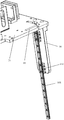
- FIG. 11 is a schematic perspective view of the grasping mechanism of FIG. 10.
- FIG. 12 is a schematic perspective view of an alignment member of the grasping mechanism of FIG. 11.
- FIG. 13 is a schematic partial perspective view of an alignment member of the grasping mechanism of FIG. 11.
- FIG. 14 is a schematic perspective view of a picking robot of the movable dense storage and picking device of FIG. 3.
- FIG. 15 is a schematic perspective view of the picking robot of FIG. 14 with the fixing base removed.
- FIG. 16 is a schematic perspective view of a fixing base of the picking robot of FIG. 14.
- FIG. 17 is a schematic top view of the combined storage system.
- FIG. 18 is a schematic side view of a combined storage system.
- FIG. 19 is a schematic perspective view of an embodiment of a combined storage system.
- FIG. 20 is a partial enlarged view of the combined storage system, showing a rail changing robot, a docking track, and a transition track.
- FIG. 21 is a schematic perspective view of another embodiment of the combined storage system.
- FIG. 22 is a schematic perspective view of another embodiment of the combined storage system.
- FIG. 23 is a flowchart of an embodiment of an assembly method of a combined storage system.
- FIG. 24 is a schematic diagram of an embodiment of a method for assembling a combined storage system in which a side plate of a box body can be expanded relative to a top plate.
- Fig. 25 is a schematic diagram of another embodiment of a method for assembling a combined storage system in which side plates on two opposite sides of a box body can be expanded relative to a top plate.
- the present application discloses a movable dense storage and sorting device.
- the movable dense storage and sorting device includes: a skid-mounted outer box, a plurality of bins, a storage platform, a track assembly, a box picking robot, and a picking robot.
- the skid-mounted outer box has a storage area and defines a storage end. Several bins are located in the storage area, and each bin is used to hold goods.
- the storage platform is located at the storage end of the skid-mounted outer box.
- the rail assembly is installed in the skid-mounted outer box and located above the bin.
- the box picking robot is slidably mounted on the track assembly and is located above the material box, and the box picking robot is used to move the box where the order product is located from the storage area to the storage platform.
- the picking robot is located in the skid-mounted outer box and is disposed adjacent to the storage platform.
- the picking robot is used to pick the order product from a bin located on the storage platform.
- the movable dense storage and picking device can be realized as an automatic retail car or a display car, etc. It uses a skid-mounted outer box, and most of the components are installed in the skid-mounted outer box, which can realize the movable function of the entire storage system.
- FIG. 1 is a perspective assembled view of an embodiment of a movable dense storage and sorting device.
- FIG. 2 is a schematic perspective view of a skid-mounted outer box of the movable dense storage and sorting device of FIG. 1.
- 3 is a schematic perspective view of the movable dense storage and sorting device of FIG. 1 after the skid-mounted outer box is removed, and the internal structure of the movable dense storage and sorting device can be seen.
- FIG. 4 is a schematic side view of FIG. 3, and the general arrangement of the internal components of the movable dense storage and sorting device can be seen.
- the movable dense storage and picking device includes a skid-mounted outer box 10, and a plurality of material boxes 12, a storage platform 14, a track assembly 16, a box picking robot 18, The picking robot 20 and the like.
- the skid-mounted outer box 10 is shown in a container design and includes a top wall 22, a bottom wall 24, and two side walls 26.
- a storage area 28 is formed in the skid-mounted outer box 10, and the front and back ends are open ends.
- One end (rear end) is defined as the storage end 30 and the other end (front end) is defined as the storage end 32.
- the storage terminal 30 is responsible for the storage operation of the goods.
- the storage box 28 is added to the storage container 28 from the storage terminal 30, for example, the storage box 28 is moved to the storage when the warehouse is first built.
- the outbound terminal 32 is responsible for the outbound operation of the goods.
- ordered goods the bin 12 containing the ordered goods is moved to the outbound warehouse. Terminal 32, and then pick out the order goods from the bin 12, for the user to pick up.
- the bin 12 is moved back to the storage area 28.
- a side window 34 may be provided on the side wall 26.
- a user interaction interface can also be installed on the skid-mounted outer box 10, for example, a display 36 is installed, and the display 36 communicates with the order system of the mobile dense storage and picking device to display a purchase interface for the user to directly purchase the product. Or display a QR code for users to scan and purchase products on their own terminal devices.
- a plurality of bins 12 are densely arranged in a three-dimensional direction to form a three-dimensional warehouse. There is no need to set up shelves.
- the bins 12 are directly stacked on each other to further increase the bin density.
- the storage area 28 has a plurality of bin positions 40 (FIG. 5) defined in two-dimensional coordinates on a horizontal plane, and a plurality of bins 12 are stacked vertically in each bin position 40. Therefore, each bin can be identified based on three-dimensional coordinates (horizontal, longitudinal, and height coordinates). More specifically, the number of bins 12 shown is divided into three columns in the horizontal direction, four rows in the length direction, and four layers in the height direction. Therefore, according to the number of columns where the bins 12 are located, the rows Number and level.
- the plurality of bins are arranged in N rows on a horizontal plane, and the track assembly includes N tracks corresponding to the N rows of bins.
- the movable dense storage and picking device It may also include a transition track perpendicular to the N tracks and a track changing robot running on the transition track.
- the track changing robot is provided with a docking track matching the end of the track in the track assembly, and the transition track is provided for The orbit changing robot moves in a forward direction to switch the box picking robot between N different orbits.
- the docking track is aligned with the end of the track in the corresponding track assembly, and can be used as an extension of the track. It is convenient for the box picking robot to move from the track in the track assembly to the docking track, and then the track changing robot moves along the transition track to the next one.
- the end of the switched track completes the switching of the box picking robot between N different tracks.
- FIGS. 6 and 7 are perspective views of a single bin 12.
- the bin 12 includes four side walls 42 and a bottom wall 44.
- the side walls 42 and the bottom wall 44 define a receiving space 46 for accommodating goods.
- the upper end of the bin 12 forms an opening 48 facing the bottom wall 44.
- a projection 50 is formed on the bottom surface of the bottom wall 44.
- the shape of the projection 50 is consistent with the shape of the opening 48.
- the material box 12 is shown in the shape of a rectangular parallelepiped, and has four corners when viewed from above, and the opening 48 and the boss 50 are rectangular. It should be understood that the shape shown is only an example, and other suitable shapes may also be used.
- Each of the two opposite side walls 42 of the bin 12 is provided with a gripping hole 52 at an upper portion thereof for gripping by a gripper of the gripping robot 18 (as described below with reference to the drawings).
- the storage platform 14 is disposed at the storage end 32 of the skid-mounted outer box 10 and is placed on the bottom wall 24 of the skid-mounted outer box 10.
- the unloading station 14 is used for receiving the bins 12 transferred from the storage area 28.
- the storage platform 14 has a supporting surface 53 for supporting the receiving bin 12.
- a plurality of storage locations 54 are provided on the storage platform 14, and each storage location 54 occupies a part of the support surface 53.
- the storage platform 14 is provided with three storage locations 54. Each storage location 54 corresponds to a row of bins 12.
- a box positioning mechanism is provided on the storage location 54.
- the bin positioning mechanism includes a lateral positioning piece 56 and a longitudinal positioning piece 58.
- the lateral positioning piece 56 and the longitudinal positioning piece 58 extend vertically upward from the support surface 53 of the storage platform 14, and are respectively used in the horizontal direction. And the longitudinal position of the bin 12 on the storage location 54.
- the storage end 30 of the skid-mounted outer box 10 is provided with a storage platform 60.
- the structure and function of the storage platform 60 are similar to those of the storage platform 14.
- the storage platform 60 can be completely consistent with the storage platform 14, so it will not be described again.
- a storage container is provided at the storage terminal position, and the storage container includes a storage container, a cargo transporting device located in the storage container, and the storage platform.
- the storage box includes a top plate, a bottom plate, and a detachable side plate connected between the top plate and the bottom plate, and the storage box of the storage container is horizontal with the same floor.
- a plurality of said skid-mounted outer boxes arranged in parallel directions are vertical, and internal spaces communicate.
- the loading and unloading box body of the loading and unloading container is vertically arranged with a plurality of skid-mounted outer boxes arranged in parallel in the horizontal direction, and the space in the loading and unloading container communicates with the discharge end of the skid-mounted outer box.
- a storage container is provided at the storage terminal 30, and the storage container includes a storage container, a cargo transporting device located in the container, and the storage platform. And a picking robot, the storage box includes a top plate, a bottom plate and a detachable side plate connected between the top plate and the bottom plate, and the storage box of the storage container is parallel to the same layer in the horizontal direction. A plurality of the skid-mounted outer boxes are arranged vertically, and the internal space is communicated.
- outbound and outbound containers at the inbound side and outbound and outbound containers at the outbound side here can be formed into the same standardized container.
- only the outbound and outbound containers at one end of the skid-mounted outer box Only one end of the outbound and inward storage container can realize the functions of outbound and inward storage of the goods, and it can also include the outbound and inward storage containers at the two ends of the skid-mounted outer box, respectively, to achieve the functions of outbound and inward storage of the goods.
- each outbound and outbound container may have only outbound function, only inbound function, or both outbound and inbound function.
- the picking robot and the storage / storage station may not be installed in a skid-mounted outer box, but may be installed in The outbound container.
- the rail assembly 16 is installed in the skid-mounted outer box 10 and located above the bin 12 in the storage area 28.
- the track assembly 16 includes three track units 62 correspondingly located above the three rows of bins 12, and a track picking robot 18 is slidably mounted on each track unit. Therefore, in the illustrated embodiment, there are three box picking robots 18, and each box picking robot 18 corresponds to a row of bins 12.
- three rows of bins 12, three storage positions 54, three storage positions, three track units 62, and three box picking robots 18 are provided, and correspond to each other.
- the number of rows of the bins 12, the number of storage positions 54, the number of storage positions, the number of track units 62, and the number of box picking robots 18 may not correspond. Choose according to the actual situation.
- FIG. 9 it is a schematic diagram of a partial structure of one of the track units 62.
- the track unit 62 includes two guide rails 64 spaced apart in the lateral direction, each of the guide rails 64 is provided with a guide groove 66, and the guide grooves 66 of the two guide rails 64 of the same track unit 62 are opposite to each other for cooperation with the box picking robot 18.
- Each guide rail includes a side wall 67 and a top edge 68 and a bottom edge 69 extending from the upper and lower edges of the side wall 67 toward the other guide rail 64.
- the side wall 67, the top edge 68, and the bottom edge 69 together form a C-shaped cross section.
- the box picking robot 18 includes a walking mechanism 70 and a grasping mechanism 72 suspended below the walking mechanism 70 and capable of lifting relative to the walking mechanism 70.
- the running mechanism 70 is slidably mounted on the track assembly 16 to move horizontally along the track assembly 16 to drive the grasping mechanism 72 to move horizontally.
- the traveling mechanism 70 is provided with a traveling roller 74 and a guide wheel 76 on both sides, and a driving device for driving the traveling roller 74 to roll is provided inside.
- Four traveling rollers 74 are provided on both sides of the traveling mechanism 70, two on each side.
- Two walking rollers 74 on one side travel on the bottom edge 69 of one of the guide rails 64 of the track unit 62, and two walking rollers 74 on the other side travel on the bottom edge 69 of the other guide 64 of the track unit 62.
- the guide wheels 76 on both sides walk on the side walls 67 of the two guide rails.
- the four walking rollers 74 are synchronized to obtain power to move in the track, and the load of the box picking robot 18 is evenly distributed to the four walking rollers 74.
- the guide wheel 76 can solve this problem. Under the action of the guide wheel 76, the walking roller 74 and the side wall 67 of the guide rail remain stable. It can reduce and control the jitter of the vehicle body, increase the stability of the vehicle body, and avoid the undesired shaking of the material box 12 under the box picking robot 18.
- the grasping mechanism 72 includes a grasper platform 78, a grasper 80, and an alignment mechanism.
- a lifting mechanism is provided between the gripping platform 78 and the walking mechanism 70 for lifting the gripping platform 78.
- the lifting mechanism includes a lifting bar 82 and a lifting driving device.
- the upper end of the lifting bar 82 is connected to the lifting driving device, and the lower end of the lifting bar 82 is fixed on the gripper platform 78.
- the lifting driving device is disposed in the traveling mechanism 70 and includes a driving motor and a winder connected to the driving motor.
- the upper end of the lifting bar 82 is wound on the winder, and the winder is on the driving motor. The winding operation is performed under the driving of the driving device, thereby the lifting and lowering operations of the lifting bar 82 are realized.
- the lifting bar 82 may be a flexible steel bar or a steel rope.
- the gripper 80 is disposed on the side of the gripper platform 78 for gripping the side wall 42 of the bin 12.
- two grippers 80 are provided, which are respectively located on opposite sides of the gripper platform 78 and are respectively used to grip the two gripping holes 52 of the bin 12.
- the gripper platform 78 is also provided with a gripper driving device for driving the gripper 80 to rotate about the rotation axis 86 between the gripping position and the releasing position. Among them, in the grasping position, the grasping hand 80 is rotated to extend into the grasping hole 52, and in the releasing position, the grasping hand 80 is rotated outward to exit the grasping hole 52.
- the grip drive may be implemented in any suitable form.
- the gripper driving device includes a motor 84 and a link mechanism driven by the motor.
- One of the links 85 of the link mechanism is connected to the upper end of the gripper 80.
- the link 85 drives the gripper to rotate about the rotation shaft 86 between the gripping position and the releasing position.
- the alignment mechanism includes a plurality of alignment members 90 disposed at corner positions of the gripper platform 78.
- the number of the alignment members 90 is four, which respectively correspond to the four corners of the bin 12.
- Each alignment member 90 includes a vertically extending portion 92 that extends vertically downward, and an alignment inclined surface 94 that extends downward and outward from a bottom end of the vertical extension portion 92.
- the boss 50 of the captured bin 12 will It is misaligned with the opening 48 of the lower bin 12 and cannot achieve normal stacking.
- the alignment inclined surface 94 will be in sliding contact with the upper edge of the side wall of the lower bin 12, thereby finely adjusting the position of the upper bin 12 on the horizontal plane, so that the caught bin 12 is aligned with the lower bin 12 .
- an alignment mechanism is provided on the grasping mechanism 72 to achieve accurate alignment in the vertical direction. There is no need to set a high-cost position detection mechanism on the box picking robot 18, which effectively reduces costs.
- the vertical extension 92 of each alignment member 90 includes a first alignment plate 92A and a second alignment plate 92B.
- the first alignment plate 92A and the second alignment plate 92B are perpendicular to each other, so that the cross section of the alignment member 90 parallel to the horizontal plane is L-shaped.
- the first alignment plate 92A and the second alignment plate 92B are configured to abut against the outer surfaces of two adjacent sidewalls of the grabbed bin 12, that is, the outer surfaces of two adjacent sidewalls forming one corner thereof.
- the alignment inclined surface 94 includes a first alignment inclined surface 94A extending downward and outward from the bottom end of the first alignment plate 92A and a first alignment inclined surface 94A extending downward and outward from the bottom end of the second alignment plate 92B.
- the first alignment inclined surface 94A and the second alignment inclined surface 94B of each alignment member 90 intersect with each other or there is a small gap (which can be regarded as an intersection).
- the first alignment plate 92A and the second alignment plate 92B have a first intersection line 92C
- the first alignment slope 94A and the second alignment slope 94B have a second intersection line 94C.
- the first intersecting line 92C and the second intersecting line 94C are located in the same vertical plane. In this way, the relative positions of the upper and lower bins 12 can be smoothly corrected by using the first alignment slope 94A and the second alignment slope 94B.
- the alignment mechanism is provided with a mounting member 96 fixed to the gripper platform 78 corresponding to each alignment member 90.
- the positioning member 90 is attached to the gripper platform 78 using a mounting member 96.
- the bin When the grasping mechanism 72 grabs a bin and moves to a certain bin position, the bin may be located on another bin (that is, the bin is above the first floor in the height direction), or it may be It is placed directly on a platform or the ground (that is, the bin is located on the first floor in the height direction). If it is the latter, the positioning member 90 will contact the platform or the ground first, so that when the positioning member 90 is already in contact with the platform or the ground, the grabbed bin cannot contact the platform or the ground. If the gripper 80 is released at this time, the bin 12 will fall on the platform or the ground and the goods in the bin 12 may be damaged.
- a slide rail assembly is provided between the mounting member 96 and the positioning member 90, so that the positioning member 90 can slide upward under the action of the platform or the ground reaction force, so that the bin 12 can slowly land.
- the alignment inclined surface 94 of the positioning member 90 It will be in sliding contact with the upper edge of the side wall of the lower material box 12 at this time, and the upper edge of the side wall of the lower material box 12 will apply an oblique upward thrust to the alignment inclined surface 94.
- the damping force of the slide rail assembly is designed to be greater than the vertical force component of the pushing force applied by the lower bin to the registration inclined surface 94.
- the positioning member 90 is removed in the drawing to more clearly show the mounting member 96 and the slide rail assembly.
- the mounting member 96 extends vertically downward from the gripper platform 78.
- the slide rail assembly includes a first rail 98A fixed on the mounting member and a second rail 98B fixed on the positioning member 90.
- the first rail 98A and The second guide rail 98B is slidably fitted.
- the first guide rail 98A includes two projections, each projection forming a guide groove on a surface facing the second guide rail 98B, and the second guide rail 98B is slidably received in the guide grooves of the two projections.
- the gripping platform 78 is provided with a mounting hole 99 corresponding to each positioning member 90, and the positioning member 90 is slidably mounted in the mounting hole 99.
- the mounting hole 99 is L-shaped.
- the picking robot 20 includes a moving base 100 and a robot hand 102.
- the moving base 100 is movable relative to the bin 12.
- the manipulator 102 is supported by the mobile base 100 so as to be movable with the mobile base 100.
- the manipulator 102 is used for picking order goods in a bin to at least one shipping port 104 (FIGS. 1 and 3).
- the bin 12 containing the ordered product will be carried by the picking robot 18 to the storage location 54 of the outbound platform 14, and the robot 102 picks the ordered product from the bin 12 to the out Cargo port 104 for users to pick up.
- the storage platform 14 has a plurality of storage locations 54, and each storage location 54 is used to receive a bin 12.
- the moving base 100 is movable along the arrangement direction of these out-of-stock locations 54. Therefore, if the bin 12 where the order product is located is far away from the robot 102, the moving base 100 can slide toward the bin 12, so that Under the premise that the robot 102 needs to be lengthened, the picking operation is improved.
- the picking robot 18 is located in the skid-mounted outer box 10, and its moving base 100 is movably supported on a fixed base 106, wherein the fixed base 106 is fixedly placed in the skid-mounted outer box 10 near the storage platform 14.
- the fixed base 106 is provided with a supporting table 108, one of the supporting table 108 and the moving seat 100 is provided with a guide rail, and the other of the supporting table 108 and the moving seat 100 is provided with a guide groove, and the guide rail is slidably received in the guide groove. In this way, the mobile base 100 is moved on the fixed base 106.
- At least one bump 110 is provided on each side edge of the bottom surface of the moving base 100, and each bump 110 is provided with a groove 112, and the groove 112 forms the guide groove.
- the bottom surface of the moving base 100 is provided with four bumps 110, wherein the grooves 112 of the two bumps 110 form a guide groove, and the grooves 112 of the other two bumps 110 form another guide groove.
- Two guide rails are correspondingly fixed on the supporting platform 108 of the fixing base 106.
- a stopper 116 is also provided at each of the four corner positions of the support table 108 to limit the movement of the mobile seat 100.
- a rack 118 is provided on the support table 106, and the rack 118 is parallel to the moving direction of the picking robot 20.
- the moving base 100 is provided with a motor 120, and a gear 122 is fixed on an output shaft of the motor 120 so that the gear 122 can rotate with the output shaft.
- the gear 122 meshes with the rack 118.
- the gear 122 When the gear 122 is driven to rotate by the motor 120, the gear 122 will travel along the rack 118, thereby driving the moving base 100 to move.
- the scheme of matching gears and racks is only an example. In other embodiments, the mobile seat 100 may adopt other suitable driving schemes.
- the number of the shipping ports 104 is four. In other embodiments, the number of the shipping ports 104 may be other numbers, which are not limited in this application.
- the picking robot 18 is located between the storage platform 14 and the shipping port 104, and the shipping port 104 is located outside the skid-mounted outer box 10. In other embodiments, the shipping port 104 may also be located inside the skid-mounted outer box 10.
- the present application also discloses a commodity picking component of such an automatic storage system, which includes:
- At least one bin 12 the bin 12 is used to hold goods
- At least one shipping port 104 (eg, the four shipping ports shown) for receiving a commodity from the at least one bin 12;
- a picking robot 18 includes:
- a moving base 100 that is movable relative to the bin 12;
- a manipulator 102 supported by the moving base so as to be movable with the moving base 100.
- the manipulator 102 is used for picking order goods in the bin 12 to the shipping port 104.
- the above-mentioned embodiment of the present invention provides a movable dense storage and sorting device.
- the movable dense storage and sorting device includes: a skid-mounted outer box, a plurality of bins, a storage platform, a track assembly, and a picking box. Robots and picking robots.
- the skid-mounted outer box has a storage area and defines a storage end. Several bins are located in the storage area, and each bin is used to hold goods.
- the storage platform is located at the storage end of the skid-mounted outer box.
- the rail assembly is installed in the skid-mounted outer box and located above the bin.
- the box picking robot is slidably mounted on the track assembly and is located above the material box, and the box picking robot is used to move the box where the order product is located from the storage area to the storage platform.
- the picking robot is located in the skid-mounted outer box and is disposed adjacent to the storage platform.
- the picking robot is used to pick the order product from a bin located on the storage platform.
- the movable dense storage and picking device can be realized as an automatic retail car or a display car, etc. It uses a skid-mounted outer box, and most of the components are installed in the skid-mounted outer box, which can realize the movable function of the entire storage system.
- the positioning mechanism of the gripping mechanism of the box picking robot can realize accurate positioning in the vertical direction without the need for a high-cost position detection mechanism on the box picking robot, which effectively reduces costs.
- the slidable picking robot is designed to improve picking operations without the need for an extended robot.
- the storage and picking of bins in the above-mentioned mobile dense storage and picking device can also be formed as standardized and independent container components.
- skid-mounted outer boxes, bins, track components, and picking boxes Robots are collectively formed into standard independent storage containers; it is possible to collectively form loading and unloading stations and picking robots as standard and independent loading and unloading containers; it is possible to collectively form rail changing components such as rail changing robots and rails into standard, Independent rail-changing containers make it easy to select the corresponding number of container components for splicing according to the capacity requirements of the required storage system.
- the components in the outbound and inbound containers and the components in the track change container can be integrated in the same container. It is also not necessary to provide a track changing component, or the track changing component is integrated in the storage container.
- FIGS. 17 to 20 is a combined storage system according to an embodiment of the present invention, which includes a plurality of storage containers 200, at least one rail changing container 202, and at least one storage container 204.
- a plurality of storage containers 200 are combined along the length direction and width direction of the storage container 200.
- One or more rail changing containers 202 are disposed at both ends of the length direction of the plurality of storage containers 200, and one or A plurality of storage containers 204 are provided outside the rail changing container 202.
- the storage container 200, the rail changing container 202, and the storage container 204 are standardized containers, and the number is increased or decreased according to a demand and in a given splicing manner. For example, according to the number of storage containers 200 combined in the width direction, the number of combined rail change containers 202 changes accordingly, and the number of combined storage containers 204 also changes accordingly.
- the combined storage system can be provided with one or more layers in the height direction of the container, and the layout of each floor can refer to FIG. 17.
- FIG. 19 and 20 illustrate the combined structure and principle of the present application in detail with a simplified embodiment.
- the example in FIG. 19 is a two-story structure.
- the rail change container is perpendicular to the storage container 200. Place.
- the rail change container and the storage container are combined into one, that is, the components in the rail change container and the storage container are integrated in the same container. Therefore, this container can be referred to as a derailment container with a derailment function (with a derailment device), and can also be referred to as a derailment container with a derailment function (with a derailment component).
- this container is referred to as a rail changing container 202 in this embodiment.
- a plurality of the storage containers 200 are combined to form a combined storage area.
- the combined storage area is provided with a track assembly 206, a box picking robot 208 located on the track assembly 206, and a plurality of bins 210 located below the box picking robot 208.
- the bin 210 is used for storing goods.
- the box picking machine 208 can run back and forth on the track assembly 206 to access the bin 210.
- the structure and principle of the above-mentioned track assembly 206, the box-taking robot 208, and the material box 210 may be consistent with related elements in the embodiment illustrated in FIGS. 1-16, so detailed details thereof will not be repeated.
- the above combined storage area should be understood as the sum of the storage areas formed by each container.
- the combined storage area includes five sub storage areas 212, each of which is formed by one storage container 200.
- Each of the sub storage areas 212 is provided with the above-mentioned track assembly 206, a box picking robot 208, and a bin 210.
- the storage container 200 includes a container box including a bottom plate 214, a top plate 216, two side plates 218 connected to the long sides of the top plate 216 and the bottom plate 214, and two end plates connected to the short sides of the top plate 216 and the bottom plate 214. 220.
- the track assembly 206, the box picking robot 208, and the bin 210 are all disposed in a container box of the storage container 200.
- the track of the track assembly 206 extends along the length of the storage container 200.
- the rail changing container 202 also has a bottom plate 214, a top plate 216, two side plates 218 connected to the long sides of the top plate 216 and the bottom plate 214, and two end plates 220 connected to the short sides of the top plate 216 and the bottom plate 214. .
- the internal space of the rail-changing container 202 communicates with the internal space of the storage containers 200 (ie, a sub-storage area 212).
- a rail changing device is provided in the rail changing container 202, and the rail changing device is configured to switch the box picking robot 208 in at least one of the storage containers 200 from a current running track where the box picking robot is located to a target running track.
- the track changing device includes a transition track 222 and a track changing robot 224.
- the transition rail 222 is already installed in the rail change container 202, for example, it is installed to the top plate 216 or the side plate 218 of the container box of the rail change container 202 by a connecting member.
- the rail changer robot 224 is located on the transition rail 222 and is capable of moving back and forth on the transition rail 222.
- the orbit changing robot 224 is configured to receive the box picking robot and transport the box picking robot along the transition track 222 to the target running track.
- a docking track 226 matching the end of the track assembly 206 is provided on the track changing robot 224.
- the transition track 222 extends along the length of the track change container 202 and is perpendicular to the running track 206 in each row of the storage container.
- the rail changing robot 224 includes a vehicle body and a walking mechanism installed on the vehicle body and adapted to the transition track. The walking mechanism is connected to and driven by the driving device, and drives the rail changing robot to move back and forth along the transition track.
- the docking track 226 is provided on the body of the track changing robot 224. When the track changing robot 224 moves along the transition track 222 to directly face the running track 206 in a row of storage containers, the docking track 226 happens to be in the storage container.
- the running track 206 is at the same height, and the docking track 226 on the body of the track changing robot 224 is aligned with and connected to the end of the running track in the storage container in this row. Slide directly along the running track 206 onto the docking track 226 on the track changing robot 224. Then the orbit changing robot 224 is driven along the transition track to change the orbit of the orbit changing robot 224 and a storage container in a different row, and the docking track 226 on the body of the orbit changing robot 224 is in the same storage container. The ends of the running track are aligned and connected to each other.
- the container picking robot 208 in the storage container can slide from the docking track 226 on the track changing robot to the running track in the different row of storage containers, which is completed by the box picking robot.
- the switching between the rail assemblies 206 of the storage containers of different columns is realized by the rail changing container 202.
- the structure and principle of the rail change mechanism are described in detail in the Chinese invention patent application entitled “Three-Dimensional Storage System” filed by the applicant on July 24, 2018. The entire content of the Chinese invention patent application is incorporated by reference. Incorporated herein.
- the functions of the outbound storage container are integrated in the rail change container 202.
- the rail-change container 202 is provided with a storage-out device for performing a storage-out operation of the cargo.
- the loading and unloading device includes a loading platform 228, which is disposed on the bottom plate 214 of the loading / unloading container / rail changing container 202 and below the transition rail 222 for temporary storage of the bins .
- the loading / unloading device is installed in the rail change container 202 before the rail change container 202 is installed at one end of a plurality of storage containers 200.
- the bin 210 in the storage container 200 is taken out by the bin picking robot 202, and the rail changing robot 224 carries the bin picking robot 202 to move the bin 210 to a designated position on the shelf.
- an operator or a robot may be deployed in the outbound / outbound container / rail changing container 202 to perform a cargo picking operation.
- a cargo conveying device may also be provided in the outbound / outbound container / rail change container 202, which is responsible for moving the bins out of the warehouse.
- FIG. 19 illustrates a fixed storage-out device, that is, the material box is immovable on the shelf.
- FIG. 21 illustrates another storage and retrieval device, which is a pipelined storage and retrieval device.
- FIG. 21 illustrates another storage and retrieval device, which is a pipelined storage and retrieval device.
- two storage and retrieval methods are exemplified in this article, it should be understood that there can be more embodiments of the storage and retrieval device, as long as the storage and retrieval function of goods can be realized.
- they are all called "outbound and outbound devices", according to different situations, they can only implement outbound functions, only inbound functions, or both outbound and outbound functions.
- Figure 22 is similar to Figure 21, except that two storage containers are shown on each floor.
- the derailment container 202 has a storage and retrieval device at the same time, that is, a container with a derailment function and a decommissioning function is combined with the storage container 200.
- a container that does not have a track changing function and has only a storage and retrieval function may be combined with the storage container 200, that is, a storage and retrieval container 202 that does not have a track changing function and the storage container 200 are combined.
- an embodiment of the present invention provides a combined storage system, including:
- a plurality of storage containers, and a plurality of the storage containers are combined to form a combined storage area, and the combined storage area is provided with a track assembly, a box picking robot located on the track assembly, and a box picking robot located below the box picking robot
- a plurality of bins, the bins are used to store goods, the box picking robot can run back and forth on the rail assembly to access the bins, the rail assemblies are fixed on the board of the storage container Physically;
- At least one storage container the storage container is provided with a storage device for performing the storage operation of the goods.
- the internal space of the storage container is in communication with the combined storage area, so that the picking robot can A bin is transported between the combined storage area and the storage device.
- the storage and retrieval device is the same as the storage and retrieval device of the foregoing embodiment, and details are not described herein again.
- the box picking robot directly transports the goods to the storage / receiving device, for example, to the storage platform without the assistance of the rail changing robot.
- the storage container When there are a plurality of storage containers combined along the width direction of the storage container, the storage container is perpendicular to the storage containers combined along the width direction, and the internal space of the storage container and the storage container An internal space formed by the plurality of storage containers arranged in the width direction communicates.
- the at least two storage containers are combined along the length direction of the storage containers, and when the at least two storage containers are combined, adjacent end plates are removed to realize the interior. Connect with each other. .
- FIG. 23 is an assembly method of a combined storage system. The method includes:
- Each storage container defines a length direction and a width direction.
- the combined storage containers include one or more storage containers, and each layer includes parallels in the width direction.
- a plurality of storage containers arranged and combined, and a track for a box picking robot operation is set in the combined storage area, wherein the tracks are already installed in a plurality of the containers before a plurality of the storage containers are combined;
- the transition track inside is perpendicular to the track inside the storage container on the same floor, and the transition track is configured for a reciprocating operation of the rail changing robot, wherein the transition track in the rail changing container is installing the rail changing container Up to the ends of a plurality of the storage containers have been previously fixed into the rail change container.
- each storage container and rail-changing container includes a container box, the container box including a bottom plate, a top plate, two side plates connecting the bottom plate and the long side of the top plate, and connecting the bottom plate And the short sides of the top plate.
- the assembly method further includes placing the depot storage container 204 in parallel with the outside of the derailment container 202, and the number of the depot storage container 204 is the same as the number of the derailment container.
- the container body of the outbound container also has a bottom plate, a top plate, two side plates connecting the bottom plate and the long side of the top plate, and two end plates connecting the bottom plate and the short side of the top plate. Adjacent end plates are removed when the outbound and inbound containers 204 are combined along their length direction, so that the internal space of the adjacent outbound and inward containers 204 is communicated.
- the rail change container and the inbound and outbound container are assembled, the rail change container 202 and the Adjacent side panels of the outbound storage container 204 are removed to achieve internal space communication between the two.
- the adjacent end plates are removed to realize the internal space communication of the adjacent storage containers 200.
- the containers are arranged neatly so that the corner pieces of the container are aligned, the corner pieces of the container are fixed in the height direction by the connecting pieces, and the container gap is sealed by the sealing pieces.
- each container was densely assembled. Except that part of each container of the container was removed, the respective volume of the storage container 200 remained unchanged.
- Each of the sub-storage areas was formed by one of the storage containers 200.
- the total volume of the combined storage area is substantially equal to the sum of the volumes of all the storage containers 200. However, in some other embodiments, the total volume of the combined storage area may be larger than the sum of the volumes of all storage containers.
- Figures 24 and 25 show another method of container assembly or splicing. Wherein, combining a plurality of the storage containers includes:
- a horizontally arranged plate is bridged between two adjacent storage containers.
- a distance between adjacent storage containers is spaced, and then a horizontal board is used to bridge the distance.
- An additional sub-storage area is formed below for more cargo.
- the horizontally arranged plate can have multiple implementations, and FIG. 24 and FIG. 25 show two methods, which are described below.
- a storage container 200 is provided first.
- the container body of the storage container 200 has a bottom plate 214, a top plate 216, and two side plates 218 connected to the long sides of the top plate 216 and the bottom plate 214.
- One side 230 of one of the side plates 218 is rotatably connected to the top of the storage container 200.
- step 24 (b) the other side of the side plate 218 of each storage container 200 is turned outwards and upwards by 90 degrees to be horizontal.
- step 24 (c) the other free side of the side plate 218 is supported and connected by an adjacent storage container, and is maintained in a horizontal state. Connected in this way, several storage containers are spliced along the width direction of the storage container. In this way, an additional sub-storage area is formed under each side plate 218 that is turned horizontally, which can store additional bins.
- step 24 (d) another layer structure is spliced in the same way to realize a multi-layer storage system.
- the plate body is a reversible side plate of the storage container. Taken together, each storage container 200 has two sub-storage areas formed by unfolding a single side panel, that is, using the same number of storage containers to double the storage space of the bin. It should be noted that the above steps do not limit the execution order.
- steps 24 (b) and 24 (c) the side plate 218 that has been turned to the horizontal state can be supported and connected to an adjacent storage container. , And then flip the side plates 218 of the adjacent storage container. Before the storage container is transported, the side of the side plate 218 has been installed with a track for the box picking robot 208 to run. After the flip, the track is located on the lower surface of the side plate 218 placed horizontally. Therefore, in this embodiment, a rail is pre-installed on the top plate of the storage container and one of the side plates to be turned over.
- a storage container 200 is first provided.
- the container body of the storage container 200 has a bottom plate 214, a top plate 216, and two side plates 218 connected to the long sides of the top plate 216 and the bottom plate 214.
- One side 230 of each side plate 218 is rotatably connected to the top of the storage container 200.
- the two side plates 218 of an adjacent storage container 200 are also turned to the horizontal state in the same manner.
- a support body 232 is provided between two adjacent storage containers 200. In this embodiment, there are several support posts 232.
- the other sides of the two side plates 218 are docked and supported by the supporting body 232, so that the two side plates 218 are maintained in the horizontal state.
- an additional sub-storage area is formed under each side plate 218 that is turned horizontally, which is equivalent to forming two additional sub-storage areas between two adjacent storage containers 200, which can store additional Bin.
- the support post 232 is located at an intermediate position between two adjacent storage container boxes 200.
- the plate body is two reversible side plates of the storage container.
- each storage container 200 forms three sub-storage areas by expanding the double-sided side plates, that is, With the same number of storage containers, the storage space of the three-folded bin is realized.
- the above steps do not limit the execution order.
- the side plate 218 of the storage container that has been turned to the horizontal state may be supported by the support body 232, and then Turn over the side panels 218 of the adjacent storage containers.
- the inside of the side plate 218 is already installed with a track for the box picking robot 208 to run. After the flip, the track is located on the lower surface of the side plate 218 placed horizontally. Therefore, in this embodiment, the top and both sides of the storage container are pre-installed with rails.
- the standardized storage container and the change rail container are stacked and combined according to a set manner, and the standardized storage container box and the change rail container are
- the boxes are respectively formed with detachable side plates, which facilitates the process of stacking storage containers and rail-changing containers.
- the side plates adjacent to each other can be disassembled and connected to form an integrated combined storage system for internal space communication.
- the invention has a modular idea, can be expanded, and the capacity of the warehouse can be adjusted by the number of containers and arrangement.
- the storage containers, rail-changing containers, and storage containers are standardized containers, which are easy to manufacture, low in cost, convenient to fix, save the time for infrastructure construction, and realize rapid deployment and mobile layout of automated warehouses.
Abstract
一种组合式仓储系统及组装方法,多个存储集装箱(200)组合在一起形成一组合存储区,组合存储区内设置有轨道组件(206)、取箱机器人(208)以及若干料箱(210);至少一换轨集装箱(202)的内部空间与多个存储集装箱(200)的至少其中之一存储集装箱(200)的内部空间连通,换轨集装箱(202)内设有换轨装置,换轨装置构造成用以将至少其中之一存储集装箱(200)内的取箱机器人(208)从取箱机器人(208)所在的当前运行轨道切换至一目标运行轨道上,至少一出入库集装箱(204)的内部空间与换轨集装箱(202)的内部空间连通,出入库集装箱(204)内设有出入库装置,用于执行货物的出入库操作。
Description
本发明涉及一种物流仓储技术,具体为一种可移动式密集存拣装置、组合式仓储系统及其组装方法、料箱抓取机构。
现有物流仓储或仓库中需要大量用到货架。现有的货架很多是自带滚轮的移动货架,移动货架设置在轨道上,货架通过驱动装置,在轨道上来回跑动输送货物。为了提高效率,通常货架有多层,每层上面都要放置货物。由于货架上载有货物,货架在移动需要耗费较多电能,而且针对某一个货架的分拣、上货、下货等动作,整个货架系统均需要整体启动和运动,能源耗费较高,特别是无效的电能消耗高,电能利用率低。每个移动货架往往重达数百公斤,移动货架在整体的移动过程中,彼此碰撞等损耗较大,对轨道、以及制动系统具有较高要求。在现有的货架循环运动体系中,常见的货架转向设计为轨道回路设计,即货架轨道具有较大的转弯半径,货架在该转弯轨道进行转向循环。在目前的货架换轨设计中,也有采用横移装置的,即在轨道两端设计横移轨道,在横移轨道上设有货架移载装置,货架通过移载装置转移到另外一个轨道上。由于货架通过为多层结构,其具有很大的重量,其转入移载装置后,移载装置需要较大的拖动功率。该结构对移载装置的承重强度、抗击打强度和功率均有较高的要求。此类专利如中国专利申请号为201610955227.0,名称为:自动密集仓库装置,公开日为2017年2月8日的专利文献,其公开了一种在轨道上置放货架的仓储系统。此类货架仓储系统对于货物堆高不高的情况适用还可以,但是对于较高层的情况,堆货太高,运动过程中会不安全,且无效搬运能源损耗太大。
而且,上述讨论的货架系统也不能应用于可移动式零售系统,例如在展会临时出现的小型零售车。现有的小型零售车一般都是人工操作,鲜有见到使用自动仓储系统。
另外,目前的自动仓库现场安装复杂,技术要求高。而且一旦安装好,扩容或减容不易,无法使用目前快速变化的市场需求。
发明内容
本发明所要解决的技术问题是提供一种可移动式密集存拣装置、组合式仓储系统及其组装方法,其采用全新的自动仓储系统,使得移动式零售系统也可以采用自动仓储系统。
本发明要解决的另一技术问题是提供一种容易现场安装,可灵活构建仓库容量符合所需的组合式仓储系统,成本低、固定方便、节省了基础设施建造的时间,实现自动化仓库的快速部署和移动布置。
一方面,本文提出的一种可移动式密集存拣装置包括:撬装外箱,所述撬装外箱内具有一仓储区并定义一出库端;若干个料箱,所述若干个料箱位于所述仓储区,每个料箱用于容纳商品;出库台,所述出库台位于所述撬装外箱的出库端;轨道组件,所述轨道组件安装在所述撬装外箱内并位于所述料箱上方;取箱机器人,所述取箱机器人可滑动地安装在所述轨道组件上并位于所述料箱上方,所述取箱机器人用于将订单商品所在的料箱从所述仓储区搬运至所述出库台。
另一方面,本文提出一种组合式仓储系统,包括:多个存储集装箱,多个所述存储集装箱组合在一起形成一组合存储区,所述组合存储区内设置有轨道组件、位于所述轨道组件上的取箱机器人以及位于所述取箱机器人下方的若干料箱,所述料箱用于存放货物,所述取箱机器人能够在所述轨道组件上往返运行以对所述料箱进行存取操作;至少一换轨集装箱,所述换轨集装箱的内部空间与多个所述存储集装箱的至少其中之一存储集装箱的内部空间连通,所述换轨集装箱内设有换轨装置,所述换轨装置构造成用以将所述至少其中之一存储集装箱内的取箱机器人从所述取箱机器人所在的当前运行轨道切换至一目标运行轨道上;以及至少一出入库集装箱,所述出入库集装箱的内部空间与所述换轨集装箱的内部空间连通,所述出入库集装箱内设有出入库装置,用于执行货物的出入库操作。
另一方面,本文提出一种组合式仓储系统的组装方法,包括:组合多个存储集装箱形成一组合存储区,每个存储集装箱定义一长度方向和一宽度方向,组合后的多个存储集装箱包括一层或多层存储集装箱,每一层包括沿所述宽度方向平行排列并组合的多个存储集装箱,所述组合存储区内设置有供取箱机器人运行的轨道,其中所述轨道在组合多个所述存储集装箱之前就已经安装至多个所述集装箱内;将换轨集装箱安装至每一层多个存储集装箱在所述长度方向上的至少一端,使所述换轨集装箱内的空间与同层所述存储集装箱内的空间连通,并使所述换轨集装箱内的过渡轨道与同层的所述存储集装箱内的轨道垂直,所述过渡轨道构造成用以供换轨机器人往返运行,其中所述换轨集装箱内的过渡轨道在将所述换轨集装箱安装至多个所述存储集装箱的所述端之前就已经固定至所述换轨集装箱内。
另一方面,本文提出一种料箱抓取机构,用于抓取一料箱,包括可升降的抓手平台以及安装在所述抓手平台上的抓手,所述抓手用于抓住所述料箱的边框,其特征在于,还包括对位机构,所述对位机构包括设置在所述抓手平台的角落位置的多个对位件,每个对位件包括 垂直向下延伸的垂直延伸部以及从所述垂直延伸部的底端向下并向外延伸的对位斜面,当所述料箱抓取机构已抓取所述料箱时,所有对位件的垂直延伸部都与所述料箱的边框外表面贴靠,且所述对位斜面全部位于所述料箱的底部下方,所述对位斜面构造成用以当已抓取的所述料箱与一个下方的第二料箱在竖直方向有偏差时,所述对位斜面与所述第二料箱的边框上缘滑动接触。
又一方面,本文提出一种组合式仓储系统,包括:多个存储集装箱,多个所述存储集装箱组合在一起形成一组合存储区,所述组合存储区内设置有轨道组件、位于所述轨道组件上的取箱机器人以及位于所述取箱机器人下方的若干料箱,所述料箱用于存放货物,所述取箱机器人能够在所述轨道组件上往返运行以对所述料箱进行存取操作,所述轨道组件固定在所述存储集装箱的板体上;以及至少一出入库集装箱,所述出入库集装箱内设有出入库装置,用于执行货物的出入库操作,所述出入库集装箱的内部空间与所述组合存储区连通,使得所述取箱机器人能够在所述组合存储区和所述出入库装置之间运送料箱。
本申请公开的各种方案的有益效果如下:
本发明提供了一种可移动式密集存拣装置,该可移动式密集存拣装置包括:撬装外箱、若干料箱、出库台、轨道组件、取箱机器人及拣选机器人。该撬装外箱内具有一仓储区并定义一出库端。若干个料箱位于所述仓储区,每个料箱用于容纳商品。出库台位于所述撬装外箱的出库端。所述轨道组件安装在所述撬装外箱内并位于所述料箱上方。所述取箱机器人可滑动地安装在所述轨道组件上并位于所述料箱上方,所述取箱机器人用于将订单商品所在的料箱从所述仓储区搬运至所述出库台。所述拣选机器人位于所述撬装外箱内并邻近所述出库台设置,所述拣选机器人用于从位于所述出库台上的料箱中拣选所述订单商品。所述可移动式密集存拣装置可以实现为自动零售车或展示车等,其采用撬装外箱,绝大多数元件都安装在撬装外箱内,可以实现整个仓储系统的可移动功能。除此之外,取箱机器人的抓取机构的对位机构的设置,可以实现竖直方向上的精确对位,无需在取箱机器人上设置高成本的位置检测机构,有效降低成本。而且,可滑动的拣选机器人的设计可以在不需要加长机械手的前提下,改善拣选操作。
另一方面,本发明提供一种组合式仓储系统,包括存储集装箱、换轨集装箱和出入库集装箱中的一种或多种。可灵活构建仓库容量符合所需的组合式仓储系统,成本低、固定方便、节省了基础设施建造的时间,实现自动化仓库的快速部署和移动布置。
再一方面,本发明提供一种上述组合式仓储系统的组装方法,通过形成标准化、模块化的集装箱,将标准化的集装箱根据设定的方式堆叠并组合,且标准化的集装箱的集装箱体分 别形成为具有可拆卸或可翻转的侧板,便于将集装箱堆叠组合的过程中,可以将彼此相邻的侧板拆卸或翻转后连接而形成内部空间连通的整体组合式仓储系统,实现自动化仓库的快速部署和移动布置。
图1是可移动式密集存拣装置的一个实施例的立体示意图。
图2是图1的可移动式密集存拣装置的撬装外箱的立体示意图。
图3是图1的可移动式密集存拣装置去掉撬装外箱的立体示意图。
图4是图3的可移动式密集存拣装置的侧面示意图。
图5是一种料箱排布的简化示意图。
图6是料箱的立体示意图。
图7是料箱另一角度的立体示意图。
图8是出库台一实施例的立体示意图。
图9是轨道组件的一个轨道单元的局部示意图。
图10是图3的可移动式密集存拣装置的取箱机器人的立体示意图。
图11是图10的抓取机构的立体示意图。
图12是图11的抓取机构的对位件的立体示意图。
图13是图11的抓取机构的对位件的局部立体示意图。
图14是图3的可移动式密集存拣装置的拣选机器人的立体示意图。
图15是图14的拣选机器人去掉固定座的立体示意图。
图16是图14的拣选机器人的固定座的立体示意图。
图17是组合式仓储系统的俯视示意图。
图18是是组合式仓储系统的侧视示意图。
图19是组合式仓储系统的一个实施例的立体示意图。
图20是组合式仓储系统的部分放大图,其中示出了换轨机器人、对接轨道及过渡轨道。
图21是组合式仓储系统的另一个实施例的立体示意图。
图22是组合式仓储系统的又一个实施例的立体示意图。
图23是组合式仓储系统的组装方法的一个实施例的流程图。
图24是组合式仓储系统的组装方法中,箱体的一侧板可相对顶板展开的一个实施例的示意图。
图25是组合式仓储系统的组装方法中,箱体的两相对侧的侧板可相对顶板展开的另一个 实施例的示意图。
在详细描述实施例之前,应该理解的是,本发明不限于本申请中下文或附图中所描述的详细结构或元件排布。本发明可为其它方式实现的实施例。而且,应当理解,本文所使用的措辞及术语仅仅用作描述用途,不应作限定性解释。本文所使用的“包括”、“包含”、“具有”等类似措辞意为包含其后所列出之事项、其等同物及其它附加事项。特别是,当描述“一个某元件”时,本发明并不限定该元件的数量为一个,也可以包括多个。
本申请公开了一种可移动式密集存拣装置,该可移动式密集存拣装置包括:撬装外箱、若干料箱、出库台、轨道组件、取箱机器人及拣选机器人。该撬装外箱内具有一仓储区并定义一出库端。若干个料箱位于所述仓储区,每个料箱用于容纳商品。出库台位于所述撬装外箱的出库端。所述轨道组件安装在所述撬装外箱内并位于所述料箱上方。所述取箱机器人可滑动地安装在所述轨道组件上并位于所述料箱上方,所述取箱机器人用于将订单商品所在的料箱从所述仓储区搬运至所述出库台。所述拣选机器人位于所述撬装外箱内并邻近所述出库台设置,所述拣选机器人用于从位于所述出库台上的料箱中拣选所述订单商品。所述可移动式密集存拣装置可以实现为自动零售车或展示车等,其采用撬装外箱,绝大多数元件都安装在撬装外箱内,可以实现整个仓储系统的可移动功能。
以下结合附图对上述可移动式密集存拣装置零部件的实施例进行介绍。
图1是可移动式密集存拣装置一实施例的立体组合图。图2是图1的可移动式密集存拣装置的撬装外箱的立体示意图。图3是图1的可移动式密集存拣装置去掉撬装外箱之后的立体示意图,可以看出可移动式密集存拣装置内部结构。图4是图3的侧面示意图,可以看出可移动式密集存拣装置内部元件的大体布置。
请参考图1-4,可移动式密集存拣装置包括撬装外箱10,以及容纳在撬装外箱10内的若干料箱12、出库台14、轨道组件16、取箱机器人18、拣选机器人20等。
结合图2,所示的撬装外箱10采用集装箱式设计,包括顶壁22、底壁24以及两侧壁26。在本实施例中,撬装外箱10内形成一仓储区28,前后两端为开口端,其中一端(后端)定义为入库端30,另一端(前端)定义为出库端32。入库端30负责货物的入库操作,本实施例中具体为将装有货物的料箱从入库端30添加到仓储区28,例如,首次建仓时将装有货物的料箱搬运至仓储区28,或者当位于仓储区28的部分料箱已经空箱时,从入库端30补入装有货物的料箱以替换仓储区28的空箱。出库端32的负责货物的出库操作,本实施例中具体为,当用户订购仓储区28的商品(下称“订单商品”)后,装有订单商品的料箱12被搬运到出库端32,然 后从该料箱12中拣选出订单商品,供用户拾取。当拣选操作完成后,该料箱12再被搬回至仓储区28。
为方便观察仓储区28工作状况,可以在侧壁26上开设侧窗34。撬装外箱10上还可以安装用户交互界面,例如安装一个显示器36,显示器36与该可移动式密集存拣装置的订单系统通讯连接,以向用户展示选购界面供用户直接选购商品,或者展示二维码供用户扫描而在自己的终端设备上选购商品。
结合图3、图4和图5,若干料箱12在三维方向密集排列形成立体仓库,无需设置货架,料箱12直接相互堆叠,进一步提升料箱密度。具体而言,仓储区28在水平面上具有多个以二维坐标定义的料箱位置40(图5),而在每个料箱位置40上有多个料箱12在竖直方向上堆叠。因此,每个料箱可以根据三维坐标(横向坐标、长度方向坐标、高度坐标)加以识别。更具体而言,所示的若干料箱12在横向上分为三列,在长度方向上分为四行,同时在高度方向上有四层,因此可以根据料箱12所在的列数,行数和层数加以识别。
在一可选的实施例中,所述若干个料箱在水平面上排列成N列,所述轨道组件包括对应位于所述N列料箱上方的N个轨道,该可移动式密集存拣装置还可以包括与所述N个轨道垂直的过渡轨道及在过渡轨道上运行的换轨机器人,所述换轨机器人上设有与所述轨道组件中轨道末端匹配的对接轨道,所述过渡轨道供所述换轨机器人顺沿运动,以实现所述取箱机器人于N个不同的轨道之间的切换。其中对接轨道与对应的轨道组件中的轨道的末端对齐,可以作为轨道的延伸,便于取箱机器人从轨道组件中的轨道移动到对接轨道上,再由换轨机器人顺沿过渡轨道运动到下一个切换的轨道的末端,完成所述取箱机器人于N个不同的轨道之间的切换。
图6和图7是单个料箱12的立体图。料箱12包括四个侧壁42和一个底壁44,侧壁42和底壁44围成一个用于容纳商品的容纳空间46,料箱12上端形成一正对底壁44的开口48。底壁44的底面形成一凸台50,该凸台50的形状与开口48的形状一致,当多个料箱12竖直方向堆叠时,上一个料箱12的凸台50收容在紧挨着的下一个料箱12的开口48中。由于凸台50与开口48的形状一致,因此,一旦凸台50容纳在开口48中,堆叠的料箱12在水平面上就不会发生相对移动,可以保证竖直方向上堆叠地非常整齐。所示的料箱12呈长方体形状,从上往下看,具有四个角,开口48和凸台50都呈矩形。但应当理解的是,所示的形状只是一种举例,还可以采用其他合适的形状。
料箱12的其中两相对的侧壁42上部各设有一抓孔52,用于供抓取机器人18的抓手抓取(如下面结合图的描述)。
如图3、图4和图8,出库台14设置在撬装外箱10的出库端32,放置在撬装外箱10的底壁24上。出库台14用于接收从仓储区28搬运过来的料箱12。出库台14具有一支撑面53,用于支撑接收的料箱12。为了能够同时接收多个料箱12,出库台14上设有多个出库位54,每个出库位54占据支承面53的一部分。在所示的实施例中,出库台14设有3个出库位54。每个出库位54对应一列料箱12。
为了使取箱机器人18能够准确的取到料箱12或放置料箱12到准确的位置,出库位54上设有料箱定位机构。在所示的实施例中,料箱定位机构包括横向定位片56和纵向定位片58,横向定位片56和纵向定位片58从出库台14的支撑面53垂直向上延伸,分别用于在横向和纵向上定位料箱12在出库位54上的位置。
撬装外箱10的入库端30设置有入库台60,入库台60的结构和功能与出库台14类似。在所示的实施例中,其上也设置有三个入库位,可以同时接收三个料箱,每个入库位在位置上与仓储区28的其中一列料箱12对应。从结构上来说,入库台60可以与出库台14完全一致,因此不再赘述。操作时,需要人为地或者利用其它机构将装有商品的料箱12搬运到入库位上,再由取箱机器人16将该箱子搬运到仓储区28。
作为一种可选的实施例,在所述出库端位置设置有出入库集装箱,所述出入库集装箱包括出入库箱体、位于所述出入库箱体内的货物输送设备、所述出库台及所述拣选机器人,所述出入库箱体包括顶板、底板及连接于所述顶板和所述底板之间的可拆卸式侧板,所述出入库集装箱的出入库箱体与同层沿水平方向平行排列的多个所述撬装外箱垂直、且内部空间连通。该出入库集装箱的出入库箱体与沿水平方向并列平行设置的多个撬装外箱垂直设置,且出入库集装箱内的空间与撬装外箱的出库端连通。
在另一可选的实施例中,在所述入库端30位置设置有出入库集装箱,所述出入库集装箱包括出入库箱体、位于所述集装箱体内的货物输送设备、所述入库台及拣选机器人,所述出入库箱体包括顶板、底板及连接于所述顶板和所述底板之间的可拆卸式侧板,所述出入库集装箱的出入库箱体与同层沿水平方向平行排列的多个所述撬装外箱垂直、且内部空间连通。
需要说明的是,这里的入库端的出入库集装箱和出库端的出入库集装箱可以形成为相同的标准化的集装箱,在不同的实施例中,可以仅包括位于撬装外箱的一端的出入库集装箱,仅通过一端的出入库集装箱同时实现商品的出库和入库的功能,也可以包括分别位于撬装外箱的两端的出入库集装箱,以分别实现商品出库和入库的功能。也需要说明的是,根据各出入库集装箱的内部设置,各出入库集装箱可以只具有出库功能,只具有入库功能,或者同时具有出库和入库功能。
在上述将出库端位置和入库端位置的组件形成为独立的出入库集装箱的方案中,可以将拣选机器人和出库台/入库台不设置于撬装外箱内,而是设置于该出入库集装箱内。搭建仓储系统时,仅需选取所需数量的模块化的存储集装箱和模块化的出入库集装箱按照设定的方式组合进行搭建即可。本文将在后面的描述中对这种模块化的搭建方案进行更加详细的讨论。
如图3、图4和图9,轨道组件16安装在所述撬装外箱10内并位于所述仓储区28的料箱12上方。在所示的实施例中,轨道组件16包括对应位于3列料箱12上方的3个轨道单元62,每个轨道单元上都可滑动地安装有一个取箱机器人18。因此,在所示的实施例中,取箱机器人18一共有三个,每个取箱机器人18对应一列料箱12。
在上述实施例中,设有三列料箱12,三个出库位54,三个入库位,三个轨道单元62、三个取箱机器人18,且相互对应。在其他实施例中,设有N列料箱12,N个出库位54,N个入库位,N个轨道单元62、N个取箱机器人18,且相互对应,N为大于等于1的整数。在另一些实施例中,料箱12的列数、出库位54的个数,入库位的个数,轨道单元62的个数,取箱机器人18的个数也可以不对应,其可以根据实际情况选择。
如图9所示,为其中一个轨道单元62的部分结构的示意图。轨道单元62包括在横向上间隔开的两个导轨64,每个导轨64设有导轨槽66,同一轨道单元62的两个导轨64的导轨槽66相对,用于与取箱机器人18配合。每个导轨包括侧壁67以及自侧壁67上下缘朝向另一导轨64延伸的顶边68和底边69,其中侧壁67、顶边68和底边69共同构成一C形横截面。
如图3、图4和图10,取箱机器人18包括行走机构70和悬吊在所述行走机构70下方并可相对于所述行走机构70升降的抓取机构72。行走机构70可滑动地安装在轨道组件16上以沿轨道组件16水平移动从而带动抓取机构72水平移动。行走机构70两侧设有行走滚轮74和导向轮76,内部设有驱动行走滚轮74滚动的驱动装置。四个行走滚轮74分设在行走机构70两侧,每侧两个。其中一侧的两个行走滚轮74行走在轨道单元62的其中一导轨64的底边69上,另一侧的两个行走滚轮74行走在轨道单元62的另一导轨64的底边69上。而两侧的导向轮76行走在两个导轨的侧壁67上。通过内部的驱动装置带动行走滚轮74,行走机构70即可沿着导轨在纵向上移动。
在驱动装置的驱动下,使4个行走滚轮74同步获得动力在轨道内运动,取箱机器人18的负重比较均匀的分散到4个行走滚轮74。由于行走滚轮74在轨道内运动,可能发生滚轮与导轨侧壁67的接触,为此,导向轮76可以解决此问题,在导向轮76的作用下,行走滚轮74与导轨的侧壁67保持稳定的距离,而且可以减小和控制车身的抖动,增加车身的平稳性,避免料箱12在取箱机器人18下面发生不利的晃动。
如图11,抓取机构72包括抓手平台78、抓手80以及对位机构。
抓手平台78与行走机构70之间设有升降机构,用于升降抓手平台78。在所示的实施例中,升降机构包括提升条82以及提升驱动装置。提升条82的上端与提升驱动装置连接,提升条82的下端固定在抓手平台78上。通过提升驱动装置向上提拉或向下放下提升条82,可以实现抓手平台78的升降。在所示的实施例中,提升驱动装置设置在行走机构70内,包括驱动电机和与驱动电机连接的卷绕器,提升条82的上端卷绕在卷绕器上,卷绕器在驱动电机的驱动下进行卷绕动作,从而实现提升条82的提拉和放下动作。提升条82可以为柔性的钢条或钢绳等。
抓手80设置在抓手平台78侧边,用以抓住料箱12的侧壁42。在所示的实施例中,抓手80设置两个,分别位于抓手平台78相对的两侧边,分别用于抓住料箱12的两个抓孔52。抓手平台78上还设有抓手驱动装置,用于驱动抓手80在抓取位置和释放位置之间绕转动轴86转动。其中,在抓取位置,抓手80转动至伸入抓孔52中,而在释放位置,抓手80向外转动退出抓孔52。抓手驱动装置可以实施成任何合适的形式。在所示的实施例中,抓手驱动装置包括电机84以及由电机驱动的连杆机构,连杆机构的其中一连杆85与抓手80的上端连接。当电机84驱动连杆机构运动时,连杆85带动抓手在抓取位置和释放位置之间绕转动轴86转动。
同时参考图12和图13,对位机构包括设置在抓手平台78角落位置的若干对位件90。在所示的实施例中,对位件90的数量为四个,分别对应料箱12的四个角。每个对位件90包括垂直向下延伸的垂直延伸部92以及从所述垂直延伸部92的底端向下并向外延伸的对位斜面94。当抓取机构72抓住一个料箱12后,所有对位件90的垂直延伸部92都与料箱12的侧壁外表面贴靠,且垂直延伸部90向下延伸的长度设置成对位斜面94全部位于被抓住的料箱12的底部下方。在将被抓住的料箱12堆叠在一个下方料箱12的过程中,如果被抓住的料箱12和下方料箱12没有正对,则被抓住的料箱12的凸台50将与下方料箱12的开口48错位,无法实现正常的堆叠。此时,对位斜面94会与下方料箱12的侧壁上缘滑动接触,从而在水平面上微调上面的料箱12的位置,从而使被抓住的料箱12与下方料箱12对正。本申请采用在抓取机构72上设置对位机构实现竖直方向上的精确对位,无需在取箱机器人18上设置高成本的位置检测机构,有效降低成本。
在所示的实施例中,每个对位件90的垂直延伸部92包括第一对位板92A和第二对位板92B。第一对位板92A和第二对位板92B相互垂直,使得对位件90平行于水平面的横截面呈L形。第一对位板92A和第二对位板92B用于贴靠被抓取的料箱12的两相邻侧壁的外表面,即形成其中一个角的两相邻侧壁的外表面。相应地,对位斜面94包括从第一对位板92A的底端向下并向外延伸的第一对位斜面94A和从第二对位板92B的底端向下并向外延伸的第二对位 斜面94B。
每个对位件90的第一对位斜面94A与第二对位斜面94B相交或者之间存在较小的缝隙(可以视为相交)。对于每一对位件90,其第一对位板92A和第二对位板92B具有第一相交线92C,其第一对位斜面94A和第二对位斜面94B具有第二相交线94C,第一相交线92C和第二相交线94C位于同一竖直平面内。如此,利用第一对位斜面94A与第二对位斜面94B可顺利地矫正上下两个料箱12的相对位置。
对位机构对应每一对位件90设置一与抓手平台78固定的安装件96。对位件90利用安装件96安装至抓手平台78。
当抓取机构72抓取一料箱并移动至某一料箱位置时,该料箱可能是位于另一料箱之上(即料箱在高度方向是位于第一层之上),也可能是直接放置在一平台或地面上(即,料箱在高度方向上是位于第一层)。如果是后者,则定位件90会与平台或地面先接触,导致在定位件90已经与平台或地面接触的情况下,被抓取的料箱无法与平台或地面接触。如果此时贸然释放抓手80,料箱12会跌落在平台或地面上而有可能会损坏料箱12内的商品。因此,本申请在安装件96与对位件90之间设有滑轨组件,使得定位件90可在平台或地面反作用力的作用下而向上滑动,让料箱12缓慢落地。如前所述,在将被抓住的料箱12堆叠在下方料箱12的过程中,如果被抓住的料箱12和下方料箱12没有正对,则定位件90的对位斜面94会与下方料箱12的侧壁上缘滑动接触,此时下方料箱12的侧壁上缘会对对位斜面94施加一个斜向上的推力。为了防止该推力推动定位件90向上滑动,本申请将滑轨组件的阻尼力设计成大于所述下方料箱对对位斜面94施加的推力在竖直方向上的分力。
如图13,该附图中去掉了定位件90,以更清楚地展示安装件96和滑轨组件。安装件96从抓手平台78垂直向下延伸,所述滑轨组件包括固定在安装件上的第一导轨98A和固定在对位件90上的第二导轨98B,所述第一导轨98A和第二导轨98B滑动配合。在所示的实施例中,第一导轨98A包括两个凸块,每个凸块面对第二导轨98B的表面形成导槽,而第二导轨98B滑动收容在两个凸块的导槽中。而且,抓手平台78对应每一对位件90设有一安装孔99,对位件90可滑动地安装在所述安装孔99中。在所示的实施例中,安装孔99为L形。
结合图14-16,拣选机器人20包括一移动座100和一机械手102。移动座100相对于料箱12是可移动的。机械手102由移动座100支撑以可随移动座100移动。机械手102用于将料箱中的订单商品拣选到至少一出货口104(图1和图3)。用户订购一商品后,装有该订单商品的料箱12就会被取箱机器人18搬运到出库台14的出库位54上,然后机械手102从该料箱12中拣选该订单商品至出货口104,以供用户拾取。
如前所述,出库台14具有若干出库位54,每个出库位54用于接收一料箱12。移动座100沿这些出库位54的排列方向是可移动的,因此,若订单商品所在的料箱12距离机械手102较远的位置,则移动座100可以朝向该料箱12滑动,以在不需要加长机械手102的前提下,改善拣选操作。
拣选机器人18位于撬装外箱10内,其移动座100可移动地支撑在一固定座106上,其中固定座106固定放置于撬装外箱10内邻近出库台14的位置。固定座106设有一支撑台面108,支撑台面108和移动座100其中之一设有导轨,而支撑台面108和移动座100其中另一设有导槽,导轨可滑动地容纳在所述导槽内,以此实现移动座100在固定座106上的移动。
在所示的实施例中,移动座100的底面的两侧边缘各设有至少一凸块110,每一凸块110设有一沟槽112,所述沟槽112形成所述导槽。如图15,移动座100的底面设有四个凸块110,其中两个凸块110的沟槽112形成一个导槽,另外两个凸块110的沟槽112形成另一个导槽。固定座106的支撑台面108上对应固定安装有两个导轨。在支撑台面108的四个角落位置还分别设有一个挡块116,对移动座100的移动进行限位。
支撑台面106上设有一齿条118,齿条118与拣选机器人20的移动方向平行。移动座100上设有一电机120,电机120的输出轴上固定设置有齿轮122,使得齿轮122能够随输出轴转动。齿轮122与齿条118啮合。当齿轮122被电机120驱动转动时,齿轮122会沿齿条118行走,从而带动移动座100移动。当然齿轮配齿条的方案只是一种举例而已,其他实施例中移动座100可以采用其他合适的驱动方案。
在所示的实施例中,如图1和图3,出货口104的数量为四个,在其他实施例中,出货口104的数量可以是其他数目,本申请不对其进行限定。
另外,在所示的实施例中,拣选机器人18位于出库台14与出货口104之间,且出货口104位于撬装外箱10之外。在其他实施例中,出货口104也可以位于撬装外箱10之内。
通过上述对拣选机器人18的介绍,本申请也公开了这样一种自动仓储系统的商品拣选组件,其包括:
至少一料箱12,所述料箱12用于容纳商品;
至少一出货口104(例如,所示的四个出货口),用于接收来自所述至少一料箱12的一商品;
一拣选机器人18,所述拣选机器人18包括:
一移动座100,所述移动座100相对于所述料箱12可移动;以及
机械手102,所述机械手102由所述移动座支撑以可随所述移动座100移动,所述机械手 102用于将所述料箱12中的订单商品拣选到所述出货口104。
上述自动仓储系统的商品拣选组件除了可以应用在所示的可移动式密集存拣装置中之外,在其他实施例中,还可以应用在其他自动仓储系统中。
综上所述,本发明上述实施例提供了一种可移动式密集存拣装置,该可移动式密集存拣装置包括:撬装外箱、若干料箱、出库台、轨道组件、取箱机器人及拣选机器人。该撬装外箱内具有一仓储区并定义一出库端。若干个料箱位于所述仓储区,每个料箱用于容纳商品。出库台位于所述撬装外箱的出库端。所述轨道组件安装在所述撬装外箱内并位于所述料箱上方。所述取箱机器人可滑动地安装在所述轨道组件上并位于所述料箱上方,所述取箱机器人用于将订单商品所在的料箱从所述仓储区搬运至所述出库台。所述拣选机器人位于所述撬装外箱内并邻近所述出库台设置,所述拣选机器人用于从位于所述出库台上的料箱中拣选所述订单商品。所述可移动式密集存拣装置可以实现为自动零售车或展示车等,其采用撬装外箱,绝大多数元件都安装在撬装外箱内,可以实现整个仓储系统的可移动功能。除此之外,取箱机器人的抓取机构的对位机构的设置,可以实现竖直方向上的精确对位,无需在取箱机器人上设置高成本的位置检测机构,有效降低成本。而且,可滑动的拣选机器人的设计可以在不需要加长机械手的前提下,改善拣选操作。
需要说明的是,上述可移动式密集存拣装置中料箱的存储以及拣选还可以形成为标准化的彼此独立的集装箱组成部分,如,可以将撬装外箱、料箱、轨道组件、取箱机器人共同形成为标准的独立的存储集装箱;可以将出入库台、拣选机器人共同形成为标准的、独立的出入库集装箱;可以将换轨机器人、换轨轨道等换轨组件共同形成为标准的、独立的换轨集装箱,便于根据所需仓储系统的容量需求而选择相应数量的集装箱组成部分进行拼接。也可以根据实际情况,将出入库集装箱内的组件和换轨集装箱内的组件整合在同一个集装箱内。也可以不设置换轨组件,或者换轨组件整合在出入库集装箱内。
请参阅图17至图20,为本发明实施例提供的一种组合式仓储系统,包括多个存储集装箱200、至少一换轨集装箱202和至少一出入库集装箱204。
如图17,在水平面上,多个存储集装箱200沿存储集装箱200的长度方向和宽度方向上组合,一个或多个换轨集装箱202设置在多个存储集装箱200的长度方向两端,而一个或多个出入库集装箱204设置在换轨集装箱202的外侧。在所示的实施例中,存储集装箱200、换轨集装箱202、出入库集装箱204为标准化集装箱,数量根据需求、按照给定拼接方式进行增减。比如,根据宽度方向上组合的存储集装箱200的数量多少,换轨集装箱202的组合数量相应变化,同理出入库集装箱204的组合数量也相应变化。
如图18,组合式仓储系统可以在集装箱的高度方向上设有一层或多层,每层的布局可以参照图17。
图19和图20是以一个简化的实施例来详细介绍本申请的组合结构和原理。图19的例子为两层结构,同层的存储集装箱200有5个,沿存储集装箱200的宽度方向上组合,在存储集装箱两端各有1个换轨集装箱,换轨集装箱与存储集装箱200垂直摆放。在此实施例中,换轨集装箱和出入库集装箱合二为一,也就是说换轨集装箱内的组件和出入库集装箱内的组件整合在了同一个集装箱中。所以,此集装箱可以称为具有出入库功能(具有出入库装置)的换轨集装箱,也可以称为具有换轨功能(具有换轨组件)的出入库集装箱。为了方便描述,本实施例中将此集装箱称为换轨集装箱202。
多个所述存储集装箱200组合在一起形成一组合存储区,所述组合存储区内设置有轨道组件206、位于轨道组件206上的取箱机器人208以及位于取箱机器人208下方的若干料箱210,所述料箱210用于存放货物。取箱机器208人能够在轨道组件206上往返运行以对所述料箱210进行存取操作。上述轨道组件206、取箱机器人208和料箱210的结构和原理与图1-16例示的实施例中的相关元件可以一致,因此其详细细节不再赘述。
上述组合存储区应该理解为各集装箱形成的存储区的总和。在所示的实施例中,组合存储区包括5个子存储区212,每个子存储区由一个存储集装箱200形成。每个子存储区212都设有上述轨道组件206、取箱机器人208和料箱210。
存储集装箱200包括一集装箱箱体,集装箱箱体包括底板214、顶板216、连接于顶板216和底板214长边的两个侧板218、以及连接于顶板216和底板214短边的两个端板220。轨道组件206、取箱机器人208和料箱210都设置在存储集装箱200的集装箱箱体内。在运输存储集装箱200之前,至少轨道组件206已经安装至集装箱箱体内,例如通过连接件安装至集装箱箱体的顶板216或侧板218。轨道组件206的轨道沿存储集装箱200的长度方向延伸。
同存储集装箱200一样,换轨集装箱202也具有底板214、顶板216、连接于顶板216和底板214长边的两个侧板218、以及连接于顶板216和底板214短边的两个端板220。换轨集装箱202组装至存储集装箱200的长度方向的一端后,该换轨集装箱202的内部空间与这些存储集装箱200的内部空间(即个子存储区212)连通。换轨集装箱202内设有换轨装置,换轨装置构造成用以将至少其中一个存储集装箱200内的取箱机器人208从所述取箱机器人所在的当前运行轨道切换至一目标运行轨道上。在所示的实施例中,如图20,换轨装置包括过渡轨道222和换轨机器人224。在运输换轨集装箱202之前,至少过渡轨道222就已经安装至换轨集装箱202内,例如通过连接件安装至换轨集装箱202的集装箱箱体的顶板216或侧板218。换轨机 器人224位于所述过渡轨道222上并能够在所述过渡轨道222上往返移动。所述换轨机器人224构造成用以接收所述取箱机器人并将所述取箱机器人沿所述过渡轨道222运送到所述目标运行轨道。换轨机器人224上设有与所述轨道组件206的末端匹配的对接轨道226。
过渡轨道222沿换轨集装箱202的长度方向上延伸,并与各列存储集装箱内的运行轨道206垂直。换轨机器人224包括车身、以及安装在车身上与过渡轨道适配的行走机构,行走机构与驱动装置连接且由驱动装置驱动,带动换轨机器人顺沿过渡轨道做往返运动。其中,换轨机器人224的车身上设置有所述对接轨道226,当换轨机器人224顺沿过渡轨道222运动至与一列存储集装箱中的运行轨道206正对时,对接轨道226恰好与存储集装箱中的运行轨道206所在高度平齐,换轨机器人224的车身上的对接轨道226则与该列存储集装箱中的运行轨道的末端对齐且彼此连接,此时,便于存储集装箱中取箱机器人208可以顺沿运行轨道206直接滑动到换轨机器人224上的对接轨道226上。再驱动换轨机器人224顺沿过渡轨道运行,可以改变换轨机器人224与一个不同列的存储集装箱中的运行轨道正对,换轨机器人224的车身上的对接轨道226则与该列存储集装箱中的运行轨道的末端对齐且彼此连接,此时,便于存储集装箱中取箱机器人208可以从换轨机器人上的对接轨道226滑动至该不同列的存储集装箱中的运行轨道上去,完成于取箱机器人208通过换轨集装箱202实现不同列的存储集装箱的轨道组件206之间的切换。关于换轨机构的结构和原理详细描述于本申请人于2018年7月24日申请的发明名称为“立体仓储系统”的中国发明专利申请中,该中国发明专利申请的全部内容以引用的方式并入本文中。
如前所述,在图19所示的实施例中,出入库集装箱的功能整合在换轨集装箱202中。换轨集装箱202中设置有出入库装置,用于执行货物的出入库操作。在所示的实施例中,出入库装置包括置物台228,所述置物台228设置于所述出入库集装箱/换轨集装箱202的底板214上并位于过渡轨道222下方,用于料箱临时存放。其中所述出入库装置在将换轨集装箱202安装至多个存储集装箱200的一端之前就已经安装至所述换轨集装箱202内。存储集装箱200内的料箱210经取箱机器人202取出,换轨机器人224携带取箱机器人202移动将料箱210放到置物台的指定位置。此时,可以在出入库集装箱/换轨集装箱202中部署作业员或机器人来做货物拣选动作。出入库集装箱/换轨集装箱202中还可以设置货物输送设备,负责将料箱搬运出入库。作为出入库装置的一种实施方式,图19例示了一种固定式出入库,即料箱在置物台上是不动的。
图21例示了另一种出入库装置,其为一种流水线式出入库装置。虽然本文中例示了两种出入库方式,应当理解的是,出入库装置可以有更多实施方式,只要能实现货物的出入库功 能即可。另外,虽然都称为“出入库装置”,但根据不同的情况,其可以只实现出库功能,只实现入库功能,或者同时实现出库和入库功能。
如图22类似于图21,不同之处在于,每层显示出两个出入库集装箱。
在图19-22的实施例中,换轨集装箱202内同时具有出入库装置,即一种同时具有换轨功能和出入库功能的集装箱与存储集装箱200进行组合。在另一实施例中,也可以将一种不具有换轨功能仅具有出入库功能的集装箱与存储集装箱200进行组合,即不具有换轨功能的出入库集装箱202与存储集装箱200进行组合。
因此,本发明一实施例提供一种组合式仓储系统,包括:
多个存储集装箱,多个所述存储集装箱组合在一起形成一组合存储区,所述组合存储区内设置有轨道组件、位于所述轨道组件上的取箱机器人以及位于所述取箱机器人下方的若干料箱,所述料箱用于存放货物,所述取箱机器人能够在所述轨道组件上往返运行以对所述料箱进行存取操作,所述轨道组件固定在所述存储集装箱的板体上;以及
至少一出入库集装箱,所述出入库集装箱内设有出入库装置,用于执行货物的出入库操作,所述出入库集装箱的内部空间与所述组合存储区连通,使得所述取箱机器人能够在所述组合存储区和所述出入库装置之间运送料箱。
其中出入库装置与前述实施例的出入库装置相同,在此不再赘述。在没有换轨装置的情况下,取箱机器人直接将货物运送到出入库装置,例如运送至置物台,而不需要换轨机器人的协助。
当具有沿所述存储集装箱宽度方向组合的多个存储集装箱时,所述出入库集装箱与沿所述宽度方向组合的所述多个存储集装箱垂直,并且所述出入库集装箱的内部空间与沿所述宽度方向排列的所述多个存储集装箱形成的内部空间连通。
当具有至少两个出入库集装箱时,所述至少两个出入库集装箱沿所述出入库集装箱的长度方向组合,且所述至少两个出入库集装箱组合时相邻的端板被拆除以实现内部相互连通。。
图23为一种组合式仓储系统的组装方法。该方法包括:
组合多个存储集装箱形成一组合存储区,每个存储集装箱定义一长度方向和一宽度方向,组合后的多个存储集装箱包括一层或多层存储集装箱,每一层包括沿所述宽度方向平行排列并组合的多个存储集装箱,所述组合存储区内设置有供取箱机器人运行的轨道,其中所述轨道在组合多个所述存储集装箱之前就已经安装至多个所述集装箱内;
将换轨集装箱安装至每一层多个存储集装箱在所述长度方向上的至少一端,使所述轨集装箱内的空间与同层所述存储集装箱内的空间连通,并使所述换轨集装箱内的过渡轨道与同 层的所述存储集装箱内的轨道垂直,所述过渡轨道构造成用以供换轨机器人往返运行,其中所述换轨集装箱内的过渡轨道在将所述换轨集装箱安装至多个所述存储集装箱的所述端之前就已经固定至所述换轨集装箱内。
如前所述,每个存储集装箱和换轨集装箱都包括一集装箱箱体,所述集装箱箱体包括一底板、一顶板、连接所述底板与顶板长边的两侧板、以及连接所述底板和顶板短边的两端板。在组装换轨集装箱202和存储集装箱200时,换轨集装箱202面向所述存储集装箱200的其中一侧板被拆除,而与换轨集装箱202内部连通的每个存储集装箱200面向所述换轨集装箱202的其中一端板被拆除,实现这种内部空间的连通,让取箱机器人208可以从存储集装箱200运行到换轨集装箱202。
在沿换轨集装箱202长度方向组合至少两个换轨集装箱202时(见图17和图18),所述至少两个换轨集装箱202组合时相邻的端板被拆除,实现相邻换轨集装箱的内部空间连通。
当出入库集装箱204与换轨集装箱202独立设置时,该组装方法还包括将出入库集装箱204平行设置在换轨集装箱202外侧,且出入库集装箱204的数量与换轨集装箱的数量一致。同样,出入库集装箱的集装箱体也具有底板、顶板、连接所述底板与顶板长边的两侧板、以及连接所述底板和顶板短边的两端板。出入库集装箱204沿其长度方向组合时相邻的端板被拆除,实现相邻出入库集装箱204的内部空间连通,而换轨集装箱与出入库集装箱组装时,所述换轨集装箱202和所述出入库集装箱204相邻的侧板被拆除,实现两者之间的内部空间连通。
所述存储集装箱200在其长度方向上组合时相邻的端板被拆除,实现相邻存储集装箱200的内部空间连通。
在设有多层时,集装箱整齐排列,使集装箱角件对齐,集装箱角件在高度方向通过连接件固定,集装箱间隙通过密封件密封。
在前述实施例中,在组装时,每个集装箱密集组合,除了每个集装箱的部分板体被拆除外,存储集装箱200的各自容积没有变化,其中每一子存储区由其中一个存储集装箱200形成,而组合存储区的总容积基本上等于所有存储集装箱200的容积之和。但在一些其他实施例中,组合存储区的总容积也可以大于所有存储集装箱的容积之和。
图24和图25给出了另一种集装箱组装或拼接方法。其中,组合多个所述存储集装箱包括:
在所述存储集装箱的宽度方向上平行排列多个存储集装箱,使得相邻存储集装箱之间间隔一距离;以及
利用一水平设置的板体桥接于两相邻存储集装箱之间。
与前述组装方法的实施例中存储集装箱密集组合不一样,本实施例中将相邻存储集装箱之间间隔一距离,然后利用一水平的板体桥接在该距离上,则可以在该板体的下方形成额外的子存储区,用于存储更多的货物。其中该水平设置的板体可以有多种实施方式,图24和图25给出了两种方式,介绍如下。
如图24,步骤24(a)中,先提供存储集装箱200。存储集装箱200的集装箱体具有底板214、顶板216、连接于顶板216和底板214长边的两个侧板218。其中一个侧板218的一边230与存储集装箱200的顶部可转动地连接。
在步骤24(b)中,将各存储集装箱200的所述侧板218的另一边向外向上转动90度,呈水平状态。
在步骤24(c)中,让侧板218的另一自由边被一相邻的存储集装箱支撑连接,保持在水平状态。依次这样连接,使得若干存储集装箱沿存储集装箱的宽度方向拼接。如此,在每一翻转呈水平状态的侧板218下方都形成了一额外的子存储区,可存储额外的料箱。
在步骤24(d)中,用同样的方式拼接另一层结构,实现多层仓储系统。
在图24的实施例中,板体即为存储集装箱的可翻转的侧板。综合来看,每个存储集装箱200通过展开单侧侧板,形成了2个子存储区,也就是说,利用相同的存储集装箱数量,实现翻倍的料箱存储空间。需要指出的是,上面的步骤并不限定执行顺序,比如在步骤24(b)和24(c)中,可以先将已经翻转至水平状态的侧板218支撑连接在一相邻的存储集装箱上,然后再将该相邻的存储集装箱的侧板218翻转。在运输存储集装箱之前,侧板218内侧已经安装有供取箱机器人208运行的轨道。翻转之后,轨道位于水平放置的侧板218的下表面。因此,此实施例中,存储集装箱的顶板和其中一需要翻转的侧板上预先安装有轨道。
如图25,步骤25(a)中,先提供一个存储集装箱200。存储集装箱200的集装箱体具有底板214、顶板216、连接于顶板216和底板214长边的两个侧板218。每个侧板218的一边230与存储集装箱200的顶部可转动地连接。
25(b)中,将该存储集装箱200的两个侧板218的另一边向外向上转动90度,呈水平状态。
25(c)中,将一相邻的存储集装箱200的两个侧板218也以同样方式翻转至水平状态。在两个相邻的存储集装箱200之间提供一个支撑体232。在本实施例中是若干支撑柱232。
25(d)中,所述两侧板218的另一边对接并利用支撑体232支撑,使得所述两侧板218保持在所述水平状态。如此,在每一翻转呈水平状态的侧板218下方都形成了一额外的子存储区,相当于在两个相邻的存储集装箱200之间形成了额外的两个子存储区,可存储额外的料箱。按照这种方式,可以拼接更多集装箱。在所示的实施例中,支撑柱232位于两相邻存储集装 箱200的中间位置。
25(e)中,用同样的方式拼接另一层结构,实现多层仓储系统。
在图25的实施例中,板体即为存储集装箱的可翻转的两个侧板,综合来看,每个存储集装箱200通过展开双侧侧板,形成了3个子存储区,也就是说,利用相同的存储集装箱数量,实现翻三翻的料箱存储空间。需要指出的是,上面的步骤并不限定执行顺序,比如在步骤25(c)和25(d)中,可以先将存储集装箱已经翻转至水平状态的侧板218用支撑体232支撑,然后再翻转相邻的存储集装箱的侧板218。同样,在运输存储集装箱之前,侧板218内侧已经安装有供取箱机器人208运行的轨道。翻转之后,轨道位于水平放置的侧板218的下表面。因此,此实施例中,存储集装箱的顶板和两侧板都预先安装有轨道。
上述实施例中,通过形成标准化、模块化的存储集装箱和换轨集装箱,将标准化的存储集装箱和换轨集装箱根据设定的方式堆叠并组合,且标准化的存储集装箱的箱体和换轨集装箱的箱体分别形成为具有可拆卸的侧板,便于将存储集装箱和换轨集装箱堆叠组合的过程中,可以将彼此相邻的侧板拆卸后连接而形成内部空间连通的整体组合式仓储系统。所述发明具备模块化思想,可扩展、可通过集装箱数量、排列方式来调整仓库容量大小。所述存储集装箱、换轨集装箱、出入库集装箱均为标准化集装箱、制造容易、成本低、固定方便、节省了基础设施建造的时间,实现自动化仓库的快速部署和移动布置。
本文所描述的概念在不偏离其精神和特性的情况下可以实施成其它形式。所公开的具体实施例应被视为例示性而不是限制性的。因此,本发明的范围是由所附的权利要求,而不是根据之前的这些描述进行确定。在权利要求的字面意义及等同范围内的任何改变都应属于这些权利要求的范围。
Claims (65)
- 一种可移动式密集存拣装置,其特征在于,包括:撬装外箱,所述撬装外箱具有一仓储区并定义一出库端;若干个料箱,所述若干个料箱位于所述仓储区,每个料箱用于容纳商品;出库台,所述出库台位于所述撬装外箱的出库端;轨道组件,所述轨道组件安装在所述撬装外箱内并位于所述料箱上方;取箱机器人,所述取箱机器人可滑动地安装在所述轨道组件上并位于所述料箱上方,所述取箱机器人用于将订单商品所在的料箱从所述仓储区搬运至所述出库台。
- 如权利要求1所述的可移动式密集存拣装置,其特征在于,所述撬装外箱为集装箱。
- 如权利要求1所述的可移动式密集存拣装置,其特征在于,所述仓储区在水平面上具有多个以二维坐标定义的料箱位置,其中在每个料箱位置上有多个料箱在竖直方向上堆叠。
- 如权利要求3所述的可移动式密集存拣装置,其特征在于,所述若干个料箱在水平面上排列成N列,所述轨道组件包括对应位于所述N列料箱上方的N个轨道,每个轨道上都可滑动地安装有一个所述取箱机器人,其中所述N为大于等于1的整数。
- 如权利要求3所述的可移动式密集存拣装置,其特征在于,所述若干个料箱在水平面上排列成N列,所述轨道组件包括对应位于所述N列料箱上方的N个轨道,还包括与所述N个轨道垂直的过渡轨道及位于所述过渡轨道上并能够沿所述过渡轨道往返移动的换轨机器人,所述换轨机器人上设有与所述轨道组件中轨道的末端匹配的对接轨道,所述过渡轨道供所述换轨机器人顺沿运动,以实现所述取箱机器人于N个不同的轨道之间的切换。
- 如权利要求1至5中任一项所述的可移动式密集存拣装置,其特征在于,在所述出库端设置出入库集装箱,所述出入库集装箱包括集装箱体、位于所述集装箱体内的所述出库台、货物输送设备及拣选机器人,所述拣选机器人用于从位于所述出库台上的料箱中拣选所述订单商品,所述集装箱体包括顶板、底板及连接于所述顶板和所述底板之间的可拆卸式侧板,所述出入库集装箱的集装箱体与同层沿水平方向平行排列的多个所述撬装外箱垂直,且所述出入库集装箱的集装箱体与每一所述撬装外箱的内部空间连通。
- 如权利要求1所述的可移动式密集存拣装置,其特征在于,所述撬装外箱还定义一入库端,所述入库端设有一入库台,所述取箱机器人还用于将位于所述入库台上的料箱搬运至所述仓储区。
- 如权利要求7所述的可移动式密集存拣装置,其特征在于,所述若干个料箱在水平面上排列成N列,所述入库台具有与所述N列料箱对应的N个入库位,每个入库位用于放置一个 料箱,其中N为大于等于1的整数。
- 如权利要求7或8所述的可移动式密集存拣装置,其特征在于,在所述入库端设置有出入库集装箱,所述出入库集装箱包括集装箱体、位于所述集装箱体内的所述入库台、货物输送设备及拣选机器人,所述集装箱体包括顶板、底板及连接于所述顶板和所述底板之间的可拆卸式侧板,所述出入库集装箱的集装箱体与同层沿水平方向平行排列的多个所述撬装外箱垂直,且所述出入库集装箱的集装箱体与每一所述撬装外箱的内部空间连通。
- 如权利要求1所述的可移动式密集存拣装置,其特征在于,所述取箱机器人包括行走机构和悬吊在所述行走机构下方并可相对于所述行走机构升降的抓取机构,所述行走机构可滑动地安装在所述轨道组件上以沿所述轨道组件水平移动从而带动所述抓取机构水平移动。
- 如权利要求11所述的可移动式密集存拣装置,其特征在于,所述抓取机构包括抓手平台、抓手以及对位机构,所述抓手设置在所述抓手平台侧边用以抓住料箱的侧壁,所述对位机构包括设置在所述抓手平台的角落位置的对位件,每个对位件包括垂直向下延伸的垂直延伸部以及从所述垂直延伸部的底端向下并向外延伸的对位斜面,所述垂直延伸部向下延伸的长度设置成当所述抓取机构抓住所述料箱后,所述对位斜面全部位于被抓住的所述料箱的底部下方,在将被抓住的所述料箱堆叠在一个下方料箱的过程中,所述对位斜面用于与所述下方料箱的侧壁上缘滑动接触以将被抓住的所述料箱与所述下方料箱对正。
- 如权利要求11所述的可移动式密集存拣装置,其特征在于,每个对位件的垂直延伸部包括第一对位板和第二对位板,所述第一对位板和第二对位板相互垂直,使得所述对位件平行于水平面的横截面呈L形,所述第一对位板和第二对位板用于贴靠被抓住的所述料箱的两相邻侧壁的外表面,所述对位斜面包括从所述第一对位板的底端向下并向外延伸的第一对位斜面和从所述第二对位板的底端向下并向外延伸的第二对位斜面。
- 如权利要求12所述的可移动式密集存拣装置,其特征在于,所述对位机构对应每一对位件设置一安装件以及位于所述安装件与所述对位件之间的滑轨,所述滑轨的阻尼力设计成大于所述下方料箱对所述对位斜面施加的推力在竖直方向上的分力。
- 如权利要求1所述的可移动式密集存拣装置,其特征在于,所述拣选机器人包括一移动座以及由所述移动座支撑的机械手,所述移动座相对于所述出库台可移动。
- 如权利要求15所述的可移动式密集存拣装置,其特征在于,所述出库台具有多个出库位,所述移动座可沿所述多个出库位的排列方向移动。
- 一种组合式仓储系统,包括:多个存储集装箱,多个所述存储集装箱组合在一起形成一组合存储区,所述组合存储区 内设置有轨道组件、位于所述轨道组件上的取箱机器人以及位于所述取箱机器人下方的若干料箱,所述料箱用于存放货物,所述取箱机器人能够在所述轨道组件上往返运行以对所述料箱进行存取操作;至少一换轨集装箱,所述换轨集装箱的内部空间与多个所述存储集装箱的至少其中之一存储集装箱的内部空间连通,所述换轨集装箱内设有换轨装置,所述换轨装置构造成用以将所述至少其中之一存储集装箱内的取箱机器人从所述取箱机器人所在的当前运行轨道切换至一目标运行轨道上;以及至少一出入库集装箱,所述出入库集装箱的内部空间与所述换轨集装箱的内部空间连通,所述出入库集装箱内设有出入库装置,用于执行货物的出入库操作。
- 如权利要求16所述的组合式仓储系统,其中,所述存储集装箱定义一长度方向、一宽度方向和一高度方向,位于所述存储集装箱内的轨道组件沿所述长度方向延伸,多个所述存储集装箱包括沿所述宽度方向组合的多个存储集装箱,所述换轨集装箱与沿所述宽度方向组合的所述多个存储集装箱垂直,并且所述换轨集装箱的内部空间与沿所述宽度方向排列的所述多个存储集装箱形成的内部空间连通。
- 如权利要求17所述的组合式仓储系统,其中,每个存储集装箱和换轨集装箱都包括一集装箱箱体,所述集装箱箱体包括一底板、一顶板、连接所述底板与顶板长边的两侧板、以及连接所述底板和顶板短边的两端板;所述换轨集装箱面向所述存储集装箱的其中一侧板被拆除,与所述换轨集装箱内部连通的每个所述存储集装箱面向所述换轨集装箱的其中一端板被拆除。
- 如权利要求17所述的组合式仓储系统,其中,所述至少一换轨集装箱包括至少两个换轨集装箱,所述至少两个换轨集装箱沿所述换轨集装箱的长度方向组合且内部相互连通。
- 如权利要求19所述的组合式仓储系统,其中,每个换轨集装箱都包括一集装箱箱体,所述集装箱箱体包括一底板、一顶板、连接所述底板与顶板长边的两侧板、以及连接所述底板和顶板短边的两端板;所述至少两个换轨集装箱组合时相邻的端板被拆除。
- 如权利要求19所述的组合式仓储系统,其中,所述出入库集装箱与所述换轨集装箱平行设置,所述出入库集装箱与所述换轨集装箱的数量相同,所述出入库集装箱沿所述出入库集装箱的长度方向组合且内部相互连通。
- 如权利要求21所述的组合式仓储系统,其中,每个出入库集装箱都包括一集装箱箱体,所述集装箱箱体包括一底板、一顶板、连接所述底板与顶板长边的两侧板、以及连接所述底板和顶板短边的两端板;所述出入库集装箱组合时相邻的端板被拆除。
- 如权利要求22所述的组合式仓储系统,其中,每个换轨集装箱都包括一集装箱箱体,所述集装箱箱体包括一底板、一顶板、连接所述底板与顶板长边的两侧板、以及连接所述底板和顶板短边的两端板;所述换轨集装箱和所述出入库集装箱相邻的侧板被拆除。
- 如权利要求17所述的组合式仓储系统,其中,多个所述存储集装箱包括沿所述长度方向组合的多个存储集装箱,沿所述长度方向排列的所述多个存储集装箱沿所述长度方向相互组合且内部相互连通。
- 如权利要求24所述的组合式仓储系统,其中,每个存储集装箱都包括一集装箱箱体,所述集装箱箱体包括一底板、一顶板、连接所述底板与顶板长边的两侧板、以及连接所述底板和顶板短边的两端板;所述存储集装箱在所述长度方向上组合时相邻的端板被拆除。
- 如权利要求17所述的组合式仓储系统,其中,在所述组合存储区的所述长度方向的两端都设有所述换轨集装箱和出入库集装箱。
- 如权利要求17所述的组合式仓储系统,所述多个存储集装箱包括在所述高度方向上设置的至少两层存储集装箱,所述组合式仓储系统针对每一层存储集装箱都设有所述的换轨集装箱和出入库集装箱。
- 如权利要求16-22和24-26任意项所述的组合式仓储系统,所述换轨集装箱和出入库集装箱为同一集装箱。
- 如权利要求16所述的组合式仓储系统,所述组合存储区包括若干子存储区,每一子存储区内设有其中一轨道组件、至少其中一取箱机器人、以及所述组合式仓储系统的部分料箱。
- 如权利要求29所述的组合式仓储系统,其中每一子存储区由其中一个存储集装箱形成。
- 如权利要求29所述的组合式仓储系统,其中每个存储集装箱形成两个所述子存储区。
- 如权利要求29所述的组合式仓储系统,其中所述存储集装箱定义一长度方向、一宽度方向和一高度方向,位于所述存储集装箱内的轨道组件沿所述长度方向延伸,多个所述存储集装箱包括沿所述宽度方向组合的多个存储集装箱;每个存储集装箱都包括一集装箱箱体,所述集装箱箱体包括一底板、一顶板、以及连接所述底板与顶板长边的两侧板;在所述宽度方向上,两相邻存储集装箱的顶板之间间隔一距离,一水平设置的板体桥接于所述两相邻存储集装箱的顶板之间,使得在所述板体下方形成一个子存储区。
- 如权利要求32所述的组合式仓储系统,其中所述板体为两相邻存储集装箱中的其中一存储集装箱的侧板,所述侧板的一边与所述其中一存储集装箱的顶部可转动地连接,另一 边向外向上转动90度并被所述两相邻存储集装箱中的另一存储集装箱支撑。
- 如权利要求29所述的组合式仓储系统,其中每个存储集装箱形成三个所述子存储区。
- 如权利要求34所述的组合式仓储系统,其中所述存储集装箱定义一长度方向、一宽度方向和一高度方向,位于所述存储集装箱内的轨道组件沿所述长度方向延伸,多个所述存储集装箱包括沿所述宽度方向组合的多个存储集装箱;每个存储集装箱都包括一集装箱箱体,所述集装箱箱体包括一底板、一顶板、以及连接所述底板与顶板长边的两侧板;在所述宽度方向上,两相邻存储集装箱的顶板之间间隔一距离,一水平设置的板体桥接于所述两相邻存储集装箱的顶板之间,使得在所述板体下方形成两个子存储区。
- 如权利要求35所述的组合式仓储系统,其中所述板体包括所述两相邻存储集装箱的两相邻侧板,每个侧板的一边与各自存储集装箱的顶部可转动地连接,另一边向外向上转动90度使得所述两侧板呈水平状态,使得每一侧板下方形成所述两个子存储区的其中一子存储区。
- 如权利要求36所述的组合式仓储系统,其中所述两侧板的所述另一边利用一支撑体支撑,使得所述两侧板保持在所述水平状态。
- 如权利要求16所述的组合式仓储系统,其中所述轨道组件固定于对应的存储集装箱的板体上。
- 如权利要求16所述的组合式仓储系统,其中所述换轨装置包括:过渡轨道,所述过渡轨道固定在所述换轨集装箱的顶板或侧板上,所述过渡轨道与所述至少其中之一存储集装箱内的轨道组件的末端垂直;以及换轨机器人,所述换轨机器人位于所述过渡轨道上并能够在所述过渡轨道上往返移动,所述换轨机器人构造成用以接收所述取箱机器人并将所述取箱机器人沿所述过渡轨道运送到所述目标运行轨道,所述换轨机器人上设有与所述轨道组件的末端匹配的对接轨道。
- 如权利要求39所述的组合式仓储系统,其中所述出入库装置包括置物台,所述置物台设置于所述出入库集装箱的底板上并位于所述过渡轨道下方,用于料箱临时存放。
- 如权利要求40所述的组合式仓储系统,其中所述出入库装置包括分拣设备和货物输送设备,所述分拣设备用于对存放在置物台上的料箱进行货物分拣,所述货物输送设备用于将货物搬运出入库。
- 一种组合式仓储系统的组装方法,其特征在于,包括:组合多个存储集装箱形成一组合存储区,每个存储集装箱定义一长度方向和一宽度方向,组合后的多个存储集装箱包括一层或多层存储集装箱,每一层包括沿所述宽度方向平行排列 并组合的多个存储集装箱,所述组合存储区内设置有供取箱机器人运行的轨道,其中所述轨道在组合多个所述存储集装箱之前就已经安装至多个所述集装箱内;将换轨集装箱安装至每一层多个存储集装箱在所述长度方向上的至少一端,使所述换轨集装箱内的空间与同层所述存储集装箱内的空间连通,并使所述换轨集装箱内的过渡轨道与同层的所述存储集装箱内的轨道垂直,所述过渡轨道构造成用以供换轨机器人往返运行,其中所述换轨集装箱内的过渡轨道在将所述换轨集装箱安装至多个所述存储集装箱的所述端之前就已经固定至所述换轨集装箱内。
- 如权利要求42所述的组合式仓储系统的组装方法,其特征在于,每个存储集装箱和换轨集装箱都包括一集装箱箱体,所述集装箱箱体包括一底板、一顶板、连接所述底板与顶板长边的两侧板、以及连接所述底板和顶板短边的两端板;所述组装方法包括将所述换轨集装箱面向所述存储集装箱的其中一侧板拆除,将与所述换轨集装箱内部空间连通的每个所述存储集装箱面向所述换轨集装箱的其中一端板拆除。
- 如权利要求43所述的组合式仓储系统的组装方法,其特征在于,安装所述换轨集装箱包括将至少两个换轨集装箱沿所述换轨集装箱的长度方向组合,将所述至少两个换轨集装箱组合时的相邻端板拆除使其内部相互连通。
- 如权利要求43所述的组合式仓储系统的组装方法,其特征在于,还包括将出入库集装箱组装至所述换轨集装箱,所述出入库集装箱包括一集装箱箱体,所述集装箱箱体包括一底板、一顶板、连接所述底板与顶板长边的两侧板、以及连接所述底板和顶板短边的两端板;所述组装方法包括将相互组装的所述换轨集装箱和所述出入库集装箱相邻的侧板拆除,使得所述出入库集装箱和所述换轨集装箱的内部空间连通。
- 如权利要求43所述的组合式仓储系统的组装方法,其特征在于,组合多个所述存储集装箱包括在所述长度方向上组合至少两个存储集装箱,将所述至少两个存储集装箱在所述长度方向上组合时相邻的端板拆除,使得所述至少两个存储集装箱的内部空间相同。
- 如权利要求42所述的组合式仓储系统的组装方法,其特征在于,所述换轨集装箱内设有出入库装置,所述出入库装置包括位于所述过渡轨道下方的置物台,用于料箱临时存放,其中所述出入库装置在将所述换轨集装箱安装至多个所述存储集装箱的所述端之前就已经安装至所述换轨集装箱内。
- 如权利要求42所述的组合式仓储系统的组装方法,其特征在于,组合多个所述存储集装箱包括:在所述宽度方向上平行排列多个存储集装箱,使得相邻存储集装箱之间间隔一距离;以 及利用一水平设置的板体桥接于两相邻存储集装箱之间。
- 如权利要求48所述的组合式仓储系统的组装方法,其中所述板体为两相邻存储集装箱中的其中一存储集装箱的侧板,所述侧板的一边与所述其中一存储集装箱的顶部可转动地连接,所述组装方法包括将所述侧边的另一边向外向上转动90度并使其被所述两相邻存储集装箱中的另一存储集装箱支撑,保持在所述水平状态,以在所述侧板下方形成所述组合存储区中的一个子存储区。
- 如权利要求48所述的组合式仓储系统的组装方法,其中所述板体包括所述两相邻存储集装箱的两相邻侧板,每个侧板的一边与各自存储集装箱的顶部可转动地连接,所述组装方法包括将所述两侧板的另一边向外向上转动,并将所述两侧板保持在水平状态,使得每一侧板下方形成所述组合存储区中的一个子存储区。
- 如权利要求50所述的组合式仓储系统的组装方法,其中,将所述两侧板保持在水平状态包括使用一支撑体支撑所述两侧板的所述另一边。
- 一种料箱抓取机构,用于抓取一料箱,包括可升降的抓手平台以及安装在所述抓手平台上的抓手,所述抓手用于抓住所述料箱的边框,其特征在于,还包括对位机构,所述对位机构包括设置在所述抓手平台的角落位置的多个对位件,每个对位件包括垂直向下延伸的垂直延伸部以及从所述垂直延伸部的底端向下并向外延伸的对位斜面,当所述料箱抓取机构已抓取所述料箱时,所有对位件的垂直延伸部都与所述料箱的边框外表面贴靠,且所述对位斜面全部位于所述料箱的底部下方,所述对位斜面构造成用以当已抓取的所述料箱与一个下方的第二料箱在竖直方向有偏差时,所述对位斜面与所述第二料箱的边框上缘滑动接触。
- 如权利要求52所述的料箱抓取机构,其特征在于,每个对位件的垂直延伸部包括第一对位板和第二对位板,所述第一对位板和第二对位板相互垂直,使得所述对位件平行于水平面的横截面呈L形,所述第一对位板和第二对位板用于贴靠被抓取的所述料箱的两相邻边框的外表面,所述对位斜面包括从所述第一对位板的底端向下并向外延伸的第一对位斜面和从所述第二对位板的底端向下并向外延伸的第二对位斜面。
- 如权利要求53所述的料箱抓取机构,其特征在于,每个对位件的所述第一对位斜面与所述第二对位斜面相交;其中,对于每一对位件,其第一对位板和第二对位板具有第一相交线,其第一对位斜面和第二对位斜面具有第二相交线,所述第一相交线和第二相交线位于同一竖直平面内。
- 如权利要求52所述的料箱抓取机构,其特征在于,所述对位机构对应每一对位件设 置一与所述抓手平台固定的安装件,所述对位件利用所述安装件安装至所述抓手平台;所述安装件与所述对位件之间设有滑轨组件,所述滑轨的阻尼力设计成大于所述第二料箱对所述对位斜面施加的推力在竖直方向上的分力;所述安装件从所述抓手平台垂直向下延伸,所述滑轨组件包括固定在所述安装件上的第一滑轨和固定在所述对位件上的第二滑轨,所述第一滑轨和第二滑轨滑动配合。
- 如权利要求55所述的料箱抓取机构,其特征在于,所述抓手平台对应每一对位件设有一安装孔,所述对位件可滑动地安装在所述安装孔中。
- 一种组合式仓储系统,包括:多个存储集装箱,多个所述存储集装箱组合在一起形成一组合存储区,所述组合存储区内设置有轨道组件、位于所述轨道组件上的取箱机器人以及位于所述取箱机器人下方的若干料箱,所述料箱用于存放货物,所述取箱机器人能够在所述轨道组件上往返运行以对所述料箱进行存取操作,所述轨道组件固定在所述存储集装箱的板体上;以及至少一出入库集装箱,所述出入库集装箱内设有出入库装置,用于执行货物的出入库操作,所述出入库集装箱的内部空间与所述组合存储区连通,使得所述取箱机器人能够在所述组合存储区和所述出入库装置之间运送料箱。
- 如权利要求57所述的组合式仓储系统,其中,所述存储集装箱定义一长度方向、一宽度方向和一高度方向,位于所述存储集装箱内的轨道组件沿所述长度方向延伸,多个所述存储集装箱包括沿所述宽度方向组合的多个存储集装箱,所述出入库集装箱与沿所述宽度方向组合的所述多个存储集装箱垂直,并且所述出入库集装箱的内部空间与沿所述宽度方向排列的所述多个存储集装箱形成的内部空间连通。
- 如权利要求58所述的组合式仓储系统,其中,所述至少一出入库集装箱包括至少两个出入库集装箱,所述至少两个出入库集装箱沿所述出入库集装箱的长度方向组合且内部相互连通。
- 如权利要求59所述的组合式仓储系统,其中,每个出入库集装箱都包括一集装箱箱体,所述集装箱箱体包括一底板、一顶板、连接所述底板与顶板长边的两侧板、以及连接所述底板和顶板短边的两端板;所述至少两个出入库集装箱组合时相邻的端板被拆除。
- 如权利要求58所述的组合式仓储系统,其中,多个所述存储集装箱包括沿所述长度方向组合的多个存储集装箱,沿所述长度方向排列的所述多个存储集装箱沿所述长度方向相互组合且内部相互连通。
- 如权利要求61所述的组合式仓储系统,其中,每个存储集装箱都包括一集装箱箱体, 所述集装箱箱体包括一底板、一顶板、连接所述底板与顶板长边的两侧板、以及连接所述底板和顶板短边的两端板;所述存储集装箱在所述长度方向上组合时相邻的端板被拆除。
- 如权利要求57所述的组合式仓储系统,其中所述出入库集装箱内设有换轨装置,所述换轨装置包括:过渡轨道,所述过渡轨道固定在所述出入库集装箱的顶板或侧板上,所述过渡轨道与所述至少其中之一存储集装箱内的轨道组件的末端垂直;以及换轨机器人,所述换轨机器人位于所述过渡轨道上并能够在所述过渡轨道上往返移动,所述换轨机器人构造成用以接收所述取箱机器人并将所述取箱机器人沿所述过渡轨道运送到所述目标运行轨道,所述换轨机器人上设有与所述轨道组件的末端匹配的对接轨道。
- 如权利要求57所述的组合式仓储系统,其中所述出入库装置包括置物台,所述置物台设置于所述出入库集装箱的底板上并位于所述过渡轨道下方,用于料箱临时存放。
- 如权利要求64所述的组合式仓储系统,其中所述出入库装置包括分拣设备和货物输送设备,所述分拣设备用于对存放在置物台上的料箱进行货物分拣,所述货物输送设备用于将货物搬运出入库。
Priority Applications (7)
| Application Number | Priority Date | Filing Date | Title |
|---|---|---|---|
| KR1020217005236A KR20210058818A (ko) | 2018-09-18 | 2019-09-18 | 이동 가능 밀집 저장 및 분류 장치, 조합형 창고 보관 시스템 및 그 조립 방법 |
| EP19861551.0A EP3845474A4 (en) | 2018-09-18 | 2019-09-18 | PORTABLE COMPACT STORAGE AND SORTING DEVICE, COMBINED STORAGE SYSTEM AND ASSEMBLY PROCEDURE FOR IT |
| CN201980054035.4A CN112566853B (zh) | 2018-09-18 | 2019-09-18 | 可移动式密集存拣装置、组合式仓储系统及其组装方法 |
| CN202211277886.5A CN115724099A (zh) | 2018-09-18 | 2019-09-18 | 组合式仓储系统及其组装方法 |
| SG11202102062QA SG11202102062QA (en) | 2018-09-18 | 2019-09-18 | Movable dense storage and picking device, modular warehouse system and method for assembling the same |
| JP2021509781A JP7366123B2 (ja) | 2018-09-18 | 2019-09-18 | 可動式密集保管及びピッキング装置、複合型倉庫保管システム及びその組立方法 |
| US17/185,860 US20210179364A1 (en) | 2018-09-18 | 2021-02-25 | Movable Dense Storage and Picking Device, Modular Warehouse System and Method for Assembling The Same |
Applications Claiming Priority (2)
| Application Number | Priority Date | Filing Date | Title |
|---|---|---|---|
| CN201811090472.5 | 2018-09-18 | ||
| CN201811090472 | 2018-09-18 |
Related Child Applications (1)
| Application Number | Title | Priority Date | Filing Date |
|---|---|---|---|
| US17/185,860 Continuation US20210179364A1 (en) | 2018-09-18 | 2021-02-25 | Movable Dense Storage and Picking Device, Modular Warehouse System and Method for Assembling The Same |
Publications (1)
| Publication Number | Publication Date |
|---|---|
| WO2020057571A1 true WO2020057571A1 (zh) | 2020-03-26 |
Family
ID=64766757
Family Applications (1)
| Application Number | Title | Priority Date | Filing Date |
|---|---|---|---|
| PCT/CN2019/106526 WO2020057571A1 (zh) | 2018-09-18 | 2019-09-18 | 可移动式密集存拣装置、组合式仓储系统及其组装方法 |
Country Status (7)
| Country | Link |
|---|---|
| US (1) | US20210179364A1 (zh) |
| EP (1) | EP3845474A4 (zh) |
| JP (1) | JP7366123B2 (zh) |
| KR (1) | KR20210058818A (zh) |
| CN (3) | CN109051490A (zh) |
| SG (1) | SG11202102062QA (zh) |
| WO (1) | WO2020057571A1 (zh) |
Cited By (2)
| Publication number | Priority date | Publication date | Assignee | Title |
|---|---|---|---|---|
| WO2021252756A1 (en) * | 2020-06-11 | 2021-12-16 | Nimble Robotics, Inc. | Automated delivery vehicle |
| CN115196359A (zh) * | 2022-07-27 | 2022-10-18 | 郭均 | 一种物流货箱锁定装置及锁定方法 |
Families Citing this family (12)
| Publication number | Priority date | Publication date | Assignee | Title |
|---|---|---|---|---|
| CN109051490A (zh) * | 2018-09-18 | 2018-12-21 | 深圳市鲸仓科技有限公司 | 可移动式密集存拣装置 |
| NO345766B1 (en) * | 2018-10-12 | 2021-07-19 | Autostore Tech As | A mobile storage system and a method of providing the mobile storage system |
| CN110980070A (zh) * | 2019-11-02 | 2020-04-10 | 王燏斌 | 一种用于仓储系统的拣选装置 |
| CN114643205B (zh) * | 2020-12-18 | 2023-07-04 | 沈阳新松机器人自动化股份有限公司 | 一种快速多品种机器人物料拣选装置及方法 |
| CN112849875B (zh) * | 2020-12-31 | 2022-06-24 | 隆链智能科技(上海)有限公司 | 一种密集式智能仓储货到人快速分拣系统及其方法 |
| CN113443356A (zh) * | 2021-06-28 | 2021-09-28 | 惠州市合为兴自动化设备有限公司 | 一种可自动上料装配下料一体式设备 |
| NO20211300A1 (en) * | 2021-10-29 | 2023-05-01 | Autostore Tech As | Robotic container handler, an access and distribution station, a storage and retrieval system and a method thereof |
| EP4190723A1 (de) * | 2021-12-02 | 2023-06-07 | Becton Dickinson Rowa Germany GmbH | Verfahren und eine kommissioniervorrichtung zum zusammenstellen von verbrauchsmaterialien in form von portionen und packungen |
| CN114261677B (zh) * | 2022-01-29 | 2023-03-14 | 上海方仓智能科技有限公司 | 一种高密度立体仓库 |
| CN114394362B (zh) * | 2022-02-09 | 2022-11-15 | 深圳市米塔机器人有限公司 | 一种仓储货物的出库方法、入库方法及搬运机器人 |
| EP4245697A1 (en) * | 2022-03-15 | 2023-09-20 | VOLUME Lagersysteme GmbH | Shuttle for use in a three-dimensional warehouse system |
| CN115108229B (zh) * | 2022-06-14 | 2023-08-04 | 盈合(深圳)机器人与自动化科技有限公司 | 一种复合分拣系统 |
Citations (10)
| Publication number | Priority date | Publication date | Assignee | Title |
|---|---|---|---|---|
| JPH0958863A (ja) * | 1995-08-23 | 1997-03-04 | Yokohama Rubber Co Ltd:The | タイヤ積込み装置 |
| CN204280472U (zh) * | 2014-12-03 | 2015-04-22 | 西安科技大学 | 基于射频识别的三维立体物流系统 |
| CN207417685U (zh) * | 2018-01-29 | 2018-05-29 | 谢昌华 | 一种自动仓库单元及组合式自动仓库 |
| CN207551082U (zh) * | 2017-09-13 | 2018-06-29 | 成都九十度工业产品设计有限公司 | 一种楼宇送货系统的自动存取快递投递箱 |
| CN108527322A (zh) * | 2018-04-09 | 2018-09-14 | 北京京东尚科信息技术有限公司 | 拣选装置和拣选方法 |
| CN109019005A (zh) * | 2018-09-18 | 2018-12-18 | 深圳市鲸仓科技有限公司 | 料箱抓取机构 |
| CN109051490A (zh) * | 2018-09-18 | 2018-12-21 | 深圳市鲸仓科技有限公司 | 可移动式密集存拣装置 |
| CN208882924U (zh) * | 2018-09-18 | 2019-05-21 | 深圳市鲸仓科技有限公司 | 料箱抓取机构 |
| CN208882650U (zh) * | 2018-09-18 | 2019-05-21 | 深圳市鲸仓科技有限公司 | 可移动式密集存拣装置 |
| CN208882651U (zh) * | 2018-09-18 | 2019-05-21 | 深圳市鲸仓科技有限公司 | 自动仓储系统的商品拣选组件 |
Family Cites Families (22)
| Publication number | Priority date | Publication date | Assignee | Title |
|---|---|---|---|---|
| US3833280A (en) * | 1972-11-13 | 1974-09-03 | Ibm | Automatic storage apparatus |
| JPH08324709A (ja) * | 1995-05-30 | 1996-12-10 | Kawasaki Heavy Ind Ltd | 立体自動倉庫付輸送機器 |
| DE20012761U1 (de) * | 2000-07-24 | 2000-11-30 | Lista Gmbh | Lagereinrichtung, insbesondere Regal oder Schrank mit frontseitigem Verschlußsystem |
| SI2089367T1 (sl) | 2006-10-31 | 2012-02-29 | Pfizer Prod Inc | Spojine pirazolina kot antagonisti mineralokortikoidnih receptorjev |
| CN201169390Y (zh) * | 2008-02-04 | 2008-12-24 | 姜广峻 | 货物分拣分装设备 |
| US8156872B2 (en) * | 2008-06-03 | 2012-04-17 | Kaci Intermodal Systems, Llc | System, network and method for transporting cargo |
| DE102011052497A1 (de) * | 2010-10-13 | 2012-04-19 | Detlef Henry Friedrich | Schienentransportsystem für die Beladung und Entladung der Kombüse eines Flugzeuges |
| CN102085957B (zh) * | 2011-02-09 | 2012-08-01 | 广运机电(苏州)有限公司 | 自动化立体仓储系统 |
| TW201302013A (zh) * | 2011-06-20 | 2013-01-01 | Hon Hai Prec Ind Co Ltd | 貨櫃資料中心 |
| JP2016141496A (ja) | 2015-01-30 | 2016-08-08 | 株式会社ダイフク | 表示用携帯端末利用の搬送用容器保管設備 |
| WO2016196815A1 (en) * | 2015-06-02 | 2016-12-08 | Alert Corporation | Storage and retrieval system |
| EP3115319B1 (de) * | 2015-07-09 | 2019-08-28 | Schmitz Cargobull AG | Nutzfahrzeug zum versenden von versandgut |
| CN105057219B (zh) * | 2015-07-22 | 2018-11-27 | 杭州亚美利嘉科技有限公司 | 包裹分捡系统及方法 |
| CN205345971U (zh) * | 2016-02-04 | 2016-06-29 | 唐山创通科技有限公司 | 智能化密集立体库 |
| TWI580624B (zh) * | 2016-05-24 | 2017-05-01 | yu-quan Huang | 模組化倉儲 |
| CN106005866B (zh) * | 2016-07-19 | 2018-08-24 | 青岛海通机器人系统有限公司 | 一种基于移动机器人的智能仓储系统 |
| CN106395370B (zh) * | 2016-11-29 | 2019-04-30 | 深圳罗伯泰克科技有限公司 | 一种新型货框夹持器 |
| CN106429161B (zh) * | 2016-11-29 | 2018-11-20 | 深圳罗伯泰克科技有限公司 | 一种自动物流出入库系统 |
| CN106826820B (zh) * | 2017-01-16 | 2020-06-05 | 北京京东乾石科技有限公司 | 直角坐标机器人的控制方法及系统 |
| CN107572377B (zh) * | 2017-11-10 | 2019-04-19 | 山东鲁新起重设备有限公司 | 起重机对准装置 |
| WO2019242864A1 (en) * | 2018-06-21 | 2019-12-26 | Swisslog Bv | A container structure and associated assembly, method and adjustment mechanism |
| NO345766B1 (en) * | 2018-10-12 | 2021-07-19 | Autostore Tech As | A mobile storage system and a method of providing the mobile storage system |
-
2018
- 2018-09-29 CN CN201811152042.1A patent/CN109051490A/zh active Pending
-
2019
- 2019-09-18 CN CN202211277886.5A patent/CN115724099A/zh active Pending
- 2019-09-18 WO PCT/CN2019/106526 patent/WO2020057571A1/zh unknown
- 2019-09-18 SG SG11202102062QA patent/SG11202102062QA/en unknown
- 2019-09-18 CN CN201980054035.4A patent/CN112566853B/zh active Active
- 2019-09-18 KR KR1020217005236A patent/KR20210058818A/ko unknown
- 2019-09-18 JP JP2021509781A patent/JP7366123B2/ja active Active
- 2019-09-18 EP EP19861551.0A patent/EP3845474A4/en active Pending
-
2021
- 2021-02-25 US US17/185,860 patent/US20210179364A1/en active Pending
Patent Citations (10)
| Publication number | Priority date | Publication date | Assignee | Title |
|---|---|---|---|---|
| JPH0958863A (ja) * | 1995-08-23 | 1997-03-04 | Yokohama Rubber Co Ltd:The | タイヤ積込み装置 |
| CN204280472U (zh) * | 2014-12-03 | 2015-04-22 | 西安科技大学 | 基于射频识别的三维立体物流系统 |
| CN207551082U (zh) * | 2017-09-13 | 2018-06-29 | 成都九十度工业产品设计有限公司 | 一种楼宇送货系统的自动存取快递投递箱 |
| CN207417685U (zh) * | 2018-01-29 | 2018-05-29 | 谢昌华 | 一种自动仓库单元及组合式自动仓库 |
| CN108527322A (zh) * | 2018-04-09 | 2018-09-14 | 北京京东尚科信息技术有限公司 | 拣选装置和拣选方法 |
| CN109019005A (zh) * | 2018-09-18 | 2018-12-18 | 深圳市鲸仓科技有限公司 | 料箱抓取机构 |
| CN109051490A (zh) * | 2018-09-18 | 2018-12-21 | 深圳市鲸仓科技有限公司 | 可移动式密集存拣装置 |
| CN208882924U (zh) * | 2018-09-18 | 2019-05-21 | 深圳市鲸仓科技有限公司 | 料箱抓取机构 |
| CN208882650U (zh) * | 2018-09-18 | 2019-05-21 | 深圳市鲸仓科技有限公司 | 可移动式密集存拣装置 |
| CN208882651U (zh) * | 2018-09-18 | 2019-05-21 | 深圳市鲸仓科技有限公司 | 自动仓储系统的商品拣选组件 |
Cited By (3)
| Publication number | Priority date | Publication date | Assignee | Title |
|---|---|---|---|---|
| WO2021252756A1 (en) * | 2020-06-11 | 2021-12-16 | Nimble Robotics, Inc. | Automated delivery vehicle |
| US11834271B2 (en) | 2020-06-11 | 2023-12-05 | Nimble Robotics, Inc. | Robotic order fulfilment shuttle |
| CN115196359A (zh) * | 2022-07-27 | 2022-10-18 | 郭均 | 一种物流货箱锁定装置及锁定方法 |
Also Published As
| Publication number | Publication date |
|---|---|
| CN115724099A (zh) | 2023-03-03 |
| CN112566853A (zh) | 2021-03-26 |
| CN112566853B (zh) | 2022-10-28 |
| US20210179364A1 (en) | 2021-06-17 |
| KR20210058818A (ko) | 2021-05-24 |
| SG11202102062QA (en) | 2021-04-29 |
| JP7366123B2 (ja) | 2023-10-20 |
| CN109051490A (zh) | 2018-12-21 |
| EP3845474A4 (en) | 2021-11-03 |
| JP2022500327A (ja) | 2022-01-04 |
| EP3845474A1 (en) | 2021-07-07 |
Similar Documents
| Publication | Publication Date | Title |
|---|---|---|
| WO2020057571A1 (zh) | 可移动式密集存拣装置、组合式仓储系统及其组装方法 | |
| US10981723B2 (en) | Robotic inventory handling | |
| WO2020020177A1 (zh) | 立体仓储系统 | |
| CN210162597U (zh) | 一种无人化仓储系统 | |
| JP2021510661A (ja) | アイテムをピッキングするためのシステム及び方法 | |
| KR20230027331A (ko) | 물체 핸들링 시스템 및 방법 | |
| WO2019214377A1 (zh) | 单元化物流作业系统以及作业方法 | |
| US20240101347A1 (en) | High-Density Automated Storage and Retrieval System | |
| TWI461341B (zh) | 行駛車系統 | |
| CN110626692A (zh) | 可移动式密集存拣装置、组合式仓储系统及其组装方法 | |
| CN214691529U (zh) | 一种用于存取货物小车的货箱抓取装置 | |
| CN112158498B (zh) | 一种库位单元、立体仓库及其货物存储方法 | |
| KR20230092000A (ko) | 화물을 컨테이너 내에 언로딩 가능한 3차원 언로딩 시스템 및 이의 제어 방법 | |
| CN211443714U (zh) | 可移动式密集存拣装置及组合式仓储系统 | |
| CN110271994B (zh) | 一种可分离式货叉装置的货物搬运方法 | |
| JP5402156B2 (ja) | 走行車システム | |
| US20240002151A1 (en) | A storage container handling system and a method of transferring a storage container | |
| CN109019005A (zh) | 料箱抓取机构 | |
| JP3139698B2 (ja) | コンテナ格納庫 | |
| JPH05229609A (ja) | 立体自動倉庫 | |
| JP2003312809A (ja) | 物品保管設備 | |
| CN219619129U (zh) | 一种电梯门板的搬运装置 | |
| CN214691530U (zh) | 一种存取货物小车及立库 | |
| CN218369817U (zh) | 仓储系统 | |
| CN218113859U (zh) | 立体仓库系统 |
Legal Events
| Date | Code | Title | Description |
|---|---|---|---|
| 121 | Ep: the epo has been informed by wipo that ep was designated in this application |
Ref document number: 19861551 Country of ref document: EP Kind code of ref document: A1 |
|
| ENP | Entry into the national phase |
Ref document number: 2021509781 Country of ref document: JP Kind code of ref document: A |
|
| NENP | Non-entry into the national phase |
Ref country code: DE |
|
| ENP | Entry into the national phase |
Ref document number: 2019861551 Country of ref document: EP Effective date: 20210330 |