WO2019130994A1 - 非水系二次電池用セパレータ及び非水系二次電池 - Google Patents
非水系二次電池用セパレータ及び非水系二次電池 Download PDFInfo
- Publication number
- WO2019130994A1 WO2019130994A1 PCT/JP2018/044319 JP2018044319W WO2019130994A1 WO 2019130994 A1 WO2019130994 A1 WO 2019130994A1 JP 2018044319 W JP2018044319 W JP 2018044319W WO 2019130994 A1 WO2019130994 A1 WO 2019130994A1
- Authority
- WO
- WIPO (PCT)
- Prior art keywords
- separator
- heat resistant
- layer
- porous layer
- resistant porous
- Prior art date
Links
Images


Classifications
-
- H—ELECTRICITY
- H01—ELECTRIC ELEMENTS
- H01M—PROCESSES OR MEANS, e.g. BATTERIES, FOR THE DIRECT CONVERSION OF CHEMICAL ENERGY INTO ELECTRICAL ENERGY
- H01M10/00—Secondary cells; Manufacture thereof
- H01M10/05—Accumulators with non-aqueous electrolyte
- H01M10/052—Li-accumulators
- H01M10/0525—Rocking-chair batteries, i.e. batteries with lithium insertion or intercalation in both electrodes; Lithium-ion batteries
-
- H—ELECTRICITY
- H01—ELECTRIC ELEMENTS
- H01M—PROCESSES OR MEANS, e.g. BATTERIES, FOR THE DIRECT CONVERSION OF CHEMICAL ENERGY INTO ELECTRICAL ENERGY
- H01M50/00—Constructional details or processes of manufacture of the non-active parts of electrochemical cells other than fuel cells, e.g. hybrid cells
- H01M50/40—Separators; Membranes; Diaphragms; Spacing elements inside cells
- H01M50/409—Separators, membranes or diaphragms characterised by the material
- H01M50/446—Composite material consisting of a mixture of organic and inorganic materials
-
- H—ELECTRICITY
- H01—ELECTRIC ELEMENTS
- H01M—PROCESSES OR MEANS, e.g. BATTERIES, FOR THE DIRECT CONVERSION OF CHEMICAL ENERGY INTO ELECTRICAL ENERGY
- H01M50/00—Constructional details or processes of manufacture of the non-active parts of electrochemical cells other than fuel cells, e.g. hybrid cells
- H01M50/40—Separators; Membranes; Diaphragms; Spacing elements inside cells
- H01M50/409—Separators, membranes or diaphragms characterised by the material
- H01M50/411—Organic material
- H01M50/414—Synthetic resins, e.g. thermoplastics or thermosetting resins
-
- H—ELECTRICITY
- H01—ELECTRIC ELEMENTS
- H01M—PROCESSES OR MEANS, e.g. BATTERIES, FOR THE DIRECT CONVERSION OF CHEMICAL ENERGY INTO ELECTRICAL ENERGY
- H01M10/00—Secondary cells; Manufacture thereof
- H01M10/05—Accumulators with non-aqueous electrolyte
- H01M10/052—Li-accumulators
-
- H—ELECTRICITY
- H01—ELECTRIC ELEMENTS
- H01M—PROCESSES OR MEANS, e.g. BATTERIES, FOR THE DIRECT CONVERSION OF CHEMICAL ENERGY INTO ELECTRICAL ENERGY
- H01M50/00—Constructional details or processes of manufacture of the non-active parts of electrochemical cells other than fuel cells, e.g. hybrid cells
- H01M50/40—Separators; Membranes; Diaphragms; Spacing elements inside cells
- H01M50/409—Separators, membranes or diaphragms characterised by the material
- H01M50/411—Organic material
- H01M50/414—Synthetic resins, e.g. thermoplastics or thermosetting resins
- H01M50/417—Polyolefins
-
- H—ELECTRICITY
- H01—ELECTRIC ELEMENTS
- H01M—PROCESSES OR MEANS, e.g. BATTERIES, FOR THE DIRECT CONVERSION OF CHEMICAL ENERGY INTO ELECTRICAL ENERGY
- H01M50/00—Constructional details or processes of manufacture of the non-active parts of electrochemical cells other than fuel cells, e.g. hybrid cells
- H01M50/40—Separators; Membranes; Diaphragms; Spacing elements inside cells
- H01M50/409—Separators, membranes or diaphragms characterised by the material
- H01M50/411—Organic material
- H01M50/414—Synthetic resins, e.g. thermoplastics or thermosetting resins
- H01M50/42—Acrylic resins
-
- H—ELECTRICITY
- H01—ELECTRIC ELEMENTS
- H01M—PROCESSES OR MEANS, e.g. BATTERIES, FOR THE DIRECT CONVERSION OF CHEMICAL ENERGY INTO ELECTRICAL ENERGY
- H01M50/00—Constructional details or processes of manufacture of the non-active parts of electrochemical cells other than fuel cells, e.g. hybrid cells
- H01M50/40—Separators; Membranes; Diaphragms; Spacing elements inside cells
- H01M50/409—Separators, membranes or diaphragms characterised by the material
- H01M50/411—Organic material
- H01M50/414—Synthetic resins, e.g. thermoplastics or thermosetting resins
- H01M50/423—Polyamide resins
-
- H—ELECTRICITY
- H01—ELECTRIC ELEMENTS
- H01M—PROCESSES OR MEANS, e.g. BATTERIES, FOR THE DIRECT CONVERSION OF CHEMICAL ENERGY INTO ELECTRICAL ENERGY
- H01M50/00—Constructional details or processes of manufacture of the non-active parts of electrochemical cells other than fuel cells, e.g. hybrid cells
- H01M50/40—Separators; Membranes; Diaphragms; Spacing elements inside cells
- H01M50/409—Separators, membranes or diaphragms characterised by the material
- H01M50/411—Organic material
- H01M50/414—Synthetic resins, e.g. thermoplastics or thermosetting resins
- H01M50/426—Fluorocarbon polymers
-
- H—ELECTRICITY
- H01—ELECTRIC ELEMENTS
- H01M—PROCESSES OR MEANS, e.g. BATTERIES, FOR THE DIRECT CONVERSION OF CHEMICAL ENERGY INTO ELECTRICAL ENERGY
- H01M50/00—Constructional details or processes of manufacture of the non-active parts of electrochemical cells other than fuel cells, e.g. hybrid cells
- H01M50/40—Separators; Membranes; Diaphragms; Spacing elements inside cells
- H01M50/409—Separators, membranes or diaphragms characterised by the material
- H01M50/443—Particulate material
-
- H—ELECTRICITY
- H01—ELECTRIC ELEMENTS
- H01M—PROCESSES OR MEANS, e.g. BATTERIES, FOR THE DIRECT CONVERSION OF CHEMICAL ENERGY INTO ELECTRICAL ENERGY
- H01M50/00—Constructional details or processes of manufacture of the non-active parts of electrochemical cells other than fuel cells, e.g. hybrid cells
- H01M50/40—Separators; Membranes; Diaphragms; Spacing elements inside cells
- H01M50/409—Separators, membranes or diaphragms characterised by the material
- H01M50/449—Separators, membranes or diaphragms characterised by the material having a layered structure
- H01M50/451—Separators, membranes or diaphragms characterised by the material having a layered structure comprising layers of only organic material and layers containing inorganic material
-
- H—ELECTRICITY
- H01—ELECTRIC ELEMENTS
- H01M—PROCESSES OR MEANS, e.g. BATTERIES, FOR THE DIRECT CONVERSION OF CHEMICAL ENERGY INTO ELECTRICAL ENERGY
- H01M50/00—Constructional details or processes of manufacture of the non-active parts of electrochemical cells other than fuel cells, e.g. hybrid cells
- H01M50/40—Separators; Membranes; Diaphragms; Spacing elements inside cells
- H01M50/409—Separators, membranes or diaphragms characterised by the material
- H01M50/449—Separators, membranes or diaphragms characterised by the material having a layered structure
- H01M50/457—Separators, membranes or diaphragms characterised by the material having a layered structure comprising three or more layers
-
- H—ELECTRICITY
- H01—ELECTRIC ELEMENTS
- H01M—PROCESSES OR MEANS, e.g. BATTERIES, FOR THE DIRECT CONVERSION OF CHEMICAL ENERGY INTO ELECTRICAL ENERGY
- H01M50/00—Constructional details or processes of manufacture of the non-active parts of electrochemical cells other than fuel cells, e.g. hybrid cells
- H01M50/40—Separators; Membranes; Diaphragms; Spacing elements inside cells
- H01M50/46—Separators, membranes or diaphragms characterised by their combination with electrodes
- H01M50/461—Separators, membranes or diaphragms characterised by their combination with electrodes with adhesive layers between electrodes and separators
-
- H—ELECTRICITY
- H01—ELECTRIC ELEMENTS
- H01M—PROCESSES OR MEANS, e.g. BATTERIES, FOR THE DIRECT CONVERSION OF CHEMICAL ENERGY INTO ELECTRICAL ENERGY
- H01M50/00—Constructional details or processes of manufacture of the non-active parts of electrochemical cells other than fuel cells, e.g. hybrid cells
- H01M50/40—Separators; Membranes; Diaphragms; Spacing elements inside cells
- H01M50/489—Separators, membranes, diaphragms or spacing elements inside the cells, characterised by their physical properties, e.g. swelling degree, hydrophilicity or shut down properties
- H01M50/494—Tensile strength
-
- H—ELECTRICITY
- H01—ELECTRIC ELEMENTS
- H01M—PROCESSES OR MEANS, e.g. BATTERIES, FOR THE DIRECT CONVERSION OF CHEMICAL ENERGY INTO ELECTRICAL ENERGY
- H01M50/00—Constructional details or processes of manufacture of the non-active parts of electrochemical cells other than fuel cells, e.g. hybrid cells
- H01M50/40—Separators; Membranes; Diaphragms; Spacing elements inside cells
- H01M50/409—Separators, membranes or diaphragms characterised by the material
- H01M50/431—Inorganic material
- H01M50/434—Ceramics
-
- H—ELECTRICITY
- H01—ELECTRIC ELEMENTS
- H01M—PROCESSES OR MEANS, e.g. BATTERIES, FOR THE DIRECT CONVERSION OF CHEMICAL ENERGY INTO ELECTRICAL ENERGY
- H01M50/00—Constructional details or processes of manufacture of the non-active parts of electrochemical cells other than fuel cells, e.g. hybrid cells
- H01M50/40—Separators; Membranes; Diaphragms; Spacing elements inside cells
- H01M50/489—Separators, membranes, diaphragms or spacing elements inside the cells, characterised by their physical properties, e.g. swelling degree, hydrophilicity or shut down properties
- H01M50/491—Porosity
-
- Y—GENERAL TAGGING OF NEW TECHNOLOGICAL DEVELOPMENTS; GENERAL TAGGING OF CROSS-SECTIONAL TECHNOLOGIES SPANNING OVER SEVERAL SECTIONS OF THE IPC; TECHNICAL SUBJECTS COVERED BY FORMER USPC CROSS-REFERENCE ART COLLECTIONS [XRACs] AND DIGESTS
- Y02—TECHNOLOGIES OR APPLICATIONS FOR MITIGATION OR ADAPTATION AGAINST CLIMATE CHANGE
- Y02E—REDUCTION OF GREENHOUSE GAS [GHG] EMISSIONS, RELATED TO ENERGY GENERATION, TRANSMISSION OR DISTRIBUTION
- Y02E60/00—Enabling technologies; Technologies with a potential or indirect contribution to GHG emissions mitigation
- Y02E60/10—Energy storage using batteries
Definitions
- the present invention relates to a non-aqueous secondary battery separator and a non-aqueous secondary battery.
- Non-aqueous secondary batteries represented by lithium ion secondary batteries are widely used as a power source for portable electronic devices such as notebook computers, mobile phones, digital cameras, camcorders and the like.
- non-aqueous secondary batteries represented by lithium ion secondary batteries are considered to be applied as batteries for electric power storage and electric vehicles, from the feature of high energy density.
- a separator provided with a heat-resistant porous layer containing at least one of inorganic particles and a heat-resistant resin is known as a separator with enhanced heat resistance.
- a separator provided with an adhesive layer containing a resin having an adhesive property to the electrode is known as a separator having an enhanced adhesive property to the electrode.
- the separators disclosed in Patent Documents 1 to 6 include both a heat resistant porous layer and an adhesive layer.
- the heat resistance of the separator is higher as the content of the inorganic particles in the heat resistant porous layer is higher, but as the content of the inorganic particles is higher, the heat resistant porous layer is more easily peeled off from the porous substrate or the adhesive layer. Also, the heat resistant porous layer becomes brittle. In that case, even if the adhesion between the adhesive layer and the electrode is maintained, the separator has an interfacial failure between the heat resistant porous layer and the porous substrate, and between the heat resistant porous layer and the adhesive layer. Interfacial failure between them or cohesive failure of the heat resistant porous layer occurs, and as a result, the adhesion between the separator and the electrode is not maintained.
- the heat resistant porous layer is required not only to be heat resistant, but also to be difficult to peel off from the porous substrate, difficult to peel off from the adhesive layer, and toughness.
- the adhesive layer is required to have not only adhesiveness to the electrode but also difficulty in peeling from the heat-resistant porous layer or porous substrate with which the adhesive layer is in contact, and toughness.
- An embodiment of the present disclosure is a separator for a non-aqueous secondary battery including a heat resistant porous layer and an adhesive layer, and it is an object of the present disclosure to provide a non-aqueous secondary battery separator having excellent adhesion with an electrode. Let's make it a task to solve this.
- Heat resistance having a porous substrate, and a porous film provided on one side or both sides of the porous substrate and containing at least one selected from the group consisting of wholly aromatic polyamide, polyamideimide and polyimide
- a non-woven fabric comprising: a porous layer; and an adhesive layer provided on one side or both sides of a laminate of the porous base and the heat resistant porous layer, wherein adhesive resin particles are attached to the laminate.
- Separator for aqueous secondary battery [2] The non-aqueous secondary battery separator according to [1], wherein the peel strength between the porous substrate and the heat resistant porous layer is 5 N / m to 75 N / m.
- a heat-resistant porous material comprising: a porous substrate; and a heat-resistant resin provided on one side or both sides of the porous substrate and having at least one of an amide bond and an imide bond in the molecule and inorganic particles.
- the adhesive resin particles include a mixture of a first adhesive resin particle containing a polyvinylidene fluoride resin and a second adhesive resin particle containing an acrylic resin.
- the difference between the Gurley value of the non-aqueous secondary battery separator and the Gurley value of the porous substrate is 20 seconds / 100 mL to 300 seconds / 100 mL.
- the separator for non-aqueous secondary batteries of description [7] In any one of [1] to [6], at least one of the tensile strength in the MD direction and the tensile strength in the TD direction of the non-aqueous secondary battery separator is 500 kgf / cm 2 to 3000 kgf / cm 2
- [8] by weight of the adhesive layer is a single-sided per 0.2g / m 2 ⁇ 2.0g / m 2 of the laminate, [1] ⁇ for a nonaqueous secondary battery according to any one of [7] Separator.
- non-aqueous secondary battery separator that is a non-aqueous secondary battery separator including a heat resistant porous layer and an adhesive layer, and that is excellent in adhesion to an electrode.
- the porous film which a heat resistant porous layer has contains wholly aromatic polyamide. It is an electron microscope image of the cross section of the embodiment which concerns on the heat resistant porous layer and porous base material with which the separator for 1st non-aqueous secondary batteries is provided. In the example of this embodiment, the porous film which a heat resistant porous layer has contains wholly aromatic polyamide. It is an electron microscope image of the surface of the example of an embodiment concerning the adhesion layer with which the first separator for nonaqueous secondary batteries is provided.
- the porous film which a heat resistant porous layer has contains wholly aromatic polyamide. It is an electron microscope image of the outer surface of embodiment of the heat-resistant porous layer with which the 1st separator for non-aqueous secondary batteries is provided. In the example of this embodiment, the porous film which a heat resistant porous layer has contains polyamidoimide. It is an electron microscope image of the cross section of the embodiment which concerns on the heat resistant porous layer and porous base material with which the separator for 1st non-aqueous secondary batteries is provided. In the example of this embodiment, the porous film which a heat resistant porous layer has contains polyamidoimide.
- the porous film which a heat resistant porous layer has contains polyamidoimide. It is an electron microscope image of the outer surface of embodiment of the heat-resistant porous layer with which the 1st separator for non-aqueous secondary batteries is provided. In the example of this embodiment, the porous film which a heat resistant porous layer has contains a polyimide. It is an electron microscope image of the cross section of the embodiment which concerns on the heat resistant porous layer and porous base material with which the separator for 1st non-aqueous secondary batteries is provided.
- the porous film which a heat resistant porous layer has contains a polyimide. It is an electron microscope image of the surface of the example of an embodiment concerning the adhesion layer with which the first separator for nonaqueous secondary batteries is provided. In the example of this embodiment, the porous film which a heat resistant porous layer has contains a polyimide. It is an electron microscope image of the surface of the example of an embodiment concerning the adhesion layer with which the second separator for nonaqueous secondary batteries is provided. It is an electron microscope image of the outer surface of embodiment of the heat resistant porous layer with which the 2nd separator for non-aqueous secondary batteries is provided.
- 1 is a schematic cross-sectional view of an embodiment of the non-aqueous secondary battery separator of the present disclosure.
- 1 is a schematic cross-sectional view of an embodiment of the non-aqueous secondary battery separator of the present disclosure.
- 1 is a schematic cross-sectional view of an embodiment of the non-aqueous secondary battery separator of the present disclosure.
- 1 is a schematic cross-sectional view of an embodiment of the non-aqueous secondary battery separator of the present disclosure.
- a numerical range indicated by using “to” indicates a range including numerical values described before and after “to” as the minimum value and the maximum value, respectively.
- step is included in the term if the intended purpose of the step is achieved, even if it can not be distinguished clearly from the other steps, as well as independent steps.
- the amount of each component in the composition in the present disclosure when there are multiple substances corresponding to each component in the composition, unless there is a particular mention, the plural types of those present in the composition Means the total amount of substance.
- MD direction means the long direction in porous substrates and separators manufactured in a long shape
- TD direction means the direction orthogonal to “MD direction”.
- MD direction is also referred to as “machine direction”
- TD direction is also referred to as “width direction”.
- (meth) acrylic means “acrylic” or “methacrylic”.
- the heat resistant resin refers to a resin having a melting point of 180 ° C. or more, or a resin having a melting point and a decomposition temperature of 180 ° C. or more. That is, the heat resistant resin in the present disclosure is a resin that does not melt and decompose in a temperature range of less than 180 ° C.
- the present disclosure discloses a first non-aqueous secondary battery separator and a second non-aqueous secondary battery separator.
- the first non-aqueous secondary battery separator does not always correspond to the second non-aqueous secondary battery separator, but may correspond to the second non-aqueous secondary battery separator.
- the second non-aqueous secondary battery separator does not always correspond to the first non-aqueous secondary battery separator, but may correspond to the first non-aqueous secondary battery separator.
- the first separator for a non-aqueous secondary battery (also referred to as "first separator") comprises a porous substrate, a heat resistant porous layer provided on one side or both sides of the porous substrate, and a porous material. And an adhesive layer provided on one side or both sides of a laminate of the substrate and the heat resistant porous layer.
- the heat-resistant porous layer in the first separator has a porous film containing at least one selected from the group consisting of wholly aromatic polyamide, polyamideimide and polyimide.
- the porous film may contain components other than wholly aromatic polyamide, polyamideimide and polyimide. Examples of the form of the heat resistant porous layer include the following forms (a) to (d).
- the heat-resistant porous layer is a porous film itself containing at least one selected from the group consisting of wholly aromatic polyamide, polyamideimide and polyimide.
- the heat-resistant porous layer is an inner layer formed on a porous substrate, and an inner layer containing at least one selected from the group consisting of wholly aromatic polyamide, polyamideimide and polyimide
- the inner layer is a porous structure that is larger in diameter than the porous coating.
- the heat resistant porous layer as a whole exhibits a so-called skin-core structure.
- the heat-resistant porous layer further contains inorganic particles, and the inorganic particles contain at least one selected from the group consisting of wholly aromatic polyamide, polyamideimide and polyimide It is a layer that is bound and covered.
- the heat-resistant porous layer is an inner layer formed on a porous substrate, and an inner layer containing at least one member selected from the group consisting of wholly aromatic polyamide, polyamideimide and polyimide, and inorganic particles And a porous film formed to cover the outer surface of the inner layer, the porous film containing at least one selected from the group consisting of wholly aromatic polyamides, polyamideimides and polyimides.
- the inner layer is a porous structure in which the inorganic particles are bound by at least one selected from the group consisting of wholly aromatic polyamide, polyamideimide and polyimide, and the diameter is larger than that of the porous film.
- the heat resistant porous layer as a whole exhibits a so-called skin-core structure.
- FIGS. 1A, 1 B, 2 A, 2 B, 3 A and 3 B show scanning electron microscope images (SEM images) of an embodiment of the heat resistant porous layer provided in the first separator.
- the heat resistant porous layer shown in FIGS. 1A, 1B, 2A, 2B, 3A and 3B is a form that also contains inorganic particles.
- the heat resistant porous layer shown in FIGS. 1A and 1B is a form in which the porous film contains a wholly aromatic polyamide.
- FIG. 1A is a SEM image of the outer surface of the heat resistant porous layer (the surface far from the porous substrate), and
- FIG. 1B is a SEM image of a cross section of the heat resistant porous layer and the porous substrate.
- the porous film is a film forming the outer surface of the heat resistant porous layer, and is a fine film having fine pores.
- the heat resistant porous layer shown in FIGS. 2A and 2B is a form in which the porous film contains polyamideimide.
- FIG. 2A is a SEM image of the outer surface (surface remote from the porous substrate) of the heat resistant porous layer
- FIG. 2B is a SEM image of a cross section of the heat resistant porous layer and the porous substrate.
- the porous film is a film forming the outer surface of the heat resistant porous layer, and is a fine film having fine pores.
- the heat resistant porous layer shown in FIGS. 3A and 3B is in a form in which the porous film contains a polyimide.
- FIG. 3A is a SEM image of the outer surface (surface remote from the porous substrate) of the heat resistant porous layer
- FIG. 3B is a SEM image of a cross section of the heat resistant porous layer and the porous substrate.
- the porous film is a film forming the outer surface of the heat resistant porous layer, and is a fine film having fine pores.
- the adhesive layer in the first separator is a layer formed by adhering adhesive resin particles on one side or both sides of a laminate of a porous substrate and a heat resistant porous layer.
- the adhesive resin particles are particulate resin having adhesiveness to the electrode.
- the adhesive layer may have a structure in which a large number of adhesive resin particles are arranged adjacent to each other on the surface of the laminate, and has a structure in which a large number of adhesive resin particles are distributed on the surface of the laminate. It may be In the adhesive layer, the adhesive resin particles may have a single layer structure in the thickness direction, or the adhesive resin particles may have a structure in which a plurality of adhesive resin particles are overlapped in the thickness direction.
- SEM image scanning electron microscope image
- the heat resistant porous layer provided in the first separator is heat resistant by having a porous film containing at least one selected from the group consisting of wholly aromatic polyamide, polyamideimide and polyimide, which is a heat resistant resin.
- the adhesive layer included in the first separator has a structure in which the adhesive resin particles are attached to the porous film or the porous substrate of the heat resistant porous layer, whereby the heat resistant porous layer or the porous substrate is obtained. Hard to peel off and excellent in toughness. Therefore, in the first separator, interface fracture between layers and cohesive failure of each layer are less likely to occur, and as a result, it is assumed that the adhesive strength with the electrode as a whole is strong.
- the second non-aqueous secondary battery separator (also referred to as "second separator”) is a porous substrate, a heat resistant porous layer provided on one side or both sides of the porous substrate, and a porous material. And an adhesive layer provided on one side or both sides of a laminate of the substrate and the heat resistant porous layer.
- the heat resistant porous layer in the second separator contains a heat resistant resin having at least one of an amide bond and an imide bond in the molecule, and / or inorganic particles. Thereby, the heat resistant porous layer has heat resistance.
- the peel strength between the porous substrate and the heat resistant porous layer in the second separator is 5 N / m to 75 N / m.
- the peel strength between the porous substrate and the heat resistant porous layer is within the above range on both sides of the porous substrate. is there.
- the adhesive layer in the second separator is a layer formed by adhering adhesive resin particles on one side or both sides of a laminate of a porous substrate and a heat resistant porous layer.
- the adhesive resin particles are particulate resin having adhesiveness to the electrode.
- the adhesive layer may have a structure in which a large number of adhesive resin particles are arranged adjacent to each other on the surface of the laminate, and has a structure in which a large number of adhesive resin particles are distributed on the surface of the laminate. It may be In the adhesive layer, the adhesive resin particles may have a single layer structure in the thickness direction, or the adhesive resin particles may have a structure in which a plurality of adhesive resin particles are overlapped in the thickness direction.
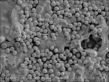
- FIG. 4A shows a scanning electron microscope image (SEM image) of an embodiment of the adhesive layer provided in the second separator.
- the second separator has a peel strength of 5 N / m to 75 N / m between the porous substrate and the heat resistant porous layer, and the heat resistant porous layer is less likely to be peeled off from the porous substrate.
- the adhesive layer provided in the second separator has a structure in which the adhesive resin particles adhere to the heat resistant porous layer or the porous substrate, so that the adhesive layer does not easily come off from the heat resistant porous layer or the porous substrate. Therefore, interface breakdown between the layers in the second separator is unlikely to occur, and as a result, it is assumed that the adhesive strength with the electrode as a whole is strong.
- FIGS. 5A-5D are each a schematic cross-sectional view of an example embodiment of a separator of the present disclosure.
- FIGS. 5A to 5D are schematic cross-sectional views mainly for explaining the stacking order of layers, and the structure of each layer is omitted or simplified.
- layers having similar functions are described with the same reference numerals.
- the heat resistant porous layer 30 is disposed on both sides of the porous substrate 20, and the adhesive layer is formed on both sides of the laminate 40 of the porous substrate 20 and the two heat resistant porous layers 30. 50 is a placed separator.
- the heat resistant porous layer 30 is disposed on both sides of the porous substrate 20, and the adhesive layer is formed on one side of the laminate 40 of the porous substrate 20 and the two heat resistant porous layers 30. 50 is a placed separator.
- the heat resistant porous layer 30 is disposed on one side of the porous substrate 20, and the adhesive layer is formed on both sides of the laminate 40 of the porous substrate 20 and one heat resistant porous layer 30. 50 is a placed separator.
- the heat resistant porous layer 30 is disposed on one side of the porous substrate 20, and the adhesive layer is formed on one side of the laminate 40 of the porous substrate 20 and one heat resistant porous layer 30.
- 50 is a placed separator. In the separator 10D, the adhesive layer 50 is disposed on the surface of the heat resistant porous layer 30.
- the heat resistant porous layer 30 is a layer disposed on the surface of the porous substrate 20.
- the heat resistant porous layer 30 may be on only one side of the porous substrate 20 or may be on both sides of the porous substrate 20.
- the heat resistance of the separator is more excellent, and the safety of the battery can be further enhanced.
- curling does not easily occur in the separator, and the handling property at the time of battery production is excellent.
- the heat resistant porous layer 30 is on only one side of the porous substrate 20, the ion permeability of the separator is more excellent.
- the thickness of the whole separator can be restrained and a battery with higher energy density can be manufactured.
- the adhesive layer 50 is a layer disposed on the surface of the porous substrate 20 or the heat resistant porous layer 30, and exists as the outermost layer of the separator.
- the adhesive layer 50 may be on only one side of the laminate 40 or may be on both sides of the laminate 40. When the adhesive layer 50 is present only on one side of the laminate 40, the adhesive layer 50 is preferably disposed on the surface of the heat resistant porous layer 30.
- the adhesion layer 50 may be disposed on one side or both sides of the laminate 40 in accordance with the composition or surface properties of the positive electrode or negative electrode of the battery. If the adhesive layer 50 is on only one side of the laminate 40, the thickness of the entire separator can be reduced, and a battery with higher energy density can be manufactured.
- the adhesive layer 50 is a layer in which the adhesive resin particles 52 adhere to the surface of the laminate 40.
- the adhesive layer 50 has a structure in which a large number of adhesive resin particles 52 are arranged adjacent to each other on the surface of the laminate 40, and the adhesive resin particles 52 are 1 in the thickness direction. It has a layer structure.
- the structure of the adhesive layer 50 is not limited to the above-described structure, and the adhesive resin particles 52 may have a structure in which a large number of the adhesive resin particles 52 are scattered on the surface of the laminate 40. It may have a structure in which a plurality of layers overlap in the direction.
- the adhesive layer 50 preferably has a structure in which a large number of adhesive resin particles 52 are arranged adjacent to each other on the surface of the laminate 40 from the viewpoint of being excellent in the adhesiveness to the electrode. From the viewpoint of enhancing, it is preferable that the adhesive resin particles 52 have a single layer structure in the thickness direction.
- a porous substrate means a substrate having pores or voids inside.
- a base material microporous membranes; porous sheets made of fibrous materials, such as nonwoven fabrics and paper; and the like can be mentioned.
- a microporous membrane is preferable from the viewpoint of thinning and strength of the separator.
- the microporous membrane means a membrane having a large number of micropores inside and connected to these micropores, and allowing gas or liquid to pass from one side to the other side. Do.
- the material of the porous substrate is preferably a material having electrical insulation, and may be either an organic material or an inorganic material.
- the porous substrate desirably contains a thermoplastic resin in order to provide the porous substrate with a shutdown function.
- the shutdown function is a function of blocking the movement of ions by blocking the pores of the porous substrate by dissolving the constituent material when the battery temperature rises, thereby preventing the thermal runaway of the battery.
- thermoplastic resin thermoplastic resins having a melting point of less than 200 ° C. are preferable.
- thermoplastic resin include polyesters such as polyethylene terephthalate; polyolefins such as polyethylene and polypropylene; and the like. Among them, polyolefins are preferable.
- a microporous membrane containing polyolefin As the porous substrate, a microporous membrane containing polyolefin (referred to as "polyolefin microporous membrane”) is preferable.
- polyolefin microporous membrane for example, a polyolefin microporous membrane applied to a conventional battery separator can be mentioned, and it is preferable to select one having sufficient mechanical properties and ion permeability from among them.
- the microporous polyolefin membrane is preferably a microporous membrane containing polyethylene from the viewpoint of exhibiting a shutdown function, and the content of polyethylene is preferably 95% by mass or more based on the total mass of the microporous polyolefin membrane.
- the microporous polyolefin film is preferably a microporous film containing polypropylene, from the viewpoint of providing heat resistance that does not easily rupture when exposed to high temperatures.
- the polyolefin microporous membrane is preferably a polyolefin microporous membrane containing polyethylene and polypropylene, from the viewpoint of providing a shutdown function and heat resistance that does not easily rupture when exposed to high temperature.
- a microporous polyolefin membrane a microporous membrane in which polyethylene and polypropylene are mixed in one layer can be mentioned.
- the microporous film preferably contains 95% by mass or more of polyethylene and 5% by mass or less of polypropylene from the viewpoint of achieving both a shutdown function and heat resistance.
- a polyolefin microporous film having a laminated structure of two or more layers, at least one layer containing polyethylene, and at least one layer containing polypropylene.
- the polyolefin contained in the microporous polyolefin membrane is preferably a polyolefin having a weight average molecular weight (Mw) of 100,000 to 5,000,000.
- Mw weight average molecular weight
- the Mw of the polyolefin is at least 100,000, sufficient mechanical properties can be imparted to the microporous membrane.
- the Mw of the polyolefin is 5,000,000 or less, the shutdown characteristics of the microporous membrane are good, and the microporous membrane can be easily formed.
- a method of producing a microporous polyolefin membrane a method of extruding a molten polyolefin resin from a T-die to form a sheet, crystallizing it, stretching it, and then heat treating it to form a microporous membrane: liquid paraffin etc.
- porous sheets made of fibrous materials include polyesters such as polyethylene terephthalate; polyolefins such as polyethylene and polypropylene; wholly aromatic polyamides, polyamideimides, polyimides, polyethersulfones, polysulfones, polyetherketones, polyetherimides, etc. And nonwoven sheets made of fibrous materials such as cellulose; and porous sheets such as paper.
- the properties of the porous base Various surface treatments may be applied as long as the As surface treatment, corona treatment, plasma treatment, flame treatment, ultraviolet irradiation treatment and the like can be mentioned.
- the thickness of the porous substrate is preferably 10.0 ⁇ m or less, more preferably 8.0 ⁇ m or less, from the viewpoint of enhancing the energy density of the battery, and 3.0 ⁇ m or more from the viewpoint of the production yield of the separator and the production yield of the battery. Is preferable, and 5.0 ⁇ m or more is more preferable.
- the Gurley value (JIS P8117: 2009) of the porous substrate is preferably 50 seconds / 100 mL to 400 seconds / 100 mL, and 50 seconds / 100 mL to 200 seconds from the viewpoint of suppressing short circuiting of the battery or obtaining sufficient ion permeability. / 100 mL is more preferable.
- the porosity of the porous substrate is preferably 20% to 60% from the viewpoint of obtaining an appropriate membrane resistance and a shutdown function.
- the piercing strength of the porous substrate is preferably 200 g or more from the viewpoint of the production yield of the separator and the production yield of the battery.
- the puncture strength of the porous base material is the maximum puncture load measured by performing a puncture test using a Kato Tech KES-G5 handy compression tester under a condition of a curvature of 0.5 mm at the tip of the needle and a puncture speed of 2 mm / sec. Point to (g).
- the heat-resistant porous layer in the first separator has a porous film containing at least one selected from the group consisting of wholly aromatic polyamide, polyamideimide and polyimide.
- the porous film is a film having a large number of micropores and gas or liquid can pass from one side to the other side.
- the porous film can be confirmed by a scanning electron microscope, and the outer surface of the heat resistant porous layer can be observed by observing the cross section of the separator or observing the outer surface of the heat resistant porous layer from the direction perpendicular to the surface. It can be observed that the resin part which has spread in the form of a film is formed, and that a large number of pores are formed in the resin part.
- a dense porous film having fine pores can be formed on a porous substrate by adjusting the composition of a coating liquid or a coagulating liquid in a wet coating method described later.
- the adhesive resin particles are attached to the porous film in a mode in which the adhesive layer is disposed on the surface of the heat resistant porous layer, Interfacial fracture between the heat resistant porous layer and the adhesive layer is unlikely to occur.
- the heat resistant porous layer has a porous film, the heat resistant porous layer is excellent in toughness, and cohesive failure of the heat resistant porous layer hardly occurs.
- the porous film is a fine film having fine pores, which forms the outer surface of the heat resistant porous layer.
- the average pore diameter of the micropores of the porous film is preferably 1000 nm or less, more preferably 800 nm or less, still more preferably 500 nm or less, from the viewpoint of the adhesive resin particles being difficult to peel off from the heat resistant porous layer Therefore, 1 nm or more is preferable, 5 nm or more is more preferable, and 10 nm or more is more preferable.
- the coverage of the porous film on the outer surface of the heat resistant porous layer is preferably 60% or more, more preferably 70% or more, and still more preferably 80% or more with respect to the area of the heat resistant porous layer in plan view.
- the wholly aromatic polyamide is suitable for the heat resistant porous layer from the viewpoint of durability.
- the wholly aromatic polyamide may be meta or para.
- meta-type wholly aromatic polyamides are preferable from the viewpoint of easily forming a porous layer and from the viewpoint of being excellent in redox resistance in electrode reaction.
- polymetaphenylene isophthalamide or polyparaphenylene terephthalamide is preferable as the wholly aromatic polyamide, and polymetaphenylene isophthalamide is more preferable.
- the weight average molecular weight of the wholly aromatic polyamide contained in the heat resistant porous layer is preferably 1 ⁇ 10 3 to 1 ⁇ 10 7, more preferably 5 ⁇ 10 3 to 5 ⁇ 10 6 , and 1 ⁇ 10 4 to 1 ⁇ 10 6 is more preferred.
- polyamideimide is suitable for the heat resistant porous layer from the viewpoint of heat resistance.
- the weight average molecular weight of the polyamideimide contained in the heat resistant porous layer is preferably 1 ⁇ 10 3 to 1 ⁇ 10 7, more preferably 5 ⁇ 10 3 to 5 ⁇ 10 6 , and 1 ⁇ 10 4 to 1 ⁇ 10 6 Is more preferred.
- polyimide is suitable for the heat resistant porous layer from the viewpoint of heat resistance.
- the polyimide may be an aliphatic polyimide or an aromatic polyimide.
- the weight average molecular weight of the polyimide contained in the heat resistant porous layer is preferably 1 ⁇ 10 3 to 1 ⁇ 10 7, more preferably 5 ⁇ 10 3 to 5 ⁇ 10 6 , and 1 ⁇ 10 4 to 1 ⁇ 10 6 More preferable.
- the heat resistant porous layer in the first separator may contain a heat resistant resin other than wholly aromatic polyamide, polyamide imide and polyimide.
- heat-resistant resins other than wholly aromatic polyamides, polyamideimides and polyimides include polysulfone, polyethersulfone, polyketone, polyetherketone, polyetherimide, cellulose, polyvinylidene fluoride resin and the like.
- One of these heat resistant resins may be used alone, or two or more thereof may be used in combination.
- the content of the heat resistant resin other than the wholly aromatic polyamide, the polyamideimide and the polyimide is to the total amount of all the resins contained in the heat resistant porous layer in order to maintain the effect of the wholly aromatic polyamide, the polyamideimide or the polyimide.
- 0% by mass to 50% by mass is preferable, 0% by mass to 40% by mass is more preferable, and 0% by mass to 30% by mass is more preferable.
- the total amount of the wholly aromatic polyamide, the polyamideimide and the polyimide contained in the heat resistant porous layer in the first separator is 50% by mass or more based on the total amount of all the resins contained in the heat resistant porous layer Is more preferably 70% by mass or more, and still more preferably 90% by mass or more.
- the heat resistant porous layer in the first separator preferably contains inorganic particles from the viewpoint of heat resistance.
- the inorganic particles are contained in the heat resistant porous layer, for example, in a state bound and covered by the porous film.
- the inorganic particles include particles of metal hydroxides such as aluminum hydroxide, magnesium hydroxide, calcium hydroxide, chromium hydroxide, zirconium hydroxide, cerium hydroxide, nickel hydroxide and boron hydroxide; silica, alumina And particles of metal oxides such as zirconia and magnesium oxide; particles of carbonate such as calcium carbonate and magnesium carbonate; particles of sulfate such as barium sulfate and calcium sulfate; and the like.
- metal hydroxide particles or metal oxide particles are preferable from the viewpoint of the stability to the electrolytic solution and the electrochemical stability.
- the inorganic particles may be surface-modified by a silane coupling agent or the like.
- the particle shape of the inorganic particles is not limited, and may be spherical, elliptical, plate-like, needle-like or amorphous.
- the inorganic particles contained in the heat resistant porous layer are preferably plate-like particles or primary particles which are not aggregated, from the viewpoint of suppressing a short circuit of the battery.
- the inorganic particles may be used alone or in combination of two or more.
- the volume average particle size of the inorganic particles is preferably 0.01 ⁇ m to 10 ⁇ m.
- the lower limit thereof is more preferably 0.1 ⁇ m or more, and the upper limit thereof is more preferably 5 ⁇ m or less.
- the particle size distribution of the inorganic particles is preferably 0.1 ⁇ m ⁇ d90 ⁇ d10 ⁇ 3 ⁇ m.
- d10 represents the 10% cumulative particle size ( ⁇ m) in the volume-based particle size distribution calculated from the small particle side
- d90 represents 90% cumulative particle size in the volume-based particle size distribution calculated from the small particle side It represents the diameter ( ⁇ m).
- the particle size distribution is measured, for example, using a laser diffraction type particle size distribution measuring apparatus (for example, Sysmex Corporation, Mastersizer 2000), using water as a dispersion medium and nonionic surfactant Triton X-100 as a dispersing agent. It is performed using a small amount.
- the mass ratio of the inorganic particles in the heat-resistant porous layer is preferably 50% by mass or more and 55% by mass or more from the viewpoint of heat resistance. 60 mass% or more is more preferable.
- the mass ratio of the inorganic particles in the heat resistant porous layer is preferably 90% by mass or less, more preferably 85% by mass or less, and further preferably 80% by mass or less from the viewpoint that the heat resistant porous material hardly peels off from the porous substrate. preferable.
- the heat resistant porous layer in the first separator may contain an organic filler.
- the organic filler is, for example, contained in the heat resistant porous layer in a state of being bound and covered by the porous film.
- organic filler for example, crosslinked poly (meth) acrylic acid, crosslinked poly (meth) acrylic acid ester, crosslinked polysilicone, crosslinked polystyrene, crosslinked polydivinylbenzene, styrene-divinylbenzene copolymer crosslinked product, melamine resin, phenol Particles made of crosslinked polymers such as resins and benzoguanamine-formaldehyde condensates; particles made of heat-resistant polymers such as polysulfones, polyacrylonitriles, aramids and polyacetals;
- One of these organic fillers may be used alone, or two or more of these organic fillers may be used in combination.
- the heat resistant porous layer in the first separator may contain an additive such as a dispersant such as a surfactant, a wetting agent, an antifoaming agent, and a pH adjuster.
- a dispersing agent is added to the coating liquid for forming a heat resistant porous layer in order to improve dispersibility, coating property, or storage stability.
- the wetting agent, the antifoaming agent, and the pH adjusting agent may be added to the coating liquid for forming the heat resistant porous layer, for example, for the purpose of improving the compatibility with the porous substrate, and the air biting to the coating liquid It is added for the purpose of suppressing, or for the purpose of pH adjustment.
- the heat resistant porous layer in the second separator contains a heat resistant resin having at least one of an amide bond and an imide bond in the molecule, and / or inorganic particles.
- the heat resistant porous layer has a large number of micropores, and gas or liquid can pass from one side to the other side.
- a heat resistant resin having at least one of an amide bond and an imide bond in a molecule is referred to as a "specified heat resistant resin”.
- the specific heat-resistant resin in the heat-resistant porous layer may form a fibril-like or porous film (details will be described later) to form a three-dimensional network structure, and is a binder resin for connecting inorganic particles May be included.
- the specific heat resistant resin in the heat resistant porous layer may be resin particles, and the resin particles of the specific heat resistant resin are connected to each other, or the resin particles of the specific heat resistant resin are connected to the inorganic particles, It may form a texture layer.
- heat resistant resin which has at least one of an amide bond and an imide bond in a molecule
- wholly aromatic polyamide, a polyamide imide, a polyimide, a polyether imide etc. are mentioned, for example.
- One of these resins may be used alone, or two or more thereof may be used in combination.
- the weight-average molecular weight of the specific heat-resistant resin contained in the heat-resistant porous layer is preferably 1 ⁇ 10 3 to 1 ⁇ 10 7, more preferably 5 ⁇ 10 3 to 5 ⁇ 10 6 , 1 ⁇ 10 4 to 1 ⁇ 10 6 is more preferred.
- wholly aromatic polyamides are preferable from the viewpoint of durability.
- the wholly aromatic polyamide may be meta or para.
- meta-type wholly aromatic polyamides are preferable from the viewpoint of easily forming a porous layer and from the viewpoint of being excellent in redox resistance in electrode reaction.
- polymetaphenylene isophthalamide or polyparaphenylene terephthalamide is preferable as the wholly aromatic polyamide, and polymetaphenylene isophthalamide is more preferable.
- the weight average molecular weight of the wholly aromatic polyamide contained in the heat resistant porous layer is preferably 1 ⁇ 10 3 to 1 ⁇ 10 7, more preferably 5 ⁇ 10 3 to 5 ⁇ 10 6 , and 1 ⁇ 10 4 to 1 ⁇ 10 6 is more preferred.
- the heat resistant porous layer in the second separator may contain a heat resistant resin other than the specific heat resistant resin.
- the heat resistant resin other than the specific heat resistant resin include polysulfone, polyether sulfone, polyketone, polyether ketone, cellulose, polyvinylidene fluoride resin and the like. One of these heat resistant resins may be used alone, or two or more thereof may be used in combination.
- the content of the heat resistant resin other than the specific heat resistant resin is preferably 0% by mass to 50% by mass with respect to the total amount of all the resins contained in the heat resistant porous layer in order to maintain the effect of the specific heat resistant resin. 0% by mass to 40% by mass is more preferable, and 0% by mass to 30% by mass is even more preferable.
- the total amount of the specific heat resistant resin contained in the heat resistant porous layer is the total amount of all the resins contained in the heat resistant porous layer.
- the content is preferably 50% by mass or more, more preferably 70% by mass or more, and still more preferably 90% by mass or more.
- the heat resistant porous layer in the second separator may not contain the specific heat resistant resin.
- the heat resistant porous layer contains inorganic particles and a binder resin (for example, an acrylic resin).
- the heat resistant porous layer in the second separator preferably contains inorganic particles from the viewpoint of heat resistance.
- the inorganic particles include particles of metal hydroxides such as aluminum hydroxide, magnesium hydroxide, calcium hydroxide, chromium hydroxide, zirconium hydroxide, cerium hydroxide, nickel hydroxide and boron hydroxide; silica, alumina And particles of metal oxides such as zirconia and magnesium oxide; particles of carbonate such as calcium carbonate and magnesium carbonate; particles of sulfate such as barium sulfate and calcium sulfate; and the like.
- metal hydroxide particles or metal oxide particles are preferable from the viewpoint of the stability to the electrolytic solution and the electrochemical stability.
- the inorganic particles may be surface-modified by a silane coupling agent or the like.
- the particle shape of the inorganic particles is not limited, and may be spherical, elliptical, plate-like, needle-like or amorphous.
- the inorganic particles contained in the heat resistant porous layer are preferably plate-like particles or primary particles which are not aggregated, from the viewpoint of suppressing a short circuit of the battery.
- the inorganic particles may be used alone or in combination of two or more.
- the volume average particle size of the inorganic particles is preferably 0.01 ⁇ m to 10 ⁇ m.
- the lower limit thereof is more preferably 0.1 ⁇ m or more, and the upper limit thereof is more preferably 5 ⁇ m or less.
- the particle size distribution of the inorganic particles is preferably 0.1 ⁇ m ⁇ d90 ⁇ d10 ⁇ 3 ⁇ m.
- d10 represents the 10% cumulative particle size ( ⁇ m) in the volume-based particle size distribution calculated from the small particle side
- d90 represents 90% cumulative particle size in the volume-based particle size distribution calculated from the small particle side It represents the diameter ( ⁇ m).
- the particle size distribution is measured, for example, using a laser diffraction type particle size distribution measuring apparatus (for example, Sysmex Corporation, Mastersizer 2000), using water as a dispersion medium and nonionic surfactant Triton X-100 as a dispersing agent. It is performed using a small amount.
- the mass ratio of the inorganic particles in the heat resistant porous layer is preferably 50% by mass or more and 55% by mass or more from the viewpoint of heat resistance. 60 mass% or more is more preferable.
- the mass ratio of the inorganic particles in the heat resistant porous layer is preferably 90% by mass or less, more preferably 85% by mass or less, and further preferably 80% by mass or less from the viewpoint that the heat resistant porous material hardly peels off from the porous substrate. preferable.
- the heat resistant porous layer in the second separator preferably contains at least a specific heat resistant resin, and preferably further contains inorganic particles.
- the heat resistant porous layer in the second separator preferably has a porous film containing a specific heat resistant resin.
- the porous film is a film having a large number of micropores and gas or liquid can pass from one side to the other side.
- the porous film can be confirmed by a scanning electron microscope, and the outer surface of the heat resistant porous layer can be observed by observing the cross section of the separator or observing the outer surface of the heat resistant porous layer from the direction perpendicular to the surface. It can be observed that the resin part which has spread in the form of a film is formed, and that a large number of pores are formed in the resin part.
- a dense porous film having fine pores can be formed on a porous substrate by adjusting the composition of a coating liquid or a coagulating liquid in a wet coating method described later.
- Examples of the form of the heat resistant porous layer having a porous coating include the following forms (a ') to (d'). Preferred embodiments (type, molecular weight, size, shape, etc.) of the specific heat-resistant resin and the inorganic particles in the forms (a ′) to (d ′) are as described above.
- the heat resistant porous layer is a porous film itself containing a specific heat resistant resin.
- the heat resistant porous layer contains an inner layer containing a specific heat resistant resin formed on a porous substrate, and a specific heat resistant resin formed so as to cover the outer surface of the inner layer And a porous coating.
- the inner layer is a porous structure that is larger in diameter than the porous coating.
- the heat resistant porous layer as a whole exhibits a so-called skin-core structure.
- a heat resistant porous layer is a layer further containing inorganic particles, wherein the inorganic particles are bound and covered with a porous film containing a specific heat resistant resin.
- the heat resistant porous layer as a whole exhibits a so-called skin-core structure.
- FIG. 4B is a SEM image of the outer surface (surface remote from the porous substrate) of the heat resistant porous layer
- FIG. 4C is a SEM image of a cross section of the heat resistant porous layer and the porous substrate.
- the porous film is a film forming the outer surface of the heat resistant porous layer, and is a fine film having fine pores.
- the adhesive resin particles adhere to the porous film in the form in which the adhesive layer is disposed on the surface of the heat resistant porous layer. As a result, interface failure between the heat resistant porous layer and the adhesive layer is less likely to occur.
- the heat resistant porous layer has a porous film, the heat resistant porous layer is excellent in toughness, and cohesive failure of the heat resistant porous layer hardly occurs.
- the heat resistant porous layer in the second separator may contain an organic filler.
- the organic filler is contained in the heat resistant porous layer, for example, in a state of being bound by a specific heat resistant resin, or in a state of being bound and covered by a porous film.
- organic filler for example, crosslinked poly (meth) acrylic acid, crosslinked poly (meth) acrylic acid ester, crosslinked polysilicone, crosslinked polystyrene, crosslinked polydivinylbenzene, styrene-divinylbenzene copolymer crosslinked product, melamine resin, phenol Particles made of crosslinked polymers such as resins and benzoguanamine-formaldehyde condensates; particles made of heat-resistant polymers such as polysulfones, polyacrylonitriles, aramids and polyacetals;
- One of these organic fillers may be used alone, or two or more of these organic fillers may be used in combination.
- the heat resistant porous layer in the second separator may contain an additive such as a dispersant such as a surfactant, a wetting agent, an antifoaming agent, and a pH adjuster.
- a dispersing agent is added to the coating liquid for forming a heat resistant porous layer in order to improve dispersibility, coating property, or storage stability.
- the wetting agent, the antifoaming agent, and the pH adjusting agent may be added to the coating liquid for forming the heat resistant porous layer, for example, for the purpose of improving the compatibility with the porous substrate, and the air biting to the coating liquid It is added for the purpose of suppressing, or for the purpose of pH adjustment.
- the thickness of the heat-resistant porous layer is preferably 0.5 ⁇ m or more on one side, more preferably 1.0 ⁇ m or more on one side, from the viewpoint of heat resistance or handling of the separator. From the viewpoint of energy density, one surface is preferably 5.0 ⁇ m or less, and more preferably 4.0 ⁇ m or less.
- the heat-resistant porous layer preferably has a thickness of 1.0 ⁇ m or more, 2.0 ⁇ m or more, as the total of both sides, whether the heat-resistant porous layer is on only one side or both sides of the porous substrate. More preferably, 10.0 ⁇ m or less is preferable, and 8.0 ⁇ m or less is more preferable.
- the weight of the heat-resistant porous layer is preferably 1.0 g / m 2 or more, more preferably 2.0 g / m 2 or more, as the sum of both surfaces, from the viewpoint of heat resistance or handling of the separator. From the viewpoint of the handling property of the separator or the energy density of the battery, 10.0 g / m 2 or less is preferable, and 8.0 g / m 2 or less is more preferable.
- the porosity of the heat resistant porous layer is preferably 40% or more, more preferably 50% or more, still more preferably 60% or more, from the viewpoint of ion permeability of the separator From the viewpoint of the properties, 90% or less is preferable, 80% or less is more preferable, and 70% or less is more preferable.
- the method of determining the porosity of the heat resistant porous layer is the same as the method of determining the porosity of the porous substrate.
- the peel strength between the porous substrate and the heat resistant porous layer is preferably 5 N / m or more, more preferably 10 N / m or more, and 15 N / m from the viewpoint of the adhesive strength of the separator to the electrode. m or more is further preferable, and 20 N / m or more is further preferable. From the viewpoint of ion permeability, the peel strength is preferably 75 N / m or less, more preferably 60 N / m or less, and still more preferably 50 N / m or less.
- the peel strength between the porous substrate and the heat resistant porous layer is in the above range on both sides of the porous substrate. Is preferred.
- the adhesive layer has a structure in which adhesive resin particles are attached to one side or both sides of a laminate of a porous substrate and a heat resistant porous layer.
- the adhesive layer allows gas or liquid to pass from one surface to the other surface by the gaps present between the adhesive resin particles.
- the structure in which the adhesive resin particles are attached means that in the completed separator, not only the aspect in which the resin retains the particle shape, but also the heat treatment or drying treatment in the completed separator using the resin particles as the material of the adhesive layer.
- the embodiment also includes an aspect in which the resin particles are partially melted and not retaining the particle shape.
- the adhesive layer has a structure in which the adhesive resin particles are attached to the heat resistant porous layer or the porous substrate, interfacial failure between the heat resistant porous layer or the porous substrate and the adhesive layer occurs. Hateful. Further, since the adhesive layer has a structure in which the adhesive resin particles adhere to and are connected to each other, the adhesive layer is excellent in toughness, and cohesive failure of the adhesive layer does not easily occur.
- the adhesive resin particles are particulate resin having adhesiveness to the electrode of the battery.
- the adhesive resin particles may be selected in accordance with the composition of the positive electrode or the negative electrode.
- the adhesive resin particles are preferably resin particles that are stable to the electrolytic solution and are also electrochemically stable.
- the adhesive resin particles for example, homopolymers or copolymers of polyvinylidene fluoride resin, fluorocarbon rubber, acrylic resin, styrene-butadiene copolymer, vinyl nitrile compound (acrylonitrile, methacrylonitrile, etc.),
- examples include particles containing carboxymethyl cellulose, hydroxyalkyl cellulose, polyvinyl alcohol, polyvinyl butyral, polyvinyl pyrrolidone, polyether (polyethylene oxide, polypropylene oxide, etc.), or a mixture of two or more of these.
- particles containing polyvinylidene fluoride resin and / or acrylic resin are preferable from the viewpoint of being excellent in oxidation resistance.
- polyvinylidene fluoride resins homopolymers of vinylidene fluoride (that is, polyvinylidene fluoride); copolymers of vinylidene fluoride and other monomers (polyvinylidene fluoride copolymers); polyvinylidene fluoride and polyvinylidene fluoride Mixtures of copolymers.
- a monomer copolymerizable with vinylidene fluoride for example, tetrafluoroethylene, hexafluoropropylene, trifluoroethylene, chlorotrifluoroethylene, trichloroethylene, vinyl fluoride, trifluoroperfluoropropyl ether, ethylene, (meth) acrylic Acids, methyl (meth) acrylate, (meth) acrylic esters, vinyl acetate, vinyl chloride, acrylonitrile and the like can be mentioned.
- One of these monomers may be used alone, or two or more thereof may be used in combination.
- the polyvinylidene fluoride copolymer contained in the adhesive resin particles is a copolymer having 50 mol% or more of a constituent unit derived from vinylidene fluoride from the viewpoint of obtaining mechanical strength that can withstand pressure and heating at the time of battery production. Is preferred.
- the polyvinylidene fluoride copolymer contained in the adhesive resin particles may be a copolymer of vinylidene fluoride and tetrafluoroethylene, a copolymer of vinylidene fluoride and hexafluoropropylene, or a copolymer of vinylidene fluoride and trifluoroethylene.
- a polymer is preferred, and a copolymer of vinylidene fluoride and hexafluoropropylene is more preferred.
- a copolymer containing 0.1 mol% to 10 mol% (preferably 0.5 mol% to 5 mol%) of a constituent unit derived from hexafluoropropylene is preferable .
- the weight-average molecular weight of the polyvinylidene fluoride or polyvinylidene fluoride copolymer contained in the adhesive resin particles is preferably 1,000 to 5,000,000, more preferably 10,000 to 3,000,000, and still more preferably 50,000 to 2,000,000.
- acrylic resin contained in adhesive resin particles for example, poly (meth) acrylic acid, poly (meth) acrylate, poly (meth) acrylic ester, crosslinked poly (meth) acrylic acid, crosslinked poly (meth) Acrylates, crosslinked poly (meth) acrylates, etc. may be mentioned, and modified acrylic resins may be used. One of these may be used alone, or two or more may be used in combination.
- the acrylic resin may be used as a mixture of polyvinylidene fluoride and acrylic resin or a mixture of polyvinylidene fluoride copolymer and acrylic resin.
- polyvinylidene fluoride particles polyvinylidene fluoride copolymer particles, particles of a mixture of polyvinylidene fluoride and a polyvinylidene fluoride copolymer, particles of a mixture of polyvinylidene fluoride and an acrylic resin, or polyfluoride Particles of a mixture of vinylidene copolymer and acrylic resin are preferred.
- polyvinylidene fluoride copolymer a copolymer of vinylidene fluoride and tetrafluoroethylene, a copolymer of vinylidene fluoride and hexafluoropropylene, or a copolymer of vinylidene fluoride and trifluoroethylene is preferable.
- the mixture of polyvinylidene fluoride and acrylic resin constituting the adhesive resin particles, or the mixture of polyvinylidene fluoride copolymer and acrylic resin is polyvinylidene fluoride or polyvinylidene fluoride copolymer from the viewpoint of oxidation resistance. It is preferable to contain 20 mass% or more.
- adhesive resin particles two or more types of adhesive resin particles may be used in combination. From the viewpoint of controlling the ion permeability of the adhesive layer, the adhesiveness of the adhesive layer to the electrode, the peel strength between the adhesive layer and the heat resistant porous layer, and the handling property of the adhesive layer in a balanced manner, polyvinylidene fluoride resin It is preferable to use a mixture of a first adhesive resin particle containing the above and a second adhesive resin particle containing the acrylic resin.
- the first adhesive resin particles (hereinafter also referred to as “resin particles F”) are particles containing a polyvinylidene fluoride resin in an amount of more than 50% by mass relative to the total solid content.
- the second adhesive resin particles (hereinafter also referred to as “resin particles A”) are particles containing an acrylic resin in an amount of more than 50% by mass relative to the total solid content.
- polyvinylidene fluoride-based resin contained in the resin particle F examples include polyvinylidene fluoride, polyvinylidene fluoride copolymer, and a mixture of polyvinylidene fluoride and polyvinylidene fluoride copolymer. Preferred embodiments of these polymers are as described above. It is.
- the resin particle F may contain another resin other than the polyvinylidene fluoride resin.
- the amount of the polyvinylidene fluoride resin contained in the resin particle F is more than 50% by mass, preferably 70% by mass or more, and more preferably 90% by mass or more with respect to the total solid content of the resin particle F It is more preferably 100% by mass.
- acrylic resin which resin particle A contains, poly (meta) acrylic acid, poly (meta) acrylic acid salt, poly (meta) acrylic acid ester, crosslinked poly (meta) acrylic acid, crosslinked poly (meta) acrylic, for example Acid salts, crosslinked poly (meth) acrylic acid esters, etc. may be mentioned, and modified acrylic resins may be used. One of these may be used alone, or two or more may be used in combination.
- the resin particle A may contain another resin other than the acrylic resin.
- the amount of the acrylic resin contained in the resin particle A is more than 50% by mass, preferably 70% by mass or more, and more preferably 90% by mass or more based on the total solid content of the resin particle A. More preferably, it is 100 mass%.
- the mass ratio of the resin particles F to the resin particles A contained in the adhesive layer may be adjusted according to the characteristics required for the adhesive layer.
- the mixture of the resin particles F and the resin particles A is preferably a dispersion liquid in which the resin particles F and the resin particles A are dispersed in a dispersion medium as a coating liquid used for producing the adhesive layer.
- the dispersion medium of the dispersion liquid is not particularly limited as long as it is a dispersion medium which does not dissolve polyvinylidene fluoride resin, acrylic resin and heat resistant porous layer, but water is preferable for safety in handling. That is, the dispersion liquid is preferably an aqueous dispersion liquid in which the resin particles F and the resin particles A are dispersed in water.
- the aqueous dispersion in which the resin particles F and the resin particles A are dispersed in water may be prepared by dispersing the resin particles F and the resin particles A in water, and the aqueous dispersion in which the resin particles F are dispersed in water may be prepared in water You may mix and prepare the aqueous dispersion in which the resin particle A disperse
- aqueous dispersion in which resin particles F are dispersed in water a known aqueous dispersion containing a commercial product can be used, or a known resin particle F containing a commercial product can be dispersed in water and used .
- Typical commercial products of the aqueous dispersion in which resin particles F are dispersed in water include, for example, LBG2200LX, LATEX32, KYNAR WATERBORNE RC series (RC-10246, RC-10278, RC-10280, etc.) manufactured by Arkema; Solvay Specific examples include XPH 838 series, XPH 882 series, XPH 883 series, XPH 884 series, XPH 859 series, XPH 918 series, etc. manufactured by Special Polymers, Inc .; PVDF aqueous dispersion manufactured by Kureha;
- aqueous dispersion in which the resin particles A are dispersed in water a known aqueous dispersion containing a commercial product can be used, or a known resin particle A containing a commercial product can be dispersed in water and used .
- a typical commercial item of the aqueous dispersion in which the resin particles A are dispersed in water for example, BM-120S or the like manufactured by Zeon Corporation; an acrylic particle aqueous dispersion manufactured by DIC; and the like can be mentioned.
- the volume average particle diameter of the adhesive resin particles is preferably 0.01 ⁇ m or more, more preferably 0.03 ⁇ m or more, still more preferably 0.05 ⁇ m or more, and the thickness of the adhesive layer from the viewpoint of forming a good porous structure. From the viewpoint of suppressing, 1.0 ⁇ m or less is preferable, 0.8 ⁇ m or less is more preferable, and 0.6 ⁇ m or less is more preferable.
- the adhesive layer may contain components other than the adhesive resin particles, as long as the effects of the present disclosure are not impaired.
- the component include additives added to a resin particle dispersion for forming an adhesive layer.
- the adhesive resin particles preferably occupy 90% by mass or more of the total amount of the layer, and more preferably the adhesive resin particles occupy 95% by mass or more. More preferably, the adhesive layer contains substantially only adhesive resin particles.
- the adhesive layer may contain an additive such as a dispersant such as a surfactant, a wetting agent, an antifoaming agent, and a pH adjuster.
- a dispersant such as a surfactant, a wetting agent, an antifoaming agent, and a pH adjuster.
- the dispersant is added to the resin particle dispersion for forming the adhesive layer for the purpose of improving the dispersibility, the coatability or the storage stability.
- the wetting agent, the antifoaming agent, and the pH adjusting agent are, for example, for the purpose of improving the compatibility with the heat resistant porous layer, the resin particle dispersion for forming the adhesive layer, and the air entrapment to the resin particle dispersion. It is added for the purpose of suppressing, or for the purpose of pH adjustment.
- Examples of the surfactant contained in the resin particle dispersion for forming the adhesive layer include non-reactive alkyl sulfates, polyoxyethylene alkyl ether sulfates, alkyl benzene sulfonates, alkyl naphthalene sulfonates.
- the anionic surfactant which is a reactive surfactant includes, for example, an ethylenically unsaturated monomer having a group selected from a sulfonic acid group, a sulfonate group, a sulfuric acid ester group and a salt thereof, and a sulfonic acid It is preferable that it is a compound which has group (namely, ammonium sulfonate group or alkali metal sulfonate group) which is group or its ammonium salt or alkali metal salt.
- Examples thereof include polyoxyethylene sulfuric acid ester salts, and sulfuric acid ester salts of polyoxyethylene polyoxybutylene (3-methyl-3-butenyl) ether.
- nonionic surfactant which is a reactive surfactant
- examples of the nonionic surfactant which is a reactive surfactant include ⁇ - [1-[(allyloxy) methyl] -2- (nonylphenoxy) ethyl] - ⁇ -hydroxypolyoxyethylene, polyoxyethylene alkylpropenyl And phenyl ether, ⁇ - [2-[(allyloxy) -1- (alkyloxymethyl) ethyl] - ⁇ -hydroxypolyoxyethylene, polyoxyethylene polyoxybutylene (3-methyl-3-butenyl) ether.
- the surfactant may be used alone or in combination of two or more.
- the adhesive layer further contains a surfactant.
- the surfactant contained in the adhesive layer comprises a non-reactive anionic surfactant, a non-reactive nonionic surfactant, a reactive anionic surfactant and a reactive nonionic surfactant. At least one selected from the group is preferred. Specific examples of the non-reactive anionic surfactant, the non-reactive nonionic surfactant, the reactive anionic surfactant, and the reactive nonionic surfactant include forming an adhesive layer.
- the mass ratio of the surfactant to the total mass of the adhesive layer is preferably 0.1% by mass to 10% by mass, and more preferably 1% by mass to 8% by mass.
- the weight of the adhesive layer is preferably 0.2 g / m 2 or more, more preferably 0.25 g / m 2 or more, still more preferably 0.3 g / m 2 or more, per one surface, from the viewpoint of adhesion to the electrode. From the viewpoint of permeability, handleability of the separator or energy density of the battery, per side, 2.0 g / m 2 or less is preferable, 1.8 g / m 2 or less is more preferable, and 1.6 g / m 2 or less is still more preferable .
- the coverage of the adhesive resin particles in the adhesive layer is obtained by imaging the surface of the separator from the direction perpendicular to the surface by a scanning electron microscope, randomly identifying 10 square areas, and determining the coverage of each area, and further 10 Calculated by calculating the average value of points.
- the thickness of the separator of the present disclosure is preferably 8.0 ⁇ m or more, more preferably 9.0 ⁇ m or more from the viewpoint of mechanical strength of the separator, and preferably 20.0 ⁇ m or less from the viewpoint of battery energy density; 0 ⁇ m or less is more preferable.
- the piercing strength of the separator of the present disclosure is preferably 150 g to 1000 g, more preferably 200 g to 600 g, from the viewpoint of mechanical strength of the separator or short circuit resistance of the battery.
- the method of measuring the puncture strength of the separator is the same as the method of measuring the puncture strength of the porous substrate.
- the porosity of the separator of the present disclosure is preferably 30% to 60% from the viewpoint of adhesion to the electrode, handleability of the separator, ion permeability or mechanical strength.
- the film resistance of the separator of the present disclosure in view of the load characteristics of the battery, preferably 0.5ohm ⁇ cm 2 ⁇ 10ohm ⁇ cm 2, more preferably 1ohm ⁇ cm 2 ⁇ 8ohm ⁇ cm 2.
- the Gurley value (JIS P8117: 2009) of the separator of the present disclosure is preferably 50 seconds / 100 mL to 800 seconds / 100 mL, and 80 seconds / 100 mL to 500 seconds / 100 mL. More preferably, 100 seconds / 100 mL to 400 seconds / 100 mL are more preferable.
- the separator of the present disclosure has a value obtained by subtracting the Gurley value of the porous substrate from the Gurley value of the separator (in the state where the heat resistant porous layer and the adhesive layer are formed on the porous substrate). 300 sec / 100 mL or less is preferable, 200 sec / 100 mL or less is more preferable, and 150 sec / 100 mL or less is still more preferable.
- the lower limit of the value obtained by subtracting the Gurley value of the porous substrate from the Gurley value of the separator is preferably 20 seconds / 100 mL or more from the viewpoint of providing adhesive resin particles in an amount sufficient for adhesion to the electrode.
- Tensile strength in the MD direction of the separator of the present disclosure in view of mechanical strength or handling properties of the separator (fixing of the adhesive layer) is preferably 500 kgf / cm 2 or more, 600 kgf / cm 2 or more, more preferably, 700 kgf / More preferably, cm 2 or more. From the above viewpoint, the tensile strength in the MD direction is preferably as high as possible, but is usually 3000 kgf / cm 2 or less.
- Tensile strength in the TD direction of the separator of the present disclosure in view of mechanical strength or handling properties of the separator (fixing of the adhesive layer) is preferably 500 kgf / cm 2 or more, 600 kgf / cm 2 or more, more preferably, 700 kgf / More preferably, cm 2 or more. From the above viewpoint, the tensile strength in the TD direction is preferably as high as possible, but is usually 3,000 kgf / cm 2 or less.
- the tensile strength of the separator of the present disclosure depends on, for example, the content of inorganic particles in the heat resistant porous layer, the thickness of the heat resistant porous layer, the porosity of the heat resistant porous layer, the thickness of the adhesive layer, etc. It can control.
- the first separator is produced, for example, by the following production method A or production method B.
- Production method B may be any of the following forms B-1 to B-4.
- the heat resistant porous layer is formed on the porous substrate by a wet coating method.
- the second separator is produced, for example, by the following production method A or production method B.
- the heat resistant porous layer may be formed by a wet coating method or a dry coating method.
- Production method B may be any of the following forms B-1 to B-7.
- Forms B-1 to B-4 are forms in which the heat resistant porous layer is formed by a wet coating method.
- the heat resistant porous layer is formed by a dry coating method.
- the wet coating method is a method of solidifying the coating layer in the coagulating liquid
- the dry coating method is a method of drying the coating layer to solidify the coating layer
- Production method A (discontinuous production method): A heat resistant porous layer was formed on a porous substrate drawn from a roll to obtain a laminate of the porous substrate and the heat resistant porous layer After that, once, the laminate is wound on another roll. Next, an adhesive layer is formed on the laminate drawn from the roll to obtain a separator, and the finished separator is wound on another roll.
- Production Method B Continuous Production Method: A heat resistant porous layer and an adhesive layer are formed continuously or simultaneously on a porous substrate drawn from a roll, and the finished separator is wound on another roll. take.
- Form B-1 A coating liquid for forming a heat resistant porous layer is coated on a porous base material, immersed in a coagulating liquid to solidify the coated layer, and removed from the coagulating liquid, washed with water and dried, and then The adhesive resin particle dispersion is applied and dried.
- Form B-2 A coating liquid for forming a heat resistant porous layer is coated on a porous base material, immersed in a coagulating liquid to solidify the coated layer, and removed from the coagulating liquid and washed with water, and then adhesion Of the water-soluble resin particle dispersion and drying.
- Form B-3 The heat resistant porous layer-forming coating solution and the adhesive resin particle dispersion are simultaneously coated in two layers on a porous substrate, and immersed in a coagulating solution to solidify the former coated layer , Lifting from the coagulating solution, washing with water and drying.
- Form B-4 A coating liquid for forming a heat resistant porous layer is coated on a porous base material, immersed in a coagulating liquid to solidify the coated layer, withdrawn from the coagulating liquid, and containing adhesive resin particles Washing with water and adhesion of adhesive resin particles are carried out by conveying the water bath, and it is pulled up and dried from the water bath.
- Form B-5 A coating liquid for forming a heat resistant porous layer is coated on a porous substrate and dried, and then an adhesive resin particle dispersion is coated and dried.
- Form B-6 A heat resistant porous layer-forming coating solution is applied on a porous substrate, and then an adhesive resin particle dispersion is applied and dried.
- Form B-7 The heat resistant porous layer-forming coating solution and the adhesive resin particle dispersion are simultaneously coated in two layers on a porous substrate and dried.
- a heat resistant porous layer is formed on at least one surface of the porous substrate by a wet coating method to obtain a laminate of the porous substrate and the heat resistant porous layer. Then, an adhesive layer is formed on at least one surface of the laminate by a dry coating method.
- the manufacturing method B of form B-1 includes the following steps (1) to (7), and the steps (1) to (7) are sequentially performed.
- Step (1) Preparation of Coating Liquid for Forming Heat-Resistant Porous Layer When Manufacturing a First Separator, Coating Liquid for Forming Heat-Resistant Porous Layer (hereinafter referred to as “coating liquid” in the description of the manufacturing method Is prepared by dissolving at least one selected from the group consisting of wholly aromatic polyamide, polyamideimide and polyimide in a solvent. In the coating liquid, inorganic particles or other components are dispersed or dissolved as necessary.
- the coating liquid for forming a heat resistant porous layer dissolves the specific heat resistant resin and / or the inorganic particles in a solvent Or make it disperse.
- coating liquid dissolves the specific heat resistant resin and / or the inorganic particles in a solvent Or make it disperse.
- a resin other than the specific heat resistant resin, or other components other than the resin is dissolved or dispersed.
- the solvent used to prepare the coating liquid is a solvent that dissolves at least one selected from the group consisting of wholly aromatic polyamide, polyamideimide, and polyimide (hereinafter also referred to as “good solvent” .)including.
- good solvent polar amide solvents such as N-methyl pyrrolidone, dimethyl acetamide, dimethylformamide, dimethylformamide and the like can be mentioned.
- the solvent used for preparation of a coating liquid contains the solvent (Hereinafter, it is also mentioned a "good solvent.") Which melt
- polar amide solvents such as N-methyl pyrrolidone, dimethyl acetamide, dimethylformamide, dimethylformamide and the like can be mentioned.
- the solvent used for preparation of a coating liquid contains the phase-separation agent which induces phase separation from a viewpoint of forming the porous layer which has a favorable porous structure. Therefore, it is preferable that the solvent used for preparation of a coating liquid is a mixed solvent of a good solvent and a phase separation agent.
- the phase separation agent is preferably mixed with the good solvent in an amount that can ensure an appropriate viscosity for coating. Examples of phase separation agents include water, methanol, ethanol, propyl alcohol, butyl alcohol, butanediol, ethylene glycol, propylene glycol, tripropylene glycol and the like.
- a solvent used for preparation of a coating liquid it is a mixed solvent of a good solvent and a phase-separating agent from a viewpoint of forming a favorable porous structure, Comprising: 60 mass% or more of a good solvent is contained, and a phase-separating agent is 40% Mixed solvents containing at most% are preferred.
- the resin concentration of the wholly aromatic polyamide, the polyamideimide and the polyimide in the coating liquid is 1% by mass to 20% by mass from the viewpoint of forming a good porous structure. preferable.
- the resin concentration of the coating liquid is preferably 1% by mass to 20% by mass from the viewpoint of forming a good porous structure.
- the adhesive resin particle dispersion is prepared by dispersing adhesive resin particles in water.
- a surfactant may be added to the adhesive resin particle dispersion in order to enhance the dispersibility of the adhesive resin particles in water.
- the adhesive resin particle dispersion may be a commercially available product or a diluted solution of a commercially available product.
- the concentration of the adhesive resin particles in the adhesive resin particle dispersion is preferably 1% by mass to 60% by mass from the viewpoint of coating suitability.
- the coating solution is coated on at least one surface of the porous substrate to form a coating layer on the porous substrate.
- a coating method of the coating liquid to a porous substrate the knife coating method, the Mayer bar coating method, the die coating method, the reverse roll coating method, the roll coating method, the gravure coating method, the screen printing method, the inkjet method, the spray method Etc.
- the heat resistant porous layer is formed on both sides of the porous substrate, it is preferable from the viewpoint of productivity to coat the coating liquid on both sides simultaneously on the porous substrate.
- the porous substrate on which the coating layer is formed is immersed in a coagulating liquid to induce phase separation in the coating layer, while being wholly aromatic polyamide
- At least one selected from the group consisting of polyamideimide and polyimide is solidified to form a porous film containing at least one selected from the group consisting of wholly aromatic polyamide, polyamideimide and polyimide.
- the porous substrate on which the coating layer is formed is immersed in a coagulating liquid to solidify the specific heat resistant resin and / or other resin while inducing phase separation in the coating layer, A heat resistant porous layer is formed.
- the laminated body which consists of a porous base material and a heat resistant porous layer is obtained.
- the coagulating liquid generally contains water and a good solvent and a phase separating agent used for preparing the coating liquid. It is preferable on production that the mixing ratio of the good solvent and the phase separating agent is adjusted to the mixing ratio of the mixed solvent used for the preparation of the coating liquid.
- the content of water in the coagulating solution is preferably 40% by mass to 90% by mass from the viewpoint of formation of a porous structure and productivity.
- the temperature of the coagulating liquid is, for example, 20 ° C to 50 ° C.
- Step (5) Washing and drying the coated layer
- the laminate is withdrawn from the coagulating solution and washed with water.
- the coagulated liquid is removed from the laminate by washing with water.
- the water is removed from the laminate by drying. Washing with water is performed, for example, by transporting the laminate into a washing bath. Drying is performed, for example, by conveying the laminate in a high temperature environment, blowing air on the laminate, bringing the laminate into contact with a heat roll, or the like.
- the drying temperature is preferably 40 ° C to 80 ° C.
- the adhesive resin particle dispersion is coated on at least one surface of the laminate.
- the adhesive resin particle dispersion on the laminate is dried to adhere the adhesive resin particles to the surface of the laminate. Drying is performed, for example, by transporting the laminate in a high temperature environment, blowing the laminate on the wind, or the like.
- the drying temperature is preferably 40.degree. C. to 100.degree.
- the above steps (1) to (7) are partially omitted or changed. It can be implemented.
- the non-aqueous secondary battery of the present disclosure is a non-aqueous secondary battery that obtains electromotive force by lithium doping and de-doping, and includes a positive electrode, a negative electrode, and the non-aqueous secondary battery separator of the present disclosure.
- Doping means occluding, supporting, adsorbing, or inserting, and means a phenomenon in which lithium ions enter an active material of an electrode such as a positive electrode.
- the non-aqueous secondary battery of the present disclosure has, for example, a structure in which a battery element in which a negative electrode and a positive electrode face each other via a separator is enclosed in an exterior material together with an electrolytic solution.
- the non-aqueous secondary battery of the present disclosure is suitable for non-aqueous electrolyte secondary batteries, particularly lithium ion secondary batteries.
- the non-aqueous secondary battery of the present disclosure is excellent in battery productivity and battery cycle characteristics (capacity maintenance rate) because the separator of the present disclosure is excellent in adhesion to the electrode.
- Examples of embodiments of the positive electrode include a structure in which an active material layer containing a positive electrode active material and a binder resin is formed on a current collector.
- the active material layer may further contain a conductive aid.
- the positive electrode active material for example, it includes lithium-containing transition metal oxide, specifically LiCoO 2, LiNiO 2, LiMn 1/2 Ni 1/2 O 2, LiCo 1/3 Mn 1/3 Ni 1 / 3 O 2 , LiMn 2 O 4 , LiFePO 4 , LiCo 1/2 Ni 1/2 O 2 , LiAl 1/4 Ni 3/4 O 2 and the like.
- the binder resin include polyvinylidene fluoride resins, styrene-butadiene copolymers, and the like.
- the conductive aid include carbon materials such as acetylene black, ketjen black, and graphite powder.
- the current collector include aluminum foil, titanium foil, stainless steel foil and the like having a thickness of 5 ⁇ m to 20 ⁇ m.
- the polyvinylidene fluoride-based resin when the polyvinylidene fluoride-based resin is contained in the adhesive layer of the separator of the present disclosure, the polyvinylidene fluoride-based resin is excellent in oxidation resistance.
- LiMn 1/2 Ni 1/2 O 2 LiCo 1/3 Mn 1/3 Ni 1/3 O which can operate at a high voltage of 4.2 V or higher as a positive electrode active material It is easy to apply 2nd grade.
- Examples of embodiments of the negative electrode include a structure in which an active material layer containing a negative electrode active material and a binder resin is formed on a current collector.
- the active material layer may further contain a conductive aid.
- Examples of the negative electrode active material include materials capable of electrochemically storing lithium, and specific examples thereof include carbon materials; alloys of silicon, tin, aluminum and the like and lithium; wood alloys; and the like.
- Examples of the binder resin include polyvinylidene fluoride resins, styrene-butadiene copolymers, and the like.
- Examples of the conductive aid include carbon materials such as acetylene black, ketjen black, and graphite powder.
- Examples of the current collector include copper foil, nickel foil, stainless steel foil and the like having a thickness of 5 ⁇ m to 20 ⁇ m. Moreover, it may replace with said negative electrode and may use metal lithium foil as a negative electrode.
- the electrolytic solution is a solution in which a lithium salt is dissolved in a non-aqueous solvent.
- lithium salts include LiPF 6 , LiBF 4 , LiClO 4 and the like.
- the non-aqueous solvent for example, cyclic carbonates such as ethylene carbonate, propylene carbonate, fluoroethylene carbonate, difluoroethylene carbonate, vinylene carbonate, etc .; linear carbonates such as dimethyl carbonate, diethyl carbonate, ethyl methyl carbonate and their fluorine-substituted products; and cyclic esters such as ⁇ -butyrolactone and ⁇ -valerolactone; and the like, and these may be used alone or in combination.
- a cyclic carbonate and a linear carbonate are mixed in a mass ratio (cyclic carbonate: linear carbonate) 20:80 to 40:60, and a lithium salt is in a range of 0.5 mol / L to 1.5 mol / L.
- the solution dissolved in is preferable.
- a metal can As an exterior material, a metal can, a pack made of an aluminum laminate film, etc. may be mentioned.
- the shape of the battery may be square, cylindrical, coin or the like, but the separator of the present disclosure is suitable for any shape.
- a method of manufacturing a non-aqueous secondary battery according to the present disclosure which includes impregnating a separator with an electrolytic solution, performing heat pressing (referred to as “wet heat press” in the present disclosure), and adhering to an electrode;
- the separator of the present disclosure is disposed between the positive electrode and the negative electrode, wound in the length direction to produce a wound body, and then using the wound body, for example, It can be produced by the production methods 1 to 3 of The same applies to the case of using an element manufactured by a system (so-called stack system) in which at least one layer of a positive electrode, a separator and a negative electrode is laminated in this order instead of the wound body.
- Production method 1 After dry heat pressing on the wound body to bond the electrode and the separator, the product is accommodated in an exterior material (for example, a pack made of an aluminum laminate film, hereinafter the same), and an electrolytic solution is injected therein. The wound body is further subjected to wet heat pressing from above to perform adhesion of the electrode and the separator and sealing of the exterior material.
- an exterior material for example, a pack made of an aluminum laminate film, hereinafter the same
- Production method 2 The wound body is accommodated in the exterior material, the electrolytic solution is injected into the exterior material, the wound body is wet heat pressed from above the exterior material, adhesion between the electrode and the separator, and sealing of the exterior material I do.
- Manufacturing method 3 After dry heat pressing on the wound body to bond the electrode and the separator, the electrode and the separator are accommodated, and then housed in an outer covering material, and an electrolytic solution is injected therein to seal the outer covering material.
- the hot press conditions in the above production methods 1 to 3 are preferably 60 ° C. to 120 ° C., more preferably 70 ° C. to 100 ° C., and the press pressure is 1 cm 2 for the dry heat press and the wet heat press, respectively.
- the weight per unit load is preferably 0.5 kg to 90 kg.
- the press time is preferably adjusted according to the press temperature and press pressure, for example, in the range of 0.1 minute to 60 minutes.
- the wound body may be temporarily adhered by applying a normal temperature press (pressure at normal temperature) to the wound body before the dry heat press.
- a normal temperature press pressure at normal temperature
- the wound body may be temporarily adhered by being cold-pressed before containing the wound body in the packaging material.
- separator and the non-aqueous secondary battery of the present disclosure will be more specifically described by way of examples. Materials, amounts used, proportions, treatment procedures and the like shown in the following examples can be appropriately changed without departing from the spirit of the present disclosure. Therefore, the scope of the separator and the non-aqueous secondary battery of the present disclosure should not be interpreted as being limited by the specific examples shown below.
- volume average particle size of inorganic particles The inorganic particles were dispersed in water containing Triton X-100, which is a nonionic surfactant, and the particle size distribution was measured using a laser diffraction type particle size distribution measuring apparatus (Sysmex Corporation, Mastersizer 2000). In the volume-based particle size distribution, the particle diameter (D50) at which the cumulative 50% is accumulated from the small diameter side is defined as the volume average particle diameter ( ⁇ m) of the inorganic particles.
- the thickness ( ⁇ m) of the porous substrate and the separator was determined by measuring 20 points with a contact-type thickness meter (Mitsutoyo, LITEMATIC VL-50) and averaging these.
- the measurement terminal was a cylindrical terminal having a diameter of 5 mm, and was adjusted so that a load of 0.01 N was applied during the measurement.
- Basis weight (1 m 2 per mass, g / m 2) they are cut out samples to 10 cm ⁇ 30 cm, and measuring the mass was determined by dividing the mass by the area.
- the coating amount (g / m 2 ) of each layer was determined by subtracting the fabric weight (g / m 2 ) before the layer formation from the fabric weight (g / m 2 ) after the layer formation.
- Gurley value The Gurley value (second / 100 mL) of the porous substrate and the separator was measured according to JIS P8117: 2009 using a Gurley-type densometer (G-B2C, manufactured by Toyo Seiki Co., Ltd.).
- the separator was cut out in the MD direction 180 mm ⁇ TD direction 60 mm and used as a test piece.
- One end of the test piece was gripped with a clip, the test piece was hung in an oven at 150 ° C. so that the MD direction was in the direction of gravity, and the test piece was left in a tensionless state for 30 minutes.
- the length in the MD direction before and after heat treatment was measured, the heat shrinkage was calculated from the following equation, and the heat shrinkage of three test pieces was averaged.
- Thermal shrinkage (%) ⁇ (length in the MD direction before heat treatment ⁇ length in the MD direction after heat treatment) ⁇ length in the MD direction before heat treatment ⁇ ⁇ 100
- the separator was subjected to a T-peel test. Specifically, an adhesive tape (3M (Korea), product number 550, width 12 mm) was attached to one surface of the separator (when attached, the length direction of the adhesive tape was made to coincide with the MD direction of the separator. The separator was cut out together with the adhesive tape in 12 mm in the TD direction and 70 mm in the MD direction. The adhesive tape was slightly peeled off together with the adhesive layer immediately below and the heat-resistant porous layer, and the two separated end portions were gripped by Tensilon (RTC-1210A) to conduct a T-peel test.
- TTC-1210A Tensilon
- the pressure-sensitive adhesive tape is used as a support for peeling the adhesive layer and the heat resistant porous layer from the porous substrate.
- the tensile speed of T-peel test is 20 mm / min, loads (N) from 10 mm to 40 mm after the start of measurement are taken at 0.4 mm intervals, the average is calculated, load per 10 mm width (N / 10 mm) Converted to Furthermore, the load of three test pieces was averaged, this average value (N / 10 mm) was multiplied by 100, and it was set as peeling strength (N / m).
- the positive electrode obtained above was cut into a width of 15 mm and a length of 70 mm, the separator was cut into a TD direction of 18 mm and an MD direction of 75 mm, and a 20 ⁇ m thick aluminum foil was cut into a width of 15 mm and a length of 70 mm.
- a positive electrode / separator / aluminum foil was stacked in this order to prepare a laminate, and this laminate was housed in an aluminum laminate film pack.
- the inside of the pack is vacuumed using a vacuum sealer, and the stack is heat pressed (temperature 85 ° C., load 1 MPa, pressing time 15 seconds) together with the pack using a heat press to bond the positive electrode to the separator Did. Thereafter, the pack was opened, the laminate was taken out, and the laminate from which the aluminum foil was removed was used as a test piece.
- the test piece separator was fixed to the lower chuck of Tensilon (A & D Company, STB-1225S). At this time, the separator was fixed to TENSILON so that the length direction of the test piece (that is, the MD direction of the separator) is the gravity direction.
- the positive electrode was peeled off the separator about 2 cm from the lower end, the end was fixed to the upper chuck, and the 180 ° peel test was performed.
- the tensile speed in the 180 ° peel test was 100 mm / min, loads (N) from 10 mm to 40 mm after the start of measurement were taken at 0.4 mm intervals, and the average was calculated.
- the load of three test pieces was averaged and it was set as the adhesive strength (N / 15 mm) of an electrode and a separator.
- adhesive strength of the separator of comparative example A1 is made into standard value 100, and adhesive strength of each separator of an example and a comparative example is shown by percentage.
- the adhesive strength of the separator of Comparative Example B1 is taken as a reference value 100, and the adhesive strength of each separator of Examples and Comparative Examples is shown as a percentage.
- adhesive strength of the separator of comparative example C1 is made into standard value 100, and adhesive strength of each separator of an example and a comparative example is shown by percentage.
- Table 8 shows the adhesive strength of the separator of Comparative Example D1 as a reference value 100, and shows the adhesive strength of each separator of the example and the comparative example as a percentage.
- a positive electrode (single-sided coating) was produced in the same manner as the production of a positive electrode in the above [adhesive strength of electrode and separator].
- Two separators (108 mm in width) were prepared and stacked, and one end in the MD direction was wound around a stainless steel core.
- a positive electrode (106.5 mm in width) with welded lead tabs is sandwiched between two separators, and a negative electrode (107 mm in width) with welded lead tabs is placed on one of the separators and wound to continue the wound body 50 pieces were produced.
- the obtained wound body was subjected to normal temperature pressing (load 1 MPa, pressing time 30 seconds), and then heat pressing (temperature 85 ° C., load 1 MPa, pressing time 30 seconds) to obtain a flat battery element.
- the thickness of the flat battery element was measured immediately after the heat press and after 1 hour from the heat press, and the case where the change in thickness was 3% or less was judged as pass, and the change in thickness was more than 3% The case was judged to be a failure.
- the number ratio (%) of the passed battery elements was calculated and classified as follows.
- A 100% of the number of products passed (0 failed).
- B 95% or more and less than 100% (one or two rejections) of the number of products passed.
- C 90% or more and less than 95% of the number of items passed (3 to 5 rejections).
- D Less than 90% of the number of items passed (6 or more rejections).
- the thickness of the test secondary battery is measured, and a change in thickness of 8% or less is judged as a pass, and a change in thickness of more than 8% was judged to be a failure.
- the number ratio (%) of the passed battery elements was calculated and classified as follows.
- A 100% of the number of products passed (0 failed).
- B 95% or more and less than 100% (one or two rejections) of the number of products passed.
- C Less than 95% of the number of items passed (3 or more rejections).
- DMAc dimethylacetamide
- TPG tripropylene glycol
- PVDF particle dispersion solid content concentration: 7% by mass in which polyvinylidene fluoride resin particles (melting point: 140 ° C., volume average particle diameter: 0.2 ⁇ m) were dispersed in water was prepared.
- Example A2 Example except that the PVDF particle dispersion liquid was changed to an acrylic resin particle dispersion liquid (solid content concentration 7 mass%) in which acrylic resin particles (glass transition temperature 59 ° C., volume average particle diameter 0.5 ⁇ m) were dispersed in water
- a separator was produced in the same manner as A1.
- Example A3 A separator was produced in the same manner as Example A1, except that the meta-aramid was changed to the following para-aramid (polyparaphenylene terephthalamide).
- NMP N-methyl-pyrrolidone
- 272.65 g of calcium chloride dried at 200 ° C. for 2 hours was added, and the temperature was raised to 100 ° C.
- the liquid temperature was returned to room temperature, and 132.91 g of p-phenylenediamine was added and completely dissolved. While this solution was kept at 20 ⁇ 2 ° C., 243.32 g of terephthalic acid dichloride was added in 10 portions at intervals of about 5 minutes.
- the solution was aged for 1 hour while keeping the temperature at 20 ⁇ 2 ° C., and stirred for 30 minutes under reduced pressure to remove bubbles.
- an NMP solution was gradually added to 100 g of this polymerization solution to adjust the concentration of polyparaphenylene terephthalamide to 2% by mass.
- Examples A4 to A10 A separator was produced in the same manner as Example A1, except that the coating amount of the heat resistant porous layer or the adhesive layer was changed as described in Table 1.
- Examples A11 to A14 A separator was produced in the same manner as Example A1, except that the content of magnesium hydroxide was changed as described in Table 1.
- Example A15 The same procedure as in Example A1 was conducted except that the coating liquid (A1) was changed to the following coating liquid (A15), the temperature of the coagulating liquid was changed to 20 ° C., and the water temperature of the washing tank was changed to 20 ° C. The separator was made.
- Example A16 The same as Example A1 except that the polyethylene microporous membrane was changed to a microporous membrane having a multilayer structure (polypropylene layer / polyethylene layer / polypropylene layer, thickness 12 ⁇ m, porosity 44%, Gurley value 242 seconds / 100 mL) To produce a separator.
- Example A17 In the PVDF particle dispersion, a mass ratio of polyvinylidene fluoride resin particles (melting point 140 ° C., volume average particle diameter 0.2 ⁇ m) and acrylic resin particles (glass transition temperature 59 ° C., volume average particle diameter 0.5 ⁇ m) 90: 10 A separator was produced in the same manner as Example A1, except that the aqueous dispersion (solid content concentration: 7% by mass) dispersed in water was changed.
- Example A18 In the PVDF particle dispersion, a mass ratio of polyvinylidene fluoride resin particles (melting point 140 ° C., volume average particle diameter 0.2 ⁇ m) and acrylic resin particles (glass transition temperature 59 ° C., volume average particle diameter 0.5 ⁇ m) 70:30 A separator was produced in the same manner as Example A1, except that the aqueous dispersion (solid content concentration: 7% by mass) dispersed in water was changed.
- Example A19 In the PVDF particle dispersion, the mass ratio of polyvinylidene fluoride resin particles (melting point 140 ° C., volume average particle diameter 0.2 ⁇ m) and acrylic resin particles (glass transition temperature 59 ° C., volume average particle diameter 0.5 ⁇ m) 50: 50 A separator was produced in the same manner as Example A1, except that the aqueous dispersion (solid content concentration: 7% by mass) dispersed in water was changed.
- the coating liquid (A1) is coated in equal amounts on both sides of the microporous polyethylene membrane (same as used in Example A1), and dipped in a coagulating liquid to solidify the coating layer , Washed and dried.
- a separator having a heat resistant porous layer and an adhesive layer formed on both sides of the polyethylene microporous membrane was obtained.
- Comparative Example A2 Alumina particles (Sumitomo Chemical Co., Ltd., AKP-3000, volume average particle diameter 0.45 ⁇ m, tetrapod-like particles), and carboxymethyl cellulose as a viscosity modifier (Daicel Finechem Co., D1200, degree of etherification 0.8 to 1.0 ), An acrylic resin (DIC, DICNAL LSE-16AD4) as a binder resin, and a nonionic surfactant (San Nopco, SN Wet 366) in a mass ratio of 94.6: 3.8: 1.4: It mixed by 0.2 and added and disperse
- An acrylic resin DIC, DICNAL LSE-16AD4
- a nonionic surfactant San Nopco, SN Wet 366
- Example A1 Apply a suitable amount of coating solution (AC2) to a pair of Meyer bars, pass a polyethylene microporous membrane (same as used in Example A1) between Meyer bars, apply an equal amount of coating solution (AC2) on both sides. It was worked and dried. This was then passed between a pair of bar coaters with an appropriate amount of PVDF particle dispersion (same as used in Example A1) to apply an equal amount of the PVDF particle dispersion on both sides and dried. Thus, a separator having a heat resistant porous layer and an adhesive layer formed on both sides of the polyethylene microporous membrane was obtained.
- Tables 1 and 2 The structures, physical properties and evaluation results of the separators of Examples A1 to A19 and Comparative Examples A1 to A3 are shown in Tables 1 and 2.
- PE means polyethylene
- PP means polypropylene
- aramid means wholly aromatic polyamide
- PVDF means polyvinylidene fluoride
- PVDF-HFP means vinylidene fluoride-hexafluoropropylene copolymer.
- Example A1 to A19 and Comparative Example A1 After forming the heat resistant porous layer, the surface was observed with a scanning electron microscope. In Examples A1 to A19 and Comparative Example A1, a porous film was formed. In Examples A1 to A13, A15 to A19 and Comparative Example A1, the inorganic particles were bound and covered by the porous film. In Comparative Examples A2 to A3, the inorganic particles were bound by the fibrillar resin, but the porous film was not formed.
- DMAc dimethylacetamide
- TPG tripropylene glycol
- PVDF particle dispersion solid content concentration: 7% by mass in which polyvinylidene fluoride resin particles (melting point: 140 ° C., volume average particle diameter: 0.2 ⁇ m) were dispersed in water was prepared.
- Example B2 Example except that the PVDF particle dispersion liquid was changed to an acrylic resin particle dispersion liquid (solid content concentration 7 mass%) in which acrylic resin particles (glass transition temperature 59 ° C., volume average particle diameter 0.5 ⁇ m) were dispersed in water A separator was produced in the same manner as B1.
- Example B3 A separator was produced in the same manner as in Example B1, except that polyamideimide (Solvay, Torlon 4000 TF) was changed to high molecular weight polyamideimide (Solvay, Torlon 4000 T HV).
- polyamideimide Solvay, Torlon 4000 TF
- high molecular weight polyamideimide Solvay, Torlon 4000 T HV
- Examples B4 to B10 A separator was produced in the same manner as Example B1, except that the coating amount of the heat resistant porous layer or the adhesive layer was changed as described in Table 3.
- Examples B11 to B14 A separator was produced in the same manner as Example B1, except that the content of magnesium hydroxide was changed as described in Table 3.
- Example B15 The same procedure as in Example B1 was conducted except that the coating liquid (B1) was changed to the following coating liquid (B15), the temperature of the coagulating liquid was changed to 20 ° C., and the water temperature of the water washing tank was changed to 20 ° C. The separator was made.
- Example B1 Polyamideimide (same as used in Example B1) and magnesium hydroxide (same as used in Example B1) in a mass ratio of both 20:80 and a polyamideimide concentration of 9% by mass The mixture was stirred and mixed with DMAc to obtain a coating solution (B15).
- Example B16 The same as Example B1 except that the microporous polyethylene membrane was changed to a microporous membrane having a multilayer structure (polypropylene layer / polyethylene layer / polypropylene layer, thickness 12 ⁇ m, porosity 44%, Gurley value 242 seconds / 100 mL) To produce a separator.
- Example B17 In the PVDF particle dispersion, a mass ratio of polyvinylidene fluoride resin particles (melting point 140 ° C., volume average particle diameter 0.2 ⁇ m) and acrylic resin particles (glass transition temperature 59 ° C., volume average particle diameter 0.5 ⁇ m) 90: 10 A separator was produced in the same manner as Example B1, except that the aqueous dispersion liquid (solid content concentration: 7% by mass) dispersed in water was changed.
- Example B18 In the PVDF particle dispersion, a mass ratio of polyvinylidene fluoride resin particles (melting point 140 ° C., volume average particle diameter 0.2 ⁇ m) and acrylic resin particles (glass transition temperature 59 ° C., volume average particle diameter 0.5 ⁇ m) 70:30 A separator was produced in the same manner as Example B1, except that the aqueous dispersion liquid (solid content concentration: 7% by mass) dispersed in water was changed.
- Example B19 In the PVDF particle dispersion, the mass ratio of polyvinylidene fluoride resin particles (melting point 140 ° C., volume average particle diameter 0.2 ⁇ m) and acrylic resin particles (glass transition temperature 59 ° C., volume average particle diameter 0.5 ⁇ m) 50: 50 A separator was produced in the same manner as Example B1, except that the aqueous dispersion liquid (solid content concentration: 7% by mass) dispersed in water was changed.
- Comparative Example B2 Alumina particles (Sumitomo Chemical Co., Ltd., AKP-3000, volume average particle diameter 0.45 ⁇ m, tetrapod-like particles), and carboxymethyl cellulose as a viscosity modifier (Daicel Finechem Co., D1200, degree of etherification 0.8 to 1.0 ), An acrylic resin (DIC, DICNAL LSE-16AD4) as a binder resin, and a nonionic surfactant (San Nopco, SN Wet 366) in a mass ratio of 94.6: 3.8: 1.4: It mixed by 0.2 and added and disperse
- An acrylic resin DIC, DICNAL LSE-16AD4
- a nonionic surfactant San Nopco, SN Wet 366
- Examples B1 to B19 and Comparative Examples B1 to B3 are shown in Tables 3 to 4.
- PE means polyethylene
- PP means polypropylene
- PAI means polyamideimide
- PVDF means polyvinylidene fluoride
- PVDF-HFP means vinylidene fluoride-hexafluoropropylene copolymer.
- Example B1 to B19 and Comparative Example B1 After forming the heat resistant porous layer, the surface was observed with a scanning electron microscope. In Examples B1 to B19 and Comparative Example B1, a porous film was formed. In Examples B1 to B13, B15 to B19 and Comparative Example B1, the inorganic particles were bound and covered by the porous film. In Comparative Examples B2 to B3, the inorganic particles were bound by the fibrillar resin, but no porous film was formed.
- PVDF particle dispersion solid content concentration: 7% by mass in which polyvinylidene fluoride resin particles (melting point: 140 ° C., volume average particle diameter: 0.2 ⁇ m) were dispersed in water was prepared.
- Example C2 Example except that the PVDF particle dispersion liquid was changed to an acrylic resin particle dispersion liquid (solid content concentration 7 mass%) in which acrylic resin particles (glass transition temperature 59 ° C., volume average particle diameter 0.5 ⁇ m) were dispersed in water A separator was produced in the same manner as C1.
- Examples C3 to C9 A separator was produced in the same manner as Example C1, except that the coating amount of the heat resistant porous layer or the adhesive layer was changed as described in Table 5.
- Examples C10 to C13 A separator was produced in the same manner as Example C1, except that the content of magnesium hydroxide was changed as described in Table 5.
- Example C14 A separator was prepared in the same manner as in Example C1, except that the polyimide concentration of the coating solution (C1) was changed to 8% by mass, the temperature of the coagulating solution was changed to 20 ° C., and the water temperature of the washing tank was changed to 20 ° C. Made.
- Example C15 is the same as Example C1, except that the microporous polyethylene membrane is changed to a microporous membrane having a multilayer structure (polypropylene layer / polyethylene layer / polypropylene layer, thickness 12 ⁇ m, porosity 44%, Gurley value 242 seconds / 100 mL). The separator was made.
- Example C16 In the PVDF particle dispersion, a mass ratio of polyvinylidene fluoride resin particles (melting point 140 ° C., volume average particle diameter 0.2 ⁇ m) and acrylic resin particles (glass transition temperature 59 ° C., volume average particle diameter 0.5 ⁇ m) 90: 10 A separator was produced in the same manner as Example C1, except that the aqueous dispersion liquid (solid content concentration: 7% by mass) dispersed in water was changed.
- Example C17 In the PVDF particle dispersion, a mass ratio of polyvinylidene fluoride resin particles (melting point 140 ° C., volume average particle diameter 0.2 ⁇ m) and acrylic resin particles (glass transition temperature 59 ° C., volume average particle diameter 0.5 ⁇ m) 70:30 A separator was produced in the same manner as Example C1, except that the aqueous dispersion liquid (solid content concentration: 7% by mass) dispersed in water was changed.
- Example C18 In the PVDF particle dispersion, the mass ratio of polyvinylidene fluoride resin particles (melting point 140 ° C., volume average particle diameter 0.2 ⁇ m) and acrylic resin particles (glass transition temperature 59 ° C., volume average particle diameter 0.5 ⁇ m) 50: 50 A separator was produced in the same manner as Example C1, except that the aqueous dispersion liquid (solid content concentration: 7% by mass) dispersed in water was changed.
- Comparative Example C1 Polyvinylidene fluoride resin (vinylidene fluoride-hexafluoropropylene copolymer, weight average molecular weight 1.13 thousand, hexafluoropropylene content 5.4 mass%), so that polyvinylidene fluoride resin concentration becomes 5 mass%
- the coating liquid (C1) is coated in equal amounts on both sides of the microporous polyethylene membrane (same as used in Example C1), and dipped in a coagulating liquid to solidify the coating layer , Washed and dried.
- a separator having a heat resistant porous layer and an adhesive layer formed on both sides of the polyethylene microporous membrane was obtained.
- Example C2 Apply an appropriate amount of the coating liquid (CC2) to a pair of Meyer bars, pass a polyethylene microporous membrane (same as used in Example C1) between the Meyer bars, apply an equal amount of the coating liquid (CC2) on both sides It was worked and dried. This was then passed between a pair of bar coaters with an appropriate amount of PVDF particle dispersion (same as used in Example C1) to apply an equal amount of the PVDF particle dispersion on both sides and dried. Thus, a separator having a heat resistant porous layer and an adhesive layer formed on both sides of the polyethylene microporous membrane was obtained.
- DMAc dimethylacetamide
- TPG tripropylene glycol
- PVDF particle dispersion solid content concentration: 7% by mass in which polyvinylidene fluoride resin particles (melting point: 140 ° C., volume average particle diameter: 0.2 ⁇ m) were dispersed in water was prepared.
- Example D2 Example except that the PVDF particle dispersion liquid was changed to an acrylic resin particle dispersion liquid (solid content concentration 7 mass%) in which acrylic resin particles (glass transition temperature 59 ° C., volume average particle diameter 0.5 ⁇ m) were dispersed in water A separator was produced in the same manner as D1.
- Example D3 A separator was produced in the same manner as Example D1, except that the meta-aramid was changed to the following para-aramid (polyparaphenylene terephthalamide).
- NMP N-methyl-pyrrolidone
- 272.65 g of calcium chloride dried at 200 ° C. for 2 hours was added, and the temperature was raised to 100 ° C.
- the liquid temperature was returned to room temperature, and 132.91 g of p-phenylenediamine was added and completely dissolved. While this solution was kept at 20 ⁇ 2 ° C., 243.32 g of terephthalic acid dichloride was added in 10 portions at intervals of about 5 minutes.
- the solution was aged for 1 hour while keeping the temperature at 20 ⁇ 2 ° C., and stirred for 30 minutes under reduced pressure to remove bubbles.
- an NMP solution was gradually added to 100 g of this polymerization solution to adjust the concentration of polyparaphenylene terephthalamide to 2% by mass.
- Example D4 A separator was produced in the same manner as in Example D1, except that the meta-aramid was changed to polyetherimide (SABIC, Urtem).
- Example D5 to D11 A separator was produced in the same manner as Example D1, except that the coating amount of the heat resistant porous layer or the adhesive layer was changed as described in Table 7.
- Examples D12 to D15 A separator was produced in the same manner as Example D1, except that the content of magnesium hydroxide was changed as described in Table 7.
- Example D16 The same procedure as in Example D1 was conducted except that the coating liquid (D1) was changed to the following coating liquid (D16), the temperature of the coagulating liquid was changed to 20 ° C., and the water temperature of the water washing tank was changed to 20 ° C. The separator was made.
- Example D17 Alumina particles (Sumitomo Chemical Co., Ltd., AKP-3000, volume average particle diameter 0.45 ⁇ m, tetrapod-like particles), and carboxymethyl cellulose as a viscosity modifier (Daicel Finechem Co., D1200, degree of etherification 0.8 to 1.0 ), An acrylic resin (DIC, DICNAL LSE-16AD4) as a binder resin, and a nonionic surfactant (San Nopco, SN Wet 366) in a mass ratio of 85: 3.8: 11: 0.2. The mixture was mixed, water was added and dispersed to prepare a coating liquid (D17) having a solid content concentration of 40% by mass.
- DIC Citomo Chemical Co., Ltd., AKP-3000, volume average particle diameter 0.45 ⁇ m, tetrapod-like particles
- carboxymethyl cellulose as a viscosity modifier
- An acrylic resin DIC, DICNAL LSE-16AD4
- Example D1 Apply a suitable amount of the coating solution (D17) to a pair of Meyer bars, pass a polyethylene microporous membrane (same as used in Example D1) between the Meyer bars, apply an equal amount of the coating solution (D17) on both sides It was worked and dried. This was then passed between a pair of bar coaters with an appropriate amount of PVDF particle dispersion (same as used in Example D1) to apply an equal amount of the PVDF particle dispersion on both sides and dried. Thus, a separator having a heat resistant porous layer and an adhesive layer formed on both sides of the polyethylene microporous membrane was obtained.
- Example D18 The same as Example D1 except that the microporous polyethylene membrane was changed to a microporous membrane having a multilayer structure (polypropylene layer / polyethylene layer / polypropylene layer, thickness 12 ⁇ m, porosity 44%, Gurley value 242 seconds / 100 mL) To produce a separator.
- Example D19 In the PVDF particle dispersion, a mass ratio of polyvinylidene fluoride resin particles (melting point 140 ° C., volume average particle diameter 0.2 ⁇ m) and acrylic resin particles (glass transition temperature 59 ° C., volume average particle diameter 0.5 ⁇ m) 90: 10 A separator was produced in the same manner as Example D1, except that the aqueous dispersion liquid (solid content concentration: 7% by mass) dispersed in water was changed.
- Example D20 In the PVDF particle dispersion, a mass ratio of polyvinylidene fluoride resin particles (melting point 140 ° C., volume average particle diameter 0.2 ⁇ m) and acrylic resin particles (glass transition temperature 59 ° C., volume average particle diameter 0.5 ⁇ m) 70:30 A separator was produced in the same manner as Example D1, except that the aqueous dispersion liquid (solid content concentration: 7% by mass) dispersed in water was changed.
- Example D21 In the PVDF particle dispersion, the mass ratio of polyvinylidene fluoride resin particles (melting point 140 ° C., volume average particle diameter 0.2 ⁇ m) and acrylic resin particles (glass transition temperature 59 ° C., volume average particle diameter 0.5 ⁇ m) 50: 50 A separator was produced in the same manner as Example D1, except that the aqueous dispersion liquid (solid content concentration: 7% by mass) dispersed in water was changed.
- Example D1 the coating liquid (D1) is coated in equal amounts on both sides of the microporous polyethylene membrane (same as used in Example D1), and dipped in a coagulating liquid to solidify the coating layer , Washed and dried.
- a separator having a heat resistant porous layer and an adhesive layer formed on both sides of the polyethylene microporous membrane was obtained.
- Comparative Example D2 A separator was produced in the same manner as in Comparative Example D1, except that the meta-aramid was changed to the polyetherimide used in Example D4.
- Comparative Example D3 The coating liquid (D17) produced in Example D17 and the coating liquid for forming an adhesive layer produced in Comparative Example D1 were prepared.
- Comparative Example D4 Alumina particles (Sumitomo Chemical Co., Ltd., AKP-3000, volume average particle diameter 0.45 ⁇ m, tetrapod-like particles), and carboxymethyl cellulose as a viscosity modifier (Daicel Finechem Co., D1200, degree of etherification 0.8 to 1.0 ), An acrylic resin (DIC, DICNAL LSE-16AD4) as a binder resin, and a nonionic surfactant (San Nopco, SN Wet 366) in a mass ratio of 94.6: 3.8: 1.4: It mixed by 0.2 and added and disperse
- An acrylic resin DIC, DICNAL LSE-16AD4
- a nonionic surfactant San Nopco, SN Wet 366
- Examples D1 to D21 and Comparative Examples D1 to D4 are shown in Tables 7 to 8.
- PE means polyethylene
- PP means polypropylene
- aramid means wholly aromatic polyamide
- PVDF means polyvinylidene fluoride
- PVDF-HFP means vinylidene fluoride-hexafluoropropylene copolymer.
- Example D1 to D16, D18 to D21 and Comparative Examples D1 to D2 porous films were formed.
- Examples D1-D14, D16, D18-D21 and Comparative Examples D1-D2 the inorganic particles were bound and covered by the porous coating.
- Example D17 and Comparative Examples D3 to D4 the inorganic particles were bound by the fibrillar resin, but the porous film was not formed.
Landscapes
- Chemical & Material Sciences (AREA)
- Chemical Kinetics & Catalysis (AREA)
- Electrochemistry (AREA)
- General Chemical & Material Sciences (AREA)
- Engineering & Computer Science (AREA)
- Materials Engineering (AREA)
- Inorganic Chemistry (AREA)
- Manufacturing & Machinery (AREA)
- Composite Materials (AREA)
- Cell Separators (AREA)
Abstract
多孔質基材と、前記多孔質基材の片面又は両面に設けられ、全芳香族ポリアミド、ポリアミドイミド及びポリイミドからなる群から選ばれる少なくとも1種を含有する多孔性被膜を有する耐熱性多孔質層と、前記多孔質基材と前記耐熱性多孔質層との積層体の片面又は両面に設けられ、接着性樹脂粒子が前記積層体に付着してなる接着層と、を備えた非水系二次電池用セパレータ。 多孔質基材と、前記多孔質基材の片面又は両面に設けられ、分子中にアミド結合及びイミド結合の少なくとも一方を有する耐熱性樹脂及び無機粒子の少なくとも一方を含有する耐熱性多孔質層と、前記多孔質基材と前記耐熱性多孔質層との積層体の片面又は両面に設けられ、接着性樹脂粒子が前記積層体に付着してなる接着層と、を備え、前記多孔質基材と前記耐熱性多孔質層との間の剥離強度が5N/m~75N/mである、非水系二次電池用セパレータ。
Description
本発明は、非水系二次電池用セパレータ及び非水系二次電池に関する。
リチウムイオン二次電池に代表される非水系二次電池は、ノートパソコン、携帯電話、デジタルカメラ、カムコーダ等の携帯型電子機器の電源として広く用いられている。また、リチウムイオン二次電池に代表される非水系二次電池は、エネルギー密度が高いという特徴から、電力貯蔵用や電動車両用の電池としての適用が検討されている。
非水系二次電池の普及にともない、安全性と安定した電池特性を確保することがますます求められている。安全性と安定した電池特性を確保するための具体的方策としては、セパレータの耐熱性を高めること、及び、電極とセパレータとの接着性を高めることが挙げられる。
耐熱性を高めたセパレータとして、無機粒子及び耐熱性樹脂の少なくとも一方を含有する耐熱性多孔質層を備えたセパレータが知られている。電極との接着性を高めたセパレータとして、電極に対する接着性を有する樹脂を含有する接着層を備えたセパレータが知られている。例えば、特許文献1~6に開示されているセパレータは、耐熱性多孔質層と接着層とを両方備えている。
セパレータの耐熱性は、耐熱性多孔質層における無機粒子の含有量が多いほど高いが、無機粒子の含有量が多いほど、耐熱性多孔質層が多孔質基材又は接着層から剥がれやすくなるし、また、耐熱性多孔質層は脆くなる。その場合、セパレータは、接着層と電極との間の接着が保たれていたとしても、耐熱性多孔質層と多孔質基材との間の界面破壊、耐熱性多孔質層と接着層との間の界面破壊、又は耐熱性多孔質層の凝集破壊が起こり、その結果、セパレータと電極との接着が保たれないことになる。このような事象を抑制する観点から、耐熱性多孔質層には、耐熱性のみならず、多孔質基材からの剥がれにくさ、接着層からの剥がれにくさ、及び靱性が求められる。同様に、接着層には、電極に対する接着性のみならず、接着層が接している耐熱性多孔質層又は多孔質基材からの剥がれにくさ、及び靱性が求められる。
本開示の実施形態は、上記状況のもとになされた。
本開示の実施形態は、耐熱性多孔質層と接着層とを備えた非水系二次電池用セパレータであって、電極との接着に優れる非水系二次電池用セパレータを提供することを目的とし、これを解決することを課題とする。
前記課題を解決するための具体的手段には、以下の態様が含まれる。
[1] 多孔質基材と、前記多孔質基材の片面又は両面に設けられ、全芳香族ポリアミド、ポリアミドイミド及びポリイミドからなる群から選ばれる少なくとも1種を含有する多孔性被膜を有する耐熱性多孔質層と、前記多孔質基材と前記耐熱性多孔質層との積層体の片面又は両面に設けられ、接着性樹脂粒子が前記積層体に付着してなる接着層と、を備えた非水系二次電池用セパレータ。
[2] 前記多孔質基材と前記耐熱性多孔質層との間の剥離強度が5N/m~75N/mである、[1]に記載の非水系二次電池用セパレータ。
[3] 前記耐熱性多孔質層がさらに無機粒子を含有し、前記耐熱性多孔質層に占める前記無機粒子の質量割合が50質量%~90質量%である、[1]又は[2]に記載の非水系二次電池用セパレータ。
[4] 多孔質基材と、前記多孔質基材の片面又は両面に設けられ、分子中にアミド結合及びイミド結合の少なくとも一方を有する耐熱性樹脂及び無機粒子の少なくとも一方を含有する耐熱性多孔質層と、前記多孔質基材と前記耐熱性多孔質層との積層体の片面又は両面に設けられ、接着性樹脂粒子が前記積層体に付着してなる接着層と、を備え、前記多孔質基材と前記耐熱性多孔質層との間の剥離強度が5N/m~75N/mである、非水系二次電池用セパレータ。
[5] 前記接着性樹脂粒子が、ポリフッ化ビニリデン系樹脂を含む第一の接着性樹脂粒子とアクリル系樹脂を含む第二の接着性樹脂粒子との混合物を含む、[1]~[4]のいずれかに記載の非水系二次電池用セパレータ。
[6] 前記非水系二次電池用セパレータのガーレ値と前記多孔質基材のガーレ値との差が20秒/100mL~300秒/100mLである、[1]~[5]のいずれかに記載の非水系二次電池用セパレータ。
[7] 前記非水系二次電池用セパレータのMD方向の引張強度及びTD方向の引張強度の少なくとも一方が500kgf/cm2~3000kgf/cm2である、[1]~[6]のいずれかに記載の非水系二次電池用セパレータ。
[8] 前記接着層の重量が前記積層体の片面あたり0.2g/m2~2.0g/m2である、[1]~[7]のいずれかに記載の非水系二次電池用セパレータ。
[9] 前記多孔質基材がポリプロピレンを含有する微多孔膜である、[1]~[8]のいずれかに記載の非水系二次電池用セパレータ。
[10] 正極と、負極と、前記正極及び前記負極の間に配置された[1]~[9]のいずれかに記載の非水系二次電池用セパレータと、を備え、リチウムのドープ・脱ドープにより起電力を得る非水系二次電池。
本開示によれば、耐熱性多孔質層と接着層とを備えた非水系二次電池用セパレータであって、電極との接着に優れる非水系二次電池用セパレータが提供される。
以下に、本開示の実施形態について説明する。これらの説明及び実施例は実施形態を例示するものであり、実施形態の範囲を制限するものではない。
本開示において「~」を用いて示された数値範囲は、「~」の前後に記載される数値をそれぞれ最小値及び最大値として含む範囲を示す。
本開示において「工程」との語は、独立した工程だけでなく、他の工程と明確に区別できない場合であってもその工程の所期の目的が達成されれば、本用語に含まれる。
本開示において組成物中の各成分の量について言及する場合、組成物中に各成分に該当する物質が複数種存在する場合には、特に断らない限り、組成物中に存在する当該複数種の物質の合計量を意味する。
本開示において、「MD方向」とは、長尺状に製造される多孔質基材及びセパレータにおいて長尺方向を意味し、「TD方向」とは、「MD方向」に直交する方向を意味する。本開示において、「MD方向」を「機械方向」ともいい、「TD方向」を「幅方向」ともいう。
本開示において、セパレータを構成する各層の積層関係について「上」及び「下」で表現する場合、基材に対してより近い層について「下」といい、基材に対してより遠い層について「上」という。
本開示において実施形態を図面を参照して説明する場合、当該実施形態の構成は図面に示された構成に限定されない。また、各図における部材の大きさは概念的なものであり、部材間の大きさの相対的な関係はこれに限定されない。
本開示において「(メタ)アクリル」との表記は「アクリル」又は「メタクリル」を意味する。
本開示において耐熱性樹脂とは、融点が180℃以上の樹脂、又は、融点を有さず分解温度が180℃以上の樹脂を指す。つまり、本開示における耐熱性樹脂とは、180℃未満の温度領域で溶融及び分解を起こさない樹脂である。
本開示は、第一の非水系二次電池用セパレータと、第二の非水系二次電池用セパレータとを開示する。第一の非水系二次電池用セパレータは、第二の非水系二次電池用セパレータに常に該当するものではないが、第二の非水系二次電池用セパレータに該当することがある。第二の非水系二次電池用セパレータは、第一の非水系二次電池用セパレータに常に該当するものではないが、第一の非水系二次電池用セパレータに該当することがある。
本開示において第一の非水系二次電池用セパレータと第二の非水系二次電池用セパレータとに共通する事項については「本開示のセパレータ」と記載して説明する。
<第一の非水系二次電池用セパレータ>
第一の非水系二次電池用セパレータ(「第一のセパレータ」ともいう。)は、多孔質基材と、多孔質基材の片面又は両面に設けられた耐熱性多孔質層と、多孔質基材と耐熱性多孔質層との積層体の片面又は両面に設けられた接着層と、を備える。
第一の非水系二次電池用セパレータ(「第一のセパレータ」ともいう。)は、多孔質基材と、多孔質基材の片面又は両面に設けられた耐熱性多孔質層と、多孔質基材と耐熱性多孔質層との積層体の片面又は両面に設けられた接着層と、を備える。
第一のセパレータにおける耐熱性多孔質層は、全芳香族ポリアミド、ポリアミドイミド及びポリイミドからなる群から選ばれる少なくとも1種を含有する多孔性被膜を有する。該多孔性被膜は、全芳香族ポリアミド、ポリアミドイミド及びポリイミド以外の成分を含有していてもよい。耐熱性多孔質層の形態例として、例えば、下記の形態(a)~(d)が挙げられる。
形態(a):耐熱性多孔質層が、全芳香族ポリアミド、ポリアミドイミド及びポリイミドからなる群から選ばれる少なくとも1種を含有する多孔性被膜そのものである。
形態(b):耐熱性多孔質層が、多孔質基材上に形成された内層であって全芳香族ポリアミド、ポリアミドイミド及びポリイミドからなる群から選ばれる少なくとも1種を含有する内層と、この内層の外面を覆うように形成された多孔性被膜であって全芳香族ポリアミド、ポリアミドイミド及びポリイミドからなる群から選ばれる少なくとも1種を含有する多孔性被膜とを備える。内層は、多孔性被膜よりも径の大きな多孔質構造である。耐熱性多孔質層は全体として、いわゆるスキン-コア構造を呈する。
形態(c):耐熱性多孔質層が、さらに無機粒子を含有しており、無機粒子が、全芳香族ポリアミド、ポリアミドイミド及びポリイミドからなる群から選ばれる少なくとも1種を含有する多孔性被膜によって結着され且つ覆われてなる層である。
形態(d):耐熱性多孔質層が、多孔質基材上に形成された内層であって全芳香族ポリアミド、ポリアミドイミド及びポリイミドからなる群から選ばれる少なくとも1種並びに無機粒子を含有する内層と、この内層の外面を覆うように形成された多孔性被膜であって全芳香族ポリアミド、ポリアミドイミド及びポリイミドからなる群から選ばれる少なくとも1種を含有する多孔性被膜とを備える。内層は、無機粒子が全芳香族ポリアミド、ポリアミドイミド及びポリイミドからなる群から選ばれる少なくとも1種により結着されており、多孔性被膜よりも径の大きな多孔質構造である。耐熱性多孔質層は全体として、いわゆるスキン-コア構造を呈する。
図1A、図1B、図2A、図2B、図3A及び図3Bに、第一のセパレータが備える耐熱性多孔質層の実施形態例の走査型電子顕微鏡画像(SEM画像)を示す。図1A、図1B、図2A、図2B、図3A及び図3Bに示す耐熱性多孔質層は、無機粒子をも含有する形態である。
図1A及び図1Bに示す耐熱性多孔質層は、多孔性被膜が全芳香族ポリアミドを含有する形態である。図1Aは、耐熱性多孔質層の外面(多孔質基材から遠い方の面)のSEM画像であり、図1Bは、耐熱性多孔質層及び多孔質基材の断面のSEM画像である。多孔性被膜は、耐熱性多孔質層の外面をなす被膜であり、微細孔を有する緻密な被膜である。
図2A及び図2Bに示す耐熱性多孔質層は、多孔性被膜がポリアミドイミドを含有する形態である。図2Aは、耐熱性多孔質層の外面(多孔質基材から遠い方の面)のSEM画像であり、図2Bは、耐熱性多孔質層及び多孔質基材の断面のSEM画像である。多孔性被膜は、耐熱性多孔質層の外面をなす被膜であり、微細孔を有する緻密な被膜である。
図3A及び図3Bに示す耐熱性多孔質層は、多孔性被膜がポリイミドを含有する形態である。図3Aは、耐熱性多孔質層の外面(多孔質基材から遠い方の面)のSEM画像であり、図3Bは、耐熱性多孔質層及び多孔質基材の断面のSEM画像である。多孔性被膜は、耐熱性多孔質層の外面をなす被膜であり、微細孔を有する緻密な被膜である。
第一のセパレータにおける接着層は、接着性樹脂粒子が、多孔質基材と耐熱性多孔質層との積層体の片面又は両面に付着してなる層である。接着性樹脂粒子は、電極に対して接着性を有する粒子状の樹脂である。接着層は、接着性樹脂粒子が積層体の面上に互いに隣接して多数並んだ構造を有していてもよく、接着性樹脂粒子が積層体の面上に多数点在した構造を有していてもよい。また、接着層は、接着性樹脂粒子が厚さ方向に1層の構造を有していてもよいし、接着性樹脂粒子が厚さ方向に複数層重なった構造を有していてもよい。図1C、図2C及び図3Cに、第一のセパレータが備える接着層の実施形態例の走査型電子顕微鏡画像(SEM画像)を示す。
第一のセパレータが備える耐熱性多孔質層は、耐熱性樹脂である、全芳香族ポリアミド、ポリアミドイミド及びポリイミドからなる群から選ばれる少なくとも1種を含有する多孔性被膜を有することにより、耐熱性を有しつつ、無機粒子が結着樹脂で結着されてなる耐熱性多孔質層に比べて多孔質基材から剥がれにくく且つ靱性に優れる。
また、第一のセパレータが備える接着層は、接着性樹脂粒子が耐熱性多孔質層の多孔性被膜又は多孔質基材に付着した構造を有することにより、耐熱性多孔質層又は多孔質基材から剥がれにくく且つ靱性に優れる。
したがって、第一のセパレータは、層間の界面破壊と各層の凝集破壊とが起りにくく、その結果、セパレータ全体として電極との接着強度が強いと推測される。
また、第一のセパレータが備える接着層は、接着性樹脂粒子が耐熱性多孔質層の多孔性被膜又は多孔質基材に付着した構造を有することにより、耐熱性多孔質層又は多孔質基材から剥がれにくく且つ靱性に優れる。
したがって、第一のセパレータは、層間の界面破壊と各層の凝集破壊とが起りにくく、その結果、セパレータ全体として電極との接着強度が強いと推測される。
<第二の非水系二次電池用セパレータ>
第二の非水系二次電池用セパレータ(「第二のセパレータ」ともいう。)は、多孔質基材と、多孔質基材の片面又は両面に設けられた耐熱性多孔質層と、多孔質基材と耐熱性多孔質層との積層体の片面又は両面に設けられた接着層と、を備える。
第二の非水系二次電池用セパレータ(「第二のセパレータ」ともいう。)は、多孔質基材と、多孔質基材の片面又は両面に設けられた耐熱性多孔質層と、多孔質基材と耐熱性多孔質層との積層体の片面又は両面に設けられた接着層と、を備える。
第二のセパレータにおける耐熱性多孔質層は、分子中にアミド結合及びイミド結合の少なくとも一方を有する耐熱性樹脂、及び/又は、無機粒子を含有する。これにより、耐熱性多孔質層は耐熱性を有する。
第二のセパレータにおける多孔質基材と耐熱性多孔質層との間の剥離強度は、5N/m~75N/mである。第二のセパレータが多孔質基材の両面に耐熱性多孔質層を有する場合、多孔質基材と耐熱性多孔質層との間の剥離強度は、多孔質基材の両面において上記の範囲である。
第二のセパレータにおける接着層は、接着性樹脂粒子が、多孔質基材と耐熱性多孔質層との積層体の片面又は両面に付着してなる層である。接着性樹脂粒子は、電極に対して接着性を有する粒子状の樹脂である。接着層は、接着性樹脂粒子が積層体の面上に互いに隣接して多数並んだ構造を有していてもよく、接着性樹脂粒子が積層体の面上に多数点在した構造を有していてもよい。また、接着層は、接着性樹脂粒子が厚さ方向に1層の構造を有していてもよいし、接着性樹脂粒子が厚さ方向に複数層重なった構造を有していてもよい。図4Aに、第二のセパレータが備える接着層の実施形態例の走査型電子顕微鏡画像(SEM画像)を示す。
第二のセパレータは、多孔質基材と耐熱性多孔質層との間の剥離強度が5N/m~75N/mであり、耐熱性多孔質層が多孔質基材から剥がれにくい。
また、第二のセパレータが備える接着層は、接着性樹脂粒子が耐熱性多孔質層又は多孔質基材に付着した構造を有することにより、耐熱性多孔質層又は多孔質基材から剥がれにくい。
したがって、第二のセパレータは、層間の界面破壊が起りにくく、その結果、セパレータ全体として電極との接着強度が強いと推測される。
また、第二のセパレータが備える接着層は、接着性樹脂粒子が耐熱性多孔質層又は多孔質基材に付着した構造を有することにより、耐熱性多孔質層又は多孔質基材から剥がれにくい。
したがって、第二のセパレータは、層間の界面破壊が起りにくく、その結果、セパレータ全体として電極との接着強度が強いと推測される。
本開示のセパレータの層構成を、図面を参照して説明する。
図5A~図5Dはそれぞれ、本開示のセパレータの実施形態例の模式的断面図である。図5A~図5Dは、主に層の積層順を説明するための模式的断面図であって、各層の構造は捨象又は単純化している。図5A~図5Dにおいて、同様の機能を有する層には同じ符号を付して説明する。
図5Aに示すセパレータ10Aは、多孔質基材20の両面に耐熱性多孔質層30が配置され、多孔質基材20と2つの耐熱性多孔質層30との積層体40の両面に接着層50が配置されたセパレータである。
図5Bに示すセパレータ10Bは、多孔質基材20の両面に耐熱性多孔質層30が配置され、多孔質基材20と2つの耐熱性多孔質層30との積層体40の片面に接着層50が配置されたセパレータである。
図5Cに示すセパレータ10Cは、多孔質基材20の片面に耐熱性多孔質層30が配置され、多孔質基材20と1つの耐熱性多孔質層30との積層体40の両面に接着層50が配置されたセパレータである。
図5Dに示すセパレータ10Dは、多孔質基材20の片面に耐熱性多孔質層30が配置され、多孔質基材20と1つの耐熱性多孔質層30との積層体40の片面に接着層50が配置されたセパレータである。セパレータ10Dにおいて、接着層50は、耐熱性多孔質層30の面上に配置されている。
耐熱性多孔質層30は、多孔質基材20の面上に配置された層である。耐熱性多孔質層30は、多孔質基材20の片面のみにあってもよく、多孔質基材20の両面にあってもよい。耐熱性多孔質層30が多孔質基材20の両面にあると、セパレータの耐熱性がより優れ、電池の安全性をより高めることができる。また、セパレータにカールが発生しにくく、電池製造時のハンドリング性に優れる。耐熱性多孔質層30が多孔質基材20の片面のみにあると、セパレータのイオン透過性がより優れる。また、セパレータ全体の厚さを抑えることができ、エネルギー密度のより高い電池を製造し得る。
接着層50は、多孔質基材20又は耐熱性多孔質層30の面上に配置された層であり、セパレータの最外層として存在する。接着層50は、積層体40の片面のみにあってもよく、積層体40の両面にあってもよい。接着層50が積層体40の片面のみにある場合、接着層50は耐熱性多孔質層30の面上に配置されていることが好ましい。接着層50は、電池の正極又は負極の組成又は表面性状に合せて、積層体40の片面に配置するか両面に配置するかを選択してよい。接着層50が積層体40の片面のみにある方が、セパレータ全体の厚さを抑えることができ、エネルギー密度のより高い電池を製造し得る。
接着層50は、接着性樹脂粒子52が積層体40の表面に付着してなる層である。セパレータ10A~10Dにおいて接着層50は、接着性樹脂粒子52が積層体40の面上に互いに隣接して多数並んだ構造を有しており、また、接着性樹脂粒子52が厚さ方向に1層の構造を有している。ただし、接着層50の構造は上記構造に限定されず、接着性樹脂粒子52が積層体40の面上に多数点在した構造を有していてもよいし、接着性樹脂粒子52が厚さ方向に複数層重なった構造を有していてもよい。接着層50は、電極への接着性により優れる観点から、接着性樹脂粒子52が積層体40の面上に互いに隣接して多数並んだ構造を有していることが好ましく、電池のエネルギー密度を高める観点から、接着性樹脂粒子52が厚さ方向に1層の構造を有していることが好ましい。
以下、本開示のセパレータが有する多孔質基材、耐熱性多孔質層及び接着層の詳細を説明する。
[多孔質基材]
本開示において多孔質基材とは、内部に空孔ないし空隙を有する基材を意味する。このような基材としては、微多孔膜;繊維状物からなる、不織布、紙等の多孔性シート;などが挙げられる。本開示においては、セパレータの薄膜化及び強度の観点から、微多孔膜が好ましい。微多孔膜とは、内部に多数の微細孔を有し、これら微細孔が連結された構造となっており、一方の面から他方の面へと気体あるいは液体が通過可能となった膜を意味する。
本開示において多孔質基材とは、内部に空孔ないし空隙を有する基材を意味する。このような基材としては、微多孔膜;繊維状物からなる、不織布、紙等の多孔性シート;などが挙げられる。本開示においては、セパレータの薄膜化及び強度の観点から、微多孔膜が好ましい。微多孔膜とは、内部に多数の微細孔を有し、これら微細孔が連結された構造となっており、一方の面から他方の面へと気体あるいは液体が通過可能となった膜を意味する。
多孔質基材の材料としては、電気絶縁性を有する材料が好ましく、有機材料又は無機材料のいずれでもよい。
多孔質基材は、多孔質基材にシャットダウン機能を付与するため、熱可塑性樹脂を含むことが望ましい。シャットダウン機能とは、電池温度が高まった際に、構成材料が溶解して多孔質基材の孔を閉塞することによりイオンの移動を遮断し、電池の熱暴走を防止する機能をいう。熱可塑性樹脂としては、融点200℃未満の熱可塑性樹脂が好ましい。熱可塑性樹脂としては、例えば、ポリエチレンテレフタレート等のポリエステル;ポリエチレン、ポリプロピレン等のポリオレフィン;などが挙げられ、中でもポリオレフィンが好ましい。
多孔質基材としては、ポリオレフィンを含む微多孔膜(「ポリオレフィン微多孔膜」という。)が好ましい。ポリオレフィン微多孔膜としては、例えば、従来の電池セパレータに適用されているポリオレフィン微多孔膜が挙げられ、この中から十分な力学特性とイオン透過性を有するものを選択することが好ましい。
ポリオレフィン微多孔膜は、シャットダウン機能を発現する観点から、ポリエチレンを含む微多孔膜が好ましく、ポリエチレンの含有量としては、ポリオレフィン微多孔膜全体の質量に対して95質量%以上が好ましい。
ポリオレフィン微多孔膜は、高温に曝されたときに容易に破膜しない耐熱性を備える観点から、ポリプロピレンを含む微多孔膜が好ましい。
ポリオレフィン微多孔膜は、シャットダウン機能と、高温に曝されたときに容易に破膜しない耐熱性とを備える観点から、ポリエチレン及びポリプロピレンを含むポリオレフィン微多孔膜が好ましい。このようなポリオレフィン微多孔膜としては、ポリエチレンとポリプロピレンが1つの層において混在している微多孔膜が挙げられる。該微多孔膜においては、シャットダウン機能と耐熱性の両立という観点から、95質量%以上のポリエチレンと5質量%以下のポリプロピレンとを含むことが好ましい。また、シャットダウン機能と耐熱性の両立という観点からは、2層以上の積層構造を備え、少なくとも1層はポリエチレンを含み、少なくとも1層はポリプロピレンを含む構造のポリオレフィン微多孔膜も好ましい。
ポリオレフィン微多孔膜に含まれるポリオレフィンとしては、重量平均分子量(Mw)が10万~500万のポリオレフィンが好ましい。ポリオレフィンのMwが10万以上であると、微多孔膜に十分な力学特性を付与できる。一方、ポリオレフィンのMwが500万以下であると、微多孔膜のシャットダウン特性が良好であるし、微多孔膜の成形がしやすい。
ポリオレフィン微多孔膜の製造方法としては、溶融したポリオレフィン樹脂をT-ダイから押し出してシート化し、これを結晶化処理した後延伸し、次いで熱処理をして微多孔膜とする方法:流動パラフィンなどの可塑剤と一緒に溶融したポリオレフィン樹脂をT-ダイから押し出し、これを冷却してシート化し、延伸した後、可塑剤を抽出し熱処理をして微多孔膜とする方法;などが挙げられる。
繊維状物からなる多孔性シートとしては、ポリエチレンテレフタレート等のポリエステル;ポリエチレン、ポリプロピレン等のポリオレフィン;全芳香族ポリアミド、ポリアミドイミド、ポリイミド、ポリエーテルスルホン、ポリスルホン、ポリエーテルケトン、ポリエーテルイミド等の耐熱性樹脂;セルロース;などの繊維状物からなる、不織布、紙等の多孔性シートが挙げられる。
多孔質基材の表面には、耐熱性多孔質層を形成するための塗工液又は接着層を形成するための樹脂粒子分散液との濡れ性を向上させる目的で、多孔質基材の性質を損なわない範囲で、各種の表面処理を施してもよい。表面処理としては、コロナ処理、プラズマ処理、火炎処理、紫外線照射処理等が挙げられる。
[多孔質基材の特性]
多孔質基材の厚さは、電池のエネルギー密度を高める観点から、10.0μm以下が好ましく、8.0μm以下がより好ましく、セパレータの製造歩留り及び電池の製造歩留りの観点から、3.0μm以上が好ましく、5.0μm以上がより好ましい。
多孔質基材の厚さは、電池のエネルギー密度を高める観点から、10.0μm以下が好ましく、8.0μm以下がより好ましく、セパレータの製造歩留り及び電池の製造歩留りの観点から、3.0μm以上が好ましく、5.0μm以上がより好ましい。
多孔質基材のガーレ値(JIS P8117:2009)は、電池の短絡の抑制又は十分なイオン透過性を得る観点から、50秒/100mL~400秒/100mLが好ましく、50秒/100mL~200秒/100mLがより好ましい。
多孔質基材の空孔率は、適切な膜抵抗やシャットダウン機能を得る観点から、20%~60%が好ましい。多孔質基材の空孔率は、下記の算出方法に従って求める。即ち、構成材料がa、b、c、…、nであり、各構成材料の質量がWa、Wb、Wc、…、Wn(g/cm2)であり、各構成材料の真密度がda、db、dc、…、dn(g/cm3)であり、膜厚をt(cm)としたとき、空孔率ε(%)は以下の式より求められる。
ε={1-(Wa/da+Wb/db+Wc/dc+…+Wn/dn)/t}×100
ε={1-(Wa/da+Wb/db+Wc/dc+…+Wn/dn)/t}×100
多孔質基材の突刺強度は、セパレータの製造歩留り及び電池の製造歩留りの観点から、200g以上が好ましい。多孔質基材の突刺強度は、カトーテック社KES-G5ハンディー圧縮試験器を用いて、針先端の曲率半径0.5mm、突刺速度2mm/秒の条件で突刺試験を行って測定する最大突刺荷重(g)を指す。
[第一のセパレータにおける耐熱性多孔質層]
第一のセパレータにおける耐熱性多孔質層は、全芳香族ポリアミド、ポリアミドイミド及びポリイミドからなる群から選ばれる少なくとも1種を含有する多孔性被膜を有する。多孔性被膜は、多数の微細孔を有し、一方の面から他方の面へと気体あるいは液体が通過可能となった被膜である。多孔性被膜は、走査型電子顕微鏡により確認することができ、セパレータの断面を観察したり、耐熱性多孔質層の外面を面垂直方向から観察したりすれば、耐熱性多孔質層の外面を成す膜状に広がった樹脂部が観察され、当該樹脂部中に多数の空孔が形成されていることが観察できる。微細孔を有する緻密な多孔性被膜は、後述する湿式塗工法において、塗工液又は凝固液の組成を調整することにより多孔質基材上に形成できる。
第一のセパレータにおける耐熱性多孔質層は、全芳香族ポリアミド、ポリアミドイミド及びポリイミドからなる群から選ばれる少なくとも1種を含有する多孔性被膜を有する。多孔性被膜は、多数の微細孔を有し、一方の面から他方の面へと気体あるいは液体が通過可能となった被膜である。多孔性被膜は、走査型電子顕微鏡により確認することができ、セパレータの断面を観察したり、耐熱性多孔質層の外面を面垂直方向から観察したりすれば、耐熱性多孔質層の外面を成す膜状に広がった樹脂部が観察され、当該樹脂部中に多数の空孔が形成されていることが観察できる。微細孔を有する緻密な多孔性被膜は、後述する湿式塗工法において、塗工液又は凝固液の組成を調整することにより多孔質基材上に形成できる。
耐熱性多孔質層が多孔性被膜を有していると、接着層が耐熱性多孔質層の面上に配置された形態において、多孔性被膜に接着性樹脂粒子が付着していることにより、耐熱性多孔質層と接着層との間の界面破壊が発生しにくい。また、耐熱性多孔質層が多孔性被膜を有していると、耐熱性多孔質層が靱性に優れ、耐熱性多孔質層の凝集破壊が発生しにくい。
多孔性被膜は、耐熱性多孔質層の外面をなす、微細孔を有する緻密な被膜である。多孔性被膜が有する微細孔の平均孔径は、接着性樹脂粒子が耐熱性多孔質層から剥がれにくい観点から、1000nm以下が好ましく、800nm以下がより好ましく、500nm以下が更に好ましく、イオン透過性の観点から、1nm以上が好ましく、5nm以上がより好ましく、10nm以上が更に好ましい。
耐熱性多孔質層の外面における多孔質被膜の被覆率は、耐熱性多孔質層の平面視での面積に対して60%以上が好ましく、70%以上がより好ましく、80%以上が更に好ましい。
全芳香族ポリアミドは、耐熱性樹脂の中でも耐久性の観点から耐熱性多孔質層に好適である。全芳香族ポリアミドは、メタ型でもパラ型でもよい。全芳香族ポリアミドの中でも、多孔質層を形成しやすい観点および電極反応において耐酸化還元性に優れる観点から、メタ型全芳香族ポリアミドが好ましい。全芳香族ポリアミドとしては、具体的には、ポリメタフェニレンイソフタルアミド又はポリパラフェニレンテレフタルアミドが好ましく、ポリメタフェニレンイソフタルアミドがより好ましい。耐熱性多孔質層に含まれる全芳香族ポリアミドの重量平均分子量は、1×10³~1×10⁷が好ましく、5×10³~5×10⁶がより好ましく、1×10⁴~1×10⁶が更に好ましい。
ポリアミドイミドは、耐熱性樹脂の中でも耐熱性の観点から耐熱性多孔質層に好適である。耐熱性多孔質層に含まれるポリアミドイミドの重量平均分子量は、1×10³~1×10⁷が好ましく、5×10³~5×10⁶がより好ましく、1×10⁴~1×10⁶が更に好ましい。
ポリイミドは、耐熱性樹脂の中でも耐熱性の観点から耐熱性多孔質層に好適である。ポリイミドとしては、脂肪族ポリイミドでも芳香族ポリイミドでもよい。耐熱性多孔質層に含まれるポリイミドの重量平均分子量は、1×10³~1×10⁷が好ましく、5×10³~5×10⁶がより好ましく、1×10⁴~1×10⁶が更に好ましい。
第一のセパレータにおける耐熱性多孔質層は、全芳香族ポリアミド、ポリアミドイミド及びポリイミド以外の耐熱性樹脂を含有していてもよい。全芳香族ポリアミド、ポリアミドイミド及びポリイミド以外の耐熱性樹脂としては、例えば、ポリスルホン、ポリエーテルスルホン、ポリケトン、ポリエーテルケトン、ポリエーテルイミド、セルロース、ポリフッ化ビニリデン系樹脂等が挙げられる。これら耐熱性樹脂は、1種を単独で使用してもよく、2種以上を組み合わせて使用してもよい。全芳香族ポリアミド、ポリアミドイミド及びポリイミド以外の耐熱性樹脂の含有量は、全芳香族ポリアミド、ポリアミドイミド又はポリイミドの効果を維持するため、耐熱性多孔質層に含まれる全樹脂の総量に対して、0質量%~50質量%が好ましく、0質量%~40質量%がより好ましく、0質量%~30質量%が更に好ましい。
第一のセパレータにおける耐熱性多孔質層に含まれる全芳香族ポリアミド、ポリアミドイミド及びポリイミドの合計量は、耐熱性多孔質層に含まれる全樹脂の総量に対して、50質量%以上であることが好ましく、70質量%以上であることがより好ましく、90質量%以上であることが更に好ましい。
第一のセパレータにおける耐熱性多孔質層は、耐熱性の観点から、無機粒子を含有することが好ましい。無機粒子は、例えば、多孔性被膜によって結着され且つ覆われた状態で耐熱性多孔質層に含まれる。
無機粒子としては、例えば、水酸化アルミニウム、水酸化マグネシウム、水酸化カルシウム、水酸化クロム、水酸化ジルコニウム、水酸化セリウム、水酸化ニッケル、水酸化ホウ素等の金属水酸化物の粒子;シリカ、アルミナ、ジルコニア、酸化マグネシウム等の金属酸化物の粒子;炭酸カルシウム、炭酸マグネシウム等の炭酸塩の粒子;硫酸バリウム、硫酸カルシウム等の硫酸塩の粒子;などが挙げられる。無機粒子としては、電解液に対する安定性及び電気化学的な安定性の観点から、金属水酸化物の粒子又は金属酸化物の粒子が好ましい。無機粒子は、シランカップリング剤等により表面修飾されたものでもよい。
無機粒子の粒子形状に限定はなく、球形、楕円形、板状、針状、不定形のいずれでもよい。耐熱性多孔質層に含まれる無機粒子は、電池の短絡抑制の観点から、板状の粒子や、凝集していない一次粒子であることが好ましい。
無機粒子は、1種を単独で使用してもよく、2種以上を組み合わせて使用してもよい。
無機粒子の体積平均粒径は、0.01μm~10μmであることが好ましい。その下限値としては0.1μm以上がより好ましく、上限値としては5μm以下がより好ましい。
無機粒子の粒度分布は、0.1μm<d90-d10<3μmであることが好ましい。ここで、d10は、小粒子側から起算した体積基準の粒度分布における累積10%の粒径(μm)を表し、d90は、小粒子側から起算した体積基準の粒度分布における累積90%の粒径(μm)を表す。粒度分布の測定は、例えば、レーザー回折式粒度分布測定装置(例えば、シスメックス社、マスターサイザー2000)を用い、分散媒としては水を用い、分散剤として非イオン性界面活性剤Triton X-100を微量用いて行われる。
第一のセパレータにおける耐熱性多孔質層が無機粒子を含有する場合、耐熱性多孔質層に占める無機粒子の質量割合は、耐熱性の観点から、50質量%以上が好ましく、55質量%以上がより好ましく、60質量%以上が更に好ましい。耐熱性多孔質層に占める無機粒子の質量割合は、耐熱性多孔質が多孔質基材から剥がれにくい観点から、90質量%以下が好ましく、85質量%以下がより好ましく、80質量%以下が更に好ましい。
第一のセパレータにおける耐熱性多孔質層は、有機フィラーを含有していてもよい。有機フィラーは、例えば、多孔性被膜によって結着され且つ覆われた状態で耐熱性多孔質層に含まれる。
有機フィラーとしては、例えば、架橋ポリ(メタ)アクリル酸、架橋ポリ(メタ)アクリル酸エステル、架橋ポリシリコーン、架橋ポリスチレン、架橋ポリジビニルベンゼン、スチレン-ジビニルベンゼン共重合体架橋物、メラミン樹脂、フェノール樹脂、ベンゾグアナミン-ホルムアルデヒド縮合物等の架橋高分子からなる粒子;ポリスルホン、ポリアクリロニトリル、アラミド、ポリアセタール等の耐熱性高分子からなる粒子;などが挙げられる。これら有機フィラーは、1種を単独で使用してもよく、2種以上を組み合わせて使用してもよい。
第一のセパレータにおける耐熱性多孔質層は、界面活性剤等の分散剤、湿潤剤、消泡剤、pH調整剤などの添加剤を含んでいてもよい。分散剤は、耐熱性多孔質層を形成するための塗工液に、分散性、塗工性又は保存安定性を向上させる目的で添加される。湿潤剤、消泡剤、pH調整剤は、耐熱性多孔質層を形成するための塗工液に、例えば、多孔質基材とのなじみをよくする目的、塗工液へのエア噛み込みを抑制する目的、又はpH調整の目的で添加される。
[第二のセパレータにおける耐熱性多孔質層]
第二のセパレータにおける耐熱性多孔質層は、分子中にアミド結合及びイミド結合の少なくとも一方を有する耐熱性樹脂、及び/又は、無機粒子を含有する。耐熱性多孔質層は、多数の微細孔を有し、一方の面から他方の面へと気体あるいは液体が通過可能となっている。
第二のセパレータにおける耐熱性多孔質層は、分子中にアミド結合及びイミド結合の少なくとも一方を有する耐熱性樹脂、及び/又は、無機粒子を含有する。耐熱性多孔質層は、多数の微細孔を有し、一方の面から他方の面へと気体あるいは液体が通過可能となっている。
本開示において、分子中にアミド結合及びイミド結合の少なくとも一方を有する耐熱性樹脂を「特定耐熱性樹脂」という。
耐熱性多孔質層における特定耐熱性樹脂は、フィブリル状又は多孔性被膜(詳細は後述する。)となって3次元の網目構造を形成していてもよく、無機粒子どうしを連結する結着樹脂として含まれていてもよい。耐熱性多孔質層における特定耐熱性樹脂は樹脂粒子でもよく、特定耐熱性樹脂の樹脂粒子どうしが連結して、又は、特定耐熱性樹脂の樹脂粒子と無機粒子とが連結して、耐熱性多孔質層を形成していてもよい。
特定耐熱性樹脂(分子中にアミド結合及びイミド結合の少なくとも一方を有する耐熱性樹脂)としては、例えば、全芳香族ポリアミド、ポリアミドイミド、ポリイミド、ポリエーテルイミド等が挙げられる。これら樹脂は、1種を単独で使用してもよく、2種以上を組み合わせて使用してもよい。
耐熱性多孔質層に含まれる特定耐熱性樹脂の重量平均分子量は、1×10³~1×10⁷が好ましく、5×10³~5×10⁶がより好ましく、1×10⁴~1×10⁶が更に好ましい。
特定耐熱性樹脂の中でも、耐久性の観点から、全芳香族ポリアミドが好ましい。全芳香族ポリアミドは、メタ型でもパラ型でもよい。全芳香族ポリアミドの中でも、多孔質層を形成しやすい観点および電極反応において耐酸化還元性に優れる観点から、メタ型全芳香族ポリアミドが好ましい。全芳香族ポリアミドとしては、具体的には、ポリメタフェニレンイソフタルアミド又はポリパラフェニレンテレフタルアミドが好ましく、ポリメタフェニレンイソフタルアミドがより好ましい。耐熱性多孔質層に含まれる全芳香族ポリアミドの重量平均分子量は、1×10³~1×10⁷が好ましく、5×10³~5×10⁶がより好ましく、1×10⁴~1×10⁶が更に好ましい。
第二のセパレータにおける耐熱性多孔質層は、特定耐熱性樹脂以外の耐熱性樹脂を含有していてもよい。特定耐熱性樹脂以外の耐熱性樹脂としては、例えば、ポリスルホン、ポリエーテルスルホン、ポリケトン、ポリエーテルケトン、セルロース、ポリフッ化ビニリデン系樹脂等が挙げられる。これら耐熱性樹脂は、1種を単独で使用してもよく、2種以上を組み合わせて使用してもよい。特定耐熱性樹脂以外の耐熱性樹脂の含有量は、特定耐熱性樹脂の効果を維持するため、耐熱性多孔質層に含まれる全樹脂の総量に対して、0質量%~50質量%が好ましく、0質量%~40質量%がより好ましく、0質量%~30質量%が更に好ましい。
第二のセパレータにおける耐熱性多孔質層が特定耐熱性樹脂を含有する場合、耐熱性多孔質層に含まれる特定耐熱性樹脂の合計量は、耐熱性多孔質層に含まれる全樹脂の総量に対して、50質量%以上であることが好ましく、70質量%以上であることがより好ましく、90質量%以上であることが更に好ましい。
第二のセパレータにおける耐熱性多孔質層は、無機粒子を含有する場合、特定耐熱性樹脂を含有しなくてもよい。この場合、耐熱性多孔質層は、無機粒子と結着樹脂(例えばアクリル樹脂)とを含む。
第二のセパレータにおける耐熱性多孔質層は、耐熱性の観点から、無機粒子を含有することが好ましい。
無機粒子としては、例えば、水酸化アルミニウム、水酸化マグネシウム、水酸化カルシウム、水酸化クロム、水酸化ジルコニウム、水酸化セリウム、水酸化ニッケル、水酸化ホウ素等の金属水酸化物の粒子;シリカ、アルミナ、ジルコニア、酸化マグネシウム等の金属酸化物の粒子;炭酸カルシウム、炭酸マグネシウム等の炭酸塩の粒子;硫酸バリウム、硫酸カルシウム等の硫酸塩の粒子;などが挙げられる。無機粒子としては、電解液に対する安定性及び電気化学的な安定性の観点から、金属水酸化物の粒子又は金属酸化物の粒子が好ましい。無機粒子は、シランカップリング剤等により表面修飾されたものでもよい。
無機粒子の粒子形状に限定はなく、球形、楕円形、板状、針状、不定形のいずれでもよい。耐熱性多孔質層に含まれる無機粒子は、電池の短絡抑制の観点から、板状の粒子や、凝集していない一次粒子であることが好ましい。
無機粒子は、1種を単独で使用してもよく、2種以上を組み合わせて使用してもよい。
無機粒子の体積平均粒径は、0.01μm~10μmであることが好ましい。その下限値としては0.1μm以上がより好ましく、上限値としては5μm以下がより好ましい。
無機粒子の粒度分布は、0.1μm<d90-d10<3μmであることが好ましい。ここで、d10は、小粒子側から起算した体積基準の粒度分布における累積10%の粒径(μm)を表し、d90は、小粒子側から起算した体積基準の粒度分布における累積90%の粒径(μm)を表す。粒度分布の測定は、例えば、レーザー回折式粒度分布測定装置(例えば、シスメックス社、マスターサイザー2000)を用い、分散媒としては水を用い、分散剤として非イオン性界面活性剤Triton X-100を微量用いて行われる。
第二のセパレータにおける耐熱性多孔質層が無機粒子を含有する場合、耐熱性多孔質層に占める無機粒子の質量割合は、耐熱性の観点から、50質量%以上が好ましく、55質量%以上がより好ましく、60質量%以上が更に好ましい。耐熱性多孔質層に占める無機粒子の質量割合は、耐熱性多孔質が多孔質基材から剥がれにくい観点から、90質量%以下が好ましく、85質量%以下がより好ましく、80質量%以下が更に好ましい。
第二のセパレータにおける耐熱性多孔質層は、少なくとも特定耐熱性樹脂を含有し、さらに無機粒子を含有することが好ましい。
第二のセパレータにおける耐熱性多孔質層は、特定耐熱性樹脂を含有する多孔性被膜を有することが好ましい。多孔性被膜は、多数の微細孔を有し、一方の面から他方の面へと気体あるいは液体が通過可能となった被膜である。多孔性被膜は、走査型電子顕微鏡により確認することができ、セパレータの断面を観察したり、耐熱性多孔質層の外面を面垂直方向から観察したりすれば、耐熱性多孔質層の外面を成す膜状に広がった樹脂部が観察され、当該樹脂部中に多数の空孔が形成されていることが観察できる。微細孔を有する緻密な多孔性被膜は、後述する湿式塗工法において、塗工液又は凝固液の組成を調整することにより多孔質基材上に形成できる。
多孔性被膜を有する耐熱性多孔質層の形態例として、例えば、下記の形態(a’)~(d’)が挙げられる。形態(a’)~(d’)における特定耐熱性樹脂及び無機粒子の好ましい態様(種類、分子量、大きさ、形状等)は前述したとおりである。
形態(a’):耐熱性多孔質層が、特定耐熱性樹脂を含有する多孔性被膜そのものである。
形態(b’):耐熱性多孔質層が、多孔質基材上に形成された特定耐熱性樹脂を含有する内層と、この内層の外面を覆うように形成された特定耐熱性樹脂を含有する多孔性被膜とを備える。内層は、多孔性被膜よりも径の大きな多孔質構造である。耐熱性多孔質層は全体として、いわゆるスキン-コア構造を呈する。
形態(c’):耐熱性多孔質層が、さらに無機粒子を含有しており、無機粒子が特定耐熱性樹脂を含有する多孔性被膜によって結着され且つ覆われてなる層である。
形態(d’):耐熱性多孔質層が、多孔質基材上に形成された特定耐熱性樹脂及び無機粒子を含有する内層と、この内層の外面を覆うように形成された特定耐熱性樹脂を含有する多孔性被膜とを備える。内層は、無機粒子が特定耐熱性樹脂により結着されており、多孔性被膜よりも径の大きな多孔質構造である。耐熱性多孔質層は全体として、いわゆるスキン-コア構造を呈する。
図4B及び図4Cに、第二のセパレータが備える耐熱性多孔質層の実施形態例の走査型電子顕微鏡画像(SEM画像)を示す。図4B及び図4Cに示す耐熱性多孔質層は、特定耐熱性樹脂及び無機粒子を含有する形態である。図4Bは、耐熱性多孔質層の外面(多孔質基材から遠い方の面)のSEM画像であり、図4Cは、耐熱性多孔質層及び多孔質基材の断面のSEM画像である。多孔性被膜は、耐熱性多孔質層の外面をなす被膜であり、微細孔を有する緻密な被膜である。
第二のセパレータにおける耐熱性多孔質層が多孔性被膜を有していると、接着層が耐熱性多孔質層の面上に配置された形態において、多孔性被膜に接着性樹脂粒子が付着していることにより、耐熱性多孔質層と接着層との間の界面破壊が発生しにくい。また、耐熱性多孔質層が多孔性被膜を有していると、耐熱性多孔質層が靱性に優れ、耐熱性多孔質層の凝集破壊が発生しにくい。
第二のセパレータにおける耐熱性多孔質層は、有機フィラーを含有していてもよい。有機フィラーは、例えば、特定耐熱性樹脂によって結着された状態、又は、多孔性被膜によって結着され且つ覆われた状態で耐熱性多孔質層に含まれる。
有機フィラーとしては、例えば、架橋ポリ(メタ)アクリル酸、架橋ポリ(メタ)アクリル酸エステル、架橋ポリシリコーン、架橋ポリスチレン、架橋ポリジビニルベンゼン、スチレン-ジビニルベンゼン共重合体架橋物、メラミン樹脂、フェノール樹脂、ベンゾグアナミン-ホルムアルデヒド縮合物等の架橋高分子からなる粒子;ポリスルホン、ポリアクリロニトリル、アラミド、ポリアセタール等の耐熱性高分子からなる粒子;などが挙げられる。これら有機フィラーは、1種を単独で使用してもよく、2種以上を組み合わせて使用してもよい。
第二のセパレータにおける耐熱性多孔質層は、界面活性剤等の分散剤、湿潤剤、消泡剤、pH調整剤などの添加剤を含んでいてもよい。分散剤は、耐熱性多孔質層を形成するための塗工液に、分散性、塗工性又は保存安定性を向上させる目的で添加される。湿潤剤、消泡剤、pH調整剤は、耐熱性多孔質層を形成するための塗工液に、例えば、多孔質基材とのなじみをよくする目的、塗工液へのエア噛み込みを抑制する目的、又はpH調整の目的で添加される。
[耐熱性多孔質層の特性]
本開示のセパレータにおいて耐熱性多孔質層の厚さは、セパレータの耐熱性又はハンドリング性の観点から、片面0.5μm以上が好ましく、片面1.0μm以上がより好ましく、セパレータのハンドリング性又は電池のエネルギー密度の観点から、片面5.0μm以下が好ましく、片面4.0μm以下がより好ましい。耐熱性多孔質層の厚さは、耐熱性多孔質層が多孔質基材の片面のみにある場合でも両面にある場合でも、両面の合計として、1.0μm以上が好ましく、2.0μm以上がより好ましく、10.0μm以下が好ましく、8.0μm以下がより好ましい。
本開示のセパレータにおいて耐熱性多孔質層の厚さは、セパレータの耐熱性又はハンドリング性の観点から、片面0.5μm以上が好ましく、片面1.0μm以上がより好ましく、セパレータのハンドリング性又は電池のエネルギー密度の観点から、片面5.0μm以下が好ましく、片面4.0μm以下がより好ましい。耐熱性多孔質層の厚さは、耐熱性多孔質層が多孔質基材の片面のみにある場合でも両面にある場合でも、両面の合計として、1.0μm以上が好ましく、2.0μm以上がより好ましく、10.0μm以下が好ましく、8.0μm以下がより好ましい。
本開示のセパレータにおいて耐熱性多孔質層の重量は、セパレータの耐熱性又はハンドリング性の観点から、両面の合計として、1.0g/m2以上が好ましく、2.0g/m2以上がより好ましく、セパレータのハンドリング性又は電池のエネルギー密度の観点から、10.0g/m2以下が好ましく、8.0g/m2以下がより好ましい。
本開示のセパレータにおいて耐熱性多孔質層の空孔率は、セパレータのイオン透過性の観点から、40%以上が好ましく、50%以上がより好ましく、60%以上が更に好ましく、セパレータの熱寸法安定性の観点から、90%以下が好ましく、80%以下がより好ましく、70%以下が更に好ましい。耐熱性多孔質層の空孔率の求め方は、多孔質基材の空孔率の求め方と同様である。
本開示のセパレータにおいて多孔質基材と耐熱性多孔質層との間の剥離強度は、電極に対するセパレータの接着強度の観点から、5N/m以上が好ましく、10N/m以上がより好ましく、15N/m以上が更に好ましく、20N/m以上が更に好ましい。当該剥離強度は、イオン透過性の観点から、75N/m以下が好ましく、60N/m以下がより好ましく、50N/m以下が更に好ましい。本開示のセパレータが多孔質基材の両面に耐熱性多孔質層を有する場合、多孔質基材と耐熱性多孔質層との間の剥離強度は、多孔質基材の両面において上記の範囲であることが好ましい。
[接着層]
本開示のセパレータにおいて接着層は、多孔質基材と耐熱性多孔質層との積層体の片面又は両面に、接着性樹脂粒子が付着した構造を有する。接着層は、接着性樹脂粒子どうしに存在する隙間によって、一方の面から他方の面へと気体あるいは液体が通過可能となっている。接着性樹脂粒子が付着した構造とは、完成したセパレータにおいて、樹脂が粒子形状を保持している態様はもちろんのこと、接着層の材料として樹脂粒子を用いて完成したセパレータにおいて熱処理又は乾燥処理により樹脂粒子が一部溶融して粒子形状を保持していない態様も含む。
本開示のセパレータにおいて接着層は、多孔質基材と耐熱性多孔質層との積層体の片面又は両面に、接着性樹脂粒子が付着した構造を有する。接着層は、接着性樹脂粒子どうしに存在する隙間によって、一方の面から他方の面へと気体あるいは液体が通過可能となっている。接着性樹脂粒子が付着した構造とは、完成したセパレータにおいて、樹脂が粒子形状を保持している態様はもちろんのこと、接着層の材料として樹脂粒子を用いて完成したセパレータにおいて熱処理又は乾燥処理により樹脂粒子が一部溶融して粒子形状を保持していない態様も含む。
接着層が、接着性樹脂粒子が耐熱性多孔質層又は多孔質基材に付着した構造であることにより、耐熱性多孔質層又は多孔質基材と接着層との間の界面破壊が発生しにくい。また、接着層が、接着性樹脂粒子どうしが互いに付着し連結した構造であることにより、接着層が靱性に優れ、接着層の凝集破壊が発生しにくい。
接着性樹脂粒子は、電池の電極に対して接着性を有する粒子状の樹脂である。接着性樹脂粒子は、正極又は負極の組成に合せて樹脂の種類を選択してよい。接着性樹脂粒子は、電解液に対して安定で電気化学的にも安定な樹脂粒子が好ましい。
接着性樹脂粒子としては、例えば、ポリフッ化ビニリデン系樹脂、フッ素系ゴム、アクリル系樹脂、スチレン-ブタジエン共重合体、ビニルニトリル化合物(アクリロニトリル、メタクリロニトリル等)の単独重合体又は共重合体、カルボキシメチルセルロース、ヒドロキシアルキルセルロース、ポリビニルアルコール、ポリビニルブチラール、ポリビニルピロリドン、ポリエーテル(ポリエチレンオキサイド、ポリプロピレンオキサイド等)、又はこれらの2種以上の混合物を含む粒子が挙げられる。中でも、耐酸化性に優れる観点から、ポリフッ化ビニリデン系樹脂及び/又はアクリル系樹脂を含む粒子が好ましい。
ポリフッ化ビニリデン系樹脂としては、フッ化ビニリデンの単独重合体(即ちポリフッ化ビニリデン);フッ化ビニリデンと他のモノマーとの共重合体(ポリフッ化ビニリデン共重合体);ポリフッ化ビニリデンとポリフッ化ビニリデン共重合体の混合物;が挙げられる。フッ化ビニリデンと共重合可能なモノマーとしては、例えば、テトラフルオロエチレン、ヘキサフルオロプロピレン、トリフルオロエチレン、クロロトリフルオロエチレン、トリクロロエチレン、フッ化ビニル、トリフルオロパーフルオロプロピルエーテル、エチレン、(メタ)アクリル酸、(メタ)アクリル酸メチル、(メタ)アクリル酸エステル、酢酸ビニル、塩化ビニル、アクリロニトリル等が挙げられる。これらモノマーは、1種を単独で使用してもよく、2種以上を組み合わせて使用してもよい。
接着性樹脂粒子に含まれるポリフッ化ビニリデン共重合体は、電池製造時の加圧や加熱に耐え得る機械的強度を得る観点から、フッ化ビニリデン由来の構成単位を50モル%以上有する共重合体が好ましい。
接着性樹脂粒子に含まれるポリフッ化ビニリデン共重合体としては、フッ化ビニリデンとテトラフルオロエチレンの共重合体、フッ化ビニリデンとヘキサフルオロプロピレンの共重合体、又はフッ化ビニリデンとトリフルオロエチレンの共重合体が好ましく、フッ化ビニリデンとヘキサフルオロプロピレンの共重合体がより好ましい。フッ化ビニリデンとヘキサフルオロプロピレンの共重合体としては、ヘキサフルオロプロピレン由来の構成単位を0.1モル%~10モル%(好ましくは0.5モル%~5モル%)含む共重合体が好ましい。
接着性樹脂粒子に含まれるポリフッ化ビニリデン又はポリフッ化ビニリデン共重合体の重量平均分子量は、1000~500万が好ましく、1万~300万がより好ましく、5万~200万が更に好ましい。
接着性樹脂粒子に含まれるアクリル系樹脂としては、例えば、ポリ(メタ)アクリル酸、ポリ(メタ)アクリル酸塩、ポリ(メタ)アクリル酸エステル、架橋ポリ(メタ)アクリル酸、架橋ポリ(メタ)アクリル酸塩、架橋ポリ(メタ)アクリル酸エステル等が挙げられ、変性されたアクリル系樹脂でもよい。これらは、1種を単独で使用してもよく、2種以上を組み合わせて使用してもよい。アクリル系樹脂は、ポリフッ化ビニリデンとアクリル系樹脂の混合物又はポリフッ化ビニリデン共重合体とアクリル系樹脂の混合物として用いてもよい。
接着性樹脂粒子としては、ポリフッ化ビニリデン粒子、ポリフッ化ビニリデン共重合体粒子、ポリフッ化ビニリデンとポリフッ化ビニリデン共重合体の混合物の粒子、ポリフッ化ビニリデンとアクリル系樹脂の混合物の粒子、又はポリフッ化ビニリデン共重合体とアクリル系樹脂の混合物の粒子が好ましい。ここで、ポリフッ化ビニリデン共重合体としては、フッ化ビニリデンとテトラフルオロエチレンの共重合体、フッ化ビニリデンとヘキサフルオロプロピレンの共重合体、又はフッ化ビニリデンとトリフルオロエチレンの共重合体が好ましい。
接着性樹脂粒子を構成するポリフッ化ビニリデンとアクリル系樹脂の混合物、又はポリフッ化ビニリデン共重合体とアクリル系樹脂の混合物は、耐酸化性の観点から、ポリフッ化ビニリデン又はポリフッ化ビニリデン共重合体を20質量%以上含むことが好ましい。
接着性樹脂粒子としては、2種以上の接着性樹脂粒子を組み合せて用いてもよい。接着層のイオン透過性、接着層の電極に対する接着性、接着層と耐熱性多孔質層との間の剥離強度、及び接着層のハンドリング性をバランスよく調整する観点からは、ポリフッ化ビニリデン系樹脂を含む第一の接着性樹脂粒子とアクリル系樹脂を含む第二の接着性樹脂粒子との混合物を用いることが好ましい。第一の接着性樹脂粒子(以下「樹脂粒子F」ともいう。)とは、ポリフッ化ビニリデン系樹脂を全固形分量に対して50質量%超含む粒子である。第二の接着性樹脂粒子(以下「樹脂粒子A」ともいう。)とは、アクリル系樹脂を全固形分量に対して50質量%超含む粒子である。
樹脂粒子Fが含むポリフッ化ビニリデン系樹脂としては、ポリフッ化ビニリデン、ポリフッ化ビニリデン共重合体、ポリフッ化ビニリデンとポリフッ化ビニリデン共重合体の混合物が挙げられ、これら重合体の好ましい態様は先述したとおりである。樹脂粒子Fには、ポリフッ化ビニリデン系樹脂以外のその他の樹脂が含まれていてもよい。
樹脂粒子Fに含まれるポリフッ化ビニリデン系樹脂の量は、樹脂粒子Fの全固形分量に対して、50質量%超であり、好ましくは70質量%以上であり、より好ましくは90質量%以上であり、更に好ましくは100質量%である。
樹脂粒子Aが含むアクリル系樹脂としては、例えば、ポリ(メタ)アクリル酸、ポリ(メタ)アクリル酸塩、ポリ(メタ)アクリル酸エステル、架橋ポリ(メタ)アクリル酸、架橋ポリ(メタ)アクリル酸塩、架橋ポリ(メタ)アクリル酸エステル等が挙げられ、変性されたアクリル系樹脂でもよい。これらは、1種を単独で使用してもよく、2種以上を組み合わせて使用してもよい。樹脂粒子Aには、アクリル系樹脂以外のその他の樹脂が含まれていてもよい。
樹脂粒子Aに含まれるアクリル系樹脂の量は、樹脂粒子Aの全固形分量に対して、50質量%超であり、好ましくは70質量%以上であり、より好ましくは90質量%以上であり、更に好ましくは100質量%である。
接着層に樹脂粒子Fと樹脂粒子Aとの混合物が含まれる場合、接着層に含まれる樹脂粒子Fと樹脂粒子Aの質量比は、接着層に求める特性に応じて調整すればよい。接着層に含まれる樹脂粒子Fと樹脂粒子Aの質量比は、樹脂粒子F:樹脂粒子A=50:50~90:10であることが好ましい。
樹脂粒子Fと樹脂粒子Aとの混合物は、接着層の製造に用いられる塗工液としては、分散媒に樹脂粒子F及び樹脂粒子Aが分散した分散液であることが好ましい。当該分散液の分散媒としては、ポリフッ化ビニリデン系樹脂、アクリル系樹脂及び耐熱性多孔質層を溶解しない分散媒であれば特に限定されないが、取り扱いの安全上、水が好ましい。つまり、当該分散液は、水に樹脂粒子F及び樹脂粒子Aが分散した水性分散液であることが好ましい。当該水性分散液に含まれる樹脂粒子Fと樹脂粒子Aの質量比は、接着層の製造に用いられる際において、樹脂粒子F:樹脂粒子A=50:50~90:10であることが好ましい。
水に樹脂粒子F及び樹脂粒子Aが分散した水性分散液の代表的な市販品としては、例えば、アルケマ社製のAquatec FMA-12、Aquatec ARC、Aquatec CRX等;JSR社製のTRD202A等;が挙げられる。
水に樹脂粒子F及び樹脂粒子Aが分散した水性分散液は、樹脂粒子F及び樹脂粒子Aを水に分散させて調製してもよく、水に樹脂粒子Fが分散した水性分散液と水に樹脂粒子Aが分散した水性分散液とを混合して調製してもよい。
水に樹脂粒子Fが分散した水性分散液としては、市販品を含む公知の水性分散液を用いることができ、又は、市販品を含む公知の樹脂粒子Fを水に分散させて用いることができる。水に樹脂粒子Fが分散した水性分散液の代表的な市販品としては、例えば、アルケマ社製のLBG2200LX、LATEX32、KYNAR WATERBORNE RCシリーズ(RC-10246、RC-10278、RC-10280等);ソルベイスペシャルティーポリマーズ社製のXPH838シリーズ、XPH882シリーズ、XPH883シリーズ、XPH884シリーズ、XPH859シリーズ、XPH918シリーズ等;クレハ社製のPVDF水性分散液;などが挙げられる。
水に樹脂粒子Aが分散した水性分散液としては、市販品を含む公知の水性分散液を用いることができ、又は、市販品を含む公知の樹脂粒子Aを水に分散させて用いることができる。水に樹脂粒子Aが分散した水性分散液の代表的な市販品としては、例えば、日本ゼオン社製のBM-120S等;DIC社製のアクリル粒子水性分散液;などが挙げられる。
接着性樹脂粒子の体積平均粒径は、良好な多孔構造を形成する観点から、0.01μm以上が好ましく、0.03μm以上がより好ましく、0.05μm以上が更に好ましく、接着層の厚さを抑える観点から、1.0μm以下が好ましく、0.8μm以下がより好ましく、0.6μm以下が更に好ましい。
接着層は、本開示の効果を阻害しない範囲で、接着性樹脂粒子以外の成分を含んでいてもよい。該成分としては、接着層を形成するための樹脂粒子分散液に添加した添加剤が挙げられる。ただし、接着層は、層全量の90質量%以上を接着性樹脂粒子が占めることが好ましく、95質量%以上を接着性樹脂粒子が占めることがより好ましい。接着層は、実質的に接着性樹脂粒子のみを含有することが更に好ましい。
本開示のセパレータにおいて接着層は、界面活性剤等の分散剤、湿潤剤、消泡剤、pH調整剤などの添加剤を含んでいてもよい。分散剤は、接着層を形成するための樹脂粒子分散液に、分散性、塗工性又は保存安定性を向上させる目的で添加される。湿潤剤、消泡剤、pH調整剤は、接着層を形成するための樹脂粒子分散液に、例えば、耐熱性多孔質層とのなじみをよくする目的、樹脂粒子分散液へのエア噛み込みを抑制する目的、又はpH調整の目的で添加される。
接着層を形成するための樹脂粒子分散液に含まれる界面活性剤としては、例えば、非反応性の、アルキル硫酸エステル、ポリオキシエチレンアルキルエーテル硫酸エステル塩、アルキルベンゼンスルホン酸塩、アルキルナフタレンスルホン酸塩、アルキルスルホコハク酸塩、アルキルジフェニルエーテルジスルホン酸塩、ナフタレンスルホン酸ホルマリン縮合物、ポリオキシエチレン多環フェニルエーテル硫酸エステル塩、ポリオキシエチレンジスチレン化フェニルエーテル硫酸エステル塩、脂肪酸塩、アルキルリン酸塩、ポリオキシエチレンアルキルフェニルエーテル硫酸エステル塩等のアニオン性界面活性剤;非反応性の、ポリオキシエチレンアルキルエーテル、ポリオキシアルキレンアルキルエーテル、ポリオキシエチレン多環フェニルエーテル、ポリオキシエチレンジスチレン化フェニルエーテル、ソルビタン脂肪酸エステル、ポリオキシエチレンソルビタン脂肪酸エステル、ポリオキシエチレンソルビトール脂肪酸エステル、グリセリン脂肪酸エステル、ポリオキシエチレン脂肪酸エステル、ポリオキシエチレンアルキルアミン、アルキルアルカノールアミド、ポリオキシエチレンアルキルフェニルエーテル等のノニオン性界面活性剤;親水基と親油基とを有する界面活性剤の化学構造の中にエチレン性不飽和二重結合を導入した、いわゆる反応性界面活性剤;が挙げられる。
反応性界面活性剤であるアニオン性界面活性剤としては、例えば、スルホン酸基、スルホネート基、硫酸エステル基及びこれらの塩から選ばれる基を有するエチレン性不飽和単量体が挙げられ、スルホン酸基又はそのアンモニウム塩若しくはアルカリ金属塩である基(即ちアンモニウムスルホネート基若しくはアルカリ金属スルホネート基)を有する化合物であることが好ましい。具体的には、アルキルアリルスルホコハク酸塩、ポリオキシエチレンアルキルプロペニルフェニルエーテル硫酸エステル塩、α-〔1-〔(アリルオキシ)メチル〕-2-(ノニルフェノキシ)エチル〕-ω-ポリオキシエチレン硫酸エステル塩、アンモニウム=α-スルホナト-ω-1-(アリルオキシメチル)アルキルオキシポリオキシエチレン、スチレンスルホン酸塩、α-〔2-〔(アリルオキシ)-1-(アルキルオキシメチル)エチル〕-ω-ポリオキシエチレン硫酸エステル塩、ポリオキシエチレンポリオキシブチレン(3-メチル-3-ブテニル)エーテルの硫酸エステル塩が挙げられる。
反応性界面活性剤であるノニオン性界面活性剤としては、例えば、α-〔1-〔(アリルオキシ)メチル〕-2-(ノニルフェノキシ)エチル〕-ω-ヒドロキシポリオキシエチレン、ポリオキシエチレンアルキルプロペニルフェニルエーテル、α-〔2-〔(アリルオキシ)-1-(アルキルオキシメチル)エチル〕-ω-ヒドロキシポリオキシエチレン、ポリオキシエチレンポリオキシブチレン(3-メチル-3-ブテニル)エーテルが挙げられる。
界面活性剤は1種を単独で又は2種以上を組み合わせて用いられる。
本開示のセパレータの実施形態の一例は、接着層がさらに界面活性剤を含有する。接着層が含有する界面活性剤としては、非反応性のアニオン性界面活性剤、非反応性のノニオン性界面活性剤、反応性のアニオン性界面活性剤及び反応性のノニオン性界面活性剤からなる群から選ばれる少なくとも1種が好ましい。非反応性のアニオン性界面活性剤、非反応性のノニオン性界面活性剤、反応性のアニオン性界面活性剤及び反応性のノニオン性界面活性剤それぞれの具体例としては、接着層を形成するための樹脂粒子分散液に含まれる界面活性剤として先述した具体例が挙げられる。接着層がさらに界面活性剤を含有する場合、接着層の全質量に占める界面活性剤の質量割合は、0.1質量%~10質量%が好ましく、1質量%~8質量%がより好ましい。
接着層の重量は、電極に対する接着性の観点から、片面あたり、0.2g/m2以上が好ましく、0.25g/m2以上がより好ましく、0.3g/m2以上が更に好ましく、イオン透過性、セパレータのハンドリング性又は電池のエネルギー密度の観点から、片面あたり、2.0g/m2以下が好ましく、1.8g/m2以下がより好ましく、1.6g/m2以下が更に好ましい。
接着層における接着性樹脂粒子の被覆率(粒子が平面を覆う面積割合)は、セパレータの平面視での面積に対して、60%以上が好ましく、70%以上がより好ましく、80%以上が更に好ましい。接着層における接着性樹脂粒子の被覆率は、走査型電子顕微鏡によりセパレータの表面を面垂直方向から撮像し、正方形の領域を無作為に10点特定し、各領域の被覆率を求め、さらに10点の平均値を算出することで求める。
[セパレータの特性]
本開示のセパレータの厚さは、セパレータの機械的強度の観点から、8.0μm以上が好ましく、9.0μm以上がより好ましく、電池のエネルギー密度の観点から、20.0μm以下が好ましく、15.0μm以下がより好ましい。
本開示のセパレータの厚さは、セパレータの機械的強度の観点から、8.0μm以上が好ましく、9.0μm以上がより好ましく、電池のエネルギー密度の観点から、20.0μm以下が好ましく、15.0μm以下がより好ましい。
本開示のセパレータの突刺強度は、セパレータの機械的強度又は電池の耐短絡性の観点から、150g~1000gが好ましく、200g~600gがより好ましい。セパレータの突刺強度の測定方法は、多孔質基材の突刺強度の測定方法と同様である。
本開示のセパレータの空孔率は、電極に対する接着性、セパレータのハンドリング性、イオン透過性又は機械的強度の観点から、30%~60%が好ましい。
本開示のセパレータの膜抵抗は、電池の負荷特性の観点から、0.5ohm・cm2~10ohm・cm2が好ましく、1ohm・cm2~8ohm・cm2がより好ましい。
本開示のセパレータのガーレ値(JIS P8117:2009)は、機械的強度とイオン透過性のバランスの観点から、50秒/100mL~800秒/100mLが好ましく、80秒/100mL~500秒/100mLがより好ましく、100秒/100mL~400秒/100mLが更に好ましい。
本開示のセパレータは、イオン透過性の観点から、セパレータ(多孔質基材上に耐熱性多孔質層及び接着層を形成した状態)のガーレ値から多孔質基材のガーレ値を減算した値が、300秒/100mL以下が好ましく、200秒/100mL以下がより好ましく、150秒/100mL以下が更に好ましい。セパレータのガーレ値から多孔質基材のガーレ値を減算した値の下限は、電極への接着に十分な量の接着性樹脂粒子を備える観点から、20秒/100mL以上が好ましい。
本開示のセパレータのMD方向の引張強度は、セパレータの機械的強度又はハンドリング性(接着層の定着性)の観点から、500kgf/cm2以上が好ましく、600kgf/cm2以上がより好ましく、700kgf/cm2以上が更に好ましい。上記の観点からは、MD方向の引張強度は高いほど好ましいが、通常は3000kgf/cm2以下である。
本開示のセパレータのTD方向の引張強度は、セパレータの機械的強度又はハンドリング性(接着層の定着性)の観点から、500kgf/cm2以上が好ましく、600kgf/cm2以上がより好ましく、700kgf/cm2以上が更に好ましい。上記の観点からは、TD方向の引張強度は高いほど好ましいが、通常は3000kgf/cm2以下である。
本開示のセパレータの引張強度は、例えば、耐熱性多孔質層中の無機粒子の含有量、耐熱性多孔質層の厚さ、耐熱性多孔質層の空孔率、接着層の厚さ等によって制御し得る。
[セパレータの製造方法]
第一のセパレータは、例えば、下記の製造方法A又は製造方法Bによって製造される。製造方法Bは、下記の形態B-1~B-4のいずれでもよい。製造方法A及びBにおいて、耐熱性多孔質層は湿式塗工法により多孔質基材上に形成する。
第一のセパレータは、例えば、下記の製造方法A又は製造方法Bによって製造される。製造方法Bは、下記の形態B-1~B-4のいずれでもよい。製造方法A及びBにおいて、耐熱性多孔質層は湿式塗工法により多孔質基材上に形成する。
第二のセパレータは、例えば、下記の製造方法A又は製造方法Bによって製造される。製造方法A及びBにおいて、耐熱性多孔質層の形成方法は、湿式塗工法でもよく、乾式塗工法でもよい。製造方法Bは、下記の形態B-1~B-7のいずれでもよい。形態B-1~B-4は、耐熱性多孔質層を湿式塗工法によって形成する形態である。形態B-5~B-7は、耐熱性多孔質層を乾式塗工法によって形成する形態である。
本開示において、湿式塗工法とは、塗工層を凝固液中で固化させる方法であり、乾式塗工法とは、塗工層を乾燥させて塗工層を固化させる方法である。
製造方法A(非連続的な製造方法):ロールから繰り出された多孔質基材上に耐熱性多孔質層を形成して、多孔質基材と耐熱性多孔質層との積層体を得たのち、一旦、積層体を別のロールに巻き取る。次いで、ロールから繰り出された積層体上に接着層を形成してセパレータを得て、出来上がったセパレータを別のロールに巻き取る。
製造方法B(連続的な製造方法):ロールから繰り出された多孔質基材上に、耐熱性多孔質層と接着層とを連続的に又は同時に形成し、出来上がったセパレータを別のロールに巻き取る。
形態B-1:多孔質基材上に耐熱性多孔質層形成用塗工液を塗工し、凝固液に浸漬して塗工層を固化させ、凝固液から引き揚げ水洗及び乾燥を行い、次いで、接着性樹脂粒子分散液を塗工し、乾燥を行う。
形態B-2:多孔質基材上に耐熱性多孔質層形成用塗工液を塗工し、凝固液に浸漬して塗工層を固化させ、凝固液から引き揚げ水洗を行い、次いで、接着性樹脂粒子分散液を塗工し、乾燥を行う。
形態B-3:多孔質基材上に耐熱性多孔質層形成用塗工液及び接着性樹脂粒子分散液を同時に二層塗工し、凝固液に浸漬して前者の塗工層を固化させ、凝固液から引き揚げ、水洗及び乾燥を行う。
形態B-4:多孔質基材上に耐熱性多孔質層形成用塗工液を塗工し、凝固液に浸漬して塗工層を固化させ、凝固液から引き揚げ、接着性樹脂粒子を含む水浴を搬送することによって水洗及び接着性樹脂粒子の付着を行い、水浴から引き揚げ乾燥を行う。
形態B-5:多孔質基材上に耐熱性多孔質層形成用塗工液を塗工し、乾燥を行い、次いで、接着性樹脂粒子分散液を塗工し、乾燥を行う。
形態B-6:多孔質基材上に耐熱性多孔質層形成用塗工液を塗工し、次いで、接着性樹脂粒子分散液を塗工し、乾燥を行う。
形態B-7:多孔質基材上に耐熱性多孔質層形成用塗工液及び接着性樹脂粒子分散液を同時に二層塗工し、乾燥を行う。
以下に、形態B-1の製造方法Bを例に挙げて、製造方法に含まれる工程の詳細を説明する。
形態B-1の製造方法Bは、多孔質基材の少なくとも一方の面に耐熱性多孔質層を湿式塗工法によって形成して、多孔質基材と耐熱性多孔質層との積層体を得て、次いで、積層体の少なくとも一方の面に接着層を乾式塗工法によって形成する。形態B-1の製造方法Bは、下記の工程(1)~(7)を含み、工程(1)~(7)を順次行う。
工程(1):耐熱性多孔質層形成用塗工液の作製
第一のセパレータを製造する場合、耐熱性多孔質層形成用塗工液(以下、製造方法の説明において「塗工液」という。)は、全芳香族ポリアミド、ポリアミドイミド及びポリイミドからなる群から選ばれる少なくとも1種を溶媒に溶解させて作製する。塗工液には、必要に応じて、無機粒子又はその他の成分を分散又は溶解させる。
第一のセパレータを製造する場合、耐熱性多孔質層形成用塗工液(以下、製造方法の説明において「塗工液」という。)は、全芳香族ポリアミド、ポリアミドイミド及びポリイミドからなる群から選ばれる少なくとも1種を溶媒に溶解させて作製する。塗工液には、必要に応じて、無機粒子又はその他の成分を分散又は溶解させる。
第二のセパレータを製造する場合、耐熱性多孔質層形成用塗工液(以下、製造方法の説明において「塗工液」という。)は、特定耐熱性樹脂及び/又は無機粒子を溶媒に溶解又は分散させて作製する。塗工液には、必要に応じて、特定耐熱性樹脂以外のその他の樹脂、又は樹脂以外のその他の成分を溶解又は分散させる。
第一のセパレータを製造する場合、塗工液の調製に用いる溶媒は、全芳香族ポリアミド、ポリアミドイミド及びポリイミドからなる群から選ばれる少なくとも1種を溶解する溶媒(以下、「良溶媒」ともいう。)を含む。良溶媒としては、N-メチルピロリドン、ジメチルアセトアミド、ジメチルホルムアミド、ジメチルホルムアミド等の極性アミド溶媒が挙げられる。
第二のセパレータを製造する場合、塗工液の調製に用いる溶媒は、特定耐熱性樹脂及び/又はその他の樹脂を溶解する溶媒(以下、「良溶媒」ともいう。)を含む。良溶媒としては、N-メチルピロリドン、ジメチルアセトアミド、ジメチルホルムアミド、ジメチルホルムアミド等の極性アミド溶媒が挙げられる。
塗工液の調製に用いる溶媒は、良好な多孔構造を有する多孔質層を形成する観点から、相分離を誘発させる相分離剤を含むことが好ましい。したがって、塗工液の調製に用いる溶媒は、良溶媒と相分離剤との混合溶媒であることが好ましい。相分離剤は、塗工に適切な粘度が確保できる範囲の量で良溶媒と混合することが好ましい。相分離剤としては、水、メタノール、エタノール、プロピルアルコール、ブチルアルコール、ブタンジオール、エチレングリコール、プロピレングリコール、トリプロピレングリコール等が挙げられる。
塗工液の調製に用いる溶媒としては、良好な多孔構造を形成する観点から、良溶媒と相分離剤との混合溶媒であって、良溶媒を60質量%以上含み、相分離剤を40質量%以下含む混合溶媒が好ましい。
第一のセパレータを製造する場合、塗工液における全芳香族ポリアミド、ポリアミドイミド及びポリイミドを合わせた樹脂濃度は、良好な多孔構造を形成する観点から、1質量%~20質量%であることが好ましい。
第二のセパレータを製造する場合、塗工液の樹脂濃度は、良好な多孔構造を形成する観点から、1質量%~20質量%であることが好ましい。
工程(2):接着性樹脂粒子分散液の作製
接着性樹脂粒子分散液は、接着性樹脂粒子を水に分散させて作製する。接着性樹脂粒子分散液には、水への接着性樹脂粒子の分散性を高めるために界面活性剤を添加してもよい。接着性樹脂粒子分散液は、市販品又は市販品の希釈液でもよい。
接着性樹脂粒子分散液は、接着性樹脂粒子を水に分散させて作製する。接着性樹脂粒子分散液には、水への接着性樹脂粒子の分散性を高めるために界面活性剤を添加してもよい。接着性樹脂粒子分散液は、市販品又は市販品の希釈液でもよい。
接着性樹脂粒子分散液における接着性樹脂粒子の濃度は、塗工適性の観点から、1質量%~60質量%であることが好ましい。
工程(3):塗工液の塗工
塗工液を多孔質基材の少なくとも一方の面に塗工し、多孔質基材上に塗工層を形成する。多孔質基材への塗工液の塗工方法としては、ナイフコート法、マイヤーバーコート法、ダイコート法、リバースロールコート法、ロールコート法、グラビアコート法、スクリーン印刷法、インクジェット法、スプレー法等が挙げられる。耐熱性多孔質層を多孔質基材の両面に形成する場合、塗工液を両面同時に多孔質基材へ塗工することが生産性の観点から好ましい。
塗工液を多孔質基材の少なくとも一方の面に塗工し、多孔質基材上に塗工層を形成する。多孔質基材への塗工液の塗工方法としては、ナイフコート法、マイヤーバーコート法、ダイコート法、リバースロールコート法、ロールコート法、グラビアコート法、スクリーン印刷法、インクジェット法、スプレー法等が挙げられる。耐熱性多孔質層を多孔質基材の両面に形成する場合、塗工液を両面同時に多孔質基材へ塗工することが生産性の観点から好ましい。
工程(4):塗工層の固化
第一のセパレータを製造する場合、塗工層を形成した多孔質基材を凝固液に浸漬し、塗工層において相分離を誘発しつつ全芳香族ポリアミド、ポリアミドイミド及びポリイミドからなる群から選ばれる少なくとも1種を固化させ、全芳香族ポリアミド、ポリアミドイミド及びポリイミドからなる群から選ばれる少なくとも1種を含有する多孔性被膜を形成する。これにより、多孔質基材と耐熱性多孔質層とからなる積層体を得る。
第一のセパレータを製造する場合、塗工層を形成した多孔質基材を凝固液に浸漬し、塗工層において相分離を誘発しつつ全芳香族ポリアミド、ポリアミドイミド及びポリイミドからなる群から選ばれる少なくとも1種を固化させ、全芳香族ポリアミド、ポリアミドイミド及びポリイミドからなる群から選ばれる少なくとも1種を含有する多孔性被膜を形成する。これにより、多孔質基材と耐熱性多孔質層とからなる積層体を得る。
第二のセパレータを製造する場合、塗工層を形成した多孔質基材を凝固液に浸漬し、塗工層において相分離を誘発しつつ特定耐熱性樹脂及び/又はその他の樹脂を固化させ、耐熱性多孔質層を形成する。これにより、多孔質基材と耐熱性多孔質層とからなる積層体を得る。
凝固液は、塗工液の調製に用いた良溶媒及び相分離剤と、水とを含むことが一般的である。良溶媒と相分離剤の混合比は、塗工液の調製に用いた混合溶媒の混合比に合わせるのが生産上好ましい。凝固液中の水の含有量は40質量%~90質量%であることが、多孔構造の形成および生産性の観点から好ましい。凝固液の温度は、例えば20℃~50℃である。
工程(5):塗工層の水洗及び乾燥
積層体を凝固液から引き揚げ、水洗する。水洗することによって、積層体から凝固液を除去する。さらに、乾燥することによって、積層体から水を除去する。水洗は、例えば、水洗浴中に積層体を搬送することによって行う。乾燥は、例えば、高温環境中に積層体を搬送すること、積層体に風をあてること、積層体をヒートロールに接触させること等によって行う。乾燥温度は40℃~80℃が好ましい。
積層体を凝固液から引き揚げ、水洗する。水洗することによって、積層体から凝固液を除去する。さらに、乾燥することによって、積層体から水を除去する。水洗は、例えば、水洗浴中に積層体を搬送することによって行う。乾燥は、例えば、高温環境中に積層体を搬送すること、積層体に風をあてること、積層体をヒートロールに接触させること等によって行う。乾燥温度は40℃~80℃が好ましい。
工程(6):接着性樹脂粒子分散液の塗工
積層体の少なくとも一方の面に、接着性樹脂粒子分散液を塗工する。接着性樹脂粒子分散液を塗工する方法としては、ナイフコート法、グラビアコート法、マイヤーバーコート法、ダイコート法、リバースロールコート法、ロールコート法、スクリーン印刷法、インクジェット法、スプレー法等が挙げられる。
積層体の少なくとも一方の面に、接着性樹脂粒子分散液を塗工する。接着性樹脂粒子分散液を塗工する方法としては、ナイフコート法、グラビアコート法、マイヤーバーコート法、ダイコート法、リバースロールコート法、ロールコート法、スクリーン印刷法、インクジェット法、スプレー法等が挙げられる。
工程(7):接着性樹脂粒子分散液の乾燥
積層体上の接着性樹脂粒子分散液を乾燥させ、接着性樹脂粒子を積層体の表面に付着させる。乾燥は、例えば、高温環境中に積層体を搬送すること、積層体に風をあてること等によって行う。乾燥温度は40℃~100℃が好ましい。
積層体上の接着性樹脂粒子分散液を乾燥させ、接着性樹脂粒子を積層体の表面に付着させる。乾燥は、例えば、高温環境中に積層体を搬送すること、積層体に風をあてること等によって行う。乾燥温度は40℃~100℃が好ましい。
第一のセパレータを製造するための製造方法A又は形態B-2~形態B-4の製造方法Bは、上記の工程(1)~(7)を一部省略したり変更したりすることで実施できる。
第二のセパレータを製造するための製造方法A又は形態B-2~形態B-7の製造方法Bは、上記の工程(1)~(7)を一部省略したり変更したりすることで実施できる。
<非水系二次電池>
本開示の非水系二次電池は、リチウムのドープ・脱ドープにより起電力を得る非水系二次電池であり、正極と、負極と、本開示の非水系二次電池用セパレータとを備える。ドープとは、吸蔵、担持、吸着、又は挿入を意味し、正極等の電極の活物質にリチウムイオンが入る現象を意味する。
本開示の非水系二次電池は、リチウムのドープ・脱ドープにより起電力を得る非水系二次電池であり、正極と、負極と、本開示の非水系二次電池用セパレータとを備える。ドープとは、吸蔵、担持、吸着、又は挿入を意味し、正極等の電極の活物質にリチウムイオンが入る現象を意味する。
本開示の非水系二次電池は、例えば、負極と正極とがセパレータを介して対向した電池素子が電解液と共に外装材内に封入された構造を有する。本開示の非水系二次電池は、非水電解質二次電池、特にリチウムイオン二次電池に好適である。
本開示の非水系二次電池は、本開示のセパレータが電極との接着に優れることにより、電池の生産性および電池のサイクル特性(容量維持率)に優れる。
以下、本開示の非水系二次電池が備える正極、負極、電解液及び外装材の形態例を説明する。
正極の実施形態例としては、正極活物質及びバインダ樹脂を含む活物質層が集電体上に成形された構造が挙げられる。活物質層は、さらに導電助剤を含んでもよい。正極活物質としては、例えば、リチウム含有遷移金属酸化物が挙げられ、具体的にはLiCoO2、LiNiO2、LiMn1/2Ni1/2O2、LiCo1/3Mn1/3Ni1/3O2、LiMn2O4、LiFePO4、LiCo1/2Ni1/2O2、LiAl1/4Ni3/4O2等が挙げられる。バインダ樹脂としては、例えば、ポリフッ化ビニリデン系樹脂、スチレン-ブタジエン共重合体等が挙げられる。導電助剤としては、例えば、アセチレンブラック、ケッチェンブラック、黒鉛粉末等の炭素材料が挙げられる。集電体としては、例えば厚さ5μm~20μmの、アルミ箔、チタン箔、ステンレス箔等が挙げられる。
本開示の非水系二次電池においては、本開示のセパレータの接着層にポリフッ化ビニリデン系樹脂を含有させた場合、ポリフッ化ビニリデン系樹脂が耐酸化性に優れるため、接着層を非水系二次電池の正極側に配置することで、正極活物質として、4.2V以上の高電圧で作動可能なLiMn1/2Ni1/2O2、LiCo1/3Mn1/3Ni1/3O2等を適用しやすい。
負極の実施形態例としては、負極活物質及びバインダ樹脂を含む活物質層が集電体上に成形された構造が挙げられる。活物質層は、さらに導電助剤を含んでもよい。負極活物質としては、リチウムを電気化学的に吸蔵し得る材料が挙げられ、具体的には例えば、炭素材料;ケイ素、スズ、アルミニウム等とリチウムとの合金;ウッド合金;などが挙げられる。バインダ樹脂としては、例えば、ポリフッ化ビニリデン系樹脂、スチレン-ブタジエン共重合体等が挙げられる。導電助剤としては、例えば、アセチレンブラック、ケッチェンブラック、黒鉛粉末等の炭素材料が挙げられる。集電体としては、例えば厚さ5μm~20μmの、銅箔、ニッケル箔、ステンレス箔等が挙げられる。また、上記の負極に代えて、金属リチウム箔を負極として用いてもよい。
電解液は、リチウム塩を非水系溶媒に溶解した溶液である。リチウム塩としては、例えば、LiPF6、LiBF4、LiClO4等が挙げられる。非水系溶媒としては、例えば、エチレンカーボネート、プロピレンカーボネート、フルオロエチレンカーボネート、ジフルオロエチレンカーボネート、ビニレンカーボネート等の環状カーボネート;ジメチルカーボネート、ジエチルカーボネート、エチルメチルカーボネート、及びそのフッ素置換体等の鎖状カーボネート;γ-ブチロラクトン、γ-バレロラクトン等の環状エステル;などが挙げられ、これらは単独で用いても混合して用いてもよい。電解液としては、環状カーボネートと鎖状カーボネートとを質量比(環状カーボネート:鎖状カーボネート)20:80~40:60で混合し、リチウム塩を0.5mol/L~1.5mol/Lの範囲にて溶解した溶液が好適である。
外装材としては、金属缶、アルミラミネートフィルム製パック等が挙げられる。電池の形状は角型、円筒型、コイン型等があるが、本開示のセパレータはいずれの形状にも好適である。
本開示の非水系二次電池の製造方法としては、セパレータに電解液を含浸させて熱プレス処理(本開示において「ウェットヒートプレス」という。)を行って電極に接着させることを含む製造方法;セパレータに電解液を含浸させずに熱プレス処理(本開示において「ドライヒートプレス」という。)を行って電極に接着させることを含む製造方法;が挙げられる。
本開示の非水系二次電池は、正極と負極との間に本開示のセパレータを配置し、長さ方向に巻き回して巻回体を製造した後、この巻回体を用いて、例えば下記の製造方法1~3により製造できる。巻回体の代わりに、正極、セパレータ、負極をこの順に少なくとも1層ずつ積層する方式(所謂スタック方式)によって製造した素子を用いる場合も同様である。
製造方法1:巻回体にドライヒートプレスして電極とセパレータとを接着した後、外装材(例えばアルミラミネートフィルム製パック。以下同じ)に収容し、そこに電解液を注入し、外装材の上からさらに巻回体をウェットヒートプレスし、電極とセパレータとの接着と、外装材の封止とを行う。
製造方法2:巻回体を外装材に収容し、そこに電解液を注入し、外装材の上から巻回体をウェットヒートプレスし、電極とセパレータとの接着と、外装材の封止とを行う。
製造方法3:巻回体にドライヒートプレスして電極とセパレータとを接着した後、外装材に収容し、そこに電解液を注入し、外装材の封止を行う。
上記製造方法1~3における熱プレスの条件としては、ドライヒートプレス及びウェットヒートプレスそれぞれ、プレス温度は60℃~120℃が好ましく、70℃~100℃がより好ましく、プレス圧は、電極1cm2当たりの荷重として、0.5kg~90kgが好ましい。プレス時間は、プレス温度及びプレス圧に応じて調節することが好ましく、例えば0.1分間~60分間の範囲で調節する。
上記製造方法1又は3においては、ドライヒートプレスする前に巻回体に常温プレス(常温下での加圧)を施して、巻回体を仮接着してもよい。上記製造方法2においては、巻回体を外装材に収容する前に常温プレスして、巻回体を仮接着してもよい。
以下に実施例を挙げて、本開示のセパレータ及び非水系二次電池をさらに具体的に説明する。以下の実施例に示す材料、使用量、割合、処理手順等は、本開示の趣旨を逸脱しない限り適宜変更することができる。したがって、本開示のセパレータ及び非水系二次電池の範囲は、以下に示す具体例により限定的に解釈されるべきではない。
<測定方法、評価方法>
実施例及び比較例で適用した測定方法及び評価方法は、以下のとおりである。
実施例及び比較例で適用した測定方法及び評価方法は、以下のとおりである。
[無機粒子の体積平均粒径]
無機粒子を、非イオン性界面活性剤であるTriton X-100を含有する水に分散し、レーザー回折式粒度分布測定装置(シスメックス社、マスターサイザー2000)を用いて粒度分布を測定した。体積基準の粒度分布において、小径側から累積50%となる粒径(D50)を無機粒子の体積平均粒径(μm)とした。
無機粒子を、非イオン性界面活性剤であるTriton X-100を含有する水に分散し、レーザー回折式粒度分布測定装置(シスメックス社、マスターサイザー2000)を用いて粒度分布を測定した。体積基準の粒度分布において、小径側から累積50%となる粒径(D50)を無機粒子の体積平均粒径(μm)とした。
[多孔質基材及びセパレータの厚さ]
多孔質基材及びセパレータの厚さ(μm)は、接触式の厚み計(ミツトヨ社、LITEMATIC VL-50)にて20点を測定し、これを平均することで求めた。測定端子は直径5mmの円柱状の端子を用い、測定中に0.01Nの荷重が印加されるように調整した。
多孔質基材及びセパレータの厚さ(μm)は、接触式の厚み計(ミツトヨ社、LITEMATIC VL-50)にて20点を測定し、これを平均することで求めた。測定端子は直径5mmの円柱状の端子を用い、測定中に0.01Nの荷重が印加されるように調整した。
[目付]
目付(1m2当たりの質量、g/m2)は、サンプルを10cm×30cmに切り出し、質量を測定し、質量を面積で除算して求めた。
目付(1m2当たりの質量、g/m2)は、サンプルを10cm×30cmに切り出し、質量を測定し、質量を面積で除算して求めた。
[各層の塗工量]
各層の塗工量(g/m2)は、層形成後の目付(g/m2)から層形成前の目付(g/m2)を減算して求めた。
各層の塗工量(g/m2)は、層形成後の目付(g/m2)から層形成前の目付(g/m2)を減算して求めた。
[ガーレ値]
多孔質基材及びセパレータのガーレ値(秒/100mL)は、JIS P8117:2009に従い、ガーレ式デンソメータ(東洋精機社、G-B2C)を用いて測定した。
多孔質基材及びセパレータのガーレ値(秒/100mL)は、JIS P8117:2009に従い、ガーレ式デンソメータ(東洋精機社、G-B2C)を用いて測定した。
[MD方向/TD方向の引張強度]
セパレータを10mm×100mmに切り出し、引張試験機(A&D社、RTC-1225A)を用い、ロードセル荷重5kgf、チャック間距離50mmの条件で測定した。
セパレータを10mm×100mmに切り出し、引張試験機(A&D社、RTC-1225A)を用い、ロードセル荷重5kgf、チャック間距離50mmの条件で測定した。
[熱収縮率]
セパレータをMD方向180mm×TD方向60mmに切り出し、試験片とした。試験片の一端をクリップで把持し、150℃のオーブン中にMD方向が重力方向となるように試験片をつるし、無張力の状態で30分間放置した。熱処理前後のMD方向の長さを測定し、以下の式から熱収縮率を算出し、さらに試験片3枚の熱収縮率を平均した。
セパレータをMD方向180mm×TD方向60mmに切り出し、試験片とした。試験片の一端をクリップで把持し、150℃のオーブン中にMD方向が重力方向となるように試験片をつるし、無張力の状態で30分間放置した。熱処理前後のMD方向の長さを測定し、以下の式から熱収縮率を算出し、さらに試験片3枚の熱収縮率を平均した。
熱収縮率(%)={(熱処理前のMD方向の長さ-熱処理後のMD方向の長さ)÷熱処理前のMD方向の長さ}×100
[多孔質基材と耐熱性多孔質層との間の剥離強度]
セパレータにT字剥離試験を行った。具体的には、セパレータの一方の表面に粘着テープ(3M社(韓国)、製品番号550、幅12mm)を貼り(貼る際に、粘着テープの長さ方向をセパレータのMD方向に一致させた。)、セパレータを粘着テープごと、TD方向12mm、MD方向70mmに切り出した。粘着テープを直下の接着層及び耐熱性多孔質層と共に少し剥がし、2つに分離した端部をテンシロン(オリエンテック社、RTC-1210A)に把持させてT字剥離試験を行った。なお、粘着テープは、接着層及び耐熱性多孔質層を多孔質基材から剥がすための支持体として用いたものである。T字剥離試験の引張速度は20mm/分とし、測定開始後10mmから40mmまでの荷重(N)を0.4mm間隔で採取し、その平均を算出し、幅10mmあたりの荷重(N/10mm)に換算した。さらに試験片3枚の荷重を平均し、この平均値(N/10mm)を100倍して、剥離強度(N/m)とした。
セパレータにT字剥離試験を行った。具体的には、セパレータの一方の表面に粘着テープ(3M社(韓国)、製品番号550、幅12mm)を貼り(貼る際に、粘着テープの長さ方向をセパレータのMD方向に一致させた。)、セパレータを粘着テープごと、TD方向12mm、MD方向70mmに切り出した。粘着テープを直下の接着層及び耐熱性多孔質層と共に少し剥がし、2つに分離した端部をテンシロン(オリエンテック社、RTC-1210A)に把持させてT字剥離試験を行った。なお、粘着テープは、接着層及び耐熱性多孔質層を多孔質基材から剥がすための支持体として用いたものである。T字剥離試験の引張速度は20mm/分とし、測定開始後10mmから40mmまでの荷重(N)を0.4mm間隔で採取し、その平均を算出し、幅10mmあたりの荷重(N/10mm)に換算した。さらに試験片3枚の荷重を平均し、この平均値(N/10mm)を100倍して、剥離強度(N/m)とした。
[電極とセパレータの接着強度]
正極活物質であるコバルト酸リチウム97g、導電助剤であるアセチレンブラック1.5g、バインダであるポリフッ化ビニリデン1.5g、及び適量のN-メチル-ピロリドンを双腕式混合機にて攪拌混合し、正極用スラリーを作製した。この正極用スラリーを厚さ20μmのアルミ箔の片面に塗布し、乾燥後プレスして、正極活物質層を有する正極(片面塗工)を得た。
正極活物質であるコバルト酸リチウム97g、導電助剤であるアセチレンブラック1.5g、バインダであるポリフッ化ビニリデン1.5g、及び適量のN-メチル-ピロリドンを双腕式混合機にて攪拌混合し、正極用スラリーを作製した。この正極用スラリーを厚さ20μmのアルミ箔の片面に塗布し、乾燥後プレスして、正極活物質層を有する正極(片面塗工)を得た。
上記で得た正極を幅15mm、長さ70mmに切り出し、セパレータをTD方向18mm、MD方向75mmに切り出し、厚さ20μmのアルミ箔を幅15mm、長さ70mmに切り出した。正極/セパレータ/アルミ箔の順に重ねて積層体を作製し、この積層体をアルミラミネートフィルム製パック中に収容した。次に、真空シーラーを用いてパック内を真空状態にし、熱プレス機を用いてパックごと積層体を熱プレス(温度85℃、荷重1MPa、プレス時間15秒間)して、正極とセパレータとの接着を行った。その後、パックを開封し、積層体を取り出し、積層体からアルミ箔を取り除いたものを試験片とした。
試験片のセパレータをテンシロン(エー・アンド・デイ社、STB-1225S)の下部チャックに固定した。この際、試験片の長さ方向(即ちセパレータのMD方向)が重力方向になるように、セパレータをテンシロンに固定した。正極を下部の端から2cm程度セパレータから剥がして、その端部を上部チャックに固定し、180°剥離試験を行った。180°剥離試験の引張速度は100mm/分とし、測定開始後10mmから40mmまでの荷重(N)を0.4mm間隔で採取し、その平均を算出した。さらに試験片3枚の荷重を平均して、電極とセパレータの接着強度(N/15mm)とした。表2には、比較例A1のセパレータの接着強度を基準値100とし、実施例及び比較例の各セパレータの接着強度を百分率で示す。表4には、比較例B1のセパレータの接着強度を基準値100とし、実施例及び比較例の各セパレータの接着強度を百分率で示す。表6には、比較例C1のセパレータの接着強度を基準値100とし、実施例及び比較例の各セパレータの接着強度を百分率で示す。表8には、比較例D1のセパレータの接着強度を基準値100とし、実施例及び比較例の各セパレータの接着強度を百分率で示す。
[製造歩留り]
上記[電極とセパレータの接着強度]における正極作製と同様にして正極(片面塗工)を作製した。
上記[電極とセパレータの接着強度]における正極作製と同様にして正極(片面塗工)を作製した。
負極活物質である人造黒鉛300g、バインダであるスチレン-ブタジエン共重合体の変性体を40質量%含有する水溶性分散液7.5g、増粘剤であるカルボキシメチルセルロース3g、及び適量の水を双腕式混合機にて攪拌混合し、負極用スラリーを作製した。この負極用スラリーを厚さ10μmの銅箔の片面に塗布し、乾燥後プレスして、負極活物質層を有する負極(片面塗工)を得た。
セパレータ(幅108mm)を2枚用意して重ね、MD方向の一端をステンレス製の巻芯に巻きつけた。2枚のセパレータの間に、リードタブを溶接した正極(幅106.5mm)をはさみ、一方のセパレータ上に、リードタブを溶接した負極(幅107mm)を配置し、巻回して、巻回体を連続的に50個作製した。得られた巻回体を常温プレス(荷重1MPa、プレス時間30秒間)し、次いで熱プレス(温度85℃、荷重1MPa、プレス時間30秒間)して、平板状の電池素子を得た。
熱プレス直後と熱プレスから1時間経過後において、平板状の電池素子の厚さを測定し、厚さの変化が3%以下の場合を合格と判定し、厚さの変化が3%超の場合を不合格と判定した。合格した電池素子の個数割合(%)を算出し、下記のとおり分類した。
A:合格した個数割合が100%(不合格が0個)。
B:合格した個数割合が95%以上、100%未満(不合格が1個又は2個)。
C:合格した個数割合が90%以上、95%未満(不合格が3個~5個)。
D:合格した個数割合が90%未満(不合格が6個以上)。
B:合格した個数割合が95%以上、100%未満(不合格が1個又は2個)。
C:合格した個数割合が90%以上、95%未満(不合格が3個~5個)。
D:合格した個数割合が90%未満(不合格が6個以上)。
[電池膨れ]
上記[製造歩留り]と同様にして電池素子を50個作製した。この電池素子をアルミラミネートフィルム製パック中に収容し電解液を浸み込ませ、真空シーラーを用いて封入した。電解液としては、1mol/L LiPF6-エチレンカーボネート:エチルメチルカーボネート(質量比3:7)を用いた。その後、電池素子及び電解液を収容したアルミラミネートフィルム製パックを熱プレス機により熱プレス(温度85℃、荷重1MPa、プレス時間10秒間)して、試験用の二次電池50個を得た。
上記[製造歩留り]と同様にして電池素子を50個作製した。この電池素子をアルミラミネートフィルム製パック中に収容し電解液を浸み込ませ、真空シーラーを用いて封入した。電解液としては、1mol/L LiPF6-エチレンカーボネート:エチルメチルカーボネート(質量比3:7)を用いた。その後、電池素子及び電解液を収容したアルミラミネートフィルム製パックを熱プレス機により熱プレス(温度85℃、荷重1MPa、プレス時間10秒間)して、試験用の二次電池50個を得た。
温度25℃下、試験用二次電池50個に100サイクルの充放電を行った。充電は0.7C且つ4.2Vの定電流定電圧充電とし、放電は0.5C且つ2.75Vカットオフの定電流放電とした。
充放電前と100サイクルの充放電後において、試験用二次電池の厚さを測定し、厚さの変化が8%以下の場合を合格と判定し、厚さの変化が8%超の場合を不合格と判定した。合格した電池素子の個数割合(%)を算出し、下記のとおり分類した。
A:合格した個数割合が100%(不合格が0個)。
B:合格した個数割合が95%以上、100%未満(不合格が1個又は2個)。
C:合格した個数割合が95%未満(不合格が3個以上)。
B:合格した個数割合が95%以上、100%未満(不合格が1個又は2個)。
C:合格した個数割合が95%未満(不合格が3個以上)。
<第一のセパレータの作製:耐熱性多孔質層が全芳香族ポリアミドを含有する多孔性被膜を有する形態>
[実施例A1]
メタ型アラミド(ポリメタフェニレンイソフタルアミド、帝人、コーネックス)と、水酸化マグネシウム(協和化学社、キスマ5P、体積平均粒径0.8μm、BET比表面積6.8m2/g)とを、両者の質量比が20:80で、メタ型アラミド濃度が4質量%となるように、ジメチルアセトアミド(DMAc)とトリプロピレングリコール(TPG)の混合溶媒(DMAc:TPG=80:20[質量比])に攪拌混合し、塗工液(A1)を得た。
[実施例A1]
メタ型アラミド(ポリメタフェニレンイソフタルアミド、帝人、コーネックス)と、水酸化マグネシウム(協和化学社、キスマ5P、体積平均粒径0.8μm、BET比表面積6.8m2/g)とを、両者の質量比が20:80で、メタ型アラミド濃度が4質量%となるように、ジメチルアセトアミド(DMAc)とトリプロピレングリコール(TPG)の混合溶媒(DMAc:TPG=80:20[質量比])に攪拌混合し、塗工液(A1)を得た。
ポリフッ化ビニリデン樹脂粒子(融点140℃、体積平均粒径0.2μm)が水に分散したPVDF粒子分散液(固形分濃度7質量%)を用意した。
一対のマイヤーバーに塗工液(A1)を適量のせ、ポリエチレン微多孔膜(厚さ6μm、空孔率40%、ガーレ値100秒/100mL)をマイヤーバー間に通して、塗工液(A1)を両面に等量塗工した。これを、凝固液(DMAc:TPG:水=30:8:62[質量比]、液温40℃)に浸漬し塗工層を固化させ、次いで、水温40℃の水洗槽で洗浄し、乾燥した。次いで、これを、PVDF粒子分散液を適量のせた一対のバーコータ間に通して、PVDF粒子分散液を両面に等量塗工し、乾燥した。こうして、ポリエチレン微多孔膜の両面に耐熱性多孔質層及び接着層が形成されたセパレータを得た。
[実施例A2]
PVDF粒子分散液を、アクリル樹脂粒子(ガラス転移温度59℃、体積平均粒径0.5μm)が水に分散したアクリル樹脂粒子分散液(固形分濃度7質量%)に変更した以外は、実施例A1と同様にしてセパレータを作製した。
PVDF粒子分散液を、アクリル樹脂粒子(ガラス転移温度59℃、体積平均粒径0.5μm)が水に分散したアクリル樹脂粒子分散液(固形分濃度7質量%)に変更した以外は、実施例A1と同様にしてセパレータを作製した。
[実施例A3]
メタ型アラミドを、下記のパラ型アラミド(ポリパラフェニレンテレフタルアミド)に変更した以外は、実施例A1と同様にしてセパレータを作製した。
メタ型アラミドを、下記のパラ型アラミド(ポリパラフェニレンテレフタルアミド)に変更した以外は、実施例A1と同様にしてセパレータを作製した。
フラスコに4200gのN-メチル-ピロリドン(NMP)を仕込み、200℃で2時間乾燥した塩化カルシウム272.65gを添加して100℃に昇温した。塩化カルシウムが完全に溶解した後、液温を室温に戻して、パラフェニレンジアミン132.91gを添加し完全に溶解させた。この溶液を20±2℃に保ったまま、テレフタル酸ジクロライド243.32gを10分割して約5分おきに添加した。次いで、溶液を20±2℃に保ったまま1時間熟成し、気泡を抜くため減圧下30分間攪拌した。次いで、この重合液100gにNMP溶液を徐々に添加し、ポリパラフェニレンテレフタルアミド濃度を2質量%とした。
[実施例A4~A10]
耐熱性多孔質層又は接着層の塗工量を表1に記載のとおりに変更した以外は、実施例A1と同様にしてセパレータを作製した。
耐熱性多孔質層又は接着層の塗工量を表1に記載のとおりに変更した以外は、実施例A1と同様にしてセパレータを作製した。
[実施例A11~A14]
水酸化マグネシウムの含有量を表1に記載のとおりに変更した以外は、実施例A1と同様にしてセパレータを作製した。
水酸化マグネシウムの含有量を表1に記載のとおりに変更した以外は、実施例A1と同様にしてセパレータを作製した。
[実施例A15]
塗工液(A1)を、下記の塗工液(A15)に変更し、凝固液の温度を20℃に変更し、水洗槽の水温を20℃に変更した以外は、実施例A1と同様にしてセパレータを作製した。
塗工液(A1)を、下記の塗工液(A15)に変更し、凝固液の温度を20℃に変更し、水洗槽の水温を20℃に変更した以外は、実施例A1と同様にしてセパレータを作製した。
メタ型アラミド(実施例A1において使用したものと同じ)と、水酸化マグネシウム(実施例A1において使用したものと同じ)とを、両者の質量比が20:80で、メタ型アラミド濃度が5質量%となるように、DMAcとTPGの混合溶媒(DMAc:TPG=90:10[質量比])に攪拌混合し、塗工液(A15)を得た。
[実施例A16]
ポリエチレン微多孔膜を、多層構造の微多孔膜(ポリプロピレン層/ポリエチレン層/ポリプロピレン層、厚さ12μm、空孔率44%、ガーレ値242秒/100mL)に変更した以外は、実施例A1と同様にしてセパレータを作製した。
ポリエチレン微多孔膜を、多層構造の微多孔膜(ポリプロピレン層/ポリエチレン層/ポリプロピレン層、厚さ12μm、空孔率44%、ガーレ値242秒/100mL)に変更した以外は、実施例A1と同様にしてセパレータを作製した。
[実施例A17]
PVDF粒子分散液を、ポリフッ化ビニリデン樹脂粒子(融点140℃、体積平均粒径0.2μm)とアクリル樹脂粒子(ガラス転移温度59℃、体積平均粒径0.5μm)とが質量比90:10にて水に分散した水性分散液(固形分濃度7質量%)に変更した以外は、実施例A1と同様にしてセパレータを作製した。
PVDF粒子分散液を、ポリフッ化ビニリデン樹脂粒子(融点140℃、体積平均粒径0.2μm)とアクリル樹脂粒子(ガラス転移温度59℃、体積平均粒径0.5μm)とが質量比90:10にて水に分散した水性分散液(固形分濃度7質量%)に変更した以外は、実施例A1と同様にしてセパレータを作製した。
[実施例A18]
PVDF粒子分散液を、ポリフッ化ビニリデン樹脂粒子(融点140℃、体積平均粒径0.2μm)とアクリル樹脂粒子(ガラス転移温度59℃、体積平均粒径0.5μm)とが質量比70:30にて水に分散した水性分散液(固形分濃度7質量%)に変更した以外は、実施例A1と同様にしてセパレータを作製した。
PVDF粒子分散液を、ポリフッ化ビニリデン樹脂粒子(融点140℃、体積平均粒径0.2μm)とアクリル樹脂粒子(ガラス転移温度59℃、体積平均粒径0.5μm)とが質量比70:30にて水に分散した水性分散液(固形分濃度7質量%)に変更した以外は、実施例A1と同様にしてセパレータを作製した。
[実施例A19]
PVDF粒子分散液を、ポリフッ化ビニリデン樹脂粒子(融点140℃、体積平均粒径0.2μm)とアクリル樹脂粒子(ガラス転移温度59℃、体積平均粒径0.5μm)とが質量比50:50にて水に分散した水性分散液(固形分濃度7質量%)に変更した以外は、実施例A1と同様にしてセパレータを作製した。
PVDF粒子分散液を、ポリフッ化ビニリデン樹脂粒子(融点140℃、体積平均粒径0.2μm)とアクリル樹脂粒子(ガラス転移温度59℃、体積平均粒径0.5μm)とが質量比50:50にて水に分散した水性分散液(固形分濃度7質量%)に変更した以外は、実施例A1と同様にしてセパレータを作製した。
[比較例A1]
ポリフッ化ビニリデン系樹脂(フッ化ビニリデン-ヘキサフルオロプロピレン共重合体、重量平均分子量113万、ヘキサフルオロプロピレン含有量5.4質量%)を、ポリフッ化ビニリデン系樹脂濃度が5質量%となるように、DMAc:TPG=90:10[質量比]の混合溶媒に攪拌混合し、接着層形成用塗工液を得た。
ポリフッ化ビニリデン系樹脂(フッ化ビニリデン-ヘキサフルオロプロピレン共重合体、重量平均分子量113万、ヘキサフルオロプロピレン含有量5.4質量%)を、ポリフッ化ビニリデン系樹脂濃度が5質量%となるように、DMAc:TPG=90:10[質量比]の混合溶媒に攪拌混合し、接着層形成用塗工液を得た。
実施例A1と同様にして、塗工液(A1)をポリエチレン微多孔膜(実施例A1において使用したものと同じ)の両面に等量塗工し、凝固液に浸漬し塗工層を固化させ、洗浄及び乾燥した。次いで、これを、接着層形成用塗工液を適量のせた一対のバーコータ間に通して、接着層形成用塗工液を両面に等量塗工し、凝固液(DMAc:TPG:水=30:8:62[質量比]、液温40℃)に浸漬し塗工層を固化させ、次いで、水温40℃の水洗槽で洗浄し、乾燥した。こうして、ポリエチレン微多孔膜の両面に耐熱性多孔質層及び接着層が形成されたセパレータを得た。
[比較例A2]
アルミナ粒子(住友化学社、AKP-3000、体積平均粒径0.45μm、テトラポッド状粒子)と、粘度調整剤であるカルボキシメチルセルロース(ダイセルファインケム社、D1200、エーテル化度0.8~1.0)と、結着樹脂としてアクリル樹脂(DIC社、DICNAL LSE-16AD4)と、非イオン性界面活性剤(サンノプコ社、SNウェット366)とを質量比94.6:3.8:1.4:0.2にて混合し、水を添加して分散させ、固形分濃度40質量%の塗工液(AC2)を作製した。
アルミナ粒子(住友化学社、AKP-3000、体積平均粒径0.45μm、テトラポッド状粒子)と、粘度調整剤であるカルボキシメチルセルロース(ダイセルファインケム社、D1200、エーテル化度0.8~1.0)と、結着樹脂としてアクリル樹脂(DIC社、DICNAL LSE-16AD4)と、非イオン性界面活性剤(サンノプコ社、SNウェット366)とを質量比94.6:3.8:1.4:0.2にて混合し、水を添加して分散させ、固形分濃度40質量%の塗工液(AC2)を作製した。
一対のマイヤーバーに塗工液(AC2)を適量のせ、ポリエチレン微多孔膜(実施例A1において使用したものと同じ)をマイヤーバー間に通して、塗工液(AC2)を両面に等量塗工し、乾燥した。次いで、これを、PVDF粒子分散液(実施例A1において使用したものと同じ)を適量のせた一対のバーコータ間に通して、PVDF粒子分散液を両面に等量塗工し、乾燥した。こうして、ポリエチレン微多孔膜の両面に耐熱性多孔質層及び接着層が形成されたセパレータを得た。
[比較例A3]
塗工液を作製する溶媒を、DMAc:TPG=60:40[質量比]の混合溶媒に変更した以外は、実施例A1と同様にしてセパレータを作製した。
塗工液を作製する溶媒を、DMAc:TPG=60:40[質量比]の混合溶媒に変更した以外は、実施例A1と同様にしてセパレータを作製した。
実施例A1~A19及び比較例A1~A3の各セパレータの構成、物性及び評価結果を表1~表2に示す。表1中、PEはポリエチレン、PPはポリプロピレン、アラミドは全芳香族ポリアミド、PVDFはポリフッ化ビニリデン、PVDF-HFPはフッ化ビニリデン-ヘキサフルオロプロピレン共重合体をそれぞれ意味する。


耐熱性多孔質層を形成後にその表面を走査型電子顕微鏡で観察した。実施例A1~A19及び比較例A1においては、多孔性被膜が形成されていた。実施例A1~A13、A15~A19及び比較例A1においては、無機粒子が多孔性被膜によって結着され且つ覆われていた。比較例A2~A3においては、フィブリル状の樹脂により無機粒子が結着されていたが、多孔性被膜は形成されていなかった。
<第一のセパレータの作製:耐熱性多孔質層がポリアミドイミドを含有する多孔性被膜を有する形態>
[実施例B1]
ポリアミドイミド(Solvay社、Torlon4000TF)と、水酸化マグネシウム(協和化学社、キスマ5P、体積平均粒径0.8μm、BET比表面積6.8m2/g)とを、両者の質量比が20:80で、ポリアミドイミド濃度が8質量%となるように、ジメチルアセトアミド(DMAc)とトリプロピレングリコール(TPG)の混合溶媒(DMAc:TPG=90:10[質量比])に攪拌混合し、塗工液(B1)を得た。
[実施例B1]
ポリアミドイミド(Solvay社、Torlon4000TF)と、水酸化マグネシウム(協和化学社、キスマ5P、体積平均粒径0.8μm、BET比表面積6.8m2/g)とを、両者の質量比が20:80で、ポリアミドイミド濃度が8質量%となるように、ジメチルアセトアミド(DMAc)とトリプロピレングリコール(TPG)の混合溶媒(DMAc:TPG=90:10[質量比])に攪拌混合し、塗工液(B1)を得た。
ポリフッ化ビニリデン樹脂粒子(融点140℃、体積平均粒径0.2μm)が水に分散したPVDF粒子分散液(固形分濃度7質量%)を用意した。
一対のマイヤーバーに塗工液(B1)を適量のせ、ポリエチレン微多孔膜(厚さ6μm、空孔率40%、ガーレ値100秒/100mL)をマイヤーバー間に通して、塗工液(B1)を両面に等量塗工した。これを、凝固液(DMAc:TPG:水=30:8:62[質量比]、液温40℃)に浸漬し塗工層を固化させ、次いで、水温40℃の水洗槽で洗浄し、乾燥した。次いで、これを、PVDF粒子分散液を適量のせた一対のバーコータ間に通して、PVDF粒子分散液を両面に等量塗工し、乾燥した。こうして、ポリエチレン微多孔膜の両面に耐熱性多孔質層及び接着層が形成されたセパレータを得た。
[実施例B2]
PVDF粒子分散液を、アクリル樹脂粒子(ガラス転移温度59℃、体積平均粒径0.5μm)が水に分散したアクリル樹脂粒子分散液(固形分濃度7質量%)に変更した以外は、実施例B1と同様にしてセパレータを作製した。
PVDF粒子分散液を、アクリル樹脂粒子(ガラス転移温度59℃、体積平均粒径0.5μm)が水に分散したアクリル樹脂粒子分散液(固形分濃度7質量%)に変更した以外は、実施例B1と同様にしてセパレータを作製した。
[実施例B3]
ポリアミドイミド(Solvay社、Torlon4000TF)を、高分子量ポリアミドイミド(Solvay社、Torlon4000T HV)に変更した以外は、実施例B1と同様にしてセパレータを作製した。
ポリアミドイミド(Solvay社、Torlon4000TF)を、高分子量ポリアミドイミド(Solvay社、Torlon4000T HV)に変更した以外は、実施例B1と同様にしてセパレータを作製した。
[実施例B4~B10]
耐熱性多孔質層又は接着層の塗工量を表3に記載のとおりに変更した以外は、実施例B1と同様にしてセパレータを作製した。
耐熱性多孔質層又は接着層の塗工量を表3に記載のとおりに変更した以外は、実施例B1と同様にしてセパレータを作製した。
[実施例B11~B14]
水酸化マグネシウムの含有量を表3に記載のとおりに変更した以外は、実施例B1と同様にしてセパレータを作製した。
水酸化マグネシウムの含有量を表3に記載のとおりに変更した以外は、実施例B1と同様にしてセパレータを作製した。
[実施例B15]
塗工液(B1)を、下記の塗工液(B15)に変更し、凝固液の温度を20℃に変更し、水洗槽の水温を20℃に変更した以外は、実施例B1と同様にしてセパレータを作製した。
塗工液(B1)を、下記の塗工液(B15)に変更し、凝固液の温度を20℃に変更し、水洗槽の水温を20℃に変更した以外は、実施例B1と同様にしてセパレータを作製した。
ポリアミドイミド(実施例B1において使用したものと同じ)と、水酸化マグネシウム(実施例B1において使用したものと同じ)とを、両者の質量比が20:80で、ポリアミドイミド濃度が9質量%となるようにDMAcに攪拌混合し、塗工液(B15)を得た。
[実施例B16]
ポリエチレン微多孔膜を、多層構造の微多孔膜(ポリプロピレン層/ポリエチレン層/ポリプロピレン層、厚さ12μm、空孔率44%、ガーレ値242秒/100mL)に変更した以外は、実施例B1と同様にしてセパレータを作製した。
ポリエチレン微多孔膜を、多層構造の微多孔膜(ポリプロピレン層/ポリエチレン層/ポリプロピレン層、厚さ12μm、空孔率44%、ガーレ値242秒/100mL)に変更した以外は、実施例B1と同様にしてセパレータを作製した。
[実施例B17]
PVDF粒子分散液を、ポリフッ化ビニリデン樹脂粒子(融点140℃、体積平均粒径0.2μm)とアクリル樹脂粒子(ガラス転移温度59℃、体積平均粒径0.5μm)とが質量比90:10にて水に分散した水性分散液(固形分濃度7質量%)に変更した以外は、実施例B1と同様にしてセパレータを作製した。
PVDF粒子分散液を、ポリフッ化ビニリデン樹脂粒子(融点140℃、体積平均粒径0.2μm)とアクリル樹脂粒子(ガラス転移温度59℃、体積平均粒径0.5μm)とが質量比90:10にて水に分散した水性分散液(固形分濃度7質量%)に変更した以外は、実施例B1と同様にしてセパレータを作製した。
[実施例B18]
PVDF粒子分散液を、ポリフッ化ビニリデン樹脂粒子(融点140℃、体積平均粒径0.2μm)とアクリル樹脂粒子(ガラス転移温度59℃、体積平均粒径0.5μm)とが質量比70:30にて水に分散した水性分散液(固形分濃度7質量%)に変更した以外は、実施例B1と同様にしてセパレータを作製した。
PVDF粒子分散液を、ポリフッ化ビニリデン樹脂粒子(融点140℃、体積平均粒径0.2μm)とアクリル樹脂粒子(ガラス転移温度59℃、体積平均粒径0.5μm)とが質量比70:30にて水に分散した水性分散液(固形分濃度7質量%)に変更した以外は、実施例B1と同様にしてセパレータを作製した。
[実施例B19]
PVDF粒子分散液を、ポリフッ化ビニリデン樹脂粒子(融点140℃、体積平均粒径0.2μm)とアクリル樹脂粒子(ガラス転移温度59℃、体積平均粒径0.5μm)とが質量比50:50にて水に分散した水性分散液(固形分濃度7質量%)に変更した以外は、実施例B1と同様にしてセパレータを作製した。
PVDF粒子分散液を、ポリフッ化ビニリデン樹脂粒子(融点140℃、体積平均粒径0.2μm)とアクリル樹脂粒子(ガラス転移温度59℃、体積平均粒径0.5μm)とが質量比50:50にて水に分散した水性分散液(固形分濃度7質量%)に変更した以外は、実施例B1と同様にしてセパレータを作製した。
[比較例B1]
ポリフッ化ビニリデン系樹脂(フッ化ビニリデン-ヘキサフルオロプロピレン共重合体、重量平均分子量113万、ヘキサフルオロプロピレン含有量5.4質量%)を、ポリフッ化ビニリデン系樹脂濃度が5質量%となるように、DMAc:TPG=90:10[質量比]の混合溶媒に攪拌混合し、接着層形成用塗工液を得た。
ポリフッ化ビニリデン系樹脂(フッ化ビニリデン-ヘキサフルオロプロピレン共重合体、重量平均分子量113万、ヘキサフルオロプロピレン含有量5.4質量%)を、ポリフッ化ビニリデン系樹脂濃度が5質量%となるように、DMAc:TPG=90:10[質量比]の混合溶媒に攪拌混合し、接着層形成用塗工液を得た。
実施例B1と同様にして、塗工液(B1)をポリエチレン微多孔膜(実施例B1において使用したものと同じ)の両面に等量塗工し、凝固液に浸漬し塗工層を固化させ、洗浄及び乾燥した。次いで、これを、接着層形成用塗工液を適量のせた一対のバーコータ間に通して、接着層形成用塗工液を両面に等量塗工し、凝固液(DMAc:TPG:水=30:8:62[質量比]、液温40℃)に浸漬し塗工層を固化させ、次いで、水温40℃の水洗槽で洗浄し、乾燥した。こうして、ポリエチレン微多孔膜の両面に耐熱性多孔質層及び接着層が形成されたセパレータを得た。
[比較例B2]
アルミナ粒子(住友化学社、AKP-3000、体積平均粒径0.45μm、テトラポッド状粒子)と、粘度調整剤であるカルボキシメチルセルロース(ダイセルファインケム社、D1200、エーテル化度0.8~1.0)と、結着樹脂としてアクリル樹脂(DIC社、DICNAL LSE-16AD4)と、非イオン性界面活性剤(サンノプコ社、SNウェット366)とを質量比94.6:3.8:1.4:0.2にて混合し、水を添加して分散させ、固形分濃度40質量%の塗工液(BC2)を作製した。
アルミナ粒子(住友化学社、AKP-3000、体積平均粒径0.45μm、テトラポッド状粒子)と、粘度調整剤であるカルボキシメチルセルロース(ダイセルファインケム社、D1200、エーテル化度0.8~1.0)と、結着樹脂としてアクリル樹脂(DIC社、DICNAL LSE-16AD4)と、非イオン性界面活性剤(サンノプコ社、SNウェット366)とを質量比94.6:3.8:1.4:0.2にて混合し、水を添加して分散させ、固形分濃度40質量%の塗工液(BC2)を作製した。
一対のマイヤーバーに塗工液(BC2)を適量のせ、ポリエチレン微多孔膜(実施例B1において使用したものと同じ)をマイヤーバー間に通して、塗工液(BC2)を両面に等量塗工し、乾燥した。次いで、これを、PVDF粒子分散液(実施例B1において使用したものと同じ)を適量のせた一対のバーコータ間に通して、PVDF粒子分散液を両面に等量塗工し、乾燥した。こうして、ポリエチレン微多孔膜の両面に耐熱性多孔質層及び接着層が形成されたセパレータを得た。
[比較例B3]
塗工液を作製する溶媒を、DMAc:TPG=60:40[質量比]の混合溶媒に変更した以外は、実施例B1と同様にしてセパレータを作製した。
塗工液を作製する溶媒を、DMAc:TPG=60:40[質量比]の混合溶媒に変更した以外は、実施例B1と同様にしてセパレータを作製した。
実施例B1~B19及び比較例B1~B3の各セパレータの構成、物性及び評価結果を表3~表4に示す。表3中、PEはポリエチレン、PPはポリプロピレン、PAIはポリアミドイミド、PVDFはポリフッ化ビニリデン、PVDF-HFPはフッ化ビニリデン-ヘキサフルオロプロピレン共重合体をそれぞれ意味する。


耐熱性多孔質層を形成後にその表面を走査型電子顕微鏡で観察した。実施例B1~B19及び比較例B1においては、多孔性被膜が形成されていた。実施例B1~B13、B15~B19及び比較例B1においては、無機粒子が多孔性被膜によって結着され且つ覆われていた。比較例B2~B3においては、フィブリル状の樹脂により無機粒子が結着されていたが、多孔性被膜は形成されていなかった。
<第一のセパレータの作製:耐熱性多孔質層がポリイミドを含有する多孔性被膜を有する形態>
[実施例C1]
ポリイミド(PI技術研究所、Q-VR-X1444)と、水酸化マグネシウム(協和化学社、キスマ5P、体積平均粒径0.8μm、BET比表面積6.8m2/g)とを、両者の質量比が20:80で、ポリイミド濃度が6質量%となるように、ジメチルアセトアミド(DMAc)とトリプロピレングリコール(TPG)の混合溶媒(DMAc:TPG=90:10[質量比])に攪拌混合し、塗工液(C1)を得た。
[実施例C1]
ポリイミド(PI技術研究所、Q-VR-X1444)と、水酸化マグネシウム(協和化学社、キスマ5P、体積平均粒径0.8μm、BET比表面積6.8m2/g)とを、両者の質量比が20:80で、ポリイミド濃度が6質量%となるように、ジメチルアセトアミド(DMAc)とトリプロピレングリコール(TPG)の混合溶媒(DMAc:TPG=90:10[質量比])に攪拌混合し、塗工液(C1)を得た。
ポリフッ化ビニリデン樹脂粒子(融点140℃、体積平均粒径0.2μm)が水に分散したPVDF粒子分散液(固形分濃度7質量%)を用意した。
一対のマイヤーバーに塗工液(C1)を適量のせ、ポリエチレン微多孔膜(厚さ6μm、空孔率40%、ガーレ値100秒/100mL)をマイヤーバー間に通して、塗工液(C1)を両面に等量塗工した。これを、凝固液(DMAc:TPG:水=30:8:62[質量比]、液温40℃)に浸漬し塗工層を固化させ、次いで、水温40℃の水洗槽で洗浄し、乾燥した。次いで、これを、PVDF粒子分散液を適量のせた一対のバーコータ間に通して、PVDF粒子分散液を両面に等量塗工し、乾燥した。こうして、ポリエチレン微多孔膜の両面に耐熱性多孔質層及び接着層が形成されたセパレータを得た。
[実施例C2]
PVDF粒子分散液を、アクリル樹脂粒子(ガラス転移温度59℃、体積平均粒径0.5μm)が水に分散したアクリル樹脂粒子分散液(固形分濃度7質量%)に変更した以外は、実施例C1と同様にしてセパレータを作製した。
PVDF粒子分散液を、アクリル樹脂粒子(ガラス転移温度59℃、体積平均粒径0.5μm)が水に分散したアクリル樹脂粒子分散液(固形分濃度7質量%)に変更した以外は、実施例C1と同様にしてセパレータを作製した。
[実施例C3~C9]
耐熱性多孔質層又は接着層の塗工量を表5に記載のとおりに変更した以外は、実施例C1と同様にしてセパレータを作製した。
耐熱性多孔質層又は接着層の塗工量を表5に記載のとおりに変更した以外は、実施例C1と同様にしてセパレータを作製した。
[実施例C10~C13]
水酸化マグネシウムの含有量を表5に記載のとおりに変更した以外は、実施例C1と同様にしてセパレータを作製した。
水酸化マグネシウムの含有量を表5に記載のとおりに変更した以外は、実施例C1と同様にしてセパレータを作製した。
[実施例C14]
塗工液(C1)のポリイミド濃度を8質量%に変更し、凝固液の温度を20℃に変更し、水洗槽の水温を20℃に変更した以外は、実施例C1と同様にしてセパレータを作製した。
塗工液(C1)のポリイミド濃度を8質量%に変更し、凝固液の温度を20℃に変更し、水洗槽の水温を20℃に変更した以外は、実施例C1と同様にしてセパレータを作製した。
[実施例C15]
ポリエチレン微多孔膜を多層構造の微多孔膜(ポリプロピレン層/ポリエチレン層/ポリプロピレン層、厚さ12μm、空孔率44%、ガーレ値242秒/100mL)に変更した以外は、実施例C1と同様にしてセパレータを作製した。
ポリエチレン微多孔膜を多層構造の微多孔膜(ポリプロピレン層/ポリエチレン層/ポリプロピレン層、厚さ12μm、空孔率44%、ガーレ値242秒/100mL)に変更した以外は、実施例C1と同様にしてセパレータを作製した。
[実施例C16]
PVDF粒子分散液を、ポリフッ化ビニリデン樹脂粒子(融点140℃、体積平均粒径0.2μm)とアクリル樹脂粒子(ガラス転移温度59℃、体積平均粒径0.5μm)とが質量比90:10にて水に分散した水性分散液(固形分濃度7質量%)に変更した以外は、実施例C1と同様にしてセパレータを作製した。
PVDF粒子分散液を、ポリフッ化ビニリデン樹脂粒子(融点140℃、体積平均粒径0.2μm)とアクリル樹脂粒子(ガラス転移温度59℃、体積平均粒径0.5μm)とが質量比90:10にて水に分散した水性分散液(固形分濃度7質量%)に変更した以外は、実施例C1と同様にしてセパレータを作製した。
[実施例C17]
PVDF粒子分散液を、ポリフッ化ビニリデン樹脂粒子(融点140℃、体積平均粒径0.2μm)とアクリル樹脂粒子(ガラス転移温度59℃、体積平均粒径0.5μm)とが質量比70:30にて水に分散した水性分散液(固形分濃度7質量%)に変更した以外は、実施例C1と同様にしてセパレータを作製した。
PVDF粒子分散液を、ポリフッ化ビニリデン樹脂粒子(融点140℃、体積平均粒径0.2μm)とアクリル樹脂粒子(ガラス転移温度59℃、体積平均粒径0.5μm)とが質量比70:30にて水に分散した水性分散液(固形分濃度7質量%)に変更した以外は、実施例C1と同様にしてセパレータを作製した。
[実施例C18]
PVDF粒子分散液を、ポリフッ化ビニリデン樹脂粒子(融点140℃、体積平均粒径0.2μm)とアクリル樹脂粒子(ガラス転移温度59℃、体積平均粒径0.5μm)とが質量比50:50にて水に分散した水性分散液(固形分濃度7質量%)に変更した以外は、実施例C1と同様にしてセパレータを作製した。
PVDF粒子分散液を、ポリフッ化ビニリデン樹脂粒子(融点140℃、体積平均粒径0.2μm)とアクリル樹脂粒子(ガラス転移温度59℃、体積平均粒径0.5μm)とが質量比50:50にて水に分散した水性分散液(固形分濃度7質量%)に変更した以外は、実施例C1と同様にしてセパレータを作製した。
[比較例C1]
ポリフッ化ビニリデン系樹脂(フッ化ビニリデン-ヘキサフルオロプロピレン共重合体、重量平均分子量113万、ヘキサフルオロプロピレン含有量5.4質量%)を、ポリフッ化ビニリデン系樹脂濃度が5質量%となるように、DMAc:TPG=90:10[質量比]の混合溶媒に攪拌混合し、接着層形成用塗工液を得た。
ポリフッ化ビニリデン系樹脂(フッ化ビニリデン-ヘキサフルオロプロピレン共重合体、重量平均分子量113万、ヘキサフルオロプロピレン含有量5.4質量%)を、ポリフッ化ビニリデン系樹脂濃度が5質量%となるように、DMAc:TPG=90:10[質量比]の混合溶媒に攪拌混合し、接着層形成用塗工液を得た。
実施例C1と同様にして、塗工液(C1)をポリエチレン微多孔膜(実施例C1において使用したものと同じ)の両面に等量塗工し、凝固液に浸漬し塗工層を固化させ、洗浄及び乾燥した。次いで、これを、接着層形成用塗工液を適量のせた一対のバーコータ間に通して、接着層形成用塗工液を両面に等量塗工し、凝固液(DMAc:TPG:水=30:8:62[質量比]、液温40℃)に浸漬し塗工層を固化させ、次いで、水温40℃の水洗槽で洗浄し、乾燥した。こうして、ポリエチレン微多孔膜の両面に耐熱性多孔質層及び接着層が形成されたセパレータを得た。
[比較例C2]
アルミナ粒子(住友化学社、AKP-3000、体積平均粒径0.45μm、テトラポッド状粒子)と、粘度調整剤であるカルボキシメチルセルロース(ダイセルファインケム社、D1200、エーテル化度0.8~1.0)と、結着樹脂としてアクリル樹脂(DIC社、DICNAL LSE-16AD4)と、非イオン性界面活性剤(サンノプコ社、SNウェット366)とを質量比94.6:3.8:1.4:0.2にて混合し、水を添加して分散させ、固形分濃度40質量%の塗工液(CC2)を作製した。
アルミナ粒子(住友化学社、AKP-3000、体積平均粒径0.45μm、テトラポッド状粒子)と、粘度調整剤であるカルボキシメチルセルロース(ダイセルファインケム社、D1200、エーテル化度0.8~1.0)と、結着樹脂としてアクリル樹脂(DIC社、DICNAL LSE-16AD4)と、非イオン性界面活性剤(サンノプコ社、SNウェット366)とを質量比94.6:3.8:1.4:0.2にて混合し、水を添加して分散させ、固形分濃度40質量%の塗工液(CC2)を作製した。
一対のマイヤーバーに塗工液(CC2)を適量のせ、ポリエチレン微多孔膜(実施例C1において使用したものと同じ)をマイヤーバー間に通して、塗工液(CC2)を両面に等量塗工し、乾燥した。次いで、これを、PVDF粒子分散液(実施例C1において使用したものと同じ)を適量のせた一対のバーコータ間に通して、PVDF粒子分散液を両面に等量塗工し、乾燥した。こうして、ポリエチレン微多孔膜の両面に耐熱性多孔質層及び接着層が形成されたセパレータを得た。
[比較例C3]
塗工液を作製する溶媒を、DMAc:TPG=60:40[質量比]の混合溶媒に変更した以外は、実施例C1と同様にしてセパレータを作製した。
塗工液を作製する溶媒を、DMAc:TPG=60:40[質量比]の混合溶媒に変更した以外は、実施例C1と同様にしてセパレータを作製した。
実施例C1~C18及び比較例C1~C3の各セパレータの構成、物性及び評価結果を表5~表6に示す。表5中、PEはポリエチレン、PPはポリプロピレン、PIはポリイミド、PVDFはポリフッ化ビニリデン、PVDF-HFPはフッ化ビニリデン-ヘキサフルオロプロピレン共重合体をそれぞれ意味する。

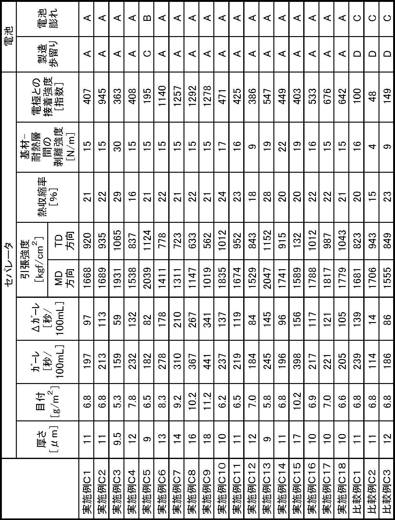
耐熱性多孔質層を形成後にその表面を走査型電子顕微鏡で観察した。実施例C1~C18及び比較例C1においては、多孔性被膜が形成されていた。実施例C1~C12、C14~C18及び比較例C1においては、無機粒子が多孔性被膜によって結着され且つ覆われていた。比較例C2~C3においては、フィブリル状の樹脂により無機粒子が結着されていたが、多孔性被膜は形成されていなかった。
<第二のセパレータの作製>
[実施例D1]
メタ型アラミド(ポリメタフェニレンイソフタルアミド、帝人、コーネックス)と、水酸化マグネシウム(協和化学社、キスマ5P、体積平均粒径0.8μm、BET比表面積6.8m2/g)とを、両者の質量比が20:80で、メタ型アラミド濃度が4質量%となるように、ジメチルアセトアミド(DMAc)とトリプロピレングリコール(TPG)の混合溶媒(DMAc:TPG=80:20[質量比])に攪拌混合し、塗工液(D1)を得た。
[実施例D1]
メタ型アラミド(ポリメタフェニレンイソフタルアミド、帝人、コーネックス)と、水酸化マグネシウム(協和化学社、キスマ5P、体積平均粒径0.8μm、BET比表面積6.8m2/g)とを、両者の質量比が20:80で、メタ型アラミド濃度が4質量%となるように、ジメチルアセトアミド(DMAc)とトリプロピレングリコール(TPG)の混合溶媒(DMAc:TPG=80:20[質量比])に攪拌混合し、塗工液(D1)を得た。
ポリフッ化ビニリデン樹脂粒子(融点140℃、体積平均粒径0.2μm)が水に分散したPVDF粒子分散液(固形分濃度7質量%)を用意した。
一対のマイヤーバーに塗工液(D1)を適量のせ、ポリエチレン微多孔膜(厚さ6μm、空孔率40%、ガーレ値100秒/100mL)をマイヤーバー間に通して、塗工液(D1)を両面に等量塗工した。これを、凝固液(DMAc:TPG:水=30:8:62[質量比]、液温40℃)に浸漬し塗工層を固化させ、次いで、水温40℃の水洗槽で洗浄し、乾燥した。次いで、これを、PVDF粒子分散液を適量のせた一対のバーコータ間に通して、PVDF粒子分散液を両面に等量塗工し、乾燥した。こうして、ポリエチレン微多孔膜の両面に耐熱性多孔質層及び接着層が形成されたセパレータを得た。
[実施例D2]
PVDF粒子分散液を、アクリル樹脂粒子(ガラス転移温度59℃、体積平均粒径0.5μm)が水に分散したアクリル樹脂粒子分散液(固形分濃度7質量%)に変更した以外は、実施例D1と同様にしてセパレータを作製した。
PVDF粒子分散液を、アクリル樹脂粒子(ガラス転移温度59℃、体積平均粒径0.5μm)が水に分散したアクリル樹脂粒子分散液(固形分濃度7質量%)に変更した以外は、実施例D1と同様にしてセパレータを作製した。
[実施例D3]
メタ型アラミドを、下記のパラ型アラミド(ポリパラフェニレンテレフタルアミド)に変更した以外は、実施例D1と同様にしてセパレータを作製した。
メタ型アラミドを、下記のパラ型アラミド(ポリパラフェニレンテレフタルアミド)に変更した以外は、実施例D1と同様にしてセパレータを作製した。
フラスコに4200gのN-メチル-ピロリドン(NMP)を仕込み、200℃で2時間乾燥した塩化カルシウム272.65gを添加して100℃に昇温した。塩化カルシウムが完全に溶解した後、液温を室温に戻して、パラフェニレンジアミン132.91gを添加し完全に溶解させた。この溶液を20±2℃に保ったまま、テレフタル酸ジクロライド243.32gを10分割して約5分おきに添加した。次いで、溶液を20±2℃に保ったまま1時間熟成し、気泡を抜くため減圧下30分間攪拌した。次いで、この重合液100gにNMP溶液を徐々に添加し、ポリパラフェニレンテレフタルアミド濃度を2質量%とした。
[実施例D4]
メタ型アラミドを、ポリエーテルイミド(SABIC社、ウルテム)に変更した以外は、実施例D1と同様にしてセパレータを作製した。
メタ型アラミドを、ポリエーテルイミド(SABIC社、ウルテム)に変更した以外は、実施例D1と同様にしてセパレータを作製した。
[実施例D5~D11]
耐熱性多孔質層又は接着層の塗工量を表7に記載のとおりに変更した以外は、実施例D1と同様にしてセパレータを作製した。
耐熱性多孔質層又は接着層の塗工量を表7に記載のとおりに変更した以外は、実施例D1と同様にしてセパレータを作製した。
[実施例D12~D15]
水酸化マグネシウムの含有量を表7に記載のとおりに変更した以外は、実施例D1と同様にしてセパレータを作製した。
水酸化マグネシウムの含有量を表7に記載のとおりに変更した以外は、実施例D1と同様にしてセパレータを作製した。
[実施例D16]
塗工液(D1)を、下記の塗工液(D16)に変更し、凝固液の温度を20℃に変更し、水洗槽の水温を20℃に変更した以外は、実施例D1と同様にしてセパレータを作製した。
塗工液(D1)を、下記の塗工液(D16)に変更し、凝固液の温度を20℃に変更し、水洗槽の水温を20℃に変更した以外は、実施例D1と同様にしてセパレータを作製した。
メタ型アラミド(実施例D1において使用したものと同じ)と、水酸化マグネシウム(実施例D1において使用したものと同じ)とを、両者の質量比が20:80で、メタ型アラミド濃度が5質量%となるように、DMAcとTPGの混合溶媒(DMAc:TPG=90:10[質量比])に攪拌混合し、塗工液(D16)を得た。
[実施例D17]
アルミナ粒子(住友化学社、AKP-3000、体積平均粒径0.45μm、テトラポッド状粒子)と、粘度調整剤であるカルボキシメチルセルロース(ダイセルファインケム社、D1200、エーテル化度0.8~1.0)と、結着樹脂としてアクリル樹脂(DIC社、DICNAL LSE-16AD4)と、非イオン性界面活性剤(サンノプコ社、SNウェット366)とを質量比85:3.8:11:0.2にて混合し、水を添加して分散させ、固形分濃度40質量%の塗工液(D17)を作製した。
アルミナ粒子(住友化学社、AKP-3000、体積平均粒径0.45μm、テトラポッド状粒子)と、粘度調整剤であるカルボキシメチルセルロース(ダイセルファインケム社、D1200、エーテル化度0.8~1.0)と、結着樹脂としてアクリル樹脂(DIC社、DICNAL LSE-16AD4)と、非イオン性界面活性剤(サンノプコ社、SNウェット366)とを質量比85:3.8:11:0.2にて混合し、水を添加して分散させ、固形分濃度40質量%の塗工液(D17)を作製した。
一対のマイヤーバーに塗工液(D17)を適量のせ、ポリエチレン微多孔膜(実施例D1において使用したものと同じ)をマイヤーバー間に通して、塗工液(D17)を両面に等量塗工し、乾燥した。次いで、これを、PVDF粒子分散液(実施例D1において使用したものと同じ)を適量のせた一対のバーコータ間に通して、PVDF粒子分散液を両面に等量塗工し、乾燥した。こうして、ポリエチレン微多孔膜の両面に耐熱性多孔質層及び接着層が形成されたセパレータを得た。
[実施例D18]
ポリエチレン微多孔膜を、多層構造の微多孔膜(ポリプロピレン層/ポリエチレン層/ポリプロピレン層、厚さ12μm、空孔率44%、ガーレ値242秒/100mL)に変更した以外は、実施例D1と同様にしてセパレータを作製した。
ポリエチレン微多孔膜を、多層構造の微多孔膜(ポリプロピレン層/ポリエチレン層/ポリプロピレン層、厚さ12μm、空孔率44%、ガーレ値242秒/100mL)に変更した以外は、実施例D1と同様にしてセパレータを作製した。
[実施例D19]
PVDF粒子分散液を、ポリフッ化ビニリデン樹脂粒子(融点140℃、体積平均粒径0.2μm)とアクリル樹脂粒子(ガラス転移温度59℃、体積平均粒径0.5μm)とが質量比90:10にて水に分散した水性分散液(固形分濃度7質量%)に変更した以外は、実施例D1と同様にしてセパレータを作製した。
PVDF粒子分散液を、ポリフッ化ビニリデン樹脂粒子(融点140℃、体積平均粒径0.2μm)とアクリル樹脂粒子(ガラス転移温度59℃、体積平均粒径0.5μm)とが質量比90:10にて水に分散した水性分散液(固形分濃度7質量%)に変更した以外は、実施例D1と同様にしてセパレータを作製した。
[実施例D20]
PVDF粒子分散液を、ポリフッ化ビニリデン樹脂粒子(融点140℃、体積平均粒径0.2μm)とアクリル樹脂粒子(ガラス転移温度59℃、体積平均粒径0.5μm)とが質量比70:30にて水に分散した水性分散液(固形分濃度7質量%)に変更した以外は、実施例D1と同様にしてセパレータを作製した。
PVDF粒子分散液を、ポリフッ化ビニリデン樹脂粒子(融点140℃、体積平均粒径0.2μm)とアクリル樹脂粒子(ガラス転移温度59℃、体積平均粒径0.5μm)とが質量比70:30にて水に分散した水性分散液(固形分濃度7質量%)に変更した以外は、実施例D1と同様にしてセパレータを作製した。
[実施例D21]
PVDF粒子分散液を、ポリフッ化ビニリデン樹脂粒子(融点140℃、体積平均粒径0.2μm)とアクリル樹脂粒子(ガラス転移温度59℃、体積平均粒径0.5μm)とが質量比50:50にて水に分散した水性分散液(固形分濃度7質量%)に変更した以外は、実施例D1と同様にしてセパレータを作製した。
PVDF粒子分散液を、ポリフッ化ビニリデン樹脂粒子(融点140℃、体積平均粒径0.2μm)とアクリル樹脂粒子(ガラス転移温度59℃、体積平均粒径0.5μm)とが質量比50:50にて水に分散した水性分散液(固形分濃度7質量%)に変更した以外は、実施例D1と同様にしてセパレータを作製した。
[比較例D1]
ポリフッ化ビニリデン系樹脂(フッ化ビニリデン-ヘキサフルオロプロピレン共重合体、重量平均分子量113万、ヘキサフルオロプロピレン含有量5.4質量%)を、ポリフッ化ビニリデン系樹脂濃度が5質量%となるように、DMAc:TPG=90:10[質量比]の混合溶媒に攪拌混合し、接着層形成用塗工液を得た。
ポリフッ化ビニリデン系樹脂(フッ化ビニリデン-ヘキサフルオロプロピレン共重合体、重量平均分子量113万、ヘキサフルオロプロピレン含有量5.4質量%)を、ポリフッ化ビニリデン系樹脂濃度が5質量%となるように、DMAc:TPG=90:10[質量比]の混合溶媒に攪拌混合し、接着層形成用塗工液を得た。
実施例D1と同様にして、塗工液(D1)をポリエチレン微多孔膜(実施例D1において使用したものと同じ)の両面に等量塗工し、凝固液に浸漬し塗工層を固化させ、洗浄及び乾燥した。次いで、これを、接着層形成用塗工液を適量のせた一対のバーコータ間に通して、接着層形成用塗工液を両面に等量塗工し、凝固液(DMAc:TPG:水=30:8:62[質量比]、液温40℃)に浸漬し塗工層を固化させ、次いで、水温40℃の水洗槽で洗浄し、乾燥した。こうして、ポリエチレン微多孔膜の両面に耐熱性多孔質層及び接着層が形成されたセパレータを得た。
[比較例D2]
メタ型アラミドを、実施例D4で使用したポリエーテルイミドに変更した以外は、比較例D1と同様にしてセパレータを作製した。
メタ型アラミドを、実施例D4で使用したポリエーテルイミドに変更した以外は、比較例D1と同様にしてセパレータを作製した。
[比較例D3]
実施例D17で作製した塗工液(D17)と、比較例D1で作製した接着層形成用塗工液を用意した。
実施例D17で作製した塗工液(D17)と、比較例D1で作製した接着層形成用塗工液を用意した。
一対のマイヤーバーに塗工液(D17)を適量のせ、ポリエチレン微多孔膜(実施例D1において使用したものと同じ)をマイヤーバー間に通して、塗工液(D17)を両面に等量塗工し、乾燥した。次いで、これを、接着層形成用塗工液を適量のせた一対のバーコータ間に通して、接着層形成用塗工液を両面に等量塗工し、凝固液(DMAc:TPG:水=30:8:62[質量比]、液温40℃)に浸漬し塗工層を固化させ、次いで、水温40℃の水洗槽で洗浄し、乾燥した。こうして、ポリエチレン微多孔膜の両面に耐熱性多孔質層及び接着層が形成されたセパレータを得た。
[比較例D4]
アルミナ粒子(住友化学社、AKP-3000、体積平均粒径0.45μm、テトラポッド状粒子)と、粘度調整剤であるカルボキシメチルセルロース(ダイセルファインケム社、D1200、エーテル化度0.8~1.0)と、結着樹脂としてアクリル樹脂(DIC社、DICNAL LSE-16AD4)と、非イオン性界面活性剤(サンノプコ社、SNウェット366)とを質量比94.6:3.8:1.4:0.2にて混合し、水を添加して分散させ、固形分濃度40質量%の塗工液(DC4)を作製した。
アルミナ粒子(住友化学社、AKP-3000、体積平均粒径0.45μm、テトラポッド状粒子)と、粘度調整剤であるカルボキシメチルセルロース(ダイセルファインケム社、D1200、エーテル化度0.8~1.0)と、結着樹脂としてアクリル樹脂(DIC社、DICNAL LSE-16AD4)と、非イオン性界面活性剤(サンノプコ社、SNウェット366)とを質量比94.6:3.8:1.4:0.2にて混合し、水を添加して分散させ、固形分濃度40質量%の塗工液(DC4)を作製した。
一対のマイヤーバーに塗工液(DC4)を適量のせ、ポリエチレン微多孔膜(実施例D1において使用したものと同じ)をマイヤーバー間に通して、塗工液(DC4)を両面に等量塗工し、乾燥した。次いで、これを、PVDF粒子分散液(実施例D1において使用したものと同じ)を適量のせた一対のバーコータ間に通して、PVDF粒子分散液を両面に等量塗工し、乾燥した。こうして、ポリエチレン微多孔膜の両面に耐熱性多孔質層及び接着層が形成されたセパレータを得た。
実施例D1~D21及び比較例D1~D4の各セパレータの構成、物性及び評価結果を表7~表8に示す。表7中、PEはポリエチレン、PPはポリプロピレン、アラミドは全芳香族ポリアミド、PVDFはポリフッ化ビニリデン、PVDF-HFPはフッ化ビニリデン-ヘキサフルオロプロピレン共重合体をそれぞれ意味する。


耐熱性多孔質層を形成後にその表面を走査型電子顕微鏡で観察した。実施例D1~D16、D18~D21及び比較例D1~D2においては、多孔性被膜が形成されていた。実施例D1~D14、D16、D18~D21及び比較例D1~D2においては、無機粒子が多孔性被膜によって結着され且つ覆われていた。実施例D17及び比較例D3~D4においては、フィブリル状の樹脂により無機粒子が結着されていたが、多孔性被膜は形成されていなかった。
2017年12月27日に出願された日本国出願番号第2017-252241号の開示は、その全体が参照により本明細書に取り込まれる。
2017年12月27日に出願された日本国出願番号第2017-252242号の開示は、その全体が参照により本明細書に取り込まれる。
2017年12月27日に出願された日本国出願番号第2017-252243号の開示は、その全体が参照により本明細書に取り込まれる。
2017年12月27日に出願された日本国出願番号第2017-252244号の開示は、その全体が参照により本明細書に取り込まれる。
2017年12月27日に出願された日本国出願番号第2017-252242号の開示は、その全体が参照により本明細書に取り込まれる。
2017年12月27日に出願された日本国出願番号第2017-252243号の開示は、その全体が参照により本明細書に取り込まれる。
2017年12月27日に出願された日本国出願番号第2017-252244号の開示は、その全体が参照により本明細書に取り込まれる。
本明細書に記載された全ての文献、特許出願、及び技術規格は、個々の文献、特許出願、及び技術規格が参照により取り込まれることが具体的かつ個々に記された場合と同程度に、本明細書中に参照により取り込まれる。
10A、10B、10C、10D セパレータ
20 多孔質基材
30 耐熱性多孔質層
40 積層体
50 接着層
52 接着性樹脂粒子
20 多孔質基材
30 耐熱性多孔質層
40 積層体
50 接着層
52 接着性樹脂粒子
Claims (10)
- 多孔質基材と、
前記多孔質基材の片面又は両面に設けられ、全芳香族ポリアミド、ポリアミドイミド及びポリイミドからなる群から選ばれる少なくとも1種を含有する多孔性被膜を有する耐熱性多孔質層と、
前記多孔質基材と前記耐熱性多孔質層との積層体の片面又は両面に設けられ、接着性樹脂粒子が前記積層体に付着してなる接着層と、
を備えた非水系二次電池用セパレータ。 - 前記多孔質基材と前記耐熱性多孔質層との間の剥離強度が5N/m~75N/mである、請求項1に記載の非水系二次電池用セパレータ。
- 前記耐熱性多孔質層がさらに無機粒子を含有し、前記耐熱性多孔質層に占める前記無機粒子の質量割合が50質量%~90質量%である、請求項1又は請求項2に記載の非水系二次電池用セパレータ。
- 多孔質基材と、
前記多孔質基材の片面又は両面に設けられ、分子中にアミド結合及びイミド結合の少なくとも一方を有する耐熱性樹脂及び無機粒子の少なくとも一方を含有する耐熱性多孔質層と、
前記多孔質基材と前記耐熱性多孔質層との積層体の片面又は両面に設けられ、接着性樹脂粒子が前記積層体に付着してなる接着層と、を備え、
前記多孔質基材と前記耐熱性多孔質層との間の剥離強度が5N/m~75N/mである、非水系二次電池用セパレータ。 - 前記接着性樹脂粒子が、ポリフッ化ビニリデン系樹脂を含む第一の接着性樹脂粒子とアクリル系樹脂を含む第二の接着性樹脂粒子との混合物を含む、請求項1~請求項4のいずれか1項に記載の非水系二次電池用セパレータ。
- 前記非水系二次電池用セパレータのガーレ値と前記多孔質基材のガーレ値との差が20秒/100mL~300秒/100mLである、請求項1~請求項5のいずれか1項に記載の非水系二次電池用セパレータ。
- 前記非水系二次電池用セパレータのMD方向の引張強度及びTD方向の引張強度の少なくとも一方が500kgf/cm2~3000kgf/cm2である、請求項1~請求項6のいずれか1項に記載の非水系二次電池用セパレータ。
- 前記接着層の重量が前記積層体の片面あたり0.2g/m2~2.0g/m2である、請求項1~請求項7のいずれか1項に記載の非水系二次電池用セパレータ。
- 前記多孔質基材がポリプロピレンを含有する微多孔膜である、請求項1~請求項8のいずれか1項に記載の非水系二次電池用セパレータ。
- 正極と、負極と、前記正極及び前記負極の間に配置された請求項1~請求項9のいずれか1項に記載の非水系二次電池用セパレータと、を備え、リチウムのドープ・脱ドープにより起電力を得る非水系二次電池。
Priority Applications (5)
| Application Number | Priority Date | Filing Date | Title |
|---|---|---|---|
| CN201880081226.5A CN111492504B (zh) | 2017-12-27 | 2018-11-30 | 非水系二次电池用隔膜及非水系二次电池 |
| EP18896369.8A EP3734698A4 (en) | 2017-12-27 | 2018-11-30 | ISOLATOR FOR SECONDARY BATTERIES WITH WATER-FREE ELECTROLYTE AND SECONDARY BATTERY WITH WATER-FREE ELECTROLYTE |
| US16/958,533 US12074339B2 (en) | 2017-12-27 | 2018-11-30 | Separator including porous substrate, heat resistant porous layer, and adhesive layer, and non-aqueous secondary battery including the same |
| JP2019507959A JP6513893B1 (ja) | 2017-12-27 | 2018-11-30 | 非水系二次電池用セパレータ及び非水系二次電池 |
| KR1020207017458A KR20200102437A (ko) | 2017-12-27 | 2018-11-30 | 비수계 이차 전지용 세퍼레이터 및 비수계 이차 전지 |
Applications Claiming Priority (8)
| Application Number | Priority Date | Filing Date | Title |
|---|---|---|---|
| JP2017252244 | 2017-12-27 | ||
| JP2017-252244 | 2017-12-27 | ||
| JP2017-252241 | 2017-12-27 | ||
| JP2017252242 | 2017-12-27 | ||
| JP2017-252243 | 2017-12-27 | ||
| JP2017252241 | 2017-12-27 | ||
| JP2017252243 | 2017-12-27 | ||
| JP2017-252242 | 2017-12-27 |
Publications (1)
| Publication Number | Publication Date |
|---|---|
| WO2019130994A1 true WO2019130994A1 (ja) | 2019-07-04 |
Family
ID=67067096
Family Applications (1)
| Application Number | Title | Priority Date | Filing Date |
|---|---|---|---|
| PCT/JP2018/044319 WO2019130994A1 (ja) | 2017-12-27 | 2018-11-30 | 非水系二次電池用セパレータ及び非水系二次電池 |
Country Status (5)
| Country | Link |
|---|---|
| US (1) | US12074339B2 (ja) |
| EP (1) | EP3734698A4 (ja) |
| KR (1) | KR20200102437A (ja) |
| CN (1) | CN111492504B (ja) |
| WO (1) | WO2019130994A1 (ja) |
Cited By (11)
| Publication number | Priority date | Publication date | Assignee | Title |
|---|---|---|---|---|
| KR20210019305A (ko) * | 2019-08-12 | 2021-02-22 | 삼성에스디아이 주식회사 | 이차전지용 분리막, 그 제조방법 및 이를 포함하는 이차전지 |
| WO2021049403A1 (ja) * | 2019-09-10 | 2021-03-18 | 東レ株式会社 | 角缶型非水電解質二次電池用セパレータ、電極積層体、及び角缶型非水電解質二次電池 |
| WO2021172195A1 (ja) * | 2020-02-28 | 2021-09-02 | 帝人株式会社 | 非水系二次電池用セパレータ及び非水系二次電池 |
| WO2021230037A1 (ja) * | 2020-05-13 | 2021-11-18 | 株式会社ダイセル | 二次電池用セパレータ |
| US20220029243A1 (en) * | 2018-12-26 | 2022-01-27 | Panasonic Intellectual Property Management Co., Ltd. | Non-aqueous electrolyte secondary battery |
| WO2022035298A1 (ko) * | 2020-08-14 | 2022-02-17 | 주식회사 엘지에너지솔루션 | 세퍼레이터 및 이를 포함하는 전기화학소자 |
| JPWO2022054279A1 (ja) * | 2020-09-14 | 2022-03-17 | ||
| WO2023037989A1 (ja) | 2021-09-10 | 2023-03-16 | 帝人株式会社 | 非水系二次電池用セパレータ及び非水系二次電池 |
| WO2023037990A1 (ja) | 2021-09-10 | 2023-03-16 | 帝人株式会社 | 非水系二次電池用セパレータ及び非水系二次電池 |
| WO2023190521A1 (ja) * | 2022-03-31 | 2023-10-05 | 帝人株式会社 | 非水系二次電池用セパレータ及び非水系二次電池 |
| WO2023210786A1 (ja) * | 2022-04-28 | 2023-11-02 | 帝人株式会社 | 非水系二次電池用セパレータ及び非水系二次電池 |
Families Citing this family (8)
| Publication number | Priority date | Publication date | Assignee | Title |
|---|---|---|---|---|
| KR102592147B1 (ko) * | 2018-04-20 | 2023-10-23 | 삼성전자주식회사 | 복합분리막, 그 제조방법 및 이를 포함하는 리튬이차전지 |
| CN114361710A (zh) * | 2020-09-29 | 2022-04-15 | 宁德新能源科技有限公司 | 一种隔离膜、包含该隔离膜的电化学装置及电子装置 |
| JP2022148612A (ja) * | 2021-03-24 | 2022-10-06 | 富士フイルムビジネスイノベーション株式会社 | ポリイミド多孔質膜、非水系二次電池用セパレータ、二次電池、及び二次電池の製造方法 |
| CN114006024B (zh) * | 2021-10-25 | 2024-07-16 | 珠海冠宇电池股份有限公司 | 一种隔膜及含有该隔膜的电池 |
| CN114267923A (zh) * | 2021-12-23 | 2022-04-01 | 中材锂膜有限公司 | 一种电池隔离膜及其制备方法、二次电池 |
| CN114335904B (zh) * | 2022-02-28 | 2022-07-12 | 湖南中锂新材料科技有限公司 | 一种锂电池复合隔膜及其制备方法和应用 |
| KR20230169789A (ko) * | 2022-06-09 | 2023-12-18 | 에스케이이노베이션 주식회사 | 분리막, 이의 제조방법 및 상기 분리막을 포함하는 전기화학소자 |
| CN117410651A (zh) * | 2022-07-06 | 2024-01-16 | 华为技术有限公司 | 复合隔膜及其制备方法、二次电池和用电设备 |
Citations (9)
| Publication number | Priority date | Publication date | Assignee | Title |
|---|---|---|---|---|
| JPS5946257B2 (ja) | 1976-11-01 | 1984-11-12 | 帝人株式会社 | ポリエステルの製造法 |
| JPS6112115B2 (ja) | 1980-06-11 | 1986-04-07 | Oki Denki Kogyo Kk | |
| JP2010092718A (ja) * | 2008-10-08 | 2010-04-22 | Teijin Ltd | 非水系二次電池用セパレータ及び非水系二次電池 |
| JP2013020769A (ja) | 2011-07-08 | 2013-01-31 | Teijin Ltd | 非水電解質電池用セパレータ及び非水電解質電池 |
| JP2013196839A (ja) * | 2012-03-16 | 2013-09-30 | Tdk Corp | 非水系二次電池用セパレータ |
| WO2013151144A1 (ja) | 2012-04-05 | 2013-10-10 | 日本ゼオン株式会社 | 二次電池用セパレータ |
| JP5971662B2 (ja) | 2012-09-24 | 2016-08-17 | エルジー・ケム・リミテッド | リチウム二次電池用セパレータの製造方法、その方法で製造されたセパレータ、及びそれを含むリチウム二次電池 |
| JP5976015B2 (ja) | 2011-02-15 | 2016-08-23 | エルジー・ケム・リミテッド | セパレータ、その製造方法、及びそれを備える電気化学素子 |
| JP2016207616A (ja) * | 2015-04-28 | 2016-12-08 | 日立マクセル株式会社 | 電気化学素子用セパレータ、および電気化学素子の製造方法 |
Family Cites Families (27)
| Publication number | Priority date | Publication date | Assignee | Title |
|---|---|---|---|---|
| JP2001006744A (ja) | 1999-06-16 | 2001-01-12 | Furukawa Electric Co Ltd:The | 有機電解液を用いた電池 |
| WO2010021248A1 (ja) * | 2008-08-19 | 2010-02-25 | 帝人株式会社 | 非水系二次電池用セパレータ |
| JP2010146839A (ja) | 2008-12-18 | 2010-07-01 | Teijin Ltd | 非水系二次電池用セパレータ及び非水系二次電池 |
| JP5400508B2 (ja) * | 2009-07-14 | 2014-01-29 | 帝人株式会社 | 非水系二次電池用セパレータ |
| JP5509816B2 (ja) * | 2009-11-30 | 2014-06-04 | ソニー株式会社 | セパレータ、これを用いた電池および微多孔膜 |
| JP2011192529A (ja) * | 2010-03-15 | 2011-09-29 | Teijin Ltd | ポリオレフィン微多孔膜、非水系二次電池用セパレータ及び非水系二次電池 |
| JP2011204587A (ja) | 2010-03-26 | 2011-10-13 | Teijin Ltd | 非水系二次電池用セパレータ、非水系二次電池、および非水系二次電池用セパレータの製造方法 |
| WO2011161837A1 (ja) * | 2010-06-25 | 2011-12-29 | 東レ株式会社 | 複合多孔質膜、複合多孔質膜の製造方法並びにそれを用いた電池用セパレーター |
| JP5089831B2 (ja) | 2010-10-29 | 2012-12-05 | 帝人株式会社 | 非水電解質電池用セパレータ及び非水電解質二次電池 |
| JP2012099324A (ja) * | 2010-11-01 | 2012-05-24 | Teijin Ltd | 非水電解質二次電池用セパレータ及び非水電解質二次電池 |
| JP5834322B2 (ja) * | 2011-07-20 | 2015-12-16 | エルジー・ケム・リミテッド | セパレータ、その製造方法及びこれを備えた電気化学素子 |
| CN103828115B (zh) | 2011-09-26 | 2016-10-26 | 住友化学株式会社 | 二次电池用粘合树脂组合物 |
| JP5946257B2 (ja) | 2011-09-29 | 2016-07-06 | デクセリアルズ株式会社 | 電池用セパレータシート、その製造方法及び電池 |
| CN202333016U (zh) * | 2011-11-25 | 2012-07-11 | 佛山市金辉高科光电材料有限公司 | 一种含有耐热树脂涂层的多孔多层电池复合膜 |
| KR102066490B1 (ko) | 2012-09-28 | 2020-01-15 | 제온 코포레이션 | 2 차 전지용 다공막 세퍼레이터 및 그 제조 방법, 그리고 2 차 전지 |
| US10074840B2 (en) | 2012-11-30 | 2018-09-11 | Teijin Limited | Separator for non-aqueous secondary battery and non-aqueous secondary battery |
| JP6186783B2 (ja) * | 2013-03-19 | 2017-08-30 | ソニー株式会社 | セパレータ、電池、電池パック、電子機器、電動車両、蓄電装置および電力システム |
| JP6255768B2 (ja) * | 2013-07-24 | 2018-01-10 | 日産自動車株式会社 | 非水電解質二次電池用セパレータおよびこれを含む非水電解質二次電池 |
| CN106104850B (zh) | 2014-09-26 | 2018-12-25 | 旭化成株式会社 | 蓄电装置用分隔件 |
| US20170338459A1 (en) | 2014-12-15 | 2017-11-23 | Teijin Limited | Separator for a non-aqueous electrolyte battery, non-aqueous electrolyte battery, and method of manufacturing non-aqueous electrolyte battery |
| JP6430839B2 (ja) | 2015-01-26 | 2018-11-28 | 旭化成株式会社 | 電池用セパレータ、及び非水電解液電池 |
| KR20170019522A (ko) * | 2015-08-11 | 2017-02-22 | 더블유스코프코리아 주식회사 | 다공성 다층 분리막 및 그 제조방법 |
| WO2017047576A1 (ja) * | 2015-09-16 | 2017-03-23 | 日立マクセル株式会社 | 電気化学素子用セパレータ、その製造方法および電気化学素子の製造方法 |
| KR20170045438A (ko) | 2015-10-16 | 2017-04-27 | 더블유스코프코리아 주식회사 | 이차전지용 전극 접착성 코팅 분리막 및 그 제조 방법 |
| CN108352482B (zh) * | 2015-11-11 | 2021-09-10 | 株式会社Lg化学 | 具有电极粘合剂层的隔离件和包括其的电化学装置 |
| CN105552284B (zh) * | 2015-12-22 | 2018-11-06 | 沧州明珠隔膜科技有限公司 | 一种复合涂层锂离子电池隔膜及其制备方法 |
| JP2017132925A (ja) | 2016-01-28 | 2017-08-03 | 積水化学工業株式会社 | 耐熱性合成樹脂微多孔フィルム |
-
2018
- 2018-11-30 EP EP18896369.8A patent/EP3734698A4/en active Pending
- 2018-11-30 US US16/958,533 patent/US12074339B2/en active Active
- 2018-11-30 CN CN201880081226.5A patent/CN111492504B/zh active Active
- 2018-11-30 KR KR1020207017458A patent/KR20200102437A/ko not_active Application Discontinuation
- 2018-11-30 WO PCT/JP2018/044319 patent/WO2019130994A1/ja unknown
Patent Citations (9)
| Publication number | Priority date | Publication date | Assignee | Title |
|---|---|---|---|---|
| JPS5946257B2 (ja) | 1976-11-01 | 1984-11-12 | 帝人株式会社 | ポリエステルの製造法 |
| JPS6112115B2 (ja) | 1980-06-11 | 1986-04-07 | Oki Denki Kogyo Kk | |
| JP2010092718A (ja) * | 2008-10-08 | 2010-04-22 | Teijin Ltd | 非水系二次電池用セパレータ及び非水系二次電池 |
| JP5976015B2 (ja) | 2011-02-15 | 2016-08-23 | エルジー・ケム・リミテッド | セパレータ、その製造方法、及びそれを備える電気化学素子 |
| JP2013020769A (ja) | 2011-07-08 | 2013-01-31 | Teijin Ltd | 非水電解質電池用セパレータ及び非水電解質電池 |
| JP2013196839A (ja) * | 2012-03-16 | 2013-09-30 | Tdk Corp | 非水系二次電池用セパレータ |
| WO2013151144A1 (ja) | 2012-04-05 | 2013-10-10 | 日本ゼオン株式会社 | 二次電池用セパレータ |
| JP5971662B2 (ja) | 2012-09-24 | 2016-08-17 | エルジー・ケム・リミテッド | リチウム二次電池用セパレータの製造方法、その方法で製造されたセパレータ、及びそれを含むリチウム二次電池 |
| JP2016207616A (ja) * | 2015-04-28 | 2016-12-08 | 日立マクセル株式会社 | 電気化学素子用セパレータ、および電気化学素子の製造方法 |
Non-Patent Citations (1)
| Title |
|---|
| See also references of EP3734698A4 |
Cited By (18)
| Publication number | Priority date | Publication date | Assignee | Title |
|---|---|---|---|---|
| US20220029243A1 (en) * | 2018-12-26 | 2022-01-27 | Panasonic Intellectual Property Management Co., Ltd. | Non-aqueous electrolyte secondary battery |
| KR102472908B1 (ko) * | 2019-08-12 | 2022-12-01 | 삼성에스디아이 주식회사 | 이차전지용 분리막, 그 제조방법 및 이를 포함하는 이차전지 |
| KR20210019305A (ko) * | 2019-08-12 | 2021-02-22 | 삼성에스디아이 주식회사 | 이차전지용 분리막, 그 제조방법 및 이를 포함하는 이차전지 |
| WO2021049403A1 (ja) * | 2019-09-10 | 2021-03-18 | 東レ株式会社 | 角缶型非水電解質二次電池用セパレータ、電極積層体、及び角缶型非水電解質二次電池 |
| WO2021172195A1 (ja) * | 2020-02-28 | 2021-09-02 | 帝人株式会社 | 非水系二次電池用セパレータ及び非水系二次電池 |
| JP2021136221A (ja) * | 2020-02-28 | 2021-09-13 | 帝人株式会社 | 非水系二次電池用セパレータ及び非水系二次電池 |
| JP7545216B2 (ja) | 2020-02-28 | 2024-09-04 | 帝人株式会社 | 非水系二次電池用セパレータ及び非水系二次電池 |
| WO2021230037A1 (ja) * | 2020-05-13 | 2021-11-18 | 株式会社ダイセル | 二次電池用セパレータ |
| JP2023524704A (ja) * | 2020-08-14 | 2023-06-13 | エルジー エナジー ソリューション リミテッド | セパレーター及びこれを含む電気化学素子 |
| JP7408224B2 (ja) | 2020-08-14 | 2024-01-05 | エルジー エナジー ソリューション リミテッド | セパレーター及びこれを含む電気化学素子 |
| WO2022035298A1 (ko) * | 2020-08-14 | 2022-02-17 | 주식회사 엘지에너지솔루션 | 세퍼레이터 및 이를 포함하는 전기화학소자 |
| JPWO2022054279A1 (ja) * | 2020-09-14 | 2022-03-17 | ||
| WO2023037989A1 (ja) | 2021-09-10 | 2023-03-16 | 帝人株式会社 | 非水系二次電池用セパレータ及び非水系二次電池 |
| WO2023037990A1 (ja) | 2021-09-10 | 2023-03-16 | 帝人株式会社 | 非水系二次電池用セパレータ及び非水系二次電池 |
| WO2023190521A1 (ja) * | 2022-03-31 | 2023-10-05 | 帝人株式会社 | 非水系二次電池用セパレータ及び非水系二次電池 |
| WO2023210786A1 (ja) * | 2022-04-28 | 2023-11-02 | 帝人株式会社 | 非水系二次電池用セパレータ及び非水系二次電池 |
| JP2023164114A (ja) * | 2022-04-28 | 2023-11-10 | 帝人株式会社 | 非水系二次電池用セパレータ及び非水系二次電池 |
| JP7482935B2 (ja) | 2022-04-28 | 2024-05-14 | 帝人株式会社 | 非水系二次電池用セパレータ及び非水系二次電池 |
Also Published As
| Publication number | Publication date |
|---|---|
| EP3734698A1 (en) | 2020-11-04 |
| US20210057703A1 (en) | 2021-02-25 |
| EP3734698A4 (en) | 2021-10-13 |
| CN111492504B (zh) | 2024-04-30 |
| CN111492504A (zh) | 2020-08-04 |
| US12074339B2 (en) | 2024-08-27 |
| KR20200102437A (ko) | 2020-08-31 |
Similar Documents
| Publication | Publication Date | Title |
|---|---|---|
| WO2019130994A1 (ja) | 非水系二次電池用セパレータ及び非水系二次電池 | |
| JP6986640B2 (ja) | 非水系二次電池用セパレータ及び非水系二次電池 | |
| JP6054001B2 (ja) | 非水電解質電池用セパレータ、非水電解質電池、および、非水電解質電池の製造方法 | |
| JP5624251B2 (ja) | 非水電解質電池用セパレータ及び非水電解質電池 | |
| JP6513893B1 (ja) | 非水系二次電池用セパレータ及び非水系二次電池 | |
| JP5603522B2 (ja) | 非水電解質電池用セパレータおよび非水電解質電池 | |
| JP6078703B1 (ja) | 非水系二次電池用セパレータ、非水系二次電池及び非水系二次電池の製造方法 | |
| JP6526359B1 (ja) | 非水系二次電池用セパレータ及び非水系二次電池 | |
| WO2019146155A1 (ja) | 非水系二次電池用セパレータ及び非水系二次電池 | |
| JP6984033B2 (ja) | 非水系二次電池用セパレータ及び非水系二次電池 | |
| JP2022026936A (ja) | 非水系二次電池用セパレータ及び非水系二次電池 | |
| JP2016181439A (ja) | 非水系二次電池用セパレータ及び非水系二次電池 | |
| US20230275320A1 (en) | Separator for non-aqueous secondary battery and non-aqueous secondary battery | |
| JP7483154B2 (ja) | 非水系二次電池用セパレータ及び非水系二次電池 | |
| JP7482935B2 (ja) | 非水系二次電池用セパレータ及び非水系二次電池 | |
| JP2014026947A (ja) | 非水電解質電池用セパレータ及び非水電解質電池 | |
| JP2021190269A (ja) | 非水系二次電池用セパレータ及び非水系二次電池 | |
| JP2021190268A (ja) | 非水系二次電池用セパレータ及び非水系二次電池 |
Legal Events
| Date | Code | Title | Description |
|---|---|---|---|
| ENP | Entry into the national phase |
Ref document number: 2019507959 Country of ref document: JP Kind code of ref document: A |
|
| 121 | Ep: the epo has been informed by wipo that ep was designated in this application |
Ref document number: 18896369 Country of ref document: EP Kind code of ref document: A1 |
|
| NENP | Non-entry into the national phase |
Ref country code: DE |
|
| ENP | Entry into the national phase |
Ref document number: 2018896369 Country of ref document: EP Effective date: 20200727 |