WO2018221694A1 - 水素化脱硫用触媒構造体、該触媒構造体を備える水素化脱硫装置及び水素化脱硫用触媒構造体の製造方法 - Google Patents
水素化脱硫用触媒構造体、該触媒構造体を備える水素化脱硫装置及び水素化脱硫用触媒構造体の製造方法 Download PDFInfo
- Publication number
- WO2018221694A1 WO2018221694A1 PCT/JP2018/021082 JP2018021082W WO2018221694A1 WO 2018221694 A1 WO2018221694 A1 WO 2018221694A1 JP 2018021082 W JP2018021082 W JP 2018021082W WO 2018221694 A1 WO2018221694 A1 WO 2018221694A1
- Authority
- WO
- WIPO (PCT)
- Prior art keywords
- catalyst structure
- hydrodesulfurization
- catalyst
- metal
- precursor material
- Prior art date
Links
- 239000003054 catalyst Substances 0.000 title claims abstract description 295
- 238000004519 manufacturing process Methods 0.000 title claims description 20
- 239000000463 material Substances 0.000 claims abstract description 162
- 230000003197 catalytic effect Effects 0.000 claims abstract description 51
- -1 zeolite compound Chemical class 0.000 claims abstract description 16
- 229910052751 metal Inorganic materials 0.000 claims description 116
- 239000002184 metal Substances 0.000 claims description 114
- 239000002243 precursor Substances 0.000 claims description 96
- 239000010419 fine particle Substances 0.000 claims description 91
- 229910044991 metal oxide Inorganic materials 0.000 claims description 90
- 150000004706 metal oxides Chemical group 0.000 claims description 90
- 239000000126 substance Substances 0.000 claims description 67
- 150000001875 compounds Chemical class 0.000 claims description 39
- 239000002245 particle Substances 0.000 claims description 33
- PXHVJJICTQNCMI-UHFFFAOYSA-N Nickel Chemical compound [Ni] PXHVJJICTQNCMI-UHFFFAOYSA-N 0.000 claims description 27
- 238000010335 hydrothermal treatment Methods 0.000 claims description 24
- 239000003795 chemical substances by application Substances 0.000 claims description 20
- 238000010304 firing Methods 0.000 claims description 18
- 229910052759 nickel Inorganic materials 0.000 claims description 13
- ZOKXTWBITQBERF-UHFFFAOYSA-N Molybdenum Chemical compound [Mo] ZOKXTWBITQBERF-UHFFFAOYSA-N 0.000 claims description 11
- 229910052750 molybdenum Inorganic materials 0.000 claims description 11
- 239000011733 molybdenum Substances 0.000 claims description 11
- 229910017052 cobalt Inorganic materials 0.000 claims description 10
- 239000010941 cobalt Substances 0.000 claims description 10
- GUTLYIVDDKVIGB-UHFFFAOYSA-N cobalt atom Chemical compound [Co] GUTLYIVDDKVIGB-UHFFFAOYSA-N 0.000 claims description 10
- WFKWXMTUELFFGS-UHFFFAOYSA-N tungsten Chemical compound [W] WFKWXMTUELFFGS-UHFFFAOYSA-N 0.000 claims description 10
- 229910052721 tungsten Inorganic materials 0.000 claims description 10
- 239000010937 tungsten Substances 0.000 claims description 10
- 239000002736 nonionic surfactant Substances 0.000 claims description 8
- 239000012298 atmosphere Substances 0.000 claims description 7
- 229910052802 copper Inorganic materials 0.000 claims description 7
- 239000010949 copper Chemical group 0.000 claims description 7
- UFHFLCQGNIYNRP-UHFFFAOYSA-N Hydrogen Chemical compound [H][H] UFHFLCQGNIYNRP-UHFFFAOYSA-N 0.000 claims description 6
- RYGMFSIKBFXOCR-UHFFFAOYSA-N Copper Chemical group [Cu] RYGMFSIKBFXOCR-UHFFFAOYSA-N 0.000 claims description 5
- XUIMIQQOPSSXEZ-UHFFFAOYSA-N Silicon Chemical compound [Si] XUIMIQQOPSSXEZ-UHFFFAOYSA-N 0.000 claims description 5
- HCHKCACWOHOZIP-UHFFFAOYSA-N Zinc Chemical group [Zn] HCHKCACWOHOZIP-UHFFFAOYSA-N 0.000 claims description 5
- 229910052710 silicon Inorganic materials 0.000 claims description 5
- 239000010703 silicon Substances 0.000 claims description 5
- 229910052725 zinc Chemical group 0.000 claims description 5
- 239000011701 zinc Chemical group 0.000 claims description 5
- 238000001354 calcination Methods 0.000 claims description 4
- 239000001257 hydrogen Substances 0.000 claims description 2
- 229910052739 hydrogen Inorganic materials 0.000 claims description 2
- 239000008188 pellet Substances 0.000 claims description 2
- 238000011282 treatment Methods 0.000 abstract description 29
- 230000000694 effects Effects 0.000 abstract description 13
- 230000009467 reduction Effects 0.000 abstract description 7
- 239000010457 zeolite Substances 0.000 abstract description 5
- 229910021536 Zeolite Inorganic materials 0.000 abstract description 3
- 239000000243 solution Substances 0.000 description 45
- 239000011148 porous material Substances 0.000 description 31
- OCKPCBLVNKHBMX-UHFFFAOYSA-N butylbenzene Chemical compound CCCCC1=CC=CC=C1 OCKPCBLVNKHBMX-UHFFFAOYSA-N 0.000 description 26
- 238000000034 method Methods 0.000 description 24
- 239000000295 fuel oil Substances 0.000 description 20
- 238000011156 evaluation Methods 0.000 description 19
- 239000012530 fluid Substances 0.000 description 19
- 230000000052 comparative effect Effects 0.000 description 17
- 239000010779 crude oil Substances 0.000 description 17
- VYPSYNLAJGMNEJ-UHFFFAOYSA-N Silicium dioxide Chemical compound O=[Si]=O VYPSYNLAJGMNEJ-UHFFFAOYSA-N 0.000 description 16
- 239000000047 product Substances 0.000 description 16
- 239000004094 surface-active agent Substances 0.000 description 11
- 239000007864 aqueous solution Substances 0.000 description 10
- HNPSIPDUKPIQMN-UHFFFAOYSA-N dioxosilane;oxo(oxoalumanyloxy)alumane Chemical class O=[Si]=O.O=[Al]O[Al]=O HNPSIPDUKPIQMN-UHFFFAOYSA-N 0.000 description 10
- UHOVQNZJYSORNB-UHFFFAOYSA-N Benzene Chemical compound C1=CC=CC=C1 UHOVQNZJYSORNB-UHFFFAOYSA-N 0.000 description 9
- 239000000654 additive Substances 0.000 description 9
- 238000006243 chemical reaction Methods 0.000 description 9
- 238000010438 heat treatment Methods 0.000 description 9
- 239000013335 mesoporous material Substances 0.000 description 9
- 230000000996 additive effect Effects 0.000 description 8
- 238000004220 aggregation Methods 0.000 description 8
- 230000002776 aggregation Effects 0.000 description 8
- 239000011259 mixed solution Substances 0.000 description 8
- DDTIGTPWGISMKL-UHFFFAOYSA-N molybdenum nickel Chemical compound [Ni].[Mo] DDTIGTPWGISMKL-UHFFFAOYSA-N 0.000 description 8
- 239000002244 precipitate Substances 0.000 description 8
- XLYOFNOQVPJJNP-UHFFFAOYSA-N water Substances O XLYOFNOQVPJJNP-UHFFFAOYSA-N 0.000 description 8
- LFQSCWFLJHTTHZ-UHFFFAOYSA-N Ethanol Chemical compound CCO LFQSCWFLJHTTHZ-UHFFFAOYSA-N 0.000 description 7
- 238000006477 desulfuration reaction Methods 0.000 description 7
- 230000023556 desulfurization Effects 0.000 description 7
- 238000001035 drying Methods 0.000 description 7
- 239000007789 gas Substances 0.000 description 7
- 239000003921 oil Substances 0.000 description 7
- 238000000354 decomposition reaction Methods 0.000 description 6
- 239000007788 liquid Substances 0.000 description 6
- 238000005259 measurement Methods 0.000 description 6
- 239000000203 mixture Substances 0.000 description 6
- 150000003839 salts Chemical class 0.000 description 6
- 238000004458 analytical method Methods 0.000 description 5
- 238000004140 cleaning Methods 0.000 description 5
- 238000004821 distillation Methods 0.000 description 5
- 238000009616 inductively coupled plasma Methods 0.000 description 5
- 239000003960 organic solvent Substances 0.000 description 5
- 239000002994 raw material Substances 0.000 description 5
- 238000000235 small-angle X-ray scattering Methods 0.000 description 5
- 239000002904 solvent Substances 0.000 description 5
- 229910003296 Ni-Mo Inorganic materials 0.000 description 4
- 229920003171 Poly (ethylene oxide) Polymers 0.000 description 4
- BOTDANWDWHJENH-UHFFFAOYSA-N Tetraethyl orthosilicate Chemical compound CCO[Si](OCC)(OCC)OCC BOTDANWDWHJENH-UHFFFAOYSA-N 0.000 description 4
- GWEVSGVZZGPLCZ-UHFFFAOYSA-N Titan oxide Chemical compound O=[Ti]=O GWEVSGVZZGPLCZ-UHFFFAOYSA-N 0.000 description 4
- QZYDAIMOJUSSFT-UHFFFAOYSA-N [Co].[Ni].[Mo] Chemical compound [Co].[Ni].[Mo] QZYDAIMOJUSSFT-UHFFFAOYSA-N 0.000 description 4
- WHDPTDWLEKQKKX-UHFFFAOYSA-N cobalt molybdenum Chemical compound [Co].[Co].[Mo] WHDPTDWLEKQKKX-UHFFFAOYSA-N 0.000 description 4
- 238000010586 diagram Methods 0.000 description 4
- 230000004048 modification Effects 0.000 description 4
- 238000012986 modification Methods 0.000 description 4
- KBJMLQFLOWQJNF-UHFFFAOYSA-N nickel(ii) nitrate Chemical compound [Ni+2].[O-][N+]([O-])=O.[O-][N+]([O-])=O KBJMLQFLOWQJNF-UHFFFAOYSA-N 0.000 description 4
- 239000011164 primary particle Substances 0.000 description 4
- 230000008569 process Effects 0.000 description 4
- 230000002829 reductive effect Effects 0.000 description 4
- 239000011163 secondary particle Substances 0.000 description 4
- 239000000377 silicon dioxide Substances 0.000 description 4
- 238000004846 x-ray emission Methods 0.000 description 4
- IJGRMHOSHXDMSA-UHFFFAOYSA-N Atomic nitrogen Chemical compound N#N IJGRMHOSHXDMSA-UHFFFAOYSA-N 0.000 description 3
- LZZYPRNAOMGNLH-UHFFFAOYSA-M Cetrimonium bromide Chemical compound [Br-].CCCCCCCCCCCCCCCC[N+](C)(C)C LZZYPRNAOMGNLH-UHFFFAOYSA-M 0.000 description 3
- NINIDFKCEFEMDL-UHFFFAOYSA-N Sulfur Chemical compound [S] NINIDFKCEFEMDL-UHFFFAOYSA-N 0.000 description 3
- 238000003917 TEM image Methods 0.000 description 3
- YXFVVABEGXRONW-UHFFFAOYSA-N Toluene Chemical compound CC1=CC=CC=C1 YXFVVABEGXRONW-UHFFFAOYSA-N 0.000 description 3
- PNEYBMLMFCGWSK-UHFFFAOYSA-N aluminium oxide Inorganic materials [O-2].[O-2].[O-2].[Al+3].[Al+3] PNEYBMLMFCGWSK-UHFFFAOYSA-N 0.000 description 3
- 230000015572 biosynthetic process Effects 0.000 description 3
- 238000009835 boiling Methods 0.000 description 3
- 239000002131 composite material Substances 0.000 description 3
- 239000013078 crystal Substances 0.000 description 3
- 239000000446 fuel Substances 0.000 description 3
- 150000004687 hexahydrates Chemical class 0.000 description 3
- XEEYBQQBJWHFJM-UHFFFAOYSA-N iron Substances [Fe] XEEYBQQBJWHFJM-UHFFFAOYSA-N 0.000 description 3
- 239000012046 mixed solvent Substances 0.000 description 3
- 239000000843 powder Substances 0.000 description 3
- 238000002360 preparation method Methods 0.000 description 3
- QQONPFPTGQHPMA-UHFFFAOYSA-N propylene Natural products CC=C QQONPFPTGQHPMA-UHFFFAOYSA-N 0.000 description 3
- 125000004805 propylene group Chemical group [H]C([H])([H])C([H])([*:1])C([H])([H])[*:2] 0.000 description 3
- 238000002407 reforming Methods 0.000 description 3
- 238000007873 sieving Methods 0.000 description 3
- 229910052717 sulfur Inorganic materials 0.000 description 3
- 239000011593 sulfur Substances 0.000 description 3
- 238000003786 synthesis reaction Methods 0.000 description 3
- FFJCNSLCJOQHKM-CLFAGFIQSA-N (z)-1-[(z)-octadec-9-enoxy]octadec-9-ene Chemical compound CCCCCCCC\C=C/CCCCCCCCOCCCCCCCC\C=C/CCCCCCCC FFJCNSLCJOQHKM-CLFAGFIQSA-N 0.000 description 2
- QGZKDVFQNNGYKY-UHFFFAOYSA-O Ammonium Chemical compound [NH4+] QGZKDVFQNNGYKY-UHFFFAOYSA-O 0.000 description 2
- YNQLUTRBYVCPMQ-UHFFFAOYSA-N Ethylbenzene Chemical compound CCC1=CC=CC=C1 YNQLUTRBYVCPMQ-UHFFFAOYSA-N 0.000 description 2
- UQSXHKLRYXJYBZ-UHFFFAOYSA-N Iron oxide Chemical compound [Fe]=O UQSXHKLRYXJYBZ-UHFFFAOYSA-N 0.000 description 2
- QSAGSVFDSZVLCD-UHFFFAOYSA-N O.O.[Mo+6].[Na+].[Na+] Chemical compound O.O.[Mo+6].[Na+].[Na+] QSAGSVFDSZVLCD-UHFFFAOYSA-N 0.000 description 2
- ATUOYWHBWRKTHZ-UHFFFAOYSA-N Propane Chemical compound CCC ATUOYWHBWRKTHZ-UHFFFAOYSA-N 0.000 description 2
- PPBRXRYQALVLMV-UHFFFAOYSA-N Styrene Chemical compound C=CC1=CC=CC=C1 PPBRXRYQALVLMV-UHFFFAOYSA-N 0.000 description 2
- YCOASTWZYJGKEK-UHFFFAOYSA-N [Co].[Ni].[W] Chemical compound [Co].[Ni].[W] YCOASTWZYJGKEK-UHFFFAOYSA-N 0.000 description 2
- 230000001133 acceleration Effects 0.000 description 2
- 229910000323 aluminium silicate Inorganic materials 0.000 description 2
- 239000007795 chemical reaction product Substances 0.000 description 2
- UFMZWBIQTDUYBN-UHFFFAOYSA-N cobalt dinitrate Chemical compound [Co+2].[O-][N+]([O-])=O.[O-][N+]([O-])=O UFMZWBIQTDUYBN-UHFFFAOYSA-N 0.000 description 2
- 229910001981 cobalt nitrate Inorganic materials 0.000 description 2
- 229910000428 cobalt oxide Inorganic materials 0.000 description 2
- JPNWDVUTVSTKMV-UHFFFAOYSA-N cobalt tungsten Chemical compound [Co].[W] JPNWDVUTVSTKMV-UHFFFAOYSA-N 0.000 description 2
- IVMYJDGYRUAWML-UHFFFAOYSA-N cobalt(ii) oxide Chemical compound [Co]=O IVMYJDGYRUAWML-UHFFFAOYSA-N 0.000 description 2
- RWGFKTVRMDUZSP-UHFFFAOYSA-N cumene Chemical compound CC(C)C1=CC=CC=C1 RWGFKTVRMDUZSP-UHFFFAOYSA-N 0.000 description 2
- 239000006185 dispersion Substances 0.000 description 2
- 238000002149 energy-dispersive X-ray emission spectroscopy Methods 0.000 description 2
- 238000005984 hydrogenation reaction Methods 0.000 description 2
- 238000005470 impregnation Methods 0.000 description 2
- 229910052742 iron Inorganic materials 0.000 description 2
- 239000003350 kerosene Substances 0.000 description 2
- AUHZEENZYGFFBQ-UHFFFAOYSA-N mesitylene Substances CC1=CC(C)=CC(C)=C1 AUHZEENZYGFFBQ-UHFFFAOYSA-N 0.000 description 2
- 125000001827 mesitylenyl group Chemical group [H]C1=C(C(*)=C(C([H])=C1C([H])([H])[H])C([H])([H])[H])C([H])([H])[H] 0.000 description 2
- 229910052976 metal sulfide Inorganic materials 0.000 description 2
- VNWKTOKETHGBQD-UHFFFAOYSA-N methane Chemical compound C VNWKTOKETHGBQD-UHFFFAOYSA-N 0.000 description 2
- 238000002156 mixing Methods 0.000 description 2
- MOWMLACGTDMJRV-UHFFFAOYSA-N nickel tungsten Chemical compound [Ni].[W] MOWMLACGTDMJRV-UHFFFAOYSA-N 0.000 description 2
- 150000002823 nitrates Chemical class 0.000 description 2
- 238000005504 petroleum refining Methods 0.000 description 2
- 230000000717 retained effect Effects 0.000 description 2
- 238000000550 scanning electron microscopy energy dispersive X-ray spectroscopy Methods 0.000 description 2
- 238000000926 separation method Methods 0.000 description 2
- 238000005245 sintering Methods 0.000 description 2
- HWCKGOZZJDHMNC-UHFFFAOYSA-M tetraethylammonium bromide Chemical compound [Br-].CC[N+](CC)(CC)CC HWCKGOZZJDHMNC-UHFFFAOYSA-M 0.000 description 2
- DDFYFBUWEBINLX-UHFFFAOYSA-M tetramethylammonium bromide Chemical compound [Br-].C[N+](C)(C)C DDFYFBUWEBINLX-UHFFFAOYSA-M 0.000 description 2
- BGQMOFGZRJUORO-UHFFFAOYSA-M tetrapropylammonium bromide Chemical compound [Br-].CCC[N+](CCC)(CCC)CCC BGQMOFGZRJUORO-UHFFFAOYSA-M 0.000 description 2
- VXNZUUAINFGPBY-UHFFFAOYSA-N 1-Butene Chemical compound CCC=C VXNZUUAINFGPBY-UHFFFAOYSA-N 0.000 description 1
- 229910018072 Al 2 O 3 Inorganic materials 0.000 description 1
- 239000004215 Carbon black (E152) Substances 0.000 description 1
- BWGNESOTFCXPMA-UHFFFAOYSA-N Dihydrogen disulfide Chemical compound SS BWGNESOTFCXPMA-UHFFFAOYSA-N 0.000 description 1
- OTMSDBZUPAUEDD-UHFFFAOYSA-N Ethane Chemical compound CC OTMSDBZUPAUEDD-UHFFFAOYSA-N 0.000 description 1
- VGGSQFUCUMXWEO-UHFFFAOYSA-N Ethene Chemical compound C=C VGGSQFUCUMXWEO-UHFFFAOYSA-N 0.000 description 1
- 239000005977 Ethylene Substances 0.000 description 1
- 229910003294 NiMo Inorganic materials 0.000 description 1
- 229910019142 PO4 Inorganic materials 0.000 description 1
- 229920002415 Pluronic P-123 Polymers 0.000 description 1
- 239000006004 Quartz sand Substances 0.000 description 1
- 229910018557 Si O Inorganic materials 0.000 description 1
- RTAQQCXQSZGOHL-UHFFFAOYSA-N Titanium Chemical compound [Ti] RTAQQCXQSZGOHL-UHFFFAOYSA-N 0.000 description 1
- 238000004279 X-ray Guinier Methods 0.000 description 1
- 238000002441 X-ray diffraction Methods 0.000 description 1
- QDAYJHVWIRGGJM-UHFFFAOYSA-B [Mo+4].[Mo+4].[Mo+4].[O-]P([O-])([O-])=O.[O-]P([O-])([O-])=O.[O-]P([O-])([O-])=O.[O-]P([O-])([O-])=O Chemical compound [Mo+4].[Mo+4].[Mo+4].[O-]P([O-])([O-])=O.[O-]P([O-])([O-])=O.[O-]P([O-])([O-])=O.[O-]P([O-])([O-])=O QDAYJHVWIRGGJM-UHFFFAOYSA-B 0.000 description 1
- 239000002253 acid Substances 0.000 description 1
- 230000009471 action Effects 0.000 description 1
- 150000005215 alkyl ethers Chemical class 0.000 description 1
- 239000011230 binding agent Substances 0.000 description 1
- 230000033228 biological regulation Effects 0.000 description 1
- 230000005540 biological transmission Effects 0.000 description 1
- 229920001400 block copolymer Polymers 0.000 description 1
- 229910001593 boehmite Inorganic materials 0.000 description 1
- 239000001273 butane Substances 0.000 description 1
- IAQRGUVFOMOMEM-UHFFFAOYSA-N butene Natural products CC=CC IAQRGUVFOMOMEM-UHFFFAOYSA-N 0.000 description 1
- 239000000969 carrier Substances 0.000 description 1
- 239000012159 carrier gas Substances 0.000 description 1
- 238000006555 catalytic reaction Methods 0.000 description 1
- 238000005341 cation exchange Methods 0.000 description 1
- 150000003841 chloride salts Chemical class 0.000 description 1
- 239000011248 coating agent Substances 0.000 description 1
- 238000000576 coating method Methods 0.000 description 1
- LBFUKZWYPLNNJC-UHFFFAOYSA-N cobalt(ii,iii) oxide Chemical compound [Co]=O.O=[Co]O[Co]=O LBFUKZWYPLNNJC-UHFFFAOYSA-N 0.000 description 1
- 239000000571 coke Substances 0.000 description 1
- 239000000470 constituent Substances 0.000 description 1
- 230000001276 controlling effect Effects 0.000 description 1
- 238000006356 dehydrogenation reaction Methods 0.000 description 1
- 230000003009 desulfurizing effect Effects 0.000 description 1
- 229910001873 dinitrogen Inorganic materials 0.000 description 1
- 238000000921 elemental analysis Methods 0.000 description 1
- 238000005516 engineering process Methods 0.000 description 1
- RTZKZFJDLAIYFH-UHFFFAOYSA-N ether Substances CCOCC RTZKZFJDLAIYFH-UHFFFAOYSA-N 0.000 description 1
- 238000001125 extrusion Methods 0.000 description 1
- 229910001657 ferrierite group Inorganic materials 0.000 description 1
- 229910021485 fumed silica Inorganic materials 0.000 description 1
- 238000002290 gas chromatography-mass spectrometry Methods 0.000 description 1
- 239000003502 gasoline Substances 0.000 description 1
- 238000007429 general method Methods 0.000 description 1
- 238000005469 granulation Methods 0.000 description 1
- 230000003179 granulation Effects 0.000 description 1
- 238000000227 grinding Methods 0.000 description 1
- 229930195733 hydrocarbon Natural products 0.000 description 1
- 150000002430 hydrocarbons Chemical class 0.000 description 1
- 238000001027 hydrothermal synthesis Methods 0.000 description 1
- 150000004679 hydroxides Chemical class 0.000 description 1
- FAHBNUUHRFUEAI-UHFFFAOYSA-M hydroxidooxidoaluminium Chemical compound O[Al]=O FAHBNUUHRFUEAI-UHFFFAOYSA-M 0.000 description 1
- 239000012535 impurity Substances 0.000 description 1
- 239000012770 industrial material Substances 0.000 description 1
- 230000002401 inhibitory effect Effects 0.000 description 1
- 238000010884 ion-beam technique Methods 0.000 description 1
- 238000000752 ionisation method Methods 0.000 description 1
- 150000002500 ions Chemical class 0.000 description 1
- 230000007246 mechanism Effects 0.000 description 1
- 229910021645 metal ion Inorganic materials 0.000 description 1
- 150000002739 metals Chemical class 0.000 description 1
- 229910052680 mordenite Inorganic materials 0.000 description 1
- IJDNQMDRQITEOD-UHFFFAOYSA-N n-butane Chemical compound CCCC IJDNQMDRQITEOD-UHFFFAOYSA-N 0.000 description 1
- OFBQJSOFQDEBGM-UHFFFAOYSA-N n-pentane Natural products CCCCC OFBQJSOFQDEBGM-UHFFFAOYSA-N 0.000 description 1
- AOPCKOPZYFFEDA-UHFFFAOYSA-N nickel(2+);dinitrate;hexahydrate Chemical compound O.O.O.O.O.O.[Ni+2].[O-][N+]([O-])=O.[O-][N+]([O-])=O AOPCKOPZYFFEDA-UHFFFAOYSA-N 0.000 description 1
- 229910052757 nitrogen Inorganic materials 0.000 description 1
- 229910000510 noble metal Inorganic materials 0.000 description 1
- 230000003647 oxidation Effects 0.000 description 1
- 238000007254 oxidation reaction Methods 0.000 description 1
- 230000001590 oxidative effect Effects 0.000 description 1
- 230000036961 partial effect Effects 0.000 description 1
- 230000035515 penetration Effects 0.000 description 1
- 230000000737 periodic effect Effects 0.000 description 1
- 239000012466 permeate Substances 0.000 description 1
- 239000003208 petroleum Substances 0.000 description 1
- NBIIXXVUZAFLBC-UHFFFAOYSA-K phosphate Chemical compound [O-]P([O-])([O-])=O NBIIXXVUZAFLBC-UHFFFAOYSA-K 0.000 description 1
- 239000010452 phosphate Substances 0.000 description 1
- 238000012545 processing Methods 0.000 description 1
- 239000001294 propane Substances 0.000 description 1
- 238000010298 pulverizing process Methods 0.000 description 1
- 238000011946 reduction process Methods 0.000 description 1
- 230000001105 regulatory effect Effects 0.000 description 1
- 238000011160 research Methods 0.000 description 1
- 150000004760 silicates Chemical class 0.000 description 1
- LIVNPJMFVYWSIS-UHFFFAOYSA-N silicon monoxide Inorganic materials [Si-]#[O+] LIVNPJMFVYWSIS-UHFFFAOYSA-N 0.000 description 1
- 238000001464 small-angle X-ray scattering data Methods 0.000 description 1
- 238000003756 stirring Methods 0.000 description 1
- 238000005486 sulfidation Methods 0.000 description 1
- 150000003467 sulfuric acid derivatives Chemical class 0.000 description 1
- 230000002194 synthesizing effect Effects 0.000 description 1
- 150000003573 thiols Chemical class 0.000 description 1
- 238000012546 transfer Methods 0.000 description 1
- 238000009681 x-ray fluorescence measurement Methods 0.000 description 1
Images


Classifications
-
- C—CHEMISTRY; METALLURGY
- C10—PETROLEUM, GAS OR COKE INDUSTRIES; TECHNICAL GASES CONTAINING CARBON MONOXIDE; FUELS; LUBRICANTS; PEAT
- C10G—CRACKING HYDROCARBON OILS; PRODUCTION OF LIQUID HYDROCARBON MIXTURES, e.g. BY DESTRUCTIVE HYDROGENATION, OLIGOMERISATION, POLYMERISATION; RECOVERY OF HYDROCARBON OILS FROM OIL-SHALE, OIL-SAND, OR GASES; REFINING MIXTURES MAINLY CONSISTING OF HYDROCARBONS; REFORMING OF NAPHTHA; MINERAL WAXES
- C10G45/00—Refining of hydrocarbon oils using hydrogen or hydrogen-generating compounds
- C10G45/02—Refining of hydrocarbon oils using hydrogen or hydrogen-generating compounds to eliminate hetero atoms without changing the skeleton of the hydrocarbon involved and without cracking into lower boiling hydrocarbons; Hydrofinishing
- C10G45/04—Refining of hydrocarbon oils using hydrogen or hydrogen-generating compounds to eliminate hetero atoms without changing the skeleton of the hydrocarbon involved and without cracking into lower boiling hydrocarbons; Hydrofinishing characterised by the catalyst used
- C10G45/06—Refining of hydrocarbon oils using hydrogen or hydrogen-generating compounds to eliminate hetero atoms without changing the skeleton of the hydrocarbon involved and without cracking into lower boiling hydrocarbons; Hydrofinishing characterised by the catalyst used containing nickel or cobalt metal, or compounds thereof
- C10G45/08—Refining of hydrocarbon oils using hydrogen or hydrogen-generating compounds to eliminate hetero atoms without changing the skeleton of the hydrocarbon involved and without cracking into lower boiling hydrocarbons; Hydrofinishing characterised by the catalyst used containing nickel or cobalt metal, or compounds thereof in combination with chromium, molybdenum, or tungsten metals, or compounds thereof
-
- C—CHEMISTRY; METALLURGY
- C10—PETROLEUM, GAS OR COKE INDUSTRIES; TECHNICAL GASES CONTAINING CARBON MONOXIDE; FUELS; LUBRICANTS; PEAT
- C10G—CRACKING HYDROCARBON OILS; PRODUCTION OF LIQUID HYDROCARBON MIXTURES, e.g. BY DESTRUCTIVE HYDROGENATION, OLIGOMERISATION, POLYMERISATION; RECOVERY OF HYDROCARBON OILS FROM OIL-SHALE, OIL-SAND, OR GASES; REFINING MIXTURES MAINLY CONSISTING OF HYDROCARBONS; REFORMING OF NAPHTHA; MINERAL WAXES
- C10G45/00—Refining of hydrocarbon oils using hydrogen or hydrogen-generating compounds
- C10G45/02—Refining of hydrocarbon oils using hydrogen or hydrogen-generating compounds to eliminate hetero atoms without changing the skeleton of the hydrocarbon involved and without cracking into lower boiling hydrocarbons; Hydrofinishing
- C10G45/04—Refining of hydrocarbon oils using hydrogen or hydrogen-generating compounds to eliminate hetero atoms without changing the skeleton of the hydrocarbon involved and without cracking into lower boiling hydrocarbons; Hydrofinishing characterised by the catalyst used
- C10G45/12—Refining of hydrocarbon oils using hydrogen or hydrogen-generating compounds to eliminate hetero atoms without changing the skeleton of the hydrocarbon involved and without cracking into lower boiling hydrocarbons; Hydrofinishing characterised by the catalyst used containing crystalline alumino-silicates, e.g. molecular sieves
-
- B—PERFORMING OPERATIONS; TRANSPORTING
- B01—PHYSICAL OR CHEMICAL PROCESSES OR APPARATUS IN GENERAL
- B01J—CHEMICAL OR PHYSICAL PROCESSES, e.g. CATALYSIS OR COLLOID CHEMISTRY; THEIR RELEVANT APPARATUS
- B01J29/00—Catalysts comprising molecular sieves
- B01J29/03—Catalysts comprising molecular sieves not having base-exchange properties
- B01J29/035—Microporous crystalline materials not having base exchange properties, such as silica polymorphs, e.g. silicalites
- B01J29/0352—Microporous crystalline materials not having base exchange properties, such as silica polymorphs, e.g. silicalites containing iron group metals, noble metals or copper
- B01J29/0356—Iron group metals or copper
-
- B—PERFORMING OPERATIONS; TRANSPORTING
- B01—PHYSICAL OR CHEMICAL PROCESSES OR APPARATUS IN GENERAL
- B01J—CHEMICAL OR PHYSICAL PROCESSES, e.g. CATALYSIS OR COLLOID CHEMISTRY; THEIR RELEVANT APPARATUS
- B01J29/00—Catalysts comprising molecular sieves
- B01J29/03—Catalysts comprising molecular sieves not having base-exchange properties
- B01J29/035—Microporous crystalline materials not having base exchange properties, such as silica polymorphs, e.g. silicalites
- B01J29/0358—Microporous crystalline materials not having base exchange properties, such as silica polymorphs, e.g. silicalites containing arsenic, antimony, bismuth, vanadium, niobium, tantalum, polonium, chromium, molybdenum, tungsten, manganese, technetium or rhenium
-
- B—PERFORMING OPERATIONS; TRANSPORTING
- B01—PHYSICAL OR CHEMICAL PROCESSES OR APPARATUS IN GENERAL
- B01J—CHEMICAL OR PHYSICAL PROCESSES, e.g. CATALYSIS OR COLLOID CHEMISTRY; THEIR RELEVANT APPARATUS
- B01J29/00—Catalysts comprising molecular sieves
- B01J29/04—Catalysts comprising molecular sieves having base-exchange properties, e.g. crystalline zeolites
- B01J29/06—Crystalline aluminosilicate zeolites; Isomorphous compounds thereof
- B01J29/08—Crystalline aluminosilicate zeolites; Isomorphous compounds thereof of the faujasite type, e.g. type X or Y
- B01J29/16—Crystalline aluminosilicate zeolites; Isomorphous compounds thereof of the faujasite type, e.g. type X or Y containing arsenic, antimony, bismuth, vanadium, niobium, tantalum, polonium, chromium, molybdenum, tungsten, manganese, technetium or rhenium
-
- B—PERFORMING OPERATIONS; TRANSPORTING
- B01—PHYSICAL OR CHEMICAL PROCESSES OR APPARATUS IN GENERAL
- B01J—CHEMICAL OR PHYSICAL PROCESSES, e.g. CATALYSIS OR COLLOID CHEMISTRY; THEIR RELEVANT APPARATUS
- B01J29/00—Catalysts comprising molecular sieves
- B01J29/04—Catalysts comprising molecular sieves having base-exchange properties, e.g. crystalline zeolites
- B01J29/06—Crystalline aluminosilicate zeolites; Isomorphous compounds thereof
- B01J29/40—Crystalline aluminosilicate zeolites; Isomorphous compounds thereof of the pentasil type, e.g. types ZSM-5, ZSM-8 or ZSM-11, as exemplified by patent documents US3702886, GB1334243 and US3709979, respectively
-
- B—PERFORMING OPERATIONS; TRANSPORTING
- B01—PHYSICAL OR CHEMICAL PROCESSES OR APPARATUS IN GENERAL
- B01J—CHEMICAL OR PHYSICAL PROCESSES, e.g. CATALYSIS OR COLLOID CHEMISTRY; THEIR RELEVANT APPARATUS
- B01J29/00—Catalysts comprising molecular sieves
- B01J29/04—Catalysts comprising molecular sieves having base-exchange properties, e.g. crystalline zeolites
- B01J29/06—Crystalline aluminosilicate zeolites; Isomorphous compounds thereof
- B01J29/70—Crystalline aluminosilicate zeolites; Isomorphous compounds thereof of types characterised by their specific structure not provided for in groups B01J29/08 - B01J29/65
- B01J29/78—Crystalline aluminosilicate zeolites; Isomorphous compounds thereof of types characterised by their specific structure not provided for in groups B01J29/08 - B01J29/65 containing arsenic, antimony, bismuth, vanadium, niobium, tantalum, polonium, chromium, molybdenum, tungsten, manganese, technetium or rhenium
-
- B—PERFORMING OPERATIONS; TRANSPORTING
- B01—PHYSICAL OR CHEMICAL PROCESSES OR APPARATUS IN GENERAL
- B01J—CHEMICAL OR PHYSICAL PROCESSES, e.g. CATALYSIS OR COLLOID CHEMISTRY; THEIR RELEVANT APPARATUS
- B01J35/00—Catalysts, in general, characterised by their form or physical properties
- B01J35/19—Catalysts containing parts with different compositions
-
- B—PERFORMING OPERATIONS; TRANSPORTING
- B01—PHYSICAL OR CHEMICAL PROCESSES OR APPARATUS IN GENERAL
- B01J—CHEMICAL OR PHYSICAL PROCESSES, e.g. CATALYSIS OR COLLOID CHEMISTRY; THEIR RELEVANT APPARATUS
- B01J35/00—Catalysts, in general, characterised by their form or physical properties
- B01J35/30—Catalysts, in general, characterised by their form or physical properties characterised by their physical properties
- B01J35/391—Physical properties of the active metal ingredient
- B01J35/393—Metal or metal oxide crystallite size
-
- B—PERFORMING OPERATIONS; TRANSPORTING
- B01—PHYSICAL OR CHEMICAL PROCESSES OR APPARATUS IN GENERAL
- B01J—CHEMICAL OR PHYSICAL PROCESSES, e.g. CATALYSIS OR COLLOID CHEMISTRY; THEIR RELEVANT APPARATUS
- B01J35/00—Catalysts, in general, characterised by their form or physical properties
- B01J35/40—Catalysts, in general, characterised by their form or physical properties characterised by dimensions, e.g. grain size
-
- B—PERFORMING OPERATIONS; TRANSPORTING
- B01—PHYSICAL OR CHEMICAL PROCESSES OR APPARATUS IN GENERAL
- B01J—CHEMICAL OR PHYSICAL PROCESSES, e.g. CATALYSIS OR COLLOID CHEMISTRY; THEIR RELEVANT APPARATUS
- B01J35/00—Catalysts, in general, characterised by their form or physical properties
- B01J35/60—Catalysts, in general, characterised by their form or physical properties characterised by their surface properties or porosity
- B01J35/64—Pore diameter
- B01J35/643—Pore diameter less than 2 nm
-
- B—PERFORMING OPERATIONS; TRANSPORTING
- B01—PHYSICAL OR CHEMICAL PROCESSES OR APPARATUS IN GENERAL
- B01J—CHEMICAL OR PHYSICAL PROCESSES, e.g. CATALYSIS OR COLLOID CHEMISTRY; THEIR RELEVANT APPARATUS
- B01J35/00—Catalysts, in general, characterised by their form or physical properties
- B01J35/60—Catalysts, in general, characterised by their form or physical properties characterised by their surface properties or porosity
- B01J35/64—Pore diameter
- B01J35/647—2-50 nm
-
- B—PERFORMING OPERATIONS; TRANSPORTING
- B01—PHYSICAL OR CHEMICAL PROCESSES OR APPARATUS IN GENERAL
- B01J—CHEMICAL OR PHYSICAL PROCESSES, e.g. CATALYSIS OR COLLOID CHEMISTRY; THEIR RELEVANT APPARATUS
- B01J35/00—Catalysts, in general, characterised by their form or physical properties
- B01J35/60—Catalysts, in general, characterised by their form or physical properties characterised by their surface properties or porosity
- B01J35/64—Pore diameter
- B01J35/651—50-500 nm
-
- B—PERFORMING OPERATIONS; TRANSPORTING
- B01—PHYSICAL OR CHEMICAL PROCESSES OR APPARATUS IN GENERAL
- B01J—CHEMICAL OR PHYSICAL PROCESSES, e.g. CATALYSIS OR COLLOID CHEMISTRY; THEIR RELEVANT APPARATUS
- B01J37/00—Processes, in general, for preparing catalysts; Processes, in general, for activation of catalysts
- B01J37/02—Impregnation, coating or precipitation
- B01J37/0201—Impregnation
-
- B—PERFORMING OPERATIONS; TRANSPORTING
- B01—PHYSICAL OR CHEMICAL PROCESSES OR APPARATUS IN GENERAL
- B01J—CHEMICAL OR PHYSICAL PROCESSES, e.g. CATALYSIS OR COLLOID CHEMISTRY; THEIR RELEVANT APPARATUS
- B01J6/00—Heat treatments such as Calcining; Fusing ; Pyrolysis
- B01J6/001—Calcining
-
- C—CHEMISTRY; METALLURGY
- C01—INORGANIC CHEMISTRY
- C01B—NON-METALLIC ELEMENTS; COMPOUNDS THEREOF; METALLOIDS OR COMPOUNDS THEREOF NOT COVERED BY SUBCLASS C01C
- C01B37/00—Compounds having molecular sieve properties but not having base-exchange properties
- C01B37/02—Crystalline silica-polymorphs, e.g. silicalites dealuminated aluminosilicate zeolites
-
- B—PERFORMING OPERATIONS; TRANSPORTING
- B01—PHYSICAL OR CHEMICAL PROCESSES OR APPARATUS IN GENERAL
- B01J—CHEMICAL OR PHYSICAL PROCESSES, e.g. CATALYSIS OR COLLOID CHEMISTRY; THEIR RELEVANT APPARATUS
- B01J2229/00—Aspects of molecular sieve catalysts not covered by B01J29/00
- B01J2229/10—After treatment, characterised by the effect to be obtained
- B01J2229/18—After treatment, characterised by the effect to be obtained to introduce other elements into or onto the molecular sieve itself
- B01J2229/186—After treatment, characterised by the effect to be obtained to introduce other elements into or onto the molecular sieve itself not in framework positions
-
- B—PERFORMING OPERATIONS; TRANSPORTING
- B01—PHYSICAL OR CHEMICAL PROCESSES OR APPARATUS IN GENERAL
- B01J—CHEMICAL OR PHYSICAL PROCESSES, e.g. CATALYSIS OR COLLOID CHEMISTRY; THEIR RELEVANT APPARATUS
- B01J23/00—Catalysts comprising metals or metal oxides or hydroxides, not provided for in group B01J21/00
- B01J23/70—Catalysts comprising metals or metal oxides or hydroxides, not provided for in group B01J21/00 of the iron group metals or copper
- B01J23/76—Catalysts comprising metals or metal oxides or hydroxides, not provided for in group B01J21/00 of the iron group metals or copper combined with metals, oxides or hydroxides provided for in groups B01J23/02 - B01J23/36
- B01J23/84—Catalysts comprising metals or metal oxides or hydroxides, not provided for in group B01J21/00 of the iron group metals or copper combined with metals, oxides or hydroxides provided for in groups B01J23/02 - B01J23/36 with arsenic, antimony, bismuth, vanadium, niobium, tantalum, polonium, chromium, molybdenum, tungsten, manganese, technetium or rhenium
- B01J23/85—Chromium, molybdenum or tungsten
- B01J23/88—Molybdenum
- B01J23/882—Molybdenum and cobalt
-
- B—PERFORMING OPERATIONS; TRANSPORTING
- B01—PHYSICAL OR CHEMICAL PROCESSES OR APPARATUS IN GENERAL
- B01J—CHEMICAL OR PHYSICAL PROCESSES, e.g. CATALYSIS OR COLLOID CHEMISTRY; THEIR RELEVANT APPARATUS
- B01J23/00—Catalysts comprising metals or metal oxides or hydroxides, not provided for in group B01J21/00
- B01J23/70—Catalysts comprising metals or metal oxides or hydroxides, not provided for in group B01J21/00 of the iron group metals or copper
- B01J23/76—Catalysts comprising metals or metal oxides or hydroxides, not provided for in group B01J21/00 of the iron group metals or copper combined with metals, oxides or hydroxides provided for in groups B01J23/02 - B01J23/36
- B01J23/84—Catalysts comprising metals or metal oxides or hydroxides, not provided for in group B01J21/00 of the iron group metals or copper combined with metals, oxides or hydroxides provided for in groups B01J23/02 - B01J23/36 with arsenic, antimony, bismuth, vanadium, niobium, tantalum, polonium, chromium, molybdenum, tungsten, manganese, technetium or rhenium
- B01J23/85—Chromium, molybdenum or tungsten
- B01J23/88—Molybdenum
- B01J23/883—Molybdenum and nickel
-
- B—PERFORMING OPERATIONS; TRANSPORTING
- B01—PHYSICAL OR CHEMICAL PROCESSES OR APPARATUS IN GENERAL
- B01J—CHEMICAL OR PHYSICAL PROCESSES, e.g. CATALYSIS OR COLLOID CHEMISTRY; THEIR RELEVANT APPARATUS
- B01J23/00—Catalysts comprising metals or metal oxides or hydroxides, not provided for in group B01J21/00
- B01J23/70—Catalysts comprising metals or metal oxides or hydroxides, not provided for in group B01J21/00 of the iron group metals or copper
- B01J23/76—Catalysts comprising metals or metal oxides or hydroxides, not provided for in group B01J21/00 of the iron group metals or copper combined with metals, oxides or hydroxides provided for in groups B01J23/02 - B01J23/36
- B01J23/84—Catalysts comprising metals or metal oxides or hydroxides, not provided for in group B01J21/00 of the iron group metals or copper combined with metals, oxides or hydroxides provided for in groups B01J23/02 - B01J23/36 with arsenic, antimony, bismuth, vanadium, niobium, tantalum, polonium, chromium, molybdenum, tungsten, manganese, technetium or rhenium
- B01J23/85—Chromium, molybdenum or tungsten
- B01J23/888—Tungsten
-
- B—PERFORMING OPERATIONS; TRANSPORTING
- B01—PHYSICAL OR CHEMICAL PROCESSES OR APPARATUS IN GENERAL
- B01J—CHEMICAL OR PHYSICAL PROCESSES, e.g. CATALYSIS OR COLLOID CHEMISTRY; THEIR RELEVANT APPARATUS
- B01J29/00—Catalysts comprising molecular sieves
- B01J29/04—Catalysts comprising molecular sieves having base-exchange properties, e.g. crystalline zeolites
- B01J29/06—Crystalline aluminosilicate zeolites; Isomorphous compounds thereof
- B01J29/08—Crystalline aluminosilicate zeolites; Isomorphous compounds thereof of the faujasite type, e.g. type X or Y
- B01J29/10—Crystalline aluminosilicate zeolites; Isomorphous compounds thereof of the faujasite type, e.g. type X or Y containing iron group metals, noble metals or copper
- B01J29/14—Iron group metals or copper
- B01J29/146—Y-type faujasite
-
- B—PERFORMING OPERATIONS; TRANSPORTING
- B01—PHYSICAL OR CHEMICAL PROCESSES OR APPARATUS IN GENERAL
- B01J—CHEMICAL OR PHYSICAL PROCESSES, e.g. CATALYSIS OR COLLOID CHEMISTRY; THEIR RELEVANT APPARATUS
- B01J29/00—Catalysts comprising molecular sieves
- B01J29/04—Catalysts comprising molecular sieves having base-exchange properties, e.g. crystalline zeolites
- B01J29/06—Crystalline aluminosilicate zeolites; Isomorphous compounds thereof
- B01J29/08—Crystalline aluminosilicate zeolites; Isomorphous compounds thereof of the faujasite type, e.g. type X or Y
- B01J29/16—Crystalline aluminosilicate zeolites; Isomorphous compounds thereof of the faujasite type, e.g. type X or Y containing arsenic, antimony, bismuth, vanadium, niobium, tantalum, polonium, chromium, molybdenum, tungsten, manganese, technetium or rhenium
- B01J29/166—Y-type faujasite
-
- B—PERFORMING OPERATIONS; TRANSPORTING
- B01—PHYSICAL OR CHEMICAL PROCESSES OR APPARATUS IN GENERAL
- B01J—CHEMICAL OR PHYSICAL PROCESSES, e.g. CATALYSIS OR COLLOID CHEMISTRY; THEIR RELEVANT APPARATUS
- B01J29/00—Catalysts comprising molecular sieves
- B01J29/04—Catalysts comprising molecular sieves having base-exchange properties, e.g. crystalline zeolites
- B01J29/06—Crystalline aluminosilicate zeolites; Isomorphous compounds thereof
- B01J29/40—Crystalline aluminosilicate zeolites; Isomorphous compounds thereof of the pentasil type, e.g. types ZSM-5, ZSM-8 or ZSM-11, as exemplified by patent documents US3702886, GB1334243 and US3709979, respectively
- B01J29/42—Crystalline aluminosilicate zeolites; Isomorphous compounds thereof of the pentasil type, e.g. types ZSM-5, ZSM-8 or ZSM-11, as exemplified by patent documents US3702886, GB1334243 and US3709979, respectively containing iron group metals, noble metals or copper
- B01J29/46—Iron group metals or copper
-
- B—PERFORMING OPERATIONS; TRANSPORTING
- B01—PHYSICAL OR CHEMICAL PROCESSES OR APPARATUS IN GENERAL
- B01J—CHEMICAL OR PHYSICAL PROCESSES, e.g. CATALYSIS OR COLLOID CHEMISTRY; THEIR RELEVANT APPARATUS
- B01J29/00—Catalysts comprising molecular sieves
- B01J29/04—Catalysts comprising molecular sieves having base-exchange properties, e.g. crystalline zeolites
- B01J29/06—Crystalline aluminosilicate zeolites; Isomorphous compounds thereof
- B01J29/40—Crystalline aluminosilicate zeolites; Isomorphous compounds thereof of the pentasil type, e.g. types ZSM-5, ZSM-8 or ZSM-11, as exemplified by patent documents US3702886, GB1334243 and US3709979, respectively
- B01J29/48—Crystalline aluminosilicate zeolites; Isomorphous compounds thereof of the pentasil type, e.g. types ZSM-5, ZSM-8 or ZSM-11, as exemplified by patent documents US3702886, GB1334243 and US3709979, respectively containing arsenic, antimony, bismuth, vanadium, niobium tantalum, polonium, chromium, molybdenum, tungsten, manganese, technetium or rhenium
-
- B—PERFORMING OPERATIONS; TRANSPORTING
- B01—PHYSICAL OR CHEMICAL PROCESSES OR APPARATUS IN GENERAL
- B01J—CHEMICAL OR PHYSICAL PROCESSES, e.g. CATALYSIS OR COLLOID CHEMISTRY; THEIR RELEVANT APPARATUS
- B01J29/00—Catalysts comprising molecular sieves
- B01J29/04—Catalysts comprising molecular sieves having base-exchange properties, e.g. crystalline zeolites
- B01J29/06—Crystalline aluminosilicate zeolites; Isomorphous compounds thereof
- B01J29/65—Crystalline aluminosilicate zeolites; Isomorphous compounds thereof of the ferrierite type, e.g. types ZSM-21, ZSM-35 or ZSM-38, as exemplified by patent documents US4046859, US4016245 and US4046859, respectively
- B01J29/66—Crystalline aluminosilicate zeolites; Isomorphous compounds thereof of the ferrierite type, e.g. types ZSM-21, ZSM-35 or ZSM-38, as exemplified by patent documents US4046859, US4016245 and US4046859, respectively containing iron group metals, noble metals or copper
- B01J29/68—Iron group metals or copper
-
- B—PERFORMING OPERATIONS; TRANSPORTING
- B01—PHYSICAL OR CHEMICAL PROCESSES OR APPARATUS IN GENERAL
- B01J—CHEMICAL OR PHYSICAL PROCESSES, e.g. CATALYSIS OR COLLOID CHEMISTRY; THEIR RELEVANT APPARATUS
- B01J29/00—Catalysts comprising molecular sieves
- B01J29/04—Catalysts comprising molecular sieves having base-exchange properties, e.g. crystalline zeolites
- B01J29/06—Crystalline aluminosilicate zeolites; Isomorphous compounds thereof
- B01J29/65—Crystalline aluminosilicate zeolites; Isomorphous compounds thereof of the ferrierite type, e.g. types ZSM-21, ZSM-35 or ZSM-38, as exemplified by patent documents US4046859, US4016245 and US4046859, respectively
- B01J29/69—Crystalline aluminosilicate zeolites; Isomorphous compounds thereof of the ferrierite type, e.g. types ZSM-21, ZSM-35 or ZSM-38, as exemplified by patent documents US4046859, US4016245 and US4046859, respectively containing arsenic, antimony, bismuth, vanadium, niobium, tantalum, polonium, chromium, molybdenum, tungsten, manganese, technetium or rhenium
-
- B—PERFORMING OPERATIONS; TRANSPORTING
- B01—PHYSICAL OR CHEMICAL PROCESSES OR APPARATUS IN GENERAL
- B01J—CHEMICAL OR PHYSICAL PROCESSES, e.g. CATALYSIS OR COLLOID CHEMISTRY; THEIR RELEVANT APPARATUS
- B01J29/00—Catalysts comprising molecular sieves
- B01J29/04—Catalysts comprising molecular sieves having base-exchange properties, e.g. crystalline zeolites
- B01J29/06—Crystalline aluminosilicate zeolites; Isomorphous compounds thereof
- B01J29/70—Crystalline aluminosilicate zeolites; Isomorphous compounds thereof of types characterised by their specific structure not provided for in groups B01J29/08 - B01J29/65
- B01J29/72—Crystalline aluminosilicate zeolites; Isomorphous compounds thereof of types characterised by their specific structure not provided for in groups B01J29/08 - B01J29/65 containing iron group metals, noble metals or copper
- B01J29/76—Iron group metals or copper
- B01J29/7669—MTW-type, e.g. ZSM-12, NU-13, TPZ-12 or Theta-3
-
- B—PERFORMING OPERATIONS; TRANSPORTING
- B01—PHYSICAL OR CHEMICAL PROCESSES OR APPARATUS IN GENERAL
- B01J—CHEMICAL OR PHYSICAL PROCESSES, e.g. CATALYSIS OR COLLOID CHEMISTRY; THEIR RELEVANT APPARATUS
- B01J29/00—Catalysts comprising molecular sieves
- B01J29/04—Catalysts comprising molecular sieves having base-exchange properties, e.g. crystalline zeolites
- B01J29/06—Crystalline aluminosilicate zeolites; Isomorphous compounds thereof
- B01J29/70—Crystalline aluminosilicate zeolites; Isomorphous compounds thereof of types characterised by their specific structure not provided for in groups B01J29/08 - B01J29/65
- B01J29/78—Crystalline aluminosilicate zeolites; Isomorphous compounds thereof of types characterised by their specific structure not provided for in groups B01J29/08 - B01J29/65 containing arsenic, antimony, bismuth, vanadium, niobium, tantalum, polonium, chromium, molybdenum, tungsten, manganese, technetium or rhenium
- B01J29/7869—MTW-type, e.g. ZSM-12, NU-13, TPZ-12 or Theta-3
Definitions
- the present invention relates to a hydrodesulfurization catalyst structure, and in particular, a hydrodesulfurization catalyst structure used for reforming crude oil, heavy oil, etc., a hydrodesulfurization apparatus including the catalyst structure, and hydrodesulfurization use.
- the present invention relates to a method for producing a catalyst structure.
- Oil refinery refineries produce petrochemical raw materials called naphtha and various fuels such as heavy oil, light oil, kerosene, gasoline, and LP gas from crude oil. Since crude oil is a mixture in which various impurities are mixed in addition to the above petrochemical raw materials and various fuels, a step of distilling and separating each component contained in the crude oil is required.
- crude oil is heated on the shelf in the tower of the atmospheric distillation apparatus using the boiling point difference of each component to separate the components, and the separated substances are concentrated.
- low-boiling substances such as LP gas and naphtha are extracted from the upper shelf of the atmospheric distillation apparatus, and high-boiling substances such as heavy oil are extracted from the bottom of the atmospheric distillation apparatus.
- various fuel products are manufactured by giving secondary treatments, such as desulfurization, to each separated and concentrated substance.
- Hydrodesulfurization which is one of the above-mentioned secondary treatments, is a step in which each fraction obtained by distilling crude oil is hydrogenated on a catalyst to remove sulfur, nitrogen, metal, and the like.
- a catalyst for example, an Al 2 O 3 (alumina) support carrying Mo (molybdenum), Ni (nickel), Co (cobalt), etc. has a diameter of about 1 mm to 1.5 mm and a length of about 3 mm to 5 mm.
- These columnar products are used as catalysts (Non-patent Document 1).
- the hydrodesulfurization catalyst comprises boehmite and ⁇ -alumina, and further supports at least one metal component selected from Group VIA and Group VIII of the periodic table on a support containing silica and titania.
- the content of titania in the mixture is 23% by mass or more and 27% by mass or less, the average length of the metal sulfide crystals after preliminary sulfidation is 2.6 nm or less, and the average number of stacked metal sulfide crystals is 1.8 or more.
- a catalyst is disclosed (Patent Document 1).
- the catalyst particles are usually supported on or near the surface of the carrier, the force or heat received from the fluid such as the material to be reformed during the reforming process Due to the influence, the catalyst particles move within the carrier, and aggregation (sintering) between the catalyst particles easily occurs.
- the hydrodesulfurization catalyst structure has a porous structure composed of a zeolite-type compound, and at least one inherent in the support.
- the catalyst has a passage communicating with each other, and the catalyst material is present in at least the passage of the carrier, thereby suppressing a decrease in the catalytic activity of the catalyst material, and It has been found that a catalyst structure capable of realizing a long life can be obtained, and the present invention has been completed based on such knowledge.
- the gist configuration of the present invention is as follows.
- a porous support composed of a zeolite-type compound; At least one catalytic material inherent in the support; With The carrier has passages communicating with each other; A catalyst structure for hydrodesulfurization, wherein the catalyst substance is present in at least the passage of the carrier.
- the passage includes any one of a one-dimensional hole, a two-dimensional hole, and a three-dimensional hole defined by a skeleton structure of the zeolite-type compound, and the one-dimensional hole, the two-dimensional hole, and the three-dimensional hole.
- Catalyst structure for desulfurization [4] The hydrodesulfurization catalyst structure according to any one of [1] to [3], wherein the catalyst substance is metal oxide fine particles.
- the metal oxide fine particles are mainly composed of a molybdenum-based (M-Mo-based) oxide and / or a tungsten-based (MW-based) oxide, where M is nickel, cobalt, copper and
- M molybdenum-based
- MW-based tungsten-based
- the content of the at least one catalyst substance inherent in the carrier is greater than the content of the at least one other catalyst substance held on the outer surface of the carrier. 15].
- a method for producing a hydrodesulfurization catalyst structure comprising: [21] The hydrogenation according to [20] above, wherein a nonionic surfactant is added in an amount of 50 to 500% by mass based on the precursor material (A) before the firing step.
- a method for producing a catalyst structure for desulfurization comprising: [21] The hydrogenation according to [20] above, wherein a nonionic surfactant is added in an amount of 50 to 500% by mass based on the precursor material (A) before the firing step.
- the precursor material (A) is impregnated with the metal-containing solution by adding the metal-containing solution to the precursor material (A) in a plurality of times.
- the amount of the metal-containing solution added to the precursor material (A) is set to the precursor material.
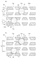
- FIG. 1 schematically shows the internal structure of a hydrodesulfurization catalyst structure according to an embodiment of the present invention.
- FIG. 1 (a) is a perspective view (partially in cross section).
- FIG. 1B is a partially enlarged sectional view.
- FIG. 2 is a partially enlarged cross-sectional view for explaining an example of the function of the catalyst structure of FIG. 1,
- FIG. 2 (a) is a diagram illustrating the sieve function, and
- FIG. 2 (b) is a diagram illustrating the catalytic ability.
- FIG. 3 is a flowchart showing an example of a method for producing the catalyst structure of FIG.
- FIG. 4 is a schematic view showing a modification of the catalyst structure of FIG.
- FIG. 1 is a diagram schematically showing a configuration of a hydrodesulfurization catalyst structure according to an embodiment of the present invention, in which (a) is a perspective view (a part is shown in cross section), and (b) is a diagram. It is a partial expanded sectional view. Note that the catalyst structure in FIG. 1 shows an example, and the shape, dimensions, etc. of each component according to the present invention are not limited to those in FIG.
- a hydrodesulfurization catalyst structure 1 (hereinafter simply referred to as a catalyst structure) includes a porous structure carrier 10 composed of a zeolite-type compound, and an internal structure of the carrier 10. And at least one catalytic material 20.
- the catalyst material 20 may be any material having catalytic ability (catalytic activity), and is preferably metal oxide fine particles or metal fine particles. Details of the metal oxide fine particles will be described later.
- the carrier 10 has a porous structure and, as shown in FIG. 1 (b), preferably has a plurality of holes 11a, 11a,.
- the catalyst material 20 exists in at least the passage 11 of the carrier 10, and is preferably held in at least the passage 11 of the skeleton 10.
- the movement of the catalyst material 20 in the carrier 10 is restricted, and the aggregation of the catalyst materials 20 and 20 is effectively prevented.
- a reduction in the effective surface area of the catalyst material 20 can be effectively suppressed, and the catalytic activity of the catalyst material 20 lasts for a long time. That is, according to the catalyst structure 1, it is possible to suppress a decrease in the catalyst activity due to the aggregation of the catalyst material 20, and to extend the life of the catalyst structure 1. Further, by extending the life of the catalyst structure 1, the replacement frequency of the catalyst structure 1 can be reduced, the amount of used catalyst structure 1 discarded can be greatly reduced, and resource saving can be achieved. .
- the catalyst structure when the catalyst structure is used in a fluid (for example, heavy oil or a reformed gas such as NOx), there is a possibility of receiving an external force from the fluid. In this case, there is a problem that if the catalyst substance is only held on the outer surface of the carrier 10 in an adhering state, it is likely to be detached from the outer surface of the carrier 10 due to the external force from the fluid. On the other hand, in the catalyst structure 1, since the catalyst material 20 is held in at least the passage 11 of the carrier 10, the catalyst material 20 is unlikely to be detached from the carrier 10 even under the influence of an external force due to the fluid.
- a fluid for example, heavy oil or a reformed gas such as NOx
- the fluid flows into the passage 11 from the hole 11a of the carrier 10, so that the speed of the fluid flowing in the passage 11 depends on the flow path resistance (friction force). This is considered to be slower than the speed of the fluid flowing on the outer surface of the carrier 10. Due to the influence of the flow path resistance, the pressure that the catalytic material 20 held in the passage 11 receives from the fluid is lower than the pressure that the catalytic material receives from the fluid outside the carrier 10. For this reason, it is possible to effectively suppress the separation of the catalyst substance 20 existing in the carrier 11, and it is possible to stably maintain the catalytic activity of the catalyst substance 20 for a long period of time.
- the flow path resistance as described above is considered to increase as the passage 11 of the carrier 10 has a plurality of bends and branches and the inside of the carrier 10 has a more complicated and three-dimensional structure. .
- the passage 11 includes any one of a one-dimensional hole, a two-dimensional hole, and a three-dimensional hole defined by a skeleton structure of the zeolite type compound, and the one-dimensional hole, the two-dimensional hole, and the three-dimensional hole.
- the catalyst material 20 is present at least in the diameter-expanded portion 12 and is at least enclosed by the diameter-expanded portion 12. It is more preferable.
- a one-dimensional hole means a tunnel-type or cage-type hole forming a one-dimensional channel, or a plurality of tunnel-type or cage-type holes forming a plurality of one-dimensional channels (a plurality of one-dimensional holes). Channel).
- a two-dimensional hole refers to a two-dimensional channel in which a plurality of one-dimensional channels are two-dimensionally connected.
- a three-dimensional hole refers to a three-dimensional channel in which a plurality of one-dimensional channels are three-dimensionally connected. Point to.
- FIG. 1B shows a case where the catalyst material 20 is enclosed by the enlarged diameter portion 12, the present invention is not limited to this configuration, and the catalyst material 20 is partially composed of the enlarged diameter portion 12. You may exist in the channel
- the passage 11 is formed in a three-dimensional manner inside the carrier 10 including a branch portion or a merge portion, and the enlarged diameter portion 12 is preferably provided in the branch portion or the merge portion of the passage 11. .
- the average inner diameter DF of the passage 11 formed in the carrier 10 is calculated from the average value of the short diameter and the long diameter of the hole 11a constituting any one of the one-dimensional hole, the two-dimensional hole, and the three-dimensional hole.
- the thickness is 0.1 nm to 1.5 nm, preferably 0.5 nm to 0.8 nm.
- the inner diameter DE of the enlarged diameter portion 12 is, for example, 0.5 nm to 50 nm, preferably 1.1 nm to 40 nm, more preferably 1.1 nm to 3.3 nm.
- the inner diameter D E of the enlarged diameter section 12 depends on for example the pore size of which will be described later precursor material (A), and the average particle diameter D C of the catalytic material 20 to be inclusion.
- the inner diameter DE of the enlarged diameter portion 12 is a size that can enclose the catalyst material 20.
- the carrier 10 is composed of a zeolite type compound.
- Zeolite type compounds include, for example, zeolites (aluminosilicates), cation exchange zeolites, silicate compounds such as silicalite, zeolite related compounds such as aluminoborate, aluminoarsenate, germanate, molybdenum phosphate, etc. And phosphate-based zeolite-like substances.
- the zeolite type compound is preferably a silicate compound.
- the framework structure of zeolite type compounds is FAU type (Y type or X type), MTW type, MFI type (ZSM-5), FER type (ferrierite), LTA type (A type), MWW type (MCM-22) , MOR type (mordenite), LTL type (L type), BEA type (beta type), etc., preferably MFI type, more preferably ZSM-5.
- a plurality of pores having a pore size corresponding to each skeleton structure are formed.
- the maximum pore size of the MFI type is 0.636 nm (6.36 mm), and the average pore size is 0.560 nm (5.60 mm). is there.
- the catalyst material 20 is metal oxide fine particles
- the metal oxide fine particle may be a primary particle or a secondary particle formed by aggregation of the primary particles.
- the diameter D C is preferably larger than the average inner diameter D F of the passage 11 and equal to or smaller than the inner diameter D E of the enlarged diameter portion 12 (D F ⁇ D C ⁇ D E ).
- Such metal oxide fine particles are preferably enclosed by the enlarged diameter portion 12 in the passage 11, and movement of the metal oxide fine particles in the carrier 10 is restricted. Therefore, even when the metal oxide fine particles receive an external force from the fluid, the movement of the metal oxide fine particles in the carrier 10 is suppressed, and the enlarged diameter portions 12 and 12 dispersedly arranged in the passage 11 of the carrier 10. It is possible to effectively prevent the metal oxide fine particles included in each of.
- the average particle diameter D C of the metal oxide fine particles in both cases the primary particles and the secondary particles is preferably 0.1 nm ⁇ 50 nm, more preferably less than 30nm over 0.1 nm, more preferably Is from 0.5 nm to 14.0 nm, particularly preferably from 1.0 nm to 3.3 nm.
- the ratio of the average particle diameter D C of the metal oxide fine particles to the average inner diameter D F of the passage 11 (D C / D F ) is preferably 0.06 to 500, more preferably 0.1 to 36. More preferably, it is 1.1 to 36, and particularly preferably 1.7 to 4.5.
- the metal element (M) of the metal oxide fine particles is preferably contained at 0.5 to 2.5% by mass with respect to the catalyst structure 1. More preferably, the content is 0.5 to 1.5 mass% with respect to the catalyst structure 1.
- the metal element (M) is Co
- the content (mass%) of the Co element is represented by ⁇ (mass of Co element) / (mass of all elements of the catalyst structure 1) ⁇ ⁇ 100. .
- the metal oxide fine particles may be composed of a metal oxide, for example, may be composed of a single metal oxide, or may be composed of a mixture of two or more metal oxides. Good.
- the “metal oxide” (as a material) constituting the metal oxide fine particles includes an oxide containing one kind of metal element (M) and two or more kinds of metal elements (M). This is a generic name for oxides containing one or more metal elements (M).
- the metal oxide fine particles preferably contain a metal oxide composed of at least one of nickel, cobalt, molybdenum, and tungsten.
- the metal oxide fine particles include a metal oxide composed of two or more of the above metal species, the metal oxide can be referred to as a composite metal oxide.
- the metal oxide fine particles are mainly composed of a molybdenum-based (M-Mo-based) oxide and / or a tungsten-based (MW-based) oxide, where M is nickel, cobalt, copper and zinc. Of these, it is more preferable to be composed of a combination of two or more.
- the metal component is preferably a combination of nickel-molybdenum, cobalt-molybdenum, nickel-molybdenum-cobalt, nickel-tungsten, cobalt-tungsten, nickel-tungsten-cobalt, etc.
- a combination of nickel-molybdenum, cobalt-molybdenum, and nickel-molybdenum-cobalt is preferable.
- the metal component is nickel - - the metal component of nickel when a combination of tungsten, and the metal oxide for example is NiWO 4.
- the ratio of silicon (Si) constituting the carrier 10 to the metal element (M) constituting the metal oxide fine particles is preferably 10 to 1000, preferably 50 to 200. More preferably. If the ratio is greater than 1000, the activity as a catalyst substance may not be sufficiently obtained, such as low activity. On the other hand, if the ratio is less than 10, the ratio of the metal oxide fine particles becomes too large, and the strength of the carrier 10 tends to decrease.
- the metal oxide fine particles referred to here are metal oxide fine particles held or supported inside the carrier 10, and do not include metal oxide fine particles attached to the outer surface of the carrier 10.
- the catalyst material 20 is mainly composed of a molybdenum-based (M-Mo-based) and / or tungsten-based (MW-based) metal, and M is any one of nickel, cobalt, copper, and zinc, or You may be comprised by the combination of 2 or more types.
- M-Mo-based molybdenum-based
- MW-based molybdenum-based
- MW-based molybdenum-based
- MW-based metal component any one of nickel, cobalt, copper, and zinc
- M-based any one of nickel, cobalt, copper, and zinc
- You may be comprised by the combination of 2 or more types.
- specific examples of the metal component (MW or M-Mo) are the same as above, nickel-molybdenum, cobalt-molybdenum, nickel-molybdenum-cobalt, nickel-tungsten, cobalt-tungsten, nickel-tungsten-cobalt.
- the catalyst structure 1 includes the support 10 having a porous structure and at least one catalyst substance 20 inherent in the support.
- the catalyst structure 1 exhibits catalytic activity corresponding to the catalyst material 20 when the catalyst material 20 existing in the carrier comes into contact with the fluid. Specifically, the fluid that has contacted the outer surface 10a of the catalyst structure 1 flows into the carrier 10 through the holes 11a formed in the outer surface 10a, is guided into the passage 11, and moves through the passage 11. Then, it goes out of the catalyst structure 1 through another hole 11a.
- a reaction for example, a catalytic reaction
- the catalyst structure 1 has molecular sieving ability because the carrier has a porous structure.
- the catalyst structure 1 has a molecular sieving ability that permeates predetermined molecules contained in heavy oil such as crude oil or residual oil.
- the molecular sieving ability of the catalyst structure 1 will be described with reference to FIG. 2A as an example where the fluid is a liquid containing benzene, propylene and mesitylene.
- a compound for example, benzene, propylene
- a compound composed of molecules having a size smaller than the diameter of the hole 11a, in other words, smaller than the inner diameter of the passage 11, enters the carrier 10. be able to.
- a compound (for example, mesitylene) composed of molecules having a size exceeding the pore diameter of the pores 11 a cannot enter the carrier 10.
- the reaction of the compound that cannot enter the carrier 10 is restricted, and the compound that can enter the carrier 10 can be reacted.
- the catalyst material 20 is enclosed by the enlarged diameter portion 12 of the passage 11.
- the catalytic material 20 is a metal oxide fine particles
- the average particle diameter D C of the metal oxide fine particles is larger than the average inner diameter D F of the passage 11 is smaller than the inner diameter D E of the enlarged diameter portion 12 ( D F ⁇ D C ⁇ D E )
- a small passage 13 is formed between the metal oxide fine particles and the enlarged diameter portion 12. Therefore, as shown by the arrow in FIG. 2B, the fluid that has entered the small passage 13 comes into contact with the metal oxide fine particles. Since each metal oxide fine particle is enclosed by the enlarged diameter part 12, the movement in the support
- the molecules that have entered the passage 11 come into contact with the catalyst material 20, the molecules (substance to be reformed) are reformed by a desulfurization reaction that occurs in a hydrogen molecule environment.
- a desulfurization reaction that occurs in a hydrogen molecule environment.
- NiWO 4 contained in the catalyst material 20 is used as a catalyst, sulfur components such as thiol and disulfide are removed from petroleum components.
- crude oil, heavy oil, etc. can be reformed.
- FIG. 3 is a flowchart showing a method for manufacturing the catalyst structure 1 of FIG.
- an example of a method for producing a catalyst structure will be described, taking as an example the case where the catalyst substance present in the carrier is metal oxide fine particles.
- Step S1 Preparation process
- a precursor material (A) for obtaining a porous support composed of a zeolite-type compound is prepared.
- the precursor material (A) is preferably a regular mesoporous material, and can be appropriately selected according to the type (composition) of the zeolite-type compound constituting the support of the catalyst structure.
- the regular mesoporous material when the zeolitic compound constituting the support of the catalyst structure is a silicate compound, the regular mesoporous material has a one-dimensional, two-dimensional or three-dimensional pore having a pore diameter of 1 to 50 nm. It is preferably a compound composed of a Si—O skeleton having a uniform size and regularly developed.
- Such regular mesoporous materials can be obtained as various composites depending on the synthesis conditions. Specific examples of the composites include, for example, SBA-1, SBA-15, SBA-16, KIT-6, FSM- 16, MCM-41, etc., among which MCM-41 is preferable.
- the pore diameter of SBA-1 is 10 to 30 nm
- the pore diameter of SBA-15 is 6 to 10 nm
- the pore diameter of SBA-16 is 6 nm
- the pore diameter of KIT-6 is 9 nm
- the pore diameter of FSM-16 is 3
- the pore diameter of MCM-41 is 1 to 10 nm.
- regular mesoporous materials include mesoporous silica, mesoporous aluminosilicate, and mesoporous metallosilicate.
- the precursor material (A) may be a commercially available product or a synthetic product.
- the precursor material (A) can be performed by a known method for synthesizing regular mesoporous materials. For example, a mixed solution containing a raw material containing the constituent elements of the precursor material (A) and a templating agent for defining the structure of the precursor material (A) is prepared, and the pH is adjusted as necessary. Hydrothermal treatment (hydrothermal synthesis) is performed. Thereafter, the precipitate (product) obtained by hydrothermal treatment is recovered (for example, filtered), washed and dried as necessary, and further calcined to form a regular mesoporous material in powder form. A precursor material (A) is obtained.
- a solvent of the mixed solution for example, water, an organic solvent such as alcohol, or a mixed solvent thereof can be used.
- a raw material is selected according to the kind of support
- carrier for example, silica agents, such as tetraethoxysilane (TEOS), fumed silica, quartz sand, etc. are mentioned.
- TEOS tetraethoxysilane
- templating agent various surfactants, block copolymers and the like can be used, and it is preferable to select according to the kind of the compound of the regular mesoporous material.
- a surfactant such as hexadecyltrimethylammonium bromide is preferred.
- the hydrothermal treatment can be performed, for example, in a sealed container at 80 to 800 ° C., 5 hours to 240 hours, and treatment conditions of 0 to 2000 kPa.
- the baking treatment can be performed, for example, in air at 350 to 850 ° C. for 2 hours to 30 hours.
- Step S2 impregnation step
- the prepared precursor material (A) is impregnated with the metal-containing solution to obtain the precursor material (B).
- the metal-containing solution may be a solution containing a metal component (for example, metal ion) corresponding to the metal element (M) constituting the metal oxide fine particles of the catalyst structure.
- the metal element (M ) can be prepared by dissolving the metal salt.
- metal salts include metal salts such as chlorides, hydroxides, oxides, sulfates, nitrates, etc. Among them, nitrates are preferable.
- the solvent for example, water, an organic solvent such as alcohol, or a mixed solvent thereof can be used.
- the method for impregnating the precursor material (A) with the metal-containing solution is not particularly limited.
- a plurality of metal-containing solutions are mixed while stirring the powdery precursor material (A) before the firing step described later. It is preferable to add in small portions in portions.
- a surfactant as an additive is added in advance to the precursor material (A) before adding the metal-containing solution. It is preferable to add it.
- Such an additive has a function of coating the outer surface of the precursor material (A), suppresses the metal-containing solution added thereafter from adhering to the outer surface of the precursor material (A), and the metal It is considered that the contained solution is more likely to enter the pores of the precursor material (A).
- nonionic surfactants such as polyoxyethylene oleyl ether, polyoxyethylene alkyl ether, and polyoxyethylene alkylphenyl ether. Since these surfactants have a large molecular size and cannot penetrate into the pores of the precursor material (A), they do not adhere to the inside of the pores, and the metal-containing solution penetrates into the pores. It is thought not to interfere.
- the nonionic surfactant is preferably added in an amount of 50 to 500% by mass with respect to the precursor material (A) before the firing step described later.
- the addition amount of the nonionic surfactant to the precursor material (A) is less than 50% by mass, the above-described inhibitory action is hardly exhibited, and the nonionic surfactant is added to the precursor material (A) at 500. Addition of more than% by mass is not preferable because the viscosity increases excessively. Therefore, the addition amount of the nonionic surfactant with respect to the precursor material (A) is set to a value within the above range.
- the amount of the metal-containing solution added to the precursor material (A) is the amount of the metal element (M) contained in the metal-containing solution impregnated in the precursor material (A) (that is, the precursor material (B It is preferable to adjust appropriately in consideration of the amount of the metal element (M) contained in ().
- the addition amount of the metal-containing solution added to the precursor material (A) is the metal element (M) contained in the metal-containing solution added to the precursor material (A)
- the ratio of silicon (Si) constituting the precursor material (A) atomic ratio Si / M
- it is preferably adjusted to be 10 to 1000, and adjusted to be 50 to 200. It is more preferable.
- the addition of the metal-containing solution to be added to the precursor material (A) When the amount is 50 to 200 in terms of the atomic ratio Si / M, the metal element (M) of the metal oxide fine particles is contained at 0.5 to 2.5 mass% with respect to the catalyst structure. Can be made.
- the amount of the metal element (M) present in the pores is the same as the metal concentration of the metal-containing solution, the presence or absence of the additive, and other conditions such as temperature and pressure. If so, it is roughly proportional to the amount of the metal-containing solution added to the precursor material (A).
- the amount of the metal element (M) inherent in the precursor material (B) is proportional to the amount of the metal element constituting the metal oxide fine particles inherent in the support of the catalyst structure. Therefore, by controlling the amount of the metal-containing solution added to the precursor material (A) within the above range, the metal-containing solution can be sufficiently impregnated inside the pores of the precursor material (A), and thus It is possible to adjust the amount of metal oxide fine particles incorporated in the support of the catalyst structure.
- a cleaning treatment may be performed as necessary.
- the cleaning solution water, an organic solvent such as alcohol, or a mixed solution thereof can be used.
- the drying treatment include natural drying overnight or high temperature drying at 150 ° C. or lower.
- the regular mesopores of the precursor material (A) are obtained by performing the baking treatment described later in a state where a large amount of moisture contained in the metal-containing solution and the moisture of the cleaning solution remain in the precursor material (A). Since the skeletal structure as a substance may be broken, it is preferable to dry it sufficiently.
- Step S3 Firing step
- the precursor material (B) obtained by impregnating the precursor material (A) for impregnating the porous material structure composed of the zeolite type compound with the metal-containing solution is calcined to obtain the precursor material (C). Get.
- the calcination treatment is preferably performed, for example, in air at 350 to 850 ° C. for 2 hours to 30 hours.
- the metal component impregnated in the pores of the regular mesoporous material grows in crystal, and metal oxide fine particles are formed in the pores.
- Step S4 Hydrothermal treatment process
- a mixed solution in which the precursor material (C) and the structure directing agent are mixed is prepared, and the precursor material (C) obtained by firing the precursor material (B) is hydrothermally treated to form a catalyst structure. Get the body.
- the structure directing agent is a templating agent for defining the skeletal structure of the support of the catalyst structure, and for example, a surfactant can be used.
- the structure directing agent is preferably selected according to the skeleton structure of the support of the catalyst structure.
- a surfactant such as tetramethylammonium bromide (TMABr), tetraethylammonium bromide (TEABr), tetrapropylammonium bromide (TPABr), etc. Is preferred.
- the mixing of the precursor material (C) and the structure directing agent may be performed during the hydrothermal treatment step or before the hydrothermal treatment step.
- the preparation method of the said mixed solution is not specifically limited, A precursor material (C), a structure directing agent, and a solvent may be mixed simultaneously, or precursor material (C) and structure prescription
- each agent is dispersed in each solution, each dispersion solution may be mixed.
- the solvent for example, water, an organic solvent such as alcohol, or a mixed solvent thereof can be used.
- the pH of the mixed solution is preferably adjusted using an acid or a base before hydrothermal treatment.
- the hydrothermal treatment can be performed by a known method.
- the hydrothermal treatment is preferably performed in a sealed container at 80 to 800 ° C., 5 hours to 240 hours, and 0 to 2000 kPa.
- the hydrothermal treatment is preferably performed in a basic atmosphere.
- the reaction mechanism here is not necessarily clear, by performing hydrothermal treatment using the precursor material (C) as a raw material, the skeleton structure of the precursor material (C) as a regular mesoporous material gradually collapses. While the position of the metal oxide fine particles inside the pores of the precursor material (C) is generally maintained, a new skeletal structure (porous structure) is formed as a support for the catalyst structure by the action of the structure directing agent. Is done.
- the catalyst structure thus obtained includes a porous structure carrier and metal oxide fine particles inherent in the carrier, and the carrier has a passage in which a plurality of pores communicate with each other due to the porous structure. At least a part of the metal oxide fine particles is present in the passage of the carrier.
- a mixed solution in which the precursor material (C) and the structure directing agent are mixed is prepared, and the precursor material (C) is hydrothermally treated.
- the precursor material (C) may be hydrothermally treated without mixing the precursor material (C) and the structure directing agent.
- the precipitate (catalyst structure) obtained after the hydrothermal treatment is preferably recovered (for example, filtered), then washed, dried and fired as necessary.
- the cleaning solution water, an organic solvent such as alcohol, or a mixed solution thereof can be used.
- the drying treatment include natural drying overnight or high temperature drying at 150 ° C. or lower.
- the calcination treatment is performed in a state where a large amount of moisture remains in the precipitate, the skeletal structure as the support of the catalyst structure may be broken. Therefore, it is preferable that the precipitate is sufficiently dried.
- the firing treatment can be performed, for example, in air at 350 to 850 ° C. for 2 hours to 30 hours.
- the structure directing agent attached to the catalyst structure is burned away.
- the catalyst structure can be used as it is without subjecting the recovered precipitate to a firing treatment depending on the purpose of use. For example, if the environment in which the catalyst structure is used is a high-temperature environment in an oxidizing atmosphere, the structure directing agent will be burned down by exposure to the environment for a certain period of time. Since it is obtained, it can be used as it is.
- the manufacturing method described above is an example in the case where the metal element (M) contained in the metal-containing solution impregnated in the precursor material (A) is a metal species that is not easily oxidized (for example, a noble metal).
- the metal element (M) contained in the metal-containing solution impregnated in the precursor material (A) is a metal species that is easily oxidized (for example, Fe, Co, Cu, etc.), after the hydrothermal treatment, It is preferable to perform a reduction treatment.
- the metal element (M) contained in the metal-containing solution is a metal species that is easily oxidized, the metal component is oxidized by the heat treatment in the steps (steps S3 to S4) after the impregnation treatment (step S2). . Therefore, metal oxide fine particles are inherent in the skeleton formed in the hydrothermal treatment step (step S4).
- Step S5 Reduction process
- the metal oxide fine particles present in the skeleton are reduced, and metal fine particles corresponding to the metal element (M) constituting the metal oxide fine particles are formed.
- M metal element
- Such reduction treatment may be performed as necessary.
- the environment in which the functional structure is used is a reducing atmosphere, the metal oxide fine particles are exposed to the usage environment for a certain period of time. Therefore, since the functional structure similar to that obtained by the reduction treatment is obtained, it can be used as it is with the oxide fine particles inherent in the skeleton.
- FIG. 4 is a schematic view showing a modification of the catalyst structure 1 of FIG.
- the catalyst structure 1 in FIG. 1 shows a case in which a support 10 and a catalyst substance 20 inherent in the support 10 are provided.
- the present invention is not limited to this configuration.
- the structure 2 may further include another catalyst material 30 held on the outer surface 10 a of the carrier 10.
- the catalyst substance 30 is a substance that exhibits one or more catalytic ability.
- the catalytic ability of the other catalytic material 30 may be the same as or different from the catalytic ability of the catalytic material 20. Further, when both of the catalyst substances 20 and 30 are substances having the same catalytic ability, the material of the other catalyst substance 30 may be the same as or different from the material of the catalyst substance 20. According to this configuration, the content of the catalyst material held in the catalyst structure 2 can be increased, and the catalytic activity of the catalyst material can be further promoted.
- the content of the catalyst substance 20 existing in the carrier 10 is larger than the contents of the other catalyst substances 30 held on the outer surface 10a of the carrier 10. As a result, the catalytic ability of the catalytic material 20 held inside the carrier 10 becomes dominant, and the catalytic ability of the catalytic material is stably exhibited.
- the catalytic material 20 is present in the passage 11 of the carrier 10, aggregation (sintering) of the catalytic materials 20 can be prevented, and a reduction in catalytic activity is suppressed to improve efficiency.
- a typical hydrodesulfurization treatment can be realized.
- the catalytic material 20 is a metal oxide fine particles
- average primary particle diameter D C of the metal oxide fine particles is larger than the average inner diameter D F of the passage 11, and is equal to or smaller than the inner diameter D E of the enlarged diameter portion 12 Therefore, the metal oxide fine particles can be reliably included in the enlarged diameter portion 12, and aggregation of the metal oxide fine particles can be reliably prevented.
- the catalytic function of the metal oxide fine particles can be maximized.
- hydrodesulfurization treatment of the heavy component which has not been sufficiently utilized so far can be promoted, such as desulfurized naphtha, desulfurized kerosene, desulfurized.
- the yield of light oil, desulfurized heavy oil, etc. can be improved.
- the metal oxide fine particles include a metal oxide composed of at least one of nickel, cobalt, molybdenum and tungsten, preferably a tungsten-based (MW-based) oxide and / or Alternatively, when a molybdenum-based (M-Mo-based) oxide is a main component and M is composed of any one of nickel, cobalt, copper, and zinc, or a combination of two or more thereof, metal oxide fine particles
- M-Mo-based oxide molybdenum-based oxide
- M-Mo-based oxide molybdenum-based oxide
- the desulfurization ability is improved by enclosing the expanded diameter portion 12, the generation of coke can be suppressed, and the decrease in the catalyst life due to the heat treatment can be suppressed.
- the appearance of the catalyst structure is powder, but is not limited thereto, and may be a cylindrical shape, a leaf shape, a dumbbell column shape, or a ring-shaped pellet shape.
- the method for forming the catalyst structure is not particularly limited in order to obtain the above-mentioned shape, but a general method such as extrusion, tableting, or granulation in oil can be used. Further, for example, after a catalyst powder is molded with a uniaxial pressurizer to prepare a catalyst structure, the catalyst molded body is passed through a sieve while being crushed, and at least one secondary particle having a target secondary particle diameter is used. You may obtain the method of obtaining the catalyst structure comprised.
- a state in which the catalyst structure is granulated by the above method can be referred to as a catalyst structure or a catalyst molded body.
- a catalyst structure having an average particle diameter (or an average of equivalent circle diameters) of, for example, 100 ⁇ m to 15 cm can be formed.
- a binder such as alumina may be mixed and molded.
- the catalyst structure or catalyst molded body has the shape and dimensions described above, so that when the crude oil, heavy oil, or a fraction obtained by distilling crude oil is desulfurized, the heavy oil fraction is prevented from clogging the catalyst layer. be able to.
- the hydrodesulfurization apparatus which has the said catalyst structure for hydrodesulfurization may be provided.
- the hydrodesulfurization apparatus is, for example, a reactor arranged downstream of a distillation apparatus in an oil refinery plant, and a substance supply unit to which a substance (hydrocarbon) separated by the distillation apparatus is supplied, and hydrogen gas is supplied.
- the hydrodesulfurization catalyst structure can be used in the reactor of the apparatus having such a configuration. That is, by supplying crude oil, heavy oil or a fraction obtained by distilling these to the catalyst structure, the component can be desulfurized.
- the catalyst structure can be used in a hydrodesulfurization apparatus, crude oil, By desulfurizing heavy oil or a fraction obtained by distilling them with the hydrodesulfurization apparatus, the same effects as described above can be achieved.
- type of precursor material (A) (“type of precursor material (A): surfactant”).
- CTL-41 hexadecyltrimethylammonium bromide (CTAB) (manufactured by Wako Pure Chemical Industries, Ltd.)
- SBA-1 Pluronic P123 (BASF)
- metal element (M) constituting the type of metal oxide fine particles shown in Tables 1 to 8
- metal salt containing the metal element (M) is dissolved in water to obtain a metal-containing aqueous solution.
- the following metal salts were used according to the type of metal oxide fine particles (“metal oxide fine particles: metal salt”).
- NiMo nickel nitrate (II) hexahydrate (manufactured by Wako Pure Chemical Industries, Ltd.), Na 2 MoO 4 ⁇ 2H 2 O molybdenum (VI) disodium dihydrate (manufactured by Wako Pure Chemical Industries, Ltd.)
- NiW Nickel (II) nitrate hexahydrate (Wako Pure Chemical Industries, Ltd.), ammonium metatungstate hydrate (Wako Pure Chemical Industries, Ltd.)
- CoMo Cobalt nitrate (II) hexahydrate (manufactured by Wako Pure Chemical Industries, Ltd.), Na 2 MoO 4 ⁇ 2H 2 O molybdenum (VI) disodium dihydrate (manufactured by Wako Pure Chemical Industries, Ltd.)
- CoW cobalt nitrate (II) hexahydrate (Wako Pure Chemical Industries, Ltd.), ammonium metatungstate hydrate (Wako Pure Chemical Industries, Ltd.)
- the metal-containing aqueous solution is added to the powdery precursor material (A) in small portions in small portions, and dried at room temperature (20 ° C. ⁇ 10 ° C.) for 12 hours or more to obtain the precursor material (B).
- polyoxyethylene (15) as an additive with respect to the precursor material (A) before adding the metal-containing aqueous solution Pretreatment was performed by adding an aqueous solution of oleyl ether (NIKKOL BO-15V, manufactured by Nikko Chemicals Co., Ltd.), and then the metal-containing aqueous solution was added as described above. In the case of “None” in the presence or absence of the additive, the pretreatment with the additive as described above is not performed.
- the addition amount of the metal-containing aqueous solution added to the precursor material (A) is the ratio of silicon (Si) constituting the precursor material (A) to the metal element (M) contained in the metal-containing aqueous solution (
- the numerical values when converted to the atomic ratio (Si / M) were adjusted to the values shown in Tables 1-8.
- precursor material (B) impregnated with the metal-containing aqueous solution obtained as described above was fired in the air at 600 ° C. for 24 hours to obtain a precursor material (C).
- Comparative Example 1 Comparative Example 1, cobalt oxide powder (II, III) (manufactured by Sigma Aldrich Japan LLC) having an average particle size of 50 nm or less was mixed with MFI type silicalite, and the catalyst substance was formed on the outer surface of silicalite as a skeleton. A catalyst structure to which cobalt oxide fine particles were adhered was obtained. MFI type silicalite was synthesized in the same manner as in Examples 52 to 57 except for the step of adding metal.
- Comparative Example 2 MFI type silicalite was synthesized by the same method as Comparative Example 1 except that the step of attaching the cobalt oxide fine particles was omitted.
- the catalyst structure in which the metal oxide is Ni—Mo oxide fine particles is cut out by FIB (focused ion beam) processing, and SEM (SU8020, manufactured by Hitachi High-Technologies Corporation), EDX ( Cross-sectional elemental analysis was performed using X-Max (manufactured by Horiba, Ltd.). As a result, Ni element and Mo element were detected from the inside of the skeleton. From the results of cross-sectional observation using the TEM and SEM / EDX, it was confirmed that Ni—Mo oxide fine particles were present inside the support.
- M Co, Ni, Fe, Cu
- a catalyst structure in which metal oxide fine particles are included inside the carrier is prepared in an amount, and then the amount of metal (mass%) included in the carrier of the catalyst structure produced in the above addition amount is measured. did.
- the amount of metal was determined by using ICP (high frequency inductively coupled plasma) alone or a combination of ICP and XRF (fluorescence X-ray analysis).
- XRF energy dispersive X-ray fluorescence spectrometer “SEA1200VX”, manufactured by SSI Nanotechnology Inc.) was performed under the conditions of a vacuum atmosphere, an acceleration voltage of 15 kV (using a Cr filter), or an acceleration voltage of 50 kV (using a Pb filter).
- Catalytic activity was evaluated under the following conditions. First, 0.2 g of the catalyst structure is charged into an atmospheric pressure flow reactor, nitrogen gas (N 2 ) is used as a carrier gas (5 ml / min), 400 ° C., 2 hours, butylbenzene (heavy oil model) The substance was decomposed. After completion of the reaction, the collected product gas and product liquid were subjected to component analysis by gas chromatography mass spectrometry (GC / MS). Note that TRACE 1310GC (manufactured by Thermo Fisher Scientific Co., Ltd., detector: thermal conductivity detector) was used as the product gas analyzer, and TRACE DSQ (Thermo Fisher Scientific) was used as the product liquid analyzer.
- GC / MS gas chromatography mass spectrometry
- the yield of the above compound is expressed as a percentage (mol%) of the total amount (mol) of a compound having a molecular weight smaller than that of butylbenzene contained in the product solution with respect to the amount (mol) of butylbenzene before the start of the reaction. Calculated.
- the yield of the compound having a molecular weight smaller than that of butylbenzene contained in the product solution is 40 mol% or more, it is determined that the catalytic activity (resolution) is excellent, and “ ⁇ ”, 25 mol%
- the catalyst activity is good, the catalyst activity is good when it is less than 40 mol%, and when the catalyst activity is not good when it is 10 mol% or more and less than 25 mol%, it is judged as acceptable level.
- “ ⁇ ” and less than 10 mol% the catalyst activity was judged to be inferior (impossible), and “x” was assigned.
- the yield of the compound by the catalyst structure after heating (the present evaluation (2)) relative to the yield of the compound by the catalyst structure before the heating (the yield obtained in the evaluation (1)).
- the percentage (%) of the yield obtained in step 1) was calculated.
- the yield of the above compound by the catalyst structure after heating (the yield determined in this evaluation (2)) is the yield of the above compound by the catalyst structure before heating (in the above evaluation (1)).
- Comparative Example 2 is a support itself and does not have a catalyst material. Therefore, in the performance evaluation, only the support of Comparative Example 2 was filled instead of the catalyst structure. The results are shown in Table 8.
- the catalyst structures (Examples 1 to 384) in which the catalytic material was confirmed to be retained inside the support by cross-sectional observation were simply put on the outer surface of the support.
- a catalyst structure that has only adhered (Comparative Example 1) or a skeleton that does not have any catalytic substance (Comparative Example 2), it exhibits an excellent catalytic activity in the decomposition reaction of butylbenzene. As a result, it was found to be excellent in durability.
- the amount of metal (mass%) enclosed in the support of the catalyst structure measured in the above evaluation [C], and the yield of the compound having a molecular weight smaller than that of butylbenzene contained in the product liquid (mol%) ) was evaluated.
- the evaluation method was the same as the evaluation method performed in “(1) Catalytic activity” in [D] “Performance evaluation”.
- the yield of the compound having a molecular weight smaller than that of butylbenzene contained in the product liquid is 32 mol% or more, and in the decomposition reaction of butylbenzene. It was found that the catalyst activity was above the acceptable level.
- the silicalite of Comparative Example 1 in which the catalyst material is attached only to the outer surface of the carrier has a catalytic activity in the decomposition reaction of butylbenzene, as compared with the carrier of Comparative Example 2 which does not have any catalyst material. Although improved, the durability as a catalyst was inferior to the catalyst structures of Examples 1 to 384.
- the catalyst structures exhibit excellent catalytic activity even in hydrodesulfurization activity and are excellent in durability as a catalyst.
- the catalyst structure includes a porous structure carrier composed of a zeolite-type compound and metal fine particles present in the carrier, the carrier has a passage communicating with each other, and the metal fine particles are formed on the carrier.
- the catalyst structure is used in a hydrodesulfurization unit, and a fraction obtained by distilling crude oil is desulfurized in the hydrodesulfurization unit, as described in (1) or (2) above A method using a catalyst structure.
- catalyst structure 10 carrier 10a outer surface 11 passage 11a hole 12 expanded diameter portion 20 catalytic material 30 catalytic material D C average particle diameter D F average inner diameter D E inner diameter
Landscapes
- Chemical & Material Sciences (AREA)
- Organic Chemistry (AREA)
- Chemical Kinetics & Catalysis (AREA)
- Engineering & Computer Science (AREA)
- Materials Engineering (AREA)
- Crystallography & Structural Chemistry (AREA)
- Oil, Petroleum & Natural Gas (AREA)
- General Chemical & Material Sciences (AREA)
- Physics & Mathematics (AREA)
- Thermal Sciences (AREA)
- Inorganic Chemistry (AREA)
- Geology (AREA)
- General Life Sciences & Earth Sciences (AREA)
- Life Sciences & Earth Sciences (AREA)
- Catalysts (AREA)
- Nanotechnology (AREA)
- Production Of Liquid Hydrocarbon Mixture For Refining Petroleum (AREA)
Priority Applications (4)
| Application Number | Priority Date | Filing Date | Title |
|---|---|---|---|
| JP2019521322A JP7316934B2 (ja) | 2017-05-31 | 2018-05-31 | 水素化脱硫用触媒構造体、該触媒構造体を備える水素化脱硫装置及び水素化脱硫用触媒構造体の製造方法 |
| EP18808738.1A EP3632555A4 (en) | 2017-05-31 | 2018-05-31 | HYDRO DESULFURIZATION CATALYST STRUCTURE, HYDRO DESULFURIZATION DEVICE PROVIDED WITH THIS CATALYST STRUCTURE, AND METHOD FOR MANUFACTURING A HYDRODESULFURIZATION CATALYST STRUCTURE |
| CN201880035360.1A CN110678263A (zh) | 2017-05-31 | 2018-05-31 | 加氢脱硫用催化剂结构体、具备该催化剂结构体的加氢脱硫装置、以及加氢脱硫用催化剂结构体的制造方法 |
| US16/698,468 US11680211B2 (en) | 2017-05-31 | 2019-11-27 | Structured catalyst for hydrodesulfurization, hydrodesulfurization device including the structured catalyst, and method for producing structured catalyst for hydrodesulfurization |
Applications Claiming Priority (2)
| Application Number | Priority Date | Filing Date | Title |
|---|---|---|---|
| JP2017-108601 | 2017-05-31 | ||
| JP2017108601 | 2017-05-31 |
Related Child Applications (1)
| Application Number | Title | Priority Date | Filing Date |
|---|---|---|---|
| US16/698,468 Continuation US11680211B2 (en) | 2017-05-31 | 2019-11-27 | Structured catalyst for hydrodesulfurization, hydrodesulfurization device including the structured catalyst, and method for producing structured catalyst for hydrodesulfurization |
Publications (1)
| Publication Number | Publication Date |
|---|---|
| WO2018221694A1 true WO2018221694A1 (ja) | 2018-12-06 |
Family
ID=64456335
Family Applications (1)
| Application Number | Title | Priority Date | Filing Date |
|---|---|---|---|
| PCT/JP2018/021082 WO2018221694A1 (ja) | 2017-05-31 | 2018-05-31 | 水素化脱硫用触媒構造体、該触媒構造体を備える水素化脱硫装置及び水素化脱硫用触媒構造体の製造方法 |
Country Status (5)
| Country | Link |
|---|---|
| US (1) | US11680211B2 (zh) |
| EP (1) | EP3632555A4 (zh) |
| JP (1) | JP7316934B2 (zh) |
| CN (1) | CN110678263A (zh) |
| WO (1) | WO2018221694A1 (zh) |
Families Citing this family (9)
| Publication number | Priority date | Publication date | Assignee | Title |
|---|---|---|---|---|
| JP7306990B2 (ja) | 2017-05-31 | 2023-07-11 | 古河電気工業株式会社 | Coシフトもしくは逆シフト触媒構造体及びその製造方法、coシフトまたは逆シフト反応装置、二酸化炭素と水素の製造方法、並びに一酸化炭素と水の製造方法 |
| CN110678258A (zh) | 2017-05-31 | 2020-01-10 | 国立大学法人北海道大学 | 功能性结构体以及功能性结构体的制造方法 |
| WO2018221706A1 (ja) | 2017-05-31 | 2018-12-06 | 古河電気工業株式会社 | メタノール改質触媒構造体、メタノール改質用装置、メタノール改質触媒構造体の製造方法及びオレフィンまたは芳香族炭化水素の少なくとも一方の製造方法 |
| WO2018221690A1 (ja) | 2017-05-31 | 2018-12-06 | 国立大学法人北海道大学 | 機能性構造体及び機能性構造体の製造方法 |
| JP7352909B2 (ja) | 2017-05-31 | 2023-09-29 | 国立大学法人北海道大学 | 機能性構造体及び機能性構造体の製造方法 |
| EP3632547A4 (en) | 2017-05-31 | 2020-12-16 | Furukawa Electric Co., Ltd. | CATALYST STRUCTURE FOR CATALYTIC CRACKING OR HYDRODESULFURATION, DEVICE FOR CATALYTIC CRACKING AND HYDRODESULFURATION DEVICE USING THE ABOVE CATALYST STRUCTURE AND MANUFACTURING PROCESSES FOR HYDRODESULFURATION |
| EP3632554A4 (en) | 2017-05-31 | 2021-04-21 | Furukawa Electric Co., Ltd. | EXHAUST GAS PURIFICATION OXIDATION CATALYST STRUCTURE AND PRODUCTION PROCESS, VEHICLE EXHAUST GAS TREATMENT DEVICE, CATALYST MOLDED BODY AND GAS PURIFICATION PROCESS. |
| CN110709165A (zh) | 2017-05-31 | 2020-01-17 | 国立大学法人北海道大学 | 功能性结构体以及功能性结构体的制造方法 |
| CN113164944A (zh) * | 2018-12-03 | 2021-07-23 | 国立大学法人北海道大学 | 功能性结构体 |
Citations (5)
| Publication number | Priority date | Publication date | Assignee | Title |
|---|---|---|---|---|
| JP2009505830A (ja) * | 2005-08-31 | 2009-02-12 | インステイチユート メキシカノ デル ペトロレオ | 石油留分の水素化転化のための触媒組成物を調製する方法 |
| JP2010527769A (ja) * | 2007-05-24 | 2010-08-19 | サウディ ベーシック インダストリーズ コーポレイション | 炭化水素を転化するためのGeゼオライト触媒、その製造方法および使用方法 |
| JP2016529190A (ja) * | 2013-07-05 | 2016-09-23 | ダンマークス・テクニスケ・ユニヴェルシテット | ゼオライト及びゼオ型を製造する方法 |
| JP2017064647A (ja) | 2015-09-30 | 2017-04-06 | Jxエネルギー株式会社 | 炭化水素油の水素化脱硫触媒およびその製造方法 |
| JP2017128480A (ja) * | 2016-01-20 | 2017-07-27 | 日揮触媒化成株式会社 | 金属粒子を内包したゼオライト |
Family Cites Families (116)
| Publication number | Priority date | Publication date | Assignee | Title |
|---|---|---|---|---|
| US3898180A (en) | 1970-07-23 | 1975-08-05 | Ici Ltd | Catalyst pellet |
| JPS5746925A (en) | 1980-09-03 | 1982-03-17 | Res Assoc Petroleum Alternat Dev<Rapad> | Preparation of hydrocarbon |
| US4552855A (en) | 1982-12-30 | 1985-11-12 | Ozin Geoffrey A | Metal zeolite catalyst preparation |
| US5026673A (en) | 1989-06-23 | 1991-06-25 | University Of Delaware | Stable zeolite-supported transition metal catalysts, methods for making them, and uses thereof |
| JP2771321B2 (ja) | 1990-11-09 | 1998-07-02 | 日本碍子株式会社 | 排気ガス浄化用触媒組成物、排気ガス浄化用触媒及びその製造方法 |
| US5275720A (en) | 1990-11-30 | 1994-01-04 | Union Oil Company Of California | Gasoline hydrocracking catalyst and process |
| US5236575A (en) | 1991-06-19 | 1993-08-17 | Mobil Oil Corp. | Synthetic porous crystalline mcm-49, its synthesis and use |
| JPH0549943A (ja) | 1991-08-20 | 1993-03-02 | Sakai Chem Ind Co Ltd | 酸化触媒 |
| JPH06142456A (ja) | 1992-11-08 | 1994-05-24 | Sekiyu Sangyo Kasseika Center | 排ガス中の窒素酸化物の除去方法 |
| JPH0796195A (ja) | 1993-09-29 | 1995-04-11 | Hino Motors Ltd | 排ガス浄化触媒 |
| JP2006021994A (ja) | 1993-12-28 | 2006-01-26 | Toto Ltd | 光触媒機能を有する多機能材の製造方法 |
| US5849652A (en) | 1994-03-14 | 1998-12-15 | Northeastern University | Metal containing catalysts and methods for making same |
| JPH08155303A (ja) | 1994-12-01 | 1996-06-18 | Toyota Central Res & Dev Lab Inc | 排ガス浄化用触媒担体と排ガス浄化用触媒及び排ガス浄化用触媒担体の製造方法ならびに排ガス浄化方法 |
| CN1223602A (zh) | 1996-05-29 | 1999-07-21 | 埃克森化学专利公司 | 含金属的沸石催化剂,其制备方法及其在烃转化中的应用 |
| DE69720998D1 (de) | 1996-05-29 | 2003-05-22 | Exxonmobil Chem Patents Inc | Herstellung von para-xylol durch methylierung von toluol |
| BR9709400A (pt) | 1996-05-29 | 1999-08-10 | Exxon Chemical Patents Inc | Catalisador de zeólito contendo metal preparação do mesmo e uso para convers o de hidrocarbonetos |
| JPH11151440A (ja) | 1997-07-18 | 1999-06-08 | Tokyo Gas Co Ltd | 窒素酸化物の分解除去用触媒及び窒素酸化物の分解除去方法 |
| JPH1133412A (ja) | 1997-07-23 | 1999-02-09 | Unitika Ltd | 金属担持触媒の製造方法 |
| JP2000197822A (ja) | 1999-01-08 | 2000-07-18 | Tokyo Gas Co Ltd | 窒素酸化物の分解除去用触媒及び窒素酸化物の分解除去方法 |
| JP3897143B2 (ja) | 1999-05-11 | 2007-03-22 | 富士電機ホールディングス株式会社 | 改質装置とその起動方法及び燃料電池発電装置 |
| US6930219B2 (en) | 1999-09-07 | 2005-08-16 | Abb Lummus Global Inc. | Mesoporous material with active metals |
| US7074373B1 (en) | 2000-11-13 | 2006-07-11 | Harvest Energy Technology, Inc. | Thermally-integrated low temperature water-gas shift reactor apparatus and process |
| FR2819432B1 (fr) | 2001-01-18 | 2003-04-11 | Rhodia Chimie Sa | Catalyseur mesostructure integrant des particules de dimensions nanometriques |
| JP2002255537A (ja) | 2001-02-22 | 2002-09-11 | National Institute Of Advanced Industrial & Technology | 固体酸触媒 |
| JP2002336704A (ja) | 2001-05-18 | 2002-11-26 | Masaru Ichikawa | メタンの芳香族化反応触媒およびその調製方法 |
| US6881703B2 (en) | 2001-08-08 | 2005-04-19 | Corning Incorporated | Thermally conductive honeycombs for chemical reactors |
| JP2003230838A (ja) | 2001-12-06 | 2003-08-19 | Denso Corp | セラミック触媒体 |
| AU2003301060A1 (en) | 2002-12-20 | 2004-07-22 | Honda Giken Kogyo Kabushiki Kaisha | Noble metal-free nickel catalyst formulations for hydrogen generation |
| JP2005170903A (ja) | 2003-12-15 | 2005-06-30 | Idemitsu Kosan Co Ltd | ビシクロ[2.2.1]ヘプタン誘導体の製造方法 |
| JP4334336B2 (ja) | 2003-12-26 | 2009-09-30 | 株式会社フジクラ | 光スイッチ |
| WO2005083013A1 (en) | 2004-01-30 | 2005-09-09 | Millennium Chemicals | Coating composition having surface depolluting properties |
| JP4469975B2 (ja) | 2004-03-23 | 2010-06-02 | 国立大学法人広島大学 | 光触媒複合体およびこれを用いた有機物質変換方法 |
| JP5194249B2 (ja) | 2004-03-29 | 2013-05-08 | 国立大学法人広島大学 | 複合多孔体およびその製造方法、並びにこれを用いた有機物質変換方法 |
| US20090325790A1 (en) | 2004-06-17 | 2009-12-31 | Yale University | Size-controllable transition metal clusters in mcm-41 for improving chemical catalysis |
| CN103059899A (zh) | 2005-03-16 | 2013-04-24 | 弗尔科有限责任公司 | 用于生产合成烃化合物的系统、方法及组合物 |
| CN101180125B (zh) | 2005-03-24 | 2014-09-10 | 里贾纳大学 | 用于生产氢的催化剂 |
| FR2886636B1 (fr) | 2005-06-02 | 2007-08-03 | Inst Francais Du Petrole | Materiau inorganique presentant des nanoparticules metalliques piegees dans une matrice mesostructuree |
| CN100392047C (zh) | 2005-06-09 | 2008-06-04 | 中国科学院大连化学物理研究所 | 一种石油烃类催化氧化裂解制烯烃的方法 |
| WO2007000847A1 (ja) | 2005-06-29 | 2007-01-04 | Ibiden Co., Ltd. | ハニカム構造体 |
| WO2007023558A1 (ja) | 2005-08-26 | 2007-03-01 | Suminoe Textile Co., Ltd. | 酸化タングステン系光触媒及びその製造方法並びに消臭・防汚機能を有する繊維布帛 |
| MY145567A (en) | 2005-09-16 | 2012-02-29 | Asahi Kasei Chemicals Corp | Method for producing ethylene and propylene |
| JP4879574B2 (ja) | 2005-09-16 | 2012-02-22 | 旭化成ケミカルズ株式会社 | エチレン及びプロピレンの製造方法 |
| JP2007130525A (ja) | 2005-11-08 | 2007-05-31 | Nissan Motor Co Ltd | 包接触媒及びその製造方法 |
| JP5076377B2 (ja) | 2006-07-03 | 2012-11-21 | トヨタ自動車株式会社 | 排ガス浄化触媒 |
| US7592291B2 (en) | 2006-08-15 | 2009-09-22 | Batelle Energy Alliance, Llc | Method of fabricating a catalytic structure |
| US7879749B2 (en) | 2006-08-15 | 2011-02-01 | Battelle Energy Alliance, Llc | Methods of using structures including catalytic materials disposed within porous zeolite materials to synthesize hydrocarbons |
| CN101130466B (zh) | 2006-08-23 | 2011-05-04 | 中国科学院大连化学物理研究所 | 制取低碳烯烃流态化催化反应装置的开工方法 |
| CN101362959B (zh) | 2007-08-09 | 2012-09-05 | 中国石油化工股份有限公司 | 一种制取丙烯和高辛烷值汽油的催化转化方法 |
| JP4943516B2 (ja) | 2008-02-01 | 2012-05-30 | 島津システムソリューションズ株式会社 | 銀−酸化チタン−ゼオライト吸着分解素材 |
| FR2929264B1 (fr) | 2008-03-31 | 2010-03-19 | Inst Francais Du Petrole | Materiau inorganique forme de particules spheriques de taille specifique et presentant des nanoparticules metalliques piegees dans une matrice mesostructuree |
| JP2009255014A (ja) | 2008-04-21 | 2009-11-05 | Mitsubishi Chemicals Corp | メタノールからオレフィンを製造するための触媒 |
| US8273932B2 (en) | 2008-06-10 | 2012-09-25 | Mitsui Chemicals, Inc. | Process for producing alkylated aromatic compounds and process for producing phenol |
| JP4639247B2 (ja) | 2008-07-23 | 2011-02-23 | 石油資源開発株式会社 | 炭化水素リフォーミング用触媒およびその製造方法ならびにこれを用いた合成ガスの製法 |
| JP2010099638A (ja) | 2008-10-27 | 2010-05-06 | Nissan Motor Co Ltd | 触媒、排ガス浄化用触媒及び触媒の製造方法 |
| WO2010097108A1 (en) * | 2009-02-27 | 2010-09-02 | Haldor Topsøe A/S | Process for the preparation of hybrid zeolite or zeolite-like materials |
| US9187702B2 (en) | 2009-07-01 | 2015-11-17 | Chevron U.S.A. Inc. | Hydroprocessing catalyst and method of making the same |
| JP5700376B2 (ja) | 2009-07-30 | 2015-04-15 | 三菱化学株式会社 | プロピレンの製造方法及びプロピレン製造用触媒 |
| JP2012250133A (ja) | 2009-09-30 | 2012-12-20 | Toto Ltd | 光触媒塗装体およびそのための光触媒コーティング液 |
| WO2011065194A1 (ja) | 2009-11-27 | 2011-06-03 | 株式会社村田製作所 | 逆シフト反応用触媒およびそれを用いた合成ガスの製造方法 |
| WO2011128968A1 (ja) | 2010-04-12 | 2011-10-20 | 株式会社メタルテック | 光触媒塗料 |
| US8772529B2 (en) | 2010-06-10 | 2014-07-08 | Ube Industries, Ltd | Catalyst for alkylation and process for producing alkylaromatic hydrocarbon compound using the catalyst |
| US20120042631A1 (en) | 2010-08-20 | 2012-02-23 | Gm Global Technology Operations, Inc. | Catalyst materials for ammonia oxidation in lean-burn engine exhaust |
| US8539760B2 (en) | 2010-09-14 | 2013-09-24 | GM Global Technology Operations LLC | Catalyst materials for NOx oxidation in an exhaust aftertreatment system that uses passive ammonia SCR |
| CN103118976B (zh) | 2010-09-17 | 2016-07-06 | 古河电气工业株式会社 | 多孔质硅粒子及多孔质硅复合体粒子、以及它们的制造方法 |
| FR2969513B1 (fr) * | 2010-12-22 | 2013-04-12 | IFP Energies Nouvelles | Procede de preparation d'un materiau spherique a porosite hierarchisee comprenant des particules metalliques piegees dans une matrice mesostructuree |
| JP5552067B2 (ja) | 2011-01-26 | 2014-07-16 | 住友ゴム工業株式会社 | 合成システム、タイヤ用ゴム薬品、タイヤ用合成ゴム及び空気入りタイヤ |
| CN104498550A (zh) | 2011-01-26 | 2015-04-08 | 住友橡胶工业株式会社 | 合成系统、轮胎用橡胶化学药品、轮胎用合成橡胶以及充气轮胎 |
| JP2012160394A (ja) | 2011-02-02 | 2012-08-23 | Sony Corp | 酸化物半導体層の製造方法 |
| JP2012170951A (ja) | 2011-02-24 | 2012-09-10 | Kyushu Univ | 光触媒−吸着材複合粉体 |
| JP2012210557A (ja) | 2011-03-30 | 2012-11-01 | Panasonic Corp | 撥水性光触媒組成物及び撥水性光触媒塗膜 |
| CN102247887B (zh) | 2011-05-20 | 2013-03-06 | 汕头大学 | 一种高效低载量甲烷芳构化催化剂的制备方法 |
| US9114376B2 (en) | 2011-06-05 | 2015-08-25 | Johnson Matthey Public Limited Company | Platinum group metal (PGM) catalyst for treating exhaust gas |
| GB201118228D0 (en) | 2011-10-21 | 2011-12-07 | Ingen Gtl Ltd | Methods of preparation and forming supported active metal catalysts and precursors |
| BR112014009541B1 (pt) | 2011-10-21 | 2019-08-06 | Igtl Technology Ltd | Métodos de preparação e formação de catalisadores e precursores suportados de metal ativo |
| WO2013115213A1 (ja) | 2012-01-31 | 2013-08-08 | 国立大学法人大阪大学 | 酸化チタンメソ結晶 |
| US20160017238A1 (en) | 2012-02-17 | 2016-01-21 | Kior, Inc. | Mesoporous Zeolite-Containing Catalysts For The Thermoconversion Of Biomass And For Upgrading Bio-Oils |
| JP5972678B2 (ja) | 2012-06-14 | 2016-08-17 | 三菱化学株式会社 | 合成ガス製造用触媒および合成ガスの製造方法 |
| CN103663490B (zh) | 2012-09-26 | 2016-04-20 | 中国科学院大连化学物理研究所 | 一种sapo-34分子筛及其合成方法 |
| US9573121B2 (en) * | 2012-11-08 | 2017-02-21 | Rive Technology, Inc. | Mesoporous zeolite catalyst supports |
| JP5762386B2 (ja) | 2012-11-28 | 2015-08-12 | 株式会社日立製作所 | シフト触媒、石炭ガス化プラントのガス精製方法及びガス精製設備 |
| JP6284197B2 (ja) | 2012-11-30 | 2018-03-07 | 国立大学法人広島大学 | 金属ナノ粒子複合体の製造方法およびその方法により製造された金属ナノ粒子複合体 |
| US10137438B2 (en) | 2013-02-09 | 2018-11-27 | Indian Oil Corporation Limited | Hydroprocessing catalyst composition and process thereof |
| EP2960317B1 (en) | 2013-02-21 | 2021-01-06 | JX Nippon Oil & Energy Corporation | Method for producing monocyclic aromatic hydrocarbons |
| DK2962754T3 (da) | 2013-02-27 | 2021-06-21 | Mitsubishi Heavy Ind Eng Ltd | Fremgangsmåde til fremstilling af co-shiftkatalysator |
| KR102221550B1 (ko) | 2013-03-22 | 2021-03-02 | 삼성전자주식회사 | 탄화수소 개질용 촉매 및 그 제조 방법 |
| US10693146B2 (en) | 2013-05-01 | 2020-06-23 | University Of Yamanashi | Production method for fine metal particles, production method for fuel cell electrode catalyst, supported fine metal particle catalyst, and fuel cell electrode catalyst |
| CN104650291B (zh) | 2013-11-19 | 2018-02-02 | 中国石油天然气股份有限公司 | 采用烯烃复分解催化剂制备补强丁苯橡胶的方法 |
| CN104774639A (zh) | 2014-01-13 | 2015-07-15 | 通用电气公司 | 烃类裂解方法和装置 |
| JP6234297B2 (ja) | 2014-03-27 | 2017-11-22 | 株式会社タカギ | ゼオライト成形体およびその製造方法 |
| EP3129138B1 (en) | 2014-04-10 | 2020-07-01 | Danmarks Tekniske Universitet | A general method to incorporate metal nanoparticles in zeolites and zeotypes |
| JP6303850B2 (ja) | 2014-06-18 | 2018-04-04 | 株式会社Ihi | 触媒の製造方法 |
| US9938157B2 (en) | 2014-07-23 | 2018-04-10 | Chevron U.S.A. Inc. | Interzeolite transformation and metal encapsulation in the absence of an SDA |
| JP6604501B2 (ja) | 2014-09-16 | 2019-11-13 | 国立大学法人山梨大学 | アンモニア分解触媒とその製造方法および、これを用いた装置 |
| JP6344764B2 (ja) | 2014-09-30 | 2018-06-20 | 国立大学法人山口大学 | イソプロピルアルコールの保管方法および充填体 |
| US9682367B2 (en) | 2014-10-22 | 2017-06-20 | King Fahd University Of Petroleum And Minerals | Monolith structure loaded with metal promoted nanozeolites for enhanced propylene selectivity in methanol conversion |
| JP6427387B2 (ja) | 2014-10-31 | 2018-11-21 | 地方独立行政法人東京都立産業技術研究センター | 量子ドット複合光触媒 |
| JP2015165138A (ja) | 2015-04-30 | 2015-09-17 | 日野自動車株式会社 | 排ガス浄化装置 |
| JP6467502B2 (ja) | 2015-05-12 | 2019-02-13 | 日本曹達株式会社 | 光触媒含有塗布液及び光触媒担持構造体 |
| WO2017000427A1 (zh) | 2015-07-02 | 2017-01-05 | 中国科学院大连化学物理研究所 | 一种催化剂及由合成气一步法直接制备低碳烯烃的方法 |
| JP6598576B2 (ja) | 2015-08-17 | 2019-10-30 | 学校法人東京理科大学 | 積層体及び積層体の製造方法 |
| US20180311651A1 (en) * | 2015-10-30 | 2018-11-01 | Sabic Global Technologies B.V. | Use of hollow zeolites doped with bimetallic or trimetallic particles for hydrocarbon reforming reactions |
| CN105347359B (zh) | 2015-11-27 | 2017-10-03 | 中国石油大学(北京) | 一种孔道内含固体酸的沸石分子筛的合成及其应用 |
| CN106362787B (zh) | 2016-08-06 | 2019-01-08 | 浙江大学 | 一种沸石固载光催化剂的制备方法 |
| EP3632547A4 (en) | 2017-05-31 | 2020-12-16 | Furukawa Electric Co., Ltd. | CATALYST STRUCTURE FOR CATALYTIC CRACKING OR HYDRODESULFURATION, DEVICE FOR CATALYTIC CRACKING AND HYDRODESULFURATION DEVICE USING THE ABOVE CATALYST STRUCTURE AND MANUFACTURING PROCESSES FOR HYDRODESULFURATION |
| CN110709168A (zh) | 2017-05-31 | 2020-01-17 | 古河电气工业株式会社 | 光催化剂结构体、光催化剂结构体组合物、光催化剂包覆材料、光催化剂结构体的制造方法以及醛类的分解方法 |
| US11161101B2 (en) | 2017-05-31 | 2021-11-02 | Furukawa Electric Co., Ltd. | Catalyst structure and method for producing the catalyst structure |
| JP7306990B2 (ja) | 2017-05-31 | 2023-07-11 | 古河電気工業株式会社 | Coシフトもしくは逆シフト触媒構造体及びその製造方法、coシフトまたは逆シフト反応装置、二酸化炭素と水素の製造方法、並びに一酸化炭素と水の製造方法 |
| JP7352909B2 (ja) | 2017-05-31 | 2023-09-29 | 国立大学法人北海道大学 | 機能性構造体及び機能性構造体の製造方法 |
| JPWO2018221704A1 (ja) | 2017-05-31 | 2020-03-26 | 古河電気工業株式会社 | 芳香族炭化水素製造用触媒構造体、その芳香族炭化水素製造用触媒構造体を備える芳香族炭化水素製造装置、芳香族炭化水素製造用触媒構造体の製造方法及び芳香族炭化水素の製造方法 |
| EP3632554A4 (en) | 2017-05-31 | 2021-04-21 | Furukawa Electric Co., Ltd. | EXHAUST GAS PURIFICATION OXIDATION CATALYST STRUCTURE AND PRODUCTION PROCESS, VEHICLE EXHAUST GAS TREATMENT DEVICE, CATALYST MOLDED BODY AND GAS PURIFICATION PROCESS. |
| CN110678258A (zh) | 2017-05-31 | 2020-01-10 | 国立大学法人北海道大学 | 功能性结构体以及功能性结构体的制造方法 |
| EP3632545A4 (en) | 2017-05-31 | 2021-01-27 | Furukawa Electric Co., Ltd. | STEAM REFORMING CATALYST STRUCTURE, REFORMING DEVICE WITH THE STEAM REFORMING CATALYST STRUCTURE, AND MANUFACTURING METHOD OF STEAM REFORMING CATALYST STRUCTURE |
| WO2018221706A1 (ja) | 2017-05-31 | 2018-12-06 | 古河電気工業株式会社 | メタノール改質触媒構造体、メタノール改質用装置、メタノール改質触媒構造体の製造方法及びオレフィンまたは芳香族炭化水素の少なくとも一方の製造方法 |
| WO2018221690A1 (ja) | 2017-05-31 | 2018-12-06 | 国立大学法人北海道大学 | 機能性構造体及び機能性構造体の製造方法 |
| CN110709165A (zh) | 2017-05-31 | 2020-01-17 | 国立大学法人北海道大学 | 功能性结构体以及功能性结构体的制造方法 |
| CN111447995A (zh) | 2017-09-29 | 2020-07-24 | 哈佛学院院长及董事 | 具有部分包埋的催化纳米颗粒的强化催化材料 |
-
2018
- 2018-05-31 CN CN201880035360.1A patent/CN110678263A/zh active Pending
- 2018-05-31 JP JP2019521322A patent/JP7316934B2/ja active Active
- 2018-05-31 EP EP18808738.1A patent/EP3632555A4/en active Pending
- 2018-05-31 WO PCT/JP2018/021082 patent/WO2018221694A1/ja active Application Filing
-
2019
- 2019-11-27 US US16/698,468 patent/US11680211B2/en active Active
Patent Citations (5)
| Publication number | Priority date | Publication date | Assignee | Title |
|---|---|---|---|---|
| JP2009505830A (ja) * | 2005-08-31 | 2009-02-12 | インステイチユート メキシカノ デル ペトロレオ | 石油留分の水素化転化のための触媒組成物を調製する方法 |
| JP2010527769A (ja) * | 2007-05-24 | 2010-08-19 | サウディ ベーシック インダストリーズ コーポレイション | 炭化水素を転化するためのGeゼオライト触媒、その製造方法および使用方法 |
| JP2016529190A (ja) * | 2013-07-05 | 2016-09-23 | ダンマークス・テクニスケ・ユニヴェルシテット | ゼオライト及びゼオ型を製造する方法 |
| JP2017064647A (ja) | 2015-09-30 | 2017-04-06 | Jxエネルギー株式会社 | 炭化水素油の水素化脱硫触媒およびその製造方法 |
| JP2017128480A (ja) * | 2016-01-20 | 2017-07-27 | 日揮触媒化成株式会社 | 金属粒子を内包したゼオライト |
Non-Patent Citations (2)
| Title |
|---|
| See also references of EP3632555A4 |
| TAKASHI FUJIKAWA: "Engineering Materials", vol. 65, 1 January 2017, THE NIKKAN KOGYO SHIMBUN LTD., article "Current Status and Future Prospects of Petroleum Refining Catalysts", pages: 22 |
Also Published As
| Publication number | Publication date |
|---|---|
| EP3632555A4 (en) | 2021-01-27 |
| US20200115640A1 (en) | 2020-04-16 |
| US11680211B2 (en) | 2023-06-20 |
| EP3632555A1 (en) | 2020-04-08 |
| JP7316934B2 (ja) | 2023-07-28 |
| JPWO2018221694A1 (ja) | 2020-03-26 |
| CN110678263A (zh) | 2020-01-10 |
Similar Documents
| Publication | Publication Date | Title |
|---|---|---|
| WO2018221694A1 (ja) | 水素化脱硫用触媒構造体、該触媒構造体を備える水素化脱硫装置及び水素化脱硫用触媒構造体の製造方法 | |
| WO2018221703A1 (ja) | 接触分解用又は水素化脱硫用触媒構造体、該触媒構造体を有する接触分解装置及び水素化脱硫装置、並びに接触分解用又は水素化脱硫用触媒構造体の製造方法 | |
| WO2018221690A1 (ja) | 機能性構造体及び機能性構造体の製造方法 | |
| JP7340198B2 (ja) | 機能性構造体及び機能性構造体の製造方法 | |
| WO2018221704A1 (ja) | 芳香族炭化水素製造用触媒構造体、その芳香族炭化水素製造用触媒構造体を備える芳香族炭化水素製造装置、芳香族炭化水素製造用触媒構造体の製造方法及び芳香族炭化水素の製造方法 | |
| WO2018221693A1 (ja) | 機能性構造体及び機能性構造体の製造方法 | |
| WO2018221697A1 (ja) | 合成ガス製造用触媒構造体、該合成ガス製造用触媒構造体を備える合成ガス製造装置及び合成ガス製造用触媒構造体の製造方法 | |
| JP7348717B2 (ja) | ブテンから生成されるオレフィン製造用触媒構造体、該触媒構造体を有するオレフィン製造装置及びオレフィン製造用触媒構造体の製造方法 | |
| WO2020116468A1 (ja) | 機能性構造体 | |
| JP2018202387A (ja) | 機能性構造体およびその製造方法 | |
| JP7295614B2 (ja) | Fcc副生分解油から生成される芳香族化合物製造用触媒構造体、該触媒構造体を有する芳香族化合物製造装置及び芳香族化合物製造用触媒構造体の製造方法 | |
| WO2018221705A1 (ja) | 水素化分解用触媒構造体、その水素化分解用触媒構造体を備える水素化分解装置及び水素化分解用触媒構造体の製造方法 | |
| JP7323114B2 (ja) | 機能性構造体及び機能性構造体の製造方法 | |
| JP7348716B2 (ja) | ナフサから生成されるオレフィン製造用触媒構造体、該触媒構造体を備えるオレフィン製造装置及びオレフィン製造用触媒構造体の製造方法 | |
| WO2020116470A1 (ja) | 機能性構造体 | |
| WO2018221695A1 (ja) | 流動接触分解用構造体及びその製造方法、並びに、これを備える流動接触分解用装置 | |
| JP2020089812A (ja) | 機能性構造体および軽質炭化水素ガスの製造方法 | |
| JP2018202393A (ja) | エチレンから生成されるオレフィン製造用触媒構造体、該触媒構造体を備える低級オレフィン製造装置及びオレフィン製造用触媒構造体の製造方法 |
Legal Events
| Date | Code | Title | Description |
|---|---|---|---|
| 121 | Ep: the epo has been informed by wipo that ep was designated in this application |
Ref document number: 18808738 Country of ref document: EP Kind code of ref document: A1 |
|
| ENP | Entry into the national phase |
Ref document number: 2019521322 Country of ref document: JP Kind code of ref document: A |
|
| NENP | Non-entry into the national phase |
Ref country code: DE |
|
| WWE | Wipo information: entry into national phase |
Ref document number: 2018808738 Country of ref document: EP |
|
| ENP | Entry into the national phase |
Ref document number: 2018808738 Country of ref document: EP Effective date: 20200102 |