WO2018135234A1 - Véhicule de chantier - Google Patents
Véhicule de chantier Download PDFInfo
- Publication number
- WO2018135234A1 WO2018135234A1 PCT/JP2017/046013 JP2017046013W WO2018135234A1 WO 2018135234 A1 WO2018135234 A1 WO 2018135234A1 JP 2017046013 W JP2017046013 W JP 2017046013W WO 2018135234 A1 WO2018135234 A1 WO 2018135234A1
- Authority
- WO
- WIPO (PCT)
- Prior art keywords
- roof
- vehicle body
- vehicle
- antenna unit
- unit
- Prior art date
Links
- XLYOFNOQVPJJNP-UHFFFAOYSA-N water Substances O XLYOFNOQVPJJNP-UHFFFAOYSA-N 0.000 claims abstract description 71
- 238000004891 communication Methods 0.000 claims description 124
- 238000005259 measurement Methods 0.000 claims description 63
- 230000001965 increasing effect Effects 0.000 claims description 20
- 230000035945 sensitivity Effects 0.000 claims description 11
- NJPPVKZQTLUDBO-UHFFFAOYSA-N novaluron Chemical compound C1=C(Cl)C(OC(F)(F)C(OC(F)(F)F)F)=CC=C1NC(=O)NC(=O)C1=C(F)C=CC=C1F NJPPVKZQTLUDBO-UHFFFAOYSA-N 0.000 claims description 10
- 239000003086 colorant Substances 0.000 claims description 5
- YLQBMQCUIZJEEH-UHFFFAOYSA-N Furan Chemical compound C=1C=COC=1 YLQBMQCUIZJEEH-UHFFFAOYSA-N 0.000 claims description 4
- 230000005540 biological transmission Effects 0.000 description 54
- 238000005406 washing Methods 0.000 description 34
- 230000002441 reversible effect Effects 0.000 description 32
- 238000001514 detection method Methods 0.000 description 31
- 238000012544 monitoring process Methods 0.000 description 26
- 238000012545 processing Methods 0.000 description 17
- 230000010365 information processing Effects 0.000 description 16
- 238000013459 approach Methods 0.000 description 14
- 238000000034 method Methods 0.000 description 13
- 230000009471 action Effects 0.000 description 12
- 230000003028 elevating effect Effects 0.000 description 12
- 230000005484 gravity Effects 0.000 description 11
- 239000004973 liquid crystal related substance Substances 0.000 description 11
- 230000008569 process Effects 0.000 description 11
- 230000002411 adverse Effects 0.000 description 10
- 230000007246 mechanism Effects 0.000 description 9
- 238000005096 rolling process Methods 0.000 description 7
- 230000008859 change Effects 0.000 description 6
- 238000012937 correction Methods 0.000 description 6
- 125000006850 spacer group Chemical group 0.000 description 6
- 239000002184 metal Substances 0.000 description 5
- 230000002829 reductive effect Effects 0.000 description 5
- 230000005856 abnormality Effects 0.000 description 4
- 238000001816 cooling Methods 0.000 description 4
- 238000006073 displacement reaction Methods 0.000 description 4
- 230000006870 function Effects 0.000 description 4
- 239000011347 resin Substances 0.000 description 4
- 229920005989 resin Polymers 0.000 description 4
- 230000001174 ascending effect Effects 0.000 description 3
- 238000005516 engineering process Methods 0.000 description 3
- 238000005457 optimization Methods 0.000 description 3
- 230000001681 protective effect Effects 0.000 description 3
- 239000004925 Acrylic resin Substances 0.000 description 2
- 229920000178 Acrylic resin Polymers 0.000 description 2
- 241000209094 Oryza Species 0.000 description 2
- 235000007164 Oryza sativa Nutrition 0.000 description 2
- 240000004050 Pentaglottis sempervirens Species 0.000 description 2
- 235000004522 Pentaglottis sempervirens Nutrition 0.000 description 2
- 230000002159 abnormal effect Effects 0.000 description 2
- 230000001133 acceleration Effects 0.000 description 2
- 238000004378 air conditioning Methods 0.000 description 2
- 238000005520 cutting process Methods 0.000 description 2
- 238000010586 diagram Methods 0.000 description 2
- 239000011521 glass Substances 0.000 description 2
- 230000002706 hydrostatic effect Effects 0.000 description 2
- 230000006872 improvement Effects 0.000 description 2
- 230000001678 irradiating effect Effects 0.000 description 2
- 238000002955 isolation Methods 0.000 description 2
- 238000010899 nucleation Methods 0.000 description 2
- 230000009467 reduction Effects 0.000 description 2
- 235000009566 rice Nutrition 0.000 description 2
- 230000000630 rising effect Effects 0.000 description 2
- 238000005507 spraying Methods 0.000 description 2
- 230000000007 visual effect Effects 0.000 description 2
- 230000037303 wrinkles Effects 0.000 description 2
- 239000003054 catalyst Substances 0.000 description 1
- 230000003247 decreasing effect Effects 0.000 description 1
- 230000000694 effects Effects 0.000 description 1
- 238000009434 installation Methods 0.000 description 1
- 230000007935 neutral effect Effects 0.000 description 1
- 230000003647 oxidation Effects 0.000 description 1
- 238000007254 oxidation reaction Methods 0.000 description 1
- 239000000523 sample Substances 0.000 description 1
- 238000005549 size reduction Methods 0.000 description 1
- 238000003860 storage Methods 0.000 description 1
Images


Classifications
-
- B—PERFORMING OPERATIONS; TRANSPORTING
- B62—LAND VEHICLES FOR TRAVELLING OTHERWISE THAN ON RAILS
- B62D—MOTOR VEHICLES; TRAILERS
- B62D25/00—Superstructure or monocoque structure sub-units; Parts or details thereof not otherwise provided for
- B62D25/06—Fixed roofs
- B62D25/07—Fixed roofs having water drainage or guide means integral with roof structure
-
- A—HUMAN NECESSITIES
- A01—AGRICULTURE; FORESTRY; ANIMAL HUSBANDRY; HUNTING; TRAPPING; FISHING
- A01B—SOIL WORKING IN AGRICULTURE OR FORESTRY; PARTS, DETAILS, OR ACCESSORIES OF AGRICULTURAL MACHINES OR IMPLEMENTS, IN GENERAL
- A01B69/00—Steering of agricultural machines or implements; Guiding agricultural machines or implements on a desired track
- A01B69/007—Steering or guiding of agricultural vehicles, e.g. steering of the tractor to keep the plough in the furrow
- A01B69/008—Steering or guiding of agricultural vehicles, e.g. steering of the tractor to keep the plough in the furrow automatic
-
- B—PERFORMING OPERATIONS; TRANSPORTING
- B60—VEHICLES IN GENERAL
- B60Q—ARRANGEMENT OF SIGNALLING OR LIGHTING DEVICES, THE MOUNTING OR SUPPORTING THEREOF OR CIRCUITS THEREFOR, FOR VEHICLES IN GENERAL
- B60Q1/00—Arrangement of optical signalling or lighting devices, the mounting or supporting thereof or circuits therefor
- B60Q1/26—Arrangement of optical signalling or lighting devices, the mounting or supporting thereof or circuits therefor the devices being primarily intended to indicate the vehicle, or parts thereof, or to give signals, to other traffic
- B60Q1/50—Arrangement of optical signalling or lighting devices, the mounting or supporting thereof or circuits therefor the devices being primarily intended to indicate the vehicle, or parts thereof, or to give signals, to other traffic for indicating other intentions or conditions, e.g. request for waiting or overtaking
- B60Q1/507—Arrangement of optical signalling or lighting devices, the mounting or supporting thereof or circuits therefor the devices being primarily intended to indicate the vehicle, or parts thereof, or to give signals, to other traffic for indicating other intentions or conditions, e.g. request for waiting or overtaking specific to autonomous vehicles
-
- B—PERFORMING OPERATIONS; TRANSPORTING
- B60—VEHICLES IN GENERAL
- B60Q—ARRANGEMENT OF SIGNALLING OR LIGHTING DEVICES, THE MOUNTING OR SUPPORTING THEREOF OR CIRCUITS THEREFOR, FOR VEHICLES IN GENERAL
- B60Q1/00—Arrangement of optical signalling or lighting devices, the mounting or supporting thereof or circuits therefor
- B60Q1/26—Arrangement of optical signalling or lighting devices, the mounting or supporting thereof or circuits therefor the devices being primarily intended to indicate the vehicle, or parts thereof, or to give signals, to other traffic
- B60Q1/50—Arrangement of optical signalling or lighting devices, the mounting or supporting thereof or circuits therefor the devices being primarily intended to indicate the vehicle, or parts thereof, or to give signals, to other traffic for indicating other intentions or conditions, e.g. request for waiting or overtaking
- B60Q1/543—Arrangement of optical signalling or lighting devices, the mounting or supporting thereof or circuits therefor the devices being primarily intended to indicate the vehicle, or parts thereof, or to give signals, to other traffic for indicating other intentions or conditions, e.g. request for waiting or overtaking for indicating other states or conditions of the vehicle
-
- B—PERFORMING OPERATIONS; TRANSPORTING
- B60—VEHICLES IN GENERAL
- B60R—VEHICLES, VEHICLE FITTINGS, OR VEHICLE PARTS, NOT OTHERWISE PROVIDED FOR
- B60R11/00—Arrangements for holding or mounting articles, not otherwise provided for
- B60R11/02—Arrangements for holding or mounting articles, not otherwise provided for for radio sets, television sets, telephones, or the like; Arrangement of controls thereof
- B60R11/0258—Arrangements for holding or mounting articles, not otherwise provided for for radio sets, television sets, telephones, or the like; Arrangement of controls thereof for navigation systems
-
- B—PERFORMING OPERATIONS; TRANSPORTING
- B62—LAND VEHICLES FOR TRAVELLING OTHERWISE THAN ON RAILS
- B62D—MOTOR VEHICLES; TRAILERS
- B62D33/00—Superstructures for load-carrying vehicles
- B62D33/06—Drivers' cabs
- B62D33/0617—Drivers' cabs for tractors or off-the-road vehicles
-
- B—PERFORMING OPERATIONS; TRANSPORTING
- B62—LAND VEHICLES FOR TRAVELLING OTHERWISE THAN ON RAILS
- B62D—MOTOR VEHICLES; TRAILERS
- B62D49/00—Tractors
- B62D49/06—Tractors adapted for multi-purpose use
-
- G—PHYSICS
- G05—CONTROLLING; REGULATING
- G05D—SYSTEMS FOR CONTROLLING OR REGULATING NON-ELECTRIC VARIABLES
- G05D1/00—Control of position, course, altitude or attitude of land, water, air or space vehicles, e.g. using automatic pilots
- G05D1/0011—Control of position, course, altitude or attitude of land, water, air or space vehicles, e.g. using automatic pilots associated with a remote control arrangement
- G05D1/0016—Control of position, course, altitude or attitude of land, water, air or space vehicles, e.g. using automatic pilots associated with a remote control arrangement characterised by the operator's input device
-
- G—PHYSICS
- G05—CONTROLLING; REGULATING
- G05D—SYSTEMS FOR CONTROLLING OR REGULATING NON-ELECTRIC VARIABLES
- G05D1/00—Control of position, course, altitude or attitude of land, water, air or space vehicles, e.g. using automatic pilots
- G05D1/0088—Control of position, course, altitude or attitude of land, water, air or space vehicles, e.g. using automatic pilots characterized by the autonomous decision making process, e.g. artificial intelligence, predefined behaviours
-
- G—PHYSICS
- G05—CONTROLLING; REGULATING
- G05D—SYSTEMS FOR CONTROLLING OR REGULATING NON-ELECTRIC VARIABLES
- G05D1/00—Control of position, course, altitude or attitude of land, water, air or space vehicles, e.g. using automatic pilots
- G05D1/02—Control of position or course in two dimensions
- G05D1/021—Control of position or course in two dimensions specially adapted to land vehicles
- G05D1/0276—Control of position or course in two dimensions specially adapted to land vehicles using signals provided by a source external to the vehicle
- G05D1/0278—Control of position or course in two dimensions specially adapted to land vehicles using signals provided by a source external to the vehicle using satellite positioning signals, e.g. GPS
-
- H—ELECTRICITY
- H01—ELECTRIC ELEMENTS
- H01Q—ANTENNAS, i.e. RADIO AERIALS
- H01Q1/00—Details of, or arrangements associated with, antennas
- H01Q1/02—Arrangements for de-icing; Arrangements for drying-out ; Arrangements for cooling; Arrangements for preventing corrosion
-
- H—ELECTRICITY
- H01—ELECTRIC ELEMENTS
- H01Q—ANTENNAS, i.e. RADIO AERIALS
- H01Q1/00—Details of, or arrangements associated with, antennas
- H01Q1/27—Adaptation for use in or on movable bodies
-
- H—ELECTRICITY
- H01—ELECTRIC ELEMENTS
- H01Q—ANTENNAS, i.e. RADIO AERIALS
- H01Q1/00—Details of, or arrangements associated with, antennas
- H01Q1/27—Adaptation for use in or on movable bodies
- H01Q1/32—Adaptation for use in or on road or rail vehicles
- H01Q1/325—Adaptation for use in or on road or rail vehicles characterised by the location of the antenna on the vehicle
- H01Q1/3275—Adaptation for use in or on road or rail vehicles characterised by the location of the antenna on the vehicle mounted on a horizontal surface of the vehicle, e.g. on roof, hood, trunk
-
- B—PERFORMING OPERATIONS; TRANSPORTING
- B60—VEHICLES IN GENERAL
- B60Y—INDEXING SCHEME RELATING TO ASPECTS CROSS-CUTTING VEHICLE TECHNOLOGY
- B60Y2200/00—Type of vehicle
- B60Y2200/20—Off-Road Vehicles
- B60Y2200/22—Agricultural vehicles
- B60Y2200/221—Tractors
Definitions
- the present invention relates to a work vehicle such as a tractor.
- Some work vehicles include an electronic control system for automatic driving that automatically drives a vehicle body and a cabin that forms a boarding space.
- an antenna unit mobile GPS antenna
- an antenna unit for satellite navigation is attached to the roof of a cabin so as to increase the reception sensitivity of radio waves from GPS satellites.
- Some work vehicles include an electronic control system for automatic driving that automatically drives a vehicle body and a cabin that forms a boarding space.
- the tractor (an example of a work vehicle) disclosed in Patent Document 2 includes a remote operation device capable of wireless communication with an electronic control unit of an electronic control system, and the first switch of the remote operation device is manually operated while the tractor is stopped.
- the electronic control unit starts or resumes automatic travel of the tractor, and when the second switch of the remote control device is manually operated during automatic travel of the tractor, the electronic control unit stops or ends automatic travel of the tractor It is configured to let you.
- Some work vehicles include a cabin disposed on the rear side of the vehicle body and an electronic control system for automatic operation that automatically drives the vehicle body.
- an antenna unit for satellite navigation in which an inertial measurement device (IMU) and an antenna for satellite navigation (moving GPS antenna) and the like are integrally formed is provided on the roof of the cabin. It is easily detachably attached to the rear upper surface so that the attachment position can be adjusted.
- IMU inertial measurement device
- satellite navigation moving GPS antenna
- Some work vehicles are equipped with an electronic control system for automatic driving that automatically drives the vehicle body.
- the green display lamp is lit when the GPS position information calculation means is switched to the proper reception mode, and the yellow display lamp is lit when the GPS position information calculation means is switched to the unstable reception mode.
- It is equipped with a GPS indicator lamp (indicator lamp) in which three color indicator lamps are stacked in the vertical direction so that the red indicator lamp is lit when switched, and this indicator lamp is the upper part of the cabin that covers the driving part of the vehicle body Is erected.
- JP2016-095661A Japanese Unexamined Patent Publication No. 2016-168883
- JP2016-168883A Japanese Unexamined Patent Publication No. 2016-094093
- JP2016-094093A Japanese Unexamined Patent Publication No. 2009-245002 (JP2009-245002A)
- the antenna unit may come into contact with the entrance / exit frame or the like and be damaged when the work vehicle is put in or out of the barn or the like.
- GNSS Global Navigation Satellite System
- GPS Global Positioning System
- the measured position and azimuth of the vehicle body include yawing and pitching of the vehicle body.
- a positioning error due to a positional deviation of the antenna for satellite navigation accompanying rolling is included.
- the vehicle body is provided with an inertial measurement device that measures the yaw angle, pitch angle, roll angle, etc. of the vehicle body. It is necessary to determine the positional deviation of the antenna for satellite navigation accompanying yawing, pitching, and rolling. In order to make it easy to obtain the positional deviation amount of the antenna, it is considered to integrate the satellite navigation antenna and the inertial measurement device as an antenna unit.
- the satellite navigation antenna When using such an antenna unit, it is preferable to arrange the satellite navigation antenna at the top of the vehicle body in order to increase the reception sensitivity of radio waves from the satellite. Further, the inertial measurement device is preferably arranged at the center of gravity of the vehicle body in order to facilitate correction when measuring the yaw angle, pitch angle, roll angle, etc. of the vehicle body. As a result, it is difficult to arrange the antenna unit.
- the antenna unit is attached to the rear upper surface of the roof of the cabin disposed on the rear side of the vehicle body, at least the inertial measurement device is located above the vehicle body from the center of gravity position of the vehicle body. It will be arrange
- the mounting position of the antenna unit is adjusted, the mounting position of the inertial measurement device is also changed, and the amount of displacement of the inertial measurement device from the center of gravity of the vehicle body also changes.
- the positional deviation amount of the inertial measurement device it is necessary to obtain the positional deviation amount of the inertial measurement device described above in accordance with the position adjustment of the antenna unit.
- a considerable amount of work is required to properly correct the measurement result of the inertial measurement device based on the above-described positional deviation amount.
- the position of the antenna unit can be easily adjusted, there is a possibility that the mounting position of the antenna unit may be easily changed by a user or the like. If such an easy attachment position change is performed, the amount of displacement of the inertial measurement device from the center of gravity of the vehicle body is not correctly calculated, and accordingly, the measurement result of the inertial measurement device is corrected appropriately. I can't do that.
- an external manager turns on an indicator lamp standing on the upper part of a cabin in a work vehicle that is operating automatically using GPS, which is an example of a global navigation satellite system (GNSS). Based on the color, the reception state of the GPS position information calculation means can be easily grasped from the outside.
- GPS global navigation satellite system
- the indicator lamp displays the reception status of the GPS position information calculation means and not the driving situation of the vehicle body, the manager outside the vehicle watching the operation of the work vehicle must It was not possible to grasp the driving situation of the car body during the automatic driving from the operation.
- the entire indicator lamp is located above the upper end of the cabin, the height of the vehicle including the indicator lamp is increased, and as a result, the entrance / exit in the barn where the work vehicle is stored can be increased. When the opening height is low, it becomes difficult to put the work vehicle in and out of the barn.
- An electronic control system for automatic driving that automatically drives the vehicle body, A cabin that forms a boarding space,
- the electronic control system includes an antenna unit for satellite navigation, and the antenna unit is attached to a left and right center portion of the roof of the cabin,
- the roof is formed on an inclined surface in which an upper surface around the antenna unit is inclined in the front-rear direction,
- Left and right end portions of the roof have front and rear lengths extending from the front and rear ends of the roof, and left and right bulging edges that bulge upward from the left and right end portions, and water on the roof bypass the antenna unit.
- a draining groove for guiding the left and right bulging edges toward the left and right bulging edges.
- rainwater or washing water that has fallen on the top surface of the roof is likely to flow toward the left and right bulging edges while bypassing the antenna unit by the guide action of the draining groove.
- rainwater and washing water that flowed toward the left and right bulging edges are below the inclined surface along the left and right bulging edge portions away from the left and right center antenna units by the guiding action of the inclined surface.
- the flow tends to flow toward the lower side of the roof from the front and rear edges of the roof located on the lower side of the inclined surface.
- the draining groove includes a first groove part extending in the left-right direction across the left and right bulging edges at a position higher than the antenna unit on the inclined surface, and left and right ends of the first groove part.
- Left and right second groove portions that cross the left and right bulging edge portions from the portion toward the left and right end portions of the front and rear end edges of the roof.
- rain water, washing water, or the like that has fallen on the upper surface of the roof flows into the first groove portion and is guided by the first groove portion while flowing toward the antenna unit side by the guide operation of the inclined surface.
- This guide action facilitates the flow toward the left and right bulging edges.
- most of the rain water and washing water that flow toward the left and right bulging edges receive the guiding action of the left and right second groove portions, and cross the left and right bulging edges, and the front and rear end edges of the roof After flowing toward both left and right end portions of the left and right, it flows down from the left and right end portions of the front and rear end edges located on the laterally outer sides of the left and right bulging edges to the lower side of the roof.
- a concave portion for connecting a connector to the antenna unit is formed at a higher position of the inclined surface adjacent to the antenna unit in the roof.
- an inclined surface is formed around the antenna unit in the roof, and water drainage around the antenna unit is good, but without forming a base for mounting the antenna unit on the upper surface of the roof,
- the connector can be easily connected to the antenna unit.
- a communication antenna is attached to a portion of the roof adjacent to the antenna unit,
- the roof includes left and right guide grooves for positioning and guiding a cable connected to the antenna unit and a cable connected to the communication antenna below the roof,
- the left and right guide grooves include a first guide portion formed on the inclined surface and a second guide portion formed on the left and right bulging edges.
- the cable for the antenna unit and the cable for the communication antenna are routed from the upper surface side of the roof toward the lower side of the roof along the left and right guide grooves without protruding upward from the upper surface of the roof. can do.
- the antenna unit cable and the communication antenna cable may be lifted from the top surface of the roof and caught on other objects.
- a waterproof member for preventing water from entering through the through hole for inserting a cable becomes unnecessary. As a result, it is possible to simplify the configuration by reducing the number of parts.
- An electronic control system for automatic driving that automatically drives the vehicle body, A cabin that forms a boarding space,
- the electronic control system includes a communication module that wirelessly communicates with a remote control tool,
- the communication module includes a communication antenna attached to a roof of the cabin, and an element for increasing communication sensitivity of the communication antenna,
- the working element is housed in an inner space of the roof.
- the radio wave gain of the communication antenna can be increased by the element, the size of the communication antenna can be reduced. With this downsizing, the overall height of the vehicle body including the communication antenna can be kept low even if the communication antenna is attached to the cabin roof in order to increase the communication sensitivity of the communication antenna. Further, by accommodating the element in the interior space of the roof, the communication antenna and the element can be provided more compactly on the roof of the cabin than when the element is provided outside the roof. As a result, it is possible to improve the communication performance of the communication antenna while suppressing an increase in the overall height of the vehicle body including the communication antenna.
- the element is connected to the roof frame of the roof and supports the communication antenna via the outer roof of the roof.
- the element can be used also as a support member for supporting the outer roof of the roof and the communication antenna.
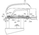
- the roof includes a connection part to which the support member supporting the communication antenna and the element are bolted
- the connecting portion includes a plurality of through holes for bolt connection and a plurality of rubber sleeves fitted into the through holes,
- the rubber sleeve has an upper flange portion and a lower flange portion, When the support and the element are bolted in the connecting portion, the upper flange portion is in close contact with the upper surface of the roof and the bottom surface of the support, and the lower flange portion is connected to the inner surface of the roof and the roof. Close to the top surface of the element.
- the upper flange portion of the rubber sleeve is in close contact with the upper surface of the roof and the bottom surface of the support, and the lower side of the rubber sleeve
- rain water, washing water, and the like are prevented from entering the interior of the cabin from each through hole of the connecting portion.
- the plurality of rubber sleeves having the upper and lower flange portions also serve as a waterproof member, it is possible to prevent water from entering the cabin while simplifying the configuration by reducing the number of parts.
- a cabin located on the rear side of the car body, And an electronic control system for automatic driving that automatically drives the vehicle body,
- the electronic control system includes an antenna unit for satellite navigation having an inertial measurement device therein,
- the work vehicle is attached to the left and right central portions of the upper surface of the front portion of the cabin roof so that the antenna unit is positioned at the center of the wheel base at the center of the tread in the vehicle body.
- the antenna unit is attached to the upper surface of the roof of the cabin, the reception sensitivity of the radio wave from the satellite by the antenna unit is increased. Further, since the mounting position of the inertial measurement device is determined by the mounting position of the antenna unit as described above, it is not necessary to obtain the displacement amount of the inertial measurement device from the center of gravity position of the vehicle body in accordance with the position adjustment of the inertial measurement device. . Moreover, there is no possibility that the attachment position of the inertial measurement device is easily changed by a user or the like.
- the inertial measurement device is arranged at the center of the wheel base at the center of the tread in the vehicle body, so that the attachment position of the inertial measurement device is close to the center of gravity of the vehicle body at least in plan view.
- the calculation for correcting the yaw angle measured by the inertial measurement device based on the positional deviation amount of the inertial measurement device is simplified, so that the measurement result of the inertial measurement device can be corrected quickly and correctly. it can. That is, it is possible to quickly and accurately measure the yaw angle of the vehicle body by the inertial measurement device.
- the position and orientation of the vehicle body is measured using the global navigation satellite system
- the position deviation amount of the antenna unit can be quickly and accurately obtained from the yaw angle, pitch angle, roll angle, etc. of the vehicle body measured by the inertial measurement device.
- the positioning error caused by the positional deviation of the antenna unit included in the position and orientation of the vehicle body measured using the global navigation satellite system is based on the positional deviation amount of the antenna unit obtained from the measurement result of the inertial measurement device. Therefore, the correction for removing this positioning error from the measurement result can be performed quickly and appropriately.
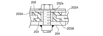
- the roof includes a connecting portion to which the antenna unit is bolted
- the connecting portion includes a plurality of through holes for bolt connection and a plurality of rubber sleeves fitted into the through holes,
- the rubber sleeve includes a flange portion
- the flange portion of the rubber sleeve is located between the top surface of the roof and the bottom surface of the antenna unit, so that vibration on the vehicle body side is not caused by the antenna. Difficult to get to the unit
- the flange portion of the rubber sleeve is in close contact with the top surface of the roof and the bottom surface of the antenna unit, so that rain water, washing water, and the like are prevented from entering the cabin through the through holes of the connecting portion.
- the antenna unit can be supported in an anti-vibration manner while simplifying the configuration, and water can enter the cabin. Can be prevented.
- the upper surface of the front portion of the roof is formed to be front-lowering
- a pedestal for attaching the antenna unit is formed to bulge upward at the left and right central portions of the front portion of the roof.
- the seat surface of the pedestal to which the antenna unit is attached is formed on a horizontal surface suitable for mounting the antenna unit different from the front upper surface of the roof while the drainage around the antenna unit is improved. be able to.
- the installation posture of the antenna unit can be made appropriate while preventing rainwater, washing water, etc. from staying around the antenna unit and adversely affecting the antenna unit.
- the front upper surface of the roof to which the antenna unit is attached is formed so as to be lowered downward, it is lower than the rear upper surface of the roof, so that the antenna unit is more than the case where the antenna unit is attached to the rear upper surface of the roof.
- the vehicle height including the unit is lowered. Thereby, it becomes easy to take in and out the work vehicle from the entrance to the barn or the like in which the work vehicle is stored.
- drainage grooves are formed on the upper surface of the roof from the mounting position of the antenna unit to the left and right ends of the front edge of the roof.
- rain water, washing water, etc. that has fallen around the antenna unit can easily flow from the periphery of the antenna unit toward the left and right ends of the roof front edge along the draining groove. And rain water, washing water, etc. which reached the left and right ends of the roof front edge flow downward from the left and right ends of the roof front edge.
- the electronic control system includes an external display unit that displays the driving status of the vehicle body during automatic driving so that the driving status can be viewed from the outside.
- the external display unit includes left and right indicator lamps arranged on both left and right sides of the vehicle body, and an external display control unit configured to control the operation of the indicator light according to the driving state of the vehicle body during automatic operation.
- the whole of the indicator lights should not protrude upward from the upper end of the vehicle body. Even if it is arranged, the manager who is outside the work vehicle during automatic driving can easily visually recognize the operating state of either the left or right indicator lamp. And by this visual recognition, the administrator can easily grasp the driving situation of the vehicle body in the work vehicle during automatic driving.
- the indicator lamp includes a laminated display lamp in which a plurality of display units having different display colors are laminated,
- the stacked indicator lamp is disposed on both left and right sides of the vehicle body in a vertically long posture in which the plurality of display portions are arranged in the vertical direction.
- the operating state of the indicator lamp can be changed but also the operating indicator can be changed according to the driving state of the vehicle body during automatic driving. This makes it possible for the manager outside the vehicle to easily grasp the driving situation of more vehicle bodies in the work vehicle being automatically driven.
- each display unit can be provided in the vehicle body in a state where it can be easily seen from the outside of the work vehicle.
- a cabin that forms a boarding space is mounted on the vehicle body,
- the laminated indicator lamp is disposed on the lateral outer sides of the left and right rear pillars in the cabin.
- an administrator outside the vehicle can visually recognize the operating state of either the left or right stacked indicator lamp without being obstructed by the cabin. That is, it is possible to make it possible for the manager outside the vehicle to easily grasp the driving state of the vehicle body in the work vehicle that is being automatically driven by operating the left and right stacked indicator lamps while having the cabin.
- the laminated indicator lamp is disposed at a position inside the vehicle body from the lateral outer ends of the left and right traveling apparatuses and at a position below the vehicle body from the roof of the cabin.
- the left and right stacked indicator lamps are arranged at positions within the lateral width of the vehicle body within the longitudinal length of the vehicle body below the cabin roof.
- the left and right stacked indicator lamps are placed on the laterally outer sides of the left and right rear pillars that are easily visible to the manager outside the vehicle, but the left and right stacked indicator lamps are It is possible to avoid the possibility of contact with the like.
- the cabin includes a support member that supports a combination lamp having a brake lamp and a blinker lamp,
- the laminated indicator lamp is supported by the support member so as to be positioned laterally outside the combination lamp.
- the left and right stacked indicator lamps can be suitably disposed on the lateral outer sides of the left and right rear pillars that are easily visible to the manager outside the vehicle, while simplifying the configuration by sharing the parts.
- the indicator lamp comprises a blinker lamp
- the external display control unit is configured to control the operation of the winker lamp according to the driving state of the vehicle body during automatic driving.
- the left and right turn signal lamps that do not need to be operated particularly during traveling in the field as an indicator light that allows a manager or the like outside the vehicle to grasp the driving state of the vehicle body during automatic driving.
- the left and right turn signal lamps are originally arranged at positions that are easily visible to people outside the vehicle, the operating state of the turn signal lamps can be easily recognized by an administrator outside the vehicle. In other words, it is possible to allow an administrator outside the vehicle to grasp the driving state of the vehicle body in the work vehicle during automatic driving while simplifying the configuration by sharing the parts.
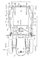
- the left view of the tractor by 1st Embodiment (following and FIG. 8 is the same).
- the top view of a tractor. The block diagram which shows schematic structure of a control system.
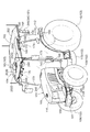
- the perspective view of the cabin upper part which shows the shape etc. of a roof.
- the perspective view of the principal part which shows the frame structure of a cabin, the support structure of a ground plane, etc.
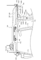
- the longitudinal cross-sectional rear view of the principal part which shows the shape of a roof, the attachment structure of a ground plane, etc.
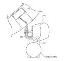
- the longitudinal side view of the principal part which shows the attachment structure of a communication antenna and a ground plane.
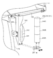
- the longitudinal left side view of the principal part which shows the shape of the principal part in a roof, the attachment structure of an antenna unit, etc.
- FIG. 25 is a left side view of the tractor according to the second embodiment (hereinafter the same as in FIG. 24), and shows the arrangement of the indicator lamps and the like.
- the top view of the tractor which shows arrangement
- the perspective view of a tractor which shows arrangement
- the longitudinal cross-sectional left view of the principal part which shows the structure of a tractor front-end part.
- the perspective view of the principal part which shows the structure of a tractor front-end part.
- the block diagram which shows schematic structure of a control system.
- the front view of the cabin upper part which shows arrangement
- the rear view of the cabin upper part which shows arrangement
- the left view of the cabin upper part which shows arrangement
- the perspective view of the principal part which shows the frame structure of a cabin.
- the disassembled perspective view of the principal part which shows the support structure of an indicator lamp.
- the cross-sectional top view of the principal part which shows the support structure of an indicator lamp.
- the perspective view of the principal part which shows the connection structure of an antenna unit.
- the longitudinal left side view of the principal part which shows the connection structure of an antenna unit.
- the longitudinal left side view of the principal part which shows the vibration proof structure of an antenna unit.
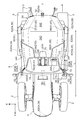
- the direction indicated by the arrow F shown in FIG. 1 is the front side of the tractor, and the direction indicated by the arrow U is the upper side of the tractor. 2 is the front side of the tractor, and the direction indicated by the arrow R is the right side of the tractor.
- a tractor an example of a work vehicle
- a tractor includes a body frame 1 that extends over both front and rear ends of a vehicle body, left and right front wheels 2 that function as drivable steering wheels, and drive wheels.
- Left and right rear wheels 3 that function, a driving unit 4 disposed on the front side of the body frame 1, a cabin 6 that forms a riding space and a driving unit 5 on the rear side of the body frame 1, and the rear of the body frame 1
- the tractor includes an engine 8 disposed in the prime mover 4, a pedal-operated main clutch 9 that interrupts power from the engine 8, and power that passes through the main clutch 9 for traveling and working. And a left and right side brakes (not shown) acting on the left and right rear wheels 3, and the like.
- the engine 8 is an electronically controlled diesel engine equipped with a common rail system.
- the three-point link mechanism 7 is driven to swing in the vertical direction by the operation of an electrohydraulic control type lifting / lowering drive unit 10 provided in the vehicle body.
- the three-point link mechanism 7 is connected to working devices such as a rotary tiller, a plow, a disk harrow, a cultivator, a subsoiler, a seeding device, and a spraying device.
- working devices such as a rotary tiller, a plow, a disk harrow, a cultivator, a subsoiler, a seeding device, and a spraying device.
- the working device connected to the three-point link mechanism 7 is a drive type such as a rotary tiller, the working power extracted from the rear part of the vehicle body is transmitted to the working device via an external transmission shaft or the like.
- the driving unit 5 includes a steering wheel 11 for manual steering that enables manual steering of the left and right front wheels 2, a main transmission lever 12, an auxiliary transmission lever 13, and a forward / reverse switching switch.
- a driver's seat 17 and the like are provided together with various human operation tools such as left and right brake pedals (not shown) that enable operation of the left and right side brakes.
- the steering wheel 11 is linked to the left and right front wheels 2 via a fully hydraulic power steering unit (hereinafter referred to as PS unit) 18 or the like.
- PS unit fully hydraulic power steering unit
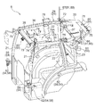
- the cabin 6 includes left and right front pillars 21, left and right center pillars 22, left and right rear pillars 23, a roof 24 supported by each pillar 21 to 23, and the cabin 6.
- the front panel 25 that forms the front surface
- the left and right door panels 26 that are supported by the left and right center pillars 22 so as to be openable and swingable
- the left and right side panels 27 that form the rear side surface of the cabin 6, and the rear surface of the cabin 6 are formed.
- a rear panel 28 is provided.
- the roof 24 is attached to a roof frame 29 connected to each pillar 21 to 23, a rear cover 30 extending rearward from the roof frame 29, and a lower portion of the roof frame 29.
- an inner space 34 is formed between the rear cover 30 and the inner roof 31 and the outer roof 32.
- the internal space 34 accommodates an air conditioning unit (not shown) that enables air conditioning in the boarding space, a radio (not shown), and the like.
- the roof frame 29 includes a front beam 35 extending from the left and right front pillars 21, left and right side beams 36 extending from one of the left and right front pillars 21 to the rear pillar 23, and a rear beam 37 extending from the left and right rear pillars 23. It is formed in a rectangular shape.
- the left and right front pillars 21 are arranged on the front side of the vehicle body relative to the center portion of the wheel base L in the vehicle body.
- the left and right front pillars 21 are positioned on the left and right center side of the vehicle body as the upper side of the upper half is viewed from the front, and the upper half is positioned on the front and rear center side of the vehicle body as viewed from the side.
- the part is curved.
- the left and right center pillars 22 are curved so that the upper side is located on the left and right center side of the vehicle body in the front view, and the upper side is located on the front and rear center side of the vehicle body in the side view.
- the left and right rear pillars 23 are positioned so that the upper side in the front view is positioned closer to the left and right central sides of the vehicle body, and the left and right rear pillars 23 are curved in a substantially vertical posture in the side view.
- Each of the panels 25 to 28 is a curved panel made of glass or a transparent acrylic resin that is curved along the corresponding pillars 21 to 23.
- the front-rear width and the left-right width of the roof frame 29 can be narrowed to the extent that they are not damaged. As a result, it is possible to improve the stability of the vehicle body by reducing the size and weight of the upper part of the cabin without reducing the operability and comfort in the boarding space.
- the vehicle body includes a main electronic control unit (hereinafter referred to as a main ECU) including a travel control unit 40A that performs control related to the travel of the vehicle body, a work control unit 40B that performs control related to the work device, and the like. 40) is mounted.
- the main ECU 40 includes the above-described electrohydraulic control type lift drive unit 10, an engine electronic control unit (not shown), an electronically controlled main transmission 41, an electronically controlled forward / reverse switching device 42, and an electronically controlled type.
- the electronic control unit such as the main ECU 40 includes a microprocessor having a CPU and an EEPROM.
- the traveling control unit 40A has various control programs that enable control related to traveling of the vehicle body.
- the work control unit 40B has various control programs that enable control related to the work device.
- the main transmission 41, the forward / reverse switching device 42, and the PTO clutch 43 include a sub-transmission device (not shown) that shifts the driving power in a stepped manner, and a PTO that shifts the working power in a stepped manner.
- a transmission device (not shown) and the like are provided in the transmission unit.
- the main transmission 41 employs a hydrostatic continuously variable transmission that changes the driving power continuously.
- the forward / reverse switching device 42 also serves as a traveling clutch that interrupts the traveling power.
- the in-vehicle information acquisition unit 45 includes various switches such as the above-described lift switch, turning lift switch, reverse lift switch, and PTO switch, a rotation sensor that detects the output rotational speed of the engine 8, and a subtransmission device.
- a vehicle speed sensor for detecting the output speed of the vehicle as a vehicle speed
- a main transmission sensor for detecting the operation position of the main transmission lever 12
- an auxiliary transmission sensor for detecting the operation position of the auxiliary transmission lever 13
- a shuttle for detecting the operation position of the shuttle lever 14.
- a height sensor that detects the vertical swing angle of left and right lift arms (not shown) in the lift drive unit 10 as a height position of the working device, and a front wheel
- Various sensors such as a steering angle sensor for detecting two steering angles are included.
- the traveling control unit 40A determines the vehicle speed, the engine speed, the operation position of the main transmission lever 12, and the auxiliary transmission lever.
- Vehicle speed control for operating a trunnion shaft (not shown) of the main transmission 41 is performed so that the control target vehicle speed obtained from the 13 operation positions is reached.
- the driver can change the vehicle speed to an arbitrary speed by operating the main transmission lever 12 to an arbitrary operation position.
- the traveling control unit 40A performs forward / reverse switching control for switching the forward / reverse switching device 42 to a transmission state corresponding to the operation position of the shuttle lever 14 based on the output of the shuttle sensor.
- the driver can set the traveling direction of the vehicle body to the forward direction by operating the shuttle lever 14 to the forward position.
- the driver can set the traveling direction of the vehicle body to the reverse direction by operating the shuttle lever 14 to the reverse position.
- the work control unit 40B controls the operation of the lift drive unit 10 based on the output of the lift sensor and the output of the height sensor so that the work device is positioned at a height position corresponding to the operation position of the lift lever 15. Perform position control. Thereby, the driver
- the work control unit 40B sets the work device to the preset upper limit position based on the lift command from the lift switch and the output of the height sensor. Ascending control is performed to control the operation of the elevating drive unit 10 so as to ascend. Thus, the driver can automatically raise the work device to the upper limit position by switching the elevation switch to the elevation command state.
- the work control unit 40B moves the lifting device to the lifting lever based on the lowering command from the lifting switch, the output of the lifting sensor, and the output of the height sensor.
- the lowering control is performed to control the operation of the lifting drive unit 10 so as to be lowered to the work height position set by 15. Accordingly, the driver can automatically lower the work device to the work height position by switching the lift switch to the lowering command state.
- the work control unit 40B determines that the steering angle of the front wheel 2 is reduced based on the output of the steering angle sensor that detects the steering angle of the front wheel 2 when execution of the turning interlocking increase control is selected by manual operation of the turning lift switch. When it is detected that the set angle for turning is reached, the above-described ascent control is automatically performed. As a result, the driver can automatically raise the work device to the upper limit position in conjunction with the start of the coasting turn by selecting the execution of the turn interlocking raising control.
- the work control unit 40B detects the manual operation to the reverse position of the shuttle lever 14 based on the output of the shuttle sensor.
- the above-described ascent control is automatically performed. Accordingly, the driver can automatically raise the work device to the upper limit position in conjunction with the switching to the reverse traveling by selecting the execution of the reverse interlocking rising control.
- the work control unit 40B When the operation position of the PTO switch is switched to the on position by manual operation of the PTO switch, the work control unit 40B is configured so that the working power is transmitted to the work device based on the switching to the on position. Clutch engagement control for switching 43 to the engagement state is performed. Thereby, the driver
- the work control unit 40B When the operation position of the PTO switch is switched to the cut position by manual operation of the PTO switch, the work control unit 40B prevents the work power from being transmitted to the work device based on the switch to the cut position. Clutch disengagement control is performed to switch to disengaged state. Thereby, the driver
- the work control unit 40B automatically performs the above-described clutch disengagement control in conjunction with the execution of the above-described ascent control.
- the clutch engagement control described above is automatically performed in conjunction with the execution of the lowering control.
- the driver can stop the working device in conjunction with the automatic raising of the working device to the upper limit position by operating the PTO switch to the automatic position.
- the working device can be operated in conjunction with the automatic lowering to the position.
- the tractor includes a selection switch 50 that enables selection of an operation mode and an electronic control system 51 for automatic operation that enables automatic operation of the vehicle body. Further, this tractor has a manual operation mode, an automatic operation mode, and a cooperative operation mode as operation modes.
- the electronic control system 51 includes the main ECU 40, an automatic steering unit 52 that enables automatic steering of the left and right front wheels 2, a positioning unit 53 that measures the position and orientation of the vehicle body, and a monitoring unit 54 that monitors the surroundings of the vehicle body. , Etc.
- the automatic steering unit 52 includes the PS unit 18 described above.
- the PS unit 18 steers the left and right front wheels 2 based on the turning operation of the steering wheel 11 when the manual operation mode is selected. Further, when the automatic operation mode or the cooperative operation mode is selected, the PS unit 18 steers the left and right front wheels 2 based on a control command from the main ECU 40.
- the left and right front wheels 2 can be automatically steered without providing a steering unit dedicated to automatic steering. Further, when a problem occurs in the electric system of the PS unit 18, it can be easily switched to manual steering by the passenger, and the vehicle body can be continuously operated.
- the positioning unit 53 uses the well-known GPS (Global Positioning System), which is an example of the Global Navigation Satellite System (GNSS), A satellite navigation device 55 for measuring the direction is provided.
- GPS Global Positioning System
- GNSS Global Navigation Satellite System
- DGPS Direct GPS
- RTK-GPS Real Time Kinematic GPS
- the satellite navigation device 55 includes an antenna unit 56 for satellite navigation that receives radio waves transmitted from GPS satellites (not shown) and positioning data transmitted from reference stations (not shown) installed at known positions. I have.
- the reference station transmits positioning data obtained by receiving radio waves from GPS satellites to the satellite navigation device 55.
- the satellite navigation device 55 obtains the position and orientation of the vehicle body based on positioning data obtained by receiving radio waves from GPS satellites and positioning data from a reference station.
- the antenna unit 56 is attached to the roof 24 of the cabin 6 located at the top of the vehicle body so that the reception sensitivity of radio waves from GPS satellites is increased. Therefore, the position and orientation of the vehicle body measured using GPS include a positioning error due to the positional deviation of the antenna unit 56 due to the yawing, pitching, or rolling of the vehicle body.
- the vehicle body has a three-axis gyroscope (not shown) and a three-direction acceleration sensor (not shown) in order to enable correction for removing the positioning error, and the yaw angle of the vehicle body Inertial measurement unit (IMU) 57 that measures pitch angle, roll angle, and the like is provided.
- the inertial measurement device 57 is provided inside the antenna unit 56 in order to easily obtain the above-described positional deviation amount of the antenna unit 56.
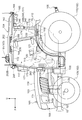
- the antenna unit 56 is attached to the left and right central portions of the upper surface of the front portion of the roof 24 of the cabin 6 so as to be positioned at the central portion of the wheel base L at the central portion of the tread T in the vehicle body in plan view (see FIG. 2). ).
- the attachment position of the inertial measurement device 57 is close to the position of the center of gravity of the vehicle body at least in plan view.
- the calculation for correcting the yaw angle or the like measured by the inertial measurement device 57 based on the positional deviation amount of the inertial measurement device 57 from the center of gravity position of the vehicle body is simplified.
- the result can be corrected quickly and correctly. That is, measurement of the yaw angle of the vehicle body by the inertial measurement device 57 can be performed quickly and accurately.
- the satellite navigation device 55 measures the position and orientation of the vehicle body
- the antenna unit 56 is displaced due to yawing, pitching, or rolling of the vehicle body
- the positional deviation amount 56 can be quickly and accurately obtained from the yaw angle, pitch angle, roll angle, etc. of the vehicle body measured by the inertial measurement device 57.
- the positioning error caused by the positional deviation of the antenna unit 56 included in the position and orientation of the vehicle body measured by the satellite navigation device 55 is based on the positional deviation amount of the antenna unit 56 obtained from the measurement result of the inertial measurement device 57. It is possible to obtain the information quickly and accurately, and to correct the positioning error from the measurement result of the satellite navigation device 55 quickly and appropriately.
- the main ECU 40 includes an automatic driving control unit 40C having various control programs that enable automatic driving of the vehicle body.
- the automatic driving control unit 40C performs automatic driving control for automatically driving the vehicle body when the automatic driving mode or the cooperative driving mode is selected by an artificial operation of the selection switch 50.
- the automatic driving control unit 40C sets the target driving route and the positioning so that the vehicle body properly operates while automatically driving the preset target driving route of the field at the set speed. Based on the positioning results of the unit 53, various control commands are transmitted to the travel control unit 40A, the work control unit 40B, and the like at appropriate timing.
- the traveling control unit 40A appropriately applies various control commands to the main transmission 41, the forward / reverse switching device 42, and the like based on various control commands from the automatic driving control unit 40C and various information acquired by the in-vehicle information acquisition unit 45.
- the transmission of the main transmission 41 and the forward / reverse switching device 42 are controlled by transmitting at a proper timing.
- the work control unit 40B sends various control commands to the elevating drive unit 10, the PTO clutch 43, and the like at appropriate timings based on various control commands from the automatic operation control unit 40C and various pieces of acquisition information of the in-vehicle information acquisition unit 45. To control the operation of the elevating drive unit 10 and the PTO clutch 43.
- the target travel route may be data based on the measurement result of the positioning unit 53 and the like, the travel route traveled during the work travel by manual operation on the field, the coasting turning start point, and the like. Further, the target travel route may be a data obtained from the travel route traveled at the time of teaching travel by manual operation on the field, the coasting start point, and the like based on the positioning result of the positioning unit 53 and the like. .
- the monitoring unit 54 includes an obstacle detection module 58 that detects the approach of an obstacle within a close distance (for example, within 1 m) to the vehicle body, and a short distance (for example, within 10 m) to the vehicle body.
- a close distance for example, within 1 m
- a short distance for example, within 10 m
- Three laser scanners 59 before and after detecting the approach of an obstacle a contact avoidance control unit 40D for performing contact avoidance control for avoiding contact with an obstacle
- four surveillance cameras 60 for photographing the periphery of the vehicle body
- a surveillance camera 60 Includes an image processing device 61 for processing an image taken by the camera.
- the obstacle detection module 58 includes eight sonars 62 for searching for obstacles within a short distance to the vehicle body, and the vehicle body based on the search information from each sonar 62.
- Two exploration information processing devices 63 that perform a determination process as to whether or not an obstacle has approached within a close range are provided.
- the eight sonars 62 are arranged in a distributed manner at the front end portion and the left and right end portions of the vehicle body so that the front and both left and right sides of the vehicle body are search target regions.
- Each sonar 62 transmits the search information obtained by the search to the corresponding search information processing device 63.
- Each exploration information processing device 63 determines whether or not an obstacle has approached within the closest distance to the vehicle body based on the time from transmission to reception of ultrasonic waves in each corresponding sonar 62, and the determination result. Is output to the contact avoidance control unit 40D.
- the obstacle detection module 58 detects the approach of the obstacle. Further, since the sonar 62 is not provided at the rear end portion of the vehicle body, the obstacle detection module 58 is prevented from erroneously detecting a work device attached to the rear portion of the vehicle body so as to be movable up and down as an obstacle. Yes.
- the obstacle detection module 58 is configured such that, for example, when the vehicle body is traveling toward the heel by automatic driving, or when the vehicle body is traveling along the heel by automatic driving, When an abnormal approach is made within a close distance to, this wrinkle is detected as an obstacle. Further, when the moving body abnormally approaches within a close distance to the vehicle body, the moving body is detected as an obstacle.
- each laser scanner 59 includes a detection unit that detects an obstacle with a maximum detection angle of about 270 degrees, a processing unit that processes detection information from the detection unit, and the like. ing.
- the detection unit receives the reflected light by irradiating the detection target region with the laser beam.
- the processing unit determines whether an obstacle is approaching at a short distance from the vehicle body based on the time from laser beam irradiation to light reception, and outputs the determination result to the contact avoidance control unit 40D.
- the left and right laser scanners 59 on the front side the front of the vehicle body and the left and right sides are set as detection target areas.
- the rear single laser scanner 59 the rear of the vehicle body is set as the detection target area.
- the contact avoidance control unit 40 ⁇ / b> D has a control program that enables execution of contact avoidance control, and is provided in the main ECU 40.
- the contact avoidance control unit 40D prioritizes the control operation of the automatic operation control unit 40C when confirming the approach of the obstacle at a short distance to the vehicle body based on the determination result of each laser scanner 59. 59 and the contact avoidance control described above are performed based on the discrimination results of the search information processing devices 63.
- the contact avoidance control part 40D avoids a possibility that a vehicle body may contact an obstruction by performing contact avoidance control.
- the contact avoidance control unit 40D ends the contact avoidance control when it is confirmed that there is no obstacle within a short distance from the vehicle body based on the determination result of each laser scanner 59 during the execution of the contact avoidance control. At the same time, the automatic operation based on the control operation of the automatic operation control unit 40C is resumed.
- FIGS. 1 to 5 a wide-angle CCD camera for visible light is adopted for each monitoring camera 60.
- FIG. The surveillance cameras 60 are distributed and arranged at the front, rear, left and right ends of the roof 24 of the cabin 6 in order to capture the surroundings of the vehicle body without omission.
- the image processing device 61 processes the video signal from each surveillance camera 60, and the vehicle body front image, the vehicle body right image, the vehicle body left image, the vehicle body rear image, and the bird's-eye view image as seen from directly above the vehicle body. , Etc. are generated and transmitted to the display unit 64 of the boarding space.
- the display unit 64 includes a control unit 64B that switches an image or the like displayed on the liquid crystal panel 64A based on an artificial operation of various operation switches (not shown) displayed on the liquid crystal panel 64A. .
- the driver in the manual operation mode, the driver can easily view the surroundings and working conditions of the vehicle during driving by displaying an image from the image processing device 61 on the liquid crystal panel 64A. .
- the manager displays the image from the image processing device 61 on the liquid crystal panel 64A, so that the vehicle body during the automatic driving or the cooperative driving is displayed. It is possible to easily see the surrounding situation and the working situation.
- the manager visually recognizes an abnormality in the vicinity of the vehicle body or in the work situation during the automatic driving or the cooperative driving, the manager can promptly perform appropriate measures according to the type and degree of the abnormality.
- the electronic control system 51 includes a communication module 65 that wirelessly communicates various types of information with other vehicles, and cooperative operation control that performs cooperative operation control based on information from other vehicles.
- An operation control unit 40E is provided.
- the cooperative operation control unit 40E includes a control program that enables execution of cooperative operation control and the like, and is provided in the main ECU 40.
- the automatic operation control unit 40C is configured so that the vehicle body appropriately performs a work while automatically traveling at a set speed on a preset target travel route for parallel operation. Based on the travel route and the positioning result of the positioning unit 53, various control commands are transmitted to the travel control unit 40A, the work control unit 40B, and the like at appropriate timing.
- the cooperative driving control unit 40E performs an inter-vehicle distance determination process and an inter-vehicle distance optimization process in the cooperative driving control.
- the cooperative operation control unit 40E includes a target travel route for parallel running of the own vehicle, a positioning result of the positioning unit 53, a target travel route for parallel running of other vehicles, and position information of other vehicles, etc. Based on the above, it is determined whether the inter-vehicle distance in the traveling direction of the preceding other vehicle and the own vehicle, the inter-vehicle distance in the parallel running direction of the preceding other vehicle and the own vehicle, and the like are appropriate. Then, when any inter-vehicle distance is not appropriate, the inter-vehicle distance optimization process is performed in preference to the control operation of the automatic operation control unit 40C so that the inter-vehicle distance is appropriate.
- the cooperative operation control unit 40E outputs a deceleration command to the travel control unit 40A when the inter-vehicle distance in the traveling direction is shorter than the appropriate distance, thereby controlling the travel control unit 40A.
- the main transmission 41 is decelerated to return the inter-vehicle distance in the traveling direction to an appropriate distance.
- the cooperative driving control unit 40E restarts the automatic driving based on the control operation of the automatic driving control unit 40C as the inter-vehicle distance in the traveling direction returns to the appropriate distance, thereby reducing the vehicle speed for normal driving. Increase the speed to the set speed and maintain the distance between the vehicles in the direction of travel.
- the cooperative operation control unit 40E outputs a speed increase command to the travel control unit 40A, whereby the main transmission 41 is controlled by the control operation of the travel control unit 40A.
- the cooperative driving control unit 40E restarts the automatic driving based on the control operation of the automatic driving control unit 40C as the inter-vehicle distance in the traveling direction returns to the appropriate distance, thereby reducing the vehicle speed for normal driving. Decrease to the set speed to maintain the distance between vehicles in the direction of travel.
- the cooperative operation control unit 40E outputs a steering command to the other vehicle side to the travel control unit 40A, thereby controlling the travel control unit 40A.
- the left and right front wheels 2 are steered to the other vehicle side, and the inter-vehicle distance in the parallel running direction is returned to an appropriate distance.
- the cooperative driving control unit 40E normally sets the traveling direction of the vehicle body by resuming the automatic driving based on the control operation of the automatic driving control unit 40C as the inter-vehicle distance in the parallel running direction returns to the appropriate distance. Return to the traveling direction for traveling and maintain the inter-vehicle distance in the parallel traveling direction at an appropriate distance.
- the cooperative operation control unit 40E When the inter-vehicle distance in the parallel running direction is shorter than the appropriate distance, the cooperative operation control unit 40E outputs a steering command to the travel control unit 40A to the side away from the other vehicle, thereby controlling the travel control unit 40A.
- the cooperative driving control unit 40E normally sets the traveling direction of the vehicle body by resuming the automatic driving based on the control operation of the automatic driving control unit 40C as the inter-vehicle distance in the parallel running direction returns to the appropriate distance. Return to the traveling direction for traveling and maintain the inter-vehicle distance in the parallel traveling direction at an appropriate distance.
- the host vehicle can automatically and appropriately run parallel to the preceding other vehicle while appropriately maintaining the inter-vehicle distance in the traveling direction and the inter-vehicle distance in the side-by-side direction.
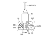
- the communication module 65 includes three communication antennas 66 to 68 having different frequency bands and a communication information processing device 69.
- Each of the communication antennas 66 to 68 is disposed at the upper end of the cabin 6 in order to increase communication sensitivity.
- the communication information processing device 69 is disposed in the internal space 34 of the roof 24 in order to improve waterproofness and dustproofness.
- the first communication antenna 66 having the highest frequency band wirelessly communicates image information with a large amount of information with the communication module 65 of another vehicle.
- the second communication antenna 67 having the next highest frequency band wirelessly communicates in-vehicle information such as vehicle speed excluding image information with the communication module 65 of another vehicle.
- the third communication antenna 68 having the lowest frequency band wirelessly communicates various information such as a work travel start command and a stop command with the remote controller 70.
- the first communication antenna 66 is attached to the left front end portion of the auxiliary frame 33 in the roof 24 via a first support tool 71.
- the second communication antenna 67 is attached to the right front end portion of the auxiliary frame 33 via the second support 72.
- the third communication antenna 68 is attached to the left front portion of the upper surface of the roof 24 via the third support tool 73.
- a radio receiving antenna 74 is attached to the upper end of the left front pillar 21 in the cabin 6.
- in-vehicle information acquisition unit 45, each laser scanner 59, image processing device 61, each search information processing device 63, and the like are communicable via main ECU 40 in communication information processing device 69. It is connected.
- in-vehicle information such as vehicle speed acquired by the in-vehicle information acquisition unit 45, monitoring information from each laser scanner 59 and each search information processing device 63, monitoring image information from the image processing device 61, etc.
- in-vehicle information can communicate well with other vehicles via the communication antennas 66 to 68, and can be shared with other vehicles traveling in a coordinated manner.
- vehicle speed adjustment linked with other vehicles that cooperate in traveling avoidance of contact with obstacles associated with other vehicles that cooperate in traveling, etc. Is easier to do. As a result, it is possible to more reliably avoid contact with other vehicles that run in cooperation.
- the contact avoidance control unit 40D starts the contact avoidance control
- a deceleration command is also output to the cooperative operation control unit 40E.
- the coordinated operation control unit 40E transmits this deceleration command to another vehicle via the communication module 65.
- the cooperative operation control unit 40E reads the vehicle speed detected by the vehicle speed sensor, and transmits the read vehicle speed to the other vehicle via the communication module 65.
- the contact avoidance control unit 40D When the obstacle detection module 58 detects the presence of an obstacle within a close distance to the vehicle body in the low speed traveling state based on the deceleration command, the contact avoidance control unit 40D performs the traveling control unit 40A and the work control unit 40B. In addition, an emergency stop command is output to the cooperative operation control unit 40E. The cooperative operation control unit 40E transmits this emergency stop command to the other vehicle via the communication module 65. Further, when each laser scanner 59 stops detecting an approach of an obstacle at a short distance from the vehicle body in the deceleration traveling state based on the deceleration command, the contact avoidance control unit 40D performs the cooperative operation in addition to the traveling control unit 40A. A speed increase command is also output to the control unit 40E.
- the coordinated operation control unit 40E transmits this speed increase command to the other vehicle via the communication module 65. Thereafter, in the speed increasing traveling state based on the speed increasing command, the cooperative operation control unit 40E reads the vehicle speed detected by the vehicle speed sensor, and transmits the read vehicle speed to the other vehicle via the communication module 65.
- the communication module 65 receives the deceleration command and the vehicle speed and outputs them to the cooperative operation control unit 40E. Then, the cooperative operation control unit 40E outputs the deceleration command and the vehicle speed to the traveling control unit 40A, and performs the deceleration control for reducing the vehicle speed from the normal traveling set speed to the vehicle speed of the other vehicle. Make it.
- the communication module 65 receives this emergency stop command and outputs it to the cooperative operation control unit 40E.
- the cooperative operation control unit 40E outputs the emergency stop command to the travel control unit 40A and the work control unit 40B, and the travel control unit 40A and the work control unit 40B cause the vehicle body and the work device to stop emergency stop. To do. Further, when the speed increase command and the vehicle speed of the other vehicle are transmitted from the other vehicle in the deceleration traveling state by the deceleration control, the communication module 65 receives the speed increase command and the vehicle speed and outputs them to the cooperative operation control unit 40E. . Then, the cooperative operation control unit 40E outputs the speed increase command and the vehicle speed to the travel control unit 40A, and causes the travel control unit 40A to increase the vehicle speed to the set speed for normal travel according to the speed increase of the other vehicle. Increase speed control.
- the cooperative operation control unit 40E of the succeeding vehicle receives the deceleration command from the preceding vehicle and the vehicle speed of the other vehicle by wireless communication of the communication module 65
- the received information is received.
- the vehicle speed of the following vehicle can be made the same as the vehicle speed of the preceding vehicle after deceleration by the deceleration control of the traveling control unit 40A based on this output information.
- the cooperative operation control unit 40E of the succeeding vehicle receives the speed increase command from the preceding vehicle and the vehicle speed of the other vehicle through the wireless communication of the communication module 65, these received information is sent to the own vehicle.
- the vehicle speed of the succeeding vehicle can be made the same as the vehicle speed of the preceding vehicle after the speed increase by the speed increase control of the travel control unit 40A based on this output information.
- the cooperative operation control unit 40E of the following vehicle receives an emergency stop command from the preceding vehicle through wireless communication of the communication module 65 in the coordinated low speed state, the received information is output to the traveling control unit 40A of the own vehicle. Then, by the emergency stop control of the travel control unit 40A and the work control unit 40B based on the output information, the subsequent vehicle can be emergency stopped in conjunction with the preceding vehicle.
- the preceding vehicle from colliding with an obstacle, and to avoid the possibility that the following vehicle collides with the preceding vehicle due to the emergency stop of the preceding vehicle.
- the communication module 65 receives this other vehicle information and outputs it to the cooperative operation control unit 40E. Then, the cooperative operation control unit 40E outputs other vehicle information to the display unit 64.
- the display unit 64 when an operation switch (not shown) for displaying other vehicle information displayed on the liquid crystal panel 64A is operated and display of other vehicle information is selected, the vehicle speed and surrounding image of the other vehicle are selected. Other vehicle information is displayed on the liquid crystal panel 64A.
- the operation information display for other vehicle information is operated by operating the operation switch for displaying other vehicle information in the preceding vehicle.
- the monitoring unit 54 includes six lighting lamps 75 that have a large number of LEDs and illuminate the shooting target portion of each monitoring camera 60.
- the monitoring unit 54 includes six lighting lamps 75 that have a large number of LEDs and illuminate the shooting target portion of each monitoring camera 60.
- the remote operation tool 70 includes a start switch 70 ⁇ / b> A that outputs a start command for work travel by automatic operation when manually operated, and stops work travel by automatic operation when manually operated.
- a stop switch 70B that outputs a command
- an information processing unit 70C that processes various information such as a start command and a stop command
- a communication antenna 70D that performs wireless communication with the third communication antenna 68
- a lamp or a buzzer An alarm 70E is provided.
- the automatic operation control unit 40C When the automatic operation control unit 40C receives a start command from the start switch 70A of the remote operation tool 70 via the communication module 65 while the vehicle body is stopped while the automatic operation mode or the cooperative operation mode is selected. Determines whether the contact avoidance control unit 40D is executing the contact avoidance control. When the contact avoidance control is being executed, the automatic operation control unit 40C transmits a notification command for notifying that the vehicle body cannot be started to the remote operation tool 70 via the communication module 65. To do. When the remote control tool 70 receives the notification command from the automatic operation control unit 40C, the information processing unit 70C activates the notification device 70E based on the notification command, and the vehicle body operation cannot be started. Inform the administrator. When the contact avoidance control is not being executed, the automatic operation control unit 40C sends various control commands related to the start of work travel to the travel control unit 40A, the work control unit 40B, and the like based on the start command. To start working on the car body.
- the automatic operation control unit 40C When the automatic operation control unit 40C receives a stop command from the stop switch 70B of the remote operation tool 70 via the communication module 65 during work travel by automatic driving of the vehicle body, the automatic operation control unit 40C performs work travel based on the stop command. Various control commands relating to the stop are transmitted to the travel control unit 40A, the work control unit 40B, and the like at an appropriate timing to urgently stop the work travel of the body.
- the manager when the manager starts the work traveling by the automatic driving of the vehicle body without boarding the vehicle body, the manager can board the vehicle body by operating the start switch 70A of the remote operation tool 70. It is possible to start work traveling by automatic driving of the vehicle body.
- the manager when the manager stops the work traveling by the automatic driving of the vehicle body without boarding the vehicle body, the manager operates the stop switch 70B of the remote operation tool 70, so that the vehicle body can be moved without boarding the vehicle body. Work travel by automatic operation can be stopped.
- a ground plane 76 (an example of an element) that enhances the communication capability of the third communication antenna is disposed below the third communication antenna 68.
- the ground plane 76 is accommodated in the internal space 34 of the roof 24.
- the third communication antenna 68 is disposed above the center of the ground plane 76.
- the radio gain of the third communication antenna 68 can be increased by the ground plane 76, and thus the size of the third communication antenna 68 can be reduced. And in order to improve the communication sensitivity of the 3rd communication antenna 68 by this size reduction, even if it attaches the 3rd communication antenna 68 to the upper surface of the roof 24 in the cabin 6, the vehicle body including the 3rd communication antenna 68 is included. Overall height can be kept low. Further, by storing the ground plane 76 in the inner space 34 of the roof 24, the third communication antenna 68 and the ground plane 76 are connected to the roof 24 of the cabin 6 as compared with the case where the ground plane 76 is provided outside the roof 24. Can be compactly equipped.
- the communication performance of the third communication antenna 68 can be improved while suppressing the overall height of the vehicle body including the third communication antenna 68 from being increased.
- the ground plane 76 is formed of a rectangular metal plate having a plane suitable for increasing the radio wave gain.
- the front end portion of the ground plane 76 is connected to the front beam 35 of the roof frame 29 in the roof 24 via a support plate 77.
- the right end portion of the ground plane 76 is connected to a support base 78 of the roof frame 29 that supports the antenna unit 56 via a connector 79.
- a support portion 76 ⁇ / b> A that supports the outer roof 32 of the roof 24 and the third support 73 for the third communication antenna is provided at the center of the ground plane 76.
- the ground plane 76 is connected to the front beam 35 of the roof frame 29 and supports the third communication antenna 68 via the outer roof 32 and the third support 73.
- the ground plane 76 can also be used as a support member that supports the outer roof 32 and the third communication antenna 68. As a result, it is possible to simplify the configuration by reducing the number of parts.
- the roof 24 has a first connection in which the third support 73 and the support portion 76 ⁇ / b> A of the ground plane 76 are bolted to the left front portion of the upper surface of the outer roof 32.
- 24A is provided.
- the first connecting portion 24A is formed with left and right first through holes 24a for bolt connection, and rubber sleeves 80 are fitted into the left and right first through holes 24a.
- Each rubber sleeve 80 is connected to the upper surface of the outer roof 32 and the bottom surface of the third support member 73 as the third support member 73 and the support portion 76A of the ground plane 76 are bolted to the first connection portion 24A.
- the upper flange portion 80A is in close contact with the inner surface of the outer roof 32 and the lower flange portion 80B is in close contact with the upper surface of the ground plane 76.
- the upper flange portion 80A of the rubber sleeve 80 is connected to the upper surface of the outer roof 32 and the third support member.
- the lower flange portion 80 ⁇ / b> B of the rubber sleeve 80 is in close contact with the inner surface of the outer roof 32 and the upper surface of the ground plane 76.
- left and right rubber sleeves 80 having the upper and lower flange portions 80A and 80B also serve as waterproof members, it is possible to prevent water from entering the cabin 6 while simplifying the configuration by reducing the number of parts.
- the left and right first through holes 24a in the first connecting portion 24A of the roof 24 are enlarged in diameter so that the lower side allows the lower flange portion 80B to enter.
- a spacer 81 that allows proper deformation of the rubber sleeve 80 at the time of bolt connection and restricts the bolt screwing amount is fitted together with the rubber sleeve 82. The bolt sleeve is prevented from loosening by the action of the rubber sleeve 80 and the spacer 81.
- the roof 24 of the cabin 6 has a second connecting portion 24 ⁇ / b> B for the antenna unit formed at the left and right center portions on the front side of the upper surface of the outer roof 32. Yes.
- the upper surface of the second connecting portion 24B is formed horizontally.
- Four second through holes 24b for bolt connection are formed in the second connecting portion 24B, and a rubber sleeve 82 is fitted in each second through hole 24b.
- Each rubber sleeve 82 has an upper flange portion 82 ⁇ / b> A that is in close contact with the upper surface of the outer roof 32 and the bottom surface of the antenna unit 56 as the antenna unit 56 is bolted to the second connecting portion 24 ⁇ / b> B.
- the upper flange portion 82 ⁇ / b> A of the rubber sleeve 82 is positioned between the upper surface of the outer roof 32 and the bottom surface of the antenna unit 56. This makes it difficult for the vibration on the vehicle body side to be transmitted to the antenna unit 56. Then, the upper flange portion 82A of the rubber sleeve 82 is in close contact with the upper surface of the outer roof 32 and the bottom surface of the antenna unit 56, so that rainwater, washing water, etc. can pass through the second through holes 24b of the second connecting portion 24B from the cabin. 6 is prevented from entering the inside.
- the antenna unit 56 can be supported in a vibration-proof manner while simplifying the configuration by reducing the number of parts. In addition, it is possible to prevent water from entering the cabin 6.
- the second connecting portion 24 ⁇ / b> B of the outer roof 32 also serves as a connecting portion that is bolted to the support base 78 of the roof frame 29. That is, the antenna unit 56 is coupled together with the support base 78 together with the outer roof 32. Thereby, the improvement of the assembly
- each rubber sleeve 82 has a lower flange that comes into close contact with the upper surface of the support table 78 and the inner surface of the outer roof 32 as the outer roof 32 and the antenna unit 56 are bolted to the support table 78. It has a part 82B.
- Each second through hole 24b in the second connecting portion 24B of the roof 24 is expanded in diameter so that the lower surface side allows the lower flange portion 82B to enter.
- a spacer 83 that allows proper deformation of the rubber sleeve 82 during bolt connection and limits the amount of bolt screwing is fitted in each second through hole 24b together with the rubber sleeve 82.
- the roof 24 is formed on a first inclined surface 24 ⁇ / b> D in which the upper surface on the front side of the outer roof 32 that is the periphery of the antenna unit 56 is inclined downward.
- the roof 24 is formed on a second inclined surface 24 ⁇ / b> E whose upper surface on the rear side of the outer roof 32 is inclined downward.
- the roof 24 includes left and right bulging edge portions 24 ⁇ / b> F that bulge upward at the left and right ends of the outer roof 32, having a longitudinal length extending across the front and rear ends of the roof 24.
- the roof 24 is provided with a draining groove 24G on the upper surface on the front side of the outer roof 32 to guide the water on the roof toward the left and right bulging edges 24F so that the water on the roof bypasses the antenna unit 56. Yes.
- the draining groove 24G has a first groove part 24Ga facing left and right across the left and right bulging edges 24F at a position higher than the antenna unit 56 on the first inclined surface 24D, and a roof from the left and right ends of the first groove part 24Ga. 24, left and right second groove portions 24Gb crossing the left and right bulging edge portions 24F toward both left and right end portions of the front end edge.
- the roof 24 is located on the upper side of the left and right center side in the surface area on the left and right center side located between the left and right bulging edges 24 ⁇ / b> F on the upper surface of the outer roof 32. It is formed so as to be curved. As a result, it is possible to make it more difficult for rain water, washing water, and the like that have fallen on the upper surface of the roof 24 to flow toward the antenna unit 56 located at the left and right center of the roof 24. As a result, it is possible to more effectively avoid the possibility that rainwater, washing water, or the like may adversely affect the antenna unit 56 and may enter the roof from the location where the antenna unit 56 is attached.
- the roof 24 has a concave portion 24 ⁇ / b> H for connecting a connector to the antenna unit 56 at a higher position on the first inclined surface 24 ⁇ / b> D adjacent to the antenna unit 56.
- the first inclined surface 24 ⁇ / b> D is formed around the antenna unit 56 in the roof 24, and the pedestal for mounting the antenna unit is inflated on the top surface of the roof 24, while the water drainage around the antenna unit 56 is good.
- the connector 84 can be easily connected to the antenna unit 56 without being formed.
- the roof 24 positions and guides the cable 85 connected to the antenna unit 56 and the cable 86 connected to the third communication antenna 68 below the roof 24.
- Left and right guide grooves 24K are provided.
- the left and right guide grooves 24K include a first guide portion 24Ka formed on the first inclined surface 24D and a second guide portion 24Kb formed on the left and right bulging edge portions 24F.
- the cable 85 for the antenna unit and the cable 86 for the third communication antenna do not protrude upward from the upper surface of the roof 24, and the roof is viewed from the upper surface side of the roof 24 along the left and right guide grooves 24 ⁇ / b> K. 24 can be routed downward. Thereby, it is possible to avoid the possibility that the antenna unit cable 85 and the third communication antenna cable 86 are lifted from the upper surface of the roof 24 and caught by other objects.
- left and right press plates 87 for preventing the cables 85 and 86 from lifting from the guide grooves 24K are detachably provided on the upper surface of the roof 24 and caught by other objects.
- the draining groove 24G is formed deeper than the connector connecting recess 24H and the cable guiding groove 24K in order to improve the water guiding ability.
- the draining groove 24G is connected to the left and right guide grooves 24K on the left and right ends of the first groove 24Ga, so that the left and right center side of the first groove 24Ga is also used as a cable guide groove.
- the work vehicle may be configured in a semi-crawler specification including left and right crawlers instead of the left and right rear wheels 3.
- the work vehicle may be configured in a full crawler specification including left and right crawlers instead of the left and right front wheels 2 and the left and right rear wheels 3.
- the work vehicle may be configured to have an electric specification including an electric motor instead of the engine 8.
- the work vehicle may be configured in a hybrid specification including the engine 8 and an electric motor.
- the working vehicle may not have one or both of the manual driving mode and the cooperative driving mode.
- the roof 24 of the cabin 6 may have a configuration in which the inner space 34 is formed between the inner roof 31 and the outer roof 32 without including the rear cover 30.
- the roof 24 of the cabin 6 may be configured such that the entire upper surface thereof is inclined forwardly or downwardly.
- the antenna unit 56 may be provided on the rear side of the roof 24 inclined downward and the upper surface of the roof 24 around the antenna unit may be a second inclined surface 24E inclined downward. In this configuration, by forming the drain groove 24G on the second inclined surface 24E, it is possible to avoid the possibility that rainwater, washing water, or the like adversely affects the antenna unit 56.
- the draining groove 24G is provided only between the left and right bulging edges 24F so that the water on the roof that has received the guiding action is directed to the left and right bulging edges 24F while bypassing the antenna unit 56. It may be formed.
- the element (ground plane) 76 may employ a metal mesh instead of the metal plate, or may employ a plurality of metal bars that radiate from the lower part of the third communication antenna 68. Good.
- the rubber sleeve 80 is configured so that the third support 73 and the support portion 76A of the element (ground plane) 76 are bolt-connected to the first connection portion 24A of the roof 24 and the upper surface of the outer roof 32 and the first support portion 76A. Only the upper flange portion 80 ⁇ / b> A that is in close contact with the bottom surface of the three support tool 73 may be provided.
- the present invention can be applied to other than the tractor exemplified in the above embodiment. That is, the present invention can also be applied to other work vehicles such as a rice transplanter, a combiner, and a mower having an electronic control system for automatic driving that automatically drives the vehicle body and a cabin that forms a boarding space.
- work vehicles such as a rice transplanter, a combiner, and a mower having an electronic control system for automatic driving that automatically drives the vehicle body and a cabin that forms a boarding space.
- the tractor exemplified in the present embodiment includes a body frame 101 extending over both front and rear ends of the vehicle body, left and right traveling devices 102 arranged on the left and right of the vehicle body frame 101, and a front portion of the vehicle body frame 101.
- a driving unit 103 disposed on the side, a cabin 104 disposed on the rear side of the vehicle body frame 101, and a three-point link mechanism 105 for connecting the work device, which is attached to the rear end of the vehicle body frame 101 so as to be movable up and down. , Etc.
- the vehicle body frame 101 includes a front frame 107 that extends from the lower part of the engine 106 disposed in the driving unit 103 to the vehicle body front side, and a vehicle body rear side from the lower rear end of the engine 106.
- a case unit 108 that also serves as a rear frame, and the like. Although illustration is omitted, inside the case unit 108 is a pedal-operated main clutch that interrupts the power from the engine 106, and a speed change transmission that shifts the power via the main clutch for traveling and working.
- the unit and left and right side brakes that act on the left and right traveling devices 102 are provided.
- the left and right traveling devices 102 include left and right front wheels 109 that function as steerable wheels and left and right rear wheels 110 that function as drive wheels.
- the left and right front wheels 109 are supported in a steerable state at both left and right ends of a wheel support member 111 supported on the front frame 107 so as to be able to roll.
- the wheel support member 111 is a front axle case that includes a transmission shaft 111A for driving front wheels and the like.
- the left and right rear wheels 110 are drivably supported by the case unit 108, and the upper side of each rear wheel 110 is covered with left and right rear fenders 112 disposed on the rear side of the vehicle body.
- the driving unit 103 is a water-cooled engine 106 disposed on the vehicle body rear side of the driving unit 103 on the lower side in the cooling direction of the driving unit 103, and a cooling fan disposed on the vehicle body front side on the upper side in the cooling direction than the engine 106 113, a radiator 114 disposed on the front side of the vehicle with respect to the cooling fan 113, a battery 115 disposed on the front side of the vehicle with respect to the radiator 114, an exhaust treatment device (not shown) disposed on the rear of the engine 106, and the engine 106 An air cleaner (not shown) disposed above the front portion, a swingable bonnet 116 that covers the engine 106, the radiator 114, and the like from above are provided.
- the engine 106 an electronically controlled diesel engine equipped with a common rail system is employed.
- the exhaust treatment apparatus includes DOC ((Diesel Oxidation Catalyst) and DPF (Dieseliesparticulate filter) inside.
- the cabin 104 forms a driving section 117 and a boarding space on the rear side of the vehicle body.
- the driving unit 117 includes a clutch pedal 118 that enables operation of the main clutch, left and right brake pedals 149 that allow operation of the left and right side brakes, and steering for manual steering that enables manual steering of the left and right front wheels 109.
- a wheel 119, a shuttle lever 120 for forward / reverse switching, a driver seat 122 having an armrest 121 for the right arm, a display unit 123 having a touch-operable liquid crystal panel 123A, and the like are provided.
- the steering wheel 119 is linked to the left and right front wheels 109 via a steering mechanism 125 having a fully hydraulic power steering unit 124.
- the armrest 121 is provided with a main transmission lever 126, an elevating lever 127 for setting the height position of the working device, and an elevating switch 128 for instructing raising / lowering of the working device.
- the three-point link mechanism 105 is driven to swing in the vertical direction by the operation of an electrohydraulic control type lifting / lowering drive unit 129 provided in the vehicle body.
- the three-point link mechanism 105 can be connected to working devices such as a rotary tiller, a plow, a disk harrow, a cultivator, a subsoiler, a seeding device, and a spraying device. If the working device connected to the three-point link mechanism 105 is a rotary tiller driven by power from the vehicle body, the working power extracted from the transmission unit is transmitted via the external transmission shaft. Is done.
- a main electronic control unit 130 including a travel control unit 130A that performs control related to travel of the vehicle body, a work control unit 130B that performs control related to the work device, and the like is mounted on the vehicle body.
- the main ECU 130 includes an electrohydraulic control type lifting drive unit 129, an engine electronic control unit (hereinafter referred to as an engine ECU) 131, an electronic control main transmission 132 provided in the transmission transmission unit, and a forward / backward travel.
- the switching device 133, the PTO clutch 134, the electrohydraulic brake operation unit 135 that enables automatic operation of the left and right side brakes, the in-vehicle information acquisition unit 136 that acquires in-vehicle information including the vehicle speed, and the like are connected to the CAN (Controller Area). It is communicably connected via an in-vehicle LAN (Local Area Network) such as Network) or a communication line.
- the main ECU 130 and the engine ECU 131 include a microprocessor having a CPU (Central Processing Unit), an EEPROM (Electrically® Erasable Programmable Read-Only Memory), and the like.
- the traveling control unit 130A has various control programs that enable control related to traveling of the vehicle body.
- the work control unit 130B includes various control programs that enable control related to the work device.
- the main transmission 132 employs a hydrostatic continuously variable transmission that continuously changes the driving power.
- the forward / reverse switching device 133 also serves as a traveling clutch that interrupts the traveling power.
- the transmission unit includes a main transmission 132 and the like, a sub-transmission that shifts driving power in stages, a PTO transmission that shifts working power in stages, and the like. Is provided.
- the in-vehicle information acquisition unit 136 includes a rotation sensor 137 for detecting the output rotation speed of the engine 106, a vehicle speed sensor 138 for detecting the output rotation speed of the auxiliary transmission as a vehicle speed, and a first lever for detecting the operation position of the main transmission lever 126.
- the sensor 139, the second lever sensor 141 for detecting the operation position of the auxiliary transmission lever 140 provided in the driving unit 117, the third lever sensor 142 for detecting the operation position of the shuttle lever 120, and the operation position of the elevating lever 127 are detected.
- the travel control unit 130 ⁇ / b> A determines the vehicle speed based on the output of the rotation sensor 137, the output of the vehicle speed sensor 138, the output of the first lever sensor 139, and the output of the second lever sensor 141.
- Vehicle speed control is performed to operate a trunnion shaft (not shown) of the main transmission 132 so that the control target vehicle speed obtained from the operation position and the operation position of the auxiliary transmission lever 140 is reached.
- the driver can change the vehicle speed to an arbitrary speed by operating the main transmission lever 126 to an arbitrary operation position.
- the traveling control unit 130 ⁇ / b> A performs forward / reverse switching control for switching the forward / reverse switching device 133 to a transmission state corresponding to the operation position of the shuttle lever 120 based on the output of the third lever sensor 142.
- the driver can set the traveling direction of the vehicle body to the forward direction by operating the shuttle lever 120 to the forward position.
- the driver can set the traveling direction of the vehicle body to the reverse direction by operating the shuttle lever 120 to the reverse position.
- the work control unit 130 ⁇ / b> B sets the lifting drive unit 129 so that the work device is positioned at a height position corresponding to the operation position of the lifting lever 127. Perform position control to control operation. Accordingly, the driver can change the height position of the work device to an arbitrary height position by operating the elevating lever 127 to an arbitrary operation position.
- the work control unit 130B sets the work device in advance based on the lift command from the lift switch 128 and the output of the height sensor 147. Ascending control for controlling the operation of the elevating drive unit 129 is performed so as to ascend to the upper limit position. Thus, the driver can automatically raise the work device to the upper limit position by switching the elevation switch 128 to the elevation command state.
- the work control unit 130 ⁇ / b> B is based on the lowering command from the lifting switch 128, the output of the fourth lever sensor 143, and the output of the height sensor 147.
- the lowering control is performed to control the operation of the lifting drive unit 129 so that the working device is lowered to the working height position set by the lifting lever 127.
- the driver can automatically lower the work device to the work height position by switching the lift switch 128 to the lowering command state.
- the work control unit 130B determines that the steering angle of the front wheel 109 is based on the output of the steering angle sensor 148 that detects the steering angle of the front wheel 109 when execution of turning interlocking increase control is selected by manual operation of the turning lift switch 144.
- the above-described ascent control is automatically performed.
- the driver can automatically raise the work device to the upper limit position in conjunction with the start of the coasting turn by selecting the execution of the turn interlocking raising control.
- the work control unit 130B detects manual operation to the reverse position of the shuttle lever 120 based on the output of the third lever sensor 142 when execution of reverse interlocking increase control is selected by manual operation of the reverse advance switch 145. When this happens, the above-described ascent control is automatically performed. Accordingly, the driver can automatically raise the work device to the upper limit position in conjunction with the switching to the reverse traveling by selecting the execution of the reverse interlocking rising control.
- the work control unit 130B When the operation position of the PTO switch 146 is switched to the on position by manual operation of the PTO switch 146, the work control unit 130B is configured so that the working power is transmitted to the work device based on the switching to the on position. Clutch engagement control is performed to switch the clutch 134 to the engaged state. Thus, the driver can operate the work device by operating the PTO switch 146 to the on position.
- the work control unit 130B prevents the working power from being transmitted to the work device based on the switching to the cutting position. Clutch disengagement control for switching 134 to disengagement is performed. Thus, the driver can stop the working device by operating the PTO switch 146 to the cut position.
- the work control unit 130B automatically performs the above-described clutch disengagement control in conjunction with the execution of the above-described ascent control,
- the aforementioned clutch engagement control is automatically performed in conjunction with the aforementioned lowering control.
- the driver can stop the working device in conjunction with the automatic raising of the working device to the upper limit position by operating the PTO switch 146 to the automatic position.
- the work device can be operated in conjunction with the automatic lowering to the vertical position.
- this tractor includes a selection switch 150 that enables selection of a manual operation mode, an automatic operation mode, and the like of the operation mode, and a vehicle body when the automatic operation mode is selected.
- an electronic control system 151 for automatic operation includes the main ECU 130, the automatic steering unit 152 that enables automatic steering of the left and right front wheels 109, a positioning unit 153 that measures the position and orientation of the vehicle body, and a monitoring unit 154 that monitors the surroundings of the vehicle body. , Etc.
- the automatic steering unit 152 is constituted by the power steering unit 124 described above.
- the power steering unit 124 steers the left and right front wheels 109 based on the turning operation of the steering wheel 119 when the manual operation mode is selected. Further, when the automatic driving mode is selected, the power steering unit 124 steers the left and right front wheels 109 based on a control command from the main ECU 130.
- the left and right front wheels 109 can be automatically steered without a dedicated steering unit for automatic steering.
- the electric system of the power steering unit 124 it is possible to easily switch to manual steering by the occupant and to continue driving the vehicle body.
- the positioning unit 153 uses a well-known GPS (Global Positioning System) that is an example of a Global Navigation Satellite System (GNSS).
- GPS Global Positioning System
- GNSS Global Navigation Satellite System
- a satellite navigation device 160 that measures the position and orientation of the vehicle body is provided.
- DGPS Different GPS
- RTK-GPS Real Time Kinematic GPS
- RTK-GPS suitable for positioning of a moving body is adopted. .
- the satellite navigation device 160 includes an antenna unit 161 for satellite navigation that receives radio waves transmitted from GPS satellites (not shown) and positioning data transmitted from a reference station (not shown) installed at a known position. I have.
- the reference station transmits positioning data obtained by receiving radio waves from GPS satellites to the satellite navigation device 160.
- the satellite navigation device 160 obtains the position and orientation of the vehicle body based on positioning data obtained by receiving radio waves from GPS satellites and positioning data from a reference station.
- the antenna unit 161 is attached to the roof 162 of the cabin 104 located at the top of the vehicle body so that the reception sensitivity of the radio wave from the GPS satellite is increased. Therefore, the position and orientation of the vehicle body measured using GPS include a positioning error due to the positional deviation of the antenna unit 161 due to the yawing, pitching, or rolling of the vehicle body.
- the vehicle body has a three-axis gyroscope (not shown) and a three-direction acceleration sensor (not shown) in order to enable correction for removing the positioning error, and the yaw angle of the vehicle body Inertial measurement unit (IMU) 63 that measures pitch angle, roll angle, and the like is provided.
- IMU Inertial measurement unit
- the inertial measurement device 163 is provided inside the antenna unit 161 in order to make it easy to obtain the positional deviation amount of the antenna unit 161 described above.
- the antenna unit 161 is attached to the left and right center portions of the upper surface of the front portion of the roof 162 of the cabin 104 so as to be positioned at the center portion of the wheel base L at the center portion of the tread T in the vehicle body in plan view (see FIG. 10). ).
- the attachment position of the inertial measurement device 163 is close to the center of gravity of the vehicle body.
- the calculation for correcting the yaw angle or the like measured by the inertial measurement device 163 based on the positional deviation amount of the inertial measurement device 163 from the center of gravity position of the vehicle body is simplified, and therefore the measurement by the inertial measurement device 163 is simplified.
- the result can be corrected quickly and correctly. That is, measurement of the yaw angle of the vehicle body by the inertial measurement device 163 can be performed quickly and accurately.
- the satellite navigation device 160 measures the position and orientation of the vehicle body, if the position shift occurs in the antenna unit 161 due to yawing, pitching, or rolling of the vehicle body, the antenna unit at this time 161 can be quickly and accurately obtained from the yaw angle, pitch angle, roll angle, etc. of the vehicle body measured by the inertial measurement device 163.
- the positioning error caused by the positional deviation of the antenna unit 161 included in the position and orientation of the vehicle body measured by the satellite navigation device 160 is based on the positional deviation amount of the antenna unit 161 obtained from the measurement result of the inertial measurement device 163. It can be obtained quickly and accurately, and correction for removing this positioning error from the measurement result of the satellite navigation device 160 can be performed quickly and appropriately.
- the main ECU 130 includes an automatic operation control unit 130 ⁇ / b> C having various control programs that enable automatic operation of the vehicle body.
- the automatic operation control unit 130 ⁇ / b> C travels based on the target travel route and the positioning result of the positioning unit 153 so that the vehicle body automatically travels while properly performing the target travel route of the field set in advance at the set speed.
- Various control commands are transmitted to the control unit 130A, the work control unit 130B, and the like at appropriate timing.
- the traveling control unit 130A appropriately applies various control commands to the main transmission 132, the forward / reverse switching device 133, and the like based on various control commands from the automatic driving control unit 130C and various information acquired by the in-vehicle information acquisition unit 136.
- the transmission of the main transmission device 132, the forward / reverse switching device 133, and the like are controlled by transmitting at a proper timing.
- the work control unit 130B sends various control commands to the elevating drive unit 129, the PTO clutch 134, and the like at appropriate timings based on various control commands from the automatic operation control unit 130C and various types of acquisition information of the in-vehicle information acquisition unit 136. To control the operation of the lift drive unit 129, the PTO clutch 134, and the like.
- the target travel route may be data based on the positioning result of the positioning unit 153, such as the travel route traveled during the work travel by manual operation on the field and the coasting turning start point.
- the target travel route may be a data obtained based on the positioning result of the positioning unit 153, such as the travel route traveled during teaching travel by manual operation on the field and the coasting turning start point. .
- the monitoring unit 154 includes an obstacle detection module 164 that detects the presence or absence of an obstacle within a close distance (for example, within 1 m) with respect to the vehicle body, and a short distance to the vehicle body.
- the obstacle detection module 164 includes eight obstacle searchers (to be described later) that search for obstacles within a short distance from the vehicle body, and obstacles within a short distance from the vehicle body based on search information from each obstacle searcher. And two search information processing devices 169 that determine whether or not the two have approached each other.
- Each obstacle probe employs a sonar 168 that uses ultrasonic waves for distance measurement as an example of a distance measurement sensor.
- the eight sonars 168 are arranged in a distributed manner at the front end portion and the left and right end portions of the vehicle body so that the front side and both the left and right sides of the vehicle body are search target regions.
- Each sonar 168 transmits the search information obtained by the search to the corresponding search information processing apparatus 169.
- Each exploration information processing device 169 determines whether or not an obstacle has approached within a close distance to the vehicle body based on the time from transmission to reception of ultrasonic waves in each corresponding sonar 168. Is output to the contact avoidance control unit 130D.
- the obstacle detection module 164 detects the approach of the obstacle. Further, since the sonar 168 is not provided at the rear end portion of the vehicle body, the obstacle detection module 164 is prevented from erroneously detecting a work device attached to the rear portion of the vehicle body so as to be movable up and down as an obstacle. Yes.
- the obstacle detection module 164 for example, when the vehicle body is traveling toward the kite by automatic driving, or when the vehicle is traveling along the kite at the shore by automatic driving, When an abnormal approach is made within a close distance to, this wrinkle is detected as an obstacle. Further, when the moving body abnormally approaches within a close distance to the vehicle body, the moving body is detected as an obstacle.
- Each obstacle detector employs a laser scanner 165 having a detection angle of about 270 degrees.
- Each laser scanner 165 includes a detection unit 165A that detects an obstacle and a processing unit 165B that processes detection information from the detection unit 165A.
- the detection unit 165A receives the reflected light by irradiating the detection target region with a laser beam.
- the processing unit 165B determines whether or not an obstacle is approaching at a short distance from the vehicle body based on the time from laser beam irradiation to light reception, and outputs the determination result to the contact avoidance control unit 130D.
- the front laser scanner 165 the area on the front side of the vehicle body is set as the detection target area.
- the rear laser scanner 165 an area on the rear side of the vehicle body is set as a detection target area.
- the contact avoidance control unit 130D includes a control program that enables execution of contact avoidance control, and is provided in the main ECU 130.
- the contact avoidance control unit 130D prioritizes the automatic operation based on the control operation of the automatic operation control unit 130C when confirming the approach of the obstacle at a short distance to the vehicle body based on the determination result of each laser scanner 165. Start contact avoidance control. Then, the contact avoidance control unit 130D performs contact avoidance control based on the determination results of the laser scanners 165 and the search information processing apparatuses 169.
- the contact avoidance control unit 130D outputs a deceleration command to the travel control unit 130A when the contact avoidance control is started.
- the contact avoidance control unit 130D decelerates the main transmission 132 by the control operation of the travel control unit 130A, and reduces the vehicle speed from the set speed for normal travel to the set speed for contact avoidance.
- the contact avoidance control unit 130D confirms that the obstacle is approaching within the closest distance to the vehicle body based on the determination result of one of the search information processing devices 169, and the traveling control unit 130A and An emergency stop command is output to the work control unit 130B.
- the contact avoidance control unit 130D switches the forward / reverse switching device 133 to the neutral state by the control operation of the traveling control unit 130A, and operates the left and right brakes by the operation of the brake operation unit 135 and the left and right front wheels 109.
- the rear wheel 110 is braked.
- the contact avoidance control unit 130D switches the PTO clutch 134 to the disengaged state by the operation of the work control unit 130B and stops the operation of the work device.
- the contact avoidance control unit 130D When the contact avoidance control unit 130D confirms that there is no obstacle within a short distance from the vehicle body based on the determination result of each laser scanner 165 in the low speed traveling state, the contact avoidance control unit 130D instructs the traveling control unit 130A to increase the speed. Is output, and then the contact avoidance control is terminated. Thereby, the contact avoidance control unit 130D increases the speed of the main transmission 132 by the control operation of the travel control unit 130A to increase the vehicle speed from the contact avoidance set speed to the normal travel set speed. The automatic operation based on the control operation of the automatic operation control unit 130C is resumed.
- a wide-angle CCD camera for visible light is adopted for each monitoring camera 166.
- One of the six monitoring cameras 166 is for photographing the front of the vehicle body, and this monitoring camera 166 is in a tilted posture in which the photographing direction is directed forward and downward, and at the left and right central locations of the front end at the upper end of the cabin 104. Is installed.
- Two of the six monitoring cameras 166 are for right-side shooting of the vehicle body, and these monitoring cameras 166 are tilted so that the shooting direction is directed downward to the right, and are positioned at the right end portion of the upper end portion of the cabin 104. It is installed at a predetermined interval in the front and rear.
- Two of the six monitoring cameras 166 are for left-side shooting of the vehicle body, and these monitoring cameras 166 are inclined at the left end position in the upper end portion of the cabin 104 in an inclined posture in which the shooting direction is directed to the lower left. It is installed at a predetermined interval in the front and rear.
- One of the six monitoring cameras 166 is for rearward shooting of the vehicle body, and this monitoring camera 166 is in a tilted posture in which the shooting direction is rearward and downward, and the left and right center of the rear end at the upper end of the cabin 104. It is installed at the location. As a result, it is possible to capture the surroundings of the vehicle body without omission.
- the right monitoring camera 166 and the left monitoring camera 166 may be provided one by one and installed at appropriate locations on both the left and right sides of the upper end portion of the cabin 104.
- the image processing device 167 processes the video signal from each surveillance camera 166, and displays a vehicle body front image, a vehicle body right side image, a vehicle body left side image, a vehicle body rear image, and a bird's-eye view image looking down from directly above the vehicle body. , Etc. are generated and transmitted to the display unit 123 or the like.
- the display unit 123 includes a control unit 123B that switches an image displayed on the liquid crystal panel 123A based on an artificial operation of various operation switches (not shown) displayed on the liquid crystal panel 123A.
- the driver can easily view the surroundings and working conditions of the vehicle during driving by displaying an image from the image processing device 167 on the liquid crystal panel 123A. .
- the driver can easily drive a good vehicle body according to the type of work.
- the manager can easily display the image from the image processing device 167 on the liquid crystal panel 123A, so that the surrounding situation and the working situation of the vehicle during the automatic driving can be easily performed. Can be visually recognized.
- the manager can promptly take appropriate measures according to the type and degree of the abnormality.
- the electronic control system 151 includes a cooperative control unit 170 that automatically moves the vehicle body in cooperation with another vehicle of the same specification when the cooperative operation mode is selected by an artificial operation of the selection switch 150.
- the cooperative control unit 170 includes a communication module 171 that wirelessly communicates information related to cooperative traveling with another vehicle including vehicle position information, and cooperative driving that performs cooperative driving control based on information from the other vehicle.
- a control unit 130E includes a control program that enables execution of cooperative operation control, and is provided in the main ECU 130.
- the automatic operation control unit 130C causes the vehicle to travel automatically while performing a proper operation on the preset target travel route for parallel running at a set speed.
- various control commands are transmitted to the travel control unit 130A and the work control unit 130B at appropriate timing.
- the coordinated operation control unit 130E uses the target traveling route for the parallel running of the own vehicle, the positioning result of the positioning unit 153, the target traveling route for the concurrent running of the other vehicle, the position information of the other vehicle, etc. It is determined whether or not the inter-vehicle distance in the traveling direction of the vehicle and the own vehicle, the inter-vehicle distance in the parallel running direction of the preceding other vehicle and the own vehicle, and the like are appropriate. If any of the inter-vehicle distances is not appropriate, the cooperative operation control is started in preference to the automatic operation based on the control operation of the automatic operation control unit 130C so that the inter-vehicle distance is appropriate.
- the cooperative driving control unit 130E outputs a deceleration command to the traveling control unit 130A when the inter-vehicle distance in the traveling direction is shorter than the appropriate distance. Thereby, cooperative driving control unit 130E decelerates main transmission 132 by the control operation of traveling control unit 130A, and returns the inter-vehicle distance in the traveling direction to an appropriate distance. Then, the cooperative driving control unit 130E restarts the automatic driving based on the control operation of the automatic driving control unit 130C as the inter-vehicle distance in the traveling direction returns to the appropriate distance, thereby reducing the vehicle speed for normal driving. Increase the speed to the set speed and maintain the distance between the vehicles in the direction of travel.
- the cooperative driving control unit 130E When the inter-vehicle distance in the traveling direction is longer than the appropriate distance, the cooperative driving control unit 130E outputs a speed increase command to the traveling control unit 130A. Thereby, the cooperative operation control unit 130E causes the main transmission 132 to perform a speed-up operation by the control operation of the traveling control unit 130A, and returns the inter-vehicle distance in the traveling direction to an appropriate distance. Then, the cooperative driving control unit 130E restarts the automatic driving based on the control operation of the automatic driving control unit 130C as the inter-vehicle distance in the traveling direction returns to the appropriate distance, thereby reducing the vehicle speed for normal driving. Decrease to the set speed to maintain the distance between vehicles in the direction of travel.
- the cooperative driving control unit 130E When the inter-vehicle distance in the parallel running direction is longer than the appropriate distance, the cooperative driving control unit 130E outputs a steering command to the other vehicle side to the traveling control unit 130A. Thereby, the cooperative driving control unit 130E steers the left and right front wheels 109 to the other vehicle side by the control operation of the traveling control unit 130A, and returns the inter-vehicle distance in the parallel traveling direction to an appropriate distance. Then, the cooperative driving control unit 130E normally sets the traveling direction of the vehicle body by resuming the automatic driving based on the control operation of the automatic driving control unit 130C as the inter-vehicle distance in the parallel running direction returns to the appropriate distance. Return to the traveling direction for traveling and maintain the inter-vehicle distance in the parallel traveling direction at an appropriate distance.
- the cooperative operation control unit 130E When the inter-vehicle distance in the parallel running direction is shorter than the appropriate distance, the cooperative operation control unit 130E outputs a steering command to the travel control unit 130A to the side away from the other vehicle. Thereby, the cooperative driving control unit 130E steers the left and right front wheels 109 away from the other vehicle by the control operation of the traveling control unit 130A, and returns the inter-vehicle distance in the parallel traveling direction to an appropriate distance. Then, the cooperative driving control unit 130E normally sets the traveling direction of the vehicle body by resuming the automatic driving based on the control operation of the automatic driving control unit 130C as the inter-vehicle distance in the parallel running direction returns to the appropriate distance.
- the host vehicle can automatically and appropriately run in parallel with the preceding other vehicle while maintaining the inter-vehicle distance in the traveling direction and the inter-vehicle distance in the side-by-side direction corrected.
- the cabin 104 includes a roof frame 172 that supports the roof 162 and the like, left and right front pillars 173 that support the front end of the roof frame 172, and a roof frame.
- the left and right center pillars 174 that support the front and rear intermediate portions of the 172, the left and right rear pillars 175 that support the rear side of the roof frame 172, the front panel 176 that forms the front surface of the cabin 104, and the left and right center pillars 174 are swingable.
- the left and right door panels 177 are supported, the left and right side panels 178 that form the rear side surface of the cabin 104, and the rear panel 179 that is supported by the roof frame 172 so as to be openable and swingable.
- the roof frame 172 includes a front beam 198 extending from the left and right front pillars 173, left and right side beams 199 extending from one of the left and right front pillars 173 and the rear pillar 175, and a rear beam 200 extending from the left and right rear pillars 175. It is formed in a rectangular shape.
- the left and right front pillars 173 are arranged on the front side of the vehicle body from the center of the wheel base L in the vehicle body.
- the left and right front pillars 173 are positioned so that the upper side of the upper half in the front view is positioned on the left and right center side of the vehicle body, and the upper side of the upper half in the side view is positioned on the front and rear center side of the vehicle body.
- the part is curved.
- the left and right center pillars 174 and the left and right rear pillars 175 are disposed between the left and right rear fenders 112 and the roof frame 172 disposed on the left and right sides of the driver seat 122.
- the left and right center pillars 174 are curved so that the upper side in the front view is positioned closer to the left and right central side of the vehicle body, and the upper side in the side view is positioned closer to the front and rear center side of the vehicle body.
- the left and right rear pillars 175 are positioned such that the upper side in the front view is positioned closer to the left and right center side of the vehicle body, and the left and right rear pillars 175 are bent in a substantially vertical posture in the side view.
- Each panel 176 to 179 employs a curved panel made of glass or transparent acrylic resin that is curved along the corresponding pillars 173 to 175.
- the front-rear width and the left-right width of the roof frame 172 can be reduced as long as they are not damaged. As a result, it is possible to improve the stability of the vehicle body by reducing the size and weight of the upper part of the cabin without reducing the operability and comfort in the boarding space.
- the cabin 104 includes an auxiliary frame 190 extending rearward from the upper ends of the left and right rear pillars 175.
- the auxiliary frame 190 supports a rear laser scanner 165, a rear-viewing monitoring camera 166, and the like.
- the cabin 104 includes left and right combination lamps 240 at the front end portion and the rear end portion, respectively.
- Each combination lamp 240 includes a brake lamp 241 and a blinker lamp 242 (an example of an indicator lamp).
- the left and right combination lamps 240 on the front side are attached to the upper and lower central portions of the left and right front pillars 173.
- the left and right combination lamps 240 are supported by left and right support members 244 supported in a suspended posture by the auxiliary frame 190 of the cabin 104 and either the left or right rear pillar 175.
- the electronic control system 151 includes an external display unit 245 that displays the driving state of the vehicle body during automatic driving so as to be visible from the outside.
- the external display unit 245 includes left and right stacked indicator lamps 246 (an example of indicator lamps) in which three display portions 246A to 246C having different display colors are stacked, and stacked displays according to the driving situation of the vehicle body during automatic operation.
- an external display control unit 130F for controlling the operation of the lamp 246.
- the external display control unit 130F is provided in the main ECU 130 with a control program that enables operation control of each stacked indicator lamp 246 in accordance with the driving state of the vehicle body during automatic driving.
- Each stacked indicator lamp 246 has a vertically long posture in which the display portions 246A to 246C are arranged in the vertical direction, on the laterally outer side of the left and right rear pillars 175 in the cabin 104, on the inner side of the lateral side of the left and right rear wheels 110,
- the cabin 104 is disposed at a position below the vehicle body with respect to the roof 162.
- the manager outside the tractor during automatic operation can arrange the stacked indicator lamps 246 so that they do not protrude from the upper end and the lateral width of the vehicle body. Can be visually recognized without being obstructed by the cabin 104. By this visual recognition, the administrator can easily grasp the driving state of the vehicle body in the tractor during automatic driving.
- the operation status of the vehicle body in the automatic tractor can be easily grasped by the manager outside the vehicle by the operation of the left and right stacked indicator lamps 246.
- the external display control unit 130F monitors the driving state of the vehicle body during automatic driving, the reception state of GPS signals, and the like. Then, the operation of the three display units 246A to 246C in each stacked indicator lamp 246 is controlled according to the driving state of the vehicle body during automatic driving, the reception state of the GPS signal, and the like. For example, if the vehicle body is traveling by automatic driving, the green display portion 246A among the three display portions 246A to 246C is turned on. If the vehicle body is temporarily stopped by automatic driving, the yellow display portion 246B among the three display portions 246A to 246C is turned on. If the vehicle body is in an emergency stop by automatic driving, the red display portion 246C among the three display portions 246A to 246C is turned on. If the reception of the GPS signal is unstable, the red display portion 246C is blinked.
- each stacked indicator lamp 246 is supported by left and right support members 244 via L-shaped metal fittings 247 so as to be positioned laterally outside the combination lamp 240.
- the stacked indicator lamp 246 is placed laterally outside the left and right rear pillars 175 in a state that does not hinder the visibility of the combination lamp 240 from the front or rear of the vehicle body.
- the left and right stacked indicator lamps 246 can be suitably arranged on the lateral outer sides of the left and right rear pillars 175 that are easily visible to the manager outside the vehicle, while simplifying the configuration by sharing the parts.
- the external display control unit 130F controls the operation of the left and right turn signal lamps 242 in accordance with the driving state of the vehicle body during automatic driving.
- the external display control unit 130F is configured to determine the traveling direction of the vehicle body based on the positioning information of the satellite navigation device 160 and the in-vehicle information from the in-vehicle information acquisition unit 136 during the work traveling by the automatic driving in the field.
- the distance from the current position to the starting point of the coasting turn is determined during straight traveling. If the distance to the coasting turning start point is longer than 15 m, the left and right turn signal lamps 242 are flashed every time the vehicle body moves 10 m.
- the blinker lamp 242 corresponding to the turning direction is blinked at a first set time period (for example, 1 second period). If the distance to the coasting turning start point is 5 to 10 m, the blinker lamp 242 corresponding to the turning direction is blinked at the second set time period (for example, 500 msec period). If the distance to the coasting turning start point is 0 to 5 m, the blinker lamp 242 corresponding to the turning direction is blinked at the third set time period (for example, 250 msec period). During turning, the turn signal lamp 242 in the turning direction is turned on. In addition, while the vehicle is moving backward, the left and right turn signal lamps 242 are blinked at the second set time period regardless of whether the vehicle is traveling straight or turning.
- the left and right turn signal lamps 242 that do not need to be operated particularly during traveling in the field as an indicator lamp that allows an administrator or the like outside the vehicle to grasp the driving state of the vehicle body during automatic driving. it can. Since the left and right turn signal lamps 242 are originally arranged at positions that are easily visible to people outside the vehicle, the operating state of each turn signal lamp 242 can be easily recognized by a manager outside the vehicle. That is, it is possible to allow an administrator or the like outside the vehicle to grasp the driving state of more vehicle bodies in the tractor during automatic driving while simplifying the configuration by sharing parts.
- the cabin 104 is provided with left and right work lights 248 at each of the front and rear end portions of the upper end portion thereof.
- the automatic operation control unit 130C Based on the detection of the illuminance sensor 249 that detects the illuminance outside the vehicle, the automatic operation control unit 130C automatically lights each work light 248 when detecting that the illuminance outside the vehicle has decreased below the set value. It is configured to perform automatic lighting control for automatically turning off each work lamp 248 when it is detected that the illuminance of the lamp exceeds the set value.
- the communication module 171 is configured to be capable of wireless communication with the remote control 250 for remote operation.
- the remote controller 250 includes a work light switch 250 ⁇ / b> A that transmits a turn-on command signal for instructing to turn on each work light 248 and a turn-off command signal for instructing turning off each work light 248.
- the communication module 171 receives the turn-on command signal or the turn-off command signal from the remote controller 250, the communication module 171 outputs the received command signal to the automatic operation control unit 130C.
- the automatic operation control unit 130C Upon receiving the lighting command signal or the turn-off command signal, the automatic operation control unit 130C turns on or turns off each work lamp 248 in preference to the automatic lighting control.
- each work lamp 248 can be turned on without interrupting the traveling, and the tractor that travels working can be monitored well by automatic operation.
- the automatic operation control unit 130 ⁇ / b> C detects the stop of the engine 106 by communication with the engine ECU 131, the automatic operation control unit 130 ⁇ / b> C ignores the detection of the illuminance sensor 249 and the lighting command signal from the remote controller 250 and does not turn on each work lamp 248. It is configured as follows. As a result, it is possible to prevent the battery from running out due to the lighting of each work light 248 that is not required when the engine is stopped.
- the automatic operation control unit 130C controls the operation of each work lamp 248 based on a first control mode for controlling the operation of each work lamp 248 based on the detection of the illuminance sensor 249 and the command signal from the remote controller 250.
- You may be comprised so that it may switch to the 2nd control mode to control by operation of the mode switch (not shown) with which the operation part 117 or the remote control 250 was equipped.
- the left and right front pillars 173 have their upper ends positioned at the center of the wheel base L in the vehicle body in a side view.
- the antenna unit 161 is disposed on an extension line of the left and right front pillars 173 in a side view.
- the antenna unit 161 can be disposed at the center portion of the wheel base L at the center portion of the tread T in the vehicle body in a stable state supported by the high-strength front beam 198 across the left and right front pillars 173. .
- the roof 162 of the cabin 104 includes a resin inner roof 201 supported by a roof frame 172 and a resin outer roof 202. ing.
- a connecting portion 202 ⁇ / b> A to which the antenna unit 161 is bolt-connected is provided at the center of the front surface of the outer roof 202.
- each rubber sleeve 203 has a first flange portion 203 ⁇ / b> A that is in close contact with the upper surface of the outer roof 202 and the bottom surface of the antenna unit 161 as the antenna unit 161 is bolted to the connecting portion 202 ⁇ / b> A.
- the first flange portion 203 ⁇ / b> A of the rubber sleeve 203 is positioned between the upper surface of the outer roof 202 and the bottom surface of the antenna unit 161. This makes it difficult for vibration on the vehicle body side to be transmitted to the antenna unit 161. Then, the first flange portion 203A of the rubber sleeve 203 is in close contact with the upper surface of the outer roof 202 and the bottom surface of the antenna unit 161, so that rainwater, washing water, etc. can pass from the through holes 202a of the connecting portion 202A to the interior of the cabin 104. Intrusion is prevented.
- the antenna unit 161 can be supported in a vibration-proof manner while simplifying the configuration, and the cabin. It is possible to prevent water from entering the interior of 104.
- the front beam 198 of the roof frame 172 has left and right support portions 198A extending rearward from the left and right center portions of the front beam 198 at the center portion of the wheel base L in the vehicle body. It has.
- the connecting portion 202A of the outer roof 202 also serves as a connecting portion that is bolted to the support base 204 supported by the left and right support portions 198A. That is, the antenna unit 161 is coupled together with the support base 204 together with the outer roof 202. Thereby, the improvement of the assembly
- each rubber sleeve 203 comes into close contact with the upper surface of the support base 204 and the lower surface of the outer roof 202 as the outer roof 202 and the antenna unit 161 are bolted to the support base 204. It has the 2nd flange part 203B.
- Each through hole 202a of the outer roof 202 is expanded in diameter so that the lower surface side allows the second flange portion 203B to enter.
- Each through hole 202a is fitted with a rubber sleeve 203 and a spacer 205 that allows proper deformation of the rubber sleeve 203 when the bolt is connected and limits the amount of bolt screwing.
- the outer roof 202 is formed such that the upper surface of the front portion is formed to be front-lowered, and a base 202 B for mounting the antenna unit is directed upward at the left and right central portions of the front portion.
- the bulge is formed.
- the pedestal 202B has an upper surface formed horizontally, and the connecting portion 202A described above is formed on the upper surface.
- Left and right second draining grooves 202D extending from a certain pedestal 202B to the left and right ends of the roof front edge are formed.
- the front upper surface of the outer roof 202 to which the antenna unit 161 is attached is lower than the rear upper surface of the outer roof 202.
- the vehicle height including the antenna unit 161 is lowered. Thereby, it becomes easy to put in and out the tractor from the entrance to the barn or the like in which the tractor is stored.
- the work vehicle may be configured in a semi-crawler specification including left and right crawlers instead of the left and right rear wheels 110.
- the work vehicle may be configured in a full crawler specification including left and right crawlers instead of the left and right front wheels 109 and the left and right rear wheels 110.
- the work vehicle may be a two-wheel drive type in which one of the left and right front wheels 109 and the left and right rear wheels 110 is driven.
- the work vehicle may be configured to have an electric specification including an electric motor instead of the engine 106.
- the work vehicle may be configured in a hybrid specification including an engine 106 and an electric motor.
- the work vehicle may include a protective frame instead of the cabin 104.
- the indicator lamp only the laminated indicator lamp 246 may be provided, or only the blinker lamp 242 may be provided. In addition, a plurality of rotating lamps having different display colors may be provided as the indicator lamp.
- the number of stacked display portions 246A to 246C in the stacked indicator lamp 246 can be variously changed. For example, four or more display portions having different display colors may be stacked.
- the mounting position of the laminated indicator lamp 246 can be variously changed.
- the laminated indicator lamp 246 may be attached to the left and right front pillars 173.
- the laminated indicator lamps 246 may be attached to the left and right sides of the protective frame.
- the work vehicle according to the present invention is not limited to the tractor shown in the embodiment.
- the present invention can also be applied to other work vehicles such as a riding mower, a combiner, a riding rice transplanter, and a wheel loader equipped with an electronic control system for automatic driving that automatically drives a vehicle body.
Landscapes
- Engineering & Computer Science (AREA)
- Mechanical Engineering (AREA)
- Transportation (AREA)
- Chemical & Material Sciences (AREA)
- Combustion & Propulsion (AREA)
- Remote Sensing (AREA)
- Automation & Control Theory (AREA)
- Radar, Positioning & Navigation (AREA)
- Physics & Mathematics (AREA)
- General Physics & Mathematics (AREA)
- Aviation & Aerospace Engineering (AREA)
- Life Sciences & Earth Sciences (AREA)
- Computing Systems (AREA)
- Mathematical Physics (AREA)
- Theoretical Computer Science (AREA)
- Environmental Sciences (AREA)
- Soil Sciences (AREA)
- Business, Economics & Management (AREA)
- Health & Medical Sciences (AREA)
- Artificial Intelligence (AREA)
- Evolutionary Computation (AREA)
- Game Theory and Decision Science (AREA)
- Medical Informatics (AREA)
- Fittings On The Vehicle Exterior For Carrying Loads, And Devices For Holding Or Mounting Articles (AREA)
- Support Of Aerials (AREA)
Abstract
L'invention concerne un véhicule de chantier comprenant : un système de commande électronique (51) pour une conduite automatique, moyennant quoi une carrosserie de véhicule est automatiquement conduite ; et une cabine (6) qui forme un espace d'embarquement. Le système de commande électronique (51) comprend une unité d'antenne (56) pour navigation par satellite. L'unité d'antenne (56) est fixée à une position centrale gauche/droite dans le toit (24) de la cabine (6). Le toit (24) est formé sur une surface inclinée ayant une surface supérieure dans le voisinage de l'unité d'antenne (56) qui est inclinée dans la direction avant/arrière. Au niveau des positions d'extrémité gauche/droite du toit (24) se trouvent : des sections de bord bombées gauche/droite (24F) qui ont une longueur avant/arrière s'étendant vers les deux extrémités avant/arrière du toit (24) et sont bombées vers le haut à partir des positions d'extrémité gauche/droite ; et une rainure de drainage (24G) qui guide l'eau sur le toit (24) vers les sections de bord bombées gauche/droite (24F) de façon à contourner l'unité d'antenne (56).
Priority Applications (5)
| Application Number | Priority Date | Filing Date | Title |
|---|---|---|---|
| EP17892932.9A EP3572285B1 (fr) | 2017-01-20 | 2017-12-21 | Véhicule de chantier |
| KR1020197023909A KR102472090B1 (ko) | 2017-01-20 | 2017-12-21 | 작업차 |
| US16/479,436 US11556132B2 (en) | 2017-01-20 | 2017-12-21 | Work vehicle |
| CN201780087595.0A CN110366506B (zh) | 2017-01-20 | 2017-12-21 | 作业车 |
| KR1020227018290A KR102472094B1 (ko) | 2017-01-20 | 2017-12-21 | 작업차 |
Applications Claiming Priority (8)
| Application Number | Priority Date | Filing Date | Title |
|---|---|---|---|
| JP2017008351A JP6742928B2 (ja) | 2017-01-20 | 2017-01-20 | 作業車 |
| JP2017-008351 | 2017-01-20 | ||
| JP2017-008347 | 2017-01-20 | ||
| JP2017008347A JP6669678B2 (ja) | 2017-01-20 | 2017-01-20 | 作業車 |
| JP2017087496A JP6707056B2 (ja) | 2017-04-26 | 2017-04-26 | 作業車 |
| JP2017-087496 | 2017-04-26 | ||
| JP2017-087497 | 2017-04-26 | ||
| JP2017087497A JP6615823B2 (ja) | 2017-04-26 | 2017-04-26 | 作業車 |
Publications (1)
| Publication Number | Publication Date |
|---|---|
| WO2018135234A1 true WO2018135234A1 (fr) | 2018-07-26 |
Family
ID=62907899
Family Applications (1)
| Application Number | Title | Priority Date | Filing Date |
|---|---|---|---|
| PCT/JP2017/046013 WO2018135234A1 (fr) | 2017-01-20 | 2017-12-21 | Véhicule de chantier |
Country Status (5)
| Country | Link |
|---|---|
| US (1) | US11556132B2 (fr) |
| EP (1) | EP3572285B1 (fr) |
| KR (2) | KR102472094B1 (fr) |
| CN (1) | CN110366506B (fr) |
| WO (1) | WO2018135234A1 (fr) |
Cited By (6)
| Publication number | Priority date | Publication date | Assignee | Title |
|---|---|---|---|---|
| CN110386073A (zh) * | 2019-07-12 | 2019-10-29 | 深圳元戎启行科技有限公司 | 无人驾驶汽车车顶传感器集成装置及无人驾驶汽车 |
| CN110931934A (zh) * | 2019-12-23 | 2020-03-27 | 福建省早道文化传媒有限公司 | 一种应用于5g移动通信的小型化天线 |
| US11383655B2 (en) | 2018-12-20 | 2022-07-12 | Kubota Corporation | Work vehicle |
| US11556132B2 (en) | 2017-01-20 | 2023-01-17 | Kubota Corporation | Work vehicle |
| EP3992032A4 (fr) * | 2019-06-28 | 2023-07-26 | Kubota Corporation | Véhicule de travail |
| US11951910B2 (en) | 2019-09-06 | 2024-04-09 | Kubota Corporation | Working vehicle |
Families Citing this family (11)
| Publication number | Priority date | Publication date | Assignee | Title |
|---|---|---|---|---|
| JP6712906B2 (ja) * | 2016-05-31 | 2020-06-24 | 株式会社小松製作所 | 作業機械の管理装置、作業機械、及び作業機械の管理システム |
| JP6932655B2 (ja) * | 2017-02-08 | 2021-09-08 | ヤンマーパワーテクノロジー株式会社 | 作業車両 |
| US11008731B2 (en) * | 2017-03-31 | 2021-05-18 | Komatsu Ltd. | Work vehicle |
| JP6946206B2 (ja) * | 2018-02-08 | 2021-10-06 | ヤンマーパワーテクノロジー株式会社 | 作業車両 |
| KR102619559B1 (ko) * | 2018-11-16 | 2023-12-29 | 현대모비스 주식회사 | 자율주행 차량의 라이팅장치 |
| JP7159083B2 (ja) | 2019-03-06 | 2022-10-24 | 株式会社クボタ | 作業車両 |
| WO2020250754A1 (fr) | 2019-06-11 | 2020-12-17 | 株式会社クボタ | Mécanisme de protection pour véhicule de travail, et véhicule de travail équipé de ce dernier |
| DE102019122184B3 (de) * | 2019-08-19 | 2021-02-04 | Webasto SE | Dachmodul zur Bildung eines Fahrzeugdachs mit Antennenmodul |
| DE102021105426A1 (de) * | 2021-03-05 | 2022-09-08 | Claas Tractor Sas | Teilesatz für ein Frontlichtmodul |
| CN113291378A (zh) * | 2021-03-16 | 2021-08-24 | 浙江金乙昌科技股份有限公司 | 一种车辆远程驾控平台及其驾控系统 |
| BR112023017026A2 (pt) * | 2021-05-10 | 2023-12-05 | Prec Planting Llc | Sistema integrado de comunicação e iluminação |
Citations (14)
| Publication number | Priority date | Publication date | Assignee | Title |
|---|---|---|---|---|
| JPH0544761U (ja) * | 1991-11-20 | 1993-06-15 | 株式会社クボタ | トラクタ用キヤビンのルーフ構造 |
| JP2003017916A (ja) * | 2001-07-04 | 2003-01-17 | Nippon Antenna Co Ltd | 車載用アンテナ |
| JP2007022455A (ja) * | 2005-07-20 | 2007-02-01 | Kubota Corp | キャビン装置 |
| JP2008081048A (ja) * | 2006-09-28 | 2008-04-10 | Yamaha Corp | 車両用情報表示装置 |
| JP2009245002A (ja) | 2008-03-28 | 2009-10-22 | Kubota Corp | 作業車の走行制御装置 |
| JP2009240183A (ja) * | 2008-03-28 | 2009-10-22 | Kubota Corp | 作業車用のレバー操作装置 |
| JP2010121270A (ja) * | 2008-11-17 | 2010-06-03 | Hitachi Constr Mach Co Ltd | 作業機械の監視装置 |
| JP2013196040A (ja) * | 2012-03-15 | 2013-09-30 | Toshiba Corp | 車両および通信ユニット |
| JP2015020674A (ja) * | 2013-07-22 | 2015-02-02 | 株式会社クボタ | 農作業車 |
| JP2016002874A (ja) * | 2014-06-17 | 2016-01-12 | 井関農機株式会社 | トラクタのキャビン |
| JP2016095661A (ja) | 2014-11-13 | 2016-05-26 | ヤンマー株式会社 | 無人作業システム |
| JP2016095660A (ja) * | 2014-11-13 | 2016-05-26 | ヤンマー株式会社 | 無人作業システム |
| JP2016094093A (ja) | 2014-11-13 | 2016-05-26 | ヤンマー株式会社 | 衛星航法システム用アンテナ |
| JP2016168883A (ja) | 2015-03-11 | 2016-09-23 | 株式会社クボタ | 作業車両 |
Family Cites Families (24)
| Publication number | Priority date | Publication date | Assignee | Title |
|---|---|---|---|---|
| JPH0770897B2 (ja) | 1986-06-12 | 1995-07-31 | 日産自動車株式会社 | 車両用アンテナ |
| JPH0633694Y2 (ja) | 1987-04-20 | 1994-08-31 | マツダ株式会社 | 車両用アンテナ取付構造 |
| JPH0661592U (ja) | 1993-02-08 | 1994-08-30 | 日野自動車工業株式会社 | アンテナ兼用ルーフキャリア付車両 |
| JPH0958525A (ja) | 1995-08-21 | 1997-03-04 | Iseki & Co Ltd | トラクタのフロアステップ支持装置 |
| DE19912105A1 (de) * | 1999-03-18 | 2000-09-21 | Porsche Ag | Dachaufbau für ein Fahrzeug |
| JP4294969B2 (ja) * | 2002-03-08 | 2009-07-15 | ヤマハ モーター マニュファクチャリング コーポレーション オブ アメリカ | 小型車両 |
| JP2003335180A (ja) | 2002-05-17 | 2003-11-25 | Fuji Heavy Ind Ltd | センサの支持構造およびその組付方法 |
| US9002565B2 (en) * | 2003-03-20 | 2015-04-07 | Agjunction Llc | GNSS and optical guidance and machine control |
| DE10340022A1 (de) * | 2003-08-28 | 2005-03-24 | Webasto Ag | Fahrzeugdach |
| US7029060B1 (en) * | 2004-12-06 | 2006-04-18 | Nissan Technical Center North America, Inc. | Roof ditch molding structure |
| JP2006188118A (ja) | 2005-01-05 | 2006-07-20 | Shin Caterpillar Mitsubishi Ltd | 作業車のhstチャージ回路のオイルフィルタ |
| DE102005043020B3 (de) * | 2005-09-09 | 2007-02-01 | Webasto Ag | Fahrzeugdach |
| US7695038B2 (en) * | 2006-03-22 | 2010-04-13 | Ford Motor Company | Vehicle accessory attachment clip |
| KR20070117774A (ko) * | 2006-06-09 | 2007-12-13 | 현대자동차주식회사 | 차량용 루프 안테나의 체결구조 |
| CN102496770A (zh) * | 2011-11-24 | 2012-06-13 | 蒋小平 | 汽车顶置天线安装底座密封装置 |
| JP2014197821A (ja) * | 2013-03-29 | 2014-10-16 | アンテナテクノロジー株式会社 | アンテナ装置及びアンテナ取付け装置 |
| KR102252318B1 (ko) * | 2014-02-06 | 2021-05-13 | 얀마 파워 테크놀로지 가부시키가이샤 | 병주 작업 시스템 |
| JP6416541B2 (ja) * | 2014-08-13 | 2018-10-31 | 株式会社小糸製作所 | 車両用パネルモジュール |
| AU2015347785B9 (en) | 2014-11-13 | 2019-10-31 | Yanmar Power Technology Co., Ltd | Field state detection system |
| WO2016076289A1 (fr) * | 2014-11-13 | 2016-05-19 | ヤンマー株式会社 | Engin agricole |
| KR102493698B1 (ko) * | 2017-01-20 | 2023-02-01 | 가부시끼 가이샤 구보다 | 작업차 |
| WO2018135234A1 (fr) | 2017-01-20 | 2018-07-26 | 株式会社クボタ | Véhicule de chantier |
| EP3694047A4 (fr) * | 2017-10-06 | 2021-06-23 | Yanmar Power Technology Co., Ltd. | Unité d'antenne pour véhicule de travail et véhicule de travail |
| JP7133336B2 (ja) * | 2018-04-06 | 2022-09-08 | 日立Astemo株式会社 | 駐車支援装置 |
-
2017
- 2017-12-21 WO PCT/JP2017/046013 patent/WO2018135234A1/fr unknown
- 2017-12-21 KR KR1020227018290A patent/KR102472094B1/ko active IP Right Grant
- 2017-12-21 EP EP17892932.9A patent/EP3572285B1/fr active Active
- 2017-12-21 KR KR1020197023909A patent/KR102472090B1/ko active IP Right Grant
- 2017-12-21 US US16/479,436 patent/US11556132B2/en active Active
- 2017-12-21 CN CN201780087595.0A patent/CN110366506B/zh active Active
Patent Citations (14)
| Publication number | Priority date | Publication date | Assignee | Title |
|---|---|---|---|---|
| JPH0544761U (ja) * | 1991-11-20 | 1993-06-15 | 株式会社クボタ | トラクタ用キヤビンのルーフ構造 |
| JP2003017916A (ja) * | 2001-07-04 | 2003-01-17 | Nippon Antenna Co Ltd | 車載用アンテナ |
| JP2007022455A (ja) * | 2005-07-20 | 2007-02-01 | Kubota Corp | キャビン装置 |
| JP2008081048A (ja) * | 2006-09-28 | 2008-04-10 | Yamaha Corp | 車両用情報表示装置 |
| JP2009245002A (ja) | 2008-03-28 | 2009-10-22 | Kubota Corp | 作業車の走行制御装置 |
| JP2009240183A (ja) * | 2008-03-28 | 2009-10-22 | Kubota Corp | 作業車用のレバー操作装置 |
| JP2010121270A (ja) * | 2008-11-17 | 2010-06-03 | Hitachi Constr Mach Co Ltd | 作業機械の監視装置 |
| JP2013196040A (ja) * | 2012-03-15 | 2013-09-30 | Toshiba Corp | 車両および通信ユニット |
| JP2015020674A (ja) * | 2013-07-22 | 2015-02-02 | 株式会社クボタ | 農作業車 |
| JP2016002874A (ja) * | 2014-06-17 | 2016-01-12 | 井関農機株式会社 | トラクタのキャビン |
| JP2016095661A (ja) | 2014-11-13 | 2016-05-26 | ヤンマー株式会社 | 無人作業システム |
| JP2016095660A (ja) * | 2014-11-13 | 2016-05-26 | ヤンマー株式会社 | 無人作業システム |
| JP2016094093A (ja) | 2014-11-13 | 2016-05-26 | ヤンマー株式会社 | 衛星航法システム用アンテナ |
| JP2016168883A (ja) | 2015-03-11 | 2016-09-23 | 株式会社クボタ | 作業車両 |
Non-Patent Citations (1)
| Title |
|---|
| See also references of EP3572285A4 |
Cited By (6)
| Publication number | Priority date | Publication date | Assignee | Title |
|---|---|---|---|---|
| US11556132B2 (en) | 2017-01-20 | 2023-01-17 | Kubota Corporation | Work vehicle |
| US11383655B2 (en) | 2018-12-20 | 2022-07-12 | Kubota Corporation | Work vehicle |
| EP3992032A4 (fr) * | 2019-06-28 | 2023-07-26 | Kubota Corporation | Véhicule de travail |
| CN110386073A (zh) * | 2019-07-12 | 2019-10-29 | 深圳元戎启行科技有限公司 | 无人驾驶汽车车顶传感器集成装置及无人驾驶汽车 |
| US11951910B2 (en) | 2019-09-06 | 2024-04-09 | Kubota Corporation | Working vehicle |
| CN110931934A (zh) * | 2019-12-23 | 2020-03-27 | 福建省早道文化传媒有限公司 | 一种应用于5g移动通信的小型化天线 |
Also Published As
| Publication number | Publication date |
|---|---|
| US11556132B2 (en) | 2023-01-17 |
| EP3572285A4 (fr) | 2020-10-28 |
| EP3572285B1 (fr) | 2022-12-21 |
| KR102472090B1 (ko) | 2022-12-01 |
| CN110366506A (zh) | 2019-10-22 |
| EP3572285A1 (fr) | 2019-11-27 |
| KR20190108135A (ko) | 2019-09-23 |
| US20190384321A1 (en) | 2019-12-19 |
| CN110366506B (zh) | 2023-02-17 |
| KR20220078721A (ko) | 2022-06-10 |
| KR102472094B1 (ko) | 2022-11-30 |
Similar Documents
| Publication | Publication Date | Title |
|---|---|---|
| WO2018135234A1 (fr) | Véhicule de chantier | |
| JP6615823B2 (ja) | 作業車 | |
| CN110352391B (zh) | 作业车 | |
| JP6680701B2 (ja) | 作業車 | |
| JP6742928B2 (ja) | 作業車 | |
| JP6804380B2 (ja) | 作業車 | |
| KR102443415B1 (ko) | 작업차 | |
| JP6669678B2 (ja) | 作業車 | |
| JP6781055B2 (ja) | 作業車 | |
| WO2018135257A1 (fr) | Véhicule de chantier | |
| JP2018174891A (ja) | 作業車 | |
| JP6873211B2 (ja) | 作業車 | |
| JP2018116610A (ja) | 作業車 | |
| JP6707056B2 (ja) | 作業車 | |
| JP6991285B2 (ja) | 作業車 | |
| JP6972215B2 (ja) | 作業車及び協調制御システム | |
| JP7058679B2 (ja) | 作業車 |
Legal Events
| Date | Code | Title | Description |
|---|---|---|---|
| 121 | Ep: the epo has been informed by wipo that ep was designated in this application |
Ref document number: 17892932 Country of ref document: EP Kind code of ref document: A1 |
|
| NENP | Non-entry into the national phase |
Ref country code: DE |
|
| ENP | Entry into the national phase |
Ref document number: 20197023909 Country of ref document: KR Kind code of ref document: A |
|
| ENP | Entry into the national phase |
Ref document number: 2017892932 Country of ref document: EP Effective date: 20190820 |