WO2018135234A1 - Work vehicle - Google Patents
Work vehicle Download PDFInfo
- Publication number
- WO2018135234A1 WO2018135234A1 PCT/JP2017/046013 JP2017046013W WO2018135234A1 WO 2018135234 A1 WO2018135234 A1 WO 2018135234A1 JP 2017046013 W JP2017046013 W JP 2017046013W WO 2018135234 A1 WO2018135234 A1 WO 2018135234A1
- Authority
- WO
- WIPO (PCT)
- Prior art keywords
- roof
- vehicle body
- vehicle
- antenna unit
- unit
- Prior art date
Links
- XLYOFNOQVPJJNP-UHFFFAOYSA-N water Substances O XLYOFNOQVPJJNP-UHFFFAOYSA-N 0.000 claims abstract description 71
- 238000004891 communication Methods 0.000 claims description 124
- 238000005259 measurement Methods 0.000 claims description 63
- 230000001965 increasing effect Effects 0.000 claims description 20
- 230000035945 sensitivity Effects 0.000 claims description 11
- NJPPVKZQTLUDBO-UHFFFAOYSA-N novaluron Chemical compound C1=C(Cl)C(OC(F)(F)C(OC(F)(F)F)F)=CC=C1NC(=O)NC(=O)C1=C(F)C=CC=C1F NJPPVKZQTLUDBO-UHFFFAOYSA-N 0.000 claims description 10
- 239000003086 colorant Substances 0.000 claims description 5
- YLQBMQCUIZJEEH-UHFFFAOYSA-N Furan Chemical compound C=1C=COC=1 YLQBMQCUIZJEEH-UHFFFAOYSA-N 0.000 claims description 4
- 230000005540 biological transmission Effects 0.000 description 54
- 238000005406 washing Methods 0.000 description 34
- 230000002441 reversible effect Effects 0.000 description 32
- 238000001514 detection method Methods 0.000 description 31
- 238000012544 monitoring process Methods 0.000 description 26
- 238000012545 processing Methods 0.000 description 17
- 230000010365 information processing Effects 0.000 description 16
- 238000013459 approach Methods 0.000 description 14
- 238000000034 method Methods 0.000 description 13
- 230000009471 action Effects 0.000 description 12
- 230000003028 elevating effect Effects 0.000 description 12
- 230000005484 gravity Effects 0.000 description 11
- 239000004973 liquid crystal related substance Substances 0.000 description 11
- 230000008569 process Effects 0.000 description 11
- 230000002411 adverse Effects 0.000 description 10
- 230000007246 mechanism Effects 0.000 description 9
- 238000005096 rolling process Methods 0.000 description 7
- 230000008859 change Effects 0.000 description 6
- 238000012937 correction Methods 0.000 description 6
- 125000006850 spacer group Chemical group 0.000 description 6
- 239000002184 metal Substances 0.000 description 5
- 230000002829 reductive effect Effects 0.000 description 5
- 230000005856 abnormality Effects 0.000 description 4
- 238000001816 cooling Methods 0.000 description 4
- 238000006073 displacement reaction Methods 0.000 description 4
- 230000006870 function Effects 0.000 description 4
- 239000011347 resin Substances 0.000 description 4
- 229920005989 resin Polymers 0.000 description 4
- 230000001174 ascending effect Effects 0.000 description 3
- 238000005516 engineering process Methods 0.000 description 3
- 238000005457 optimization Methods 0.000 description 3
- 230000001681 protective effect Effects 0.000 description 3
- 239000004925 Acrylic resin Substances 0.000 description 2
- 229920000178 Acrylic resin Polymers 0.000 description 2
- 241000209094 Oryza Species 0.000 description 2
- 235000007164 Oryza sativa Nutrition 0.000 description 2
- 240000004050 Pentaglottis sempervirens Species 0.000 description 2
- 235000004522 Pentaglottis sempervirens Nutrition 0.000 description 2
- 230000002159 abnormal effect Effects 0.000 description 2
- 230000001133 acceleration Effects 0.000 description 2
- 238000004378 air conditioning Methods 0.000 description 2
- 238000005520 cutting process Methods 0.000 description 2
- 238000010586 diagram Methods 0.000 description 2
- 239000011521 glass Substances 0.000 description 2
- 230000002706 hydrostatic effect Effects 0.000 description 2
- 230000006872 improvement Effects 0.000 description 2
- 230000001678 irradiating effect Effects 0.000 description 2
- 238000002955 isolation Methods 0.000 description 2
- 238000010899 nucleation Methods 0.000 description 2
- 230000009467 reduction Effects 0.000 description 2
- 235000009566 rice Nutrition 0.000 description 2
- 230000000630 rising effect Effects 0.000 description 2
- 238000005507 spraying Methods 0.000 description 2
- 230000000007 visual effect Effects 0.000 description 2
- 230000037303 wrinkles Effects 0.000 description 2
- 239000003054 catalyst Substances 0.000 description 1
- 230000003247 decreasing effect Effects 0.000 description 1
- 230000000694 effects Effects 0.000 description 1
- 238000009434 installation Methods 0.000 description 1
- 230000007935 neutral effect Effects 0.000 description 1
- 230000003647 oxidation Effects 0.000 description 1
- 238000007254 oxidation reaction Methods 0.000 description 1
- 239000000523 sample Substances 0.000 description 1
- 238000005549 size reduction Methods 0.000 description 1
- 238000003860 storage Methods 0.000 description 1
Images


Classifications
-
- B—PERFORMING OPERATIONS; TRANSPORTING
- B62—LAND VEHICLES FOR TRAVELLING OTHERWISE THAN ON RAILS
- B62D—MOTOR VEHICLES; TRAILERS
- B62D25/00—Superstructure or monocoque structure sub-units; Parts or details thereof not otherwise provided for
- B62D25/06—Fixed roofs
- B62D25/07—Fixed roofs having water drainage or guide means integral with roof structure
-
- A—HUMAN NECESSITIES
- A01—AGRICULTURE; FORESTRY; ANIMAL HUSBANDRY; HUNTING; TRAPPING; FISHING
- A01B—SOIL WORKING IN AGRICULTURE OR FORESTRY; PARTS, DETAILS, OR ACCESSORIES OF AGRICULTURAL MACHINES OR IMPLEMENTS, IN GENERAL
- A01B69/00—Steering of agricultural machines or implements; Guiding agricultural machines or implements on a desired track
- A01B69/007—Steering or guiding of agricultural vehicles, e.g. steering of the tractor to keep the plough in the furrow
- A01B69/008—Steering or guiding of agricultural vehicles, e.g. steering of the tractor to keep the plough in the furrow automatic
-
- B—PERFORMING OPERATIONS; TRANSPORTING
- B60—VEHICLES IN GENERAL
- B60Q—ARRANGEMENT OF SIGNALLING OR LIGHTING DEVICES, THE MOUNTING OR SUPPORTING THEREOF OR CIRCUITS THEREFOR, FOR VEHICLES IN GENERAL
- B60Q1/00—Arrangement of optical signalling or lighting devices, the mounting or supporting thereof or circuits therefor
- B60Q1/26—Arrangement of optical signalling or lighting devices, the mounting or supporting thereof or circuits therefor the devices being primarily intended to indicate the vehicle, or parts thereof, or to give signals, to other traffic
- B60Q1/50—Arrangement of optical signalling or lighting devices, the mounting or supporting thereof or circuits therefor the devices being primarily intended to indicate the vehicle, or parts thereof, or to give signals, to other traffic for indicating other intentions or conditions, e.g. request for waiting or overtaking
- B60Q1/507—Arrangement of optical signalling or lighting devices, the mounting or supporting thereof or circuits therefor the devices being primarily intended to indicate the vehicle, or parts thereof, or to give signals, to other traffic for indicating other intentions or conditions, e.g. request for waiting or overtaking specific to autonomous vehicles
-
- B—PERFORMING OPERATIONS; TRANSPORTING
- B60—VEHICLES IN GENERAL
- B60Q—ARRANGEMENT OF SIGNALLING OR LIGHTING DEVICES, THE MOUNTING OR SUPPORTING THEREOF OR CIRCUITS THEREFOR, FOR VEHICLES IN GENERAL
- B60Q1/00—Arrangement of optical signalling or lighting devices, the mounting or supporting thereof or circuits therefor
- B60Q1/26—Arrangement of optical signalling or lighting devices, the mounting or supporting thereof or circuits therefor the devices being primarily intended to indicate the vehicle, or parts thereof, or to give signals, to other traffic
- B60Q1/50—Arrangement of optical signalling or lighting devices, the mounting or supporting thereof or circuits therefor the devices being primarily intended to indicate the vehicle, or parts thereof, or to give signals, to other traffic for indicating other intentions or conditions, e.g. request for waiting or overtaking
- B60Q1/543—Arrangement of optical signalling or lighting devices, the mounting or supporting thereof or circuits therefor the devices being primarily intended to indicate the vehicle, or parts thereof, or to give signals, to other traffic for indicating other intentions or conditions, e.g. request for waiting or overtaking for indicating other states or conditions of the vehicle
-
- B—PERFORMING OPERATIONS; TRANSPORTING
- B60—VEHICLES IN GENERAL
- B60R—VEHICLES, VEHICLE FITTINGS, OR VEHICLE PARTS, NOT OTHERWISE PROVIDED FOR
- B60R11/00—Arrangements for holding or mounting articles, not otherwise provided for
- B60R11/02—Arrangements for holding or mounting articles, not otherwise provided for for radio sets, television sets, telephones, or the like; Arrangement of controls thereof
- B60R11/0258—Arrangements for holding or mounting articles, not otherwise provided for for radio sets, television sets, telephones, or the like; Arrangement of controls thereof for navigation systems
-
- B—PERFORMING OPERATIONS; TRANSPORTING
- B62—LAND VEHICLES FOR TRAVELLING OTHERWISE THAN ON RAILS
- B62D—MOTOR VEHICLES; TRAILERS
- B62D33/00—Superstructures for load-carrying vehicles
- B62D33/06—Drivers' cabs
- B62D33/0617—Drivers' cabs for tractors or off-the-road vehicles
-
- B—PERFORMING OPERATIONS; TRANSPORTING
- B62—LAND VEHICLES FOR TRAVELLING OTHERWISE THAN ON RAILS
- B62D—MOTOR VEHICLES; TRAILERS
- B62D49/00—Tractors
- B62D49/06—Tractors adapted for multi-purpose use
-
- G—PHYSICS
- G05—CONTROLLING; REGULATING
- G05D—SYSTEMS FOR CONTROLLING OR REGULATING NON-ELECTRIC VARIABLES
- G05D1/00—Control of position, course or altitude of land, water, air, or space vehicles, e.g. automatic pilot
- G05D1/0011—Control of position, course or altitude of land, water, air, or space vehicles, e.g. automatic pilot associated with a remote control arrangement
- G05D1/0016—Control of position, course or altitude of land, water, air, or space vehicles, e.g. automatic pilot associated with a remote control arrangement characterised by the operator's input device
-
- G—PHYSICS
- G05—CONTROLLING; REGULATING
- G05D—SYSTEMS FOR CONTROLLING OR REGULATING NON-ELECTRIC VARIABLES
- G05D1/00—Control of position, course or altitude of land, water, air, or space vehicles, e.g. automatic pilot
- G05D1/0088—Control of position, course or altitude of land, water, air, or space vehicles, e.g. automatic pilot characterized by the autonomous decision making process, e.g. artificial intelligence, predefined behaviours
-
- G—PHYSICS
- G05—CONTROLLING; REGULATING
- G05D—SYSTEMS FOR CONTROLLING OR REGULATING NON-ELECTRIC VARIABLES
- G05D1/00—Control of position, course or altitude of land, water, air, or space vehicles, e.g. automatic pilot
- G05D1/02—Control of position or course in two dimensions
- G05D1/021—Control of position or course in two dimensions specially adapted to land vehicles
- G05D1/0276—Control of position or course in two dimensions specially adapted to land vehicles using signals provided by a source external to the vehicle
- G05D1/0278—Control of position or course in two dimensions specially adapted to land vehicles using signals provided by a source external to the vehicle using satellite positioning signals, e.g. GPS
-
- H—ELECTRICITY
- H01—ELECTRIC ELEMENTS
- H01Q—ANTENNAS, i.e. RADIO AERIALS
- H01Q1/00—Details of, or arrangements associated with, antennas
- H01Q1/02—Arrangements for de-icing; Arrangements for drying-out ; Arrangements for cooling; Arrangements for preventing corrosion
-
- H—ELECTRICITY
- H01—ELECTRIC ELEMENTS
- H01Q—ANTENNAS, i.e. RADIO AERIALS
- H01Q1/00—Details of, or arrangements associated with, antennas
- H01Q1/27—Adaptation for use in or on movable bodies
-
- H—ELECTRICITY
- H01—ELECTRIC ELEMENTS
- H01Q—ANTENNAS, i.e. RADIO AERIALS
- H01Q1/00—Details of, or arrangements associated with, antennas
- H01Q1/27—Adaptation for use in or on movable bodies
- H01Q1/32—Adaptation for use in or on road or rail vehicles
- H01Q1/325—Adaptation for use in or on road or rail vehicles characterised by the location of the antenna on the vehicle
- H01Q1/3275—Adaptation for use in or on road or rail vehicles characterised by the location of the antenna on the vehicle mounted on a horizontal surface of the vehicle, e.g. on roof, hood, trunk
-
- B—PERFORMING OPERATIONS; TRANSPORTING
- B60—VEHICLES IN GENERAL
- B60Y—INDEXING SCHEME RELATING TO ASPECTS CROSS-CUTTING VEHICLE TECHNOLOGY
- B60Y2200/00—Type of vehicle
- B60Y2200/20—Off-Road Vehicles
- B60Y2200/22—Agricultural vehicles
- B60Y2200/221—Tractors
Abstract
A work vehicle comprising: an electronic control system 51 for automatic driving whereby a vehicle body is automatically driven; and a cabin 6 that forms a boarding space. The electronic control system 51 comprises an antenna unit 56 for satellite navigation. The antenna unit 56 is attached to a left/right central position in the roof 24 of the cabin 6. The roof 24 is formed on an inclined surface having an upper surface in the vicinity of the antenna unit 56 that is inclined in the front/rear direction. Provided at both left/right end positions of the roof 24 are: left/right bulging edge sections 24F that have a front/rear length extending to both front/rear ends of the roof 24 and bulge upwards from both left/right end positions; and a draining groove 24G that guides water on the roof 24 towards the left/right bulging edge sections 24F so as to bypass the antenna unit 56.
Description
本発明は、トラクタ等の作業車(work vehicle)に関する。
The present invention relates to a work vehicle such as a tractor.
[背景技術1]
作業車の中には、車体を自動で運転する自動運転用の電子制御システムと、搭乗空間を形成するキャビンとを備えたものがある。
特許文献1に開示された作業車においては、衛星航法用のアンテナユニット(移動GPSアンテナ)を、GPS衛星からの電波の受信感度が高くなるようにキャビンのルーフに取り付けている。 [Background 1]
Some work vehicles include an electronic control system for automatic driving that automatically drives a vehicle body and a cabin that forms a boarding space.
In the work vehicle disclosed in Patent Document 1, an antenna unit (mobile GPS antenna) for satellite navigation is attached to the roof of a cabin so as to increase the reception sensitivity of radio waves from GPS satellites.
[背景技術2]
作業車の中には、車体を自動で運転する自動運転用の電子制御システムと、搭乗空間を形成するキャビンとを備えたものがある。
特許文献2に開示されたトラクタ(作業車の一例)においては、電子制御システムの電子制御ユニットと無線通信可能な遠隔操作デバイスを備え、トラクタの停止中に遠隔操作デバイスの第1スイッチが手動操作されると電子制御ユニットがトラクタの自動走行を開始又は再開させ、かつ、トラクタの自動走行中に遠隔操作デバイスの第2スイッチが手動操作されると電子制御ユニットがトラクタの自動走行を停止又は終了させるように構成されている。 [Background Technology 2]
Some work vehicles include an electronic control system for automatic driving that automatically drives a vehicle body and a cabin that forms a boarding space.
The tractor (an example of a work vehicle) disclosed inPatent Document 2 includes a remote operation device capable of wireless communication with an electronic control unit of an electronic control system, and the first switch of the remote operation device is manually operated while the tractor is stopped. The electronic control unit starts or resumes automatic travel of the tractor, and when the second switch of the remote control device is manually operated during automatic travel of the tractor, the electronic control unit stops or ends automatic travel of the tractor It is configured to let you.
作業車の中には、車体を自動で運転する自動運転用の電子制御システムと、搭乗空間を形成するキャビンとを備えたものがある。
特許文献2に開示されたトラクタ(作業車の一例)においては、電子制御システムの電子制御ユニットと無線通信可能な遠隔操作デバイスを備え、トラクタの停止中に遠隔操作デバイスの第1スイッチが手動操作されると電子制御ユニットがトラクタの自動走行を開始又は再開させ、かつ、トラクタの自動走行中に遠隔操作デバイスの第2スイッチが手動操作されると電子制御ユニットがトラクタの自動走行を停止又は終了させるように構成されている。 [Background Technology 2]
Some work vehicles include an electronic control system for automatic driving that automatically drives a vehicle body and a cabin that forms a boarding space.
The tractor (an example of a work vehicle) disclosed in
[背景技術3]
作業車の中には、車体の後部側に配置されたキャビンと、車体を自動で運転する自動運転用の電子制御システムとを備えたものがある。
特許文献3に開示された作業車においては、慣性計測装置(IMU)と衛星航法用のアンテナ(移動用GPSアンテナ)などが一体的に構成された衛星航法用のアンテナユニットが、キャビンにおけるルーフの後部上面に、取り付け位置の調整が可能になるように、簡単に着脱可能に取り付けられている。 [Background Technology 3]
Some work vehicles include a cabin disposed on the rear side of the vehicle body and an electronic control system for automatic operation that automatically drives the vehicle body.
In the work vehicle disclosed inPatent Document 3, an antenna unit for satellite navigation in which an inertial measurement device (IMU) and an antenna for satellite navigation (moving GPS antenna) and the like are integrally formed is provided on the roof of the cabin. It is easily detachably attached to the rear upper surface so that the attachment position can be adjusted.
作業車の中には、車体の後部側に配置されたキャビンと、車体を自動で運転する自動運転用の電子制御システムとを備えたものがある。
特許文献3に開示された作業車においては、慣性計測装置(IMU)と衛星航法用のアンテナ(移動用GPSアンテナ)などが一体的に構成された衛星航法用のアンテナユニットが、キャビンにおけるルーフの後部上面に、取り付け位置の調整が可能になるように、簡単に着脱可能に取り付けられている。 [Background Technology 3]
Some work vehicles include a cabin disposed on the rear side of the vehicle body and an electronic control system for automatic operation that automatically drives the vehicle body.
In the work vehicle disclosed in
[背景技術4]
作業車の中には、車体を自動で運転する自動運転用の電子制御システムを備えたものがある。
特許文献4に開示された作業車は、GPS位置情報算出手段が適正受信モードに切り換わると緑色表示ランプが点灯し、不安定受信モードに切り換わると黄色表示ランプが点灯し、受信不能モードに切り換わると赤色表示ランプが点灯するように、3色の表示ランプが上下方向に積層されたGPS用の表示灯(表示ランプ)を備え、この表示灯が、車体の運転部を覆うキャビンの上部に立設されている。 [Background Technology 4]
Some work vehicles are equipped with an electronic control system for automatic driving that automatically drives the vehicle body.
In the work vehicle disclosed in Patent Document 4, the green display lamp is lit when the GPS position information calculation means is switched to the proper reception mode, and the yellow display lamp is lit when the GPS position information calculation means is switched to the unstable reception mode. It is equipped with a GPS indicator lamp (indicator lamp) in which three color indicator lamps are stacked in the vertical direction so that the red indicator lamp is lit when switched, and this indicator lamp is the upper part of the cabin that covers the driving part of the vehicle body Is erected.
[課題1]
[背景技術1]に対応する課題は、以下の通りである。
アンテナユニットをキャビンのルーフに取り付けると、ルーフの上面に降りかかった雨水や洗浄水などが、アンテナユニットに向けて流れてアンテナユニットに悪影響を及ぼす虞がある。
アンテナユニットは、その連結部にボルト連結用の複数の貫通孔が形成されていることが一般的であることから、キャビンのルーフに対するアンテナユニットの取り付けは、ルーフの上面にボルト連結用の複数の貫通孔を形成して、アンテナユニットをルーフの上面にボルト連結することが考えられている。
しかしながら、単純にアンテナユニットをルーフの上面にボルト連結するだけでは、ルーフの上面に雨水や洗浄水などが降りかかった場合に、雨水や洗浄水などがルーフ上面の貫通孔に向けて流れて、ルーフ上面の貫通孔からルーフ内に流れ込む虞がある。
そこで、ルーフの上面におけるアンテナユニットの取り付け箇所に、上向きに膨出する台座を形成し、この台座の上面にアンテナユニットをボルト連結することにより、ルーフの上面に降りかかった雨水や洗浄水などをアンテナユニットに向けて流れ難くすることが考えられる。しかし、この場合には、上向きに膨出する台座の上面にアンテナユニットを取り付けることから、アンテナユニットを含めた車体の全高が高くなる。そのため、作業車を格納する納屋などにおける出入口の高さが低い場合には、作業車を納屋などに対して出し入れする際に、アンテナユニットが出入口の枠などに接触して損傷する虞がある。
つまり、アンテナユニットを含む車体の全高が高くなることを抑制しながら、雨水や洗浄水などがアンテナユニットに悪影響を及ぼす虞、及び、アンテナユニットの取り付け箇所からルーフ内に浸入する虞を回避できるようにすることが望まれる。 [Problem 1]
The problems corresponding to [Background Art 1] are as follows.
If the antenna unit is attached to the roof of the cabin, rain water, washing water or the like that has fallen on the top surface of the roof may flow toward the antenna unit and adversely affect the antenna unit.
Since the antenna unit is generally formed with a plurality of through holes for bolt connection in the connecting portion, the antenna unit is attached to the roof of the cabin with a plurality of bolt connection on the upper surface of the roof. It has been considered to form a through hole and to bolt the antenna unit to the upper surface of the roof.
However, simply by bolting the antenna unit to the top surface of the roof, if rain water or washing water falls on the top surface of the roof, rain water or washing water flows toward the through hole on the roof top surface, There is a risk of flowing into the roof from a through hole on the top surface of the roof.
Therefore, a pedestal that bulges upward is formed at the mounting position of the antenna unit on the top surface of the roof, and the rain water or washing water that has fallen on the top surface of the roof is connected by bolting the antenna unit to the top surface of the pedestal. It is conceivable to make it difficult to flow toward the antenna unit. However, in this case, since the antenna unit is attached to the upper surface of the pedestal that bulges upward, the overall height of the vehicle body including the antenna unit is increased. Therefore, when the height of the entrance / exit in a barn or the like for storing the work vehicle is low, the antenna unit may come into contact with the entrance / exit frame or the like and be damaged when the work vehicle is put in or out of the barn or the like.
In other words, it is possible to avoid the possibility that rainwater, washing water, etc. will adversely affect the antenna unit and that it may enter the roof from the antenna unit mounting location while suppressing the overall height of the vehicle body including the antenna unit from being increased. It is desirable to make it.
[課題2]
[背景技術2]に対応する課題は、以下の通りである。
特許文献2のトラクタのように、電子制御ユニットと無線通信可能な遠隔操作デバイスを備える場合には、遠隔操作デバイスに対する通信アンテナをトラクタに備える必要がある。そして、遠隔操作デバイスとの通信性能を高めるためには、大型の通信アンテナをキャビンの上端部に配置することが望ましい。
しかし、大型の通信アンテナをキャビンの上端部に配置すると、通信アンテナを含めた車体の全高が高くなる。そのため、トラクタを格納する納屋などにおける出入口の高さが低い場合には、トラクタを納屋などに対して出し入れする際に、通信アンテナが出入口の枠などに接触して損傷する虞がある。このような通信アンテナの損傷を回避するために、小型の通信アンテナをキャビンの上端部に配置すると、通信アンテナの通信性能が低下する不都合を招くことになる。
そこで、通信アンテナを使用状態と格納状態とに切り換え可能に構成することが考えられる。しかし、この構成では、コストが嵩む上に、使用者が通信アンテナの使用状態への切り換えを怠った場合には、通信性能が低下する不都合がある。他方、使用者が通信アンテナの格納状態への切り換えを怠った場合には、通信アンテナが損傷する不都合がある。
つまり、通信アンテナを含む車体の全高が高くなることを抑制しながら、通信アンテナの通信性能を高めることが望まれる。 [Problem 2]
The problems corresponding to [Background Art 2] are as follows.
When a remote operation device capable of wireless communication with the electronic control unit is provided like the tractor ofPatent Document 2, it is necessary to provide the tractor with a communication antenna for the remote operation device. And in order to improve the communication performance with a remote control device, it is desirable to arrange | position a large communication antenna in the upper end part of a cabin.
However, if a large communication antenna is disposed at the upper end of the cabin, the overall height of the vehicle body including the communication antenna is increased. Therefore, when the height of the entrance / exit in a barn or the like for storing the tractor is low, there is a possibility that the communication antenna may come into contact with the entrance / exit frame or the like when the tractor is taken in / out of the barn. In order to avoid such damage to the communication antenna, if a small communication antenna is disposed at the upper end of the cabin, the communication performance of the communication antenna is disadvantageously lowered.
Therefore, it is conceivable to configure the communication antenna so that it can be switched between the use state and the storage state. However, with this configuration, there is an inconvenience that the cost is increased and the communication performance is deteriorated when the user neglects to switch the communication antenna to the use state. On the other hand, if the user neglects to switch the communication antenna to the retracted state, the communication antenna is damaged.
That is, it is desired to improve the communication performance of the communication antenna while suppressing an increase in the overall height of the vehicle body including the communication antenna.
[背景技術2]に対応する課題は、以下の通りである。
特許文献2のトラクタのように、電子制御ユニットと無線通信可能な遠隔操作デバイスを備える場合には、遠隔操作デバイスに対する通信アンテナをトラクタに備える必要がある。そして、遠隔操作デバイスとの通信性能を高めるためには、大型の通信アンテナをキャビンの上端部に配置することが望ましい。
しかし、大型の通信アンテナをキャビンの上端部に配置すると、通信アンテナを含めた車体の全高が高くなる。そのため、トラクタを格納する納屋などにおける出入口の高さが低い場合には、トラクタを納屋などに対して出し入れする際に、通信アンテナが出入口の枠などに接触して損傷する虞がある。このような通信アンテナの損傷を回避するために、小型の通信アンテナをキャビンの上端部に配置すると、通信アンテナの通信性能が低下する不都合を招くことになる。
そこで、通信アンテナを使用状態と格納状態とに切り換え可能に構成することが考えられる。しかし、この構成では、コストが嵩む上に、使用者が通信アンテナの使用状態への切り換えを怠った場合には、通信性能が低下する不都合がある。他方、使用者が通信アンテナの格納状態への切り換えを怠った場合には、通信アンテナが損傷する不都合がある。
つまり、通信アンテナを含む車体の全高が高くなることを抑制しながら、通信アンテナの通信性能を高めることが望まれる。 [Problem 2]
The problems corresponding to [Background Art 2] are as follows.
When a remote operation device capable of wireless communication with the electronic control unit is provided like the tractor of
However, if a large communication antenna is disposed at the upper end of the cabin, the overall height of the vehicle body including the communication antenna is increased. Therefore, when the height of the entrance / exit in a barn or the like for storing the tractor is low, there is a possibility that the communication antenna may come into contact with the entrance / exit frame or the like when the tractor is taken in / out of the barn. In order to avoid such damage to the communication antenna, if a small communication antenna is disposed at the upper end of the cabin, the communication performance of the communication antenna is disadvantageously lowered.
Therefore, it is conceivable to configure the communication antenna so that it can be switched between the use state and the storage state. However, with this configuration, there is an inconvenience that the cost is increased and the communication performance is deteriorated when the user neglects to switch the communication antenna to the use state. On the other hand, if the user neglects to switch the communication antenna to the retracted state, the communication antenna is damaged.
That is, it is desired to improve the communication performance of the communication antenna while suppressing an increase in the overall height of the vehicle body including the communication antenna.
[課題3]
[背景技術3]に対応する課題は、以下の通りである。
GPS(Global Positioning System)などの全地球航法衛星システム(GNSS:Global Navigation Satellite System)を利用して車体の位置及び方位を測定する場合、測定した車体の位置及び方位には、車体のヨーイング、ピッチング、又は、ローリングに伴う衛星航法用のアンテナの位置ズレに起因した測位誤差が含まれている。そして、この測位誤差を取り除く補正を可能にするためには、車体のヨー角、ピッチ角、ロール角、などを計測する慣性計測装置を車体に備えて、慣性計測装置の計測結果から、車体のヨーイング、ピッチング、ローリングに伴う衛星航法用のアンテナの位置ズレ量を求める必要がある。又、このアンテナの位置ズレ量を求め易くするために、衛星航法用のアンテナと慣性計測装置とをアンテナユニットとして一体化することが考えられている。 [Problem 3]
The problems corresponding to [Background Art 3] are as follows.
When measuring the position and azimuth of a vehicle body using a Global Navigation Satellite System (GNSS) such as GPS (Global Positioning System), the measured position and azimuth of the vehicle body include yawing and pitching of the vehicle body. Or, a positioning error due to a positional deviation of the antenna for satellite navigation accompanying rolling is included. In order to enable correction to remove this positioning error, the vehicle body is provided with an inertial measurement device that measures the yaw angle, pitch angle, roll angle, etc. of the vehicle body. It is necessary to determine the positional deviation of the antenna for satellite navigation accompanying yawing, pitching, and rolling. In order to make it easy to obtain the positional deviation amount of the antenna, it is considered to integrate the satellite navigation antenna and the inertial measurement device as an antenna unit.
このようなアンテナユニットを使用する場合、衛星航法用のアンテナは、衛星からの電波の受信感度を高めるために車体の最上部に配置することが好ましい。又、慣性計測装置は、車体のヨー角、ピッチ角、ロール角、などを計測するときの補正を行い易くするために、車体の重心位置に配置することが好ましい。その結果、アンテナユニットの配置に苦慮するようになっている。
When using such an antenna unit, it is preferable to arrange the satellite navigation antenna at the top of the vehicle body in order to increase the reception sensitivity of radio waves from the satellite. Further, the inertial measurement device is preferably arranged at the center of gravity of the vehicle body in order to facilitate correction when measuring the yaw angle, pitch angle, roll angle, etc. of the vehicle body. As a result, it is difficult to arrange the antenna unit.
特許文献3の作業車においては、アンテナユニットがキャビンのルーフ上面に配置されていることから、衛星航法用のアンテナによる衛星からの電波の受信感度は高くなる。
In the work vehicle of Patent Document 3, since the antenna unit is arranged on the upper surface of the roof of the cabin, the reception sensitivity of the radio wave from the satellite by the satellite navigation antenna is increased.
しかしながら、この作業車においては、アンテナユニットが、車体の後部側に配置されたキャビンにおけるルーフの後部上面に取り付けられていることから、少なくとも、慣性計測装置が、車体の重心位置から車体の上方側と後方側とに大きく離れた位置に配置されることになる。そのため、慣性計測装置が計測したヨー角などを、車体の重心位置からの慣性計測装置の位置ズレ量に基づいて適正に補正するための演算が複雑になり、よって、慣性計測装置の計測結果を迅速に正しく補正することが難しくなる。
However, in this work vehicle, since the antenna unit is attached to the rear upper surface of the roof of the cabin disposed on the rear side of the vehicle body, at least the inertial measurement device is located above the vehicle body from the center of gravity position of the vehicle body. It will be arrange | positioned in the position largely distant from the rear side. This complicates the calculation to properly correct the yaw angle measured by the inertial measurement device based on the displacement of the inertial measurement device from the center of gravity of the vehicle body. It becomes difficult to correct correctly quickly.
又、アンテナユニットの取り付け位置が調整されると、慣性計測装置の取り付け位置も変更されて車体の重心位置からの慣性計測装置の位置ズレ量も変化することから、慣性計測装置の計測結果を前述した慣性計測装置の位置ズレ量に基づいて適正に補正するためには、アンテナユニットの位置調整に応じて前述した慣性計測装置の位置ズレ量を求める必要がある。その結果、慣性計測装置の計測結果を前述した位置ズレ量に基づいて適正に補正できるようにするためにかなりの手間を要することになる。
In addition, when the mounting position of the antenna unit is adjusted, the mounting position of the inertial measurement device is also changed, and the amount of displacement of the inertial measurement device from the center of gravity of the vehicle body also changes. In order to appropriately correct based on the positional deviation amount of the inertial measurement device, it is necessary to obtain the positional deviation amount of the inertial measurement device described above in accordance with the position adjustment of the antenna unit. As a result, a considerable amount of work is required to properly correct the measurement result of the inertial measurement device based on the above-described positional deviation amount.
しかも、アンテナユニットの位置調整を簡単に行えることから、アンテナユニットの取り付け位置がユーザーなどによって安易に変更される虞がある。そして、このような安易な取り付け位置の変更が行われてしまうと、車体の重心位置からの慣性計測装置の位置ズレ量が正しく演算されなくなり、よって、慣性計測装置の計測結果を適正に補正することができなくなる。
Moreover, since the position of the antenna unit can be easily adjusted, there is a possibility that the mounting position of the antenna unit may be easily changed by a user or the like. If such an easy attachment position change is performed, the amount of displacement of the inertial measurement device from the center of gravity of the vehicle body is not correctly calculated, and accordingly, the measurement result of the inertial measurement device is corrected appropriately. I can't do that.
つまり、全地球航法衛星システムを利用した車体の位置及び方位の測定を、より簡単に精度良く行えるようにすることが望まれる。
In other words, it is desired that the position and orientation of the vehicle body using the global navigation satellite system can be measured more easily and accurately.
[課題4]
[背景技術4]に対応する課題は、以下の通りである。 [Problem 4]
The problem corresponding to [Background Art 4] is as follows.
[背景技術4]に対応する課題は、以下の通りである。 [Problem 4]
The problem corresponding to [Background Art 4] is as follows.
特許文献4の構成によると、全地球航法衛星システム(GNSS)の一例であるGPSを利用した自動運転中の作業車において、外部の管理者は、キャビンの上部に立設された表示灯の点灯色に基づいて、GPS位置情報算出手段の受信状態を外部から容易に把握することができる。
According to the configuration of Patent Document 4, an external manager turns on an indicator lamp standing on the upper part of a cabin in a work vehicle that is operating automatically using GPS, which is an example of a global navigation satellite system (GNSS). Based on the color, the reception state of the GPS position information calculation means can be easily grasped from the outside.
しかし、表示灯は、GPS位置情報算出手段の受信状態を表示するものであって、車体の運転状況を表示するものではないことから、作業車の運行を見守る車外の管理者は、表示灯の作動から自動運転中の車体の運転状況を把握することができなかった。
However, since the indicator lamp displays the reception status of the GPS position information calculation means and not the driving situation of the vehicle body, the manager outside the vehicle watching the operation of the work vehicle must It was not possible to grasp the driving situation of the car body during the automatic driving from the operation.
又、上記の構成によると、表示灯の全体がキャビンの上端よりも車体上方に位置することにより、表示灯を含む車高が高くなり、これにより、作業車が格納される納屋などにおける出入口の開口高さが低い場合、納屋などに対する作業車の出し入れが行い難くなる。
In addition, according to the above configuration, since the entire indicator lamp is located above the upper end of the cabin, the height of the vehicle including the indicator lamp is increased, and as a result, the entrance / exit in the barn where the work vehicle is stored can be increased. When the opening height is low, it becomes difficult to put the work vehicle in and out of the barn.
以上に鑑み、納屋などに対する作業車の出し入れを行い難くすることなく、自動運転中の作業車における車体の運転状況を、表示灯の作動によって車外の管理者に容易に把握させるようにすることが望まれる。
In view of the above, it is possible to make it easier for the manager outside the vehicle to grasp the driving situation of the vehicle body in the work vehicle during automatic operation by operating the indicator light without making it difficult to put the work vehicle in and out of the barn etc. desired.
[1][課題1]に鑑み、以下の作業車が提案される。
車体を自動で運転する自動運転用の電子制御システムと、
搭乗空間を形成するキャビンと、を備え、
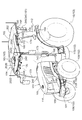
前記電子制御システムは、衛星航法用のアンテナユニットを備え、前記アンテナユニットは、前記キャビンのルーフにおける左右中央箇所に取り付けられ、
前記ルーフは、前記アンテナユニット周辺の上面が前後方向に傾斜する傾斜面に形成され、
前記ルーフの左右両端箇所に、前記ルーフの前後両端にわたる前後長さを有し、前記左右両端箇所から上方に膨出する左右の膨出縁部と、ルーフ上の水を、前記アンテナユニットを迂回するように左右の前記膨出縁部に向けて案内する水切り溝と、が備えられている作業車。 [1] In view of [Problem 1], the following work vehicles are proposed.
An electronic control system for automatic driving that automatically drives the vehicle body,
A cabin that forms a boarding space,
The electronic control system includes an antenna unit for satellite navigation, and the antenna unit is attached to a left and right center portion of the roof of the cabin,
The roof is formed on an inclined surface in which an upper surface around the antenna unit is inclined in the front-rear direction,
Left and right end portions of the roof have front and rear lengths extending from the front and rear ends of the roof, and left and right bulging edges that bulge upward from the left and right end portions, and water on the roof bypass the antenna unit. And a draining groove for guiding the left and right bulging edges toward the left and right bulging edges.
車体を自動で運転する自動運転用の電子制御システムと、
搭乗空間を形成するキャビンと、を備え、
前記電子制御システムは、衛星航法用のアンテナユニットを備え、前記アンテナユニットは、前記キャビンのルーフにおける左右中央箇所に取り付けられ、
前記ルーフは、前記アンテナユニット周辺の上面が前後方向に傾斜する傾斜面に形成され、
前記ルーフの左右両端箇所に、前記ルーフの前後両端にわたる前後長さを有し、前記左右両端箇所から上方に膨出する左右の膨出縁部と、ルーフ上の水を、前記アンテナユニットを迂回するように左右の前記膨出縁部に向けて案内する水切り溝と、が備えられている作業車。 [1] In view of [Problem 1], the following work vehicles are proposed.
An electronic control system for automatic driving that automatically drives the vehicle body,
A cabin that forms a boarding space,
The electronic control system includes an antenna unit for satellite navigation, and the antenna unit is attached to a left and right center portion of the roof of the cabin,
The roof is formed on an inclined surface in which an upper surface around the antenna unit is inclined in the front-rear direction,
Left and right end portions of the roof have front and rear lengths extending from the front and rear ends of the roof, and left and right bulging edges that bulge upward from the left and right end portions, and water on the roof bypass the antenna unit. And a draining groove for guiding the left and right bulging edges toward the left and right bulging edges.
これによれば、ルーフの上面に降りかかった雨水や洗浄水などは、水切り溝の案内作用により、アンテナユニットを迂回しながら左右の膨出縁部に向けて流れ易くなる。そして、左右の膨出縁部に向けて流れた雨水や洗浄水などは、傾斜面の案内作用により、左右中央のアンテナユニットから離れた左右両端の膨出縁部に沿って傾斜面の下方に向けて流れ易くなり、この流れによって、傾斜面の下方側に位置するルーフの前後一端縁からルーフの下方に流れ落ちる。
According to this, rainwater or washing water that has fallen on the top surface of the roof is likely to flow toward the left and right bulging edges while bypassing the antenna unit by the guide action of the draining groove. And rainwater and washing water that flowed toward the left and right bulging edges are below the inclined surface along the left and right bulging edge portions away from the left and right center antenna units by the guiding action of the inclined surface. The flow tends to flow toward the lower side of the roof from the front and rear edges of the roof located on the lower side of the inclined surface.
これにより、アンテナユニット取り付け用の台座をルーフの上面に膨出形成しなくても、ルーフの上面に降りかかった雨水や洗浄水などを、ルーフの左右中央に位置するアンテナユニットに向けて流れ難くすることができる。
This makes it difficult for rainwater and washing water that has fallen on the top surface of the roof to flow toward the antenna unit located at the left and right center of the roof, without the base for mounting the antenna unit being bulged on the top surface of the roof. can do.
その結果、アンテナユニットを含む車体の全高が高くなることを抑制しながら、雨水や洗浄水などがアンテナユニットに悪影響を及ぼす虞、及び、アンテナユニットの取り付け箇所からルーフ内に浸入する虞を回避することができる。
As a result, while preventing the overall height of the vehicle body including the antenna unit from being increased, it is possible to avoid the possibility that rainwater, washing water, etc. may adversely affect the antenna unit, and that the antenna unit may enter the roof from the location where the antenna unit is attached. be able to.
又、雨天での作業走行中においては、ルーフの上面に降りかかった雨水の多くが、ルーフの左右両端箇所に形成された左右の膨出部に沿って傾斜面の下方に向けて流れた後、ルーフにおける前後一端縁の左右両端側からルーフの下方に流れ落ちることから、ルーフから流れ落ちる雨水に起因した前方視認性の低下を抑制することができる。
Also, during work in rainy weather, most of the rainwater that has fallen on the top surface of the roof flows down the inclined surface along the left and right bulges formed at the left and right ends of the roof. In addition, since it flows down from the left and right ends of the front and rear end edges of the roof to the lower side of the roof, it is possible to suppress a decrease in forward visibility due to rainwater flowing down from the roof.
一好適実施形態では、前記水切り溝は、前記傾斜面における前記アンテナユニットよりも高位側の位置にて前記左右の膨出縁部にわたる左右向きの第1溝部と、前記第1溝部の左右の端部から前記ルーフにおける前後一端縁の左右両端部に向けて左右の前記膨出縁部を横切る左右の第2溝部と、を有する。
In one preferred embodiment, the draining groove includes a first groove part extending in the left-right direction across the left and right bulging edges at a position higher than the antenna unit on the inclined surface, and left and right ends of the first groove part. Left and right second groove portions that cross the left and right bulging edge portions from the portion toward the left and right end portions of the front and rear end edges of the roof.
これによれば、ルーフの上面に降りかかった雨水や洗浄水などは、傾斜面の案内作用によってアンテナユニット側に向けて流れる途中において、第1溝部に流れ込んで第1溝部の案内作用を受けるようになり、この案内作用によって左右の膨出縁部に向けて流れ易くなる。そして、左右の膨出縁部に向けて流れた雨水や洗浄水などは、その多くが、左右の第2溝部の案内作用を受けて、左右の膨出縁部を横切りながらルーフにおける前後一端縁の左右両端部に向けて流れた後、左右の膨出縁部の車体横外側に位置する前後一端縁の左右両端部からルーフの下方に流れ落ちる。
According to this, rain water, washing water, or the like that has fallen on the upper surface of the roof flows into the first groove portion and is guided by the first groove portion while flowing toward the antenna unit side by the guide operation of the inclined surface. This guide action facilitates the flow toward the left and right bulging edges. And most of the rain water and washing water that flow toward the left and right bulging edges receive the guiding action of the left and right second groove portions, and cross the left and right bulging edges, and the front and rear end edges of the roof After flowing toward both left and right end portions of the left and right, it flows down from the left and right end portions of the front and rear end edges located on the laterally outer sides of the left and right bulging edges to the lower side of the roof.
これにより、ルーフの上面に降りかかった雨水や洗浄水などを、より確実にルーフの左右中央に位置するアンテナユニットに向けて流れ難くすることができる。その結果、雨水や洗浄水などがアンテナユニットに悪影響を及ぼす虞、及び、アンテナユニットの取り付け箇所からルーフ内に浸入する虞をより確実に回避することができる。
This makes it possible to more reliably prevent rainwater and washing water that has fallen on the top surface of the roof from flowing toward the antenna unit located at the center of the left and right sides of the roof. As a result, it is possible to more reliably avoid the possibility that rainwater, washing water, etc. will adversely affect the antenna unit and that it may enter the roof from the location where the antenna unit is attached.
又、雨天での作業走行中においては、ルーフの上面に降りかかった雨水の多くが、左右の膨出縁部の車体横外側に位置するルーフにおける前後一端縁の左右両端部からルーフの下方に流れ落ちることから、ルーフから流れ落ちる雨水に起因した前方視認性の低下をより効果的に抑制することができる。
Also, during work in rainy weather, most of the rainwater that has fallen on the upper surface of the roof is below the roof from the left and right ends of the front and rear end edges of the roof located on the laterally outer sides of the left and right bulging edges. Since it flows down, the fall of forward visibility resulting from the rain water flowing down from a roof can be suppressed more effectively.
一好適実施形態では、前記ルーフにおける前記アンテナユニットに隣接する前記傾斜面の高位側箇所に、前記アンテナユニットに対するコネクタ接続用の凹部が形成されている。
In a preferred embodiment, a concave portion for connecting a connector to the antenna unit is formed at a higher position of the inclined surface adjacent to the antenna unit in the roof.
これによれば、ルーフにおけるアンテナユニットの周辺に傾斜面を形成して、アンテナユニットの周辺での水捌けを良好にしながらも、ルーフの上面にアンテナユニット取り付け用の台座を膨出形成することなく、アンテナユニットに対するコネクタの接続を行い易くすることができる。
According to this, an inclined surface is formed around the antenna unit in the roof, and water drainage around the antenna unit is good, but without forming a base for mounting the antenna unit on the upper surface of the roof, The connector can be easily connected to the antenna unit.
一好適実施形態では、前記ルーフにおける前記アンテナユニットとの隣接箇所に通信アンテナが取り付けられ、
前記ルーフには、前記アンテナユニットに接続されたケーブルと前記通信アンテナに接続されたケーブルとを前記ルーフの下方に位置決め案内する左右の案内溝を備え、
左右の前記案内溝は、前記傾斜面に形成された第1案内部と、左右の前記膨出縁部に形成された第2案内部とを有する。 In one preferred embodiment, a communication antenna is attached to a portion of the roof adjacent to the antenna unit,
The roof includes left and right guide grooves for positioning and guiding a cable connected to the antenna unit and a cable connected to the communication antenna below the roof,
The left and right guide grooves include a first guide portion formed on the inclined surface and a second guide portion formed on the left and right bulging edges.
これによれば、アンテナユニット用のケーブルと通信アンテナ用のケーブルとを、ルーフの上面から上方にはみ出させることなく、左右の案内溝に沿ってルーフの上面側からルーフの下方に向けて配索することができる。これにより、アンテナユニット用のケーブル及び通信アンテナ用のケーブルが、ルーフの上面から浮きがって他物に引っ掛かる虞を回避することができる。
又、ルーフの上面にケーブル挿通用の貫通孔を形成する必要がないことから、ケーブル挿通用の貫通孔からの浸水を防止する防水部材が不要になる。その結果、部品点数の削減による構成の簡素化などを図ることができる。 According to this, the cable for the antenna unit and the cable for the communication antenna are routed from the upper surface side of the roof toward the lower side of the roof along the left and right guide grooves without protruding upward from the upper surface of the roof. can do. As a result, it is possible to avoid the possibility that the antenna unit cable and the communication antenna cable may be lifted from the top surface of the roof and caught on other objects.
Further, since it is not necessary to form a through hole for inserting a cable on the upper surface of the roof, a waterproof member for preventing water from entering through the through hole for inserting a cable becomes unnecessary. As a result, it is possible to simplify the configuration by reducing the number of parts.
[2][課題2]に鑑み、以下の作業車が提案される。
車体を自動で運転する自動運転用の電子制御システムと、
搭乗空間を形成するキャビンと、を備え、
前記電子制御システムは、遠隔操作具との間で無線通信する通信モジュールを備え、
前記通信モジュールは、前記キャビンのルーフに取り付けられる通信アンテナと、前記通信アンテナの通信感度を高めるエレメントとを備え、
前記エレメントは、前記ルーフの内部空間に収納されている作業車。 [2] In view of [Problem 2], the following work vehicles are proposed.
An electronic control system for automatic driving that automatically drives the vehicle body,
A cabin that forms a boarding space,
The electronic control system includes a communication module that wirelessly communicates with a remote control tool,
The communication module includes a communication antenna attached to a roof of the cabin, and an element for increasing communication sensitivity of the communication antenna,
The working element is housed in an inner space of the roof.
これによれば、エレメントによって通信アンテナの電波利得を高めることができることにより、通信アンテナの小型化を図ることができる。そして、この小型化により、通信アンテナの通信感度を高めるために、通信アンテナをキャビンのルーフに取り付けても、通信アンテナを含めた車体の全高を低く抑えることができる。又、エレメントがルーフの内部空間に収納されることにより、エレメントをルーフの外部に備える場合に比較して、通信アンテナとエレメントとをキャビンのルーフにコンパクトに備えることができる。
その結果、通信アンテナを含む車体の全高が高くなることを抑制しながら、通信アンテ
ナの通信性能を高めることができる。 According to this, since the radio wave gain of the communication antenna can be increased by the element, the size of the communication antenna can be reduced. With this downsizing, the overall height of the vehicle body including the communication antenna can be kept low even if the communication antenna is attached to the cabin roof in order to increase the communication sensitivity of the communication antenna. Further, by accommodating the element in the interior space of the roof, the communication antenna and the element can be provided more compactly on the roof of the cabin than when the element is provided outside the roof.
As a result, it is possible to improve the communication performance of the communication antenna while suppressing an increase in the overall height of the vehicle body including the communication antenna.
一好適実施形態では、前記エレメントは、前記ルーフのルーフフレームに連結されるとともに、前記ルーフのアウタルーフを介して前記通信アンテナを支持している。
In one preferred embodiment, the element is connected to the roof frame of the roof and supports the communication antenna via the outer roof of the roof.
これによれば、エレメントを、ルーフのアウタルーフ及び通信アンテナを支持する支持部材に兼用することができる。
According to this, the element can be used also as a support member for supporting the outer roof of the roof and the communication antenna.
その結果、部品点数の削減による構成の簡素化などを図ることができる。
As a result, it is possible to simplify the configuration by reducing the number of parts.
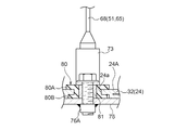
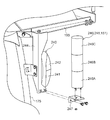
一好適実施形態では、前記ルーフは、前記通信アンテナを支持する支持具と前記エレメントとがボルト連結される連結部を備え、
前記連結部は、ボルト連結用の複数の貫通孔と、前記貫通孔に嵌め込まれた複数のゴムスリーブとを備え、
前記ゴムスリーブは、上側フランジ部と下側フランジ部とを有し、
前記連結部において前記支持具と前記エレメントとがボルト連結されると、前記上側フランジ部は前記ルーフの上面と前記支持具の底面とに密接し、前記下側フランジ部は前記ルーフの内面と前記エレメントの上面とに密接する。 In one preferred embodiment, the roof includes a connection part to which the support member supporting the communication antenna and the element are bolted,
The connecting portion includes a plurality of through holes for bolt connection and a plurality of rubber sleeves fitted into the through holes,
The rubber sleeve has an upper flange portion and a lower flange portion,
When the support and the element are bolted in the connecting portion, the upper flange portion is in close contact with the upper surface of the roof and the bottom surface of the support, and the lower flange portion is connected to the inner surface of the roof and the roof. Close to the top surface of the element.
これによれば、支持具とエレメントとがルーフの連結部にボルト連結された状態では、ゴムスリーブの上側フランジ部がルーフの上面と支持具の底面とに密接し、又、ゴムスリーブの下側フランジ部がルーフの内面とエレメントの上面とに密接することにより、雨水や洗浄水などが、連結部の各貫通孔からキャビンの内部に浸入することが防止される。
According to this, in a state where the support and the element are bolted to the connecting portion of the roof, the upper flange portion of the rubber sleeve is in close contact with the upper surface of the roof and the bottom surface of the support, and the lower side of the rubber sleeve When the flange portion is in close contact with the inner surface of the roof and the upper surface of the element, rain water, washing water, and the like are prevented from entering the interior of the cabin from each through hole of the connecting portion.
つまり、上下のフランジ部を有する複数のゴムスリーブが防水部材を兼ねることから、部品点数の削減による構成の簡素化を図りながらキャビンの内部への浸水を防止すること
ができる。 That is, since the plurality of rubber sleeves having the upper and lower flange portions also serve as a waterproof member, it is possible to prevent water from entering the cabin while simplifying the configuration by reducing the number of parts.
ができる。 That is, since the plurality of rubber sleeves having the upper and lower flange portions also serve as a waterproof member, it is possible to prevent water from entering the cabin while simplifying the configuration by reducing the number of parts.
[3][課題3]に鑑み、以下の作業車が提案される。
車体の後部側に配置されたキャビンと、
車体を自動で運転する自動運転用の電子制御システムとを備え、
前記電子制御システムは、慣性計測装置を内部に有する衛星航法用のアンテナユニットを備え、
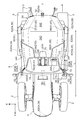
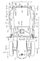
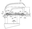
前記アンテナユニットは、車体におけるトレッドの中央部でホイールベースの中央部に位置するように、前記キャビンのルーフにおける前部上面の左右中央箇所に取り付けられている作業車。 [3] In view of [Problem 3], the following work vehicles are proposed.
A cabin located on the rear side of the car body,
And an electronic control system for automatic driving that automatically drives the vehicle body,
The electronic control system includes an antenna unit for satellite navigation having an inertial measurement device therein,
The work vehicle is attached to the left and right central portions of the upper surface of the front portion of the cabin roof so that the antenna unit is positioned at the center of the wheel base at the center of the tread in the vehicle body.
車体の後部側に配置されたキャビンと、
車体を自動で運転する自動運転用の電子制御システムとを備え、
前記電子制御システムは、慣性計測装置を内部に有する衛星航法用のアンテナユニットを備え、
前記アンテナユニットは、車体におけるトレッドの中央部でホイールベースの中央部に位置するように、前記キャビンのルーフにおける前部上面の左右中央箇所に取り付けられている作業車。 [3] In view of [Problem 3], the following work vehicles are proposed.
A cabin located on the rear side of the car body,
And an electronic control system for automatic driving that automatically drives the vehicle body,
The electronic control system includes an antenna unit for satellite navigation having an inertial measurement device therein,
The work vehicle is attached to the left and right central portions of the upper surface of the front portion of the cabin roof so that the antenna unit is positioned at the center of the wheel base at the center of the tread in the vehicle body.
これによれば、アンテナユニットがキャビンのルーフ上面に取り付けられていることから、アンテナユニットによる衛星からの電波の受信感度が高くなる。又、慣性計測装置の取り付け位置が、前述した通りアンテナユニットの取り付け位置によって決まることから、慣性計測装置の位置調整に応じて車体の重心位置からの慣性計測装置の位置ズレ量を求める必要がなくなる。しかも、慣性計測装置の取り付け位置がユーザーなどによって安易に変更される虞もない。
According to this, since the antenna unit is attached to the upper surface of the roof of the cabin, the reception sensitivity of the radio wave from the satellite by the antenna unit is increased. Further, since the mounting position of the inertial measurement device is determined by the mounting position of the antenna unit as described above, it is not necessary to obtain the displacement amount of the inertial measurement device from the center of gravity position of the vehicle body in accordance with the position adjustment of the inertial measurement device. . Moreover, there is no possibility that the attachment position of the inertial measurement device is easily changed by a user or the like.
そして、慣性計測装置が、車体におけるトレッドの中央部でホイールベースの中央部に配置されることにより、少なくとも、平面視においては慣性計測装置の取り付け位置が車体の重心位置に近くなる。これにより、慣性計測装置が計測したヨー角などを、慣性計測装置の位置ズレ量に基づいて補正するための演算が簡単になり、よって、慣性計測装置の計測結果を迅速に正しく補正することができる。つまり、慣性計測装置による車体のヨー角などの計測を迅速に精度良く行うことができる。
The inertial measurement device is arranged at the center of the wheel base at the center of the tread in the vehicle body, so that the attachment position of the inertial measurement device is close to the center of gravity of the vehicle body at least in plan view. As a result, the calculation for correcting the yaw angle measured by the inertial measurement device based on the positional deviation amount of the inertial measurement device is simplified, so that the measurement result of the inertial measurement device can be corrected quickly and correctly. it can. That is, it is possible to quickly and accurately measure the yaw angle of the vehicle body by the inertial measurement device.
これにより、全地球航法衛星システムを利用して車体の位置及び方位を測定する場合において、車体のヨーイング、ピッチング、又は、ローリングに起因して、アンテナユニットに位置ズレが生じたときは、このときのアンテナユニットの位置ズレ量を、慣性計測装置が計測する車体のヨー角、ピッチ角、ロール角、などから迅速に精度良く求めることができる。そして、全地球航法衛星システムを利用して計測した車体の位置及び方位に含まれるアンテナユニットの位置ズレに起因した測位誤差を、慣性計測装置の計測結果から求められるアンテナユニットの位置ズレ量に基づいて迅速に精度良く求めることができ、この測位誤差を測定結果から取り除く補正を迅速かつ適正に行える。
As a result, when the position and orientation of the vehicle body is measured using the global navigation satellite system, if the antenna unit is misaligned due to the yawing, pitching, or rolling of the vehicle body, The position deviation amount of the antenna unit can be quickly and accurately obtained from the yaw angle, pitch angle, roll angle, etc. of the vehicle body measured by the inertial measurement device. The positioning error caused by the positional deviation of the antenna unit included in the position and orientation of the vehicle body measured using the global navigation satellite system is based on the positional deviation amount of the antenna unit obtained from the measurement result of the inertial measurement device. Therefore, the correction for removing this positioning error from the measurement result can be performed quickly and appropriately.
その結果、全地球航法衛星システムを利用した車体の位置及び方位の測定を、より簡単かつ迅速に精度良く行うことができる。
As a result, measurement of the position and orientation of the vehicle body using the global navigation satellite system can be performed more easily, quickly and accurately.
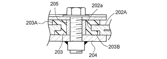
一好適実施形態では、前記ルーフは、前記アンテナユニットがボルト連結される連結部を備え、
前記連結部は、ボルト連結用の複数の貫通孔と、前記貫通孔に嵌め込まれた複数のゴムスリーブとを備え、
前記ゴムスリーブはフランジ部を備え、
前記アンテナユニットが前記ルーフの前記連結部にボルト連結されると、前記フラン時部が前記ルーフの上面と前記アンテナユニットの底面とに密接する。 In one preferred embodiment, the roof includes a connecting portion to which the antenna unit is bolted,
The connecting portion includes a plurality of through holes for bolt connection and a plurality of rubber sleeves fitted into the through holes,
The rubber sleeve includes a flange portion,
When the antenna unit is bolted to the connecting portion of the roof, the furan hour portion is in close contact with the top surface of the roof and the bottom surface of the antenna unit.
これによれば、アンテナユニットがルーフの連結部にボルト連結された状態では、ゴムスリーブのフランジ部が、ルーフの上面とアンテナユニットの底面との間に位置することにより、車体側の振動がアンテナユニットに伝わり難くなる。そして、ゴムスリーブのフランジ部が、ルーフの上面とアンテナユニットの底面とに密接することにより、雨水や洗浄水などが、連結部の各貫通孔からキャビンの内部に浸入することが防止される。
According to this, in a state where the antenna unit is bolted to the connecting portion of the roof, the flange portion of the rubber sleeve is located between the top surface of the roof and the bottom surface of the antenna unit, so that vibration on the vehicle body side is not caused by the antenna. Difficult to get to the unit The flange portion of the rubber sleeve is in close contact with the top surface of the roof and the bottom surface of the antenna unit, so that rain water, washing water, and the like are prevented from entering the cabin through the through holes of the connecting portion.
つまり、フランジ部を有する複数のゴムスリーブが、防振部材と防水部材とを兼ねることから、構成の簡素化を図りながら、アンテナユニットを防振支持することができるとともに、キャビンの内部への浸水を防止することができる。
In other words, since the plurality of rubber sleeves having the flange portion serve as both a vibration isolating member and a waterproof member, the antenna unit can be supported in an anti-vibration manner while simplifying the configuration, and water can enter the cabin. Can be prevented.
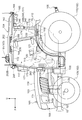
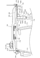
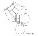
一好適実施形態では、前記ルーフにおける前部の上面が前下がりに形成され、
前記ルーフにおける前記前部の左右中央箇所に、アンテナユニット取り付け用の台座が上向きに膨出形成されている。 In one preferred embodiment, the upper surface of the front portion of the roof is formed to be front-lowering,
A pedestal for attaching the antenna unit is formed to bulge upward at the left and right central portions of the front portion of the roof.
これによれば、ルーフの上面に降りかかった雨水や洗浄水などは、アンテナユニットの周辺に滞留することなく、速やかにルーフの前側に流れてルーフの前端から下方に流れ落ちる。そして、このように、アンテナユニットの周辺での水はけを良好にしながらも、アンテナユニットが取り付けられる台座の座面を、ルーフの前部上面とは異なるアンテナユニットの取り付けに適した水平面などに形成することができる。
According to this, rain water, washing water or the like that has fallen on the top surface of the roof flows quickly to the front side of the roof and falls downward from the front end of the roof without staying around the antenna unit. In this way, the seat surface of the pedestal to which the antenna unit is attached is formed on a horizontal surface suitable for mounting the antenna unit different from the front upper surface of the roof while the drainage around the antenna unit is improved. be able to.
その結果、雨水や洗浄水などがアンテナユニットの周辺に滞留してアンテナユニットなどに悪影響を及ぼすことを防止しながら、アンテナユニットの取り付け姿勢を適正にすることができる。
As a result, the installation posture of the antenna unit can be made appropriate while preventing rainwater, washing water, etc. from staying around the antenna unit and adversely affecting the antenna unit.
又、アンテナユニットが取り付けられるルーフの前部上面は、前下がりに形成されることにより、ルーフの後部上面よりも低くなることから、アンテナユニットがルーフの後部上面に取り付けられる場合に比べて、アンテナユニットを含む車高が低くなる。これにより、作業車が格納される納屋などに対する出入口からの作業車の出し入れが行い易くなる。
In addition, since the front upper surface of the roof to which the antenna unit is attached is formed so as to be lowered downward, it is lower than the rear upper surface of the roof, so that the antenna unit is more than the case where the antenna unit is attached to the rear upper surface of the roof. The vehicle height including the unit is lowered. Thereby, it becomes easy to take in and out the work vehicle from the entrance to the barn or the like in which the work vehicle is stored.
一好適実施形態では、前記ルーフの上面に、前記アンテナユニットの取り付け箇所からルーフ前縁の左右両端部にわたって水切り溝が形成されている。
In a preferred embodiment, drainage grooves are formed on the upper surface of the roof from the mounting position of the antenna unit to the left and right ends of the front edge of the roof.
これによれば、アンテナユニットの周辺に降りかかった雨水や洗浄水などは、水切り溝に沿って、アンテナユニットの周辺からルーフ前縁の左右両端部に向けて流れ易くなる。そして、ルーフ前縁の左右両端部に達した雨水や洗浄水などは、ルーフ前縁の左右両端部から下方に流れ落ちる。
According to this, rain water, washing water, etc. that has fallen around the antenna unit can easily flow from the periphery of the antenna unit toward the left and right ends of the roof front edge along the draining groove. And rain water, washing water, etc. which reached the left and right ends of the roof front edge flow downward from the left and right ends of the roof front edge.
その結果、雨水や洗浄水などがアンテナユニットの周辺に滞留してアンテナユニットなどに悪影響を及ぼすことを防止することができる。又、雨天での作業走行中においては、ルーフの上面に降りかかった雨水の多くが、ルーフ前縁の左右両端部から下方に流れ落ちることから、ルーフから流れ落ちる雨水に起因した前方視認性の低下を抑制することができる。
As a result, it is possible to prevent rainwater or washing water from staying around the antenna unit and adversely affecting the antenna unit. In addition, during work in rainy weather, most of the rainwater that has fallen on the top surface of the roof flows down from the left and right ends of the front edge of the roof. Can be suppressed.
[4][課題4]に鑑み、以下の作業車が提案される。
車体を自動で運転する自動運転用の電子制御システムを備え、
前記電子制御システムは、自動運転中の車体の運転状況を外部から視認可能に表示する外部表示ユニットを備え、
前記外部表示ユニットは、車体の左右両側部に配置された左右の表示灯と、自動運転中の車体の運転状況に応じて前記表示灯の作動を制御するように構成された外部表示制御部とを備える作業車。 [4] In view of [Problem 4], the following work vehicles are proposed.
Equipped with an electronic control system for automatic driving that automatically drives the car body,
The electronic control system includes an external display unit that displays the driving status of the vehicle body during automatic driving so that the driving status can be viewed from the outside.
The external display unit includes left and right indicator lamps arranged on both left and right sides of the vehicle body, and an external display control unit configured to control the operation of the indicator light according to the driving state of the vehicle body during automatic operation. Work vehicle equipped with.
これによれば、左右の表示灯が車体の左右両側部に配置されることにより、車高が高くなるのを防止するために、各表示灯の全体が車体の上端から上方に突出しないように配置されていても、自動運転中の作業車の外部に居る管理者は、左右いずれか一方の表示灯の作動状態を容易に視認することができる。そして、この視認により、管理者は、自動運転中の作業車における車体の運転状況を容易に把握することができる。
According to this, in order to prevent the vehicle height from being increased by arranging the left and right indicator lamps on the left and right sides of the vehicle body, the whole of the indicator lights should not protrude upward from the upper end of the vehicle body. Even if it is arranged, the manager who is outside the work vehicle during automatic driving can easily visually recognize the operating state of either the left or right indicator lamp. And by this visual recognition, the administrator can easily grasp the driving situation of the vehicle body in the work vehicle during automatic driving.
その結果、納屋などに対する作業車の出し入れを行い難くすることなく、自動運転中の作業車における車体の運転状況を、左右の表示灯の作動によって車外の管理者に容易に把握させることができる。
As a result, without making it difficult to put the work vehicle in and out of the barn etc., it is possible for the manager outside the vehicle to easily grasp the driving situation of the vehicle body in the work vehicle during automatic driving by operating the left and right indicator lights.
一好適実施形態では、前記表示灯は、表示色が異なる複数の表示部が積層された積層表示灯を備え、
前記積層表示灯は、前記複数の表示部が上下方向に並ぶ縦長姿勢で、車体の左右両側部に配置されている。 In one preferred embodiment, the indicator lamp includes a laminated display lamp in which a plurality of display units having different display colors are laminated,
The stacked indicator lamp is disposed on both left and right sides of the vehicle body in a vertically long posture in which the plurality of display portions are arranged in the vertical direction.
これによれば、自動運転中の車体の運転状況に応じて、表示灯の作動状態を変更するだけでなく、作動する表示部を変更することができる。これにより、自動運転中の作業車におけるより多くの車体の運転状況を、車外の管理者に容易に把握させることができる。
According to this, not only the operating state of the indicator lamp can be changed but also the operating indicator can be changed according to the driving state of the vehicle body during automatic driving. This makes it possible for the manager outside the vehicle to easily grasp the driving situation of more vehicle bodies in the work vehicle being automatically driven.
そして、複数の表示部が左右方向に並ぶ横長姿勢で車体の左右両側部に配置される構成に比べて、左右の積層表示灯を、各積層表示灯の車体からの張り出し量を少なくしながら、各表示部の作動状態を作業車の外部から視認し易い状態で車体に備えることができる。
And, compared to the configuration in which the plurality of display units are arranged on the left and right sides of the vehicle body in a horizontally long posture in which the display units are arranged in the left and right direction, while reducing the amount of overhang from the vehicle body of each stacked display lamp, The operation state of each display unit can be provided in the vehicle body in a state where it can be easily seen from the outside of the work vehicle.
その結果、車体の大型化を抑制しながら、自動運転中の作業車におけるより多くの車体の運転状況を、左右の表示灯の作動によって車外の管理者に容易に把握させることができる。
As a result, while suppressing the increase in size of the vehicle body, it is possible for the manager outside the vehicle to easily grasp the driving state of more vehicle bodies in the work vehicle during automatic driving by operating the left and right indicator lights.
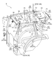
一好適実施形態では、前記車体に、搭乗空間を形成するキャビンが搭載され、
前記積層表示灯は、前記キャビンにおける左右のリアピラーの横外側に配置されている。 In one preferred embodiment, a cabin that forms a boarding space is mounted on the vehicle body,
The laminated indicator lamp is disposed on the lateral outer sides of the left and right rear pillars in the cabin.
前記積層表示灯は、前記キャビンにおける左右のリアピラーの横外側に配置されている。 In one preferred embodiment, a cabin that forms a boarding space is mounted on the vehicle body,
The laminated indicator lamp is disposed on the lateral outer sides of the left and right rear pillars in the cabin.
これによれば、作業車にキャビンが備えられていても、車外の管理者は、左右いずれか一方の積層表示灯の作動状態を、キャビンによって阻害されることなく視認することができる。つまり、キャビンを備えながら、自動運転中の作業車における車体の運転状況を、左右の積層表示灯の作動によって車外の管理者に容易に把握させることができる。
According to this, even if the work vehicle is equipped with a cabin, an administrator outside the vehicle can visually recognize the operating state of either the left or right stacked indicator lamp without being obstructed by the cabin. That is, it is possible to make it possible for the manager outside the vehicle to easily grasp the driving state of the vehicle body in the work vehicle that is being automatically driven by operating the left and right stacked indicator lamps while having the cabin.
一好適実施形態では、前記積層表示灯は、左右の走行装置の横外端よりも車体内側で、前記キャビンのルーフよりも車体下側の位置に配置されている。
In one preferred embodiment, the laminated indicator lamp is disposed at a position inside the vehicle body from the lateral outer ends of the left and right traveling apparatuses and at a position below the vehicle body from the roof of the cabin.
これによれば、左右の積層表示灯は、キャビンのルーフよりも車体下側における車体の前後長さ内で車体の左右幅内の位置に配置されることになる。これにより、左右の積層表示灯を、車外の管理者から視認し易い左右のリアピラーの横外側に配置しながらも、作業車を納屋などの出入口から出し入れするときに、左右の積層表示灯が納屋などに接触する虞を回避することができる。
According to this, the left and right stacked indicator lamps are arranged at positions within the lateral width of the vehicle body within the longitudinal length of the vehicle body below the cabin roof. As a result, the left and right stacked indicator lamps are placed on the laterally outer sides of the left and right rear pillars that are easily visible to the manager outside the vehicle, but the left and right stacked indicator lamps are It is possible to avoid the possibility of contact with the like.
一好適実施形態では、前記キャビンは、ブレーキランプとウインカーランプとを有するコンビネーションランプを支持する支持部材を備え、
前記積層表示灯は、前記コンビネーションランプの横外側に位置するように前記支持部材に支持されている。 In one preferred embodiment, the cabin includes a support member that supports a combination lamp having a brake lamp and a blinker lamp,
The laminated indicator lamp is supported by the support member so as to be positioned laterally outside the combination lamp.
これによれば、支持部材を積層表示灯の支持に利用しながら、車体前方又は車体後方からのコンビネーションランプの視認を阻害しない状態で、積層表示灯を左右のリアピラーの横外側に配置することができる。これにより、部品の兼用化による構成の簡素化を図りながら、左右の積層表示灯を、車外の管理者から視認し易い左右のリアピラーの横外側に好適に配置することができる。
According to this, it is possible to arrange the stacked indicator lamps on the lateral outer sides of the left and right rear pillars in a state in which the visibility of the combination lamp from the front of the vehicle body or the rear of the vehicle body is not obstructed while using the support member for supporting the stacked indicator lamps. it can. Accordingly, the left and right stacked indicator lamps can be suitably disposed on the lateral outer sides of the left and right rear pillars that are easily visible to the manager outside the vehicle, while simplifying the configuration by sharing the parts.
一好適実施形態では、前記表示灯は、ウインカーランプを備え、
前記外部表示制御部は、自動運転中の車体の運転状況に応じて前記ウインカーランプの作動を制御するように構成されている。 In one preferred embodiment, the indicator lamp comprises a blinker lamp,
The external display control unit is configured to control the operation of the winker lamp according to the driving state of the vehicle body during automatic driving.
これによれば、圃場内での走行においては特に作動させる必要のない左右のウインカーランプを、自動運転中の車体の運転状況を車外の管理者などに把握させる表示灯に有効利用することができる。そして、左右のウインカーランプは、本来より、車外の人が視認し易い位置に配置されていることから、ウインカーランプの作動状態を車外の管理者などに容易に認識させることができる。つまり、部品の兼用化による構成の簡素化を図りながら、自動運転中の作業車における車体の運転状況を車外の管理者などに把握させることができる。
According to this, it is possible to effectively use the left and right turn signal lamps that do not need to be operated particularly during traveling in the field as an indicator light that allows a manager or the like outside the vehicle to grasp the driving state of the vehicle body during automatic driving. . Since the left and right turn signal lamps are originally arranged at positions that are easily visible to people outside the vehicle, the operating state of the turn signal lamps can be easily recognized by an administrator outside the vehicle. In other words, it is possible to allow an administrator outside the vehicle to grasp the driving state of the vehicle body in the work vehicle during automatic driving while simplifying the configuration by sharing the parts.
又、ウインカーランプを表示灯に有効利用しながら別の表示灯を備えるようにすれば、コストの上昇を抑制しながら、自動運転中の作業車におけるより多くの車体の運転状況を、車外の管理者などに容易に把握させることができる。
In addition, if another indicator light is provided while effectively using the blinker lamp as an indicator light, it is possible to control the operation status of more vehicle bodies in a work vehicle during automatic operation while controlling the increase in cost. Can be easily grasped by a person.
[5]その他の特徴構成、及び、これから奏する有利な効果については、以下の説明を読めば明らかになるだろう。
[5] Other characteristic configurations and advantageous effects to be achieved will be apparent from the following description.
以下の説明では、図1に記載された符号Fの矢印が指し示す方向がトラクタの前側であり、符号Uの矢印が指し示す方向がトラクタの上側である。
又、図2に記載された符号Fの矢印が指し示す方向がトラクタの前側であり、符号Rの矢印が指し示す方向がトラクタの右側である。 In the following description, the direction indicated by the arrow F shown in FIG. 1 is the front side of the tractor, and the direction indicated by the arrow U is the upper side of the tractor.
2 is the front side of the tractor, and the direction indicated by the arrow R is the right side of the tractor.
[第1実施形態]
図1~3に示すように、本実施形態に例示されたトラクタ(作業車の一例)は、車体の前後両端にわたる車体フレーム1、駆動可能な操舵輪として機能する左右の前輪2、駆動輪として機能する左右の後輪3、車体フレーム1の前部側に配置された原動部4、車体フレーム1の後部側に搭乗空間と運転部5とを形成するキャビン6、及び、車体フレーム1の後端部に昇降揺動可能に取り付けられた作業装置連結用の3点リンク機構7、などを備えている。 [First Embodiment]
As shown in FIGS. 1 to 3, a tractor (an example of a work vehicle) exemplified in the present embodiment includes a body frame 1 that extends over both front and rear ends of a vehicle body, left and rightfront wheels 2 that function as drivable steering wheels, and drive wheels. Left and right rear wheels 3 that function, a driving unit 4 disposed on the front side of the body frame 1, a cabin 6 that forms a riding space and a driving unit 5 on the rear side of the body frame 1, and the rear of the body frame 1 A three-point link mechanism 7 for connecting the work device, which is attached to the end portion so as to be movable up and down, is provided.
図1~3に示すように、本実施形態に例示されたトラクタ(作業車の一例)は、車体の前後両端にわたる車体フレーム1、駆動可能な操舵輪として機能する左右の前輪2、駆動輪として機能する左右の後輪3、車体フレーム1の前部側に配置された原動部4、車体フレーム1の後部側に搭乗空間と運転部5とを形成するキャビン6、及び、車体フレーム1の後端部に昇降揺動可能に取り付けられた作業装置連結用の3点リンク機構7、などを備えている。 [First Embodiment]
As shown in FIGS. 1 to 3, a tractor (an example of a work vehicle) exemplified in the present embodiment includes a body frame 1 that extends over both front and rear ends of a vehicle body, left and right
図1に示すように、トラクタは、原動部4に配置されたエンジン8、エンジン8からの動力を断続するペダル操作式の主クラッチ9、主クラッチ9を経由した動力を走行用と作業用とに分岐して変速する変速伝動ユニット(図示せず)、及び、左右の後輪3に作用する左右のサイドブレーキ(図示せず)、などが備えられている。エンジン8には、コモンレールシステムを備えた電子制御式のディーゼルエンジンが採用されている。
As shown in FIG. 1, the tractor includes an engine 8 disposed in the prime mover 4, a pedal-operated main clutch 9 that interrupts power from the engine 8, and power that passes through the main clutch 9 for traveling and working. And a left and right side brakes (not shown) acting on the left and right rear wheels 3, and the like. The engine 8 is an electronically controlled diesel engine equipped with a common rail system.
図3に示すように、3点リンク機構7は、車体に備えられた電子油圧制御式の昇降駆動ユニット10の作動によって上下方向に揺動駆動される。図示は省略するが、3点リンク機構7には、ロータリ耕耘装置、プラウ、ディスクハロー、カルチベータ、サブソイラ、播種装置、及び、散布装置、などの作業装置が連結される。そして、3点リンク機構7に連結された作業装置がロータリ耕耘装置などの駆動式である場合は、車体の後部から取り出された作業用の動力が外部伝動軸など介して作業装置に伝達される。
As shown in FIG. 3, the three-point link mechanism 7 is driven to swing in the vertical direction by the operation of an electrohydraulic control type lifting / lowering drive unit 10 provided in the vehicle body. Although not shown, the three-point link mechanism 7 is connected to working devices such as a rotary tiller, a plow, a disk harrow, a cultivator, a subsoiler, a seeding device, and a spraying device. When the working device connected to the three-point link mechanism 7 is a drive type such as a rotary tiller, the working power extracted from the rear part of the vehicle body is transmitted to the working device via an external transmission shaft or the like. .
図1、図3に示すように、運転部5には、左右の前輪2の手動操舵を可能にする手動操舵用のステアリングホイール11、主変速レバー12、副変速レバー13、前後進切り換え用のシャトルレバー14、作業装置の高さ位置を設定する昇降レバー15、作業装置の昇降を指令する昇降スイッチ、旋回上昇スイッチ、後進上昇スイッチ、PTOスイッチ、主クラッチ9の操作を可能にするクラッチペダル16、及び、左右のサイドブレーキの操作を可能にする左右のブレーキペダル(図示せず)、などの各種の人為操作具とともに、運転座席17などが備えられている。ステアリングホイール11は、全油圧式のパワーステアリングユニット(以下、PSユニットと称する)18などを介して左右の前輪2に連係されている。
As shown in FIGS. 1 and 3, the driving unit 5 includes a steering wheel 11 for manual steering that enables manual steering of the left and right front wheels 2, a main transmission lever 12, an auxiliary transmission lever 13, and a forward / reverse switching switch. Shuttle lever 14, elevating lever 15 for setting the height position of the working device, elevating switch for instructing elevating of the working device, turning up switch, reverse moving up switch, PTO switch, clutch pedal 16 enabling operation of the main clutch 9 A driver's seat 17 and the like are provided together with various human operation tools such as left and right brake pedals (not shown) that enable operation of the left and right side brakes. The steering wheel 11 is linked to the left and right front wheels 2 via a fully hydraulic power steering unit (hereinafter referred to as PS unit) 18 or the like.
図1~2、図4~5に示すように、キャビン6は、左右のフロントピラー21、左右のセンタピラー22、左右のリアピラー23、各ピラー21~23に支持されたルーフ24、キャビン6の前面を形成するフロントパネル25、左右のセンタピラー22に開閉揺動可能に支持された左右のドアパネル26、キャビン6の後部側面を形成する左右のサイドパネル27、及び、キャビン6の後面を形成するリアパネル28、などを備えている。
As shown in FIGS. 1 and 2 and 4 to 5, the cabin 6 includes left and right front pillars 21, left and right center pillars 22, left and right rear pillars 23, a roof 24 supported by each pillar 21 to 23, and the cabin 6. The front panel 25 that forms the front surface, the left and right door panels 26 that are supported by the left and right center pillars 22 so as to be openable and swingable, the left and right side panels 27 that form the rear side surface of the cabin 6, and the rear surface of the cabin 6 are formed. A rear panel 28 is provided.
図1~2、図4~6に示すように、ルーフ24は、各ピラー21~23に連接されたルーフフレーム29、ルーフフレーム29から後方に延出するリアカバー30、ルーフフレーム29の下部に取り付けられた樹脂製のインナルーフ31、ルーフフレーム29の上部とリアカバー30の上部とに取り付けられた樹脂製のアウタルーフ32、及び、リアカバー30を後方から囲むようにルーフフレーム29の後部に取り付けられた補助フレーム33、などを備えている。ルーフ24は、リアカバー30及びインナルーフ31とアウタルーフ32との間に内部空間34が形成されている。内部空間34には、搭乗空間の空気調節を可能にする空調ユニット(図示せず)、及び、ラジオ(図示せず)、などが収納され
ている。 As shown in FIGS. 1 and 2 and 4 to 6, theroof 24 is attached to a roof frame 29 connected to each pillar 21 to 23, a rear cover 30 extending rearward from the roof frame 29, and a lower portion of the roof frame 29. The resin inner roof 31, the resin outer roof 32 attached to the upper part of the roof frame 29 and the upper part of the rear cover 30, and the auxiliary frame attached to the rear part of the roof frame 29 so as to surround the rear cover 30 from the rear. 33, etc. In the roof 24, an inner space 34 is formed between the rear cover 30 and the inner roof 31 and the outer roof 32. The internal space 34 accommodates an air conditioning unit (not shown) that enables air conditioning in the boarding space, a radio (not shown), and the like.
ている。 As shown in FIGS. 1 and 2 and 4 to 6, the
ルーフフレーム29は、左右のフロントピラー21にわたるフロントビーム35、左右いずれかのフロントピラー21とリアピラー23とにわたる左右のサイドビーム36、及び、左右のリアピラー23にわたるリアビーム37、などを備えて平面視略矩形状に形成されている。
The roof frame 29 includes a front beam 35 extending from the left and right front pillars 21, left and right side beams 36 extending from one of the left and right front pillars 21 to the rear pillar 23, and a rear beam 37 extending from the left and right rear pillars 23. It is formed in a rectangular shape.
左右のフロントピラー21は、車体におけるホイールベースLの中央部よりも車体前側に配置されている。左右のフロントピラー21は、正面視においては上半部の上側ほど車体の左右中央側に位置し、かつ、側面視においては上半部の上側ほど車体の前後中央側に位置するように上半部が湾曲している。左右のセンタピラー22は、正面視においては上側ほど車体の左右中央側に位置し、かつ、側面視においては上側ほど車体の前後中央側に位置するように湾曲している。左右のリアピラー23は、正面視においては上側ほど車体の左右中央側に位置し、かつ、側面視においては略垂直姿勢になるように湾曲している。各パネル25~28には、対応するピラー21~23などに沿って湾曲するガラス製又は透明アクリル樹脂製などの曲面パネルが採用されている。
The left and right front pillars 21 are arranged on the front side of the vehicle body relative to the center portion of the wheel base L in the vehicle body. In the front view, the left and right front pillars 21 are positioned on the left and right center side of the vehicle body as the upper side of the upper half is viewed from the front, and the upper half is positioned on the front and rear center side of the vehicle body as viewed from the side. The part is curved. The left and right center pillars 22 are curved so that the upper side is located on the left and right center side of the vehicle body in the front view, and the upper side is located on the front and rear center side of the vehicle body in the side view. The left and right rear pillars 23 are positioned so that the upper side in the front view is positioned closer to the left and right central sides of the vehicle body, and the left and right rear pillars 23 are curved in a substantially vertical posture in the side view. Each of the panels 25 to 28 is a curved panel made of glass or a transparent acrylic resin that is curved along the corresponding pillars 21 to 23.
上記の構成により、キャビン6の下半部においては、運転座席17に着座した運転者の手足による各種の操作が行い易い広い空間を確保しながら、キャビン6の上半部においては、居住性を損なわない程度でルーフフレーム29の前後幅及び左右幅を狭くすることができる。その結果、搭乗空間での操作性及び居住性を低下させることなく、キャビン上部の小型軽量化による車体の安定性の向上を図ることができる。
With the above configuration, in the lower half portion of the cabin 6, while ensuring a wide space in which various operations using the limbs of the driver seated on the driver seat 17 can be easily performed, in the upper half portion of the cabin 6, comfort is ensured. The front-rear width and the left-right width of the roof frame 29 can be narrowed to the extent that they are not damaged. As a result, it is possible to improve the stability of the vehicle body by reducing the size and weight of the upper part of the cabin without reducing the operability and comfort in the boarding space.
図3に示すように、車体には、車体の走行に関する制御を行う走行制御部40A、及び、作業装置に関する制御を行う作業制御部40B、などを備えたメインの電子制御ユニット(以下、メインECUと称する)40が搭載されている。メインECU40は、前述した電子油圧制御式の昇降駆動ユニット10、エンジン用の電子制御ユニット(図示せず)、電子制御式の主変速装置41、電子制御式の前後進切換装置42、電子制御式のPTOクラッチ43、左右のサイドブレーキの自動操作を可能にする電子油圧式のブレーキ操作ユニット44、及び、車速を含む車内情報を取得する車内情報取得ユニット45、などに、CAN(Controller Area Network)などの車内LAN又は通信線を介して通信可能に接続されている。メインECU40などの電子制御ユニットは、CPU及びEEPROMなどを有するマイクロプロセッサを備えている。走行制御部40Aは、車体の走行に関する制御を可能にする各種の制御プログラムなどを有している。作業制御部40Bは、作業装置に関する制御を可能にする各種の制御プログラムなどを有している。
As shown in FIG. 3, the vehicle body includes a main electronic control unit (hereinafter referred to as a main ECU) including a travel control unit 40A that performs control related to the travel of the vehicle body, a work control unit 40B that performs control related to the work device, and the like. 40) is mounted. The main ECU 40 includes the above-described electrohydraulic control type lift drive unit 10, an engine electronic control unit (not shown), an electronically controlled main transmission 41, an electronically controlled forward / reverse switching device 42, and an electronically controlled type. CAN (Controller Area Network) in the PTO clutch 43, the electrohydraulic brake operation unit 44 that enables automatic operation of the left and right side brakes, and the in-vehicle information acquisition unit 45 that acquires in-vehicle information including vehicle speed It is connected so that communication is possible via in-vehicle LAN or a communication line. The electronic control unit such as the main ECU 40 includes a microprocessor having a CPU and an EEPROM. The traveling control unit 40A has various control programs that enable control related to traveling of the vehicle body. The work control unit 40B has various control programs that enable control related to the work device.
主変速装置41、前後進切換装置42、及び、PTOクラッチ43は、走行用の動力を有段階で変速する副変速装置(図示せず)、及び、作業用の動力を有段階で変速するPTO変速装置(図示せず)、などとともに変速伝動ユニットに備えられている。主変速装置41には、走行用の動力を無段階で変速する静油圧式の無段変速装置が採用されている。前後進切換装置42は、走行用の動力を断続する走行クラッチを兼ねている。
The main transmission 41, the forward / reverse switching device 42, and the PTO clutch 43 include a sub-transmission device (not shown) that shifts the driving power in a stepped manner, and a PTO that shifts the working power in a stepped manner. A transmission device (not shown) and the like are provided in the transmission unit. The main transmission 41 employs a hydrostatic continuously variable transmission that changes the driving power continuously. The forward / reverse switching device 42 also serves as a traveling clutch that interrupts the traveling power.
車内情報取得ユニット45には、前述した昇降スイッチ、旋回上昇スイッチ、後進上昇スイッチ、及び、PTOスイッチ、などの各種のスイッチ類、並びに、エンジン8の出力回転数を検出する回転センサ、副変速装置の出力回転数を車速として検出する車速センサ、主変速レバー12の操作位置を検出する主変速センサ、副変速レバー13の操作位置を検出する副変速センサ、シャトルレバー14の操作位置を検出するシャトルセンサ、昇降レバー15の操作位置を検出する昇降センサ、昇降駆動ユニット10における左右のリフトアーム(図示せず)の上下揺動角度を作業装置の高さ位置として検出する高さセンサ、及び、前輪2の舵角を検出する舵角センサ、などの各種のセンサ類が含まれている。
The in-vehicle information acquisition unit 45 includes various switches such as the above-described lift switch, turning lift switch, reverse lift switch, and PTO switch, a rotation sensor that detects the output rotational speed of the engine 8, and a subtransmission device. A vehicle speed sensor for detecting the output speed of the vehicle as a vehicle speed, a main transmission sensor for detecting the operation position of the main transmission lever 12, an auxiliary transmission sensor for detecting the operation position of the auxiliary transmission lever 13, and a shuttle for detecting the operation position of the shuttle lever 14. A height sensor that detects the vertical swing angle of left and right lift arms (not shown) in the lift drive unit 10 as a height position of the working device, and a front wheel Various sensors such as a steering angle sensor for detecting two steering angles are included.
走行制御部40Aは、回転センサの出力と車速センサの出力と主変速センサの出力と副変速センサの出力とに基づいて、車速が、エンジン回転数と主変速レバー12の操作位置と副変速レバー13の操作位置とから求めた制御目標車速に達するように、主変速装置41のトラニオン軸(図示せず)を操作する車速制御を行う。これにより、運転者は、主変速レバー12を任意の操作位置に操作することにより、車速を任意の速度に変更することができる。
Based on the output of the rotation sensor, the output of the vehicle speed sensor, the output of the main transmission sensor, and the output of the auxiliary transmission sensor, the traveling control unit 40A determines the vehicle speed, the engine speed, the operation position of the main transmission lever 12, and the auxiliary transmission lever. Vehicle speed control for operating a trunnion shaft (not shown) of the main transmission 41 is performed so that the control target vehicle speed obtained from the 13 operation positions is reached. Thus, the driver can change the vehicle speed to an arbitrary speed by operating the main transmission lever 12 to an arbitrary operation position.
走行制御部40Aは、シャトルセンサの出力に基づいて、シャトルレバー14の操作位置に応じた伝動状態に前後進切換装置42を切り換える前後進切り換え制御を行う。これにより、運転者は、シャトルレバー14を前進位置に操作することにより、車体の進行方向を前進方向に設定することができる。運転者は、シャトルレバー14を後進位置に操作することにより、車体の進行方向を後進方向に設定することができる。
The traveling control unit 40A performs forward / reverse switching control for switching the forward / reverse switching device 42 to a transmission state corresponding to the operation position of the shuttle lever 14 based on the output of the shuttle sensor. Thus, the driver can set the traveling direction of the vehicle body to the forward direction by operating the shuttle lever 14 to the forward position. The driver can set the traveling direction of the vehicle body to the reverse direction by operating the shuttle lever 14 to the reverse position.
作業制御部40Bは、昇降センサの出力と高さセンサの出力とに基づいて、昇降レバー15の操作位置に応じた高さ位置に作業装置が位置するように昇降駆動ユニット10の作動を制御するポジション制御を行う。これにより、運転者は、昇降レバー15を任意の操作位置に操作することにより、作業装置の高さ位置を任意の高さ位置に変更することができる。
The work control unit 40B controls the operation of the lift drive unit 10 based on the output of the lift sensor and the output of the height sensor so that the work device is positioned at a height position corresponding to the operation position of the lift lever 15. Perform position control. Thereby, the driver | operator can change the height position of a working device into arbitrary height positions by operating the raising / lowering lever 15 to arbitrary operation positions.
作業制御部40Bは、昇降スイッチの手動操作によって昇降スイッチが上昇指令状態に切り換えられると、昇降スイッチからの上昇指令と高さセンサの出力とに基づいて、作業装置が予め設定された上限位置まで上昇するように昇降駆動ユニット10の作動を制御する上昇制御を行う。これにより、運転者は、昇降スイッチを上昇指令状態に切り換えることにより、作業装置を上限位置まで自動的に上昇させることができる。
When the lift switch is switched to the lift command state by manual operation of the lift switch, the work control unit 40B sets the work device to the preset upper limit position based on the lift command from the lift switch and the output of the height sensor. Ascending control is performed to control the operation of the elevating drive unit 10 so as to ascend. Thus, the driver can automatically raise the work device to the upper limit position by switching the elevation switch to the elevation command state.
作業制御部40Bは、昇降スイッチの手動操作によって昇降スイッチが下降指令状態に切り換えられると、昇降スイッチからの下降指令と昇降センサの出力と高さセンサの出力とに基づいて、作業装置が昇降レバー15によって設定された作業高さ位置まで下降するように昇降駆動ユニット10の作動を制御する下降制御を行う。これにより、運転者は、昇降スイッチを下降指令状態に切り換えることにより、作業装置を作業高さ位置まで自動的に下降させることができる。
When the lifting switch is switched to the lowering command state by manual operation of the lifting switch, the work control unit 40B moves the lifting device to the lifting lever based on the lowering command from the lifting switch, the output of the lifting sensor, and the output of the height sensor. The lowering control is performed to control the operation of the lifting drive unit 10 so as to be lowered to the work height position set by 15. Accordingly, the driver can automatically lower the work device to the work height position by switching the lift switch to the lowering command state.
作業制御部40Bは、旋回上昇スイッチの手動操作によって旋回連動上昇制御の実行が選択された場合は、前輪2の舵角を検出する舵角センサの出力に基づいて、前輪2の舵角が畦際旋回用の設定角度に達したことを検知したときに、前述した上昇制御を自動的に行う。これにより、運転者は、旋回連動上昇制御の実行を選択しておくことにより、畦際旋回の開始に連動して、作業装置を上限位置まで自動的に上昇させることができる。
The work control unit 40B determines that the steering angle of the front wheel 2 is reduced based on the output of the steering angle sensor that detects the steering angle of the front wheel 2 when execution of the turning interlocking increase control is selected by manual operation of the turning lift switch. When it is detected that the set angle for turning is reached, the above-described ascent control is automatically performed. As a result, the driver can automatically raise the work device to the upper limit position in conjunction with the start of the coasting turn by selecting the execution of the turn interlocking raising control.
作業制御部40Bは、後進上昇スイッチの手動操作によって後進連動上昇制御の実行が選択された場合は、シャトルセンサの出力に基づいて、シャトルレバー14の後進位置への手動操作を検知したときに、前述した上昇制御を自動的に行う。これにより、運転者は、後進連動上昇制御の実行を選択しておくことにより、後進走行への切り換えに連動して、作業装置を上限位置まで自動的に上昇させることができる。
When the execution of the reverse interlocking ascending control is selected by the manual operation of the reverse ascent switch, the work control unit 40B detects the manual operation to the reverse position of the shuttle lever 14 based on the output of the shuttle sensor. The above-described ascent control is automatically performed. Accordingly, the driver can automatically raise the work device to the upper limit position in conjunction with the switching to the reverse traveling by selecting the execution of the reverse interlocking rising control.
作業制御部40Bは、PTOスイッチの手動操作によってPTOスイッチの操作位置が入り位置に切り換えられると、この入り位置への切り換えに基づいて、作業用の動力が作業装置に伝達されるようにPTOクラッチ43を入り状態に切り換えるクラッチ入り制御を行う。これにより、運転者は、PTOスイッチを入り位置に操作することによって作業装置を作動させることができる。
When the operation position of the PTO switch is switched to the on position by manual operation of the PTO switch, the work control unit 40B is configured so that the working power is transmitted to the work device based on the switching to the on position. Clutch engagement control for switching 43 to the engagement state is performed. Thereby, the driver | operator can operate a working device by operating a PTO switch to an ON position.
作業制御部40Bは、PTOスイッチの手動操作によってPTOスイッチの操作位置が切り位置に切り換えられると、この切り位置への切り換えに基づいて、作業用の動力が作業装置に伝達されないようにPTOクラッチ43を切り状態に切り換えるクラッチ切り制御を行う。これにより、運転者は、PTOスイッチを切り位置に操作することによって作業装置を停止させることができる。
When the operation position of the PTO switch is switched to the cut position by manual operation of the PTO switch, the work control unit 40B prevents the work power from being transmitted to the work device based on the switch to the cut position. Clutch disengagement control is performed to switch to disengaged state. Thereby, the driver | operator can stop a working apparatus by operating a PTO switch to a turn-off position.
作業制御部40Bは、PTOスイッチの手動操作によってPTOスイッチの操作位置が自動位置に切り換えられると、前述した上昇制御の実行に連動して前述したクラッチ切り制御を自動的に行い、又、前述した下降制御の実行に連動して前述したクラッチ入り制御を自動的に行う。これにより、運転者は、PTOスイッチを自動位置に操作しておくことにより、作業装置の上限位置への自動上昇に連動して作業装置を停止させることができ、又、作業装置の作業高さ位置への自動下降に連動して作業装置を作動させることができる。
When the operation position of the PTO switch is switched to the automatic position by manual operation of the PTO switch, the work control unit 40B automatically performs the above-described clutch disengagement control in conjunction with the execution of the above-described ascent control. The clutch engagement control described above is automatically performed in conjunction with the execution of the lowering control. As a result, the driver can stop the working device in conjunction with the automatic raising of the working device to the upper limit position by operating the PTO switch to the automatic position. The working device can be operated in conjunction with the automatic lowering to the position.
図1~3に示すように、このトラクタは、運転モードの選択を可能にする選択スイッチ50、及び、車体の自動運転を可能にする自動運転用の電子制御システム51、を備えている。又、このトラクタは、運転モードとして、手動運転モードと自動運転モードと協調運転モードとを備えている。電子制御システム51は、前述したメインECU40、左右の前輪2の自動操舵を可能にする自動操舵ユニット52、車体の位置及び方位を測定する測位ユニット53、及び、車体の周囲を監視する監視ユニット54、などを備えている。
1 to 3, the tractor includes a selection switch 50 that enables selection of an operation mode and an electronic control system 51 for automatic operation that enables automatic operation of the vehicle body. Further, this tractor has a manual operation mode, an automatic operation mode, and a cooperative operation mode as operation modes. The electronic control system 51 includes the main ECU 40, an automatic steering unit 52 that enables automatic steering of the left and right front wheels 2, a positioning unit 53 that measures the position and orientation of the vehicle body, and a monitoring unit 54 that monitors the surroundings of the vehicle body. , Etc.
図3に示すように、自動操舵ユニット52は、前述したPSユニット18によって構成されている。PSユニット18は、手動運転モードが選択された場合は、ステアリングホイール11の回動操作に基づいて左右の前輪2を操舵する。又、PSユニット18は、自動運転モード又は協調運転モードが選択された場合は、メインECU40からの制御指令に基づいて左右の前輪2を操舵する。
As shown in FIG. 3, the automatic steering unit 52 includes the PS unit 18 described above. The PS unit 18 steers the left and right front wheels 2 based on the turning operation of the steering wheel 11 when the manual operation mode is selected. Further, when the automatic operation mode or the cooperative operation mode is selected, the PS unit 18 steers the left and right front wheels 2 based on a control command from the main ECU 40.
上記の構成により、自動操舵専用のステアリングユニットを備えることなく、左右の前輪2を自動で操舵することができる。又、PSユニット18の電気系に不具合が生じた場合は、搭乗者による手動操舵に簡単に切り換えることができ、車体の運転を継続することができる。
With the above configuration, the left and right front wheels 2 can be automatically steered without providing a steering unit dedicated to automatic steering. Further, when a problem occurs in the electric system of the PS unit 18, it can be easily switched to manual steering by the passenger, and the vehicle body can be continuously operated.
図1~4、図6に示すように、測位ユニット53は、全地球航法衛星システム(GNSS:Global Navigation Satellite System)の一例である周知のGPS(Global Positioning System)を利用して車体の位置及び方位を測定する衛星航法装置55を備えている。GPSを利用した測位方法には、DGPS(Differential GPS)やRTK-GPS(Real Time Kinematic GPS)などがあるが、本実施形態においては、移動体の測位に適したRTK-GPSが採用されている。
As shown in FIGS. 1 to 4 and 6, the positioning unit 53 uses the well-known GPS (Global Positioning System), which is an example of the Global Navigation Satellite System (GNSS), A satellite navigation device 55 for measuring the direction is provided. There are DGPS (Differential GPS) and RTK-GPS (Real Time Kinematic GPS) as positioning methods using GPS. In this embodiment, RTK-GPS suitable for positioning of a moving body is adopted. .
衛星航法装置55は、GPS衛星(図示せず)から送信された電波と、既知位置に設置された基準局(図示せず)から送信された測位データとを受信する衛星航法用のアンテナユニット56を備えている。基準局は、GPS衛星からの電波を受信して得た測位データを衛星航法装置55に送信する。衛星航法装置55は、GPS衛星からの電波を受信して得た測位データと、基準局からの測位データとに基づいて、車体の位置及び方位を求める。
The satellite navigation device 55 includes an antenna unit 56 for satellite navigation that receives radio waves transmitted from GPS satellites (not shown) and positioning data transmitted from reference stations (not shown) installed at known positions. I have. The reference station transmits positioning data obtained by receiving radio waves from GPS satellites to the satellite navigation device 55. The satellite navigation device 55 obtains the position and orientation of the vehicle body based on positioning data obtained by receiving radio waves from GPS satellites and positioning data from a reference station.
アンテナユニット56は、GPS衛星からの電波の受信感度が高くなるように、車体の最上部に位置するキャビン6のルーフ24に取り付けられている。そのため、GPSを利用して測定した車体の位置及び方位には、車体のヨーイング、ピッチング、又は、ローリングに伴うアンテナユニット56の位置ズレに起因した測位誤差が含まれている。
The antenna unit 56 is attached to the roof 24 of the cabin 6 located at the top of the vehicle body so that the reception sensitivity of radio waves from GPS satellites is increased. Therefore, the position and orientation of the vehicle body measured using GPS include a positioning error due to the positional deviation of the antenna unit 56 due to the yawing, pitching, or rolling of the vehicle body.
そこで、車体には、上記の測位誤差を取り除く補正を可能にするために、3軸のジャイロスコープ(図示せず)と3方向の加速度センサ(図示せず)とを有して車体のヨー角、ピッチ角、ロール角、などを計測する慣性計測装置(IMU:Inertial Measurement Unit)57が備えられている。慣性計測装置57は、前述したアンテナユニット56の位置ズレ量を求め易くするために、アンテナユニット56の内部に備えられている。アンテナユニット56は、平面視において車体におけるトレッドTの中央部でホイールベースLの中央部に位置するように、キャビン6のルーフ24における前部上面の左右中央箇所に取り付けられている(図2参照)。
Therefore, the vehicle body has a three-axis gyroscope (not shown) and a three-direction acceleration sensor (not shown) in order to enable correction for removing the positioning error, and the yaw angle of the vehicle body Inertial measurement unit (IMU) 57 that measures pitch angle, roll angle, and the like is provided. The inertial measurement device 57 is provided inside the antenna unit 56 in order to easily obtain the above-described positional deviation amount of the antenna unit 56. The antenna unit 56 is attached to the left and right central portions of the upper surface of the front portion of the roof 24 of the cabin 6 so as to be positioned at the central portion of the wheel base L at the central portion of the tread T in the vehicle body in plan view (see FIG. 2). ).
上記の構成により、少なくとも、平面視においては慣性計測装置57の取り付け位置が車体の重心位置に近くなる。これにより、慣性計測装置57が計測したヨー角などを、車体の重心位置からの慣性計測装置57の位置ズレ量に基づいて補正するための演算が簡単になり、よって、慣性計測装置57の計測結果を迅速に正しく補正することができる。つまり、慣性計測装置57による車体のヨー角などの計測を迅速に精度良く行うことができる。
With the above configuration, the attachment position of the inertial measurement device 57 is close to the position of the center of gravity of the vehicle body at least in plan view. As a result, the calculation for correcting the yaw angle or the like measured by the inertial measurement device 57 based on the positional deviation amount of the inertial measurement device 57 from the center of gravity position of the vehicle body is simplified. The result can be corrected quickly and correctly. That is, measurement of the yaw angle of the vehicle body by the inertial measurement device 57 can be performed quickly and accurately.
これにより、衛星航法装置55が車体の位置及び方位を測定する場合において、車体のヨーイング、ピッチング、又は、ローリングに起因して、アンテナユニット56に位置ズレが生じたときは、このときのアンテナユニット56の位置ズレ量を、慣性計測装置57が計測する車体のヨー角、ピッチ角、ロール角、などから迅速に精度良く求めることができる。そして、衛星航法装置55が計測した車体の位置及び方位に含まれるアンテナユニット56の位置ズレに起因した測位誤差を、慣性計測装置57の計測結果から求められるアンテナユニット56の位置ズレ量に基づいて迅速に精度良く求めることができ、この測位誤差を衛星航法装置55の測定結果から取り除く補正を迅速かつ適正に行える。
Accordingly, when the satellite navigation device 55 measures the position and orientation of the vehicle body, if the antenna unit 56 is displaced due to yawing, pitching, or rolling of the vehicle body, the antenna unit at this time The positional deviation amount 56 can be quickly and accurately obtained from the yaw angle, pitch angle, roll angle, etc. of the vehicle body measured by the inertial measurement device 57. The positioning error caused by the positional deviation of the antenna unit 56 included in the position and orientation of the vehicle body measured by the satellite navigation device 55 is based on the positional deviation amount of the antenna unit 56 obtained from the measurement result of the inertial measurement device 57. It is possible to obtain the information quickly and accurately, and to correct the positioning error from the measurement result of the satellite navigation device 55 quickly and appropriately.
その結果、全地球航法衛星システムを利用した車体の位置及び方位の測定を、より簡単かつ迅速に精度良く行うことができる。
As a result, measurement of the position and orientation of the vehicle body using the global navigation satellite system can be performed more easily, quickly and accurately.
図3に示すように、メインECU40は、車体の自動運転を可能にする各種の制御プログラムなどを有する自動運転制御部40Cを備えている。自動運転制御部40Cは、選択スイッチ50の人為操作によって自動運転モード又は協調運転モードが選択された場合に、車体を自動で運転する自動運転制御を行う。自動運転制御部40Cは、自動運転モードでの自動運転制御においては、車体が予め設定された圃場の目標走行経路を設定速度で自動走行しながら適正に作業を行うように、目標走行経路及び測位ユニット53の測位結果などに基づいて、走行制御部40A及び作業制御部40Bなどに各種の制御指令を適切なタイミングで送信する。走行制御部40Aは、自動運転制御部40Cからの各種の制御指令及び車内情報取得ユニット45の各種取得情報などに基づいて、主変速装置41及び前後進切換装置42などに各種の制御指令を適切なタイミングで送信して主変速装置41及び前後進切換装置42などの作動を制御する。作業制御部40Bは、自動運転制御部40Cからの各種の制御指令及び車内情報取得ユニット45の各種取得情報などに基づいて、昇降駆動ユニット10及びPTOクラッチ43などに各種の制御指令を適切なタイミングで送信して昇降駆動ユニット10及びPTOクラッチ43などの作動を制御する。
As shown in FIG. 3, the main ECU 40 includes an automatic driving control unit 40C having various control programs that enable automatic driving of the vehicle body. The automatic driving control unit 40C performs automatic driving control for automatically driving the vehicle body when the automatic driving mode or the cooperative driving mode is selected by an artificial operation of the selection switch 50. In the automatic driving control in the automatic driving mode, the automatic driving control unit 40C sets the target driving route and the positioning so that the vehicle body properly operates while automatically driving the preset target driving route of the field at the set speed. Based on the positioning results of the unit 53, various control commands are transmitted to the travel control unit 40A, the work control unit 40B, and the like at appropriate timing. The traveling control unit 40A appropriately applies various control commands to the main transmission 41, the forward / reverse switching device 42, and the like based on various control commands from the automatic driving control unit 40C and various information acquired by the in-vehicle information acquisition unit 45. The transmission of the main transmission 41 and the forward / reverse switching device 42 are controlled by transmitting at a proper timing. The work control unit 40B sends various control commands to the elevating drive unit 10, the PTO clutch 43, and the like at appropriate timings based on various control commands from the automatic operation control unit 40C and various pieces of acquisition information of the in-vehicle information acquisition unit 45. To control the operation of the elevating drive unit 10 and the PTO clutch 43.
目標走行経路は、圃場での手動運転による作業走行時に走行した走行経路、及び、畦際旋回開始地点などが、測位ユニット53の測位結果などに基づいてデータ化されたものであってよい。又、目標走行経路は、圃場での手動運転によるティーチング走行時に走行した走行経路、及び、畦際旋回開始地点などが、測位ユニット53の測位結果などに基づいてデータ化されたものであってよい。
The target travel route may be data based on the measurement result of the positioning unit 53 and the like, the travel route traveled during the work travel by manual operation on the field, the coasting turning start point, and the like. Further, the target travel route may be a data obtained from the travel route traveled at the time of teaching travel by manual operation on the field, the coasting start point, and the like based on the positioning result of the positioning unit 53 and the like. .
図1~5に示すように、監視ユニット54は、車体に対する至近距離内(例えば1m以内)での障害物の接近を検出する障害物検出モジュール58、車体に対する近距離(例えば10m以内)での障害物の接近を検出する前後3個のレーザスキャナ59、障害物との接触を回避する接触回避制御を行う接触回避制御部40D、車体の周囲を撮影する4台の監視カメラ60、監視カメラ60が撮影した画像を処理する画像処理装置61、などを備えている。
As shown in FIGS. 1 to 5, the monitoring unit 54 includes an obstacle detection module 58 that detects the approach of an obstacle within a close distance (for example, within 1 m) to the vehicle body, and a short distance (for example, within 10 m) to the vehicle body. Three laser scanners 59 before and after detecting the approach of an obstacle, a contact avoidance control unit 40D for performing contact avoidance control for avoiding contact with an obstacle, four surveillance cameras 60 for photographing the periphery of the vehicle body, and a surveillance camera 60 Includes an image processing device 61 for processing an image taken by the camera.
図1~3、図5に示すように、障害物検出モジュール58は、車体に対する至近距離内において障害物を探査する8個のソナー62、及び、各ソナー62からの探査情報に基づいて車体に対する至近距離内に障害物が接近したか否かの判別処理を行う2台の探査情報処理装置63、を備えている。8個のソナー62は、車体の前方と左右両側方とが探査対象領域になるように、車体の前端部と左右両端部とに分散して配置されている。各ソナー62は、それらの探査で得た探査情報を対応する探査情報処理装置63に送信する。各探査情報処理装置63は、対応する各ソナー62における超音波の発信から受信までの時間に基づいて、車体に対する至近距離内に障害物が接近したか否かの判別処理を行い、この判別結果を接触回避制御部40Dに出力する。
As shown in FIGS. 1 to 3 and FIG. 5, the obstacle detection module 58 includes eight sonars 62 for searching for obstacles within a short distance to the vehicle body, and the vehicle body based on the search information from each sonar 62. Two exploration information processing devices 63 that perform a determination process as to whether or not an obstacle has approached within a close range are provided. The eight sonars 62 are arranged in a distributed manner at the front end portion and the left and right end portions of the vehicle body so that the front and both left and right sides of the vehicle body are search target regions. Each sonar 62 transmits the search information obtained by the search to the corresponding search information processing device 63. Each exploration information processing device 63 determines whether or not an obstacle has approached within the closest distance to the vehicle body based on the time from transmission to reception of ultrasonic waves in each corresponding sonar 62, and the determination result. Is output to the contact avoidance control unit 40D.
これにより、自動運転中の車体の前方又は左右の横側方において障害物が車体に対する至近距離内に異常接近した場合は、この障害物の接近が障害物検出モジュール58によって検出される。又、車体の後端部にはソナー62が備えられていないことにより、障害物検出モジュール58が、車体の後部に昇降可能に取り付けられた作業装置を障害物として誤検出することが回避されている。
Thus, when an obstacle is abnormally approached within a close distance to the vehicle body in front of the vehicle during the automatic driving or on the left and right sides, the obstacle detection module 58 detects the approach of the obstacle. Further, since the sonar 62 is not provided at the rear end portion of the vehicle body, the obstacle detection module 58 is prevented from erroneously detecting a work device attached to the rear portion of the vehicle body so as to be movable up and down as an obstacle. Yes.
ちなみに、障害物検出モジュール58は、例えば、車体が自動運転によって畦に向かって走行しているとき、又は、車体が自動運転によって畦際で畦に沿って走行しているときに、畦が車体に対する至近距離内に異常接近した場合は、この畦を障害物として検出する。又、移動体が車体に対する至近距離内に異常接近した場合は、この移動体を障害物として検出する。
Incidentally, the obstacle detection module 58 is configured such that, for example, when the vehicle body is traveling toward the heel by automatic driving, or when the vehicle body is traveling along the heel by automatic driving, When an abnormal approach is made within a close distance to, this wrinkle is detected as an obstacle. Further, when the moving body abnormally approaches within a close distance to the vehicle body, the moving body is detected as an obstacle.
図示は省略するが、各レーザスキャナ59は、約270度程度の最大検出角度を有して障害物の探知を行う探知部、及び、探知部からの探知情報を処理する処理部、などを備えている。探知部は、探知対象領域にレーザ光線を照射して反射光を受け取る。処理部は、レーザ光線の照射から受光までの時間に基づいて、車体に対する近距離において障害物が接近しているか否かなどを判別し、判別結果を接触回避制御部40Dに出力する。前側の左右のレーザスキャナ59は、車体の前方と左右両側方とが探知対象領域に設定されている。後側の単一のレーザスキャナ59は、車体の後方が探知対象領域に設定されている。
Although not shown, each laser scanner 59 includes a detection unit that detects an obstacle with a maximum detection angle of about 270 degrees, a processing unit that processes detection information from the detection unit, and the like. ing. The detection unit receives the reflected light by irradiating the detection target region with the laser beam. The processing unit determines whether an obstacle is approaching at a short distance from the vehicle body based on the time from laser beam irradiation to light reception, and outputs the determination result to the contact avoidance control unit 40D. In the left and right laser scanners 59 on the front side, the front of the vehicle body and the left and right sides are set as detection target areas. In the rear single laser scanner 59, the rear of the vehicle body is set as the detection target area.
図3に示すように、接触回避制御部40Dは、接触回避制御の実行を可能にする制御プログラムなどを有してメインECU40に備えられている。接触回避制御部40Dは、各レーザスキャナ59の判別結果に基づいて、車体に対する近距離での障害物の接近を確認したときに、自動運転制御部40Cの制御作動に優先して、各レーザスキャナ59及び各探査情報処理装置63の判別結果に基づいて前述した接触回避制御を行う。そして、接触回避制御部40Dは、接触回避制御を行うことにより、車体が障害物に接触する虞を回避する。接触回避制御部40Dは、接触回避制御の実行中に、各レーザスキャナ59の判別結果に基づいて、車体に対する近距離内に障害物が存在しないことを確認したときに、接触回避制御を終了するとともに、自動運転制御部40Cの制御作動に基づく自動運転を再開させる。
As shown in FIG. 3, the contact avoidance control unit 40 </ b> D has a control program that enables execution of contact avoidance control, and is provided in the main ECU 40. The contact avoidance control unit 40D prioritizes the control operation of the automatic operation control unit 40C when confirming the approach of the obstacle at a short distance to the vehicle body based on the determination result of each laser scanner 59. 59 and the contact avoidance control described above are performed based on the discrimination results of the search information processing devices 63. And the contact avoidance control part 40D avoids a possibility that a vehicle body may contact an obstruction by performing contact avoidance control. The contact avoidance control unit 40D ends the contact avoidance control when it is confirmed that there is no obstacle within a short distance from the vehicle body based on the determination result of each laser scanner 59 during the execution of the contact avoidance control. At the same time, the automatic operation based on the control operation of the automatic operation control unit 40C is resumed.
図1~5に示すように、各監視カメラ60には、広角の可視光用CCDカメラが採用されている。各監視カメラ60は、車体の周囲を漏れなく撮影するために、キャビン6のルーフ24における前後左右の各端部に分散して配置されている。
As shown in FIGS. 1 to 5, a wide-angle CCD camera for visible light is adopted for each monitoring camera 60. FIG. The surveillance cameras 60 are distributed and arranged at the front, rear, left and right ends of the roof 24 of the cabin 6 in order to capture the surroundings of the vehicle body without omission.
画像処理装置61は、各監視カメラ60からの映像信号を処理して、車体前方画像、車体右方画像、車体左方画像、車体後方画像、及び、車体の真上から見下ろしたような俯瞰画像、などを生成して、搭乗空間の表示ユニット64などに送信する。表示ユニット64は、液晶パネル64Aに表示される各種の操作スイッチ(図示せず)の人為操作などに基づいて、液晶パネル64Aに表示される画像などを切り換える制御部64B、などを有している。
The image processing device 61 processes the video signal from each surveillance camera 60, and the vehicle body front image, the vehicle body right image, the vehicle body left image, the vehicle body rear image, and the bird's-eye view image as seen from directly above the vehicle body. , Etc. are generated and transmitted to the display unit 64 of the boarding space. The display unit 64 includes a control unit 64B that switches an image or the like displayed on the liquid crystal panel 64A based on an artificial operation of various operation switches (not shown) displayed on the liquid crystal panel 64A. .
上記の構成により、手動運転モードにおいては、運転者は、画像処理装置61からの画像を液晶パネル64Aに表示させることにより、運転中の車体の周辺状況や作業状況を容易に視認することができる。これにより、運転者は、作業の種類などに応じた良好な車体の運転を容易に行うことができる。又、自動運転モード又は協調運転モードにおいて管理者が車体に搭乗する場合は、管理者は、画像処理装置61からの画像を液晶パネル64Aに表示させることにより、自動運転中又は協調運転中の車体の周辺状況や作業状況を容易に視認することができる。そして、管理者は、自動運転中又は協調運転中に車体周辺又は作業状況などにおいて異常を視認した場合は、その異常の種類や程度などに応じた適切な処置を速やかに行うことができる。
With the above configuration, in the manual operation mode, the driver can easily view the surroundings and working conditions of the vehicle during driving by displaying an image from the image processing device 61 on the liquid crystal panel 64A. . As a result, the driver can easily drive a good vehicle body according to the type of work. Further, when the manager gets on the vehicle body in the automatic driving mode or the cooperative driving mode, the manager displays the image from the image processing device 61 on the liquid crystal panel 64A, so that the vehicle body during the automatic driving or the cooperative driving is displayed. It is possible to easily see the surrounding situation and the working situation. When the manager visually recognizes an abnormality in the vicinity of the vehicle body or in the work situation during the automatic driving or the cooperative driving, the manager can promptly perform appropriate measures according to the type and degree of the abnormality.
図1~6に示すように、電子制御システム51は、各種の情報を他車などとの間で無線通信する通信モジュール65、及び、他車からの情報などに基づいて協調運転制御を行う協調運転制御部40E、を備えている。協調運転制御部40Eは、協調運転制御の実行を可能にする制御プログラムなどを有してメインECU40に備えられている。
As shown in FIGS. 1 to 6, the electronic control system 51 includes a communication module 65 that wirelessly communicates various types of information with other vehicles, and cooperative operation control that performs cooperative operation control based on information from other vehicles. An operation control unit 40E is provided. The cooperative operation control unit 40E includes a control program that enables execution of cooperative operation control and the like, and is provided in the main ECU 40.
自動運転制御部40Cは、協調運転モードでの自動運転制御においては、車体が予め設定された併走用の目標走行経路を設定速度で自動走行しながら適正に作業を行うように、併走用の目標走行経路及び測位ユニット53の測位結果などに基づいて、走行制御部40A及び作業制御部40Bなどに各種の制御指令を適切なタイミングで送信する。
In the automatic operation control in the cooperative operation mode, the automatic operation control unit 40C is configured so that the vehicle body appropriately performs a work while automatically traveling at a set speed on a preset target travel route for parallel operation. Based on the travel route and the positioning result of the positioning unit 53, various control commands are transmitted to the travel control unit 40A, the work control unit 40B, and the like at appropriate timing.
協調運転制御部40Eは、協調運転制御において車間距離判定処理と車間距離適正化処理を行う。協調運転制御部40Eは、車間距離判定処理においては、自車の併走用の目標走行経路、測位ユニット53の測位結果、他車の併走用の目標走行経路、及び、他車の位置情報、などに基づいて、先行する他車と自車との進行方向での車間距離、及び、先行する他車と自車との併走方向での車間距離、などが適正であるか否かを判別する。そして、いずれかの車間距離が適正でない場合に、その車間距離が適正になるように、自動運転制御部40Cの制御作動に優先して車間距離適正化処理を行う。
The cooperative driving control unit 40E performs an inter-vehicle distance determination process and an inter-vehicle distance optimization process in the cooperative driving control. In the inter-vehicle distance determination process, the cooperative operation control unit 40E includes a target travel route for parallel running of the own vehicle, a positioning result of the positioning unit 53, a target travel route for parallel running of other vehicles, and position information of other vehicles, etc. Based on the above, it is determined whether the inter-vehicle distance in the traveling direction of the preceding other vehicle and the own vehicle, the inter-vehicle distance in the parallel running direction of the preceding other vehicle and the own vehicle, and the like are appropriate. Then, when any inter-vehicle distance is not appropriate, the inter-vehicle distance optimization process is performed in preference to the control operation of the automatic operation control unit 40C so that the inter-vehicle distance is appropriate.
車間距離適正化処理において、協調運転制御部40Eは、進行方向での車間距離が適正距離よりも短い場合は、走行制御部40Aに減速指令を出力することにより、走行制御部40Aの制御作動によって主変速装置41を減速作動させて、進行方向での車間距離を適正距離に復帰させる。そして、協調運転制御部40Eは、進行方向での車間距離が適正距離に復帰するのに伴って、自動運転制御部40Cの制御作動に基づく自動運転を再開させることにより、車速を通常走行用の設定速度まで上昇させて進行方向での車間距離を適正距離に維持する。
又、協調運転制御部40Eは、進行方向での車間距離が適正距離よりも長い場合は、走行制御部40Aに増速指令を出力することにより、走行制御部40Aの制御作動によって主変速装置41を増速作動させて、進行方向での車間距離を適正距離に復帰させる。そして、協調運転制御部40Eは、進行方向での車間距離が適正距離に復帰するのに伴って、自動運転制御部40Cの制御作動に基づく自動運転を再開させることにより、車速を通常走行用の設定速度まで低下させて進行方向での車間距離を適正距離に維持する。
一方、協調運転制御部40Eは、併走方向での車間距離が適正距離よりも長い場合は、走行制御部40Aに他車側への操舵指令を出力することにより、走行制御部40Aの制御作動によって左右の前輪2を他車側に操舵させて、併走方向での車間距離を適正距離に復帰させる。そして、協調運転制御部40Eは、併走方向での車間距離が適正距離に復帰するのに伴って、自動運転制御部40Cの制御作動に基づく自動運転を再開させることにより、車体の進行方向を通常走行用の進行方向に戻して併走方向での車間距離を適正距離に維持する。
又、協調運転制御部40Eは、併走方向での車間距離が適正距離よりも短い場合は、走行制御部40Aに他車から離れる側への操舵指令を出力することにより、走行制御部40Aの制御作動によって左右の前輪2を他車から離れる側に操舵させて、併走方向での車間距離を適正距離に復帰させる。そして、協調運転制御部40Eは、併走方向での車間距離が適正距離に復帰するのに伴って、自動運転制御部40Cの制御作動に基づく自動運転を再開させることにより、車体の進行方向を通常走行用の進行方向に戻して併走方向での車間距離を適正距離に維持する。
これにより、自車を、先行する他車に対して、進行方向での車間距離と併走方向での車間距離とを適正に維持しながら自動で適正に併走させることができる。 In the inter-vehicle distance optimization process, the cooperativeoperation control unit 40E outputs a deceleration command to the travel control unit 40A when the inter-vehicle distance in the traveling direction is shorter than the appropriate distance, thereby controlling the travel control unit 40A. The main transmission 41 is decelerated to return the inter-vehicle distance in the traveling direction to an appropriate distance. Then, the cooperative driving control unit 40E restarts the automatic driving based on the control operation of the automatic driving control unit 40C as the inter-vehicle distance in the traveling direction returns to the appropriate distance, thereby reducing the vehicle speed for normal driving. Increase the speed to the set speed and maintain the distance between the vehicles in the direction of travel.
Further, when the inter-vehicle distance in the traveling direction is longer than the appropriate distance, the cooperativeoperation control unit 40E outputs a speed increase command to the travel control unit 40A, whereby the main transmission 41 is controlled by the control operation of the travel control unit 40A. To increase the inter-vehicle distance in the traveling direction to an appropriate distance. Then, the cooperative driving control unit 40E restarts the automatic driving based on the control operation of the automatic driving control unit 40C as the inter-vehicle distance in the traveling direction returns to the appropriate distance, thereby reducing the vehicle speed for normal driving. Decrease to the set speed to maintain the distance between vehicles in the direction of travel.
On the other hand, when the inter-vehicle distance in the parallel running direction is longer than the appropriate distance, the cooperativeoperation control unit 40E outputs a steering command to the other vehicle side to the travel control unit 40A, thereby controlling the travel control unit 40A. The left and right front wheels 2 are steered to the other vehicle side, and the inter-vehicle distance in the parallel running direction is returned to an appropriate distance. Then, the cooperative driving control unit 40E normally sets the traveling direction of the vehicle body by resuming the automatic driving based on the control operation of the automatic driving control unit 40C as the inter-vehicle distance in the parallel running direction returns to the appropriate distance. Return to the traveling direction for traveling and maintain the inter-vehicle distance in the parallel traveling direction at an appropriate distance.
When the inter-vehicle distance in the parallel running direction is shorter than the appropriate distance, the cooperativeoperation control unit 40E outputs a steering command to the travel control unit 40A to the side away from the other vehicle, thereby controlling the travel control unit 40A. By operating, the left and right front wheels 2 are steered away from the other vehicles, and the inter-vehicle distance in the parallel running direction is returned to an appropriate distance. Then, the cooperative driving control unit 40E normally sets the traveling direction of the vehicle body by resuming the automatic driving based on the control operation of the automatic driving control unit 40C as the inter-vehicle distance in the parallel running direction returns to the appropriate distance. Return to the traveling direction for traveling and maintain the inter-vehicle distance in the parallel traveling direction at an appropriate distance.
As a result, the host vehicle can automatically and appropriately run parallel to the preceding other vehicle while appropriately maintaining the inter-vehicle distance in the traveling direction and the inter-vehicle distance in the side-by-side direction.
又、協調運転制御部40Eは、進行方向での車間距離が適正距離よりも長い場合は、走行制御部40Aに増速指令を出力することにより、走行制御部40Aの制御作動によって主変速装置41を増速作動させて、進行方向での車間距離を適正距離に復帰させる。そして、協調運転制御部40Eは、進行方向での車間距離が適正距離に復帰するのに伴って、自動運転制御部40Cの制御作動に基づく自動運転を再開させることにより、車速を通常走行用の設定速度まで低下させて進行方向での車間距離を適正距離に維持する。
一方、協調運転制御部40Eは、併走方向での車間距離が適正距離よりも長い場合は、走行制御部40Aに他車側への操舵指令を出力することにより、走行制御部40Aの制御作動によって左右の前輪2を他車側に操舵させて、併走方向での車間距離を適正距離に復帰させる。そして、協調運転制御部40Eは、併走方向での車間距離が適正距離に復帰するのに伴って、自動運転制御部40Cの制御作動に基づく自動運転を再開させることにより、車体の進行方向を通常走行用の進行方向に戻して併走方向での車間距離を適正距離に維持する。
又、協調運転制御部40Eは、併走方向での車間距離が適正距離よりも短い場合は、走行制御部40Aに他車から離れる側への操舵指令を出力することにより、走行制御部40Aの制御作動によって左右の前輪2を他車から離れる側に操舵させて、併走方向での車間距離を適正距離に復帰させる。そして、協調運転制御部40Eは、併走方向での車間距離が適正距離に復帰するのに伴って、自動運転制御部40Cの制御作動に基づく自動運転を再開させることにより、車体の進行方向を通常走行用の進行方向に戻して併走方向での車間距離を適正距離に維持する。
これにより、自車を、先行する他車に対して、進行方向での車間距離と併走方向での車間距離とを適正に維持しながら自動で適正に併走させることができる。 In the inter-vehicle distance optimization process, the cooperative
Further, when the inter-vehicle distance in the traveling direction is longer than the appropriate distance, the cooperative
On the other hand, when the inter-vehicle distance in the parallel running direction is longer than the appropriate distance, the cooperative
When the inter-vehicle distance in the parallel running direction is shorter than the appropriate distance, the cooperative
As a result, the host vehicle can automatically and appropriately run parallel to the preceding other vehicle while appropriately maintaining the inter-vehicle distance in the traveling direction and the inter-vehicle distance in the side-by-side direction.
図1~6に示すように、通信モジュール65は、周波数帯が異なる3本の通信アンテナ66~68と通信情報処理装置69とを備えている。各通信アンテナ66~68は、通信感度を高めるためにキャビン6の上端部に配置されている。通信情報処理装置69は、防水性及び防塵性などを高めるためにルーフ24の内部空間34に配置されている。
1 to 6, the communication module 65 includes three communication antennas 66 to 68 having different frequency bands and a communication information processing device 69. Each of the communication antennas 66 to 68 is disposed at the upper end of the cabin 6 in order to increase communication sensitivity. The communication information processing device 69 is disposed in the internal space 34 of the roof 24 in order to improve waterproofness and dustproofness.
3本の通信アンテナ66~68のうち、周波数帯が最も高い第1通信アンテナ66は、情報量の多い画像情報を、他車の通信モジュール65などとの間で無線通信する。その次に周波数帯が高い第2通信アンテナ67は、画像情報を除いた車速などの車内情報を、他車の通信モジュール65などとの間で無線通信する。周波数帯が最も低い第3通信アンテナ68は、作業走行の開始指令及び停止指令などの各種の情報を遠隔操作具70との間で無線通信する。
Among the three communication antennas 66 to 68, the first communication antenna 66 having the highest frequency band wirelessly communicates image information with a large amount of information with the communication module 65 of another vehicle. The second communication antenna 67 having the next highest frequency band wirelessly communicates in-vehicle information such as vehicle speed excluding image information with the communication module 65 of another vehicle. The third communication antenna 68 having the lowest frequency band wirelessly communicates various information such as a work travel start command and a stop command with the remote controller 70.
第1通信アンテナ66は、ルーフ24における補助フレーム33の左前端部に第1支持具71を介して取り付けられている。第2通信アンテナ67は、補助フレーム33の右前端部に第2支持具72を介して取り付けられている。第3通信アンテナ68は、ルーフ24における上面の左前部に第3支持具73を介して取り付けられている。ちなみに、キャビン6における左側のフロントピラー21の上端部には、ラジオ用の受信アンテナ74が取り付けられている。
The first communication antenna 66 is attached to the left front end portion of the auxiliary frame 33 in the roof 24 via a first support tool 71. The second communication antenna 67 is attached to the right front end portion of the auxiliary frame 33 via the second support 72. The third communication antenna 68 is attached to the left front portion of the upper surface of the roof 24 via the third support tool 73. Incidentally, a radio receiving antenna 74 is attached to the upper end of the left front pillar 21 in the cabin 6.
図3に示すように、通信情報処理装置69には、車内情報取得ユニット45、各レーザスキャナ59、画像処理装置61、及び、各探査情報処理装置63、などがメインECU40を介して通信可能に接続されている。
As shown in FIG. 3, in-vehicle information acquisition unit 45, each laser scanner 59, image processing device 61, each search information processing device 63, and the like are communicable via main ECU 40 in communication information processing device 69. It is connected.
これにより、車内情報取得ユニット45が取得した車速などの車内情報、各レーザスキャナ59及び各探査情報処理装置63からの監視情報、及び、画像処理装置61からの監視画像情報、などを、それぞれ専用の通信アンテナ66~68を介して他車などに良好に通信することができ、協調走行する他車と共有することができる。そして、共有する車内情報と監視情報と監視画像情報とを有効利用することにより、協調走行する他車と連動した車速調整、及び、協調走行する他車と連動した障害物との接触回避、などが行い易くなる。その結果、協調走行する他車との接触などをより確実に回避することができる。
Thereby, in-vehicle information such as vehicle speed acquired by the in-vehicle information acquisition unit 45, monitoring information from each laser scanner 59 and each search information processing device 63, monitoring image information from the image processing device 61, etc. Can communicate well with other vehicles via the communication antennas 66 to 68, and can be shared with other vehicles traveling in a coordinated manner. And, by effectively using the in-vehicle information, monitoring information, and monitoring image information to be shared, vehicle speed adjustment linked with other vehicles that cooperate in traveling, avoidance of contact with obstacles associated with other vehicles that cooperate in traveling, etc. Is easier to do. As a result, it is possible to more reliably avoid contact with other vehicles that run in cooperation.
具体的には、前述した協調運転モードにおいて、いずれかのレーザスキャナ59が車体に対する近距離での障害物の接近を探知したときは、接触回避制御部40Dが、接触回避制御を開始するとともに、走行制御部40Aに加えて協調運転制御部40Eにも減速指令を出力する。そして、この減速指令を、協調運転制御部40Eが通信モジュール65を介して他車に送信する。その後、その減速指令に基づく減速走行状態においては、協調運転制御部40Eが、車速センサによって検出された車速を読み取り、読み取った車速を、通信モジュール65を介して他車に送信する。又、減速指令に基づく低速走行状態において、障害物検出モジュール58が車体に対する至近距離内での障害物の存在を検出したときは、接触回避制御部40Dが、走行制御部40A及び作業制御部40Bに加えて協調運転制御部40Eにも緊急停止指令を出力する。そして、この緊急停止指令を、協調運転制御部40Eが通信モジュール65を介して他車に送信する。又、減速指令に基づく減速走行状態において、各レーザスキャナ59が車体に対する近距離での障害物の接近を探知しなくなったときは、接触回避制御部40Dが、走行制御部40Aに加えて協調運転制御部40Eにも増速指令を出力する。そして、この増速指令を、協調運転制御部40Eが通信モジュール65を介して他車に送信する。その後、その増速指令に基づく増速走行状態においては、協調運転制御部40Eが、車速センサによって検出された車速を読み取り、読み取った車速を、通信モジュール65を介して他車に送信する。
Specifically, in the cooperative operation mode described above, when any of the laser scanners 59 detects the approach of an obstacle at a short distance to the vehicle body, the contact avoidance control unit 40D starts the contact avoidance control, In addition to the travel control unit 40A, a deceleration command is also output to the cooperative operation control unit 40E. Then, the coordinated operation control unit 40E transmits this deceleration command to another vehicle via the communication module 65. Thereafter, in the deceleration traveling state based on the deceleration command, the cooperative operation control unit 40E reads the vehicle speed detected by the vehicle speed sensor, and transmits the read vehicle speed to the other vehicle via the communication module 65. When the obstacle detection module 58 detects the presence of an obstacle within a close distance to the vehicle body in the low speed traveling state based on the deceleration command, the contact avoidance control unit 40D performs the traveling control unit 40A and the work control unit 40B. In addition, an emergency stop command is output to the cooperative operation control unit 40E. The cooperative operation control unit 40E transmits this emergency stop command to the other vehicle via the communication module 65. Further, when each laser scanner 59 stops detecting an approach of an obstacle at a short distance from the vehicle body in the deceleration traveling state based on the deceleration command, the contact avoidance control unit 40D performs the cooperative operation in addition to the traveling control unit 40A. A speed increase command is also output to the control unit 40E. Then, the coordinated operation control unit 40E transmits this speed increase command to the other vehicle via the communication module 65. Thereafter, in the speed increasing traveling state based on the speed increasing command, the cooperative operation control unit 40E reads the vehicle speed detected by the vehicle speed sensor, and transmits the read vehicle speed to the other vehicle via the communication module 65.
一方、前述した協調運転モードにおいて、他車から減速指令及び他車の車速が送信されたときは、この減速指令及び車速を通信モジュール65が受信して協調運転制御部40Eに出力する。そして、協調運転制御部40Eが、その減速指令及び車速を走行制御部40Aに出力して、走行制御部40Aに、車速を通常走行用の設定速度から他車の車速まで低下させる減速制御を行わせる。この減速制御による減速走行状態において、他車から緊急停止指令が送信されたときは、この緊急停止指令を通信モジュール65が受信して協調運転制御部40Eに出力する。そして、協調運転制御部40Eが、その緊急停止指令を走行制御部40A及び作業制御部40Bに出力して、走行制御部40A及び作業制御部40Bに、車体及び作業装置を緊急停止させる緊急停止制御を行わせる。又、減速制御による減速走行状態において、他車から増速指令及び他車の車速が送信されたときは、この増速指令及び車速を通信モジュール65が受信して協調運転制御部40Eに出力する。そして、協調運転制御部40Eが、その増速指令及び車速を走行制御部40Aに出力して、走行制御部40Aに、他車の増速に応じて車速を通常走行用の設定速度まで上昇させる増速制御を行わせる。
On the other hand, when the deceleration command and the vehicle speed of the other vehicle are transmitted from the other vehicle in the cooperative operation mode described above, the communication module 65 receives the deceleration command and the vehicle speed and outputs them to the cooperative operation control unit 40E. Then, the cooperative operation control unit 40E outputs the deceleration command and the vehicle speed to the traveling control unit 40A, and performs the deceleration control for reducing the vehicle speed from the normal traveling set speed to the vehicle speed of the other vehicle. Make it. When an emergency stop command is transmitted from another vehicle in the deceleration traveling state by this deceleration control, the communication module 65 receives this emergency stop command and outputs it to the cooperative operation control unit 40E. Then, the cooperative operation control unit 40E outputs the emergency stop command to the travel control unit 40A and the work control unit 40B, and the travel control unit 40A and the work control unit 40B cause the vehicle body and the work device to stop emergency stop. To do. Further, when the speed increase command and the vehicle speed of the other vehicle are transmitted from the other vehicle in the deceleration traveling state by the deceleration control, the communication module 65 receives the speed increase command and the vehicle speed and outputs them to the cooperative operation control unit 40E. . Then, the cooperative operation control unit 40E outputs the speed increase command and the vehicle speed to the travel control unit 40A, and causes the travel control unit 40A to increase the vehicle speed to the set speed for normal travel according to the speed increase of the other vehicle. Increase speed control.
これにより、前述した協調運転モードにおいて、例えば、後続車の協調運転制御部40Eが、通信モジュール65の無線通信により、先行車からの減速指令及び他車の車速を受信すると、これらの受信情報を自車(後続車)の走行制御部40Aに出力し、この出力情報に基づく走行制御部40Aの減速制御により、後続車の車速を減速後の先行車の車速と同じにすることができる。そして、この協調低速状態において、後続車の協調運転制御部40Eが、通信モジュール65の無線通信により、先行車からの増速指令及び他車の車速を受信すると、これらの受信情報を自車の走行制御部40Aに出力し、この出力情報に基づく走行制御部40Aの増速制御により、後続車の車速を増速後の先行車の車速と同じにすることができる。又、協調低速状態において、後続車の協調運転制御部40Eが、通信モジュール65の無線通信により、先行車からの緊急停止指令を受信すると、これらの受信情報を自車の走行制御部40Aに出力し、この出力情報に基づく走行制御部40A及び作業制御部40Bの緊急停止制御により、後続車を先行車に連動して緊急停止させることができる。その結果、先行車が障害物に衝突することを防止することができるとともに、この先行車の緊急停止に起因して後続車が先行車に衝突する虞を回避することができる。
Thereby, in the cooperative operation mode described above, for example, when the cooperative operation control unit 40E of the succeeding vehicle receives the deceleration command from the preceding vehicle and the vehicle speed of the other vehicle by wireless communication of the communication module 65, the received information is received. The vehicle speed of the following vehicle can be made the same as the vehicle speed of the preceding vehicle after deceleration by the deceleration control of the traveling control unit 40A based on this output information. In this coordinated low speed state, when the cooperative operation control unit 40E of the succeeding vehicle receives the speed increase command from the preceding vehicle and the vehicle speed of the other vehicle through the wireless communication of the communication module 65, these received information is sent to the own vehicle. The vehicle speed of the succeeding vehicle can be made the same as the vehicle speed of the preceding vehicle after the speed increase by the speed increase control of the travel control unit 40A based on this output information. Further, when the cooperative operation control unit 40E of the following vehicle receives an emergency stop command from the preceding vehicle through wireless communication of the communication module 65 in the coordinated low speed state, the received information is output to the traveling control unit 40A of the own vehicle. Then, by the emergency stop control of the travel control unit 40A and the work control unit 40B based on the output information, the subsequent vehicle can be emergency stopped in conjunction with the preceding vehicle. As a result, it is possible to prevent the preceding vehicle from colliding with an obstacle, and to avoid the possibility that the following vehicle collides with the preceding vehicle due to the emergency stop of the preceding vehicle.
更に、前述した協調運転モードにおいて、他車から他車の車速及び周辺画像などの他車情報が送信されたときは、この他車情報を通信モジュール65が受信して協調運転制御部40Eに出力し、協調運転制御部40Eが、その他車情報を表示ユニット64に出力する。表示ユニット64は、液晶パネル64Aに表示される他車情報表示用の操作スイッチ(図示せず)が操作されて、他車情報の表示が選択されている場合は、他車の車速及び周辺画像などの他車情報を液晶パネル64Aに表示する。
Further, when other vehicle information such as the vehicle speed and surrounding image of the other vehicle is transmitted from the other vehicle in the cooperative operation mode described above, the communication module 65 receives this other vehicle information and outputs it to the cooperative operation control unit 40E. Then, the cooperative operation control unit 40E outputs other vehicle information to the display unit 64. In the display unit 64, when an operation switch (not shown) for displaying other vehicle information displayed on the liquid crystal panel 64A is operated and display of other vehicle information is selected, the vehicle speed and surrounding image of the other vehicle are selected. Other vehicle information is displayed on the liquid crystal panel 64A.
これにより、例えば、協調走行する各トラクタの運行を管理する管理者が先行車に搭乗して運転する場合は、その先行車における他車情報表示用の操作スイッチを操作して他車情報の表示を選択することにより、先行車を運転しながら、協調走行する他車の運行状況や周囲状況を容易に監視して把握することができる。
Thereby, for example, when the manager who manages the operation of each tractor that runs in cooperation operates on the preceding vehicle, the operation information display for other vehicle information is operated by operating the operation switch for displaying other vehicle information in the preceding vehicle. By selecting, while driving the preceding vehicle, it is possible to easily monitor and grasp the operation status and surrounding conditions of other vehicles that perform cooperative traveling.
図1~2、図4~5に示すように、監視ユニット54は、多数のLEDを有して各監視カメラ60の撮影対象箇所を照明する6台の照明灯75を備えている。これにより、夜間作業においても各監視カメラ60による車体周囲の撮影を良好に行うことができる。そして、この周囲画像を協調走行する他車と共有して有効利用することにより、視認性が低下する夜間作業においても、協調走行する他車との車速調整、又は、協調走行する他車と連動した障害物との接触回避、などが行い易くなる。
As shown in FIGS. 1 and 2 and 4 to 5, the monitoring unit 54 includes six lighting lamps 75 that have a large number of LEDs and illuminate the shooting target portion of each monitoring camera 60. As a result, it is possible to satisfactorily shoot the surroundings of the vehicle body with each monitoring camera 60 even during night work. And by sharing this surrounding image with other vehicles that run in cooperation, and effectively using it at night, where the visibility is reduced, it is possible to adjust the vehicle speed with other vehicles that run in cooperation or to link with other vehicles that run in cooperation. It is easy to avoid contact with obstacles.
図1、図3に示すように、遠隔操作具70は、手動操作された場合に自動運転による作業走行の開始指令を出力する開始スイッチ70A、手動操作された場合に自動運転による作業走行の停止指令を出力する停止スイッチ70B、開始指令や停止指令などの各種の情報を処理する情報処理部70C、第3通信アンテナ68との間で無線通信する通信アンテナ70D、及び、ランプ又はブザーなどからなる報知器70E、などを備えている。
As shown in FIGS. 1 and 3, the remote operation tool 70 includes a start switch 70 </ b> A that outputs a start command for work travel by automatic operation when manually operated, and stops work travel by automatic operation when manually operated. A stop switch 70B that outputs a command, an information processing unit 70C that processes various information such as a start command and a stop command, a communication antenna 70D that performs wireless communication with the third communication antenna 68, and a lamp or a buzzer. An alarm 70E is provided.
自動運転制御部40Cは、自動運転モード又は協調運転モードが選択された状態での車体の走行停止中に、通信モジュール65を介して遠隔操作具70の開始スイッチ70Aからの開始指令を受け取った場合は、接触回避制御部40Dが接触回避制御の実行中か否かを判別する。そして、接触回避制御の実行中である場合は、自動運転制御部40Cは、車体の運転開始が不可能であることを知らせるための報知指令を、通信モジュール65を介して遠隔操作具70に送信する。遠隔操作具70は、自動運転制御部40Cからの報知指令を受け取ると、情報処理部70Cが、その報知指令に基づいて報知器70Eを作動させて、車体の運転開始が不可能であることを管理者に知らせる。又、接触回避制御の実行中でない場合は、自動運転制御部40Cは、開始指令に基づいて、作業走行の開始に関する各種の制御指令を、走行制御部40A及び作業制御部40Bなどに適切なタイミングで送信して車体の作業走行を開始させる。
When the automatic operation control unit 40C receives a start command from the start switch 70A of the remote operation tool 70 via the communication module 65 while the vehicle body is stopped while the automatic operation mode or the cooperative operation mode is selected. Determines whether the contact avoidance control unit 40D is executing the contact avoidance control. When the contact avoidance control is being executed, the automatic operation control unit 40C transmits a notification command for notifying that the vehicle body cannot be started to the remote operation tool 70 via the communication module 65. To do. When the remote control tool 70 receives the notification command from the automatic operation control unit 40C, the information processing unit 70C activates the notification device 70E based on the notification command, and the vehicle body operation cannot be started. Inform the administrator. When the contact avoidance control is not being executed, the automatic operation control unit 40C sends various control commands related to the start of work travel to the travel control unit 40A, the work control unit 40B, and the like based on the start command. To start working on the car body.
自動運転制御部40Cは、車体の自動運転による作業走行中に、通信モジュール65を介して遠隔操作具70の停止スイッチ70Bからの停止指令を受け取った場合は、停止指令に基づいて、作業走行の停止に関する各種の制御指令を、走行制御部40A及び作業制御部40Bなどに適切なタイミングで送信して車体の作業走行を緊急停止させる。
When the automatic operation control unit 40C receives a stop command from the stop switch 70B of the remote operation tool 70 via the communication module 65 during work travel by automatic driving of the vehicle body, the automatic operation control unit 40C performs work travel based on the stop command. Various control commands relating to the stop are transmitted to the travel control unit 40A, the work control unit 40B, and the like at an appropriate timing to urgently stop the work travel of the body.
上記の構成により、管理者が車体に搭乗せずに車体の自動運転による作業走行を開始させる場合は、管理者は、遠隔操作具70の開始スイッチ70Aを操作することにより、車体に搭乗することなく車体の自動運転による作業走行を開始させることができる。又、管理者が車体に搭乗せずに車体の自動運転による作業走行を停止させる場合は、管理者は、遠隔操作具70の停止スイッチ70Bを操作することにより、車体に搭乗することなく車体の自動運転による作業走行を停止させることができる。
With the above-described configuration, when the manager starts the work traveling by the automatic driving of the vehicle body without boarding the vehicle body, the manager can board the vehicle body by operating the start switch 70A of the remote operation tool 70. It is possible to start work traveling by automatic driving of the vehicle body. In addition, when the manager stops the work traveling by the automatic driving of the vehicle body without boarding the vehicle body, the manager operates the stop switch 70B of the remote operation tool 70, so that the vehicle body can be moved without boarding the vehicle body. Work travel by automatic operation can be stopped.
図2、図5~6に示すように、第3通信アンテナ68の下方には、第3通信アンテナの通信能力を高めるグランドプレーン76(エレメントの一例)が配置されている。グランドプレーン76は、ルーフ24の内部空間34に収納されている。第3通信アンテナ68は、グランドプレーン76の中心上方に配置されている。
As shown in FIGS. 2 and 5 to 6, a ground plane 76 (an example of an element) that enhances the communication capability of the third communication antenna is disposed below the third communication antenna 68. The ground plane 76 is accommodated in the internal space 34 of the roof 24. The third communication antenna 68 is disposed above the center of the ground plane 76.
この構成により、グランドプレーン76によって第3通信アンテナ68の電波利得を高めることができ、これにより、第3通信アンテナ68の小型化を図ることができる。そして、この小型化により、第3通信アンテナ68の通信感度を高めるために、第3通信アンテナ68をキャビン6におけるルーフ24の上面に取り付けるようにしても、第3通信アンテナ68を含めた車体の全高を低く抑えることができる。又、グランドプレーン76をルーフ24の内部空間34に収納することにより、グランドプレーン76をルーフ24の外部に備える場合に比較して、第3通信アンテナ68とグランドプレーン76とをキャビン6のルーフ24にコンパクトに備えることができる。
With this configuration, the radio gain of the third communication antenna 68 can be increased by the ground plane 76, and thus the size of the third communication antenna 68 can be reduced. And in order to improve the communication sensitivity of the 3rd communication antenna 68 by this size reduction, even if it attaches the 3rd communication antenna 68 to the upper surface of the roof 24 in the cabin 6, the vehicle body including the 3rd communication antenna 68 is included. Overall height can be kept low. Further, by storing the ground plane 76 in the inner space 34 of the roof 24, the third communication antenna 68 and the ground plane 76 are connected to the roof 24 of the cabin 6 as compared with the case where the ground plane 76 is provided outside the roof 24. Can be compactly equipped.
その結果、第3通信アンテナ68を含む車体の全高が高くなることを抑制しながら、第3通信アンテナ68の通信性能を高めることができる。
As a result, the communication performance of the third communication antenna 68 can be improved while suppressing the overall height of the vehicle body including the third communication antenna 68 from being increased.
図2、図5~7に示すように、グランドプレーン76は、電波利得を高める上で好適な面を有する平面視四角形の金属板によって構成されている。そして、グランドプレーン76の前端部が、ルーフ24におけるルーフフレーム29のフロントビーム35に、支持プレート77を介して連結されている。又、グランドプレーン76の右端部が、アンテナユニット56を支持するルーフフレーム29の支持台78に連結具79を介して連結されている。グランドプレーン76の中央箇所には、ルーフ24のアウタルーフ32及び第3通信アンテナ用の第3支持具73を支持する支持部76Aが備えられている。
As shown in FIG. 2 and FIGS. 5 to 7, the ground plane 76 is formed of a rectangular metal plate having a plane suitable for increasing the radio wave gain. The front end portion of the ground plane 76 is connected to the front beam 35 of the roof frame 29 in the roof 24 via a support plate 77. Further, the right end portion of the ground plane 76 is connected to a support base 78 of the roof frame 29 that supports the antenna unit 56 via a connector 79. A support portion 76 </ b> A that supports the outer roof 32 of the roof 24 and the third support 73 for the third communication antenna is provided at the center of the ground plane 76.
つまり、グランドプレーン76は、ルーフフレーム29のフロントビーム35に連結されるとともに、アウタルーフ32及び第3支持具73を介して第3通信アンテナ68を支持している。これにより、グランドプレーン76を、アウタルーフ32及び第3通信アンテナ68を支持する支持部材に兼用することができる。その結果、部品点数の削減による構成の簡素化などを図ることができる。
That is, the ground plane 76 is connected to the front beam 35 of the roof frame 29 and supports the third communication antenna 68 via the outer roof 32 and the third support 73. As a result, the ground plane 76 can also be used as a support member that supports the outer roof 32 and the third communication antenna 68. As a result, it is possible to simplify the configuration by reducing the number of parts.
図2、図4、図6~7に示すように、ルーフ24は、アウタルーフ32における上面の左前部に、第3支持具73とグランドプレーン76の支持部76Aとがボルト連結される第1連結部24Aを備えている。第1連結部24Aには、ボルト連結用の左右の第1貫通孔24aが形成され、左右の第1貫通孔24aにはゴムスリーブ80が嵌め込まれている。各ゴムスリーブ80は、第3支持具73とグランドプレーン76の支持部76Aとが第1連結部24Aにボルト連結されるのに伴って、アウタルーフ32の上面と第3支持具73の底面とに密接する上側フランジ部80Aと、アウタルーフ32の内面とグランドプレーン76の上面とに密接する下側フランジ部80Bとを有している。
As shown in FIGS. 2, 4, and 6 to 7, the roof 24 has a first connection in which the third support 73 and the support portion 76 </ b> A of the ground plane 76 are bolted to the left front portion of the upper surface of the outer roof 32. 24A is provided. The first connecting portion 24A is formed with left and right first through holes 24a for bolt connection, and rubber sleeves 80 are fitted into the left and right first through holes 24a. Each rubber sleeve 80 is connected to the upper surface of the outer roof 32 and the bottom surface of the third support member 73 as the third support member 73 and the support portion 76A of the ground plane 76 are bolted to the first connection portion 24A. The upper flange portion 80A is in close contact with the inner surface of the outer roof 32 and the lower flange portion 80B is in close contact with the upper surface of the ground plane 76.
上記の構成により、第3支持具73とグランドプレーン76とがアウタルーフ32の第1連結部24Aにボルト連結された状態では、ゴムスリーブ80の上側フランジ部80Aがアウタルーフ32の上面と第3支持具73の底面とに密接し、又、ゴムスリーブ80の下側フランジ部80Bがアウタルーフ32の内面とグランドプレーン76の上面とに密接する。これにより、雨水や洗浄水などが、第1連結部24Aの各第1貫通孔24aからキャビン6の内部に浸入することが防止される。
With the above configuration, when the third support member 73 and the ground plane 76 are bolt-connected to the first connection portion 24A of the outer roof 32, the upper flange portion 80A of the rubber sleeve 80 is connected to the upper surface of the outer roof 32 and the third support member. The lower flange portion 80 </ b> B of the rubber sleeve 80 is in close contact with the inner surface of the outer roof 32 and the upper surface of the ground plane 76. Thereby, rain water, washing water, and the like are prevented from entering the cabin 6 from the first through holes 24a of the first connecting portion 24A.
つまり、上下のフランジ部80A,80Bを有する左右のゴムスリーブ80が防水部材を兼ねることから、部品点数の削減による構成の簡素化を図りながらキャビン6の内部への浸水を防止することができる。
That is, since the left and right rubber sleeves 80 having the upper and lower flange portions 80A and 80B also serve as waterproof members, it is possible to prevent water from entering the cabin 6 while simplifying the configuration by reducing the number of parts.
図7に示すように、ルーフ24の第1連結部24Aにおける左右の第1貫通孔24aは、下部側が下側フランジ部80Bの入り込みを許容するように拡径されている。各第1貫通孔24aには、ボルト連結時におけるゴムスリーブ80の適正な変形を許容し、かつ、ボルトネジ込み量を制限するスペーサ81が、ゴムスリーブ82とともに嵌め込まれている。そして、ゴムスリーブ80及びスペーサ81の作用により、ボルト連結部の緩みを防止している。
As shown in FIG. 7, the left and right first through holes 24a in the first connecting portion 24A of the roof 24 are enlarged in diameter so that the lower side allows the lower flange portion 80B to enter. In each first through hole 24a, a spacer 81 that allows proper deformation of the rubber sleeve 80 at the time of bolt connection and restricts the bolt screwing amount is fitted together with the rubber sleeve 82. The bolt sleeve is prevented from loosening by the action of the rubber sleeve 80 and the spacer 81.
図2、図4、図6、図8に示すように、キャビン6のルーフ24は、アウタルーフ32の上面における前部側の左右中央箇所に、アンテナユニット用の第2連結部24Bが形成されている。第2連結部24Bは、その上面が水平に形成されている。第2連結部24Bには、ボルト連結用の4つの第2貫通孔24bが形成され、各第2貫通孔24bにはゴムスリーブ82が嵌め込まれている。各ゴムスリーブ82は、アンテナユニット56が第2連結部24Bにボルト連結されるのに伴って、アウタルーフ32の上面とアンテナユニット56の底面とに密接する上側フランジ部82Aを有している。
As shown in FIGS. 2, 4, 6, and 8, the roof 24 of the cabin 6 has a second connecting portion 24 </ b> B for the antenna unit formed at the left and right center portions on the front side of the upper surface of the outer roof 32. Yes. The upper surface of the second connecting portion 24B is formed horizontally. Four second through holes 24b for bolt connection are formed in the second connecting portion 24B, and a rubber sleeve 82 is fitted in each second through hole 24b. Each rubber sleeve 82 has an upper flange portion 82 </ b> A that is in close contact with the upper surface of the outer roof 32 and the bottom surface of the antenna unit 56 as the antenna unit 56 is bolted to the second connecting portion 24 </ b> B.
上記の構成により、アンテナユニット56がアウタルーフ32の第2連結部24Bにボルト連結された状態では、ゴムスリーブ82の上側フランジ部82Aが、アウタルーフ32の上面とアンテナユニット56の底面との間に位置することにより、車体側の振動がアンテナユニット56に伝わり難くなる。そして、ゴムスリーブ82の上側フランジ部82Aが、アウタルーフ32の上面とアンテナユニット56の底面とに密接することにより、雨水や洗浄水などが、第2連結部24Bの各第2貫通孔24bからキャビン6の内部に浸入することが防止される。
With the above configuration, in a state where the antenna unit 56 is bolt-connected to the second connecting portion 24 </ b> B of the outer roof 32, the upper flange portion 82 </ b> A of the rubber sleeve 82 is positioned between the upper surface of the outer roof 32 and the bottom surface of the antenna unit 56. This makes it difficult for the vibration on the vehicle body side to be transmitted to the antenna unit 56. Then, the upper flange portion 82A of the rubber sleeve 82 is in close contact with the upper surface of the outer roof 32 and the bottom surface of the antenna unit 56, so that rainwater, washing water, etc. can pass through the second through holes 24b of the second connecting portion 24B from the cabin. 6 is prevented from entering the inside.
つまり、上側フランジ部82Aを有する4個のゴムスリーブ82が防振部材と防水部材とを兼ねることから、部品点数の削減による構成の簡素化を図りながら、アンテナユニット56を防振支持することができるとともに、キャビン6の内部への浸水を防止することができる。
That is, since the four rubber sleeves 82 having the upper flange portion 82A serve as both a vibration-proof member and a waterproof member, the antenna unit 56 can be supported in a vibration-proof manner while simplifying the configuration by reducing the number of parts. In addition, it is possible to prevent water from entering the cabin 6.
図6、図8に示すように、アウタルーフ32の第2連結部24Bは、ルーフフレーム29の支持台78にボルト連結される連結部を兼ねている。つまり、アンテナユニット56は、アウタルーフ32とともに支持台78に共締め連結されている。これにより、組み付け工数の削減による組み付け性の向上が図られている。
As shown in FIGS. 6 and 8, the second connecting portion 24 </ b> B of the outer roof 32 also serves as a connecting portion that is bolted to the support base 78 of the roof frame 29. That is, the antenna unit 56 is coupled together with the support base 78 together with the outer roof 32. Thereby, the improvement of the assembly | attachment property by the reduction of an assembly man-hour is aimed at.
図8に示すように、各ゴムスリーブ82は、アウタルーフ32及びアンテナユニット56が支持台78にボルト連結されるのに伴って、支持台78の上面とアウタルーフ32の内面とに密接する下側フランジ部82Bを有している。ルーフ24の第2連結部24Bにおける各第2貫通孔24bは、下面側が下側フランジ部82Bの入り込みを許容するように拡径されている。各第2貫通孔24bには、ボルト連結時におけるゴムスリーブ82の適正な変形を許容し、かつ、ボルトネジ込み量を制限するスペーサ83が、ゴムスリーブ82とともに嵌め込まれている。
As shown in FIG. 8, each rubber sleeve 82 has a lower flange that comes into close contact with the upper surface of the support table 78 and the inner surface of the outer roof 32 as the outer roof 32 and the antenna unit 56 are bolted to the support table 78. It has a part 82B. Each second through hole 24b in the second connecting portion 24B of the roof 24 is expanded in diameter so that the lower surface side allows the lower flange portion 82B to enter. A spacer 83 that allows proper deformation of the rubber sleeve 82 during bolt connection and limits the amount of bolt screwing is fitted in each second through hole 24b together with the rubber sleeve 82.
上記の構成により、アンテナユニット56の防振性を高めることができるとともに、キャビン6の内部への浸水をより確実に防止することができる。又、ゴムスリーブ82及びスペーサ83の作用により、ボルト連結部の緩みを防止することができる。
With the above configuration, it is possible to improve the vibration isolation of the antenna unit 56 and more reliably prevent water from entering the cabin 6. Further, the looseness of the bolt connecting portion can be prevented by the action of the rubber sleeve 82 and the spacer 83.
図1~2、図4、図6に示すように、ルーフ24は、アンテナユニット56の周辺となるアウタルーフ32における前部側の上面が前下がり傾斜する第1傾斜面24Dに形成されている。ルーフ24は、アウタルーフ32における後部側の上面が後下がり傾斜する第2傾斜面24Eに形成されている。ルーフ24は、アウタルーフ32の左右両端箇所において、ルーフ24の前後両端にわたる前後長さを有して上方に膨出する左右の膨出縁部24Fを備えている。ルーフ24は、アウタルーフ32における前部側の上面に、ルーフ上の水がアンテナユニット56を迂回するようにルーフ上の水を左右の膨出縁部24Fに向けて案内する水切り溝24Gを備えている。水切り溝24Gは、第1傾斜面24Dにおけるアンテナユニット56よりも高位側の位置にて左右の膨出縁部24Fにわたる左右向きの第1溝部24Gaと、第1溝部24Gaの左右の端部からルーフ24における前端縁の左右両端部に向けて左右の膨出縁部24Fを横切る左右の第2溝部24Gbとを有している。
1, 2, 4, and 6, the roof 24 is formed on a first inclined surface 24 </ b> D in which the upper surface on the front side of the outer roof 32 that is the periphery of the antenna unit 56 is inclined downward. The roof 24 is formed on a second inclined surface 24 </ b> E whose upper surface on the rear side of the outer roof 32 is inclined downward. The roof 24 includes left and right bulging edge portions 24 </ b> F that bulge upward at the left and right ends of the outer roof 32, having a longitudinal length extending across the front and rear ends of the roof 24. The roof 24 is provided with a draining groove 24G on the upper surface on the front side of the outer roof 32 to guide the water on the roof toward the left and right bulging edges 24F so that the water on the roof bypasses the antenna unit 56. Yes. The draining groove 24G has a first groove part 24Ga facing left and right across the left and right bulging edges 24F at a position higher than the antenna unit 56 on the first inclined surface 24D, and a roof from the left and right ends of the first groove part 24Ga. 24, left and right second groove portions 24Gb crossing the left and right bulging edge portions 24F toward both left and right end portions of the front end edge.
上記の構成により、アウタルーフ32における前部側の上面に降りかかった雨水や洗浄水などは、第1傾斜面24Dの案内作用によってアンテナユニット側に向けて流れる途中において、第1溝部24Gaに流れ込んで第1溝部24Gaの案内作用を受けるようになり、この案内作用によって左右の膨出縁部24Fに向けて流れ易くなる。そして、左右の膨出縁部24Fに向けて流れた雨水や洗浄水などは、その多くが、左右の第2溝部24Gbの案内作用を受けて、左右の膨出縁部24Fを横切りながらルーフ24における前端縁の左右両端部に向けて流れた後、左右の膨出縁部24Fの車体横外側に位置する前端縁の左右両端部からルーフ24の下方に流れ落ちる。
又、アウタルーフ32における後部側の上面に降りかかった雨水や洗浄水などは、第2傾斜面24Eの案内作用を受けてルーフ24の後端縁に向けて流れた後、ルーフ24の後端縁から下方に流れ落ちる。 With the above configuration, rainwater, washing water or the like that has fallen on the upper surface on the front side of theouter roof 32 flows into the first groove portion 24Ga while flowing toward the antenna unit side by the guiding action of the first inclined surface 24D. The guide action of the first groove 24Ga is received, and this guide action facilitates the flow toward the left and right bulging edges 24F. And most of the rainwater and washing water that flowed toward the left and right bulging edge portions 24F are guided by the left and right second groove portions 24Gb, and cross the left and right bulging edge portions 24F. After flowing toward both left and right end portions of the front end edge, the left and right end portions of the front end edge located on the laterally outer side of the left and right bulging edge portions 24F flow down below the roof 24.
Further, rain water, washing water, and the like that have fallen on the rear upper surface of theouter roof 32 flow toward the rear edge of the roof 24 under the guide action of the second inclined surface 24E, and then the rear edge of the roof 24. Flows down from.
又、アウタルーフ32における後部側の上面に降りかかった雨水や洗浄水などは、第2傾斜面24Eの案内作用を受けてルーフ24の後端縁に向けて流れた後、ルーフ24の後端縁から下方に流れ落ちる。 With the above configuration, rainwater, washing water or the like that has fallen on the upper surface on the front side of the
Further, rain water, washing water, and the like that have fallen on the rear upper surface of the
これにより、ルーフ24の上面に降りかかった雨水や洗浄水などを、ルーフ24の左右中央に位置するアンテナユニット56に向けて流れ難くすることができる。その結果、雨水や洗浄水などがアンテナユニット56に悪影響を及ぼす虞、及び、アンテナユニット56の取り付け箇所からルーフ内に浸入する虞を回避することができる。
Thereby, it is possible to make it difficult for rain water, washing water, and the like that have fallen on the upper surface of the roof 24 to flow toward the antenna unit 56 located at the center of the left and right of the roof 24. As a result, it is possible to avoid the possibility that rainwater, washing water, etc. will adversely affect the antenna unit 56 and that it may enter the roof from the location where the antenna unit 56 is attached.
又、雨天での作業走行中においては、ルーフ24の上面に降りかかった雨水の多くが、ルーフ24における前端縁の左右両端部、又は、ルーフ24の後端縁からルーフ24の下方に流れ落ちることから、ルーフ24から流れ落ちる雨水に起因した前方視認性の低下を効果的に抑制することができる。
In addition, during work driving in rainy weather, most of the rainwater that has fallen on the upper surface of the roof 24 flows down from the left and right ends of the front edge of the roof 24 or from the rear edge of the roof 24 to the lower side of the roof 24. Therefore, it is possible to effectively suppress a decrease in forward visibility due to rainwater flowing down from the roof 24.
図4、図6に示すように、ルーフ24は、アウタルーフ32の上面のうちの左右の膨出縁部24Fの間に位置する左右中央側の面領域においては、左右中央側ほど上側に位置するように湾曲形成されている。これにより、ルーフ24の上面に降りかかった雨水や洗浄水などを、ルーフ24の左右中央に位置するアンテナユニット56に向けて更に流れ難くすることができる。その結果、雨水や洗浄水などがアンテナユニット56に悪影響を及ぼす虞、及び、アンテナユニット56の取り付け箇所からルーフ内に浸入する虞をより効果的に回避することができる。
As shown in FIGS. 4 and 6, the roof 24 is located on the upper side of the left and right center side in the surface area on the left and right center side located between the left and right bulging edges 24 </ b> F on the upper surface of the outer roof 32. It is formed so as to be curved. As a result, it is possible to make it more difficult for rain water, washing water, and the like that have fallen on the upper surface of the roof 24 to flow toward the antenna unit 56 located at the left and right center of the roof 24. As a result, it is possible to more effectively avoid the possibility that rainwater, washing water, or the like may adversely affect the antenna unit 56 and may enter the roof from the location where the antenna unit 56 is attached.
図2、図4、図8に示すように、ルーフ24は、アンテナユニット56に隣接する第1傾斜面24Dの高位側箇所に、アンテナユニット56に対するコネクタ接続用の凹部24Hが形成されている。
2, 4, and 8, the roof 24 has a concave portion 24 </ b> H for connecting a connector to the antenna unit 56 at a higher position on the first inclined surface 24 </ b> D adjacent to the antenna unit 56.
この構成により、ルーフ24におけるアンテナユニット56の周辺に第1傾斜面24Dを形成して、アンテナユニット56の周辺での水捌けを良好にしながらも、ルーフ24の上面にアンテナユニット取り付け用の台座を膨出形成することなく、アンテナユニット56に対するコネクタ84の接続を行い易くすることができる。
With this configuration, the first inclined surface 24 </ b> D is formed around the antenna unit 56 in the roof 24, and the pedestal for mounting the antenna unit is inflated on the top surface of the roof 24, while the water drainage around the antenna unit 56 is good. The connector 84 can be easily connected to the antenna unit 56 without being formed.
図1~2、図4、図8に示すように、ルーフ24は、アンテナユニット56に接続されたケーブル85と第3通信アンテナ68に接続されたケーブル86とをルーフ24の下方に位置決め案内する左右の案内溝24Kを備えている。左右の案内溝24Kは、第1傾斜面24Dに形成された第1案内部24Kaと、左右の膨出縁部24Fに形成された第2案内部24Kbとを有している。
As shown in FIGS. 1, 2, 4, and 8, the roof 24 positions and guides the cable 85 connected to the antenna unit 56 and the cable 86 connected to the third communication antenna 68 below the roof 24. Left and right guide grooves 24K are provided. The left and right guide grooves 24K include a first guide portion 24Ka formed on the first inclined surface 24D and a second guide portion 24Kb formed on the left and right bulging edge portions 24F.
上記の構成により、アンテナユニット用のケーブル85と第3通信アンテナ用のケーブル86とを、ルーフ24の上面から上方にはみ出させることなく、左右の案内溝24Kに沿ってルーフ24の上面側からルーフ24の下方に向けて配索することができる。これにより、アンテナユニット用のケーブル85及び第3通信アンテナ用のケーブル86が、ルーフ24の上面から浮きがって他物に引っ掛かる虞を回避することができる。
With the above configuration, the cable 85 for the antenna unit and the cable 86 for the third communication antenna do not protrude upward from the upper surface of the roof 24, and the roof is viewed from the upper surface side of the roof 24 along the left and right guide grooves 24 </ b> K. 24 can be routed downward. Thereby, it is possible to avoid the possibility that the antenna unit cable 85 and the third communication antenna cable 86 are lifted from the upper surface of the roof 24 and caught by other objects.
又、ルーフ24の上面にケーブル挿通用の貫通孔を形成する必要がないことから、ケーブル挿通用の貫通孔からの浸水を防止する防水部材が不要になる。その結果、部品点数の削減による構成の簡素化などを図ることができる。
Further, since it is not necessary to form a through hole for inserting a cable on the upper surface of the roof 24, a waterproof member for preventing water from entering through the through hole for inserting a cable becomes unnecessary. As a result, it is possible to simplify the configuration by reducing the number of parts.
図4に示すように、ルーフ24の上面には、各ケーブル85,86の案内溝24Kからの浮き上がりを阻止する左右の押え板87が着脱可能に備えられている。これにより、アンテナユニット用のケーブル85及び第3通信アンテナ用のケーブル86が、ルーフ24の上面から浮きがって他物に引っ掛かる虞をより確実に回避することができる。
As shown in FIG. 4, on the upper surface of the roof 24, left and right press plates 87 for preventing the cables 85 and 86 from lifting from the guide grooves 24K are detachably provided. As a result, it is possible to more reliably avoid the possibility that the antenna unit cable 85 and the third communication antenna cable 86 are lifted from the upper surface of the roof 24 and caught by other objects.
図4、図8に示すように、水切り溝24Gは、水の案内性を高めるために、コネクタ接続用の凹部24H及びケーブル用の案内溝24Kよりも深く形成されている。又、水切り溝24Gは、第1溝部24Gaの左右両端側に左右の案内溝24Kが連接されることにより、第1溝部24Gaの左右中央側がケーブル用の案内溝に兼用されている。
4 and 8, the draining groove 24G is formed deeper than the connector connecting recess 24H and the cable guiding groove 24K in order to improve the water guiding ability. The draining groove 24G is connected to the left and right guide grooves 24K on the left and right ends of the first groove 24Ga, so that the left and right center side of the first groove 24Ga is also used as a cable guide groove.
〔第1実施形態の別実施形態〕
本発明は、上記の実施形態に例示された構成に限定されるものではなく、以下、本発明に関する代表的な別実施形態を例示する。 [Another embodiment of the first embodiment]
The present invention is not limited to the configuration exemplified in the above-described embodiment, and typical other embodiments relating to the present invention will be exemplified below.
本発明は、上記の実施形態に例示された構成に限定されるものではなく、以下、本発明に関する代表的な別実施形態を例示する。 [Another embodiment of the first embodiment]
The present invention is not limited to the configuration exemplified in the above-described embodiment, and typical other embodiments relating to the present invention will be exemplified below.
〔1〕作業車は、以下に例示する構成が採用されていてもよい。
例えば、作業車は、左右の後輪3に代えて左右のクローラを備えるセミクローラ仕様に構成されていてもよい。
例えば、作業車は、左右の前輪2及び左右の後輪3に代えて左右のクローラを備えるフルクローラ仕様に構成されていてもよい。
例えば、作業車は、エンジン8の代わりに電動モータを備える電動仕様に構成されていてもよい。
例えば、作業車は、エンジン8と電動モータとを備えるハイブリッド仕様に構成されていてもよい。
例えば、作業車は、運転モードとして自動運転モードを備えていれば、手動運転モードと協調運転モードとのいずれか一方又は双方を備えていなくてもよい。 [1] The configuration exemplified below may be adopted for the work vehicle.
For example, the work vehicle may be configured in a semi-crawler specification including left and right crawlers instead of the left and rightrear wheels 3.
For example, the work vehicle may be configured in a full crawler specification including left and right crawlers instead of the left and rightfront wheels 2 and the left and right rear wheels 3.
For example, the work vehicle may be configured to have an electric specification including an electric motor instead of the engine 8.
For example, the work vehicle may be configured in a hybrid specification including the engine 8 and an electric motor.
For example, as long as the work vehicle has an automatic driving mode as a driving mode, the working vehicle may not have one or both of the manual driving mode and the cooperative driving mode.
例えば、作業車は、左右の後輪3に代えて左右のクローラを備えるセミクローラ仕様に構成されていてもよい。
例えば、作業車は、左右の前輪2及び左右の後輪3に代えて左右のクローラを備えるフルクローラ仕様に構成されていてもよい。
例えば、作業車は、エンジン8の代わりに電動モータを備える電動仕様に構成されていてもよい。
例えば、作業車は、エンジン8と電動モータとを備えるハイブリッド仕様に構成されていてもよい。
例えば、作業車は、運転モードとして自動運転モードを備えていれば、手動運転モードと協調運転モードとのいずれか一方又は双方を備えていなくてもよい。 [1] The configuration exemplified below may be adopted for the work vehicle.
For example, the work vehicle may be configured in a semi-crawler specification including left and right crawlers instead of the left and right
For example, the work vehicle may be configured in a full crawler specification including left and right crawlers instead of the left and right
For example, the work vehicle may be configured to have an electric specification including an electric motor instead of the engine 8.
For example, the work vehicle may be configured in a hybrid specification including the engine 8 and an electric motor.
For example, as long as the work vehicle has an automatic driving mode as a driving mode, the working vehicle may not have one or both of the manual driving mode and the cooperative driving mode.
〔2〕キャビン6のルーフ24は、リアカバー30を備えずに、インナルーフ31とアウタルーフ32との間に内部空間34が形成される構成であってもよい。
[2] The roof 24 of the cabin 6 may have a configuration in which the inner space 34 is formed between the inner roof 31 and the outer roof 32 without including the rear cover 30.
〔3〕キャビン6のルーフ24は、その上面の全体が前下がり傾斜又は後下がり傾斜するように構成されていてもよい。
[3] The roof 24 of the cabin 6 may be configured such that the entire upper surface thereof is inclined forwardly or downwardly.
〔4〕アンテナユニット56を、後下がり傾斜するルーフ24の後部側に備えて、ルーフ24におけるアンテナユニット周辺の上面が、後下がり傾斜する第2傾斜面24Eとなるように構成してもよい。この構成においては、第2傾斜面24Eに水切り溝24Gを形成することにより、雨水や洗浄水などがアンテナユニット56に悪影響を及ぼす虞などを回避することができる。
[4] The antenna unit 56 may be provided on the rear side of the roof 24 inclined downward and the upper surface of the roof 24 around the antenna unit may be a second inclined surface 24E inclined downward. In this configuration, by forming the drain groove 24G on the second inclined surface 24E, it is possible to avoid the possibility that rainwater, washing water, or the like adversely affects the antenna unit 56.
〔5〕水切り溝24Gは、その案内作用を受けたルーフ上の水が、アンテナユニット56を迂回しながら左右の膨出縁部24Fに向かうように、左右の膨出縁部24Fの間のみに形成されていてもよい。
[5] The draining groove 24G is provided only between the left and right bulging edges 24F so that the water on the roof that has received the guiding action is directed to the left and right bulging edges 24F while bypassing the antenna unit 56. It may be formed.
〔6〕エレメント(グランドプレーン)76には、金属板の代わりに金網が採用されていてもよく、又、第3通信アンテナ68の下部から放射状に広がる複数本の金属棒が採用されていてもよい。
[6] The element (ground plane) 76 may employ a metal mesh instead of the metal plate, or may employ a plurality of metal bars that radiate from the lower part of the third communication antenna 68. Good.
〔7〕ゴムスリーブ80は、第3支持具73とエレメント(グランドプレーン)76の支持部76Aとがルーフ24の第1連結部24Aにボルト連結されるのに伴って、アウタルーフ32の上面と第3支持具73の底面とに密接する上側フランジ部80Aのみを有していてもよい。
[7] The rubber sleeve 80 is configured so that the third support 73 and the support portion 76A of the element (ground plane) 76 are bolt-connected to the first connection portion 24A of the roof 24 and the upper surface of the outer roof 32 and the first support portion 76A. Only the upper flange portion 80 </ b> A that is in close contact with the bottom surface of the three support tool 73 may be provided.
[8]本発明は、上記実施形態に例示したトラクタ以外にも適用可能である。つまり、車体を自動で運転する自動運転用の電子制御システムと、搭乗空間を形成するキャビンとを備えた田植機、コンバイン、草刈機、などの他の作業車にも適用することができる。
[8] The present invention can be applied to other than the tractor exemplified in the above embodiment. That is, the present invention can also be applied to other work vehicles such as a rice transplanter, a combiner, and a mower having an electronic control system for automatic driving that automatically drives the vehicle body and a cabin that forms a boarding space.
[第2実施形態]
以下、本発明を実施するための形態の一例として、本発明が、作業車の一例であるトラクタに適用された実施形態を図面に基づいて説明する。
尚、図9に記載された符号Fの矢印が指し示す方向がトラクタの前側であり、符号Uの矢印が指し示す方向がトラクタの上側である。
又、図10に記載された符号Fの矢印が指し示す方向がトラクタの前側であり、符号Rの矢印が指し示す方向がトラクタの右側である。 [Second Embodiment]
Hereinafter, as an example of an embodiment for carrying out the present invention, an embodiment in which the present invention is applied to a tractor that is an example of a work vehicle will be described with reference to the drawings.
The direction indicated by the arrow F shown in FIG. 9 is the front side of the tractor, and the direction indicated by the arrow U is the upper side of the tractor.
Further, the direction indicated by the arrow F shown in FIG. 10 is the front side of the tractor, and the direction indicated by the arrow R is the right side of the tractor.
図9~図11に示すように、本実施形態に例示されたトラクタは、車体の前後両端にわたる車体フレーム101、車体フレーム101の左右に配置された左右の走行装置102、車体フレーム101の前部側に配置された原動部103、車体フレーム101の後部側に配置されたキャビン104、及び、車体フレーム101の後端部に昇降揺動可能に取り付けられた作業装置連結用の3点リンク機構105、などを備えている。
As shown in FIGS. 9 to 11, the tractor exemplified in the present embodiment includes a body frame 101 extending over both front and rear ends of the vehicle body, left and right traveling devices 102 arranged on the left and right of the vehicle body frame 101, and a front portion of the vehicle body frame 101. A driving unit 103 disposed on the side, a cabin 104 disposed on the rear side of the vehicle body frame 101, and a three-point link mechanism 105 for connecting the work device, which is attached to the rear end of the vehicle body frame 101 so as to be movable up and down. , Etc.
図9~図13に示すように、車体フレーム101は、原動部103に配置されたエンジン106の下部から車体前側に延出する前部フレーム107、及び、エンジン106の後端下部から車体後側に延出する後部フレーム兼用のケースユニット108、などを備えている。図示は省略するが、ケースユニット108の内部には、エンジン106からの動力を断続するペダル操作式の主クラッチ、主クラッチを経由した動力を走行用と作業用とに分岐して変速する変速伝動ユニット、及び、左右の走行装置102に作用する左右のサイドブレーキ、などが備えられている。
As shown in FIGS. 9 to 13, the vehicle body frame 101 includes a front frame 107 that extends from the lower part of the engine 106 disposed in the driving unit 103 to the vehicle body front side, and a vehicle body rear side from the lower rear end of the engine 106. A case unit 108 that also serves as a rear frame, and the like. Although illustration is omitted, inside the case unit 108 is a pedal-operated main clutch that interrupts the power from the engine 106, and a speed change transmission that shifts the power via the main clutch for traveling and working. The unit and left and right side brakes that act on the left and right traveling devices 102 are provided.
左右の走行装置102は、駆動可能な操舵輪として機能する左右の前輪109と、駆動輪として機能する左右の後輪110とを備えている。左右の前輪109は、前部フレーム107にローリング可能に支持された車輪支持部材111の左右両端部に操舵可能な状態で駆動可能に支持されている。車輪支持部材111は、前輪駆動用の伝動軸111Aなどを内部に備えた前車軸ケースである。左右の後輪110は、ケースユニット108に駆動可能に支持されるとともに、各後輪110の上部側が、車体の後部側に配置された左右のリアフェンダ112によって覆われている。
The left and right traveling devices 102 include left and right front wheels 109 that function as steerable wheels and left and right rear wheels 110 that function as drive wheels. The left and right front wheels 109 are supported in a steerable state at both left and right ends of a wheel support member 111 supported on the front frame 107 so as to be able to roll. The wheel support member 111 is a front axle case that includes a transmission shaft 111A for driving front wheels and the like. The left and right rear wheels 110 are drivably supported by the case unit 108, and the upper side of each rear wheel 110 is covered with left and right rear fenders 112 disposed on the rear side of the vehicle body.
原動部103は、原動部103の冷却方向下手側となる原動部103の車体後部側に配置された水冷式のエンジン106、エンジン106よりも冷却方向上手側となる車体前側に配置された冷却ファン113、冷却ファン113よりも車体前側に配置されたラジエータ114、ラジエータ114よりも車体前側に配置されたバッテリ115、エンジン106の後部上方に配置された排気処理装置(図示せず)、エンジン106の前部上方に配置されたエアクリーナ(図示せず)、及び、エンジン106やラジエータ114などを上方から覆う揺動開閉式のボンネット116、などを備えている。エンジン106には、コモンレールシステムを備えた電子制御式のディーゼルエンジンが採用されている。排気処理装置は、DOC((Diesel Oxidation Catalyst)とDPF(Diesel particulate filter)とを内部に備えている。
The driving unit 103 is a water-cooled engine 106 disposed on the vehicle body rear side of the driving unit 103 on the lower side in the cooling direction of the driving unit 103, and a cooling fan disposed on the vehicle body front side on the upper side in the cooling direction than the engine 106 113, a radiator 114 disposed on the front side of the vehicle with respect to the cooling fan 113, a battery 115 disposed on the front side of the vehicle with respect to the radiator 114, an exhaust treatment device (not shown) disposed on the rear of the engine 106, and the engine 106 An air cleaner (not shown) disposed above the front portion, a swingable bonnet 116 that covers the engine 106, the radiator 114, and the like from above are provided. As the engine 106, an electronically controlled diesel engine equipped with a common rail system is employed. The exhaust treatment apparatus includes DOC ((Diesel Oxidation Catalyst) and DPF (Dieseliesparticulate filter) inside.
図9~図12、図14に示すように、キャビン104は、車体の後部側に運転部117と搭乗空間とを形成している。運転部117には、主クラッチの操作を可能にするクラッチペダル118、左右のサイドブレーキの操作を可能にする左右のブレーキペダル149、左右の前輪109の手動操舵を可能にする手動操舵用のステアリングホイール119、前後進切り換え用のシャトルレバー120、右腕用のアームレスト121を有する運転座席122、及び、タッチ操作可能な液晶パネル123Aなどを有する表示ユニット123、などが備えられている。ステアリングホイール119は、全油圧式のパワーステアリングユニット124を有するステアリング機構125を介して、左右の前輪109に連係されている。アームレスト121には、主変速レバー126、作業装置の高さ位置を設定する昇降レバー127、及び、作業装置の昇降を指令する昇降スイッチ128が備えられている。
As shown in FIG. 9 to FIG. 12 and FIG. 14, the cabin 104 forms a driving section 117 and a boarding space on the rear side of the vehicle body. The driving unit 117 includes a clutch pedal 118 that enables operation of the main clutch, left and right brake pedals 149 that allow operation of the left and right side brakes, and steering for manual steering that enables manual steering of the left and right front wheels 109. A wheel 119, a shuttle lever 120 for forward / reverse switching, a driver seat 122 having an armrest 121 for the right arm, a display unit 123 having a touch-operable liquid crystal panel 123A, and the like are provided. The steering wheel 119 is linked to the left and right front wheels 109 via a steering mechanism 125 having a fully hydraulic power steering unit 124. The armrest 121 is provided with a main transmission lever 126, an elevating lever 127 for setting the height position of the working device, and an elevating switch 128 for instructing raising / lowering of the working device.
図15に示すように、3点リンク機構105は、車体に備えられた電子油圧制御式の昇降駆動ユニット129の作動によって上下方向に揺動駆動される。図示は省略するが、3点リンク機構105には、ロータリ耕耘装置、プラウ、ディスクハロー、カルチベータ、サブソイラ、播種装置、及び、散布装置、などの作業装置を連結することができる。そして、3点リンク機構105に連結される作業装置が、車体からの動力によって駆動されるロータリ耕耘装置などである場合は、変速ユニットから取り出された作業用の動力が外部伝動軸を介して伝達される。
As shown in FIG. 15, the three-point link mechanism 105 is driven to swing in the vertical direction by the operation of an electrohydraulic control type lifting / lowering drive unit 129 provided in the vehicle body. Although not shown, the three-point link mechanism 105 can be connected to working devices such as a rotary tiller, a plow, a disk harrow, a cultivator, a subsoiler, a seeding device, and a spraying device. If the working device connected to the three-point link mechanism 105 is a rotary tiller driven by power from the vehicle body, the working power extracted from the transmission unit is transmitted via the external transmission shaft. Is done.
車体には、車体の走行に関する制御を行う走行制御部130A、及び、作業装置に関する制御を行う作業制御部130B、などを備えたメインの電子制御ユニット(以下、メインECUと称する)130が搭載されている。メインECU130は、前述した電子油圧制御式の昇降駆動ユニット129、エンジン用の電子制御ユニット(以下、エンジンECUと称する)131、変速伝動ユニットに備えられた電子制御式の主変速装置132と前後進切換装置133とPTOクラッチ134、左右のサイドブレーキの自動操作を可能にする電子油圧式のブレーキ操作ユニット135、及び、車速を含む車内情報を取得する車内情報取得ユニット136などに、CAN(Controller Area Network)などの車内LAN(Local Area Network)又は通信線を介して通信可能に接続されている。メインECU130及びエンジンECU131は、CPU(Central Processing Unit)及びEEPROM(Electrically Erasable Programmable Read-Only Memory)などを有するマイクロプロセッサを備えている。走行制御部130Aは、車体の走行に関する制御を可能にする各種の制御プログラムなどを有している。作業制御部130Bは、作業装置に関する制御を可能にする各種の制御プログラムなどを有している。
A main electronic control unit (hereinafter referred to as a main ECU) 130 including a travel control unit 130A that performs control related to travel of the vehicle body, a work control unit 130B that performs control related to the work device, and the like is mounted on the vehicle body. ing. The main ECU 130 includes an electrohydraulic control type lifting drive unit 129, an engine electronic control unit (hereinafter referred to as an engine ECU) 131, an electronic control main transmission 132 provided in the transmission transmission unit, and a forward / backward travel. The switching device 133, the PTO clutch 134, the electrohydraulic brake operation unit 135 that enables automatic operation of the left and right side brakes, the in-vehicle information acquisition unit 136 that acquires in-vehicle information including the vehicle speed, and the like are connected to the CAN (Controller Area). It is communicably connected via an in-vehicle LAN (Local Area Network) such as Network) or a communication line. The main ECU 130 and the engine ECU 131 include a microprocessor having a CPU (Central Processing Unit), an EEPROM (Electrically® Erasable Programmable Read-Only Memory), and the like. The traveling control unit 130A has various control programs that enable control related to traveling of the vehicle body. The work control unit 130B includes various control programs that enable control related to the work device.
主変速装置132には、走行用の動力を無段階で変速する静油圧式の無段変速装置が採用されている。前後進切換装置133は、走行用の動力を断続する走行クラッチを兼ねている。図示は省略するが、変速伝動ユニットには、主変速装置132などとともに、走行用の動力を有段階で変速する副変速装置、及び、作業用の動力を有段階で変速するPTO変速装置、などが備えられている。
The main transmission 132 employs a hydrostatic continuously variable transmission that continuously changes the driving power. The forward / reverse switching device 133 also serves as a traveling clutch that interrupts the traveling power. Although not shown, the transmission unit includes a main transmission 132 and the like, a sub-transmission that shifts driving power in stages, a PTO transmission that shifts working power in stages, and the like. Is provided.
車内情報取得ユニット136には、エンジン106の出力回転数を検出する回転センサ137、副変速装置の出力回転数を車速として検出する車速センサ138、主変速レバー126の操作位置を検出する第1レバーセンサ139、運転部117に備えられた副変速レバー140の操作位置を検出する第2レバーセンサ141、シャトルレバー120の操作位置を検出する第3レバーセンサ142、昇降レバー127の操作位置を検出する第4レバーセンサ143、前述した昇降スイッチ128、運転部117に備えられた旋回上昇スイッチ144と後進上昇スイッチ145とPTOスイッチ146、昇降駆動ユニット129における左右のリフトアーム(図示せず)の上下揺動角度を作業装置の高さ位置として検出する高さセンサ147、及び、前輪109の舵角を検出する舵角センサ148、などの各種センサ及びスイッチ類が含まれている。
The in-vehicle information acquisition unit 136 includes a rotation sensor 137 for detecting the output rotation speed of the engine 106, a vehicle speed sensor 138 for detecting the output rotation speed of the auxiliary transmission as a vehicle speed, and a first lever for detecting the operation position of the main transmission lever 126. The sensor 139, the second lever sensor 141 for detecting the operation position of the auxiliary transmission lever 140 provided in the driving unit 117, the third lever sensor 142 for detecting the operation position of the shuttle lever 120, and the operation position of the elevating lever 127 are detected. The fourth lever sensor 143, the above-described lift switch 128, the turning lift switch 144, the reverse lift switch 145 and the PTO switch 146, and the left and right lift arms (not shown) in the lift drive unit 129 provided in the operation unit 117 Height sensor 147 for detecting the moving angle as the height position of the working device And includes various sensors and switches such as the steering angle sensor 148 for detecting a steering angle of the front wheels 109,.
走行制御部130Aは、回転センサ137の出力と車速センサ138の出力と第1レバーセンサ139の出力と第2レバーセンサ141の出力とに基づいて、車速が、エンジン回転数と主変速レバー126の操作位置と副変速レバー140の操作位置とから求めた制御目標車速に達するように、主変速装置132のトラニオン軸(図示せず)を操作する車速制御を行う。これにより、運転者は、主変速レバー126を任意の操作位置に操作することにより、車速を任意の速度に変更することができる。
The travel control unit 130 </ b> A determines the vehicle speed based on the output of the rotation sensor 137, the output of the vehicle speed sensor 138, the output of the first lever sensor 139, and the output of the second lever sensor 141. Vehicle speed control is performed to operate a trunnion shaft (not shown) of the main transmission 132 so that the control target vehicle speed obtained from the operation position and the operation position of the auxiliary transmission lever 140 is reached. Thus, the driver can change the vehicle speed to an arbitrary speed by operating the main transmission lever 126 to an arbitrary operation position.
走行制御部130Aは、第3レバーセンサ142の出力に基づいて、シャトルレバー120の操作位置に応じた伝動状態に前後進切換装置133を切り換える前後進切り換え制御を行う。これにより、運転者は、シャトルレバー120を前進位置に操作することにより、車体の進行方向を前進方向に設定することができる。運転者は、シャトルレバー120を後進位置に操作することにより、車体の進行方向を後進方向に設定することができる。
The traveling control unit 130 </ b> A performs forward / reverse switching control for switching the forward / reverse switching device 133 to a transmission state corresponding to the operation position of the shuttle lever 120 based on the output of the third lever sensor 142. Thus, the driver can set the traveling direction of the vehicle body to the forward direction by operating the shuttle lever 120 to the forward position. The driver can set the traveling direction of the vehicle body to the reverse direction by operating the shuttle lever 120 to the reverse position.
作業制御部130Bは、第4レバーセンサ143の出力と高さセンサ147の出力とに基づいて、昇降レバー127の操作位置に応じた高さ位置に作業装置が位置するように昇降駆動ユニット129の作動を制御するポジション制御を行う。これにより、運転者は、昇降レバー127を任意の操作位置に操作することにより、作業装置の高さ位置を任意の高さ位置に変更することができる。
Based on the output of the fourth lever sensor 143 and the output of the height sensor 147, the work control unit 130 </ b> B sets the lifting drive unit 129 so that the work device is positioned at a height position corresponding to the operation position of the lifting lever 127. Perform position control to control operation. Accordingly, the driver can change the height position of the work device to an arbitrary height position by operating the elevating lever 127 to an arbitrary operation position.
作業制御部130Bは、昇降スイッチ128の手動操作によって昇降スイッチ128が上昇指令状態に切り換えられると、昇降スイッチ128からの上昇指令と高さセンサ147の出力とに基づいて、作業装置が予め設定された上限位置まで上昇するように昇降駆動ユニット129の作動を制御する上昇制御を行う。これにより、運転者は、昇降スイッチ128を上昇指令状態に切り換えることにより、作業装置を上限位置まで自動的に上昇させることができる。
When the lift switch 128 is switched to the lift command state by manual operation of the lift switch 128, the work control unit 130B sets the work device in advance based on the lift command from the lift switch 128 and the output of the height sensor 147. Ascending control for controlling the operation of the elevating drive unit 129 is performed so as to ascend to the upper limit position. Thus, the driver can automatically raise the work device to the upper limit position by switching the elevation switch 128 to the elevation command state.
作業制御部130Bは、昇降スイッチ128の手動操作によって昇降スイッチ128が下降指令状態に切り換えられると、昇降スイッチ128からの下降指令と第4レバーセンサ143の出力と高さセンサ147の出力とに基づいて、作業装置が昇降レバー127によって設定された作業高さ位置まで下降するように昇降駆動ユニット129の作動を制御する下降制御を行う。これにより、運転者は、昇降スイッチ128を下降指令状態に切り換えることにより、作業装置を作業高さ位置まで自動的に下降させることができる。
When the lifting switch 128 is switched to the lowering command state by manual operation of the lifting switch 128, the work control unit 130 </ b> B is based on the lowering command from the lifting switch 128, the output of the fourth lever sensor 143, and the output of the height sensor 147. Thus, the lowering control is performed to control the operation of the lifting drive unit 129 so that the working device is lowered to the working height position set by the lifting lever 127. Thus, the driver can automatically lower the work device to the work height position by switching the lift switch 128 to the lowering command state.
作業制御部130Bは、旋回上昇スイッチ144の手動操作によって旋回連動上昇制御の実行が選択された場合は、前輪109の舵角を検出する舵角センサ148の出力に基づいて、前輪109の舵角が畦際旋回用の設定角度に達したことを検知したときに、前述した上昇制御を自動的に行う。これにより、運転者は、旋回連動上昇制御の実行を選択しておくことにより、畦際旋回の開始に連動して、作業装置を上限位置まで自動的に上昇させることができる。
The work control unit 130B determines that the steering angle of the front wheel 109 is based on the output of the steering angle sensor 148 that detects the steering angle of the front wheel 109 when execution of turning interlocking increase control is selected by manual operation of the turning lift switch 144. When it is detected that has reached the set angle for coasting turning, the above-described ascent control is automatically performed. As a result, the driver can automatically raise the work device to the upper limit position in conjunction with the start of the coasting turn by selecting the execution of the turn interlocking raising control.
作業制御部130Bは、後進上昇スイッチ145の手動操作によって後進連動上昇制御の実行が選択された場合は、第3レバーセンサ142の出力に基づいて、シャトルレバー120の後進位置への手動操作を検知したときに、前述した上昇制御を自動的に行う。これにより、運転者は、後進連動上昇制御の実行を選択しておくことにより、後進走行への切り換えに連動して、作業装置を上限位置まで自動的に上昇させることができる。
The work control unit 130B detects manual operation to the reverse position of the shuttle lever 120 based on the output of the third lever sensor 142 when execution of reverse interlocking increase control is selected by manual operation of the reverse advance switch 145. When this happens, the above-described ascent control is automatically performed. Accordingly, the driver can automatically raise the work device to the upper limit position in conjunction with the switching to the reverse traveling by selecting the execution of the reverse interlocking rising control.
作業制御部130Bは、PTOスイッチ146の手動操作によってPTOスイッチ146の操作位置が入り位置に切り換えられると、入り位置への切り換えに基づいて、作業用の動力が作業装置に伝達されるようにPTOクラッチ134を入り状態に切り換えるクラッチ入り制御を行う。これにより、運転者は、PTOスイッチ146を入り位置に操作することによって作業装置を作動させることができる。
When the operation position of the PTO switch 146 is switched to the on position by manual operation of the PTO switch 146, the work control unit 130B is configured so that the working power is transmitted to the work device based on the switching to the on position. Clutch engagement control is performed to switch the clutch 134 to the engaged state. Thus, the driver can operate the work device by operating the PTO switch 146 to the on position.
作業制御部130Bは、PTOスイッチ146の手動操作によってPTOスイッチ146の操作位置が切り位置に切り換えられると、切り位置への切り換えに基づいて、作業用の動力が作業装置に伝達されないようにPTOクラッチ134を切り状態に切り換えるクラッチ切り制御を行う。これにより、運転者は、PTOスイッチ146を切り位置に操作することによって作業装置を停止させることができる。
When the operation position of the PTO switch 146 is switched to the cutting position by manual operation of the PTO switch 146, the work control unit 130B prevents the working power from being transmitted to the work device based on the switching to the cutting position. Clutch disengagement control for switching 134 to disengagement is performed. Thus, the driver can stop the working device by operating the PTO switch 146 to the cut position.
作業制御部130Bは、PTOスイッチ146の手動操作によってPTOスイッチ146の操作位置が自動位置に切り換えられると、前述した上昇制御の実行に連動して前述したクラッチ切り制御を自動的に行い、又、前述した下降制御の実行に連動して前述したクラッチ入り制御を自動的に行う。これにより、運転者は、PTOスイッチ146を自動位置に操作しておくことにより、作業装置の上限位置への自動上昇に連動して作業装置を停止させることができ、又、作業装置の作業高さ位置への自動下降に連動して作業装置を作動させることができる。
When the operation position of the PTO switch 146 is switched to the automatic position by the manual operation of the PTO switch 146, the work control unit 130B automatically performs the above-described clutch disengagement control in conjunction with the execution of the above-described ascent control, The aforementioned clutch engagement control is automatically performed in conjunction with the aforementioned lowering control. Thus, the driver can stop the working device in conjunction with the automatic raising of the working device to the upper limit position by operating the PTO switch 146 to the automatic position. The work device can be operated in conjunction with the automatic lowering to the vertical position.
図9~図13、図15に示すように、このトラクタは、運転モードの手動運転モード及び自動運転モードなどの選択を可能にする選択スイッチ150と、自動運転モードが選択された場合に車体を自動で運転する自動運転用の電子制御システム151とを備えている。電子制御システム151は、前述したメインECU130、左右の前輪109の自動操舵を可能にする自動操舵ユニット152、車体の位置及び方位を測定する測位ユニット153、及び、車体の周囲を監視する監視ユニット154、などを備えている。
As shown in FIGS. 9 to 13 and 15, this tractor includes a selection switch 150 that enables selection of a manual operation mode, an automatic operation mode, and the like of the operation mode, and a vehicle body when the automatic operation mode is selected. And an electronic control system 151 for automatic operation. The electronic control system 151 includes the main ECU 130, the automatic steering unit 152 that enables automatic steering of the left and right front wheels 109, a positioning unit 153 that measures the position and orientation of the vehicle body, and a monitoring unit 154 that monitors the surroundings of the vehicle body. , Etc.
図10~図12、図15に示すように、自動操舵ユニット152は、前述したパワーステアリングユニット124によって構成されている。パワーステアリングユニット124は、手動運転モードが選択された場合は、ステアリングホイール119の回動操作に基づいて左右の前輪109を操舵する。又、パワーステアリングユニット124は、自動運転モードが選択された場合は、メインECU130からの制御指令に基づいて左右の前輪109を操舵する。
As shown in FIG. 10 to FIG. 12 and FIG. 15, the automatic steering unit 152 is constituted by the power steering unit 124 described above. The power steering unit 124 steers the left and right front wheels 109 based on the turning operation of the steering wheel 119 when the manual operation mode is selected. Further, when the automatic driving mode is selected, the power steering unit 124 steers the left and right front wheels 109 based on a control command from the main ECU 130.
つまり、自動操舵専用のステアリングユニットを備えることなく、左右の前輪109を自動で操舵することができる。又、パワーステアリングユニット124の電気系に不具合が生じた場合は、搭乗者による手動操舵に簡単に切り換えることができ、車体の運転を継続することができる。
That is, the left and right front wheels 109 can be automatically steered without a dedicated steering unit for automatic steering. In addition, when a problem occurs in the electric system of the power steering unit 124, it is possible to easily switch to manual steering by the occupant and to continue driving the vehicle body.
図9~図11、図15~図18に示すように、測位ユニット153は、全地球航法衛星システム(GNSS:Global Navigation Satellite System)の一例である周知のGPS(Global Positioning System)を利用して車体の位置及び方位を測定する衛星航法装置160を備えている。GPSを利用した測位方法には、DGPS(Differential GPS)やRTK-GPS(Real Time Kinematic GPS)などがあるが、本実施形態においては、移動体の測位に適したRTK-GPSが採用されている。
As shown in FIG. 9 to FIG. 11 and FIG. 15 to FIG. 18, the positioning unit 153 uses a well-known GPS (Global Positioning System) that is an example of a Global Navigation Satellite System (GNSS). A satellite navigation device 160 that measures the position and orientation of the vehicle body is provided. There are DGPS (Differential GPS) and RTK-GPS (Real Time Kinematic GPS) as positioning methods using GPS. In this embodiment, RTK-GPS suitable for positioning of a moving body is adopted. .
衛星航法装置160は、GPS衛星(図示せず)から送信された電波と、既知位置に設置された基準局(図示せず)から送信された測位データとを受信する衛星航法用のアンテナユニット161を備えている。基準局は、GPS衛星からの電波を受信して得た測位データを衛星航法装置160に送信する。衛星航法装置160は、GPS衛星からの電波を受信して得た測位データと、基準局からの測位データとに基づいて、車体の位置及び方位を求める。
The satellite navigation device 160 includes an antenna unit 161 for satellite navigation that receives radio waves transmitted from GPS satellites (not shown) and positioning data transmitted from a reference station (not shown) installed at a known position. I have. The reference station transmits positioning data obtained by receiving radio waves from GPS satellites to the satellite navigation device 160. The satellite navigation device 160 obtains the position and orientation of the vehicle body based on positioning data obtained by receiving radio waves from GPS satellites and positioning data from a reference station.
アンテナユニット161は、GPS衛星からの電波の受信感度が高くなるように、車体の最上部に位置するキャビン104のルーフ162に取り付けられている。そのため、GPSを利用して測定した車体の位置及び方位には、車体のヨーイング、ピッチング、又は、ローリングに伴うアンテナユニット161の位置ズレに起因した測位誤差が含まれている。
The antenna unit 161 is attached to the roof 162 of the cabin 104 located at the top of the vehicle body so that the reception sensitivity of the radio wave from the GPS satellite is increased. Therefore, the position and orientation of the vehicle body measured using GPS include a positioning error due to the positional deviation of the antenna unit 161 due to the yawing, pitching, or rolling of the vehicle body.
そこで、車体には、上記の測位誤差を取り除く補正を可能にするために、3軸のジャイロスコープ(図示せず)と3方向の加速度センサ(図示せず)とを有して車体のヨー角、ピッチ角、ロール角、などを計測する慣性計測装置(IMU:Inertial Measurement Unit)63が備えられている。慣性計測装置163は、前述したアンテナユニット161の位置ズレ量を求め易くするために、アンテナユニット161の内部に備えられている。アンテナユニット161は、平面視において車体におけるトレッドTの中央部でホイールベースLの中央部に位置するように、キャビン104のルーフ162における前部上面の左右中央箇所に取り付けられている(図10参照)。
Therefore, the vehicle body has a three-axis gyroscope (not shown) and a three-direction acceleration sensor (not shown) in order to enable correction for removing the positioning error, and the yaw angle of the vehicle body Inertial measurement unit (IMU) 63 that measures pitch angle, roll angle, and the like is provided. The inertial measurement device 163 is provided inside the antenna unit 161 in order to make it easy to obtain the positional deviation amount of the antenna unit 161 described above. The antenna unit 161 is attached to the left and right center portions of the upper surface of the front portion of the roof 162 of the cabin 104 so as to be positioned at the center portion of the wheel base L at the center portion of the tread T in the vehicle body in plan view (see FIG. 10). ).
上記の構成により、少なくとも、平面視においては慣性計測装置163の取り付け位置が車体の重心位置に近くなる。これにより、慣性計測装置163が計測したヨー角などを、車体の重心位置からの慣性計測装置163の位置ズレ量に基づいて補正するための演算が簡単になり、よって、慣性計測装置163の計測結果を迅速に正しく補正することができる。つまり、慣性計測装置163による車体のヨー角などの計測を迅速に精度良く行うことができる。
With the above configuration, at least in plan view, the attachment position of the inertial measurement device 163 is close to the center of gravity of the vehicle body. As a result, the calculation for correcting the yaw angle or the like measured by the inertial measurement device 163 based on the positional deviation amount of the inertial measurement device 163 from the center of gravity position of the vehicle body is simplified, and therefore the measurement by the inertial measurement device 163 is simplified. The result can be corrected quickly and correctly. That is, measurement of the yaw angle of the vehicle body by the inertial measurement device 163 can be performed quickly and accurately.
これにより、衛星航法装置160が車体の位置及び方位を測定する場合において、車体のヨーイング、ピッチング、又は、ローリングに起因して、アンテナユニット161に位置ズレが生じたときは、このときのアンテナユニット161の位置ズレ量を、慣性計測装置163が計測する車体のヨー角、ピッチ角、ロール角、などから迅速に精度良く求めることができる。そして、衛星航法装置160が計測した車体の位置及び方位に含まれるアンテナユニット161の位置ズレに起因した測位誤差を、慣性計測装置163の計測結果から求められるアンテナユニット161の位置ズレ量に基づいて迅速に精度良く求めることができ、この測位誤差を衛星航法装置160の測定結果から取り除く補正を迅速かつ適正に行える。
As a result, when the satellite navigation device 160 measures the position and orientation of the vehicle body, if the position shift occurs in the antenna unit 161 due to yawing, pitching, or rolling of the vehicle body, the antenna unit at this time 161 can be quickly and accurately obtained from the yaw angle, pitch angle, roll angle, etc. of the vehicle body measured by the inertial measurement device 163. The positioning error caused by the positional deviation of the antenna unit 161 included in the position and orientation of the vehicle body measured by the satellite navigation device 160 is based on the positional deviation amount of the antenna unit 161 obtained from the measurement result of the inertial measurement device 163. It can be obtained quickly and accurately, and correction for removing this positioning error from the measurement result of the satellite navigation device 160 can be performed quickly and appropriately.
その結果、全地球航法衛星システムを利用した車体の位置及び方位の測定を、より簡単かつ迅速に精度良く行うことができる。
As a result, measurement of the position and orientation of the vehicle body using the global navigation satellite system can be performed more easily, quickly and accurately.
図15に示すように、メインECU130は、車体の自動運転を可能にする各種の制御プログラムなどを有する自動運転制御部130Cを備えている。自動運転制御部130Cは、車体が予め設定された圃場の目標走行経路を設定速度で適正に作業を行いながら自動走行するように、目標走行経路及び測位ユニット153の測位結果などに基づいて、走行制御部130A及び作業制御部130Bなどに各種の制御指令を適切なタイミングで送信する。走行制御部130Aは、自動運転制御部130Cからの各種の制御指令及び車内情報取得ユニット136の各種取得情報などに基づいて、主変速装置132及び前後進切換装置133などに各種の制御指令を適切なタイミングで送信して主変速装置132及び前後進切換装置133などの作動を制御する。作業制御部130Bは、自動運転制御部130Cからの各種の制御指令及び車内情報取得ユニット136の各種取得情報などに基づいて、昇降駆動ユニット129及びPTOクラッチ134などに各種の制御指令を適切なタイミングで送信して昇降駆動ユニット129及びPTOクラッチ134などの作動を制御する。
As shown in FIG. 15, the main ECU 130 includes an automatic operation control unit 130 </ b> C having various control programs that enable automatic operation of the vehicle body. The automatic operation control unit 130 </ b> C travels based on the target travel route and the positioning result of the positioning unit 153 so that the vehicle body automatically travels while properly performing the target travel route of the field set in advance at the set speed. Various control commands are transmitted to the control unit 130A, the work control unit 130B, and the like at appropriate timing. The traveling control unit 130A appropriately applies various control commands to the main transmission 132, the forward / reverse switching device 133, and the like based on various control commands from the automatic driving control unit 130C and various information acquired by the in-vehicle information acquisition unit 136. The transmission of the main transmission device 132, the forward / reverse switching device 133, and the like are controlled by transmitting at a proper timing. The work control unit 130B sends various control commands to the elevating drive unit 129, the PTO clutch 134, and the like at appropriate timings based on various control commands from the automatic operation control unit 130C and various types of acquisition information of the in-vehicle information acquisition unit 136. To control the operation of the lift drive unit 129, the PTO clutch 134, and the like.
目標走行経路は、圃場での手動運転による作業走行時に走行した走行経路、及び、畦際旋回開始地点などが、測位ユニット153の測位結果などに基づいてデータ化されたものであってよい。又、目標走行経路は、圃場での手動運転によるティーチング走行時に走行した走行経路、及び、畦際旋回開始地点などが、測位ユニット153の測位結果などに基づいてデータ化されたものであってよい。
The target travel route may be data based on the positioning result of the positioning unit 153, such as the travel route traveled during the work travel by manual operation on the field and the coasting turning start point. In addition, the target travel route may be a data obtained based on the positioning result of the positioning unit 153, such as the travel route traveled during teaching travel by manual operation on the field and the coasting turning start point. .
図9~図13、図15~図18に示すように、監視ユニット154は、車体に対する至近距離内(例えば1m以内)での障害物の有無を検出する障害物検出モジュール164、車体に対する近距離(例えば10m以内)での障害物の接近を検出する前後の障害物探知器(後述)、障害物との接触を回避する接触回避制御を行う接触回避制御部130D、車体の周囲を撮影する6台の監視カメラ166、監視カメラ166が撮影した画像を処理する画像処理装置167、などを備えている。
As shown in FIGS. 9 to 13 and 15 to 18, the monitoring unit 154 includes an obstacle detection module 164 that detects the presence or absence of an obstacle within a close distance (for example, within 1 m) with respect to the vehicle body, and a short distance to the vehicle body. An obstacle detector before and after detecting an approach of an obstacle (for example, within 10 m) (described later), a contact avoidance control unit 130D for performing contact avoidance control for avoiding contact with the obstacle, and photographing the surroundings of the vehicle body 6 A monitoring camera 166 on the table, an image processing device 167 for processing an image taken by the monitoring camera 166, and the like.
障害物検出モジュール164は、車体に対する至近距離内において障害物を探査する8個の障害物探査器(後述)と、各障害物探査器からの探査情報に基づいて車体に対する至近距離内に障害物が接近したか否かの判別処理を行う2台の探査情報処理装置169とを備えている。
The obstacle detection module 164 includes eight obstacle searchers (to be described later) that search for obstacles within a short distance from the vehicle body, and obstacles within a short distance from the vehicle body based on search information from each obstacle searcher. And two search information processing devices 169 that determine whether or not the two have approached each other.
各障害物探査器には、測距センサの一例として測距に超音波を使用するソナー168が採用されている。8個のソナー168は、車体の前方と左右両側方とが探査対象領域になるように、車体の前端部と左右両端部とに分散して配置されている。各ソナー168は、それらの探査で得た探査情報を対応する探査情報処理装置169に送信する。
Each obstacle probe employs a sonar 168 that uses ultrasonic waves for distance measurement as an example of a distance measurement sensor. The eight sonars 168 are arranged in a distributed manner at the front end portion and the left and right end portions of the vehicle body so that the front side and both the left and right sides of the vehicle body are search target regions. Each sonar 168 transmits the search information obtained by the search to the corresponding search information processing apparatus 169.
各探査情報処理装置169は、対応する各ソナー168における超音波の発信から受信までの時間に基づいて、車体に対する至近距離内に障害物が接近したか否かの判別処理を行い、この判別結果を接触回避制御部130Dに出力する。
Each exploration information processing device 169 determines whether or not an obstacle has approached within a close distance to the vehicle body based on the time from transmission to reception of ultrasonic waves in each corresponding sonar 168. Is output to the contact avoidance control unit 130D.
これにより、自動運転中の車体の前方又は左右の横側方において障害物が車体に対する至近距離内に異常接近した場合は、この障害物の接近が障害物検出モジュール164によって検出される。又、車体の後端部にはソナー168が備えられていないことにより、障害物検出モジュール164が、車体の後部に昇降可能に取り付けられた作業装置を障害物として誤検出することが回避されている。
Thus, when an obstacle is abnormally approached within a close distance to the vehicle body in front of the vehicle body in the automatic driving or on the left and right sides, the obstacle detection module 164 detects the approach of the obstacle. Further, since the sonar 168 is not provided at the rear end portion of the vehicle body, the obstacle detection module 164 is prevented from erroneously detecting a work device attached to the rear portion of the vehicle body so as to be movable up and down as an obstacle. Yes.
ちなみに、障害物検出モジュール164は、例えば、車体が自動運転によって畦に向かって走行しているとき、又は、車体が自動運転によって畦際で畦に沿って走行しているときに、畦が車体に対する至近距離内に異常接近した場合は、この畦を障害物として検出する。又、移動体が車体に対する至近距離内に異常接近した場合は、この移動体を障害物として検出する。
Incidentally, the obstacle detection module 164, for example, when the vehicle body is traveling toward the kite by automatic driving, or when the vehicle is traveling along the kite at the shore by automatic driving, When an abnormal approach is made within a close distance to, this wrinkle is detected as an obstacle. Further, when the moving body abnormally approaches within a close distance to the vehicle body, the moving body is detected as an obstacle.
各障害物探知器には、約270度程度の検出角度を有するレーザスキャナ165が採用されている。各レーザスキャナ165は、障害物の探知を行う探知部165Aと、探知部165Aからの探知情報を処理する処理部165Bとを備えている。探知部165Aは、探知対象領域にレーザ光線を照射して反射光を受け取る。処理部165Bは、レーザ光線の照射から受光までの時間に基づいて、車体に対する近距離において障害物が接近しているか否かなどを判別し、判別結果を接触回避制御部130Dに出力する。前側のレーザスキャナ165は、車体前側の領域が探知対象領域に設定されている。後側のレーザスキャナ165は、車体後側の領域が探知対象領域に設定されている。
Each obstacle detector employs a laser scanner 165 having a detection angle of about 270 degrees. Each laser scanner 165 includes a detection unit 165A that detects an obstacle and a processing unit 165B that processes detection information from the detection unit 165A. The detection unit 165A receives the reflected light by irradiating the detection target region with a laser beam. The processing unit 165B determines whether or not an obstacle is approaching at a short distance from the vehicle body based on the time from laser beam irradiation to light reception, and outputs the determination result to the contact avoidance control unit 130D. In the front laser scanner 165, the area on the front side of the vehicle body is set as the detection target area. In the rear laser scanner 165, an area on the rear side of the vehicle body is set as a detection target area.
接触回避制御部130Dは、接触回避制御の実行を可能にする制御プログラムなどを有してメインECU130に備えられている。接触回避制御部130Dは、各レーザスキャナ165の判別結果に基づいて、車体に対する近距離での障害物の接近を確認したときに、自動運転制御部130Cの制御作動に基づく自動運転に優先して接触回避制御を開始する。そして、接触回避制御部130Dは、各レーザスキャナ165及び各探査情報処理装置169の判別結果に基づいて接触回避制御を行う。
The contact avoidance control unit 130D includes a control program that enables execution of contact avoidance control, and is provided in the main ECU 130. The contact avoidance control unit 130D prioritizes the automatic operation based on the control operation of the automatic operation control unit 130C when confirming the approach of the obstacle at a short distance to the vehicle body based on the determination result of each laser scanner 165. Start contact avoidance control. Then, the contact avoidance control unit 130D performs contact avoidance control based on the determination results of the laser scanners 165 and the search information processing apparatuses 169.
接触回避制御において、接触回避制御部130Dは、接触回避制御の開始とともに走行制御部130Aに減速指令を出力する。これにより、接触回避制御部130Dは、走行制御部130Aの制御作動によって主変速装置132を減速作動させて、車速を通常走行用の設定速度から接触回避用の設定速度まで低下させる。接触回避制御部130Dは、この低速走行状態において、いずれかの探査情報処理装置169の判別結果に基づいて、車体に対する至近距離内への障害物の接近を確認したときに、走行制御部130A及び作業制御部130Bに緊急停止指令を出力する。これにより、接触回避制御部130Dは、走行制御部130Aの制御作動によって前後進切換装置133を中立状態に切り換えるとともに、ブレーキ操作ユニット135の作動によって左右のブレーキを作動させて左右の前輪109と左右の後輪110とを制動させる。又、接触回避制御部130Dは、作業制御部130Bの作動によってPTOクラッチ134を切り状態に切り換えて作業装置の作動を停止させる。その結果、車体に対する至近距離内への障害物の接近に基づいて、車体の走行停止と作業装置の作動停止とを迅速に行うことができ、車体が障害物に接触する虞を回避することができる。接触回避制御部130Dは、この低速走行状態において、各レーザスキャナ165の判別結果に基づいて、車体に対する近距離内において障害物が存在しないことを確認したときに、走行制御部130Aに増速指令を出力し、その後、接触回避制御を終了する。これにより、接触回避制御部130Dは、走行制御部130Aの制御作動によって主変速装置132を増速作動させて、車速を接触回避用の設定速度から通常走行用の設定速度まで上昇させた後、自動運転制御部130Cの制御作動に基づく自動運転を再開させる。
In the contact avoidance control, the contact avoidance control unit 130D outputs a deceleration command to the travel control unit 130A when the contact avoidance control is started. As a result, the contact avoidance control unit 130D decelerates the main transmission 132 by the control operation of the travel control unit 130A, and reduces the vehicle speed from the set speed for normal travel to the set speed for contact avoidance. In this low-speed traveling state, the contact avoidance control unit 130D confirms that the obstacle is approaching within the closest distance to the vehicle body based on the determination result of one of the search information processing devices 169, and the traveling control unit 130A and An emergency stop command is output to the work control unit 130B. Thereby, the contact avoidance control unit 130D switches the forward / reverse switching device 133 to the neutral state by the control operation of the traveling control unit 130A, and operates the left and right brakes by the operation of the brake operation unit 135 and the left and right front wheels 109. The rear wheel 110 is braked. Further, the contact avoidance control unit 130D switches the PTO clutch 134 to the disengaged state by the operation of the work control unit 130B and stops the operation of the work device. As a result, it is possible to quickly stop the traveling of the vehicle body and stop the operation of the work device based on the approach of the obstacle within a close distance to the vehicle body, and avoid the possibility that the vehicle body contacts the obstacle. it can. When the contact avoidance control unit 130D confirms that there is no obstacle within a short distance from the vehicle body based on the determination result of each laser scanner 165 in the low speed traveling state, the contact avoidance control unit 130D instructs the traveling control unit 130A to increase the speed. Is output, and then the contact avoidance control is terminated. Thereby, the contact avoidance control unit 130D increases the speed of the main transmission 132 by the control operation of the travel control unit 130A to increase the vehicle speed from the contact avoidance set speed to the normal travel set speed. The automatic operation based on the control operation of the automatic operation control unit 130C is resumed.
図9~図11、図15~図18に示すように、各監視カメラ166には、広角の可視光用CCDカメラが採用されている。6台の監視カメラ166のうちの1台は、車体の前方撮影用であり、この監視カメラ166は、撮影方向が前下方向きになる傾斜姿勢で、キャビン104の上端部における前端の左右中央箇所に設置されている。6台の監視カメラ166のうちの2台は、車体の右方撮影用であり、これらの監視カメラ166は、撮影方向が右下方向きになる傾斜姿勢で、キャビン104の上端部における右端箇所に前後に所定間隔をあけて設置されている。6台の監視カメラ166のうちの2台は、車体の左方撮影用であり、これらの監視カメラ166は、撮影方向が左下方向きになる傾斜姿勢で、キャビン104の上端部における左端箇所に前後に所定間隔をあけて設置されている。6台の監視カメラ166のうちの1台は、車体の後方撮影用であり、この監視カメラ166は、撮影方向が後下方向きになる傾斜姿勢で、キャビン104の上端部における後端の左右中央箇所に設置されている。これにより、車体の周囲を漏れなく撮影することができる。
As shown in FIG. 9 to FIG. 11 and FIG. 15 to FIG. 18, a wide-angle CCD camera for visible light is adopted for each monitoring camera 166. One of the six monitoring cameras 166 is for photographing the front of the vehicle body, and this monitoring camera 166 is in a tilted posture in which the photographing direction is directed forward and downward, and at the left and right central locations of the front end at the upper end of the cabin 104. Is installed. Two of the six monitoring cameras 166 are for right-side shooting of the vehicle body, and these monitoring cameras 166 are tilted so that the shooting direction is directed downward to the right, and are positioned at the right end portion of the upper end portion of the cabin 104. It is installed at a predetermined interval in the front and rear. Two of the six monitoring cameras 166 are for left-side shooting of the vehicle body, and these monitoring cameras 166 are inclined at the left end position in the upper end portion of the cabin 104 in an inclined posture in which the shooting direction is directed to the lower left. It is installed at a predetermined interval in the front and rear. One of the six monitoring cameras 166 is for rearward shooting of the vehicle body, and this monitoring camera 166 is in a tilted posture in which the shooting direction is rearward and downward, and the left and right center of the rear end at the upper end of the cabin 104. It is installed at the location. As a result, it is possible to capture the surroundings of the vehicle body without omission.
尚、右監視カメラ166と左監視カメラ166とを1台ずつにして、キャビン104の上端部における左右両端の適正箇所に設置するようにしてもよい。
It should be noted that the right monitoring camera 166 and the left monitoring camera 166 may be provided one by one and installed at appropriate locations on both the left and right sides of the upper end portion of the cabin 104.
画像処理装置167は、各監視カメラ166からの映像信号を処理して、車体前方画像、車体右側方画像、車体左側方画像、車体後方画像、及び、車体の真上から見下ろしたような俯瞰画像、などを生成して表示ユニット123などに送信する。表示ユニット123は、液晶パネル123Aに表示される各種の操作スイッチ(図示せず)の人為操作などに基づいて、液晶パネル123Aに表示される画像を切り換える制御部123B、などを有している。
The image processing device 167 processes the video signal from each surveillance camera 166, and displays a vehicle body front image, a vehicle body right side image, a vehicle body left side image, a vehicle body rear image, and a bird's-eye view image looking down from directly above the vehicle body. , Etc. are generated and transmitted to the display unit 123 or the like. The display unit 123 includes a control unit 123B that switches an image displayed on the liquid crystal panel 123A based on an artificial operation of various operation switches (not shown) displayed on the liquid crystal panel 123A.
上記の構成により、手動運転時においては、運転者は、画像処理装置167からの画像を液晶パネル123Aに表示させることにより、運転中の車体の周辺状況や作業状況を容易に視認することができる。これにより、運転者は、作業の種類などに応じた良好な車体の運転を容易に行うことができる。又、自動運転時に管理者が車体に搭乗する場合においては、管理者は、画像処理装置167からの画像を液晶パネル123Aに表示させることにより、自動運転中の車体の周辺状況や作業状況を容易に視認することができる。そして、管理者は、自動運転中の車体周辺又は作業状況などにおける異常を視認した場合は、その異常の種類や程度などに応じた適切な処置を速やかに行うことができる。
With the above configuration, during manual driving, the driver can easily view the surroundings and working conditions of the vehicle during driving by displaying an image from the image processing device 167 on the liquid crystal panel 123A. . As a result, the driver can easily drive a good vehicle body according to the type of work. In addition, when the manager gets on the vehicle body during the automatic driving, the manager can easily display the image from the image processing device 167 on the liquid crystal panel 123A, so that the surrounding situation and the working situation of the vehicle during the automatic driving can be easily performed. Can be visually recognized. When the manager visually recognizes an abnormality in the vicinity of the vehicle body during automatic driving or in a work situation, the manager can promptly take appropriate measures according to the type and degree of the abnormality.
図15に示すように、電子制御システム151は、選択スイッチ150の人為操作によって協調運転モードが選択された場合に、車体を同じ仕様の他車と協調して自動走行させる協調制御ユニット170を備えている。協調制御ユニット170は、車体の位置情報を含む他車との協調走行に関する情報を他車との間で無線通信する通信モジュール171と、他車からの情報に基づいて協調運転制御を行う協調運転制御部130Eとを備えている。協調運転制御部130Eは、協調運転制御の実行を可能にする制御プログラムなどを有してメインECU130に備えられている。
As shown in FIG. 15, the electronic control system 151 includes a cooperative control unit 170 that automatically moves the vehicle body in cooperation with another vehicle of the same specification when the cooperative operation mode is selected by an artificial operation of the selection switch 150. ing. The cooperative control unit 170 includes a communication module 171 that wirelessly communicates information related to cooperative traveling with another vehicle including vehicle position information, and cooperative driving that performs cooperative driving control based on information from the other vehicle. And a control unit 130E. The cooperative operation control unit 130E includes a control program that enables execution of cooperative operation control, and is provided in the main ECU 130.
協調運転モードにおいて、自動運転制御部130Cは、車体が予め設定された併走用の目標走行経路を設定速度で適正に作業を行いながら自動走行するように、併走用の目標走行経路及び測位ユニット153の測位結果などに基づいて、走行制御部130A及び作業制御部130Bなどに各種の制御指令を適切なタイミングで送信する。協調運転制御部130Eは、自車の併走用の目標走行経路、測位ユニット153の測位結果、他車の併走用の目標走行経路、及び、他車の位置情報、などに基づいて、先行する他車と自車との進行方向での車間距離、及び、先行する他車と自車との併走方向での車間距離、などが適正であるか否かを判別する。そして、いずれかの車間距離が適正でない場合は、その車間距離が適正になるように、自動運転制御部130Cの制御作動に基づく自動運転に優先して協調運転制御を開始する。
In the cooperative operation mode, the automatic operation control unit 130C causes the vehicle to travel automatically while performing a proper operation on the preset target travel route for parallel running at a set speed. On the basis of the positioning result, various control commands are transmitted to the travel control unit 130A and the work control unit 130B at appropriate timing. The coordinated operation control unit 130E uses the target traveling route for the parallel running of the own vehicle, the positioning result of the positioning unit 153, the target traveling route for the concurrent running of the other vehicle, the position information of the other vehicle, etc. It is determined whether or not the inter-vehicle distance in the traveling direction of the vehicle and the own vehicle, the inter-vehicle distance in the parallel running direction of the preceding other vehicle and the own vehicle, and the like are appropriate. If any of the inter-vehicle distances is not appropriate, the cooperative operation control is started in preference to the automatic operation based on the control operation of the automatic operation control unit 130C so that the inter-vehicle distance is appropriate.
協調運転制御において、協調運転制御部130Eは、進行方向での車間距離が適正距離よりも短い場合は、走行制御部130Aに減速指令を出力する。これにより、協調運転制御部130Eは、走行制御部130Aの制御作動によって主変速装置132を減速作動させて、進行方向での車間距離を適正距離に復帰させる。そして、協調運転制御部130Eは、進行方向での車間距離が適正距離に復帰するのに伴って、自動運転制御部130Cの制御作動に基づく自動運転を再開させることにより、車速を通常走行用の設定速度まで上昇させて進行方向での車間距離を適正距離に維持する。
協調運転制御部130Eは、進行方向での車間距離が適正距離よりも長い場合は、走行制御部130Aに増速指令を出力する。これにより、協調運転制御部130Eは、走行制御部130Aの制御作動によって主変速装置132を増速作動させて、進行方向での車間距離を適正距離に復帰させる。そして、協調運転制御部130Eは、進行方向での車間距離が適正距離に復帰するのに伴って、自動運転制御部130Cの制御作動に基づく自動運転を再開させることにより、車速を通常走行用の設定速度まで低下させて進行方向での車間距離を適正距離に維持する。
協調運転制御部130Eは、併走方向での車間距離が適正距離よりも長い場合は、走行制御部130Aに他車側への操舵指令を出力する。これにより、協調運転制御部130Eは、走行制御部130Aの制御作動によって左右の前輪109を他車側に操舵させて、併走方向での車間距離を適正距離に復帰させる。そして、協調運転制御部130Eは、併走方向での車間距離が適正距離に復帰するのに伴って、自動運転制御部130Cの制御作動に基づく自動運転を再開させることにより、車体の進行方向を通常走行用の進行方向に戻して併走方向での車間距離を適正距離に維持する。
協調運転制御部130Eは、併走方向での車間距離が適正距離よりも短い場合は、走行制御部130Aに他車から離れる側への操舵指令を出力する。これにより、協調運転制御部130Eは、走行制御部130Aの制御作動によって左右の前輪109を他車から離れる側に操舵させて、併走方向での車間距離を適正距離に復帰させる。そして、協調運転制御部130Eは、併走方向での車間距離が適正距離に復帰するのに伴って、自動運転制御部130Cの制御作動に基づく自動運転を再開させることにより、車体の進行方向を通常走行用の進行方向に戻して併走方向での車間距離を適正距離に維持する。
これにより、自車を、先行する他車に対して、進行方向での車間距離と併走方向での車間距離とを訂正に維持しながら自動で適正に併走させることができる。 In the cooperative driving control, the cooperativedriving control unit 130E outputs a deceleration command to the traveling control unit 130A when the inter-vehicle distance in the traveling direction is shorter than the appropriate distance. Thereby, cooperative driving control unit 130E decelerates main transmission 132 by the control operation of traveling control unit 130A, and returns the inter-vehicle distance in the traveling direction to an appropriate distance. Then, the cooperative driving control unit 130E restarts the automatic driving based on the control operation of the automatic driving control unit 130C as the inter-vehicle distance in the traveling direction returns to the appropriate distance, thereby reducing the vehicle speed for normal driving. Increase the speed to the set speed and maintain the distance between the vehicles in the direction of travel.
When the inter-vehicle distance in the traveling direction is longer than the appropriate distance, the cooperativedriving control unit 130E outputs a speed increase command to the traveling control unit 130A. Thereby, the cooperative operation control unit 130E causes the main transmission 132 to perform a speed-up operation by the control operation of the traveling control unit 130A, and returns the inter-vehicle distance in the traveling direction to an appropriate distance. Then, the cooperative driving control unit 130E restarts the automatic driving based on the control operation of the automatic driving control unit 130C as the inter-vehicle distance in the traveling direction returns to the appropriate distance, thereby reducing the vehicle speed for normal driving. Decrease to the set speed to maintain the distance between vehicles in the direction of travel.
When the inter-vehicle distance in the parallel running direction is longer than the appropriate distance, the cooperativedriving control unit 130E outputs a steering command to the other vehicle side to the traveling control unit 130A. Thereby, the cooperative driving control unit 130E steers the left and right front wheels 109 to the other vehicle side by the control operation of the traveling control unit 130A, and returns the inter-vehicle distance in the parallel traveling direction to an appropriate distance. Then, the cooperative driving control unit 130E normally sets the traveling direction of the vehicle body by resuming the automatic driving based on the control operation of the automatic driving control unit 130C as the inter-vehicle distance in the parallel running direction returns to the appropriate distance. Return to the traveling direction for traveling and maintain the inter-vehicle distance in the parallel traveling direction at an appropriate distance.
When the inter-vehicle distance in the parallel running direction is shorter than the appropriate distance, the cooperativeoperation control unit 130E outputs a steering command to the travel control unit 130A to the side away from the other vehicle. Thereby, the cooperative driving control unit 130E steers the left and right front wheels 109 away from the other vehicle by the control operation of the traveling control unit 130A, and returns the inter-vehicle distance in the parallel traveling direction to an appropriate distance. Then, the cooperative driving control unit 130E normally sets the traveling direction of the vehicle body by resuming the automatic driving based on the control operation of the automatic driving control unit 130C as the inter-vehicle distance in the parallel running direction returns to the appropriate distance. Return to the traveling direction for traveling and maintain the inter-vehicle distance in the parallel traveling direction at an appropriate distance.
As a result, the host vehicle can automatically and appropriately run in parallel with the preceding other vehicle while maintaining the inter-vehicle distance in the traveling direction and the inter-vehicle distance in the side-by-side direction corrected.
協調運転制御部130Eは、進行方向での車間距離が適正距離よりも長い場合は、走行制御部130Aに増速指令を出力する。これにより、協調運転制御部130Eは、走行制御部130Aの制御作動によって主変速装置132を増速作動させて、進行方向での車間距離を適正距離に復帰させる。そして、協調運転制御部130Eは、進行方向での車間距離が適正距離に復帰するのに伴って、自動運転制御部130Cの制御作動に基づく自動運転を再開させることにより、車速を通常走行用の設定速度まで低下させて進行方向での車間距離を適正距離に維持する。
協調運転制御部130Eは、併走方向での車間距離が適正距離よりも長い場合は、走行制御部130Aに他車側への操舵指令を出力する。これにより、協調運転制御部130Eは、走行制御部130Aの制御作動によって左右の前輪109を他車側に操舵させて、併走方向での車間距離を適正距離に復帰させる。そして、協調運転制御部130Eは、併走方向での車間距離が適正距離に復帰するのに伴って、自動運転制御部130Cの制御作動に基づく自動運転を再開させることにより、車体の進行方向を通常走行用の進行方向に戻して併走方向での車間距離を適正距離に維持する。
協調運転制御部130Eは、併走方向での車間距離が適正距離よりも短い場合は、走行制御部130Aに他車から離れる側への操舵指令を出力する。これにより、協調運転制御部130Eは、走行制御部130Aの制御作動によって左右の前輪109を他車から離れる側に操舵させて、併走方向での車間距離を適正距離に復帰させる。そして、協調運転制御部130Eは、併走方向での車間距離が適正距離に復帰するのに伴って、自動運転制御部130Cの制御作動に基づく自動運転を再開させることにより、車体の進行方向を通常走行用の進行方向に戻して併走方向での車間距離を適正距離に維持する。
これにより、自車を、先行する他車に対して、進行方向での車間距離と併走方向での車間距離とを訂正に維持しながら自動で適正に併走させることができる。 In the cooperative driving control, the cooperative
When the inter-vehicle distance in the traveling direction is longer than the appropriate distance, the cooperative
When the inter-vehicle distance in the parallel running direction is longer than the appropriate distance, the cooperative
When the inter-vehicle distance in the parallel running direction is shorter than the appropriate distance, the cooperative
As a result, the host vehicle can automatically and appropriately run in parallel with the preceding other vehicle while maintaining the inter-vehicle distance in the traveling direction and the inter-vehicle distance in the side-by-side direction corrected.
図9~図11、図14、図16~図19に示すように、キャビン104は、ルーフ162などを支持するルーフフレーム172、ルーフフレーム172の前端部を支持する左右のフロントピラー173、ルーフフレーム172の前後中間部を支持する左右のセンタピラー174、ルーフフレーム172の後部側を支持する左右のリアピラー175、キャビン104の前面を形成するフロントパネル176、左右のセンタピラー174に開閉揺動可能に支持された左右のドアパネル177、キャビン104の後部側面を形成する左右のサイドパネル178、及び、ルーフフレーム172に開閉揺動可能に支持されたリヤパネル179、などを備えている。
As shown in FIGS. 9 to 11, 14, and 16 to 19, the cabin 104 includes a roof frame 172 that supports the roof 162 and the like, left and right front pillars 173 that support the front end of the roof frame 172, and a roof frame. The left and right center pillars 174 that support the front and rear intermediate portions of the 172, the left and right rear pillars 175 that support the rear side of the roof frame 172, the front panel 176 that forms the front surface of the cabin 104, and the left and right center pillars 174 are swingable. The left and right door panels 177 are supported, the left and right side panels 178 that form the rear side surface of the cabin 104, and the rear panel 179 that is supported by the roof frame 172 so as to be openable and swingable.
ルーフフレーム172は、左右のフロントピラー173にわたるフロントビーム198、左右いずれかのフロントピラー173とリアピラー175とにわたる左右のサイドビーム199、及び、左右のリアピラー175にわたるリアビーム200、などを備えて平面視略矩形状に形成されている。
The roof frame 172 includes a front beam 198 extending from the left and right front pillars 173, left and right side beams 199 extending from one of the left and right front pillars 173 and the rear pillar 175, and a rear beam 200 extending from the left and right rear pillars 175. It is formed in a rectangular shape.
左右のフロントピラー173は、車体におけるホイールベースLの中央部よりも車体前側に配置されている。左右のフロントピラー173は、正面視においては上半部の上側ほど車体の左右中央側に位置し、かつ、側面視においては上半部の上側ほど車体の前後中央側に位置するように上半部が湾曲している。
The left and right front pillars 173 are arranged on the front side of the vehicle body from the center of the wheel base L in the vehicle body. The left and right front pillars 173 are positioned so that the upper side of the upper half in the front view is positioned on the left and right center side of the vehicle body, and the upper side of the upper half in the side view is positioned on the front and rear center side of the vehicle body. The part is curved.
左右のセンタピラー174及び左右のリアピラー175は、運転座席122の左右に配置された左右のリアフェンダ112とルーフフレーム172との間に配置されている。左右のセンタピラー174は、正面視においては上側ほど車体の左右中央側に位置し、かつ、側面視においては上側ほど車体の前後中央側に位置するように湾曲している。左右のリアピラー175は、正面視においては上側ほど車体の左右中央側に位置し、かつ、側面視においては略垂直姿勢になるように湾曲している。
The left and right center pillars 174 and the left and right rear pillars 175 are disposed between the left and right rear fenders 112 and the roof frame 172 disposed on the left and right sides of the driver seat 122. The left and right center pillars 174 are curved so that the upper side in the front view is positioned closer to the left and right central side of the vehicle body, and the upper side in the side view is positioned closer to the front and rear center side of the vehicle body. The left and right rear pillars 175 are positioned such that the upper side in the front view is positioned closer to the left and right center side of the vehicle body, and the left and right rear pillars 175 are bent in a substantially vertical posture in the side view.
各パネル176~179には、対応するピラー173~175などに沿って湾曲するガラス製又は透明アクリル樹脂製などの曲面パネルが採用されている。
Each panel 176 to 179 employs a curved panel made of glass or transparent acrylic resin that is curved along the corresponding pillars 173 to 175.
上記の構成により、キャビン104の下半部においては、運転座席122に着座した運転者の手足による各種の操作が行い易い広い空間を確保しながら、キャビン104の上半部においては、居住性を損なわない程度でルーフフレーム172の前後幅及び左右幅を狭くすることができる。その結果、搭乗空間での操作性及び居住性を低下させることなく、キャビン上部の小型軽量化による車体の安定性の向上を図ることができる。
With the above configuration, in the lower half of the cabin 104, while ensuring a wide space in which various operations using the limbs of the driver seated on the driver seat 122 can be easily performed, in the upper half of the cabin 104, comfort is ensured. The front-rear width and the left-right width of the roof frame 172 can be reduced as long as they are not damaged. As a result, it is possible to improve the stability of the vehicle body by reducing the size and weight of the upper part of the cabin without reducing the operability and comfort in the boarding space.
図9~図11、図17~図19に示すように、キャビン104は、左右のリアピラー175の上端部から後方に延出する補助フレーム190を備えている。補助フレーム190は、後側のレーザスキャナ165及び後方撮影用の監視カメラ166などを支持している。
As shown in FIGS. 9 to 11 and FIGS. 17 to 19, the cabin 104 includes an auxiliary frame 190 extending rearward from the upper ends of the left and right rear pillars 175. The auxiliary frame 190 supports a rear laser scanner 165, a rear-viewing monitoring camera 166, and the like.
図9~図11、図16~図19に示すように、キャビン104は、その前端部と後端部とのそれぞれに左右のコンビネーションランプ240を備えている。各コンビネーションランプ240は、ブレーキランプ241と、ウインカーランプ242(表示灯の一例)とを有している。前側の左右のコンビネーションランプ240は、左右のフロントピラー173の上下中央部位に取り付けられている。後側の左右のコンビネーションランプ240は、キャビン104の補助フレーム190と左右いずれか一方のリアピラー175とに垂下姿勢で支持された左右の支持部材244に支持されている。
As shown in FIGS. 9 to 11 and FIGS. 16 to 19, the cabin 104 includes left and right combination lamps 240 at the front end portion and the rear end portion, respectively. Each combination lamp 240 includes a brake lamp 241 and a blinker lamp 242 (an example of an indicator lamp). The left and right combination lamps 240 on the front side are attached to the upper and lower central portions of the left and right front pillars 173. The left and right combination lamps 240 are supported by left and right support members 244 supported in a suspended posture by the auxiliary frame 190 of the cabin 104 and either the left or right rear pillar 175.
図9~図11、図16~図21に示すように、電子制御システム151は、自動運転中の車体の運転状況などを外部から視認可能に表示する外部表示ユニット245を備えている。外部表示ユニット245は、表示色が異なる3つの表示部246A~246Cが積層された左右の積層表示灯246(表示灯の一例)と、自動運転中の車体の運転状況などに応じて各積層表示灯246の作動を制御する外部表示制御部130Fとを備えている。外部表示制御部130Fは、自動運転中の車体の運転状況などに応じた各積層表示灯246の作動制御を可能にする制御プログラムなどを有してメインECU130に備えられている。
As shown in FIG. 9 to FIG. 11 and FIG. 16 to FIG. 21, the electronic control system 151 includes an external display unit 245 that displays the driving state of the vehicle body during automatic driving so as to be visible from the outside. The external display unit 245 includes left and right stacked indicator lamps 246 (an example of indicator lamps) in which three display portions 246A to 246C having different display colors are stacked, and stacked displays according to the driving situation of the vehicle body during automatic operation. And an external display control unit 130F for controlling the operation of the lamp 246. The external display control unit 130F is provided in the main ECU 130 with a control program that enables operation control of each stacked indicator lamp 246 in accordance with the driving state of the vehicle body during automatic driving.
各積層表示灯246は、各表示部246A~246Cが上下方向に並ぶ縦長姿勢で、キャビン104における左右のリアピラー175の車体横外側に、左右の後輪110の横外端よりも車体内側で、キャビン104のルーフ162よりも車体下側の位置に配置されている。
Each stacked indicator lamp 246 has a vertically long posture in which the display portions 246A to 246C are arranged in the vertical direction, on the laterally outer side of the left and right rear pillars 175 in the cabin 104, on the inner side of the lateral side of the left and right rear wheels 110, The cabin 104 is disposed at a position below the vehicle body with respect to the roof 162.
上記の構成により、各積層表示灯246が車体の上端及び左右幅からはみ出さないように配置しながらも、自動運転中のトラクタの外部に居る管理者は、左右いずれか一方の積層表示灯246の作動状態を、キャビン104によって阻害されることなく容易に視認することができる。そして、この視認により、管理者は、自動運転中のトラクタにおける車体の運転状況を容易に把握することができる。
With the above configuration, the manager outside the tractor during automatic operation can arrange the stacked indicator lamps 246 so that they do not protrude from the upper end and the lateral width of the vehicle body. Can be visually recognized without being obstructed by the cabin 104. By this visual recognition, the administrator can easily grasp the driving state of the vehicle body in the tractor during automatic driving.
その結果、納屋などに対するトラクタの出し入れを行い難くすることなく、自動運転中のトラクタにおける車体の運転状況を、左右の積層表示灯246の作動によって車外の管理者に容易に把握させることができる。
As a result, without making it difficult for the tractor to be taken in and out of the barn or the like, the operation status of the vehicle body in the automatic tractor can be easily grasped by the manager outside the vehicle by the operation of the left and right stacked indicator lamps 246.
外部表示制御部130Fは、自動運転中の車体の運転状況、及び、GPS信号の受信状況などを監視している。そして、自動運転中の車体の運転状況、及び、GPS信号の受信状況などに応じて、各積層表示灯246における3つの表示部246A~246Cの作動を制御する。例えば、車体が自動運転による走行中であれば、3つの表示部246A~246Cのうちの緑色の表示部246Aを点灯させる。車体が自動運転による一旦停止中であれば、3つの表示部246A~246Cのうちの黄色の表示部246Bを点灯させる。車体が自動運転による緊急停止中であれば、3つの表示部246A~246Cのうちの赤色の表示部246Cを点灯させる。GPS信号の受信が不安定な状態であれば、赤色の表示部246Cを点滅させる。
The external display control unit 130F monitors the driving state of the vehicle body during automatic driving, the reception state of GPS signals, and the like. Then, the operation of the three display units 246A to 246C in each stacked indicator lamp 246 is controlled according to the driving state of the vehicle body during automatic driving, the reception state of the GPS signal, and the like. For example, if the vehicle body is traveling by automatic driving, the green display portion 246A among the three display portions 246A to 246C is turned on. If the vehicle body is temporarily stopped by automatic driving, the yellow display portion 246B among the three display portions 246A to 246C is turned on. If the vehicle body is in an emergency stop by automatic driving, the red display portion 246C among the three display portions 246A to 246C is turned on. If the reception of the GPS signal is unstable, the red display portion 246C is blinked.
図16~図22に示すように、各積層表示灯246は、コンビネーションランプ240の横外側に位置するように左右の支持部材244にL字金具247を介して支持されている。これにより、各支持部材244を各積層表示灯246の支持に利用しながら、車体前方又は車体後方からのコンビネーションランプ240の視認を阻害しない状態で、積層表示灯246を左右のリアピラー175の横外側に配置することができる。これにより、部品の兼用化による構成の簡素化を図りながら、左右の積層表示灯246を、車外の管理者から視認し易い左右のリアピラー175の横外側に好適に配置することができる。
As shown in FIGS. 16 to 22, each stacked indicator lamp 246 is supported by left and right support members 244 via L-shaped metal fittings 247 so as to be positioned laterally outside the combination lamp 240. As a result, while using each support member 244 to support each stacked indicator lamp 246, the stacked indicator lamp 246 is placed laterally outside the left and right rear pillars 175 in a state that does not hinder the visibility of the combination lamp 240 from the front or rear of the vehicle body. Can be arranged. Accordingly, the left and right stacked indicator lamps 246 can be suitably arranged on the lateral outer sides of the left and right rear pillars 175 that are easily visible to the manager outside the vehicle, while simplifying the configuration by sharing the parts.
外部表示制御部130Fは、自動運転中の車体の運転状況に応じて左右のウインカーランプ242の作動を制御する。具体的には、外部表示制御部130Fは、圃場での自動運転による作業走行中は、衛星航法装置160の測位情報及び車内情報取得ユニット136からの車内情報などに基づいて、車体の進行方向、及び、直進走行時における現在位置から畦際旋回開始地点までの距離を求める。そして、畦際旋回開始地点までの距離が15mよりも長ければ、車体が10m移動するごとに左右のウインカーランプ242をフラッシュ点灯させる。畦際旋回開始地点までの距離が10~15mであれば、旋回方向に対応するウインカーランプ242を第1設定時間周期(例えば1秒周期)で点滅させる。畦際旋回開始地点までの距離が5~10mであれば、旋回方向に対応するウインカーランプ242を第2設定時間周期(例えば500msec周期)で点滅させる。畦際旋回開始地点までの距離が0~5mであれば、旋回方向に対応するウインカーランプ242を第3設定時間周期(例えば250msec周期)で点滅させる。旋回中は、旋回方向のウインカーランプ242を点灯させる。又、車体の後進中は、直進と旋回とにかかわらず、左右のウインカーランプ242を第2設定時間周期で点滅させる。
The external display control unit 130F controls the operation of the left and right turn signal lamps 242 in accordance with the driving state of the vehicle body during automatic driving. Specifically, the external display control unit 130F is configured to determine the traveling direction of the vehicle body based on the positioning information of the satellite navigation device 160 and the in-vehicle information from the in-vehicle information acquisition unit 136 during the work traveling by the automatic driving in the field. In addition, the distance from the current position to the starting point of the coasting turn is determined during straight traveling. If the distance to the coasting turning start point is longer than 15 m, the left and right turn signal lamps 242 are flashed every time the vehicle body moves 10 m. If the distance to the coasting turning start point is 10 to 15 m, the blinker lamp 242 corresponding to the turning direction is blinked at a first set time period (for example, 1 second period). If the distance to the coasting turning start point is 5 to 10 m, the blinker lamp 242 corresponding to the turning direction is blinked at the second set time period (for example, 500 msec period). If the distance to the coasting turning start point is 0 to 5 m, the blinker lamp 242 corresponding to the turning direction is blinked at the third set time period (for example, 250 msec period). During turning, the turn signal lamp 242 in the turning direction is turned on. In addition, while the vehicle is moving backward, the left and right turn signal lamps 242 are blinked at the second set time period regardless of whether the vehicle is traveling straight or turning.
上記の構成により、圃場内での走行においては特に作動させる必要のない左右のウインカーランプ242を、自動運転中の車体の運転状況を車外の管理者などに把握させる表示灯に有効利用することができる。そして、左右のウインカーランプ242は、本来より、車外の人が視認し易い位置に配置されていることから、各ウインカーランプ242の作動状態を車外の管理者などに容易に認識させることができる。つまり、部品の兼用化による構成の簡素化を図りながら、自動運転中のトラクタにおけるより多くの車体の運転状況を車外の管理者などに把握させることができる。
With the above configuration, it is possible to effectively use the left and right turn signal lamps 242 that do not need to be operated particularly during traveling in the field as an indicator lamp that allows an administrator or the like outside the vehicle to grasp the driving state of the vehicle body during automatic driving. it can. Since the left and right turn signal lamps 242 are originally arranged at positions that are easily visible to people outside the vehicle, the operating state of each turn signal lamp 242 can be easily recognized by a manager outside the vehicle. That is, it is possible to allow an administrator or the like outside the vehicle to grasp the driving state of more vehicle bodies in the tractor during automatic driving while simplifying the configuration by sharing parts.
図9~図11、図15~図18に示すように、キャビン104は、その上端部における前後両端部位のそれぞれに左右の作業灯248が備えられている。自動運転制御部130Cは、車外の照度を検出する照度センサ249の検出に基づいて、車外の照度が設定値以下に低下したことを検知したときに各作業灯248を自動的に点灯させ、車外の照度が設定値を上回ったことを検知したときに各作業灯248を自動的に消灯させる自動点灯制御を行うように構成されている。
As shown in FIG. 9 to FIG. 11 and FIG. 15 to FIG. 18, the cabin 104 is provided with left and right work lights 248 at each of the front and rear end portions of the upper end portion thereof. Based on the detection of the illuminance sensor 249 that detects the illuminance outside the vehicle, the automatic operation control unit 130C automatically lights each work light 248 when detecting that the illuminance outside the vehicle has decreased below the set value. It is configured to perform automatic lighting control for automatically turning off each work lamp 248 when it is detected that the illuminance of the lamp exceeds the set value.
通信モジュール171は、遠隔操作用のリモコン250との無線通信が可能に構成されている。リモコン250には、各作業灯248の点灯を指令する点灯指令信号、及び、各作業灯248の消灯を指令する消灯指令信号を送信する作業灯スイッチ250Aなどを有している。通信モジュール171は、リモコン250からの点灯指令信号又は消灯指令信号を受信すると、受信した指令信号を自動運転制御部130Cに出力する。自動運転制御部130Cは、点灯指令信号又は消灯指令信号を受けると、自動点灯制御に優先して、各作業灯248を点灯又は消灯させる。
The communication module 171 is configured to be capable of wireless communication with the remote control 250 for remote operation. The remote controller 250 includes a work light switch 250 </ b> A that transmits a turn-on command signal for instructing to turn on each work light 248 and a turn-off command signal for instructing turning off each work light 248. When the communication module 171 receives the turn-on command signal or the turn-off command signal from the remote controller 250, the communication module 171 outputs the received command signal to the automatic operation control unit 130C. Upon receiving the lighting command signal or the turn-off command signal, the automatic operation control unit 130C turns on or turns off each work lamp 248 in preference to the automatic lighting control.
上記の構成により、自動運転による作業走行中に日が落ちて周囲が暗くなった場合は、照度センサ249の検出又はリモコン250からの点灯指令信号に基づく自動運転制御部130Cの制御作動により、作業走行を中断させることなく各作業灯248を点灯させることができ、自動運転によって作業走行するトラクタの監視を良好に行うことができる。
With the above configuration, when the day falls and the surroundings become dark during work driving by automatic driving, the operation is performed by the detection of the illuminance sensor 249 or the control operation of the automatic driving control unit 130C based on the lighting command signal from the remote controller 250. Each work lamp 248 can be turned on without interrupting the traveling, and the tractor that travels working can be monitored well by automatic operation.
自動運転制御部130Cは、エンジンECU131との通信によってエンジン106の停止を検知しているときは、照度センサ249の検出及びリモコン250からの点灯指令信号を無視して、各作業灯248を点灯させないように構成されている。これにより、エンジン停止中の不要な各作業灯248の点灯によるバッテリ上がりを防止することができる。
When the automatic operation control unit 130 </ b> C detects the stop of the engine 106 by communication with the engine ECU 131, the automatic operation control unit 130 </ b> C ignores the detection of the illuminance sensor 249 and the lighting command signal from the remote controller 250 and does not turn on each work lamp 248. It is configured as follows. As a result, it is possible to prevent the battery from running out due to the lighting of each work light 248 that is not required when the engine is stopped.
尚、自動運転制御部130Cは、例えば、照度センサ249の検出に基づいて各作業灯248の作動を制御する第1制御モードと、リモコン250からの指令信号に基づいて各作業灯248の作動を制御する第2制御モードとに、運転部117又はリモコン250に備えられたモード切換スイッチ(図示せず)の操作によって切り換わるように構成されていてもよい。
For example, the automatic operation control unit 130C controls the operation of each work lamp 248 based on a first control mode for controlling the operation of each work lamp 248 based on the detection of the illuminance sensor 249 and the command signal from the remote controller 250. You may be comprised so that it may switch to the 2nd control mode to control by operation of the mode switch (not shown) with which the operation part 117 or the remote control 250 was equipped.
図9、図18に示すように、左右のフロントピラー173は、側面視において、それらの上端部が車体におけるホイールベースLの中央部に位置している。アンテナユニット161は、側面視において、左右のフロントピラー173の延長線上に配置されている。
As shown in FIGS. 9 and 18, the left and right front pillars 173 have their upper ends positioned at the center of the wheel base L in the vehicle body in a side view. The antenna unit 161 is disposed on an extension line of the left and right front pillars 173 in a side view.
上記の構成により、アンテナユニット161を、左右のフロントピラー173にわたる強度の高いフロントビーム198によって支持された安定状態で、車体におけるトレッドTの中央部でホイールベースLの中央部に配置することができる。
With the above configuration, the antenna unit 161 can be disposed at the center portion of the wheel base L at the center portion of the tread T in the vehicle body in a stable state supported by the high-strength front beam 198 across the left and right front pillars 173. .
図9~図11、図16~図18、図22~図24に示すように、キャビン104のルーフ162は、ルーフフレーム172に支持された樹脂製のインナルーフ201と樹脂製のアウタルーフ202とを備えている。そして、アウタルーフ202における前部上面の左右中央箇所に、アンテナユニット161がボルト連結される連結部202Aを備えている。
As shown in FIGS. 9 to 11, 16 to 18, and 22 to 24, the roof 162 of the cabin 104 includes a resin inner roof 201 supported by a roof frame 172 and a resin outer roof 202. ing. A connecting portion 202 </ b> A to which the antenna unit 161 is bolt-connected is provided at the center of the front surface of the outer roof 202.
連結部202Aには、ボルト連結用の4つの貫通孔202aが形成され、各貫通孔202aにはゴムスリーブ203が嵌め込まれている。各ゴムスリーブ203は、アンテナユニット161が連結部202Aにボルト連結されるのに伴って、アウタルーフ202の上面とアンテナユニット161の底面とに密接する第1フランジ部203Aを有している。
In the connecting portion 202A, four through holes 202a for bolt connection are formed, and a rubber sleeve 203 is fitted in each through hole 202a. Each rubber sleeve 203 has a first flange portion 203 </ b> A that is in close contact with the upper surface of the outer roof 202 and the bottom surface of the antenna unit 161 as the antenna unit 161 is bolted to the connecting portion 202 </ b> A.
上記の構成により、アンテナユニット161がアウタルーフ202の連結部202Aにボルト連結された状態では、ゴムスリーブ203の第1フランジ部203Aが、アウタルーフ202の上面とアンテナユニット161の底面との間に位置することにより、車体側の振動がアンテナユニット161に伝わり難くなる。そして、ゴムスリーブ203の第1フランジ部203Aが、アウタルーフ202の上面とアンテナユニット161の底面とに密接することにより、雨水や洗浄水などが、連結部202Aの各貫通孔202aからキャビン104の内部に浸入することが防止される。
With the above configuration, in a state where the antenna unit 161 is bolted to the connecting portion 202 </ b> A of the outer roof 202, the first flange portion 203 </ b> A of the rubber sleeve 203 is positioned between the upper surface of the outer roof 202 and the bottom surface of the antenna unit 161. This makes it difficult for vibration on the vehicle body side to be transmitted to the antenna unit 161. Then, the first flange portion 203A of the rubber sleeve 203 is in close contact with the upper surface of the outer roof 202 and the bottom surface of the antenna unit 161, so that rainwater, washing water, etc. can pass from the through holes 202a of the connecting portion 202A to the interior of the cabin 104. Intrusion is prevented.
つまり、第1フランジ部203Aを有する4個のゴムスリーブ203が防振部材と防水部材とを兼ねることから、構成の簡素化を図りながら、アンテナユニット161を防振支持することができるとともに、キャビン104の内部への浸水を防止することができる。
That is, since the four rubber sleeves 203 having the first flange portion 203A serve as both a vibration-proof member and a waterproof member, the antenna unit 161 can be supported in a vibration-proof manner while simplifying the configuration, and the cabin. It is possible to prevent water from entering the interior of 104.
図19、図22~図24に示すように、ルーフフレーム172のフロントビーム198は、車体におけるホイールベースLの中央部において、フロントビーム198の左右中央部から後方に延出する左右の支持部198Aを備えている。アウタルーフ202の連結部202Aは、左右の支持部198Aに支持された支持台204にボルト連結される連結部を兼ねている。つまり、アンテナユニット161は、アウタルーフ202とともに支持台204に共締め連結されている。これにより、組み付け工数の削減による組み付け性の向上が図られている。
As shown in FIGS. 19 and 22 to 24, the front beam 198 of the roof frame 172 has left and right support portions 198A extending rearward from the left and right center portions of the front beam 198 at the center portion of the wheel base L in the vehicle body. It has. The connecting portion 202A of the outer roof 202 also serves as a connecting portion that is bolted to the support base 204 supported by the left and right support portions 198A. That is, the antenna unit 161 is coupled together with the support base 204 together with the outer roof 202. Thereby, the improvement of the assembly | attachment property by the reduction of an assembly man-hour is aimed at.
図23~図24に示すように、各ゴムスリーブ203は、アウタルーフ202及びアンテナユニット161が支持台204にボルト連結されるのに伴って、支持台204の上面とアウタルーフ202の下面とに密接する第2フランジ部203Bを有している。アウタルーフ202の各貫通孔202aは、下面側が第2フランジ部203Bの入り込みを許容するように拡径されている。各貫通孔202aには、ゴムスリーブ203とともに、ボルト連結時におけるゴムスリーブ203の適正な変形を許容するとともに、ボルトネジ込み量を制限するスペーサ205が嵌め込まれている。
As shown in FIGS. 23 to 24, each rubber sleeve 203 comes into close contact with the upper surface of the support base 204 and the lower surface of the outer roof 202 as the outer roof 202 and the antenna unit 161 are bolted to the support base 204. It has the 2nd flange part 203B. Each through hole 202a of the outer roof 202 is expanded in diameter so that the lower surface side allows the second flange portion 203B to enter. Each through hole 202a is fitted with a rubber sleeve 203 and a spacer 205 that allows proper deformation of the rubber sleeve 203 when the bolt is connected and limits the amount of bolt screwing.
上記の構成により、アンテナユニット161の防振性を高めることができるとともに、キャビン104の内部への浸水をより確実に防止することができる。又、ゴムスリーブ203及びスペーサ205の作用により、ボルト連結部の緩みを防止することができる。
With the above configuration, it is possible to improve the vibration isolation of the antenna unit 161 and more reliably prevent water from entering the cabin 104. Moreover, the looseness of the bolt connecting portion can be prevented by the action of the rubber sleeve 203 and the spacer 205.
図9~図11、図16、図18に示すように、アウタルーフ202は、前部の上面が前下がりに形成されるとともに、前部の左右中央箇所にアンテナユニット取り付け用の台座202Bが上向きに膨出形成されている。台座202Bは、その上面が水平に形成され、その上面に前述した連結部202Aが形成されている。又、アウタルーフ202の上面には、アウタルーフ202における前後中央側の前下がり始端箇所からルーフ前縁の左右両端部にわたる平面視略U字状の第1水切り溝202Cと、アンテナユニット161の取り付け箇所である台座202Bからルーフ前縁の左右両端部にわたる左右の第2水切り溝202Dとが形成されている。
As shown in FIGS. 9 to 11, 16, and 18, the outer roof 202 is formed such that the upper surface of the front portion is formed to be front-lowered, and a base 202 B for mounting the antenna unit is directed upward at the left and right central portions of the front portion. The bulge is formed. The pedestal 202B has an upper surface formed horizontally, and the connecting portion 202A described above is formed on the upper surface. Further, on the upper surface of the outer roof 202, there are a substantially U-shaped first draining groove 202 </ b> C in a plan view extending from a front lowering start end portion on the front and rear center side of the outer roof 202 to the left and right ends of the roof front edge, and a mounting portion of the antenna unit 161. Left and right second draining grooves 202D extending from a certain pedestal 202B to the left and right ends of the roof front edge are formed.
上記の構成により、アウタルーフ202の後部側上面に降りかかった雨水や洗浄水などは、第1水切り溝202Cに沿ってルーフ前縁の左右両端部に向けて流れ易くなることから、アンテナユニット161の周辺に流れ込み難くなる。又、アウタルーフ202の前側上面に降りかかった雨水や洗浄水などは、第2水切り溝202Dに沿ってルーフ前縁の左右両端部に向けて流れ易くなることから、アンテナユニット161の周辺に滞留し難くなる。そして、このように、アンテナユニット161の周辺での水はけを良好にしながらも、アンテナユニット161が取り付けられる台座202Bの座面(上面)を、アウタルーフ202の前部上面とは異なるアンテナユニット161の取り付けに適した水平面にすることができる。
With the above configuration, rainwater, washing water, etc. that has fallen on the upper surface on the rear side of the outer roof 202 can easily flow toward the left and right ends of the front edge of the roof along the first draining groove 202C. It becomes difficult to flow around. In addition, rain water, washing water, and the like that have fallen on the front upper surface of the outer roof 202 easily flow toward the left and right end portions of the roof front edge along the second draining groove 202D, and therefore stay around the antenna unit 161. It becomes difficult. Thus, while the drainage around the antenna unit 161 is good, the mounting surface of the pedestal 202B to which the antenna unit 161 is attached is different from the front surface of the front portion of the outer roof 202. It can be a horizontal plane suitable for.
その結果、雨水や洗浄水などがアンテナユニット161の周辺に滞留してアンテナユニット161などに悪影響を及ぼすことを防止しながら、アンテナユニット161の取り付け姿勢を適正にすることができる。
As a result, it is possible to make the mounting posture of the antenna unit 161 appropriate while preventing rainwater, washing water, etc. from staying around the antenna unit 161 and adversely affecting the antenna unit 161 and the like.
又、雨天での作業走行中においては、アウタルーフ202の上面に降りかかった雨水の多くが、ルーフ前縁の左右両端部から下方に流れ落ちるようになることから、アウタルーフ202の前端から流れ落ちる雨水に起因した前方視認性の低下を抑制することができる。
During rainy work, most of the rainwater that has fallen on the upper surface of the outer roof 202 flows down from the left and right ends of the front edge of the roof. It is possible to suppress a decrease in forward visibility.
そして、アンテナユニット161が取り付けられるアウタルーフ202の前部上面は、前下がりに形成されることにより、アウタルーフ202の後部上面よりも低くなることから、アンテナユニット161がアウタルーフ202の後部上面に取り付けられる場合に比べて、アンテナユニット161を含む車高が低くなる。これにより、トラクタが格納される納屋などに対する出入口からのトラクタの出し入れが行い易くなる。
When the antenna unit 161 is attached to the rear upper surface of the outer roof 202, the front upper surface of the outer roof 202 to which the antenna unit 161 is attached is lower than the rear upper surface of the outer roof 202. As compared with the vehicle height, the vehicle height including the antenna unit 161 is lowered. Thereby, it becomes easy to put in and out the tractor from the entrance to the barn or the like in which the tractor is stored.
〔第2実施形態の別実施形態〕
以下、上記実施形態との相違点のみ説明する。 [Another embodiment of the second embodiment]
Only differences from the above embodiment will be described below.
以下、上記実施形態との相違点のみ説明する。 [Another embodiment of the second embodiment]
Only differences from the above embodiment will be described below.
〔1〕作業車は、以下に例示する構成が採用されていてもよい。
例えば、作業車は、左右の後輪110に代えて左右のクローラを備えるセミクローラ仕様に構成されていてもよい。
例えば、作業車は、左右の前輪109及び左右の後輪110に代えて左右のクローラを備えるフルクローラ仕様に構成されていてもよい。
例えば、作業車は、左右の前輪109と左右の後輪110とのいずれか一方が駆動される二輪駆動式であってもよい。
例えば、作業車は、エンジン106の代わりに電動モータを備える電動仕様に構成されていてもよい。
例えば、作業車は、エンジン106と電動モータとを備えるハイブリッド仕様に構成されていてもよい。
例えば、作業車は、キャビン104に代えて保護フレームを備えていてもよい。 [1] The configuration exemplified below may be adopted for the work vehicle.
For example, the work vehicle may be configured in a semi-crawler specification including left and right crawlers instead of the left and rightrear wheels 110.
For example, the work vehicle may be configured in a full crawler specification including left and right crawlers instead of the left and rightfront wheels 109 and the left and right rear wheels 110.
For example, the work vehicle may be a two-wheel drive type in which one of the left and rightfront wheels 109 and the left and right rear wheels 110 is driven.
For example, the work vehicle may be configured to have an electric specification including an electric motor instead of theengine 106.
For example, the work vehicle may be configured in a hybrid specification including anengine 106 and an electric motor.
For example, the work vehicle may include a protective frame instead of thecabin 104.
例えば、作業車は、左右の後輪110に代えて左右のクローラを備えるセミクローラ仕様に構成されていてもよい。
例えば、作業車は、左右の前輪109及び左右の後輪110に代えて左右のクローラを備えるフルクローラ仕様に構成されていてもよい。
例えば、作業車は、左右の前輪109と左右の後輪110とのいずれか一方が駆動される二輪駆動式であってもよい。
例えば、作業車は、エンジン106の代わりに電動モータを備える電動仕様に構成されていてもよい。
例えば、作業車は、エンジン106と電動モータとを備えるハイブリッド仕様に構成されていてもよい。
例えば、作業車は、キャビン104に代えて保護フレームを備えていてもよい。 [1] The configuration exemplified below may be adopted for the work vehicle.
For example, the work vehicle may be configured in a semi-crawler specification including left and right crawlers instead of the left and right
For example, the work vehicle may be configured in a full crawler specification including left and right crawlers instead of the left and right
For example, the work vehicle may be a two-wheel drive type in which one of the left and right
For example, the work vehicle may be configured to have an electric specification including an electric motor instead of the
For example, the work vehicle may be configured in a hybrid specification including an
For example, the work vehicle may include a protective frame instead of the
〔2〕表示灯として、積層表示灯246のみを備えるようにしてもよく、又、ウインカーランプ242のみを備えるようにしてもよい。
又、表示灯として、表示色が異なる複数の回転灯を備えるようにしてもよい。 [2] As the indicator lamp, only thelaminated indicator lamp 246 may be provided, or only the blinker lamp 242 may be provided.
In addition, a plurality of rotating lamps having different display colors may be provided as the indicator lamp.
又、表示灯として、表示色が異なる複数の回転灯を備えるようにしてもよい。 [2] As the indicator lamp, only the
In addition, a plurality of rotating lamps having different display colors may be provided as the indicator lamp.
〔3〕積層表示灯246における表示部246A~246Cの積層数量は種々の変更が可能であり、例えば、表示色が異なる4つ以上の表示部が積層されていてもよい。
[3] The number of stacked display portions 246A to 246C in the stacked indicator lamp 246 can be variously changed. For example, four or more display portions having different display colors may be stacked.
〔4〕積層表示灯246の取り付け位置は種々の変更が可能であり、例えば、積層表示灯246を左右のフロントピラー173に取り付けるようにしてもよい。
又、作業車が、キャビン104の代わりに保護フレームを備えていれば、積層表示灯246を、保護フレームの左右両側部に取り付けるようにしてもよい。 [4] The mounting position of thelaminated indicator lamp 246 can be variously changed. For example, the laminated indicator lamp 246 may be attached to the left and right front pillars 173.
Further, if the work vehicle includes a protective frame instead of thecabin 104, the laminated indicator lamps 246 may be attached to the left and right sides of the protective frame.
又、作業車が、キャビン104の代わりに保護フレームを備えていれば、積層表示灯246を、保護フレームの左右両側部に取り付けるようにしてもよい。 [4] The mounting position of the
Further, if the work vehicle includes a protective frame instead of the
〔5〕本発明に係る作業車は、上記実施形態に示したトラクタに限定されるものではない。本発明は、車体を自動で運転する自動運転用の電子制御システムを備えた乗用草刈機、コンバイン、乗用田植機、及び、ホイールローダ、などの他の作業車にも適用することができる。
[5] The work vehicle according to the present invention is not limited to the tractor shown in the embodiment. The present invention can also be applied to other work vehicles such as a riding mower, a combiner, a riding rice transplanter, and a wheel loader equipped with an electronic control system for automatic driving that automatically drives a vehicle body.
[第1実施形態]
6 キャビン
24 ルーフ
24A 連結部
24a 貫通孔
24D 傾斜面
24F 膨出縁部
24G 水切り溝
24Ga 第1溝部
24Gb 第2溝部
24H 凹部
24K 案内溝
24Ka 第1案内部
24Kb 第2案内部
29 ルーフフレーム
32 アウタルーフ
34 内部空間
51 電子制御システム
56 アンテナユニット
65 通信モジュール
68 通信アンテナ
70 遠隔操作具
73 支持具
76 グランドプレーン(「エレメント」)
80 ゴムスリーブ
80A 上側フランジ部
80B 下側フランジ部
85 ケーブル
86 ケーブル [First Embodiment]
6cabin 24 roof 24A connecting portion 24a through hole 24D inclined surface 24F bulging edge portion 24G draining groove 24Ga first groove portion 24Gb second groove portion 24H recessed portion 24K guide groove 24Ka first guide portion 24Kb second guide portion 29 roof frame 32 outer roof 34 Internal space 51 Electronic control system 56 Antenna unit 65 Communication module 68 Communication antenna 70 Remote control tool 73 Support tool 76 Ground plane ("Element")
80Rubber sleeve 80A Upper flange part 80B Lower flange part 85 Cable 86 Cable
6 キャビン
24 ルーフ
24A 連結部
24a 貫通孔
24D 傾斜面
24F 膨出縁部
24G 水切り溝
24Ga 第1溝部
24Gb 第2溝部
24H 凹部
24K 案内溝
24Ka 第1案内部
24Kb 第2案内部
29 ルーフフレーム
32 アウタルーフ
34 内部空間
51 電子制御システム
56 アンテナユニット
65 通信モジュール
68 通信アンテナ
70 遠隔操作具
73 支持具
76 グランドプレーン(「エレメント」)
80 ゴムスリーブ
80A 上側フランジ部
80B 下側フランジ部
85 ケーブル
86 ケーブル [First Embodiment]
6
80
[第2実施形態]
102 走行装置
104 キャビン
130F 外部表示制御部
151 電子制御システム
161 アンテナユニット
162 ルーフ
163 慣性計測装置
175 リアピラー
202A 連結部
202a 貫通孔
202B 台座
202D 水切り溝
203 ゴムスリーブ
203A フランジ部
240 コンビネーションランプ
242 ウインカーランプ(「表示灯」)
244 支持部材
245 外部表示ユニット
246 積層表示灯(「表示灯」)
246A 表示部
246B 表示部
246C 表示部
L ホイールベース
T トレッド [Second Embodiment]
DESCRIPTION OFSYMBOLS 102 Traveling apparatus 104 Cabin 130F External display control part 151 Electronic control system 161 Antenna unit 162 Roof 163 Inertial measuring device 175 Rear pillar 202A Connection part 202a Through- hole 202B Base 202D Water drain groove 203 Rubber sleeve 203A Flange part 240 Combination lamp 242 Indicator light")
244 Support member 245External display unit 246 Stacked indicator lamp ("indicator lamp")
246A Display unit 246B Display unit 246C Display unit L Wheelbase T Tread
102 走行装置
104 キャビン
130F 外部表示制御部
151 電子制御システム
161 アンテナユニット
162 ルーフ
163 慣性計測装置
175 リアピラー
202A 連結部
202a 貫通孔
202B 台座
202D 水切り溝
203 ゴムスリーブ
203A フランジ部
240 コンビネーションランプ
242 ウインカーランプ(「表示灯」)
244 支持部材
245 外部表示ユニット
246 積層表示灯(「表示灯」)
246A 表示部
246B 表示部
246C 表示部
L ホイールベース
T トレッド [Second Embodiment]
DESCRIPTION OF
244 Support member 245
Claims (17)
- 車体を自動で運転する自動運転用の電子制御システムと、
搭乗空間を形成するキャビンと、を備え、
前記電子制御システムは、衛星航法用のアンテナユニットを備え、前記アンテナユニットは、前記キャビンのルーフにおける左右中央箇所に取り付けられ、
前記ルーフは、前記アンテナユニット周辺の上面が前後方向に傾斜する傾斜面に形成され、
前記ルーフの左右両端箇所に、前記ルーフの前後両端にわたる前後長さを有し、前記左右両端箇所から上方に膨出する左右の膨出縁部と、ルーフ上の水を、前記アンテナユニットを迂回するように左右の前記膨出縁部に向けて案内する水切り溝と、が備えられている作業車。 An electronic control system for automatic driving that automatically drives the vehicle body,
A cabin that forms a boarding space,
The electronic control system includes an antenna unit for satellite navigation, and the antenna unit is attached to a left and right center portion of the roof of the cabin,
The roof is formed on an inclined surface in which an upper surface around the antenna unit is inclined in the front-rear direction,
Left and right end portions of the roof have front and rear lengths extending from the front and rear ends of the roof, and left and right bulging edges that bulge upward from the left and right end portions, and water on the roof bypass the antenna unit. And a draining groove for guiding the left and right bulging edges toward the left and right bulging edges. - 前記水切り溝は、前記傾斜面における前記アンテナユニットよりも高位側の位置にて前記左右の膨出縁部にわたる左右向きの第1溝部と、前記第1溝部の左右の端部から前記ルーフにおける前後一端縁の左右両端部に向けて左右の前記膨出縁部を横切る左右の第2溝部と、を有する請求項1に記載の作業車。 The draining groove includes a first groove portion extending in the left-right direction across the left and right bulging edges at a position higher than the antenna unit on the inclined surface, and front and rear of the roof from the left and right end portions of the first groove portion. The work vehicle according to claim 1, further comprising left and right second groove portions that cross the left and right bulging edge portions toward left and right end portions of one end edge.
- 前記ルーフにおける前記アンテナユニットに隣接する前記傾斜面の高位側箇所に、前記アンテナユニットに対するコネクタ接続用の凹部が形成されている請求項1又は2に記載の作業車。 The work vehicle according to claim 1 or 2, wherein a concave portion for connecting a connector to the antenna unit is formed at a higher position of the inclined surface adjacent to the antenna unit in the roof.
- 前記ルーフにおける前記アンテナユニットとの隣接箇所に通信アンテナが取り付けられ、
前記ルーフには、前記アンテナユニットに接続されたケーブルと前記通信アンテナに接続されたケーブルとを前記ルーフの下方に位置決め案内する左右の案内溝を備え、
左右の前記案内溝は、前記傾斜面に形成された第1案内部と、左右の前記膨出縁部に形成された第2案内部とを有する請求項1~3のいずれか一項に記載の作業車。 A communication antenna is attached to a portion of the roof adjacent to the antenna unit,
The roof includes left and right guide grooves for positioning and guiding a cable connected to the antenna unit and a cable connected to the communication antenna below the roof,
4. The left and right guide grooves have a first guide portion formed on the inclined surface and a second guide portion formed on the left and right bulging edges. Working vehicle. - 車体を自動で運転する自動運転用の電子制御システムと、
搭乗空間を形成するキャビンと、を備え、
前記電子制御システムは、遠隔操作具との間で無線通信する通信モジュールを備え、
前記通信モジュールは、前記キャビンのルーフに取り付けられる通信アンテナと、前記通信アンテナの通信感度を高めるエレメントとを備え、
前記エレメントは、前記ルーフの内部空間に収納されている作業車。 An electronic control system for automatic driving that automatically drives the vehicle body,
A cabin that forms a boarding space,
The electronic control system includes a communication module that wirelessly communicates with a remote control tool,
The communication module includes a communication antenna attached to a roof of the cabin, and an element for increasing communication sensitivity of the communication antenna,
The working element is housed in an inner space of the roof. - 前記エレメントは、前記ルーフのルーフフレームに連結されるとともに、前記ルーフのアウタルーフを介して前記通信アンテナを支持している請求項5に記載の作業車。 The work vehicle according to claim 5, wherein the element is connected to a roof frame of the roof and supports the communication antenna via an outer roof of the roof.
- 前記ルーフは、前記通信アンテナを支持する支持具と前記エレメントとがボルト連結される連結部を備え、
前記連結部は、ボルト連結用の複数の貫通孔と、前記貫通孔に嵌め込まれた複数のゴムスリーブとを備え、
前記ゴムスリーブは、上側フランジ部と下側フランジ部とを有し、
前記連結部において前記支持具と前記エレメントとがボルト連結されると、前記上側フランジ部は前記ルーフの上面と前記支持具の底面とに密接し、前記下側フランジ部は前記ルーフの内面と前記エレメントの上面とに密接する請求項5又は6に記載の作業車。 The roof includes a connecting portion for bolting the support member supporting the communication antenna and the element,
The connecting portion includes a plurality of through holes for bolt connection and a plurality of rubber sleeves fitted into the through holes,
The rubber sleeve has an upper flange portion and a lower flange portion,
When the support and the element are bolted in the connecting portion, the upper flange portion is in close contact with the upper surface of the roof and the bottom surface of the support, and the lower flange portion is connected to the inner surface of the roof and the roof. The work vehicle according to claim 5 or 6, which is in close contact with the upper surface of the element. - 車体の後部側に配置されたキャビンと、
車体を自動で運転する自動運転用の電子制御システムとを備え、
前記電子制御システムは、慣性計測装置を内部に有する衛星航法用のアンテナユニットを備え、
前記アンテナユニットは、車体におけるトレッドの中央部でホイールベースの中央部に位置するように、前記キャビンのルーフにおける前部上面の左右中央箇所に取り付けられている作業車。 A cabin located on the rear side of the car body,
And an electronic control system for automatic driving that automatically drives the vehicle body,
The electronic control system includes an antenna unit for satellite navigation having an inertial measurement device therein,
The work vehicle is attached to the left and right central portions of the upper surface of the front portion of the cabin roof so that the antenna unit is positioned at the center of the wheel base at the center of the tread in the vehicle body. - 前記ルーフは、前記アンテナユニットがボルト連結される連結部を備え、
前記連結部は、ボルト連結用の複数の貫通孔と、前記貫通孔に嵌め込まれた複数のゴムスリーブとを備え、
前記ゴムスリーブはフランジ部を備え、
前記アンテナユニットが前記ルーフの前記連結部にボルト連結されると、前記フラン時部が前記ルーフの上面と前記アンテナユニットの底面とに密接する請求項8に記載の作業車。 The roof includes a connecting portion to which the antenna unit is bolted,
The connecting portion includes a plurality of through holes for bolt connection and a plurality of rubber sleeves fitted into the through holes,
The rubber sleeve includes a flange portion,
The work vehicle according to claim 8, wherein when the antenna unit is bolted to the connecting portion of the roof, the furan hour portion is in close contact with an upper surface of the roof and a bottom surface of the antenna unit. - 前記ルーフにおける前部の上面が前下がりに形成され、
前記ルーフにおける前記前部の左右中央箇所に、アンテナユニット取り付け用の台座が上向きに膨出形成されている請求項8又は9に記載の作業車。 The upper surface of the front portion of the roof is formed to be front-lowering,
The work vehicle according to claim 8 or 9, wherein a pedestal for mounting the antenna unit is formed to bulge upward at a left and right central portion of the front portion of the roof. - 前記ルーフの上面に、前記アンテナユニットの取り付け箇所からルーフ前縁の左右両端部にわたって水切り溝が形成されている請求項8~10のいずれか一項に記載の作業車。 The work vehicle according to any one of claims 8 to 10, wherein a water draining groove is formed on an upper surface of the roof from an attachment position of the antenna unit to left and right ends of a front edge of the roof.
- 車体を自動で運転する自動運転用の電子制御システムを備え、
前記電子制御システムは、自動運転中の車体の運転状況を外部から視認可能に表示する外部表示ユニットを備え、
前記外部表示ユニットは、車体の左右両側部に配置された左右の表示灯と、自動運転中の車体の運転状況に応じて前記表示灯の作動を制御するように構成された外部表示制御部とを備える作業車。 Equipped with an electronic control system for automatic driving that automatically drives the car body,
The electronic control system includes an external display unit that displays the driving status of the vehicle body during automatic driving so that the driving status can be viewed from the outside.
The external display unit includes left and right indicator lamps arranged on both left and right sides of the vehicle body, and an external display control unit configured to control the operation of the indicator light according to the driving state of the vehicle body during automatic operation. Work vehicle equipped with. - 前記表示灯は、表示色が異なる複数の表示部が積層された積層表示灯を備え、
前記積層表示灯は、前記複数の表示部が上下方向に並ぶ縦長姿勢で、車体の左右両側部に配置されている請求項12に記載の作業車。 The indicator lamp includes a laminated indicator lamp in which a plurality of display portions having different display colors are laminated,
The work vehicle according to claim 12, wherein the stacked indicator lamp is disposed on both left and right side portions of the vehicle body in a vertically long posture in which the plurality of display portions are arranged in the vertical direction. - 前記車体に、搭乗空間を形成するキャビンが搭載され、
前記積層表示灯は、前記キャビンにおける左右のリアピラーの横外側に配置されている請求項13に記載の作業車。 A cabin that forms a boarding space is mounted on the vehicle body,
The work vehicle according to claim 13, wherein the stacked indicator lamp is disposed on a lateral outer side of left and right rear pillars in the cabin. - 前記積層表示灯は、左右の走行装置の横外端よりも車体内側で、前記キャビンのルーフよりも車体下側の位置に配置されている請求項14に記載の作業車。 15. The work vehicle according to claim 14, wherein the stacked indicator lamp is disposed at a position inside the vehicle body from the lateral outer ends of the left and right traveling devices and at a position below the vehicle body from the roof of the cabin.
- 前記キャビンは、ブレーキランプとウインカーランプとを有するコンビネーションランプを支持する支持部材を備え、
前記積層表示灯は、前記コンビネーションランプの横外側に位置するように前記支持部材に支持されている請求項14又は15に記載の作業車。 The cabin includes a support member that supports a combination lamp having a brake lamp and a blinker lamp,
The work vehicle according to claim 14 or 15, wherein the stacked indicator lamp is supported by the support member so as to be positioned laterally outside the combination lamp. - 前記表示灯は、ウインカーランプを備え、
前記外部表示制御部は、自動運転中の車体の運転状況に応じて前記ウインカーランプの作動を制御するように構成されている請求項12~16のいずれか一項に記載の作業車。 The indicator lamp includes a blinker lamp,
The work vehicle according to any one of claims 12 to 16, wherein the external display control unit is configured to control the operation of the winker lamp according to a driving state of the vehicle body during automatic driving.
Priority Applications (5)
| Application Number | Priority Date | Filing Date | Title |
|---|---|---|---|
| KR1020197023909A KR102472090B1 (en) | 2017-01-20 | 2017-12-21 | work car |
| EP17892932.9A EP3572285B1 (en) | 2017-01-20 | 2017-12-21 | Work vehicle |
| US16/479,436 US11556132B2 (en) | 2017-01-20 | 2017-12-21 | Work vehicle |
| KR1020227018290A KR102472094B1 (en) | 2017-01-20 | 2017-12-21 | Work vehicle |
| CN201780087595.0A CN110366506B (en) | 2017-01-20 | 2017-12-21 | Working vehicle |
Applications Claiming Priority (8)
| Application Number | Priority Date | Filing Date | Title |
|---|---|---|---|
| JP2017-008351 | 2017-01-20 | ||
| JP2017008347A JP6669678B2 (en) | 2017-01-20 | 2017-01-20 | Work vehicle |
| JP2017008351A JP6742928B2 (en) | 2017-01-20 | 2017-01-20 | Work vehicle |
| JP2017-008347 | 2017-01-20 | ||
| JP2017-087496 | 2017-04-26 | ||
| JP2017087497A JP6615823B2 (en) | 2017-04-26 | 2017-04-26 | Work vehicle |
| JP2017087496A JP6707056B2 (en) | 2017-04-26 | 2017-04-26 | Work vehicle |
| JP2017-087497 | 2017-04-26 |
Publications (1)
| Publication Number | Publication Date |
|---|---|
| WO2018135234A1 true WO2018135234A1 (en) | 2018-07-26 |
Family
ID=62907899
Family Applications (1)
| Application Number | Title | Priority Date | Filing Date |
|---|---|---|---|
| PCT/JP2017/046013 WO2018135234A1 (en) | 2017-01-20 | 2017-12-21 | Work vehicle |
Country Status (5)
| Country | Link |
|---|---|
| US (1) | US11556132B2 (en) |
| EP (1) | EP3572285B1 (en) |
| KR (2) | KR102472090B1 (en) |
| CN (1) | CN110366506B (en) |
| WO (1) | WO2018135234A1 (en) |
Cited By (6)
| Publication number | Priority date | Publication date | Assignee | Title |
|---|---|---|---|---|
| CN110386073A (en) * | 2019-07-12 | 2019-10-29 | 深圳元戎启行科技有限公司 | Pilotless automobile roof sensor integrating device and pilotless automobile |
| CN110931934A (en) * | 2019-12-23 | 2020-03-27 | 福建省早道文化传媒有限公司 | Miniaturized antenna applied to 5G mobile communication |
| US11383655B2 (en) | 2018-12-20 | 2022-07-12 | Kubota Corporation | Work vehicle |
| US11556132B2 (en) | 2017-01-20 | 2023-01-17 | Kubota Corporation | Work vehicle |
| EP3992032A4 (en) * | 2019-06-28 | 2023-07-26 | Kubota Corporation | Work vehicle |
| US11951910B2 (en) | 2019-09-06 | 2024-04-09 | Kubota Corporation | Working vehicle |
Families Citing this family (11)
| Publication number | Priority date | Publication date | Assignee | Title |
|---|---|---|---|---|
| JP6712906B2 (en) * | 2016-05-31 | 2020-06-24 | 株式会社小松製作所 | Work machine management device, work machine, and work machine management system |
| JP6932655B2 (en) * | 2017-02-08 | 2021-09-08 | ヤンマーパワーテクノロジー株式会社 | Work vehicle |
| WO2018179409A1 (en) | 2017-03-31 | 2018-10-04 | 株式会社小松製作所 | Work vehicle |
| JP6946206B2 (en) * | 2018-02-08 | 2021-10-06 | ヤンマーパワーテクノロジー株式会社 | Work vehicle |
| KR102619559B1 (en) * | 2018-11-16 | 2023-12-29 | 현대모비스 주식회사 | Lighting apparatus of autonomous driving vehicle |
| JP7159083B2 (en) | 2019-03-06 | 2022-10-24 | 株式会社クボタ | work vehicle |
| EP3984822A4 (en) | 2019-06-11 | 2023-07-05 | Kubota Corporation | Protection mechanism for work vehicle, and work vehicle equipped with same |
| DE102019122184B3 (en) * | 2019-08-19 | 2021-02-04 | Webasto SE | Roof module to form a vehicle roof with antenna module |
| DE102021105426A1 (en) * | 2021-03-05 | 2022-09-08 | Claas Tractor Sas | Parts set for a front light module |
| CN113291378A (en) * | 2021-03-16 | 2021-08-24 | 浙江金乙昌科技股份有限公司 | Vehicle remote driving control platform and driving control system thereof |
| WO2022238766A1 (en) * | 2021-05-10 | 2022-11-17 | Precision Planting Llc | Integrated communication and lighting system |
Citations (14)
| Publication number | Priority date | Publication date | Assignee | Title |
|---|---|---|---|---|
| JPH0544761U (en) * | 1991-11-20 | 1993-06-15 | 株式会社クボタ | Roof structure of cab for tractor |
| JP2003017916A (en) * | 2001-07-04 | 2003-01-17 | Nippon Antenna Co Ltd | On-vehicle antenna |
| JP2007022455A (en) * | 2005-07-20 | 2007-02-01 | Kubota Corp | Cabin device |
| JP2008081048A (en) * | 2006-09-28 | 2008-04-10 | Yamaha Corp | Information display device for vehicle |
| JP2009240183A (en) * | 2008-03-28 | 2009-10-22 | Kubota Corp | Lever-operating device for working vehicle |
| JP2009245002A (en) | 2008-03-28 | 2009-10-22 | Kubota Corp | Travel controller for working vehicle |
| JP2010121270A (en) * | 2008-11-17 | 2010-06-03 | Hitachi Constr Mach Co Ltd | Monitoring equipment of working machine |
| JP2013196040A (en) * | 2012-03-15 | 2013-09-30 | Toshiba Corp | Vehicle and communication unit |
| JP2015020674A (en) * | 2013-07-22 | 2015-02-02 | 株式会社クボタ | Agricultural work vehicle |
| JP2016002874A (en) * | 2014-06-17 | 2016-01-12 | 井関農機株式会社 | Cabin of tractor |
| JP2016095660A (en) * | 2014-11-13 | 2016-05-26 | ヤンマー株式会社 | Unmanned operation system |
| JP2016095661A (en) | 2014-11-13 | 2016-05-26 | ヤンマー株式会社 | Unmanned operation system |
| JP2016094093A (en) | 2014-11-13 | 2016-05-26 | ヤンマー株式会社 | Antenna for satellite navigation system |
| JP2016168883A (en) | 2015-03-11 | 2016-09-23 | 株式会社クボタ | Work vehicle |
Family Cites Families (24)
| Publication number | Priority date | Publication date | Assignee | Title |
|---|---|---|---|---|
| JPH0770897B2 (en) | 1986-06-12 | 1995-07-31 | 日産自動車株式会社 | Vehicle antenna |
| JPH0633694Y2 (en) | 1987-04-20 | 1994-08-31 | マツダ株式会社 | Vehicle antenna mounting structure |
| JPH0661592U (en) | 1993-02-08 | 1994-08-30 | 日野自動車工業株式会社 | Vehicle with roof carrier that also serves as antenna |
| JPH0958525A (en) | 1995-08-21 | 1997-03-04 | Iseki & Co Ltd | Floor step support device of tractor |
| DE19912105A1 (en) * | 1999-03-18 | 2000-09-21 | Porsche Ag | Roof structure for a vehicle |
| JP4294969B2 (en) * | 2002-03-08 | 2009-07-15 | ヤマハ モーター マニュファクチャリング コーポレーション オブ アメリカ | Small vehicle |
| JP2003335180A (en) | 2002-05-17 | 2003-11-25 | Fuji Heavy Ind Ltd | Support structure for sensor and its assembling method |
| US9002565B2 (en) * | 2003-03-20 | 2015-04-07 | Agjunction Llc | GNSS and optical guidance and machine control |
| DE10340022A1 (en) * | 2003-08-28 | 2005-03-24 | Webasto Ag | vehicle roof |
| US7029060B1 (en) * | 2004-12-06 | 2006-04-18 | Nissan Technical Center North America, Inc. | Roof ditch molding structure |
| JP2006188118A (en) | 2005-01-05 | 2006-07-20 | Shin Caterpillar Mitsubishi Ltd | Oil filter of hst charge circuit of working vehicle |
| DE102005043020B3 (en) * | 2005-09-09 | 2007-02-01 | Webasto Ag | Sliding roof for motor vehicle has water run-off gutter running along longitudinal direction of vehicle |
| US7695038B2 (en) * | 2006-03-22 | 2010-04-13 | Ford Motor Company | Vehicle accessory attachment clip |
| KR20070117774A (en) * | 2006-06-09 | 2007-12-13 | 현대자동차주식회사 | Roof antenna mounting means for vehicle |
| CN102496770A (en) * | 2011-11-24 | 2012-06-13 | 蒋小平 | Sealing device of automobile top-mounted antenna mounting base |
| JP2014197821A (en) * | 2013-03-29 | 2014-10-16 | アンテナテクノロジー株式会社 | Antenna device and antenna attaching device |
| KR102107556B1 (en) | 2014-02-06 | 2020-05-07 | 얀마 가부시키가이샤 | Parallel travel work system |
| JP6416541B2 (en) * | 2014-08-13 | 2018-10-31 | 株式会社小糸製作所 | Vehicle panel module |
| KR102404044B1 (en) * | 2014-11-13 | 2022-05-30 | 얀마 파워 테크놀로지 가부시키가이샤 | Parallel travel work system |
| KR102121646B1 (en) | 2014-11-13 | 2020-06-26 | 얀마 파워 테크놀로지 가부시키가이샤 | Field state detection system |
| KR102472090B1 (en) | 2017-01-20 | 2022-12-01 | 가부시끼 가이샤 구보다 | work car |
| WO2018135256A1 (en) * | 2017-01-20 | 2018-07-26 | 株式会社クボタ | Work vehicle |
| EP3694047A4 (en) * | 2017-10-06 | 2021-06-23 | Yanmar Power Technology Co., Ltd. | Antenna unit for work vehicle, and work vehicle |
| JP7133336B2 (en) * | 2018-04-06 | 2022-09-08 | 日立Astemo株式会社 | parking assist device |
-
2017
- 2017-12-21 KR KR1020197023909A patent/KR102472090B1/en active IP Right Grant
- 2017-12-21 CN CN201780087595.0A patent/CN110366506B/en active Active
- 2017-12-21 US US16/479,436 patent/US11556132B2/en active Active
- 2017-12-21 KR KR1020227018290A patent/KR102472094B1/en active IP Right Grant
- 2017-12-21 WO PCT/JP2017/046013 patent/WO2018135234A1/en unknown
- 2017-12-21 EP EP17892932.9A patent/EP3572285B1/en active Active
Patent Citations (14)
| Publication number | Priority date | Publication date | Assignee | Title |
|---|---|---|---|---|
| JPH0544761U (en) * | 1991-11-20 | 1993-06-15 | 株式会社クボタ | Roof structure of cab for tractor |
| JP2003017916A (en) * | 2001-07-04 | 2003-01-17 | Nippon Antenna Co Ltd | On-vehicle antenna |
| JP2007022455A (en) * | 2005-07-20 | 2007-02-01 | Kubota Corp | Cabin device |
| JP2008081048A (en) * | 2006-09-28 | 2008-04-10 | Yamaha Corp | Information display device for vehicle |
| JP2009240183A (en) * | 2008-03-28 | 2009-10-22 | Kubota Corp | Lever-operating device for working vehicle |
| JP2009245002A (en) | 2008-03-28 | 2009-10-22 | Kubota Corp | Travel controller for working vehicle |
| JP2010121270A (en) * | 2008-11-17 | 2010-06-03 | Hitachi Constr Mach Co Ltd | Monitoring equipment of working machine |
| JP2013196040A (en) * | 2012-03-15 | 2013-09-30 | Toshiba Corp | Vehicle and communication unit |
| JP2015020674A (en) * | 2013-07-22 | 2015-02-02 | 株式会社クボタ | Agricultural work vehicle |
| JP2016002874A (en) * | 2014-06-17 | 2016-01-12 | 井関農機株式会社 | Cabin of tractor |
| JP2016095660A (en) * | 2014-11-13 | 2016-05-26 | ヤンマー株式会社 | Unmanned operation system |
| JP2016095661A (en) | 2014-11-13 | 2016-05-26 | ヤンマー株式会社 | Unmanned operation system |
| JP2016094093A (en) | 2014-11-13 | 2016-05-26 | ヤンマー株式会社 | Antenna for satellite navigation system |
| JP2016168883A (en) | 2015-03-11 | 2016-09-23 | 株式会社クボタ | Work vehicle |
Non-Patent Citations (1)
| Title |
|---|
| See also references of EP3572285A4 |
Cited By (6)
| Publication number | Priority date | Publication date | Assignee | Title |
|---|---|---|---|---|
| US11556132B2 (en) | 2017-01-20 | 2023-01-17 | Kubota Corporation | Work vehicle |
| US11383655B2 (en) | 2018-12-20 | 2022-07-12 | Kubota Corporation | Work vehicle |
| EP3992032A4 (en) * | 2019-06-28 | 2023-07-26 | Kubota Corporation | Work vehicle |
| CN110386073A (en) * | 2019-07-12 | 2019-10-29 | 深圳元戎启行科技有限公司 | Pilotless automobile roof sensor integrating device and pilotless automobile |
| US11951910B2 (en) | 2019-09-06 | 2024-04-09 | Kubota Corporation | Working vehicle |
| CN110931934A (en) * | 2019-12-23 | 2020-03-27 | 福建省早道文化传媒有限公司 | Miniaturized antenna applied to 5G mobile communication |
Also Published As
| Publication number | Publication date |
|---|---|
| KR102472090B1 (en) | 2022-12-01 |
| EP3572285B1 (en) | 2022-12-21 |
| KR20220078721A (en) | 2022-06-10 |
| KR102472094B1 (en) | 2022-11-30 |
| CN110366506B (en) | 2023-02-17 |
| EP3572285A4 (en) | 2020-10-28 |
| KR20190108135A (en) | 2019-09-23 |
| US11556132B2 (en) | 2023-01-17 |
| CN110366506A (en) | 2019-10-22 |
| US20190384321A1 (en) | 2019-12-19 |
| EP3572285A1 (en) | 2019-11-27 |
Similar Documents
| Publication | Publication Date | Title |
|---|---|---|
| WO2018135234A1 (en) | Work vehicle | |
| JP6615823B2 (en) | Work vehicle | |
| CN110352391B (en) | Working vehicle | |
| JP6680701B2 (en) | Work vehicle | |
| JP6742928B2 (en) | Work vehicle | |
| JP6804380B2 (en) | Work vehicle | |
| KR102443415B1 (en) | work car | |
| JP6669678B2 (en) | Work vehicle | |
| JP6781055B2 (en) | Work vehicle | |
| WO2018135257A1 (en) | Work vehicle | |
| JP2018174891A (en) | Work vehicle | |
| JP6873211B2 (en) | Work platform | |
| JP2018116610A (en) | Work vehicle | |
| JP6707056B2 (en) | Work vehicle | |
| JP6991285B2 (en) | Work platform | |
| JP6972215B2 (en) | Work vehicle and coordinated control system | |
| JP7058679B2 (en) | Work vehicle |
Legal Events
| Date | Code | Title | Description |
|---|---|---|---|
| 121 | Ep: the epo has been informed by wipo that ep was designated in this application |
Ref document number: 17892932 Country of ref document: EP Kind code of ref document: A1 |
|
| NENP | Non-entry into the national phase |
Ref country code: DE |
|
| ENP | Entry into the national phase |
Ref document number: 20197023909 Country of ref document: KR Kind code of ref document: A |
|
| ENP | Entry into the national phase |
Ref document number: 2017892932 Country of ref document: EP Effective date: 20190820 |