JP2009245002A - Travel controller for working vehicle - Google Patents
Travel controller for working vehicle Download PDFInfo
- Publication number
- JP2009245002A JP2009245002A JP2008088353A JP2008088353A JP2009245002A JP 2009245002 A JP2009245002 A JP 2009245002A JP 2008088353 A JP2008088353 A JP 2008088353A JP 2008088353 A JP2008088353 A JP 2008088353A JP 2009245002 A JP2009245002 A JP 2009245002A
- Authority
- JP
- Japan
- Prior art keywords
- vehicle body
- information
- gyro
- position information
- steering control
- Prior art date
- Legal status (The legal status is an assumption and is not a legal conclusion. Google has not performed a legal analysis and makes no representation as to the accuracy of the status listed.)
- Pending
Links
- 238000006073 displacement reaction Methods 0.000 claims abstract description 79
- 238000001514 detection method Methods 0.000 claims description 77
- 230000002159 abnormal effect Effects 0.000 claims description 15
- 238000001994 activation Methods 0.000 claims description 3
- 230000003213 activating effect Effects 0.000 claims description 2
- 238000005520 cutting process Methods 0.000 description 48
- 230000007246 mechanism Effects 0.000 description 18
- 230000005540 biological transmission Effects 0.000 description 16
- 230000008859 change Effects 0.000 description 15
- 241000209094 Oryza Species 0.000 description 11
- 235000007164 Oryza sativa Nutrition 0.000 description 11
- 235000009566 rice Nutrition 0.000 description 11
- 235000013339 cereals Nutrition 0.000 description 7
- 238000000034 method Methods 0.000 description 7
- 230000008569 process Effects 0.000 description 7
- 238000003306 harvesting Methods 0.000 description 5
- 238000010586 diagram Methods 0.000 description 4
- 238000005259 measurement Methods 0.000 description 4
- 230000007935 neutral effect Effects 0.000 description 4
- 238000004891 communication Methods 0.000 description 3
- 230000003287 optical effect Effects 0.000 description 3
- 238000003860 storage Methods 0.000 description 3
- 230000005856 abnormality Effects 0.000 description 2
- 230000004397 blinking Effects 0.000 description 2
- 241000196324 Embryophyta Species 0.000 description 1
- 230000009471 action Effects 0.000 description 1
- 230000005484 gravity Effects 0.000 description 1
- 235000012054 meals Nutrition 0.000 description 1
- 230000002093 peripheral effect Effects 0.000 description 1
- 230000009467 reduction Effects 0.000 description 1
- 230000003014 reinforcing effect Effects 0.000 description 1
- 238000001228 spectrum Methods 0.000 description 1
- 238000009966 trimming Methods 0.000 description 1
- 238000009333 weeding Methods 0.000 description 1
- 238000003466 welding Methods 0.000 description 1
Images


Abstract
Description
本発明は、GPS衛星から送信される電波を受信して設定時間間隔で車体の位置情報を求めるGPS位置情報算出手段と、前記車体の方位変位情報を検出するジャイロ装置と、前記GPS位置情報算出手段にて求められる車体の位置情報及び前記ジャイロ装置にて検出される前記車体の方位変位情報に基づいて前記車体が設定経路に沿って走行するように操向制御する操向制御手段とが備えられている作業車の走行制御装置に関する。 The present invention provides a GPS position information calculation means for receiving a radio wave transmitted from a GPS satellite and obtaining position information of a vehicle body at set time intervals, a gyro device for detecting azimuth displacement information of the vehicle body, and the GPS position information calculation Steering control means for controlling steering so that the vehicle body travels along a set route based on vehicle body position information obtained by the means and azimuth displacement information detected by the gyro device. The present invention relates to a traveling control device for a work vehicle.
かかる作業車の走行制御装置は、作業者が手動で操縦操作することに代えて、例えば圃場等において車体を設定経路に沿って自動走行させながら田植え作業や穀稈の刈取作業等を行うことにより、作業者の操縦操作の負担を軽減することを可能にしたものであるが、このような作業車の走行制御装置において、従来では、前記GPS位置情報算出手段により設定時間間隔で求められる車体の位置情報を前記ジャイロ装置により前記設定時間が経過する間において検出される車体の方位変位情報により補間して車体の現在位置及び車体の現在方位を求めて、それらの情報に基づいて前記操向制御手段が車体が設定経路に沿って走行するように操向制御する構成となっていた。つまり、操向制御を行うときは、常にGPS位置情報算出手段により求められる車体の位置情報とジャイロ装置により検出される車体の方位変位情報とに基づいて車体の現在位置及び車体の現在方位を求める構成となっていた。そして、前記ジャイロ装置としては、車体前後方向に沿う軸芯、車体横幅方向に沿う軸芯及び上下方向に沿う軸芯の各軸芯周りでの夫々の角速度変位を検出することが可能な3軸型のジャイロ装置が用いられていた(例えば、特許文献1参照。)。 Such a traveling control device for a work vehicle can be used by, for example, performing a rice planting operation or a grain harvesting operation while automatically driving a vehicle body along a set route in a field or the like instead of being manually operated by an operator. However, it is possible to reduce the burden of the operator's steering operation. In such a traveling control device for a work vehicle, conventionally, the vehicle body position obtained by the GPS position information calculating means at a set time interval is conventionally used. The current position of the vehicle body and the current direction of the vehicle body are obtained by interpolating the position information with the vehicle body direction displacement information detected while the set time elapses by the gyro device, and the steering control is performed based on the information. The means controls the steering so that the vehicle body travels along the set route. That is, when steering control is performed, the current position of the vehicle body and the current direction of the vehicle body are always obtained based on the vehicle body position information obtained by the GPS position information calculation means and the vehicle body direction displacement information detected by the gyro device. It was a composition. And as said gyro apparatus, it is 3 axis | shafts which can detect each angular velocity displacement around each axial center of the axial center along a vehicle body front-back direction, the axial core along a vehicle body width direction, and the axial core along an up-down direction. A type of gyro device has been used (for example, see Patent Document 1).
上記従来構成では、上述したような3軸型のジャイロ装置を用いる構成となっており、例えば、作業走行に伴って車体が前後軸芯周りで左右方向に大きく揺れ動いたり、横幅方向の軸芯周りで前後方向に大きく揺れ動いたりすることがあっても、それらの各方向での角速度変位を検出することができるから、車体の進行方位の変化を誤差の少ない状態で精度よく検出することが可能であるが、このような3軸型のジャイロ装置は、構造が複雑でコスト高となる不利がある。 In the above conventional configuration, the above-described three-axis gyro device is used. For example, the vehicle body largely shakes in the left-right direction around the front and rear axis as the work travels, or around the axis in the horizontal direction. Even if there is a large sway in the front-rear direction, the angular velocity displacement in each direction can be detected, so it is possible to accurately detect changes in the traveling direction of the car body with little error. However, such a three-axis gyro apparatus has a disadvantage in that the structure is complicated and the cost is high.
そこで、コスト高を抑制する観点から低コストの1軸型のジャイロ装置、すなわち、1つの軸芯周りでの角速度変位だけを検出することが可能な構成のジャイロ装置を用いて、このジャイロ装置により作業車の上下軸芯周りでの角速度変位に基づいて車体の方位変位情報を検出するように構成することが考えられる。しかしながら、このような1軸型のジャイロ装置を用いると、作業走行に伴って車体が前後軸芯周りで左右方向に大きく揺れ動いたり、横幅方向の軸芯周りで前後方向に大きく揺れ動いたりすると、そのような車体の動きに起因して、車体が上下軸芯周りで変位していなくても、上下軸芯周りでの角速度変位として誤って検出されること等が原因で車体の方位変位情報に大きな誤差が含まれることになり、車体の操向制御が良好に行えないものになるおそれがある。 Therefore, from the viewpoint of suppressing the cost increase, a low-cost single-axis gyro apparatus, that is, a gyro apparatus having a configuration capable of detecting only angular velocity displacement around one axis core, It can be considered that the vehicle body azimuth displacement information is detected based on the angular velocity displacement around the vertical axis of the work vehicle. However, when such a single-axis gyro device is used, if the vehicle body shakes greatly in the left-right direction around the front and rear axis as the work travels, or if it shakes greatly in the front-rear direction around the axis in the width direction, Due to the movement of the vehicle body, even if the vehicle body is not displaced around the vertical axis, it is detected as an angular velocity displacement around the vertical axis. An error is included, and the steering control of the vehicle body may not be performed satisfactorily.
本発明の目的は、GPS位置情報算出手段により求められる車体の位置情報を有効に利用することで、低コストのジャイロ装置を用いてコスト低減を図ることを可能にしながらも、車体を設定経路に沿って走行するように操向制御することを極力良好に行えるようにすることが可能な作業車の走行制御装置を提供する点にある。 The object of the present invention is to effectively use the position information of the vehicle body obtained by the GPS position information calculation means, thereby making it possible to reduce the cost by using a low-cost gyro device, while making the vehicle body a set route. The object of the present invention is to provide a traveling control device for a work vehicle that can perform steering control as well as possible so as to travel along.
本発明に係る作業車の走行制御装置は、GPS衛星から送信される電波を受信して設定時間間隔で車体の位置情報を求めるGPS位置情報算出手段と、前記車体の方位変位情報を検出するジャイロ装置と、前記GPS位置情報算出手段にて求められる車体の位置情報及び前記ジャイロ装置にて検出される前記車体の方位変位情報に基づいて前記車体が設定経路に沿って走行するように操向制御する操向制御手段とが備えられているものであって、その第1特徴構成は、
前記ジャイロ装置にて前記車体の方位変位情報が適正に検出されているジャイロ情報適正状態であるか前記車体の方位変位情報が適正に検出されていないジャイロ情報不適正状態であるかを判別するジャイロ情報判別手段が備えられ、
前記操向制御手段が、
前記ジャイロ情報判別手段により前記ジャイロ情報適正状態であることが検出されると、前記GPS位置情報算出手段にて求められる車体の位置情報及び前記ジャイロ装置にて検出される前記車体の方位変位情報に基づいて操向制御し、且つ、
前記ジャイロ情報判別手段により前記ジャイロ情報不適正状態であることが検出されると、前記GPS位置情報算出手段にて求められた前記車体の位置情報のみに基づいて操向制御するように構成されている点にある。
A traveling control apparatus for a work vehicle according to the present invention includes a GPS position information calculation unit that receives a radio wave transmitted from a GPS satellite and obtains position information of a vehicle body at set time intervals, and a gyro that detects azimuth displacement information of the vehicle body Steering control so that the vehicle body travels along a set route based on the position information of the vehicle body obtained by the device and the GPS position information calculating means and the azimuth displacement information of the vehicle body detected by the gyro device Steering control means for performing the first characteristic configuration,
A gyro that discriminates whether the gyro information is properly detected by the gyro device and the gyro information is properly detected or the gyro information is not properly detected by the gyro information. Information discriminating means is provided,
The steering control means is
When the gyro information determination unit detects that the gyro information is in an appropriate state, the vehicle position information obtained by the GPS position information calculation unit and the azimuth displacement information of the vehicle body detected by the gyro device Steering control based on, and
When the gyro information determination means detects that the gyro information is in an inappropriate state, the steering control is performed based only on the position information of the vehicle body obtained by the GPS position information calculation means. There is in point.
すなわち、前記ジャイロ情報判別手段が、ジャイロ装置にて車体の方位変位情報が適正に検出されているジャイロ情報適正状態であるか車体の方位変位情報が適正に検出されていないジャイロ情報不適正状態であるかを判別する。そして、そのジャイロ情報判別手段により前記ジャイロ情報適正状態であることが検出されると、操向制御手段は、GPS位置情報算出手段にて求められる車体の位置情報及びジャイロ装置にて検出される車体の方位変位情報に基づいて操向制御する。つまり、GPS位置情報算出手段にて求められる車体の位置情報と、ジャイロ装置にて検出される車体の方位変位情報との夫々を有効に利用して極力誤差の少ない状態で車体が設定経路に沿って走行するように操向制御することができる。 That is, the gyro information determination means is in a gyro information appropriate state in which the vehicle body azimuth displacement information is properly detected by the gyro device or in a gyro information inappropriate state in which the vehicle body azimuth displacement information is not properly detected. Determine if it exists. When the gyro information discrimination means detects that the gyro information is in an appropriate state, the steering control means detects the position information of the vehicle body obtained by the GPS position information calculation means and the vehicle body detected by the gyro device. Steering control is performed based on the azimuth displacement information. In other words, the vehicle body follows the set route with as little error as possible by effectively using the vehicle body position information obtained by the GPS position information calculation means and the vehicle body azimuth displacement information detected by the gyro device. Steering control can be performed so as to travel.
一方、前記ジャイロ情報判別手段により前記ジャイロ情報不適正状態であることが検出されると、操向制御手段はGPS位置情報算出手段にて求められた車体の位置情報のみに基づいて操向制御することになる。 On the other hand, when the gyro information discriminating means detects that the gyro information is in an inappropriate state, the steering control means controls the steering based only on the vehicle body position information obtained by the GPS position information calculating means. It will be.
このようにジャイロ情報不適正状態であることが検出される場合としては、例えば、ジャイロ装置として構成が簡素で低コストの1軸型のジャイロ装置を用いて車体の位置情報を検出するようにしながら、作業走行に伴って車体が前後軸芯周りで左右方向に大きく揺れ動いたり、横幅方向の軸芯周りで前後方向に大きく揺れ動く場合が考えられるが、このように1軸型のジャイロ装置を用いて車体の位置情報を検出する場合に、車体が前後軸芯周りで左右方向に大きく揺れ動いたり、横幅方向の軸芯周りで前後方向に大きく揺れ動くと、上下軸芯周りでの角速度変位として誤って検出されること等が原因で車体の方位変位情報に大きな誤差が含まれることがある。 As a case where it is detected that the gyro information is in an inappropriate state as described above, for example, the position information of the vehicle body is detected using a single-axis gyro device having a simple configuration and low cost as the gyro device. As the vehicle travels, it can be considered that the vehicle body shakes greatly in the left-right direction around the front and rear axis, or greatly shakes in the front and rear direction around the axis in the width direction. In this way, the single axis gyro device is used. When detecting the position information of the vehicle body, if the vehicle body shakes greatly in the left-right direction around the front and rear axis, or greatly shakes in the front and rear direction around the axis in the width direction, it is erroneously detected as angular velocity displacement around the vertical axis In some cases, a large error may be included in the azimuth displacement information of the vehicle body.
そこで、このようにジャイロ情報不適正状態であることが検出される場合には、操向制御手段がGPS位置情報算出手段にて求められた車体の位置情報のみに基づいて操向制御することで、大きさ検出誤差を含むおそれがあるジャイロ装置の検出情報を用いないで、GPS位置情報算出手段の検出情報を有効に利用して車体を設定経路に沿って走行するように操向制御することを極力良好に行えるようにすることが可能となるのである。 Therefore, when it is detected that the gyro information is in an inappropriate state as described above, the steering control means performs steering control based only on the position information of the vehicle body obtained by the GPS position information calculation means. The steering control is performed so that the vehicle body travels along the set route by effectively using the detection information of the GPS position information calculation means without using the detection information of the gyro device that may include a size detection error. It is possible to perform as well as possible.
ところで、GPS位置情報算出手段にて求められる車体の位置情報は設定時間前の車体の位置であるが、圃場などで作業する作業車では、前記設定時間が経過するまでの短時間の間に長い距離を走行することはなく、そのような短時間の間に車体の横幅方向の位置が設定経路から大きくずれるおそれは少ないと考えられる。又、最近ではGPS位置情報算出手段による処理速度が向上しており、車体の位置情報を求める時間間隔である設定時間は短くなっており、そのことからもGPS位置情報算出手段の検出情報に基づいて設定経路に沿って走行するように操向制御することを極力良好に行えるようにすることが可能となるのである。 By the way, the position information of the vehicle body obtained by the GPS position information calculating means is the position of the vehicle body before the set time. However, in a work vehicle working in a field or the like, it is long for a short time until the set time elapses. It is considered that the vehicle does not travel a distance, and there is little possibility that the position in the lateral width direction of the vehicle body greatly deviates from the set route in such a short time. Recently, the processing speed of the GPS position information calculating means has been improved, and the set time, which is the time interval for obtaining the position information of the vehicle body, has been shortened, and based on the detection information of the GPS position information calculating means. Thus, it is possible to perform steering control as well as possible so as to travel along the set route.
従って、第1特徴構成によれば、GPS位置情報算出手段により求められる車体の位置情報を有効に利用することで、低コストのジャイロ装置を用いてコスト低減を図ることを可能にしながらも、車体を設定経路に沿って走行するように操向制御することを極力良好に行えるようにすることが可能な作業車の走行制御装置を提供できるに至った。 Therefore, according to the first characteristic configuration, the vehicle body position information obtained by the GPS position information calculation means can be effectively used to reduce the cost by using a low-cost gyro device. It is possible to provide a travel control device for a work vehicle that can perform steering control as well as possible so as to travel along a set route.
本発明の第2特徴構成は、第1特徴構成に加えて、前記ジャイロ情報判別手段が、前記操向制御手段にて前記車体が前記設定経路のうちの直線状経路部分に沿って走行するように操向制御されているときに、前記ジャイロ装置にて検出される前記車体の方位変位量が設定許容量を超える検出異常状態であると判別する頻度が設定頻度より大であれば、前記ジャイロ情報不適正状態であると判別するように構成されている点にある。 According to a second characteristic configuration of the present invention, in addition to the first characteristic configuration, the gyro information determination unit causes the steering control unit to cause the vehicle body to travel along a linear path portion of the set path. If the frequency of determining that the azimuth displacement amount of the vehicle body detected by the gyro device exceeds the set allowable amount is greater than the set frequency when the steering control is performed, the gyro The point is that it is configured to determine that the information is in an inappropriate state.
すなわち、前記操向制御手段にて前記車体が前記設定経路のうちの直線状経路部分に沿って走行するように操向制御されているときには、ジャイロ装置が適正な検出状態であれば車体の方位変位量は略零又はそれに近い小さい値であることが想定されるが、ジャイロ装置にて検出される車体の方位変位量が設定許容量を超えるほど大きい場合には、例えば、車体が前後軸芯周りで左右方向に大きく揺れ動いたり、横幅方向の軸芯周りで前後方向に大きく揺れ動いている等の異常な状態であるから、前記ジャイロ情報判別手段が検出異常状態であると判別する。 That is, when the steering control unit is steered so that the vehicle body travels along the straight path portion of the set route, the vehicle body direction is determined if the gyro device is in an appropriate detection state. The amount of displacement is assumed to be approximately zero or a small value close thereto, but when the amount of azimuth displacement detected by the gyro device is large enough to exceed the set allowable amount, for example, the vehicle body is The gyro information determination unit determines that the gyro information determination unit is in a detection abnormal state because it is abnormal such as a large swaying in the left-right direction around or a large swaying in the front-rear direction around the horizontal axis.
そして、そのような検出異常状態であると判別する頻度が設定頻度より大であれば、車体が前後軸芯周りで左右方向に大きく揺れ動いたり、横幅方向の軸芯周りで前後方向に大きく揺れ動く状態が長く続いているような状況であると考えられ、このような場合には、作業車が設定経路に沿って走行する作業地には凹凸が多くジャイロ装置により車体の方位変位情報を適正に検出することができない状況であることが想定できるから、前記ジャイロ情報不適正状態であると判別するのである。 And, if the frequency of determining such a detection abnormal state is greater than the set frequency, the vehicle body shakes greatly in the left-right direction around the front-rear axis or greatly shakes in the front-rear direction around the axis in the horizontal direction In such a case, the work place where the work vehicle travels along the set route has many irregularities, and the gyroscope detects the vehicle body displacement information properly. Since it can be assumed that the situation cannot be performed, it is determined that the gyro information is in an inappropriate state.
従って、第2特徴構成によれば、前記ジャイロ情報判別手段により前記ジャイロ情報適正状態であるか前記ジャイロ情報不適正状態であるかを的確に判別することが可能となる。 Therefore, according to the second characteristic configuration, it is possible to accurately determine whether the gyro information is in an appropriate state or the gyro information is in an inappropriate state by the gyro information determining unit.
本発明の第3特徴構成は、第1特徴構成又は第2特徴構成に加えて、前記操向制御手段が、前記車体が前記設定経路のうちの曲線状経路部分に沿って走行するように操向制御するときには、前記ジャイロ情報判別手段により前記ジャイロ情報適正状態であることが検出されている場合は、前記ジャイロ装置にて検出される前記車体の方位変位情報のみに基づいて操向制御するように構成されている点にある。 According to a third feature configuration of the present invention, in addition to the first feature configuration or the second feature configuration, the steering control means controls the vehicle body so as to travel along a curved route portion of the set route. When the direction control is performed, if the gyro information determination unit detects that the gyro information is in an appropriate state, the steering control is performed based only on the azimuth displacement information of the vehicle body detected by the gyro device. It is in the point which is comprised.
すなわち、前記操向制御手段が車体が設定経路のうちの曲線状経路部分に沿って走行するように操向制御するとき、言い換えると、車体が曲線状経路部分に沿うように旋回走行するときには、車体の横幅方向に沿う位置の単位時間あたりの変位量が大きいので、GPS位置情報算出手段にて求められる設定時間前の車体の位置情報と車体の現在位置との間には位置ずれが発生しているおそれが大となる。そこで、操向制御手段は、曲線状経路部分に沿って走行するように操向制御するときには、前記ジャイロ情報判別手段により前記ジャイロ情報適正状態であることが検出されている場合、つまりジャイロ装置にて車体の方位変位情報が適正に検出されていれば、ジャイロ装置にて検出される車体の方位変位情報のみに基づいて操向制御するのである。 That is, when the steering control unit performs steering control so that the vehicle body travels along the curved path portion of the set route, in other words, when the vehicle body turns and travels along the curved path portion, Since the displacement amount per unit time of the position along the lateral width direction of the vehicle body is large, a positional deviation occurs between the vehicle body position information before the set time obtained by the GPS position information calculation means and the current vehicle body position. There is a greater risk of being. Therefore, when the steering control means performs steering control so as to travel along the curved path portion, when the gyro information determination means detects that the gyro information is in an appropriate state, that is, to the gyro device. If the vehicle body azimuth displacement information is properly detected, steering control is performed based only on the vehicle body azimuth displacement information detected by the gyro device.
従って、第3特徴構成によれば、車体が設定経路のうちの曲線状経路部分に沿って走行するときには、検出誤差が大きいGPS位置情報算出手段の検出情報を用いないで、ジャイロ装置により適正に検出されている車体の方位変位情報だけを用いて操向制御することで、大きく位置がずれることのない状態で極力設定経路に沿って走行させるように操向制御することができる。 Therefore, according to the third feature configuration, when the vehicle body travels along the curved route portion of the set route, the detection information of the GPS position information calculation means having a large detection error is not used, and the gyro device appropriately By performing the steering control using only the detected azimuth displacement information of the vehicle body, the steering control can be performed so that the vehicle travels as much as possible along the set route without greatly shifting the position.
本発明の第4特徴構成は、第1特徴構成〜第3特徴構成のいずれかに加えて、前記ジャイロ情報判別手段により前記ジャイロ情報不適正状態であることが検出されたのちに前記GPS位置情報算出手段にて前記車体の位置情報が適正に求められていない状態になると前記車体の走行を停止させる非常停止手段が備えられている点にある。 According to a fourth feature configuration of the present invention, in addition to any one of the first feature configuration to the third feature configuration, the GPS position information is detected after the gyro information determination unit detects that the gyro information is in an inappropriate state. There is an emergency stop means for stopping travel of the vehicle body when the position information of the vehicle body is not properly obtained by the calculating means.
すなわち、前記ジャイロ情報判別手段により前記ジャイロ情報不適正状態であることが検出されてジャイロ装置により車体の方位変位情報が適正に検出されていない状態において、前記GPS位置情報算出手段にて前記車体の位置情報が適正に求められていない状態になると、車体の現在位置や現在方位を正しい値として得ることができず、車体を設定経路に沿って走行させるように操向制御することができないから、車体の走行を停止させるのである。 That is, in the state where the gyro information determination unit detects that the gyro information is in an inappropriate state and the gyro device does not properly detect the azimuth displacement information of the vehicle body, If the position information is not properly obtained, the current position and current direction of the vehicle body cannot be obtained as correct values, and steering control cannot be performed so that the vehicle body travels along the set route. The running of the vehicle body is stopped.
従って、第4特徴構成によれば、ジャイロ装置及びGPS位置情報算出手段のいずれも適正な検出情報が得られない場合には車体の走行を停止させることで走行上の安全性を確保することができる。 Therefore, according to the fourth feature configuration, when neither the gyro device nor the GPS position information calculation unit can obtain the proper detection information, it is possible to ensure the safety in traveling by stopping the traveling of the vehicle body. it can.
本発明の第5特徴構成は、第1特徴構成〜第4特徴構成のいずれかに加えて、前記操向制御手段が、前記車体が前記設定経路のうちの直線状経路部分から曲線状経路部分を経由して再度直線状経路部分に沿って走行するときに、前記GPS位置情報算出手段の検出情報に基づいて前記車体が前記曲線状経路部分における旋回走行を開始してから旋回走行を終了するまでの間の前記車体の方位変位量を求めるように構成され、且つ、前記車体が前記曲線状経路部分における旋回走行を開始してから旋回走行を終了するまでの間に前記ジャイロ装置の検出情報に基づいて求められる前記車体の方位変位量と前記GPS位置情報算出手段の検出情報に基づいて求めた前記車体の方位変位量との差が設定許容量を越えていることを判別すると、警報手段を作動させる警報作動処理を実行するように構成されている点にある。 According to a fifth feature configuration of the present invention, in addition to any one of the first feature configuration to the fourth feature configuration, the steering control means is configured so that the vehicle body has a curved route portion from a straight route portion of the set route. When the vehicle travels along the linear route portion again via the vehicle, the vehicle body starts turning on the curved route portion based on the detection information of the GPS position information calculation means, and then turns. And the detection information of the gyro device between the time when the vehicle body starts turning on the curved path portion and the time when the vehicle finishes turning. When it is determined that the difference between the azimuth displacement amount of the vehicle body obtained based on the vehicle position and the azimuth displacement amount of the vehicle body obtained based on the detection information of the GPS position information calculation means exceeds a set allowable amount, In that it is configured to perform the alarm operation processing for operating a.
すなわち、前記操向制御手段は、車体が設定経路のうちの直線状経路部分から曲線状経路部分を経由して再度直線状経路部分に沿って走行するときに、GPS位置情報算出手段の検出情報に基づいて車体が旋回走行を開始してから旋回走行を終了するまでの間の車体の方位変位量を求めるのである。つまり、旋回走行する前の直進走行状態において設定時間毎に求められる車体の位置情報により車体がどの方位に向けて走行したかが判り、又、旋回走行した後の直進走行状態においても設定時間毎に求められる車体の位置情報により車体がどの方位に向けて走行したかが判るので、それらの方位の差から車体の方位変位量を求めることができる。 That is, the steering control means detects the detection information of the GPS position information calculation means when the vehicle travels along the straight path portion again from the straight path portion of the set route through the curved route portion. Based on this, the azimuth displacement amount of the vehicle body from when the vehicle body starts turning to the end of turning is obtained. In other words, it is possible to determine in which direction the vehicle body has traveled from the position information of the vehicle body that is obtained at every set time in the straight traveling state before turning, and also at every set time in the straight traveling state after turning. Since the position information of the vehicle body determined in (1) can determine which direction the vehicle body has traveled, the azimuth displacement amount of the vehicle body can be determined from the difference between the directions.
例えば、設定経路のうちの曲線状経路部分では、車体による旋回走行が繰り返し行われることに起因して走行路面が大きく凹んでいる等、地面が荒れていることがあり、ジャイロ装置によって正確に方位を検出できないおそれがある。又、上述したように旋回時には短時間の間に車体の位置が大きく変化するから、GPS位置情報算出手段の検出情報も誤差が大きいと考えられるから、ジャイロ装置の検出情報に基づいて求められる車体の方位変位量とGPS位置情報算出手段の検出情報に基づいて求めた車体の方位変位量との差が設定許容量を越えている程大きいときは、いずれの情報も正確では無いおそれが大であるから、警報手段を作動させて作業を管理している管理者等に報知するのである。 For example, in the curved route portion of the set route, the ground surface may be rough, such as the traveling road surface being greatly recessed due to repeated turning by the vehicle body, and the gyro device accurately May not be detected. Further, as described above, since the position of the vehicle body changes greatly during a short time when turning, the detection information of the GPS position information calculation means is also considered to have a large error. Therefore, the vehicle body obtained based on the detection information of the gyro device If the difference between the azimuth displacement amount of the vehicle body and the azimuth displacement amount of the vehicle body obtained based on the detection information of the GPS position information calculation means is so large that it exceeds the set allowable amount, there is a high possibility that neither information is accurate. Therefore, the alarm means is operated to notify the manager who manages the work.
従って、第5特徴構成によれば、設定経路のうちの曲線状経路部分において、ジャイロ装置及びGPS位置情報算出手段のいずれの検出情報も正確でなく、走行路面が荒れている等の異常な状態である場合に、そのことを管理者等に報知することにより、例えば、そのような路面が荒れている箇所を設定経路から除外したり、凹凸の少ない平坦な面になるように当該箇所の整地作業を行う等の対応を取ることが可能となる。 Therefore, according to the fifth feature configuration, in the curved route portion of the set route, neither the detection information of the gyro device nor the GPS position information calculation means is accurate, and the abnormal state such as the running road surface is rough In such a case, for example, by notifying a manager or the like of such a situation, for example, a place where the road surface is rough is excluded from the set route, or the leveling of the part is made so as to be a flat surface with less unevenness. It is possible to take measures such as performing work.
以下、本発明に係る作業車の走行制御装置の実施形態を作業車としてのコンバインに適用した場合について説明する。 Hereinafter, a case where an embodiment of a traveling control device for a work vehicle according to the present invention is applied to a combine as a work vehicle will be described.
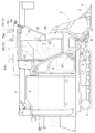
図1に示すように、左右一対のクローラ式走行装置1、1で支持された車体の前部に、刈取昇降シリンダ2にて横軸芯P1周りに駆動昇降自在に刈取部3が支持され、車体の前部の右側に運転部4が備えられ、車体の後部の左側に脱穀部5が備えられ、車体の後部の右側にグレンタンク6が備えられて、作業車の一例である自脱型のコンバインが構成されている。
As shown in FIG. 1, a cutting part 3 is supported at a front part of a vehicle body supported by a pair of left and right crawler
前記刈取部3は、先端部に付設された分草具7、穀稈の引き起こし装置8、引き起こした穀稈の株元を切断する刈刃9、先端側で刈取穀稈を受け取って脱穀部5のフィードチェーンに受け渡す縦搬送装置10等を備えている。
The cutting part 3 includes a
次に、動力伝達系を図8に示す。車体に搭載されたエンジンEの出力は、脱穀クラッチモータ11にて入切操作自在な脱穀クラッチ12を介して脱穀部に伝達されるとともに、無段変速装置13を介してミッション部14に伝達され、ミッション部40からの動力は左右両側のクローラ式走行装置1に供給される一方、刈取クラッチモータ15にて入切操作自在な刈取クラッチ16を介して刈取部3にも伝達される構成となっている。前記ミッション部14には、詳述はしないが、一方の走行装置1を他方の走行装置1より低速で駆動する緩旋回状態、一方の走行装置1を停止状態にするブレーキ旋回状態、一方の走行装置1を他方の走行装置1と逆向き状態に駆動する逆転旋回状態の夫々に切り換え自在な周知構成の旋回状態切換機構17が備えられている。この旋回状態切換機構17の切り換え操作は、後述する刈高操向レバー18の機体横幅方向への揺動操作により行われる構成となっている。
Next, the power transmission system is shown in FIG. The output of the engine E mounted on the vehicle body is transmitted to the threshing unit via the threshing clutch 12 that can be turned on and off by the threshing
前記無段変速装置13は、運転部4に備えられた手動操作式の変速レバー19にて手動で変速操作可能に連動連係されている。この変速レバー19は、運転部4における運転座席20の左側箇所に機体前後方向に揺動操作自在に設けられている。つまり、変速レバー19が前後操作範囲の中間部に位置する中立位置から前方側に操作されると無段変速装置13が前進方向での走行速度が増速し、変速レバー19が中立位置から後方側に操作されると無段変速装置13が後進方向での走行速度が増速する構成となっている。
The continuously
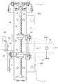
図2に示すように、運転部4の右側箇所には、刈取部3を昇降操作する刈取昇降指令具と車体を左右に旋回操作する旋回操作指令具とに兼用構成された十字操作式の刈高操向レバー18が設けられている。この刈高操向レバー18を後方側に揺動操作すると刈取部3が上昇し、前方側に揺動操作すると刈取部3が下降する構成となっている。
As shown in FIG. 2, a cross-operated type of cutting that is configured to serve both as a cutting up / down commanding tool for raising / lowering the cutting unit 3 and a turning operation commanding tool for turning the vehicle body left and right is provided at the right side of the
すなわち、図7に示すように、前記刈取昇降シリンダ2に対する圧油供給状態を切り換える油圧制御弁21、前記脱穀クラッチモータ11、前記刈取クラッチモータ15等の作動を制御するためのマイクロコンピュータを備えて構成される制御装置Hが備えられ、刈高操向レバー18を後方側に揺動操作するとオンする刈取上昇スイッチ22と、刈高操向レバー18を前方側に揺動操作するとオンする刈取下降スイッチ23とが設けられ、これらのスイッチの情報が制御装置Hに入力される。そして、制御装置Hは、刈取上昇スイッチ22がオンすると刈取昇降シリンダ2が上昇操作するように油圧制御弁21を切り換え、刈取下降スイッチ23がオンすると刈取昇降シリンダ2が下降操作するように油圧制御弁21を切り換えるように制御する。又、手動操作にて入切自在な脱穀入切スイッチ24及び刈取入切スイッチ25が設けられ、制御装置Hは、脱穀入切スイッチ24の操作状態により脱穀クラッチモータ11を切り換え制御し、刈取入切スイッチ25の操作状態により刈取クラッチモータ15を切り換えるように制御する。
That is, as shown in FIG. 7, a microcomputer for controlling the operation of the
連係構成について詳述はしないが、前記刈取操向レバー18と前記旋回状態切換機構17とが機械的に連係されており、刈高操向レバー18を左側に揺動操作すると車体が左旋回し、右側に揺動操作すると機体が右旋回するように、且つ、刈高操向レバー18の中立位置からの倒し角が大きくなるほど、前記緩旋回状態、前記ブレーキ旋回状態、及び、前記逆回転旋回状態に順次切り換わる、すなわち順次旋回力が大きくなるように旋回状態が切り換わるように構成されている。
Although not described in detail about the linkage configuration, the cutting
そして、刈高操向レバー18及び変速レバー19を運転座席20に着座した運転者により手動で操作する手動操縦状態と、刈高操向レバー18及び変速レバー19を夫々後述するような各別に備えられた駆動操作機構により操作することで予め設定した走行経路に沿って無人で走行可能な自動操縦状態とに切り換え可能に構成されている。
The cutting
説明を加えると、図2に示すように、刈高操向レバー18の機体後方側の近傍に位置させて、その刈高操向レバー18を機体横幅方向に操作する操向用の駆動操作機構26が備えられている。
図3〜図5に示すように、操向用の駆動操作機構26は、運転部4の座席前方側の操作パネル27Aに取付部としての連結具28Aを介してネジ止め固定されるフレーム部28に、操向用の電動モータ29(以下、操向用モータという)により回転駆動されるネジ軸30が機体横幅方向に沿う状態で回転自在に支持されており、このネジ軸30に螺合する雌ネジ部31を備えてネジ軸30の回転に伴ってネジ軸30の軸芯方向にスライド移動するスライド部材32が設けられている。
In addition, as shown in FIG. 2, as shown in FIG. 2, the driving operation mechanism for steering that is positioned in the vicinity of the rear side of the body of the cutting
As shown in FIGS. 3 to 5, the steering
スライド部材32にレバー保持部としての左右一対のレバー保持具33がボルト固定され、この左右一対のレバー保持具33は前記刈高操向レバー18に左右両側から接当作用する位置に備えられている。一対のレバー保持具33は、取り付け用の板体33Aとその板体33Aに溶接固定された補強用棒体33Bとで構成されている。
A pair of left and
又、図3に示すように、前記フレーム部28のネジ軸30の軸芯方向に沿って延びる箇所は断面略U字型に形成され、その断面略U字型の左右両側の上縁部に前記スライド部材32の被案内部32aが接当して、スライド部材32がネジ軸30の軸芯周りでの回動が阻止され且つ軸芯方向に沿って移動自在に案内される構成となっている。従って、枠体28の断面略U字型の左右両側の上縁部により、スライド部材32のネジ軸30の軸芯周りでの回動を阻止し且つ軸芯方向に沿ってスライド部材32を移動自在に案内する案内部Gが構成されている。
Further, as shown in FIG. 3, the portion extending along the axial direction of the
従って、前記操向用モータ29を回転駆動することにより前記ネジ軸30が回動操作されるに伴って、雌ネジ部31が螺進してスライド部材32がネジ軸30の軸芯方向に沿ってスライド移動することにより、レバー保持具33にて刈高操向レバー18を機体横幅方向に揺動操作可能な構成となっている。
Therefore, as the
前記操向用モータ29の出力軸34と前記ネジ軸30とは伝動チェーン35により連動連結されるが、モータ側スプロケット36がネジ軸側スプロケット37よりも大径に形成されており、操向用モータ29として減速機構を備えた汎用の安価な電動モータを用いるようにしながらネジ軸30を極力高速で回転させて迅速に操向操作を行えるようにしている。
The
又、前記フレーム部28の機体横幅方向中間の機体後方側箇所から上方に向かって延びる状態で設けられた支持部38に、前後軸芯周りで回転自在な検出用回転軸39を有するポテンショメータ40が備えられ、このポテンショメータ40の検出用揺動アーム41の揺動端部と前記スライド部材32に前後軸芯周りで回動自在に支持された中継リンク42の他端部とがピンを介して枢支連結され、スライド部材32のスライド移動に伴ってポテンショメータ40の検出用揺動アーム41が揺動する構成となっており、このポテンショメータ40によりスライド部材32のスライド位置すなわち、刈高操向レバー18の左右揺動操作量を検出することができるように構成されている。
In addition, a
図2に示すように、前記操向用モータ29は平面視で運転座席20の機体横幅方向の略中央位置に位置する状態で、且つ、側面視で後方側が上方に向くように斜め姿勢となるように配備されており、運転座席20に運転者が着座する場合に、運転中に足が操向用モータ29に干渉したり、乗り降りの際に邪魔にならないようにしている。
As shown in FIG. 2, the
次に、前記変速レバー19を操作するための変速用の駆動操作機構43について説明する。
この変速用の駆動操作機構43は、図2及び図6に示すように、運転部4における運転座席20の左側に位置するパネル部分に、その左側のパネル部分に備えられる各種の操作具に干渉しないように上方に位置させる状態で前後一対の縦フレーム44を介して取り付け固定されている。
Next, the
As shown in FIGS. 2 and 6, the
この変速用の駆動操作機構43は、主要部の構成は操向用の駆動操作機構26と同じであり、前記縦フレーム44に固定されたフレーム部45に電動モータ(以下、変速用モータという)46によって回転駆動されるネジ軸47が機体前後方向に沿う回転軸芯を備える状態で回転自在に支持されており、このネジ軸47に螺合する雌ネジ部48を備えてネジ軸47の回転に伴ってネジ軸47の軸芯方向にスライド移動するスライド部材49が設けられている。そして、このスライド部材49に前後方向に延びる操作ロッド50の後方側端部が連結用板体50Aを介して横軸芯周りで回動自在に枢支連結され、この操作ロッド50の前方側端部が変速レバー19に装着された連結具51に対して横軸芯周りで回動自在に枢支連結されている。
The
従って、変速用モータ46を回転駆動することにより前記ネジ軸47が回動操作されるに伴って、雌ネジ部48が螺進してスライド部材49がネジ軸47の軸芯方向に沿ってスライド移動することにより、操作ロッド50及び連結具51にて変速レバー19を機体前後方向に揺動操作可能な構成となっている。
Therefore, as the
前記変速用の駆動操作機構43は、前記操向用の駆動操作機構26と同様に、フレーム部45の前後方向中間の運転座席側箇所から上方に向かって延びる状態で設けられた支持部52に、機体横幅方向に沿う軸芯周りで回転自在な検出用回転軸53を有するポテンショメータ54が備えられ、このポテンショメータ54の検出用揺動アーム55の揺動端部と前記スライド部材49に横軸芯周りで回動自在に支持された中継リンク56の他端部とがピンを介して枢支連結され、スライド部材49のスライド移動に伴ってポテンショメータ54の検出用揺動アーム55が揺動する構成となっており、このポテンショメータ54によりスライド部材49のスライド位置すなわち、変速レバー19の揺動操作量を検出することができるように構成されている。
The
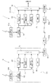
そして、このコンバインでは、GPS衛星58から送信される電波を受信して設定時間間隔で車体の位置情報を求めるGPS位置情報算出手段100と、車体の方位変位情報の一例としての縦軸芯周りでの車体の角速度変位を検出するジャイロ装置57と、前記GPS位置情報算出手段100にて求められる車体の位置情報及びジャイロ装置57にて検出される車体の方位変位情報に基づいて車体が設定経路に沿って走行するように操向制御する操向制御手段101とが備えられている。
In this combine, the GPS position information calculation means 100 that receives the radio wave transmitted from the
先ず、GPS位置情報算出手段100について説明する。
作業対象となる圃場の外部における地上側の適宜箇所に、その地点の重力方向に対して水平方向を東西及び南北方向で表した局地水平座標系E(東方向),N(北方向),H(地球中心からの高さ方向)において高精度に位置(上記座標系E,N,Hでの座標値)が判っている地上側の基準位置に設置されて、図10に示すように、少なくとも4個のGPS衛星58からのスペクトラム拡散変調された電波(搬送波信号)を受信するGPS基準局R(以後、単に基準局Rともいう)用のアンテナ59aと、このアンテナ59aの受信信号を処理して搬送波の位相情報を得るGPS受信機59と、そのGPS受信機59からの搬送波位相情報を車体側に向けて送信するための送信アンテナ60aを備えた地上側通信手段としての送受信機60とが設けられている。
First, the GPS position
A local horizontal coordinate system E (east direction), N (north direction), representing the horizontal direction in the east-west direction and the north-south direction with respect to the gravity direction of the point at an appropriate location on the ground side outside the field to be worked on, As shown in FIG. 10, it is installed at a ground-side reference position whose position (coordinate values in the coordinate systems E, N, and H) is known with high accuracy in H (the height direction from the center of the earth). An
又、車体側には、前記GPS衛星58からの電波(搬送波信号)を受信するGPS移動局I(以後、単に移動局Iともいう)用のアンテナ61aと、上記アンテナ61aの受信信号を処理して搬送波の位相情報を得るGPS受信機61と、前記地上側の送受信機60からの送信情報を受信するためのアンテナ62aを備えた車体側通信手段としての送受信機62とが設けられている。
On the vehicle body side, an
前記基準局R及び移動局Iの各GPS受信機59,61は、図11に示すように、同様の構成になるものであって、夫々のアンテナ59a,61aで受信した電波信号は、先ず高周波信号処理部63,64に入力して低周波数に変換される。その低周波数変換された信号は、C/Aコード解析部65、66にて衛星番号等が解読されるとともに、搬送波位相計測部67、68において、上記衛星番号に応じて作成されるC/Aコードと相関をとって搬送波が再生され、さらに内蔵した時計69、70にて設定時間間隔で搬送波の位相が計測される。同時に、C/Aコード解析部65、66からの情報に基づいて、航路メッセージ解読部71、72にて衛星位置情報等が判別される。そして、上記各部からの情報は、夫々の制御用のコンピュータ73、74に入力されて各基準局R及び移動局Iにおける搬送波位相情報が求められる。
As shown in FIG. 11, the
さらに、基準局R側コンピュータ73から出力された基準局Rでの搬送波位相情報が、前記地上側の送受信機60を経て送信アンテナ60aから送信され、車体側のアンテナ61aで受信され、送受信機62を経て移動局I側コンピュータ74に入力され,その移動局I側コンピュータ74において、基準局R及び移動局Iでの両搬送波位相情報に基づいて二重位相差情報が求められる。そして、上記GPS受信機61を利用して、移動局Iでの搬送波位相情報及び前記送受信機62が受信した基準局Rでの搬送波位相情報から求めた二重位相差情報に基づいて、前記基準位置つまり基準局Rに対する移動局Iつまり作業車Vの位置を所定時間間隔の時系列のGPS位置データとして求めるGPS位置情報算出手段100が構成されている。そして、このGPS受信機61で得られたGPS位置データが制御装置Hに入力されている。
Further, the carrier phase information at the reference station R output from the reference station
ここで、二重位相差情報について概略を説明すると、異なる2つのGPS衛星58からの各搬送波信号を2つの受信局(基準局R及び移動局I)夫々で受信して、各GPS衛星58ごとに対応する2つの位相差を求め、さらにこれら2つの位相差の差分をとったものを二重位相差と呼ぶ。これによって各GPS衛星58での送信信号の位相乱れの影響が除去されるとともに、各受信局の位相計測用の時計の同期ずれの影響が除去され、最終的に、衛星側及び受信局側での誤差の影響を少なくした精度のよい位相差情報が得られる。尚、後述の位置ベクトルrを求めるために、実際は、異なる4つのGPS衛星58からの各搬送波信号に基づいて、独立した3つの二重位相差が求められることになる。
Here, the outline of the double phase difference information will be described. Each carrier signal from two
前記GPS位置情報算出手段100による3つの二重位相差情報に基づく車体の位置検出について具体的に説明する。先ず最初に、コンバインの車体を前記局地水平座標系E,N,Hにおいて高精度に位置座標値が判っている地点に位置させ、移動局側及び基準局側の各GPS受信機59,61の受信情報から前記3つの二重位相差を計算し、基準局R及び車体間の相対位置が判っていることから上記二重位相差情報に含まれる搬送波波長の整数倍の不確定(整数値バイアス)を確定させる。次に、図9に示すように、車体を圃場内の任意の地点に移動させたときの3つの二重位相差情報より、基準局Rから車体への位置ベクトルrが求まり、基準局Rの基準位置と上記求めた位置ベクトルrとから、作業車Vの車体位置が判別される。前記GPS受信情報からの車体位置の検出は、所定時間(100msec)毎に時系列のGPS位置データとして求められる。
The position detection of the vehicle body based on the three double phase difference information by the GPS position information calculation means 100 will be specifically described. First, the combine body is positioned at a point where the position coordinate values are known with high accuracy in the local horizontal coordinate systems E, N, and H, and the
コンバインの車体には、上記したようなGPS衛星58から送信される電波を受信して設定時間間隔で車体の位置情報を求める構成とは別に、前記車体の方位変位情報の一例としての上下軸芯周りでの車体の角速度変位を検出する1軸型のジャイロ装置57が備えられている。
Apart from the configuration in which the vehicle body of the combiner receives the radio waves transmitted from the
そして、制御装置Hを利用して、GPS位置情報算出手段100にて求められる車体の位置情報及びジャイロ装置57にて検出される車体の方位変位情報に基づいて車体が設定経路に沿って走行するように操向制御する操向制御手段100が構成されている。
Then, using the control device H, the vehicle body travels along the set route based on the vehicle body position information obtained by the GPS position
前記設定経路Lは、地上側での位置座標(E,N,H座標系)を基準として定めたデータとして設定される。具体的には、作業対象となる圃場において、植立穀稈を植え付ける田植え作業を行うときに、田植え機に運転者が搭乗して手動にて運転操作しながら植え付け作業を行うのであるが、その田植え作業を実行する際に、田植え機に前記GPS位置情報算出手段100と同様なGPS位置情報算出手段を備えておき、前記田植え作業を行うときに、田植え機の車体の位置情報を田植え作業に伴って時系列的に求めて、記憶手段に読み込み記憶する処理を予め行っておく。
The set route L is set as data determined with reference to the position coordinates (E, N, H coordinate system) on the ground side. Specifically, when performing the rice planting work to plant the planted cereals in the field to be worked, the driver gets on the rice planting machine and performs the planting work while operating manually. When performing the rice planting work, the rice planting machine is provided with GPS position information calculating means similar to the GPS position
そして、その記憶情報を当該コンバインの制御装置Hにより読み込み、制御装置Hがその記憶情報から田植え作業にて植え付けられた植付け領域の情報や走行経路の情報等から刈取用の設定経路Lを作成するように構成されている。従って、制御装置Hが設定経路Lを作成する設定経路作成手段102を構成する。そのとき、田植え機による植え付け条数とコンバインの刈取条数が異なる場合には、その条数の違いに応じて経路を適宜補正することになる。 Then, the storage information is read by the control device H of the combine, and the control device H creates the setting route L for cutting from the information of the planting area planted in the rice planting work, the information of the travel route, and the like from the storage information. It is configured as follows. Accordingly, the control device H constitutes the setting route creating means 102 that creates the setting route L. At that time, in the case where the number of planting lines by the rice planting machine and the number of harvesting lines of the combine are different, the route is corrected as appropriate according to the difference in the number of lines.
前記設定経路について説明すると、図9に示すように、作業開始点stから作業を開始し、未刈穀稈列の端縁に沿って刈取作業を行う1つの作業行程の終端部に至ると、車体を略直交する方向に向きを換えて車体を走行させて次回の刈取作業を行う、いわゆる周り刈り形態で収穫作業を行うようになっており、このような走行を繰り返して、圃場F内の全ての植立穀稈を刈り取るように圃場の全範囲を走行することになる。刈取作業行程の終端部で旋回走行するときは、その刈取作業行程にて直進経路に沿って走行している状態から左側斜め方向に傾斜するように前進走行させて走行停止し、次に、前記直進経路と交差する次の直進経路の手前箇所に位置し且つ車体の前後方向が前記次の直進経路に沿う姿勢になるように後進走行させて走行停止し、その後、次の直進経路に沿って直進走行させる作業行程切換用の旋回走行、いわゆるαターン旋回走行を行うようになっている。従って、この作業行程切換用の旋回走行では、操向用モータ29の操作による車体の進行方向の向き変更操作だけでなく、変速用モータ46の操作により前進状態と後進状態との切り換えも合わせて行われる。
Describing the set route, as shown in FIG. 9, when the work starts from the work start point st and reaches the end of one work process in which the mowing work is performed along the edge of the uncut grain row, The harvesting work is carried out in a so-called surrounding trimming form in which the body is moved in a direction substantially orthogonal to the body and the next harvesting operation is performed, and such traveling is repeated, You will travel through the entire field to harvest all the planted cereals. When turning at the end portion of the cutting operation stroke, the vehicle is moved forward along the leftward oblique direction from the state of traveling along the straight traveling path in the cutting operation stroke, and then stopped. The vehicle travels backward so that the vehicle is positioned in front of the next straight path that intersects the straight path and the front-rear direction of the vehicle body is in a posture along the next straight path, and then stops traveling, and then along the next straight path. The vehicle is designed to perform a turn traveling for switching a work stroke for traveling straight ahead, that is, a so-called α-turn turning travel. Therefore, in the turning travel for switching the work stroke, not only the direction change operation of the vehicle body in the traveling direction by the operation of the
そして、この圃場で刈取作業を行うときは、モード設定スイッチ76を操作して自動走行モードに設定しておくと、上記したように設定した設定経路Lに沿って自動で走行させることができる。
つまり、自動走行モードが指令されると、制御装置Hは、前記GPS位置情報算出手段100にて求められる現在のGPS位置データ、及び、前記ジャイロ装置57により検出される車体の方位変化情報とに基づいて求められる現在時刻での前記車体の位置を前記地上側での位置座標(E,N,H座標系)を基準とする座標値として求めて、その座標値と前記走行経路Lを定めたデータとを比較して前記走行経路Lに対する前記車体の現在位置を求め、車体が設定経路Lに沿って走行するように操向制御する。具体的には、前記操向用モータ29を操作して車体を操向操作するのであるが、このとき、上記したような作業行程切換用の旋回走行を行うときは変速用モータ46を操作して前進走行状態や後進走行状態に切り換えることになる。又、制御装置Hは、このような車体の走行用の制御に加えて、刈取クラッチ16や脱穀クラッチ12の入切操作並びに刈取部3の昇降操作も合わせて自動で行うようになっている。
And when performing a cutting work in this field, if it sets to the automatic travel mode by operating the
That is, when the automatic travel mode is commanded, the control device H converts the current GPS position data obtained by the GPS position information calculation means 100 and the vehicle body direction change information detected by the
前記制御装置Hは、自動走行モードにおいて、車体を直進走行させるときは、GPS位置情報算出手段100により設定時間間隔毎に求めた車体の位置情報を設定時間が経過する間にジャイロ装置57にて検出される車体の方位変位情報に基づいて補正することで車体の現在位置を求め、車体の現在位置が設定経路Lに沿って直進走行するように操向制御する。
When the vehicle is traveling straight ahead in the automatic travel mode, the control device H uses the
そして、ジャイロ装置57にて車体の方位変位情報が適正に検出されているジャイロ情報適正状態であるか車体の方位変位情報が適正に検出されていないジャイロ情報不適正状態であるかを判別するジャイロ情報判別手段103が備えられ、操向制御手段101が、前記ジャイロ情報判別手段103により前記ジャイロ情報適正状態であることが検出されると、GPS位置情報算出手段100にて求められる車体の位置情報及びジャイロ装置57にて検出される車体の方位変位情報に基づいて操向制御し、且つ、ジャイロ情報判別手段103により前記ジャイロ情報不適正状態であることが検出されると、GPS位置情報算出手段100にて求められた車体の位置情報のみに基づいて操向制御するように構成されている。
The
又、ジャイロ情報判別手段103が、操向制御手段101にて車体が設定経路のうちの直線状経路部分に沿って走行するように操向制御されているときに、ジャイロ装置57にて検出される車体の方位変位量が設定許容量を超える検出異常状態であると判別する頻度が設定頻度より大であれば、ジャイロ情報不適正状態であると判別するように構成されている。
Further, the gyro information discriminating means 103 is detected by the
そして、操向制御手段101は、車体が設定経路Lのうちの曲線状経路部分に沿って走行するように操向制御するときには、ジャイロ情報判別手段103によりジャイロ情報適正状態であることが検出されている場合は、ジャイロ装置57にて検出される車体の方位変位情報のみに基づいて操向制御するように構成されている。
When the steering control means 101 performs steering control so that the vehicle body travels along the curved route portion of the set route L, the gyro information determination means 103 detects that the gyro information is in an appropriate state. The steering control is performed based only on the azimuth displacement information of the vehicle body detected by the
又、ジャイロ情報判別手段103によりジャイロ情報不適正状態であることが検出されたのちにGPS位置情報算出手段100にて車体の位置情報が適正に求められていない状態になると車体の走行を停止させる非常停止手段104が備えられている。
Further, after the gyro information discriminating means 103 detects that the gyro information is in an inappropriate state, the GPS position
前記操向制御手段101は、車体が設定経路Lのうちの直線状経路部分から曲線状経路部分を経由して再度直線状経路部分に沿って走行するときに、GPS位置情報算出手段100の検出情報に基づいて車体が曲線状経路部分における旋回走行を開始してから旋回走行を終了するまでの間の車体の方位変位量を求めるように構成され、且つ、車体が曲線状経路部分における旋回走行を開始してから旋回走行を終了するまでの間にジャイロ装置57の検出情報に基づいて求められる車体の方位変位量とGPS位置情報算出手段100の検出情報に基づいて求めた車体の方位変位量との差が設定許容量を越えていることを判別すると、警報手段を作動させる警報作動処理を実行するように構成されている。
The steering control unit 101 detects the GPS position
前記GPS位置情報算出手段100が、GPS衛星から送信される電波を適正に受信している適正受信モード、電波を受信しているものの車体の位置情報が不安定である不安定受信モード及び電波を受信できていない受信不能モードのいずれかに切り換わるように構成され、そのモードの切り換わりに応じて互いに異なる表示形態となる判別状態表示手段78が備えられている。 The GPS position information calculation means 100 receives an appropriate reception mode in which radio waves transmitted from GPS satellites are properly received, an unstable reception mode in which the position information of the vehicle body is unstable although radio waves are received, and radio waves. It is configured to switch to any of the unreceivable modes that cannot be received, and is provided with a discrimination state display means 78 that has different display modes depending on the mode switching.
前記各モードについて説明を加えると、4個のGPS衛星58からの電波が全て良好に受信されているときは前記適正受信モードとなり、この適正受信モードでは、計測誤差が±2cm程度で高精度で位置を計測できる。又、4個のGPS衛星58のうち、いずれかのものの電波が適正に受信されていない状態、例えば、GPS衛星58からの電波を直接アンテナ61aにて受信する直接受信波と、GPS衛星58からの電波が地面にて一旦反射したのちにアンテナ61aにて受信する間接受信波とがあるような場合には車体の位置情報として2つの検出値が同時に求められる等、動作が不安定になるおそれがある。このような状態が不安定受信モードであり、この不安定受信モードでは計測誤差が±1m程度であり計測精度が悪くなる。そして、GPS衛星58からの電波が受信できていない場合には前記受信不能モードと判別する。このような状態になるのは、例えば、他の建物等の周囲の障害物によってGPS衛星からの電波が遮られるような場合がある。このときは車体の位置の計測はできないことになる。
In addition to the explanation of each mode, when all the radio waves from the four
前記判別状態表示手段78は、図1に示すように、車体の運転部4を覆うキャビンの上部に立設する状態で備えられ、圃場の外部の畦から目視することが可能なように見やすい2つの表示ランプ79、80にて構成されている。このGPS用の表示ランプ79は、GPS位置情報算出手段100が前記適正受信モードに切り換わると緑色表示ランプ79aが点灯し、不安定受信モードに切り換わると黄色表示ランプ79bが点灯し、前記受信不能モードに切り換わると赤色表示ランプ79cが点灯するようになっており、異なる表示内容としての表示色が切り換わるように構成されている。又、ジャイロ用の表示ランプ80はジャイロ装置57の検出状態が異常であれば青色に点灯する青色表示ランプに構成され、正常であれば消灯するように構成されている。
As shown in FIG. 1, the discrimination state display means 78 is provided in a state of standing on an upper part of a cabin that covers the driving
図9に示すように、作業対象となる圃場の外周部には、コンバインが自動走行しているときに、圃場の外部に脱出して車体が暴走することが無いように、車体が圃場から外方に向けて脱出しようすることを検出する光式の車体検出装置81が設けられ、この光式の車体検出装置81は、車体が圃場から後記するレーザー光により作成される境界線を越えて外方に向けて移動しようとすることを検出すると、車体に備えられた非常用受信機82に無線送信によって非常停止信号を送信して、車体を停止させるように構成されている。
As shown in FIG. 9, on the outer periphery of the field to be worked, when the combine is automatically traveling, the vehicle body is out of the field so that it does not escape from the field and the vehicle body runs out of control. An optical vehicle
前記光式の車体検出装置81は、圃場の外周縁に沿ってレーザー光を発光する発光装置81Aが対角に位置する2箇所の角部に夫々設けられ、他の2箇所の角部にレーザー光を受光する受光装置81Bが備えられ、受光装置81Bはレーザー光が受信されなくなると、その受信装置81Bに備えられた無線送信機81Cにより非常用受信機82に無線送信によって非常停止信号を送信する構成となっている。
In the optical vehicle
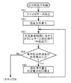
次に、図12〜図15に示すフローチャートに基づいて制御装置Hの制御動作について説明する。尚、畦から作業開始地点stまでは手動操縦により又は他の運搬車両により車体を移動させる。そして、この制御は、圃場の外部にいる管理者が図示しない無線通信装置にて開始を指令することで処理を開始する構成となっている。又、この処理は単位時間(例えば、20msec)毎に繰り返し実行することになる。 Next, the control operation of the control device H will be described based on the flowcharts shown in FIGS. Note that the vehicle body is moved from the heel to the work start point st by manual operation or by another transport vehicle. And this control becomes a structure which starts a process by instruct | indicating a start with the radio | wireless communication apparatus which is not shown in figure by the manager who is outside the field. This process is repeatedly executed every unit time (for example, 20 msec).
図12に示すように、制御モードが経路設定モードであれば、上記したような記憶情報に基づく経路設定処理を実行する(ステップ1、2)。自動走行モードでは、先ず作業開始処理を実行する(ステップ3)。すなわち、脱穀クラッチ12及び刈取クラッチ16を入り操作し、変速レバー19を刈取用の前進速度まで変速して刈取部3を下降させ直進走行を開始する。このような直進走行を開始したのちは、直進用走行制御を実行することになる(ステップ4)。
As shown in FIG. 12, if the control mode is the route setting mode, the route setting process based on the stored information as described above is executed (
次に、図13及び図14を参照しながら直進用走行制御について説明する。
前記GPS位置情報算出手段100による算出されるGPS位置データを設定時間(100msec)が経過する毎に読み込み(ステップ41、42)、前記GPS位置データにより車体の位置を算出する(ステップ43)。又、当該処理を実行する単位時間(20msec)毎にジャイロ装置57の検出情報を読み込み、その検出情報に基づいて前回の検出方位からの車体の方位変位量を算出する(ステップ44、45)。
Next, the straight traveling control will be described with reference to FIGS. 13 and 14.
The GPS position data calculated by the GPS position
そして、前記ジャイロ装置57の検出情報が異常であるか否かを判別する(ステップ46)。すなわち、直進走行するように操向制御されているとき、具体的には、前記ポテンショメータ40にて検出される刈高操向レバー18の位置が中立位置にあるときに、ジャイロ装置57にて検出される車体の方位変位量が設定許容量未満である場合には、車体の方位変位情報がいずれも適正に検出されている適正検出状態であると判別し、ジャイロ装置57にて検出される車体の方位変位量が設定許容量を超えている場合には、車体の方位変位情報が適正に得られていない不適正検出状態であると判別する。
Then, it is determined whether or not the detection information of the
前記ジャイロ装置57が適正な検出状態であるときは、そのときGPS位置情報算出手段100が前記適正受信モードであれば適正検出状態であると判別してGPS用表示ランプ79の緑色表示ランプ79aを点灯させる(ステップ47、48)。GPS位置情報算出手段100が前記不安定受信モードであれば不適正検出状態であると判別してGPS用表示ランプ79の黄色表示ランプ79bを点灯させる(ステップ49)。GPS位置情報算出手段100が前記受信不能モードであれば不適正検出状態であると判別してGPS用表示ランプ79の赤色表示ランプ79cを点灯させる(ステップ50)。又、前記不適正検出状態が設定時間(0.5秒間)以上継続しているときは、それ以上の走行は危険であるから車体を非常停止させ、赤色表示ランプ79cを点滅表示する(ステップ52、54)。
When the
GPS位置情報算出手段100が前記適正受信モードであれば、設定時間毎に前記GPS位置データにより算出される車体の位置情報とジャイロ装置57の検出情報とに基づいて車体の現在位置を求める(ステップ51)。
If the GPS position
この位置の求め方について説明を加えると、図16に示すように、前記GPS位置データにより車体の位置を算出する処理は設定時間(100msec)毎に行われ、ジャイロ装置57による方位変位量を算出する処理は単位時間(20msec)毎に行われるが、前記GPS位置データにより求められた車体の位置GP1,GP2‥を基にしてその位置から方位変位量データJD並びにそのときの車速の情報から求められる位置変位量を加味して単位時間毎に現在位置を求めるのである。
説明を加えると、上述したように、前記方位変位量データJDは単位時間(20msec)毎に得られるが、基となる車体の位置GP1,GP2‥は、現在時刻よりも100msec前に計測された位置である。そこで、この位置情報が得られる100msec経過毎に、基となる位置情報(100msec前のデータ)を今回得られた位置データにて補正することで、正確な位置情報を得ることができるようになっている。
尚、車速の情報は、前記変速用の駆動操作機構43におけるポテンショメータ54による変速レバー19の操作位置の情報により求めることができる。
As shown in FIG. 16, how to obtain the position is described. The process of calculating the position of the vehicle body based on the GPS position data is performed every set time (100 msec), and the amount of azimuth displacement by the
When the explanation is added, as described above, the azimuth displacement data JD is obtained every unit time (20 msec), but the positions GP1, GP2,... Of the base body are measured 100 msec before the current time. Position. Thus, every 100 msec after this position information is obtained, the position information that is the basis (data before 100 msec) is corrected with the position data obtained this time, so that accurate position information can be obtained. ing.
The vehicle speed information can be obtained from information on the operation position of the
そして、上記したようにして求められる車体の現在位置が設定経路L上に位置するように、操向用モータ29を制御する(ステップ55)。例えば、車体の現在位置が設定経路Lから設定量を越えて大きく離間しているときは、前記ブレーキ旋回状態に対応する操作位置を目標位置として刈高操向レバー18を操作するように操向用モータ29を制御し、車体の現在位置が設定経路Lからの離間距離が設定量未満であるときは、前記緩旋回状態に対応する操作位置を目標位置として刈高操向レバー18を操作するように操向用モータ29を制御する。
Then, the
前記GPS位置情報算出手段100が前記不安定受信モード又は前記受信不能モードである状態が前記設定時間以上継続していなければ、しかも、後述するようなジャイロ牽制モードでなければ、前記不安定受信モードや前記受信不能モードになっている間だけ、前記GPS位置データを採用せずに、前記ジャイロ装置57の検出情報により車体の現在位置を求めて、その情報に基づいて車体が設定経路に沿って走行するように操向用モータ29を制御する(ステップ52A、53、55)。
If the GPS position information calculation means 100 is not in the unstable reception mode or the incapable reception mode for more than the set time and is not a gyro check mode as described later, the unstable reception mode The GPS position data is not used only during the reception disabled mode, and the current position of the vehicle body is obtained from the detection information of the
又、ステップ46にて前記ジャイロ装置57が不適正な検出状態であることが判別すると、ジャイロ用表示ランプとしての青色ランプ80を点灯させて異常を表示する(ステップ56)。そして、前記ジャイロ装置57が不適正な検出状態であると判別した回数が連続して設定回数以上発生すると、ジャイロ装置57の情報を用いないジャイロ情報不適正状態としてのジャイロ牽制モードに切り換えて、青色表示ランプ80を点滅表示する(ステップ57、58、59)。又、このように検出異常状態であればジャイロ装置57の情報が使用できないので、前記GPS位置データにより算出した車体の現在位置のみに基づいて操向制御する(ステップ60、55)。
If it is determined in
前記ジャイロ装置57が不適正な検出状態であると判別した回数が連続して設定回数以上発生していない場合には、GPS位置情報算出手段100が前記適正受信モードであれば緑色表示ランプ79aを点灯させ(ステップ61、62)、ジャイロ装置のデータを用いないでGPS位置情報のみに基づいて車速の位置を求めて、車体の位置が設定経路Lに沿って走行するように操向用モータ29を制御する(ステップ65)。
If the number of times that the
又、GPS位置情報算出手段100が前記不安定受信モードであれば黄色表示ランプ79bを点灯させ(ステップ63)、GPS位置情報算出手段100が前記受信不能モードであれば赤色表示ランプ79cを点灯させる(ステップ64)。前記不適正検出状態が設定時間(0.5秒間)以上継続しているときは、それ以上の走行は危険であるから車体を非常停止させ、赤色表示ランプ79cを点滅表示する(ステップ66、54)。前記不適正検出状態が設定時間(0.5秒間)より短い間はそのときの状態を維持する。コンバインではこのような短時間の間に大きく向き変更することは少ないと考えられるから、短時間の間はそのままの操向状態で走行を継続するのである。
If the GPS position
刈取作業の対象となる直進走行経路の終点に到達すると、刈取作業を終了し、次の刈取作業対象となる直進走行経路に向けて車体を約90度旋回させる旋回箇所に至ったことを判別すると、旋回用走行制御を実行する(ステップ5〜8)。
When reaching the end point of the straight traveling route that is the target of the cutting operation, the cutting operation is terminated, and it is determined that the vehicle has reached a turning point that turns the vehicle body about 90 degrees toward the straight traveling route that is the next target of the cutting operation. Then, running control for turning is executed (
次に、図15を参照しながら旋回用走行制御について説明する。
前記ジャイロ牽制モードでなければ、ジャイロ装置57の検出情報を読み込み、その検出情報から前回の検出方位からの車体の方位変位量を算出して車体の現在方位を算出する(ステップ81、82、83)。そのジャイロ装置57の検出情報により前回の直進走行経路に対して約90度傾斜した次回の直進走行経路に向かうように作業行程切換用の旋回操作を実行する(ステップ86)。しかし、前記ジャイロ牽制モードであれば、旋回走行開始前に前記GPS位置データにより算出された車体の現在位置及び現在方位の情報により、前回の直進走行経路に対して約90度傾斜した次回の直進走行経路に沿う目標方位に向かうように上述したような旋回操作を実行する(ステップ84、86)。
Next, turning traveling control will be described with reference to FIG.
If it is not the gyro check mode, the detection information of the
旋回走行が終了した後に、その旋回走行状態において、GPS位置情報算出手段100の検出情報に基づいて車体が旋回走行を開始してから旋回走行を終了するまでの間の車体の方位変位量を求め、且つ、車体が旋回走行を開始してから旋回走行を終了するまでの間にジャイロ装置57の検出情報に基づいて求められる車体の方位変位量と、GPS位置情報算出手段100の検出情報に基づいて求めた車体の方位変位量との差が設定許容量を越えていることを判別すると、赤色表示ランプ79c及び青色表示ランプ80を夫々点滅表示して警報作動を行うようになっている(ステップ10、11)。従って、赤色表示ランプ79c及び青色表示ランプ80が警報手段を構成する。
After the cornering is finished, in the cornering state, the azimuth displacement amount of the body from the start of the cornering to the end of the cornering is obtained based on the detection information of the GPS position information calculation means 100. In addition, based on the azimuth displacement amount of the vehicle body that is obtained based on the detection information of the
説明を加えると、GPS位置情報算出手段100の検出情報により、旋回走行する前の直進走行状態において設定時間毎に求められる車体の位置情報により車体がどの方位に向けて走行したかが判り、又、旋回走行した後の直進走行状態においても設定時間毎に求められる車体の位置情報により車体がどの方位に向けて走行したかが判るので、それらの方位の差から車体の方位変位量を求めることができるので、ジャイロ装置57の検出情報に基づいて求められる方位変位量とを比較することで検出情報の異常を検出できるのである。
When the explanation is added, the detection information of the GPS position information calculation means 100 can determine in which direction the vehicle body has traveled based on the vehicle body position information obtained for each set time in the straight traveling state before turning. In the straight traveling state after turning, the vehicle body position information obtained at every set time can be used to determine which direction the vehicle body has traveled. Therefore, the abnormality of the detection information can be detected by comparing with the amount of azimuth displacement obtained based on the detection information of the
そして、その後は、次回の直進走行経路に沿って刈取作業を実行するのであり、以降、このような処理を繰り返して設定経路に沿って車体を走行させながら圃場内の刈取作業が全て終了するまで処理を実行することになる。 After that, the mowing work is executed along the next straight traveling route, and thereafter, the process is repeated until the mowing work in the field is completed while the vehicle body is driven along the set route. Processing will be executed.
〔別実施形態〕
(1)上記実施形態では、前記ジャイロ情報判別手段が、ジャイロ装置にて検出される車体の方位変位量が設定許容量を超える検出異常状態であると判別する頻度が設定頻度より大であるか否かを判別する構成として、検出異常状態であると判別する回数が連続して設定回数以上であれば、前記ジャイロ情報不適正状態であると判別するようにしたが、このような構成に代えて、前記検出異常状態であると判別する回数が設定時間内に第1設定回数以上となる状態が第2設定回数以上繰り返し発生する検出異常状態であると判別する構成としてもよい。
[Another embodiment]
(1) In the above-described embodiment, is the frequency at which the gyro information determination means determines that the vehicle body azimuth displacement detected by the gyro device is in a detection abnormal state exceeding a set allowable amount greater than the set frequency? As a configuration for determining whether or not the detection abnormal state is present, if the number of times that the detection abnormal state is continuously set is equal to or greater than the set number of times, it is determined that the gyro information is in an inappropriate state. In addition, a configuration may be adopted in which it is determined that a state in which the number of times that the detection abnormal state is detected is equal to or greater than the first set number of times within a set time is a detection abnormal state that repeatedly occurs for the second set number of times.
(2)上記実施形態では、前記車体が旋回走行を開始してから旋回走行を終了するまでの間に前記ジャイロ装置の検出情報に基づいて求められる前記車体の方位変位量と、前記GPS位置情報算出手段の検出情報に基づいて求めた前記車体の方位変位量との差が設定許容量を越えていることを判別すると、警報手段を作動させる警報作動処理を実行するように構成したが、このような警報作動処理を実行しない構成としてもよい。 (2) In the above-described embodiment, the azimuth displacement amount of the vehicle body obtained based on the detection information of the gyro device after the vehicle body starts turning and ends turning, and the GPS position information When it is determined that the difference from the azimuth displacement amount of the vehicle body obtained based on the detection information of the calculation means exceeds the set allowable amount, an alarm activation process for operating the alarm means is executed. It is good also as a structure which does not perform such an alarm action process.
(3)上記実施形態では、設定経路のうち直進状経路部分を走行するように車体を操向制御するときに、前記ジャイロ情報判別手段が、ジャイロ装置にて検出される車体の方位変位量が設定許容量を超える検出異常状態であると判別したときにだけ、前記GPS位置データにより算出した車体の現在位置及び現在方位の情報のみに基づいて操向制御する構成としたが、直進状経路部分を走行するように車体を操向制御するときには、ジャイロ装置が検出異常状態でなくても、前記GPS位置データにより算出した車体の現在位置及び現在方位の情報のみに基づいて操向制御する構成としてもよい。 (3) In the above-described embodiment, when the vehicle body is steered so as to travel along the straight path portion of the set route, the gyro information determining means determines that the azimuth displacement amount of the vehicle body detected by the gyro device is Only when it is determined that the detection abnormal state exceeds the set allowable amount, the steering control is performed based only on the current position and current direction information of the vehicle body calculated from the GPS position data. When steering the vehicle to travel the vehicle, even if the gyro device is not in an abnormal detection state, the steering control is based only on the current position and current direction information of the vehicle calculated from the GPS position data. Also good.
(4)上記実施形態では、前記設定経路に沿って直進走行するように操向制御されているときに、前記GPS位置情報算出手段の検出情報と前記ジャイロ装置の検出情報に車体の現在位置を求めるようにしたが、前記各検出情報に基づいて、前記車体の現在位置及び車体の現在方位を夫々検出してその情報に基づいて操向制御するよう構成するものでもよい。 (4) In the above-described embodiment, when steering control is performed so that the vehicle travels straight along the set route, the current position of the vehicle body is determined based on the detection information of the GPS position information calculation unit and the detection information of the gyro device. However, it may be configured to detect the current position of the vehicle body and the current direction of the vehicle body based on the detection information and to perform steering control based on the information.
(5)上記実施形態では、左右一対のクローラ式走行装置を備える作業車であって、旋回走行するときに、左右走行装置の速度差にて旋回を行い、作業行程切換用の旋回走行を行うときは前進走行と後進走行とを繰り返す構成としたが、このような構成に代えて、車輪式の作業車であって、車輪の向きを変化させて操向する作業車であってもよく、その場合には、操向制御手段が、車輪の向きを変更させる操向用のアクチュエータだけを操作して車体を操向させる構成とし、走行速度を変更しない構成としてもよい。 (5) In the above embodiment, the work vehicle is provided with a pair of left and right crawler type travel devices, and when making a turn, the turn is performed at a speed difference between the left and right travel devices, and a turn travel for switching the work stroke is performed. Sometimes, it was configured to repeat forward travel and reverse travel, but instead of such a configuration, it may be a wheel type work vehicle, which may be a work vehicle that steers by changing the direction of the wheels, In that case, the steering control means may be configured to operate only the steering actuator that changes the direction of the wheel to steer the vehicle body and not to change the traveling speed.
(6)上記実施形態では、赤色表示ランプ79c及び青色表示ランプ80が警報手段を兼用する構成としたが、専用の警報ランプを備える構成としてもよい。
(6) In the above embodiment, the
(7)上記実施形態では、作業車がコンバインである場合について説明したが、本発明は、例えば田植え用作業車、農用トラクター等、各種作業車にも適用できる。 (7) Although the case where the work vehicle is a combine has been described in the above embodiment, the present invention can also be applied to various work vehicles such as a rice planting work vehicle and an agricultural tractor.
57 ジャイロ装置
58 GPS衛星
79c、80 警報手段
100 GPS位置情報算出手段
101 操向制御手段
103 ジャイロ情報判別手段
104 非常停止手段
57
Claims (5)
前記ジャイロ装置にて前記車体の方位変位情報が適正に検出されているジャイロ情報適正状態であるか前記車体の方位変位情報が適正に検出されていないジャイロ情報不適正状態であるかを判別するジャイロ情報判別手段が備えられ、
前記操向制御手段が、
前記ジャイロ情報判別手段により前記ジャイロ情報適正状態であることが検出されると、前記GPS位置情報算出手段にて求められる車体の位置情報及び前記ジャイロ装置にて検出される前記車体の方位変位情報に基づいて操向制御し、且つ、
前記ジャイロ情報判別手段により前記ジャイロ情報不適正状態であることが検出されると、前記GPS位置情報算出手段にて求められた前記車体の位置情報のみに基づいて操向制御するように構成されている作業車の走行制御装置。 GPS position information calculating means for receiving a radio wave transmitted from a GPS satellite and obtaining vehicle body position information at set time intervals, a gyro device for detecting azimuth displacement information of the vehicle body, and the GPS position information calculating means A steering control means for controlling steering so that the vehicle body travels along a set route based on vehicle body position information and azimuth displacement information detected by the gyro device. A vehicle travel control device,
A gyro that determines whether the gyro information is properly detected by the gyro device and the gyro information is not properly detected. Information discriminating means is provided,
The steering control means is
When the gyro information determining means detects that the gyro information is in an appropriate state, the position information of the vehicle body obtained by the GPS position information calculating means and the azimuth displacement information of the vehicle body detected by the gyro device are used. Steering control based on, and
When the gyro information determination unit detects that the gyro information is in an inappropriate state, the steering control is performed based only on the position information of the vehicle body obtained by the GPS position information calculation unit. A traveling vehicle travel control device.
前記操向制御手段にて前記車体が前記設定経路のうちの直線状経路部分に沿って走行するように操向制御されているときに、前記ジャイロ装置にて検出される前記車体の方位変位量が設定許容量を超える検出異常状態であると判別する頻度が設定頻度より大であれば、前記ジャイロ情報不適正状態であると判別するように構成されている請求項1記載の作業車の走行制御装置。 The gyro information discriminating means is
The azimuth displacement amount of the vehicle body detected by the gyro device when the vehicle body is steered so that the vehicle body travels along a straight path portion of the set route. The traveling of the work vehicle according to claim 1, wherein if the frequency at which it is determined that the detection abnormal state exceeds the set allowable amount is greater than the set frequency, it is determined that the gyro information is in an inappropriate state. Control device.
前記車体が前記設定経路のうちの曲線状経路部分に沿って走行するように操向制御するときには、前記ジャイロ情報判別手段により前記ジャイロ情報適正状態であることが検出されている場合は、前記ジャイロ装置にて検出される前記車体の方位変位情報のみに基づいて操向制御するように構成されている請求項1又は2記載の作業車の走行制御装置。 The steering control means is
When steering control is performed so that the vehicle body travels along a curved path portion of the set route, if the gyro information determination unit detects that the gyro information is in an appropriate state, the gyro information The traveling control device for a work vehicle according to claim 1 or 2, wherein the steering control is performed based on only the azimuth displacement information of the vehicle body detected by the device.
前記車体が前記設定経路のうちの直線状経路部分から曲線状経路部分を経由して再度直線状経路部分に沿って走行するときに、前記GPS位置情報算出手段の検出情報に基づいて前記車体が前記曲線状経路部分における旋回走行を開始してから旋回走行を終了するまでの間の前記車体の方位変位量を求めるように構成され、且つ、
前記車体が前記曲線状経路部分における旋回走行を開始してから旋回走行を終了するまでの間に前記ジャイロ装置の検出情報に基づいて求められる前記車体の方位変位量と前記GPS位置情報算出手段の検出情報に基づいて求めた前記車体の方位変位量との差が設定許容量を越えていることを判別すると、警報手段を作動させる警報作動処理を実行するように構成されている請求項1〜4のいずれか1項に記載の作業車の走行制御装置。 The steering control means is
When the vehicle body travels again along the linear route portion from the linear route portion of the set route via the curved route portion, the vehicle body is based on the detection information of the GPS position information calculating means. It is configured to obtain the azimuth displacement amount of the vehicle body from the start of turning on the curved path portion to the end of turning, and
The azimuth displacement amount of the vehicle body obtained based on the detection information of the gyro device and the GPS position information calculating means between the start of the vehicle body turning in the curved path portion and the end of the vehicle turning. The alarm activation process for activating the alarm means is executed when it is determined that the difference from the azimuth displacement amount of the vehicle body obtained based on the detection information exceeds a set allowable amount. 5. The traveling control device for a work vehicle according to any one of 4 above.
Priority Applications (1)
| Application Number | Priority Date | Filing Date | Title |
|---|---|---|---|
| JP2008088353A JP2009245002A (en) | 2008-03-28 | 2008-03-28 | Travel controller for working vehicle |
Applications Claiming Priority (1)
| Application Number | Priority Date | Filing Date | Title |
|---|---|---|---|
| JP2008088353A JP2009245002A (en) | 2008-03-28 | 2008-03-28 | Travel controller for working vehicle |
Publications (1)
| Publication Number | Publication Date |
|---|---|
| JP2009245002A true JP2009245002A (en) | 2009-10-22 |
Family
ID=41306843
Family Applications (1)
| Application Number | Title | Priority Date | Filing Date |
|---|---|---|---|
| JP2008088353A Pending JP2009245002A (en) | 2008-03-28 | 2008-03-28 | Travel controller for working vehicle |
Country Status (1)
| Country | Link |
|---|---|
| JP (1) | JP2009245002A (en) |
Cited By (9)
| Publication number | Priority date | Publication date | Assignee | Title |
|---|---|---|---|---|
| CN101833334A (en) * | 2010-02-09 | 2010-09-15 | 北京农业信息技术研究中心 | Tractor automatic navigation control system and method thereof |
| JP2014186723A (en) * | 2013-02-19 | 2014-10-02 | Muroran Institute Of Technology | Automatic plant harvesting machine, automatic plant harvesting program, and automatic plant harvesting method |
| JP2017123804A (en) * | 2016-01-13 | 2017-07-20 | 株式会社クボタ | Work vehicle |
| WO2018135234A1 (en) | 2017-01-20 | 2018-07-26 | 株式会社クボタ | Work vehicle |
| KR20180098525A (en) | 2015-12-25 | 2018-09-04 | 가부시끼 가이샤 구보다 | Working car |
| JP2018165922A (en) * | 2017-03-28 | 2018-10-25 | ヤンマー株式会社 | Remote monitoring system for agricultural machine |
| KR20190077060A (en) * | 2017-03-09 | 2019-07-02 | 얀마 가부시키가이샤 | Path generation system |
| JP2020185994A (en) * | 2020-07-28 | 2020-11-19 | 株式会社クボタ | Work vehicle |
| JP7336314B2 (en) | 2019-08-27 | 2023-08-31 | 三菱マヒンドラ農機株式会社 | work vehicle |
Citations (7)
| Publication number | Priority date | Publication date | Assignee | Title |
|---|---|---|---|---|
| JPH09145367A (en) * | 1995-11-27 | 1997-06-06 | Nosakubutsu Seiiku Kanri Syst Kenkyusho:Kk | Work management system for working truck |
| JPH10246642A (en) * | 1996-11-22 | 1998-09-14 | Zexel:Kk | Navigation method for conducting angular velocity correction in use of directional detecting sensor |
| JPH10311735A (en) * | 1997-04-02 | 1998-11-24 | Caterpillar Inc | Method for monitoring of integrality of gps and inu integrated system |
| JPH11295101A (en) * | 1998-04-10 | 1999-10-29 | Toshiba Corp | Position display device, position display method and record medium |
| JP2005122530A (en) * | 2003-10-17 | 2005-05-12 | Matsushita Electric Ind Co Ltd | Self-traveling device and program therefor |
| JP2008035695A (en) * | 2006-06-30 | 2008-02-14 | East Japan Railway Co | Protection radio automatic alarm system |
| JP2008035696A (en) * | 2006-06-30 | 2008-02-14 | East Japan Railway Co | Protection radio automatic alarm system |
-
2008
- 2008-03-28 JP JP2008088353A patent/JP2009245002A/en active Pending
Patent Citations (7)
| Publication number | Priority date | Publication date | Assignee | Title |
|---|---|---|---|---|
| JPH09145367A (en) * | 1995-11-27 | 1997-06-06 | Nosakubutsu Seiiku Kanri Syst Kenkyusho:Kk | Work management system for working truck |
| JPH10246642A (en) * | 1996-11-22 | 1998-09-14 | Zexel:Kk | Navigation method for conducting angular velocity correction in use of directional detecting sensor |
| JPH10311735A (en) * | 1997-04-02 | 1998-11-24 | Caterpillar Inc | Method for monitoring of integrality of gps and inu integrated system |
| JPH11295101A (en) * | 1998-04-10 | 1999-10-29 | Toshiba Corp | Position display device, position display method and record medium |
| JP2005122530A (en) * | 2003-10-17 | 2005-05-12 | Matsushita Electric Ind Co Ltd | Self-traveling device and program therefor |
| JP2008035695A (en) * | 2006-06-30 | 2008-02-14 | East Japan Railway Co | Protection radio automatic alarm system |
| JP2008035696A (en) * | 2006-06-30 | 2008-02-14 | East Japan Railway Co | Protection radio automatic alarm system |
Cited By (16)
| Publication number | Priority date | Publication date | Assignee | Title |
|---|---|---|---|---|
| CN101833334A (en) * | 2010-02-09 | 2010-09-15 | 北京农业信息技术研究中心 | Tractor automatic navigation control system and method thereof |
| JP2014186723A (en) * | 2013-02-19 | 2014-10-02 | Muroran Institute Of Technology | Automatic plant harvesting machine, automatic plant harvesting program, and automatic plant harvesting method |
| KR20180098525A (en) | 2015-12-25 | 2018-09-04 | 가부시끼 가이샤 구보다 | Working car |
| JP2017123804A (en) * | 2016-01-13 | 2017-07-20 | 株式会社クボタ | Work vehicle |
| KR20220078721A (en) | 2017-01-20 | 2022-06-10 | 가부시끼 가이샤 구보다 | Work vehicle |
| KR20190108135A (en) | 2017-01-20 | 2019-09-23 | 가부시끼 가이샤 구보다 | Working car |
| WO2018135234A1 (en) | 2017-01-20 | 2018-07-26 | 株式会社クボタ | Work vehicle |
| US11556132B2 (en) | 2017-01-20 | 2023-01-17 | Kubota Corporation | Work vehicle |
| KR20190077060A (en) * | 2017-03-09 | 2019-07-02 | 얀마 가부시키가이샤 | Path generation system |
| KR102287713B1 (en) * | 2017-03-09 | 2021-08-06 | 얀마 파워 테크놀로지 가부시키가이샤 | path generation system |
| KR20210098554A (en) * | 2017-03-09 | 2021-08-10 | 얀마 파워 테크놀로지 가부시키가이샤 | Route generation system |
| KR102534336B1 (en) * | 2017-03-09 | 2023-05-18 | 얀마 파워 테크놀로지 가부시키가이샤 | Route generation system |
| JP2018165922A (en) * | 2017-03-28 | 2018-10-25 | ヤンマー株式会社 | Remote monitoring system for agricultural machine |
| JP7336314B2 (en) | 2019-08-27 | 2023-08-31 | 三菱マヒンドラ農機株式会社 | work vehicle |
| JP2020185994A (en) * | 2020-07-28 | 2020-11-19 | 株式会社クボタ | Work vehicle |
| JP6991285B2 (en) | 2020-07-28 | 2022-01-12 | 株式会社クボタ | Work platform |
Similar Documents
| Publication | Publication Date | Title |
|---|---|---|
| JP2009245003A (en) | Travel controller for working vehicle | |
| JP2009245002A (en) | Travel controller for working vehicle | |
| KR102553109B1 (en) | Working vehicle | |
| JP2009240181A (en) | Reaper harvester | |
| JP6552420B2 (en) | Work vehicle | |
| WO2014203422A1 (en) | Electric work vehicle | |
| JP2017127290A (en) | Agricultural working vehicle | |
| JP2017127291A (en) | Agricultural working vehicle | |
| JP2018004307A (en) | Work vehicle | |
| JP2009245001A (en) | Travel controller for working vehicle | |
| JP7139492B2 (en) | field work machine | |
| KR20190066528A (en) | Travel working machine | |
| JP2015168395A (en) | Work machine | |
| WO2020084962A1 (en) | Operating machine elevation control device | |
| JP2019097503A (en) | Traveling working machine | |
| JPH09107717A (en) | Apparatus for controlling posture of working machine | |
| JP2009240183A (en) | Lever-operating device for working vehicle | |
| JP2018201346A (en) | Work vehicle cooperation system | |
| JP4966240B2 (en) | Communications system | |
| JP2009240184A (en) | Lever-operating device for working vehicle | |
| JP7137270B2 (en) | Autonomous driving system | |
| JP2009241659A (en) | Work vehicle | |
| JP7471359B2 (en) | Field Machinery | |
| JP7144358B2 (en) | Cooperative traveling system for work vehicle and work vehicle | |
| JP7192077B2 (en) | traveling work machine |
Legal Events
| Date | Code | Title | Description |
|---|---|---|---|
| A621 | Written request for application examination |
Free format text: JAPANESE INTERMEDIATE CODE: A621 Effective date: 20100316 |
|
| A977 | Report on retrieval |
Free format text: JAPANESE INTERMEDIATE CODE: A971007 Effective date: 20110928 |
|
| A131 | Notification of reasons for refusal |
Free format text: JAPANESE INTERMEDIATE CODE: A131 Effective date: 20111110 |
|
| A02 | Decision of refusal |
Free format text: JAPANESE INTERMEDIATE CODE: A02 Effective date: 20120510 |