WO2017179318A1 - 熱伝導性シート - Google Patents
熱伝導性シート Download PDFInfo
- Publication number
- WO2017179318A1 WO2017179318A1 PCT/JP2017/007389 JP2017007389W WO2017179318A1 WO 2017179318 A1 WO2017179318 A1 WO 2017179318A1 JP 2017007389 W JP2017007389 W JP 2017007389W WO 2017179318 A1 WO2017179318 A1 WO 2017179318A1
- Authority
- WO
- WIPO (PCT)
- Prior art keywords
- graphite powder
- carbon fiber
- sheet
- sample
- heat conductive
- Prior art date
Links
Images


Classifications
-
- C—CHEMISTRY; METALLURGY
- C08—ORGANIC MACROMOLECULAR COMPOUNDS; THEIR PREPARATION OR CHEMICAL WORKING-UP; COMPOSITIONS BASED THEREON
- C08K—Use of inorganic or non-macromolecular organic substances as compounding ingredients
- C08K3/00—Use of inorganic substances as compounding ingredients
- C08K3/02—Elements
- C08K3/04—Carbon
-
- H—ELECTRICITY
- H05—ELECTRIC TECHNIQUES NOT OTHERWISE PROVIDED FOR
- H05K—PRINTED CIRCUITS; CASINGS OR CONSTRUCTIONAL DETAILS OF ELECTRIC APPARATUS; MANUFACTURE OF ASSEMBLAGES OF ELECTRICAL COMPONENTS
- H05K7/00—Constructional details common to different types of electric apparatus
- H05K7/20—Modifications to facilitate cooling, ventilating, or heating
- H05K7/2039—Modifications to facilitate cooling, ventilating, or heating characterised by the heat transfer by conduction from the heat generating element to a dissipating body
- H05K7/20436—Inner thermal coupling elements in heat dissipating housings, e.g. protrusions or depressions integrally formed in the housing
- H05K7/20445—Inner thermal coupling elements in heat dissipating housings, e.g. protrusions or depressions integrally formed in the housing the coupling element being an additional piece, e.g. thermal standoff
- H05K7/20472—Sheet interfaces
- H05K7/20481—Sheet interfaces characterised by the material composition exhibiting specific thermal properties
-
- C—CHEMISTRY; METALLURGY
- C08—ORGANIC MACROMOLECULAR COMPOUNDS; THEIR PREPARATION OR CHEMICAL WORKING-UP; COMPOSITIONS BASED THEREON
- C08K—Use of inorganic or non-macromolecular organic substances as compounding ingredients
- C08K3/00—Use of inorganic substances as compounding ingredients
- C08K3/18—Oxygen-containing compounds, e.g. metal carbonyls
- C08K3/20—Oxides; Hydroxides
- C08K3/22—Oxides; Hydroxides of metals
-
- C—CHEMISTRY; METALLURGY
- C08—ORGANIC MACROMOLECULAR COMPOUNDS; THEIR PREPARATION OR CHEMICAL WORKING-UP; COMPOSITIONS BASED THEREON
- C08K—Use of inorganic or non-macromolecular organic substances as compounding ingredients
- C08K7/00—Use of ingredients characterised by shape
- C08K7/02—Fibres or whiskers
- C08K7/04—Fibres or whiskers inorganic
- C08K7/06—Elements
-
- C—CHEMISTRY; METALLURGY
- C08—ORGANIC MACROMOLECULAR COMPOUNDS; THEIR PREPARATION OR CHEMICAL WORKING-UP; COMPOSITIONS BASED THEREON
- C08L—COMPOSITIONS OF MACROMOLECULAR COMPOUNDS
- C08L101/00—Compositions of unspecified macromolecular compounds
-
- F—MECHANICAL ENGINEERING; LIGHTING; HEATING; WEAPONS; BLASTING
- F28—HEAT EXCHANGE IN GENERAL
- F28F—DETAILS OF HEAT-EXCHANGE AND HEAT-TRANSFER APPARATUS, OF GENERAL APPLICATION
- F28F21/00—Constructions of heat-exchange apparatus characterised by the selection of particular materials
- F28F21/02—Constructions of heat-exchange apparatus characterised by the selection of particular materials of carbon, e.g. graphite
-
- H—ELECTRICITY
- H01—ELECTRIC ELEMENTS
- H01L—SEMICONDUCTOR DEVICES NOT COVERED BY CLASS H10
- H01L23/00—Details of semiconductor or other solid state devices
- H01L23/34—Arrangements for cooling, heating, ventilating or temperature compensation ; Temperature sensing arrangements
- H01L23/36—Selection of materials, or shaping, to facilitate cooling or heating, e.g. heatsinks
- H01L23/373—Cooling facilitated by selection of materials for the device or materials for thermal expansion adaptation, e.g. carbon
- H01L23/3737—Organic materials with or without a thermoconductive filler
-
- H—ELECTRICITY
- H01—ELECTRIC ELEMENTS
- H01L—SEMICONDUCTOR DEVICES NOT COVERED BY CLASS H10
- H01L23/00—Details of semiconductor or other solid state devices
- H01L23/34—Arrangements for cooling, heating, ventilating or temperature compensation ; Temperature sensing arrangements
- H01L23/42—Fillings or auxiliary members in containers or encapsulations selected or arranged to facilitate heating or cooling
-
- H—ELECTRICITY
- H05—ELECTRIC TECHNIQUES NOT OTHERWISE PROVIDED FOR
- H05K—PRINTED CIRCUITS; CASINGS OR CONSTRUCTIONAL DETAILS OF ELECTRIC APPARATUS; MANUFACTURE OF ASSEMBLAGES OF ELECTRICAL COMPONENTS
- H05K7/00—Constructional details common to different types of electric apparatus
- H05K7/20—Modifications to facilitate cooling, ventilating, or heating
-
- C—CHEMISTRY; METALLURGY
- C08—ORGANIC MACROMOLECULAR COMPOUNDS; THEIR PREPARATION OR CHEMICAL WORKING-UP; COMPOSITIONS BASED THEREON
- C08K—Use of inorganic or non-macromolecular organic substances as compounding ingredients
- C08K3/00—Use of inorganic substances as compounding ingredients
- C08K3/18—Oxygen-containing compounds, e.g. metal carbonyls
- C08K3/20—Oxides; Hydroxides
- C08K3/22—Oxides; Hydroxides of metals
- C08K2003/2227—Oxides; Hydroxides of metals of aluminium
-
- C—CHEMISTRY; METALLURGY
- C08—ORGANIC MACROMOLECULAR COMPOUNDS; THEIR PREPARATION OR CHEMICAL WORKING-UP; COMPOSITIONS BASED THEREON
- C08K—Use of inorganic or non-macromolecular organic substances as compounding ingredients
- C08K2201/00—Specific properties of additives
- C08K2201/001—Conductive additives
-
- F—MECHANICAL ENGINEERING; LIGHTING; HEATING; WEAPONS; BLASTING
- F28—HEAT EXCHANGE IN GENERAL
- F28F—DETAILS OF HEAT-EXCHANGE AND HEAT-TRANSFER APPARATUS, OF GENERAL APPLICATION
- F28F2255/00—Heat exchanger elements made of materials having special features or resulting from particular manufacturing processes
- F28F2255/06—Heat exchanger elements made of materials having special features or resulting from particular manufacturing processes composite, e.g. polymers with fillers or fibres
Definitions
- the present invention relates to a heat conductive sheet used by being disposed between a heat generator and a heat radiator.
- heat sinks such as heat sinks are used to dissipate the heat generated by heating elements such as semiconductor elements and machine parts.
- a heat conductive sheet may be disposed between the heat generator and the heat radiator.
- a heat conductive sheet for example, a heat conductive sheet filled with carbon fiber as a heat conductive material and oriented is disclosed in Japanese Patent Application Laid-Open No. 2005-146057 (Patent Document 1). Further, JP-A-2014-001388 (Patent Document 2) discloses a thermally conductive sheet in which carbon powder is oriented in the thickness direction of the sheet.
- JP 2005-146057 A Patent Document 1
- JP 2014-001388 A A thermal conductive sheet having a higher thermal conductivity than the thermal conductive sheet disclosed in Patent Document 2
- the present invention has been made based on the background as described above. That is, an object of the present invention is to provide a heat conductive sheet having high heat conductivity.
- a heat conductive sheet comprising carbon fibers and scaly graphite powder dispersed in a polymer matrix, wherein the scaly graphite powder is interposed between the carbon fibers, and the fiber axis direction of the carbon fibers is Oriented in the thickness direction of the sheet, the major axis direction of the scale surface of the scaly graphite powder is oriented in the thickness direction of the sheet, and the normal direction to the scale surface is randomly oriented in the sheet surface direction,
- the heat conductive sheet has a mass ratio of carbon fiber to scaly graphite powder in the range of 120: 10 to 60:70.
- the scaly graphite powder is interposed between the carbon fibers, and the fiber axis direction of the carbon fibers is the sheet. Since the major axis direction of the scale surface of the scale-like graphite powder is oriented in the thickness direction of the sheet and the normal direction to the scale surface is randomly oriented in the sheet surface direction, the sheet surface Since the carbon fibers and the scaly graphite powder separated in the direction are easily in contact with each other and are oriented in the thickness direction of the sheet, a heat conductive sheet having high thermal conductivity in the thickness direction of the sheet can be obtained.
- the heat conductive sheet has a mass ratio of the carbon fiber to the flaky graphite powder in the range of 120: 10 to 60:70, the heat conduction is higher than that in the case of containing only the carbon fiber or the flaky graphite powder. Rate can be obtained. If this range is expressed in other words, it can be said that the mass ratio of the carbon fiber to the total mass of the carbon fiber and the flaky graphite powder is 0.46 to 0.92.
- a thermally conductive sheet containing carbon fibers and scaly graphite powder in a ratio of 80 to 180 parts by mass of the total mass of carbon fiber and scaly graphite powder with respect to 100 parts by mass of the polymer matrix can be obtained. Since the carbon fiber and the flaky graphite powder are included in a ratio of 80 to 180 parts by mass with respect to 100 parts by mass of the polymer matrix, the flexibility of the heat conductive sheet is improved. A flexible heat conductive sheet can be obtained without loss.
- the average particle size of the heat conductive filler is smaller than the average fiber length of the carbon fiber and the average particle size of the scaly graphite powder, It can be set as the heat conductive sheet whose aspect ratio is 2 or less.
- the average particle size of the heat conductive filler is smaller than the average fiber length of the carbon fiber and the average particle size of the scaly graphite powder, Since the aspect ratio is assumed to be 2 or less, it is possible to increase the contact between the thermally conductive fillers not only in the sheet thickness direction but also in the direction perpendicular to the sheet thickness, and as a result, the thermal conductivity in the sheet thickness direction can be increased. .
- Other heat conductive fillers other than carbon fiber and scaly graphite powder can be aluminum oxide or aluminum hydroxide.
- Other heat conductive fillers other than carbon fiber and scaly graphite powder are aluminum oxide and aluminum hydroxide, so they can be randomly dispersed in the polymer matrix without being affected by the magnetic field.
- the thermal conductivity of the thermal conductive sheet can be increased by interposing it in the gaps between the graphite powders.
- a heat conductive sheet containing a total of 380 to 790 parts by mass of the carbon fiber, the scaly graphite powder, and the heat conductive filler with respect to 100 parts by mass of the polymer matrix can be obtained. Since the total of the carbon fiber, the scaly graphite powder, and the thermally conductive filler is included in a ratio of 380 to 790 parts by mass with respect to 100 parts by mass of the polymer matrix, the flexibility of the thermally conductive sheet is impaired. And a heat conductive sheet having excellent heat conductivity can be obtained.
- the heat conductive sheet of the present invention has flexibility and high heat conductivity.
- the heat conductive sheet of this invention is demonstrated in detail according to embodiment.
- the heat conductive sheet includes carbon fibers and scaly graphite powder and other heat conductive fillers other than carbon fiber and scaly graphite powder in a polymer matrix.
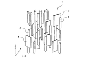
- carbon fibers 3 and scaly graphite powder 4 are oriented in a predetermined direction in the polymer matrix 2.
- the orientation direction will be described in more detail.
- the carbon fiber 3 is contained with its fiber axis direction oriented in the thickness direction of the sheet (Z direction in FIG. 2).
- the major axis direction of the scale surface is oriented in the sheet thickness direction (Z direction in FIG. 2), and the minor axis direction (normal direction of the scale surface) is a random perpendicular to the major axis.
- a random direction random direction in the XY plane of FIG. 2).
- the other heat conductive filler 5 is randomly dispersed and contained in the polymer matrix 2, unlike the carbon fiber 3 and the flaky graphite powder 4. Has been.
- the above is a schematic explanation of the heat conductive sheet 1, but when the cross section of the actual heat conductive sheet is viewed with an electron microscope, it is in a state as shown in FIG.
- the state of being oriented in the thickness direction of the sheet means a state in which the fiber axis direction of the carbon fiber exceeding 50% faces a range within 15 ° from the thickness direction of the sheet.
- the state in which the scaly graphite powder is oriented in the thickness direction of the sheet means that the surface direction of the scaly surface of the scaly graphite powder exceeding 50% is in a range of 15 ° or less from the thickness direction of the sheet. It means state.
- the state in which the normal direction of the scale surface of the flaky graphite powder is random in the plane direction means that the normal direction of the flaky graphite powder faces a range within 15 ° from a specific direction in the sheet surface. Is less than 50%.
- the normal direction of the scale-like graphite powder is random in the plane direction. It means a state that is not. Such a state of orientation can be confirmed by observing a cross section with an electron microscope.
- the material contained in such a heat conductive sheet is demonstrated.
- the polymer matrix is a member that holds the thermally conductive filler, and is made of a flexible rubber-like elastic body.
- it is required to have fluidity during the step of orienting.
- it is a thermoplastic resin
- carbon fiber and scale-like graphite powder can be oriented in the state which heated and plasticized.
- it is a reactive liquid resin
- a carbon fiber or scaly graphite powder is oriented before curing and cured while maintaining the state, a cured product in which the carbon fiber or scaly graphite powder is oriented is obtained.
- the former is relatively high in viscosity, and if the resin is plasticized to a low viscosity, the resin may be thermally deteriorated. Therefore, it is preferable to use the latter resin.
- the reactive liquid resin it is preferable to use a rubber or gel that is in a liquid state before the reaction and is cured under a predetermined condition to form a crosslinked structure.
- the cross-linked structure refers to a structure in which at least a part of the polymer is cross-linked three-dimensionally to form a cured body that does not melt by heating.
- a heat conductive filler is added to a liquid resin and to orient carbon fibers and scaly graphite powder in a fluid liquid resin, it is preferable that the viscosity is low, and after orientation Is preferably provided with the property of being curable under predetermined conditions.
- thermosetting and photo-curing methods examples include thermosetting and photo-curing methods. However, since they contain a large amount of light-shielding carbon fiber and scaly graphite powder, thermosetting rubber and gel are included. Is preferably used. More specifically, examples include addition-reactive silicones, urethane rubbers that utilize the reaction between polyols and isocyanates, acrylic rubbers that utilize radical or cation reactions of acrylates, and epoxy resins having a flexible skeleton. It is preferable to use addition reaction type silicone. This is because the addition-reactive silicone is easily filled with carbon fiber, scaly graphite powder, and other heat conductive fillers, and can be adjusted to be cured at a predetermined temperature with a catalyst or the like.
- a combination of an alkenyl group-containing polyorganosiloxane and a hydrogenorganopolysiloxane is preferable because it has a low viscosity and can be highly filled with a thermally conductive filler.
- Carbon fibers contained in the polymer matrix include carbon fibers having various shapes such as a fiber shape, a rod shape, and a needle shape. Carbon fiber has a crystal plane of graphite continuous in the fiber axis direction, and has a very high thermal conductivity in the fiber axis direction. Therefore, by aligning the fiber axis direction in a predetermined direction, the thermal conductivity in that direction can be increased.
- the carbon fiber is preferably graphitized, and examples of the raw material include condensed polycyclic hydrocarbon compounds such as naphthalene, condensed heterocyclic compounds such as PAN (polyacrylonitrile), pitch, and polybenzazole fibers.
- condensed polycyclic hydrocarbon compounds such as naphthalene
- condensed heterocyclic compounds such as PAN (polyacrylonitrile)
- pitch and polybenzazole fibers.
- mesophase pitch or polybenzazole fiber By using the mesophase pitch, the anisotropy allows the pitch to be oriented in the fiber axis direction in the spinning process, and a graphitized carbon fiber having excellent thermal conductivity in the fiber axis direction can be obtained.
- This mesophase pitch is not particularly limited as long as it can be spun.
- mesophase pitch may be used alone, that is, mesophase pitch.
- a graphitized carbon fiber having a content of 100% is particularly preferred from the viewpoints of high thermal conductivity, spinnability and quality stability.
- the polybenzazole fiber has a main chain aromatic ring, and when this is heat-treated and graphitized, a carbon powder having a highly developed graphite layer surface in the main chain direction can be obtained. Therefore, the obtained carbon fiber has particularly excellent thermal conductivity in the direction perpendicular to the C axis of the hexagonal graphite crystal structure, that is, in the direction parallel to the basal plane (graphite layer surface).
- a polymer material having an aromatic ring in the main chain tends to be graphitized more as the aromatic ring structure is larger, and when polybenzazole fiber is used, carbon fiber having extremely excellent thermal conductivity can be obtained. Can do.
- the carbon fiber there can be used a carbon fiber that has been subjected to spinning, infusibilization, and carbonization in order, pulverized or cut into a predetermined particle size, and then graphitized, or crushed or cut after carbonization and then graphitized.
- the polycondensation reaction and the cyclization reaction are more likely to proceed during the graphitization process on the surface newly exposed to the pulverization.
- Graphitized carbon fiber with improved properties can be obtained.
- the spun carbon fibers are graphitized and then pulverized, the graphitized carbon fibers are stiff, so that they can be easily pulverized, and carbon fibers having a relatively narrow fiber length distribution can be obtained by short-time pulverization.
- the fiber diameter of the carbon fiber is preferably 5 to 20 ⁇ m. When the fiber diameter is in the range of 5 to 20 ⁇ m, industrial production is easy, and the thermal conductivity of the sheet can be improved. On the other hand, when the fiber diameter is smaller than 5 ⁇ m or larger than 20 ⁇ m, the productivity is lowered.
- the average fiber length of the carbon fibers is preferably 10 to 600 ⁇ m, more preferably 80 to 500 ⁇ m. When the average fiber length is shorter than 10 ⁇ m, there is little contact between the carbon fibers in the polymer matrix, the heat transfer path becomes insufficient, and the thermal conductivity may be lowered. On the other hand, when the average fiber length is longer than 600 ⁇ m, the carbon fiber becomes bulky, and it becomes difficult to highly fill the polymer matrix.
- the average fiber length can be calculated from a particle size distribution obtained by observing the carbon fiber with a microscope.
- the average fiber length of the carbon fibers is preferably 40% or less of the sheet thickness, and the content of carbon fibers having a fiber length exceeding 80% of the sheet thickness is preferably 5% by mass or less. This is because when the content of the carbon fiber having a fiber length exceeding 80% of the sheet thickness exceeds 5% by mass, the carbon fiber exceeding the compression thickness increases when the sheet is compressed. Alternatively, if the average fiber length of the carbon fibers is 50% or less of the sheet thickness, the amount of carbon fibers exceeding the sheet thickness can be reduced even during compression. Considering these concerns, it is preferable that the particle size distribution of the carbon fiber is narrow. Moreover, it is preferable to mix and use a plurality of carbon fibers having different particle size distributions from the viewpoint of increasing the thermal conductivity.
- the aspect ratio of the carbon fiber is preferably more than 2.
- the aspect ratio is 2 or less, it is difficult to orient the carbon fibers in a specific direction and it is difficult to increase the thermal conductivity. More preferably, the aspect ratio is 5 or more.
- the aspect ratio is a value of “fiber length / fiber diameter” of the carbon fiber.
- the thermal conductivity in the fiber axis direction of the carbon fiber is preferably 400 W / m ⁇ K or more, more preferably 800 W / m ⁇ K or more, and particularly preferably 1000 W / m ⁇ K or more. This is to increase the thermal conductivity of the thermal conductive sheet.
- the carbon fiber content is preferably 60 to 150 parts by mass with respect to 100 parts by mass of the polymer matrix. If it is less than 60 parts by mass, it is difficult to increase the thermal conductivity, and if it exceeds 150 parts by mass, the viscosity of the mixed composition may increase and the orientation may deteriorate.
- the scaly graphite powder oriented in the polymer matrix includes a flat graphite powder called a scaly shape or a flat shape.
- the scaly graphite powder has a crystal plane of graphite spreading in the plane direction, and has isotropically extremely high thermal conductivity in the plane. Therefore, the thermal conductivity in the thickness direction of the sheet can be increased by aligning the surface direction of the scale surface with the thickness direction of the sheet.
- the normal direction to the scale surface is in a random direction. Therefore, it is configured to transmit heat isotropically without developing anisotropy in the sheet spreading direction.
- the scaly graphite powder examples include natural graphite and artificial graphite. It is preferable to use a scaly graphite powder produced by thermally decomposing a polymer film and pulverizing the obtained artificial graphite sheet. Such scaly graphite powder can increase the thermal conductivity in the sheet surface direction. It is preferable to use an aromatic polymer such as polyimide for the polymer film as a raw material for graphitization. This is because a highly heat conductive graphite film having a developed graphite structure can be obtained.
- the aspect ratio of the flaky graphite powder is preferably more than 2.
- the aspect ratio is 2 or less, it is difficult to orient the scaly graphite powder in a specific direction, and it is difficult to increase the thermal conductivity. More preferably, the aspect ratio is 5 or more.
- the aspect ratio here is a value of “the length / thickness (short axis) of the major axis of the scaly surface” of the scaly graphite powder.
- the higher the aspect ratio the higher the effect of increasing the thermal conductivity in the orientation direction per unit weight.
- the aspect ratio is more preferably in the range of 10 to 1000.
- the flaky graphite powder preferably has an average particle size in the range of 10 to 400 ⁇ m.
- the average particle size is less than 10 ⁇ m, the increase in viscosity is large and the characteristics are hardly improved. Further, when the average particle diameter exceeds 400 ⁇ m, dropping from the sheet becomes conspicuous.
- the content of the scaly graphite powder is preferably 10 to 70 parts by mass, more preferably 20 to 60 parts by mass with respect to 100 parts by mass of the polymer matrix. If the amount is less than 10 parts by mass, it is difficult to increase the thermal conductivity. If the amount exceeds 70 parts by mass, the viscosity of the mixed composition increases, the orientation deteriorates, and the thermal conductivity may not increase. In the range of 20 to 60 parts by mass, the thermal conductivity can be remarkably improved.
- the content of the heat conductive filler in which the carbon fiber and the scaly graphite powder are combined in the polymer matrix is preferably 80 to 180 parts by mass with respect to 100 parts by mass of the polymer matrix. If it is less than 80 parts by mass, the thermal conductivity may not be sufficiently increased, and if it exceeds 180 parts by mass, the thermal conductivity cannot be increased so much, and the viscosity of the mixed composition becomes too high. This is because it becomes difficult to orient the carbon fibers and the flaky graphite powder.
- the upper limit of the viscosity for orienting the carbon fibers and the flaky graphite powder in the mixed composition is about 1000 Pa ⁇ s when utilizing fluid orientation such as extrusion molding, and when oriented by a magnetic field. Is about 500 Pa ⁇ s. Therefore, considering the inclusion of the heat conductive filler within a predetermined viscosity that can be oriented, when the carbon fiber is contained alone, the heat conductivity of a relatively high filling can be obtained as desired. It is difficult to raise to the extent. In addition, when the scaly graphite powder is contained alone, although it seems that the thermal conductivity is likely to be increased, it cannot be highly filled, and it is difficult to increase the thermal conductivity to a desired level.
- the total amount of the carbon fiber and the flaky graphite powder is 100%
- the carbon fiber ratio is in the range of 46 to 92%
- the heat is higher than the case of the carbon fiber alone or the flaky graphite powder alone.
- the conductivity can be increased, and when it is in the range of 54 to 85%, the thermal conductivity can be drastically increased, and the maximum thermal conductivity has been successfully increased by about 30%.
- the thermally conductive sheet can contain a thermally conductive filler other than carbon fiber and scaly graphite powder.
- the heat conductive fillers other than the carbon fibers and the scaly graphite powder described above are referred to as “other heat conductive fillers”.
- Other heat conductive fillers preferably have the following properties.
- a heat conductive powder having an aspect ratio of 2 or less can be mentioned. Powders with an aspect ratio of 2 or less are less likely to increase the viscosity of the mixed composition even when added in a certain amount, and by using powders of different particle sizes in combination, Has the effect of lowering the viscosity. Since the scaly graphite powder is oriented in the thickness direction of the sheet and includes a heat conductive filler having a small aspect ratio, the powder of the other heat conductive filler is placed in the gap between the faces of the oriented scaly graphite powder. A heat conductive sheet having a high thermal conductivity is obtained. Spherical heat conductive powder is preferable because such an effect is particularly high.
- Preferred examples of the second embodiment include a non-magnetic material or a heat conductive powder having extremely weak magnetism.
- the carbon fiber and the flaky graphite powder are oriented in a desired direction when the mixed composition is placed in a strong magnetic field of about 1 T (tesla) or more. be able to.
- the non-magnetic material and the heat conductive powder having extremely weak magnetism have little or no interaction in the magnetic field, and can be randomly dispersed without being oriented in the heat conductive sheet.
- thermoly conductive sheet by including such a non-magnetic material or a thermally conductive powder having weak magnetism in the thermally conductive sheet, heat can be easily transmitted not only in the thickness direction of the sheet but also in the surface direction. Accordingly, the contribution of the heat conductive powder acts to connect the carbon fiber and the flaky graphite powder in the sheet surface direction, and the heat conductivity in the sheet thickness direction can be improved.
- Such other thermally conductive fillers include, for example, spherical or irregular powders such as metals, metal oxides, metal nitrides, metal carbides and metal hydroxides, and spherical graphite.
- the metal include aluminum, copper, and nickel.
- the metal oxide include aluminum oxide, magnesium oxide, zinc oxide, and quartz.
- the metal nitride include boron nitride and aluminum nitride.
- Examples of the metal carbide include silicon carbide, and examples of the metal hydroxide include aluminum hydroxide.
- thermally conductive powders aluminum oxide and aluminum are preferable because they have high thermal conductivity and spherical ones are easily available, and aluminum hydroxide is easily available and increases the flame retardancy of the thermally conductive sheet. It is preferable at the point which can do.
- the average particle size of the other thermally conductive filler is preferably 0.5 to 50 ⁇ m. If the average particle diameter exceeds 50 ⁇ m, the carbon fiber and the scale-like graphite powder may approach the size and disturb their orientation. On the other hand, a thermally conductive filler having an average particle size of less than 0.5 ⁇ m has a large specific surface area, so that its viscosity is likely to increase and it is difficult to fill it with a high degree. However, if there is no adverse effect on the fillability, a heat conductive filler of less than 0.5 ⁇ m may be included.
- the average particle diameter of the thermally conductive filler can be represented by a volume average particle diameter of a particle size distribution measured by a laser diffraction scattering method (JIS R1629).
- Other heat conductive fillers are preferably added in the range of 250 to 700 parts by mass, more preferably in the range of 350 to 600 parts by mass with respect to 100 parts by mass of the polymer matrix.
- the amount is less than 250 parts by mass, the amount intervening in the gap between the carbon fibers and the flaky graphite powder is insufficient, and the thermal conductivity may be deteriorated.
- the effect of increasing the thermal conductivity is not increased, and there is a possibility that the thermal conduction by the carbon fiber or the flaky graphite powder may be hindered.
- the heat conductivity is excellent and the viscosity of the mixed composition is also suitable.
- additives can be included as long as the function as a heat conductive sheet is not impaired.
- organic components such as a plasticizer, a dispersant, a coupling agent, and an adhesive may be included.
- the mixed composition is injected into a predetermined mold.
- a mold having the same shape as the finally obtained heat conductive sheet is used here.
- a magnetic field is applied to the mixed composition in the mold, and the carbon fibers and the scaly graphite powder are oriented in the thickness direction of the sheet.
- the reactive liquid resin in the mixed composition is cured by heating while maintaining the orientation state to obtain a heat conductive sheet in which carbon fibers and scaly graphite powder are oriented in a polymer matrix.
- the viscosity of the mixed composition is preferably 10 to 500 Pa ⁇ s. If it is less than 10 Pa ⁇ s, there is a possibility that the carbon fiber, the flaky graphite powder and other heat conductive fillers may settle, and if it exceeds 500 Pa ⁇ s, the fluidity is too low and the carbon fiber and the flaky graphite powder are oriented in the magnetic field. This is because the orientation takes too long.
- the heat conductivity can be reduced to less than 10 Pa ⁇ s by using a thermally conductive filler that is difficult to settle or by combining an additive such as an anti-settling agent.
- Examples of the magnetic field lines generating source for applying the magnetic field lines include superconducting magnets, permanent magnets, electromagnets, coils, and the like.
- Superconducting magnets are preferable in that they can generate a magnetic field having a high magnetic flux density.
- the magnetic flux density of the magnetic field generated from these lines of magnetic force is preferably 1 to 30 Tesla. When the magnetic flux density is less than 1 Tesla, it becomes difficult to orient the carbon fibers and the flaky graphite powder. On the other hand, a magnetic flux density exceeding 30 Tesla is difficult to obtain practically.
- the orientation of carbon fiber and scaly graphite powder can be performed by extrusion instead of applying a magnetic field.
- carbon fibers can be oriented in the flow direction of the mixed composition during extrusion molding by utilizing the property of flow orientation. That is, after orienting carbon fibers and scaly graphite powder by extrusion molding, the mixed composition can be cured to obtain a heat conductive sheet.
- the mold used here is for obtaining a massive molded body at the stage before the final heat conductive sheet is formed.
- a bulk molded body having a substantially rectangular parallelepiped shape is formed from the mixed composition, and this is cut or cut (hereinafter, collectively referred to as “slice”) in a subsequent process to form a desired thickness.
- the method for obtaining a polymer matrix in which carbon fibers and scaly graphite powder are oriented is the same except that the mold is different.
- the obtained massive molded body is subjected to a step of slicing along a plane perpendicular to the orientation direction of the carbon fibers.
- various means such as a cutting tool, a wire rod, and a laser can be used.
- a shearing blade, a push cutting blade, a plane or the like can be used.
- the blade angle from the plane of the plane is 45 °
- the protruding blade edge is 0.5 mm
- the canna is formed on the massive shaped body with a pressure of about 0.2 to 0.3 MPa. Can be pressed to cut.
- the surface of the obtained heat conductive sheet is a slicing surface.
- a polishing step can be performed on the slice surface as necessary.
- the end face of the carbon fiber exposed from the surface of the sheet is polished using polishing paper, cloth, or file. Thereby, the exposed end surface of the carbon fiber is flattened.
- Such an end face has the effect of improving the adhesiveness with a heat generating body and a heat radiator, and reducing the thermal resistance of the heat conductive sheet finally obtained.
- the mixed composition is applied by a slit coater or a coating method to form a thin semi-cured primary sheet, and then the primary sheet is laminated and cured.
- a method of slicing from the edge is known.
- the normal direction of the scaly surface of the scaly graphite powder is aligned, so that it is oriented in one direction in the plane in addition to the thickness direction. Therefore, the heat conductive sheet in which the scaly surface of the scaly graphite powder faces a random direction cannot be obtained.
- a skin layer having a high concentration of the polymer matrix is formed on the surface when the primary sheet is formed. For this reason, when the primary sheets are laminated, this skin layer intervenes, so that a portion having a low concentration of the heat conductive filler is formed in the polymer matrix, which may hinder heat conduction. Therefore, it is not preferable to adopt such a method.
- thermal conductive sheet In the heat conductive sheet, the long axis of carbon fiber or scaly graphite powder is oriented in the sheet thickness direction, so that the thermal conductivity in the sheet thickness direction can be increased, and the short axis of scaly graphite powder is long. Since it faces in a random direction perpendicular to the axis, the contact portion between the scaly graphite powders increases as compared with the case in which it faces in a certain direction, so that the thermal conductivity in the sheet thickness direction can be increased.
- the thermal conductivity is increased without increasing the content of the thermal conductive filler so much as to the polymer matrix, and a flexible thermal conductive sheet is obtained. be able to.
- Preparation of the mixed composition 130 parts by mass of carbon fiber (average fiber length: 100 ⁇ m) and 250 parts by mass of aluminum oxide (spherical, average particle size: 10 ⁇ m) and aluminum hydroxide as other thermally conductive fillers per 100 parts by mass of the main component of the addition reaction type silicone (Amorphous, average particle size 8 ⁇ m) 250 parts by mass were mixed to obtain a mixed composition (main agent).
- the curing agent for addition reaction type silicone as with the main agent, 130 parts by mass of carbon fiber (average fiber length: 100 ⁇ m) and 100 parts by mass of the curing agent for addition reaction type silicone, and other thermally conductive fillers.
- a mixed composition As a mixture, 250 parts by mass of aluminum oxide (spherical, average particle size 10 ⁇ m) and 250 parts by mass of aluminum hydroxide (indefinite shape, average particle size 8 ⁇ m) were mixed to obtain a mixed composition (curing agent). And the mixed composition (mixture of a main ingredient and a hardening
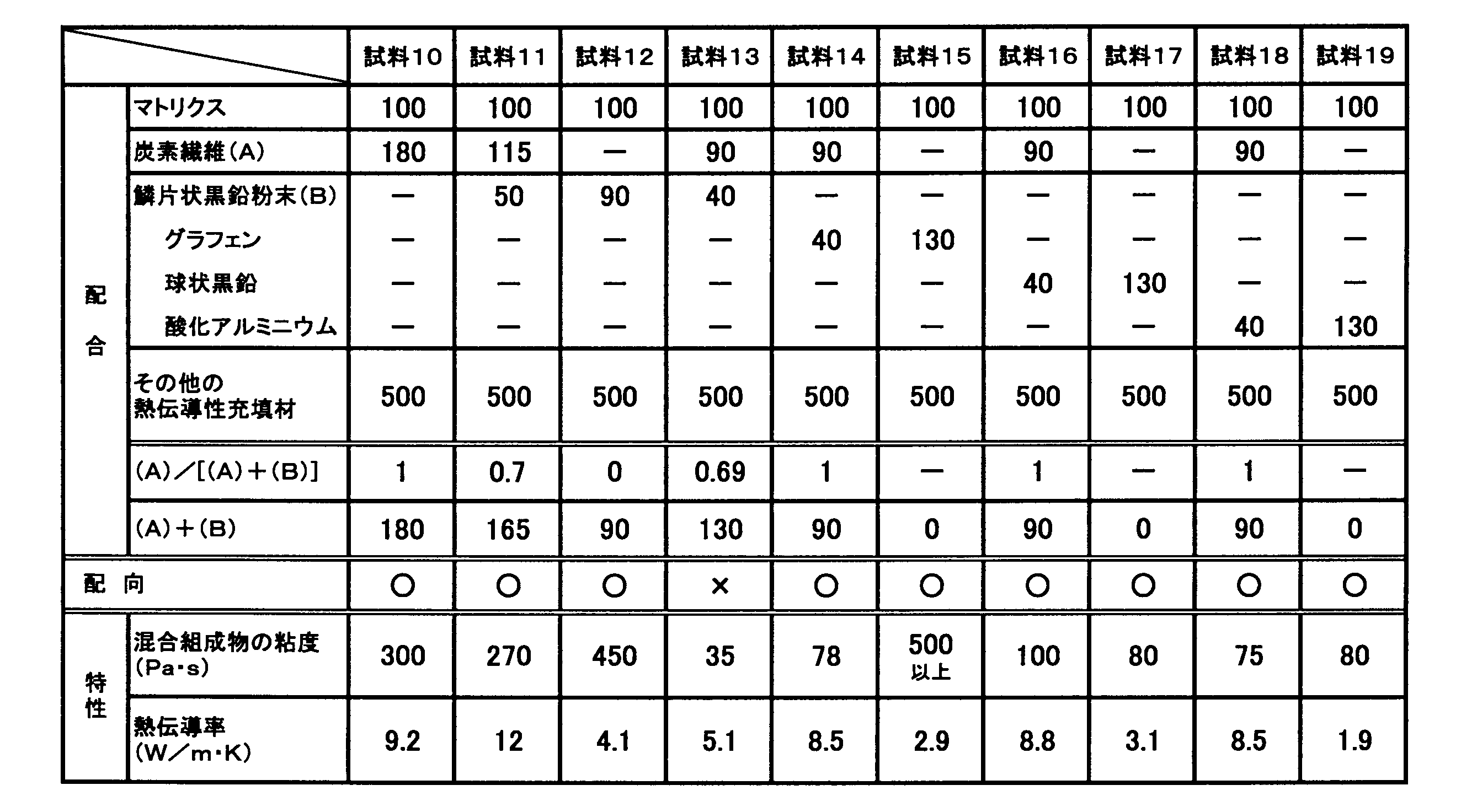
- the scaly graphite powder has an average particle size of 130 ⁇ m and an aspect ratio of about 10.
- Graphene has an average particle size of 80 ⁇ m and an aspect ratio of 8000.
- Spherical graphite has an average particle size of 20 ⁇ m.
- Aluminum oxide is spherical and has an average particle size of 20 ⁇ m.
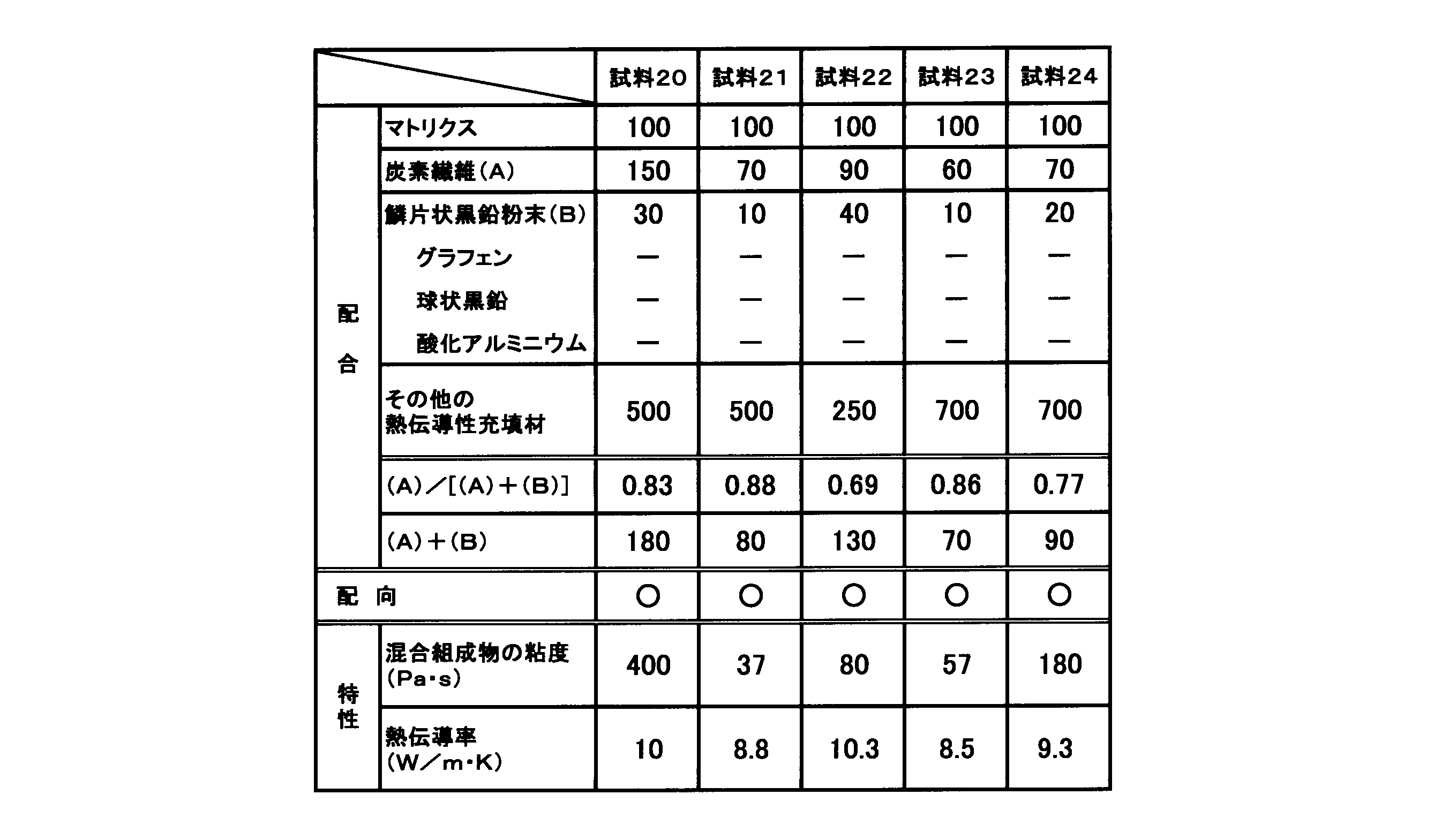
- the other thermally conductive fillers in Samples 22 to 24 are the same aluminum oxide and aluminum hydroxide as Sample 1, and the contents of both are the same.
- the average fiber length of carbon fibers was measured with an electron microscope. Specifically, the length of 100 carbon fibers was measured with an electron microscope, and the average value was defined as the average fiber length.
- the average particle size of the scaly graphite powder and the heat conductive filler is a volume average particle size of particle size distribution measured by a laser diffraction scattering method (JIS R1629).
- thermal conductive sheet Each of the mixed compositions of Sample 1 to Sample 12 and Sample 14 to Sample 24 was poured into a mold, and while applying vibration to the molding material in the mold, the carbon fiber and the flake graphite powder were aligned so as to be oriented in the vertical direction of the mold. A Tesla magnetic field was applied. Subsequently, the addition reaction type silicone was cured by heating at 90 ° C. for 60 minutes, and then the molded body was taken out from the mold. The obtained molded body is a 26 mm ⁇ 26 mm square sheet having a thickness of 2 mm with the size of the test piece capable of measuring the thermal resistance described later, that is, the orientation direction of the carbon fiber or scaly graphite powder as the thickness direction. It cut
- Sample 13 was coated with the coating composition by a coater to form a thin film-like primary sheet, and this was laminated to form a mass that was completely cured, and then sliced along the laminating direction. Thus, a secondary sheet having a thickness of 2 mm was obtained. Next, a 26 mm ⁇ 26 mm square was cut out from the secondary sheet to obtain a heat conductive sheet of Sample 13.
- Sample 1 in which the thickness direction of the sheet and the orientation direction of the carbon fiber or the flaky graphite powder are randomly oriented in the normal direction of the flaky face of the flaky graphite powder.
- “ ⁇ ” indicates that the thickness direction of the sheet is aligned with the orientation direction of the carbon fiber or the scaly graphite powder, but the normal direction of the scaly surface of the scaly graphite powder is the sheet surface.
- the case of the sample 13 facing in one direction is indicated by “x”.
- Characteristics of each sample (Measurement of viscosity of mixed composition :) The viscosity of the mixed composition of each sample was measured. This viscosity is measured with a viscometer (rotary viscometer DV-E manufactured by BROOK FIELD). It is a value measured using a rotor of 14 at a rotation speed of 10 rpm and a measurement temperature of 23 ° C. Tables 1 to 3 show the viscosity of the mixed composition of each sample.
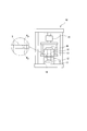
- the thermal conductivity was measured by a method based on ASTM D5470-06 using the thermal conductivity measuring device shown in the schematic diagram of FIG. More specifically, the heat conductive sheet of each sample as the test piece S is pasted on the copper block 12 whose measurement surface is 25.4 mm ⁇ 25.4 mm and whose side surface is covered with the heat insulating material 11, The load was applied by the load cell 16 so that the compression ratio was 10%.
- the lower copper block 12 is in contact with the heater 14.
- the upper copper block 13 is connected to a heat sink 15 with a fan.
- the heater 14 is heated so that the surface of the lower copper block 12 becomes 80 ° C., and the temperature ( ⁇ j0 ) of the upper copper block 13 and the heating value of the heater ( Q) was measured, the thermal resistance of each sample was calculated from the following formula (1), and the thermal conductivity was further calculated from the following formula (2). Moreover, the thickness T of each test piece S at this time was also measured.
- T Thermal conductivity
- Sample evaluation (Hardness:) About the hardness of the heat conductive sheet of each sample, it was in the range of E32 to E37 in Sample 1 to Sample 12 and Sample 14 to Sample 24, and was almost the same. However, Sample 13 was E60, which was harder than the other samples.
- Sample 1 contains 130 parts of carbon fiber (not including scaly graphite powder), and sample 9 contains 130 parts of scaly graphite powder (not containing carbon fiber), both of which contain a heat conductive filler. Although the amount was the same, the viscosity of the mixed composition was lower in sample 1 and the thermal conductivity was higher (contrast of sample 1 and sample 9).
- Sample 2 to 8 in which the total amount of carbon fiber and scaly graphite powder is 130 parts by mass, Sample 2 to Sample 7 do not contain scaly graphite powder but are more than Sample 1 that contains 130 parts by mass of carbon fiber.
- the thermal conductivity was high.
- Sample 2 to Sample 7 especially in Sample 3 to Sample 6, the thermal conductivity is 20% or more higher than that of Sample 1, and the combination of carbon fiber and scaly graphite powder enables carbon fiber alone or scaly graphite.
- the thermal conductivity could be dramatically increased as compared with the case of powder alone (Comparison between Sample 1 and Sample 2 to Sample 7).
- Sample 2 which has improved thermal conductivity as compared with Sample 1 that does not contain any flaky graphite powder, the ratio of carbon fibers to the total of carbon fibers and flaky graphite powder is 0.92. It can be seen that the thermal conductivity can be improved by mixing so as to be 0.92 or less.
- the ratio of the carbon fiber to the total of the carbon fiber and the flaky graphite powder is 0.46. It can be seen that the thermal conductivity can be improved by mixing so that the ratio is 0.46 or more.
- the thermal conductivity is higher than that of carbon fiber alone or scaly graphite powder alone.
- Sample 5 with a carbon fiber ratio of 0.62 shows that its thermal conductivity is 30% or more higher than that of Sample 1 which is carbon fiber alone (Sample 1 and Sample 2 to Sample 7). Contrast).
- Sample 4 When comparing the heat conductive sheets of Sample 4 and Sample 13 which have the same composition but differ in whether the normal direction of the scale surface of the scaly graphite powder is random or in one direction, Sample 4 is more thermally conductive than Sample 13. It was excellent in nature. From this, it can be seen that the thermal conductivity can be greatly improved by the random normal direction of the scaly surface of the scaly graphite powder (contrast of sample 4 and sample 13).
- sample 17 using the spherical graphite powder instead of the flaky graphite powder was seen, although the viscosity was lower than that of the sample 9 using the spherical graphite powder, the thermal conductivity was low.
- sample 16 having a composition in which a part of the carbon fiber is replaced with a spherical graphite powder with respect to the sample 1 of the carbon fiber alone has a lower thermal conductivity than the sample 1, and the carbon fiber and the spherical graphite powder. It can be seen that the effect of increasing the thermal conductivity is not seen even if the sample is used in combination (contrast of sample 1, sample 16, and sample 17).
- sample 19 using aluminum oxide instead of the scaly graphite powder was seen, although the viscosity was lower than that of the sample 9 using the spherical graphite powder, the thermal conductivity was low. Further, sample 18 having a composition in which a part of the carbon fiber is replaced with aluminum oxide with respect to sample 1 of carbon fiber alone has a lower thermal conductivity than sample 1, and the carbon fiber and aluminum oxide are used in combination. Even so, it can be seen that the effect of increasing the thermal conductivity as in the case of using the carbon fiber and the scaly graphite powder is not seen (contrast of the sample 1, the sample 18 and the sample 19).
- the total amount of carbon fiber and flaky graphite powder and the other amounts of the carbon fiber and flaky graphite powder are 130 parts by mass and the other thermally conductive fillers are 500 parts by mass.
- the sample 20 to Sample 24 in which the blending amount of the heat conductive filler was changed the sample 20 had a slightly higher viscosity, but the heat conductivity was higher than that of the sample 1 carbon fiber alone.
- Sample 21 has a total of 80 parts by mass of carbon fiber and scaly graphite powder, and the amount of thermally conductive filler is reduced to about 60% compared to 130 parts by mass of sample 1 alone. Regardless, there was not much decrease in thermal conductivity.
- Sample 22 has the same blending amount of carbon fiber + flaky graphite powder as Samples 2 to 8, but the amount of other heat conductive fillers is reduced by half, but there is almost no decrease in thermal conductivity. It was almost the same level. And since the total of carbon fiber + scaly graphite powder was as little as 70 parts by mass in sample 23, the thermal conductivity could not be increased even if other heat conductive fillers were added in an amount as much as 700 parts by mass. However, in sample 24, a high thermal conductivity was obtained.
- the polymer Since the total amount of carbon fiber, scaly graphite powder, and other thermally conductive fillers is 380 parts by mass in Sample 22, and 790 parts by mass in Sample 24, the polymer is high.
- the total amount of thermally conductive filler to be added to 100 parts by mass of the matrix, that is, the total of carbon fiber, flaky graphite powder and other thermally conductive fillers is 380 to 790 parts by mass. It turns out that a viscosity is suitable and the heat conductivity of the heat conductive sheet obtained becomes high.
Abstract
Description
以上のような背景のもとになされたのが本発明である。即ち本発明は、熱伝導性の高い熱伝導性シートを提供することを目的とする。
高分子マトリクス中に分散した炭素繊維と鱗片状黒鉛粉末とを含む熱伝導性シートであって、前記鱗片状黒鉛粉末が、前記炭素繊維どうしの間に介在し、前記炭素繊維の繊維軸方向がシートの厚み方向に配向し、前記鱗片状黒鉛粉末の鱗片面の長軸方向がシートの厚み方向に配向するとともに、該鱗片面に対する法線方向がシートの面方向にランダムに向いており、前記炭素繊維と鱗片状黒鉛粉末との質量割合が120:10~60:70の範囲内にある熱伝導性シートである。
高分子マトリクス100質量部に対して、炭素繊維と鱗片状黒鉛粉末の合計質量が80~180質量部となる割合で炭素繊維と鱗片状黒鉛粉末とを含むため、熱伝導性シートの柔軟性を損なうこともなく、柔軟な熱伝伝導性シートを得ることができる。
炭素繊維および鱗片状黒鉛粉末以外の熱伝導性充填材をさらに含み、この熱伝導性充填材の平均粒径が前記炭素繊維の平均繊維長および前記鱗片状黒鉛粉末の平均粒径よりも小さく、アスペクト比が2以下であるものとしたため、シート厚方向だけでなくシート厚に対する垂直方向での熱伝導性充填材どうしの接触を高め、結果的にシート厚方向の熱伝導性を高めることができる。
炭素繊維や鱗片状黒鉛粉末以外のその他の熱伝導性充填材を酸化アルミニウムや水酸化アルミニウムとしたため、磁場の影響を受けずに高分子マトリクス中にランダムに分散させることができ、炭素繊維や鱗片状黒鉛粉末の隙間に介在させて熱伝導性シートの熱伝導性を高めることができる。
高分子マトリクス100質量部に対して、前記炭素繊維と前記鱗片状黒鉛粉末と前記熱伝導性充填材の合計を380~790質量部の割合で含むため、熱伝導性シートの柔軟性を損なうことなく、熱伝導性に優れた熱伝導性シートとすることができる。
熱伝導性シートは、高分子マトリクス中に炭素繊維と鱗片状黒鉛粉末、そして、炭素繊維や鱗片状黒鉛粉末以外のその他の熱伝導性充填材を含んで構成している。
また、鱗片状黒鉛粉末の鱗片面の法線方向が面方向にランダムである状態とは、その法線方向がシート面内の特定の方向から15°以内の範囲を向いている鱗片状黒鉛粉末が50%未満である状態を意味するものとする。換言すれば、法線方向がシート面内の特定の方向から15°以内の範囲を向いている鱗片状黒鉛粉末が50%を超える場合は、鱗片状黒鉛粉末の法線方向が面方向にランダムではない状態を意味するものとする。
こうした配向の様子は、電子顕微鏡によって断面を観察することで確認することができる。
(高分子マトリクス:)
高分子マトリクスは、熱伝導性充填材を保持する部材であり、柔軟なゴム状弾性体でなる。炭素繊維や鱗片状黒鉛粉末を配向した状態で含有させるためには、配向させる工程の際に流動性を有していることが要求される。例えば、熱可塑性樹脂であれば、加熱して可塑化した状態で炭素繊維や鱗片状黒鉛粉末を配向させることができる。また、反応性液状樹脂であれば、硬化前に炭素繊維や鱗片状黒鉛粉末を配向させて、その状態を維持したまま硬化すれば、炭素繊維や鱗片状黒鉛粉末が配向した硬化物を得ることができる。前者は比較的粘度が高く、また低粘度になるまで可塑化すると樹脂が熱劣化するおそれがあるため、後者の樹脂を採用することが好ましい。
高分子マトリクスの中に含有される炭素繊維には、繊維状、棒状、針状等の各種形状の炭素繊維を含む。炭素繊維はグラファイトの結晶面が繊維軸方向に連なっており、その繊維軸方向に極めて高い熱伝導率を有する。そのため、その繊維軸方向を所定の方向に揃えることで、その方向の熱伝導率を高めることができる。
炭素繊維の平均繊維長は、好ましくは10~600μm、より好ましくは80~500μmである。平均繊維長が10μmより短いと、高分子マトリクス中において炭素繊維同士の接触が少なく、熱の伝達経路が不充分となり、熱伝導性が低下するおそれがある。一方、平均繊維長が600μmよりも長いと、炭素繊維が嵩高くなり、高分子マトリクス中に高充填することが困難になる。なお、この平均繊維長は、炭素繊維を顕微鏡で観察した粒度分布から算出することができる。
炭素繊維の含有量は、高分子マトリクス100質量部に対して60~150質量部であることが好ましい。60質量部未満では熱伝導性を高め難く、150質量部を超えると、混合組成物の粘度が高くなり配向性が悪くなるおそれがある。
高分子マトリクスの中で配向する鱗片状黒鉛粉末は、鱗片状や扁平状等と称される扁形した黒鉛粉末を含むものである。鱗片状黒鉛粉末はグラファイトの結晶面が面方向に広がっており、その面内において等方的に極めて高い熱伝導率を備える。そのため、その鱗片面の面方向をシートの厚み方向に揃えることで、シートの厚み方向の熱伝導率を高めることができる。そうした一方で、鱗片面に対する法線方向はランダムな方向を向いている。したがって、シートの広がり方向では異方性を発現せずに、等方的に熱を伝えるように構成されている。
炭素繊維は、一軸の略棒状であるため、液状樹脂内での流動抵抗が小さく配向し易いとともに、粘度が上昇し難いことから高充填し易いという特徴がある。そうした一方で、炭素繊維は一軸状であるため他の熱伝導性充填材と接触する面積は小さく、高充填しなければ熱伝導性を高め難いと思われる。
鱗片状黒鉛粉末は、鱗片状であるため、液状樹脂内での流動抵抗が大きく配向し難いとともに、粘度が上昇し易いことから高充填が難しいという特徴がある。しかし、鱗片状であるため他の熱伝導性充填材と接触する面積は大きく、比較的低充填でも熱伝導性を高め易いと思われる。
熱伝導性シートには、炭素繊維および鱗片状黒鉛粉末以外の熱伝導性充填材を含むことができる。ここでは、先に述べた炭素繊維および鱗片状黒鉛粉末以外の熱伝導性充填材を「その他の熱伝導性充填材」と称するものとする。その他の熱伝導性充填材は以下の性質を有することが好ましい。
熱伝導性シートとしての機能を損なわない範囲で種々の添加剤を含ませることができる。例えば、可塑剤、分散剤、カップリング剤、粘着剤などの有機成分を含んでも良い。またその他の成分として難燃剤、酸化防止剤、着色剤などを適宜添加してもよい。
上記原料を用いた熱伝導性シートの製造について説明する。
硬化して高分子マトリクスとなる反応性液状樹脂等の液状樹脂に、炭素繊維や鱗片状黒鉛粉末、その他の熱伝導性充填材などの熱伝導性充填材と、添加剤等を添加して混合、攪拌し、反応性液状樹脂中に熱伝導性充填材を分散させた混合組成物を得る。反応性液状樹脂が主剤と硬化剤との混合により硬化させるような液状樹脂の場合は、主剤と硬化剤の何れか一方、または両方に熱伝導性充填材を分散させることができ、主剤と硬化剤とを混合して混合組成物を得る。
このスライス面には、必要に応じて研磨工程を実行することができる。研磨工程では、研磨紙や布やヤスリなどを用いて、シートの表面から露出した炭素繊維の端面を研磨する。これにより、露出した炭素繊維の端面が平坦に潰される。こうした端面は、発熱体や放熱体との密着性を高めて、最終的に得られる熱伝導性シートの熱抵抗を低減する効果を奏する。
また、このような1次シートを積層する方法は、1次シートの形成の際に表面に高分子マトリクスの濃度が高いスキン層が形成される。そのため、1次シートどうしを積層するとこのスキン層が介在してしまうため、高分子マトリクス中に熱伝導性充填材の濃度の薄い部分が生じ熱伝導を阻害するおそれがある。そのため、こうした方法を採用することは好ましくない。
熱伝導性シートでは、炭素繊維や鱗片状黒鉛粉末の長軸がシート厚方向に配向しているのでシート厚方向の熱伝導率を高めることができ、また、鱗片状黒鉛粉末の短軸が長軸に垂直なランダムな方向を向いているので、一定方向を向いている場合に比べて鱗片状黒鉛粉末どうしの接触部分が増えることからシート厚方向の熱伝導率を高めることができる。
そして、炭素繊維と鱗片状黒鉛粉末を所定割合で含むため、高分子マトリクスに対して、それほど熱伝導性充填材の含有量を高めることなく熱伝導率を高め、柔軟な熱伝導性シートとすることができる。
付加反応型シリコーンの主剤100質量部に対し、炭素繊維(平均繊維長100μm)130質量部と、その他の熱伝導性充填材として酸化アルミニウム(球状、平均粒径10μm)250質量部および水酸化アルミニウム(不定形、平均粒径8μm)250質量部を混合して混合組成物(主剤)を得た。また、付加反応型シリコーンの硬化剤についても主剤と同じように、付加反応型シリコーンの硬化剤100質量部に対し、炭素繊維(平均繊維長100μm)130質量部と、その他の熱伝導性充填材として酸化アルミニウム(球状、平均粒径10μm)250質量部および水酸化アルミニウム(不定形、平均粒径8μm)250質量部を混合して混合組成物(硬化剤)を得た。そして、混合組成物(主剤)と混合組成物(硬化剤)を混合することで、試料1の混合組成物(主剤と硬化剤の混合物)を得た。
また、表1~表3に示す原材料と配合(質量部)に変更した以外は試料1と同様にして試料2~試料24の混合組成物を得た。
また、各表において、炭素繊維と鱗片状黒鉛粉末の合計質量を(A)+(B)で示し、炭素繊維と鱗片状黒鉛粉末の合計質量に対する炭素繊維の質量の割合を(A)/[(A)+(B)]で示している。
試料1~試料12および試料14~試料24の各混合組成物を型に流し込み、型内の成形材料に振動を与えながら、炭素繊維や鱗片状黒鉛粉末が型の上下方向に配向するように10テスラの磁場を印加した。続いて、90℃で60分間加熱して付加反応型シリコーンを硬化させた後、型から成形体を取り出した。得られた成形体は、後述する熱抵抗の測定ができる試験片の大きさ、即ち、炭素繊維や鱗片状黒鉛粉末の配向方向を厚み方向として、その厚みが2mmである26mm×26mm四方のシート形状となるように切断して試料1~試料12および試料14~試料24の熱伝導性シートを得た。

(混合組成物の粘度の測定:)
各試料の混合組成物の粘度を測定した。この粘度は粘度計(BROOK FIELD製回転粘度計DV-E)で、スピンドルNo.14の回転子を用い、回転速度10rpm、測定温度23℃で測定した値である。各試料の混合組成物の粘度を表1~表3に示す。
各試料の熱伝導性シートの硬さを測定した。この硬さは、JIS K6253規定に従ってタイプEデュロメータを用いて測定したE硬度の値である。
熱伝導率は、図5の概略図で示した熱伝導率測定機を用い、ASTM D5470-06に準拠した方法で測定した。より具体的には、試験片Sとしての各試料の熱伝導性シートを、測定面が25.4mm×25.4mmで側面が断熱材11で覆われた銅製ブロック12の上に貼付し、上方の銅製ブロック13で挟み、圧縮率が10%になるようにロードセル16によって荷重をかけた。ここで、下方の銅製ブロック12はヒーター14と接している。また、上方の銅製ブロック13はファン付きのヒートシンク15に接続している。次いで、下方の銅製ブロック12の表面が80℃になるようにヒーター14を発熱させ、温度が略定常状態となる15分後に、上方の銅製ブロック13の温度(θj0)とヒーターの発熱量(Q)を測定し、以下の式(1)から各試料の熱抵抗を、さらに以下の式(2)から熱伝導率を求めた。また、このときの各試験片Sの厚みTも測定した。
式(1)において、θj1は下方の銅製ブロック12の温度(80℃)、θj0は上方の銅製ブロック13の温度、Qは発熱量である。
式(2)において、Tは各試験片の厚みである。
(硬 さ:)
各試料の熱伝導性シートの硬さについては、試料1~試料12、試料14~試料24においてE32~E37の範囲内にありほぼ同じであった。しかし、試料13はE60となり他の試料よりは硬い結果となった。
試料1は炭素繊維を130部(鱗片状黒鉛粉末を含まない)、試料9は鱗片状黒鉛粉末を130部(炭素繊維を含まない)含んでおり、この両試料は熱伝導性充填材の配合量としては同量であるが、試料1の方が混合組成物の粘度は低く、熱伝導率は高い結果となった(試料1と試料9の対比)。
なお、本実施例の説明では、その他の熱伝導性充填材を含むものであっても鱗片状黒鉛粉末を含まずに炭素繊維を含む試料を炭素繊維単独、炭素繊維を含まずに鱗片状黒鉛粉末を含む試料を鱗片状黒鉛粉末単独のように称している。
2 高分子マトリクス
3 炭素繊維
4 鱗片状黒鉛粉末
5 その他の熱伝導性充填材
10 熱伝導率測定機
11 断熱材
12 下方の銅製ブロック
13 上方の銅製ブロック
14 ヒーター
15 ファン付きヒートシンク
16 ロードセル
S 試験片
θj0 上方の銅製ブロック13の温度
θj1 下方の銅製ブロック12の温度
Claims (5)
- 高分子マトリクス中に分散した炭素繊維と鱗片状黒鉛粉末とを含む熱伝導性シートであって、
前記鱗片状黒鉛粉末が、前記炭素繊維どうしの間に介在し、
前記炭素繊維の繊維軸方向がシートの厚み方向に配向し、前記鱗片状黒鉛粉末の鱗片面の長軸方向がシートの厚み方向に配向するとともに、該鱗片面に対する法線方向がシートの面方向にランダムに向いており、
前記炭素繊維と鱗片状黒鉛粉末との質量割合が120:10~60:70の範囲内にある熱伝導性シート。
- 高分子マトリクス100質量部に対して、炭素繊維と鱗片状黒鉛粉末の合計質量が80~180質量部となる割合で炭素繊維と鱗片状黒鉛粉末とを含む請求項1記載の熱伝導性シート。
- 前記炭素繊維および鱗片状黒鉛粉末以外の熱伝導性充填材をさらに含み、この熱伝導性充填材の平均粒径が前記炭素繊維の平均繊維長および前記鱗片状黒鉛粉末の平均粒径よりも小さく、アスペクト比が2以下である請求項1または請求項2記載の熱伝導性シート。
- 前記熱伝導性充填材が酸化アルミニウムと水酸化アルミニウムである請求項3記載の熱伝導性シート。
- 高分子マトリクス100質量部に対して、前記炭素繊維と前記鱗片状黒鉛粉末と前記熱伝導性充填材の合計を380~790質量部の割合で含む請求項3または請求項4記載の熱伝導性シート。
Priority Applications (5)
| Application Number | Priority Date | Filing Date | Title |
|---|---|---|---|
| US16/086,202 US10964620B2 (en) | 2016-04-11 | 2017-02-27 | Thermally conductive sheet |
| CN201780016876.7A CN108781524B (zh) | 2016-04-11 | 2017-02-27 | 导热片 |
| KR1020187023861A KR102073780B1 (ko) | 2016-04-11 | 2017-02-27 | 열전도성 시트 |
| EP17782136.0A EP3419399B1 (en) | 2016-04-11 | 2017-02-27 | Heat conductive sheet |
| JP2018511918A JP6532047B2 (ja) | 2016-04-11 | 2017-02-27 | 熱伝導性シート |
Applications Claiming Priority (2)
| Application Number | Priority Date | Filing Date | Title |
|---|---|---|---|
| JP2016-079171 | 2016-04-11 | ||
| JP2016079171 | 2016-04-11 |
Publications (1)
| Publication Number | Publication Date |
|---|---|
| WO2017179318A1 true WO2017179318A1 (ja) | 2017-10-19 |
Family
ID=60041760
Family Applications (1)
| Application Number | Title | Priority Date | Filing Date |
|---|---|---|---|
| PCT/JP2017/007389 WO2017179318A1 (ja) | 2016-04-11 | 2017-02-27 | 熱伝導性シート |
Country Status (6)
| Country | Link |
|---|---|
| US (1) | US10964620B2 (ja) |
| EP (1) | EP3419399B1 (ja) |
| JP (2) | JP6532047B2 (ja) |
| KR (1) | KR102073780B1 (ja) |
| CN (1) | CN108781524B (ja) |
| WO (1) | WO2017179318A1 (ja) |
Cited By (17)
| Publication number | Priority date | Publication date | Assignee | Title |
|---|---|---|---|---|
| JP2019172541A (ja) * | 2018-03-29 | 2019-10-10 | 日本ゼオン株式会社 | 複合シート及びその製造方法 |
| JP2019186555A (ja) * | 2016-04-11 | 2019-10-24 | 積水ポリマテック株式会社 | 熱伝導性シートおよび熱伝導性シートの製造方法 |
| WO2019244890A1 (ja) * | 2018-06-22 | 2019-12-26 | 積水ポリマテック株式会社 | 熱伝導性シート |
| WO2019244889A1 (ja) * | 2018-06-22 | 2019-12-26 | 積水ポリマテック株式会社 | 熱伝導性シート |
| WO2020050334A1 (ja) * | 2018-09-07 | 2020-03-12 | 積水ポリマテック株式会社 | 熱伝導性シート |
| WO2020105601A1 (ja) * | 2018-11-20 | 2020-05-28 | 積水ポリマテック株式会社 | 熱伝導性シート及びその製造方法 |
| US20200385624A1 (en) * | 2019-06-07 | 2020-12-10 | Eaton Intelligent Power Limited | Thermally conductive polymers |
| JPWO2019150939A1 (ja) * | 2018-01-30 | 2021-01-28 | 積水ポリマテック株式会社 | 熱拡散シートおよびバッテリーシステム |
| WO2021019982A1 (ja) * | 2019-07-31 | 2021-02-04 | 阿波製紙株式会社 | 熱伝導シート及びその製造方法 |
| KR20210028120A (ko) | 2019-09-03 | 2021-03-11 | 신에쓰 가가꾸 고교 가부시끼가이샤 | 말레이미드 수지 필름 및 말레이미드 수지 필름용 조성물 |
| CN112574574A (zh) * | 2020-12-07 | 2021-03-30 | 上海阿莱德实业股份有限公司 | 一种硅胶基碳材料取向型导热界面材料及其电磁制备方法 |
| WO2021065522A1 (ja) * | 2019-09-30 | 2021-04-08 | 積水ポリマテック株式会社 | 熱伝導性シート及びその製造方法 |
| CN112715059A (zh) * | 2018-09-26 | 2021-04-27 | 积水保力马科技株式会社 | 导热片 |
| WO2021085383A1 (ja) * | 2019-11-01 | 2021-05-06 | 積水ポリマテック株式会社 | 熱伝導性シート及びその製造方法 |
| JP6989675B1 (ja) * | 2020-10-21 | 2022-01-05 | デクセリアルズ株式会社 | 熱伝導性シート及び熱伝導性シートの製造方法 |
| CN115073067A (zh) * | 2021-03-16 | 2022-09-20 | 湖南大学 | 一种高导热材料及其制备方法 |
| WO2023190587A1 (ja) * | 2022-03-29 | 2023-10-05 | 積水ポリマテック株式会社 | 熱伝導性シート及び熱伝導性シートの製造方法 |
Families Citing this family (12)
| Publication number | Priority date | Publication date | Assignee | Title |
|---|---|---|---|---|
| KR102177818B1 (ko) * | 2019-06-24 | 2020-11-12 | 대흥특수화학(주) | 탄소계 필러를 이용한 열전도성 점착필름 |
| CN111978732B (zh) * | 2020-09-04 | 2022-05-24 | 广东思泉新材料股份有限公司 | 一种三维导热网络结构的热界面材料 |
| WO2022158600A1 (ja) * | 2021-01-25 | 2022-07-28 | 積水テクノ成型株式会社 | 樹脂組成物及び樹脂成形体 |
| DE102021109621A1 (de) * | 2021-04-16 | 2022-10-20 | BRANDENBURGISCHE TECHNISCHE UNIVERSITÄT COTTBUS-SENFTENBERG, Körperschaft des öffentlichen Rechts | Strukturbauteil und Fahrzeug |
| CN115505265A (zh) * | 2021-06-23 | 2022-12-23 | 嘉兴超维新材料科技有限公司 | 一种高导热硅橡胶垫片及其制备方法和应用 |
| WO2023190726A1 (ja) * | 2022-03-30 | 2023-10-05 | デクセリアルズ株式会社 | 熱伝導性シート及び熱伝導性シートの製造方法 |
| WO2023190756A1 (ja) * | 2022-03-31 | 2023-10-05 | デクセリアルズ株式会社 | 熱伝導性シート、熱伝導性シートの製造方法及び熱伝導性シートの表面の平滑度の検査方法 |
| WO2023190751A1 (ja) * | 2022-03-31 | 2023-10-05 | デクセリアルズ株式会社 | 熱伝導性シート及び熱伝導性シートの製造方法 |
| CN114800989B (zh) * | 2022-04-21 | 2023-08-11 | 常州富烯科技股份有限公司 | 石墨烯纤维、模具、石墨烯纤维增强导热垫片、制备方法 |
| WO2024018635A1 (ja) * | 2022-07-22 | 2024-01-25 | 株式会社レゾナック | 熱伝導シート、放熱装置及び熱伝導シートの製造方法 |
| CN115304811A (zh) * | 2022-09-05 | 2022-11-08 | 安徽宇航派蒙健康科技股份有限公司 | 一种导热塑料的制备方法 |
| CN116622238B (zh) * | 2023-04-04 | 2024-03-26 | 厦门斯研新材料技术有限公司 | 一种导热复合材料及其制备方法 |
Citations (3)
| Publication number | Priority date | Publication date | Assignee | Title |
|---|---|---|---|---|
| JP2004051852A (ja) * | 2002-07-22 | 2004-02-19 | Polymatech Co Ltd | 熱伝導性高分子成形体及びその製造方法 |
| JP2006335958A (ja) * | 2005-06-03 | 2006-12-14 | Polymatech Co Ltd | 熱伝導性成形体、並びにその製造方法及び取付け方法 |
| JP2012171986A (ja) * | 2011-02-17 | 2012-09-10 | Teijin Ltd | 熱伝導性組成物 |
Family Cites Families (16)
| Publication number | Priority date | Publication date | Assignee | Title |
|---|---|---|---|---|
| WO2005019132A1 (ja) * | 2003-08-26 | 2005-03-03 | Matsushita Electric Industrial Co., Ltd. | 高熱伝導性部材及びその製造方法ならびにそれを用いた放熱システム |
| JP2005146057A (ja) | 2003-11-12 | 2005-06-09 | Polymatech Co Ltd | 高熱伝導性成形体及びその製造方法 |
| US20100073882A1 (en) | 2006-11-01 | 2010-03-25 | Tooru Yoshikawa | Thermally conductive sheet, process for producing the same, and radiator utilizing thermally conductive sheet |
| WO2010116891A1 (ja) * | 2009-04-10 | 2010-10-14 | ポリマテック株式会社 | 熱伝導性塊状接着剤及び熱伝導性接着シート並びにそれらの製造方法 |
| JP5254870B2 (ja) | 2009-04-22 | 2013-08-07 | ポリマテック株式会社 | 熱伝導性シート及びその製造方法 |
| IT1393962B1 (it) * | 2009-05-05 | 2012-05-17 | Polimeri Europa Spa | Articoli espansi con ottima resistenza allo irraggiamento solare e ottime proprieta' termoisolanti e meccaniche |
| JP2010263946A (ja) * | 2009-05-12 | 2010-11-25 | Fujifilm Corp | 内視鏡 |
| JP2013001818A (ja) * | 2011-06-17 | 2013-01-07 | Sumitomo Chemical Co Ltd | 樹脂組成物及びこれからなるインバータ用部品 |
| JP6385038B2 (ja) * | 2013-09-30 | 2018-09-05 | 住友化学株式会社 | 摺動部材用樹脂組成物 |
| WO2015050263A1 (ja) * | 2013-10-01 | 2015-04-09 | 住友化学株式会社 | 樹脂組成物及びこれからなる放熱部品 |
| CN103740110A (zh) * | 2013-12-23 | 2014-04-23 | 华为技术有限公司 | 一种定向柔性导热材料及其成型工艺和应用 |
| WO2015198990A1 (ja) * | 2014-06-27 | 2015-12-30 | Rimtec株式会社 | 反応射出成形用配合液およびその製造方法 |
| JP6295890B2 (ja) * | 2014-08-27 | 2018-03-20 | 三菱ケミカル株式会社 | 炭素繊維束 |
| CN105001450B (zh) * | 2015-07-09 | 2018-05-18 | 天津大学 | 定向高导热碳/聚合物复合材料及制备方法 |
| CN105175994B (zh) * | 2015-08-03 | 2018-05-04 | 广东生益科技股份有限公司 | 一种覆铜板用环氧树脂组合物及其应用 |
| KR102073780B1 (ko) | 2016-04-11 | 2020-02-05 | 세키수이 폴리머텍 가부시키가이샤 | 열전도성 시트 |
-
2017
- 2017-02-27 KR KR1020187023861A patent/KR102073780B1/ko active IP Right Grant
- 2017-02-27 JP JP2018511918A patent/JP6532047B2/ja active Active
- 2017-02-27 US US16/086,202 patent/US10964620B2/en active Active
- 2017-02-27 WO PCT/JP2017/007389 patent/WO2017179318A1/ja active Application Filing
- 2017-02-27 CN CN201780016876.7A patent/CN108781524B/zh active Active
- 2017-02-27 EP EP17782136.0A patent/EP3419399B1/en active Active
-
2019
- 2019-05-08 JP JP2019088161A patent/JP6671735B2/ja active Active
Patent Citations (3)
| Publication number | Priority date | Publication date | Assignee | Title |
|---|---|---|---|---|
| JP2004051852A (ja) * | 2002-07-22 | 2004-02-19 | Polymatech Co Ltd | 熱伝導性高分子成形体及びその製造方法 |
| JP2006335958A (ja) * | 2005-06-03 | 2006-12-14 | Polymatech Co Ltd | 熱伝導性成形体、並びにその製造方法及び取付け方法 |
| JP2012171986A (ja) * | 2011-02-17 | 2012-09-10 | Teijin Ltd | 熱伝導性組成物 |
Non-Patent Citations (1)
| Title |
|---|
| See also references of EP3419399A4 * |
Cited By (44)
| Publication number | Priority date | Publication date | Assignee | Title |
|---|---|---|---|---|
| JP2019186555A (ja) * | 2016-04-11 | 2019-10-24 | 積水ポリマテック株式会社 | 熱伝導性シートおよび熱伝導性シートの製造方法 |
| US10964620B2 (en) | 2016-04-11 | 2021-03-30 | Sekisui Polymatech Co., Ltd. | Thermally conductive sheet |
| JP7315132B2 (ja) | 2018-01-30 | 2023-07-26 | 積水ポリマテック株式会社 | 熱拡散シートおよびバッテリーシステム |
| JPWO2019150939A1 (ja) * | 2018-01-30 | 2021-01-28 | 積水ポリマテック株式会社 | 熱拡散シートおよびバッテリーシステム |
| JP7247469B2 (ja) | 2018-03-29 | 2023-03-29 | 日本ゼオン株式会社 | 複合シート及びその製造方法 |
| JP2019172541A (ja) * | 2018-03-29 | 2019-10-10 | 日本ゼオン株式会社 | 複合シート及びその製造方法 |
| CN112313795A (zh) * | 2018-06-22 | 2021-02-02 | 积水保力马科技株式会社 | 热传导性片 |
| TWI807053B (zh) * | 2018-06-22 | 2023-07-01 | 日商積水保力馬科技股份有限公司 | 熱傳導性片 |
| WO2019244890A1 (ja) * | 2018-06-22 | 2019-12-26 | 積水ポリマテック株式会社 | 熱伝導性シート |
| JP6650176B1 (ja) * | 2018-06-22 | 2020-02-19 | 積水ポリマテック株式会社 | 熱伝導性シート |
| KR102646809B1 (ko) | 2018-06-22 | 2024-03-13 | 세키수이 폴리머텍 가부시키가이샤 | 열전도성 시트 |
| WO2019244889A1 (ja) * | 2018-06-22 | 2019-12-26 | 積水ポリマテック株式会社 | 熱伝導性シート |
| CN112368826A (zh) * | 2018-06-22 | 2021-02-12 | 积水保力马科技株式会社 | 热传导性片 |
| KR102614679B1 (ko) | 2018-06-22 | 2023-12-19 | 세키수이 폴리머텍 가부시키가이샤 | 열전도성 시트 |
| KR20210023863A (ko) * | 2018-06-22 | 2021-03-04 | 세키수이 폴리머텍 가부시키가이샤 | 열전도성 시트 |
| KR20210023862A (ko) * | 2018-06-22 | 2021-03-04 | 세키수이 폴리머텍 가부시키가이샤 | 열전도성 시트 |
| TWI821318B (zh) * | 2018-06-22 | 2023-11-11 | 日商積水保力馬科技股份有限公司 | 熱傳導性片 |
| JP6650175B1 (ja) * | 2018-06-22 | 2020-02-19 | 積水ポリマテック株式会社 | 熱伝導性シート |
| EP3848960A4 (en) * | 2018-09-07 | 2022-06-01 | Sekisui Polymatech Co., Ltd. | THERMOCONDUCTIVE SHEET |
| JPWO2020050334A1 (ja) * | 2018-09-07 | 2021-09-24 | 積水ポリマテック株式会社 | 熱伝導性シート |
| CN112655085A (zh) * | 2018-09-07 | 2021-04-13 | 积水保力马科技株式会社 | 导热性片 |
| JP7281093B2 (ja) | 2018-09-07 | 2023-05-25 | 積水ポリマテック株式会社 | 熱伝導性シート |
| WO2020050334A1 (ja) * | 2018-09-07 | 2020-03-12 | 積水ポリマテック株式会社 | 熱伝導性シート |
| CN112715059A (zh) * | 2018-09-26 | 2021-04-27 | 积水保力马科技株式会社 | 导热片 |
| EP3860321A1 (en) * | 2018-09-26 | 2021-08-04 | Sekisui Polymatech Co., Ltd. | Heat conductive sheet |
| EP3860321A4 (en) * | 2018-09-26 | 2022-06-29 | Sekisui Polymatech Co., Ltd. | Heat conductive sheet |
| JPWO2020105601A1 (ja) * | 2018-11-20 | 2021-02-15 | 積水ポリマテック株式会社 | 熱伝導性シート及びその製造方法 |
| WO2020105601A1 (ja) * | 2018-11-20 | 2020-05-28 | 積水ポリマテック株式会社 | 熱伝導性シート及びその製造方法 |
| US20200385624A1 (en) * | 2019-06-07 | 2020-12-10 | Eaton Intelligent Power Limited | Thermally conductive polymers |
| JP7470946B2 (ja) | 2019-07-31 | 2024-04-19 | 阿波製紙株式会社 | 熱伝導シート及びその製造方法 |
| WO2021019982A1 (ja) * | 2019-07-31 | 2021-02-04 | 阿波製紙株式会社 | 熱伝導シート及びその製造方法 |
| KR20210028120A (ko) | 2019-09-03 | 2021-03-11 | 신에쓰 가가꾸 고교 가부시끼가이샤 | 말레이미드 수지 필름 및 말레이미드 수지 필름용 조성물 |
| WO2021065522A1 (ja) * | 2019-09-30 | 2021-04-08 | 積水ポリマテック株式会社 | 熱伝導性シート及びその製造方法 |
| WO2021085383A1 (ja) * | 2019-11-01 | 2021-05-06 | 積水ポリマテック株式会社 | 熱伝導性シート及びその製造方法 |
| KR102452165B1 (ko) | 2019-11-01 | 2022-10-11 | 세키수이 폴리머텍 가부시키가이샤 | 열전도성 시트 및 그 제조 방법 |
| US11618247B2 (en) | 2019-11-01 | 2023-04-04 | Sekisui Polymatech Co., Ltd. | Thermally conductive sheet and production method for same |
| KR20220054713A (ko) * | 2019-11-01 | 2022-05-03 | 세키수이 폴리머텍 가부시키가이샤 | 열전도성 시트 및 그 제조 방법 |
| JP6892725B1 (ja) * | 2019-11-01 | 2021-06-23 | 積水ポリマテック株式会社 | 熱伝導性シート及びその製造方法 |
| JP2022067780A (ja) * | 2020-10-21 | 2022-05-09 | デクセリアルズ株式会社 | 熱伝導性シート及び熱伝導性シートの製造方法 |
| WO2022085284A1 (ja) * | 2020-10-21 | 2022-04-28 | デクセリアルズ株式会社 | 熱伝導性シート及び熱伝導性シートの製造方法 |
| JP6989675B1 (ja) * | 2020-10-21 | 2022-01-05 | デクセリアルズ株式会社 | 熱伝導性シート及び熱伝導性シートの製造方法 |
| CN112574574A (zh) * | 2020-12-07 | 2021-03-30 | 上海阿莱德实业股份有限公司 | 一种硅胶基碳材料取向型导热界面材料及其电磁制备方法 |
| CN115073067A (zh) * | 2021-03-16 | 2022-09-20 | 湖南大学 | 一种高导热材料及其制备方法 |
| WO2023190587A1 (ja) * | 2022-03-29 | 2023-10-05 | 積水ポリマテック株式会社 | 熱伝導性シート及び熱伝導性シートの製造方法 |
Also Published As
| Publication number | Publication date |
|---|---|
| US20200243414A1 (en) | 2020-07-30 |
| US10964620B2 (en) | 2021-03-30 |
| EP3419399B1 (en) | 2020-08-26 |
| KR20180133842A (ko) | 2018-12-17 |
| JP6671735B2 (ja) | 2020-03-25 |
| CN108781524B (zh) | 2020-12-25 |
| CN108781524A (zh) | 2018-11-09 |
| JPWO2017179318A1 (ja) | 2019-02-14 |
| JP6532047B2 (ja) | 2019-06-19 |
| JP2019186555A (ja) | 2019-10-24 |
| EP3419399A4 (en) | 2019-10-30 |
| EP3419399A1 (en) | 2018-12-26 |
| KR102073780B1 (ko) | 2020-02-05 |
Similar Documents
| Publication | Publication Date | Title |
|---|---|---|
| JP6671735B2 (ja) | 熱伝導性シートの製造方法 | |
| US11702579B2 (en) | Thermally conductive composition, thermally conductive sheet, and method for producing thermally conductive sheet | |
| KR102614679B1 (ko) | 열전도성 시트 | |
| WO2016208458A1 (ja) | 熱伝導性シート | |
| JP2005146057A (ja) | 高熱伝導性成形体及びその製造方法 | |
| CN111699090B (zh) | 导热性片 | |
| JP7281093B2 (ja) | 熱伝導性シート | |
| KR20210063339A (ko) | 열전도성 시트 | |
| JP2020074431A (ja) | 熱伝導性シート | |
| JP7076871B1 (ja) | 熱伝導性シート | |
| WO2023190587A1 (ja) | 熱伝導性シート及び熱伝導性シートの製造方法 | |
| WO2022210419A1 (ja) | 熱伝導性シートの製造方法 |
Legal Events
| Date | Code | Title | Description |
|---|---|---|---|
| ENP | Entry into the national phase |
Ref document number: 20187023861 Country of ref document: KR Kind code of ref document: A |
|
| WWE | Wipo information: entry into national phase |
Ref document number: 2018511918 Country of ref document: JP |
|
| WWE | Wipo information: entry into national phase |
Ref document number: 2017782136 Country of ref document: EP |
|
| ENP | Entry into the national phase |
Ref document number: 2017782136 Country of ref document: EP Effective date: 20180920 |
|
| NENP | Non-entry into the national phase |
Ref country code: DE |
|
| 121 | Ep: the epo has been informed by wipo that ep was designated in this application |
Ref document number: 17782136 Country of ref document: EP Kind code of ref document: A1 |