WO2015115156A1 - 冷間圧延設備および冷間圧延方法 - Google Patents
冷間圧延設備および冷間圧延方法 Download PDFInfo
- Publication number
- WO2015115156A1 WO2015115156A1 PCT/JP2015/050533 JP2015050533W WO2015115156A1 WO 2015115156 A1 WO2015115156 A1 WO 2015115156A1 JP 2015050533 W JP2015050533 W JP 2015050533W WO 2015115156 A1 WO2015115156 A1 WO 2015115156A1
- Authority
- WO
- WIPO (PCT)
- Prior art keywords
- meandering
- steel strip
- steel
- heating
- cold rolling
- Prior art date
Links
Images

Classifications
-
- B—PERFORMING OPERATIONS; TRANSPORTING
- B21—MECHANICAL METAL-WORKING WITHOUT ESSENTIALLY REMOVING MATERIAL; PUNCHING METAL
- B21B—ROLLING OF METAL
- B21B37/00—Control devices or methods specially adapted for metal-rolling mills or the work produced thereby
- B21B37/68—Camber or steering control for strip, sheets or plates, e.g. preventing meandering
-
- B—PERFORMING OPERATIONS; TRANSPORTING
- B21—MECHANICAL METAL-WORKING WITHOUT ESSENTIALLY REMOVING MATERIAL; PUNCHING METAL
- B21B—ROLLING OF METAL
- B21B37/00—Control devices or methods specially adapted for metal-rolling mills or the work produced thereby
- B21B37/72—Rear end control; Front end control
-
- B—PERFORMING OPERATIONS; TRANSPORTING
- B21—MECHANICAL METAL-WORKING WITHOUT ESSENTIALLY REMOVING MATERIAL; PUNCHING METAL
- B21B—ROLLING OF METAL
- B21B38/00—Methods or devices for measuring, detecting or monitoring specially adapted for metal-rolling mills, e.g. position detection, inspection of the product
-
- B—PERFORMING OPERATIONS; TRANSPORTING
- B21—MECHANICAL METAL-WORKING WITHOUT ESSENTIALLY REMOVING MATERIAL; PUNCHING METAL
- B21B—ROLLING OF METAL
- B21B45/00—Devices for surface or other treatment of work, specially combined with or arranged in, or specially adapted for use in connection with, metal-rolling mills
- B21B45/004—Heating the product
-
- B—PERFORMING OPERATIONS; TRANSPORTING
- B21—MECHANICAL METAL-WORKING WITHOUT ESSENTIALLY REMOVING MATERIAL; PUNCHING METAL
- B21C—MANUFACTURE OF METAL SHEETS, WIRE, RODS, TUBES OR PROFILES, OTHERWISE THAN BY ROLLING; AUXILIARY OPERATIONS USED IN CONNECTION WITH METAL-WORKING WITHOUT ESSENTIALLY REMOVING MATERIAL
- B21C51/00—Measuring, gauging, indicating, counting, or marking devices specially adapted for use in the production or manipulation of material in accordance with subclasses B21B - B21F
-
- B—PERFORMING OPERATIONS; TRANSPORTING
- B21—MECHANICAL METAL-WORKING WITHOUT ESSENTIALLY REMOVING MATERIAL; PUNCHING METAL
- B21B—ROLLING OF METAL
- B21B2271/00—Mill stand parameters
- B21B2271/02—Roll gap, screw-down position, draft position
-
- B—PERFORMING OPERATIONS; TRANSPORTING
- B21—MECHANICAL METAL-WORKING WITHOUT ESSENTIALLY REMOVING MATERIAL; PUNCHING METAL
- B21B—ROLLING OF METAL
- B21B2273/00—Path parameters
- B21B2273/04—Lateral deviation, meandering, camber of product
-
- B—PERFORMING OPERATIONS; TRANSPORTING
- B21—MECHANICAL METAL-WORKING WITHOUT ESSENTIALLY REMOVING MATERIAL; PUNCHING METAL
- B21B—ROLLING OF METAL
- B21B2273/00—Path parameters
- B21B2273/12—End of product
- B21B2273/14—Front end or leading end
-
- B—PERFORMING OPERATIONS; TRANSPORTING
- B21—MECHANICAL METAL-WORKING WITHOUT ESSENTIALLY REMOVING MATERIAL; PUNCHING METAL
- B21B—ROLLING OF METAL
- B21B37/00—Control devices or methods specially adapted for metal-rolling mills or the work produced thereby
- B21B37/58—Roll-force control; Roll-gap control
-
- B—PERFORMING OPERATIONS; TRANSPORTING
- B21—MECHANICAL METAL-WORKING WITHOUT ESSENTIALLY REMOVING MATERIAL; PUNCHING METAL
- B21B—ROLLING OF METAL
- B21B37/00—Control devices or methods specially adapted for metal-rolling mills or the work produced thereby
- B21B37/74—Temperature control, e.g. by cooling or heating the rolls or the product
-
- B—PERFORMING OPERATIONS; TRANSPORTING
- B21—MECHANICAL METAL-WORKING WITHOUT ESSENTIALLY REMOVING MATERIAL; PUNCHING METAL
- B21B—ROLLING OF METAL
- B21B38/00—Methods or devices for measuring, detecting or monitoring specially adapted for metal-rolling mills, e.g. position detection, inspection of the product
- B21B38/02—Methods or devices for measuring, detecting or monitoring specially adapted for metal-rolling mills, e.g. position detection, inspection of the product for measuring flatness or profile of strips
-
- B—PERFORMING OPERATIONS; TRANSPORTING
- B21—MECHANICAL METAL-WORKING WITHOUT ESSENTIALLY REMOVING MATERIAL; PUNCHING METAL
- B21B—ROLLING OF METAL
- B21B38/00—Methods or devices for measuring, detecting or monitoring specially adapted for metal-rolling mills, e.g. position detection, inspection of the product
- B21B38/04—Methods or devices for measuring, detecting or monitoring specially adapted for metal-rolling mills, e.g. position detection, inspection of the product for measuring thickness, width, diameter or other transverse dimensions of the product
-
- B—PERFORMING OPERATIONS; TRANSPORTING
- B21—MECHANICAL METAL-WORKING WITHOUT ESSENTIALLY REMOVING MATERIAL; PUNCHING METAL
- B21B—ROLLING OF METAL
- B21B39/00—Arrangements for moving, supporting, or positioning work, or controlling its movement, combined with or arranged in, or specially adapted for use in connection with, metal-rolling mills
- B21B39/02—Feeding or supporting work; Braking or tensioning arrangements, e.g. threading arrangements
- B21B39/08—Braking or tensioning arrangements
- B21B39/082—Bridle devices
Definitions
- the present invention relates to a cold rolling facility and a cold rolling method for cold rolling a steel sheet.
- an ear crack may occur at an end portion in the width direction (hereinafter referred to as an edge portion) of the steel plate during cold rolling.
- hard-rolled materials such as silicon steel plates, stainless steel plates, and high-carbon steel plates containing 1% or more of silicon become brittle materials compared to general steel plates, when cold-rolling hard-rolled materials at room temperature level , Ear cracks occur remarkably.
- the degree of ear cracking is large, the steel sheet may break during cold rolling starting from the ear cracking.
- Patent Document 1 discloses that when a silicon steel sheet is cold-rolled, a silicon steel sheet whose edge is heated to a temperature of 60 ° C. (ductility-brittle transition temperature) or higher is used as a material to be rolled.
- a cold rolling method of a silicon steel sheet supplied to a rolling mill is disclosed.
- Patent Document 2 discloses a pair of induction heating devices using C-type inductors (inductors) as means for raising the temperature of an edge portion of a steel plate by induction heating.
- both edge portions in the width direction of a steel plate (hereinafter referred to as “plate width direction”) are sandwiched in a slit of a C-type inductor from above and below in a non-contact manner.
- a high-frequency current is supplied from the power supply device to give a magnetic flux in the thickness direction of the steel sheet (hereinafter referred to as the “thickness direction”) to both edge portions of the steel plate to generate induced currents at both edge portions. Both of these edge portions are heated by Joule heat generated by.
- the overlapping length of the edge portion of the steel plate and the C-type inductor sandwiching the edge portion from the top and bottom in the thickness direction (hereinafter referred to as lap) It is necessary to set the position of the carriage that supports the C-type inductor according to the plate width of the steel plate so that the length) is a preset value.
- the wrap length changes. If the wrap length is reduced, the generation of eddy currents that block the flow of magnetic flux is reduced.
- the power factor deteriorates, the reactive current increases, and the high-frequency current flowing through the coil of the C-type inductor increases to the rated value.
- a predetermined output cannot be obtained, and as a result, insufficient heating of the edge portion may occur. Or the situation (local abnormal heating) which heats a part of edge part excessively may be reached.
- the edge part will be cracked during cold rolling of the steel sheet.
- the ear cracks cause breakage of the steel sheet during cold rolling.
- an ear wave is generated at the edge portion of the steel sheet due to deformation due to thermal stress.
- the degree of the ear wave is large, there is a possibility that drawing breakage occurs in the steel sheet during cold rolling, which makes it difficult to stably cold-roll the steel sheet. From the above, it is extremely important to control the lap length to an optimum value when the temperature of the edge portion of the cold-rolled steel plate is raised to a predetermined temperature by induction heating.
- a heating coil for heating an edge portion of a steel plate to be conveyed for example, a heating coil for heating an edge portion of a steel plate to be conveyed, a coil base body mounted with the heating coil, and the coil base body as a traveling direction of the steel plate
- an induction heating device that includes a moving mechanism that moves in a right-angle direction and a guide roller that is attached to the coil base body and contacts an edge portion of a steel plate (see Patent Document 3).
- the moving mechanism is operated so that the guide roller contacts the edge of the steel plate during induction heating of the steel plate, and the relative positional relationship between the steel plate and the heating coil is always constant. I try to keep it.
- a cart that moves back and forth in the direction perpendicular to the steel plate traveling direction is arranged at the left and right positions of the line through which the left and right edge portions of the steel plate pass, and an inductor that sandwiches the edge portion of the steel plate from above and below is installed on each of these left and right carts,
- an induction heating control method in which the edge portion of a steel sheet is heated by controlling the wrap length between the edge portion of the steel sheet and the inductor by an automatic position controller of the carriage (see Patent Document 4).
- the left and right cart correction positions added and subtracted as described above are output to the automatic position controllers of the left and right carts, thereby allowing the automatic position controller to correct the positions of the left and right carts,
- the wrap length between the left and right edge portions of the steel sheet and the left and right inductors is controlled.
- the wrap length between the edge portion of the steel plate and the inductor of the induction heating device is corrected according to the position change of the edge portion due to the meandering of the steel plate.
- feedback control for correcting the wrap length in accordance with the position change of the edge portion has been conventionally performed.
- the meandering speed of the steel plate is higher than the moving speed of the carriage on which the inductor is mounted, the above-described conventional technology sufficiently follows the feedback control of the lap length to the position change of the edge portion caused by the meandering of the steel plate. Is difficult.
- the present invention has been made in view of the above circumstances, and it is possible to suppress the occurrence of steel sheet breakage as much as possible, and to realize a cold rolling facility and a cold which can realize stable cold rolling of a steel sheet
- An object is to provide a rolling method.
- the cold rolling facility heats steel plates that are sequentially conveyed by a heating device, and arranges the heated steel plates in the conveying direction of the steel plates.
- a meandering amount measuring unit that measures a meandering amount of the steel plate before heating by the heating device, and a meandering of the steel plate before heating
- a meander correcting device for correcting a shape measuring unit for measuring the shape of the steel sheet after cold rolling by the most upstream rolling mill in the tandem rolling mill, and the steel sheet after cold rolling by the most upstream rolling mill
- a shape control unit for controlling the shape, and controlling the operation of the meandering correction device based on the measured value of the meandering amount of the steel plate by the meandering amount measuring unit, controlling the meandering of the steel plate before heating, and Shape measurement
- a control unit that controls the operation of the shape control unit based on
- the meandering correction device is disposed upstream of the heating device in the conveying direction of the steel sheet, and the meandering amount measuring unit is the meandering correction. It arrange
- the heating device includes a C-type inductor that sandwiches both edge portions in the width direction of the steel plate in a non-contact manner from both sides in the thickness direction of the steel plate. And the both edge portions of the steel plate are heated by an induction heating method.
- the steel plates sequentially conveyed are heated by a heating device, and the heated steel plates are sequentially cooled by a tandem rolling mill having a plurality of rolling mills arranged in the conveying direction of the steel plates.
- a measuring step for measuring the meandering amount of the steel sheet before heating by the heating device and the shape of the steel sheet after cold rolling by the most upstream rolling mill in the tandem rolling mill;
- Meander control for controlling meandering of the steel sheet before heating based on the measured value of the meandering amount of the steel sheet, and controlling meandering due to cold rolling of the steel sheet based on the measured value of the shape of the steel sheet
- a step for measuring the meandering amount of the steel sheet before heating by the heating device and the shape of the steel sheet after cold rolling by the most upstream rolling mill in the tandem rolling mill.
- the measuring step is arranged to be upstream of the heating device in the conveying direction of the steel plate and corrects the meander of the steel plate before heating.
- the meandering amount of the steel plate before heating is measured by a meandering amount measuring unit disposed between the correction device and the heating device.
- the heating apparatus including a C-type inductor that sandwiches both edge portions in the width direction of the steel sheet from both sides in the thickness direction of the steel sheet in a non-contact manner. And a heating step of heating both edge portions in the width direction of the steel sheet whose meandering is controlled by the meandering control step by an induction heating method.
- FIG. 1 is a diagram illustrating a configuration example of a cold rolling facility according to an embodiment of the present invention.
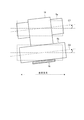
- FIG. 2 is a diagram illustrating a state in which the bridle roll of the meandering correction device according to the present embodiment is tilted.
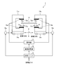
- FIG. 3 is a diagram illustrating a configuration example of a heating apparatus for cold rolling equipment in the present embodiment.
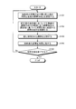
- FIG. 4 is a flowchart showing an example of the cold rolling method according to the embodiment of the present invention.
- FIG. 1 is a diagram illustrating a configuration example of a cold rolling facility according to an embodiment of the present invention.
- a cold rolling facility 1 according to the present embodiment includes a rewinder 2 at an entrance end of a conveyance path for a material to be rolled, and a tension reel 12 at an exit end.
- the cold rolling facility 1 includes a welding machine 3, a looper 4, a meandering correction device 5, a sheet width meter, along a conveying path of the material to be rolled, between the unwinding machine 2 and the tension reel 12.
- the cold rolling facility 1 includes a control unit 13 that controls the meandering correction device 5 and the shape control actuator 9.
- the unwinding machine 2 unwinds the steel plate 15 from a coil wound with a steel material such as a hot-rolled steel plate, and sequentially delivers the steel plate 15 to the material to be rolled in the cold rolling facility 1.
- the steel plate 15 paid out from the unwinding machine 2 is sequentially conveyed to the welding machine 3 located downstream of the unwinding machine 2 in the conveying direction of the steel plate 15 via a pinch roll or the like.
- the welding machine 3 is realized by using a laser welding machine or the like, and is disposed in the vicinity of the conveyance path of the material to be rolled between the unwinding machine 2 and the looper 4 as shown in FIG.
- the welding machine 3 sequentially receives a plurality of steel plates 15 paid out from the rewinding machine 2, and a tail end portion of a steel plate (hereinafter referred to as a preceding material) that precedes the conveying direction of the plurality of steel plates 15; A tip of a steel plate (hereinafter referred to as a subsequent material) following the preceding material is welded.
- the welding machine 3 sequentially performs the above-described welding process between the tail end portion of the preceding material and the tip end portion of the following material on the plurality of steel plates 15 from the rewinding machine 2, thereby the plurality of steel plates 15.
- a steel strip 16 is formed by joining the leading ends of the two. After the steel strip 16 is unloaded from the welding machine 3, the steel strip 16 is sequentially transported to the looper 4 located downstream of the welding machine 3 in the transport direction of the steel strip 16.
- the looper 4 is an apparatus for appropriately accumulating or paying out the steel strip 16 subjected to continuous processing such as cold rolling.
- the looper 4 includes a plurality of fixed rolls 4a, 4c, 4e, 4g and a direction approaching or separating from the fixed rolls 4a, 4c, 4e, 4g (hereinafter referred to as contact).
- a plurality of movable rolls 4b, 4d, and 4f that are movable in a separating direction).
- the fixed roll 4a, the movable roll 4b, the fixed roll 4c, the movable roll 4d, the fixed roll 4e, the movable roll 4f, and the fixed roll 4g are made of the steel strip 16 in this order. Arranged along the transport path.
- Each of the fixed rolls 4a, 4c, 4e, and 4g is a transport roll whose installation position is fixed, and is arranged to line up in a direction from the welding machine 3 to the meandering correction device 5, for example, as shown in FIG. .
- Each fixed roll 4a, 4c, 4e, 4g rotates around its own roll center axis by the action of a drive unit (not shown) while contacting the steel strip 16 by being wound around the steel strip 16 or the like. Thereby, each fixed roll 4a, 4c, 4e, 4g conveys the steel strip 16 along the conveyance path
- each of the movable rolls 4b, 4d, and 4f is a transport roll that can move in the contact / separation direction by the action of a moving mechanism (not shown) such as a loop car.
- the movable rolls 4b, 4d, and 4f rotate around the roll central axis while contacting the steel strip 16 by being wound around the steel strip 16 or the like.
- the movable rolls 4b, 4d, and 4f stretch the steel strip 16 between the fixed rolls 4a, 4c, 4e, and 4g, and send the steel strip 16 in the conveyance direction.
- the looper 4 having the above-described configuration is disposed upstream of the tandem rolling machine 8 in the conveying direction of the steel strip 16, specifically between the welding machine 3 and the meandering correction device 5.
- the steel strip 16 is accumulated or dispensed. Thereby, the residence time of the steel strip 16 in the looper 4 is adjusted.
- the accumulation or discharge of the steel strip 16 by the looper 4 is performed in order to absorb the transportation stop time of the steel strip 16 that occurs during the steel plate welding by the welding machine 3.
- the looper 4 receives the steel strip 16 from the welding machine 3 while the welder 3 is not welding the steel strip 16, and moves the movable rolls 4 b, 4 d, 4 f to the fixed roll 4 a. , 4c, 4e, 4g. Thereby, the looper 4 continuously conveys the steel strip 16 toward the tandem rolling mill 8 side while accumulating the steel strip 16 from the welding machine 3. On the other hand, the conveyance of the steel strip 16 from the welding machine 3 to the looper 4 is stopped while the welding machine 3 is welding the leading ends of the steel plates 15. In this case, the looper 4 brings the movable rolls 4b, 4d, and 4f closer to the fixed rolls 4a, 4c, 4e, and 4g.
- the looper 4 pays out the steel strip 16 accumulated as described above to the tandem rolling mill 8 side, and maintains the continuous conveyance of the steel strip 16 from the welding machine 3 side to the tandem rolling mill 8 side.
- the looper 4 separates the movable rolls 4b, 4d, 4f from the fixed rolls 4a, 4c, 4e, 4g again after the welding of the steel strip 16 by the welding machine 3 is completed.
- the looper 4 continuously conveys the steel strip 16 to the tandem rolling mill 8 side while accumulating the steel strip 16 received from the welding machine 3 in this state. In this manner, the looper 4 maintains continuous conveyance of the steel strip 16 from the welding machine 3 side to the tandem rolling mill 8 side.
- the steel strip 16 paid out from the looper 4 is sequentially transported to the meandering correction device 5 located downstream of the looper 4 in the transport direction of the steel strip 16.
- the meander correcting device 5 is arranged upstream of the heating device 7 in the conveying direction of the steel strip 16 and corrects the meandering of the steel strip 16 before heating by the heating device 7.
- the meandering correction device 5 includes four bridle rolls 5a to 5d and a roll tilting portion 5e that tilts the bridle rolls 5a to 5d.
- the bridle rolls 5 a to 5 d have a function as a roll body for conveying the steel strip 16 and a function as a roll body for controlling the tension of the steel strip 16.
- the bridle rolls 5a to 5d are arranged along the conveyance path of the steel strip 16 so that the winding angle of the steel strip 16 is not less than a predetermined value (for example, 90 degrees or more).
- the winding angle is the central angle of the bridle rolls 5a to 5d corresponding to the outer peripheral surface portion of the bridle rolls 5a to 5d with which the steel strip 16 contacts.
- the bridle rolls 5a to 5d arranged in this way rotate around the roll central axis by the action of a drive unit (not shown) while contacting the steel strip 16 by being wound around the steel strip 16. .
- the bridle rolls 5a to 5d convey the steel strip 16 from the looper 4 side to the heating device 7 side while applying tension to the steel strip 16 by the frictional force between the outer peripheral surface of the bridle rolls 5a to 5d.
- the bridle roll 5a stretches the steel strip 16 in cooperation with the bridle roll 5b, and conveys the steel strip 16 from the looper 4 side to the bridle roll 5b side.
- the bridle roll 5b stretches the steel strip 16 in cooperation with the bridle rolls 5a and 5c, and conveys the steel strip 16 from the bridle roll 5a side to the bridle roll 5c side.
- the bridle roll 5c stretches the steel strip 16 in cooperation with the bridle rolls 5b and 5d, and conveys the steel strip 16 from the bridle roll 5b side to the bridle roll 5d side.
- the bridle roll 5d stretches the steel strip 16 in cooperation with the bridle roll 5c, and conveys the steel strip 16 from the bridle roll 5c side to the heating device 7 side.
- the tension applied to the steel strip 16 by the bridle rolls 5a to 5d is controlled by adjusting the rotational speeds of the bridle rolls 5a to 5d.
- the bridle rolls 5a to 5d have a steering function capable of correcting the meandering of the steel strip 16.
- the bridle rolls 5a to 5d are supported by the roll tilting portion 5e so as to be rotatable about the roll center axis of the bridle rolls 5a to 5d.
- the roll tilting part 5e tilts the bridle rolls 5a to 5d so that the roll center axis of the bridle rolls 5a to 5d is tilted with respect to the horizontal direction.
- FIG. 2 is a diagram illustrating a state in which the bridle roll of the meandering correction device according to the present embodiment is tilted.
- the roll tilting part 5 e is configured so that the roll center axes C1 and C2 of the bridle rolls 5 a and 5 b that stretch the steel strip 16 are in the horizontal direction.
- the bridle rolls 5a and 5b are tilted so as to tilt.
- the roll tilting part 5e tilts also with respect to the bridle rolls 5c and 5d in the same manner as the bridle rolls 5a and 5b.
- the bridle rolls 5a to 5d are inclined by the roll tilting portion 5e, that is, by the steering function, so as to form a slope that goes down in the direction opposite to the meandering direction of the steel strip 16, and thereby the steel before heating by the heating device 7 is formed. The meandering of the belt 16 is corrected.
- the steel strip 16 carried out from the meandering correction device 5 described above passes through the plate width meter 6 disposed on the exit side of the meandering correction device 5 and is further downstream than the meandering correction device 5 in the conveying direction of the steel strip 16. It is sequentially conveyed to the arranged heating device 7.
- the board width meter 6 is a device having a function as a meandering amount measuring unit for measuring the meandering amount of the steel strip 16 before being heated by the heating device 7. As shown in FIG. 1, the meandering correction device 5 and the heating device 7 are provided. Between. The plate width meter 6 detects both edge portions of the steel strip 16 on the exit side of the meandering correction device 5 and calculates each position of the detected both edge portions. Next, the sheet width meter 6 calculates the center position in the sheet width direction of the steel strip 16 based on the calculated positions of both edge portions, and calculates the difference between this center position and the transport path center of the steel strip 16. The meandering amount of the steel strip 16 is calculated.
- the plate width meter 6 calculates the plate width of the steel strip 16 based on the obtained positions of both edge portions.
- the plate width meter 6 performs the calculation of the meandering amount and the plate width of the steel strip 16 on the exit side of the meandering correction device 5 continuously or intermittently every predetermined time.
- the plate width meter 6 transmits the calculated meandering amount of the steel strip 16 to the control unit 13 as a measured value of the meandering amount of the steel strip 16 on the exit side of the meandering correction device 5.
- the plate width meter 6 transmits the calculated plate width of the steel strip 16 to the heating device 7 as a measured value of the plate width of the steel strip 16 on the exit side of the meandering correction device 5.
- the heating device 7 heats the steel strip 16 that is sequentially conveyed before cold rolling.
- the heating device 7 is located upstream of the tandem rolling mill 8 in the conveying direction of the steel strip 16, specifically the plate width meter 6 and the most upstream of the tandem rolling mill 8. It arrange
- FIG. 3 is a diagram illustrating a configuration example of a heating apparatus for cold rolling equipment in the present embodiment. As shown in FIG.
- the heating device 7 includes a pair of C-shaped members that sandwich both edge portions 16 a and 16 b in the plate width direction of the steel strip 16 from both sides (for example, up and down) in the plate thickness direction of the steel strip 16 in a non-contact manner.
- Inductors 71a and 71b are provided.
- a heating coil 74a is provided on the legs 72a and 73a of the inductor 71a.
- the heating coil 74a applies a magnetic flux in the plate thickness direction to the edge portion 16a, thereby inductively heating the edge portion 16a.
- a leg 72b, 73b of the inductor 71b is provided with a heating coil 74b.
- the heating coil 74b applies a magnetic flux in the thickness direction to the edge portion 16b, and induction heats the edge portion 16b. To do.
- the heating device 7 includes a matching panel 77, a high frequency power supply 78, and a calculation unit 79.
- the high frequency power supply 78 is connected to the heating coils 74 a and 74 b through the matching panel 77.
- a calculation unit 79 is connected to the high frequency power supply 78.
- the calculation unit 79 sets the heating condition of the steel strip 16 based on the plate thickness of the steel strip 16, the conveyance speed, and the steel type, and outputs the high-frequency current output to the heating coils 74a and 74b according to the set heating condition. Instruct the power supply 78.
- the high frequency power supply 78 sends a high frequency current to the heating coils 74a and 74b via the matching panel 77 based on the output instruction from the calculation unit 79, whereby a magnetic flux (high frequency magnetic flux) in the plate thickness direction flows through the heating coils 74a and 74b. ). Due to this high-frequency magnetic flux, an induced current is generated in both edge portions 16a and 16b of the steel strip 16, and Joule heat is generated in both edge portions 16a and 16b due to the induced current. Both edge portions 16a and 16b are induction-heated by the generated Joule heat, and as a result, the temperature rises to a temperature equal to or higher than the ductile-brittle transition temperature.
- the heating device 7 includes carriages 75 a and 75 b that move the inductors 71 a and 71 b in the plate width direction of the steel strip 16, and position controllers 76 a and 76 b that control the positions of the inductors 71 a and 71 b. 76b.
- the inductor 71a is installed on the carriage 75a
- the inductor 71b is installed on the carriage 75b.
- the carriages 75 a and 75 b move the inductors 71 a and 71 b in the plate width direction of the steel strip 16 by moving in the plate width direction of the steel strip 16.
- a calculation unit 79 is connected to the position controllers 76a and 76b.
- the calculation unit 79 receives the measured value of the plate width of the steel strip 16 from the plate width meter 6 described above, and each of the inductors 71a and 71b in the plate width direction of the steel strip 16 according to the received measured value of the plate width.
- a target position (specifically, each target position of the heating coils 74a and 74b) is calculated.
- the calculation unit 79 transmits the calculated target positions of the inductors 71a and 71b to the position controllers 76a and 76b, respectively.
- the position controllers 76a and 76b drive and control the carriages 75a and 75b based on the target positions of the inductors 71a and 71b received from the calculation unit 79, and the position of the inductors 71a and 71b through the drive control of the carriages 75a and 75b. To control.
- the position control unit 76a controls the movement of the carriage 75a in the plate width direction of the steel strip 16 so that the position of the inductor 71a and the target position corresponding to the plate width of the steel strip 16 coincide with each other.
- the position control unit 76b controls the movement of the carriage 75b in the plate width direction of the steel strip 16 so that the position of the inductor 71b and the target position corresponding to the plate width of the steel strip 16 coincide with each other.
- the position of the inductor 71b is controlled to the target position.
- the wrap lengths La and Lb see FIG.
- edge portions 16a and 16b of the steel strip 16 and the inductors 71a and 71b are constantly controlled regardless of changes in the plate width of the steel strip 16.
- the wrap lengths La and Lb controlled in such a steady state are optimum values for raising the temperature of both edge portions 16a and 16b of the steel strip 16 to a temperature equal to or higher than the ductile-brittle transition temperature.
- the wrap length La between the edge portion 16a of the steel strip 16 and the inductor 71a is sandwiched by the leg portions 72a and 73a of the inductor 71a from above and below in the thickness direction. This is the length over which the edge portion 16a and the inductor 71a (specifically, the leg portions 72a and 73a) overlap.
- the wrap length Lb between the edge portion 16b of the steel strip 16 and the inductor 71b is determined so that the edge portion 16b and the inductor 71b (specifically, the leg portion 72b) sandwiched between the legs 72b and 73b of the inductor 71b in a non-contact manner in the plate thickness direction. , 73b).
- the tandem rolling mill 8 is a tandem type rolling mill that continuously cold-rolls steel strips 16 that are sequentially transported, and includes a plurality of rolling mills (four in this embodiment) arranged in the transport direction of the steel strip 16. Rolling mills 8a to 8d). As shown in FIG. 1, the tandem rolling mill 8 is disposed downstream of the heating device 7 in the conveying direction of the steel strip 16, specifically, between the heating device 7 and the running shear 11, and is heated by the heating device 7. The steel strip 16 after heating is sequentially cold-rolled.
- the four rolling mills 8a to 8d constituting the tandem rolling mill 8 are arranged in parallel in the conveying direction of the steel strip 16 in this order. That is, in the tandem rolling mill 8, the rolling mill 8 a is located at the most upstream side in the conveying direction of the steel strip 16, and the rolling mill 8 d is located at the most downstream side in the conveying direction of the steel strip 16.
- a rolling mill 8b is disposed downstream of the most upstream rolling mill 8a (downstream in the conveying direction of the steel strip 16).
- a rolling mill 8c is arranged between the rolling mill 8b and the most downstream rolling mill 8d.
- the steel strip 16 after being heated by the heating device 7 is conveyed from the exit side of the heating device 7 toward the entry side of the tandem rolling mill 8 (the most upstream rolling mill 8a).
- the tandem rolling mill 8 receives the heated steel strip 16 by the most upstream rolling mill 8a, and then continuously cold-rolls the received steel strip 16 by the rolling mills 8a to 8d. Thereby, the tandem rolling mill 8 sets the thickness of the steel strip 16 to a predetermined target thickness.
- the steel strip 16 after the cold rolling by the tandem rolling mill 8 is carried out to the outlet side of the most downstream rolling mill 8d, and then sequentially conveyed to the running shear 11 via a pinch roll or the like.
- the most upstream rolling mill 8a in the tandem rolling mill 8 is provided with a shape control actuator 9.
- the shape control actuator 9 has a function as a shape control unit for controlling the shape of the steel strip 16 after cold rolling by the most upstream rolling mill 8a in the tandem rolling mill 8.
- the shape control actuator 9 imparts bending or inclination to the work roll 8aa of the most upstream rolling mill 8a via a backup roll or the like, and thereby the shape of the steel strip 16 after cold rolling by the most upstream rolling mill 8a.
- the shape control actuator 9 corrects, for example, an asymmetric shape in the plate width direction of the steel strip 16 after the cold rolling to a symmetric shape.
- the shape control actuator 9 controls the shape of the steel strip 16 after the cold rolling by the most upstream rolling mill 8a, so that the steel strip 16 caused by the cold rolling of the steel strip 16 by the tandem rolling mill 8 is controlled. Correct meandering.
- the shape measuring unit 10 measures the shape of the steel strip 16 after cold rolling by the most upstream rolling mill 8a in the tandem rolling mill 8.
- the shape measuring unit 10 is configured using a roll body or the like provided with a plurality of sensors provided on the outer peripheral surface for detecting the stress of the steel strip 16 for each predetermined region in the plate width direction, and is shown in FIG. Thus, it arrange
- the shape measuring unit 10 measures the tension distribution in the sheet width direction of the steel strip 16 on the exit side of the most upstream rolling mill 8a every time it makes one rotation about its own roll center axis, and also obtains the obtained tension distribution.
- the shape of the steel strip 16 on the exit side of the most upstream rolling mill 8a (hereinafter referred to as a steel strip shape as appropriate) is measured.
- the shape measuring unit 10 transmits the measured value of the obtained steel strip shape to the control unit 13 every time the steel strip shape is measured in this way.
- the running shear 11 is disposed between the exit side of the tandem rolling mill 8 and the tension reel 12, and the steel strip 16 after cold rolling by the tandem rolling mill 8 has a predetermined length. Disconnect.
- the tension reel 12 winds the steel strip 16 cut by the running shear 11 into a coil shape.
- the control unit 13 is meandering that occurs in the steel strip 16 on the entrance side of the heating device 7 due to the shape of the steel plate 15 that is the base material of the steel strip 16 (hereinafter referred to as meandering due to the base plate shape),
- the meandering generated in the steel strip 16 on the outlet side of the heating device 7 due to the cold rolling of the steel strip 16 by the tandem rolling mill 8 (hereinafter referred to as rolling meandering as appropriate) is controlled separately.
- the control unit 13 controls the operation of the roll tilting unit 5e of the meandering correction device 5 based on the measured value of the meandering amount of the steel strip 16 by the plate width meter 6, and controls the roll tilting unit 5e.
- the control part 13 controls the meander of the steel strip 16 before the heating by the heating device 7 (meander due to the mother board shape). And the control part 13 controls operation
- the meandering of the steel strip 16 due to cold rolling (meandering due to rolling) is controlled.
- the control unit 13 controls the rotational speeds of the bridle rolls 5a to 5d of the meandering correction device 5, thereby controlling the tension of the steel strip 16 by the bridle rolls 5a to 5d.
- FIG. 4 is a flowchart showing an example of the cold rolling method according to the embodiment of the present invention.
- the cold rolling equipment 1 shown in FIG. 1 is shown in FIG. 4 for each steel strip 16 that is sequentially conveyed from the exit side of the looper 4 toward the tension reel 12.
- Each processing step of steps S101 to S105 is performed, and the steel strip 16 as the material to be rolled is heated and cold-rolled.
- the cold rolling facility 1 firstly performs cold rolling by the meandering amount of the steel strip 16 before heating by the heating device 7 and the most upstream rolling mill 8 a in the tandem rolling mill 8.
- the shape of the subsequent steel strip 16 is measured (step S101).
- the cold rolling facility 1 measures the meandering amount of the steel strip 16 before heating with the plate width meter 6 arranged between the meandering correction device 5 and the heating device 7 as shown in FIG. To do.
- the meandering correction device 5 is disposed upstream of the heating device 7 in the conveying direction of the steel strip 16, and corrects the meandering of the steel strip 16 before heating.
- the board width meter 6 measures the amount of meandering of the steel strip 16 conveyed from the exit side of the meandering correction device 5 toward the entrance side of the heating device 7, and the obtained meandering amount is measured before heating by the heating device 7.
- the amount of meandering of the steel strip 16 is transmitted to the control unit 13.
- the cold rolling equipment 1 is cold rolled by the most upstream rolling mill 8a by means of the shape measuring unit 10 arranged on the outlet side of the most upstream rolling mill 8a as shown in FIG.
- the shape of the subsequent steel strip 16 is measured.
- the shape measuring unit 10 measures the tension distribution in the plate width direction of the steel strip 16 conveyed to the outlet side of the most upstream rolling mill 8a in the tandem rolling mill 8, and based on the obtained tension distribution.
- the shape of the steel strip 16 is measured.
- the shape measuring unit 10 transmits the measured value of the steel strip shape based on such a tension distribution to the control unit 13.
- the cold rolling equipment 1 controls the meandering of the steel strip 16 before heating by the heating device 7 based on the measured value of the meandering amount of the steel strip 16 at step S101, and according to step S101. Based on the measured value of the steel strip shape, meandering due to the cold rolling of the steel strip 16 is controlled (step S102).
- step S102 the control unit 13 controls the operation of the roll tilting unit 5e of the meandering correction device 5 based on the measured value of the meandering amount of the steel strip 16 obtained from the plate width meter 6.
- the control unit 13 performs the steering function of the bridle rolls 5a to 5d of the meander correcting device 5 so as to correct the meandering of the steel strip 16 before heating, that is, meandering due to the base plate shape of the steel strip 16.
- Control controls meandering due to the base plate shape of the steel strip 16 on the entry side of the heating device 7 through the control of the steering function.
- the meandering due to the base plate shape of the steel strip 16 is feedback controlled based on the meandering amount of the steel strip 16 before heating.
- step S102 the control unit 13 controls the meandering of the steel strip 16 caused by cold rolling by the tandem rolling mill 8, that is, meandering caused by the rolling of the steel strip 16, to the meandering caused by the above-described base plate shape. Control in parallel. Specifically, the control unit 13 controls the shape control actuator 9 of the most upstream rolling mill 8 a in the tandem rolling mill 8 based on the measured value of the steel strip shape acquired from the shape measuring unit 10. At this time, the control unit 13 grasps the tension distribution in the sheet width direction of the steel strip 16 on the exit side of the most upstream rolling mill 8a based on the measured value of the steel strip shape from the shape measuring unit 10.
- the control unit 13 operates the shape control actuator 9 so that the tension distribution is linearly symmetric in the longitudinal direction of the steel strip 16 (hereinafter referred to as left-right symmetry), and preferably uniform in the plate width direction.
- the shape control actuator 9 reduces the rolling amount (hereinafter referred to as “the roll width”) of both ends of the rolling mill 8 a in the center direction of the work roll so that the tension distribution in the plate width direction of the steel strip 16 becomes symmetrical. , Called right and left reduction amount).
- the shape control actuator 9 corrects the meandering due to rolling of the steel strip 16 while correcting the steel strip shape on the exit side of the most upstream rolling mill 8a.
- the control unit 13 controls meandering due to rolling of the steel strip 16 on the exit side of the heating device 7 through the control of the shape control actuator 9. In this way, meandering due to rolling of the steel strip 16 is feedback controlled based on the shape of the steel strip 16 after cold rolling by the most upstream rolling mill 8a.
- the cold rolling equipment 1 uses the heating device 7 located on the upstream side in the conveying direction of the steel strip 16 relative to the tandem rolling mill 8, and heats the steel strip 16 whose meandering is controlled in step S102.
- the heating device 7 is provided with C-type inductors 71 a and 71 b that sandwich both edge portions 16 a and 16 b in the plate width direction of the steel strip 16 from both sides in the plate thickness direction in a non-contact manner. This is a heating type heating device.
- the heating device 7 heats both edge portions 16a and 16b of the steel strip 16 in a state in which the meandering caused by the base plate shape and the meandering caused by rolling are controlled as described above.
- the amount of meandering of the steel strip 16 when heated by the heating device 7 is reduced to a value within an allowable range in the heating device 7 by the above-described step S102.
- the permissible range of the meandering amount is that of the steel strip 16 that can steadily control the wrap lengths La and Lb between the inductors 71a and 71b of the heating device 7 shown in FIG. 3 and both edge portions 16a and 16b of the steel strip 16.
- a range of quantities for example a zero value or a value approximating zero value.
- the heating device 7 induction-heats both the edge portions 16a and 16b of the steel strip 16 in such a state that the meandering amount is reduced within the allowable range, thereby setting the temperatures of the both edge portions 16a and 16b to be ductile-brittle.
- the temperature can be raised stably to a temperature equal to or higher than the transition temperature.
- step S104 the cold rolling equipment 1 cold-rolls the steel strip 16 heated in step S103 with the tandem rolling mill 8 (step S104).
- step S104 the tandem rolling mill 8 continuously cold-rolls the heated steel strip 16 in this order using the rolling mills 8a, 8b, 8c, and 8d.
- the steel strip 16 after the cold rolling in step S104 is cut by the running shear 11 shown in FIG. 1 and then wound in a coil shape by the tension reel 12.
- step S104 the cold rolling facility 1 ends the present process if the cold rolling is completed over the entire length of the steel strip 16 that is the material to be rolled (step S105, Yes). On the other hand, if the cold rolling of the steel strip 16 is not completed (No at Step S105), the cold rolling facility 1 returns to Step S101 described above and repeats the processing steps after Step S101 as appropriate.
- the steel strip 16 is a strip-shaped steel plate formed by joining the tail end portion of the preceding material and the tip end portion of the succeeding material among the plurality of steel plates 15 that are sequentially conveyed. It is an example of the steel plate as a to-be-rolled material in a form.
- hard-rolling materials such as a silicon steel plate containing 1% or more of silicon, a stainless steel plate, a high carbon steel plate, are used, for example.
- Such a steel strip 16 to be cold-rolled generally includes a shape defect such as belly stretch or single stretch formed during hot rolling of a hot-rolled coil (hot-rolled steel plate) serving as a base material.
- a shape defect such as belly stretch or single stretch formed during hot rolling of a hot-rolled coil (hot-rolled steel plate) serving as a base material.
- the cold rolling facility 1 includes a meandering correction device 5 in the preceding stage of the heating device 7, and the meander plate of the steel strip 16 is provided by the meandering correction device 5.
- the meandering caused by the shape is always corrected.
- the meandering caused by the base plate shape of the steel strip 16 on the entry side of the heating device 7 is eliminated, so that the above-described problems such as the steel plate breakage can be solved.
- the thickness profile in the plate width direction of the hot-rolled steel plate that is the base material of the steel strip 16 has a deviation in plate thickness (the plate thickness on one end side in the plate width direction is thicker than the other end side).
- the roll position of the work roll with respect to the steel strip 16 of the tandem rolling mill 8 is parallel, the amount of reduction in the thick plate portion in the steel strip 16 becomes large, resulting in cold rolling. Meandering occurs in the steel strip 16.
- meandering due to rolling of the steel strip 16 is a series of steel strip portions continuous to the steel strip 16 during cold rolling, that is, the steel strip 16 before cold rolling located on the entry side of the tandem rolling mill 8.
- meandering due to rolling of the steel strip 16 causes meandering of the steel strip 16 heated by the heating device 7 located in the preceding stage of the tandem rolling mill 8.
- the wrap lengths La and Lb (see FIG. 3) between the inductors 71 a and 71 b of the heating device 7 and both edge portions 16 a and 16 b of the steel strip 16 change due to meandering caused by rolling of the steel strip 16.
- insufficient heating or localized abnormal heating of the edge portions 16a and 16b of the steel strip 16 occurs, which eventually leads to breakage of the steel strip 16 during cold rolling.
- the meandering correction device 5 described above corrects the meandering of the steel strip 16 by the steering function of the bridle rolls 5a to 5d.
- Such meandering of the steel strip 16 corrected by the meandering correction device 5 is meandering due to the shape of the base material, and the cause of occurrence differs from the meandering due to rolling of the steel strip 16 generated in the tandem rolling mill 8. Therefore, the meander due to the base metal shape of the steel strip 16 being conveyed toward the heating device 7 and the meander due to rolling of the steel strip 16 on the exit side of the heating device 7 are simultaneously and stably corrected by the meander correcting device 5. It is difficult.
- meandering due to rolling of the steel strip 16 is generally measured by measuring the rolling load acting on the left and right rolling cylinders when the steel strip 16 is cold-rolled, and in proportion to the difference between the measured left and right rolling loads. It is controlled by adjusting the amount of reduction.
- the deformation resistance of the steel strip 16 changes in the plate width direction. 3 may change the temperature of both edge portions 16a and 16b of the steel strip 16 due to changes in the wrap lengths La and Lb shown in FIG.
- the cold rolling equipment 1 includes a shape control actuator 9 in the most upstream rolling mill 8a in the tandem rolling mill 8, as shown in FIG. It is used to control the meandering due to rolling of the steel strip 16.
- the cold rolling equipment 1 directly measures the steel strip shape on the outlet side of the most upstream rolling mill 8a, and based on the measured value of the steel strip shape, the rolling reduction amounts on the left and right of the rolling mill 8a are measured.
- the shape control actuator 9 is controlled so as to adjust the meandering, thereby correcting the meandering due to rolling of the steel strip 16 on the exit side of the heating device 7.
- the cold rolling facility 1 shown in FIG. 1 joins the leading ends of each steel plate 15 having a silicon content of 3.0% or more with a welding machine 3 to form a steel strip 16.
- Both the edge portions 16 a and 16 b of the steel strip 16 were heated by the heating device 7, and the heated steel strip 16 was continuously cold-rolled by the tandem rolling mill 8.
- the heating conditions of the steel strip 16 by the heating apparatus 7 were set so that both the edge parts 16a and 16b of the steel strip 16 just before biting by the tandem rolling mill 8 ensure the temperature of 60 degreeC or more.
- the cold rolling facility 1 corrects the meandering caused by the base plate shape of the steel strip 16 by the steering function of the meandering correction device 5, and measures it on the outlet side of the most upstream rolling mill 8 a in the tandem rolling mill 8.
- the shape control actuator 9 was controlled based on the steel strip shape, and the meandering due to rolling of the steel strip 16 was corrected.
- the cold rolling equipment 1 heated both edge portions 16a and 16b of the steel strip 16 with the heating device 7 while maintaining the meandering correction state.
- the cold rolling facility 1 cold-rolled the steel strip 16 by changing the setting conditions of the meandering correction device 5, the heating device 7, and the shape control actuator 9.
- the cold rolling equipment 1 enables the meander correction function of the steel strip 16 by the meander correction device 5 described above, but the steel strip shape on the outlet side of the most upstream rolling mill 8a.
- the control of the shape control actuator 9 based on the measured value is invalidated, the meandering due to rolling of the steel strip 16 is not controlled, and while maintaining this state, both the edge portions 16a, 16b was heated.
- the cold rolling facility 1 has both the meandering correction function of the steel strip 16 by the meandering correction device 5 and the shape correction function (meandering correction function) of the steel strip 16 by the shape control actuator 9.
- the both edges 16a and 16b of the steel strip 16 were heated by the heating device 7 while maintaining this state invalid.
- the other conditions in Comparative Examples 1 and 2 were the same as in this example.
- the fracture occurrence rate of the steel strip 16 in this example is one of Comparative Example 2 in which the meandering correction function of the steel strip 16 by the meandering correction device 5 and the meandering correction function of the steel strip 16 by the shape control actuator 9 are invalidated. It was found to reduce to / 7.
- the amount of meandering of the steel strip on the entry side of the heating device arranged in the front stage of the tandem rolling mill that cold-rolls the steel strip that is sequentially conveyed is measured, Based on the measured value of the meandering amount, the meandering of the steel strip before heating by this heating device is controlled, and the shape of the steel strip after cold rolling by the most upstream rolling mill in this tandem rolling mill The meandering due to rolling of the steel strip is controlled based on the measured value of the obtained steel strip shape.
- the meandering amount of the steel strip on the entrance side of the heating device can be corrected to a value within the allowable range allowed for the heating device, and the influence of meandering due to rolling of the steel strip on the steel strip in the heating device can be reduced. It can be lost.
- the lap length between the heating device and the steel strip can be constantly controlled to an optimum value for cold rolling of the steel strip, so that the ductile-brittle transition at both edges of the steel strip
- the temperature can be stably raised to a temperature higher than the temperature. This realizes stable cold rolling of the steel strip by suppressing the occurrence of steel sheet breakage due to insufficient heating (ear cracks) or local abnormal heating (ear waves) at both edges of the steel strip as much as possible. can do.
- a meandering of the material to be rolled due to a sudden change in the shape of the material to be rolled or a crown change, and a meandering of the material to be rolled due to cold rolling can be suppressed together.
- the wrap length of the material to be rolled in the heating device can be constantly controlled to an optimum value, thereby Both edge portions can be stably heated to the target temperature.
- a situation in which the material to be rolled during the cold rolling breaks due to an ear crack due to insufficient heating of the edge portion and a state of the cold rolling during the cold rolling due to an ear wave due to local abnormal heating of the edge portion Since it is possible to avoid both the occurrence of drawing breakage in the material, it is possible to improve the cold rolling operation efficiency and production efficiency.
- the cold rolling equipment of the complete continuous cold tandem mill mode in which the steel sheet paid out from the coil is continuously cold rolled and wound into a coil shape is exemplified, but the present invention is It is not limited to this.
- the cold rolling equipment according to the present invention may be of a mode other than a completely continuous cold tandem mill, for example, a continuous tandem mill following the pickling line.
- tandem rolling mill in which four rolling mills are arranged in parallel in the steel strip conveying direction is provided, but the present invention is not limited to this. That is, in the present invention, the number of rolling mills installed in the cold rolling equipment (the number of stands) and the number of roll stages are not particularly limited.
- the steel strip is shown as an example of the material to be rolled, but the present invention is not limited to this.
- the cold rolling equipment and the cold rolling method according to the present invention can be applied to any of general steel plates, strip-shaped steel plates (steel strips) formed by joining a plurality of steel plates, and difficult-to-roll materials such as silicon steel plates. is there. That is, in the present invention, the steel type, joined state, and shape of the steel sheet as the material to be rolled are not particularly limited.
- the meandering correction device having four bridle rolls is illustrated, but the present invention is not limited to this.
- the meandering correction device for cold rolling equipment according to the present invention may be any device that can correct the meandering of the material to be rolled by the steering function of the roll body.
- the roll body of the meandering correction device is not limited to the bridle roll, but may be a steering roll.
- the number of roll bodies arranged in the meandering correction device is not limited to four, and may be any number.
- the shape control actuator is provided in the most upstream rolling mill among the plurality of rolling mills constituting the tandem rolling mill, but the present invention is not limited to this.
- the remaining rolling mills for example, the rolling mills 8b to 8d shown in FIG.
- a shape control actuator similar to that of the upstream rolling mill may be provided.
- the shape control actuator of each rolling mill may be controlled based on the measured value of the steel strip shape on the exit side of each rolling mill.
- the present invention is not limited to the above-described embodiments and examples, and the present invention includes a configuration in which the above-described constituent elements are appropriately combined.
- all other embodiments, examples, operation techniques, and the like made by those skilled in the art based on the above-described embodiments are included in the present invention.
- the cold rolling equipment and the cold rolling method according to the present invention are useful for cold rolling of a steel sheet, and in particular, the occurrence of steel sheet breakage is suppressed as much as possible to stably cool the steel sheet. Suitable for hot rolling.
Abstract
Description
まず、本発明の実施の形態にかかる冷間圧延設備について説明する。図1は、本発明の実施の形態にかかる冷間圧延設備の一構成例を示す図である。図1に示すように、本実施の形態にかかる冷間圧延設備1は、被圧延材の搬送経路の入口端に巻戻し機2を備え、出口端にテンションリール12を備える。また、冷間圧延設備1は、巻戻し機2とテンションリール12との間に、被圧延材の搬送経路に沿って、溶接機3と、ルーパ4と、蛇行修正装置5と、板幅計6と、加熱装置7と、タンデム圧延機8および形状測定部10と、走間シャー11とを備える。このタンデム圧延機8における最上流の圧延機8aには、形状制御アクチュエータ9が設けられている。また、冷間圧延設備1は、蛇行修正装置5および形状制御アクチュエータ9を制御する制御部13を備える。
つぎに、本発明の実施の形態にかかる冷間圧延方法について説明する。図4は、本発明の実施の形態にかかる冷間圧延方法の一例を示すフローチャートである。本実施の形態にかかる冷間圧延方法において、図1に示した冷間圧延設備1は、ルーパ4の出側からテンションリール12に向かって順次搬送される鋼帯16毎に、図4に示すステップS101~S105の各処理ステップを行い、被圧延材である鋼帯16を加熱して冷間圧延する。
つぎに、本発明の実施例について説明する。本実施例において、図1に示した冷間圧延設備1は、珪素の含有量が3.0%以上である各鋼板15の先尾端部同士を溶接機3によって接合して鋼帯16とし、この鋼帯16の両エッジ部16a,16bを加熱装置7によって加熱し、加熱後の鋼帯16をタンデム圧延機8によって連続的に冷間圧延した。この際、加熱装置7による鋼帯16の加熱条件は、タンデム圧延機8によって噛み込む直前の鋼帯16の両エッジ部16a,16bが60℃以上の温度を確保するように設定した。また、冷間圧延設備1は、蛇行修正装置5のステアリング機能によって鋼帯16の母板形状起因の蛇行を修正し、且つ、タンデム圧延機8における最上流の圧延機8aの出側において測定した鋼帯形状に基づき形状制御アクチュエータ9を制御して、鋼帯16の圧延起因の蛇行を修正した。冷間圧延設備1は、上記の蛇行修正状態を維持しつつ、加熱装置7によって鋼帯16の両エッジ部16a,16bを加熱した。

2 巻戻し機
3 溶接機
4 ルーパ
4a,4c,4e,4g 固定ロール
4b,4d,4f 可動ロール
5 蛇行修正装置
5a~5d ブライドルロール
5e ロール傾動部
6 板幅計
7 加熱装置
8 タンデム圧延機
8a~8d 圧延機
8aa ワークロール
9 形状制御アクチュエータ
10 形状測定部
11 走間シャー
12 テンションリール
13 制御部
15 鋼板
16 鋼帯
16a,16b エッジ部
71a,71b インダクタ
72a,72b,73a,73b 脚部
74a,74b 加熱コイル
75a,75b 台車
76a,76b 位置制御部
77 整合盤
78 高周波電源
79 計算ユニット
C1,C2 ロール中心軸
Claims (6)
- 順次搬送される鋼板を加熱装置によって加熱し、加熱後の前記鋼板を、前記鋼板の搬送方向に並ぶ複数の圧延機を有するタンデム圧延機によって順次冷間圧延する冷間圧延設備において、
前記加熱装置による加熱前の前記鋼板の蛇行量を測定する蛇行量測定部と、
加熱前の前記鋼板の蛇行を修正する蛇行修正装置と、
前記タンデム圧延機における最上流の圧延機による冷間圧延後の前記鋼板の形状を測定する形状測定部と、
前記最上流の圧延機による冷間圧延後の前記鋼板の形状を制御する形状制御部と、
前記蛇行量測定部による前記鋼板の蛇行量の測定値に基づき前記蛇行修正装置の動作を制御して、加熱前の前記鋼板の蛇行を制御し、且つ、前記形状測定部による前記鋼板の形状の測定値に基づき前記形状制御部の動作を制御して、前記タンデム圧延機による前記鋼板の冷間圧延に起因する前記鋼板の蛇行を制御する制御部と、
を備えたことを特徴とする冷間圧延設備。 - 前記蛇行修正装置は、前記加熱装置よりも前記鋼板の搬送方向の上流側に配置され、
前記蛇行量測定部は、前記蛇行修正装置と前記加熱装置との間に配置されることを特徴とする請求項1に記載の冷間圧延設備。 - 前記加熱装置は、前記鋼板の幅方向の両エッジ部を前記鋼板の厚さ方向の両側から非接触に挟むC型のインダクタを備え、誘導加熱方式によって前記鋼板のうちの前記両エッジ部を加熱することを特徴とする請求項1または2に記載の冷間圧延設備。
- 順次搬送される鋼板を加熱装置によって加熱し、加熱後の前記鋼板を、前記鋼板の搬送方向に並ぶ複数の圧延機を有するタンデム圧延機によって順次冷間圧延する冷間圧延方法において、
前記加熱装置による加熱前の前記鋼板の蛇行量と、前記タンデム圧延機における最上流の圧延機による冷間圧延後の前記鋼板の形状とを測定する測定ステップと、
前記鋼板の蛇行量の測定値に基づいて加熱前の前記鋼板の蛇行を制御し、且つ、前記鋼板の形状の測定値に基づいて前記鋼板の冷間圧延に起因する蛇行を制御する蛇行制御ステップと、
を含むことを特徴とする冷間圧延方法。 - 前記測定ステップは、前記加熱装置よりも前記鋼板の搬送方向の上流側に配置されて加熱前の前記鋼板の蛇行を修正する蛇行修正装置と前記加熱装置との間に配置された蛇行量測定部によって、加熱前の前記鋼板の蛇行量を測定することを特徴とする請求項4に記載の冷間圧延方法。
- 前記鋼板の幅方向の両エッジ部を前記鋼板の厚さ方向の両側から非接触に挟むC型のインダクタを備えた前記加熱装置を用い、前記蛇行制御ステップによって蛇行を制御された前記鋼板の幅方向の両エッジ部を誘導加熱方式によって加熱する加熱ステップを含むことを特徴とする請求項4または5に記載の冷間圧延方法。
Priority Applications (4)
| Application Number | Priority Date | Filing Date | Title |
|---|---|---|---|
| US15/114,540 US10259027B2 (en) | 2014-01-29 | 2015-01-09 | Cold rolling facility and cold rolling method |
| KR1020167019943A KR101780618B1 (ko) | 2014-01-29 | 2015-01-09 | 냉간 압연 설비 및 냉간 압연 방법 |
| CN201580006264.0A CN105934286B (zh) | 2014-01-29 | 2015-01-09 | 冷轧设备以及冷轧方法 |
| EP15743926.6A EP3100793B1 (en) | 2014-01-29 | 2015-01-09 | Cold-rolling facility and cold-rolling method |
Applications Claiming Priority (2)
| Application Number | Priority Date | Filing Date | Title |
|---|---|---|---|
| JP2014014646A JP6020479B2 (ja) | 2014-01-29 | 2014-01-29 | 冷間圧延設備および冷間圧延方法 |
| JP2014-014646 | 2014-01-29 |
Publications (1)
| Publication Number | Publication Date |
|---|---|
| WO2015115156A1 true WO2015115156A1 (ja) | 2015-08-06 |
Family
ID=53756733
Family Applications (1)
| Application Number | Title | Priority Date | Filing Date |
|---|---|---|---|
| PCT/JP2015/050533 WO2015115156A1 (ja) | 2014-01-29 | 2015-01-09 | 冷間圧延設備および冷間圧延方法 |
Country Status (7)
| Country | Link |
|---|---|
| US (1) | US10259027B2 (ja) |
| EP (1) | EP3100793B1 (ja) |
| JP (1) | JP6020479B2 (ja) |
| KR (1) | KR101780618B1 (ja) |
| CN (1) | CN105934286B (ja) |
| TW (1) | TWI584887B (ja) |
| WO (1) | WO2015115156A1 (ja) |
Families Citing this family (21)
| Publication number | Priority date | Publication date | Assignee | Title |
|---|---|---|---|---|
| CN107107137B (zh) * | 2015-02-02 | 2018-12-18 | 东芝三菱电机产业系统株式会社 | 轧制生产线的蛇行控制装置 |
| JP6884589B2 (ja) * | 2016-02-16 | 2021-06-09 | 株式会社神戸製鋼所 | 冷間圧延方法 |
| KR20190078337A (ko) | 2017-12-26 | 2019-07-04 | 주식회사 포스코 | 인공지능을 이용한 압연기 제어 장치 |
| CN108031716B (zh) * | 2017-12-29 | 2023-07-18 | 绿华能源(福建)有限公司 | 一种标准化移动式轻钢生产线及其自适应送料方法 |
| JP6835008B2 (ja) * | 2018-02-20 | 2021-02-24 | Jfeスチール株式会社 | 金属帯の冷間圧延方法 |
| JP6959582B2 (ja) * | 2018-11-30 | 2021-11-02 | Jfeスチール株式会社 | 非接触式搬送装置における帯状基材の蛇行制御方法 |
| WO2020213542A1 (ja) * | 2019-04-19 | 2020-10-22 | 日本製鉄株式会社 | 被圧延材の蛇行制御方法 |
| JP7269484B2 (ja) * | 2019-08-15 | 2023-05-09 | 日本製鉄株式会社 | 冷間タンデム圧延設備及び冷間タンデム圧延方法 |
| JP7311764B2 (ja) * | 2019-08-15 | 2023-07-20 | 日本製鉄株式会社 | 冷間タンデム圧延設備及び冷間タンデム圧延方法 |
| JP7192715B2 (ja) * | 2019-08-27 | 2022-12-20 | 東芝三菱電機産業システム株式会社 | 蛇行制御装置 |
| KR102180819B1 (ko) | 2019-11-01 | 2020-11-19 | 주식회사 포스코 | 인공 지능을 이용한 압연기 제어 장치 |
| KR102281202B1 (ko) | 2019-12-13 | 2021-07-26 | 주식회사 포스코 | 강판의 두께 제어 장치 |
| CN111346929A (zh) * | 2020-03-04 | 2020-06-30 | 首钢京唐钢铁联合有限责任公司 | 防止带钢断带堆钢的方法、装置、冷轧机组及存储介质 |
| JP2021179414A (ja) * | 2020-05-14 | 2021-11-18 | Jfeスチール株式会社 | 熱間圧延鋼帯の蛇行量測定装置及び熱間圧延鋼帯の蛇行量測定方法 |
| JP7331801B2 (ja) * | 2020-08-04 | 2023-08-23 | 東芝三菱電機産業システム株式会社 | 圧延機の蛇行制御装置 |
| JP6988982B1 (ja) * | 2020-10-29 | 2022-01-05 | Jfeスチール株式会社 | 金属ストリップの蛇行量検出方法及び蛇行制御方法 |
| JP7448468B2 (ja) | 2020-12-16 | 2024-03-12 | 株式会社神戸製鋼所 | 冷間圧延鋼板の製造方法 |
| US20240009723A1 (en) | 2020-12-17 | 2024-01-11 | Primetals Technologies Japan, Ltd. | Rolling mill facility |
| JP7111217B1 (ja) * | 2021-04-30 | 2022-08-02 | Jfeスチール株式会社 | 冷延鋼板の製造方法及び製造設備 |
| CN113732071B (zh) * | 2021-09-15 | 2023-09-15 | 首钢智新迁安电磁材料有限公司 | 硅钢冷连轧轧制过程温度获取方法、装置及电子设备 |
| CN114178321A (zh) * | 2021-11-17 | 2022-03-15 | 首钢智新迁安电磁材料有限公司 | 一种降低冷轧轧制力的方法 |
Citations (8)
| Publication number | Priority date | Publication date | Assignee | Title |
|---|---|---|---|---|
| JPS5370063A (en) | 1976-12-02 | 1978-06-22 | Mitsubishi Electric Corp | Beltlike rolled substance edge heat induction device |
| JPS6115919A (ja) | 1984-06-29 | 1986-01-24 | Kawasaki Steel Corp | けい素鋼板の冷間圧延方法 |
| JPH11172325A (ja) | 1997-12-09 | 1999-06-29 | Sumitomo Metal Ind Ltd | 鋼板エッジ部の誘導加熱制御方法 |
| JPH11290931A (ja) | 1998-04-16 | 1999-10-26 | Nippon Steel Corp | ストリップエッジの誘導加熱装置の加熱電力制御方法および加熱電力制御装置 |
| JP2003275811A (ja) * | 2002-03-19 | 2003-09-30 | Jfe Steel Kk | タンデム圧延機におけるストリップの蛇行制御装置及び蛇行制御方法 |
| JP2006346715A (ja) * | 2005-06-17 | 2006-12-28 | Mitsubishi-Hitachi Metals Machinery Inc | 蛇行検出装置及びその方法 |
| JP2007007754A (ja) * | 2005-06-29 | 2007-01-18 | Toshiba Mitsubishi-Electric Industrial System Corp | サイドトリマ用誘導加熱装置 |
| JP2012148310A (ja) * | 2011-01-19 | 2012-08-09 | Jfe Steel Corp | 鋼板エッジ部の加熱方法 |
Family Cites Families (18)
| Publication number | Priority date | Publication date | Assignee | Title |
|---|---|---|---|---|
| US4179913A (en) * | 1976-10-29 | 1979-12-25 | National Steel Corporation | Metal strip tensioning apparatus for use in continuous strip reduction cold mill and method |
| JPH0716683B2 (ja) * | 1986-06-27 | 1995-03-01 | 川崎製鉄株式会社 | ステンレス鋼帯用連続温間圧延設備 |
| JPH069700B2 (ja) * | 1986-07-14 | 1994-02-09 | 石川島播磨重工業株式会社 | 蛇行制御装置 |
| JPS63183713A (ja) * | 1986-09-05 | 1988-07-29 | Sumitomo Metal Ind Ltd | 蛇行制御方法 |
| JPH0284216A (ja) * | 1988-09-21 | 1990-03-26 | Kawasaki Steel Corp | 金属ストリップの溶接形状異常診断方法 |
| JP2751403B2 (ja) * | 1989-05-26 | 1998-05-18 | 住友金属工業株式会社 | ストリップの蛇行修正装置 |
| JPH0716683A (ja) * | 1993-07-02 | 1995-01-20 | Tokyo Tekko Co Ltd | 鉄筋篭の製造方法 |
| JP2002049631A (ja) * | 2000-08-01 | 2002-02-15 | Sony Corp | 情報提供装置および方法、並びに記録媒体 |
| JP2002059208A (ja) * | 2000-08-11 | 2002-02-26 | Nkk Corp | 冷延鋼帯の板幅制御方法 |
| JP4306273B2 (ja) * | 2003-02-14 | 2009-07-29 | Jfeスチール株式会社 | タンデム圧延機におけるストリップの蛇行制御装置及び蛇行制御方法 |
| JP4114646B2 (ja) * | 2004-07-07 | 2008-07-09 | 株式会社日立製作所 | 圧延制御装置,圧延制御方法及び圧延装置 |
| WO2007114181A1 (ja) * | 2006-03-31 | 2007-10-11 | Justsystems Corporation | データ入力装置、方法、及びプログラム |
| EP2197600A4 (en) * | 2007-08-28 | 2011-10-05 | Air Prod & Chem | CRYOGEN FLOW ON WORKPIECE SURFACES IN A COLD ROLLING MILL |
| JP4864173B2 (ja) | 2009-11-09 | 2012-02-01 | 三菱日立製鉄機械株式会社 | 冷間圧延材製造設備および冷間圧延方法 |
| DE102010011840B3 (de) * | 2010-03-11 | 2011-06-09 | Peter Müller GmbH | Kompressionsbandage und Verfahren zu deren Herstellung |
| JP5691231B2 (ja) * | 2010-04-16 | 2015-04-01 | Jfeスチール株式会社 | 冷間圧延方法 |
| CN103269810B (zh) * | 2010-12-24 | 2015-03-25 | 三菱日立制铁机械株式会社 | 热轧设备以及热轧方法 |
| JP7016683B2 (ja) * | 2017-12-07 | 2022-02-07 | 株式会社日立製作所 | 静止誘導電器 |
-
2014
- 2014-01-29 JP JP2014014646A patent/JP6020479B2/ja active Active
-
2015
- 2015-01-09 WO PCT/JP2015/050533 patent/WO2015115156A1/ja active Application Filing
- 2015-01-09 EP EP15743926.6A patent/EP3100793B1/en active Active
- 2015-01-09 KR KR1020167019943A patent/KR101780618B1/ko active IP Right Grant
- 2015-01-09 CN CN201580006264.0A patent/CN105934286B/zh active Active
- 2015-01-09 US US15/114,540 patent/US10259027B2/en active Active
- 2015-01-20 TW TW104101764A patent/TWI584887B/zh active
Patent Citations (8)
| Publication number | Priority date | Publication date | Assignee | Title |
|---|---|---|---|---|
| JPS5370063A (en) | 1976-12-02 | 1978-06-22 | Mitsubishi Electric Corp | Beltlike rolled substance edge heat induction device |
| JPS6115919A (ja) | 1984-06-29 | 1986-01-24 | Kawasaki Steel Corp | けい素鋼板の冷間圧延方法 |
| JPH11172325A (ja) | 1997-12-09 | 1999-06-29 | Sumitomo Metal Ind Ltd | 鋼板エッジ部の誘導加熱制御方法 |
| JPH11290931A (ja) | 1998-04-16 | 1999-10-26 | Nippon Steel Corp | ストリップエッジの誘導加熱装置の加熱電力制御方法および加熱電力制御装置 |
| JP2003275811A (ja) * | 2002-03-19 | 2003-09-30 | Jfe Steel Kk | タンデム圧延機におけるストリップの蛇行制御装置及び蛇行制御方法 |
| JP2006346715A (ja) * | 2005-06-17 | 2006-12-28 | Mitsubishi-Hitachi Metals Machinery Inc | 蛇行検出装置及びその方法 |
| JP2007007754A (ja) * | 2005-06-29 | 2007-01-18 | Toshiba Mitsubishi-Electric Industrial System Corp | サイドトリマ用誘導加熱装置 |
| JP2012148310A (ja) * | 2011-01-19 | 2012-08-09 | Jfe Steel Corp | 鋼板エッジ部の加熱方法 |
Also Published As
| Publication number | Publication date |
|---|---|
| CN105934286A (zh) | 2016-09-07 |
| TWI584887B (zh) | 2017-06-01 |
| EP3100793B1 (en) | 2018-11-21 |
| US10259027B2 (en) | 2019-04-16 |
| JP6020479B2 (ja) | 2016-11-02 |
| US20160339493A1 (en) | 2016-11-24 |
| CN105934286B (zh) | 2017-12-12 |
| JP2015139810A (ja) | 2015-08-03 |
| EP3100793A4 (en) | 2017-09-20 |
| EP3100793A1 (en) | 2016-12-07 |
| KR20160102042A (ko) | 2016-08-26 |
| KR101780618B1 (ko) | 2017-09-21 |
| TW201545822A (zh) | 2015-12-16 |
Similar Documents
| Publication | Publication Date | Title |
|---|---|---|
| JP6020479B2 (ja) | 冷間圧延設備および冷間圧延方法 | |
| JP6020475B2 (ja) | 冷間圧延設備 | |
| JP5799511B2 (ja) | 鋼板エッジ部の加熱方法 | |
| JP4814558B2 (ja) | サイドトリマ用誘導加熱装置 | |
| JP3337122B2 (ja) | 熱間圧延設備及び熱間圧延方法 | |
| JP5915595B2 (ja) | 蛇行修正装置および蛇行修正方法 | |
| WO1992002313A1 (fr) | Procede et dispositif d'assemblage de billettes | |
| JP5391762B2 (ja) | 鋼板エッジ部の誘導加熱方法 | |
| JP3187355B2 (ja) | 熱間圧延設備 | |
| JP4595388B2 (ja) | 鋼板の蛇行防止方法およびルーパ設備 | |
| JP3428400B2 (ja) | 熱間圧延設備及び熱間圧延方法 | |
| JP7126076B2 (ja) | 冷延鋼帯の製造設備および冷延鋼帯の製造方法 | |
| JP2003126902A (ja) | 熱間圧延設備及び熱間圧延方法 | |
| JPH01321010A (ja) | 熱間シートバーの加熱方法 | |
| JP3261039B2 (ja) | 連続熱間圧延における金属片の接合方法および装置 | |
| JP2005169455A (ja) | 電縫鋼管の製造装置 | |
| JP2017094379A (ja) | ループカー、ルーパー設備、及びルーパー設備を用いた鋼板の貯蔵方法 | |
| JP2000280018A (ja) | ストリップの連続プロセス処理装置 |
Legal Events
| Date | Code | Title | Description |
|---|---|---|---|
| 121 | Ep: the epo has been informed by wipo that ep was designated in this application |
Ref document number: 15743926 Country of ref document: EP Kind code of ref document: A1 |
|
| ENP | Entry into the national phase |
Ref document number: 20167019943 Country of ref document: KR Kind code of ref document: A |
|
| REEP | Request for entry into the european phase |
Ref document number: 2015743926 Country of ref document: EP |
|
| WWE | Wipo information: entry into national phase |
Ref document number: 2015743926 Country of ref document: EP |
|
| WWE | Wipo information: entry into national phase |
Ref document number: 15114540 Country of ref document: US |
|
| NENP | Non-entry into the national phase |
Ref country code: DE |