WO2014208239A1 - 硫化物固体電解質材料、硫化物ガラス、リチウム固体電池、および、硫化物固体電解質材料の製造方法 - Google Patents
硫化物固体電解質材料、硫化物ガラス、リチウム固体電池、および、硫化物固体電解質材料の製造方法 Download PDFInfo
- Publication number
- WO2014208239A1 WO2014208239A1 PCT/JP2014/063831 JP2014063831W WO2014208239A1 WO 2014208239 A1 WO2014208239 A1 WO 2014208239A1 JP 2014063831 W JP2014063831 W JP 2014063831W WO 2014208239 A1 WO2014208239 A1 WO 2014208239A1
- Authority
- WO
- WIPO (PCT)
- Prior art keywords
- solid electrolyte
- sulfide
- electrolyte material
- sulfide solid
- electrode active
- Prior art date
- Legal status (The legal status is an assumption and is not a legal conclusion. Google has not performed a legal analysis and makes no representation as to the accuracy of the status listed.)
- Ceased
Links
- 0 CC(*)CCCN Chemical compound CC(*)CCCN 0.000 description 1
Images


Classifications
-
- H—ELECTRICITY
- H01—ELECTRIC ELEMENTS
- H01M—PROCESSES OR MEANS, e.g. BATTERIES, FOR THE DIRECT CONVERSION OF CHEMICAL ENERGY INTO ELECTRICAL ENERGY
- H01M10/00—Secondary cells; Manufacture thereof
- H01M10/05—Accumulators with non-aqueous electrolyte
- H01M10/056—Accumulators with non-aqueous electrolyte characterised by the materials used as electrolytes, e.g. mixed inorganic/organic electrolytes
- H01M10/0561—Accumulators with non-aqueous electrolyte characterised by the materials used as electrolytes, e.g. mixed inorganic/organic electrolytes the electrolyte being constituted of inorganic materials only
- H01M10/0562—Solid materials
-
- C—CHEMISTRY; METALLURGY
- C03—GLASS; MINERAL OR SLAG WOOL
- C03C—CHEMICAL COMPOSITION OF GLASSES, GLAZES OR VITREOUS ENAMELS; SURFACE TREATMENT OF GLASS; SURFACE TREATMENT OF FIBRES OR FILAMENTS MADE FROM GLASS, MINERALS OR SLAGS; JOINING GLASS TO GLASS OR OTHER MATERIALS
- C03C10/00—Devitrified glass ceramics, i.e. glass ceramics having a crystalline phase dispersed in a glassy phase and constituting at least 50% by weight of the total composition
-
- C—CHEMISTRY; METALLURGY
- C03—GLASS; MINERAL OR SLAG WOOL
- C03C—CHEMICAL COMPOSITION OF GLASSES, GLAZES OR VITREOUS ENAMELS; SURFACE TREATMENT OF GLASS; SURFACE TREATMENT OF FIBRES OR FILAMENTS MADE FROM GLASS, MINERALS OR SLAGS; JOINING GLASS TO GLASS OR OTHER MATERIALS
- C03C3/00—Glass compositions
- C03C3/32—Non-oxide glass compositions, e.g. binary or ternary halides, sulfides or nitrides of germanium, selenium or tellurium
- C03C3/321—Chalcogenide glasses, e.g. containing S, Se, Te
- C03C3/323—Chalcogenide glasses, e.g. containing S, Se, Te containing halogen, e.g. chalcohalide glasses
-
- C—CHEMISTRY; METALLURGY
- C03—GLASS; MINERAL OR SLAG WOOL
- C03C—CHEMICAL COMPOSITION OF GLASSES, GLAZES OR VITREOUS ENAMELS; SURFACE TREATMENT OF GLASS; SURFACE TREATMENT OF FIBRES OR FILAMENTS MADE FROM GLASS, MINERALS OR SLAGS; JOINING GLASS TO GLASS OR OTHER MATERIALS
- C03C4/00—Compositions for glass with special properties
- C03C4/18—Compositions for glass with special properties for ion-sensitive glass
-
- H—ELECTRICITY
- H01—ELECTRIC ELEMENTS
- H01M—PROCESSES OR MEANS, e.g. BATTERIES, FOR THE DIRECT CONVERSION OF CHEMICAL ENERGY INTO ELECTRICAL ENERGY
- H01M10/00—Secondary cells; Manufacture thereof
- H01M10/05—Accumulators with non-aqueous electrolyte
- H01M10/052—Li-accumulators
-
- H—ELECTRICITY
- H01—ELECTRIC ELEMENTS
- H01M—PROCESSES OR MEANS, e.g. BATTERIES, FOR THE DIRECT CONVERSION OF CHEMICAL ENERGY INTO ELECTRICAL ENERGY
- H01M10/00—Secondary cells; Manufacture thereof
- H01M10/05—Accumulators with non-aqueous electrolyte
- H01M10/052—Li-accumulators
- H01M10/0525—Rocking-chair batteries, i.e. batteries with lithium insertion or intercalation in both electrodes; Lithium-ion batteries
-
- H—ELECTRICITY
- H01—ELECTRIC ELEMENTS
- H01M—PROCESSES OR MEANS, e.g. BATTERIES, FOR THE DIRECT CONVERSION OF CHEMICAL ENERGY INTO ELECTRICAL ENERGY
- H01M2220/00—Batteries for particular applications
- H01M2220/30—Batteries in portable systems, e.g. mobile phone, laptop
-
- Y—GENERAL TAGGING OF NEW TECHNOLOGICAL DEVELOPMENTS; GENERAL TAGGING OF CROSS-SECTIONAL TECHNOLOGIES SPANNING OVER SEVERAL SECTIONS OF THE IPC; TECHNICAL SUBJECTS COVERED BY FORMER USPC CROSS-REFERENCE ART COLLECTIONS [XRACs] AND DIGESTS
- Y02—TECHNOLOGIES OR APPLICATIONS FOR MITIGATION OR ADAPTATION AGAINST CLIMATE CHANGE
- Y02E—REDUCTION OF GREENHOUSE GAS [GHG] EMISSIONS, RELATED TO ENERGY GENERATION, TRANSMISSION OR DISTRIBUTION
- Y02E60/00—Enabling technologies; Technologies with a potential or indirect contribution to GHG emissions mitigation
- Y02E60/10—Energy storage using batteries
-
- Y—GENERAL TAGGING OF NEW TECHNOLOGICAL DEVELOPMENTS; GENERAL TAGGING OF CROSS-SECTIONAL TECHNOLOGIES SPANNING OVER SEVERAL SECTIONS OF THE IPC; TECHNICAL SUBJECTS COVERED BY FORMER USPC CROSS-REFERENCE ART COLLECTIONS [XRACs] AND DIGESTS
- Y02—TECHNOLOGIES OR APPLICATIONS FOR MITIGATION OR ADAPTATION AGAINST CLIMATE CHANGE
- Y02T—CLIMATE CHANGE MITIGATION TECHNOLOGIES RELATED TO TRANSPORTATION
- Y02T10/00—Road transport of goods or passengers
- Y02T10/60—Other road transportation technologies with climate change mitigation effect
- Y02T10/70—Energy storage systems for electromobility, e.g. batteries
Definitions
- the present invention relates to a sulfide solid electrolyte material having high Li ion conductivity.
- lithium batteries currently on the market use an electrolyte containing a flammable organic solvent, it is possible to install safety devices that suppress the temperature rise during short circuits and to improve the structure and materials to prevent short circuits. Necessary.
- a lithium battery in which the electrolyte is changed to a solid electrolyte layer to make the battery completely solid does not use a flammable organic solvent in the battery, so the safety device can be simplified, and manufacturing costs and productivity can be reduced. It is considered excellent.
- a sulfide solid electrolyte material is known as a solid electrolyte material used for such a solid electrolyte layer.
- Patent Document 1 describes that LiI—Li 2 S—P 2 S 5 -based sulfide glass is heat-treated to obtain glass ceramics.
- Patent Document 2 describes that Li ion conductivity is improved by adding LiI, LiCl, LiBr or the like to a Li 2 S—P 2 S 5 sulfide solid electrolyte.
- Patent Document 3 describes a Li 2 S—P 2 S 5 —LiX—Li 2 CO 3 -based solid electrolyte. X is I, Cl, or Br.
- Patent Document 4 describes that a plurality of LiI, LiCl, LiBr, and the like are added to a Li 3 PO 4 —Li 2 S—P 2 S 5 solid electrolyte.
- the present invention has been made in view of the above circumstances, and its main object is to provide a sulfide solid electrolyte material having high Li ion conductivity.
- the present inventors have conducted intensive research. It was found to be an exothermic peak for the phase. Furthermore, it has been found that the crystallinity of the high Li ion conducting phase can be increased without generating a low Li ion conducting phase by shifting the minute exothermic peak to the high temperature side. Thereby, the knowledge that the crystallinity of a high Li ion conduction phase can be made higher than before was obtained. The present invention has been made based on such knowledge.
- the sulfide solid electrolyte material is preferably composed of an ion conductor having Li, P, and S, and at least one of LiI, LiBr, and LiCl.
- the sulfide solid electrolyte material has the above LiBr, and LiBr / (LiI + LiBr) is in the range of 25 mol% to 50 mol%.
- the sulfide solid electrolyte material uses a raw material composition containing at least Li 2 S, P 2 S 5 and LiI, and Li 2 S / (Li 2 S + P 2 S 5 ) is 76 mol%. It is preferably in the range of ⁇ 78 mol%.
- the conduction phase is c1
- the temperature of the exothermic peak of c1 is T c1
- the cx Provided is a sulfide glass characterized in that T cx ⁇ T c1 ⁇ 55 ° C. when the temperature of the exothermic peak is T cx .
- the present invention since the difference between T cx and T c1 is large, it is possible to employ heat treatment conditions suitable for improving the crystallinity of the high Li ion conduction phase. Therefore, a sulfide solid electrolyte material having high Li ion conductivity can be obtained by using the sulfide glass of the present invention.
- the sulfide glass is composed of an ion conductor having Li, P, and S, LiI, and LiBr, and LiBr / (LiI + LiBr) is within a range of 25 mol% to 50 mol%. It is preferable that
- a positive electrode active material layer containing a positive electrode active material, a negative electrode active material layer containing a negative electrode active material, and a solid electrolyte formed between the positive electrode active material layer and the negative electrode active material layer A lithium solid state battery, wherein at least one of the positive electrode active material layer, the negative electrode active material layer, and the solid electrolyte layer contains the sulfide solid electrolyte material described above.
- a lithium solid state battery having high Li ion conductivity can be obtained by using the sulfide solid electrolyte material described above. As a result, the output of the battery can be increased.
- the above-described method for producing a sulfide solid electrolyte material wherein a raw material composition containing at least Li 2 S, P 2 S 5 , and LiI is amorphized to obtain a sulfide glass.
- a high Li having a peak at 2 ⁇ 20.2 ° and 23.6 ° in an X-ray diffraction measurement using CuK ⁇ rays.
- the ion conduction phase is c1
- the temperature of the exothermic peak of c1 is T c1
- the cx A method for producing a sulfide solid electrolyte material, characterized by using the above-mentioned sulfide glass satisfying T cx ⁇ T c1 ⁇ 55 ° C. when the temperature of the exothermic peak of T cx is T cx is provided.
- a sulfide glass having a large difference between T cx and T c1 heat treatment conditions suitable for improving the crystallinity of the high Li ion conduction phase can be employed. Therefore, a sulfide solid electrolyte material having high Li ion conductivity can be obtained.
- FIG. 3 is a result of DTA analysis for sulfide glasses having compositions A to C.
- FIG. 3 is a result of Li ion conductivity measurement for the sulfide solid electrolyte materials obtained in Comparative Examples 1-1 to 1-4 and Examples 1-1 to 1-4.
- 3 is a result of X-ray diffraction measurement for a sulfide solid electrolyte material obtained in Comparative Examples 1-1 to 1-4.
- 3 is a result of X-ray diffraction measurement for the sulfide solid electrolyte material obtained in Examples 1-1 to 1-4. It is a graph showing the relationship between the Li 2 S ratio and crystallization temperature. It is a graph showing the results of the Li 2 S ratio and the Li ion conductivity. It is a result of the DTA analysis with respect to the sulfide glass of the composition A and D. 3 is a result of X-ray diffraction measurement for the sulfide solid electrolyte material obtained in Comparative Examples 3-1 to 3-3.
- the sulfide solid electrolyte material of the present invention includes Li, P, I, and S, and may further include at least one of Br and Cl.
- the kind of element which comprises the sulfide solid electrolyte material of this invention can be confirmed with an ICP emission spectrometer, for example.
- This peak is a peak of a crystal phase having high Li ion conductivity.
- This crystal phase may be referred to as a high Li ion conduction phase.
- the position of the peak may slightly move back and forth, so it is defined as above.
- the sulfide solid electrolyte material of the present invention preferably has only a peak of a high Li ion conduction phase, that is, has a high Li ion conduction phase as a single phase. This is because a sulfide solid electrolyte material having high Li ion conductivity can be obtained.
- the crystal phase having this peak is a peak of a crystal phase having a lower Li ion conductivity than a high Li ion conductive phase. This crystal phase may be referred to as a low Li ion conduction phase.
- the position of the peak may slightly move back and forth, so it is defined as above.
- I 20.2 / I 21.0 is preferably 5 or more, and more preferably 10 or more.
- I 21.0 / I 20.2 is preferably 0.4 or less, preferably 0.2 or less, and more preferably 0.1 or less. Note that I 21.0 / I 20.2 has a reciprocal relationship with I 20.2 / I 21.0 .
- the sulfide solid electrolyte material of the present invention has a peak of a high Li ion conduction phase, does not have a peak of a low Li ion conduction phase, and has a predetermined half width.
- the sulfide solid electrolyte material of this invention is glass ceramics. Glass ceramics refers to a material obtained by crystallizing sulfide glass. Whether it is glass ceramics can be confirmed by, for example, an X-ray diffraction method.
- the sulfide glass is a material synthesized by amorphizing the raw material composition, and not only a strict “glass” in which periodicity as a crystal is not observed in X-ray diffraction measurement or the like, but also mechanical milling described later. It means all materials synthesized by making them amorphous. Therefore, even in the case where, for example, a peak derived from a raw material (LiI or the like) is observed in X-ray diffraction measurement or the like, any material synthesized by amorphization corresponds to sulfide glass.
- the sulfide solid electrolyte material of the present invention is preferably composed of an ion conductor having Li, P, and S, LiI, and at least one of LiBr and LiCl. At least a part of LiI, LiBr and LiCl is usually present in a state of being incorporated into the structure of the ionic conductor as a LiI component, a LiBr component and a LiCl component, respectively.
- the sulfide solid electrolyte material of the present invention may or may not have a LiI peak in X-ray diffraction measurement, but the latter is preferred. This is because the Li ion conductivity is high. The same applies to LiBr and LiCl.
- the ionic conductor in the present invention has Li, P, and S.
- the ion conductor is not particularly limited as long as it has Li, P, and S, but among them, it is preferable to have an ortho composition.
- ortho generally refers to one having the highest degree of hydration among oxo acids obtained by hydrating the same oxide.
- the crystal composition in which Li 2 S is added most in the sulfide is called the ortho composition.
- Li 3 PS 4 corresponds to the ortho composition.
- “having an ortho composition” includes not only a strict ortho composition but also a composition in the vicinity thereof. Specifically, it means that the main component is an ortho - structure anion structure (PS 4 3- structure).
- the ratio of the anion structure of the ortho composition is preferably 60 mol% or more, more preferably 70 mol% or more, still more preferably 80 mol% or more, based on the total anion structure in the ion conductor, 90 mol % Or more is particularly preferable.
- the ratio of the anion structure of the ortho composition can be determined by Raman spectroscopy, NMR, XPS, or the like.
- the sulfide solid electrolyte material of the present invention does not substantially contain bridging sulfur. It is because it can be set as the sulfide solid electrolyte material with little hydrogen sulfide generation amount.
- “Bridged sulfur” refers to bridged sulfur in a compound formed by reaction of Li 2 S and P 2 S 5 . For example, it corresponds to a sulfur bridge having an S 3 P—S—PS 3 structure formed by reaction of Li 2 S and P 2 S 5 .
- Such bridging sulfur easily reacts with water and easily generates hydrogen sulfide. For example, when the proportion of Li 2 S contained in the raw material composition is small, crosslinking sulfur is likely to occur.
- “Substantially free of bridging sulfur” can be confirmed by measurement of Raman spectroscopy.
- the peak of the S 3 P—S—PS 3 structure usually appears at 402 cm ⁇ 1 . Therefore, it is preferable that this peak is not detected. Further, the peak of the PS 4 3 ⁇ structure usually appears at 417 cm ⁇ 1 .
- the intensity I 402 at 402 cm -1 is preferably smaller than the intensity I 417 at 417 cm -1. More specifically, the strength I 402 is preferably 70% or less, more preferably 50% or less, and even more preferably 35% or less with respect to the strength I 417 .
- the ratio of Li 2 S to the total of Li 2 S and P 2 S 5 is preferably in the range of 70 mol% to 80 mol%, more preferably in the range of 72 mol% to 78 mol%, and 74 mol% to More preferably, it is in the range of 76 mol%.
- the ratio of LiX means the total ratio of LiX contained in the sulfide solid electrolyte material. Therefore, for example, when the sulfide solid electrolyte material has only LiI, the ratio of LiX refers to the ratio of LiI.
- the ratio of LiX refers to the total ratio of the plurality of LiX.
- the sulfide solid electrolyte material has a composition of aLiX ⁇ (1-a) (bLi 2 S ⁇ (1-b) P 2 S 5 ), a corresponds to the above LiX ratio, and b is the above This corresponds to the ratio of Li 2 S.
- the sulfide solid electrolyte material of the present invention is preferably formed using a raw material composition containing at least Li 2 S, P 2 S 5 and LiI. Furthermore, the raw material composition may contain at least one of LiBr and LiCl. In addition, the sulfide solid electrolyte material of the present invention is preferably obtained by amorphizing the raw material composition to form a sulfide glass and heat-treating the sulfide glass.
- the high Li ion conduction phase is c1
- the low Li ion conduction phase is cx
- the temperature of the exothermic peak of c1 is T c1
- the temperature of the exothermic peak of cx is T cx.
- a material satisfying T cx ⁇ T c1 ⁇ 55 ° C. is preferable. This is because a sulfide solid electrolyte material having high Li ion conductivity can be obtained.
- Differential thermal analysis is usually performed under the following conditions.
- a TG-DTA apparatus for example, Thermo plus EVO, manufactured by Rigaku
- an aluminum sample dish is used
- ⁇ -Al 2 O 3 powder is used as a reference sample.
- About 20 mg to 26 mg of the measurement sample is used, and the temperature is raised from room temperature to 400 ° C. at about 10 ° C./min in an Ar gas atmosphere.
- the value of T cx ⁇ T c1 is preferably 60 ° C. or higher, and more preferably 70 ° C. or higher.
- the value of T cx varies depending on the composition, but is preferably 230 ° C. or higher, for example, and more preferably 260 ° C. or higher.
- the value of T c1 is usually about 170 ° C. to 200 ° C.
- the peak of T c1 and the peak of T cx usually do not overlap. Specifically, it is preferable that the temperature at the peak end on the high temperature side of T c1 and the temperature at the peak end on the low temperature side of T cx are sufficiently separated. Specifically, the difference between the two is preferably 40 ° C. or higher, and more preferably 50 ° C. or higher.
- the exothermic peak of T cx may overlap with another large exothermic peak.
- Other large exothermic peaks are considered to be exothermic peaks of other crystal phases, specifically, ⁇ -Li 3 PS 4 crystal phase.
- the temperature of the exothermic peak of the ⁇ -Li 3 PS 4 crystal phase may be referred to as T c2 .
- T c2 when the exothermic peak of T cx and the exothermic peak of T c2 overlap, T c2 can be approximately used as T cx . In this case, for example, the value of T cx ⁇ T c1 can be approximated as the value of T c2 ⁇ T c1 .
- the ratio of LiBr to the total of LiI and LiBr is not particularly limited, and any ratio may be adopted. it can.
- the proportion of LiBr is not particularly limited, but relative to a sulfide solid electrolyte material (sulfide solid electrolyte material as a comparison target) produced in the same manner except that LiBr is replaced with LiI.
- the Li ion conductivity be equal to or higher than the same level, and it is more preferable that the Li ion conductivity be higher than that of the sulfide solid electrolyte material to be compared.
- the proportion of LiBr is, for example, in the range of 1 mol% to 99 mol%, and preferably in the range of 5 mol% to 75 mol%.
- the LiBr ratio is preferably in the range of 25 mol% to 50 mol%. This is because the difference between T cx and T c1 can be increased.
- the ratio of LiCl to the total of LiI and LiCl is not particularly limited, and any ratio may be adopted. it can.
- the proportion of LiCl is not particularly limited, but is the same as that of a sulfide solid electrolyte material (sulfide solid electrolyte material as a comparison target) produced in the same manner except that LiCl is replaced with LiI.
- the Li ion conductivity be equal to or higher than the same level, and it is more preferable that the Li ion conductivity be higher than that of the sulfide solid electrolyte material to be compared.
- the proportion of LiCl is, for example, in the range of 1 mol% to 99 mol%, and preferably in the range of 5 mol% to 75 mol%.
- the LiCl ratio is preferably in the range of 15 mol% to 50 mol%. This is because the difference between T cx and T c1 can be increased. The mechanism is not necessarily clear, but it is presumed that it became difficult to conform to the crystal structure of the low Li ion conduction phase by substituting a part of I with Cl having a small ionic radius.
- the sulfide solid electrolyte material, Li 2 S if it is made by using the raw material composition containing at least the P 2 S 5 and LiI, of Li 2 S to the total of Li 2 S and P 2 S 5
- the ratio (Li 2 S / (Li 2 S + P 2 S 5 )) is preferably in the range of 76 mol% to 78 mol%. This is because the difference between T cx and T c1 can be increased.
- the mechanism is not always clear, but Li 2 S has a slightly surplus composition with respect to PS 4 units, and interaction between LiI and Li 2 S occurs, realizing a crystal structure of low Li ion conduction phase. It is presumed that it was difficult to do.
- Examples of the shape of the sulfide solid electrolyte material of the present invention include particles.
- the average particle diameter (D 50 ) of the particulate sulfide solid electrolyte material is preferably in the range of 0.1 ⁇ m to 50 ⁇ m, for example.
- the sulfide solid electrolyte material preferably has high Li ion conductivity, and the Li ion conductivity at room temperature is preferably 1 ⁇ 10 ⁇ 4 S / cm or more, for example, 1 ⁇ 10 ⁇ 3 S. / Cm or more is more preferable.
- the sulfide solid electrolyte material of the present invention can be used for any application that requires Li ion conductivity. Especially, it is preferable that the said sulfide solid electrolyte material is what is used for a battery.
- the ion conduction phase is c1
- the temperature of the exothermic peak of c1 is T c1
- the present invention since the difference between T cx and T c1 is large, it is possible to employ heat treatment conditions suitable for improving the crystallinity of the high Li ion conduction phase. Therefore, a sulfide solid electrolyte material having high Li ion conductivity can be obtained by using the sulfide glass of the present invention.
- a sulfide solid electrolyte material having high Li ion conductivity can be obtained by using the sulfide glass of the present invention.
- description here is abbreviate
- FIG. 1 is a schematic cross-sectional view showing an example of a lithium solid state battery of the present invention.
- a lithium solid battery 10 shown in FIG. 1 includes a positive electrode active material layer 1 containing a positive electrode active material, a negative electrode active material layer 2 containing a negative electrode active material, and between the positive electrode active material layer 1 and the negative electrode active material layer 2.
- a positive electrode current collector 4 that collects current from the positive electrode active material layer 1, and a negative electrode current collector 5 that collects current from the negative electrode active material layer 2.
- At least one of the positive electrode active material layer 1, the negative electrode active material layer 2, and the solid electrolyte layer 3 contains the sulfide solid electrolyte material described in "A. Sulfide solid electrolyte material”.
- a lithium solid state battery having high Li ion conductivity can be obtained by using the sulfide solid electrolyte material described above. As a result, the output of the battery can be increased.
- the lithium solid state battery of the present invention will be described for each configuration.
- the positive electrode active material layer in the present invention is a layer containing at least a positive electrode active material, and may further contain at least one of a solid electrolyte material, a conductive material and a binder as necessary.
- the solid electrolyte material contained in the positive electrode active material layer is preferably the sulfide solid electrolyte material described in the above-mentioned “A. Sulfide solid electrolyte material”.
- the content of the sulfide solid electrolyte material in the positive electrode active material layer is, for example, in the range of 0.1% by volume to 80% by volume, especially in the range of 1% by volume to 60% by volume, in particular, 10% by volume to It is preferably within the range of 50% by volume.
- the positive electrode active material is not particularly limited, for example, LiCoO 2, LiMnO 2, LiNiO 2, LiVO 2, LiNi 1/3 Co 1/3 Mn 1/3 rock salt layered type active material such as O 2 And spinel type active materials such as LiMn 2 O 4 and Li (Ni 0.5 Mn 1.5 ) O 4 , and olivine type active materials such as LiFePO 4 , LiMnPO 4 , LiNiPO 4 , and LiCuPO 4 .
- Si-containing oxides such as Li 2 FeSiO 4 and Li 2 MnSiO 4 may be used as the positive electrode active material.
- the shape of the positive electrode active material examples include a particle shape, and among them, a true spherical shape or an elliptical spherical shape is preferable. Further, when the positive electrode active material has a particle shape, the average particle diameter is preferably in the range of 0.1 ⁇ m to 50 ⁇ m, for example. In addition, the content of the positive electrode active material in the positive electrode active material layer is preferably in the range of 10% by volume to 99% by volume, for example, and more preferably in the range of 20% by volume to 99% by volume.
- the positive electrode active material layer in the present invention may further contain at least one of a conductive material and a binder in addition to the positive electrode active material and the solid electrolyte material.
- a conductive material include acetylene black, ketjen black, and carbon fiber.
- the binder include fluorine-containing binders such as PTFE and PVDF.
- the thickness of the positive electrode active material layer is preferably in the range of 0.1 ⁇ m to 1000 ⁇ m, for example.
- the negative electrode active material layer in the present invention is a layer containing at least a negative electrode active material, and may further contain at least one of a solid electrolyte material, a conductive material, and a binder as necessary.
- the solid electrolyte material contained in the negative electrode active material layer is preferably the sulfide solid electrolyte material described in the above-mentioned “A. Sulfide solid electrolyte material”.
- the content of the sulfide solid electrolyte material in the negative electrode active material layer is, for example, in the range of 0.1% by volume to 80% by volume, especially in the range of 1% by volume to 60% by volume, in particular, 10% by volume to It is preferably within the range of 50% by volume.
- Examples of the negative electrode active material include a metal active material and a carbon active material.
- Examples of the metal active material include In, Al, Si, and Sn.
- examples of the carbon active material include mesocarbon microbeads (MCMB), highly oriented graphite (HOPG), hard carbon, and soft carbon.
- the content of the negative electrode active material in the negative electrode active material layer is preferably in the range of 10% by volume to 99% by volume, for example, and more preferably in the range of 20% by volume to 99% by volume.
- the conductive material and the binder are the same as those used for the positive electrode active material layer described above.
- the thickness of the negative electrode active material layer is preferably in the range of 0.1 ⁇ m to 1000 ⁇ m, for example.
- the solid electrolyte layer in the present invention is a layer formed between the positive electrode active material layer and the negative electrode active material layer, and is a layer composed of a solid electrolyte material.
- the solid electrolyte material contained in the solid electrolyte layer is not particularly limited as long as it has Li ion conductivity.
- the solid electrolyte material contained in the solid electrolyte layer is preferably the sulfide solid electrolyte material described in the above “A. Sulfide solid electrolyte material”.
- the content of the sulfide solid electrolyte material in the solid electrolyte layer is not particularly limited as long as a desired insulating property can be obtained. For example, within the range of 10% by volume to 100% by volume, It is preferably in the range of 50% to 100% by volume. In particular, in the present invention, it is preferable that the solid electrolyte layer is composed only of the sulfide solid electrolyte material.
- the solid electrolyte layer may contain a binder. This is because a solid electrolyte layer having flexibility can be obtained by containing a binder.
- the binder is the same as that used for the positive electrode active material layer described above.
- the thickness of the solid electrolyte layer is, for example, preferably in the range of 0.1 ⁇ m to 1000 ⁇ m, and more preferably in the range of 0.1 ⁇ m to 300 ⁇ m.
- the lithium solid state battery of the present invention has at least the positive electrode active material layer, the negative electrode active material layer, and the solid electrolyte layer described above. Furthermore, it usually has a positive electrode current collector for collecting current of the positive electrode active material layer and a negative electrode current collector for collecting current of the negative electrode active material layer.
- the material for the positive electrode current collector include SUS, aluminum, nickel, iron, titanium, and carbon.
- examples of the material for the negative electrode current collector include SUS, copper, nickel, and carbon.
- the thickness and shape of the positive electrode current collector and the negative electrode current collector are preferably appropriately selected according to the use of the lithium solid state battery.
- the battery case of a general lithium solid battery can be used for the battery case used for this invention. Examples of the battery case include a SUS battery case.
- Lithium solid battery The lithium solid battery of the present invention may be a primary battery or a secondary battery, and among these, a secondary battery is preferable. This is because it can be repeatedly charged and discharged and is useful, for example, as a vehicle-mounted battery.
- Examples of the shape of the lithium solid state battery of the present invention include a coin type, a laminate type, a cylindrical type, and a square type.
- the manufacturing method of the lithium solid state battery of the present invention is not particularly limited as long as it is a method capable of obtaining the above-described lithium solid state battery, and the same method as a general lithium solid state battery manufacturing method is used. be able to.
- a method for producing a lithium solid state battery a power generation element is manufactured by sequentially pressing a material constituting the positive electrode active material layer, a material constituting the solid electrolyte layer, and a material constituting the negative electrode active material layer, A method of storing the power generation element in the battery case and caulking the battery case can be exemplified.
- FIG. 2 is a flowchart showing an example of a method for producing a sulfide solid electrolyte material of the present invention.
- a raw material composition containing Li 2 S, P 2 S 5 , LiI, and LiBr is prepared.
- a sulfide glass composed of an ion conductor for example, Li 3 PS 4 ) having Li, P and S, LiI, and LiBr is obtained. Synthesize.
- the sulfide glass is heat-treated to obtain a desired sulfide solid electrolyte material.
- the method for producing a sulfide solid electrolyte material according to the present invention is greatly characterized in that sulfide glass satisfying T cx ⁇ T c1 ⁇ 55 ° C. is used.
- a heat treatment temperature and a heat treatment time in consideration of T cx and T c1 for this sulfide glass, a desired sulfide solid electrolyte material can be obtained.
- a sulfide glass having a large difference between T cx and T c1 heat treatment conditions suitable for improving the crystallinity of the high Li ion conduction phase can be employed. Therefore, a sulfide solid electrolyte material having high Li ion conductivity can be obtained.
- the manufacturing method of the sulfide solid electrolyte material of this invention is demonstrated for every process.
- Amorphization step in the present invention is a step of obtaining a sulfide glass by amorphizing a raw material composition containing at least Li 2 S, P 2 S 5 and LiI.
- Li 2 S, P 2 S 5 in the raw material composition, and for LiI are the same as described in the above "A. sulfide solid electrolyte material", is omitted description herein.
- Examples of the method for amorphizing the raw material composition include mechanical milling and melt quenching, among which mechanical milling is preferable. This is because processing at room temperature is possible, and the manufacturing process can be simplified.
- mechanical milling has limitations on the reaction atmosphere and reaction vessel, mechanical milling has an advantage that a sulfide glass having a desired composition can be easily synthesized.
- the mechanical milling may be dry mechanical milling or wet mechanical milling, but the latter is preferred. This is because the raw material composition can be prevented from adhering to the wall surface of a container or the like, and a more amorphous sulfide glass can be obtained.
- Mechanical milling is not particularly limited as long as the raw material composition is mixed while applying mechanical energy, and examples thereof include a ball mill, a vibration mill, a turbo mill, a mechanofusion, and a disk mill.
- a ball mill is preferable, and a planetary ball mill is particularly preferable. This is because the desired sulfide glass can be obtained efficiently.
- Various conditions of mechanical milling are set so that a desired sulfide glass can be obtained.
- a desired sulfide glass can be obtained.
- the raw material composition and grinding balls are added to the container, and the treatment is performed at a predetermined rotation speed and time.
- the rotation speed of the platform when performing the planetary ball mill is preferably in the range of 200 rpm to 500 rpm, and more preferably in the range of 250 rpm to 400 rpm.
- the processing time when performing the planetary ball mill is preferably in the range of 1 hour to 100 hours, and more preferably in the range of 1 hour to 50 hours.
- the material for the container and ball for grinding used in the ball mill include ZrO 2 and Al 2 O 3 .
- the diameter of the grinding ball is, for example, in the range of 1 mm to 20 mm.
- the liquid used for wet mechanical milling preferably has a property of not generating hydrogen sulfide by reaction with the raw material composition. Hydrogen sulfide is generated when protons dissociated from liquid molecules react with the raw material composition or sulfide glass. Therefore, it is preferable that the liquid has an aprotic property that does not generate hydrogen sulfide.
- aprotic liquids can be broadly classified into polar aprotic liquids and nonpolar aprotic liquids.
- the polar aprotic liquid is not particularly limited.
- ketones such as acetone; nitriles such as acetonitrile; amides such as N, N-dimethylformamide (DMF); dimethyl sulfoxide (DMSO) And the like.
- the alkane may be a chain alkane or a cyclic alkane.
- the chain alkane preferably has, for example, 5 or more carbon atoms.
- the upper limit of the carbon number of the chain alkane is not particularly limited as long as it is liquid at room temperature.
- Specific examples of the chain alkane include pentane, hexane, heptane, octane, nonane, decane, undecane, dodecane, and paraffin.
- the chain alkane may have a branch.
- specific examples of the cyclic alkane include cyclopentane, cyclohexane, cycloheptane, cyclooctane, and cycloparaffin.
- nonpolar aprotic liquids include aromatic hydrocarbons such as benzene, toluene and xylene; chain ethers such as diethyl ether and dimethyl ether; cyclic ethers such as tetrahydrofuran; chloroform, chloride Alkyl halides such as methyl and methylene chloride; esters such as ethyl acetate; fluorinated benzene, heptane fluoride, 2,3-dihydroperfluoropentane, 1,1,2,2,3,3,4 Fluorine compounds such as heptafluorocyclopentane can be mentioned.
- the addition amount of the said liquid is not specifically limited, What is necessary is just a quantity which can obtain a desired sulfide solid electrolyte material.
- the heat treatment step in the present invention is a step of heating the sulfide glass.
- the heat treatment temperature and the heat treatment time in the heat treatment step are determined in consideration of T cx and T c1 of the sulfide glass.
- the heat treatment time is relatively short, for example, when the heat treatment time is less than 10 hours, it is preferable to perform the heat treatment at an upper limit temperature that can prevent the generation of a low Li ion conduction phase in consideration of T cx .
- the upper limit of the heat treatment temperature can be set to (T cx ⁇ 50) ° C., for example.
- the lower limit of the heat treatment temperature can be, for example, (T c1 ⁇ 10) ° C.
- the heat treatment time is relatively long, for example, when the heat treatment time is 10 hours or longer, it is preferable to perform the heat treatment at a temperature near T c1 in consideration of T c1 .
- T cx and T c1 When the difference between T cx and T c1 is small, a low Li ion conduction phase is generated if the heat treatment time is long even if the heat treatment is performed at a temperature near T c1 .
- the difference between T cx and T c1 is large, a low Li ion conduction phase is not generated even if heat treatment is performed for a long time at a temperature near T c1 .
- the crystallinity of a high Li ion conduction phase can be improved by performing heat treatment for a long time.
- the upper limit of the heat treatment temperature can be, for example, (T c1 + 5 ° C.), and may be a temperature lower than T c1 .
- the lower limit of the heat treatment temperature can be, for example, (T c1 ⁇ 20 ° C.).
- the heat treatment time is usually in the range of 1 minute to 100 hours.
- the heat treatment is preferably performed in an inert gas atmosphere (for example, Ar gas atmosphere) or a reduced pressure atmosphere (particularly in vacuum). This is because deterioration (for example, oxidation) of the sulfide solid electrolyte can be prevented.
- the method for the heat treatment is not particularly limited, and examples thereof include a method using a firing furnace.
- the present invention is not limited to the above embodiment.
- the above-described embodiment is an exemplification, and the present invention has substantially the same configuration as the technical idea described in the claims of the present invention, and any device that exhibits the same function and effect is the present invention. It is included in the technical scope of the invention.
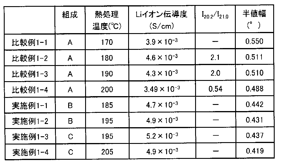
- composition A 20LiI ⁇ 80 (0.75Li 2 S ⁇ 0.25P 2 S 5 ) in terms of mole, and this composition is designated as composition A.
- sulfide glass was vacuum-sealed in a quartz tube, and heat treatment was performed at 170 ° C. Specifically, the sample was put into a furnace previously maintained at 170 ° C. and heat-treated for 3 hours to obtain a sulfide solid electrolyte material that is glass ceramic.
- Comparative Example 1-2 A sulfide solid electrolyte material was obtained in the same manner as Comparative Example 1-1 except that the heat treatment temperature was 180 ° C.
- Comparative Example 1-3 A sulfide solid electrolyte material was obtained in the same manner as Comparative Example 1-1 except that the heat treatment temperature was 190 ° C.
- Example 1-1 Starting from Li 2 S (manufactured by Nippon Kagaku Kogyo Co., Ltd.), P 2 S 5 (manufactured by Aldrich), LiI (manufactured by Nichiho Chemical) and LiBr (manufactured by high purity chemical), 0.572 g of Li 2 S, P 2 S A sulfide solid electrolyte material was obtained in the same manner as Comparative Example 1-1 except that 0.922g of Li, 0.416g of LiI and 0.09g of LiBr were used, and the heat treatment temperature was 185 ° C. It was.
- the composition is 15LiI ⁇ 5LiBr ⁇ 80 (0.75Li 2 S ⁇ 0.25P 2 S 5 ) in terms of mole, and this composition is referred to as composition B.
- Example 1-2 A sulfide solid electrolyte material was obtained in the same manner as in Example 1-1 except that the heat treatment temperature was 195 ° C.
- Example 1-3 Starting from Li 2 S (manufactured by Nippon Kagaku Kogyo Co., Ltd.), P 2 S 5 (manufactured by Aldrich), LiI (manufactured by Nichiho Chemical) and LiBr (manufactured by high purity chemical), 0.580 g of Li 2 S, P 2 S A sulfide solid electrolyte material was prepared in the same manner as in Example 1-1 except that 0.936 g of Li, 0.338 g of LiI and 0.146 g of LiBr were used, and the heat treatment temperature was 195 ° C. Obtained. The composition is 12LiI ⁇ 8LiBr ⁇ 80 (0.75Li 2 S ⁇ 0.25P 2 S 5 ) in terms of mole, and this composition is designated as composition C.
- Example 1-4 A sulfide solid electrolyte material was obtained in the same manner as in Example 1-3, except that the heat treatment temperature was 205 ° C.
- the T c1 of the sulfide glass having compositions A to C was around 190 ° C.
- composition B when composition A and composition B were compared, it was confirmed that in composition B, T cx was shifted to the high temperature side.
- composition C the exothermic peak of T cx and the exothermic peak of T c2 are considered to overlap.
- Li ion conductivity of the sulfide solid electrolyte materials obtained in Comparative Examples 1-1 to 1-4 and Examples 1-1 to 1-4 was measured.
- the sample was cold-pressed at a pressure of 4 ton / cm 2 to prepare a pellet having a diameter of 11.29 mm and a thickness of about 500 ⁇ m.
- the pellets were placed in an inert atmosphere container filled with Ar gas, and measurement was performed.
- Solartron SI1260
- the measurement temperature was adjusted to 25 ° C. in a thermostatic bath. The results are shown in FIG.
- X-ray diffraction measurement X-ray diffraction measurement was performed on the sulfide solid electrolyte materials obtained in Comparative Examples 1-1 to 1-4 and Examples 1-1 to 1-4.
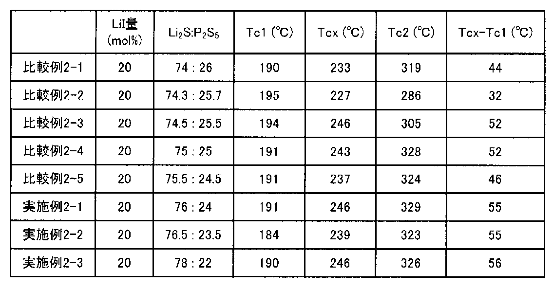
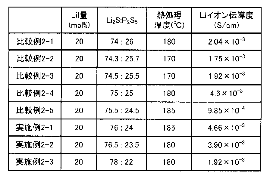
- Comparative Examples 2-1 to 2-5 and Examples 2-1 to 2-3 Comparative Example 1-1 and Li 2 S (manufactured by Nippon Chemical Industry Co., Ltd.), P 2 S 5 (manufactured by Aldrich) and LiI (manufactured by Niho Kagaku) and the heat treatment temperature were set to the conditions shown in Table 4. Similarly, a sulfide solid electrolyte material was obtained.
- Example 3-1 A sulfide solid electrolyte material was obtained in the same manner as Comparative Example 3-4 except that the heat treatment temperature was 175 ° C. and the heat treatment time was 10 hours.
- Example 3-2 A sulfide solid electrolyte material was obtained in the same manner as in Example 3-1, except that the heat treatment time was set to 70 hours.
- Example 3-3 A sulfide solid electrolyte material was obtained in the same manner as in Example 3-1, except that the heat treatment temperature was 185 ° C.
- the T c1 of the sulfide glasses of compositions A and D was around 190 ° C.
- T cx is shifted to a high temperature side, and it is considered that the exothermic peak of T cx and the exothermic peak of T c2 overlap.
- Example 4-1 A sulfide solid electrolyte material was obtained in the same manner as in Reference Example 4-1, except that the heat treatment temperature was 190 ° C.
- Example 4-2 A sulfide solid electrolyte material was obtained in the same manner as in Reference Example 4-1, except that the heat treatment temperature was 200 ° C.
- T c1 of the sulfide glasses of compositions A and E was around 190 ° C.
- T cx is shifted to a high temperature side, and it is considered that the exothermic peak of T cx and the exothermic peak of T c2 overlap.
Landscapes
- Chemical & Material Sciences (AREA)
- Engineering & Computer Science (AREA)
- General Chemical & Material Sciences (AREA)
- Chemical Kinetics & Catalysis (AREA)
- Materials Engineering (AREA)
- Life Sciences & Earth Sciences (AREA)
- Geochemistry & Mineralogy (AREA)
- Organic Chemistry (AREA)
- Electrochemistry (AREA)
- Manufacturing & Machinery (AREA)
- Condensed Matter Physics & Semiconductors (AREA)
- Physics & Mathematics (AREA)
- General Physics & Mathematics (AREA)
- Inorganic Chemistry (AREA)
- Ceramic Engineering (AREA)
- Crystallography & Structural Chemistry (AREA)
- Dispersion Chemistry (AREA)
- Secondary Cells (AREA)
- Conductive Materials (AREA)
- Battery Electrode And Active Subsutance (AREA)
Abstract
Description
まず、本発明の硫化物固体電解質材料について説明する。本発明の硫化物固体電解質材料は、Li、P、I、およびSを有し、CuKα線を用いたX線回折測定において、2θ=20.2°、23.6°にピークを有し、かつ、2θ=21.0°、28.0°にピークを有さず、上記2θ=20.2°のピークの半値幅が、0.51°以下であることを特徴とする。
次に、本発明の硫化物ガラスについて説明する。本発明の硫化物ガラスは、Li、P、I、Br、およびSを有し、CuKα線を用いたX線回折測定において、2θ=20.2°、23.6°にピークを有する高Liイオン伝導相をc1とし、2θ=21.0°、28.0°にピークを有する低Liイオン伝導相をcxとし、示差熱分析において、上記c1の発熱ピークの温度をTc1とし、上記cxの発熱ピークの温度をTcxとした場合に、Tcx-Tc1≧55℃であることを特徴とする。
次に、本発明のリチウム固体電池について説明する。図1は、本発明のリチウム固体電池の一例を示す概略断面図である。図1に示されるリチウム固体電池10は、正極活物質を含有する正極活物質層1と、負極活物質を含有する負極活物質層2と、正極活物質層1および負極活物質層2の間に形成された固体電解質層3と、正極活物質層1の集電を行う正極集電体4と、負極活物質層2の集電を行う負極集電体5と、を有するものである。本発明においては、正極活物質層1、負極活物質層2および固体電解質層3の少なくとも一つが、上記「A.硫化物固体電解質材料」に記載した硫化物固体電解質材料を含有することを大きな特徴とする。
以下、本発明のリチウム固体電池について、構成ごとに説明する。
まず、本発明における正極活物質層について説明する。本発明における正極活物質層は、少なくとも正極活物質を含有する層であり、必要に応じて、固体電解質材料、導電化材および結着材の少なくとも一つをさらに含有していても良い。
次に、本発明における負極活物質層について説明する。本発明における負極活物質層は、少なくとも負極活物質を含有する層であり、必要に応じて、固体電解質材料、導電化材および結着材の少なくとも一つをさらに含有していても良い。
次に、本発明における固体電解質層について説明する。本発明における固体電解質層は、正極活物質層および負極活物質層の間に形成される層であり、固体電解質材料から構成される層である。固体電解質層に含まれる固体電解質材料は、Liイオン伝導性を有するものであれば特に限定されるものではない。
本発明のリチウム固体電池は、上述した正極活物質層、負極活物質層および固体電解質層を少なくとも有するものである。さらに通常は、正極活物質層の集電を行う正極集電体、および負極活物質層の集電を行う負極集電体を有する。正極集電体の材料としては、例えば、SUS、アルミニウム、ニッケル、鉄、チタンおよびカーボン等を挙げることができる。一方、負極集電体の材料としては、例えば、SUS、銅、ニッケルおよびカーボン等を挙げることができる。また、正極集電体および負極集電体の厚さや形状等については、リチウム固体電池の用途等に応じて適宜選択することが好ましい。また、本発明に用いられる電池ケースには、一般的なリチウム固体電池の電池ケースを用いることができる。電池ケースとしては、例えば、SUS製電池ケース等を挙げることができる。
本発明のリチウム固体電池は、一次電池であっても良く、二次電池であっても良いが、中でも、二次電池であることが好ましい。繰り返し充放電でき、例えば、車載用電池として有用だからである。本発明のリチウム固体電池の形状としては、例えば、コイン型、ラミネート型、円筒型および角型等を挙げることができる。
次に、本発明の硫化物固体電解質材料の製造方法について説明する。図2は、本発明の硫化物固体電解質材料の製造方法の一例を示すフローチャートである。図2においては、まず、Li2S、P2S5、LiIおよびLiBrを含有する原料組成物を用意する。次に、原料組成物に対して、メカニカルミリングを行うことにより、Li、PおよびSを有するイオン伝導体(例えば、Li3PS4)と、LiIと、LiBrとから構成される硫化物ガラスを合成する。次に、硫化物ガラスを熱処理し、所望の硫化物固体電解質材料を得る。本発明の硫化物固体電解質材料の製造方法は、Tcx-Tc1≧55℃である硫化物ガラスを用いる点に大きな特徴を有する。この硫化物ガラスに対し、TcxおよびTc1を考慮した熱処理温度および熱処理時間を選択することで、所望の硫化物固体電解質材料が得られる。
以下、本発明の硫化物固体電解質材料の製造方法について、工程ごとに説明する。
本発明における非晶質化工程は、Li2S、P2S5およびLiIを少なくとも含有する原料組成物を非晶質化し、硫化物ガラスを得る工程である。
次に、本発明における熱処理工程について説明する。本発明における熱処理工程は、上記硫化物ガラスを加熱する工程である。
Li2S(日本化学工業製)、P2S5(アルドリッチ製)およびLiI(日宝化学製)を出発原料として、Li2Sを0.558g、P2S5を0.900g、LiIを0.542g秤量し、メノウ乳鉢で5分混合した。その混合物を遊星型ボールミルの容器(45cc、ZrO2製)に投入し、脱水ヘプタン(水分量30ppm以下、4g)を投入し、さらにZrO2ボール(φ=5mm、53g)を投入し、容器を完全に密閉した。この容器を遊星型ボールミル機(フリッチュ製P7)に取り付け、台盤回転数500rpmで、20時間メカニカルミリングを行った。その後、110℃で1時間乾燥することによりヘプタンを除去し、硫化物ガラスを得た。なお、組成はモル表記で20LiI・80(0.75Li2S・0.25P2S5)であり、この組成を組成Aとする。
熱処理温度を180℃としたこと以外は、比較例1-1と同様にして硫化物固体電解質材料を得た。
熱処理温度を190℃としたこと以外は、比較例1-1と同様にして硫化物固体電解質材料を得た。
熱処理温度を200℃としたこと以外は、比較例1-1と同様にして硫化物固体電解質材料を得た。
Li2S(日本化学工業製)、P2S5(アルドリッチ製)、LiI(日宝化学製)およびLiBr(高純度化学製)を出発原料として、Li2Sを0.572g、P2S5を0.922g、LiIを0.416g、LiBrを0.09g用いたこと、および、熱処理温度を185℃としたこと以外は、比較例1-1と同様にして硫化物固体電解質材料を得た。なお、組成はモル表記で15LiI・5LiBr・80(0.75Li2S・0.25P2S5)であり、この組成を組成Bとする。
熱処理温度を195℃としたこと以外は、実施例1-1と同様にして、硫化物固体電解質材料を得た。
Li2S(日本化学工業製)、P2S5(アルドリッチ製)、LiI(日宝化学製)およびLiBr(高純度化学製)を出発原料として、Li2Sを0.580g、P2S5を0.936g、LiIを0.338g、LiBrを0.146g用いたこと、および、熱処理温度を195℃としたこと以外は、実施例1-1と同様にして、硫化物固体電解質材料を得た。なお、組成はモル表記で12LiI・8LiBr・80(0.75Li2S・0.25P2S5)であり、この組成を組成Cとする。
熱処理温度を205℃としたこと以外は、実施例1-3と同様にして、硫化物固体電解質材料を得た。
(DTA測定)
組成A~Cの硫化物ガラスについてDTA分析を行った。測定にはTG-DTA装置(Thermo plus EVO、リガク製)を用いた。アルミ製の試料皿を用い、参照試料としてα-Al2O3粉末を用いた。測定試料を20mg~26mg用い、Arガス雰囲気において室温から400℃まで10℃/minで昇温し、DTA分析を行った。なお、ここでは発熱ピークのピーク値を読み取った。その結果を図3および表1に示す。

比較例1-1~1-4および実施例1-1~1-4で得られた硫化物固体電解質材料について、Liイオン伝導度の測定を行った。まず、試料を4ton/cm2の圧力でコールドプレスすることで、φ11.29mm、厚さ約500μmのペレットを作製した。次に、ペレットを、Arガスで充填した不活性雰囲気の容器内に設置して測定を行った。測定には、東陽テクニカ社製のソーラトロン(SI1260)を用いた。また、恒温槽で測定温度を25℃に調整した。その結果を図4および表2に示す。
比較例1-1~1-4および実施例1-1~1-4で得られた硫化物固体電解質材料について、X線回折測定を行った。リガク製のXRD装置(RINT-UltimaIII)を用いて、粉末XRD測定を行った。ドーム状の冶具中に試料を設置し、Arガスの不活性雰囲気で2θ=10°~60°の範囲で測定した。スキャンスピードは5°/min、サンプリング幅は0.02°とした。また、2θ=20.2°のピークの半値幅を求めた。その結果を図5、図6および表2に示す。
Li2S(日本化学工業製)、P2S5(アルドリッチ製)およびLiI(日宝化学製)の割合および熱処理温度を、表4に示す条件としたこと以外は、比較例1-1と同様にして、硫化物固体電解質材料を得た。
(DTA測定)
比較例2-1~2-5および実施例2-1~2-3における合成の途中で得られた硫化物ガラスについてDTA分析を行った。測定条件は、上記と同様である。その結果を図7および表3に示す。
比較例2-1~2-5および実施例2-1~2-3で得られた硫化物固体電解質材料について、Liイオン伝導度測定およびX線回折測定を行った。測定条件は、上記と同様である。その結果を図8および表4に示す。
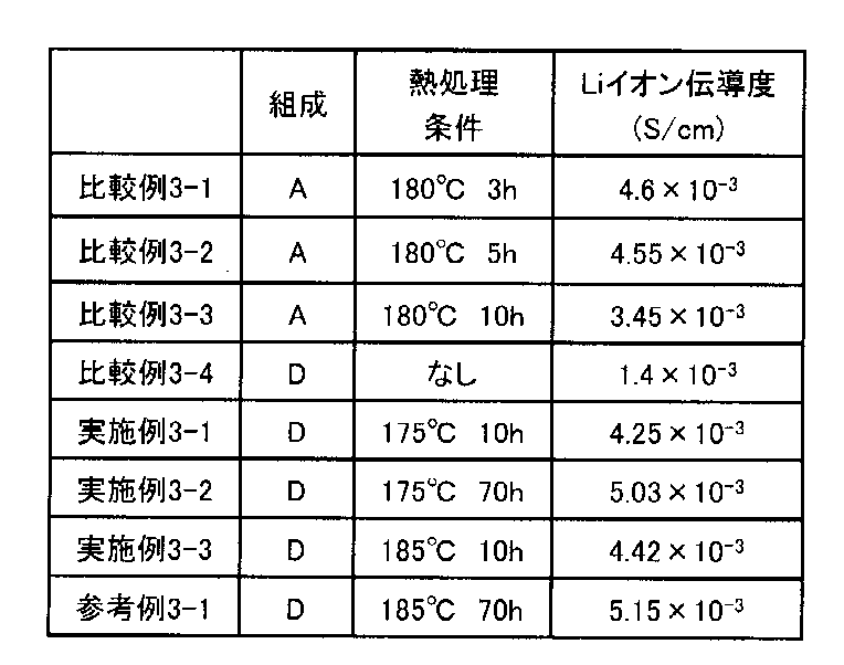
上述した比較例1-2と同様にして硫化物固体電解質材料を得た。
熱処理時間を5時間としたこと以外は、比較例3-1と同様にして硫化物固体電解質材料を得た。
熱処理時間を10時間としたこと以外は、比較例3-1と同様にして硫化物固体電解質材料を得た。
Li2S(日本化学工業製)、P2S5(アルドリッチ製)、LiI(日宝化学製)およびLiBr(高純度化学製)を出発原料として、Li2Sを0.586g、P2S5を0.945g、LiIを0.284g、LiBrを0.185g用いたこと、および、熱処理温度を行わなかったこと以外は、比較例3-1と同様にして硫化物固体電解質材料(硫化物ガラス)を得た。なお、組成はモル表記で10LiI・10LiBr・80(0.75Li2S・0.25P2S5)であり、この組成を組成Dとする。
熱処理温度を175℃としたこと、および、熱処理時間を10時間としたこと以外は、比較例3-4と同様にして硫化物固体電解質材料を得た。
熱処理時間を70時間としたこと以外は、実施例3-1と同様にして硫化物固体電解質材料を得た。
熱処理温度を185℃としたこと以外は、実施例3-1と同様にして硫化物固体電解質材料を得た。
熱処理時間を70時間としたこと以外は、実施例3-3と同様にして硫化物固体電解質材料を得た。
(DTA測定)
組成A、Dの硫化物ガラスについてDTA分析を行った。測定条件は、上記と同様である。その結果を図9および表5に示す。

比較例3-1~3-4、実施例3-1~3-3および参考例3-1で得られた硫化物固体電解質材料について、Liイオン伝導度測定およびX線回折測定を行った。測定条件は、上記と同様である。その結果を図10~図12および表6に示す。
上述した比較例1-1~1-4と同様にして、それぞれ硫化物固体電解質材料を得た。
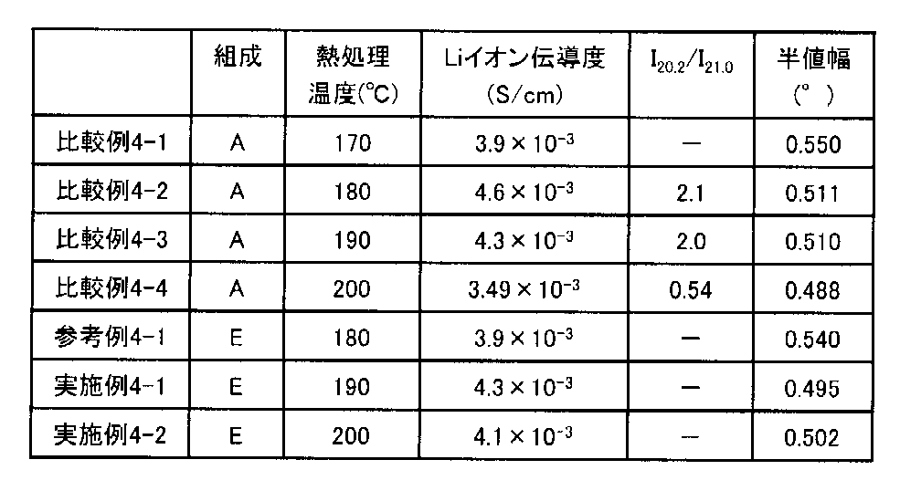
Li2S(日本化学工業製)、P2S5(アルドリッチ製)、LiI(日宝化学製)およびLiCl(高純度化学製)を出発原料として、Li2Sを0.585g、P2S5を0.944g、LiIを0.426g、LiClを0.045g用いたこと以外は、比較例4-2と同様にして硫化物固体電解質材料を得た。なお、組成はモル表記で15LiI・5LiCl・80(0.75Li2S・0.25P2S5)であり、この組成を組成Eとする。
熱処理温度を190℃としたこと以外は、参考例4-1と同様にして硫化物固体電解質材料を得た。
熱処理温度を200℃としたこと以外は、参考例4-1と同様にして硫化物固体電解質材料を得た。
(DTA測定)
組成A、Eの硫化物ガラスについてDTA分析を行った。測定条件は、上記と同様である。その結果を表7に示す。

参考例4-1および実施例4-1、4-2で得られた硫化物固体電解質材料について、Liイオン伝導度測定およびX線回折測定を行った。測定条件は、上記と同様である。その結果を図13、図14および表8に示す。
2 … 負極活物質層
3 … 固体電解質層
4 … 正極集電体
5 … 負極集電体
10 … リチウム固体電池
Claims (8)
- Li、P、I、およびSを有し、
CuKα線を用いたX線回折測定において、2θ=20.2°、23.6°にピークを有し、かつ、2θ=21.0°、28.0°にピークを有さず、前記2θ=20.2°のピークの半値幅が、0.51°以下であることを特徴とする硫化物固体電解質材料。 - Li、P、およびSを有するイオン伝導体と、LiIと、LiBrおよびLiClの少なくとも一方と、から構成されていることを特徴とする請求項1に記載の硫化物固体電解質材料。
- 前記LiBrを有し、
LiBr/(LiI+LiBr)が、25mol%~50mol%の範囲内であることを特徴とする請求項2に記載の硫化物固体電解質材料。 - Li2S、P2S5およびLiIを少なくとも含有する原料組成物を用いてなり、
Li2S/(Li2S+P2S5)が、76mol%~78mol%の範囲内であることを特徴とする請求項1から請求項3までのいずれかの請求項に記載の硫化物固体電解質材料。 - Li、P、I、Br、およびSを有し、
CuKα線を用いたX線回折測定において、2θ=20.2°、23.6°にピークを有する高Liイオン伝導相をc1とし、2θ=21.0°、28.0°にピークを有する低Liイオン伝導相をcxとし、示差熱分析において、前記c1の発熱ピークの温度をTc1とし、前記cxの発熱ピークの温度をTcxとした場合に、Tcx-Tc1≧55℃であることを特徴とする硫化物ガラス。 - Li、P、およびSを有するイオン伝導体と、LiIと、LiBrと、から構成され、
LiBr/(LiI+LiBr)が、25mol%~50mol%の範囲内であることを特徴とする請求項5に記載の硫化物ガラス。 - 正極活物質を含有する正極活物質層と、負極活物質を含有する負極活物質層と、前記正極活物質層および前記負極活物質層の間に形成された固体電解質層と、を有するリチウム固体電池であって、
前記正極活物質層、前記負極活物質層および前記固体電解質層の少なくとも一つが、請求項1から請求項4までのいずれかの請求項に記載の硫化物固体電解質材料を含有することを特徴とするリチウム固体電池。 - 請求項1から請求項4までのいずれかの請求項に記載の硫化物固体電解質材料の製造方法であって、
Li2S、P2S5、およびLiIを少なくとも含有する原料組成物を非晶質化し、硫化物ガラスを得る非晶質化工程と、
前記硫化物ガラスを加熱する熱処理工程と、
を有し、
CuKα線を用いたX線回折測定において、2θ=20.2°、23.6°にピークを有する高Liイオン伝導相をc1とし、2θ=21.0°、28.0°にピークを有する低Liイオン伝導相をcxとし、示差熱分析において、前記c1の発熱ピークの温度をTc1とし、前記cxの発熱ピークの温度をTcxとした場合に、Tcx-Tc1≧55℃である前記硫化物ガラスを用いることを特徴とする硫化物固体電解質材料の製造方法。
Priority Applications (4)
| Application Number | Priority Date | Filing Date | Title |
|---|---|---|---|
| EP14817077.2A EP3016198B1 (en) | 2013-06-28 | 2014-05-26 | Sulfide solid electrolyte material, sulfide glass, solid-state lithium battery, and method for producing sulfide solid electrolyte material |
| US14/897,332 US11011775B2 (en) | 2013-06-28 | 2014-05-26 | Sulfide solid electrolyte material, sulfide glass, solid state lithium battery, and method for producing sulfide solid electrolyte material |
| CN201480035260.0A CN105324878B (zh) | 2013-06-28 | 2014-05-26 | 硫化物固体电解质材料、硫化物玻璃、锂固体电池和硫化物固体电解质材料的制造方法 |
| KR1020157035601A KR101723331B1 (ko) | 2013-06-28 | 2014-05-26 | 황화물 고체 전해질 재료, 황화물 유리, 리튬 고체 전지, 및, 황화물 고체 전해질 재료의 제조 방법 |
Applications Claiming Priority (2)
| Application Number | Priority Date | Filing Date | Title |
|---|---|---|---|
| JP2013-137329 | 2013-06-28 | ||
| JP2013137329A JP6003831B2 (ja) | 2013-06-28 | 2013-06-28 | 硫化物固体電解質材料、硫化物ガラス、リチウム固体電池、および、硫化物固体電解質材料の製造方法 |
Publications (1)
| Publication Number | Publication Date |
|---|---|
| WO2014208239A1 true WO2014208239A1 (ja) | 2014-12-31 |
Family
ID=52141591
Family Applications (1)
| Application Number | Title | Priority Date | Filing Date |
|---|---|---|---|
| PCT/JP2014/063831 Ceased WO2014208239A1 (ja) | 2013-06-28 | 2014-05-26 | 硫化物固体電解質材料、硫化物ガラス、リチウム固体電池、および、硫化物固体電解質材料の製造方法 |
Country Status (6)
| Country | Link |
|---|---|
| US (1) | US11011775B2 (ja) |
| EP (1) | EP3016198B1 (ja) |
| JP (1) | JP6003831B2 (ja) |
| KR (1) | KR101723331B1 (ja) |
| CN (1) | CN105324878B (ja) |
| WO (1) | WO2014208239A1 (ja) |
Cited By (7)
| Publication number | Priority date | Publication date | Assignee | Title |
|---|---|---|---|---|
| CN105938894A (zh) * | 2015-03-05 | 2016-09-14 | 丰田自动车株式会社 | 电极体的制造方法 |
| JP2016207354A (ja) * | 2015-04-17 | 2016-12-08 | 出光興産株式会社 | 硫化物固体電解質の製造方法 |
| JP2017152348A (ja) * | 2016-02-26 | 2017-08-31 | トヨタ自動車株式会社 | 複合活物質の製造方法 |
| US10020535B2 (en) | 2015-12-01 | 2018-07-10 | Idemitsu Kosan Co., Ltd. | Method for producing sulfide solid electrolyte |
| JP2018170107A (ja) * | 2017-03-29 | 2018-11-01 | トヨタ自動車株式会社 | 全固体リチウムイオン二次電池用負極及びその負極を備える全固体リチウムイオン二次電池 |
| US11183708B2 (en) | 2015-04-17 | 2021-11-23 | Idemitsu Kosan Co., Ltd. | Method for producing sulfide solid electrolyte and sulfur-based material |
| US12586814B2 (en) | 2021-12-27 | 2026-03-24 | Idemitsu Kosan Co., Ltd. | Method of producing sulfide solid electrolyte and method for producing electrode mixture |
Families Citing this family (64)
| Publication number | Priority date | Publication date | Assignee | Title |
|---|---|---|---|---|
| JP2016141574A (ja) * | 2015-01-29 | 2016-08-08 | 出光興産株式会社 | 固体電解質の製造方法 |
| EP3298643B1 (en) * | 2015-05-21 | 2019-06-12 | Basf Se | Glass-ceramic electrolytes for lithium-sulfur batteries |
| JP6384467B2 (ja) * | 2015-12-18 | 2018-09-05 | トヨタ自動車株式会社 | リチウム固体電池 |
| JP6531674B2 (ja) | 2016-02-26 | 2019-06-19 | トヨタ自動車株式会社 | 硫化物固体電解質材料、リチウム固体電池および硫化物固体電解質材料の製造方法 |
| CN115036565B (zh) * | 2016-08-04 | 2025-02-28 | 松下知识产权经营株式会社 | 固体电解质材料和电池 |
| CN109526242B (zh) * | 2016-08-10 | 2022-04-15 | 出光兴产株式会社 | 硫化物固体电解质 |
| CN109641780A (zh) * | 2016-08-17 | 2019-04-16 | Agc株式会社 | 玻璃 |
| JP6679736B2 (ja) | 2016-09-12 | 2020-04-15 | 出光興産株式会社 | 硫化物固体電解質 |
| CN109937506A (zh) * | 2016-11-15 | 2019-06-25 | 株式会社村田制作所 | 锂离子传导体、全固体电池、电子设备、电子卡、可穿戴设备以及电动车辆 |
| EP3601159A4 (en) * | 2017-03-29 | 2020-11-25 | Solid Power, Inc. | SOLID ELECTROLYTE MATERIAL AND SOLID ELECTROLYTE BATTERY MADE WITH THIS LATEST |
| JP6589940B2 (ja) * | 2017-06-06 | 2019-10-16 | トヨタ自動車株式会社 | 硫化物固体電解質材料の製造方法 |
| WO2019003986A1 (ja) | 2017-06-29 | 2019-01-03 | 出光興産株式会社 | 硫化物固体電解質 |
| EP3667800B1 (en) * | 2017-08-10 | 2024-10-09 | Idemitsu Kosan Co.,Ltd. | Sulfide solid electrolyte |
| US10985407B2 (en) | 2017-11-21 | 2021-04-20 | Samsung Electronics Co., Ltd. | All-solid-state secondary battery including anode active material alloyable with lithium and method of charging the same |
| WO2019135347A1 (ja) | 2018-01-05 | 2019-07-11 | パナソニックIpマネジメント株式会社 | 固体電解質材料、および、電池 |
| WO2019135328A1 (ja) | 2018-01-05 | 2019-07-11 | パナソニックIpマネジメント株式会社 | 固体電解質材料、および、電池 |
| WO2019135316A1 (ja) * | 2018-01-05 | 2019-07-11 | パナソニックIpマネジメント株式会社 | 固体電解質材料、および、電池 |
| JP7611524B2 (ja) | 2018-01-05 | 2025-01-10 | パナソニックIpマネジメント株式会社 | 固体電解質材料、および、電池 |
| JPWO2019135318A1 (ja) | 2018-01-05 | 2021-01-14 | パナソニックIpマネジメント株式会社 | 固体電解質材料、および、電池 |
| EP3736834A4 (en) * | 2018-01-05 | 2021-03-10 | Panasonic Intellectual Property Management Co., Ltd. | SOLID ELECTROLYTE MATERIAL, AND BATTERY |
| JP7281672B2 (ja) | 2018-01-05 | 2023-05-26 | パナソニックIpマネジメント株式会社 | 電池 |
| WO2019135345A1 (ja) | 2018-01-05 | 2019-07-11 | パナソニックIpマネジメント株式会社 | 固体電解質材料、および、電池 |
| EP3736832B1 (en) * | 2018-01-05 | 2024-04-10 | Panasonic Intellectual Property Management Co., Ltd. | Solid electrolyte material, and battery |
| JP7228816B2 (ja) | 2018-01-05 | 2023-02-27 | パナソニックIpマネジメント株式会社 | 正極材料、および、電池 |
| EP3736823A4 (en) * | 2018-01-05 | 2021-03-10 | Panasonic Intellectual Property Management Co., Ltd. | SOLID ELECTROLYTE AND BATTERY |
| WO2019135336A1 (ja) * | 2018-01-05 | 2019-07-11 | パナソニックIpマネジメント株式会社 | 固体電解質材料、および、電池 |
| WO2019135320A1 (ja) | 2018-01-05 | 2019-07-11 | パナソニックIpマネジメント株式会社 | 固体電解質材料、および、電池 |
| CN111557057B (zh) | 2018-01-26 | 2024-04-19 | 松下知识产权经营株式会社 | 正极材料和使用它的电池 |
| CN111587508A (zh) | 2018-01-26 | 2020-08-25 | 松下知识产权经营株式会社 | 电池 |
| JP7217433B2 (ja) | 2018-01-26 | 2023-02-03 | パナソニックIpマネジメント株式会社 | 正極材料およびそれを用いた電池 |
| CN111566756B (zh) | 2018-01-26 | 2022-03-08 | 松下知识产权经营株式会社 | 固体电解质材料和电池 |
| CN111566757B (zh) * | 2018-01-26 | 2022-08-12 | 松下知识产权经营株式会社 | 固体电解质材料和电池 |
| US11437643B2 (en) | 2018-02-20 | 2022-09-06 | Samsung Electronics Co., Ltd. | All-solid-state secondary battery |
| US11127974B2 (en) | 2018-05-14 | 2021-09-21 | Samsung Electronics Co., Ltd. | Method of preparing sulfide-based solid electrolyte, sulfide-based solid electrolyte prepared therefrom, and solid secondary battery including the sulfide electrolyte |
| CN108899580A (zh) * | 2018-07-02 | 2018-11-27 | 中国科学院宁波材料技术与工程研究所 | 一种锂离子固体导体、其制备方法及全固态锂电池 |
| CN112424886B (zh) * | 2018-07-17 | 2023-02-28 | 出光兴产株式会社 | 固体电解质的制造方法 |
| US11325096B2 (en) * | 2018-07-24 | 2022-05-10 | Toyota Motor Engineering & Manufacturing North America, Inc. | Microwave synthesis of lithium thiophosphate composite materials |
| JP7010176B2 (ja) * | 2018-08-29 | 2022-01-26 | トヨタ自動車株式会社 | ニオブ酸リチウム、及びそれの製造方法 |
| WO2020058529A1 (en) * | 2018-09-21 | 2020-03-26 | Philipps-Universität Marburg | Amorphous solid li+ electrolyte, process for production of the amorphous solid electrolyte and usage of the amorphous solid electrolyte |
| US11984552B2 (en) | 2018-11-16 | 2024-05-14 | Samsung Electronics Co., Ltd. | Phase-transition solid electrolyte material and all solid secondary battery including the same |
| JP7429869B2 (ja) | 2018-11-29 | 2024-02-09 | パナソニックIpマネジメント株式会社 | 負極材料、および、電池 |
| WO2020110480A1 (ja) | 2018-11-29 | 2020-06-04 | パナソニックIpマネジメント株式会社 | 負極材料、電池、および電池の製造方法 |
| JP7196625B2 (ja) | 2019-01-17 | 2022-12-27 | トヨタ自動車株式会社 | 硫化物固体電解質粒子及びその製造方法、並びに、全固体電池 |
| JP7156048B2 (ja) | 2019-01-17 | 2022-10-19 | トヨタ自動車株式会社 | 硫化物固体電解質粒子、及び、全固体電池 |
| US11824155B2 (en) | 2019-05-21 | 2023-11-21 | Samsung Electronics Co., Ltd. | All-solid lithium secondary battery and method of charging the same |
| US11799126B2 (en) | 2019-05-31 | 2023-10-24 | Samsung Electronics Co., Ltd. | Method of preparing solid electrolyte and all-solid battery including solid electrolyte prepared by the method |
| KR102298979B1 (ko) * | 2019-08-09 | 2021-09-06 | 현대자동차주식회사 | 황화물계 고체 전해질 제조 방법 및 이로부터 제조된 황화물계 고체 전해질 |
| JP7143834B2 (ja) * | 2019-11-14 | 2022-09-29 | トヨタ自動車株式会社 | 電極の製造方法、電極、および全固体電池 |
| JP7243662B2 (ja) * | 2020-02-21 | 2023-03-22 | トヨタ自動車株式会社 | 硫化物固体電解質の製造方法 |
| JP7226371B2 (ja) * | 2020-02-21 | 2023-02-21 | トヨタ自動車株式会社 | 全固体電池 |
| EP4117053A4 (en) | 2020-03-06 | 2025-05-14 | Toyota Jidosha Kabushiki Kaisha | SOLID-STATE BATTERY |
| US11928472B2 (en) | 2020-09-26 | 2024-03-12 | Intel Corporation | Branch prefetch mechanisms for mitigating frontend branch resteers |
| KR102401475B1 (ko) * | 2020-09-28 | 2022-05-25 | 주식회사 포스코제이케이솔리드솔루션 | 전고체 리튬 이차전지용 황화물계 고체전해질 및 황화물계 고체전해질의 제조방법 |
| US20230378524A1 (en) * | 2020-09-28 | 2023-11-23 | Posco Jk Solid Solution Co., Ltd. | Sulfide-based solid electrolyte for all-solid lithium secondary battery and method for preparing sulfide-based solid electrolyte |
| US20220131184A1 (en) * | 2020-10-23 | 2022-04-28 | Battelle Memorial Institute | Air-stable solid-state sulfide electrolyte |
| KR102455736B1 (ko) * | 2020-11-25 | 2022-10-19 | 한국과학기술연구원 | 할로겐 원소가 도입된 리튬 이차전지용 황화물 유리질계 고체전해질 |
| US12182317B2 (en) | 2021-02-13 | 2024-12-31 | Intel Corporation | Region-based deterministic memory safety |
| CN115312839A (zh) * | 2021-05-07 | 2022-11-08 | 迪吉亚节能科技股份有限公司 | 固态电解质材料、其制备方法及使用该固态电解质材料的极片、电池芯 |
| TWI764711B (zh) * | 2021-05-07 | 2022-05-11 | 迪吉亞節能科技股份有限公司 | 極片之製備方法、使用該極片之電池芯及該電池芯之製備方法 |
| US12504891B2 (en) | 2021-06-24 | 2025-12-23 | Intel Corporation | Zero-redundancy tag storage for bucketed allocators |
| US12235791B2 (en) | 2021-08-23 | 2025-02-25 | Intel Corporation | Loop driven region based frontend translation control for performant and secure data-space guided micro-sequencing |
| JP7597071B2 (ja) * | 2022-04-15 | 2024-12-10 | トヨタ自動車株式会社 | 電極および全固体電池 |
| JP7597072B2 (ja) * | 2022-04-15 | 2024-12-10 | トヨタ自動車株式会社 | 電極および全固体電池 |
| WO2025159169A1 (ja) * | 2024-01-26 | 2025-07-31 | 株式会社Gsユアサ | 硫化物固体電解質、硫化物固体電解質用材料、硫化物固体電解質の製造方法、及び蓄電素子 |
Citations (6)
| Publication number | Priority date | Publication date | Assignee | Title |
|---|---|---|---|---|
| JPS628467A (ja) | 1985-06-28 | 1987-01-16 | ユニオン、カ−バイド、コ−ポレ−シヨン | 四元ガラス質固体リチウムカチオン伝導性電解質 |
| JPH05306119A (ja) * | 1992-05-07 | 1993-11-19 | Matsushita Electric Ind Co Ltd | 非晶質リチウムイオン伝導性固体電解質並びにその合成法 |
| JPH05306117A (ja) | 1992-05-07 | 1993-11-19 | Matsushita Electric Ind Co Ltd | 非晶質リチウムイオン伝導性固体電解質並びにその合成法 |
| JPH1173993A (ja) * | 1997-06-10 | 1999-03-16 | Samsung Display Devices Co Ltd | ガラス−高分子複合電解質及びその製造方法及び電池 |
| JP2012048971A (ja) | 2010-08-26 | 2012-03-08 | Toyota Motor Corp | 硫化物固体電解質材料、正極体およびリチウム固体電池 |
| JP2013016423A (ja) | 2011-07-06 | 2013-01-24 | Toyota Motor Corp | 硫化物固体電解質材料、リチウム固体電池、および、硫化物固体電解質材料の製造方法 |
Family Cites Families (7)
| Publication number | Priority date | Publication date | Assignee | Title |
|---|---|---|---|---|
| JPH0536117A (ja) | 1991-07-29 | 1993-02-12 | Nec Corp | 光デイスクおよびその製造方法 |
| JP4813767B2 (ja) | 2004-02-12 | 2011-11-09 | 出光興産株式会社 | リチウムイオン伝導性硫化物系結晶化ガラス及びその製造方法 |
| JP5158008B2 (ja) * | 2009-04-28 | 2013-03-06 | トヨタ自動車株式会社 | 全固体電池 |
| JP2011060649A (ja) * | 2009-09-11 | 2011-03-24 | Toyota Motor Corp | 電極活物質層、全固体電池、電極活物質層の製造方法および全固体電池の製造方法 |
| JP5521899B2 (ja) | 2010-08-26 | 2014-06-18 | トヨタ自動車株式会社 | 硫化物固体電解質材料およびリチウム固体電池 |
| US9991554B2 (en) * | 2012-07-10 | 2018-06-05 | Idemitsu Kosan Co., Ltd. | Sulfide glass, and method for producing sulfide glass ceramic |
| JP2014029796A (ja) | 2012-07-31 | 2014-02-13 | Kansai Electric Power Co Inc:The | リチウムイオン伝導性結晶化固体電解質およびリチウムイオン伝導性結晶化固体電解質の製造方法 |
-
2013
- 2013-06-28 JP JP2013137329A patent/JP6003831B2/ja active Active
-
2014
- 2014-05-26 US US14/897,332 patent/US11011775B2/en active Active
- 2014-05-26 EP EP14817077.2A patent/EP3016198B1/en active Active
- 2014-05-26 CN CN201480035260.0A patent/CN105324878B/zh active Active
- 2014-05-26 WO PCT/JP2014/063831 patent/WO2014208239A1/ja not_active Ceased
- 2014-05-26 KR KR1020157035601A patent/KR101723331B1/ko active Active
Patent Citations (6)
| Publication number | Priority date | Publication date | Assignee | Title |
|---|---|---|---|---|
| JPS628467A (ja) | 1985-06-28 | 1987-01-16 | ユニオン、カ−バイド、コ−ポレ−シヨン | 四元ガラス質固体リチウムカチオン伝導性電解質 |
| JPH05306119A (ja) * | 1992-05-07 | 1993-11-19 | Matsushita Electric Ind Co Ltd | 非晶質リチウムイオン伝導性固体電解質並びにその合成法 |
| JPH05306117A (ja) | 1992-05-07 | 1993-11-19 | Matsushita Electric Ind Co Ltd | 非晶質リチウムイオン伝導性固体電解質並びにその合成法 |
| JPH1173993A (ja) * | 1997-06-10 | 1999-03-16 | Samsung Display Devices Co Ltd | ガラス−高分子複合電解質及びその製造方法及び電池 |
| JP2012048971A (ja) | 2010-08-26 | 2012-03-08 | Toyota Motor Corp | 硫化物固体電解質材料、正極体およびリチウム固体電池 |
| JP2013016423A (ja) | 2011-07-06 | 2013-01-24 | Toyota Motor Corp | 硫化物固体電解質材料、リチウム固体電池、および、硫化物固体電解質材料の製造方法 |
Cited By (9)
| Publication number | Priority date | Publication date | Assignee | Title |
|---|---|---|---|---|
| CN105938894A (zh) * | 2015-03-05 | 2016-09-14 | 丰田自动车株式会社 | 电极体的制造方法 |
| US10608239B2 (en) | 2015-03-05 | 2020-03-31 | Toyota Jidosha Kabushiki Kaisha | Method for producing electrode body |
| JP2016207354A (ja) * | 2015-04-17 | 2016-12-08 | 出光興産株式会社 | 硫化物固体電解質の製造方法 |
| US11183708B2 (en) | 2015-04-17 | 2021-11-23 | Idemitsu Kosan Co., Ltd. | Method for producing sulfide solid electrolyte and sulfur-based material |
| US10020535B2 (en) | 2015-12-01 | 2018-07-10 | Idemitsu Kosan Co., Ltd. | Method for producing sulfide solid electrolyte |
| JP2017152348A (ja) * | 2016-02-26 | 2017-08-31 | トヨタ自動車株式会社 | 複合活物質の製造方法 |
| US10199645B2 (en) * | 2016-02-26 | 2019-02-05 | Toyota Jidosha Kabushiki Kaisha | Producing method for composite active material |
| JP2018170107A (ja) * | 2017-03-29 | 2018-11-01 | トヨタ自動車株式会社 | 全固体リチウムイオン二次電池用負極及びその負極を備える全固体リチウムイオン二次電池 |
| US12586814B2 (en) | 2021-12-27 | 2026-03-24 | Idemitsu Kosan Co., Ltd. | Method of producing sulfide solid electrolyte and method for producing electrode mixture |
Also Published As
| Publication number | Publication date |
|---|---|
| EP3016198A4 (en) | 2016-06-29 |
| US20160149259A1 (en) | 2016-05-26 |
| CN105324878A (zh) | 2016-02-10 |
| CN105324878B (zh) | 2017-06-30 |
| KR20160010555A (ko) | 2016-01-27 |
| KR101723331B1 (ko) | 2017-04-04 |
| EP3016198A1 (en) | 2016-05-04 |
| JP6003831B2 (ja) | 2016-10-05 |
| JP2015011901A (ja) | 2015-01-19 |
| EP3016198B1 (en) | 2018-05-16 |
| US11011775B2 (en) | 2021-05-18 |
Similar Documents
| Publication | Publication Date | Title |
|---|---|---|
| JP6003831B2 (ja) | 硫化物固体電解質材料、硫化物ガラス、リチウム固体電池、および、硫化物固体電解質材料の製造方法 | |
| JP5443445B2 (ja) | 硫化物固体電解質材料、リチウム固体電池、および、硫化物固体電解質材料の製造方法 | |
| JP5553004B2 (ja) | 硫化物固体電解質材料、リチウム固体電池、および硫化物固体電解質材料の製造方法 | |
| CN105914395B (zh) | 硫化物固体电解质材料、电池和硫化物固体电解质材料的制造方法 | |
| JP6077403B2 (ja) | 硫化物固体電解質材料の製造方法 | |
| JP6044588B2 (ja) | 硫化物固体電解質材料、電池および硫化物固体電解質材料の製造方法 | |
| JP6044587B2 (ja) | 硫化物固体電解質材料、電池および硫化物固体電解質材料の製造方法 | |
| JP5757284B2 (ja) | 硫化物固体電解質材料、リチウム固体電池、および、硫化物固体電解質材料の製造方法 | |
| KR101727806B1 (ko) | 황화물 고체 전해질 재료, 전지 및 황화물 고체 전해질 재료의 제조 방법 | |
| JP5857912B2 (ja) | 硫化物固体電解質材料の製造方法 | |
| JP5877401B2 (ja) | 硫化物固体電解質材料の製造方法、及び当該方法により製造された硫化物固体電解質材料を含むリチウム固体電池 | |
| JP5594253B2 (ja) | 硫化物固体電解質材料、リチウム固体電池、および、硫化物固体電解質材料の製造方法 | |
| JP2015076316A (ja) | 硫化物固体電解質材料 | |
| JP6131851B2 (ja) | 硫化物固体電解質材料の製造方法 | |
| JP2014089971A (ja) | 硫化物固体電解質材料、リチウム固体電池、および、硫化物固体電解質材料の製造方法 | |
| JP6070468B2 (ja) | 硫化物固体電解質材料 | |
| JP6256980B2 (ja) | 硫化物固体電解質材料、電池および硫化物固体電解質材料の製造方法 | |
| JP2014127387A (ja) | 硫化物固体電解質材料の製造方法およびリチウム固体電池 | |
| JP2015069855A (ja) | 硫化物固体電解質材料 | |
| JP2016062720A (ja) | 硫化物固体電解質材料およびリチウム固体電池 |
Legal Events
| Date | Code | Title | Description |
|---|---|---|---|
| WWE | Wipo information: entry into national phase |
Ref document number: 201480035260.0 Country of ref document: CN |
|
| 121 | Ep: the epo has been informed by wipo that ep was designated in this application |
Ref document number: 14817077 Country of ref document: EP Kind code of ref document: A1 |
|
| WWE | Wipo information: entry into national phase |
Ref document number: 14897332 Country of ref document: US |
|
| ENP | Entry into the national phase |
Ref document number: 20157035601 Country of ref document: KR Kind code of ref document: A |
|
| WWE | Wipo information: entry into national phase |
Ref document number: 2014817077 Country of ref document: EP |
|
| NENP | Non-entry into the national phase |
Ref country code: DE |