WO2019135320A1 - 固体電解質材料、および、電池 - Google Patents
固体電解質材料、および、電池 Download PDFInfo
- Publication number
- WO2019135320A1 WO2019135320A1 PCT/JP2018/041897 JP2018041897W WO2019135320A1 WO 2019135320 A1 WO2019135320 A1 WO 2019135320A1 JP 2018041897 W JP2018041897 W JP 2018041897W WO 2019135320 A1 WO2019135320 A1 WO 2019135320A1
- Authority
- WO
- WIPO (PCT)
- Prior art keywords
- solid electrolyte
- electrolyte material
- battery
- positive electrode
- negative electrode
- Prior art date
Links
- 239000007784 solid electrolyte Substances 0.000 title claims abstract description 117
- 239000000463 material Substances 0.000 title claims abstract description 85
- 229910052782 aluminium Inorganic materials 0.000 claims abstract description 7
- 229910052733 gallium Inorganic materials 0.000 claims abstract description 6
- 229910052797 bismuth Inorganic materials 0.000 claims abstract description 4
- 229910052706 scandium Inorganic materials 0.000 claims abstract description 4
- 239000003792 electrolyte Substances 0.000 claims description 18
- 239000000203 mixture Substances 0.000 claims description 18
- 239000002245 particle Substances 0.000 description 35
- 150000002500 ions Chemical class 0.000 description 19
- KWGKDLIKAYFUFQ-UHFFFAOYSA-M lithium chloride Chemical compound [Li+].[Cl-] KWGKDLIKAYFUFQ-UHFFFAOYSA-M 0.000 description 18
- 239000000843 powder Substances 0.000 description 16
- 229910003002 lithium salt Inorganic materials 0.000 description 15
- 159000000002 lithium salts Chemical class 0.000 description 15
- -1 etc.) Inorganic materials 0.000 description 14
- 239000007773 negative electrode material Substances 0.000 description 14
- 239000007774 positive electrode material Substances 0.000 description 14
- HBBGRARXTFLTSG-UHFFFAOYSA-N Lithium ion Chemical compound [Li+] HBBGRARXTFLTSG-UHFFFAOYSA-N 0.000 description 13
- 229910001416 lithium ion Inorganic materials 0.000 description 13
- 239000002994 raw material Substances 0.000 description 13
- AMXOYNBUYSYVKV-UHFFFAOYSA-M lithium bromide Chemical compound [Li+].[Br-] AMXOYNBUYSYVKV-UHFFFAOYSA-M 0.000 description 8
- 238000000034 method Methods 0.000 description 8
- 239000003125 aqueous solvent Substances 0.000 description 7
- 239000012298 atmosphere Substances 0.000 description 7
- 150000004820 halides Chemical class 0.000 description 7
- 239000002904 solvent Substances 0.000 description 7
- QVGXLLKOCUKJST-UHFFFAOYSA-N atomic oxygen Chemical compound [O] QVGXLLKOCUKJST-UHFFFAOYSA-N 0.000 description 6
- 238000011156 evaluation Methods 0.000 description 6
- 239000001301 oxygen Substances 0.000 description 6
- 229910052760 oxygen Inorganic materials 0.000 description 6
- 239000011230 binding agent Substances 0.000 description 5
- 230000000052 comparative effect Effects 0.000 description 5
- 229910052744 lithium Inorganic materials 0.000 description 5
- 229910052751 metal Inorganic materials 0.000 description 5
- 239000002184 metal Substances 0.000 description 5
- 238000002360 preparation method Methods 0.000 description 5
- OKTJSMMVPCPJKN-UHFFFAOYSA-N Carbon Chemical compound [C] OKTJSMMVPCPJKN-UHFFFAOYSA-N 0.000 description 4
- RWSOTUBLDIXVET-UHFFFAOYSA-N Dihydrogen sulfide Chemical compound S RWSOTUBLDIXVET-UHFFFAOYSA-N 0.000 description 4
- WHXSMMKQMYFTQS-UHFFFAOYSA-N Lithium Chemical compound [Li] WHXSMMKQMYFTQS-UHFFFAOYSA-N 0.000 description 4
- 229920002845 Poly(methacrylic acid) Polymers 0.000 description 4
- 229920002125 Sokalan® Polymers 0.000 description 4
- 239000011149 active material Substances 0.000 description 4
- 230000015572 biosynthetic process Effects 0.000 description 4
- 150000001875 compounds Chemical class 0.000 description 4
- 239000002001 electrolyte material Substances 0.000 description 4
- 239000003759 ester based solvent Substances 0.000 description 4
- 239000004210 ether based solvent Substances 0.000 description 4
- 229910000037 hydrogen sulfide Inorganic materials 0.000 description 4
- 239000002608 ionic liquid Substances 0.000 description 4
- 238000005259 measurement Methods 0.000 description 4
- 239000007769 metal material Substances 0.000 description 4
- 239000004584 polyacrylic acid Substances 0.000 description 4
- 239000007787 solid Substances 0.000 description 4
- 238000012360 testing method Methods 0.000 description 4
- YCKRFDGAMUMZLT-UHFFFAOYSA-N Fluorine atom Chemical compound [F] YCKRFDGAMUMZLT-UHFFFAOYSA-N 0.000 description 3
- 229910012851 LiCoO 2 Inorganic materials 0.000 description 3
- 229910052799 carbon Inorganic materials 0.000 description 3
- 125000004122 cyclic group Chemical group 0.000 description 3
- 229910052731 fluorine Inorganic materials 0.000 description 3
- 239000011737 fluorine Substances 0.000 description 3
- 238000002847 impedance measurement Methods 0.000 description 3
- 239000004570 mortar (masonry) Substances 0.000 description 3
- 238000000465 moulding Methods 0.000 description 3
- 239000011255 nonaqueous electrolyte Substances 0.000 description 3
- 229920000642 polymer Polymers 0.000 description 3
- 239000002203 sulfidic glass Substances 0.000 description 3
- 238000003786 synthesis reaction Methods 0.000 description 3
- 229910052723 transition metal Inorganic materials 0.000 description 3
- YEJRWHAVMIAJKC-UHFFFAOYSA-N 4-Butyrolactone Chemical compound O=C1CCCO1 YEJRWHAVMIAJKC-UHFFFAOYSA-N 0.000 description 2
- SBLRHMKNNHXPHG-UHFFFAOYSA-N 4-fluoro-1,3-dioxolan-2-one Chemical compound FC1COC(=O)O1 SBLRHMKNNHXPHG-UHFFFAOYSA-N 0.000 description 2
- XKRFYHLGVUSROY-UHFFFAOYSA-N Argon Chemical compound [Ar] XKRFYHLGVUSROY-UHFFFAOYSA-N 0.000 description 2
- 229920000049 Carbon (fiber) Polymers 0.000 description 2
- BVKZGUZCCUSVTD-UHFFFAOYSA-L Carbonate Chemical compound [O-]C([O-])=O BVKZGUZCCUSVTD-UHFFFAOYSA-L 0.000 description 2
- XTHFKEDIFFGKHM-UHFFFAOYSA-N Dimethoxyethane Chemical compound COCCOC XTHFKEDIFFGKHM-UHFFFAOYSA-N 0.000 description 2
- IAYPIBMASNFSPL-UHFFFAOYSA-N Ethylene oxide Chemical group C1CO1 IAYPIBMASNFSPL-UHFFFAOYSA-N 0.000 description 2
- 229910015015 LiAsF 6 Inorganic materials 0.000 description 2
- 229910013063 LiBF 4 Inorganic materials 0.000 description 2
- 229910013375 LiC Inorganic materials 0.000 description 2
- 229910013528 LiN(SO2 CF3)2 Inorganic materials 0.000 description 2
- 229910013385 LiN(SO2C2F5)2 Inorganic materials 0.000 description 2
- 229910013392 LiN(SO2CF3)(SO2C4F9) Inorganic materials 0.000 description 2
- 229910013870 LiPF 6 Inorganic materials 0.000 description 2
- 229910012424 LiSO 3 Inorganic materials 0.000 description 2
- 229910012513 LiSbF 6 Inorganic materials 0.000 description 2
- 239000002033 PVDF binder Substances 0.000 description 2
- VYPSYNLAJGMNEJ-UHFFFAOYSA-N Silicium dioxide Chemical compound O=[Si]=O VYPSYNLAJGMNEJ-UHFFFAOYSA-N 0.000 description 2
- NINIDFKCEFEMDL-UHFFFAOYSA-N Sulfur Chemical compound [S] NINIDFKCEFEMDL-UHFFFAOYSA-N 0.000 description 2
- WYURNTSHIVDZCO-UHFFFAOYSA-N Tetrahydrofuran Chemical compound C1CCOC1 WYURNTSHIVDZCO-UHFFFAOYSA-N 0.000 description 2
- XLOMVQKBTHCTTD-UHFFFAOYSA-N Zinc monoxide Chemical compound [Zn]=O XLOMVQKBTHCTTD-UHFFFAOYSA-N 0.000 description 2
- 229910021383 artificial graphite Inorganic materials 0.000 description 2
- 239000004917 carbon fiber Substances 0.000 description 2
- 239000003575 carbonaceous material Substances 0.000 description 2
- 150000005678 chain carbonates Chemical class 0.000 description 2
- 230000008859 change Effects 0.000 description 2
- 238000007600 charging Methods 0.000 description 2
- 150000005676 cyclic carbonates Chemical class 0.000 description 2
- 150000004292 cyclic ethers Chemical class 0.000 description 2
- 238000009792 diffusion process Methods 0.000 description 2
- 230000002708 enhancing effect Effects 0.000 description 2
- 125000004494 ethyl ester group Chemical group 0.000 description 2
- 230000002349 favourable effect Effects 0.000 description 2
- 239000000835 fiber Substances 0.000 description 2
- 239000011245 gel electrolyte Substances 0.000 description 2
- 239000012535 impurity Substances 0.000 description 2
- 229910052738 indium Inorganic materials 0.000 description 2
- 229910021645 metal ion Inorganic materials 0.000 description 2
- MHAIQPNJLRLFLO-UHFFFAOYSA-N methyl 2-fluoropropanoate Chemical compound COC(=O)C(C)F MHAIQPNJLRLFLO-UHFFFAOYSA-N 0.000 description 2
- 150000004702 methyl esters Chemical class 0.000 description 2
- 238000003801 milling Methods 0.000 description 2
- PYLWMHQQBFSUBP-UHFFFAOYSA-N monofluorobenzene Chemical compound FC1=CC=CC=C1 PYLWMHQQBFSUBP-UHFFFAOYSA-N 0.000 description 2
- 229910021382 natural graphite Inorganic materials 0.000 description 2
- 229920000620 organic polymer Polymers 0.000 description 2
- 229920002239 polyacrylonitrile Polymers 0.000 description 2
- 229920000447 polyanionic polymer Polymers 0.000 description 2
- 239000002861 polymer material Substances 0.000 description 2
- 229920002981 polyvinylidene fluoride Polymers 0.000 description 2
- 230000008569 process Effects 0.000 description 2
- 239000000047 product Substances 0.000 description 2
- 150000003377 silicon compounds Chemical class 0.000 description 2
- 239000010935 stainless steel Substances 0.000 description 2
- 229910001220 stainless steel Inorganic materials 0.000 description 2
- 239000000126 substance Substances 0.000 description 2
- 238000006467 substitution reaction Methods 0.000 description 2
- 229910052717 sulfur Inorganic materials 0.000 description 2
- 239000011593 sulfur Substances 0.000 description 2
- 150000003606 tin compounds Chemical class 0.000 description 2
- OGIDPMRJRNCKJF-UHFFFAOYSA-N titanium oxide Inorganic materials [Ti]=O OGIDPMRJRNCKJF-UHFFFAOYSA-N 0.000 description 2
- BQCIDUSAKPWEOX-UHFFFAOYSA-N 1,1-Difluoroethene Chemical compound FC(F)=C BQCIDUSAKPWEOX-UHFFFAOYSA-N 0.000 description 1
- ZZXUZKXVROWEIF-UHFFFAOYSA-N 1,2-butylene carbonate Chemical compound CCC1COC(=O)O1 ZZXUZKXVROWEIF-UHFFFAOYSA-N 0.000 description 1
- LZDKZFUFMNSQCJ-UHFFFAOYSA-N 1,2-diethoxyethane Chemical compound CCOCCOCC LZDKZFUFMNSQCJ-UHFFFAOYSA-N 0.000 description 1
- WNXJIVFYUVYPPR-UHFFFAOYSA-N 1,3-dioxolane Chemical compound C1COCO1 WNXJIVFYUVYPPR-UHFFFAOYSA-N 0.000 description 1
- RYHBNJHYFVUHQT-UHFFFAOYSA-N 1,4-Dioxane Chemical compound C1COCCO1 RYHBNJHYFVUHQT-UHFFFAOYSA-N 0.000 description 1
- SMZOUWXMTYCWNB-UHFFFAOYSA-N 2-(2-methoxy-5-methylphenyl)ethanamine Chemical compound COC1=CC=C(C)C=C1CCN SMZOUWXMTYCWNB-UHFFFAOYSA-N 0.000 description 1
- NIXOWILDQLNWCW-UHFFFAOYSA-N 2-Propenoic acid Natural products OC(=O)C=C NIXOWILDQLNWCW-UHFFFAOYSA-N 0.000 description 1
- QGZKDVFQNNGYKY-UHFFFAOYSA-O Ammonium Chemical compound [NH4+] QGZKDVFQNNGYKY-UHFFFAOYSA-O 0.000 description 1
- 229910017008 AsF 6 Inorganic materials 0.000 description 1
- 229920002134 Carboxymethyl cellulose Polymers 0.000 description 1
- OIFBSDVPJOWBCH-UHFFFAOYSA-N Diethyl carbonate Chemical compound CCOC(=O)OCC OIFBSDVPJOWBCH-UHFFFAOYSA-N 0.000 description 1
- KMTRUDSVKNLOMY-UHFFFAOYSA-N Ethylene carbonate Chemical compound O=C1OCCO1 KMTRUDSVKNLOMY-UHFFFAOYSA-N 0.000 description 1
- 239000002227 LISICON Substances 0.000 description 1
- 229910018111 Li 2 S-B 2 S 3 Inorganic materials 0.000 description 1
- 229910018127 Li 2 S-GeS 2 Inorganic materials 0.000 description 1
- 229910018130 Li 2 S-P 2 S 5 Inorganic materials 0.000 description 1
- 229910018133 Li 2 S-SiS 2 Inorganic materials 0.000 description 1
- 229910018119 Li 3 PO 4 Inorganic materials 0.000 description 1
- 229910000733 Li alloy Inorganic materials 0.000 description 1
- 229910007860 Li3.25Ge0.25P0.75S4 Inorganic materials 0.000 description 1
- 229910012465 LiTi Inorganic materials 0.000 description 1
- 229910006020 NiCoAl Inorganic materials 0.000 description 1
- 229920003171 Poly (ethylene oxide) Polymers 0.000 description 1
- 239000004952 Polyamide Substances 0.000 description 1
- 239000004962 Polyamide-imide Substances 0.000 description 1
- 239000004695 Polyether sulfone Substances 0.000 description 1
- 239000004698 Polyethylene Substances 0.000 description 1
- 239000004642 Polyimide Substances 0.000 description 1
- 239000004721 Polyphenylene oxide Substances 0.000 description 1
- 239000004743 Polypropylene Substances 0.000 description 1
- XBDQKXXYIPTUBI-UHFFFAOYSA-M Propionate Chemical compound CCC([O-])=O XBDQKXXYIPTUBI-UHFFFAOYSA-M 0.000 description 1
- 229910018286 SbF 6 Inorganic materials 0.000 description 1
- 229910004283 SiO 4 Inorganic materials 0.000 description 1
- XUIMIQQOPSSXEZ-UHFFFAOYSA-N Silicon Chemical compound [Si] XUIMIQQOPSSXEZ-UHFFFAOYSA-N 0.000 description 1
- ATJFFYVFTNAWJD-UHFFFAOYSA-N Tin Chemical compound [Sn] ATJFFYVFTNAWJD-UHFFFAOYSA-N 0.000 description 1
- GWEVSGVZZGPLCZ-UHFFFAOYSA-N Titan oxide Chemical compound O=[Ti]=O GWEVSGVZZGPLCZ-UHFFFAOYSA-N 0.000 description 1
- KXKVLQRXCPHEJC-UHFFFAOYSA-N acetic acid trimethyl ester Natural products COC(C)=O KXKVLQRXCPHEJC-UHFFFAOYSA-N 0.000 description 1
- 239000006230 acetylene black Substances 0.000 description 1
- 125000001931 aliphatic group Chemical group 0.000 description 1
- 229910045601 alloy Inorganic materials 0.000 description 1
- 239000000956 alloy Substances 0.000 description 1
- XAGFODPZIPBFFR-UHFFFAOYSA-N aluminium Chemical compound [Al] XAGFODPZIPBFFR-UHFFFAOYSA-N 0.000 description 1
- 229910003481 amorphous carbon Inorganic materials 0.000 description 1
- 238000004458 analytical method Methods 0.000 description 1
- 150000001450 anions Chemical class 0.000 description 1
- 239000004760 aramid Substances 0.000 description 1
- 229910052786 argon Inorganic materials 0.000 description 1
- 239000012300 argon atmosphere Substances 0.000 description 1
- 229920003235 aromatic polyamide Polymers 0.000 description 1
- 239000006227 byproduct Substances 0.000 description 1
- 239000006229 carbon black Substances 0.000 description 1
- 235000019241 carbon black Nutrition 0.000 description 1
- 239000001768 carboxy methyl cellulose Substances 0.000 description 1
- 235000010948 carboxy methyl cellulose Nutrition 0.000 description 1
- 239000008112 carboxymethyl-cellulose Substances 0.000 description 1
- 150000001768 cations Chemical class 0.000 description 1
- 238000006243 chemical reaction Methods 0.000 description 1
- 239000000571 coke Substances 0.000 description 1
- 238000013329 compounding Methods 0.000 description 1
- 229920001940 conductive polymer Chemical class 0.000 description 1
- 238000010277 constant-current charging Methods 0.000 description 1
- 239000000470 constituent Substances 0.000 description 1
- 229920001577 copolymer Polymers 0.000 description 1
- 238000000354 decomposition reaction Methods 0.000 description 1
- 230000007812 deficiency Effects 0.000 description 1
- 238000010586 diagram Methods 0.000 description 1
- IEJIGPNLZYLLBP-UHFFFAOYSA-N dimethyl carbonate Chemical compound COC(=O)OC IEJIGPNLZYLLBP-UHFFFAOYSA-N 0.000 description 1
- NJLLQSBAHIKGKF-UHFFFAOYSA-N dipotassium dioxido(oxo)titanium Chemical compound [K+].[K+].[O-][Ti]([O-])=O NJLLQSBAHIKGKF-UHFFFAOYSA-N 0.000 description 1
- 238000007599 discharging Methods 0.000 description 1
- 230000000694 effects Effects 0.000 description 1
- 238000002593 electrical impedance tomography Methods 0.000 description 1
- 238000005868 electrolysis reaction Methods 0.000 description 1
- 239000008151 electrolyte solution Substances 0.000 description 1
- JBTWLSYIZRCDFO-UHFFFAOYSA-N ethyl methyl carbonate Chemical compound CCOC(=O)OC JBTWLSYIZRCDFO-UHFFFAOYSA-N 0.000 description 1
- 238000010304 firing Methods 0.000 description 1
- 239000002223 garnet Substances 0.000 description 1
- HCDGVLDPFQMKDK-UHFFFAOYSA-N hexafluoropropylene Chemical group FC(F)=C(F)C(F)(F)F HCDGVLDPFQMKDK-UHFFFAOYSA-N 0.000 description 1
- LNMQRPPRQDGUDR-UHFFFAOYSA-N hexyl prop-2-enoate Chemical compound CCCCCCOC(=O)C=C LNMQRPPRQDGUDR-UHFFFAOYSA-N 0.000 description 1
- 239000003273 ketjen black Substances 0.000 description 1
- 238000010030 laminating Methods 0.000 description 1
- 239000001989 lithium alloy Substances 0.000 description 1
- 238000004519 manufacturing process Methods 0.000 description 1
- 229910044991 metal oxide Inorganic materials 0.000 description 1
- 150000004706 metal oxides Chemical class 0.000 description 1
- QLOAVXSYZAJECW-UHFFFAOYSA-N methane;molecular fluorine Chemical compound C.FF QLOAVXSYZAJECW-UHFFFAOYSA-N 0.000 description 1
- 238000002156 mixing Methods 0.000 description 1
- 150000004767 nitrides Chemical class 0.000 description 1
- 239000008188 pellet Substances 0.000 description 1
- 229920003229 poly(methyl methacrylate) Polymers 0.000 description 1
- 229920002647 polyamide Polymers 0.000 description 1
- 229920002312 polyamide-imide Polymers 0.000 description 1
- 229920000767 polyaniline Polymers 0.000 description 1
- 239000004417 polycarbonate Substances 0.000 description 1
- 229920000515 polycarbonate Polymers 0.000 description 1
- 229920000570 polyether Polymers 0.000 description 1
- 229920006393 polyether sulfone Polymers 0.000 description 1
- 229920000573 polyethylene Polymers 0.000 description 1
- 229920001721 polyimide Polymers 0.000 description 1
- 239000004926 polymethyl methacrylate Substances 0.000 description 1
- 229920001155 polypropylene Polymers 0.000 description 1
- 229920000128 polypyrrole Polymers 0.000 description 1
- 239000004810 polytetrafluoroethylene Substances 0.000 description 1
- 229920001343 polytetrafluoroethylene Polymers 0.000 description 1
- 229920000123 polythiophene Polymers 0.000 description 1
- 239000011118 polyvinyl acetate Substances 0.000 description 1
- 229920002689 polyvinyl acetate Polymers 0.000 description 1
- 229920000036 polyvinylpyrrolidone Polymers 0.000 description 1
- 239000001267 polyvinylpyrrolidone Substances 0.000 description 1
- 235000013855 polyvinylpyrrolidone Nutrition 0.000 description 1
- RUOJZAUFBMNUDX-UHFFFAOYSA-N propylene carbonate Chemical compound CC1COC(=O)O1 RUOJZAUFBMNUDX-UHFFFAOYSA-N 0.000 description 1
- 230000009467 reduction Effects 0.000 description 1
- 238000011160 research Methods 0.000 description 1
- 229920005989 resin Polymers 0.000 description 1
- 239000011347 resin Substances 0.000 description 1
- 230000004044 response Effects 0.000 description 1
- 150000003839 salts Chemical group 0.000 description 1
- 229910052710 silicon Inorganic materials 0.000 description 1
- 239000010703 silicon Substances 0.000 description 1
- 239000007858 starting material Substances 0.000 description 1
- 229920003048 styrene butadiene rubber Polymers 0.000 description 1
- 238000001308 synthesis method Methods 0.000 description 1
- 230000002194 synthesizing effect Effects 0.000 description 1
- 125000005207 tetraalkylammonium group Chemical group 0.000 description 1
- 125000005497 tetraalkylphosphonium group Chemical group 0.000 description 1
- BFKJFAAPBSQJPD-UHFFFAOYSA-N tetrafluoroethene Chemical group FC(F)=C(F)F BFKJFAAPBSQJPD-UHFFFAOYSA-N 0.000 description 1
- YLQBMQCUIZJEEH-UHFFFAOYSA-N tetrahydrofuran Natural products C=1C=COC=1 YLQBMQCUIZJEEH-UHFFFAOYSA-N 0.000 description 1
- 238000012546 transfer Methods 0.000 description 1
- 230000007704 transition Effects 0.000 description 1
- 229910021561 transition metal fluoride Inorganic materials 0.000 description 1
- 229910000314 transition metal oxide Inorganic materials 0.000 description 1
- 150000003624 transition metals Chemical class 0.000 description 1
- 239000011787 zinc oxide Substances 0.000 description 1
Images


Classifications
-
- C—CHEMISTRY; METALLURGY
- C01—INORGANIC CHEMISTRY
- C01F—COMPOUNDS OF THE METALS BERYLLIUM, MAGNESIUM, ALUMINIUM, CALCIUM, STRONTIUM, BARIUM, RADIUM, THORIUM, OR OF THE RARE-EARTH METALS
- C01F17/00—Compounds of rare earth metals
- C01F17/30—Compounds containing rare earth metals and at least one element other than a rare earth metal, oxygen or hydrogen, e.g. La4S3Br6
- C01F17/36—Compounds containing rare earth metals and at least one element other than a rare earth metal, oxygen or hydrogen, e.g. La4S3Br6 halogen being the only anion, e.g. NaYF4
-
- H—ELECTRICITY
- H01—ELECTRIC ELEMENTS
- H01M—PROCESSES OR MEANS, e.g. BATTERIES, FOR THE DIRECT CONVERSION OF CHEMICAL ENERGY INTO ELECTRICAL ENERGY
- H01M10/00—Secondary cells; Manufacture thereof
- H01M10/05—Accumulators with non-aqueous electrolyte
- H01M10/056—Accumulators with non-aqueous electrolyte characterised by the materials used as electrolytes, e.g. mixed inorganic/organic electrolytes
- H01M10/0561—Accumulators with non-aqueous electrolyte characterised by the materials used as electrolytes, e.g. mixed inorganic/organic electrolytes the electrolyte being constituted of inorganic materials only
- H01M10/0562—Solid materials
-
- C—CHEMISTRY; METALLURGY
- C01—INORGANIC CHEMISTRY
- C01G—COMPOUNDS CONTAINING METALS NOT COVERED BY SUBCLASSES C01D OR C01F
- C01G15/00—Compounds of gallium, indium or thallium
- C01G15/006—Compounds containing, besides gallium, indium, or thallium, two or more other elements, with the exception of oxygen or hydrogen
-
- C—CHEMISTRY; METALLURGY
- C01—INORGANIC CHEMISTRY
- C01G—COMPOUNDS CONTAINING METALS NOT COVERED BY SUBCLASSES C01D OR C01F
- C01G29/00—Compounds of bismuth
- C01G29/006—Compounds containing, besides bismuth, two or more other elements, with the exception of oxygen or hydrogen
-
- H—ELECTRICITY
- H01—ELECTRIC ELEMENTS
- H01B—CABLES; CONDUCTORS; INSULATORS; SELECTION OF MATERIALS FOR THEIR CONDUCTIVE, INSULATING OR DIELECTRIC PROPERTIES
- H01B1/00—Conductors or conductive bodies characterised by the conductive materials; Selection of materials as conductors
- H01B1/06—Conductors or conductive bodies characterised by the conductive materials; Selection of materials as conductors mainly consisting of other non-metallic substances
-
- H—ELECTRICITY
- H01—ELECTRIC ELEMENTS
- H01M—PROCESSES OR MEANS, e.g. BATTERIES, FOR THE DIRECT CONVERSION OF CHEMICAL ENERGY INTO ELECTRICAL ENERGY
- H01M10/00—Secondary cells; Manufacture thereof
- H01M10/05—Accumulators with non-aqueous electrolyte
- H01M10/052—Li-accumulators
-
- H—ELECTRICITY
- H01—ELECTRIC ELEMENTS
- H01M—PROCESSES OR MEANS, e.g. BATTERIES, FOR THE DIRECT CONVERSION OF CHEMICAL ENERGY INTO ELECTRICAL ENERGY
- H01M10/00—Secondary cells; Manufacture thereof
- H01M10/05—Accumulators with non-aqueous electrolyte
- H01M10/052—Li-accumulators
- H01M10/0525—Rocking-chair batteries, i.e. batteries with lithium insertion or intercalation in both electrodes; Lithium-ion batteries
-
- H—ELECTRICITY
- H01—ELECTRIC ELEMENTS
- H01M—PROCESSES OR MEANS, e.g. BATTERIES, FOR THE DIRECT CONVERSION OF CHEMICAL ENERGY INTO ELECTRICAL ENERGY
- H01M4/00—Electrodes
- H01M4/02—Electrodes composed of, or comprising, active material
- H01M4/13—Electrodes for accumulators with non-aqueous electrolyte, e.g. for lithium-accumulators; Processes of manufacture thereof
-
- H—ELECTRICITY
- H01—ELECTRIC ELEMENTS
- H01M—PROCESSES OR MEANS, e.g. BATTERIES, FOR THE DIRECT CONVERSION OF CHEMICAL ENERGY INTO ELECTRICAL ENERGY
- H01M4/00—Electrodes
- H01M4/02—Electrodes composed of, or comprising, active material
- H01M4/62—Selection of inactive substances as ingredients for active masses, e.g. binders, fillers
-
- C—CHEMISTRY; METALLURGY
- C01—INORGANIC CHEMISTRY
- C01P—INDEXING SCHEME RELATING TO STRUCTURAL AND PHYSICAL ASPECTS OF SOLID INORGANIC COMPOUNDS
- C01P2004/00—Particle morphology
- C01P2004/60—Particles characterised by their size
- C01P2004/61—Micrometer sized, i.e. from 1-100 micrometer
-
- H—ELECTRICITY
- H01—ELECTRIC ELEMENTS
- H01M—PROCESSES OR MEANS, e.g. BATTERIES, FOR THE DIRECT CONVERSION OF CHEMICAL ENERGY INTO ELECTRICAL ENERGY
- H01M4/00—Electrodes
- H01M4/02—Electrodes composed of, or comprising, active material
- H01M2004/026—Electrodes composed of, or comprising, active material characterised by the polarity
- H01M2004/027—Negative electrodes
-
- H—ELECTRICITY
- H01—ELECTRIC ELEMENTS
- H01M—PROCESSES OR MEANS, e.g. BATTERIES, FOR THE DIRECT CONVERSION OF CHEMICAL ENERGY INTO ELECTRICAL ENERGY
- H01M4/00—Electrodes
- H01M4/02—Electrodes composed of, or comprising, active material
- H01M2004/026—Electrodes composed of, or comprising, active material characterised by the polarity
- H01M2004/028—Positive electrodes
-
- H—ELECTRICITY
- H01—ELECTRIC ELEMENTS
- H01M—PROCESSES OR MEANS, e.g. BATTERIES, FOR THE DIRECT CONVERSION OF CHEMICAL ENERGY INTO ELECTRICAL ENERGY
- H01M2300/00—Electrolytes
- H01M2300/0017—Non-aqueous electrolytes
- H01M2300/0065—Solid electrolytes
- H01M2300/0068—Solid electrolytes inorganic
-
- Y—GENERAL TAGGING OF NEW TECHNOLOGICAL DEVELOPMENTS; GENERAL TAGGING OF CROSS-SECTIONAL TECHNOLOGIES SPANNING OVER SEVERAL SECTIONS OF THE IPC; TECHNICAL SUBJECTS COVERED BY FORMER USPC CROSS-REFERENCE ART COLLECTIONS [XRACs] AND DIGESTS
- Y02—TECHNOLOGIES OR APPLICATIONS FOR MITIGATION OR ADAPTATION AGAINST CLIMATE CHANGE
- Y02E—REDUCTION OF GREENHOUSE GAS [GHG] EMISSIONS, RELATED TO ENERGY GENERATION, TRANSMISSION OR DISTRIBUTION
- Y02E60/00—Enabling technologies; Technologies with a potential or indirect contribution to GHG emissions mitigation
- Y02E60/10—Energy storage using batteries
Definitions
- the present disclosure relates to solid electrolyte materials and batteries.
- Patent Document 1 discloses an all-solid-state battery using a sulfide solid electrolyte.
- Non-Patent Document 1 discloses Li 3 YCl 6 .
- Non-Patent Document 2 discloses Li 3 YBr 6 .
- the solid electrolyte material according to one aspect of the present disclosure is represented by the compositional formula Li 3-3 ⁇ Y 1 + ⁇ -a M a Cl 6-x-y Br x I y.
- M is at least one selected from the group consisting of Al, Sc, Ga, and Bi, and -1 ⁇ ⁇ 1, 0 ⁇ a ⁇ 2, 0 ⁇ (1 + ⁇ a), 0 ⁇ x ⁇ 6, 0 ⁇ y ⁇ 6, and (x + y) ⁇ 6 are satisfied.
- a solid electrolyte material having high lithium ion conductivity can be realized.
- FIG. 1 is a cross-sectional view showing a schematic configuration of a battery 1000 in the second embodiment.
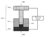
- FIG. 2 is a schematic view showing a method of evaluating the ion conductivity.
- FIG. 3 is a graph showing evaluation results of ion conductivity by AC impedance measurement.
- FIG. 4 is a graph showing initial discharge characteristics.
- the solid electrolyte material in the first embodiment is a solid electrolyte material represented by the following composition formula (1).
- M is one or more elements selected from the group consisting of Al, Sc, Ga, and Bi.
- a solid electrolyte material (halide solid electrolyte material) having high lithium ion conductivity can be realized.
- the solid electrolyte material of Embodiment 1 by using the solid electrolyte material of Embodiment 1, an all solid secondary battery excellent in charge and discharge characteristics can be realized. Further, by using the solid electrolyte material of Embodiment 1, it is possible to realize an all-solid secondary battery not containing sulfur. That is, the solid electrolyte material of Embodiment 1 is not a configuration that generates hydrogen sulfide when exposed to the air (for example, the configuration of Patent Document 1). Therefore, it is possible to realize an all-solid secondary battery excellent in safety without generating hydrogen sulfide.
- the solid electrolyte material in the first embodiment may satisfy 0.025 ⁇ a ⁇ 0.99 in the above composition formula (1).
- the solid electrolyte material in the first embodiment may satisfy 0.035 ⁇ a ⁇ 0.1 in the above composition formula (1).
- the solid electrolyte material in the first embodiment may satisfy ⁇ 0.5 ⁇ ⁇ ⁇ 0.5 in the above composition formula (1).
- the solid electrolyte material in the first embodiment may satisfy ⁇ 0.3 ⁇ ⁇ ⁇ 0.2 in the above composition formula (1).
- the solid electrolyte material in the first embodiment may be crystalline or amorphous.
- the shape of the solid electrolyte material in Embodiment 1 is not particularly limited, and may be, for example, needle-like, spherical, or elliptical spherical.
- the solid electrolyte material in Embodiment 1 may be particles. After laminating a plurality of particles, they may be formed into pellets or plates by pressure.
- the median diameter may be 0.1 ⁇ m or more and 100 ⁇ m or less.
- the median diameter may be 0.5 ⁇ m or more and 10 ⁇ m or less.
- the ion conductivity can be further enhanced.
- a better dispersed state of the solid electrolyte material, the active material, and the like in Embodiment 1 can be formed.
- the solid electrolyte material may be smaller than the median diameter of the active material.
- the solid electrolyte material in Embodiment 1 can be produced, for example, by the following method.
- LiCl, YCl 3 and BiCl 3 are prepared at a molar ratio of about 3: 0.95: 0.05.
- the blend ratio may be adjusted in advance to offset the change in consideration of the change in composition during the synthesis process.
- the above-mentioned values “ ⁇ ”, “a”, “x” and “y” can be adjusted by adjusting the raw materials, the compounding ratio and the synthesis process.
- the raw material powders are thoroughly mixed, the raw material powders are mixed, pulverized and reacted using a method of mechanochemical milling. Thereafter, it may be fired in vacuum or in an inert atmosphere.
- the raw material powders may be well mixed and then fired in vacuum or in an inert atmosphere.
- the firing conditions are preferably, for example, in the range of 100 ° C. to 650 ° C. for one hour or more.
- the battery in the second embodiment is configured using the solid electrolyte material described in the first embodiment described above.
- the battery in Embodiment 2 includes a solid electrolyte material, a positive electrode, a negative electrode, and an electrolyte layer.
- the electrolyte layer is a layer provided between the positive electrode and the negative electrode.
- At least one of the positive electrode, the electrolyte layer, and the negative electrode includes the solid electrolyte material according to the first embodiment.
- the charge and discharge characteristics of the battery can be improved.
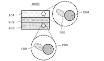
- FIG. 1 is a cross-sectional view showing a schematic configuration of a battery 1000 in the second embodiment.
- Battery 1000 in the second embodiment includes positive electrode 201, negative electrode 203, and electrolyte layer 202.
- the positive electrode 201 includes positive electrode active material particles 204 and solid electrolyte particles 100.
- the electrolyte layer 202 is disposed between the positive electrode 201 and the negative electrode 203.
- the electrolyte layer 202 includes an electrolyte material (eg, a solid electrolyte material).
- an electrolyte material eg, a solid electrolyte material
- the negative electrode 203 includes negative electrode active material particles 205 and solid electrolyte particles 100.
- Solid electrolyte particles 100 are particles made of the solid electrolyte material in the first embodiment, or particles containing the solid electrolyte material in the first embodiment as a main component.
- the positive electrode 201 includes a material having a property of absorbing and releasing metal ions (for example, lithium ions).
- the positive electrode 201 includes, for example, a positive electrode active material (for example, positive electrode active material particles 204).
- positive electrode active materials include lithium-containing transition metal oxides (eg, Li (NiCoAl) O 2 , LiCoO 2 , etc.), transition metal fluorides, polyanions and fluorinated polyanion materials, and transition metal sulfides, transitions Metal oxyfluorides, transition metal oxysulfides, transition metal oxynitrides, etc. may be used.
- the median diameter of the positive electrode active material particles 204 may be 0.1 ⁇ m or more and 100 ⁇ m or less. If the median diameter of the positive electrode active material particles 204 is smaller than 0.1 ⁇ m, there is a possibility that the positive electrode active material particles 204 and the halide solid electrolyte material can not form a good dispersed state at the positive electrode. As a result, the charge and discharge characteristics of the battery are degraded. In addition, when the median diameter of the positive electrode active material particles 204 is larger than 100 ⁇ m, lithium diffusion in the positive electrode active material particles 204 becomes slow. For this reason, the operation at high power of the battery may be difficult.
- the median diameter of the positive electrode active material particles 204 may be larger than the median diameter of the halide solid electrolyte material. Thereby, a good dispersed state of the positive electrode active material particles 204 and the halide solid electrolyte material can be formed.
- the volume ratio “v: 100 ⁇ v” of the positive electrode active material particles 204 and the halide solid electrolyte material contained in the positive electrode 201 may be 30 ⁇ v ⁇ 95.
- v ⁇ 30 it may be difficult to secure sufficient energy density of the battery.
- v> 95 operation at high output may be difficult.
- the thickness of the positive electrode 201 may be 10 ⁇ m or more and 500 ⁇ m or less. When the thickness of the positive electrode is smaller than 10 ⁇ m, it may be difficult to secure sufficient energy density of the battery. When the thickness of the positive electrode is greater than 500 ⁇ m, operation at high output may be difficult.
- the electrolyte layer 202 is a layer containing an electrolyte material.
- the electrolyte material is, for example, a solid electrolyte material. That is, the electrolyte layer 202 may be a solid electrolyte layer.
- the solid electrolyte layer may contain, as a main component, the solid electrolyte material described in the first embodiment. That is, the solid electrolyte layer may contain, for example, 50% or more (50% by weight or more) of the solid electrolyte material in the above-mentioned Embodiment 1 in a weight ratio to the entire solid electrolyte layer.
- the charge and discharge characteristics of the battery can be further improved.
- the solid electrolyte layer may contain, for example, 70% or more (70% by weight or more) of the solid electrolyte material in the above-described Embodiment 1 in a weight ratio to the entire solid electrolyte layer.
- the charge and discharge characteristics of the battery can be further improved.
- the solid electrolyte layer further includes unavoidable impurities or starting materials and by-products used when synthesizing the above-mentioned solid electrolyte material while containing the solid electrolyte material according to the above-mentioned Embodiment 1 as a main component. It may contain substances and decomposition products.
- the solid electrolyte layer may include, for example, 100% (100% by weight) of the solid electrolyte material in Embodiment 1 in terms of the weight ratio to the whole of the solid electrolyte layer except for impurities which are inevitably mixed.
- the charge and discharge characteristics of the battery can be further improved.
- the solid electrolyte layer may be composed of only the solid electrolyte material in the first embodiment.
- the solid electrolyte material different from the solid electrolyte material in the first embodiment may be used.
- a solid electrolyte material different from the solid electrolyte material in Embodiment 1 for example, Li 2 MgX 4 , Li 2 FeX 4 , Li (Al, Ga, In) X 4 , Li 3 (Al, Ga, In) X 6 , LiI, etc. (X: Cl, Br, I) may be used.
- the solid electrolyte layer may simultaneously contain the solid electrolyte material of Embodiment 1 and a solid electrolyte material different from the solid electrolyte material of Embodiment 1 described above. At this time, both may be dispersed uniformly.
- the layer made of the solid electrolyte material in Embodiment 1 and the layer made of a solid electrolyte material different from the solid electrolyte material in Embodiment 1 described above may be sequentially arranged in the stacking direction of the battery. .
- the thickness of the solid electrolyte layer may be 1 ⁇ m or more and 1000 ⁇ m or less.
- the thickness of the solid electrolyte layer is smaller than 1 ⁇ m, the possibility of short circuit between the positive electrode 201 and the negative electrode 203 is increased.
- the thickness of the solid electrolyte layer is thicker than 1000 ⁇ m, operation at high output may be difficult.
- the negative electrode 203 includes a material having a property of inserting and extracting metal ions (eg, lithium ions).
- the negative electrode 203 includes, for example, a negative electrode active material (for example, negative electrode active material particles 205).
- metal materials, carbon materials, oxides, nitrides, tin compounds, silicon compounds, etc. may be used.
- the metal material may be a single metal.
- the metal material may be an alloy.
- metal materials include lithium metal, lithium alloy, and the like.
- carbon materials include natural graphite, coke, graphitized carbon, carbon fibers, spherical carbon, artificial graphite, amorphous carbon and the like. From the viewpoint of capacity density, silicon (Si), tin (Sn), a silicon compound, and a tin compound can be suitably used.
- the negative electrode active material having a low average reaction voltage is used, the effect of suppressing the electrolysis by the solid electrolyte material in Embodiment 1 is exhibited better.
- the median diameter of the negative electrode active material particles 205 may be 0.1 ⁇ m or more and 100 ⁇ m or less. If the median diameter of the negative electrode active material particles 205 is smaller than 0.1 ⁇ m, there is a possibility that the negative electrode active material particles 205 and the solid electrolyte particles 100 can not form a good dispersed state in the negative electrode. This degrades the charge and discharge characteristics of the battery. In addition, when the median diameter of the negative electrode active material particles 205 is larger than 100 ⁇ m, the lithium diffusion in the negative electrode active material particles 205 becomes slow. For this reason, the operation at high power of the battery may be difficult.
- the median diameter of the negative electrode active material particles 205 may be larger than the median diameter of the solid electrolyte particles 100. Thereby, a favorable dispersed state of the negative electrode active material particles 205 and the halide solid electrolyte material can be formed.
- the volume ratio “v: 100 ⁇ v” of the negative electrode active material particles 205 to the solid electrolyte particles 100 contained in the negative electrode 203 may be 30 ⁇ v ⁇ 95.
- v ⁇ 30 it may be difficult to secure sufficient energy density of the battery.
- v> 95 operation at high output may be difficult.
- the thickness of the negative electrode 203 may be 10 ⁇ m or more and 500 ⁇ m or less. If the thickness of the negative electrode is smaller than 10 ⁇ m, it may be difficult to secure sufficient energy density of the battery. In addition, when the thickness of the negative electrode is greater than 500 ⁇ m, operation at high output may be difficult.
- At least one of the positive electrode 201, the electrolyte layer 202, and the negative electrode 203 contains a sulfide solid electrolyte or an oxide solid electrolyte for the purpose of enhancing ion conductivity or chemical stability / electrochemical stability.
- a sulfide solid electrolyte Li 2 S-P 2 S 5 , Li 2 S-SiS 2 , Li 2 S-B 2 S 3 , Li 2 S-GeS 2 , Li 3.25 Ge 0.25 P 0.75 S 4 , Li 10 GeP 2 S 12 , etc. may be used.
- a NASICON-type solid electrolyte represented by LiTi 2 (PO 4 ) 3 and its element substitution product, (LaLi) TiO 3 -based perovskite-type solid electrolyte, Li 14 ZnGe 4 O 16 , Li 4 SiO 4 LISICON type solid electrolyte represented by LiGeO 4 and its element substituted body, Garnet type solid electrolyte represented by Li 7 La 3 Zr 2 O 12 and its element substituted body, Li 3 N and its H substituted body, Li 3 PO 4 and its N-substituted, etc. can be used.
- An organic polymer solid electrolyte may be included in at least one of the positive electrode 201, the electrolyte layer 202, and the negative electrode 203 for the purpose of enhancing the ion conductivity.
- the organic polymer solid electrolyte for example, a compound of a polymer compound and a lithium salt can be used.
- the polymer compound may have an ethylene oxide structure. By having an ethylene oxide structure, a large amount of lithium salt can be contained, and the ionic conductivity can be further enhanced.
- the lithium salt LiPF 6, LiBF 4, LiSbF 6, LiAsF 6, LiSO 3 CF 3, LiN (SO 2 CF 3) 2, LiN (SO 2 C 2 F 5) 2, LiN (SO 2 CF 3) ( SO 2 C 4 F 9), LiC (SO 2 CF 3) 3, etc., may be used.
- a lithium salt one lithium salt selected therefrom can be used alone. Alternatively, a mixture of two or more lithium salts selected therefrom may be used as the lithium salt.
- At least one of the positive electrode 201, the electrolyte layer 202, and the negative electrode 203 contains a non-aqueous electrolyte solution, a gel electrolyte, and an ionic liquid in order to facilitate lithium ion transfer and improve the output characteristics of the battery. May be
- the non-aqueous electrolyte contains a non-aqueous solvent and a lithium salt dissolved in the non-aqueous solvent.
- a non-aqueous solvent cyclic carbonate solvents, chain carbonate solvents, cyclic ether solvents, chain ether solvents, cyclic ester solvents, chain ester solvents, fluorine solvents, and the like may be used.
- cyclic carbonate solvents include ethylene carbonate, propylene carbonate, butylene carbonate, and the like.
- chain carbonate solvents include dimethyl carbonate, ethyl methyl carbonate, diethyl carbonate, and the like.
- cyclic ether solvents examples include tetrahydrofuran, 1,4-dioxane, 1,3-dioxolane, and the like.
- the chain ether solvents include 1,2-dimethoxyethane, 1,2-diethoxyethane, and the like.
- cyclic ester solvents examples include ⁇ -butyrolactone and the like.
- linear ester solvents include methyl acetate and the like.
- fluorine solvents include fluoroethylene carbonate, methyl fluoropropionate, fluorobenzene, fluoroethyl methyl carbonate, fluorodimethylene carbonate, and the like.
- non-aqueous solvent one non-aqueous solvent selected therefrom can be used alone.
- the non-aqueous electrolytic solution may contain at least one fluorine solvent selected from the group consisting of fluoroethylene carbonate, methyl fluoropropionate, fluorobenzene, fluoroethyl methyl carbonate and fluorodimethylene carbonate.
- the lithium salt LiPF 6, LiBF 4, LiSbF 6, LiAsF 6, LiSO 3 CF 3, LiN (SO 2 CF 3) 2, LiN (SO 2 C 2 F 5) 2, LiN (SO 2 CF 3) ( SO 2 C 4 F 9), LiC (SO 2 CF 3) 3, etc., may be used.
- lithium salt one lithium salt selected therefrom can be used alone. Alternatively, a mixture of two or more lithium salts selected therefrom may be used as the lithium salt.
- concentration of the lithium salt is, for example, in the range of 0.5 to 2 mol / liter.
- the gel electrolyte one in which a non-aqueous electrolyte is contained in a polymer material can be used.
- a polymer material polyethylene oxide, polyacrylonitrile, polyvinylidene fluoride, polymethyl methacrylate, a polymer having an ethylene oxide bond, and the like may be used.
- the cations constituting the ionic liquid are aliphatic chain quaternary salts such as tetraalkylammonium and tetraalkylphosphonium, pyrrolidiniums, morpholiniums, imidazoliniums, tetrahydropyrimidiniums, piperaziniums, piperidiniums and the like And nitrogen-containing heterocyclic aromatic cations such as cyclic ammonium, pyridiniums, and imidazoliums.
- aliphatic chain quaternary salts such as tetraalkylammonium and tetraalkylphosphonium, pyrrolidiniums, morpholiniums, imidazoliniums, tetrahydropyrimidiniums, piperaziniums, piperidiniums and the like
- nitrogen-containing heterocyclic aromatic cations such as cyclic ammonium, pyridiniums, and imidazoliums.
- Anions constituting the ionic liquid are PF 6 ⁇ , BF 4 ⁇ , SbF 6 ⁇ ⁇ , AsF 6 ⁇ , SO 3 CF 3 ⁇ , N (SO 2 CF 3 ) 2 ⁇ , N (SO 2 C 2 F 5 ) 2 ⁇ , N (SO 2 CF 3 ) (SO 2 C 4 F 9 ) ⁇ , C (SO 2 CF 3 ) 3 ⁇ or the like.
- the ionic liquid may also contain a lithium salt.
- a binder may be contained in at least one of the positive electrode 201, the electrolyte layer 202, and the negative electrode 203 for the purpose of improving the adhesion between the particles.
- the binder is used to improve the binding properties of the material constituting the electrode.
- the binder polyvinylidene fluoride, polytetrafluoroethylene, polyethylene, polypropylene, aramid resin, polyamide, polyimide, polyamideimide, polyacrylonitrile, polyacrylic acid, polyacrylic acid methyl ester, polyacrylic acid ethyl ester, poly Acrylic acid hexyl ester, polymethacrylic acid, polymethacrylic acid methyl ester, polymethacrylic acid ethyl ester, polymethacrylic acid hexyl ester, polyvinyl acetate, polyvinyl pyrrolidone, polyether, polyether sulfone, hexafluoropolypropylene, styrene buta
- tetrafluoroethylene, hexafluoroethylene, hexafluoropropylene, perfluoroalkyl vinyl ether, vinylidene fluoride, chlorotrifluoroethylene, ethylene, propylene, pentafluoropropylene, fluoromethyl vinyl ether, acrylic acid, hexadiene Copolymers of two or more selected materials can be used. Moreover, 2 or more types selected from these may be mixed and it may be used as a binding agent.
- At least one of the positive electrode 201 and the negative electrode 203 may contain a conductive aid, if necessary.
- the conductive aid is used to reduce the electrode resistance.
- Conductive aids include graphites of natural graphite or artificial graphite, carbon blacks such as acetylene black and ketjen black, conductive fibers such as carbon fibers or metal fibers, metal powders such as fluorinated carbon and aluminum, Examples thereof include conductive whiskers such as zinc oxide or potassium titanate, conductive metal oxides such as titanium oxide, and conductive polymer compounds such as polyaniline, polypyrrole and polythiophene.
- cost reduction can be achieved by using a carbon conductive support as the conductive support.
- the battery in the second embodiment can be configured as a battery of various shapes such as coin type, cylindrical type, square type, sheet type, button type, flat type, and laminated type.
- Example 1 [Preparation of solid electrolyte material]
- FIG. 2 is a schematic view showing a method of evaluating the ion conductivity.
- the pressure forming die 300 is composed of an electrically insulating polycarbonate frame 301 and an electron conductive stainless steel punch upper portion 303 and a punch lower portion 302.
- the ion conductivity was evaluated by the following method using the configuration shown in FIG.
- the powder of the solid electrolyte material of Example 1 was filled in a pressure forming die 300 in a dry atmosphere with a dew point of ⁇ 30 ° C. or less, uniaxially pressurized at 400 MPa, and a conductivity measurement cell of Example 1 was produced.
- the ion conductivity was calculated from the following formula (2) using the resistance value of the electrolyte.
- ⁇ (R SE ⁇ S / t) ⁇ 1 ⁇ (2)
- ⁇ is the ion conductivity
- S is the electrolyte area (in FIG. 2, the inner diameter of the frame 301)
- R is the resistance value of the solid electrolyte in the above impedance measurement
- t is the thickness of the electrolyte (in FIG. Thickness of the compressed body of the solid electrolyte particle 100).
- the ion conductivity of the solid electrolyte material of Example 1 measured at 22 ° C. was 6.3 ⁇ 10 ⁇ 4 S / cm.
- the solid electrolyte material of Example 1 was laminated in the order of 700 ⁇ m thickness equivalent, 8.54 mg of the above-mentioned mixture, and 14.7 mg of Al powder.
- the first electrode and the solid electrolyte layer were obtained by pressure-molding this at a pressure of 300 MPa.
- metal In 200 micrometers in thickness
- pressure-molding this at a pressure of 80 MPa a laminate composed of the first electrode, the solid electrolyte layer, and the second electrode was produced.
- FIG. 4 is a graph showing initial discharge characteristics.
- Example 1 the secondary battery of Example 1 was disposed in a thermostat of 25 ° C.
- Constant current charging was performed at a current value at which a rate of 0.05 C (20-hour rate) with respect to the theoretical capacity of the battery was reached, and charging was terminated at a voltage of 3.6 V.
- the battery was discharged at a current value of 0.05 C rate, and the discharge was finished at a voltage of 2.0 V.
- the initial discharge capacity of the secondary battery of Example 1 was 888 ⁇ Ah.
- Example 21 raw material powders LiI, YBr 3 and MBr 3 were weighed so that the molar ratio of LiI: YBr 3 : MBr 3 would be 3: 0.95: 0.05.
- the weight was measured so as to be 0.05.
- the ion conductivity was measured in the same manner as in Example 1 except for the above.
- the secondary batteries of Examples 2 to 22 were produced in the same manner as in Example 1 except for the above.
- the ionic conductivity measured at 22 ° C. was 9 ⁇ 10 ⁇ 6 S / cm.
- the solid electrolyte material of Example 2 was used as a solid electrolyte used for the mixture and the solid electrolyte layer.
- the initial discharge capacity of the secondary battery of the example was 1 ⁇ Ah or less, and the charge / discharge operation could not be confirmed.
- Examples 1 to 22 exhibit high ion conductivity of 1 ⁇ 10 ⁇ 5 S / cm or more at around room temperature, as compared with Comparative Example 1.
- Examples 1 to 22 all showed the charge and discharge operation of the battery at room temperature. On the other hand, in Comparative Example 1, the discharge capacity was hardly obtained, and the battery operation could not be confirmed. Furthermore, since the materials of Examples 1 to 22 do not contain sulfur as a constituent element, there is no generation of hydrogen sulfide.
- the solid electrolyte material does not generate
- the battery of the present disclosure can be utilized, for example, as an all solid lithium secondary battery.
Abstract
固体電解質材料は、組成式Li3-3δY1+δ-aMaCl6-x-yBrxIyで表される。ここで、Mは、Al、Sc、Ga、及びBiからなる群より選択される少なくとも1種であり、-1<δ<1、 0<a<2、 0<(1+δ-a)、 0≦x≦6、 0≦y≦6、かつ、(x+y)≦6、を満たす。
Description
本開示は、固体電解質材料、および、電池に関する。
特許文献1には、硫化物固体電解質を用いた全固体電池が開示されている。
非特許文献1には、Li3YCl6が開示されている。
非特許文献2には、Li3YBr6が開示されている。
Z.Anorg.Allg.Chem.623(1997)、1067-1073.
Z.Anorg.Allg.Chem.623(1997)、1352-1356.
従来技術においては、高いリチウムイオン伝導度を有する固体電解質材料の実現が望まれる。
本開示の一様態における固体電解質材料は、組成式Li3-3δY1+δ-aMaCl6-x-yBrxIyで表される。ここで、Mは、Al、Sc、Ga、及びBiからなる群より選択される少なくとも1種であり、-1<δ<1、 0<a<2、 0<(1+δ-a)、 0≦x≦6、 0≦y≦6、かつ、(x+y)≦6、を満たす。
本開示によれば、高いリチウムイオン伝導度を有する固体電解質材料を実現できる。
以下、本開示の実施の形態が、図面を参照しながら説明される。
(実施の形態1)
実施の形態1における固体電解質材料は、下記の組成式(1)により表される固体電解質材料である。
Li3-3δY1+δ-aMaCl6-x-yBrxIy ・・・式(1)
ここで、Mは、Al、Sc、Ga、Biからなる群より選択される1種または2種以上の元素である。
実施の形態1における固体電解質材料は、下記の組成式(1)により表される固体電解質材料である。
Li3-3δY1+δ-aMaCl6-x-yBrxIy ・・・式(1)
ここで、Mは、Al、Sc、Ga、Biからなる群より選択される1種または2種以上の元素である。
さらに、
-1<δ<1、
0<a<2、
0<(1+δ-a)、
0≦x≦6、
0≦y≦6、
(x+y)≦6、
が満たされる。
-1<δ<1、
0<a<2、
0<(1+δ-a)、
0≦x≦6、
0≦y≦6、
(x+y)≦6、
が満たされる。
以上の構成によれば、高いリチウムイオン伝導度を有する固体電解質材料(ハロゲン化物固体電解質材料)を実現できる。
また、以上の構成によれば、実施の形態1の固体電解質材料を用いることで、充放電特性に優れた全固体二次電池を実現することができる。また、実施の形態1の固体電解質材料を用いることで、硫黄を含まない全固体二次電池を実現することができる。すなわち、実施の形態1の固体電解質材料は、大気に曝露された際に硫化水素が発生する構成(例えば、特許文献1の構成)ではない。このため、硫化水素の発生が無く、安全性に優れた全固体二次電池を実現することができる。
なお、実施の形態1における固体電解質材料は、上記の組成式(1)において、0.025≦a≦0.99、を満たしてもよい。
以上の構成によれば、より高いリチウムイオン伝導度を有する固体電解質材料を実現できる。
なお、実施の形態1における固体電解質材料は、上記の組成式(1)において、0.035≦a≦0.1、を満たしてもよい。
以上の構成によれば、より高いリチウムイオン伝導度を有する固体電解質材料を実現できる。
なお、実施の形態1における固体電解質材料は、上記の組成式(1)において、-0.5≦δ≦0.5、を満たしてもよい。
以上の構成によれば、より高いリチウムイオン伝導度を有する固体電解質材料を実現できる。
なお、実施の形態1における固体電解質材料は、上記の組成式(1)において、-0.3≦δ≦0.2、を満たしてもよい。
以上の構成によれば、より高いリチウムイオン伝導度を有する固体電解質材料を実現できる。
なお、実施の形態1における固体電解質材料は、結晶質であっても、非晶質であってもよい。
また、実施の形態1における固体電解質材料の形状は、特に限定されるものではなく、例えば、針状、球状、楕円球状など、であってもよい。例えば、実施の形態1における固体電解質材料は、粒子であってもよい。複数の粒子を積層した後、加圧によりペレット状もしくは板状に成形してもよい。
例えば、実施の形態1における固体電解質材料の形状が粒子状(例えば、球状)の場合、メジアン径は、0.1μm以上かつ100μm以下であってもよい。
また、実施の形態1においては、メジアン径は0.5μm以上かつ10μm以下であってもよい。
以上の構成によれば、イオン伝導性をより高めることができる。また、実施の形態1における固体電解質材料と活物質などとのより良好な分散状態を形成できる。
また、実施の形態1においては、固体電解質材料は、活物質のメジアン径より小さくてもよい。
以上の構成によれば、実施の形態1における固体電解質材料と活物質などとのより良好な分散状態を形成できる。
<固体電解質材料の製造方法>
実施の形態1における固体電解質材料は、例えば、下記の方法により、製造されうる。
実施の形態1における固体電解質材料は、例えば、下記の方法により、製造されうる。
目的とする組成の配合比となるような二元系ハロゲン化物の原料粉を用意する。例えば、Li3Y0.95Bi0.05Cl6を作製する場合には、LiClとYCl3とBiCl3を、3:0.95:0.05程度のモル比で用意する。合成プロセス過程における組成の変化を考慮して、変化分を相殺するようにあらかじめ配合比を調整してもよい。原料と配合比と合成プロセスを調整することで、上述の値「δ」、「a」、「x」、「y」を調整できる。
原料粉をよく混合した後、メカノケミカルミリングの方法を用いて原料粉同士を混合・粉砕・反応させる。その後、真空中または不活性雰囲気中で焼成してもよい。
もしくは、原料粉をよく混合した後、真空中または不活性雰囲気中で焼成してもよい。焼成条件は、例えば、100℃~650℃の範囲内で、1時間以上の焼成を行うことが好ましい。
これにより、前述したような組成を含む固体電解質材料が得られる。
(実施の形態2)
以下、実施の形態2が説明される。上述の実施の形態1と重複する説明は、適宜、省略される。
以下、実施の形態2が説明される。上述の実施の形態1と重複する説明は、適宜、省略される。
実施の形態2における電池は、上述の実施の形態1で説明された固体電解質材料を用いて構成される。
実施の形態2における電池は、固体電解質材料と、正極と、負極と、電解質層と、を備える。
電解質層は、正極と負極との間に設けられる層である。
正極と電解質層と負極とのうちの少なくとも1つは、実施の形態1における固体電解質材料を含む。
以上の構成によれば、電池の充放電特性を向上させることができる。
以下に、実施の形態2における電池の具体例が、説明される。
図1は、実施の形態2における電池1000の概略構成を示す断面図である。
実施の形態2における電池1000は、正極201と、負極203と、電解質層202とを備える。
正極201は、正極活物質粒子204と固体電解質粒子100とを含む。
電解質層202は、正極201と負極203との間に配置される。
電解質層202は、電解質材料(例えば、固体電解質材料)を含む。
負極203は、負極活物質粒子205と固体電解質粒子100とを含む。
固体電解質粒子100は、実施の形態1における固体電解質材料からなる粒子、または、実施の形態1における固体電解質材料を主たる成分として含む粒子である。
正極201は、金属イオン(例えば、リチウムイオン)を吸蔵・放出する特性を有する材料を含む。正極201は、例えば、正極活物質(例えば、正極活物質粒子204)を含む。
正極活物質には、例えば、リチウム含有遷移金属酸化物(例えば、Li(NiCoAl)O2、LiCoO2、など)、遷移金属フッ化物、ポリアニオンおよびフッ素化ポリアニオン材料、および、遷移金属硫化物、遷移金属オキシフッ化物、遷移金属オキシ硫化物、遷移金属オキシ窒化物、など、が用いられうる。
正極活物質粒子204のメジアン径は、0.1μm以上かつ100μm以下であってもよい。正極活物質粒子204のメジアン径が0.1μmより小さいと、正極において、正極活物質粒子204とハロゲン化物固体電解質材料とが、良好な分散状態を形成できない可能性が生じる。この結果、電池の充放電特性が低下する。また、正極活物質粒子204のメジアン径が100μmより大きいと、正極活物質粒子204内のリチウム拡散が遅くなる。このため、電池の高出力での動作が困難となる場合がある。
正極活物質粒子204のメジアン径は、ハロゲン化物固体電解質材料のメジアン径よりも、大きくてもよい。これにより、正極活物質粒子204とハロゲン化物固体電解質材料との良好な分散状態を形成できる。
正極201に含まれる、正極活物質粒子204とハロゲン化物固体電解質材料の体積比率「v:100-v」について、30≦v≦95であってもよい。v<30では、十分な電池のエネルギー密度確保が困難となる可能性がある。また、v>95では、高出力での動作が困難となる可能性がある。
正極201の厚みは、10μm以上かつ500μm以下であってもよい。なお、正極の厚みが10μmより薄い場合には、十分な電池のエネルギー密度の確保が困難となる可能性がある。なお、正極の厚みが500μmより厚い場合には、高出力での動作が困難となる可能性がある。
電解質層202は、電解質材料を含む層である。当該電解質材料は、例えば、固体電解質材料である。すなわち、電解質層202は、固体電解質層であってもよい。
なお、固体電解質層は、上述の実施の形態1における固体電解質材料を、主成分として、含んでもよい。すなわち、固体電解質層は、上述の実施の形態1における固体電解質材料を、例えば、固体電解質層の全体に対する重量割合で50%以上(50重量%以上)、含んでもよい。
以上の構成によれば、電池の充放電特性を、より向上させることができる。
また、固体電解質層は、上述の実施の形態1における固体電解質材料を、例えば、固体電解質層の全体に対する重量割合で70%以上(70重量%以上)、含んでもよい。
以上の構成によれば、電池の充放電特性を、より向上させることができる。
なお、固体電解質層は、上述の実施の形態1における固体電解質材料を主成分として含みながら、さらに、不可避的な不純物、または、上述の固体電解質材料を合成する際に用いられる出発原料および副生成物および分解生成物など、を含んでいてもよい。
また、固体電解質層は、実施の形態1における固体電解質材料を、例えば、混入が不可避的な不純物を除いて、固体電解質層の全体に対する重量割合で100%(100重量%)、含んでもよい。
以上の構成によれば、電池の充放電特性を、より向上させることができる。
以上のように、固体電解質層は、実施の形態1における固体電解質材料のみから構成されていてもよい。
もしくは、実施の形態1における固体電解質材料とは異なる固体電解質材料のみから構成されていてもよい。実施の形態1における固体電解質材料とは異なる固体電解質材料として、例えば、Li2MgX4、Li2FeX4、Li(Al,Ga,In)X4、Li3(Al,Ga,In)X6、LiI、など(X:Cl,Br,I)、が用いられうる。
固体電解質層は、実施の形態1における固体電解質材料と、上述の実施の形態1における固体電解質材料とは異なる固体電解質材料とを、同時に含んでもよい。このとき、両者が均一に分散していてもよい。実施の形態1における固体電解質材料からなる層と、上述の実施の形態1における固体電解質材料とは異なる固体電解質材料からなる層とが、電池の積層方向に対して、順に配置されていてもよい。
固体電解質層の厚みは、1μm以上かつ1000μm以下であってもよい。固体電解質層の厚みが1μmより薄い場合には、正極201と負極203とが短絡する可能性が高まる。また、固体電解質層の厚みが1000μmより厚い場合には、高出力での動作が困難となる可能性がある。
負極203は、金属イオン(例えば、リチウムイオン)を吸蔵・放出する特性を有する材料を含む。負極203は、例えば、負極活物質(例えば、負極活物質粒子205)を含む。
負極活物質には、金属材料、炭素材料、酸化物、窒化物、錫化合物、珪素化合物、など、が使用されうる。金属材料は、単体の金属であってもよい。もしくは、金属材料は、合金であってもよい。金属材料の例として、リチウム金属、リチウム合金、など、が挙げられる。炭素材料の例として、天然黒鉛、コークス、黒鉛化途上炭素、炭素繊維、球状炭素、人造黒鉛、非晶質炭素、など、が挙げられる。容量密度の観点から、珪素(Si)、錫(Sn)、珪素化合物、錫化合物、を好適に使用できる。平均反応電圧が低い負極活物質を用いた場合に、実施の形態1における固体電解質材料による電気分解抑制の効果が、より良く発揮される。
負極活物質粒子205のメジアン径は、0.1μm以上かつ100μm以下であってもよい。負極活物質粒子205のメジアン径が0.1μmより小さいと、負極において、負極活物質粒子205と固体電解質粒子100とが、良好な分散状態を形成できない可能性が生じる。これにより、電池の充放電特性が低下する。また、負極活物質粒子205のメジアン径が100μmより大きいと、負極活物質粒子205内のリチウム拡散が遅くなる。このため、電池の高出力での動作が困難となる場合がある。
負極活物質粒子205のメジアン径は、固体電解質粒子100のメジアン径よりも、大きくてもよい。これにより、負極活物質粒子205とハロゲン化物固体電解質材料との良好な分散状態を形成できる。
負極203に含まれる、負極活物質粒子205と固体電解質粒子100の体積比率「v:100-v」について、30≦v≦95であってもよい。v<30では、十分な電池のエネルギー密度確保が困難となる可能性がある。また、v>95では、高出力での動作が困難となる可能性がある。
負極203の厚みは、10μm以上かつ500μm以下であってもよい。負極の厚みが10μmより薄い場合には、十分な電池のエネルギー密度の確保が困難となる可能性がある。また、負極の厚みが500μmより厚い場合には、高出力での動作が困難となる可能性がある。
正極201と電解質層202と負極203とのうちの少なくとも1つには、イオン伝導性または化学的安定性・電気化学的安定性を高める目的で、硫化物固体電解質または酸化物固体電解質が含まれてもよい。硫化物固体電解質として、Li2S-P2S5、Li2S-SiS2、Li2S-B2S3、Li2S-GeS2、Li3.25Ge0.25P0.75S4、Li10GeP2S12、など、が用いられうる。酸化物固体電解質として、LiTi2(PO4)3およびその元素置換体を代表とするNASICON型固体電解質、(LaLi)TiO3系のペロブスカイト型固体電解質、Li14ZnGe4O16、Li4SiO4、LiGeO4およびその元素置換体を代表とするLISICON型固体電解質、Li7La3Zr2O12およびその元素置換体を代表とするガーネット型固体電解質、Li3NおよびそのH置換体、Li3PO4およびそのN置換体、など、が用いられうる。
正極201と電解質層202と負極203とのうちの少なくとも1つには、イオン伝導性を高める目的で、有機ポリマー固体電解質が含まれてもよい。有機ポリマー固体電解質として、例えば高分子化合物と、リチウム塩との化合物が用いられうる。高分子化合物はエチレンオキシド構造を有していてもよい。エチレンオキシド構造を有することで、リチウム塩を多く含有することができ、イオン導電率をより高めることができる。リチウム塩としては、LiPF6、LiBF4、LiSbF6、LiAsF6、LiSO3CF3、LiN(SO2CF3)2、LiN(SO2C2F5)2、LiN(SO2CF3)(SO2C4F9)、LiC(SO2CF3)3、など、が使用されうる。リチウム塩として、これらから選択される1種のリチウム塩が、単独で、使用されうる。もしくは、リチウム塩として、これらから選択される2種以上のリチウム塩の混合物が、使用されうる。
正極201と電解質層202と負極203とのうちの少なくとも1つには、リチウムイオンの授受を容易にし、電池の出力特性を向上する目的で、非水電解質液、ゲル電解質、イオン液体が含まれてもよい。
非水電解液は、非水溶媒と、非水溶媒に溶けたリチウム塩と、を含む。非水溶媒としては、環状炭酸エステル溶媒、鎖状炭酸エステル溶媒、環状エーテル溶媒、鎖状エーテル溶媒、環状エステル溶媒、鎖状エステル溶媒、フッ素溶媒、など、が使用されうる。環状炭酸エステル溶媒の例としては、エチレンカーボネート、プロピレンカーボネート、ブチレンカーボネート、など、が挙げられる。鎖状炭酸エステル溶媒の例としては、ジメチルカーボネート、エチルメチルカーボネート、ジエチルカーボネート、など、が挙げられる。環状エーテル溶媒の例としては、テトラヒドロフラン、1,4-ジオキサン、1,3-ジオキソラン、など、が挙げられる。鎖状エーテル溶媒としては、1,2-ジメトキシエタン、1,2-ジエトキシエタン、など、が挙げられる。環状エステル溶媒の例としては、γ-ブチロラクトン、など、が挙げられる。鎖状エステル溶媒の例としては、酢酸メチル、など、が挙げられる。フッ素溶媒の例としては、フルオロエチレンカーボネート、フルオロプロピオン酸メチル、フルオロベンゼン、フルオロエチルメチルカーボネート、フルオロジメチレンカーボネート、など、が挙げられる。非水溶媒として、これらから選択される1種の非水溶媒が、単独で、使用されうる。もしくは、非水溶媒として、これらから選択される2種以上の非水溶媒の組み合わせが、使用されうる。非水電解液には、フルオロエチレンカーボネート、フルオロプロピオン酸メチル、フルオロベンゼン、フルオロエチルメチルカーボネート、フルオロジメチレンカーボネートからなる群より選択される少なくとも1種のフッ素溶媒が含まれていてもよい。リチウム塩としては、LiPF6、LiBF4、LiSbF6、LiAsF6、LiSO3CF3、LiN(SO2CF3)2、LiN(SO2C2F5)2、LiN(SO2CF3)(SO2C4F9)、LiC(SO2CF3)3、など、が使用されうる。リチウム塩として、これらから選択される1種のリチウム塩が、単独で、使用されうる。もしくは、リチウム塩として、これらから選択される2種以上のリチウム塩の混合物が、使用されうる。リチウム塩の濃度は、例えば、0.5~2mol/リットルの範囲にある。
ゲル電解質は、ポリマー材料に非水電解液を含ませたものを用いることができる。ポリマー材料として、ポリエチレンオキシド、ポリアクリルニトリル、ポリフッ化ビニリデン、ポリメチルメタクリレート、エチレンオキシド結合を有するポリマー、など、が用いられてもよい。
イオン液体を構成するカチオンは、テトラアルキルアンモニウム、テトラアルキルホスホニウムなどの脂肪族鎖状4級塩類、ピロリジニウム類、モルホリニウム類、イミダゾリニウム類、テトラヒドロピリミジニウム類、ピペラジニウム類、ピペリジニウム類などの脂肪族環状アンモニウム、ピリジニウム類、イミダゾリウム類などの含窒ヘテロ環芳香族カチオンなどであってもよい。イオン液体を構成するアニオンは、PF6
-、BF4
-、SbF6-
-、AsF6
-、SO3CF3
-、N(SO2CF3)2
-、N(SO2C2F5)2
-、N(SO2CF3)(SO2C4F9)-、C(SO2CF3)3
-などであってもよい。また、イオン液体はリチウム塩を含有してもよい。
正極201と電解質層202と負極203とのうちの少なくとも1つには、粒子同士の密着性を向上する目的で、結着剤が含まれてもよい。結着剤は、電極を構成する材料の結着性を向上するために、用いられる。結着剤としては、ポリフッ化ビニリデン、ポリテトラフルオロエチレン、ポリエチレン、ポリプロピレン、アラミド樹脂、ポリアミド、ポリイミド、ポリアミドイミド、ポリアクリルニトリル、ポリアクリル酸、ポリアクリル酸メチルエステル、ポリアクリル酸エチルエステル、ポリアクリル酸ヘキシルエステル、ポリメタクリル酸、ポリメタクリル酸メチルエステル、ポリメタクリル酸エチルエステル、ポリメタクリル酸ヘキシルエステル、ポリ酢酸ビニル、ポリビニルピロリドン、ポリエーテル、ポリエーテルサルフォン、ヘキサフルオロポリプロピレン、スチレンブタジエンゴム、カルボキシメチルセルロース、など、が挙げられる。また、結着剤としては、テトラフルオロエチレン、ヘキサフルオロエチレン、ヘキサフルオロプロピレン、パーフルオロアルキルビニルエーテル、フッ化ビニリデン、クロロトリフルオロエチレン、エチレン、プロピレン、ペンタフルオロプロピレン、フルオロメチルビニルエーテル、アクリル酸、ヘキサジエンより選択された2種以上の材料の共重合体が用いられうる。また、これらのうちから選択された2種以上が混合されて、結着剤として用いられてもよい。
また、正極201および負極203のうちの少なくとも一方は、必要に応じて、導電助剤を含んでもよい。
導電助剤は、電極抵抗を低減するために、用いられる。導電助剤としては、天然黒鉛または人造黒鉛のグラファイト類、アセチレンブラック、ケッチェンブラックなどのカーボンブラック類、炭素繊維または金属繊維などの導電性繊維類、フッ化カーボン、アルミニウムなどの金属粉末類、酸化亜鉛またはチタン酸カリウムなどの導電性ウィスカー類、酸化チタンなどの導電性金属酸化物、ポリアニリン、ポリピロール、ポリチオフェンなどの導電性高分子化合物、など、が挙げられる。なお、導電助剤として、炭素導電助剤を用いることで、低コスト化が図れる。
なお、実施の形態2における電池は、コイン型、円筒型、角型、シート型、ボタン型、扁平型、積層型、など、種々の形状の電池として、構成されうる。
以下、実施例および比較例を用いて、本開示の詳細が説明される。
≪実施例1≫
[固体電解質材料の作製]
露点-60℃以下のアルゴン雰囲気で、原料粉LiClとYCl3とBiCl3とを、モル比でLiCl:YCl3:BiCl3=3:0.95:0.05となるように、秤量した。これらを乳鉢で粉砕して混合した。その後、遊星型ボールミルを用い、25時間、600rpmでミリング処理した。
[固体電解質材料の作製]
露点-60℃以下のアルゴン雰囲気で、原料粉LiClとYCl3とBiCl3とを、モル比でLiCl:YCl3:BiCl3=3:0.95:0.05となるように、秤量した。これらを乳鉢で粉砕して混合した。その後、遊星型ボールミルを用い、25時間、600rpmでミリング処理した。
以上により、Li3Y0.95Bi0.05Cl6の組成式で表される実施例1の固体電解質材料の粉末を得た。
[リチウムイオン伝導度の評価]
図2は、イオン伝導度の評価方法を示す模式図である。
図2は、イオン伝導度の評価方法を示す模式図である。
加圧成形用ダイス300は、電子的に絶縁性のポリカーボネート製の枠型301と、電子伝導性のステンレス製のパンチ上部303およびパンチ下部302とから構成される。
図2に示す構成を用いて、下記の方法にて、イオン伝導度の評価を行った。
露点-30℃以下のドライ雰囲気で、実施例1の固体電解質材料の粉末を加圧成形用ダイス300に充填し、400MPaで一軸加圧し、実施例1の伝導度測定セルを作製した。
加圧状態のまま、パンチ上部303とパンチ下部302のそれぞれから導線を取り回し、周波数応答アナライザを搭載したポテンショスタット(Princeton Applied Research社 VersaSTAT4)に接続し、電気化学的インピーダンス測定法により、室温におけるイオン伝導度の測定を行った。
インピーダンス測定結果のCole-Cole線図を図3に示す。
図3において、複素インピーダンスの位相の絶対値が最も小さい測定点(図3中の矢印)のインピーダンスの実数値を実施例1の固体電解質のイオン伝導に対する抵抗値とみなした。
電解質の抵抗値を用いて、下記式(2)より、イオン伝導度を算出した。
σ=(RSE×S/t)-1 ・・・・(2)
ここで、σはイオン伝導度、Sは電解質面積(図2中、枠型301の内径)、Rは上記のインピーダンス測定における固体電解質の抵抗値、tは電解質の厚み(図2中、複数の固体電解質粒子100の圧縮体の厚み)である。
σ=(RSE×S/t)-1 ・・・・(2)
ここで、σはイオン伝導度、Sは電解質面積(図2中、枠型301の内径)、Rは上記のインピーダンス測定における固体電解質の抵抗値、tは電解質の厚み(図2中、複数の固体電解質粒子100の圧縮体の厚み)である。
22℃で測定された、実施例1の固体電解質材料のイオン伝導度は、6.3×10⁻⁴S/cmであった。
[二次電池の作製]
アルゴングローブボックス内で、実施例1の固体電解質材料と、活物質であるLiCoO2(以下、LCOと表記する)を、70:30の体積比率で秤量した。これらをメノウ乳鉢で混合することで、合剤を作製した。
アルゴングローブボックス内で、実施例1の固体電解質材料と、活物質であるLiCoO2(以下、LCOと表記する)を、70:30の体積比率で秤量した。これらをメノウ乳鉢で混合することで、合剤を作製した。
絶縁性外筒の中で、実施例1の固体電解質材料を700μm厚相当分、上述の合剤を8.54mg、Al粉末を14.7mgの順に積層した。これを300MPaの圧力で加圧成型することで、第1電極と固体電解質層を得た。
次に、固体電解質層の第1電極と接する側とは反対側に、金属In(厚さ200μm)を積層した。これを80MPaの圧力で加圧成型することで、第1電極、固体電解質層、第2電極からなる積層体を作製した。
次に、積層体の上下にステンレス鋼集電体を配置し、集電体に集電リードを付設した。
最後に、絶縁性フェルールを用いて、絶縁性外筒内部を外気雰囲気から遮断・密閉した。
以上により、実施例1の二次電池を作製した。
[充放電試験]
図4は、初期放電特性を示すグラフである。
図4は、初期放電特性を示すグラフである。
図4に示される結果は、下記の方法により、測定された。
すなわち、実施例1の二次電池を、25℃の恒温槽に、配置した。
電池の理論容量に対して0.05Cレート(20時間率)となる電流値で、定電流充電し、電圧3.6Vで充電を終了した。
次に、同じく0.05Cレートとなる電流値で、放電し、電圧2.0Vで放電を終了した。
以上の測定の結果、実施例1の二次電池の初期放電容量は、888μAhであった。
≪実施例2~22≫
以下、Li3-3δY1+δ-aMaCl6-x-yBrxIyの合成および評価方法について説明する。
以下、Li3-3δY1+δ-aMaCl6-x-yBrxIyの合成および評価方法について説明する。
[固体電解質材料の作製]
実施例2~22においては、露点-90℃以下、酸素値5ppm以下のドライ・低酸素雰囲気で保たれるグローブボックス内で、原料粉を秤量した。
実施例2~22においては、露点-90℃以下、酸素値5ppm以下のドライ・低酸素雰囲気で保たれるグローブボックス内で、原料粉を秤量した。
実施例2~17においては、原料粉LiClとYCl3とMCl3とを、モル比でLiCl:YCl3:MCl3=(3-3δ):(1+δ―a):aとなるように、秤量した。
実施例18においては、原料粉LiBrとYBr3とMBr3とを、モル比でLiBr:YBr3:MBr3=(3-3δ):(1+δ―a):aとなるように、秤量した。
実施例19と20においては、原料粉LiClとYBr3とMBr3とを、モル比でLiCl:YBr3:MBr3=3:(1-a):aとなるように、秤量した。
実施例21においては、原料粉LiIとYBr3とMBr3とを、モル比でLiI:YBr3:MBr3=3:0.95:0.05となるように、秤量した。
実施例22においては、原料粉LiIとLiBrとYCl3とYBr3とMBr3とを、モル比でLiI:LiBr:YCl3:YBr3:MBr3=2:1:0.6667:0.2833:0.05となるように、秤量した。
実施例2~22のそれぞれにおける「δの値」、「aの値」、「Mの元素種」は、後述の表1に示される。
上記の実施例1と同様の方法で、実施例2~22のそれぞれの固体電解質材料を作製した。
[リチウムイオン伝導度の評価]
露点-90℃以下、酸素値5ppm以下のドライ・低酸素雰囲気で保たれるグローブボックス内で、上記の実施例1と同様の方法で、実施例2~22のそれぞれの伝導度測定セルを作製した。
露点-90℃以下、酸素値5ppm以下のドライ・低酸素雰囲気で保たれるグローブボックス内で、上記の実施例1と同様の方法で、実施例2~22のそれぞれの伝導度測定セルを作製した。
これ以外は、上記の実施例1と同様の方法で、イオン伝導度の測定を行った。
上述の実施例2~22におけるイオン伝導度は、後述の表1に示される。
[二次電池の作製]
露点-90℃以下、酸素値5ppm以下のドライ・低酸素雰囲気で保たれるグローブボックス内で、実施例2~22のそれぞれの固体電解質材料と、正極活物質であるLiCoO2を、30:70の体積比率で秤量した。これらをメノウ乳鉢で混合することで、実施例2~22のそれぞれの正極合剤を作製した。
露点-90℃以下、酸素値5ppm以下のドライ・低酸素雰囲気で保たれるグローブボックス内で、実施例2~22のそれぞれの固体電解質材料と、正極活物質であるLiCoO2を、30:70の体積比率で秤量した。これらをメノウ乳鉢で混合することで、実施例2~22のそれぞれの正極合剤を作製した。
これら以外は、上記の実施例1と同様の方法で、実施例2~22のそれぞれの二次電池を作製した。
[充放電試験]
上記の実施例1と同様の方法で、実施例2~22のそれぞれの二次電池の充放電試験を行った。
上記の実施例1と同様の方法で、実施例2~22のそれぞれの二次電池の充放電試験を行った。
実施例2~22の初期放電特性は、それぞれ、実施例1と同様の特性を示し、良好な充放電特性を得た。
≪比較例1≫
固体電解質の原料粉として、LiClとFeCl2とを用いて、LiCl:FeCl2=2:1のモル比で混合した。
固体電解質の原料粉として、LiClとFeCl2とを用いて、LiCl:FeCl2=2:1のモル比で混合した。
これ以外は、上記の実施例1と同様の方法で、それぞれの合成、評価および解析を、実施した。
22℃で測定されたイオン伝導度は、9×10⁻⁶S/cmであった。
また、合剤と固体電解質層に用いる固体電解質として、実施例2の固体電解質材料を用いた。
これ以外は、上記の実施例1と同様の方法で、二次電池の作製および充放電試験を、実施した。
実施例の二次電池の初期放電容量は、1μAh以下で、充放電動作は、確認できなかった。
上述の実施例1~22および比較例1における各構成と各評価結果とが、表1に示される。

≪考察≫
実施例1~22は、比較例1と比較して、室温近傍において、1×10⁻⁵S/cm以上の高いイオン伝導性を示すことがわかる。
実施例1~22は、比較例1と比較して、室温近傍において、1×10⁻⁵S/cm以上の高いイオン伝導性を示すことがわかる。
特に、式(1)で定義されるMの置換量aの値が0.01≦a≦0.99の範囲であれば、より高いイオン伝導性を示す。実施例1~3、8~17を比較すると、aの値がM=Biのときは0.01≦a≦0.5の範囲、M=Alのときは0.01≦a≦0.1の範囲、M=Scのときは0.01≦a≦0.99の範囲、M=Gaのときは0.01≦a≦0.1の範囲であれば、より高いイオン伝導性を示す。
又、化学量論比からのLi欠損量を示すδの値が-0.5≦δ≦0.5であれば、より高いイオン伝導性を示す。実施例4~7を比較すると、δの値が-0.3≦δ≦0.2の範囲であれば、より高いイオン伝導性を示す。
また、実施例1~22においては、いずれも室温において電池の充放電動作を示した。一方で、比較例1においては、放電容量がほとんど取れず、電池動作の確認ができなかった。さらに、実施例1~22の材料は、構成元素に硫黄を含まないため、硫化水素の発生がない。
以上により、本開示による固体電解質材料は、硫化水素の発生が無く、かつ、高いリチウムイオン伝導度を示し、良好な充放電動作をすることができる電解質材料であることが示される。
本開示の電池は、例えば、全固体リチウム二次電池などとして、利用されうる。
100 固体電解質粒子
201 正極
202 電解質層
203 負極
204 正極活物質粒子
205 負極活物質粒子
300 加圧成形用ダイス
301 枠型
302 パンチ下部
303 パンチ上部
1000 電池
201 正極
202 電解質層
203 負極
204 正極活物質粒子
205 負極活物質粒子
300 加圧成形用ダイス
301 枠型
302 パンチ下部
303 パンチ上部
1000 電池
Claims (6)
- 組成式Li3-3δY1+δ-aMaCl6-x-yBrxIyで表され、
ここで、Mは、Al、Sc、Ga、及びBiからなる群より選択される少なくとも1種であり、
-1<δ<1、
0<a<2、
0<(1+δ-a)、
0≦x≦6、
0≦y≦6、
(x+y)≦6、
を満たす、
固体電解質材料。 - 0.025≦a≦0.99、
を満たす、
請求項1に記載の固体電解質材料。 - 0.035≦a≦0.1、
を満たす、
請求項2に記載の固体電解質材料。 - -0.5≦δ≦0.5、
を満たす、
請求項1から3のいずれかに記載の固体電解質材料。 - -0.3≦δ≦0.2、
を満たす、
請求項4に記載の固体電解質材料。 - 請求項1から5のいずれかに記載の固体電解質材料と、
正極と、
負極と、
前記正極と前記負極との間に配置された電解質層と、
を備え、
前記正極と前記負極と前記電解質層とのうちの少なくとも1つは、前記固体電解質材料を含む、
電池。
Priority Applications (4)
| Application Number | Priority Date | Filing Date | Title |
|---|---|---|---|
| CN201880079441.1A CN111448619B (zh) | 2018-01-05 | 2018-11-13 | 固体电解质材料和电池 |
| EP18898663.2A EP3736829A4 (en) | 2018-01-05 | 2018-11-13 | SOLID ELECTROLYTE MATERIAL AND BATTERY |
| JP2019563935A JP7417925B2 (ja) | 2018-01-05 | 2018-11-13 | 固体電解質材料、および、電池 |
| US16/914,335 US11784345B2 (en) | 2018-01-05 | 2020-06-27 | Solid electrolyte material and battery |
Applications Claiming Priority (2)
| Application Number | Priority Date | Filing Date | Title |
|---|---|---|---|
| JP2018-000428 | 2018-01-05 | ||
| JP2018000428 | 2018-01-05 |
Related Child Applications (1)
| Application Number | Title | Priority Date | Filing Date |
|---|---|---|---|
| US16/914,335 Continuation US11784345B2 (en) | 2018-01-05 | 2020-06-27 | Solid electrolyte material and battery |
Publications (1)
| Publication Number | Publication Date |
|---|---|
| WO2019135320A1 true WO2019135320A1 (ja) | 2019-07-11 |
Family
ID=67143682
Family Applications (1)
| Application Number | Title | Priority Date | Filing Date |
|---|---|---|---|
| PCT/JP2018/041897 WO2019135320A1 (ja) | 2018-01-05 | 2018-11-13 | 固体電解質材料、および、電池 |
Country Status (5)
| Country | Link |
|---|---|
| US (1) | US11784345B2 (ja) |
| EP (1) | EP3736829A4 (ja) |
| JP (1) | JP7417925B2 (ja) |
| CN (1) | CN111448619B (ja) |
| WO (1) | WO2019135320A1 (ja) |
Cited By (11)
| Publication number | Priority date | Publication date | Assignee | Title |
|---|---|---|---|---|
| CN111509222A (zh) * | 2020-04-15 | 2020-08-07 | 国联汽车动力电池研究院有限责任公司 | 一种卤化物固态电解质材料及其制备方法和应用 |
| WO2021209380A1 (en) * | 2020-04-14 | 2021-10-21 | Solvay Sa | New lithium rare-earth halides |
| WO2021241172A1 (ja) | 2020-05-28 | 2021-12-02 | パナソニックIpマネジメント株式会社 | 固体電解質材料およびそれを用いた電池 |
| US11522217B2 (en) | 2020-04-14 | 2022-12-06 | Saint-Gobain Ceramics & Plastics, Inc. | Electrolyte material and methods of forming |
| US11532816B2 (en) | 2020-04-23 | 2022-12-20 | Saint-Gobain Ceramics & Plastics, Inc. | Ion conductive layer including binder material |
| US11637315B2 (en) | 2020-08-07 | 2023-04-25 | Saint-Gobain Ceramics & Plastics, Inc. | Electrolyte material and methods of forming |
| US11664531B2 (en) | 2020-04-14 | 2023-05-30 | Saint-Gobain Ceramics & Plastics, Inc. | Ion conductive material including complex metal halide, electrolyte including the same, and methods of forming the same |
| US11735765B2 (en) | 2021-01-08 | 2023-08-22 | Samsung Electronics Co., Ltd. | Solid ion conductor, solid electrolyte including the solid ion conductor, electrochemical device including the solid electrolyte, and method of preparing the solid ion conductor |
| US11757099B2 (en) | 2020-04-23 | 2023-09-12 | Saint-Gobain Ceramics & Plastics, Inc. | Ion conductive layer and methods of forming |
| US11848414B2 (en) | 2021-05-17 | 2023-12-19 | Saint-Gobain Ceramics & Plastics, Inc. | Electrolyte material and methods of forming |
| US11961962B2 (en) | 2020-07-02 | 2024-04-16 | Samsung Electronics Co., Ltd. | Solid ion conductor compound, solid electrolyte including the same, electrochemical cell including the same, and preparation method thereof |
Families Citing this family (16)
| Publication number | Priority date | Publication date | Assignee | Title |
|---|---|---|---|---|
| WO2019135348A1 (ja) | 2018-01-05 | 2019-07-11 | パナソニックIpマネジメント株式会社 | 固体電解質材料、および、電池 |
| CN111492524A (zh) | 2018-01-05 | 2020-08-04 | 松下知识产权经营株式会社 | 固体电解质材料和电池 |
| JP7228816B2 (ja) | 2018-01-05 | 2023-02-27 | パナソニックIpマネジメント株式会社 | 正極材料、および、電池 |
| CN111448619B (zh) | 2018-01-05 | 2021-11-05 | 松下知识产权经营株式会社 | 固体电解质材料和电池 |
| WO2019135343A1 (ja) | 2018-01-05 | 2019-07-11 | パナソニックIpマネジメント株式会社 | 固体電解質材料、および、電池 |
| CN111492443B (zh) | 2018-01-05 | 2022-04-29 | 松下知识产权经营株式会社 | 固体电解质材料和电池 |
| JP7253707B2 (ja) | 2018-01-05 | 2023-04-07 | パナソニックIpマネジメント株式会社 | 固体電解質材料、および、電池 |
| JP7182114B2 (ja) | 2018-01-05 | 2022-12-02 | パナソニックIpマネジメント株式会社 | 固体電解質材料、および、電池 |
| EP3736827A4 (en) | 2018-01-05 | 2021-03-10 | Panasonic Intellectual Property Management Co., Ltd. | SOLID ELECTROLYTE MATERIAL AND BATTERY |
| JP7281672B2 (ja) | 2018-01-05 | 2023-05-26 | パナソニックIpマネジメント株式会社 | 電池 |
| EP3745522A4 (en) | 2018-01-26 | 2021-03-17 | Panasonic Intellectual Property Management Co., Ltd. | DRUMS |
| WO2019146292A1 (ja) | 2018-01-26 | 2019-08-01 | パナソニックIpマネジメント株式会社 | 正極材料およびそれを用いた電池 |
| WO2019146296A1 (ja) | 2018-01-26 | 2019-08-01 | パナソニックIpマネジメント株式会社 | 正極材料およびそれを用いた電池 |
| JP7429870B2 (ja) | 2018-11-29 | 2024-02-09 | パナソニックIpマネジメント株式会社 | 負極材料、および電池 |
| CN112400242A (zh) | 2018-11-29 | 2021-02-23 | 松下知识产权经营株式会社 | 负极材料以及电池 |
| US11928472B2 (en) | 2020-09-26 | 2024-03-12 | Intel Corporation | Branch prefetch mechanisms for mitigating frontend branch resteers |
Citations (7)
| Publication number | Priority date | Publication date | Assignee | Title |
|---|---|---|---|---|
| JP2004235155A (ja) * | 2003-01-30 | 2004-08-19 | Samsung Electronics Co Ltd | 固体電解質、その製造方法及びそれを採用した電池 |
| JP2011129312A (ja) | 2009-12-16 | 2011-06-30 | Toyota Motor Corp | 硫化物固体電解質材料の製造方法、硫化物固体電解質材料およびリチウム電池 |
| CN105254184A (zh) * | 2015-11-27 | 2016-01-20 | 宁波大学 | 一种稀土离子掺杂的Li3YCl6微晶玻璃及其制备方法 |
| JP2016024874A (ja) * | 2014-07-16 | 2016-02-08 | 三井金属鉱業株式会社 | リチウムイオン電池用硫化物系固体電解質 |
| WO2017108105A1 (en) * | 2015-12-22 | 2017-06-29 | Toyota Motor Europe | Materials for solid electrolyte |
| WO2017154922A1 (ja) * | 2016-03-08 | 2017-09-14 | 株式会社村田製作所 | 固体電解質、全固体電池、固体電解質の製造方法及び全固体電池の製造方法 |
| WO2018025582A1 (ja) * | 2016-08-04 | 2018-02-08 | パナソニックIpマネジメント株式会社 | 固体電解質材料、および、電池 |
Family Cites Families (72)
| Publication number | Priority date | Publication date | Assignee | Title |
|---|---|---|---|---|
| JPS57132677A (en) | 1980-12-24 | 1982-08-17 | Union Carbide Corp | Solid electrolyte |
| US4352869A (en) | 1980-12-24 | 1982-10-05 | Union Carbide Corporation | Solid state electrolytes |
| US5714279A (en) | 1989-10-24 | 1998-02-03 | The United States Of America As Represented By The Secretary Of The Navy | Non-aqueous lithium cells |
| JP3151925B2 (ja) | 1992-05-07 | 2001-04-03 | 松下電器産業株式会社 | 非晶質リチウムイオン伝導性固体電解質並びにその合成法 |
| US5506073A (en) | 1992-06-22 | 1996-04-09 | Arizona State University (Arizona Board Of Regents, A Body Corporate Acting On Behalf Of Arizona State University) | Lithium ion conducting electrolytes |
| JPH08171938A (ja) | 1994-12-15 | 1996-07-02 | Mitsubishi Cable Ind Ltd | Li二次電池及びその正極 |
| JPH09293516A (ja) | 1996-04-25 | 1997-11-11 | Matsushita Electric Ind Co Ltd | 全固体リチウム電池 |
| JPH11238528A (ja) | 1998-02-20 | 1999-08-31 | Ngk Insulators Ltd | リチウム二次電池 |
| EP1049183B1 (en) | 1998-11-10 | 2011-08-03 | Panasonic Corporation | Lithium secondary cell |
| JP2001052733A (ja) | 1999-08-05 | 2001-02-23 | Matsushita Electric Ind Co Ltd | 全固体リチウム二次電池 |
| JP5076134B2 (ja) | 2004-06-08 | 2012-11-21 | 国立大学法人東京工業大学 | リチウム電池素子 |
| JP5108205B2 (ja) | 2005-02-28 | 2012-12-26 | 国立大学法人静岡大学 | 全固体型リチウム二次電池 |
| JP4945182B2 (ja) * | 2006-07-13 | 2012-06-06 | シャープ株式会社 | リチウム二次電池及びその製造方法 |
| JP2008060033A (ja) | 2006-09-04 | 2008-03-13 | Sony Corp | 正極活物質、これを用いた正極および非水電解質二次電池、並びに正極活物質の製造方法 |
| JP2008234988A (ja) | 2007-03-20 | 2008-10-02 | Sony Corp | 負極およびその製造方法、ならびに電池およびその製造方法 |
| JP5448038B2 (ja) | 2009-02-27 | 2014-03-19 | 公立大学法人大阪府立大学 | 硫化物固体電解質材料 |
| JP2011065982A (ja) | 2009-08-18 | 2011-03-31 | Seiko Epson Corp | リチウム電池用電極体及びリチウム電池 |
| JP5510084B2 (ja) | 2010-06-03 | 2014-06-04 | ソニー株式会社 | リチウムイオン二次電池用負極、リチウムイオン二次電池、電動工具、電気自動車および電力貯蔵システム |
| WO2012001773A1 (ja) | 2010-06-29 | 2012-01-05 | トヨタ自動車株式会社 | 硫化物固体電解質材料の製造方法、リチウム固体電池の製造方法 |
| JP5865268B2 (ja) | 2011-01-27 | 2016-02-17 | 出光興産株式会社 | アルカリ金属硫化物と導電剤の複合材料 |
| JP5721540B2 (ja) | 2011-05-30 | 2015-05-20 | 株式会社オハラ | リチウムイオン伝導性無機物質 |
| JP2013073791A (ja) | 2011-09-28 | 2013-04-22 | Panasonic Corp | 非水電解質二次電池 |
| JP5930035B2 (ja) | 2012-07-11 | 2016-06-08 | トヨタ自動車株式会社 | 全固体電池及びその製造方法 |
| FR3004467B1 (fr) | 2013-04-12 | 2016-05-27 | Saint-Gobain Cristaux Et Detecteurs | Fabrication d'une elpasolite stoechiometrique |
| FR3005207B1 (fr) | 2013-04-24 | 2016-06-24 | Batscap Sa | Electrode positive pour batterie lithium |
| JP6003831B2 (ja) | 2013-06-28 | 2016-10-05 | トヨタ自動車株式会社 | 硫化物固体電解質材料、硫化物ガラス、リチウム固体電池、および、硫化物固体電解質材料の製造方法 |
| WO2015011937A1 (ja) | 2013-07-25 | 2015-01-29 | 三井金属鉱業株式会社 | リチウムイオン電池用硫化物系固体電解質 |
| JP2015032529A (ja) | 2013-08-06 | 2015-02-16 | トヨタ自動車株式会社 | 硫化物系固体電解質 |
| JP6246816B2 (ja) | 2013-09-02 | 2017-12-13 | 三菱瓦斯化学株式会社 | 全固体電池 |
| JP6187069B2 (ja) | 2013-09-13 | 2017-08-30 | 富士通株式会社 | リチウム電池 |
| US10269465B2 (en) | 2013-10-04 | 2019-04-23 | National Institute Of Advanced Industrial Science And Technology | Amorphous (lithium) niobium sulfide or (lithium) titanium niobium sulfide |
| US9431753B2 (en) | 2013-12-30 | 2016-08-30 | Foxconn Interconnect Technology Limited | Connector with convenient installation |
| WO2015136623A1 (ja) | 2014-03-11 | 2015-09-17 | 富士通株式会社 | 複合固体電解質、及び全固体電池 |
| CN104953175A (zh) | 2014-03-28 | 2015-09-30 | 比亚迪股份有限公司 | 一种锂离子电池固体电解质及其制备方法和锂离子电池 |
| US9608288B2 (en) | 2014-07-17 | 2017-03-28 | Samsung Electronics Co., Ltd. | Positive electrode for lithium ion secondary battery and lithium ion secondary battery including the same |
| CN109065837B (zh) | 2014-11-10 | 2021-08-24 | 株式会社村田制作所 | 锂离子导体、电池及电子装置 |
| JP6222134B2 (ja) | 2015-02-25 | 2017-11-01 | トヨタ自動車株式会社 | 硫化物固体電解質材料、電池および硫化物固体電解質材料の製造方法 |
| JP6672848B2 (ja) | 2015-03-10 | 2020-03-25 | Tdk株式会社 | ガーネット型又はガーネット型類似の結晶構造を有するリチウムイオン伝導性酸化物セラミックス材料 |
| US10218032B2 (en) | 2015-03-10 | 2019-02-26 | Tdk Corporation | Li-ion conductive oxide ceramic material including garnet-type or similar crystal structure |
| US10446872B2 (en) | 2015-08-04 | 2019-10-15 | Samsung Electronics Co., Ltd. | Solid electrolyte and lithium battery including the same |
| JP2017059342A (ja) | 2015-09-15 | 2017-03-23 | トヨタ自動車株式会社 | 全固体電池の製造方法 |
| CN107431242B (zh) | 2015-09-16 | 2021-03-23 | 松下知识产权经营株式会社 | 电池 |
| JP2017091955A (ja) | 2015-11-16 | 2017-05-25 | 旭化成株式会社 | リチウムイオン伝導体及びこれを用いたリチウムイオン電池 |
| JP2017091953A (ja) | 2015-11-16 | 2017-05-25 | 旭化成株式会社 | リチウムイオン伝導体及びこれを用いたリチウムイオン電池 |
| JP2017111954A (ja) | 2015-12-16 | 2017-06-22 | セイコーエプソン株式会社 | 金属酸化物成膜用組成物、正極複合体、正極複合体の製造方法、電池、および電池の製造方法 |
| JP6881892B2 (ja) | 2015-12-25 | 2021-06-02 | 三星電子株式会社Samsung Electronics Co.,Ltd. | 固体電解質、全固体電池及び固体電解質の製造方法 |
| US11245131B2 (en) | 2015-12-25 | 2022-02-08 | Samsung Electronics Co., Ltd. | Solid electrolyte and lithium battery including the same |
| JP6748344B2 (ja) | 2016-02-26 | 2020-09-02 | 富士通株式会社 | 全固体電池 |
| JP6658127B2 (ja) | 2016-03-10 | 2020-03-04 | セイコーエプソン株式会社 | 固体電解質、固体電解質の製造方法およびリチウムイオン電池 |
| CN109219900B (zh) | 2016-04-05 | 2021-09-21 | 麻省理工学院 | 锂金属电极及其电池 |
| CN105680048B (zh) * | 2016-04-05 | 2019-05-17 | 惠州亿纬锂能股份有限公司 | 一种包含氮掺杂石墨烯的正极、其制备方法及采用该正极的锂电池 |
| CN107305965B (zh) | 2016-04-25 | 2022-03-29 | 松下知识产权经营株式会社 | 电池和电池制造方法 |
| JP2017224474A (ja) | 2016-06-15 | 2017-12-21 | 出光興産株式会社 | 正極合材 |
| CN108258358B (zh) | 2016-12-28 | 2022-11-11 | 松下知识产权经营株式会社 | 电池 |
| CN107425218B (zh) * | 2017-08-04 | 2019-10-15 | 郑州新世纪材料基因组工程研究院有限公司 | 一种锂离子固体电解质及其制备方法、应用 |
| CN111492524A (zh) | 2018-01-05 | 2020-08-04 | 松下知识产权经营株式会社 | 固体电解质材料和电池 |
| JP7253707B2 (ja) | 2018-01-05 | 2023-04-07 | パナソニックIpマネジメント株式会社 | 固体電解質材料、および、電池 |
| CN111448619B (zh) | 2018-01-05 | 2021-11-05 | 松下知识产权经营株式会社 | 固体电解质材料和电池 |
| JP7228816B2 (ja) | 2018-01-05 | 2023-02-27 | パナソニックIpマネジメント株式会社 | 正極材料、および、電池 |
| JP7182114B2 (ja) | 2018-01-05 | 2022-12-02 | パナソニックIpマネジメント株式会社 | 固体電解質材料、および、電池 |
| WO2019135321A1 (ja) | 2018-01-05 | 2019-07-11 | パナソニックIpマネジメント株式会社 | 固体電解質材料、および、電池 |
| WO2019135348A1 (ja) | 2018-01-05 | 2019-07-11 | パナソニックIpマネジメント株式会社 | 固体電解質材料、および、電池 |
| WO2019135343A1 (ja) | 2018-01-05 | 2019-07-11 | パナソニックIpマネジメント株式会社 | 固体電解質材料、および、電池 |
| EP3736825A4 (en) | 2018-01-05 | 2021-03-10 | Panasonic Intellectual Property Management Co., Ltd. | SOLID ELECTROLYTE AND BATTERY |
| JP7417927B2 (ja) | 2018-01-05 | 2024-01-19 | パナソニックIpマネジメント株式会社 | 固体電解質材料、および、電池 |
| EP3736827A4 (en) | 2018-01-05 | 2021-03-10 | Panasonic Intellectual Property Management Co., Ltd. | SOLID ELECTROLYTE MATERIAL AND BATTERY |
| JP7281672B2 (ja) | 2018-01-05 | 2023-05-26 | パナソニックIpマネジメント株式会社 | 電池 |
| CN111492443B (zh) | 2018-01-05 | 2022-04-29 | 松下知识产权经营株式会社 | 固体电解质材料和电池 |
| WO2019146294A1 (ja) | 2018-01-26 | 2019-08-01 | パナソニックIpマネジメント株式会社 | 電池 |
| JPWO2019146219A1 (ja) | 2018-01-26 | 2021-01-28 | パナソニックIpマネジメント株式会社 | 固体電解質材料、および、電池 |
| JPWO2019146218A1 (ja) | 2018-01-26 | 2021-01-28 | パナソニックIpマネジメント株式会社 | 固体電解質材料、および、電池 |
| EP3863028A4 (en) | 2018-10-01 | 2021-12-08 | Panasonic Intellectual Property Management Co., Ltd. | HALID SOLID ELECTROLYTE MATERIAL AND BATTERY WITH IT |
-
2018
- 2018-11-13 CN CN201880079441.1A patent/CN111448619B/zh active Active
- 2018-11-13 JP JP2019563935A patent/JP7417925B2/ja active Active
- 2018-11-13 EP EP18898663.2A patent/EP3736829A4/en active Pending
- 2018-11-13 WO PCT/JP2018/041897 patent/WO2019135320A1/ja unknown
-
2020
- 2020-06-27 US US16/914,335 patent/US11784345B2/en active Active
Patent Citations (7)
| Publication number | Priority date | Publication date | Assignee | Title |
|---|---|---|---|---|
| JP2004235155A (ja) * | 2003-01-30 | 2004-08-19 | Samsung Electronics Co Ltd | 固体電解質、その製造方法及びそれを採用した電池 |
| JP2011129312A (ja) | 2009-12-16 | 2011-06-30 | Toyota Motor Corp | 硫化物固体電解質材料の製造方法、硫化物固体電解質材料およびリチウム電池 |
| JP2016024874A (ja) * | 2014-07-16 | 2016-02-08 | 三井金属鉱業株式会社 | リチウムイオン電池用硫化物系固体電解質 |
| CN105254184A (zh) * | 2015-11-27 | 2016-01-20 | 宁波大学 | 一种稀土离子掺杂的Li3YCl6微晶玻璃及其制备方法 |
| WO2017108105A1 (en) * | 2015-12-22 | 2017-06-29 | Toyota Motor Europe | Materials for solid electrolyte |
| WO2017154922A1 (ja) * | 2016-03-08 | 2017-09-14 | 株式会社村田製作所 | 固体電解質、全固体電池、固体電解質の製造方法及び全固体電池の製造方法 |
| WO2018025582A1 (ja) * | 2016-08-04 | 2018-02-08 | パナソニックIpマネジメント株式会社 | 固体電解質材料、および、電池 |
Non-Patent Citations (4)
| Title |
|---|
| BOHNSACK, A. ET AL.: "Ternary halides of the A3 MX 6 type. VI. Ternary chlorides of the rare-earth elements with lithium, Li3MCl6 (M=Tb-Lu, Y, Sc): Synthesis, crystal structures, and ionic motion", ZEITSCHRIFT FÜR ANORGANISCHE UND ALLGEMEINE CHEMIE, vol. 623, 1997, pages 1067 - 1073, XP055600040, DOI: doi:10.1002/chin.199739018 * |
| BOHNSACK, A. ET AL.: "Ternary halides of the A3 MX 6 type. VII. The bromides Li3MBr6 (M=Sm-Lu, Y) : Synthesis, crystal structure, and ionic mobility", ZEITSCHRIFT FUR ANORGANISCHE UND ALLGEMEINE CHEMIE, vol. 623, 1997, pages 1352 - 1356, XP055600030, DOI: doi:10.1002/zaac.19976230905 * |
| See also references of EP3736829A4 |
| Z.ANORG.ALLG.CHEM., vol. 623, 1997, pages 1352 - 1356 |
Cited By (12)
| Publication number | Priority date | Publication date | Assignee | Title |
|---|---|---|---|---|
| WO2021209380A1 (en) * | 2020-04-14 | 2021-10-21 | Solvay Sa | New lithium rare-earth halides |
| US11522217B2 (en) | 2020-04-14 | 2022-12-06 | Saint-Gobain Ceramics & Plastics, Inc. | Electrolyte material and methods of forming |
| US11664531B2 (en) | 2020-04-14 | 2023-05-30 | Saint-Gobain Ceramics & Plastics, Inc. | Ion conductive material including complex metal halide, electrolyte including the same, and methods of forming the same |
| CN111509222A (zh) * | 2020-04-15 | 2020-08-07 | 国联汽车动力电池研究院有限责任公司 | 一种卤化物固态电解质材料及其制备方法和应用 |
| US11532816B2 (en) | 2020-04-23 | 2022-12-20 | Saint-Gobain Ceramics & Plastics, Inc. | Ion conductive layer including binder material |
| US11735732B2 (en) | 2020-04-23 | 2023-08-22 | Saint-Gobain Ceramics & Plastics, Inc. | Ion conductive layer and methods of forming |
| US11757099B2 (en) | 2020-04-23 | 2023-09-12 | Saint-Gobain Ceramics & Plastics, Inc. | Ion conductive layer and methods of forming |
| WO2021241172A1 (ja) | 2020-05-28 | 2021-12-02 | パナソニックIpマネジメント株式会社 | 固体電解質材料およびそれを用いた電池 |
| US11961962B2 (en) | 2020-07-02 | 2024-04-16 | Samsung Electronics Co., Ltd. | Solid ion conductor compound, solid electrolyte including the same, electrochemical cell including the same, and preparation method thereof |
| US11637315B2 (en) | 2020-08-07 | 2023-04-25 | Saint-Gobain Ceramics & Plastics, Inc. | Electrolyte material and methods of forming |
| US11735765B2 (en) | 2021-01-08 | 2023-08-22 | Samsung Electronics Co., Ltd. | Solid ion conductor, solid electrolyte including the solid ion conductor, electrochemical device including the solid electrolyte, and method of preparing the solid ion conductor |
| US11848414B2 (en) | 2021-05-17 | 2023-12-19 | Saint-Gobain Ceramics & Plastics, Inc. | Electrolyte material and methods of forming |
Also Published As
| Publication number | Publication date |
|---|---|
| US20200328468A1 (en) | 2020-10-15 |
| CN111448619B (zh) | 2021-11-05 |
| JPWO2019135320A1 (ja) | 2021-01-07 |
| EP3736829A1 (en) | 2020-11-11 |
| JP7417925B2 (ja) | 2024-01-19 |
| US11784345B2 (en) | 2023-10-10 |
| EP3736829A4 (en) | 2021-03-10 |
| CN111448619A (zh) | 2020-07-24 |
Similar Documents
| Publication | Publication Date | Title |
|---|---|---|
| JP7417927B2 (ja) | 固体電解質材料、および、電池 | |
| JP7417925B2 (ja) | 固体電解質材料、および、電池 | |
| JP7316571B2 (ja) | 固体電解質材料、および、電池 | |
| WO2019146219A1 (ja) | 固体電解質材料、および、電池 | |
| WO2019135343A1 (ja) | 固体電解質材料、および、電池 | |
| WO2019135315A1 (ja) | 固体電解質材料、および、電池 | |
| WO2019135345A1 (ja) | 固体電解質材料、および、電池 | |
| JP7417926B2 (ja) | 固体電解質材料、および、電池 | |
| WO2019146218A1 (ja) | 固体電解質材料、および、電池 | |
| WO2019135319A1 (ja) | 固体電解質材料、および、電池 | |
| WO2019146217A1 (ja) | 電池 | |
| JPWO2018025582A1 (ja) | 固体電解質材料、および、電池 | |
| WO2021070595A1 (ja) | 固体電解質材料およびそれを用いた電池 | |
| WO2019135341A1 (ja) | 固体電解質材料、および、電池 | |
| WO2019135342A1 (ja) | 固体電解質材料、および、電池 | |
| WO2021186809A1 (ja) | 固体電解質材料およびそれを用いた電池 | |
| WO2021186833A1 (ja) | 固体電解質材料およびそれを用いた電池 | |
| JP7417951B2 (ja) | リチウムイオン伝導性固体電解質材料、およびこれを用いた電池 | |
| WO2023013232A1 (ja) | 固体電解質材料およびそれを用いた電池 | |
| JP7329776B2 (ja) | 固体電解質材料、およびこれを用いた電池 | |
| WO2023074143A1 (ja) | 固体電解質材料および電池 | |
| WO2023162758A1 (ja) | 固体電解質材料 | |
| WO2022259749A1 (ja) | 固体電解質材料および電池 | |
| WO2022264659A1 (ja) | 固体電解質材料および電池 | |
| WO2023042560A1 (ja) | 固体電解質材料およびそれを用いた電池 |
Legal Events
| Date | Code | Title | Description |
|---|---|---|---|
| 121 | Ep: the epo has been informed by wipo that ep was designated in this application |
Ref document number: 18898663 Country of ref document: EP Kind code of ref document: A1 |
|
| ENP | Entry into the national phase |
Ref document number: 2019563935 Country of ref document: JP Kind code of ref document: A |
|
| NENP | Non-entry into the national phase |
Ref country code: DE |
|
| ENP | Entry into the national phase |
Ref document number: 2018898663 Country of ref document: EP Effective date: 20200805 |