WO2014199588A1 - 車両用空調装置 - Google Patents
車両用空調装置 Download PDFInfo
- Publication number
- WO2014199588A1 WO2014199588A1 PCT/JP2014/002918 JP2014002918W WO2014199588A1 WO 2014199588 A1 WO2014199588 A1 WO 2014199588A1 JP 2014002918 W JP2014002918 W JP 2014002918W WO 2014199588 A1 WO2014199588 A1 WO 2014199588A1
- Authority
- WO
- WIPO (PCT)
- Prior art keywords
- air
- heat exchanger
- guide
- heating
- heating heat
- Prior art date
- Legal status (The legal status is an assumption and is not a legal conclusion. Google has not performed a legal analysis and makes no representation as to the accuracy of the status listed.)
- Ceased
Links
Images



Classifications
-
- B—PERFORMING OPERATIONS; TRANSPORTING
- B60—VEHICLES IN GENERAL
- B60H—ARRANGEMENTS OF HEATING, COOLING, VENTILATING OR OTHER AIR-TREATING DEVICES SPECIALLY ADAPTED FOR PASSENGER OR GOODS SPACES OF VEHICLES
- B60H1/00—Heating, cooling or ventilating devices
- B60H1/00007—Combined heating, ventilating, or cooling devices
- B60H1/00021—Air flow details of HVAC devices
- B60H1/00035—Air flow details of HVAC devices for sending an air stream of uniform temperature into the passenger compartment
-
- B—PERFORMING OPERATIONS; TRANSPORTING
- B60—VEHICLES IN GENERAL
- B60H—ARRANGEMENTS OF HEATING, COOLING, VENTILATING OR OTHER AIR-TREATING DEVICES SPECIALLY ADAPTED FOR PASSENGER OR GOODS SPACES OF VEHICLES
- B60H1/00—Heating, cooling or ventilating devices
- B60H1/00007—Combined heating, ventilating, or cooling devices
- B60H1/00021—Air flow details of HVAC devices
- B60H1/00064—Air flow details of HVAC devices for sending air streams of different temperatures into the passenger compartment
-
- B—PERFORMING OPERATIONS; TRANSPORTING
- B60—VEHICLES IN GENERAL
- B60H—ARRANGEMENTS OF HEATING, COOLING, VENTILATING OR OTHER AIR-TREATING DEVICES SPECIALLY ADAPTED FOR PASSENGER OR GOODS SPACES OF VEHICLES
- B60H1/00—Heating, cooling or ventilating devices
- B60H1/00507—Details, e.g. mounting arrangements, desaeration devices
- B60H1/00557—Details of ducts or cables
- B60H1/00564—Details of ducts or cables of air ducts
-
- B—PERFORMING OPERATIONS; TRANSPORTING
- B60—VEHICLES IN GENERAL
- B60H—ARRANGEMENTS OF HEATING, COOLING, VENTILATING OR OTHER AIR-TREATING DEVICES SPECIALLY ADAPTED FOR PASSENGER OR GOODS SPACES OF VEHICLES
- B60H1/00—Heating, cooling or ventilating devices
- B60H1/00007—Combined heating, ventilating, or cooling devices
- B60H1/00021—Air flow details of HVAC devices
- B60H2001/00078—Assembling, manufacturing or layout details
- B60H2001/00092—Assembling, manufacturing or layout details of air deflecting or air directing means inside the device
Definitions
- This disclosure relates to a vehicle air conditioner including a heating heat exchanger for heating cold air from an evaporator in an air conditioning case.
- the present invention relates to a vehicle air conditioner that suppresses heating of the cold air by the downstream side wall surface of the unintended heating heat exchanger when the cold air flows above the heating heat exchanger and bypasses the heating heat exchanger.
- Patent Document 1 Conventionally, there is a vehicle air conditioner described in Patent Document 1.
- the cold air emitted from the evaporator is controlled by the first air mix door and the second air mix door, which are slide doors, and flows to the heating heat exchanger side.
- the cold air coming out of each air mix door is air that passes through the inside of the heat exchanger for heating, air that bypasses the heat exchanger for heating and passes through the top of the heat exchanger for heating (vehicle ceiling direction), and heating Divided into air passing through the heat exchanger lower part (vehicle floor direction). Then, these airs are blown into the vehicle interior from a differential outlet toward the windshield, a face outlet toward the occupant's face, and a foot outlet toward the occupant's feet.
- the air passing through the upper part of the heat exchanger for heating (in the vehicle ceiling direction) wraps around the downstream side of the heat exchanger for heating and is heated on the downstream side wall surface of the heat exchanger for heating. May end up.
- the temperature of the conditioned air blown into the vehicle compartment may vary.
- the cold air passage for bypass is divided into an upward direction and a downward direction centering on the heat exchanger. Therefore, at the time of so-called FACE mode MaxCool that cools the vehicle interior to the maximum from the face outlet, the air passing by bypassing the upper part of the heating heat exchanger (vehicle ceiling direction) is downstream of the heating heat exchanger. There may be a large flow into the space on the surface side. As a result, the air that has largely flowed into the space on the downstream surface side of the heating heat exchanger easily exchanges heat with the downstream side wall surface of the heating heat exchanger.
- An object of the present disclosure is to provide a vehicle air conditioner that can suppress the air flowing out of the cooling heat exchanger from flowing into the downstream side wall surface of the heating heat exchanger.
- a vehicle air conditioner includes a cooling heat exchanger that cools the inside air that is air in the vehicle interior and the outside air that is air outside the vehicle interior, and the downstream side in the air flow direction of the cooling heat exchanger.
- the heating heat exchanger for heating the cold air by controlling the flow of the cold air that is disposed between the heat exchanger for heating, the heat exchanger for cooling and the heat exchanger for cooling, and passed through the heat exchanger for cooling.
- An air mix door that adjusts the degree of heating by the exchanger, an outlet from which air adjusted in temperature by the air mix door blows out into the passenger compartment, and a heating heat exchanger that is arranged downstream of the air flow direction of the heat exchanger
- the air flow regulating wall that guides the air from the heat exchanger to the air outlet and the cold air from the cooling heat exchanger pass through the inside of the heating heat exchanger by controlling the air flow of the air mix door.
- First path to the outlet and heat exchanger for cooling Cold air exiting al comprises a second path to outlet from above the heating heat exchanger without passing through the inside of the heating heat exchanger by controlling the air flow of the air mix door, a.
- the air flow regulating wall has a plurality of guide plates that guide the air flow on the downstream side of the heating heat exchanger.
- the guide plate extends from the downstream side wall surface of the heat exchanger for heating to the downstream side in the air flow direction, is curved and extends upward, and air is supplied from the downstream side of the heating heat exchanger to the upward direction in the first path.
- a first guide that flows into the air outlet and leads to the outlet, a second guide that extends from the upper end of the heat exchanger for heating to the downstream side in the air flow direction, and that curves and extends downward, and from the first guide
- a third guide extending toward the tip of the second guide.
- the distance between the front end of the first guide and the downstream side wall surface of the heating heat exchanger is longer than the distance between the front end of the second guide and the downstream side wall surface of the heating heat exchanger.
- the cool air from the cooling heat exchanger is controlled in the air flow by the air mix door and passes through the inside of the heating heat exchanger.
- the air heated by the heating heat exchanger flows upward from the downstream side of the heating heat exchanger and reaches the outlet.
- the cool air from the cooling heat exchanger is controlled by the air mix door so that the air flow is not passed through the inside of the heating heat exchanger (that is, bypassing the heating heat exchanger) From the top of the heat exchanger for heating to the outlet.
- a guide plate that affects the wind flow downstream of the heat exchanger for heating is provided.
- the guide plate has a first guide that extends downstream from the downstream side wall surface of the heat exchanger for heating and is bent upward in order to form a first path. Therefore, the heated air that has exited the heating heat exchanger is guided to the first path.
- the guide plate has a second guide that extends downstream from the upper end of the heating heat exchanger and is bent upward in order to hold other heat exchangers. Further, the tip of the first guide is provided farther from the heating heat exchanger than the tip of the second guide.
- this contact heating air In order to suppress this contact heating air, it has a third guide extending from the first guide toward the tip of the second guide. Thereby, generation
- the dimension from the tip of the third guide to the tip of the second guide is set as dimension A.
- the dimension from the front end of the first guide to the front end of the second guide is defined as dimension B.
- the dimension A may be set in a range of 0.7 to 1.3 times the length of the dimension B.
- the dimension A is set in the range of 0.7 times to 1.3 times the length of the dimension B, the first path and the second path are controlled while suppressing the generation of contact heating air. Can be formed.
- the size relationship between the dimension A and the dimension B may be B ⁇ A.
- Dimensions A and B define the air flow inlet and outlet dimensions.
- the outgoing air is air passing through the first path K1.
- the entering air is air entering from between the tip of the first guide and the tip of the second guide.
- invaded turns into the contact heating air heated by touching the downstream side wall surface of the heat exchanger for a heating.
- the dimension A is smaller than the dimension B (A ⁇ B)
- airflow resistance of the air flow through the first path is caused, the air volume is reduced, a preferable air volume distribution cannot be obtained, and the blowing noise may be increased.
- the magnitude relationship between the dimension A and the dimension B to be B ⁇ A, it is possible to suppress a reduction in air volume and blowing noise.
- the vehicle air conditioner includes a cooling heat exchanger that cools the inside air that is the air inside the vehicle interior and the outside air that is the air outside the vehicle interior, and downstream of the cooling heat exchanger in the air flow direction.
- a cooling heat exchanger that cools the inside air that is the air inside the vehicle interior and the outside air that is the air outside the vehicle interior, and downstream of the cooling heat exchanger in the air flow direction.
- For heating the cold air by controlling the flow of the cold air that is arranged between the heat exchanger for heating arranged on the side, the heat exchanger for cooling and the heat exchanger for cooling, and passed through the heat exchanger for cooling
- An air mix door that adjusts the degree of heating by the heat exchanger, an outlet from which air adjusted in temperature by the air mix door blows into the passenger compartment, and a downstream side of the heating heat exchanger in the air flow direction
- the air flow restriction wall that guides the air from the heating heat exchanger to the air outlet and the cold air from the cooling heat exchanger pass through the inside of the heating heat exchanger by controlling
- the first path to the outlet and heat exchange for cooling A second path from the upper side of the heating heat exchanger to the outlet without passing through the inside of the heating heat exchanger by controlling the air flow of the air mix door, and the second path to the first path And a direction changing section that changes the flow direction of the cold air toward the heating heat exchanger to the blowout port.
- the air flow regulating wall has a plurality of guide plates that guide the air flow on the downstream side of the heating heat exchanger.
- the guide plate extends from the downstream side wall surface of the heat exchanger for heating to the downstream side in the air flow direction, is curved and extends upward, and air is supplied from the downstream side of the heating heat exchanger to the upward direction in the first path.
- the distance between the front end of the first guide and the downstream side wall surface of the heating heat exchanger is longer than the distance between the front end of the second guide and the downstream side wall surface of the heating heat exchanger.
- the direction changing portion includes a space defined by the first guide and the third guide and defined by the first guide and the third guide.
- a direction change part changes the flow direction of the cold wind which flowed into space along the 2nd guide from the 2nd path
- FIG. 1A schematically shows a vehicle air conditioner 1 showing a first embodiment of the present disclosure.
- FIG. 2 shows a part of the air conditioning unit of the vehicle air conditioner in the embodiment.
- This 1st Embodiment is the air conditioner 1 for vehicles which employ
- an outside air introduction port 3 and an inside air introduction port 4 are formed at the inlet to the air conditioning case 2 constituting the air conditioning unit, and the inside / outside air switching door 6 swings between a solid line position and a broken line position around a pivot 5.
- the inside air or the outside air is selected by.
- the selected air is led into the air-conditioning case 2 by the air-conditioning blower 7 and is composed of an evaporator, a cooling heat exchanger 8, a heating heat exchanger 9, a first air mix door 10a, and a second air mix door 10b.
- the temperature is controlled by a generic name (referred to as air mix door 10).
- FIG. 2 shows guide grooves 10a1 and 10b1 provided in an air conditioning case in which the first air mix door 10a and the second air mix door 10b slide.
- the temperature-controlled conditioned air is blown into the passenger compartment.
- the air sucked into the air conditioning case 2 by the air conditioning blower 7 from the outside air inlet 3 is dehumidified by passing through the cooling heat exchanger 8 through the outside air ventilation path 26.
- Air-conditioning air whose temperature is controlled by the heat exchanger 9 for heating and the air mix door 10 is blown from a defroster outlet (also referred to as DEF) 47 and a face (also referred to as FACE) outlet 48 to ensure anti-fogging properties. is doing.
- the ventilation system of the vehicle air conditioner 1 is roughly divided into two parts, an air conditioner fan case 21 and an air conditioner case 2.
- the air-conditioning blower case 21 is disposed offset from the central portion toward the passenger seat in the lower portion of the instrument panel in the passenger compartment.
- the air-conditioning case 2 is arrange
- the air conditioning blower case 21 has an inside / outside air switching box 22 and an air conditioning blower 7 that sucks and blows air through the inside / outside air switching box 22.
- the inside / outside air switching box 22 is formed with an outside air introduction port 3 for introducing outside air (vehicle compartment outside air) and an inside air introduction port 4 for introducing inside air (vehicle compartment air). Both the inlets 3 and 4 are opened and closed by an inside / outside air switching door 6.
- the inside / outside air switching door 6 is driven by an electric actuator.
- the air conditioner blower 7 includes a centrifugal fan, a drive motor, and a scroll case. In the air conditioner blower 7, a fan rotates in a scroll case.
- the air-conditioning blower case 21 can be switched between an outside air mode for blowing outside air, an inside air mode for blowing inside air, and an inside / outside air two-layer mode for blowing outside air and inside air.
- the air conditioning case 2 a cooling heat exchanger 8 composed of an evaporator and a heating heat exchanger 9 composed of a heater core through which engine cooling water flows are incorporated.
- the air conditioning case 2 is made of a resin molded product having a certain degree of elasticity and excellent strength, such as polypropylene.
- the air conditioning case 2 is specifically composed of a plurality of divided cases.
- the plurality of divided cases accommodate the heat exchangers 8 and 9 and a device such as a door for controlling the air flow, which will be described later, and then screws. It is configured to be integrally connected by a fastening method such as.
- Two air inlets 23 and 24 are formed in the side surface of the most front part of the air conditioning case 2.
- the two air inlets 23 and 24 correspond to two divided scroll cases of the air-conditioning blower case 21, and outside air flows into both the two air inlets 23 and 24 in the outside air mode, and 2 in the inside air mode. Inside air flows into both of the two air inlets 23 and 24.
- outside air from one scroll case flows into the first air inlet 23 out of the two air inlets 23 and 24, and the second air inlet out of the two air inlets 23 and 24.
- the inside air from the other scroll case flows into 24.
- a partition plate 25 is disposed in the air conditioning case 2 in the air conditioning case 2.
- the partition plate 25 divides the air passage in the air conditioning case 2 into an outside air ventilation path 26 through which the air flowing in from the first air inlet 23 flows and an inside air ventilation path 27 through which the air flowing in from the second air inlet 24 flows.
- the partition plate 25 includes a portion 25 a located on the upstream side in the air flow direction of the cooling heat exchanger 8, a portion 25 b located on the upstream side in the air flow direction of the heating heat exchanger 9, It has the part 25c located in the air flow direction downstream of the heat exchanger 9 for a heating.
- the partition plate 25 is formed so as to extend over the entire area in the left-right direction of the vehicle inside the air conditioning case 2. In this embodiment, the partition plate 25 is integrally formed with the air conditioning case 2.
- the outside air ventilation path 26 is a passage above the partition plate 25, and the inside air ventilation path 27 is a passage below the partition plate 25. That is, the inside air ventilation path 27 is disposed below the outside air ventilation path 26.
- a cooling heat exchanger 8 is disposed immediately after the air inlets 23 and 24.
- the cooling heat exchanger 8 is disposed substantially parallel to the vehicle vertical direction (vertical direction) over the entire vertical direction in the air conditioning case 2.
- the width dimension of the cooling heat exchanger 8 in the left-right direction of the vehicle is designed to be substantially the same as the width dimension of the air conditioning case 2.
- the cooling heat exchanger 8 absorbs the latent heat of vaporization of the refrigerant in the refrigeration cycle from the conditioned air, cools the conditioned air, and includes a flat tube through which the refrigerant passes and a heat exchanging core portion that is joined to the corrugated fin. have.
- the heat exchanging core portion of the cooling heat exchanger 8 is disposed so as to pass through a through hole 25h provided in a part of the partition plate 25 (25a, 25b), the upper portion is the outside air ventilation path 26, and the lower portion is the inside air. It is located in the ventilation path 27. Accordingly, the upper part of the heat exchange core part of the cooling heat exchanger 8 cools the air (arrow Y11) flowing through the outside air ventilation path 26, and the lower part of the heat exchange core part is the air (arrow indicated by the arrow). Y12) is cooled.
- a heater core that forms the heat exchanger 9 for heating with a predetermined interval is disposed on the downstream side of the air flow of the cooling heat exchanger 8 (the rear side of the vehicle).
- the heat exchanger 9 for heating is disposed on the lower side in the air conditioning case 2 so as to be slightly inclined with respect to the vehicle vertical direction.
- the width dimension of the heating heat exchanger 9 in the left-right direction of the vehicle is designed to be approximately equal to the width dimension of the air conditioning case 2.
- the heating heat exchanger 9 is a heat exchanger that heats the cold air that has passed through the cooling heat exchanger 8, and includes a plurality of tubes (flat tubes) through which high-temperature engine cooling water (heat exchange medium) passes. It has a heat exchanging core part composed of corrugated fins joined thereto.
- the heating heat exchanger 9 is a tank that distributes or collects engine cooling water to a plurality of tubes, and includes an upper tank disposed above the heat exchange core portion, and a heat exchange core portion. And a lower tank disposed on the lower side. However, since FIG. 2 schematically illustrates the whole, the tank is not shown.
- the heat exchanging core portion of the heat exchanger 9 for heating is disposed so as to pass through a through hole provided in the partition plate 25, and the upper portion is located in the outside air vent passage 26 and the lower portion is located in the inside air vent passage 27.
- a part 25b of the partition plate 25 is bent downward between the heat exchanger 8 for cooling and the heat exchanger 9 for heating. Yes.
- the upper part of the heat exchange core part heats the air flowing through the outside air ventilation path 26, and the lower part of the heat exchange core part heats the air flowing through the inside air ventilation path 27.
- first and second air mix doors 10 (10 a, 10 b) that form a temperature adjustment unit are provided in a portion between the heat exchanger 9 for heating and the heat exchanger 8 for cooling. ) Is arranged.
- the 1st air mix door 10a controls the warm air heated by the upper part of the core part for heat exchange of the heat exchanger 9 for heating, and the bypass wind which goes to the upper part. That is, the air volume ratio between the air that bypasses the heating heat exchanger 9 through the first cold air bypass passage 31 and the air that passes through the heating heat exchanger 9 is adjusted.
- the hot air from the upper part of the heat exchange core part of the heat exchanger 9 for heating and the cold air from the first cold air bypass passage 31 are mixed in the first air mixing part 33 to become air of a desired temperature.
- the second air mix door 10b includes hot air heated in the lower part of the heat exchange core of the heating heat exchanger 9, and cold air that bypasses the heating heat exchanger 9 through the second cold air bypass passage 32. Adjust the air volume ratio.
- the hot air from the lower part of the heat exchange core part of the heat exchanger 9 for heating and the cold air from the second cold air bypass passage 32 are mixed in the second air mixing part 34 to become air of a desired temperature.
- the first and second air mix doors 10 are constituted by sliding doors that slide. Although not shown, the first and second air mix doors have a configuration in which a plate-like door body and a rack are integrated.
- the rack of the first air mix door 10a meshes with a pinion (not shown) formed on the first shaft, and the first shaft is rotationally driven by an electric actuator (not shown). Thereby, the rotational motion of the first shaft is converted into the sliding motion of the first air mix door 10a, and the slide position of the first air mix door 10a is adjusted.
- the rack of the second air mix door 10b meshes with a pinion (not shown) formed on the second shaft, and an electric actuator (not shown) rotates the second shaft.
- an electric actuator rotates the second shaft.
- the first and second shafts extend in the left-right direction of the vehicle and are rotatably supported on the side surface of the air conditioning case 2.
- One end portions of the first and second shafts penetrate the side wall of the air conditioning case 2 and are connected to an electric actuator (not shown) outside the air conditioning case 2.
- Both ends in the width direction of the first air mix door 10a are inserted into first guide grooves 10a1 (FIG. 2) formed on the side surface of the air conditioning case 2. Both ends in the width direction of the second air mix door 10b are also inserted into the second guide grooves 10b1 formed on the side surface of the air conditioning case 2.
- the first and second guide grooves 10a1 and 10b1 are each formed by a pair of opposing walls that protrude from the side surface of the air conditioning case 2 to the inner side of the air conditioning case 2.
- the first guide groove 10a1 extends substantially in the vertical direction substantially parallel to the air inflow surface of the heat exchanger 9 for heating, and the operating direction (slide movement direction) of the first air mix door 10a is set as the heat exchanger for heating.
- 9 is substantially parallel to the air inflow surface and is guided in a substantially vertical direction.
- the second guide groove 10b1 extends so as to be inclined in a direction closer to the horizontal than the first guide groove 10a1, and the operation direction (slide movement direction) of the second air mix door 10b is set to the operation of the first air mix door 10a. Guide in the direction lying on the horizontal side compared to the direction (slide movement direction).
- a defroster opening 41 is opened at a portion adjacent to the first air mixing unit 33 on the upper surface of the air conditioning case 2.
- the defroster opening 41 is where the conditioned air whose temperature is controlled flows from the first air mixing unit 33 and is connected to the defroster outlet 47 via a defroster duct (not shown). Wind is blown out from the defroster outlet 47 toward the inner surface of the windshield (window glass) 46 on the front surface of the vehicle.
- a face opening 42 is opened at a position on the vehicle rear side (occupant side) with respect to the defroster opening 41.
- the face opening 42 is where the conditioned air whose temperature is controlled flows from the first air mixing unit 33.
- the face opening 42 is connected via a face duct (not shown) to a face air outlet (also referred to as FACE) 48 disposed on the upper side of the instrument panel. Blows air toward.
- FACE face air outlet
- the defroster opening 41 and the face opening 42 are opened and closed by a door (opening door) (not shown).
- a foot opening 43 is opened at a site adjacent to the second air mixing unit 34.
- the foot opening 43 is where the temperature-controlled conditioned air flows from the second air mixing unit 34, and is open on the left and right side surfaces of the air conditioning case 2.
- a foot door (not shown) that opens and closes the foot opening 43 is disposed at the vehicle rear portion of the air conditioning case 2.
- the foot door is rotated by a rotating shaft arranged in the left-right direction of the vehicle.
- the foot door is connected to an electric actuator (not shown) and is rotated by the actuator mechanism.
- the partition plate 25 also extends to the vehicle rear side of the heating heat exchanger 9 and serves to partition the first and second air mixing portions 33 and 34 together with a door (not shown).
- FIG. 3 shows a vehicle interior in which the vehicle air conditioner according to the first embodiment is mounted. As shown in FIGS. 1A and 3, the air from the defroster opening 41 is blown out through a defroster outlet 47 toward the windshield 46 of the vehicle.
- air from the face opening 42 passes through the side face air outlets (also referred to as SD.FACE) 48a and 48b and the center face air outlets (also referred to as CT.FACE) 48c and 48d to the occupant's face and the like. Be blown out.
- side face air outlets also referred to as SD.FACE
- CT.FACE center face air outlets
- the side face outlets 48a and 48b are provided at both left and right ends of the vehicle.
- a pair of center face outlets 48c and 48d are provided at the center of the instrument panel.
- the face blower outlet 48 when saying both the side face blower outlets 48a and 48b and the center face blower outlets 48c and 48d, it is also simply called the face blower outlet 48.
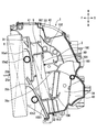
- FIG. 4 illustrates the air flow in the air conditioning case 2 shown in FIG.
- the flow of air in the vehicle interior in the first embodiment will be described with reference to FIGS. 1A to 4. Air from the defroster outlet 47 (FIG. 3) and the face outlet 48 flows above the vehicle interior.
- This air has a two-layer structure of inside and outside air, so it contains a lot of outside air that is fresh air.
- the air containing a lot of outside air is blown out to the driver's face and the like from the center face air outlets 48c and 48d and the side face air outlets 48a and 48b.
- the fresh fresh air with low humidity taken in from the outside air inlet 3 passes through the cooling heat exchanger 8 and the heating heat exchanger 9 in the air conditioning case 2 and then the defroster outlet 47.
- the defroster outlet 47 To prevent fogging of the windshield 46.
- inside air is introduce
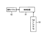
- the vehicle air conditioner 1 is automatically controlled by the air conditioning controller 51 of FIG. 1B.
- the air-conditioning control device 51 is a so-called ECU, and is configured by a microcomputer or the like, and controls various air-conditioning devices provided in the air-conditioning blower case 21 and the air-conditioning case 2 according to a preset program. is there.
- the air conditioning control device 51 is supplied with power from an in-vehicle battery (not shown) when an ignition switch (not shown) of an engine mounted on the vehicle is turned on.
- the air conditioning control device 51 receives a sensor signal from the sensor group 53 and an operation signal from the air conditioning operation panel 52 installed in the instrument panel in front of the passenger compartment.
- the sensor group 53 includes an outside air temperature sensor that detects an outside temperature (outside air temperature) Tam and an inside air temperature sensor that detects the inside temperature (inside air temperature) Tr.
- the solar radiation sensor which detects the solar radiation amount Ts in a vehicle interior, the temperature sensor after the heat exchanger for cooling which detects the blowing air temperature TE of the heat exchanger 8 for cooling, and the hot water temperature Tw to the heat exchanger 9 for heating A water temperature sensor to be detected is included.
- the operation panel 52 is provided with a temperature setting switch for setting a set temperature (Tset), a blowing mode setting switch, an inside / outside air mode setting switch, an air conditioning mode setting switch, and the like.
- the drive motor for the above-described inside / outside air switching door 6 the drive motor for the air-conditioning blower 7, the first and second air mix doors 10, and the actuator mechanisms for various doors such as face doors and foot doors (not shown) are driven. Motors.
- the air conditioner control device 51 stores the air conditioner stored in the storage circuit in advance. Run the control program.
- the detection signal detected by the sensor group 53 and the operation signal of the operation panel 52 are read, and the well-known target air temperature (TAO) of the vehicle interior air is based on these signals. Is calculated.
- TAO target air temperature
- the air-conditioning control device 51 determines the control state of the fan drive motor that drives the air-conditioning blower 7 and various electric actuators of the air-conditioning case 2 based on the target blowing temperature (TAO), and the determined control state is obtained. Control signals are output to various actuators. Then, the routine of reading the detection signal and the operation signal ⁇ calculating the target blowing temperature (TAO) ⁇ determining a new control state ⁇ outputting the control signal is repeated.
- TEO target blowing temperature
- the control state of the driving motor of the air conditioner blower 7 is determined with reference to a control map stored in advance in the storage circuit based on the target blowing temperature (TAO). Specifically, the amount of blown air is controlled near the maximum amount with the control voltage output to the electric motor being maximized in the extremely low temperature range (maximum cooling range) and the extremely high temperature range (maximum heating range) of the target blowing temperature (TAO). As the target blowing temperature (TAO) approaches the intermediate temperature range, the amount of blown air is reduced.
- TEO target blowing temperature
- the electric actuators for the first and second air mix doors 10 are determined so that the opening degree of the first and second air mix doors 10 becomes the target opening degree (SW).
- the target opening degree (SW) is, for example, the blown air temperature TE of the cooling heat exchanger 8 detected by the cooling heat exchanger temperature sensor, the hot water temperature Tw of the engine cooling water detected by the water temperature sensor, and the like. Is calculated from
- the target opening degree (SW) 100 (%) is the maximum heating position (MaxHot) of the first and second air mix doors 10 and the first and second cold air bypass passages are fully closed, for heating.
- the heat exchanger 9 side is fully open.
- the electric actuator for the inside / outside air switching door 6 is determined by referring to a control map stored in advance in the air conditioning control device 51 based on the target outlet temperature (TAO).
- the outside air mode in which outside air is introduced is basically prioritized, but the inside air mode is selected during the maximum cooling when the target blowing temperature (TAO) is in a very low temperature range, and the target blowing temperature (TAO) is extremely high.
- the inside / outside air two-layer mode is selected at the time of maximum heating that is a region.
- the air outlet mode is sequentially switched from the face mode to the bi-level mode to the foot mode as the target air temperature (TAO) rises from the low temperature region to the high temperature region.
- TAO target air temperature
- the face mode is selected mainly during the summer cooling when the target air temperature (TAO) is in the low temperature range
- the bi-level mode is selected mainly during spring / autumn air conditioning where the target air temperature (TAO) is in the intermediate temperature region. Is done.
- the foot mode is mainly selected during cooling in winter when the target outlet temperature (TAO) is in a low temperature range.
- a vehicle interior humidity sensor may be provided, and the defroster mode may be selected when there is a high possibility that fogging will occur in the windshield from the detection value of the humidity sensor.
- the heat exchanger 9 for heating is arrange
- the sliding movement direction in the second guide groove 10b1 of the second air mix door 10b is inclined such that the slide lower end position is located on the vehicle rear side (heating heat exchanger 9 side) with respect to the slide upper end position.
- the slide lower end position of the second air mix door 10b is located on the vehicle rear side (heating heat exchanger 9 side) with respect to the slide movement range of the first air mix door 10a.
- the heating heat exchanger 9 is inclined to the same side as the sliding movement direction of the second air mix door 10b, and at least a part thereof is located immediately above the sliding movement range of the second air mixing door 10b. Are arranged to be. Therefore, the size of the air conditioning case 2 in the vehicle front-rear direction (horizontal direction) can be reduced.
- the slide lower end position of the 1st air mix door 10a is located in the vehicle back side (heating heat exchanger 9 side) and the downward side rather than the slide upper end position of the 2nd air mix door 10b, it is an air-conditioning case. 2 can be downsized in the vertical direction.
- first shaft mounting hole 10a2 of the first air mix door 10a is disposed adjacent to the upper tank of the heating heat exchanger 9.
- the second shaft attachment hole 10b2 of the second air mix door 10b is disposed adjacent to the lower tank 13c of the heat exchanger 9 for heating. Therefore, it can suppress that the distribution
- the vehicle air conditioner 1 of the first embodiment has an air conditioning case 2.
- the vehicle air conditioner 1 includes a cooling heat exchanger 8 that cools the inside air that is air in the vehicle interior and the outside air that is outside the vehicle interior in the air conditioning case 2, and the air flow direction downstream side of the cooling heat exchanger 8. And a heat exchanger 9 for heating.
- the vehicle air conditioner 1 is disposed between the cooling heat exchanger 8 and the heating heat exchanger 9, and controls the flow of the cold air that has passed through the cooling heat exchanger 8, thereby heating the cold air for heat exchange.
- the air mix door 10 (10a, 10b) which adjusts the grade of the heating by the vessel 9 is provided.
- the vehicle air conditioner 1 has an air outlet through which air whose temperature is adjusted by the air mix door 10 blows out toward the passenger compartment.
- the air outlet includes a defroster air outlet 47 that blows out toward the windshield 46, side face air outlets 48 a and 48 b, center face air outlets 48 c and 48 d, and a foot air outlet 50.
- the side face air outlets 48a and 48b and the center face air outlets 48c and 48d are branched by different ducts from the same opening 42 (FIG. 1A) of the air conditioning case, and are collectively referred to as the face air outlet 48. .
- the vehicle air conditioner 1 is disposed on the downstream side of the heating heat exchanger 9 in the air flow direction, and the air flow regulating wall 100 that guides the air emitted from the heating heat exchanger 9 to the outlets 47, 48, and 50. (101, 102, 103) as shown in FIG.
- the air flow of the cold air that has exited from the cooling heat exchanger 8 is controlled by the first and second air mix doors 10a and 10b. Then, a first path K1 (first passage) that passes through the inside of the heating heat exchanger 9 and flows in the upward direction U from the downstream side of the heating heat exchanger 9 to the defroster outlet 47 and the face outlet 48. Is formed.
- the cool air from the cooling heat exchanger 8 is controlled by the first and second air mix doors 10a and 10b so that it does not pass through the heating heat exchanger 9 (that is, the heating heat exchanger 9 Flow (bypass).
- This air forms a second path K ⁇ b> 2 (second passage) from above the heating heat exchanger 9 to the defroster outlet 47 and the face outlet 48.
- the air flow regulating wall 100 includes a guide plate 100 (a generic name of 101, 102, 103, etc.) for guiding the air flow on the downstream side of the heating heat exchanger 9.
- the guide plate 100 extends from the downstream side wall surface 90 of the heating heat exchanger 9 in the direction perpendicular to the downstream side in the air flow direction, and is curved and extends in the upward direction U.
- a first guide 101 is provided. The first guide 101 raises air in the first path K1 from the downstream side of the heating heat exchanger 9 in the upward direction U and guides it to the outlet.
- the first guide 101 is a guide for forming a first path. 4 illustrates the configuration of the air conditioning case 2 to which the heating heat exchanger 9 is not attached. Therefore, the downstream side wall surface 90 of FIG. 4 is the same as the downstream side wall surface 90 of the heating heat exchanger 9. The position where it is arranged is shown.
- the guide plate 100 does not pass through the inside of the heating heat exchanger 9, and passes through the second path K ⁇ b> 2 from above the heating heat exchanger 9 to the defroster outlet 47 and the face outlet 48. It has a second guide 102 that affects it.
- the second guide 102 is provided along the right-angled direction from the upper end 9t1 of the heating heat exchanger 9 in order to hold other heat exchangers other than the cooling heat exchanger 8 and the heating heat exchanger 9. It extends downstream and is curved and extends in the downward direction D.
- the tip 101t1 of the first guide 101 is disposed at a location farther from the heating heat exchanger 9 than the tip 102t1 of the second guide 102.
- the distance between the tip 101 t 1 of the first guide 101 and the downstream side wall surface 90 of the heating heat exchanger 9 is greater than the distance between the tip 102 t 1 of the second guide 102 and the downstream side wall surface 90 of the heating heat exchanger 9.
- the guide plate 100 includes a third guide 103 that extends from the first guide 101 toward the tip 102t1 of the second guide 102.
- the third guide is a guide for suppressing contact heating air.
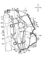
- FIG. 5 shows an enlarged part of FIG.
- the third guide 103 extends from the base portion 101 b that extends downstream in the air flow direction of the first guide 101 toward the tip 102 t 1 of the second guide 102.
- the dimension from the tip 103 t 1 of the third guide 103 to the tip 102 t 1 of the second guide 102 is displayed as a dimension A.
- the dimension from the tip 101t1 of the first guide 101 to the tip 102t1 of the second guide 102 is displayed as a dimension B.
- the dimension A is set in the range of 0.7 to 1.3 times the length of the dimension B.
- the magnitude relationship between the dimension A and the dimension B may be set to satisfy B ⁇ A ⁇ 1.3 ⁇ B.
- partition plates 25 (25 b, 25 c) that bisect the air flowing through the heating heat exchanger 9 into upper air and lower air flowing below the upper air are at least downstream of the cooling heat exchanger 8. Is provided. As shown in FIGS. 1A and 2, the partition plate 25 is also formed as a partition plate 25 a on the upstream side of the cooling heat exchanger 8 in order to obtain a two-layer structure of inside and outside air.
- the first guide 101 is formed between the partition plate 25 c on the downstream side of the heat exchanger 9 for heating and the second guide 102.
- the air conditioning case 2 of the first embodiment has an internal / external air two-layer structure in which air outside the vehicle flows above the partition plate 25 and internal air inside the vehicle flows below the partition plate 25.
- the cooling heat exchanger 8 is an evaporator that is cooled by evaporating the refrigerant.
- the heating heat exchanger 9 is composed of a heater core through which engine coolant flows. Instead of the heater core, either an electric heater that generates heat when energized or a condenser that generates heat when the refrigerant condenses can be employed.
- the said 1st Embodiment has the 1st path
- route K ⁇ b> 1 the cool air that has flowed out of the cooling heat exchanger 8 is controlled by the air mix door 10 to pass through the inside of the heating heat exchanger 9.
- the air heated by the heating heat exchanger 9 flows in the upward direction U from the downstream side of the heating heat exchanger 9 and reaches the openings 41 and 42.
- the second path K ⁇ b> 2 is a heating heat exchanger that does not pass (bypass) the cooling air from the cooling heat exchanger 8 through the heating heat exchanger 9 with the air flow controlled by the air mix door 10. 9 reaches the outlet 48 and the like.
- a guide plate 100 (generic name of 101, 102, 103, etc.) that affects the air flow on the downstream side of the heat exchanger 9 for heating is provided.
- the guide plate 100 has a first guide 101 that extends downstream from the downstream side wall surface 90 of the heating heat exchanger 9 and is bent in the upward direction U in order to form the first path K1. Accordingly, the heated air that has exited the heating heat exchanger 9 is guided to the first path K1.
- the guide plate 100 has a second guide 102 that extends downstream from the upper end portion 9t1 of the heating heat exchanger 9 and is bent in the downward direction D to hold other heat exchangers. . Further, the tip 101 t 1 of the first guide 101 is formed farther from the heating heat exchanger 9 than the tip 102 t 1 of the second guide 102.
- the third guide 103 extends from the first guide 101 toward the tip 102t1 of the second guide 102 (and in parallel with the downstream side wall surface 90).
- the contact heating wind F1 is suppressed and the fluctuation
- the vehicle air conditioner 1 includes a direction changing unit that changes the flow direction of the cold air from the second path K2 toward the heat exchanger 9 for heating in the first path K1 to the air outlets 47 and 48.
- the direction changing unit includes a space 60 defined by the first guide 101 and the third guide 103 and configured by the first guide 101 and the third guide 103.
- the direction changing unit changes the flow direction of the cold air that has flowed into the space 60 along the second guide 102 from the second path K2 into the air outlets 47 and 48.
- the space 60 is located between the portion 101 a extending in the upward direction U of the first guide 101 and the third guide 103.
- the dimension from the tip 103t1 of the third guide 103 to the tip 102t1 of the second guide 102 is defined as dimension A.
- the dimension from the tip 101t1 of the first guide 101 to the tip 102t1 of the second guide 102 is defined as dimension B.
- the dimension A is set in the range of 0.7 to 1.3 times the length of the dimension B.
- the dimensions A and B define the inlet and outlet dimensions for the downstream side wall surface 90 of the heating heat exchanger 9.
- the outgoing air is air passing through the first path K1.
- the entering air enters from between the tip 101 t 1 of the first guide 101 and the tip 102 t 1 of the second guide 102.
- the invading air becomes contact heating air F1 (two-dot chain line) heated by touching the downstream side wall surface 90 of the heat exchanger 9 for heating.
- the vertical dimension A is smaller than the front-rear dimension B (A ⁇ B)
- airflow resistance through the first path K1 becomes airflow resistance, the airflow is reduced, a preferable airflow distribution cannot be obtained, and blowing noise is generated. May grow.
- the magnitude relationship between the dimension A and the dimension B to be B ⁇ A ⁇ 1.3 ⁇ B, it is possible to suppress a reduction in air volume and blowing noise.
- the partition plate 25 (25b, 25c) which bisects the air which flows into the heat exchanger 9 for heating into upper air and the lower air which flows under the upper air is heat exchange for cooling It is provided downstream of the vessel 8.
- the 1st guide 101 is arrange
- warm air passing above the heat exchanger 9 for heating can be flowed along the first path K1 and blown out to the upper part of the vehicle interior. Further, the downward air flowing below the partition plate 25c on the downstream side of the heat exchanger 9 for heating can be blown out to the lower part of the passenger compartment.
- the upper air is outside air
- the lower air is inside air.
- the air-conditioning case 2 of the vehicle air conditioner according to the first embodiment employs a two-layer structure of inside and outside air. Therefore, the wind shield 46 shown in FIG. 3 has an excellent effect of preventing fogging, and the inside air can be circulated from the foot outlet 50 at the foot of the passenger to improve the heating efficiency.
- the cold air passage is divided into an upper side and a lower side centering on the heat exchanger.
- air flows into the space in front of the heat exchanger 9 for heating in the FACE mode MaxCool that blows the conditioned air cooled to the maximum extent from the face opening 42 through which air flows to the face air outlet 48. easy.
- the cooling heat exchanger 8 is composed of an evaporator that is cooled as the refrigerant evaporates, and the heating heat exchanger 9 is composed of a heater core through which engine cooling water flows.
- the third guide 103 extends from the first guide 101 toward the tip 102 t 1 of the second guide 102 in order to suppress the contact heating air F ⁇ b> 1.
- the third guide 103 extends in parallel with the downstream side wall surface 90 of the heating heat exchanger 9. Thereby, the contact heating air F1 is blocked by the third guide 103, the flow of the contact heating air F1 to the downstream side wall surface 90 of the heat exchanger 9 for heating is suppressed, and the temperature fluctuation of the air conditioning air can be suppressed. (Second Embodiment) Next, a second embodiment of the present disclosure will be described.
- FIG. 6 shows a second embodiment of the present disclosure.
- an electric heater serving as a heating auxiliary heat exchanger 9x constituting another heat exchanger is provided on the downstream side of the heating heat exchanger 9 serving as a heater core.
- This electric heater can control the amount of heat generated by switching the connection of a plurality of PTC heaters.
- FIG. 7 illustrates a third embodiment of the present disclosure.
- the vehicle air conditioner has a partition plate 25 (25a to 25c) that forms a two-layer structure of inside and outside air.
- the heating auxiliary heat exchanger 9x2 that constitutes a heat exchanger other than the cooling heat exchanger 8 and the heating heat exchanger 9 is provided below the partition plate 25, a heating auxiliary heat exchanger 9x2 that constitutes a heat exchanger other than the cooling heat exchanger 8 and the heating heat exchanger 9 is provided.
- the heating auxiliary heat exchanger 9x2 has an upper end held by the partition plate 25c and a lower end held by the lower end guide 104 bent in the upward direction U.
- the heating auxiliary heat exchanger 9x2 includes an electric heater or a condenser constituting a heat pump cycle.
- a slide door is used as the air mix door 10 which adjusts the air volume ratio of the warm air which passes the heat exchanger 9 for heating, and the cool air which bypasses the heat exchanger 9 for heating as an adjustment apparatus of blowing air temperature.
- a plate-like door that swings around the pivot may be used as the air mix door 10.
- the present disclosure is applied to a vehicle air conditioner having an internal / external air two-layer structure
- the internal / external air two-layer structure is an example and not an essential structure.
- three plate-shaped doors are used as a blowing mode door, instead of these three plate-shaped doors, one film-shaped blowing mode door which has a some opening part is used. Can be used.
Landscapes
- Physics & Mathematics (AREA)
- Thermal Sciences (AREA)
- Engineering & Computer Science (AREA)
- Mechanical Engineering (AREA)
- Air-Conditioning For Vehicles (AREA)
Abstract
Description
(第1実施形態)
以下、本開示の第1実施形態について図1Aないし図5を用いて詳細に説明する。図1Aは、本開示の第1実施形態を示す車両用空調装置1を模式的に示している。図2は、上記実施形態における車両用空調装置の空調ユニットの一部を示している。図2中、上下前後の各矢印は、車両搭載状態における上方方向U(車両天井方向)、下方方向D(車両床方向)、前方方向F(車両前進方向)、後方方向B(車両後進方向)を、夫々示している。この第1実施形態は、内気と外気を別々の通風路で送風することができる内外気2層構造を採用した車両用空調装置1である。
(第2実施形態)
次に、本開示の第2実施形態について説明する。なお、以降の各実施形態においては、上述した第1実施形態と同一の構成要素には同一の符号を付して説明を省略し、異なる構成について説明する。なお、第2実施形態以下については、第1実施形態と同じ符号は、同一の構成を示すものであって、先行する説明が援用される。
(第3実施形態)
次に、本開示の第3実施形態について説明する。上述した実施形態と異なる部分を説明する。図7は、本開示の第3実施形態を示している。図7において、車両用空調装置は内外気2層構造を形成する仕切り板25(25a~25c)を有する。
Claims (9)
- 車室内の空気である内気および車室外の空気である外気を冷却する冷却用熱交換器(8)と、
前記冷却用熱交換器(8)の空気流れ方向下流側に配置された加熱用熱交換器(9)と、
前記冷却用熱交換器(8)と前記加熱用熱交換器(9)との間に配置され、前記冷却用熱交換器(8)を通過した冷風の流れを制御することにより前記冷風の前記加熱用熱交換器(9)による加熱の程度を調整するエアミックスドア(10)と、
前記エアミックスドア(10)によって温度調整された空気が前記車室内に向けて吹出る吹出口(47、48、50)と、
前記加熱用熱交換器(9)の前記空気流れ方向下流側に配置され前記加熱用熱交換器(9)から出た空気を前記吹出口(47、48、50)に導く空気流れ規制壁(100)と、
前記冷却用熱交換器(8)から出た冷風が、前記エアミックスドア(10)の空気流れの前記制御により前記加熱用熱交換器(9)の内部を通過して前記吹出口(47、48)に至る第1経路(K1)と、
前記冷却用熱交換器(8)から出た冷風が、前記エアミックスドア(10)の空気流れの制御により前記加熱用熱交換器(9)の内部を通過しないで前記加熱用熱交換器(9)の上方から前記吹出口(47、48)に至る第2経路(K2)と、を備え、
前記空気流れ規制壁(100)は、前記加熱用熱交換器(9)の下流側の空気流れをガイドする複数のガイド板(100)を有し、
前記ガイド板(100)は、
前記加熱用熱交換器(9)の下流側壁面(90)から前記空気流れ方向下流側に延在し、かつ湾曲して上方方向(U)に延び、前記第1経路(K1)において空気を前記加熱用熱交換器(9)の下流側から前記上方方向(U)に流して前記吹出口(47、48)へ導く、第1ガイド(101)と、
前記加熱用熱交換器(9)の上方端部(9t1)から前記空気流れ方向下流側に延在し、かつ湾曲して下方方向(D)に延びる第2ガイド(102)と、
前記第1ガイド(101)から第2ガイド(102)の先端(102t1)に向けて延在する第3ガイド(103)と、を備え、
前記第1ガイド(101)の先端(101t1)と前記加熱用熱交換器(9)の前記下流側壁面(90)との距離は、前記第2ガイド(102)の前記先端(102t1)と前記加熱用熱交換器(9)の前記下流側壁面(90)との距離よりも長い車両用空調装置。 - 前記第3ガイド(103)の先端(103t1)から前記第2ガイド(102)の前記先端(102t1)までの寸法を寸法Aとし、前記第1ガイド(101)の前記先端(101t1)から前記第2ガイド(102)の前記先端(102t1)までの寸法を寸法Bとした場合に、前記寸法Aが、前記寸法Bの長さの0.7倍から1.3倍の範囲に設定されている請求項1に記載の車両用空調装置。
- 前記第3ガイド(103)の先端(103t1)から前記第2ガイド(102)の前記先端(102t1)までの寸法を寸法Aとし、前記第1ガイド(101)の前記先端(101t1)から前記第2ガイド(102)の前記先端(102t1)までの寸法を寸法Bとした場合に、
前記寸法Aと、前記寸法Bとの大小関係は、B≦Aである請求項1に記載の車両用空調装置。 - 前記冷却用熱交換器(8)の空気流れ方向下流側に設けられ、前記加熱用熱交換器(9)に流れる空気を上方空気と前記上方空気の下方を流れる下方空気とに二分する仕切り板(25)を、さらに備え、
前記上方方向において、前記仕切り板(25)と前記第2ガイド(102)との間に、前記第1ガイド(101)が配置されている請求項1ないし3のいずれか一項に記載の車両用空調装置。 - 前記仕切り板(25)より上方を流れる前記上方空気は前記外気であり、前記仕切り板(25)より下方を流れる前記下方空気は前記内気である内外気二層構造を有する請求項4に記載の車両用空調装置。
- 前記冷却用熱交換器(8)は冷媒が蒸発することにより吸熱する蒸発器を構成し、前記加熱用熱交換器(9)はエンジン冷却水が流れるヒータコア、通電により発熱する電気ヒータ、冷媒が凝縮することにより発熱する凝縮器のいずれかを構成する請求項1ないし5のいずれか一項に記載の車両用空調装置。
- 前記第3ガイド(103)は、前記第1ガイド(101)の前記空気流れ方向下流側に延びるベース部(101b)から前記第2ガイド(102)の前記先端(102t1)に向けて延びている請求項1ないし6のいずれか一項に記載の車両用空調装置。
- 車室内の空気である内気および車室外の空気である外気を冷却する冷却用熱交換器(8)と、
前記冷却用熱交換器(8)の空気流れ方向下流側に配置された加熱用熱交換器(9)と、
前記冷却用熱交換器(8)と前記加熱用熱交換器(9)との間に配置され、前記冷却用熱交換器(8)を通過した冷風の流れを制御することにより前記冷風の前記加熱用熱交換器(9)による加熱の程度を調整するエアミックスドア(10)と、
前記エアミックスドア(10)によって温度調整された空気が前記車室内に向けて吹出る吹出口(47、48、50)と、
前記加熱用熱交換器(9)の前記空気流れ方向下流側に配置され前記加熱用熱交換器(9)から出た空気を前記吹出口(47、48、50)に導く空気流れ規制壁(100)と、
前記冷却用熱交換器(8)から出た冷風が、前記エアミックスドア(10)の空気流れの前記制御により前記加熱用熱交換器(9)の内部を通過して前記吹出口(47、48)に至る第1経路(K1)と、
前記冷却用熱交換器(8)から出た冷風が、前記エアミックスドア(10)の空気流れの制御により前記加熱用熱交換器(9)の内部を通過しないで前記加熱用熱交換器(9)の上方から前記吹出口(47、48)に至る第2経路(K2)と、
前記第2経路(K2)から前記第1経路(K1)の前記加熱用熱交換器(9)へと向かう冷風の流れ方向を前記吹出口(47、48)へと転換する方向転換部と、を備え、
前記空気流れ規制壁(100)は、前記加熱用熱交換器(9)の下流側の空気流れをガイドする複数のガイド板(100)を有し、
前記ガイド板(100)は、
前記加熱用熱交換器(9)の下流側壁面(90)から前記空気流れ方向下流側に延在し、かつ湾曲して上方方向(U)に延び、前記第1経路(K1)において空気を前記加熱用熱交換器(9)の下流側から前記上方方向(U)に流して前記吹出口(47)へ導く、第1ガイド(101)と、
前記加熱用熱交換器(9)の上方端部(9t1)から前記空気流れ方向下流側に延在し、かつ湾曲して下方方向(D)に延びる第2ガイド(102)と、
前記第1ガイド(101)から第2ガイド(102)の先端(102t1)に向けて延在する第3ガイド(103)と、を備え、
前記第1ガイド(101)の先端(101t1)と前記加熱用熱交換器(9)の前記下流側壁面(90)との距離は、前記第2ガイド(102)の前記先端(102t1)と前記加熱用熱交換器(9)の前記下流側壁面(90)との距離よりも長く、
前記方向転換部は、前記第1ガイド(101)および前記第3ガイド(103)によって構成されるとともに、前記第1ガイド(101)および前記第3ガイド(103)によって区画された空間(60)を備え、
前記方向転換部は、前記第2経路(K2)から前記第2ガイド(102)に沿って前記空間(60)に流入してきた冷風の流れ方向を前記吹出口へと転換する車両用空調装置。 - 前記方向転換部の空間(60)は、前記第1ガイド(101)の上方方向(U)に延びる部分(101a)と第3ガイド103との間に位置している請求項8に記載の車両用空調装置。
Priority Applications (3)
| Application Number | Priority Date | Filing Date | Title |
|---|---|---|---|
| DE112014002797.9T DE112014002797B4 (de) | 2013-06-14 | 2014-06-03 | Klimaanlage für ein Fahrzeug |
| CN201480030179.3A CN105307880B (zh) | 2013-06-14 | 2014-06-03 | 车辆用空调装置 |
| US14/897,594 US9937768B2 (en) | 2013-06-14 | 2014-06-03 | Air conditioning device for vehicle |
Applications Claiming Priority (2)
| Application Number | Priority Date | Filing Date | Title |
|---|---|---|---|
| JP2013125965A JP5949677B2 (ja) | 2013-06-14 | 2013-06-14 | 車両用空調装置 |
| JP2013-125965 | 2013-06-14 |
Publications (1)
| Publication Number | Publication Date |
|---|---|
| WO2014199588A1 true WO2014199588A1 (ja) | 2014-12-18 |
Family
ID=52021906
Family Applications (1)
| Application Number | Title | Priority Date | Filing Date |
|---|---|---|---|
| PCT/JP2014/002918 Ceased WO2014199588A1 (ja) | 2013-06-14 | 2014-06-03 | 車両用空調装置 |
Country Status (5)
| Country | Link |
|---|---|
| US (1) | US9937768B2 (ja) |
| JP (1) | JP5949677B2 (ja) |
| CN (1) | CN105307880B (ja) |
| DE (1) | DE112014002797B4 (ja) |
| WO (1) | WO2014199588A1 (ja) |
Cited By (4)
| Publication number | Priority date | Publication date | Assignee | Title |
|---|---|---|---|---|
| CN109153313A (zh) * | 2016-05-18 | 2019-01-04 | 法雷奥日本株式会社 | 车辆用空调装置及其控制方法 |
| EP3569429A1 (en) * | 2018-05-15 | 2019-11-20 | Valeo Japan Co., Ltd. | Vehicular air conditioner |
| JP2021070396A (ja) * | 2019-10-30 | 2021-05-06 | 株式会社デンソー | 空調ユニット |
| WO2021084988A1 (ja) * | 2019-10-30 | 2021-05-06 | 株式会社デンソー | 空調ユニット |
Families Citing this family (10)
| Publication number | Priority date | Publication date | Assignee | Title |
|---|---|---|---|---|
| US9919576B2 (en) * | 2013-08-22 | 2018-03-20 | Hanon Systems | Air conditioner for vehicle and controlling method thereof |
| US10611209B2 (en) | 2017-01-04 | 2020-04-07 | Denso International America, Inc. | HVAC unit |
| CN110520313B (zh) * | 2017-04-20 | 2022-12-16 | 三菱电机株式会社 | 车辆空调设备 |
| JP2018192859A (ja) * | 2017-05-15 | 2018-12-06 | 三菱重工サーマルシステムズ株式会社 | 車両用空調装置 |
| DE112020002446B4 (de) | 2019-05-21 | 2023-12-14 | Hanon Systems | Klimaanlage für ein Fahrzeug |
| JP7321016B2 (ja) * | 2019-07-17 | 2023-08-04 | 株式会社ヴァレオジャパン | 車両用エアコン装置 |
| JP7327260B2 (ja) * | 2020-04-17 | 2023-08-16 | 株式会社デンソー | 車両用空調装置 |
| KR20220124967A (ko) * | 2021-03-04 | 2022-09-14 | 한온시스템 주식회사 | 차량용 공조장치 |
| KR20230100993A (ko) * | 2021-12-29 | 2023-07-06 | 한온시스템 주식회사 | 차량의 공조장치 |
| JP2023173928A (ja) * | 2022-05-27 | 2023-12-07 | ヴァレオ システム テルミク | 車両用空調装置 |
Citations (3)
| Publication number | Priority date | Publication date | Assignee | Title |
|---|---|---|---|---|
| JPH0558143A (ja) * | 1991-08-29 | 1993-03-09 | Nippondenso Co Ltd | 車両用空調装置 |
| JP2013014284A (ja) * | 2011-07-06 | 2013-01-24 | Denso Corp | 車両用空調装置 |
| JP2014080103A (ja) * | 2012-10-16 | 2014-05-08 | Denso Corp | 空調装置 |
Family Cites Families (18)
| Publication number | Priority date | Publication date | Assignee | Title |
|---|---|---|---|---|
| JPS588420A (ja) | 1981-07-03 | 1983-01-18 | Nippon Denso Co Ltd | カ−エアコンの操作案内方法 |
| DE10161751A1 (de) * | 2001-12-15 | 2003-06-18 | Behr Gmbh & Co | Heiz-oder Klimaanlage für ein Kraftfahrzeug |
| JP2004224180A (ja) | 2003-01-22 | 2004-08-12 | Denso Corp | 車両用空調装置 |
| US7819171B2 (en) * | 2004-01-28 | 2010-10-26 | Visteon Global Technologies, Inc. | Air conditioning system |
| JP2006103664A (ja) | 2004-09-08 | 2006-04-20 | Denso Corp | 車両用空調装置 |
| JP2006264382A (ja) | 2005-03-22 | 2006-10-05 | Denso Corp | 空調装置 |
| JP4600187B2 (ja) | 2005-07-11 | 2010-12-15 | 株式会社デンソー | 空調装置 |
| JP2007022484A (ja) * | 2005-07-21 | 2007-02-01 | Valeo Thermal Systems Japan Corp | 空調ユニットの温調ユニット部 |
| JP4286244B2 (ja) * | 2005-09-16 | 2009-06-24 | 株式会社ケーヒン | 車両用空調装置 |
| JP2007118753A (ja) * | 2005-10-27 | 2007-05-17 | Denso Corp | 空気通路開閉装置 |
| JP2007203888A (ja) | 2006-02-02 | 2007-08-16 | Denso Corp | 空調装置 |
| JP2008080889A (ja) * | 2006-09-26 | 2008-04-10 | Calsonic Kansei Corp | 車両用空気調和装置 |
| US8721408B2 (en) * | 2009-11-18 | 2014-05-13 | Keihin Corporation | Air conditioner for vehicle |
| JP2012040960A (ja) * | 2010-08-19 | 2012-03-01 | Keihin Corp | 車両用空気調和システム |
| JP5625993B2 (ja) * | 2011-02-22 | 2014-11-19 | 株式会社デンソー | 車両用空調装置 |
| JP5321647B2 (ja) | 2011-06-15 | 2013-10-23 | 株式会社デンソー | 冷凍サイクル装置 |
| DE102012205200B4 (de) | 2011-04-04 | 2020-06-18 | Denso Corporation | Kältemittelkreislaufvorrichtung |
| JP5585549B2 (ja) | 2011-07-16 | 2014-09-10 | 株式会社デンソー | 空調装置 |
-
2013
- 2013-06-14 JP JP2013125965A patent/JP5949677B2/ja active Active
-
2014
- 2014-06-03 WO PCT/JP2014/002918 patent/WO2014199588A1/ja not_active Ceased
- 2014-06-03 US US14/897,594 patent/US9937768B2/en active Active
- 2014-06-03 CN CN201480030179.3A patent/CN105307880B/zh active Active
- 2014-06-03 DE DE112014002797.9T patent/DE112014002797B4/de not_active Expired - Fee Related
Patent Citations (3)
| Publication number | Priority date | Publication date | Assignee | Title |
|---|---|---|---|---|
| JPH0558143A (ja) * | 1991-08-29 | 1993-03-09 | Nippondenso Co Ltd | 車両用空調装置 |
| JP2013014284A (ja) * | 2011-07-06 | 2013-01-24 | Denso Corp | 車両用空調装置 |
| JP2014080103A (ja) * | 2012-10-16 | 2014-05-08 | Denso Corp | 空調装置 |
Cited By (9)
| Publication number | Priority date | Publication date | Assignee | Title |
|---|---|---|---|---|
| CN109153313A (zh) * | 2016-05-18 | 2019-01-04 | 法雷奥日本株式会社 | 车辆用空调装置及其控制方法 |
| EP3459768A4 (en) * | 2016-05-18 | 2020-01-15 | Valeo Japan Co., Ltd. | VEHICLE AIR CONDITIONING AND CONTROL METHOD THEREFOR |
| CN109153313B (zh) * | 2016-05-18 | 2021-06-08 | 法雷奥日本株式会社 | 车辆用空调装置及其控制方法 |
| EP3569429A1 (en) * | 2018-05-15 | 2019-11-20 | Valeo Japan Co., Ltd. | Vehicular air conditioner |
| JP2021070396A (ja) * | 2019-10-30 | 2021-05-06 | 株式会社デンソー | 空調ユニット |
| WO2021084988A1 (ja) * | 2019-10-30 | 2021-05-06 | 株式会社デンソー | 空調ユニット |
| JP2021070397A (ja) * | 2019-10-30 | 2021-05-06 | 株式会社デンソー | 空調ユニット |
| WO2021084987A1 (ja) * | 2019-10-30 | 2021-05-06 | 株式会社デンソー | 空調ユニット |
| JP7211334B2 (ja) | 2019-10-30 | 2023-01-24 | 株式会社デンソー | 空調ユニット |
Also Published As
| Publication number | Publication date |
|---|---|
| US20160137022A1 (en) | 2016-05-19 |
| JP5949677B2 (ja) | 2016-07-13 |
| US9937768B2 (en) | 2018-04-10 |
| JP2015000646A (ja) | 2015-01-05 |
| DE112014002797T5 (de) | 2016-03-17 |
| CN105307880A (zh) | 2016-02-03 |
| DE112014002797B4 (de) | 2018-01-18 |
| CN105307880B (zh) | 2017-03-29 |
Similar Documents
| Publication | Publication Date | Title |
|---|---|---|
| JP5949677B2 (ja) | 車両用空調装置 | |
| JP5617779B2 (ja) | 車両用空調装置 | |
| JP4424409B2 (ja) | 車両用空調装置 | |
| JP5859427B2 (ja) | 車両用空調ユニット | |
| WO2016125731A1 (ja) | 車両用空調装置 | |
| JPH11235914A (ja) | 車両用空調装置 | |
| JP5131141B2 (ja) | 車両用空調装置 | |
| JP3978826B2 (ja) | 車両用空調装置 | |
| JPH09309322A (ja) | 自動車用空調装置 | |
| JP5353665B2 (ja) | 車両用空調装置 | |
| US20140048227A1 (en) | Vehicle air conditioning device | |
| JP2014237352A (ja) | 車両用空調装置 | |
| JP2006001378A (ja) | 車両用空調装置 | |
| JP4134846B2 (ja) | 車両用空調装置 | |
| JP4092820B2 (ja) | 車両用空調装置 | |
| JP4624773B2 (ja) | 車両用空調装置 | |
| JP2008222024A (ja) | 車両用空調装置 | |
| JP3997959B2 (ja) | 車両用空調装置 | |
| JP3812250B2 (ja) | 車両用空調装置 | |
| JP5459237B2 (ja) | 車両用空調装置 | |
| JP2009119912A (ja) | 車両用空調装置 | |
| JP2000238526A (ja) | 車両用空調装置 | |
| JP2005212608A (ja) | 車両用空調装置 | |
| JP2018127028A (ja) | 車両用空調ユニット | |
| JP4049958B2 (ja) | 自動車用空気調和装置 |
Legal Events
| Date | Code | Title | Description |
|---|---|---|---|
| WWE | Wipo information: entry into national phase |
Ref document number: 201480030179.3 Country of ref document: CN |
|
| 121 | Ep: the epo has been informed by wipo that ep was designated in this application |
Ref document number: 14810177 Country of ref document: EP Kind code of ref document: A1 |
|
| WWE | Wipo information: entry into national phase |
Ref document number: 14897594 Country of ref document: US |
|
| WWE | Wipo information: entry into national phase |
Ref document number: 112014002797 Country of ref document: DE |
|
| 122 | Ep: pct application non-entry in european phase |
Ref document number: 14810177 Country of ref document: EP Kind code of ref document: A1 |