WO2014156270A1 - 搬送用走行体の走行経路構造 - Google Patents
搬送用走行体の走行経路構造 Download PDFInfo
- Publication number
- WO2014156270A1 WO2014156270A1 PCT/JP2014/051802 JP2014051802W WO2014156270A1 WO 2014156270 A1 WO2014156270 A1 WO 2014156270A1 JP 2014051802 W JP2014051802 W JP 2014051802W WO 2014156270 A1 WO2014156270 A1 WO 2014156270A1
- Authority
- WO
- WIPO (PCT)
- Prior art keywords
- movable
- traveling body
- rails
- movable rails
- passage
- Prior art date
- Legal status (The legal status is an assumption and is not a legal conclusion. Google has not performed a legal analysis and makes no representation as to the accuracy of the status listed.)
- Ceased
Links
Images


Classifications
-
- B—PERFORMING OPERATIONS; TRANSPORTING
- B61—RAILWAYS
- B61J—SHIFTING OR SHUNTING OF RAIL VEHICLES
- B61J1/00—Turntables; Traversers; Transporting rail vehicles on other rail vehicles or dollies
-
- B—PERFORMING OPERATIONS; TRANSPORTING
- B61—RAILWAYS
- B61B—RAILWAY SYSTEMS; EQUIPMENT THEREFOR NOT OTHERWISE PROVIDED FOR
- B61B13/00—Other railway systems
- B61B13/12—Systems with propulsion devices between or alongside the rails, e.g. pneumatic systems
- B61B13/125—Systems with propulsion devices between or alongside the rails, e.g. pneumatic systems the propulsion device being a rotating shaft or the like
-
- B—PERFORMING OPERATIONS; TRANSPORTING
- B65—CONVEYING; PACKING; STORING; HANDLING THIN OR FILAMENTARY MATERIAL
- B65G—TRANSPORT OR STORAGE DEVICES, e.g. CONVEYORS FOR LOADING OR TIPPING, SHOP CONVEYOR SYSTEMS OR PNEUMATIC TUBE CONVEYORS
- B65G49/00—Conveying systems characterised by their application for specified purposes not otherwise provided for
- B65G49/02—Conveying systems characterised by their application for specified purposes not otherwise provided for for conveying workpieces through baths of liquid
- B65G49/04—Conveying systems characterised by their application for specified purposes not otherwise provided for for conveying workpieces through baths of liquid the workpieces being immersed and withdrawn by movement in a vertical direction
- B65G49/0409—Conveying systems characterised by their application for specified purposes not otherwise provided for for conveying workpieces through baths of liquid the workpieces being immersed and withdrawn by movement in a vertical direction specially adapted for workpieces of definite length
- B65G49/0436—Conveying systems characterised by their application for specified purposes not otherwise provided for for conveying workpieces through baths of liquid the workpieces being immersed and withdrawn by movement in a vertical direction specially adapted for workpieces of definite length arrangements for conveyance from bath to bath
- B65G49/044—Conveying systems characterised by their application for specified purposes not otherwise provided for for conveying workpieces through baths of liquid the workpieces being immersed and withdrawn by movement in a vertical direction specially adapted for workpieces of definite length arrangements for conveyance from bath to bath along a continuous circuit
- B65G49/0445—Conveying systems characterised by their application for specified purposes not otherwise provided for for conveying workpieces through baths of liquid the workpieces being immersed and withdrawn by movement in a vertical direction specially adapted for workpieces of definite length arrangements for conveyance from bath to bath along a continuous circuit the circuit being movable vertically as a whole
Definitions
- the present invention relates to a travel route structure of a transport traveling body provided with a travel route so as to cross a passage on a floor surface.
- Patent Document 2 is not the travel path of the transport traveling body, as a countermeasure when the conveyor disposed on the floor as the same transport means crosses the crossing passage.
- the conveyor portion intersecting the transverse passage is separated from the conveyors before and after the transverse passage so as to be horizontally rotatable, and when the transverse passage is used, the horizontally rotatable conveyor portion is arranged on the lateral side of the transverse passage. It is known to move horizontally.
- the configuration of the conveyor described in Patent Document 2 is replaced with a guide rail that configures the travel path of the transport traveling body, a large automobile body is transported in the automobile assembly line.
- the guide rail that constitutes the travel route of the transport traveling body is wide in width between the pair of left and right guide rails, and supports and guides the heavy transport travel body including the object to be transported. Therefore, a guide rail portion that intersects with a wide transverse passage through which a vehicle or the like can pass, that is, a guide rail portion configured to be horizontally rotatable becomes very large and heavy.
- this guide rail portion is configured to be horizontally rotatable, it is not only difficult to manually open and close, but also the inertia when horizontally moved increases, so that the connecting action position and retraction The impact at the time of stopping with the position opening / closing limit stopper also increases, and an opening / closing limit stopper that can withstand this is also required.
- the present invention proposes a travel route structure of a transport traveling body that can solve the above-described conventional problems, and the travel route structure of the transport traveling body according to the present invention will be described later.
- the reference numerals used in the description of the embodiment are shown in parentheses and are composed of guide rails (9a, 9b) disposed on the floor surface.
- the region intersecting the crossing passage (14) of the travel route of the transport traveling body (1) is a connecting action position connecting the guide rails (9a, 9b) before and after the crossing passage (14) and the crossing passage ( 14) is a travel path structure of a transport traveling body composed of a movable rail that can be opened and closed horizontally with respect to a lateral side retreat position, wherein the movable rail is in the connection action position. It consists of two movable rails (15, 16) before and after the series, and each movable rail (15, 16) At each outer end located outside the path (14), it is pivotally supported around the vertical support shaft (19, 21) so as to be horizontally rotatable, and is located at the connecting action position of both movable rails (15, 16). In some cases, a lock means (28) for connecting inner end portions adjacent to each other is provided.
- the length of each of the two movable rails configured to be horizontally rotatable is half of the length of the open / close region intersecting with the transverse passage of the travel path of the transport traveling body. Even if the entire movable rail in the open / close region is large and heavy, each of the two movable rails that are opened and closed is half the size and weight, so it is easy to open and close manually. In addition, the impact at that time is halved even when it is stopped by the opening / closing limit stopper, and the adverse effects on operation and cost are reduced. In addition, when both movable rails are closed at the connecting action position, the inner ends of these movable rails are connected to each other by the locking means. Compared to the case of fixing, not only one locking means is required, but also the inner ends of the guide rails of both movable rails can be reliably held in a connected state.
- the two front and rear movable rails (15, 16) may be configured to be opened to the opposite sides, but have a double door structure that can be opened and closed only on the same side with respect to the travel route, and the locking means ( 28) can be provided on the side of the movable rail (15, 16) on both sides of the left and right sides on the opening side to the retracted position.
- the vertical support shaft serving as the pivot point of both movable rails and the locking means are concentrated on one side of the travel path, so it is convenient for maintenance work on the vertical support shaft serving as the pivot point and the locking means.
- the engagement / disengagement operation of the locking means and the opening / closing operation of each movable rail can be performed intensively on one side of the travel route, and workability compared to the case where operation on both sides of the travel route is required. And the safety is improved.
- the transport traveling body (1) moves toward the crossing passage (14) when the movable rails (15, 16) are in the retracted position.
- a movable stopper piece (44) for preventing the movement is provided, and each movable rail (15, 16) is provided with an operation cam for switching the movable stopper piece (44) to a non-acting position when it is in the connection acting position ( 45) can be provided.
- the movable stopper piece when the movable rail is closed and returned to the connection operation position, the movable stopper piece is automatically switched to the non-operation position by using the movement of the movable rail.
- the movable stopper piece when it is necessary to return to the non-operating position, there is no possibility of damaging the movable stopper piece when forgetting the human operation and starting the traveling traveling body for transportation.
- the lock means (28) and the retracted state lock means (34, 35) may be of any configuration, but both movable rails (15, 16) are arranged so as to overlap each other when both movable rails (15, 16) are in the connecting action position. (15, 16) and the upper and lower plate members (29), (30), and the upper and lower plate members (29, 30), and the locking pins that are inserted between the through holes (29a, 30a). (31) constitutes the locking means (28), and the retracted state locking means (34, 35) overlaps the upper plate (29) and the lower plate (30) of each movable rail (15, 16).
- the locking pin (31, 34b) inserted over at least the upper and lower plate members of the locking means are also used as a part of the retracted state locking means.
- the locking pins of the locking means are also retracted Since it can be used as one of the two locking pins required for the state locking means, both the locking means and the retracted state locking means can be implemented at a low cost by reducing the total number of parts. .
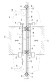
- FIG. 1 is a side view of a transport traveling body.
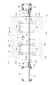
- FIG. 2 is a partially cut-away plan view showing a transporting traveling body and a transverse passage.
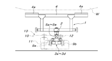
- FIG. 3 is a front view of the transport traveling body.
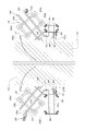
- FIG. 4 is a plan view showing the configuration of the travel route of the transport traveling body at the intersection with the transverse passage.
- 5A is a side view of FIG. 4, and
- FIG. 5B is a longitudinal sectional view of the movable rail.
- FIG. 6 is a plan view showing a state where the movable rails shown in FIG. 4 are opened.
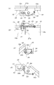
- FIG. 7A is a plan view showing the locking means for locking the pair of movable rails at the connection action position
- FIG. 7B is a longitudinal side view of the locking means
- FIG. 7C is a retracted state in which one movable rail is locked at the retracted position.
- FIG. 7D is a plan view of the retracted state locking means for locking the other movable rail at the retracted position.
- FIG. 8 is a plan view of the main part showing the movable rail and the conveyance traveling body stopper.
- 9A is a cross-sectional view taken along the line XX of FIG. 8
- FIG. 9B is a cross-sectional view taken along the line XX of FIG. 8 showing the conveyance traveling body stopper when the movable rail rotates.
- the transport traveling body 1 includes a load bar 2 that is longer than the entire length of the transported object W, A plurality of trolleys 3a to 3d that support the load bar 2 and a cart body 4 that is supported by a pair of front and rear load trolleys 3a and 3b at an intermediate position among the trolleys.
- the load bar 2 includes a central load bar unit 5a located between a pair of front and rear load trolleys 3a and 3b, front and rear end load bar units 5b and 5c integrated with front and rear end guide trolleys 3c and 3d, and front and rear end load bar units 5b.
- the central load bar unit 5a is connected to the front and rear two intermediate load bar units 5d, 5e to enable the transport traveling body 1 to travel along the horizontal curve path and the up-and-down gradient path unit.
- the vertical swing joints 6a and 6b and the horizontal swing joints 7a and 7b are interposed at the connection points between the central load bar single unit 5a and the intermediate load bar single units 5d and 5e.
- Horizontal oscillating joints 7c and 7d are interposed at connecting portions between 5d and 5e and the front and rear load bar units 5b and 5c.
- the pair of front and rear support members 8a and 8b that support the cart body 4 are concentrically integrated with the vertical support shafts of the horizontal swing joints 7a and 7b between the central load bar unit 5a and the intermediate load bar units 5d and 5e. And the lower ends thereof are connected to the load trolleys 3a, 3b via horizontal support shafts that are laterally directed to the left and right.
- a transported object support base 4 a that supports a transported object W such as an automobile body is provided.
- the travel path of the transport traveling body 1 is composed of a pair of left and right guide rails 9a and 9b that support and guide the trolleys 3a to 3d, and the load bar 2 is a friction drive surface whose side faces are continuous over the entire length. Yes. Therefore, in the travel route, a load is applied between the friction drive wheel 10 that is in pressure contact with the side surface (friction drive surface) of the load bar 2, the motor 11 that rotationally drives the friction drive wheel 10, and the friction drive wheel 11.
- a friction drive unit 13 including a backup roller 12 sandwiching the bar 2 is also provided.
- an equal interval travel section in which each transport travel body 1 travels at a constant speed at an arbitrary interval, and the rear transport travel body 1
- a thrust travel section in which each transport traveling body 1 travels in a daisy chain is set.
- the friction drive units 13 are arranged at equal intervals shorter than the entire length of the load bar 2 along the travel path of the transport traveling body 1, and in the thrust travel section, the entrance and the exit thereof.
- a friction drive unit 13 is disposed.
- a crossing passage 14 that intersects with the travel route may be provided.
- the transverse passage 14 has a passage width that is sufficiently shorter than the entire length of the load bar 2 in the transport traveling body 1, and the friction drive units 13 that are arranged at regular intervals in the equally-spaced traveling section are arranged before and after the transverse passage 14. It is distributed to. Therefore, when the crossing passage 14 is used, the rear end of the load bar 2 of the transport traveling body 1 traveling in the crossing passage 14 is separated from the friction drive unit 13a on the upper side of the crossing passage 14.
- FIGS. 4 to 9 The configuration of the travel route portion of the transport traveling body 1 that intersects the crossing passage 14 will be described with reference to FIGS. 4 to 9.
- the area intersecting with the transverse passage 14 is replaced with a pair of front and rear movable rails 15 and 16.
- Each of the movable rails 15 and 16 is constructed by laying a pair of left and right guide rails 15a and 15b and 16a and 16b having the same required length as the guide rails 9a and 9b on the movable bases 17 and 18, respectively.
- the movable rail 15 on the upper side is connected to the end of the guide rail 9a to which the guide rail unit 15a on one side is connected to the upper side, and the outer side of the guide rail unit 15a and the guide rail 9a (the side on which the guide rail 9b is located).
- Wheels 20a to 20d that are fixed in the direction of rolling on the floor surface are respectively provided at the four corners of the bottom of the movable base 17, respectively. Is attached in such a direction that the extension line of the axial center in a plan view intersects the axial center of the vertical support shaft 19.
- the movable rail 16 on the lower side is connected to the end of the guide rail 9a to which the single guide rail 16a is connected to the lower side, and the outer side of the guide rail 9a and the guide rail 9a (the side on which the guide rail 9b is located).
- Wheels 22a to 22d which are fixed in the direction of rolling on the floor surface, are respectively connected to the four corners of the bottom of the movable base 18.
- the extension line of the axial center in the plan view is attached so as to intersect with the axial center of the vertical support shaft 21.
- these fixed wheels 20a to 20d and 22a to 22d it is also possible to use universal wheels.
- the movable rails 15 and 16 are connected to the guide rails 15a and 15b and 16a and 16b, and the upper and lower guide rails 9a and 9b are connected to the guide rails 15a and 15b.
- 16a and 16b are in the connecting action position where they are connected in a straight line, the stop plate 23a that abuts on the outer side of the upper end of the guide rail unit 15b of the movable rail 15 (the side opposite to the side where the guide rail unit 15a is located).
- Reference numeral 24 denotes a stop plate fixed to the outer end of the guide rail unit 15 b of the movable rail 15 and receives the end of the guide rail unit 16 b of the movable rail 16. Therefore, the movable rails 15 and 16 can only be rotated horizontally (horizontal opening) from the connecting action position to the side where the guide rail units 15a and 16a are located with respect to the guide rail units 15b and 16b.
- connection point between the guide rail unit 15a of the movable rail 15 and the upper guide rail 9a, that is, the connection point 25a adjacent to the vertical support shaft 19 is provided.
- the connecting portion 25b between the guide rail unit 15b and the upper guide rail 9b is slightly shifted to the traveling direction side of the conveying traveling body 1, that is, the side where the crossing passage 14 is present, and the guide rail of the movable rail 16
- the connection point between the single unit 16a and the upper guide rail 9a that is, the connection point 26a adjacent to the vertical support shaft 21
- the connection point 26b between the guide rail unit 16b and the lower guide rail 9b The body 1 is slightly shifted to the side opposite to the traveling direction side, that is, the side where the cross passage 14 is located.
- connection portion 27a between the guide rails 15a and 16a and the connecting portion 27b between the guide rails 15b and 16b in the movable rails 15 and 16 are also shifted from each other in the traveling direction of the transport traveling body 1.
- connection portion 27b between the guide rail units 15b and 16b is slightly shifted in the traveling direction of the transport traveling body 1 with respect to the connection portion 27a between the guide rail units 15a and 16a.
- the shifting of the positions of the rail-to-rail connecting portions 25a to 27b that form the left and right pairs is based on the rails that the left and right rollers of the trolleys 3a to 3d of the transporting traveling body 1 that travels on the transverse passage 14 form a left and right pair. This is in order to suppress the occurrence of shocks and abnormal noises that the traveling body 1 receives when passing through the inter-connection points at the same time.
- the end of the rail that forms the connection points 25a, 25b, 27a, and 27b far from the vertical support shaft 19 in the plan view proceeds in the traveling direction of the transport traveling body 1.
- connection portions 26a and 26b are in a direction in which the end closer to the vertical support shaft 21 advances in the traveling direction of the transport traveling body 1 in plan view. It is formed obliquely so as to be displaced.
- a locking means 28 for locking both the movable rails 15 and 16 to the connecting action position.
- the locking means 28 is fixed to the upper surface of the free end portion of the guide rail unit 16a of the lower-side movable rail 16 and extends to the outer side of the free end portion of the guide rail unit 15a of the upper-side movable rail 15.
- the lower plate 30 and the upper and lower plates 29 and 30 overlapped with each other so as to overlap with the lower side of the upper plate 29 so as to be fixed to the outside of the free end portion of the guide rail 15a of the upper movable rail 15.
- the locking pin 31 is inserted into the through holes 29 a and 30 a concentrically provided in the part and received on the upper surface of the upper plate 29.
- Reference numeral 32 denotes a string-like connecting material such as a chain, a wire, and a rope for connecting the locking pin 31 to the base of the upper plate 29.
- the upper plate member 29 is provided with a preliminary through hole 33 for supporting the locking pin 31 extracted from the through holes 29a and 30a.
- the movable rails 15, 16 are horizontally moved around the vertical support shafts 19, 21 to the connection action positions received by the stop plates 23 a, 23 b, 24.
- the locking pin 31 is inserted into the through holes 29a, 30a of the upper and lower plate members 29, 30 overlapping the upper and lower sides of the lock means 28, and the movable rails 15, 16 are connected to each other to lock the horizontally swingable lock.
- the transport traveling body 1 in which the trolleys 3a to 3d are supported and guided by the guide rails 9a and 9b is traversed via the guide rails 15a to 16b of the movable rails 15 and 16 in the connected state.
- the vehicle can pass through the passage 14 without any problem.
- the friction drive unit 13 on the upper side of the crossing passage 14 is stopped at the timing described above, and the conveying traveling body 1 from within the crossing passage 14 is stopped. 6 withdrawn to the lower side, the lock pin 31 of the lock means 28 is pulled out to release the lock, and the lock pin 31 is inserted into the preliminary through-hole 33 of the upper plate 29 as required. As shown, the movable rails 15 and 16 are moved horizontally around the vertical support shafts 19 and 21 to switch to the retracted position outside the transverse passage 14. As a result, the crossing passage 14 is opened, so that the vehicle or the like can safely travel on the crossing passage 14 that crosses the travel route of the transport traveling body 1.
- the opening operation of the movable rails 15 and 16 must be performed simultaneously or after the lower-side movable rail 16 is opened in advance, the upper-side movable rail 15 is opened.
- both the movable rails 15 and 16 are closed to the original connecting action position in the reverse procedure of the opening operation.
- the movable rails 15 and 16 may be connected to each other by the lock means 28.
- the retracted state locking means 34 for the movable rail 15 is a guide rail when the movable rail 15 is opened to the retracted position as shown in FIG. 7C.
- the locking plate 34a comprises a locking plate 34a and a locking pin 34b that overlap on the lower plate 30 fixedly protruding from the free end of the unit 15a.
- the locking plate 34a is fixedly projected horizontally from the upper end portion of the column member 37 erected on the base plate 36 fixed on the floor surface, and the vertical penetration provided in the locking plate 34a.
- the movable rail 15 is locked in the retracted position by inserting the locking pin 34b across the hole and the through hole 30a provided in the lower plate 30 on the movable rail 15 side.
- the locking pin 34b is supported on the locking plate 34a in an inserted state, and is connected to a support member 37 (or the locking plate 34a) by a string-like connecting material 38 such as a chain, a wire, or a rope. It is.
- the retracted state locking means 35 for the movable rail 16 is located below the upper plate 29 that is fixedly projected on the outside of the free end of the guide rail unit 16a when the movable rail 16 is moved to the retracted position. It is composed of an overlapping locking plate 39 and a locking pin 31 of the locking means 28.
- the locking plate 39 is fixedly projected horizontally from the upper end portion of the column member 41 erected on the base plate 40 fixed on the floor surface, and the vertical penetration provided in the locking plate 39 is provided.
- the movable rail 16 is locked in the retracted position by inserting the locking pin 31 across the hole and the through hole 29a provided in the upper plate 29 on the movable rail 16 side.
- stoppers for receiving the movable rails 15 and 16 at the retracted position (opening limit position) when the movable rails 15 and 16 are opened to the retracted position are not shown, It is desirable to provide the stopper using the column members 37, 41 and the like.
- the transport traveling body 1 does not travel toward the crossing passage 14 in principle, but due to some unexpected situation
- the transport traveling body 1 starts to move, and the front end guide trolley 3c (the rear end guide trolley when the transport traveling body 1 travels backward unexpectedly from the end portion of the guide rails 9a, 9b, which is interrupted at the crossing passage 14, to the crossing passage 14 side.
- the front end guide trolley 3c the rear end guide trolley when the transport traveling body 1 travels backward unexpectedly from the end portion of the guide rails 9a, 9b, which is interrupted at the crossing passage 14, to the crossing passage 14 side.
- 3d falls off.
- automatic stopper devices 42 and 43 are provided at the upper and lower travel path ends of the movable rails 15 and 16, respectively. Can be attached.
- Both automatic stopper devices 42 and 43 have the same structure, and as shown in FIG. 8 and FIG. 9, on the inner side of the end portion of the guide rail 9b connected to the guide rail single bodies 15b and 16b of the movable rails 15 and 16, respectively.
- the movable stopper piece 44 is provided, and an operation cam 45 provided on the inner side of the end portions of the guide rail units 15b and 16b of the movable rails 15 and 16 adjacent to the end portion of the guide rail 9b.
- the movable stopper piece 44 is fixed to a vertical substrate 46 attached to the outside of the guide rail 9b, and is supported by a horizontal support shaft 48 horizontally and horizontally on a bearing 47 that protrudes horizontally below the guide rail 9b.
- the cam driven roller 49 is pivotally supported by a horizontal pivot that is laterally directed to the end of the movable rails 15 and 16 and the movable rails 15 and 16 are moved to the retracted position.
- the cam driven roller 49 is tilted so that the side of the cam driven roller 49 is lowered by the weight of the cam driven roller 49 (a spring may be used in combination).
- the stopper pin 50 protruding from the movable stopper piece 44 comes into contact with the lower surface of the guide rail 9b.
- the working end 44a of the movable stopper piece 44 opposite to the side where the cam follower roller 49 is located is the rollers (guides) of the front and rear guide trolleys 3c and 3d of the transport traveling body 1 shown in FIGS. It protrudes in the movement locus of the bearing portion of a roller that is fitted to the rails 9a and 9b and supported by a horizontal support shaft.
- An operation cam 45 provided inside the end portions of the guide rails 15b and 16b of the movable rails 15 and 16 is provided inside the support member 51 that is fixedly projected inward from the lower side of the ends of the guide rails 15b and 16b. At the end, it is attached so as to protrude from the end of the guide rail unit 15b, 16b to the side with the guide rail 9b, and when the movable rails 15, 16 are closed to the connecting action position shown in FIG.
- the cam follower roller 49 of the movable stopper piece 44 is lifted, and the movable stopper piece 44 is rotated against the gravity around the horizontal support shaft 48 in the direction in which the action end 44a is lowered, and the action end 44a is conveyed.
- the traveling body 1 is retracted below the traveling route.
- the crossing is performed.
- the movable stopper pieces 44 of the automatic stopper devices 42 and 43 disposed at the ends of the travel path before and after the passage 14 are held at the non-operating position retracted below the travel path of the transport traveling body 1. Therefore, the transport traveling body 1 can travel over the crossing passage 14 via the movable rails 15 and 16 without being influenced by the presence of the automatic stopper devices 42 and 43 at all.
- the movable stopper piece 44 of the automatic stopper devices 42 and 43 is automatically switched to the operating position,
- the end adjacent to the crossing passage 14 of the travel route separated by the passage 14 is closed, and temporarily the transport traveling body 1 on the travel route on both sides of the crossing passage 14 causes the crossing passage for some reason. Even if it moves to the 14 side unexpectedly, the front end guide trolley 3c or the rear end guide trolley 3d of the traveling body 1 for conveyance can be received by the action end 44a of the movable stopper piece 44 and forcibly stopped.
- the pair of front and rear movable rails 15 and 16 are configured to be openable and closable on the same side of the travel route, but the guide rails 15a and 15b and the guide rail 16a of the movable rails 15 and 16 are configured. 16b, the movable rail 15 is opened and closed on the left side of the travel route, and the movable rail 16 is opened and closed on the right side of the travel route. Is also possible.
- the opening / closing operation of the movable rails 15 and 16 can be performed manually by an operator. However, in some cases, a power source such as a motor is separately used, and the movable rails 15 and 16 are replaced by human power. It can also be opened and closed.
- the configuration of the locking means 28 for connecting the inner end portions of the two movable rails 15 and 16 closed at the connecting action position is not limited to that of the above embodiment.
- a long pin is used as the locking pin 31, and a hole is formed on the floor surface side where the lower end of the locking pin 31 inserted into the through holes 29a, 30a of the upper and lower plate members 29, 30 is inserted.
- the position of the inner ends can be fixed to the floor surface.
- the lock means 28 that switches to the locked state by human operation
- the automatic lock that automatically engages when both the movable rails 15 and 16 are closed to the connecting action position (closed limit position) in series. It can also be a means.
- the unlocking operation of the locking means 28 is not limited to manual operation. When specific conditions are met, such as a human switch operation in a situation where safety is confirmed, an appropriate operation such as a cylinder unit or a solenoid is performed.
- the lock means can be automatically unlocked by a simple actuator. When providing the locking means having such an automatic unlocking function, it is desirable that the two movable rails 15 and 16 are opened by power in a predetermined order as described above.
- the travel route structure of the transport traveling body of the present invention is a layout in which a transverse passage is provided so as to intersect the travel route of the transport traveling body traveling on a guide rail laid on the floor surface. It can be used as a means for safely passing other vehicles.
Landscapes
- Engineering & Computer Science (AREA)
- Chemical & Material Sciences (AREA)
- Combustion & Propulsion (AREA)
- Transportation (AREA)
- Mechanical Engineering (AREA)
- Platform Screen Doors And Railroad Systems (AREA)
- Intermediate Stations On Conveyors (AREA)
Priority Applications (2)
| Application Number | Priority Date | Filing Date | Title |
|---|---|---|---|
| CN201480018265.2A CN105307916B (zh) | 2013-03-28 | 2014-01-28 | 搬运用行走体的行走路径结构 |
| US14/815,456 US9630634B2 (en) | 2013-03-28 | 2015-07-31 | Traveling route structure of conveying traveling body |
Applications Claiming Priority (2)
| Application Number | Priority Date | Filing Date | Title |
|---|---|---|---|
| JP2013-068432 | 2013-03-28 | ||
| JP2013068432A JP2014190114A (ja) | 2013-03-28 | 2013-03-28 | 搬送用走行体の走行経路構造 |
Related Child Applications (1)
| Application Number | Title | Priority Date | Filing Date |
|---|---|---|---|
| US14/815,456 Continuation US9630634B2 (en) | 2013-03-28 | 2015-07-31 | Traveling route structure of conveying traveling body |
Publications (1)
| Publication Number | Publication Date |
|---|---|
| WO2014156270A1 true WO2014156270A1 (ja) | 2014-10-02 |
Family
ID=51623272
Family Applications (1)
| Application Number | Title | Priority Date | Filing Date |
|---|---|---|---|
| PCT/JP2014/051802 Ceased WO2014156270A1 (ja) | 2013-03-28 | 2014-01-28 | 搬送用走行体の走行経路構造 |
Country Status (4)
| Country | Link |
|---|---|
| US (1) | US9630634B2 (enExample) |
| JP (1) | JP2014190114A (enExample) |
| CN (1) | CN105307916B (enExample) |
| WO (1) | WO2014156270A1 (enExample) |
Cited By (2)
| Publication number | Priority date | Publication date | Assignee | Title |
|---|---|---|---|---|
| CN104944097A (zh) * | 2015-06-26 | 2015-09-30 | 浙江特拉建材有限公司 | 一种用于输送砖块的输送装置 |
| JP2016142028A (ja) * | 2015-02-02 | 2016-08-08 | ニチユ三菱フォークリフト株式会社 | レールロック機構 |
Families Citing this family (8)
| Publication number | Priority date | Publication date | Assignee | Title |
|---|---|---|---|---|
| JP2014190114A (ja) * | 2013-03-28 | 2014-10-06 | Daifuku Co Ltd | 搬送用走行体の走行経路構造 |
| JP7054379B2 (ja) * | 2016-03-03 | 2022-04-13 | 村田機械株式会社 | 搬送システム |
| JP6501078B2 (ja) * | 2016-04-29 | 2019-04-17 | 株式会社ダイフク | 搬送用走行体利用の搬送設備 |
| DE102016120257B3 (de) * | 2016-10-24 | 2017-12-21 | Johannes Herbig | Schienenmodul mit Schienenabschnitten und mit einem Linearantrieb, Wagen für ein Schienenmodul und Schienentransportsystem |
| CN106865123A (zh) * | 2017-04-18 | 2017-06-20 | 中科富创(北京)科技有限公司 | 智能轨道 |
| CN113291728B (zh) * | 2021-05-28 | 2022-07-08 | 华北科技学院(中国煤矿安全技术培训中心) | 一种内嵌式轨道交通运输装置的支撑导轨机构 |
| CN113830205B (zh) * | 2021-09-02 | 2025-05-06 | 赛亚森汽车系统(上海)有限公司 | 一种汽车驾驶舱模块周转系统 |
| EP4400456A4 (en) * | 2022-11-22 | 2024-08-28 | Contemporary Amperex Technology Co., Limited | DISPENSING DEVICE AND AUTOMATED ASSEMBLY LINE |
Citations (4)
| Publication number | Priority date | Publication date | Assignee | Title |
|---|---|---|---|---|
| JPH082407A (ja) * | 1994-06-27 | 1996-01-09 | Nakanishi Kinzoku Kogyo Kk | 床コンベヤ |
| JPH1191915A (ja) * | 1997-09-20 | 1999-04-06 | Mori:Kk | 商品搬送装置 |
| JP2005343195A (ja) * | 2004-05-31 | 2005-12-15 | Toyota Motor Corp | 台車搬送装置 |
| JP2008238914A (ja) * | 2007-03-27 | 2008-10-09 | Daifuku Co Ltd | 台車式搬送設備 |
Family Cites Families (36)
| Publication number | Priority date | Publication date | Assignee | Title |
|---|---|---|---|---|
| US4438701A (en) * | 1981-02-20 | 1984-03-27 | Tsubakimoto Chain Company | Truck conveyor |
| US4440090A (en) * | 1981-02-20 | 1984-04-03 | Tsubakimoto Chain Company | Storage arrangement for truck conveyor trolleys |
| JPS61100663U (enExample) * | 1984-12-07 | 1986-06-27 | ||
| GB2182621B (en) * | 1985-11-11 | 1989-10-04 | Honda Motor Co Ltd | System and method for suspendingly transporting bodies |
| US5033394A (en) * | 1989-10-06 | 1991-07-23 | Mid-West Conveyor Company, Inc. | Floor conveyor junction seal gap closure |
| US5303655A (en) * | 1992-09-28 | 1994-04-19 | Mid-West Conveyor Company, Inc. | Automatic stabilizer unit for free trolley having vertically movable wheels resonsive to trackside rails |
| KR0183454B1 (ko) * | 1993-10-07 | 1999-04-15 | 마스다 쇼오이치로오 | 실어서 이송하는 장치 |
| JPH0848406A (ja) | 1994-08-04 | 1996-02-20 | Toyo Kanetsu Kk | コンベヤ装置 |
| US5544590A (en) * | 1995-09-14 | 1996-08-13 | Mid-West Conveyor Company | Automatic seal crossover system for power and free conveyor on-floor carriages |
| JP3879818B2 (ja) * | 2001-09-06 | 2007-02-14 | 株式会社ダイフク | 搬送装置 |
| JP3994711B2 (ja) * | 2001-10-01 | 2007-10-24 | 株式会社ダイフク | 搬送装置 |
| JP4557683B2 (ja) * | 2003-12-26 | 2010-10-06 | 株式会社大気社 | 搬送設備 |
| WO2006137317A1 (ja) * | 2005-06-22 | 2006-12-28 | Daifuku Co., Ltd. | 搬送用走行体の配送設備 |
| JP4453626B2 (ja) * | 2005-07-25 | 2010-04-21 | 株式会社ダイフク | 搬送設備 |
| JP4189685B2 (ja) * | 2005-08-04 | 2008-12-03 | 株式会社ダイフク | 台車式搬送装置 |
| JP4314497B2 (ja) * | 2007-01-22 | 2009-08-19 | 株式会社ダイフク | 搬送用走行体の上下経路切換装置 |
| JP4895022B2 (ja) * | 2007-01-30 | 2012-03-14 | 株式会社ダイフク | 台車式搬送装置 |
| JP4978371B2 (ja) * | 2007-08-24 | 2012-07-18 | 株式会社ダイフク | 台車利用の搬送装置 |
| JP5020129B2 (ja) * | 2008-03-13 | 2012-09-05 | 株式会社ダイフク | コンベヤ上への車両移載装置 |
| JP5255906B2 (ja) * | 2008-05-23 | 2013-08-07 | 本田技研工業株式会社 | 車体に対する足回り部品の同期搬送装置及び同期搬送方法 |
| JP5099454B2 (ja) * | 2009-03-27 | 2012-12-19 | 株式会社ダイフク | 交差部切換設備 |
| JP5686501B2 (ja) * | 2009-03-27 | 2015-03-18 | 株式会社ダイフク | 物品搬送設備 |
| JP5212836B2 (ja) * | 2009-09-15 | 2013-06-19 | 株式会社ダイフク | ワーク搬送設備 |
| JP5327473B2 (ja) * | 2009-10-21 | 2013-10-30 | 株式会社ダイフク | ワーク昇降支持装置 |
| JP5273564B2 (ja) * | 2010-03-26 | 2013-08-28 | 株式会社ダイフク | ワーク搬送設備 |
| JP5560974B2 (ja) * | 2010-07-06 | 2014-07-30 | 株式会社ダイフク | 走行型浸漬処理装置 |
| JP5618062B2 (ja) * | 2010-07-08 | 2014-11-05 | 株式会社ダイフク | 浸漬処理装置 |
| JP5650841B2 (ja) * | 2010-07-09 | 2015-01-07 | 株式会社ダイフク | 台車式搬送装置 |
| JP5552393B2 (ja) * | 2010-08-05 | 2014-07-16 | 株式会社ダイフク | 搬送用走行体利用の搬送装置 |
| JP5448101B2 (ja) * | 2011-02-02 | 2014-03-19 | 株式会社ダイフク | 搬送用走行体の走行制御方法 |
| JP5448102B2 (ja) * | 2011-02-02 | 2014-03-19 | 株式会社ダイフク | 搬送用走行体の走行制御方法 |
| JP2015508680A (ja) * | 2012-02-15 | 2015-03-23 | ハンディカレ アクティエボラーグ | 吊り下げ式レールの間の台車移送用装置及び当該装置を具備する、吊り下げ式レールシステム |
| MX352317B (es) * | 2012-05-11 | 2017-11-21 | Daifuku Kk | Aparato de tratamiento por inmersión de tipo ambulante. |
| JP5900748B2 (ja) * | 2013-03-28 | 2016-04-06 | 株式会社ダイフク | 搬送装置 |
| JP2014190114A (ja) * | 2013-03-28 | 2014-10-06 | Daifuku Co Ltd | 搬送用走行体の走行経路構造 |
| US8978874B2 (en) * | 2013-06-07 | 2015-03-17 | Daifuku Co., Ltd. | Friction drive carriage-type conveying apparatus |
-
2013
- 2013-03-28 JP JP2013068432A patent/JP2014190114A/ja active Pending
-
2014
- 2014-01-28 WO PCT/JP2014/051802 patent/WO2014156270A1/ja not_active Ceased
- 2014-01-28 CN CN201480018265.2A patent/CN105307916B/zh active Active
-
2015
- 2015-07-31 US US14/815,456 patent/US9630634B2/en active Active
Patent Citations (4)
| Publication number | Priority date | Publication date | Assignee | Title |
|---|---|---|---|---|
| JPH082407A (ja) * | 1994-06-27 | 1996-01-09 | Nakanishi Kinzoku Kogyo Kk | 床コンベヤ |
| JPH1191915A (ja) * | 1997-09-20 | 1999-04-06 | Mori:Kk | 商品搬送装置 |
| JP2005343195A (ja) * | 2004-05-31 | 2005-12-15 | Toyota Motor Corp | 台車搬送装置 |
| JP2008238914A (ja) * | 2007-03-27 | 2008-10-09 | Daifuku Co Ltd | 台車式搬送設備 |
Cited By (2)
| Publication number | Priority date | Publication date | Assignee | Title |
|---|---|---|---|---|
| JP2016142028A (ja) * | 2015-02-02 | 2016-08-08 | ニチユ三菱フォークリフト株式会社 | レールロック機構 |
| CN104944097A (zh) * | 2015-06-26 | 2015-09-30 | 浙江特拉建材有限公司 | 一种用于输送砖块的输送装置 |
Also Published As
| Publication number | Publication date |
|---|---|
| CN105307916A (zh) | 2016-02-03 |
| US20150336593A1 (en) | 2015-11-26 |
| US9630634B2 (en) | 2017-04-25 |
| CN105307916B (zh) | 2017-05-31 |
| JP2014190114A (ja) | 2014-10-06 |
Similar Documents
| Publication | Publication Date | Title |
|---|---|---|
| WO2014156270A1 (ja) | 搬送用走行体の走行経路構造 | |
| JP6501078B2 (ja) | 搬送用走行体利用の搬送設備 | |
| KR100923330B1 (ko) | 대차식 반송 장치 | |
| KR101423183B1 (ko) | 유궤도 대차 시스템 및 유궤도 대차 시스템에서의 분기 제어 방법 | |
| CA2573776C (en) | Conveying apparatus with lifting/lowering to-be-conveyed object support table | |
| KR100995517B1 (ko) | 반송용 주행체의 배송 설비 | |
| JP5057039B2 (ja) | 台車式搬送設備 | |
| JP6332753B2 (ja) | 台車式搬送装置 | |
| JP2018100587A (ja) | レール運搬車 | |
| US10280014B2 (en) | Plants for the immersion treatment of bodyworks | |
| TW201741215A (zh) | 利用台車之搬運裝置 | |
| JP7602942B2 (ja) | 鉄道車両用トラバーサ | |
| JP5519881B1 (ja) | 運搬車 | |
| JP6840160B2 (ja) | 軌道工事作業を行う軌道工事車両 | |
| KR101809997B1 (ko) | 무정차 방식의 카 덤퍼 시스템 | |
| JP4716101B2 (ja) | 物品搬送設備 | |
| JP7027055B2 (ja) | 搬送システム | |
| KR102793463B1 (ko) | 주차기의 타이어 정렬장치 | |
| JP3665729B2 (ja) | 駐車装置の車両ドア閉扉装置 | |
| RU2120906C1 (ru) | Грузоведущий конвейер | |
| JP6150168B2 (ja) | 連結台車利用の搬送装置 | |
| JP2015217753A (ja) | 台車搬送コンベア | |
| EP4541681A1 (de) | Stichparkgleisgarage für seilbahnfahrzeuge | |
| JP2013039649A (ja) | 搬送用走行体のロック装置 | |
| JP2001140493A (ja) | 駐車設備 |
Legal Events
| Date | Code | Title | Description |
|---|---|---|---|
| WWE | Wipo information: entry into national phase |
Ref document number: 201480018265.2 Country of ref document: CN |
|
| 121 | Ep: the epo has been informed by wipo that ep was designated in this application |
Ref document number: 14773965 Country of ref document: EP Kind code of ref document: A1 |
|
| WWE | Wipo information: entry into national phase |
Ref document number: IDP00201505091 Country of ref document: ID |
|
| NENP | Non-entry into the national phase |
Ref country code: DE |
|
| 122 | Ep: pct application non-entry in european phase |
Ref document number: 14773965 Country of ref document: EP Kind code of ref document: A1 |