WO2014098058A1 - 飲料の充填方法 - Google Patents
飲料の充填方法 Download PDFInfo
- Publication number
- WO2014098058A1 WO2014098058A1 PCT/JP2013/083692 JP2013083692W WO2014098058A1 WO 2014098058 A1 WO2014098058 A1 WO 2014098058A1 JP 2013083692 W JP2013083692 W JP 2013083692W WO 2014098058 A1 WO2014098058 A1 WO 2014098058A1
- Authority
- WO
- WIPO (PCT)
- Prior art keywords
- beverage
- filling
- cleaning liquid
- upstream
- downstream
- Prior art date
Links
Images


Classifications
-
- B—PERFORMING OPERATIONS; TRANSPORTING
- B08—CLEANING
- B08B—CLEANING IN GENERAL; PREVENTION OF FOULING IN GENERAL
- B08B9/00—Cleaning hollow articles by methods or apparatus specially adapted thereto
- B08B9/02—Cleaning pipes or tubes or systems of pipes or tubes
- B08B9/027—Cleaning the internal surfaces; Removal of blockages
-
- B—PERFORMING OPERATIONS; TRANSPORTING
- B67—OPENING, CLOSING OR CLEANING BOTTLES, JARS OR SIMILAR CONTAINERS; LIQUID HANDLING
- B67C—CLEANING, FILLING WITH LIQUIDS OR SEMILIQUIDS, OR EMPTYING, OF BOTTLES, JARS, CANS, CASKS, BARRELS, OR SIMILAR CONTAINERS, NOT OTHERWISE PROVIDED FOR; FUNNELS
- B67C7/00—Concurrent cleaning, filling, and closing of bottles; Processes or devices for at least two of these operations
- B67C7/0073—Sterilising, aseptic filling and closing
-
- B—PERFORMING OPERATIONS; TRANSPORTING
- B67—OPENING, CLOSING OR CLEANING BOTTLES, JARS OR SIMILAR CONTAINERS; LIQUID HANDLING
- B67C—CLEANING, FILLING WITH LIQUIDS OR SEMILIQUIDS, OR EMPTYING, OF BOTTLES, JARS, CANS, CASKS, BARRELS, OR SIMILAR CONTAINERS, NOT OTHERWISE PROVIDED FOR; FUNNELS
- B67C3/00—Bottling liquids or semiliquids; Filling jars or cans with liquids or semiliquids using bottling or like apparatus; Filling casks or barrels with liquids or semiliquids
- B67C3/001—Cleaning of filling devices
-
- A—HUMAN NECESSITIES
- A61—MEDICAL OR VETERINARY SCIENCE; HYGIENE
- A61L—METHODS OR APPARATUS FOR STERILISING MATERIALS OR OBJECTS IN GENERAL; DISINFECTION, STERILISATION OR DEODORISATION OF AIR; CHEMICAL ASPECTS OF BANDAGES, DRESSINGS, ABSORBENT PADS OR SURGICAL ARTICLES; MATERIALS FOR BANDAGES, DRESSINGS, ABSORBENT PADS OR SURGICAL ARTICLES
- A61L2/00—Methods or apparatus for disinfecting or sterilising materials or objects other than foodstuffs or contact lenses; Accessories therefor
- A61L2/16—Methods or apparatus for disinfecting or sterilising materials or objects other than foodstuffs or contact lenses; Accessories therefor using chemical substances
- A61L2/18—Liquid substances or solutions comprising solids or dissolved gases
Definitions
- the present invention relates to a beverage filling method in which a beverage supply system pipe is previously purified and sterilized and then filling of a beverage such as a PET bottle is started.
- CIP added an acidic agent to water after flowing a cleaning solution in which an alkaline agent such as sodium hydroxide was added to water in a flow path from the inside of the beverage filling route to the filling nozzle of the filling machine. This is done by flowing a cleaning solution. Thereby, the residue etc. of the last drink adhering in a drink filling path
- route are removed (for example, refer patent document 1, 2, 3).
- SIP is performed, for example, by flowing steam, hot water, or the like in the flow path washed with the CIP, and the inside of the beverage filling path is sterilized by heating with steam, hot water, or the like (for example, the aseptic state) (See Patent Document 3, paragraph 0003).
- JP 2007-331801 A JP 2000-153245 A Japanese Patent Laid-Open No. 2007-22600
- the method of performing SIP with hot water after performing the former CIP with a cleaning agent requires a lot of labor and time until the beverage filling operation is started.
- the latter method of filtering and sterilizing the cleaning agent to perform CIP can omit SIP, but a sterilizing filter resistant to an alkaline cleaning solution is expensive and is sterile. There is a problem that it is difficult to maintain and manage.
- the object of the present invention is to provide a beverage filling method capable of solving such problems.
- the present invention has been made on the basis of the above knowledge, and is characterized by having the following configuration.
- the invention according to claim 1 is used for supplying the beverage this time by causing the alkaline cleaning liquid to flow through the beverage supply system pipe (7) that sends the beverage from the sterilization section (18) into the filling machine (2). Purifying and sterilizing the beverage supply system pipe (7) at the same time, rinsing the inside of the beverage supply system pipe (7) with water treated with a sterilization effect higher than the sterilization effect allowed for the beverage to be supplied next time, Thereafter, the beverage filling method for starting the next beverage supply is adopted.
- the invention which concerns on Claim 2 sterilizes about the drink supply system piping (7) which sends a drink from the sterilization part (18) into a filling machine (2), Then, the said drink is said drink supply system piping (7).
- the upstream side piping part (7a) passing through the sterilizing part (18) in the beverage supply system pipe (7) ) Is provided with an upstream return path (6a) to form an upstream circulation path, and the inside of the filling machine (2) from the downstream side of the upstream pipe section (7a) in the beverage supply system pipe (7).
- a downstream return path (6b) is provided for the downstream piping section (7b) that reaches the downstream side to form a downstream circulation path, and the alkaline cleaning liquid is circulated in each of the upstream circulation path and the downstream circulation path.
- the temperature of water used for rinsing may be set to a temperature equivalent to that of the beverage to be filled.
- the alkaline cleaning liquid contains at least 0.1 to 10% by mass of sodium hydroxide or potassium hydroxide. It can be a cleaning liquid.
- the alkaline cleaning liquid contains at least sodium hypochlorite having a chlorine concentration of 100 to 3,000 ppm. It can be a cleaning liquid.
- the alkaline cleaning liquid can be heated and supplied to 50 to 150 ° C.
- the alkaline cleaning liquid may be circulated for 5 to 120 minutes.
- Embodiment 1 of the present invention will be described below with reference to the drawings.
- the aseptic beverage filling apparatus includes a beverage preparation device 1 and a filling machine 2 that fills a bottle 4 with a beverage.
- a beverage supply system pipe 7 is connected between the blending device 1 and the filling nozzle 2 a in the filling machine 2.
- the filling machine 2 is surrounded by a sterilization chamber 3.
- the blending device 1 is for blending beverages such as tea beverages, fruit beverages, sports beverages and the like at a desired blending ratio, and is a known device and will not be described in detail.
- the filling machine 2 is formed by arranging a large number of filling nozzles 2a around a wheel (not shown) that rotates at high speed in a horizontal plane. It is a machine for quantitatively filling a beverage from the filling nozzle 2a into each bottle 4 that travels in synchronization with the peripheral speed of the wheel.
- the filling machine may be rotary or linear. Since the filling machine 2 is also a known device, its detailed description is omitted.
- the container filled with the beverage is a bottle made of, for example, polyethylene terephthalate (PET) or polyethylene (PE).
- PET polyethylene terephthalate
- PE polyethylene
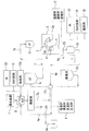
- the beverage supply system piping 7 of this beverage filling device is provided with a balance tank 5 and a heat sterilization section (in order from the upstream side to the downstream side as viewed from the flow of the beverage in the pipeline from the blending device 1 to the filling machine 2.
- UHT heat sterilization section
- manifold valve 13 aseptic surge tank 19
- head tank 11 head tank 11.
- a drain pipe 6 c branches from the upstream return path 6 a via a valve 24.
- a water supply source 23 and an alkaline cleaning liquid supply source 15 are connected to the balance tank 5 via supply pipes in order to perform purification and sterilization.
- Various instruments 8 for measuring and detecting the temperature, concentration, flow rate, pressure and others of the alkaline cleaning liquid supplied from the alkaline cleaning liquid supply source 15 and flowing in the upstream circulation path are attached to the upstream return path 6a. .
- the supply source 15a of the acidic cleaning liquid is also connected to the balance tank 5 as necessary.
- the alkaline cleaning liquid sent from the alkaline cleaning liquid supply source 15 contains a desired one of chlorinated alkalis such as sodium hydroxide, potassium hydroxide and sodium hypochlorite as alkaline components.
- alkaline cleaning liquids are composed of hydroxycarboxylic acids such as organic acids such as citric acid, succinic acid and gluconic acid, or phosphoric acid and alkanolamine salts such as alkali metal salts, alkaline earth metal salts, ammonium salts and ethylenediaminetetraacetic acid.
- hydroxycarboxylic acids such as organic acids such as citric acid, succinic acid and gluconic acid, or phosphoric acid and alkanolamine salts such as alkali metal salts, alkaline earth metal salts, ammonium salts and ethylenediaminetetraacetic acid.
- Sequestering agents such as acid compounds, nonionic surfactants such as anionic surfactants, cationic surfactants, polyoxyethylene alkylphenyl ethers, solubilizers such as sodium cumene sulfonate, polyacrylic acid Or an acid polymer such as these, or a metal salt thereof, a corrosion inhibitor, an antiseptic, an antioxidant, a dispersant, an antifoaming agent, or the like. Pure water, ion exchange water, distilled water, tap water, and the like are used as water for dissolving them.
- Various bleaching agents such as hypochlorite, hydrogen peroxide, peracetic acid, sodium percarbonate, thiourea dioxide and the like may also be included.
- a cleaning liquid containing 0.1 to 10% by mass of sodium hydroxide or potassium hydroxide is heated to 50 to 150 ° C. by a heater (not shown) provided at the outlet of the balance tank 5 and supplied to the upstream circuit. If the circulation is performed for 5 to 120 minutes, the inside of the upstream piping part 7a can be appropriately purified, and at the same time, the SIP processing can be completed by sterilizing the upstream piping part 7a.
- Sodium hydroxide or potassium hydroxide added to the alkaline cleaning liquid has a poor purification ability of the deposits in the pipe by the beverage when the concentration is less than 0.2% by mass. If the concentration is higher than 5% by mass, the purification ability and the sterilization ability are poor. It reaches the desired level or higher, and on the contrary, the cost increases.
- the bactericidal property can be improved as compared with the case of using sodium hydroxide. If the chlorine concentration is less than 100 ppm, the bactericidal effect is not remarkable even if sodium hypochlorite is added, and if it exceeds 3,000 ppm, the bactericidal effect becomes more than necessary, which is disadvantageous in terms of cost.
- the circulation temperature of the alkaline cleaning liquid is less than 50 ° C., the purifying property and the sterilizing property are inferior. It is difficult to increase the temperature above 150 ° C., although the purifying property and the sterilizing property are sufficient.
- the alkaline cleaning liquid is circulated for less than 5 minutes, the cleanability is poor, and if it exceeds 120 minutes, the cleanability and sterilization are sufficient, but the productivity is adversely affected.
- the upstream circuit is preferably rinsed with sterile water.
- sterile water may be water that has been treated under the sterilization conditions or more of the beverage to be produced next.
- This sterile water can be produced by heating the UHT 18 while passing water from the water supply source 23.
- the inside of the upstream piping part 7a is purified with this sterile water, and at the same time, the inside of the upstream piping part 7a is warmed to a temperature suitable for the next beverage filling by heat transfer from the sterile water. This makes it possible to quickly start the filling operation.
- the filling machine 2 passes from the manifold valve 13 on the downstream side of the upstream pipe portion 7 a through the aseptic surge tank 19 and the head tank 11.
- the downstream return path 6b With respect to the downstream piping part 7b leading to the inside, a downstream circulation path for purification and sterilization is formed.
- the downstream return path 6b includes CIP cups 9 that can be brought into contact with and separated from the openings of the filling nozzles 2a of the filling machine 2 on the start end side.
- each CIP cup 9 is covered with an opening at the tip of the filling nozzle 2a of the filling machine 2 by an actuator (not shown), so that the start end of the downstream return path 6b is connected to the opening of the filling nozzle 2a.
- Each CIP cup 9 is connected to a manifold (not shown).
- the downstream end of the return path 6b reaches the manifold valve 13 through the balance tank 10.
- a sterile water storage tank 20 is connected to the manifold valve 13 via a supply pipe, and a water supply source 12 and an alkaline cleaning liquid supply source 14 are connected to the balance tank 10. Each is connected via a supply pipe.
- the drain pipe 6d branches from the pipe from the steam CIP cup 9 to the balance tank 10 in the downstream return path 6b via the valve 25.
- the supply source 16 of the acidic cleaning liquid is also connected to the balance tank 10 as necessary. If purification is insufficient with only the alkaline cleaning liquid, the acidic cleaning liquid may be circulated before the alkaline cleaning liquid is circulated.
- the water supply source 12, the alkaline cleaning liquid supply source 14, and the acidic cleaning liquid supply source 16 are a water supply source 23, an alkaline cleaning liquid supply source 15, and an acidic cleaning liquid supply source 15a connected to the upstream balance tank 5, respectively. It may be integrated.
- Various instruments 17 for measuring and detecting the temperature, concentration, flow rate, pressure gauge and others of the alkaline cleaning liquid supplied from the alkaline cleaning liquid supply source 14 to the upstream circulation path are attached to the upstream return path 6b.
- the alkaline cleaning liquid sent from the alkaline cleaning liquid supply source 14 can be a cleaning liquid having the same components as the alkaline cleaning liquid sent from the alkaline cleaning liquid supply source 15 in the upstream pipe section 7a.
- the purification and sterilization in the downstream side piping part 7b can be performed by making the temperature and circulation time at the time of circulation the same as the above.
- the purification ability may be enhanced by bubbling carbon dioxide, nitrogen, air, or other gas in the alkaline cleaning liquid.
- the downstream circuit is preferably rinsed with sterile water.
- This sterile water is stored in the sterile water storage tank 20.
- the aseptic water in the storage tank 20 is supplied after being heated by a heater (not shown) provided at the outlet of the balance tank 10.
- the inside of the downstream side piping part 7b is purified with this sterile water, and at the same time, the inside of the downstream side piping part 7b is warmed to a temperature suitable for the next beverage filling by heat transfer from the sterile water. This makes it possible to quickly start the filling operation.
- the purification equipment is provided with various switching valves, a pump, and the like, which are controlled by a predetermined control device (not shown) such as a sequence control device (not shown).
- a predetermined control device such as a sequence control device (not shown).
- the alkaline cleaning liquid is sent to the upstream circulation path and the downstream circulation path from the respective alkaline cleaning liquid supply sources 15 and 14, and the inside of the upstream piping section 7a and the filling machine 2 are circulated by the circulation of the alkaline cleaning liquid.
- the inside of the downstream piping part 7b including the inner filling nozzle 2a is purified.
- the alkaline cleaning liquid used for cleaning the upstream side piping part 7a and the downstream side piping part 7b and circulating in each circulation path is switched by switching the valves 24 and 25 after a predetermined cleaning time has passed. It is discharged from the drain pipes 6c and 6d to the outside.
- an alkaline cleaning solution containing 0.1 to 10% by mass of sodium hydroxide or potassium hydroxide is used, it is heated to 50 to 150 ° C. by a heater (not shown) provided at the outlet of the balance tanks 5 and 10. In addition, it is supplied to the upstream circulation path and the downstream circulation path, respectively. When this circulation is performed for 5 to 120 minutes, the inside of the upstream side piping section 7a and the inside of the downstream side circulation path 7b are appropriately purified. At the same time, the inside of the upstream side piping part 7a and the inside of the downstream side piping part 7b are sterilized, and the SIP process is simultaneously performed without separately performing the conventional SIP process.
- this cleaning solution When this cleaning solution is used, it is heated to 50 to 150 ° C., then supplied to the upstream circulation path and the downstream circulation path, and circulated for 5 to 120 minutes to circulate in the upstream piping section 7a and the downstream piping section 7b.
- the inside can be properly purified and sterilized at the same time, and therefore the conventional SIP process can be omitted.
- the acidic cleaning liquid is supplied from the acidic cleaning liquid supply sources 15a and 16 to the upstream circulation path and the downstream circulation path, and cleaning with the acidic cleaning liquid is performed.
- the upstream circulation path and the downstream circulation path are rinsed with water or sterile water. It is desirable that the water used for the rinsing has been treated with a sterilizing effect that is greater than or equal to the sterilizing effect that is acceptable for the beverage to be supplied next time.
- Sterile water used for rinsing in the upstream circulation path is made by heating while passing water from the water supply source 23 through the UHT 18. That is, it is possible to circulate while making aseptic water.
- sterile water used for rinsing in the downstream circulation path one stored in advance in a sterile water storage tank 20 is used.
- liquid may be fed from the UHT 18 into the downstream circuit and the line after the aseptic surge tank 19 may be rinsed.
- the aseptic water in the storage tank 20 is sterilized by heat sterilization, filtration sterilization, or the like.
- the inside of the downstream piping part 7b is rinsed with this sterile water, and at the same time, the inside of the downstream piping part 7b is cooled to a temperature suitable for the next beverage filling by heat transfer from the sterile water.
- aseptic aseptic air is introduced into each of the aseptic surge tanks 19 and 11, and the residual water in each of the aseptic surge tanks 19 and 11 and piping is drained.
- the present invention is configured as described above, but is not limited to the above-described embodiment, and various modifications can be made within the scope of the gist of the present invention.
- Both the balance tanks 10 and 5 are connected or integrated, and the UHT 18, the ACTs 19 and 11, and the filling machine 2 are all integrated pipes, and purification and sterilization can be performed simultaneously.
- the container is not limited to a bottle but may be a paper container.
- the heat sterilization unit UHT
- it is also possible to employ one using other sterilization methods such as an ultraviolet sterilization unit, a high-pressure sterilization unit, and a filtration sterilization unit.
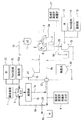
- a beverage filling device After filling a sterilized beverage into a 500 mL capacity PET bottle sterilized in an aseptic atmosphere and sealing with a sterilized cap, a beverage filling device of 600 bpm (bottle per minute) is filled with milked sweetened tea beverage for 20 hours. 2, an alkaline cleaning solution of 4% by mass of sodium hydroxide was prepared in the balance tank 5 indicated by a thick line, and the inside of the thick line path was circulated for 30 minutes at a temperature of 85 ° C.
- an alkaline cleaning solution of 4% by mass of sodium hydroxide was prepared in a balance tank 10 indicated by a thick line and circulated in the thick line path at a temperature of 85 ° C. for 30 minutes.
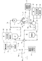
- the green tea beverage After filling the sterilized beverage in a 500 ml capacity PET bottle sterilized in an aseptic atmosphere and sealing it with a sterilized cap, the green tea beverage is filled for 20 hours, and then the thick line balance tank 5 in FIG. A 2% by mass sodium hydroxide alkaline cleaning solution was prepared and circulated in the thick line path at a temperature of 85 ° C. for 20 minutes.
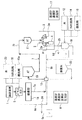
- an alkaline cleaning solution containing 2% by mass of sodium hydroxide was prepared in the balance tank 10 of FIG. 3 and circulated in the thick line path at a temperature of 85 ° C. for 20 minutes. Then, normal temperature sterile water was transferred from the sterile water tank 20 to the balance tank 5 and rinsed according to the thick line route of FIG. 4, and then barley tea beverage was continuously filled in each PET bottle for 15 hours. There was no decay in any of the PET bottle fillings.
- a balance tank indicated by a thick line in FIG. 5 an alkaline cleaning liquid containing 0.5% by mass of potassium hydroxide and 600 ppm of sodium hypochlorite was prepared and circulated in the thick line path at a temperature of 75 ° C. for 20 minutes. Further, an alkaline cleaning liquid containing 0.5% by mass of potassium hydroxide and 600 ppm of sodium hypochlorite having a chlorine concentration of 600 ppm was prepared in the balance tank 10 of FIG.
- the beverage supply system piping 7 of this beverage filling device is balanced in order from the upstream side to the downstream side as seen from the flow of the beverage in the pipeline from the preparation device 1 to the filling machine 2.
- a tank 5, a sterilization unit (UHT) 18, and a head tank 11 are provided, and the head tank 11 reaches the filling machine 2.
- a water supply source 23 and an alkaline cleaning liquid supply source 15 are connected to the balance tank 5 via supply pipes for purification and sterilization. If necessary, an acidic cleaning liquid supply source 15 a is also connected to the balance tank 5.
- the alkaline cleaning liquid sent from the alkaline cleaning liquid supply source 15 may have the same composition as that in the first embodiment.
- a return path 7c is provided substantially in parallel with the beverage supply system pipe 7.
- the return path 7 c includes cups 9 that can be brought into contact with and separated from the openings of the filling nozzles 2 a of the filling machine 2 on the start end side.
- each cup 9 is covered with the opening of the tip of the filling nozzle 2a of the filling machine 2 by an actuator (not shown), so that the starting end of the return path 7c is connected to the opening of the filling nozzle 2a.
- the return path 7 c extends from each cup 9 to a manifold (not shown), and reaches the balance tank 5 via the balance tank 10.
- a drain pipe 7d is connected to the return path 7c through a valve 26. After being supplied from the alkaline cleaning liquid supply source 15, the drain pipe 7d measures and detects the temperature, concentration, flow rate, pressure, and the like of the alkaline cleaning liquid that circulates the circulation path through the balance tank 5, the sterilization unit 18, and the like. Various instruments 17 are attached.
- the inside of the circulation path is rinsed with water.
- the water used for this rinsing can be made by heating while passing water from the water supply source 23 through the sterilizing section 18 such as UHT.
- this water has been treated with a sterilizing effect that is higher than the sterilizing effect that is acceptable for the beverage that is to be supplied into the beverage supply system pipe 7 next time.
- the inside of the beverage supply system pipe 7 is rinsed and purified with this water, and at the same time, the inside of the beverage supply system pipe 7 is cooled to a temperature suitable for filling the next beverage by heat transfer to the water. This makes it possible to quickly start the filling operation.
- the alkaline cleaning liquid is sent from each alkaline cleaning liquid supply source 15 to the beverage supply system piping 7 and circulates in the circulation path for a predetermined time.
- the inside of the beverage supply system pipe 7 from the balance tank 5 to the filling nozzle 2a in the filling machine 2 is purified and sterilized at the same time.
- the alkaline cleaning liquid sent into the beverage supply system pipe 7 circulates in the circulation path for a predetermined time, and is then discharged to the outside as a waste liquid from the drain pipe 7d.
- the inside of the beverage supply system pipe 7 can be appropriately purified by heating it to 50 to 150 ° C. and then supplying it to the beverage supply system pipe 7 and supplying it for 5 to 120 minutes. It can be sterilized at the same time, and thus the conventional SIP process can be omitted.
- the acidic cleaning liquid is supplied into the circulation path from the acidic cleaning liquid supply source 15a as needed, and the beverage supply system pipe 7 is cleaned with the acidic cleaning liquid.
- the water used for rinsing in the beverage supply system pipe 7 is produced by heating while passing water from the water supply source 23 through the sterilization unit 18 which is UHT, for example.
- This rinsing water is desirably treated with a sterilizing effect that is greater than or equal to the sterilizing effect that is acceptable for the beverage to be supplied into the beverage supply system pipe 7 next time.
- valve 26 is closed, and the cup 9 is removed from the opening of each filling nozzle 2a by an actuator (not shown).
- the present invention is not limited to a beverage filling method and apparatus in an aseptic filling line, and is applicable to all manufacturing facilities that require a product liquid line to be sterilized before manufacturing a beverage packaging body such as a hot pack line or a chilled beverage line. Applicable.
Abstract
Description
以下に、本発明の実施の形態1について図面を参照して説明する。
上流側配管部7a内と下流側配管部7b内の洗浄に使用され、各循環路内を巡ったアルカリ性洗浄液は、所定の洗浄時間が経過した後にバルブ24,25が各々切り替えられことにより、各ドレン管6c,6dから外部に排出される。
このすすぎに用いられる水は、次回供給する予定の飲料について容認される殺菌効果以上の殺菌効果で処理されたものであるのが望ましい。
図5に示すように、この飲料充填装置の飲料供給系配管7は、その調合装置1から充填機2に至る管路中に、飲料の流れから見て上流側から下流側へと順に、バランスタンク5、殺菌部(UHT)18、ヘッドタンク11を有し、ヘッドタンク11から充填機2内に至っている。
(6)次回の飲料の充填作業が開始され、図7中、太線で示したごとく調合装置1で新たに調合された飲料が浄化された飲料供給系配管7を通って充填機2内に至り、充填機2の充填ノズル2aから容器であるボトル4に充填される。
6a…上流側帰還路
6b…下流側帰還路
7…飲料供給系配管
7a…上流側配管部
7b…下流側配管部
18…殺菌部
Claims (8)
- 飲料を殺菌部から充填機内へと送る飲料供給系配管にアルカリ性洗浄液を流すことにより、今回の飲料の供給に使用した飲料供給系配管の浄化と殺菌を同時に行い、次回供給する予定の飲料について容認される殺菌効果以上の殺菌効果で処理された水により上記飲料供給系配管内をリンスし、しかる後に上記次回の飲料の供給を開始することを特徴とする飲料の充填方法。
- 飲料を加熱殺菌部から充填機内へと送る飲料供給系配管について殺菌した後、上記飲料を上記飲料供給系配管から殺菌済の容器に充填し、容器を密封する飲料の充填方法において、上記飲料供給系配管のうち上記殺菌部を経由する上流側配管部に対し上流側帰還路を設けて上流側循環路を形成し、上記飲料供給系配管のうち上記上流側配管部より下流側から上記充填機内に至る下流側配管部に対し下流側帰還路を設けて下流側循環路を形成し、アルカリ性洗浄液を上記上流側循環路内及び上記下流側循環路内の各々で循環させることによって、上記飲料供給系配管内の浄化及び殺菌を行い、次いで水リンスを行った後に上記飲料の充填を開始することを特徴とする飲料の充填方法。
- 請求項1又は請求項2に記載の飲料の充填方法において、リンスで使用する水の温度を、充填する飲料と同等の温度にすることを特徴とする飲料の充填方法。
- 請求項1乃至請求項3のいずれかに記載の飲料の充填方法において、アルカリ性洗浄液は少なくとも水酸化ナトリウム又は水酸化カリウムを0.1~10質量%含んだ洗浄液とすることを特徴とする飲料の充填方法。
- 請求項1乃至請求項4のいずれかに記載の飲料の充填方法において、アルカリ性洗浄液は少なくとも塩素濃度が100~3,000ppmの次亜塩素酸ナトリウムを含んだ洗浄液とすることを特徴とする飲料の充填方法。
- 請求項1乃至請求項5のいずれかに記載の飲料の充填方法において、アルカリ性洗浄液を50~150℃に加熱して供給することを特徴とする飲料の充填方法。
- 請求項1乃至請求項6のいずれかに記載の飲料の充填方法において、アルカリ性洗浄液の循環を5~120分行うことを特徴とする飲料の充填方法。
- 請求項1乃至請求項7のいずれかに記載の飲料の充填方法において、アルカリ性洗浄液に漂白剤を添加して供給することを特徴とする飲料の充填方法。
Priority Applications (5)
| Application Number | Priority Date | Filing Date | Title |
|---|---|---|---|
| EP13864264.0A EP2937309B1 (en) | 2012-12-21 | 2013-12-17 | Beverage filling method |
| CN201380056133.4A CN104755411B (zh) | 2012-12-21 | 2013-12-17 | 饮料的灌装方法 |
| EP16184788.4A EP3120940B1 (en) | 2012-12-21 | 2013-12-17 | Beverage filling method |
| JP2014553144A JP6222110B2 (ja) | 2012-12-21 | 2013-12-17 | 飲料の充填方法 |
| US14/650,737 US10442669B2 (en) | 2012-12-21 | 2013-12-17 | Drink filling method |
Applications Claiming Priority (2)
| Application Number | Priority Date | Filing Date | Title |
|---|---|---|---|
| JP2012280093 | 2012-12-21 | ||
| JP2012-280093 | 2012-12-21 |
Publications (1)
| Publication Number | Publication Date |
|---|---|
| WO2014098058A1 true WO2014098058A1 (ja) | 2014-06-26 |
Family
ID=50978385
Family Applications (1)
| Application Number | Title | Priority Date | Filing Date |
|---|---|---|---|
| PCT/JP2013/083692 WO2014098058A1 (ja) | 2012-12-21 | 2013-12-17 | 飲料の充填方法 |
Country Status (5)
| Country | Link |
|---|---|
| US (1) | US10442669B2 (ja) |
| EP (2) | EP3120940B1 (ja) |
| JP (2) | JP6222110B2 (ja) |
| CN (3) | CN104755411B (ja) |
| WO (1) | WO2014098058A1 (ja) |
Cited By (30)
| Publication number | Priority date | Publication date | Assignee | Title |
|---|---|---|---|---|
| JP6056930B1 (ja) * | 2015-09-17 | 2017-01-11 | 大日本印刷株式会社 | 無菌充填装置及びその浄化方法 |
| WO2017047691A1 (ja) * | 2015-09-17 | 2017-03-23 | 大日本印刷株式会社 | 無菌充填装置及びその浄化方法 |
| JP2017071448A (ja) * | 2016-12-08 | 2017-04-13 | 大日本印刷株式会社 | 無菌充填装置及びその浄化方法 |
| JP2017095114A (ja) * | 2015-11-18 | 2017-06-01 | 大日本印刷株式会社 | 無菌充填装置及びその浄化方法 |
| JP2017095115A (ja) * | 2015-11-18 | 2017-06-01 | 大日本印刷株式会社 | 無菌充填装置及びその浄化方法 |
| WO2017111047A1 (ja) * | 2015-12-22 | 2017-06-29 | 大日本印刷株式会社 | 殺菌処理の移行方法および製品充填装置並びに製品充填装置の洗浄・殺菌方法及び装置 |
| JP2017114569A (ja) * | 2016-12-28 | 2017-06-29 | 大日本印刷株式会社 | 殺菌処理の移行方法および製品充填装置 |
| JP2017128395A (ja) * | 2017-04-20 | 2017-07-27 | 大日本印刷株式会社 | 無菌充填装置及びその浄化方法 |
| JP2017140578A (ja) * | 2016-02-10 | 2017-08-17 | 朝日化学工業株式会社 | 焦げ付き汚れの除去洗浄方法および焦げ付き汚れの洗浄用混合液 |
| JP2017165488A (ja) * | 2017-04-20 | 2017-09-21 | 大日本印刷株式会社 | 無菌充填装置及びその浄化方法 |
| JP6233940B1 (ja) * | 2017-01-20 | 2017-11-22 | 株式会社日本キャンパック | Cip洗浄方法 |
| CN107758017A (zh) * | 2016-08-18 | 2018-03-06 | 北冰洋(北京)饮料食品有限公司 | 具有水循环利用功能的饮料生产线 |
| CN107854706A (zh) * | 2017-06-30 | 2018-03-30 | 沪东中华造船(集团)有限公司 | 一种用于不锈钢化学品船饮水舱消毒清洗的方法 |
| JP2018058641A (ja) * | 2016-04-07 | 2018-04-12 | 大日本印刷株式会社 | 飲料充填装置の洗浄・殺菌方法及び装置 |
| WO2019009169A1 (ja) * | 2017-07-04 | 2019-01-10 | 大日本印刷株式会社 | 無菌充填システム |
| WO2019069967A1 (ja) * | 2017-10-04 | 2019-04-11 | 大日本印刷株式会社 | 飲料充填装置の洗浄・殺菌方法 |
| JP2019123526A (ja) * | 2018-01-16 | 2019-07-25 | 大日本印刷株式会社 | 飲料充填装置の洗浄・殺菌方法 |
| WO2019189683A1 (ja) * | 2018-03-29 | 2019-10-03 | 大日本印刷株式会社 | 脱臭方法 |
| JP2019172358A (ja) * | 2018-03-29 | 2019-10-10 | 大日本印刷株式会社 | 脱臭方法 |
| JP2019172357A (ja) * | 2018-03-29 | 2019-10-10 | 大日本印刷株式会社 | 脱臭方法 |
| JP2019182453A (ja) * | 2018-04-05 | 2019-10-24 | 三菱重工機械システム株式会社 | 充填システム |
| JP2020073402A (ja) * | 2019-11-13 | 2020-05-14 | 大日本印刷株式会社 | 飲料充填装置及び飲料充填装置の洗浄・殺菌方法 |
| JP2021014314A (ja) * | 2020-11-18 | 2021-02-12 | 大日本印刷株式会社 | 脱臭方法 |
| JP2021014315A (ja) * | 2020-11-18 | 2021-02-12 | 大日本印刷株式会社 | 脱臭方法 |
| JP2021014313A (ja) * | 2020-11-18 | 2021-02-12 | 大日本印刷株式会社 | 脱臭方法 |
| JP2021035867A (ja) * | 2020-11-18 | 2021-03-04 | 大日本印刷株式会社 | 脱臭方法 |
| US11046567B2 (en) * | 2017-02-02 | 2021-06-29 | Dai Nippon Printing Co., Ltd. | Beverage aseptic filling system and carbonated beverage aseptic filling system |
| JP2021525102A (ja) * | 2018-05-21 | 2021-09-24 | 江蘇新美星包装機械股▲フェン▼有限公司 | 顆粒入り液体飲料の調製殺菌装置及び調製方法 |
| WO2021230342A1 (ja) * | 2020-05-15 | 2021-11-18 | 大日本印刷株式会社 | 無菌充填機の洗浄・殺菌方法及び無菌充填機 |
| WO2022138611A1 (ja) | 2020-12-25 | 2022-06-30 | 大日本印刷株式会社 | 飲料充填システム及びcip処理方法 |
Families Citing this family (20)
| Publication number | Priority date | Publication date | Assignee | Title |
|---|---|---|---|---|
| BR112017001663A2 (pt) | 2014-08-15 | 2018-01-30 | Ecolab Usa Inc | métodos para monitorar um processo de limpeza no local e para gerar e usar uma biblioteca de limpeza no local, e, sistema de limpeza no local. |
| CN106575426B (zh) * | 2014-08-15 | 2020-06-09 | 艺康美国股份有限公司 | Cip洗涤比较和模拟 |
| CN105360850B (zh) * | 2015-10-14 | 2017-03-08 | 湖北康乐滋食品饮料有限公司 | 坚果饮料生产线及生产方法 |
| JP7149685B2 (ja) * | 2016-01-18 | 2022-10-07 | ザ コカ・コーラ カンパニー | 飲料充填装置及び容器入り飲料の製造方法 |
| DE102016107355A1 (de) * | 2016-04-20 | 2017-10-26 | Krones Ag | Vorrichtung zum Befüllen mindestens eines Behälters mit einem Füllprodukt in einer Getränkeabfüllanlage |
| WO2018151308A1 (ja) | 2017-02-20 | 2018-08-23 | 大日本印刷株式会社 | 殺菌剤ガス化装置及び殺菌剤ガス化装置の洗浄方法 |
| WO2018181226A1 (ja) | 2017-03-27 | 2018-10-04 | 三菱ケミカル株式会社 | 触媒及び触媒群 |
| JP6439949B2 (ja) * | 2017-04-27 | 2018-12-19 | 大日本印刷株式会社 | 無菌充填装置及びその浄化方法 |
| US11498823B2 (en) | 2018-06-21 | 2022-11-15 | Dai Nippon Printing Co., Ltd. | Carbonated beverage aseptic filling system, beverage filling system, and CIP processing method |
| JP6760343B2 (ja) * | 2018-08-31 | 2020-09-23 | 大日本印刷株式会社 | 無菌充填機及びその浄化方法 |
| CN109091691A (zh) * | 2018-10-23 | 2018-12-28 | 广州达意隆包装机械股份有限公司 | 一种灌装机的管路杀菌系统及方法 |
| CN109332290B (zh) * | 2018-11-02 | 2023-08-04 | 江苏新美星包装机械股份有限公司 | 一种物料杀菌机 |
| JP6725196B1 (ja) * | 2019-02-15 | 2020-07-15 | 株式会社日本キャンパック | Cip洗浄方法 |
| JP6761606B2 (ja) * | 2019-03-18 | 2020-09-30 | 大日本印刷株式会社 | 飲料処理システム |
| CN114206768A (zh) * | 2019-06-07 | 2022-03-18 | 三得利控股株式会社 | 饮料供给系统的清洗装置以及饮料供给系统的清洗方法 |
| JP6897716B2 (ja) * | 2019-06-14 | 2021-07-07 | 大日本印刷株式会社 | 無菌充填機の充填バルブの冷却方法 |
| DE102019132749A1 (de) * | 2019-12-03 | 2021-06-10 | Krones Ag | Vorrichtung zum Befüllen eines Behälters mit CIP-Reinigung |
| CN112275697A (zh) * | 2020-09-16 | 2021-01-29 | 东鹏饮料(集团)股份有限公司 | 一种延长设备工作时长的清洗方法 |
| JP7157936B2 (ja) * | 2021-03-03 | 2022-10-21 | 大日本印刷株式会社 | 飲料充填システム及びcip処理方法 |
| DE102021128705A1 (de) * | 2021-11-04 | 2023-05-04 | Krones Aktiengesellschaft | CIP-Behandlung einer Vorrichtung zum Befüllen von Behältern mit einem Füllprodukt |
Citations (9)
| Publication number | Priority date | Publication date | Assignee | Title |
|---|---|---|---|---|
| JPH06264097A (ja) * | 1993-01-26 | 1994-09-20 | T Paul Kk | アルカリ性殺菌洗浄剤 |
| JP2000153245A (ja) | 1998-11-20 | 2000-06-06 | Sanyo Coca Cola Bottling Kk | 飲料等の製造ラインの洗浄方法および洗浄装置 |
| JP2002205067A (ja) * | 2001-01-12 | 2002-07-23 | Hoshizaki Electric Co Ltd | 殺菌能を有する洗浄水およびその製造方法 |
| JP2004066159A (ja) * | 2002-08-08 | 2004-03-04 | Daisan Kogyo Kk | 食品製造設備における被洗浄物の殺菌洗浄方法 |
| JP2007002014A (ja) * | 2005-06-21 | 2007-01-11 | Kao Corp | 水性液体洗浄剤組成物 |
| JP2007022600A (ja) | 2005-07-19 | 2007-02-01 | Toyo Seikan Kaisha Ltd | 食品充填システムにおける充填機の配管系洗浄殺菌方法 |
| JP2007331801A (ja) | 2006-06-15 | 2007-12-27 | Nippon Canpack:Kk | 飲料充填装置の清浄装置 |
| JP2011255938A (ja) * | 2010-06-10 | 2011-12-22 | Dainippon Printing Co Ltd | 無菌充填方法及び装置 |
| US20120000492A1 (en) | 2009-07-24 | 2012-01-05 | Khs Gmbh | System for treating and/or processing liquid products and method for cleaning components of such systems |
Family Cites Families (14)
| Publication number | Priority date | Publication date | Assignee | Title |
|---|---|---|---|---|
| SE356683B (ja) | 1969-12-30 | 1973-06-04 | Tetra Pak Int | |
| JPS528036B2 (ja) | 1973-08-11 | 1977-03-05 | ||
| US4878951A (en) * | 1989-01-17 | 1989-11-07 | A & L Laboratories, Inc. | Low-foaming alkaline, hypochlorite cleaner |
| JPH06220496A (ja) | 1993-01-26 | 1994-08-09 | T Paul Kk | 液体殺菌洗浄剤 |
| SE527439C2 (sv) | 2004-04-22 | 2006-03-07 | Tetra Laval Holdings & Finance | Metod att diska en livsmedelsanläggning |
| FI20045350A (fi) | 2004-09-22 | 2006-03-23 | Tampereen Teollisuussaehkoe Oy | Menetelmä prosessilaitteiston pesemiseksi |
| CN2931453Y (zh) * | 2005-08-17 | 2007-08-08 | 上海瑞勇实业有限公司 | 一种多功能小型化制水、灌装一体机 |
| JP4919388B2 (ja) | 2006-03-09 | 2012-04-18 | 国立大学法人広島大学 | 食品製造設備の被洗浄物を洗浄する洗浄装置、および洗浄方法 |
| DE102006060204A1 (de) * | 2006-12-18 | 2008-06-19 | Krones Ag | Verfahren zur Reinigung einer Anlage |
| JP4940944B2 (ja) * | 2006-12-28 | 2012-05-30 | 澁谷工業株式会社 | 容器充填システム |
| DE102009039180A1 (de) * | 2009-08-28 | 2011-03-03 | Krones Ag | Vorrichtung und Verfahren zum Bereitstellen einer sterilen Flüssigkeit für eine Abfüllanlage |
| US20120000049A1 (en) * | 2010-06-30 | 2012-01-05 | Reginald Wallace | Oil Filter Particle Entrapping Method |
| CN202107514U (zh) * | 2011-03-29 | 2012-01-11 | 张敦杰 | 啤酒灌装装置的清洗及杀菌系统 |
| WO2013113793A1 (en) | 2012-02-03 | 2013-08-08 | Tetra Laval Holdings & Finance S.A. | A liquid processing system with secondary sub-systems for reducing product losses and water consumption |
-
2013
- 2013-12-17 JP JP2014553144A patent/JP6222110B2/ja active Active
- 2013-12-17 CN CN201380056133.4A patent/CN104755411B/zh active Active
- 2013-12-17 CN CN201610881559.9A patent/CN106938836B/zh active Active
- 2013-12-17 US US14/650,737 patent/US10442669B2/en active Active
- 2013-12-17 EP EP16184788.4A patent/EP3120940B1/en active Active
- 2013-12-17 WO PCT/JP2013/083692 patent/WO2014098058A1/ja active Application Filing
- 2013-12-17 EP EP13864264.0A patent/EP2937309B1/en active Active
- 2013-12-17 CN CN201610881558.4A patent/CN106976834A/zh active Pending
-
2017
- 2017-08-23 JP JP2017160454A patent/JP6460181B2/ja active Active
Patent Citations (9)
| Publication number | Priority date | Publication date | Assignee | Title |
|---|---|---|---|---|
| JPH06264097A (ja) * | 1993-01-26 | 1994-09-20 | T Paul Kk | アルカリ性殺菌洗浄剤 |
| JP2000153245A (ja) | 1998-11-20 | 2000-06-06 | Sanyo Coca Cola Bottling Kk | 飲料等の製造ラインの洗浄方法および洗浄装置 |
| JP2002205067A (ja) * | 2001-01-12 | 2002-07-23 | Hoshizaki Electric Co Ltd | 殺菌能を有する洗浄水およびその製造方法 |
| JP2004066159A (ja) * | 2002-08-08 | 2004-03-04 | Daisan Kogyo Kk | 食品製造設備における被洗浄物の殺菌洗浄方法 |
| JP2007002014A (ja) * | 2005-06-21 | 2007-01-11 | Kao Corp | 水性液体洗浄剤組成物 |
| JP2007022600A (ja) | 2005-07-19 | 2007-02-01 | Toyo Seikan Kaisha Ltd | 食品充填システムにおける充填機の配管系洗浄殺菌方法 |
| JP2007331801A (ja) | 2006-06-15 | 2007-12-27 | Nippon Canpack:Kk | 飲料充填装置の清浄装置 |
| US20120000492A1 (en) | 2009-07-24 | 2012-01-05 | Khs Gmbh | System for treating and/or processing liquid products and method for cleaning components of such systems |
| JP2011255938A (ja) * | 2010-06-10 | 2011-12-22 | Dainippon Printing Co Ltd | 無菌充填方法及び装置 |
Non-Patent Citations (2)
| Title |
|---|
| ANONYMOUS: "The Orange Book", 1998, TETRA PAK PROCESSING SYSTEMS AB, article "7.9 Cleaning-in-place", pages: I, 127 - 129, XP055829934 |
| See also references of EP2937309A4 |
Cited By (66)
| Publication number | Priority date | Publication date | Assignee | Title |
|---|---|---|---|---|
| US11014797B2 (en) | 2015-09-17 | 2021-05-25 | Dai Nippon Printing Co., Ltd. | Aseptic filling apparatus and method of decontaminating the same |
| JP2017056984A (ja) * | 2015-09-17 | 2017-03-23 | 大日本印刷株式会社 | 無菌充填装置及びその浄化方法 |
| WO2017047691A1 (ja) * | 2015-09-17 | 2017-03-23 | 大日本印刷株式会社 | 無菌充填装置及びその浄化方法 |
| US11780719B2 (en) | 2015-09-17 | 2023-10-10 | Dai Nippon Printing Co., Ltd. | Aseptic filling apparatus and method of decontaminating the same |
| JP6056930B1 (ja) * | 2015-09-17 | 2017-01-11 | 大日本印刷株式会社 | 無菌充填装置及びその浄化方法 |
| CN107922177B (zh) * | 2015-09-17 | 2020-07-07 | 大日本印刷株式会社 | 无菌填充装置及其净化方法 |
| CN107922177A (zh) * | 2015-09-17 | 2018-04-17 | 大日本印刷株式会社 | 无菌填充装置及其净化方法 |
| US11753287B2 (en) | 2015-09-17 | 2023-09-12 | Dai Nippon Printing Co., Ltd. | Aseptic filling apparatus and method of decontaminating the same |
| US11745990B2 (en) | 2015-09-17 | 2023-09-05 | Dai Nippon Printing Co., Ltd. | Aseptic filling apparatus and method of decontaminating the same |
| EP3693331A1 (en) * | 2015-09-17 | 2020-08-12 | Dai Nippon Printing Co., Ltd. | Method of decontaminating an aseptic filling apparatus |
| JP2017095114A (ja) * | 2015-11-18 | 2017-06-01 | 大日本印刷株式会社 | 無菌充填装置及びその浄化方法 |
| JP2017095115A (ja) * | 2015-11-18 | 2017-06-01 | 大日本印刷株式会社 | 無菌充填装置及びその浄化方法 |
| EP3881946A1 (en) * | 2015-12-22 | 2021-09-22 | Dai Nippon Printing Co., Ltd. | Sterilization process transition method, product filling apparatus, and method and apparatus of cleaning and sterilizing the product filling apparatus |
| US11034566B2 (en) | 2015-12-22 | 2021-06-15 | Dai Nippon Printing Co., Ltd. | Sterilization process transition method, product filling apparatus, and method and apparatus of cleaning and sterilizing the product filling apparatus |
| EP4129505A1 (en) * | 2015-12-22 | 2023-02-08 | Dai Nippon Printing Co., Ltd. | Method cleaning and sterilizing a product filling apparatus |
| WO2017111047A1 (ja) * | 2015-12-22 | 2017-06-29 | 大日本印刷株式会社 | 殺菌処理の移行方法および製品充填装置並びに製品充填装置の洗浄・殺菌方法及び装置 |
| CN108290729A (zh) * | 2015-12-22 | 2018-07-17 | 大日本印刷株式会社 | 杀菌处理的转换方法及产品充填装置以及产品充填装置的洗净杀菌方法及装置 |
| US10618789B2 (en) | 2015-12-22 | 2020-04-14 | Dai Nippon Printing Co., Ltd. | Sterilization process transition method, product filling apparatus, and method and apparatus of cleaning and sterilizing the product filling apparatus |
| JP2017140578A (ja) * | 2016-02-10 | 2017-08-17 | 朝日化学工業株式会社 | 焦げ付き汚れの除去洗浄方法および焦げ付き汚れの洗浄用混合液 |
| JP2020023371A (ja) * | 2016-04-07 | 2020-02-13 | 大日本印刷株式会社 | 飲料充填装置の洗浄・殺菌方法及び装置 |
| JP2019147625A (ja) * | 2016-04-07 | 2019-09-05 | 大日本印刷株式会社 | 飲料充填装置の洗浄・殺菌方法及び装置 |
| JP2022092058A (ja) * | 2016-04-07 | 2022-06-21 | 大日本印刷株式会社 | 飲料充填装置の洗浄・殺菌方法及び装置 |
| JP7116036B2 (ja) | 2016-04-07 | 2022-08-09 | 大日本印刷株式会社 | 飲料充填装置の洗浄・殺菌方法及び装置 |
| JP2019147624A (ja) * | 2016-04-07 | 2019-09-05 | 大日本印刷株式会社 | 飲料充填装置の洗浄・殺菌方法及び装置 |
| JP2019147628A (ja) * | 2016-04-07 | 2019-09-05 | 大日本印刷株式会社 | 飲料充填装置の洗浄・殺菌方法及び装置 |
| JP2019147626A (ja) * | 2016-04-07 | 2019-09-05 | 大日本印刷株式会社 | 飲料充填装置の洗浄・殺菌方法及び装置 |
| JP2018058641A (ja) * | 2016-04-07 | 2018-04-12 | 大日本印刷株式会社 | 飲料充填装置の洗浄・殺菌方法及び装置 |
| JP2021080028A (ja) * | 2016-04-07 | 2021-05-27 | 大日本印刷株式会社 | 飲料充填装置の洗浄・殺菌方法及び装置 |
| JP2019172377A (ja) * | 2016-04-07 | 2019-10-10 | 大日本印刷株式会社 | 飲料充填装置の洗浄・殺菌方法及び装置 |
| CN107758017A (zh) * | 2016-08-18 | 2018-03-06 | 北冰洋(北京)饮料食品有限公司 | 具有水循环利用功能的饮料生产线 |
| JP2017071448A (ja) * | 2016-12-08 | 2017-04-13 | 大日本印刷株式会社 | 無菌充填装置及びその浄化方法 |
| JP2017114569A (ja) * | 2016-12-28 | 2017-06-29 | 大日本印刷株式会社 | 殺菌処理の移行方法および製品充填装置 |
| JP6233940B1 (ja) * | 2017-01-20 | 2017-11-22 | 株式会社日本キャンパック | Cip洗浄方法 |
| JP2018115299A (ja) * | 2017-01-20 | 2018-07-26 | 株式会社日本キャンパック | Cip洗浄方法 |
| US11046567B2 (en) * | 2017-02-02 | 2021-06-29 | Dai Nippon Printing Co., Ltd. | Beverage aseptic filling system and carbonated beverage aseptic filling system |
| JP2017128395A (ja) * | 2017-04-20 | 2017-07-27 | 大日本印刷株式会社 | 無菌充填装置及びその浄化方法 |
| JP2017165488A (ja) * | 2017-04-20 | 2017-09-21 | 大日本印刷株式会社 | 無菌充填装置及びその浄化方法 |
| CN107854706A (zh) * | 2017-06-30 | 2018-03-30 | 沪东中华造船(集团)有限公司 | 一种用于不锈钢化学品船饮水舱消毒清洗的方法 |
| WO2019009169A1 (ja) * | 2017-07-04 | 2019-01-10 | 大日本印刷株式会社 | 無菌充填システム |
| US11203514B2 (en) | 2017-07-04 | 2021-12-21 | Dai Nippon Printing Co., Ltd. | Aseptic filling system |
| WO2019069967A1 (ja) * | 2017-10-04 | 2019-04-11 | 大日本印刷株式会社 | 飲料充填装置の洗浄・殺菌方法 |
| JP2019064722A (ja) * | 2017-10-04 | 2019-04-25 | 大日本印刷株式会社 | 飲料充填装置の洗浄・殺菌方法 |
| US11708257B2 (en) | 2018-01-16 | 2023-07-25 | Dai Nippon Printing Co., Ltd. | Method of cleaning and sterilizing drink filling apparatus |
| WO2019142742A1 (ja) * | 2018-01-16 | 2019-07-25 | 大日本印刷株式会社 | 飲料充填装置の洗浄・殺菌方法 |
| JP2019123526A (ja) * | 2018-01-16 | 2019-07-25 | 大日本印刷株式会社 | 飲料充填装置の洗浄・殺菌方法 |
| JP2019172357A (ja) * | 2018-03-29 | 2019-10-10 | 大日本印刷株式会社 | 脱臭方法 |
| JP2019172358A (ja) * | 2018-03-29 | 2019-10-10 | 大日本印刷株式会社 | 脱臭方法 |
| WO2019189683A1 (ja) * | 2018-03-29 | 2019-10-03 | 大日本印刷株式会社 | 脱臭方法 |
| EP3778466A4 (en) * | 2018-03-29 | 2021-12-22 | Dai Nippon Printing Co., Ltd. | DEODORIZATION PROCESS |
| JP2019182453A (ja) * | 2018-04-05 | 2019-10-24 | 三菱重工機械システム株式会社 | 充填システム |
| JP6997028B2 (ja) | 2018-04-05 | 2022-01-17 | 三菱重工機械システム株式会社 | 充填システム |
| JP7089116B2 (ja) | 2018-05-21 | 2022-06-21 | 江蘇新美星包装機械股▲フェン▼有限公司 | 顆粒入り液体飲料の調製殺菌装置 |
| JP2021525102A (ja) * | 2018-05-21 | 2021-09-24 | 江蘇新美星包装機械股▲フェン▼有限公司 | 顆粒入り液体飲料の調製殺菌装置及び調製方法 |
| JP2020073402A (ja) * | 2019-11-13 | 2020-05-14 | 大日本印刷株式会社 | 飲料充填装置及び飲料充填装置の洗浄・殺菌方法 |
| JPWO2021230342A1 (ja) * | 2020-05-15 | 2021-11-18 | ||
| JP7070816B2 (ja) | 2020-05-15 | 2022-05-18 | 大日本印刷株式会社 | 無菌充填機の洗浄・殺菌方法及び無菌充填機 |
| WO2021230342A1 (ja) * | 2020-05-15 | 2021-11-18 | 大日本印刷株式会社 | 無菌充填機の洗浄・殺菌方法及び無菌充填機 |
| JP7112682B2 (ja) | 2020-11-18 | 2022-08-04 | 大日本印刷株式会社 | 脱臭方法 |
| JP7104903B2 (ja) | 2020-11-18 | 2022-07-22 | 大日本印刷株式会社 | 脱臭方法 |
| JP7112681B2 (ja) | 2020-11-18 | 2022-08-04 | 大日本印刷株式会社 | 脱臭方法 |
| JP2021035867A (ja) * | 2020-11-18 | 2021-03-04 | 大日本印刷株式会社 | 脱臭方法 |
| JP2021014313A (ja) * | 2020-11-18 | 2021-02-12 | 大日本印刷株式会社 | 脱臭方法 |
| JP2021014315A (ja) * | 2020-11-18 | 2021-02-12 | 大日本印刷株式会社 | 脱臭方法 |
| JP2021014314A (ja) * | 2020-11-18 | 2021-02-12 | 大日本印刷株式会社 | 脱臭方法 |
| JP7047886B2 (ja) | 2020-11-18 | 2022-04-05 | 大日本印刷株式会社 | 脱臭方法 |
| WO2022138611A1 (ja) | 2020-12-25 | 2022-06-30 | 大日本印刷株式会社 | 飲料充填システム及びcip処理方法 |
Also Published As
| Publication number | Publication date |
|---|---|
| EP3120940B1 (en) | 2021-11-17 |
| JP6222110B2 (ja) | 2017-11-01 |
| CN104755411B (zh) | 2016-11-02 |
| JPWO2014098058A1 (ja) | 2017-01-12 |
| EP2937309A4 (en) | 2016-11-02 |
| JP6460181B2 (ja) | 2019-01-30 |
| CN106976834A (zh) | 2017-07-25 |
| EP2937309B1 (en) | 2023-08-02 |
| CN106938836A (zh) | 2017-07-11 |
| EP2937309A1 (en) | 2015-10-28 |
| CN104755411A (zh) | 2015-07-01 |
| CN106938836B (zh) | 2019-11-01 |
| JP2018012548A (ja) | 2018-01-25 |
| US20160185584A1 (en) | 2016-06-30 |
| EP3120940A1 (en) | 2017-01-25 |
| US10442669B2 (en) | 2019-10-15 |
Similar Documents
| Publication | Publication Date | Title |
|---|---|---|
| JP6460181B2 (ja) | 飲料の充填方法 | |
| JP6481839B2 (ja) | 飲料充填装置 | |
| JP5472627B2 (ja) | 無菌充填方法及び装置 | |
| JP7373431B2 (ja) | 飲料充填装置及び飲料充填装置の洗浄・殺菌方法 | |
| JP6801686B2 (ja) | 脱臭方法 | |
| JP2023086834A (ja) | 無菌充填機の洗浄・殺菌方法及び無菌充填機 | |
| JP6761606B2 (ja) | 飲料処理システム | |
| JP7047886B2 (ja) | 脱臭方法 | |
| JP7112682B2 (ja) | 脱臭方法 | |
| JP7307902B2 (ja) | 脱臭方法 | |
| JP7104903B2 (ja) | 脱臭方法 | |
| JP6801685B2 (ja) | 脱臭方法 | |
| JP7112681B2 (ja) | 脱臭方法 | |
| WO2019189683A1 (ja) | 脱臭方法 | |
| WO2021230342A1 (ja) | 無菌充填機の洗浄・殺菌方法及び無菌充填機 | |
| JP2023055367A (ja) | 無菌充填機の無菌水供給配管内の殺菌方法及び殺菌装置 |
Legal Events
| Date | Code | Title | Description |
|---|---|---|---|
| 121 | Ep: the epo has been informed by wipo that ep was designated in this application |
Ref document number: 13864264 Country of ref document: EP Kind code of ref document: A1 |
|
| ENP | Entry into the national phase |
Ref document number: 2014553144 Country of ref document: JP Kind code of ref document: A |
|
| WWE | Wipo information: entry into national phase |
Ref document number: 2013864264 Country of ref document: EP |
|
| WWE | Wipo information: entry into national phase |
Ref document number: 14650737 Country of ref document: US |
|
| NENP | Non-entry into the national phase |
Ref country code: DE |