WO2014034377A1 - 電動車両の強電ハーネス接続構造 - Google Patents
電動車両の強電ハーネス接続構造 Download PDFInfo
- Publication number
- WO2014034377A1 WO2014034377A1 PCT/JP2013/070941 JP2013070941W WO2014034377A1 WO 2014034377 A1 WO2014034377 A1 WO 2014034377A1 JP 2013070941 W JP2013070941 W JP 2013070941W WO 2014034377 A1 WO2014034377 A1 WO 2014034377A1
- Authority
- WO
- WIPO (PCT)
- Prior art keywords
- voltage
- connector terminal
- battery
- vehicle
- harness
- Prior art date
Links
Images


Classifications
-
- B—PERFORMING OPERATIONS; TRANSPORTING
- B60—VEHICLES IN GENERAL
- B60K—ARRANGEMENT OR MOUNTING OF PROPULSION UNITS OR OF TRANSMISSIONS IN VEHICLES; ARRANGEMENT OR MOUNTING OF PLURAL DIVERSE PRIME-MOVERS IN VEHICLES; AUXILIARY DRIVES FOR VEHICLES; INSTRUMENTATION OR DASHBOARDS FOR VEHICLES; ARRANGEMENTS IN CONNECTION WITH COOLING, AIR INTAKE, GAS EXHAUST OR FUEL SUPPLY OF PROPULSION UNITS IN VEHICLES
- B60K1/00—Arrangement or mounting of electrical propulsion units
- B60K1/04—Arrangement or mounting of electrical propulsion units of the electric storage means for propulsion
-
- B—PERFORMING OPERATIONS; TRANSPORTING
- B60—VEHICLES IN GENERAL
- B60K—ARRANGEMENT OR MOUNTING OF PROPULSION UNITS OR OF TRANSMISSIONS IN VEHICLES; ARRANGEMENT OR MOUNTING OF PLURAL DIVERSE PRIME-MOVERS IN VEHICLES; AUXILIARY DRIVES FOR VEHICLES; INSTRUMENTATION OR DASHBOARDS FOR VEHICLES; ARRANGEMENTS IN CONNECTION WITH COOLING, AIR INTAKE, GAS EXHAUST OR FUEL SUPPLY OF PROPULSION UNITS IN VEHICLES
- B60K1/00—Arrangement or mounting of electrical propulsion units
-
- B—PERFORMING OPERATIONS; TRANSPORTING
- B60—VEHICLES IN GENERAL
- B60L—PROPULSION OF ELECTRICALLY-PROPELLED VEHICLES; SUPPLYING ELECTRIC POWER FOR AUXILIARY EQUIPMENT OF ELECTRICALLY-PROPELLED VEHICLES; ELECTRODYNAMIC BRAKE SYSTEMS FOR VEHICLES IN GENERAL; MAGNETIC SUSPENSION OR LEVITATION FOR VEHICLES; MONITORING OPERATING VARIABLES OF ELECTRICALLY-PROPELLED VEHICLES; ELECTRIC SAFETY DEVICES FOR ELECTRICALLY-PROPELLED VEHICLES
- B60L3/00—Electric devices on electrically-propelled vehicles for safety purposes; Monitoring operating variables, e.g. speed, deceleration or energy consumption
- B60L3/0007—Measures or means for preventing or attenuating collisions
-
- B—PERFORMING OPERATIONS; TRANSPORTING
- B60—VEHICLES IN GENERAL
- B60L—PROPULSION OF ELECTRICALLY-PROPELLED VEHICLES; SUPPLYING ELECTRIC POWER FOR AUXILIARY EQUIPMENT OF ELECTRICALLY-PROPELLED VEHICLES; ELECTRODYNAMIC BRAKE SYSTEMS FOR VEHICLES IN GENERAL; MAGNETIC SUSPENSION OR LEVITATION FOR VEHICLES; MONITORING OPERATING VARIABLES OF ELECTRICALLY-PROPELLED VEHICLES; ELECTRIC SAFETY DEVICES FOR ELECTRICALLY-PROPELLED VEHICLES
- B60L50/00—Electric propulsion with power supplied within the vehicle
- B60L50/50—Electric propulsion with power supplied within the vehicle using propulsion power supplied by batteries or fuel cells
- B60L50/60—Electric propulsion with power supplied within the vehicle using propulsion power supplied by batteries or fuel cells using power supplied by batteries
- B60L50/66—Arrangements of batteries
-
- B—PERFORMING OPERATIONS; TRANSPORTING
- B60—VEHICLES IN GENERAL
- B60R—VEHICLES, VEHICLE FITTINGS, OR VEHICLE PARTS, NOT OTHERWISE PROVIDED FOR
- B60R16/00—Electric or fluid circuits specially adapted for vehicles and not otherwise provided for; Arrangement of elements of electric or fluid circuits specially adapted for vehicles and not otherwise provided for
- B60R16/02—Electric or fluid circuits specially adapted for vehicles and not otherwise provided for; Arrangement of elements of electric or fluid circuits specially adapted for vehicles and not otherwise provided for electric constitutive elements
- B60R16/0207—Wire harnesses
- B60R16/0215—Protecting, fastening and routing means therefor
-
- H—ELECTRICITY
- H01—ELECTRIC ELEMENTS
- H01M—PROCESSES OR MEANS, e.g. BATTERIES, FOR THE DIRECT CONVERSION OF CHEMICAL ENERGY INTO ELECTRICAL ENERGY
- H01M50/00—Constructional details or processes of manufacture of the non-active parts of electrochemical cells other than fuel cells, e.g. hybrid cells
- H01M50/20—Mountings; Secondary casings or frames; Racks, modules or packs; Suspension devices; Shock absorbers; Transport or carrying devices; Holders
- H01M50/262—Mountings; Secondary casings or frames; Racks, modules or packs; Suspension devices; Shock absorbers; Transport or carrying devices; Holders with fastening means, e.g. locks
-
- B—PERFORMING OPERATIONS; TRANSPORTING
- B60—VEHICLES IN GENERAL
- B60K—ARRANGEMENT OR MOUNTING OF PROPULSION UNITS OR OF TRANSMISSIONS IN VEHICLES; ARRANGEMENT OR MOUNTING OF PLURAL DIVERSE PRIME-MOVERS IN VEHICLES; AUXILIARY DRIVES FOR VEHICLES; INSTRUMENTATION OR DASHBOARDS FOR VEHICLES; ARRANGEMENTS IN CONNECTION WITH COOLING, AIR INTAKE, GAS EXHAUST OR FUEL SUPPLY OF PROPULSION UNITS IN VEHICLES
- B60K1/00—Arrangement or mounting of electrical propulsion units
- B60K1/04—Arrangement or mounting of electrical propulsion units of the electric storage means for propulsion
- B60K2001/0405—Arrangement or mounting of electrical propulsion units of the electric storage means for propulsion characterised by their position
- B60K2001/0438—Arrangement under the floor
-
- B—PERFORMING OPERATIONS; TRANSPORTING
- B60—VEHICLES IN GENERAL
- B60Y—INDEXING SCHEME RELATING TO ASPECTS CROSS-CUTTING VEHICLE TECHNOLOGY
- B60Y2304/00—Optimising design; Manufacturing; Testing
- B60Y2304/01—Minimizing space with more compact designs or arrangements
-
- H—ELECTRICITY
- H01—ELECTRIC ELEMENTS
- H01M—PROCESSES OR MEANS, e.g. BATTERIES, FOR THE DIRECT CONVERSION OF CHEMICAL ENERGY INTO ELECTRICAL ENERGY
- H01M2220/00—Batteries for particular applications
- H01M2220/20—Batteries in motive systems, e.g. vehicle, ship, plane
-
- Y—GENERAL TAGGING OF NEW TECHNOLOGICAL DEVELOPMENTS; GENERAL TAGGING OF CROSS-SECTIONAL TECHNOLOGIES SPANNING OVER SEVERAL SECTIONS OF THE IPC; TECHNICAL SUBJECTS COVERED BY FORMER USPC CROSS-REFERENCE ART COLLECTIONS [XRACs] AND DIGESTS
- Y02—TECHNOLOGIES OR APPLICATIONS FOR MITIGATION OR ADAPTATION AGAINST CLIMATE CHANGE
- Y02E—REDUCTION OF GREENHOUSE GAS [GHG] EMISSIONS, RELATED TO ENERGY GENERATION, TRANSMISSION OR DISTRIBUTION
- Y02E60/00—Enabling technologies; Technologies with a potential or indirect contribution to GHG emissions mitigation
- Y02E60/10—Energy storage using batteries
-
- Y—GENERAL TAGGING OF NEW TECHNOLOGICAL DEVELOPMENTS; GENERAL TAGGING OF CROSS-SECTIONAL TECHNOLOGIES SPANNING OVER SEVERAL SECTIONS OF THE IPC; TECHNICAL SUBJECTS COVERED BY FORMER USPC CROSS-REFERENCE ART COLLECTIONS [XRACs] AND DIGESTS
- Y02—TECHNOLOGIES OR APPLICATIONS FOR MITIGATION OR ADAPTATION AGAINST CLIMATE CHANGE
- Y02T—CLIMATE CHANGE MITIGATION TECHNOLOGIES RELATED TO TRANSPORTATION
- Y02T10/00—Road transport of goods or passengers
- Y02T10/60—Other road transportation technologies with climate change mitigation effect
- Y02T10/70—Energy storage systems for electromobility, e.g. batteries
Definitions
- the present invention relates to a high-voltage harness connection structure for an electric vehicle in which a battery pack and a power unit are connected by a high-voltage harness.
- a battery-side high-voltage connector terminal provided at the front end of the battery pack and a unit-side high-voltage connector terminal provided in the power unit are connected by a high-voltage harness routed in the vehicle longitudinal direction. What is connected is known (for example, refer to Patent Document 1).
- the harness connection surface of the battery-side high-voltage connector terminal is a surface perpendicular to the vehicle front-rear direction so that the high-voltage harness is connected in the vehicle front-rear direction (vehicle The surface matches the width direction). For this reason, when the power unit is retracted due to the occurrence of a front collision, if the power unit and the battery pack are close to each other in the vehicle front-rear direction, the high-voltage harness starts to bend in the buckled state along with the retraction, and immediately after the reverse progresses, the high-voltage harness There is a problem that the high-voltage harness may be damaged by bending exceeding the bending limit.
- the distance between the power unit and the battery pack in the vehicle front-rear direction needs to be sufficiently separated in consideration of the retreat amount of the power unit when a front collision occurs.
- the in-vehicle layout freedom of the battery pack is limited.
- the present invention has been made paying attention to the above-described problem.
- the high-voltage harness for an electric vehicle that can prevent the high-voltage harness from being damaged even if the power unit is retracted rearward by the impact force.
- An object is to provide a connection structure.
- a high-voltage harness connection structure for an electric vehicle includes a battery pack disposed at a position below the floor of the vehicle, a power unit disposed at a vehicle front position of the battery pack, and a front end of the battery pack. It is assumed that the battery side high-voltage connector terminal provided in the unit and the high-voltage harness connecting the unit-side high voltage connector terminal provided in the power unit are provided.
- the harness connection inclined surface of the battery-side high-voltage connector terminal is connected so that the high-voltage harness is inclined and connected to the vehicle width direction outer side with respect to the vehicle longitudinal direction. did.
- the high-voltage harness that connects the battery pack and the power unit is connected to the vehicle in the vehicle front-rear direction so as to be inclined outward in the vehicle width direction. Therefore, even if the power unit interferes with the high-voltage harness, the high-voltage harness arranged on the battery-side high-voltage connector terminal side inclines toward the vehicle width direction outside with respect to the vehicle longitudinal direction causes contact interference due to the inclination. In other words, even if the power unit retreats toward the rear of the vehicle due to the occurrence of a front collision, the inclination angle of the high-voltage harness toward the outside in the vehicle width direction is increased or the bending amount of the high-voltage harness is increased as the retreat progresses. Stay on.
- the interference with the high-voltage harness is the contact interference due to the inclination with respect to the reverse of the power unit, the high-voltage harness is damaged even if the power unit is retracted backward due to impact force when a front collision occurs. Can be prevented.
- the power unit and the battery pack in the front-rear direction of the vehicle closer to each other than in the case where the high-voltage harness is routed in the front-rear direction of the vehicle. .
- FIG. 1 is a schematic side view showing a minivan-type electric vehicle that employs a high-voltage harness connection structure of Example 1. It is a schematic bottom view which shows the minivan type electric vehicle which employ
- FIG. 1 is an overall perspective view showing a battery pack BP in the high-voltage harness connection structure of Embodiment 1.
- FIG. It is the perspective view which removed the battery case upper cover which shows battery pack BP in the high-voltage harness connection structure of Example 1.
- FIG. 1 is an overall perspective view showing a battery pack BP in the high-voltage harness connection structure of Embodiment 1.
- FIG. It is the perspective view which removed the battery case upper cover which shows battery pack BP in the high-voltage harness connection structure of Example 1.
- FIG. 3 is an enlarged cross-sectional view illustrating a cross-sectional configuration of each connector terminal provided at a front end portion of the battery pack BP of Embodiment 1.
- FIG. It is an expanded sectional view which shows the wiring structure of the PTC heater harness in the high electrical harness connection structure of Example 1, and the positional relationship of the connector terminal for PTC heaters, and a rear power unit mount. It is a perspective view which shows the bending wiring structure of a high-power harness when the high-voltage harness connection structure of Example 1 sees a floor tunnel part from the motor chamber side. It is an operation explanatory view showing an interference preventing action between the rear power unit mount and the high voltage harness when the power unit moves backward in the vehicle when a front collision occurs.
- the configuration of the high-voltage harness connection structure of the electric vehicle according to the first embodiment will be described by being divided into “schematic configuration of an electric vehicle equipped with the high-voltage harness connection structure”, “detailed configuration of the battery pack BP”, and “high-voltage harness connection configuration”. .
- FIG. 1 and 2 are a schematic side view and a schematic bottom view showing a minivan type electric vehicle (an example of an electric vehicle) employing the high-voltage harness connection structure of the first embodiment.
- FIG.1 and FIG.2 schematic structure of the electric vehicle carrying a high-voltage harness connection structure is demonstrated.
- the electric vehicle is defined by a floor panel 100 and a dash panel 104 into a motor room 101 and a vehicle room 102, and a battery pack BP is disposed below the floor panel 100.
- a power unit PU is arranged at 101. This power unit PU drives the left and right front wheels 119, with the left and right front wheels 119 as drive wheels and the left and right rear wheels 120 as driven wheels.
- the passenger compartment 102 is formed on the floor panel 100 and secured as a space from the position of the dash panel 104 to the position of the vehicle rear end surface 103.
- the floor panel 100 has a flat shape that suppresses unevenness of the floor surface from the front of the vehicle to the rear of the vehicle.
- the vehicle compartment 102 includes an instrument panel 105, a center console box 106, an air conditioner unit 107, and an occupant seat 108.
- the battery pack BP is disposed at the center of the wheel base at the bottom of the floor panel 100, and is supported at eight points with respect to the vehicle body member, which is a vehicle body strength member, as shown in FIG. .
- the vehicle body member includes a pair of left and right side members 109, 109 extending in the vehicle front-rear direction, and a plurality of cross members 110, 110,... Connecting the pair of left and right side members 109, 109 in the vehicle width direction. Is done.
- Both sides of the battery pack BP are supported at six points by a pair of left and right first side member support points S1 and S1, a pair of first cross member support points C1 and C1, and a pair of left and right second side member support points S2 and S2.
- the rear side of the battery pack BP is supported at two points by a pair of left and right second cross member support points C2 and C2.
- the power unit PU is disposed in the motor chamber 101, and is connected to the battery pack BP via a high-voltage harness 111 used for charging and discharging.
- This power unit PU has components stacked in a vertical direction, and includes a high-power module 112 (DC / DC converter + charger), an inverter 113, and a motor drive unit 114 (traveling motor + reduction gear + differential). Gear).
- a quick charging port 115 having a charging port lid and a normal charging port 116 are provided at the front position of the vehicle.
- the quick charge port 115 and the high voltage module 112 are connected by a quick charge harness 117.
- the normal charging port 116 and the high voltage module 112 are connected by a normal charging harness 118.
- the left and right front wheels 119 are supported by independent suspension suspensions
- the left and right rear wheels 120 are supported by axle suspension leaf spring suspensions 121 and 121.
- the leaf spring suspensions 121 and 121 are employed in the left and right rear wheels 120, it is necessary to avoid interference between the leaf spring suspensions 121 and 121 and the battery pack BP. For this reason, the mounting position of the battery pack BP is set to a position offset to the front side of the vehicle as compared with a vehicle in which the left and right rear wheels are supported by independent suspension suspensions.
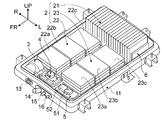
- FIG. 3 and 4 are diagrams illustrating details of the battery pack BP of the first embodiment. Hereinafter, based on FIG.3 and FIG.4, the detailed structure of the battery pack BP is demonstrated.
- the battery pack BP of the first embodiment includes a battery pack case 1, a battery module 2, a temperature control unit 3, and a service disconnect switch 4 (high-power cutoff switch: , “SD switch”), a junction box 5, and a lithium ion battery controller 6 (hereinafter referred to as “LB controller”).
- SD switch high-power cutoff switch
- LB controller lithium ion battery controller 6
- the battery pack case 1 is composed of two parts, a battery pack lower frame 11 and a battery pack upper cover 12, as shown in FIGS.
- the battery pack lower frame 11 is a frame member that is supported and fixed to the vehicle body member as shown in FIG.
- the battery pack lower frame 11 has a mounting space formed by a rectangular recess in which the battery module 2 and other pack components 3, 4, 5, and 6 are mounted.
- a refrigerant tube connector terminal 13, a battery-side high-power connector terminal 14, a PTC heater connector terminal 15, and a low-power connector terminal 16 are attached to the front end of the battery pack lower frame 11.
- the battery pack upper cover 12 is a cover member that is bolted to the outer peripheral portion of the battery pack lower frame 11 as shown in FIG.
- the battery pack upper cover 12 has an uneven step surface shape corresponding to the uneven height shape of the battery module 2 among the pack components 2, 3, 4, 5, 6 mounted on the battery pack lower frame 11. With a cover surface.
- the battery module 2 is mounted on the battery pack lower frame 11, and is configured by a three-divided module including a first battery module 21, a second battery module 22, and a third battery module 23.
- Each battery module 21, 22, 23 has an aggregate structure in which a plurality of battery cells made of secondary batteries (such as lithium ion batteries) are stacked.
- the detailed configuration of each battery module 21, 22, 23 is as follows.
- the first battery module 21 is mounted in the vehicle rear region of the battery pack lower frame 11 as shown in FIG.
- the first battery module 21 is prepared by stacking a plurality of battery cells in the thickness direction with a rectangular parallelepiped battery cell having a thin thickness as a structural unit. And it is comprised by the vertical stacking (for example, 20 vertical stacking) mounted so that the stacking direction of a battery cell and a vehicle width direction may correspond.
- each of the second battery module 22 and the third battery module 23 has left and right in the vehicle width direction in the vehicle central region of the battery pack lower frame 11 in front of the first battery module 21. A pair is mounted separately.
- the second battery module 22 and the third battery module 23 have a flat stacked structure with exactly the same pattern. That is, a rectangular parallelepiped battery cell having a small thickness is used as a structural unit, and a plurality of (for example, four and five) battery cells stacked in the thickness direction are stacked (for example, a set of four sheets, one set, five Prepare two sets).
- the second battery module 22 includes front battery module portions 22 a and 22 b and a rear battery module portion 22 c that is one sheet lower in height than the front battery module portions 22 a and 22 b.
- the third battery module 23 includes front battery module portions 23 a and 23 b and a rear battery module portion 23 c that is one sheet lower in height than the front battery module portions 23 a and 23 b. .
- the temperature control air unit 3 is disposed in the right side region of the vehicle front space in the battery pack lower frame 11 and blows temperature control air (cold air, hot air) to the air duct of the battery pack BP.
- temperature control air cold air, hot air
- coolant is introduce
- a heater operating current is introduced into the PTC heater of the temperature control air unit 3 via the junction box 5.
- the SD switch 4 is a switch that is disposed in the central region of the vehicle front space in the battery pack lower frame 11 and mechanically shuts off the battery high-power circuit by manual operation.
- the battery high-power circuit is formed by connecting each battery module 21, 22, 23 having an internal bus bar, the junction box 5, and the SD switch 4 to each other via the bus bar.
- the SD switch 4 can be switched on and off by manual operation when the high-power module 112, the inverter 113, etc. are inspected, repaired, or replaced.
- the junction box 5 is arranged in the left side region of the vehicle front space in the battery pack lower frame 11, and intensively supplies / cuts off / distributes high power by a relay circuit.
- the junction box 5 is provided with a temperature adjustment relay 51 and a temperature adjustment controller 52 for controlling the temperature adjustment air unit 3.
- the junction box 5 and the high voltage module 112 of the power unit PU are connected via the battery side high voltage connector terminal 14 and the high voltage harness 111.
- the junction box 5 and an external electronic control system are connected via a low-power connector terminal 16 and a low-power harness.
- the LB controller 6 is disposed at the left end face position of the first battery module 21 and performs capacity management, temperature management, and voltage management of the battery modules 21, 22, and 23.
- This LB controller 6 performs battery capacity information and battery temperature by arithmetic processing based on the temperature detection signal from the temperature detection signal line, the battery voltage detection value from the battery voltage detection line, and the battery current detection signal from the battery current detection signal line. Get information and battery voltage information.
- the LB controller 6 and an external electronic control system are connected via a light electrical harness that transmits relay circuit on / off information, battery capacity information, battery temperature information, and the like.
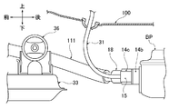
- FIGS. 5 to 8 are detailed views showing a high-voltage harness connection configuration of the battery pack BP and the power unit PU of the first embodiment.
- the connection configuration of the high-voltage harness 111 will be described with reference to FIGS.
- the high-voltage harness connection structure includes a battery pack BP disposed at a position below the floor of the vehicle, a power unit PU disposed at the vehicle front position of the battery pack BP, and a front end of the battery pack BP.
- a high-voltage connector terminal 18 that is inserted and connected to the battery-side high-voltage connector terminal 14 and a high-voltage connector terminal 19 that is connected to the unit-side high-voltage connector terminal 17 are provided.
- the battery pack BP has a refrigerant pipe connector terminal 13, a PTC heater connector terminal 15 (heater connector terminal), and a light electrical connector terminal 16 in addition to the battery-side high-power connector terminal 14 at its front end. Is provided.
- a refrigerant pipe 30 is connected to the refrigerant pipe connector terminal 13, a PTC heater harness 31 is connected to the PTC heater connector terminal 15, and a low electric harness 32 is connected to the low electric connector terminal 16.
- the battery pack BP has an arrangement setting in which the central axis of the battery pack coincides with the central axis CL in the vehicle front-rear direction.
- the power unit PU is elastically supported at three points via front power unit mounts 34 and 35 and a rear power unit mount 36 with respect to the suspension member 33 as shown in FIG.
- the suspension member 33 is elastically supported by four mounting portions 37, 37, 37, 37 with respect to a pair of left and right side members 109, 109 extending in the vehicle longitudinal direction.
- the front power unit mounts 34 and 35 elastically support the front left and right positions of the power unit PU.
- the rear power unit mount 36 elastically supports the position of the rear central portion of the power unit PU. As shown in FIG. 5, the rear power unit mount 36 has an elastic support point at a position slightly offset leftward from the central axis CL, not on the central axis CL in the vehicle longitudinal direction.
- the battery-side high-power connector terminal 14 has a harness connecting surface that is connected so that the high-power connector terminal 18 of the high-voltage harness 111 is inclined outward in the vehicle width direction with respect to the vehicle longitudinal direction.
- the connecting inclined surface 14a is used.
- the battery-side high-power connector terminal 14 is disposed at a position facing the floor tunnel portion 100 a provided on the floor panel 100.
- the high-voltage harness 111 routed toward the power unit PU has a horizontal inclination angle ⁇ (angle with respect to the vehicle longitudinal direction) of the harness connection inclined surface 14a along the floor tunnel portion 100a.
- ⁇ 35 degrees
- the battery-side high-power connector terminal 14 includes a connector base portion 14 b that protrudes obliquely outward from the front end portion of the battery pack BP, and a vehicle longitudinal direction with respect to the connector base portion 14 b. And a cylindrical connector terminal portion 14c connected to each other with an inclination angle.
- the connector base portion 14 b is a common component used as a connector base portion for the PTC heater connector terminal 15 and the low-power connector terminal 16 in addition to the battery-side high-power connector terminal 14. That is, the PTC heater connector terminal 15 is configured by connecting the connector terminal portion 15a to the connector base portion 14b.
- the light electrical connector terminal 16 is configured by connecting the connector terminal portion 16a to the connector base portion 14b.
- the PTC heater connector terminal 15 is connected to a PTC heater harness 31 that bends upward in the vehicle and penetrates the floor panel 100 as shown in FIG. This is because the bending limit of the PTC heater harness 31 is higher than the bending limit of the high voltage harness 111 and can be bent into a small radius arc. Then, as shown in FIGS. 5 and 7, the PTC heater connector terminal 15 is disposed at a position adjacent to the battery-side high-voltage connector terminal 14 and facing the rear power unit mount 36 in the vehicle front-rear direction. . As a result, the battery-side high-voltage connector terminal 14 disposed adjacent to the PTC heater connector terminal 15 is set at a position slightly away from the rear power unit mount 36 in the vehicle width direction.
- a battery-side high-voltage connector terminal 14 is provided at the front end portion of the battery pack BP disposed at a position below the floor of the vehicle.
- a unit-side high-voltage connector terminal 17 is provided in the power unit PU arranged at the vehicle front position of the battery pack BP. Then, by inserting the high-voltage connector terminals 18 and 19 at both ends into the battery-side high-voltage connector terminal 14 and the unit-side high-voltage connector terminal 17, the battery-side high-voltage connector terminal 14 and the unit-side high-voltage connector terminal 17 are Connected by harness 111.
- the harness connection surface of the battery-side high-voltage connector terminal 14 is a harness connection inclined surface 14a so that the high-voltage harness 111 is connected to the vehicle front-rear direction incline outward in the vehicle width direction. .
- the high-voltage harness 111 connected to the battery-side high-voltage connector terminal 14 side is inclined and connected to the vehicle width direction outer side with respect to the vehicle longitudinal direction.
- the interference with the high-voltage harness 111 with respect to the backward movement of the power unit PU is defined as the contact interference due to the inclination, so that the high-voltage harness even if the power unit PU moves backward due to an impact force when the front collision occurs. 111 is prevented from being damaged.
- the power unit PU and the battery pack BP are closer to each other in the vehicle front-rear direction than when the high-voltage harness is routed in the vehicle front-rear direction.
- the same size as in the case of the torsion beam type suspension is provided at the vehicle front position where interference with the leaf spring suspensions 121 and 121 is avoided.
- the battery pack BP can be placed.
- the vehicle wheel base length is the same, there will be enough space to allow the battery pack BP to have a longer vehicle front-rear dimension, and the number of cells mounted in the battery pack BP can be increased to increase the battery capacity.
- the battery pack BP arranged at the position under the floor of the vehicle has a degree of freedom for in-vehicle layout.
- the battery-side high-voltage connector terminal 14 is disposed at a position facing the floor tunnel portion 100 a provided on the floor panel 100.
- the high-voltage harness 111 that is routed toward the power unit PU with the inclination angle of the harness connection inclined surface 14a (horizontal inclination angle ⁇ ) can be bent and routed obliquely upward along the floor tunnel portion 100a. Adopted a configuration to set an appropriate angle. Therefore, the high-voltage harness 111 is configured to be bent and routed obliquely upward along the floor tunnel portion 100a in a bending margin state that does not reach the bending limit. For this reason, the detour routing along the floor tunnel part 100a is easily performed without bending the high-voltage harness 111 to the bending limit (see FIG. 8).
- the battery-side high-voltage connector terminal 14 is inclined with respect to the vehicle front-rear direction with respect to the connector base portion 14 b that protrudes inclined from the front end portion of the battery pack BP toward the vehicle width direction and the connector base portion 14 b.
- the structure which has the cylindrical connector terminal part 14c connected with an angle was employ
- the first embodiment employs a configuration in which the harness connection surface of the battery-side high-voltage connector terminal 14 is a harness connection inclined surface 14a having a horizontal inclination angle ⁇ outward in the vehicle width direction with respect to the vehicle longitudinal direction. Therefore, by having the horizontal inclination angle ⁇ in advance, the bending limit of the high-voltage harness 111 can be used for bending only in the vertical direction, and the configuration is easily bent and routed obliquely upward. For this reason, the connection workability
- the central position of the rear side of the power unit PU is elastically supported with respect to the suspension member 33 via the rear power unit mount 36.
- the structure which sets the battery side high electric connector terminal 14 in the position away in the vehicle front-back direction with respect to the rear power unit mount 36 among the front-end parts of battery pack BP was employ
- the heater connector terminal 15 is disposed at a position adjacent to the battery-side high-power connector terminal 14 and facing the rear power unit mount 36 in the vehicle front-rear direction. Therefore, the battery-side high-power connector terminal 14 is set to a position slightly deviated in the vehicle width direction from the position facing the rear power unit mount 36 in the vehicle front-rear direction. For this reason, when the front collision occurs, when the power unit PU moves backward due to the impact force, the contact interference due to the inclination of the high power harness 111 with respect to the rear power unit mount 36 is reduced, and the rear power unit mount 36 and the battery side strong power are reduced. Interference with the connector terminal 14 is prevented.
- the harness connection surface of the battery-side high-power connector terminal 14 is a harness connection inclined surface 14a so that the high-power harness 111 is connected to the vehicle front-rear direction inclined to the outside in the vehicle width direction (FIG. 5).
- the battery-side high-voltage connector terminal 14 is disposed at a position facing the floor tunnel portion 100a provided on the floor panel 100;
- the high-voltage harness 111 that is routed toward the power unit PU with the inclination angle (horizontal direction inclination angle ⁇ ) of the harness connection inclined surface 14a bent and routed obliquely upward along the floor tunnel portion 100a. was set to an angle where possible (FIG. 8). For this reason, in addition to the effect of (1), it is not necessary to bend the high-power harness 111 to the bending limit, and the detour routing work of the high-power harness 111 along the floor tunnel portion 100a can be easily performed.
- the battery-side high-voltage connector terminal 14 is inclined with respect to the vehicle front-rear direction with respect to the connector base portion 14b and the connector base portion 14b that is inclined and protrudes outward from the front end portion of the battery pack BP. And a cylindrical connector terminal portion 14c connected with an inclination angle (FIG. 6). For this reason, in addition to the effect of (1) or (2), the existing connector terminal is diverted and only the connector base portion 14b is changed, so that the battery-side high-voltage connector terminal 14 having the harness connection inclined surface 14a can be reduced in cost. Can be obtained.
- the harness connection inclined surface 14a of the battery-side high-voltage connector terminal 14 is a harness connection inclined surface having a horizontal inclination angle ⁇ outward in the vehicle width direction with respect to the vehicle longitudinal direction (FIG. 6). For this reason, in addition to the effects (1) to (3), it is possible to improve the connection workability of the high-voltage harness 111 from below the vehicle by using the bending limit of the high-voltage harness 111 for bending only in the vertical direction. it can.
- the rear central portion of the power unit PU is elastically supported with respect to the suspension member 33 via the rear power unit mount 36.
- the battery-side high-power connector terminal 14 was set at a position away from the rear power unit mount 36 in the vehicle front-rear direction in the front end portion of the battery pack BP (FIG. 5). For this reason, in addition to the effects (1) to (4), even if the high-voltage harness 111 interferes with the rear power unit mount 36 disposed at the rearmost position of the vehicle among the power units PU, the high-voltage harness 111 is damaged. Can be prevented.
- a heater connector terminal 15 to which a heater harness 31 penetrating the floor panel 100 is connected is provided at the front end of the battery pack BP.
- the heater connector terminal 15 is disposed at a position adjacent to the battery-side high-voltage connector terminal 14 and facing the rear power unit mount 36 in the vehicle front-rear direction (FIG. 7).
- the battery-side high-power connector terminal 14 is slightly disengaged in the vehicle width direction with respect to the rear power unit mount 36, so that the high-power harness 111 is inclined with respect to the rear power unit mount 36 when the power unit PU is retracted.
- interference between the rear power unit mount 36 and the battery-side high-voltage connector terminal 14 can be prevented.
- the high-voltage harness connection structure of the electric vehicle according to the present invention has been described based on the first embodiment.
- the specific configuration is not limited to the first embodiment, and the claims relate to each claim. Design changes and additions are allowed without departing from the scope of the invention.
- the harness connection inclined surface 14a having the horizontal inclination angle ⁇ is shown as the harness connection surface of the battery-side high-voltage connector terminal 14.
- the harness connection surface of the battery-side high-voltage connector terminal is a harness connection inclined surface having an inclination angle obliquely upward as long as the high-voltage harness is connected to the vehicle front-rear direction inclined to the vehicle width direction outside. It is good also as an example.
- Example 1 shows an example in which the high-voltage harness connection structure of the present invention is applied to a minivan type electric vehicle equipped with only a traveling motor as a driving source for traveling.
- the high-voltage harness connection structure for an electric vehicle according to the present invention can be applied to various electric vehicles such as a sedan type, a wagon type, and an SUV type in addition to the minivan type.
- the present invention can also be applied to a hybrid type electric vehicle (hybrid electric vehicle) equipped with a traveling motor and an engine as a traveling drive source.
- the present invention can be applied to any electric vehicle in which a battery-side high-voltage connector terminal provided at the front end of the battery pack and a unit-side high-voltage connector terminal provided in the power unit are connected by a high-voltage harness.
Landscapes
- Engineering & Computer Science (AREA)
- Mechanical Engineering (AREA)
- Transportation (AREA)
- Chemical & Material Sciences (AREA)
- Combustion & Propulsion (AREA)
- Sustainable Development (AREA)
- Life Sciences & Earth Sciences (AREA)
- Sustainable Energy (AREA)
- Power Engineering (AREA)
- General Chemical & Material Sciences (AREA)
- Electrochemistry (AREA)
- Chemical Kinetics & Catalysis (AREA)
- Arrangement Or Mounting Of Propulsion Units For Vehicles (AREA)
- Electric Propulsion And Braking For Vehicles (AREA)
Abstract
Description
この電動車両の強電ハーネス接続構造において、前記バッテリ側強電コネクタ端子のハーネス接続面を、前記強電ハーネスが車両前後方向に対して車幅方向外側へ傾斜して接続されるようにハーネス接続傾斜面とした。
したがって、パワーユニットと強電ハーネスが干渉したとしても、バッテリ側強電コネクタ端子側で車両前後方向に対して車幅方向外側へ傾斜して配索される強電ハーネスとは傾斜による接触干渉になる。すなわち、前突発生によりパワーユニットが車両後方に向かって後退しても、後退の進行に伴って強電ハーネスの車幅方向外側への傾斜角を大きくしたり、強電ハーネスの曲げ量を大きくしたりするにとどまる。
このように、パワーユニットの後退に対し強電ハーネスとの干渉を傾斜による接触干渉に規定する構成にしたことで、前突発生時、パワーユニットが衝撃力により車両後方に後退しても強電ハーネスが破損に至るのを防止することができる。
この結果、強電ハーネスを車両前後方向に配索させる場合に比べ、パワーユニットとバッテリパックの車両前後方向間隔をより近接した間隔にて配置することが可能となり、バッテリパックの車載レイアウト自由度が高められる。
実施例1の電動車両の強電ハーネス接続構造における構成を、「強電ハーネス接続構造を搭載した電気自動車の概略構成」、「バッテリパックBPの詳細構成」、「強電ハーネス接続構成」に分けて説明する。
図1及び図2は、実施例1の強電ハーネス接続構造を採用したミニバンタイプの電気自動車(電動車両の一例)を示す概略側面図及び概略底面図である。以下、図1及び図2に基づき、強電ハーネス接続構造を搭載した電気自動車の概略構成を説明する。
図3及び図4は、実施例1のバッテリパックBPの詳細を示す図である。以下、図3及び図4に基づき、バッテリパックBPの詳細構成を説明する。
図5~図8は、実施例1のバッテリパックBPとパワーユニットPUの強電ハーネス接続構成を示す詳細図である。以下、図5~図8に基づき、強電ハーネス111の接続構成を説明する。
実施例1の電気自動車の強電ハーネス接続構造におけるバッテリパックBPとパワーユニットPUの強電ハーネス接続作用を説明する。
したがって、強電ハーネス111が、曲げ限界に達さない曲げ余裕状態でフロアトンネル部100aに沿って斜め上方に屈曲配索される構成となる。このため、強電ハーネス111を曲げ限界まで屈曲させることなく、フロアトンネル部100aに沿う迂回配索が容易に行われる(図8参照)。
したがって、円筒状のコネクタ端子部14cとしては、既存のコネクタ端子を用いながら、コネクタベース部14bを変更するだけでバッテリ側強電コネクタ端子14が構成されることになる。このため、既存のコネクタ端子を流用することで、ハーネス接続傾斜面14aを有するバッテリ側強電コネクタ端子14が低コストにて得られる。
したがって、水平方向傾斜角度θを予め持っていることで、強電ハーネス111が持つ曲げ限界を垂直方向のみの曲げに用いることができ、容易に斜め上方に屈曲配索される構成となる。このため、車両下方からの強電ハーネス111の接続作業性の向上が図られる。
したがって、パワーユニットPUの後退時、リヤパワーユニットマウント36に対して強電ハーネス111が傾斜による接触干渉する構成となる。このため、前突発生時、パワーユニットPUが衝撃力により車両後方に後退したとき、リヤパワーユニットマウント36に対して強電ハーネス111が干渉しても、強電ハーネス111が破損に至るのが防止される。
したがって、バッテリ側強電コネクタ端子14が、リヤパワーユニットマウント36に対し車両前後方向に対向する位置から車幅方向に少し外れた位置への設定構成となる。このため、前突発生時、パワーユニットPUが衝撃力により車両後方に後退したとき、リヤパワーユニットマウント36に対する強電ハーネス111の傾斜による接触干渉が軽減されるのに加え、リヤパワーユニットマウント36とバッテリ側強電コネクタ端子14との干渉が防止される。
実施例1の電気自動車の強電ハーネス接続構造にあっては、下記に列挙する効果を得ることができる。
前記バッテリ側強電コネクタ端子14のハーネス接続面を、前記強電ハーネス111が車両前後方向に対して車幅方向外側へ傾斜して接続されるようにハーネス接続傾斜面14aとした(図5)。
このため、前突発生時、パワーユニットPUが衝撃力により車両後方に後退しても強電ハーネス111が破損に至るのを防止することができる。この結果、強電ハーネスを車両前後方向に配索させる場合に比べ、パワーユニットPUとバッテリパックBPの車両前後方向間隔をより近接した間隔にて配置することが可能となり、バッテリパックBPの車載レイアウト自由度が高められる。
前記ハーネス接続傾斜面14aの傾斜角度(水平方向傾斜角度θ)を、前記パワーユニットPUに向かって配索される前記強電ハーネス111が、前記フロアトンネル部100aに沿って斜め上方に屈曲配索することが可能な角度に設定した(図8)。
このため、(1)の効果に加え、強電ハーネス111を曲げ限界まで屈曲させることを要さず、フロアトンネル部100aに沿う強電ハーネス111の迂回配索作業を容易に行うことができる。
このため、(1)又は(2)の効果に加え、既存のコネクタ端子を流用し、コネクタベース部14bのみを変更することで、ハーネス接続傾斜面14aを有するバッテリ側強電コネクタ端子14を低コストにて得ることができる。
このため、(1)~(3)の効果に加え、強電ハーネス111が持つ曲げ限界を垂直方向のみの曲げに用いることで、車両下方からの強電ハーネス111の接続作業性の向上を図ることができる。
前記バッテリ側強電コネクタ端子14を、前記バッテリパックBPの前端部のうち、前記リヤパワーユニットマウント36に対して車両前後方向に離れた位置に設定した(図5)。
このため、(1)~(4)の効果に加え、パワーユニットPUのうち、最も車両後部位置に配置されるリヤパワーユニットマウント36に対して強電ハーネス111が干渉しても、強電ハーネス111が破損に至るのを防止することができる。
前記ヒータ用コネクタ端子15を、前記バッテリ側強電コネクタ端子14の隣接位置であって、前記リヤパワーユニットマウント36に対し車両前後方向に対向する位置に配置した(図7)。
このため、(5)の効果に加え、バッテリ側強電コネクタ端子14が、リヤパワーユニットマウント36に対し車幅方向に少し外れることで、パワーユニットPUの後退時、リヤパワーユニットマウント36に対する強電ハーネス111の傾斜による接触干渉を軽減することができるのに加え、リヤパワーユニットマウント36とバッテリ側強電コネクタ端子14との干渉を防止することができる。
Claims (6)
- 車両の床下位置に配置されたバッテリパックと、前記バッテリパックの車両前方位置に配置されたパワーユニットと、前記バッテリパックの前端部に設けられたバッテリ側強電コネクタ端子と前記パワーユニットに設けられたユニット側強電コネクタ端子を接続する強電ハーネスと、を備えた電動車両の強電ハーネス接続構造において、
前記バッテリ側強電コネクタ端子のハーネス接続面を、前記強電ハーネスが車両前後方向に対して車幅方向外側へ傾斜して接続されるようにハーネス接続傾斜面とした
ことを特徴とする電動車両の強電ハーネス接続構造。 - 請求項1に記載された電動車両の強電ハーネス接続構造において、
前記バッテリ側強電コネクタ端子を、フロアパネルに設けたフロアトンネル部に臨む位置に配置し、
前記ハーネス接続傾斜面の傾斜角度を、前記パワーユニットに向かって配索される前記強電ハーネスが、前記フロアトンネル部に沿って斜め上方に屈曲配索することが可能な角度に設定した
ことを特徴とする電動車両の強電ハーネス接続構造。 - 請求項1又は2に記載された電動車両の強電ハーネス接続構造において、
前記バッテリ側強電コネクタ端子は、前記バッテリパックの前端部から車幅方向外側に傾斜して突出するコネクタベース部と、該コネクタベース部に対し、車両前後方向に対して傾斜角度を持って連結される円筒状のコネクタ端子部と、を有する構成とした
ことを特徴とする電動車両の強電ハーネス接続構造。 - 請求項1から3までの何れか1項に記載された電動車両の強電ハーネス接続構造において、
前記バッテリ側強電コネクタ端子のハーネス接続傾斜面を、車両前後方向に対して車幅方向外側への水平方向傾斜角度を持つハーネス接続傾斜面とした
ことを特徴とする電動車両の強電ハーネス接続構造。 - 請求項1から4までの何れか1項に記載された電動車両の強電ハーネス接続構造において、
前記パワーユニットの後側中央部位置を、サスペンションメンバに対しリヤパワーユニットマウントを介して弾性支持し、
前記バッテリ側強電コネクタ端子を、前記バッテリパックの前端部のうち、前記リヤパワーユニットマウントに対して車両前後方向に離れた位置に設定した
ことを特徴とする電動車両の強電ハーネス接続構造。 - 請求項5に記載された電動車両の強電ハーネス接続構造において、
前記バッテリパックの前端部に、前記フロアパネルを貫通するヒータ用ハーネスが接続されるヒータ用コネクタ端子を設け、
前記ヒータ用コネクタ端子を、前記バッテリ側強電コネクタ端子の隣接位置であって、前記リヤパワーユニットマウントに対し車両前後方向に対向する位置に配置した
ことを特徴とする電動車両の強電ハーネス接続構造。
Priority Applications (4)
| Application Number | Priority Date | Filing Date | Title |
|---|---|---|---|
| CN201380044944.2A CN104602969B (zh) | 2012-08-27 | 2013-08-01 | 电动车辆的强电线束连接构造 |
| US14/420,918 US9260065B2 (en) | 2012-08-27 | 2013-08-01 | High-voltage harness connection structure for electrically driven vehicle |
| JP2014532897A JP5776852B2 (ja) | 2012-08-27 | 2013-08-01 | 電動車両の強電ハーネス接続構造 |
| EP13833032.9A EP2889185B1 (en) | 2012-08-27 | 2013-08-01 | High-voltage harness connection structure for electric vehicle |
Applications Claiming Priority (2)
| Application Number | Priority Date | Filing Date | Title |
|---|---|---|---|
| JP2012-186036 | 2012-08-27 | ||
| JP2012186036 | 2012-08-27 |
Publications (1)
| Publication Number | Publication Date |
|---|---|
| WO2014034377A1 true WO2014034377A1 (ja) | 2014-03-06 |
Family
ID=50183195
Family Applications (1)
| Application Number | Title | Priority Date | Filing Date |
|---|---|---|---|
| PCT/JP2013/070941 WO2014034377A1 (ja) | 2012-08-27 | 2013-08-01 | 電動車両の強電ハーネス接続構造 |
Country Status (4)
| Country | Link |
|---|---|
| US (1) | US9260065B2 (ja) |
| EP (1) | EP2889185B1 (ja) |
| JP (1) | JP5776852B2 (ja) |
| WO (1) | WO2014034377A1 (ja) |
Cited By (13)
| Publication number | Priority date | Publication date | Assignee | Title |
|---|---|---|---|---|
| EP2962882A1 (en) * | 2014-07-04 | 2016-01-06 | Mitsubishi Jidosha Kogyo Kabushiki Kaisha | Cable connecting structure of battery pack |
| JP2016055843A (ja) * | 2014-09-12 | 2016-04-21 | 三菱自動車工業株式会社 | 車両のケーブル配置構造 |
| JP2017197018A (ja) * | 2016-04-27 | 2017-11-02 | トヨタ自動車株式会社 | 車両のバッテリ搭載構造 |
| DE102019201063A1 (de) | 2018-01-30 | 2019-08-01 | Toyota Jidosha Kabushiki Kaisha | Fahrzeugvorderteilaufbau |
| EP3590792A1 (en) | 2018-07-03 | 2020-01-08 | Toyota Jidosha Kabushiki Kaisha | Vehicle front-part structure |
| JP2020040579A (ja) * | 2018-09-12 | 2020-03-19 | 本田技研工業株式会社 | 車両 |
| JP2020521671A (ja) * | 2017-05-30 | 2020-07-27 | フレット・ゲーエムベーハーFLET GmbH | 電気自動車 |
| JP2020196432A (ja) * | 2019-05-30 | 2020-12-10 | マツダ株式会社 | 電動車両の下部車体構造 |
| US11198472B2 (en) | 2019-06-28 | 2021-12-14 | Toyota Jidosha Kabushiki Kaisha | Vehicle lower-part structure |
| US11267326B2 (en) | 2019-06-28 | 2022-03-08 | Toyota Jidosha Kabushiki Kaisha | Vehicle lower-part structure |
| JP2022075930A (ja) * | 2017-08-28 | 2022-05-18 | スズキ株式会社 | 電動車両の車体構造 |
| US20220194205A1 (en) * | 2020-12-17 | 2022-06-23 | Volvo Car Corporation | Motor vehicle with an ice/bev combined scalable platform |
| WO2022191264A1 (ja) * | 2021-03-11 | 2022-09-15 | いすゞ自動車株式会社 | 車台 |
Families Citing this family (22)
| Publication number | Priority date | Publication date | Assignee | Title |
|---|---|---|---|---|
| US10249916B2 (en) * | 2015-04-13 | 2019-04-02 | Johnson Controls Technology Company | Connector barrel for a battery module |
| US10439182B2 (en) * | 2015-04-13 | 2019-10-08 | Cps Technology Holdings Llc | Connector barrel for a battery module |
| USD920251S1 (en) | 2015-09-10 | 2021-05-25 | Cps Technology Holdings Llc | Battery module connector barrel |
| KR102085344B1 (ko) * | 2016-10-24 | 2020-04-23 | 주식회사 엘지화학 | 차량용 배터리 팩 및 이를 포함하는 자동차 |
| US10632856B2 (en) * | 2017-01-19 | 2020-04-28 | Ford Global Technologies, Llc | Connector-integrated endplate for battery electric vehicles |
| CN110785306B (zh) * | 2017-08-31 | 2023-06-16 | 本田技研工业株式会社 | 电动车辆 |
| JP6582025B2 (ja) * | 2017-09-14 | 2019-09-25 | 本田技研工業株式会社 | バッテリユニット |
| JP7056468B2 (ja) * | 2018-08-24 | 2022-04-19 | トヨタ自動車株式会社 | 車両床下構造 |
| JP7091936B2 (ja) * | 2018-08-24 | 2022-06-28 | トヨタ自動車株式会社 | 車両床下構造 |
| US11367918B2 (en) * | 2018-11-13 | 2022-06-21 | Rivian Ip Holdings, Llc | Electric vehicle battery pack having external side pouch for electrical components |
| JP7056544B2 (ja) * | 2018-12-26 | 2022-04-19 | 株式会社オートネットワーク技術研究所 | ワイヤハーネス配索部材 |
| JP7191290B2 (ja) * | 2018-12-26 | 2022-12-19 | マツダ株式会社 | バッテリ搭載装置 |
| DE102019106424A1 (de) * | 2019-03-13 | 2020-09-17 | Bayerische Motoren Werke Aktiengesellschaft | Energiespeichereinrichtung für ein Kraftfahrzeug, Kraftfahrzeug sowie Herstellungsverfahren |
| JP7316523B2 (ja) * | 2019-04-24 | 2023-07-28 | マツダ株式会社 | 車両用バッテリ装置 |
| JP7276683B2 (ja) * | 2019-04-24 | 2023-05-18 | マツダ株式会社 | 車両用バッテリ装置 |
| JP2021138317A (ja) * | 2020-03-06 | 2021-09-16 | トヨタ自動車株式会社 | 車両ユニット搭載構造 |
| EP4144618A4 (en) * | 2020-04-28 | 2023-07-05 | Nissan Motor Co., Ltd. | ELECTRIC VEHICLE DISCONNECT PLUG STRUCTURE |
| US11848546B2 (en) * | 2021-02-01 | 2023-12-19 | Magna Powertrain Of America, Inc. | High voltage wire protection system for electric vehicles |
| JP2022150708A (ja) * | 2021-03-26 | 2022-10-07 | マツダ株式会社 | 電動車両の下部構造 |
| CN113173066A (zh) * | 2021-04-29 | 2021-07-27 | 重庆宗申创新技术研究院有限公司 | 一种中置发动机后悬挂安装装置及车辆 |
| US11901533B2 (en) * | 2021-06-02 | 2024-02-13 | Caterpillar Inc. | Sealed battery module with cooling and heating |
| JP2023124027A (ja) * | 2022-02-25 | 2023-09-06 | トヨタ自動車株式会社 | 高電圧ケーブル接続構造 |
Citations (3)
| Publication number | Priority date | Publication date | Assignee | Title |
|---|---|---|---|---|
| JP2011020622A (ja) * | 2009-07-17 | 2011-02-03 | Nissan Motor Co Ltd | 電気自動車の搭載構造 |
| JP2011126450A (ja) * | 2009-12-18 | 2011-06-30 | Nissan Motor Co Ltd | 電動車両用バッテリの取り付け構造 |
| JP2012096661A (ja) * | 2010-11-02 | 2012-05-24 | Honda Motor Co Ltd | パワーコントロールユニットの車体への取り付け構造及び電気自動車 |
Family Cites Families (12)
| Publication number | Priority date | Publication date | Assignee | Title |
|---|---|---|---|---|
| JPH054706Y2 (ja) * | 1988-02-15 | 1993-02-05 | ||
| US7028819B2 (en) * | 1996-02-21 | 2006-04-18 | Hitachi, Ltd. | Device and method for supplying power to a vehicle, semi-conductor circuit device for use in the same and collective wiring device for a vehicle or an automobile |
| JP3647693B2 (ja) * | 1999-10-22 | 2005-05-18 | 矢崎総業株式会社 | 車輌用ワイヤーハーネスの配索構造 |
| JP2002058149A (ja) * | 2000-06-02 | 2002-02-22 | Yazaki Corp | ワイヤーハーネス余長吸収装置 |
| JP2004224156A (ja) * | 2003-01-22 | 2004-08-12 | Honda Motor Co Ltd | 車両用電力ケーブル保持構造 |
| US7561445B2 (en) * | 2005-11-10 | 2009-07-14 | Nissan Motor Co., Ltd. | Harness routing structure for vehicle |
| JP5360689B2 (ja) * | 2009-09-24 | 2013-12-04 | スズキ株式会社 | 車両の高電圧ケーブルの配策構造 |
| JP5463953B2 (ja) * | 2010-02-26 | 2014-04-09 | 住友電気工業株式会社 | 細径同軸ケーブルハーネス及びその製造方法 |
| JP5572372B2 (ja) * | 2009-12-07 | 2014-08-13 | 矢崎総業株式会社 | ワイヤハーネスの配索構造及びワイヤハーネス |
| JP2011240799A (ja) * | 2010-05-18 | 2011-12-01 | Suzuki Motor Corp | 高電圧ユニットを搭載した車両 |
| JP2012014963A (ja) * | 2010-06-30 | 2012-01-19 | Sanyo Electric Co Ltd | 車両用の電源装置 |
| JP5494333B2 (ja) * | 2010-07-28 | 2014-05-14 | スズキ株式会社 | 自動車のケーブルの配索構造 |
-
2013
- 2013-08-01 EP EP13833032.9A patent/EP2889185B1/en active Active
- 2013-08-01 WO PCT/JP2013/070941 patent/WO2014034377A1/ja active Application Filing
- 2013-08-01 JP JP2014532897A patent/JP5776852B2/ja active Active
- 2013-08-01 US US14/420,918 patent/US9260065B2/en active Active
Patent Citations (3)
| Publication number | Priority date | Publication date | Assignee | Title |
|---|---|---|---|---|
| JP2011020622A (ja) * | 2009-07-17 | 2011-02-03 | Nissan Motor Co Ltd | 電気自動車の搭載構造 |
| JP2011126450A (ja) * | 2009-12-18 | 2011-06-30 | Nissan Motor Co Ltd | 電動車両用バッテリの取り付け構造 |
| JP2012096661A (ja) * | 2010-11-02 | 2012-05-24 | Honda Motor Co Ltd | パワーコントロールユニットの車体への取り付け構造及び電気自動車 |
Non-Patent Citations (1)
| Title |
|---|
| See also references of EP2889185A4 * |
Cited By (24)
| Publication number | Priority date | Publication date | Assignee | Title |
|---|---|---|---|---|
| CN105235487A (zh) * | 2014-07-04 | 2016-01-13 | 三菱自动车工业株式会社 | 蓄电池组的电缆连接结构 |
| US9531091B2 (en) | 2014-07-04 | 2016-12-27 | Mitsubishi Jidosha Kogyo Kabushiki Kaisha | Cable connecting structure of battery pack |
| EP2962882A1 (en) * | 2014-07-04 | 2016-01-06 | Mitsubishi Jidosha Kogyo Kabushiki Kaisha | Cable connecting structure of battery pack |
| JP2016055843A (ja) * | 2014-09-12 | 2016-04-21 | 三菱自動車工業株式会社 | 車両のケーブル配置構造 |
| JP2017197018A (ja) * | 2016-04-27 | 2017-11-02 | トヨタ自動車株式会社 | 車両のバッテリ搭載構造 |
| JP2020521671A (ja) * | 2017-05-30 | 2020-07-27 | フレット・ゲーエムベーハーFLET GmbH | 電気自動車 |
| US11292325B2 (en) | 2017-05-30 | 2022-04-05 | Flet Gmbh | Electric car |
| JP7227573B2 (ja) | 2017-08-28 | 2023-02-22 | スズキ株式会社 | 電動車両の車体構造 |
| JP2022075930A (ja) * | 2017-08-28 | 2022-05-18 | スズキ株式会社 | 電動車両の車体構造 |
| US11124135B2 (en) | 2018-01-30 | 2021-09-21 | Toyota Jidosha Kabushiki Kaisha | Vehicle front-part structure |
| DE102019201063A1 (de) | 2018-01-30 | 2019-08-01 | Toyota Jidosha Kabushiki Kaisha | Fahrzeugvorderteilaufbau |
| EP3590792A1 (en) | 2018-07-03 | 2020-01-08 | Toyota Jidosha Kabushiki Kaisha | Vehicle front-part structure |
| US11027782B2 (en) | 2018-07-03 | 2021-06-08 | Toyota Jidosha Kabushiki Kaisha | Vehicle front-part structure |
| EP4328056A2 (en) | 2018-07-03 | 2024-02-28 | Toyota Jidosha Kabushiki Kaisha | Vehicle front-part structure |
| CN110893757A (zh) * | 2018-09-12 | 2020-03-20 | 本田技研工业株式会社 | 车辆 |
| JP2020040579A (ja) * | 2018-09-12 | 2020-03-19 | 本田技研工業株式会社 | 車両 |
| CN110893757B (zh) * | 2018-09-12 | 2023-03-03 | 本田技研工业株式会社 | 车辆 |
| JP2020196432A (ja) * | 2019-05-30 | 2020-12-10 | マツダ株式会社 | 電動車両の下部車体構造 |
| JP7232422B2 (ja) | 2019-05-30 | 2023-03-03 | マツダ株式会社 | 電動車両の下部車体構造 |
| US11198472B2 (en) | 2019-06-28 | 2021-12-14 | Toyota Jidosha Kabushiki Kaisha | Vehicle lower-part structure |
| US11267326B2 (en) | 2019-06-28 | 2022-03-08 | Toyota Jidosha Kabushiki Kaisha | Vehicle lower-part structure |
| US20220194205A1 (en) * | 2020-12-17 | 2022-06-23 | Volvo Car Corporation | Motor vehicle with an ice/bev combined scalable platform |
| WO2022191264A1 (ja) * | 2021-03-11 | 2022-09-15 | いすゞ自動車株式会社 | 車台 |
| JP2022138927A (ja) * | 2021-03-11 | 2022-09-26 | いすゞ自動車株式会社 | 車台 |
Also Published As
| Publication number | Publication date |
|---|---|
| EP2889185A4 (en) | 2015-09-16 |
| US20150217707A1 (en) | 2015-08-06 |
| EP2889185B1 (en) | 2018-02-21 |
| EP2889185A1 (en) | 2015-07-01 |
| CN104602969A (zh) | 2015-05-06 |
| JP5776852B2 (ja) | 2015-09-09 |
| JPWO2014034377A1 (ja) | 2016-08-08 |
| US9260065B2 (en) | 2016-02-16 |
Similar Documents
| Publication | Publication Date | Title |
|---|---|---|
| JP5776852B2 (ja) | 電動車両の強電ハーネス接続構造 | |
| JP6210092B2 (ja) | 自動車 | |
| JP5807476B2 (ja) | 電気自動車のバッテリパック車体支持構造 | |
| CN112188968B (zh) | 电动车辆 | |
| JP5854149B2 (ja) | 電気自動車の車体構造 | |
| US8205700B2 (en) | Power storage device | |
| US8928279B2 (en) | Electric vehicle structure | |
| WO2013084942A1 (ja) | 電気自動車用バッテリパック | |
| WO2012157316A1 (ja) | 電気自動車の充放電ハーネス配索構造 | |
| JP6706507B2 (ja) | 車両 | |
| US20170355272A1 (en) | In-vehicle structure of electric-power converter | |
| CN101312855B (zh) | 束线排布结构 | |
| JP2015157584A (ja) | 車載用バッテリー | |
| US9531091B2 (en) | Cable connecting structure of battery pack | |
| JP2011006050A (ja) | 電気自動車の電気部品搭載構造 | |
| JP2010023636A (ja) | 電動車両 | |
| JP2020185953A (ja) | 車両用バッテリユニット | |
| WO2013072962A1 (ja) | 車両 | |
| US11370371B2 (en) | Vehicle | |
| JP2019209717A (ja) | 給電ユニット | |
| WO2011145577A1 (ja) | 高電圧ユニットの保護構造 | |
| JP2017077786A (ja) | 車両 | |
| JP6525657B2 (ja) | 車載用バッテリー | |
| CN113113693A (zh) | 电池冷却结构 | |
| JP2016150717A (ja) | 車両用ハーネスの配索構造 |
Legal Events
| Date | Code | Title | Description |
|---|---|---|---|
| 121 | Ep: the epo has been informed by wipo that ep was designated in this application |
Ref document number: 13833032 Country of ref document: EP Kind code of ref document: A1 |
|
| ENP | Entry into the national phase |
Ref document number: 2014532897 Country of ref document: JP Kind code of ref document: A |
|
| WWE | Wipo information: entry into national phase |
Ref document number: 2013833032 Country of ref document: EP |
|
| WWE | Wipo information: entry into national phase |
Ref document number: 14420918 Country of ref document: US |
|
| NENP | Non-entry into the national phase |
Ref country code: DE |