EP2962882A1 - Cable connecting structure of battery pack - Google Patents
Cable connecting structure of battery pack Download PDFInfo
- Publication number
- EP2962882A1 EP2962882A1 EP15175212.8A EP15175212A EP2962882A1 EP 2962882 A1 EP2962882 A1 EP 2962882A1 EP 15175212 A EP15175212 A EP 15175212A EP 2962882 A1 EP2962882 A1 EP 2962882A1
- Authority
- EP
- European Patent Office
- Prior art keywords
- battery pack
- quick charging
- cable
- connectors
- cables
- Prior art date
- Legal status (The legal status is an assumption and is not a legal conclusion. Google has not performed a legal analysis and makes no representation as to the accuracy of the status listed.)
- Granted
Links
- 230000002093 peripheral effect Effects 0.000 claims abstract description 53
- 230000007246 mechanism Effects 0.000 description 3
- 230000000994 depressogenic effect Effects 0.000 description 2
- 229910000831 Steel Inorganic materials 0.000 description 1
- 230000001627 detrimental effect Effects 0.000 description 1
- 230000000694 effects Effects 0.000 description 1
- 239000000463 material Substances 0.000 description 1
- 239000010959 steel Substances 0.000 description 1
- 239000000725 suspension Substances 0.000 description 1
- 238000003466 welding Methods 0.000 description 1
Images


Classifications
-
- B—PERFORMING OPERATIONS; TRANSPORTING
- B60—VEHICLES IN GENERAL
- B60K—ARRANGEMENT OR MOUNTING OF PROPULSION UNITS OR OF TRANSMISSIONS IN VEHICLES; ARRANGEMENT OR MOUNTING OF PLURAL DIVERSE PRIME-MOVERS IN VEHICLES; AUXILIARY DRIVES FOR VEHICLES; INSTRUMENTATION OR DASHBOARDS FOR VEHICLES; ARRANGEMENTS IN CONNECTION WITH COOLING, AIR INTAKE, GAS EXHAUST OR FUEL SUPPLY OF PROPULSION UNITS IN VEHICLES
- B60K1/00—Arrangement or mounting of electrical propulsion units
- B60K1/04—Arrangement or mounting of electrical propulsion units of the electric storage means for propulsion
-
- B—PERFORMING OPERATIONS; TRANSPORTING
- B60—VEHICLES IN GENERAL
- B60L—PROPULSION OF ELECTRICALLY-PROPELLED VEHICLES; SUPPLYING ELECTRIC POWER FOR AUXILIARY EQUIPMENT OF ELECTRICALLY-PROPELLED VEHICLES; ELECTRODYNAMIC BRAKE SYSTEMS FOR VEHICLES IN GENERAL; MAGNETIC SUSPENSION OR LEVITATION FOR VEHICLES; MONITORING OPERATING VARIABLES OF ELECTRICALLY-PROPELLED VEHICLES; ELECTRIC SAFETY DEVICES FOR ELECTRICALLY-PROPELLED VEHICLES
- B60L50/00—Electric propulsion with power supplied within the vehicle
- B60L50/50—Electric propulsion with power supplied within the vehicle using propulsion power supplied by batteries or fuel cells
- B60L50/60—Electric propulsion with power supplied within the vehicle using propulsion power supplied by batteries or fuel cells using power supplied by batteries
- B60L50/64—Constructional details of batteries specially adapted for electric vehicles
-
- B—PERFORMING OPERATIONS; TRANSPORTING
- B60—VEHICLES IN GENERAL
- B60L—PROPULSION OF ELECTRICALLY-PROPELLED VEHICLES; SUPPLYING ELECTRIC POWER FOR AUXILIARY EQUIPMENT OF ELECTRICALLY-PROPELLED VEHICLES; ELECTRODYNAMIC BRAKE SYSTEMS FOR VEHICLES IN GENERAL; MAGNETIC SUSPENSION OR LEVITATION FOR VEHICLES; MONITORING OPERATING VARIABLES OF ELECTRICALLY-PROPELLED VEHICLES; ELECTRIC SAFETY DEVICES FOR ELECTRICALLY-PROPELLED VEHICLES
- B60L50/00—Electric propulsion with power supplied within the vehicle
- B60L50/50—Electric propulsion with power supplied within the vehicle using propulsion power supplied by batteries or fuel cells
- B60L50/60—Electric propulsion with power supplied within the vehicle using propulsion power supplied by batteries or fuel cells using power supplied by batteries
- B60L50/66—Arrangements of batteries
-
- B—PERFORMING OPERATIONS; TRANSPORTING
- B60—VEHICLES IN GENERAL
- B60L—PROPULSION OF ELECTRICALLY-PROPELLED VEHICLES; SUPPLYING ELECTRIC POWER FOR AUXILIARY EQUIPMENT OF ELECTRICALLY-PROPELLED VEHICLES; ELECTRODYNAMIC BRAKE SYSTEMS FOR VEHICLES IN GENERAL; MAGNETIC SUSPENSION OR LEVITATION FOR VEHICLES; MONITORING OPERATING VARIABLES OF ELECTRICALLY-PROPELLED VEHICLES; ELECTRIC SAFETY DEVICES FOR ELECTRICALLY-PROPELLED VEHICLES
- B60L53/00—Methods of charging batteries, specially adapted for electric vehicles; Charging stations or on-board charging equipment therefor; Exchange of energy storage elements in electric vehicles
- B60L53/10—Methods of charging batteries, specially adapted for electric vehicles; Charging stations or on-board charging equipment therefor; Exchange of energy storage elements in electric vehicles characterised by the energy transfer between the charging station and the vehicle
- B60L53/11—DC charging controlled by the charging station, e.g. mode 4
-
- B—PERFORMING OPERATIONS; TRANSPORTING
- B60—VEHICLES IN GENERAL
- B60L—PROPULSION OF ELECTRICALLY-PROPELLED VEHICLES; SUPPLYING ELECTRIC POWER FOR AUXILIARY EQUIPMENT OF ELECTRICALLY-PROPELLED VEHICLES; ELECTRODYNAMIC BRAKE SYSTEMS FOR VEHICLES IN GENERAL; MAGNETIC SUSPENSION OR LEVITATION FOR VEHICLES; MONITORING OPERATING VARIABLES OF ELECTRICALLY-PROPELLED VEHICLES; ELECTRIC SAFETY DEVICES FOR ELECTRICALLY-PROPELLED VEHICLES
- B60L53/00—Methods of charging batteries, specially adapted for electric vehicles; Charging stations or on-board charging equipment therefor; Exchange of energy storage elements in electric vehicles
- B60L53/10—Methods of charging batteries, specially adapted for electric vehicles; Charging stations or on-board charging equipment therefor; Exchange of energy storage elements in electric vehicles characterised by the energy transfer between the charging station and the vehicle
- B60L53/14—Conductive energy transfer
-
- H—ELECTRICITY
- H01—ELECTRIC ELEMENTS
- H01M—PROCESSES OR MEANS, e.g. BATTERIES, FOR THE DIRECT CONVERSION OF CHEMICAL ENERGY INTO ELECTRICAL ENERGY
- H01M50/00—Constructional details or processes of manufacture of the non-active parts of electrochemical cells other than fuel cells, e.g. hybrid cells
- H01M50/20—Mountings; Secondary casings or frames; Racks, modules or packs; Suspension devices; Shock absorbers; Transport or carrying devices; Holders
- H01M50/249—Mountings; Secondary casings or frames; Racks, modules or packs; Suspension devices; Shock absorbers; Transport or carrying devices; Holders specially adapted for aircraft or vehicles, e.g. cars or trains
-
- H—ELECTRICITY
- H01—ELECTRIC ELEMENTS
- H01M—PROCESSES OR MEANS, e.g. BATTERIES, FOR THE DIRECT CONVERSION OF CHEMICAL ENERGY INTO ELECTRICAL ENERGY
- H01M50/00—Constructional details or processes of manufacture of the non-active parts of electrochemical cells other than fuel cells, e.g. hybrid cells
- H01M50/20—Mountings; Secondary casings or frames; Racks, modules or packs; Suspension devices; Shock absorbers; Transport or carrying devices; Holders
- H01M50/298—Mountings; Secondary casings or frames; Racks, modules or packs; Suspension devices; Shock absorbers; Transport or carrying devices; Holders characterised by the wiring of battery packs
-
- H—ELECTRICITY
- H01—ELECTRIC ELEMENTS
- H01R—ELECTRICALLY-CONDUCTIVE CONNECTIONS; STRUCTURAL ASSOCIATIONS OF A PLURALITY OF MUTUALLY-INSULATED ELECTRICAL CONNECTING ELEMENTS; COUPLING DEVICES; CURRENT COLLECTORS
- H01R11/00—Individual connecting elements providing two or more spaced connecting locations for conductive members which are, or may be, thereby interconnected, e.g. end pieces for wires or cables supported by the wire or cable and having means for facilitating electrical connection to some other wire, terminal, or conductive member, blocks of binding posts
- H01R11/11—End pieces or tapping pieces for wires, supported by the wire and for facilitating electrical connection to some other wire, terminal or conductive member
- H01R11/28—End pieces consisting of a ferrule or sleeve
- H01R11/281—End pieces consisting of a ferrule or sleeve for connections to batteries
- H01R11/282—End pieces consisting of a ferrule or sleeve for connections to batteries comprising means for facilitating engagement or disengagement, e.g. quick release terminal
-
- B—PERFORMING OPERATIONS; TRANSPORTING
- B60—VEHICLES IN GENERAL
- B60K—ARRANGEMENT OR MOUNTING OF PROPULSION UNITS OR OF TRANSMISSIONS IN VEHICLES; ARRANGEMENT OR MOUNTING OF PLURAL DIVERSE PRIME-MOVERS IN VEHICLES; AUXILIARY DRIVES FOR VEHICLES; INSTRUMENTATION OR DASHBOARDS FOR VEHICLES; ARRANGEMENTS IN CONNECTION WITH COOLING, AIR INTAKE, GAS EXHAUST OR FUEL SUPPLY OF PROPULSION UNITS IN VEHICLES
- B60K1/00—Arrangement or mounting of electrical propulsion units
- B60K1/04—Arrangement or mounting of electrical propulsion units of the electric storage means for propulsion
- B60K2001/0405—Arrangement or mounting of electrical propulsion units of the electric storage means for propulsion characterised by their position
- B60K2001/0438—Arrangement under the floor
-
- B—PERFORMING OPERATIONS; TRANSPORTING
- B60—VEHICLES IN GENERAL
- B60Y—INDEXING SCHEME RELATING TO ASPECTS CROSS-CUTTING VEHICLE TECHNOLOGY
- B60Y2410/00—Constructional features of vehicle sub-units
- B60Y2410/115—Electric wiring; Electric connectors
-
- H—ELECTRICITY
- H01—ELECTRIC ELEMENTS
- H01M—PROCESSES OR MEANS, e.g. BATTERIES, FOR THE DIRECT CONVERSION OF CHEMICAL ENERGY INTO ELECTRICAL ENERGY
- H01M2220/00—Batteries for particular applications
- H01M2220/20—Batteries in motive systems, e.g. vehicle, ship, plane
-
- Y—GENERAL TAGGING OF NEW TECHNOLOGICAL DEVELOPMENTS; GENERAL TAGGING OF CROSS-SECTIONAL TECHNOLOGIES SPANNING OVER SEVERAL SECTIONS OF THE IPC; TECHNICAL SUBJECTS COVERED BY FORMER USPC CROSS-REFERENCE ART COLLECTIONS [XRACs] AND DIGESTS
- Y02—TECHNOLOGIES OR APPLICATIONS FOR MITIGATION OR ADAPTATION AGAINST CLIMATE CHANGE
- Y02E—REDUCTION OF GREENHOUSE GAS [GHG] EMISSIONS, RELATED TO ENERGY GENERATION, TRANSMISSION OR DISTRIBUTION
- Y02E60/00—Enabling technologies; Technologies with a potential or indirect contribution to GHG emissions mitigation
- Y02E60/10—Energy storage using batteries
-
- Y—GENERAL TAGGING OF NEW TECHNOLOGICAL DEVELOPMENTS; GENERAL TAGGING OF CROSS-SECTIONAL TECHNOLOGIES SPANNING OVER SEVERAL SECTIONS OF THE IPC; TECHNICAL SUBJECTS COVERED BY FORMER USPC CROSS-REFERENCE ART COLLECTIONS [XRACs] AND DIGESTS
- Y02—TECHNOLOGIES OR APPLICATIONS FOR MITIGATION OR ADAPTATION AGAINST CLIMATE CHANGE
- Y02T—CLIMATE CHANGE MITIGATION TECHNOLOGIES RELATED TO TRANSPORTATION
- Y02T10/00—Road transport of goods or passengers
- Y02T10/60—Other road transportation technologies with climate change mitigation effect
- Y02T10/70—Energy storage systems for electromobility, e.g. batteries
-
- Y—GENERAL TAGGING OF NEW TECHNOLOGICAL DEVELOPMENTS; GENERAL TAGGING OF CROSS-SECTIONAL TECHNOLOGIES SPANNING OVER SEVERAL SECTIONS OF THE IPC; TECHNICAL SUBJECTS COVERED BY FORMER USPC CROSS-REFERENCE ART COLLECTIONS [XRACs] AND DIGESTS
- Y02—TECHNOLOGIES OR APPLICATIONS FOR MITIGATION OR ADAPTATION AGAINST CLIMATE CHANGE
- Y02T—CLIMATE CHANGE MITIGATION TECHNOLOGIES RELATED TO TRANSPORTATION
- Y02T10/00—Road transport of goods or passengers
- Y02T10/60—Other road transportation technologies with climate change mitigation effect
- Y02T10/7072—Electromobility specific charging systems or methods for batteries, ultracapacitors, supercapacitors or double-layer capacitors
-
- Y—GENERAL TAGGING OF NEW TECHNOLOGICAL DEVELOPMENTS; GENERAL TAGGING OF CROSS-SECTIONAL TECHNOLOGIES SPANNING OVER SEVERAL SECTIONS OF THE IPC; TECHNICAL SUBJECTS COVERED BY FORMER USPC CROSS-REFERENCE ART COLLECTIONS [XRACs] AND DIGESTS
- Y02—TECHNOLOGIES OR APPLICATIONS FOR MITIGATION OR ADAPTATION AGAINST CLIMATE CHANGE
- Y02T—CLIMATE CHANGE MITIGATION TECHNOLOGIES RELATED TO TRANSPORTATION
- Y02T90/00—Enabling technologies or technologies with a potential or indirect contribution to GHG emissions mitigation
- Y02T90/10—Technologies relating to charging of electric vehicles
- Y02T90/12—Electric charging stations
-
- Y—GENERAL TAGGING OF NEW TECHNOLOGICAL DEVELOPMENTS; GENERAL TAGGING OF CROSS-SECTIONAL TECHNOLOGIES SPANNING OVER SEVERAL SECTIONS OF THE IPC; TECHNICAL SUBJECTS COVERED BY FORMER USPC CROSS-REFERENCE ART COLLECTIONS [XRACs] AND DIGESTS
- Y02—TECHNOLOGIES OR APPLICATIONS FOR MITIGATION OR ADAPTATION AGAINST CLIMATE CHANGE
- Y02T—CLIMATE CHANGE MITIGATION TECHNOLOGIES RELATED TO TRANSPORTATION
- Y02T90/00—Enabling technologies or technologies with a potential or indirect contribution to GHG emissions mitigation
- Y02T90/10—Technologies relating to charging of electric vehicles
- Y02T90/14—Plug-in electric vehicles
Definitions
- the present invention relates to a cable connecting structure of a battery pack.
- the two charging cables are detachably connected to the battery pack by way of a single connector.
- a single cable side connector is provided in end parts of the two charging cables which are connected to the charging port, and at the same time, a single battery pack side connector to be connected to a battery inside the battery pack is provided on a peripheral face of the battery pack.
- both the cable side connector and the battery pack side connector are single components to which the two cables are respectively connected, and therefore, the connectors must have a large size to some extent.
- the peripheral face of the battery pack inevitably has a large size in a vertical direction, which is detrimental in making the battery pack compact.
- the battery side connector and the cable side connector are so constructed that their axes are perpendicular to the peripheral face of the battery pack, in many cases. Accordingly, the two cables withdrawn from the cable side connector which is mounted to the battery pack side connector is extended in a direction perpendicular to the peripheral face of the battery pack. Therefore, it is disadvantageous that a large space for wiring the cables must be secured around the peripheral face of the battery pack.
- a cable connecting structure of a battery pack the battery pack which is provided in a vehicle, the cable connecting structure comprising: a plurality of cable side connectors which are provided at ends of a plurality of cables, respectively, and which are connected to the battery pack; and a plurality of battery pack side connectors to which the cable side connectors are detachably mounted, and which are arranged in parallel along a peripheral direction of a peripheral wall of the battery pack, wherein, in a state where the cable side connectors are mounted to the battery pack side connectors, portions of the cables which are respectively withdrawn from the cable side connectors are extended along the peripheral wall.
- the cables may be extended from the cable side connectors, respectively, so as to be parallel to each other, or may be extended from the cable side connectors in a direction in which the cables are separated from each other.
- At least one of the battery pack side connectors which are adjacent to each other may have an axis inclined with respect to the peripheral wall, in a plan view of the battery pack, and the portion of the cable withdrawn from the cable side connector which is mounted to the battery pack side connector the axis of which is inclined may be separated from the peripheral wall, as going away from the battery pack connector the axis of which is inclined.
- the battery pack side connectors may have mounting faces to which the cable side connectors are mounted, and the mounting face of one of the battery pack side connectors which are adjacent to each other may be positioned more outward of the battery pack than the mounting face of the other battery pack side connector.
- the battery pack side connectors may have mounting faces to which the cable side connectors are mounted, and at least two of the mounting faces of the battery pack side connectors may have the same height from the peripheral wall of the battery pack.
- At least two of the cables may be respectively connected to a positive terminal and a negative terminal of a charging port of the vehicle which is connected to an external power supply, and two battery pack side connectors to which the cable side connectors of the at least two cables are mounted may be disposed on one of a frontward face and a rearward face of the peripheral wall of the battery pack which is closer to the charging port.
- the vehicle to which the cable connecting structure of the battery pack according to the invention is applied is an electric motor car employing only a motor as a driving source
- the invention is not only applied to the electric motor car, but can be widely applied to other vehicles, provided that the battery pack is provided under floor.
- the invention can be widely applied to electrically driven cars such as a hybrid car, a plug-in hybrid car, and so on.
- a vehicle 10 includes a vehicle body 12, a driving motor which is not shown, front wheels which are not shown, rear wheels 14, a quick charging port 16, a battery pack 18, battery pack side connectors 20 (20A, 20B), quick charging cables 22 (22A, 22B), and cable side connectors 24 (24A, 24B).
- this embodiment relates to a cable connecting structure of the battery pack 18 in which a plurality of the cable side connectors 24 are connected to the quick charging port 16, which is an electrical component, at their one ends, and connected to the battery pack 18, at their other ends.
- the vehicle body 12 includes a pair of right and left side members, a plurality of cross members, and a floor panel which is provided above these side members and cross members, all of which are not shown.
- the floor panel which is disposed in a lower part of the vehicle body is formed of steel sheet, and extended both in a longitudinal direction and in a lateral direction of the vehicle. Both sides in the lateral direction of a lower face of the floor panel are joined to the two side members by welding.
- the driving motor is disposed in a rear part of the vehicle body 12, and actuated by an electric power which is supplied from the battery pack 18 via an inverter thereby to rotate the rear wheels 14.
- a charging gun of a quick charging device which is an external power supply, is attached to the quick charging port 16 thereby to supply a high voltage electric power.
- This quick charging port 16 is provided with a positive terminal and a negative terminal, and in this embodiment, this quick charging port 16 is an electrical component.
- the quick charging port 16 is provided at a position above the rear wheel 14 on a rearward left side face of the vehicle body 12.
- the battery pack 18 is disposed below a floor panel 28 between a pair of the right and left side members, and includes a battery for driving, which is not shown, and a battery case 18A which contains this battery.
- the battery includes a plurality of battery modules which are connected to each other in series, and peripheral components for enabling these battery modules to function.
- Each of the battery modules includes a plurality of battery cells which are connected to each other in series.
- the battery case 18A has a shape of a rectangular plate in a plan view, and is disposed in a center part in the lateral direction of the vehicle, having its longitudinal direction aligned with a longitudinal direction of the vehicle 10.
- the battery case 18A is disposed between a pair of the side members below the floor panel, and fitted to the two side members via a fitting member.
- the battery case 18A includes an upper wall 1802 directed upward, a lower wall 1804 directed downward, and a peripheral wall 1805 which is directed in the longitudinal direction and the lateral direction of the vehicle 10, that is, in a direction perpendicular to the vertical direction, for connecting the upper wall 1802 and the lower wall 1804 to each other.
- the peripheral wall 1805 includes a front wall 1806 directed to a front side of the vehicle, and a rear wall 1808 directed to a rear side of the vehicle, a left side wall 1810 directed to a left side in the lateral direction, and a right side wall 1812 directed to a right side in the lateral direction.
- a distance between the rear wall 1808 of the battery case 18A and the two rear wheels 14 is small, because the vehicle 10 is a light-duty car or a compact car.
- components for mechanisms such as a suspension mechanism, a brake mechanism, and various wiring materials are provided between the two rear wheels 14 which have a small distance between them. Therefore, there is a complicated space in rear of the rear wall 1808 of the battery pack 18.
- the battery pack side connector 20 includes two battery pack side quick charging connectors 20A, 20B which are adjacent to each other, namely, a positive battery pack side connector which is connected to the positive terminal of the battery via the peripheral components, and a negative battery pack side connector which is connected to the negative terminal of the battery via the peripheral components.
- the two battery pack side quick charging connectors 20A, 20B are arranged in parallel along a peripheral direction of the peripheral wall 1805.
- the two battery pack side quick charging connectors 20A, 20B are provided on the rear wall 1808 in the lateral direction of the vehicle, that is, an extending direction of the rear wall 1808.
- the two battery pack side quick charging connectors 20A, 20B are mounted to the rear wall 1808 via a mounting bracket 26.
- the two battery pack side quick charging connectors 20A, 20B are arranged in such a manner that their axes LA, LB are inclined with respect to the rear wall 1808.
- the two battery pack side quick charging connectors 20A, 20B respectively have mounting faces 2002 to which the cable side quick charging connectors 24A, 24B are mounted. These mounting faces 2002 are perpendicular to the axes LA, LB.
- the cable side connectors 24A, 24B at respective ends of the two quick charging cables 22A, 22B which are connected to the quick charging port 16 are detachably mounted to the two battery pack side quick charging connectors 20A, 20B.
- the two quick charging cables 22A, 22B are respectively formed of single core cables.
- One of the two quick charging cables 22A, 22B is the positive side quick charging cable which is connected to a positive terminal of the quick charging port 16, and the other is a negative side quick charging cable which is connected to the negative terminal of the quick charging port 16.
- the two quick charging cables 22A, 22B have a large outer diameter and high rigidity, because a large amount of electric current flows through them.
- the cable side connector 24 includes the two cable side quick charging connectors 24A, 24B, namely, a positive side quick charging connector which is connected to the positive side quick charging cable, and a negative side quick charging connector which is connected to the negative side quick charging cable.
- the two cable side quick charging connectors 24A, 24B and the two battery pack side quick charging connectors 20A, 20B are constructed in such a manner that in a state where the two cable side quick charging connectors 24A, 24B are mounted to the two battery pack side quick charging connectors 20A, 20B, portions 2202 of the two quick charging cables 22A, 22B which are respectively withdrawn from the cable side quick charging connectors 24A, 24B are extended along the rear wall 1808.
- the cable side quick charging connectors 24A, 24B and the battery pack side quick charging connectors 20A, 20B are constructed in such a manner that in a state where the connectors are mounted to each other having their axes aligned, the respective portions 2202 of the quick charging cables 22A, 22B withdrawn from the cable side quick charging connectors 24A, 24B are perpendicular to the axes of the cable side quick charging connectors 24.
- the portions 2202 of the quick charging cables 22A, 22B withdrawn from the cable side quick charging connectors 24A, 24B which are mounted to the battery pack side quick charging connectors 20A, 20B which are inclined are so formed as to be separated from the rear wall 1808, as going away from the inclined battery pack side quick charging connectors 20A, 20B.
- an inclination angle ⁇ of the axis LA of the battery pack side quick charging connector 20A which is close to the quick charging port 16 with respect to the rear wall 1808, out of two battery pack side quick charging connectors 20A, 20B, is larger than an inclination angle ⁇ of the axis LB of the battery pack side quick charging connector 20B which is remote from the quick charging port 16 with respect to the rear wall 1808.
- the portion 2202 of the quick charging cable 22B withdrawn from the cable side quick charging connector 24B which is mounted to the battery pack side quick charging connector 20B which is remote from the quick charging port 16 is positioned more rearward of the vehicle than the cable side quick charging connector 24A which is mounted to the battery pack side quick charging connector 20A which is close to the quick charging port 16, and the portion 2202 of the quick charging cable 22A withdrawn from the connector 24A, so that the portion 2202 of the cable 22B may not interfere with the connector 24A and the cable 22A.
- the two quick charging cables 22A, 22B are so arranged as to pass between the battery pack 18 and the rear wheel 14.
- the two cable side quick charging connectors 24A, 24B are respectively provided in the end parts of the two quick charging cables 22A, 22B, and the two battery pack side quick charging connectors 20 are provided on the rear wall 1808 in parallel with each other along the lateral direction of the vehicle which is the extending direction of the rear wall 1808.
- an outer size of the two cable side quick charging connectors 24A, 24B can be reduced, and an outer size of the battery pack side quick charging connectors 20A, 20B to which the two cable side quick charging connectors 24A, 24B are mounted can be also reduced.
- the two battery pack side quick charging connectors 20A, 20B having the smaller outer size are arranged in parallel along the peripheral direction of the peripheral wall 1805, a height of the peripheral wall 1805 of the battery pack 18 can be depressed, and the battery pack 18 can be advantageously made compact.
- the two cable side quick charging connectors 24A, 24B and the two battery pack side quick charging connectors 20A, 20B are constructed in such a manner that in a state where the two cable side quick charging connectors 24A, 24B are mounted to the two battery pack side quick charging connectors 20A, 20B, the portions 2202 of the two quick charging cables 22A, 22B which are respectively withdrawn from the cable side quick charging connectors 24A, 24B are extended along the rear wall 1808.
- the space required for wiring the two quick charging cables 22A, 22B can be reduced to the minimum, and hence, the space required for wiring the two quick charging cables 22A, 22B can be advantageously made compact.
- the imaginary extensions MA, MB along extending directions of the respective portions 2202 of the two quick charging cables 22A, 22B which are respectively withdrawn from the cable side quick charging connectors 24A, 24B are so constructed as not to intersect with each other in a plan view of the battery pack 18.
- the quick charging cables 22A, 22B do not interfere with each other, and a wiring work of the quick charging cables 22A, 22B which are unlikely to be bent, having high rigidity, can be advantageously conducted with high efficiency.
- the respective portions 2202 of the quick charging cables 22A, 22B withdrawn from the cable side quick charging connectors 24A, 24B which are mounted to the inclined battery pack side quick charging connectors 20A, 20B are so constructed as to be separated from the rear wall 1808, as going away from the inclined battery pack side quick charging connectors 20A, 20B.
- the two cables are the quick charging cables 22A, 22B which are connected to the quick charging port 16, and the two battery pack side quick charging connectors 20A, 20B to which the two cable side quick charging connectors 24A, 24B are mounted are provided on the rear wall 1808 which is directed rearward of the vehicle 10, out of the peripheral wall 1805 of the battery pack 18. Further, in case where the vehicle 10 is seen in a side view, the two quick charging cables 22A, 22B are so arranged as to pass between the battery pack 18 and the rear wheel 14.
- the quick charging cables 22A, 22B can be easily wired.
- the wiring space for the quick charging cables 22A, 22B can be made compact, and efficiency of the wiring work of the quick charging cables 22A, 22B can be advantageously enhanced.
- the quick charging cables 22A, 22B are extended along the rear wall 1808 of the battery pack 18. Therefore, as compared with a case where the quick charging cables 22A, 22B are withdrawn from the rear wall 1808 along the rearward direction of the vehicle, a force applied to the battery pack via the quick charging cables 22A, 22B can be reduced, when the vehicle 10 is collided from the rear side. As the results, protection of the battery pack 18 can be advantageously achieved.
- the two battery pack side quick charging connectors 20A, 20B to which the two cable side quick charging connectors 24A, 24B of the two quick charging cables 22A, 22B are mounted may be provided on the front wall 1806 which is closer to the quick charging port 16, out of a front face and a rear face of the peripheral wall 1805 of the battery pack 18.
- the two quick charging cables 22A, 22B may be so arranged as to pass between the battery pack 18 and the front wheel.
- the wiring space for the quick charging cables 22A, 22B can be made compact, and efficiency of the wiring work of the quick charging cables 22A, 22B can be advantageously enhanced.
- the force applied to the battery pack 18 via the quick charging cables 22A, 22B can be reduced, and protection of the battery pack 18 can be advantageously achieved.
- the two battery pack side quick charging connectors 20A, 20B are provided on the rear wall 1808 via the mounting bracket 26, in parallel with each other in the lateral direction of the vehicle which is the extending direction of the rear wall 1808.
- the imaginary extensions MA, MB along the extending directions of the portions 2202 of the cables 22A, 22B respectively withdrawn from the cable side quick charging connectors 24A, 24B which are adjacent to each other are so formed as not to intersect with each other in a plan view of the battery pack 18.
- the cables 22A, 22B are extended from the cable side quick charging connectors 24A, 24B in a direction in which the cables 22A, 22B are separated from each other.
- the axis LA of one of the battery pack side quick charging connectors 20A, 20B which are adjacent to each other is arranged perpendicular to the rear wall 1808, and the other axis LB is inclined at an inclination angle ⁇ with respect to the rear wall 1808.
- the portion 2202 of the battery side quick charging cable 22B withdrawn from the cable side quick charging connector 24B which is mounted to the inclined battery pack side quick charging connector 20B is so formed as to be separated from the rear wall 1808, as going away from the inclined battery pack side quick charging connector 20B.
- one of mounting faces 2002 of the battery pack side quick charging connectors 20A, 20B to which the cable side connectors 24A, 24B are mounted is positioned outward from the battery pack 18, as compared with the other mounting face 2002.
- the mounting face 2002 of the battery pack side quick charging connector 20B which is remote from the quick charging port 16 is positioned more rearward of the battery pack 18 than the mounting face 2002 of the battery pack side quick charging connector 20A which is close to the quick charging port 16.
- the portion 2202 of the quick charging cable 22B withdrawn from the cable side quick charging connector 24B which is mounted to the battery pack side quick charging connector 20B is positioned rearward of the vehicle than the cable side quick charging connector 24A which is mounted to the battery pack side quick charging connector 20A and the portion 2202 of the quick charging cable 22A withdrawn from the connector, so that the portion 2202 of the cable 22B may not interfere with the connector 24A and the cable 22A.
- a larger space can be secured between the rear wall 1808 and the portion 2202 of the quick charging cable 22B withdrawn from the cable side quick charging connector 24B which is mounted to the battery pack side quick charging connector 20B, which has the mounting face 2002 positioned outward of the battery pack 18, as compared with the other mounting face 2002. Therefore, a work for wiring the quick charging cable 22B along the rear wall 1808 can be advantageously conducted with high efficiency.
- the two battery pack side quick charging connectors 20A, 20B are provided on the rear wall 1808 via the mounting bracket 26, in parallel with each other in the lateral direction of the vehicle which is the extending direction of the rear wall 1808.
- the imaginary extensions MA, MB along the extending directions of the portions 2202 of the cables 22A, 22B respectively withdrawn from the cable side quick charging connectors 24A, 24B which are adjacent to each other are so formed as not to intersect with each other in a plan view of the battery pack 18.
- the cables 22A, 22B are extended from the cable side quick charging connectors 24A, 24B, respectively, so as to be parallel to each other.
- axes of the battery pack side quick charging connectors 20A, 20B which are adjacent to each other are perpendicular to the rear wall 1808.
- one of the mounting faces 2002 of the battery pack side quick charging connectors 20A, 20B to which the cable side connectors 24A, 24B are mounted is positioned outward of the battery pack 18, as compared with the other mounting face 2002.
- the mounting face 2002 of the battery pack side quick charging connector 20B which is remote from the quick charging port 16 is positioned more rearward of the battery pack 18 than the mounting face 2002 of the battery pack side quick charging connector 20A which is close to the quick charging port 16.
- the portion 2202 of the quick charging cable 22B withdrawn from the cable side quick charging connector 24B which is mounted to the battery pack side quick charging connector 20B is positioned more rearward of the vehicle than the cable side quick charging connector 24A which is mounted to the battery pack side quick charging connector 20A and the portion 2202 of the quick charging cable 22A withdrawn from the connector, so that the portion 2202 of the cable 22B may not interfere with the connector 24A and the cable 22A.
- the two battery pack side quick charging connectors 20A, 20B are provided on the rear wall 1808 via the mounting bracket 26, in parallel in the lateral direction of the vehicle which is the extending direction of the rear wall 1808.
- the quick charging cables 22A, 22B are extended from the cable side quick charging connectors 24A, 24B, respectively, so as to be parallel to each other.
- the axes of the two battery pack side quick charging connectors 20A, 20B are perpendicular to the rear wall 1808, and at the same time, the mounting faces 2002 of the two battery pack side connectors 20A, 20B are on the same position in the longitudinal direction of the vehicle 10. In other words, the mounting faces 2002 of the battery pack side connectors 20A, 20B have the same height from the rear wall 1808.
- the battery pack side quick charging connector 20B which is remote from the quick charging port 16 and the battery pack side quick charging connector 20A which is close to the quick charging port 16 are provided on the same position in the longitudinal direction of the vehicle 10.
- the portion 2202 of the quick charging cable 22B withdrawn from the cable side quick charging connector 24B which is mounted to the battery pack side quick charging connector 20B which is remote from the quick charging port 16 is provided in a crooked manner, so as to extend along the rear wall 1808, passing below the cable side quick charging connector 24A which is mounted to the battery pack side quick charging connector 20A which is close to the quick charging port 16.
- the portion 2202 of the quick charging cable 22B withdrawn from the cable side quick charging connector 24B which is mounted to the battery pack side quick charging connector 20B is positioned lower than the portion 2202 of the quick charging cable 22A withdrawn from the cable side quick charging connector 24A which is mounted to the battery pack side quick charging connector 20A, so that the portion 2202 of the cable 22B may not interfere with the connector 24A and the cable 22A.
- both the two battery pack side quick charging connectors 20A, 20B can be provided at the same position in the longitudinal direction of the vehicle 10. Accordingly, a space in rear of the vehicle from the rear wall 1808 to be occupied by the two battery pack side quick charging connectors 20A, 20B is advantageously reduced to the minimum, and the space for wiring the two battery pack side quick charging connectors 20A, 20B can be advantageously made compact.
- cables 22A, 22B, the cable side connectors 24A, 24B, and the battery pack side connectors 20A, 20B are those for quick charging.
- these cables, cable side connectors, and battery side connectors may be those for normal charging.
- these cables, cable side connectors, and battery side connectors need not be those for charging, but may be those for power supply.
- the cables are connected to an electrical component which is actuated by the power supplied from the battery pack 18.
- the battery pack side connectors 20A, 20B in other places than the rear wall 1808, for example, on the front wall 1806, the left and right side walls 1810, 1812.
- a cable connecting structure of a battery pack the battery pack which is provided in a vehicle and to which a plurality of cables, which are respectively connected to an electrical component at one ends, are connected at the other ends
- the cable connecting structure comprising: a plurality of cable side connectors which are provided at the other ends of the cables, and which are connected to the battery pack; and a plurality of battery pack side connectors to which the cable side connectors are detachably mounted, and which are arranged in parallel along a peripheral direction of a peripheral wall of the battery pack, wherein, in a state where the cable side connectors are mounted to the battery pack side connectors, portions of the cables which are respectively withdrawn from the cable side connectors extend along the peripheral wall.
- the plurality of battery pack side connectors are arranged in parallel along the peripheral direction of the peripheral wall of the battery pack. Accordingly, as compared with a single connector to which a plurality of cables are connected, an outer size of the respective cable side connectors can be reduced, and also, an outer size of the battery pack side connectors to which these cable side connectors are mounted can be reduced. Because the battery pack side connectors having the small outer size are arranged in parallel along the peripheral direction of the peripheral wall, a height of the peripheral wall of the battery pack can be depressed, which is advantageous in making the battery pack compact.
- the portions of the cables withdrawn from the cable side connectors extend along the peripheral wall. Accordingly, the space required for wiring a plurality of the cables is reduced to the minimum, and hence, the space required for providing these cables can be advantageously made compact.
- At least one of the battery pack side connectors which are adjacent to each other may have an axis inclined with respect to the peripheral wall, in the plan view of the battery pack, and the portion of the cable withdrawn from the cable side connector which is mounted to the battery pack side connector the axis of which is inclined may be separated from the peripheral wall, as going away from the battery pack connector the axis of which is inclined.
- a space can be secured between the peripheral wall and the portion of the cable withdrawn from the cable side connector which is mounted to the battery pack side connector, and hence, the work for wiring the cable along the peripheral wall can be advantageously conducted with high efficiency.
- the battery pack side connectors may have mounting faces to which the cable side connectors are mounted, and the mounting face of one of the battery pack side connectors which are adjacent to each other may be positioned more outward of the battery pack than the mounting face of the other battery pack side connector.
- the electrical component may include a charging port which is provided on an outer face of the vehicle at a front side or at a rear side of the vehicle, and to which a charging gun which is connected to an external power supply is connected, when the battery pack is externally charged, at least two of the cables may be two cables respectively connected to a positive terminal and a negative terminal of the charging port, two battery pack side connectors to which the cable side connectors of the two cables are mounted may be disposed on one of a frontward face and a rearward face of the peripheral wall of the battery pack which is closer to the charging port, and the two cables may be so arranged as to pass between the battery pack and wheels of the vehicle, in case where the vehicle is seen in a side view.
- the wiring space for the cables can be made compact, by extending the cables along the peripheral wall.
- the wiring work of the cables in the complicated space can be omitted, and the cables can be easily wired advantageously.
- a force applied to the battery pack via the cables can be reduced, and as the results, protection of the battery pack can be advantageously achieved.
Landscapes
- Engineering & Computer Science (AREA)
- Transportation (AREA)
- Mechanical Engineering (AREA)
- Power Engineering (AREA)
- Chemical & Material Sciences (AREA)
- Chemical Kinetics & Catalysis (AREA)
- Sustainable Energy (AREA)
- Sustainable Development (AREA)
- Life Sciences & Earth Sciences (AREA)
- Electrochemistry (AREA)
- General Chemical & Material Sciences (AREA)
- Combustion & Propulsion (AREA)
- Aviation & Aerospace Engineering (AREA)
- Arrangement Or Mounting Of Propulsion Units For Vehicles (AREA)
- Electric Propulsion And Braking For Vehicles (AREA)
- Battery Mounting, Suspending (AREA)
Abstract
Description
- The present invention relates to a cable connecting structure of a battery pack.
- There has been such a vehicle that a battery pack having peripheral faces which are directed in a longitudinal direction and a lateral direction of the vehicle is mounted under floor, and the battery pack is charged with an electric power which is supplied from a charging port by way of two charging cables. This vehicle is driven by actuating an electric motor with the electric power which is supplied from the battery pack (refer to
JP-A-2013-251111 - In the vehicle as described above, in view of facilitating a work for wiring the two charging cables, it is considered that the two charging cables are detachably connected to the battery pack by way of a single connector.
- Specifically, a single cable side connector is provided in end parts of the two charging cables which are connected to the charging port, and at the same time, a single battery pack side connector to be connected to a battery inside the battery pack is provided on a peripheral face of the battery pack.
- However, according to the above described structure, both the cable side connector and the battery pack side connector are single components to which the two cables are respectively connected, and therefore, the connectors must have a large size to some extent.
- Accordingly, the peripheral face of the battery pack inevitably has a large size in a vertical direction, which is detrimental in making the battery pack compact.
- Moreover, the battery side connector and the cable side connector are so constructed that their axes are perpendicular to the peripheral face of the battery pack, in many cases. Accordingly, the two cables withdrawn from the cable side connector which is mounted to the battery pack side connector is extended in a direction perpendicular to the peripheral face of the battery pack. Therefore, it is disadvantageous that a large space for wiring the cables must be secured around the peripheral face of the battery pack.
- It is an object of the invention to provide a cable connecting structure of a battery pack which is advantageous in making the battery pack compact, and in reducing a space required for wiring the cables.
- In order to achieve the above object, according to the invention, there is provided a cable connecting structure of a battery pack, the battery pack which is provided in a vehicle, the cable connecting structure comprising: a plurality of cable side connectors which are provided at ends of a plurality of cables, respectively, and which are connected to the battery pack; and a plurality of battery pack side connectors to which the cable side connectors are detachably mounted, and which are arranged in parallel along a peripheral direction of a peripheral wall of the battery pack, wherein, in a state where the cable side connectors are mounted to the battery pack side connectors, portions of the cables which are respectively withdrawn from the cable side connectors are extended along the peripheral wall.
- In a state where the cable side connectors are mounted to the battery pack side connectors, the cables may be extended from the cable side connectors, respectively, so as to be parallel to each other, or may be extended from the cable side connectors in a direction in which the cables are separated from each other.
- At least one of the battery pack side connectors which are adjacent to each other may have an axis inclined with respect to the peripheral wall, in a plan view of the battery pack, and the portion of the cable withdrawn from the cable side connector which is mounted to the battery pack side connector the axis of which is inclined may be separated from the peripheral wall, as going away from the battery pack connector the axis of which is inclined.
- The battery pack side connectors may have mounting faces to which the cable side connectors are mounted, and the mounting face of one of the battery pack side connectors which are adjacent to each other may be positioned more outward of the battery pack than the mounting face of the other battery pack side connector.
- The battery pack side connectors may have mounting faces to which the cable side connectors are mounted, and at least two of the mounting faces of the battery pack side connectors may have the same height from the peripheral wall of the battery pack.
- At least two of the cables may be respectively connected to a positive terminal and a negative terminal of a charging port of the vehicle which is connected to an external power supply, and two battery pack side connectors to which the cable side connectors of the at least two cables are mounted may be disposed on one of a frontward face and a rearward face of the peripheral wall of the battery pack which is closer to the charging port.
-
-
Fig. 1 is a side view showing a rearward part of a vehicle to which a cable connecting structure of a battery pack in a first embodiment is applied. -
Fig. 2 is a perspective view showing a connection part between the battery pack and quick charging cables in the cable connecting structure of the battery pack according to the first embodiment. -
Fig. 3 is a view as seen in a direction of an arrow A inFig. 2 . -
Fig. 4 is a side view showing a rearward part of a vehicle to which a cable connecting structure of a battery pack in a second embodiment is applied. -
Fig. 5 is a perspective view showing a connection part between the battery pack and quick charging cables in the cable connecting structure of the battery pack according to the second embodiment. -
Fig. 6 is a view as seen in a direction of an arrow A inFig. 5 . -
Fig. 7 is a side view showing a rearward part of a vehicle to which a cable connecting structure of a battery pack in a third embodiment is applied. -
Fig. 8 is a perspective view showing a connection part between the battery pack and quick charging cables in the cable connecting structure of the battery pack according to the third embodiment. -
Fig. 9 is a view as seen in a direction of an arrow A inFig. 8 . -
Fig. 10 is a side view showing a rearward part of a vehicle to which a cable connecting structure of a battery pack in a fourth embodiment is applied. -
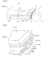
Fig. 11 is a perspective view showing a connection part between the battery pack and quick charging cables in the cable connecting structure of the battery pack according to the fourth embodiment. -
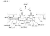
Fig. 12 is a view as seen in a direction of an arrow A inFig. 11 . - Now, embodiments according to the invention will be described referring to the drawings.
- In the following embodiments, a case where the vehicle to which the cable connecting structure of the battery pack according to the invention is applied is an electric motor car employing only a motor as a driving source will be described. However, the invention is not only applied to the electric motor car, but can be widely applied to other vehicles, provided that the battery pack is provided under floor. For example, the invention can be widely applied to electrically driven cars such as a hybrid car, a plug-in hybrid car, and so on.
- As shown in
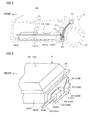
Fig. 1 , avehicle 10 includes avehicle body 12, a driving motor which is not shown, front wheels which are not shown,rear wheels 14, aquick charging port 16, a battery pack 18, battery pack side connectors 20 (20A, 20B), quick charging cables 22 (22A, 22B), and cable side connectors 24 (24A, 24B). - It is to be noted that this embodiment relates to a cable connecting structure of the battery pack 18 in which a plurality of the
cable side connectors 24 are connected to thequick charging port 16, which is an electrical component, at their one ends, and connected to the battery pack 18, at their other ends. - The
vehicle body 12 includes a pair of right and left side members, a plurality of cross members, and a floor panel which is provided above these side members and cross members, all of which are not shown. - The floor panel which is disposed in a lower part of the vehicle body is formed of steel sheet, and extended both in a longitudinal direction and in a lateral direction of the vehicle. Both sides in the lateral direction of a lower face of the floor panel are joined to the two side members by welding.
- The driving motor is disposed in a rear part of the
vehicle body 12, and actuated by an electric power which is supplied from the battery pack 18 via an inverter thereby to rotate therear wheels 14. - On occasion of externally charging the battery pack 18, a charging gun of a quick charging device, which is an external power supply, is attached to the
quick charging port 16 thereby to supply a high voltage electric power. Thisquick charging port 16 is provided with a positive terminal and a negative terminal, and in this embodiment, thisquick charging port 16 is an electrical component. - Moreover, the
quick charging port 16 is provided at a position above therear wheel 14 on a rearward left side face of thevehicle body 12. - The battery pack 18 is disposed below a floor panel 28 between a pair of the right and left side members, and includes a battery for driving, which is not shown, and a
battery case 18A which contains this battery. - The battery includes a plurality of battery modules which are connected to each other in series, and peripheral components for enabling these battery modules to function. Each of the battery modules includes a plurality of battery cells which are connected to each other in series.
- The
battery case 18A has a shape of a rectangular plate in a plan view, and is disposed in a center part in the lateral direction of the vehicle, having its longitudinal direction aligned with a longitudinal direction of thevehicle 10. - The
battery case 18A is disposed between a pair of the side members below the floor panel, and fitted to the two side members via a fitting member. - The
battery case 18A includes anupper wall 1802 directed upward, alower wall 1804 directed downward, and a peripheral wall 1805 which is directed in the longitudinal direction and the lateral direction of thevehicle 10, that is, in a direction perpendicular to the vertical direction, for connecting theupper wall 1802 and thelower wall 1804 to each other. - The peripheral wall 1805 includes a
front wall 1806 directed to a front side of the vehicle, and a rear wall 1808 directed to a rear side of the vehicle, aleft side wall 1810 directed to a left side in the lateral direction, and aright side wall 1812 directed to a right side in the lateral direction. - In this embodiment, a distance between the rear wall 1808 of the
battery case 18A and the tworear wheels 14 is small, because thevehicle 10 is a light-duty car or a compact car. - Moreover, components for mechanisms such as a suspension mechanism, a brake mechanism, and various wiring materials are provided between the two
rear wheels 14 which have a small distance between them. Therefore, there is a complicated space in rear of the rear wall 1808 of the battery pack 18. - As shown in
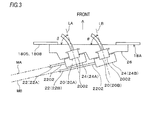
Figs. 2 and3 , the batterypack side connector 20 includes two battery pack sidequick charging connectors - The two battery pack side
quick charging connectors quick charging connectors - In this embodiment, the two battery pack side
quick charging connectors mounting bracket 26. - Moreover, in case where the
vehicle 10 is seen from the above, in a plan view, the two battery pack sidequick charging connectors - Further, the two battery pack side
quick charging connectors faces 2002 to which the cable sidequick charging connectors mounting faces 2002 are perpendicular to the axes LA, LB. - The
cable side connectors quick charging cables quick charging port 16 are detachably mounted to the two battery pack sidequick charging connectors - The two
quick charging cables - One of the two
quick charging cables port 16, and the other is a negative side quick charging cable which is connected to the negative terminal of the quick chargingport 16. - The two
quick charging cables - Specifically, the
cable side connector 24 includes the two cable sidequick charging connectors - The two cable side
quick charging connectors quick charging connectors quick charging connectors quick charging connectors portions 2202 of the twoquick charging cables quick charging connectors - In this embodiment, the cable side
quick charging connectors quick charging connectors respective portions 2202 of thequick charging cables quick charging connectors quick charging connectors 24. - Moreover, as shown in
Fig. 3 , in a state where the two cable sidequick charging connectors quick charging connectors portions 2202 of the twoquick charging cables quick charging connectors quick charging connectors quick charging connectors quick charging cables quick charging connectors - Moreover, in this embodiment, the
portions 2202 of thequick charging cables quick charging connectors quick charging connectors quick charging connectors - In this embodiment, in case where the
vehicle 10 is seen from the above in a plan view, as shown inFig. 3 , an inclination angle δ of the axis LA of the battery pack sidequick charging connector 20A which is close to the quick chargingport 16 with respect to the rear wall 1808, out of two battery pack sidequick charging connectors quick charging connector 20B which is remote from the quick chargingport 16 with respect to the rear wall 1808. Then, theportion 2202 of thequick charging cable 22B withdrawn from the cable sidequick charging connector 24B which is mounted to the battery pack sidequick charging connector 20B which is remote from the quick chargingport 16 is positioned more rearward of the vehicle than the cable sidequick charging connector 24A which is mounted to the battery pack sidequick charging connector 20A which is close to the quick chargingport 16, and theportion 2202 of thequick charging cable 22A withdrawn from theconnector 24A, so that theportion 2202 of thecable 22B may not interfere with theconnector 24A and thecable 22A. - Moreover, in case where the
vehicle 10 is seen in a side view, as shown inFig. 1 , the twoquick charging cables rear wheel 14. - Then, operation and effects will be described.
- According to this embodiment, the two cable side
quick charging connectors quick charging cables quick charging connectors 20 are provided on the rear wall 1808 in parallel with each other along the lateral direction of the vehicle which is the extending direction of the rear wall 1808. - Accordingly, as compared with a connector which is a single component to which the two
quick charging cables quick charging connectors quick charging connectors quick charging connectors - Because the two battery pack side
quick charging connectors - Moreover, according to this embodiment, the two cable side
quick charging connectors quick charging connectors quick charging connectors quick charging connectors portions 2202 of the twoquick charging cables quick charging connectors - Accordingly, the space required for wiring the two
quick charging cables quick charging cables - Moreover, according to this embodiment, in a state where the two cable side
quick charging connectors quick charging connectors respective portions 2202 of the twoquick charging cables quick charging connectors - Accordingly, the
quick charging cables quick charging cables - Further, according to this embodiment, the
respective portions 2202 of thequick charging cables quick charging connectors quick charging connectors quick charging connectors - Accordingly, it is possible to secure a space between the
quick charging cables quick charging cables - Moreover, according to this embodiment, the two cables are the
quick charging cables port 16, and the two battery pack sidequick charging connectors quick charging connectors vehicle 10, out of the peripheral wall 1805 of the battery pack 18. Further, in case where thevehicle 10 is seen in a side view, the twoquick charging cables rear wheel 14. - Therefore, although the space in the rear of the rear wall 1808 of the battery pack 18 is complicated, it is possible to wire the
quick charging cables quick charging cables - On the contrary, in case of withdrawing the
quick charging cables quick charging cables quick charging cables - Accordingly, in case where the
quick charging cables quick charging cables quick charging cables - Moreover, in this embodiment, the
quick charging cables quick charging cables quick charging cables vehicle 10 is collided from the rear side. As the results, protection of the battery pack 18 can be advantageously achieved. - Although in this embodiment, a case where the quick charging
port 16 is provided on thevehicle body 12 at a position rearward from the battery pack 18 has been described, it is also possible to provide the quick chargingport 16 on thevehicle body 12 at a position frontward from the battery pack 18. - In this case, the two battery pack side
quick charging connectors quick charging connectors quick charging cables front wall 1806 which is closer to the quick chargingport 16, out of a front face and a rear face of the peripheral wall 1805 of the battery pack 18. Moreover, in case where thevehicle 10 is seen in a side view, the twoquick charging cables - In the above described structure too, the wiring space for the
quick charging cables quick charging cables - Moreover, in case where the
vehicle 10 is collided from the front, the force applied to the battery pack 18 via thequick charging cables - Then, the second embodiment will be described referring to
Figs. 4 to 6 . - It is to be noted that in the following embodiments, the parts and members which are substantially same as those in the first embodiment are denoted with the same reference numerals, omitting their descriptions, and only different parts are mainly described.
- In the second embodiment too, in the same manner as in the first embodiment, the two battery pack side
quick charging connectors bracket 26, in parallel with each other in the lateral direction of the vehicle which is the extending direction of the rear wall 1808. - Moreover, as shown in
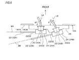
Fig. 6 , in a state where the two cable sidequick charging connectors quick charging connectors portions 2202 of thecables quick charging connectors quick charging connectors quick charging connectors cables quick charging connectors cables - Moreover, in a plan view, the axis LA of one of the battery pack side
quick charging connectors - Moreover, the
portion 2202 of the battery side quick chargingcable 22B withdrawn from the cable sidequick charging connector 24B which is mounted to the inclined battery pack sidequick charging connector 20B is so formed as to be separated from the rear wall 1808, as going away from the inclined battery pack sidequick charging connector 20B. - Moreover, one of mounting
faces 2002 of the battery pack sidequick charging connectors cable side connectors face 2002. - Specifically, the mounting
face 2002 of the battery pack sidequick charging connector 20B which is remote from the quick chargingport 16 is positioned more rearward of the battery pack 18 than the mountingface 2002 of the battery pack sidequick charging connector 20A which is close to the quick chargingport 16. - In this manner, the
portion 2202 of thequick charging cable 22B withdrawn from the cable sidequick charging connector 24B which is mounted to the battery pack sidequick charging connector 20B is positioned rearward of the vehicle than the cable sidequick charging connector 24A which is mounted to the battery pack sidequick charging connector 20A and theportion 2202 of thequick charging cable 22A withdrawn from the connector, so that theportion 2202 of thecable 22B may not interfere with theconnector 24A and thecable 22A. - Also in the second embodiment as described above, the substantially same advantage as in the first embodiment can be attained.
- Moreover, a larger space can be secured between the rear wall 1808 and the
portion 2202 of thequick charging cable 22B withdrawn from the cable sidequick charging connector 24B which is mounted to the battery pack sidequick charging connector 20B, which has the mountingface 2002 positioned outward of the battery pack 18, as compared with the other mountingface 2002. Therefore, a work for wiring thequick charging cable 22B along the rear wall 1808 can be advantageously conducted with high efficiency. - Then, the third embodiment will be described referring to
Figs. 7 to 9 . - In the third embodiment too, in the same manner as in the first embodiment, the two battery pack side
quick charging connectors bracket 26, in parallel with each other in the lateral direction of the vehicle which is the extending direction of the rear wall 1808. - Moreover, as shown in
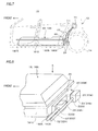
Fig. 9 , in a state where the two cable sidequick charging connectors quick charging connectors portions 2202 of thecables quick charging connectors quick charging connectors quick charging connectors cables quick charging connectors - In the third embodiment, axes of the battery pack side
quick charging connectors - Moreover, one of the mounting faces 2002 of the battery pack side
quick charging connectors cable side connectors face 2002. - Specifically, the mounting
face 2002 of the battery pack sidequick charging connector 20B which is remote from the quick chargingport 16 is positioned more rearward of the battery pack 18 than the mountingface 2002 of the battery pack sidequick charging connector 20A which is close to the quick chargingport 16. - In this manner, the
portion 2202 of thequick charging cable 22B withdrawn from the cable sidequick charging connector 24B which is mounted to the battery pack sidequick charging connector 20B is positioned more rearward of the vehicle than the cable sidequick charging connector 24A which is mounted to the battery pack sidequick charging connector 20A and theportion 2202 of thequick charging cable 22A withdrawn from the connector, so that theportion 2202 of thecable 22B may not interfere with theconnector 24A and thecable 22A. - Also in the third embodiment as described above, the substantially same advantage as in the first embodiment can be attained.
- Then, the fourth embodiment will be described referring to
Figs. 10 to 12 . - In the fourth embodiment too, in the same manner as in the first embodiment, the two battery pack side
quick charging connectors bracket 26, in parallel in the lateral direction of the vehicle which is the extending direction of the rear wall 1808. - In a state where the cable side
quick charging connectors quick charging connectors quick charging cables quick charging connectors - The axes of the two battery pack side
quick charging connectors pack side connectors vehicle 10. In other words, the mounting faces 2002 of the batterypack side connectors - Therefore, the battery pack side
quick charging connector 20B which is remote from the quick chargingport 16 and the battery pack sidequick charging connector 20A which is close to the quick chargingport 16 are provided on the same position in the longitudinal direction of thevehicle 10. - Then, the
portion 2202 of thequick charging cable 22B withdrawn from the cable sidequick charging connector 24B which is mounted to the battery pack sidequick charging connector 20B which is remote from the quick chargingport 16 is provided in a crooked manner, so as to extend along the rear wall 1808, passing below the cable sidequick charging connector 24A which is mounted to the battery pack sidequick charging connector 20A which is close to the quick chargingport 16. - In this manner, the
portion 2202 of thequick charging cable 22B withdrawn from the cable sidequick charging connector 24B which is mounted to the battery pack sidequick charging connector 20B is positioned lower than theportion 2202 of thequick charging cable 22A withdrawn from the cable sidequick charging connector 24A which is mounted to the battery pack sidequick charging connector 20A, so that theportion 2202 of thecable 22B may not interfere with theconnector 24A and thecable 22A. - Also in the fourth embodiment as described above, the substantially same advantage as in the first embodiment can be attained.
- Moreover, in the fourth embodiment, both the two battery pack side
quick charging connectors vehicle 10. Accordingly, a space in rear of the vehicle from the rear wall 1808 to be occupied by the two battery pack sidequick charging connectors quick charging connectors - In this embodiment, a case where the
cables cable side connectors pack side connectors - Moreover, these cables, cable side connectors, and battery side connectors need not be those for charging, but may be those for power supply. In this case, the cables are connected to an electrical component which is actuated by the power supplied from the battery pack 18.
- Moreover, although in this embodiment, a case where the battery pack side connectors are provided on the rear wall 1808 of the battery pack 18 has been described, it is of course possible to provide the battery
pack side connectors front wall 1806, the left andright side walls - According to an aspect of the invention, there is provided a cable connecting structure of a battery pack, the battery pack which is provided in a vehicle and to which a plurality of cables, which are respectively connected to an electrical component at one ends, are connected at the other ends, the cable connecting structure comprising: a plurality of cable side connectors which are provided at the other ends of the cables, and which are connected to the battery pack; and a plurality of battery pack side connectors to which the cable side connectors are detachably mounted, and which are arranged in parallel along a peripheral direction of a peripheral wall of the battery pack, wherein, in a state where the cable side connectors are mounted to the battery pack side connectors, portions of the cables which are respectively withdrawn from the cable side connectors extend along the peripheral wall.
- According to the above structure, the plurality of battery pack side connectors are arranged in parallel along the peripheral direction of the peripheral wall of the battery pack. Accordingly, as compared with a single connector to which a plurality of cables are connected, an outer size of the respective cable side connectors can be reduced, and also, an outer size of the battery pack side connectors to which these cable side connectors are mounted can be reduced. Because the battery pack side connectors having the small outer size are arranged in parallel along the peripheral direction of the peripheral wall, a height of the peripheral wall of the battery pack can be depressed, which is advantageous in making the battery pack compact.
- Moreover, in a state where the plurality of cable side connectors are mounted to the plurality of battery pack side connectors, the portions of the cables withdrawn from the cable side connectors extend along the peripheral wall. Accordingly, the space required for wiring a plurality of the cables is reduced to the minimum, and hence, the space required for providing these cables can be advantageously made compact.
- In a state where the cable side connectors are mounted to the battery pack side connectors, imaginary extensions of the portions of the cables which are respectively withdrawn from the cable side connectors which are adjacent to each other may not intersect with each other, in a plan view of the battery pack.
- In this structure, a wiring work of the cables which are unlikely to be bent, having high rigidity, can be advantageously conducted with high efficiency.
- At least one of the battery pack side connectors which are adjacent to each other may have an axis inclined with respect to the peripheral wall, in the plan view of the battery pack, and the portion of the cable withdrawn from the cable side connector which is mounted to the battery pack side connector the axis of which is inclined may be separated from the peripheral wall, as going away from the battery pack connector the axis of which is inclined.
- In this structure, a space can be secured between the peripheral wall and the portion of the cable withdrawn from the cable side connector which is mounted to the battery pack side connector, and hence, the work for wiring the cable along the peripheral wall can be advantageously conducted with high efficiency.
- The battery pack side connectors may have mounting faces to which the cable side connectors are mounted, and the mounting face of one of the battery pack side connectors which are adjacent to each other may be positioned more outward of the battery pack than the mounting face of the other battery pack side connector.
- In this structure, it is possible to secure a larger space between the peripheral wall and the portion of the cable withdrawn from the cable side connector which is mounted to the battery pack side connector, which has the mounting face positioned outward of the battery pack, as compared with the other mounting face. Therefore, the work for wiring the cable along the peripheral wall can be advantageously conducted with high efficiency.
- The electrical component may include a charging port which is provided on an outer face of the vehicle at a front side or at a rear side of the vehicle, and to which a charging gun which is connected to an external power supply is connected, when the battery pack is externally charged, at least two of the cables may be two cables respectively connected to a positive terminal and a negative terminal of the charging port, two battery pack side connectors to which the cable side connectors of the two cables are mounted may be disposed on one of a frontward face and a rearward face of the peripheral wall of the battery pack which is closer to the charging port, and the two cables may be so arranged as to pass between the battery pack and wheels of the vehicle, in case where the vehicle is seen in a side view.
- In this structure, in case where there is a complicated space in front or in rear of the peripheral wall of the battery pack, the wiring space for the cables can be made compact, by extending the cables along the peripheral wall. As the results, the wiring work of the cables in the complicated space can be omitted, and the cables can be easily wired advantageously. Moreover, when the vehicle is collided from the front side or the rear side, a force applied to the battery pack via the cables can be reduced, and as the results, protection of the battery pack can be advantageously achieved.
Claims (6)
- A cable connecting structure of a battery pack, the battery pack which is provided in a vehicle, the cable connecting structure comprising:a plurality of cable side connectors which are provided at ends of a plurality of cables, respectively, and which are connected to the battery pack; anda plurality of battery pack side connectors to which the cable side connectors are detachably mounted, and which are arranged in parallel along a peripheral direction of a peripheral wall of the battery pack, wherein,in a state where the cable side connectors are mounted to the battery pack side connectors, portions of the cables which are respectively withdrawn from the cable side connectors are extended along the peripheral wall.
- The cable connecting structure according to claim 1, wherein,
in a state where the cable side connectors are mounted to the battery pack side connectors, the cables are extended from the cable side connectors, respectively, so as to be parallel to each other, or are extended from the cable side connectors in a direction in which the cables are separated from each other. - The cable connecting structure according to claim 2, wherein
at least one of the battery pack side connectors which are adjacent to each other has an axis inclined with respect to the peripheral wall, in a plan view of the battery pack, and
the portion of the cable withdrawn from the cable side connector which is mounted to the battery pack side connector the axis of which is inclined is separated from the peripheral wall, as going away from the battery pack connector the axis of which is inclined. - The cable connecting structure according to claim 2, wherein
the battery pack side connectors have mounting faces to which the cable side connectors are mounted, and
the mounting face of one of the battery pack side connectors which are adjacent to each other is positioned more outward of the battery pack than the mounting face of the other battery pack side connector. - The cable connecting structure according to claim 2, wherein,
the battery pack side connectors have mounting faces to which the cable side connectors are mounted, and
at least two of the mounting faces of the battery pack side connectors have the same height from the peripheral wall of the battery pack. - The cable connecting structure according to any one of claims 1 to 5, wherein
at least two of the cables are respectively connected to a positive terminal and a negative terminal of a charging port of the vehicle which is connected to an external power supply, and
two battery pack side connectors to which the cable side connectors of the at least two cables are mounted are disposed on one of a frontward face and a rearward face of the peripheral wall of the battery pack which is closer to the charging port.
Applications Claiming Priority (1)
| Application Number | Priority Date | Filing Date | Title |
|---|---|---|---|
| JP2014138326A JP6361329B2 (en) | 2014-07-04 | 2014-07-04 | Battery pack cable connection structure |
Publications (2)
| Publication Number | Publication Date |
|---|---|
| EP2962882A1 true EP2962882A1 (en) | 2016-01-06 |
| EP2962882B1 EP2962882B1 (en) | 2020-01-22 |
Family
ID=53510762
Family Applications (1)
| Application Number | Title | Priority Date | Filing Date |
|---|---|---|---|
| EP15175212.8A Active EP2962882B1 (en) | 2014-07-04 | 2015-07-03 | Cable connecting structure of battery pack |
Country Status (4)
| Country | Link |
|---|---|
| US (1) | US9531091B2 (en) |
| EP (1) | EP2962882B1 (en) |
| JP (1) | JP6361329B2 (en) |
| CN (1) | CN105235487B (en) |
Families Citing this family (9)
| Publication number | Priority date | Publication date | Assignee | Title |
|---|---|---|---|---|
| DE102014200290A1 (en) * | 2014-01-10 | 2015-07-16 | Robert Bosch Gmbh | Electric charging device, electrical connection device, system and method for charging a battery of a vehicle |
| JP6361329B2 (en) * | 2014-07-04 | 2018-07-25 | 三菱自動車工業株式会社 | Battery pack cable connection structure |
| KR102085344B1 (en) * | 2016-10-24 | 2020-04-23 | 주식회사 엘지화학 | Battery pack for a vehicle and Vehicle including the same |
| US11367918B2 (en) * | 2018-11-13 | 2022-06-21 | Rivian Ip Holdings, Llc | Electric vehicle battery pack having external side pouch for electrical components |
| JP7062603B2 (en) * | 2019-02-05 | 2022-05-06 | 本田技研工業株式会社 | Power storage device |
| JP7363602B2 (en) | 2020-03-11 | 2023-10-18 | スズキ株式会社 | Vehicle battery mounting structure |
| JP7189904B2 (en) * | 2020-03-18 | 2022-12-14 | 矢崎総業株式会社 | Connection structure of electric junction box |
| JP7353241B2 (en) * | 2020-06-22 | 2023-09-29 | 本田技研工業株式会社 | vehicle |
| JP7502720B2 (en) | 2020-12-28 | 2024-06-19 | スズキ株式会社 | Vehicle battery pack peripheral structure |
Citations (4)
| Publication number | Priority date | Publication date | Assignee | Title |
|---|---|---|---|---|
| US20130256046A1 (en) * | 2012-03-30 | 2013-10-03 | Honda Motor Co., Ltd. | Low-slung electric vehicle |
| JP2013251111A (en) | 2012-05-31 | 2013-12-12 | Mitsubishi Motors Corp | Battery case |
| WO2014002537A1 (en) * | 2012-06-29 | 2014-01-03 | 三菱自動車工業株式会社 | Electric vehicle |
| WO2014034377A1 (en) * | 2012-08-27 | 2014-03-06 | 日産自動車株式会社 | High-voltage harness connection structure for electric vehicle |
Family Cites Families (6)
| Publication number | Priority date | Publication date | Assignee | Title |
|---|---|---|---|---|
| JP5170867B2 (en) * | 2007-10-26 | 2013-03-27 | プライムアースEvエナジー株式会社 | Battery assembly and connection cable |
| CN102958789B (en) * | 2010-09-30 | 2015-04-29 | 本田技研工业株式会社 | Scooter-type electric vehicle |
| KR101506410B1 (en) * | 2010-11-19 | 2015-03-26 | 혼다 기켄 고교 가부시키가이샤 | Electric saddled vehicle, and drive device for electric vehicle |
| JP5803259B2 (en) * | 2011-05-17 | 2015-11-04 | 日産自動車株式会社 | Battery pack structure for electric vehicles |
| JP5468594B2 (en) * | 2011-11-14 | 2014-04-09 | 本田技研工業株式会社 | Electric vehicle power supply device |
| JP6361329B2 (en) * | 2014-07-04 | 2018-07-25 | 三菱自動車工業株式会社 | Battery pack cable connection structure |
-
2014
- 2014-07-04 JP JP2014138326A patent/JP6361329B2/en active Active
-
2015
- 2015-07-02 US US14/790,869 patent/US9531091B2/en active Active
- 2015-07-03 EP EP15175212.8A patent/EP2962882B1/en active Active
- 2015-07-06 CN CN201510391193.2A patent/CN105235487B/en active Active
Patent Citations (4)
| Publication number | Priority date | Publication date | Assignee | Title |
|---|---|---|---|---|
| US20130256046A1 (en) * | 2012-03-30 | 2013-10-03 | Honda Motor Co., Ltd. | Low-slung electric vehicle |
| JP2013251111A (en) | 2012-05-31 | 2013-12-12 | Mitsubishi Motors Corp | Battery case |
| WO2014002537A1 (en) * | 2012-06-29 | 2014-01-03 | 三菱自動車工業株式会社 | Electric vehicle |
| WO2014034377A1 (en) * | 2012-08-27 | 2014-03-06 | 日産自動車株式会社 | High-voltage harness connection structure for electric vehicle |
Also Published As
| Publication number | Publication date |
|---|---|
| JP6361329B2 (en) | 2018-07-25 |
| JP2016018590A (en) | 2016-02-01 |
| US9531091B2 (en) | 2016-12-27 |
| US20160006147A1 (en) | 2016-01-07 |
| CN105235487A (en) | 2016-01-13 |
| CN105235487B (en) | 2018-04-13 |
| EP2962882B1 (en) | 2020-01-22 |
Similar Documents
| Publication | Publication Date | Title |
|---|---|---|
| EP2962882B1 (en) | Cable connecting structure of battery pack | |
| CN104868073B (en) | Vehicle battery | |
| JP5776852B2 (en) | High-voltage harness connection structure for electric vehicles | |
| JP6094060B2 (en) | Battery case | |
| JP6222178B2 (en) | Electric vehicle | |
| WO2012157316A1 (en) | Charging/discharging harness routing structure for electric automobile | |
| CN108367660B (en) | Mounting structure of high-voltage control device unit | |
| JP5935988B2 (en) | Vehicle power supply system | |
| KR101757554B1 (en) | Electric equipment unit and vehicle | |
| US20190255928A1 (en) | Traction battery | |
| JP6817248B2 (en) | Arrangement structure of electrical equipment in electric vehicles | |
| JP5874563B2 (en) | Connector structure for electric vehicles | |
| CN110893757B (en) | Vehicle with a steering wheel | |
| JP2021079765A (en) | On-vehicle structure of electric power converter | |
| JP6981228B2 (en) | Power control unit mounting structure | |
| WO2011145577A1 (en) | Protection structure for high-voltage unit | |
| JP6520190B2 (en) | Wiring structure of vehicle harness | |
| WO2013133151A1 (en) | Electric automobile harness routing structure | |
| WO2020137472A1 (en) | Wire harness assembly and wire harness assembly mounting structure | |
| JP2016179798A (en) | In-vehicle battery | |
| JP6394200B2 (en) | Electricity storage pack | |
| JP7172901B2 (en) | power storage device | |
| JP7435546B2 (en) | In-vehicle electrical equipment | |
| JP2019151159A (en) | Electric power unit | |
| WO2020137471A1 (en) | Power supply device and vehicle |
Legal Events
| Date | Code | Title | Description |
|---|---|---|---|
| PUAI | Public reference made under article 153(3) epc to a published international application that has entered the european phase |
Free format text: ORIGINAL CODE: 0009012 |
|
| AK | Designated contracting states |
Kind code of ref document: A1 Designated state(s): AL AT BE BG CH CY CZ DE DK EE ES FI FR GB GR HR HU IE IS IT LI LT LU LV MC MK MT NL NO PL PT RO RS SE SI SK SM TR |
|
| AX | Request for extension of the european patent |
Extension state: BA ME |
|
| 17P | Request for examination filed |
Effective date: 20160706 |
|
| RBV | Designated contracting states (corrected) |
Designated state(s): AL AT BE BG CH CY CZ DE DK EE ES FI FR GB GR HR HU IE IS IT LI LT LU LV MC MK MT NL NO PL PT RO RS SE SI SK SM TR |
|
| RAP1 | Party data changed (applicant data changed or rights of an application transferred) |
Owner name: MITSUBISHI JIDOSHA KOGYO KABUSHIKI KAISHA |
|
| RIC1 | Information provided on ipc code assigned before grant |
Ipc: B60L 50/64 20190101ALI20190725BHEP Ipc: H01M 2/10 20060101ALI20190725BHEP Ipc: B60L 50/60 20190101ALI20190725BHEP Ipc: B60R 16/02 20060101ALI20190725BHEP Ipc: B60L 53/10 20190101ALI20190725BHEP Ipc: B60K 1/04 20190101AFI20190725BHEP Ipc: B60L 53/14 20190101ALI20190725BHEP |
|
| GRAP | Despatch of communication of intention to grant a patent |
Free format text: ORIGINAL CODE: EPIDOSNIGR1 |
|
| STAA | Information on the status of an ep patent application or granted ep patent |
Free format text: STATUS: GRANT OF PATENT IS INTENDED |
|
| INTG | Intention to grant announced |
Effective date: 20190927 |
|
| GRAS | Grant fee paid |
Free format text: ORIGINAL CODE: EPIDOSNIGR3 |
|
| GRAA | (expected) grant |
Free format text: ORIGINAL CODE: 0009210 |
|
| STAA | Information on the status of an ep patent application or granted ep patent |
Free format text: STATUS: THE PATENT HAS BEEN GRANTED |
|
| AK | Designated contracting states |
Kind code of ref document: B1 Designated state(s): AL AT BE BG CH CY CZ DE DK EE ES FI FR GB GR HR HU IE IS IT LI LT LU LV MC MK MT NL NO PL PT RO RS SE SI SK SM TR |
|
| REG | Reference to a national code |
Ref country code: GB Ref legal event code: FG4D |
|
| REG | Reference to a national code |
Ref country code: CH Ref legal event code: EP |
|
| REG | Reference to a national code |
Ref country code: AT Ref legal event code: REF Ref document number: 1226697 Country of ref document: AT Kind code of ref document: T Effective date: 20200215 |
|
| REG | Reference to a national code |
Ref country code: IE Ref legal event code: FG4D |
|
| REG | Reference to a national code |
Ref country code: DE Ref legal event code: R096 Ref document number: 602015045878 Country of ref document: DE |
|
| REG | Reference to a national code |
Ref country code: NL Ref legal event code: MP Effective date: 20200122 |
|
| REG | Reference to a national code |
Ref country code: LT Ref legal event code: MG4D |
|
| PG25 | Lapsed in a contracting state [announced via postgrant information from national office to epo] |
Ref country code: FI Free format text: LAPSE BECAUSE OF FAILURE TO SUBMIT A TRANSLATION OF THE DESCRIPTION OR TO PAY THE FEE WITHIN THE PRESCRIBED TIME-LIMIT Effective date: 20200122 Ref country code: RS Free format text: LAPSE BECAUSE OF FAILURE TO SUBMIT A TRANSLATION OF THE DESCRIPTION OR TO PAY THE FEE WITHIN THE PRESCRIBED TIME-LIMIT Effective date: 20200122 Ref country code: NL Free format text: LAPSE BECAUSE OF FAILURE TO SUBMIT A TRANSLATION OF THE DESCRIPTION OR TO PAY THE FEE WITHIN THE PRESCRIBED TIME-LIMIT Effective date: 20200122 Ref country code: PT Free format text: LAPSE BECAUSE OF FAILURE TO SUBMIT A TRANSLATION OF THE DESCRIPTION OR TO PAY THE FEE WITHIN THE PRESCRIBED TIME-LIMIT Effective date: 20200614 Ref country code: NO Free format text: LAPSE BECAUSE OF FAILURE TO SUBMIT A TRANSLATION OF THE DESCRIPTION OR TO PAY THE FEE WITHIN THE PRESCRIBED TIME-LIMIT Effective date: 20200422 |
|
| PG25 | Lapsed in a contracting state [announced via postgrant information from national office to epo] |
Ref country code: BG Free format text: LAPSE BECAUSE OF FAILURE TO SUBMIT A TRANSLATION OF THE DESCRIPTION OR TO PAY THE FEE WITHIN THE PRESCRIBED TIME-LIMIT Effective date: 20200422 Ref country code: IS Free format text: LAPSE BECAUSE OF FAILURE TO SUBMIT A TRANSLATION OF THE DESCRIPTION OR TO PAY THE FEE WITHIN THE PRESCRIBED TIME-LIMIT Effective date: 20200522 Ref country code: GR Free format text: LAPSE BECAUSE OF FAILURE TO SUBMIT A TRANSLATION OF THE DESCRIPTION OR TO PAY THE FEE WITHIN THE PRESCRIBED TIME-LIMIT Effective date: 20200423 Ref country code: SE Free format text: LAPSE BECAUSE OF FAILURE TO SUBMIT A TRANSLATION OF THE DESCRIPTION OR TO PAY THE FEE WITHIN THE PRESCRIBED TIME-LIMIT Effective date: 20200122 Ref country code: LV Free format text: LAPSE BECAUSE OF FAILURE TO SUBMIT A TRANSLATION OF THE DESCRIPTION OR TO PAY THE FEE WITHIN THE PRESCRIBED TIME-LIMIT Effective date: 20200122 Ref country code: HR Free format text: LAPSE BECAUSE OF FAILURE TO SUBMIT A TRANSLATION OF THE DESCRIPTION OR TO PAY THE FEE WITHIN THE PRESCRIBED TIME-LIMIT Effective date: 20200122 |
|
| REG | Reference to a national code |
Ref country code: DE Ref legal event code: R097 Ref document number: 602015045878 Country of ref document: DE |
|
| PG25 | Lapsed in a contracting state [announced via postgrant information from national office to epo] |
Ref country code: SK Free format text: LAPSE BECAUSE OF FAILURE TO SUBMIT A TRANSLATION OF THE DESCRIPTION OR TO PAY THE FEE WITHIN THE PRESCRIBED TIME-LIMIT Effective date: 20200122 Ref country code: ES Free format text: LAPSE BECAUSE OF FAILURE TO SUBMIT A TRANSLATION OF THE DESCRIPTION OR TO PAY THE FEE WITHIN THE PRESCRIBED TIME-LIMIT Effective date: 20200122 Ref country code: LT Free format text: LAPSE BECAUSE OF FAILURE TO SUBMIT A TRANSLATION OF THE DESCRIPTION OR TO PAY THE FEE WITHIN THE PRESCRIBED TIME-LIMIT Effective date: 20200122 Ref country code: DK Free format text: LAPSE BECAUSE OF FAILURE TO SUBMIT A TRANSLATION OF THE DESCRIPTION OR TO PAY THE FEE WITHIN THE PRESCRIBED TIME-LIMIT Effective date: 20200122 Ref country code: EE Free format text: LAPSE BECAUSE OF FAILURE TO SUBMIT A TRANSLATION OF THE DESCRIPTION OR TO PAY THE FEE WITHIN THE PRESCRIBED TIME-LIMIT Effective date: 20200122 Ref country code: SM Free format text: LAPSE BECAUSE OF FAILURE TO SUBMIT A TRANSLATION OF THE DESCRIPTION OR TO PAY THE FEE WITHIN THE PRESCRIBED TIME-LIMIT Effective date: 20200122 Ref country code: CZ Free format text: LAPSE BECAUSE OF FAILURE TO SUBMIT A TRANSLATION OF THE DESCRIPTION OR TO PAY THE FEE WITHIN THE PRESCRIBED TIME-LIMIT Effective date: 20200122 Ref country code: RO Free format text: LAPSE BECAUSE OF FAILURE TO SUBMIT A TRANSLATION OF THE DESCRIPTION OR TO PAY THE FEE WITHIN THE PRESCRIBED TIME-LIMIT Effective date: 20200122 |
|
| REG | Reference to a national code |
Ref country code: AT Ref legal event code: MK05 Ref document number: 1226697 Country of ref document: AT Kind code of ref document: T Effective date: 20200122 |
|
| PLBE | No opposition filed within time limit |
Free format text: ORIGINAL CODE: 0009261 |
|
| STAA | Information on the status of an ep patent application or granted ep patent |
Free format text: STATUS: NO OPPOSITION FILED WITHIN TIME LIMIT |
|
| 26N | No opposition filed |
Effective date: 20201023 |
|
| PG25 | Lapsed in a contracting state [announced via postgrant information from national office to epo] |
Ref country code: IT Free format text: LAPSE BECAUSE OF FAILURE TO SUBMIT A TRANSLATION OF THE DESCRIPTION OR TO PAY THE FEE WITHIN THE PRESCRIBED TIME-LIMIT Effective date: 20200122 Ref country code: AT Free format text: LAPSE BECAUSE OF FAILURE TO SUBMIT A TRANSLATION OF THE DESCRIPTION OR TO PAY THE FEE WITHIN THE PRESCRIBED TIME-LIMIT Effective date: 20200122 |
|
| PG25 | Lapsed in a contracting state [announced via postgrant information from national office to epo] |
Ref country code: SI Free format text: LAPSE BECAUSE OF FAILURE TO SUBMIT A TRANSLATION OF THE DESCRIPTION OR TO PAY THE FEE WITHIN THE PRESCRIBED TIME-LIMIT Effective date: 20200122 Ref country code: PL Free format text: LAPSE BECAUSE OF FAILURE TO SUBMIT A TRANSLATION OF THE DESCRIPTION OR TO PAY THE FEE WITHIN THE PRESCRIBED TIME-LIMIT Effective date: 20200122 Ref country code: MC Free format text: LAPSE BECAUSE OF FAILURE TO SUBMIT A TRANSLATION OF THE DESCRIPTION OR TO PAY THE FEE WITHIN THE PRESCRIBED TIME-LIMIT Effective date: 20200122 |
|
| REG | Reference to a national code |
Ref country code: CH Ref legal event code: PL |
|
| GBPC | Gb: european patent ceased through non-payment of renewal fee |
Effective date: 20200703 |
|
| REG | Reference to a national code |
Ref country code: BE Ref legal event code: MM Effective date: 20200731 |
|
| PG25 | Lapsed in a contracting state [announced via postgrant information from national office to epo] |
Ref country code: LI Free format text: LAPSE BECAUSE OF NON-PAYMENT OF DUE FEES Effective date: 20200731 Ref country code: LU Free format text: LAPSE BECAUSE OF NON-PAYMENT OF DUE FEES Effective date: 20200703 Ref country code: GB Free format text: LAPSE BECAUSE OF NON-PAYMENT OF DUE FEES Effective date: 20200703 Ref country code: IE Free format text: LAPSE BECAUSE OF NON-PAYMENT OF DUE FEES Effective date: 20200703 Ref country code: CH Free format text: LAPSE BECAUSE OF NON-PAYMENT OF DUE FEES Effective date: 20200731 |
|
| PG25 | Lapsed in a contracting state [announced via postgrant information from national office to epo] |
Ref country code: BE Free format text: LAPSE BECAUSE OF NON-PAYMENT OF DUE FEES Effective date: 20200731 |
|
| PG25 | Lapsed in a contracting state [announced via postgrant information from national office to epo] |
Ref country code: TR Free format text: LAPSE BECAUSE OF FAILURE TO SUBMIT A TRANSLATION OF THE DESCRIPTION OR TO PAY THE FEE WITHIN THE PRESCRIBED TIME-LIMIT Effective date: 20200122 Ref country code: MT Free format text: LAPSE BECAUSE OF FAILURE TO SUBMIT A TRANSLATION OF THE DESCRIPTION OR TO PAY THE FEE WITHIN THE PRESCRIBED TIME-LIMIT Effective date: 20200122 Ref country code: CY Free format text: LAPSE BECAUSE OF FAILURE TO SUBMIT A TRANSLATION OF THE DESCRIPTION OR TO PAY THE FEE WITHIN THE PRESCRIBED TIME-LIMIT Effective date: 20200122 |
|
| PG25 | Lapsed in a contracting state [announced via postgrant information from national office to epo] |
Ref country code: MK Free format text: LAPSE BECAUSE OF FAILURE TO SUBMIT A TRANSLATION OF THE DESCRIPTION OR TO PAY THE FEE WITHIN THE PRESCRIBED TIME-LIMIT Effective date: 20200122 Ref country code: AL Free format text: LAPSE BECAUSE OF FAILURE TO SUBMIT A TRANSLATION OF THE DESCRIPTION OR TO PAY THE FEE WITHIN THE PRESCRIBED TIME-LIMIT Effective date: 20200122 |
|
| PGFP | Annual fee paid to national office [announced via postgrant information from national office to epo] |
Ref country code: DE Payment date: 20230531 Year of fee payment: 9 |
|
| PGFP | Annual fee paid to national office [announced via postgrant information from national office to epo] |
Ref country code: FR Payment date: 20240611 Year of fee payment: 10 |