WO2014002942A1 - 処理装置および画像形成装置 - Google Patents
処理装置および画像形成装置 Download PDFInfo
- Publication number
- WO2014002942A1 WO2014002942A1 PCT/JP2013/067236 JP2013067236W WO2014002942A1 WO 2014002942 A1 WO2014002942 A1 WO 2014002942A1 JP 2013067236 W JP2013067236 W JP 2013067236W WO 2014002942 A1 WO2014002942 A1 WO 2014002942A1
- Authority
- WO
- WIPO (PCT)
- Prior art keywords
- processing unit
- main body
- processing
- image forming
- apparatus main
- Prior art date
- Legal status (The legal status is an assumption and is not a legal conclusion. Google has not performed a legal analysis and makes no representation as to the accuracy of the status listed.)
- Ceased
Links
Images





Classifications
-
- B—PERFORMING OPERATIONS; TRANSPORTING
- B65—CONVEYING; PACKING; STORING; HANDLING THIN OR FILAMENTARY MATERIAL
- B65H—HANDLING THIN OR FILAMENTARY MATERIAL, e.g. SHEETS, WEBS, CABLES
- B65H31/00—Pile receivers
- B65H31/22—Pile receivers removable or interchangeable
-
- B—PERFORMING OPERATIONS; TRANSPORTING
- B65—CONVEYING; PACKING; STORING; HANDLING THIN OR FILAMENTARY MATERIAL
- B65H—HANDLING THIN OR FILAMENTARY MATERIAL, e.g. SHEETS, WEBS, CABLES
- B65H1/00—Supports or magazines for piles from which articles are to be separated
- B65H1/04—Supports or magazines for piles from which articles are to be separated adapted to support articles substantially horizontally, e.g. for separation from top of pile
-
- B—PERFORMING OPERATIONS; TRANSPORTING
- B65—CONVEYING; PACKING; STORING; HANDLING THIN OR FILAMENTARY MATERIAL
- B65H—HANDLING THIN OR FILAMENTARY MATERIAL, e.g. SHEETS, WEBS, CABLES
- B65H1/00—Supports or magazines for piles from which articles are to be separated
- B65H1/26—Supports or magazines for piles from which articles are to be separated with auxiliary supports to facilitate introduction or renewal of the pile
- B65H1/266—Support fully or partially removable from the handling machine, e.g. cassette, drawer
-
- B—PERFORMING OPERATIONS; TRANSPORTING
- B65—CONVEYING; PACKING; STORING; HANDLING THIN OR FILAMENTARY MATERIAL
- B65H—HANDLING THIN OR FILAMENTARY MATERIAL, e.g. SHEETS, WEBS, CABLES
- B65H1/00—Supports or magazines for piles from which articles are to be separated
- B65H1/28—Supports or magazines for piles from which articles are to be separated compartmented to receive piles side-by-side
-
- B—PERFORMING OPERATIONS; TRANSPORTING
- B65—CONVEYING; PACKING; STORING; HANDLING THIN OR FILAMENTARY MATERIAL
- B65H—HANDLING THIN OR FILAMENTARY MATERIAL, e.g. SHEETS, WEBS, CABLES
- B65H31/00—Pile receivers
-
- B—PERFORMING OPERATIONS; TRANSPORTING
- B65—CONVEYING; PACKING; STORING; HANDLING THIN OR FILAMENTARY MATERIAL
- B65H—HANDLING THIN OR FILAMENTARY MATERIAL, e.g. SHEETS, WEBS, CABLES
- B65H37/00—Article or web delivery apparatus incorporating devices for performing specified auxiliary operations
-
- B—PERFORMING OPERATIONS; TRANSPORTING
- B65—CONVEYING; PACKING; STORING; HANDLING THIN OR FILAMENTARY MATERIAL
- B65H—HANDLING THIN OR FILAMENTARY MATERIAL, e.g. SHEETS, WEBS, CABLES
- B65H5/00—Feeding articles separated from piles; Feeding articles to machines
- B65H5/06—Feeding articles separated from piles; Feeding articles to machines by rollers or balls, e.g. between rollers
- B65H5/062—Feeding articles separated from piles; Feeding articles to machines by rollers or balls, e.g. between rollers between rollers or balls
-
- G—PHYSICS
- G03—PHOTOGRAPHY; CINEMATOGRAPHY; ANALOGOUS TECHNIQUES USING WAVES OTHER THAN OPTICAL WAVES; ELECTROGRAPHY; HOLOGRAPHY
- G03G—ELECTROGRAPHY; ELECTROPHOTOGRAPHY; MAGNETOGRAPHY
- G03G21/00—Arrangements not provided for by groups G03G13/00 - G03G19/00, e.g. cleaning, elimination of residual charge
- G03G21/16—Mechanical means for facilitating the maintenance of the apparatus, e.g. modular arrangements
- G03G21/1604—Arrangement or disposition of the entire apparatus
-
- G—PHYSICS
- G03—PHOTOGRAPHY; CINEMATOGRAPHY; ANALOGOUS TECHNIQUES USING WAVES OTHER THAN OPTICAL WAVES; ELECTROGRAPHY; HOLOGRAPHY
- G03G—ELECTROGRAPHY; ELECTROPHOTOGRAPHY; MAGNETOGRAPHY
- G03G21/00—Arrangements not provided for by groups G03G13/00 - G03G19/00, e.g. cleaning, elimination of residual charge
- G03G21/16—Mechanical means for facilitating the maintenance of the apparatus, e.g. modular arrangements
- G03G21/1604—Arrangement or disposition of the entire apparatus
- G03G21/1619—Frame structures
-
- G—PHYSICS
- G03—PHOTOGRAPHY; CINEMATOGRAPHY; ANALOGOUS TECHNIQUES USING WAVES OTHER THAN OPTICAL WAVES; ELECTROGRAPHY; HOLOGRAPHY
- G03G—ELECTROGRAPHY; ELECTROPHOTOGRAPHY; MAGNETOGRAPHY
- G03G21/00—Arrangements not provided for by groups G03G13/00 - G03G19/00, e.g. cleaning, elimination of residual charge
- G03G21/16—Mechanical means for facilitating the maintenance of the apparatus, e.g. modular arrangements
- G03G21/1642—Mechanical means for facilitating the maintenance of the apparatus, e.g. modular arrangements for connecting the different parts of the apparatus
- G03G21/1647—Mechanical connection means
-
- H—ELECTRICITY
- H04—ELECTRIC COMMUNICATION TECHNIQUE
- H04N—PICTORIAL COMMUNICATION, e.g. TELEVISION
- H04N1/00—Scanning, transmission or reproduction of documents or the like, e.g. facsimile transmission; Details thereof
- H04N1/00002—Diagnosis, testing or measuring; Detecting, analysing or monitoring not otherwise provided for
- H04N1/00007—Diagnosis, testing or measuring; Detecting, analysing or monitoring not otherwise provided for relating to particular apparatus or devices
- H04N1/00013—Reading apparatus
-
- H—ELECTRICITY
- H04—ELECTRIC COMMUNICATION TECHNIQUE
- H04N—PICTORIAL COMMUNICATION, e.g. TELEVISION
- H04N1/00—Scanning, transmission or reproduction of documents or the like, e.g. facsimile transmission; Details thereof
- H04N1/00519—Constructional details not otherwise provided for, e.g. housings, covers
- H04N1/00551—Top covers or the like
- H04N1/00554—Latches or hinges therefor
-
- H—ELECTRICITY
- H04—ELECTRIC COMMUNICATION TECHNIQUE
- H04N—PICTORIAL COMMUNICATION, e.g. TELEVISION
- H04N1/00—Scanning, transmission or reproduction of documents or the like, e.g. facsimile transmission; Details thereof
- H04N1/00567—Handling of original or reproduction media, e.g. cutting, separating, stacking
- H04N1/0057—Conveying sheets before or after scanning
-
- H—ELECTRICITY
- H04—ELECTRIC COMMUNICATION TECHNIQUE
- H04N—PICTORIAL COMMUNICATION, e.g. TELEVISION
- H04N1/00—Scanning, transmission or reproduction of documents or the like, e.g. facsimile transmission; Details thereof
- H04N1/00567—Handling of original or reproduction media, e.g. cutting, separating, stacking
- H04N1/0057—Conveying sheets before or after scanning
- H04N1/00599—Using specific components
- H04N1/00604—Transport trays
-
- B—PERFORMING OPERATIONS; TRANSPORTING
- B65—CONVEYING; PACKING; STORING; HANDLING THIN OR FILAMENTARY MATERIAL
- B65H—HANDLING THIN OR FILAMENTARY MATERIAL, e.g. SHEETS, WEBS, CABLES
- B65H2402/00—Constructional details of the handling apparatus
- B65H2402/30—Supports; Subassemblies; Mountings thereof
- B65H2402/32—Sliding support means
-
- B—PERFORMING OPERATIONS; TRANSPORTING
- B65—CONVEYING; PACKING; STORING; HANDLING THIN OR FILAMENTARY MATERIAL
- B65H—HANDLING THIN OR FILAMENTARY MATERIAL, e.g. SHEETS, WEBS, CABLES
- B65H2402/00—Constructional details of the handling apparatus
- B65H2402/40—Details of frames, housings or mountings of the whole handling apparatus
- B65H2402/45—Doors
-
- B—PERFORMING OPERATIONS; TRANSPORTING
- B65—CONVEYING; PACKING; STORING; HANDLING THIN OR FILAMENTARY MATERIAL
- B65H—HANDLING THIN OR FILAMENTARY MATERIAL, e.g. SHEETS, WEBS, CABLES
- B65H2405/00—Parts for holding the handled material
- B65H2405/10—Cassettes, holders, bins, decks, trays, supports or magazines for sheets stacked substantially horizontally
- B65H2405/11—Parts and details thereof
- B65H2405/111—Bottom
- B65H2405/1117—Bottom pivotable, e.g. around an axis perpendicular to transport direction, e.g. arranged at rear side of sheet support
- B65H2405/11172—Bottom pivotable, e.g. around an axis perpendicular to transport direction, e.g. arranged at rear side of sheet support around an axis perpendicular to both transport direction and surface of sheets
-
- B—PERFORMING OPERATIONS; TRANSPORTING
- B65—CONVEYING; PACKING; STORING; HANDLING THIN OR FILAMENTARY MATERIAL
- B65H—HANDLING THIN OR FILAMENTARY MATERIAL, e.g. SHEETS, WEBS, CABLES
- B65H2801/00—Application field
- B65H2801/03—Image reproduction devices
- B65H2801/06—Office-type machines, e.g. photocopiers
Definitions
- the present invention relates to a processing apparatus having a first processing unit and a second processing unit disposed on a side surface of an apparatus main body that performs image forming processing on paper, and an image forming apparatus including the processing apparatus.
- some image forming apparatuses include a processing apparatus having a plurality of processing units for expanding functions in addition to an apparatus main body that performs image forming processing on paper.
- the processing unit includes a paper feeding device that accommodates a large volume of paper to be supplied to the apparatus main body, and a post-processing apparatus that performs post-processing on the paper on which image forming processing has been performed in the apparatus main body.
- the first processing unit and the second processing unit are provided on the opposite side surfaces of the apparatus main body, the installation area of the image forming apparatus increases.
- an image forming apparatus having a paper discharge tray on a paper feed tray is known (for example, see Patent Document 1).
- the paper feed tray and the paper discharge tray are provided one above the other so that the paper feed tray and the paper discharge tray are installed on different sides of the apparatus main body. The area is reduced.
- the paper feed tray and the paper discharge tray cannot be slid in the contact / separation direction with respect to the apparatus main body, so that the paper fed or discharged is poorly conveyed at the connection with the apparatus main body. When this occurs, it is difficult to perform maintenance such as removal of paper.
- the objects that are arranged one above the other on the same side of the apparatus main body are light and simple members such as a paper feed tray and a paper discharge tray, and not a processing unit.
- the paper feed tray and the paper discharge tray are configured to be rotatable.
- the paper feed tray and the paper discharge tray are lightweight, and is similar to a processing unit having a relatively large mass. It is difficult to apply this configuration. For this reason, it is difficult to maintain the processing unit with the configuration of the conventional image forming apparatus.
- An object of the present invention is to provide a processing apparatus capable of reducing an installation area and easily maintaining a processing unit provided on a side surface of the apparatus main body, and an image forming apparatus including the processing apparatus.
- the processing apparatus of the present invention includes a first processing unit and a second processing unit.
- the first processing unit and the second processing unit are arranged so as to overlap each other on the same side surface of the apparatus main body that performs image forming processing on a sheet.
- the second processing unit is disposed on the first processing unit and is configured to be slidable in the direction of separation from the apparatus main body.
- An image forming apparatus according to the present invention includes an apparatus main body and a processing apparatus.
- the first processing unit and the second processing unit are arranged on the same side surface side of the apparatus body so as to overlap each other in the vertical direction.
- the area can be reduced.
- the second processing unit is slidably movable in the direction of separation from the apparatus main body, the connection portion between the second processing unit and the apparatus main body can be opened, and workability with respect to this connection portion is improved. For this reason, even when a conveyance failure occurs between the second processing unit and the apparatus main body, maintenance such as removal of a sheet can be easily performed.
- the workability of the first processing unit from above is improved by sliding the upper second processing unit to expose a part of the upper surface of the first processing unit. For this reason, it is possible to easily perform maintenance on the first processing unit.
- the installation area can be reduced and maintenance of the first processing unit and the second processing unit provided on the side surface of the apparatus main body can be facilitated.
- FIG. 1 is a front view illustrating a schematic configuration of an image forming apparatus according to an embodiment of the present invention.
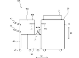
- FIG. 6 is a front view of the image forming apparatus in a state where a second processing unit is disposed at a separation position.
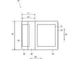
- 1 is a plan view of an image forming apparatus.
- FIG. 4 is a diagram illustrating a rotatable configuration of a paper discharge tray. It is a figure which shows the state by which the 2nd processing unit was arrange
- FIG. 6 is a diagram illustrating a state in which the second processing unit is disposed at a separated position in the image forming apparatus illustrated in FIG. 5.
- (A) is a top view which shows the structure which can be slidably moved while a 2nd processing unit is supported by the upper surface of a 1st processing unit
- (B) is the front view. It is a figure which shows the specific structural example of the paper conveyance path
- an image forming apparatus 10 includes an apparatus main body 20, a first processing unit 30, and a second processing unit 40.
- the image forming apparatus 10 is not particularly limited as long as it performs an image forming process on a sheet.
- Examples of the image forming apparatus 10 include a copying machine, a printer, or a printing apparatus such as an electrophotographic system or an inkjet system.
- the apparatus body 20 includes an automatic document feeder (ADF: Auto Document Feeder) 21, an image forming unit 22, an image reading unit and a paper feed cassette (not shown).
- ADF Auto Document Feeder
- the ADF 21 conveys the original one by one so as to pass through a predetermined image reading position.
- the image reading unit reads an image of a document conveyed at the image reading position and generates image data.
- the paper feed cassette stores paper and supplies the paper to the image forming unit 22 one by one.
- the image forming unit 22 executes an image forming process for forming an image on a sheet based on the image data.
- the first processing unit 30 and the second processing unit 40 are arranged on the same side surface of the apparatus main body 20 so as to overlap each other in the vertical direction 91. For this reason, compared with the case where it arrange
- the first processing unit 30 is fixedly connected to the apparatus main body 20 by screws or the like (not shown).
- the first processing unit 30 is a paper feeding device that accommodates a large volume of paper to be supplied to the image forming unit 22.
- the paper conveyance path of the first processing unit 30 and the reception paper conveyance path in the image forming unit 22 are formed to be continuous with each other.
- the first processing unit 30 supplies sheets one by one to the image forming unit 22 as necessary.
- the second processing unit 40 is disposed on the first processing unit 30.
- the second processing unit 40 is separated from the apparatus main body 20 between a proximity position close to the apparatus main body 20 as shown in FIG. 1 and a predetermined separation position separated from the apparatus main body 20 as shown in FIG. It is configured to be slidable in the direction 92.
- the second processing unit 40 is disposed at a close position when the apparatus main body 20 is in an operating state.
- the second processing unit 40 is a post-processing device that performs post-processing on a sheet on which image forming processing has been performed in the image forming unit 22.
- the receiving paper transport path 41 of the second processing unit 40 is continuous with the discharge paper transport path 221 of the image forming unit 22, and the paper on which image formation processing has been performed smoothly passes to the second processing unit 40.
- post-processing includes stapling, punching, Z-folding, face-up discharging, face-down discharging, and sorting.
- the sheet is fed by the first processing unit 30 and then passed through the sheet conveyance path 220 as shown in FIG. Then, an image is formed by the developing unit 62 and the photosensitive member 63 and the image is fixed by the fixing device 64. Thereafter, the sheet is conveyed to the second processing unit 40 through the sheet conveying path 221, punched by the punch unit 65, and then discharged to the discharge tray 43.
- the second processing unit 40 is arranged at a separated position, so that the connection portion between the second processing unit 40 and the apparatus main body 20 can be opened, and workability with respect to this connection portion is improved. To do. For this reason, even when a problem such as a conveyance failure occurs between the second processing unit 40 and the apparatus main body 20, maintenance such as removal of a sheet can be easily performed.
- the first processing unit 30 has an opening 31 on its upper surface that is large enough to allow a member related to image formation processing to pass therethrough.
- paper is supplied into the first processing unit 30 through the opening 31.
- the opening 31 is exposed to the outside.
- the 1st processing unit 30 is provided with the lid member 32 which can open and close the opening part 31, and the lid member 32 is exposed outside because the 2nd processing unit 40 is arranged in a separation position, Further, the opening 31 is opened by opening the lid member 32.
- the second processing unit 40 by disposing the second processing unit 40 in the separated position, a part of the upper surface of the first processing unit 30 is exposed, and the workability from the upper side with respect to the first processing unit 30 is improved. More specifically, the workability with respect to the inside of the first processing unit 30 through the opening 31 is improved by disposing the second processing unit 40 in the separated position, opening the lid member 32 and opening the opening 31. be able to. For this reason, the maintenance with respect to the 1st processing unit 30 can also be performed easily.
- the second processing unit 40 is configured to be slidable in the separation / contact direction 92 while being supported on the upper surface of the first processing unit 30.
- rail members 60 ⁇ / b> A and 60 ⁇ / b> B extending in the contact / separation direction 92 are laid on the upper surface of the first processing unit 30, and the bottom surface of the second processing unit 40.
- the second processing unit 40 travels on the rail members 60A and 60B. Since the second processing unit 40 slides while being supported on the upper surface of the first processing unit 30, the second processing unit 40 in the separation direction 92 and the depth direction 93 orthogonal to the separation direction 92 and the vertical direction 91. It is possible to prevent an unintentional inclination of the movement path.
- the dimension value of the second processing unit 40 is preferably equal to or less than the dimension value of the first processing unit 30 in each of the separation direction 92 and the depth direction 93.
- the dimension value L2 of the second processing unit 40 is smaller than the dimension value L1 of the first processing unit 30 in the separation direction 92, and the second processing unit 40 and the first processing unit 30 in the depth direction 93. Is the same dimension value D1. Since the second processing unit 40 is not larger than the first processing unit 30 in plan view, the second processing unit 40 is stably supported by the first processing unit 30.
- the second processing unit 40 is slidable in the separating / connecting direction 92, but is arranged so as not to protrude outward from the first processing unit 30 in plan view when the apparatus main body 20 is in an operating state. For this reason, the installation area of the image forming apparatus 10 when the apparatus main body 20 is in the operating state can be further reduced.
- the second processing unit 40 is preferably lighter than the first processing unit 30. Since the position of the center of gravity when the first processing unit 30 and the second processing unit 40 are viewed as one object is lowered, the second processing unit 40 is stably supported by the first processing unit 30.
- the second processing unit 40 includes a second processing unit main body 42 and a paper discharge tray 43.
- the paper discharge tray 43 is supported on the side surface of the second processing unit main body 42 opposite to the apparatus main body 20 so as to be rotatable within a predetermined range around a shaft member 44 extending in the depth direction 93.
- the lower limit position of the rotation range of the paper discharge tray 43 is a position where the paper discharge tray 43 is inclined upward toward the downstream side in the direction away from the apparatus main body 20, that is, the paper transport direction on the paper discharge tray 43.
- the paper discharge tray 43 is configured to be rotatable upward from the lower limit position.
- the upper limit position of the discharge tray 43 is a position where the downstream end of the discharge tray 43 overlaps the downstream end of the second processing tray main body 42 in a plan view in the direction away from the apparatus main body 20. is there.
- the shaft member 44 upstream of the downstream end portion of the second processing tray main body 42
- the downstream end portion of the paper discharge tray 43 is farther from the apparatus main body 20 than the shaft member 44 at the upper limit position. It is arrange
- the paper discharge tray 43 rotates from the upper limit position to the lower limit position due to its own mass. For this reason, since the operation
- the second processing unit 40 is not limited to be configured to be slidable in the separation / contact direction 92 while being supported on the upper surface of the first processing unit 30.
- the rail member on which the second processing unit 40 travels can also be provided with a space from the upper surface of the first processing unit 40 so as to protrude in the horizontal direction from the side surface of the apparatus main body 20.
- the lid member 32 is not necessarily limited to being provided. Without opening the lid member 32, the opening 31 can be opened and closed by sliding the second processing unit 40. In this configuration, it can be considered that the bottom surface of the second processing unit 40 functions as a lid member.
- the dimension value of the portion of the second processing unit 40 excluding the paper discharge tray 43, that is, the second processing unit body 42 is equal to or smaller than the dimension value of the first processing unit 30. It can also be configured. As described above, it is more preferable that the second processing unit 40 is not larger than the first processing unit 30 in a plan view, but the paper discharge tray 43 is considerably lighter than the first processing unit 30 and the second processing unit main body 42. Therefore, the second processing unit 40 is stably supported by the first processing unit 30 by configuring the second processing unit main body 42 so as not to be larger than the first processing unit 30 in plan view.
- the dimension value of the second processing unit 40 may be larger than the dimension value of the first processing unit 30 in at least one of the separation direction 92 and the depth direction 93. it can.
- the same reference numerals are used for members similar to those in the above-described embodiment.
- the second processing unit 40A of the image forming apparatus 10A is configured to be larger than the first processing unit 30 in the separation / contact direction 92.
- the second processing unit 40A includes a second processing unit main body 42A, paper discharge trays 43 and 45, and a support member 46.
- the second processing unit main body 42A is disposed on the first processing unit 30 and is configured to be movable in the contact / separation direction 92 on the upper surface of the first processing unit 30.
- the paper discharge trays 43 and 45 are supported on the side surface of the second processing unit main body 42A opposite to the apparatus main body 20.
- the paper discharge tray 45 can be configured similarly to the paper discharge tray 43.
- the support member 46 extends in the vertical direction 91 between the second processing unit main body 42A and the floor surface at the downstream end in the direction away from the apparatus main body 20, and supports the second processing unit main body 42A.
- the support member 46 has a caster 47 at the bottom.
- the support member 46 is disposed along the side surface of the first processing unit 30 at the close position.
- the second processing unit 40A When the second processing unit 40A is disposed at the separation position, the second processing unit main body 42A is supported by the first processing unit 30 at one end and the support member 46 at the other end in the separation / contact direction 92. Supported by
- the image forming apparatus 10A even when the second processing unit 40A disposed on the upper side is large or heavy, it can be moved stably.
- both the first processing unit 30 and the second processing units 40 and 40A are paper feeders or both post-processing devices, the installation area can be reduced, and the first processing unit 30 and the second processing unit 40 can be reduced. , 40A can be easily maintained. The same effect can be obtained even when the first processing unit 30 is a post-processing device and the second processing units 40 and 40A are paper feeding devices.
Landscapes
- Engineering & Computer Science (AREA)
- Multimedia (AREA)
- Signal Processing (AREA)
- Mechanical Engineering (AREA)
- Physics & Mathematics (AREA)
- General Physics & Mathematics (AREA)
- Health & Medical Sciences (AREA)
- Biomedical Technology (AREA)
- General Health & Medical Sciences (AREA)
- Electrophotography Configuration And Component (AREA)
- Paper Feeding For Electrophotography (AREA)
- Collation Of Sheets And Webs (AREA)
- Control Or Security For Electrophotography (AREA)
- Accessory Devices And Overall Control Thereof (AREA)
- Pile Receivers (AREA)
Abstract
画像形成装置(10)は、装置本体(20)、第1処理ユニット(30)及び第2処理ユニット(40)を備える。装置本体(20)は、用紙に画像形成処理を行う。第1処理ユニット(30)及び第2処理ユニット(40)は、装置本体20の同一の側面側に互いに上下方向(91)に重ねて配置される。第2処理ユニット(40)は、第1処理ユニット(30)の上に配置され、装置本体(20)に対する離接方向(92)にスライド移動自在に構成される。
Description
この発明は、用紙に画像形成処理を行う装置本体の側面側に配置される第1処理ユニット及び第2処理ユニットを有する処理装置、並びにこれを備える画像形成装置に関する。
従来より、画像形成装置の中には、用紙に画像形成処理を行う装置本体の他に、機能を拡張するための複数の処理ユニットを有する処理装置を備えるものがある。例えば、処理ユニットとして、装置本体へ供給するための大容量の用紙を収容する給紙装置、装置本体において画像形成処理が施された用紙に後処理を施す後処理装置が挙げられる。しかし、第1処理ユニットと第2処理ユニットとを装置本体の互いに反対側の側面に備えたのでは、画像形成装置の設置面積が増大してしまう。
そこで、給紙トレイの上に排紙トレイを備えた画像形成装置が知られている(例えば、特許文献1参照。)。この従来の画像形成装置では、給紙トレイと排紙トレイとを上下に重ねて備えることで、給紙トレイと排紙トレイとが装置本体の互いに異なる側面に備えられた場合と比較して設置面積の減少が図られている。
しかし、従来の画像形成装置では、給紙トレイ及び排紙トレイは装置本体に対する離接方向にスライド移動することができないので、給紙又は排紙された用紙が装置本体との接続部で搬送不良を起こした場合は、用紙の取り除き等のメンテナンスを行うことが困難である。
また、従来の画像形成装置では、装置本体の同一側面に上下に重ねて配置される物が、給紙トレイ及び排紙トレイといった軽量かつ簡易な構造の部材であって処理ユニットではない。従来の画像形成装置では、給紙トレイ及び排紙トレイが回動自在に構成されているが、給紙トレイ及び排紙トレイが軽量だからこそ可能な構成であり、比較的質量の大きい処理ユニットに同様の構成を適用することは困難である。このため、従来の画像形成装置の構成では、処理ユニットのメンテナンスを行うことが困難である。
この発明の目的は、設置面積を減少できるとともに、装置本体の側面に備えられた処理ユニットのメンテナンスを容易に行うことができる処理装置、およびこれを備えた画像形成装置を提供することにある。
この発明の処理装置は、第1処理ユニット及び第2処理ユニットを備える。第1処理ユニット及び第2処理ユニットは、用紙に画像形成処理を行う装置本体の同一の側面側に互いに上下方向に重ねて配置される。第2処理ユニットは、第1処理ユニットの上に配置され、装置本体に対する離接方向にスライド移動自在に構成される。この発明の画像形成装置は、装置本体、及び処理装置を備える。
この構成では、第1処理ユニットと第2処理ユニットとが装置本体の同一の側面側に互いに上下方向に重ねて配置されるので、装置本体の互いに異なる側面に配置された場合と比較して設置面積を減少させることができる。また、第2処理ユニットが装置本体に対する離接方向にスライド移動自在なので、第2処理ユニットと装置本体との接続部を開放することができ、この接続部に対する作業性が向上する。このため、第2処理ユニットと装置本体との間で搬送不良が起こった場合でも用紙の取り除き等のメンテナンスを容易に行うことができる。さらに、上側の第2処理ユニットをスライド移動させて第1処理ユニットの上面の一部を露出させることで、第1処理ユニットに対する上方からの作業性が向上する。このため、第1処理ユニットに対するメンテナンスをも容易に行うことができる。
この発明によれば、設置面積を減少できるとともに、装置本体の側面に備えられた第1処理ユニット及び第2処理ユニットのメンテナンスを容易化することができる。
図1に示すように、この発明の実施形態に係る画像形成装置10は、装置本体20、第1処理ユニット30、及び第2処理ユニット40を備えている。画像形成装置10は、用紙に画像形成処理を行うものであれば特に限定されない。画像形成装置10として、例えば、電子写真方式やインクジェット方式などの、複写機やプリンタ、又は印刷装置などが挙げられる。
装置本体20は、自動原稿搬送装置(ADF:Auto Document Feeder)21、画像形成部22、並びに図示しない画像読取部及び給紙カセットを有する。ADF21は、原稿を1枚ずつ所定の画像読取位置を経由するように搬送する。画像読取部は、画像読取位置を搬送される原稿の画像を読み取って画像データを生成する。
給紙カセットは、用紙を収容しており、画像形成部22へ用紙を1枚ずつ供給する。画像形成部22は、画像データに基づいて用紙に画像を形成する画像形成処理を実行する。
第1処理ユニット30と第2処理ユニット40とは、装置本体20の同一の側面側に、互いに上下方向91に重ねて配置されている。このため、装置本体20の互いに異なる側面に配置された場合と比較して、設置面積を減少させることができる。
第1処理ユニット30は、図示しないビス等によって、装置本体20に固定的に連結されている。一例として、第1処理ユニット30は、画像形成部22へ供給するための大容量の用紙を収容する給紙装置である。第1処理ユニット30の用紙搬送路と画像形成部22における受入用の用紙搬送路とは、互いに連続するように形成されている。第1処理ユニット30は、必要に応じて画像形成部22へ用紙を1枚ずつ供給する。装置本体20とは別に給紙装置を備えることで、大量の用紙を給紙装置に収容することができ、1回の補給で大量の用紙に連続して画像形成処理を行うことができる。
第2処理ユニット40は、第1処理ユニット30の上に配置されている。第2処理ユニット40は、図1に示すように装置本体20に近接する近接位置と、図2に示すように装置本体20から離間した所定の離間位置との間で、装置本体20に対する離接方向92にスライド移動自在に構成されている。第2処理ユニット40は、装置本体20が動作状態にあるとき、近接位置に配置される。
一例として、第2処理ユニット40は、画像形成部22において画像形成処理が施された用紙に後処理を施す後処理装置である。近接位置において、第2処理ユニット40の受入用の用紙搬送路41は、画像形成部22の排出用の用紙搬送路221に連続し、画像形成処理済みの用紙が円滑に第2処理ユニット40へ搬送される。例えば、後処理として、ステープル処理、パンチ処理、Z折り処理、フェースアップ排出処理、フェースダウン排出処理、ソート処理が挙げられる。画像形成処理が施された用紙に後処理を施すことで、事務処理効率が向上する。用紙の搬送経路は特に限定されないが、一例として、電子写真方式の複写機の場合、図8に示すように、用紙は、第1処理ユニット30によって給紙された後、用紙搬送路220を通って搬送され、現像部62や感光体63等によって画像形成され、定着装置64によって画像を定着される。その後、用紙は用紙搬送路221を通じて第2処理ユニット40へ搬送され、パンチ部65によってパンチ処理された後、排紙トレイ43へ排紙される。
図2に示すように、第2処理ユニット40が離間位置に配置されることで、第2処理ユニット40と装置本体20との接続部を開放することができ、この接続部に対する作業性が向上する。このため、第2処理ユニット40と装置本体20との間で搬送不良等の問題が起こった場合でも用紙の取り除き等のメンテナンスを容易に行うことができる。
第1処理ユニット30は、画像形成処理に関する部材が通過自在な大きさの開口部31を上面に有する。この実施形態では、開口部31を通して第1処理ユニット30内に用紙が補給される。第2処理ユニット40が離間位置に配置された状態において、開口部31は外部に露出する。この実施形態では、第1処理ユニット30は、開口部31を開閉自在な蓋部材32を備えており、第2処理ユニット40が離間位置に配置されることで蓋部材32が外部に露出し、さらに蓋部材32を開くことで開口部31が開放される。
このように、第2処理ユニット40を離間位置に配置することで第1処理ユニット30の上面の一部が露出し、第1処理ユニット30に対する上方からの作業性が向上する。より具体的には、第2処理ユニット40を離間位置に配置し、蓋部材32を開いて開口部31を開放することで、開口部31を通して第1処理ユニット30の内部に対する作業性を向上することができる。このため、第1処理ユニット30に対するメンテナンスをも容易に行うことができる。
第2処理ユニット40は、第1処理ユニット30の上面に支持されつつ離接方向92にスライド移動自在に構成されることが好ましい。一例として、図7(A)及び図7(B)に示すように、第1処理ユニット30の上面に、離接方向92に延びるレール部材60A,60Bが敷設され、第2処理ユニット40の底面にコロ61が設けられ、第2処理ユニット40はレール部材60A,60B上を走行する。第2処理ユニット40が第1処理ユニット30の上面に支持されつつスライド移動するので、離接方向92や、離接方向92及び上下方向91に直交する奥行き方向93への、第2処理ユニット40の移動経路の意図しない傾斜を防止することができる。
図3に示すように、離接方向92及び奥行き方向93のそれぞれにおいて、第2処理ユニット40の寸法値は、第1処理ユニット30の寸法値以下であることが好ましい。この実施形態では、離接方向92において、第2処理ユニット40の寸法値L2は第1処理ユニット30の寸法値L1よりも小さく、奥行き方向93において、第2処理ユニット40と第1処理ユニット30とは同じ寸法値D1である。平面視において第2処理ユニット40が第1処理ユニット30よりも大きくないので、第2処理ユニット40が第1処理ユニット30によって安定的に支持される。
第2処理ユニット40は、離接方向92にスライド移動自在であるが、装置本体20が動作状態にあるとき、平面視において第1処理ユニット30の外方へ突出しないように配置される。このため、装置本体20が動作状態にあるときの画像形成装置10の設置面積をより減少させることができる。
第2処理ユニット40は、第1処理ユニット30よりも軽いことが好ましい。第1処理ユニット30と第2処理ユニット40とを1個の物体と見たときの重心位置が低くなるので、第2処理ユニット40が第1処理ユニット30によって安定的に支持される。
図4に示すように、この実施形態では、第2処理ユニット40は、第2処理ユニット本体42、及び排紙トレイ43を有する。排紙トレイ43は、奥行き方向93に延びる軸部材44を中心に所定範囲内で回転自在に、第2処理ユニット本体42の装置本体20とは反対側の側面に支持されている。
排紙トレイ43の回転範囲のうち下限位置は、装置本体20から離間する方向即ち排紙トレイ43上における用紙搬送方向において、排紙トレイ43が下流側へ向けて上り傾斜する位置であることが好ましい。排紙トレイ43は、下限位置から上方へ回転自在に構成されている。これによって、第2処理ユニット40を装置本体20から離間する方向へ移動させた際に排紙トレイ43が壁等の外部物体50に衝突した場合でも、排紙トレイ43が上方へ回転することで、排紙トレイ43の破損を防止することができる。また、第2処理ユニット40を装置本体20から離間する方向へ移動させた際に、排紙トレイ43が外部物体50に衝突しない場合でも、排紙トレイ43を上方へ回転させることで、設置面積をより減少させることができる。
また、一例として、排紙トレイ43の上限位置は、装置本体20から離間する方向において排紙トレイ43の下流側端部が第2処理トレイ本体42の下流側端部と平面視において重なる位置である。軸部材44が第2処理トレイ本体42の下流側端部よりも上流側に配置されることで、上限位置において、排紙トレイ43の下流側端部が軸部材44よりも装置本体20から離間する方向の下流側に配置される。これによって、第2処理ユニット40を離間位置から近接位置へ向けて移動させた際に、排紙トレイ43は自身の質量によって上限位置から下限位置へ回転する。このため、排紙トレイ43を回転させる作業を必要としないので、作業性が向上する。
なお、第2処理ユニット40は、第1処理ユニット30の上面に支持されつつ離接方向92にスライド移動自在に構成されることに限定されない。第2処理ユニット40が走行するレール部材は、装置本体20の側面から水平方向へ突出するように、第1処理ユニット40の上面から空間をあけて設けることもできる。
また、蓋部材32は必ずしも備えられることに限定されない。蓋部材32を備えることなく、第2処理ユニット40をスライド移動させることで、開口部31を開閉するように構成することもできる。この構成では、第2処理ユニット40の底面が蓋部材として機能すると考えることもできる。
さらに、離接方向92及び奥行き方向93のそれぞれにおいて、第2処理ユニット40のうち排紙トレイ43を除く部分即ち第2処理ユニット本体42の寸法値が、第1処理ユニット30の寸法値以下であるように構成することもできる。上述のように平面視において第2処理ユニット40が第1処理ユニット30よりも大きくない方がより好ましいが、第1処理ユニット30及び第2処理ユニット本体42と比較すると排紙トレイ43はかなり軽量なので、平面視において第2処理ユニット本体42が第1処理ユニット30よりも大きくならないように構成することで、第2処理ユニット40が第1処理ユニット30によって安定的に支持される。
図5及び図6に示すように、離接方向92及び奥行き方向93のうち少なくともいずれか一方において、第2処理ユニット40の寸法値を、第1処理ユニット30の寸法値よりも大きくすることもできる。なお、説明の便宜上、上述の実施形態と同様の部材については同じ符号を用いる。
この実施形態に係る画像形成装置10Aの第2処理ユニット40Aは、離接方向92において第1処理ユニット30よりも大きく構成されている。第2処理ユニット40Aは、第2処理ユニット本体42A、排紙トレイ43,45、及び支持部材46を有する。
第2処理ユニット本体42Aは、第1処理ユニット30の上に配置されて、第1処理ユニット30の上面を離接方向92に移動自在に構成されている。
排紙トレイ43,45は、第2処理ユニット本体42Aの装置本体20とは反対側の側面に支持されている。排紙トレイ45は、排紙トレイ43と同様に構成することができる。
支持部材46は、装置本体20から離間する方向における下流側端部において、第2処理ユニット本体42Aと床面との間で上下方向91に延び、第2処理ユニット本体42Aを支持している。支持部材46は、底部にキャスタ47を有している。支持部材46は、近接位置において、第1処理ユニット30の側面に沿うように配置される。
第2処理ユニット40Aが離間位置に配置された際、第2処理ユニット本体42Aは、離接方向92において、一方の端部を第1処理ユニット30に支持され、他方の端部を支持部材46に支持される。
画像形成装置10Aによれば、上側に配置される第2処理ユニット40Aが大型又は重い場合でも、安定的に移動させることができる。
なお、第1処理ユニット30と第2処理ユニット40,40Aとが、ともに給紙装置又はともに後処理装置であっても、設置面積を減少できるとともに、第1処理ユニット30及び第2処理ユニット40,40Aのメンテナンスを容易化することができるという効果を奏することができる。また、第1処理ユニット30が後処理装置であり、第2処理ユニット40,40Aが給紙装置である場合でも同様の効果を奏することができる。
上述の実施形態の説明は、すべての点で例示であって、制限的なものではないと考えられるべきである。本発明の範囲は、上述の実施形態ではなく、特許請求の範囲によって示される。さらに、本発明の範囲には、特許請求の範囲と均等の意味および範囲内でのすべての変更が含まれることが意図される。
10,10A 画像形成装置
20 装置本体
30 第1処理ユニット
31 開口部
40,40A 第2処理ユニット
42,42A 第2処理ユニット本体
43,45 排紙トレイ
91 上下方向
92 離接方向
93 奥行き方向
20 装置本体
30 第1処理ユニット
31 開口部
40,40A 第2処理ユニット
42,42A 第2処理ユニット本体
43,45 排紙トレイ
91 上下方向
92 離接方向
93 奥行き方向
Claims (18)
- 用紙に画像形成処理を行う装置本体の同一の側面側に互いに上下方向に重ねて配置された第1処理ユニット及び第2処理ユニットを備え、
前記第2処理ユニットは、前記第1処理ユニットの上に配置され、前記装置本体に対する離接方向にスライド移動自在に構成される、処理装置。 - 前記第2処理ユニットは、前記第1処理ユニットの上面に支持されつつ前記離接方向にスライド移動自在に構成される、請求項1に記載の処理装置。
- 前記離接方向並びに前記離接方向及び前記上下方向に直交する奥行き方向のそれぞれにおいて、前記第2処理ユニットの寸法値は前記第1処理ユニットの寸法値以下である、請求項1に記載の処理装置。
- 前記装置本体が動作状態にあるとき、平面視において前記第2処理ユニットは前記第1処理ユニットの外方へ突出しない、請求項3に記載の処理装置。
- 前記第1処理ユニットは、画像形成処理に関する部材が通過自在な開口部を上面に有し、
前記第2処理ユニットが前記装置本体から離間した所定の離間位置に配置された状態において、前記開口部が露出する、請求項1に記載の処理装置。 - 前記第2処理ユニットは、前記第1処理ユニットよりも軽い、請求項1に記載の処理装置。
- 前記第2処理ユニットは、第2処理ユニット本体、並びに、前記第2処理ユニット本体の前記装置本体とは反対側の側面に配置された排紙トレイであって前記離接方向及び前記上下方向に直交する奥行き方向に延びる軸部材を中心に所定範囲内で回転自在に前記第2処理ユニット本体に支持された排紙トレイを有する、請求項1に記載の処理装置。
- 前記第1処理ユニットは、前記装置本体へ供給する用紙を収容する給紙装置である、請求項1に記載の処理装置。
- 前記第2処理ユニットは、前記装置本体において画像形成処理が施された用紙に後処理を施す後処理装置である、請求項1に記載の処理装置。
- 用紙に画像形成処理を行う装置本体と、
前記装置本体の同一の側面側に互いに上下方向に重ねて配置された第1処理ユニット及び第2処理ユニットと、を備え、
前記第2処理ユニットは、前記第1処理ユニットの上に配置され、前記装置本体に対する離接方向にスライド移動自在に構成される、画像形成装置。 - 前記第2処理ユニットは、前記第1処理ユニットの上面に支持されつつ前記離接方向にスライド移動自在に構成される、請求項10に記載の画像形成装置。
- 前記離接方向並びに前記離接方向及び前記上下方向に直交する奥行き方向のそれぞれにおいて、前記第2処理ユニットの寸法値は前記第1処理ユニットの寸法値以下である、請求項10に記載の画像形成装置。
- 前記装置本体が動作状態にあるとき、平面視において前記第2処理ユニットは前記第1処理ユニットの外方へ突出しない、請求項12に記載の画像形成装置。
- 前記第1処理ユニットは、画像形成処理に関する部材が通過自在な開口部を上面に有し、
前記第2処理ユニットが前記装置本体から離間した所定の離間位置に配置された状態において、前記開口部が露出する、請求項10に記載の画像形成装置。 - 前記第2処理ユニットは、前記第1処理ユニットよりも軽い、請求項10に記載の画像形成装置。
- 前記第2処理ユニットは、第2処理ユニット本体、並びに、前記第2処理ユニット本体の前記装置本体とは反対側の側面に配置された排紙トレイであって前記離接方向及び前記上下方向に直交する奥行き方向に延びる軸部材を中心に所定範囲内で回転自在に前記第2処理ユニット本体に支持された排紙トレイを有する、請求項10に記載の画像形成装置。
- 前記第1処理ユニットは、前記装置本体へ供給する用紙を収容する給紙装置である、請求項10に記載の画像形成装置。
- 前記第2処理ユニットは、前記装置本体において画像形成処理が施された用紙に後処理を施す後処理装置である、請求項10に記載の画像形成装置。
Priority Applications (4)
| Application Number | Priority Date | Filing Date | Title |
|---|---|---|---|
| CN201380033501.3A CN104412172B (zh) | 2012-06-25 | 2013-06-24 | 处理装置和图像形成装置 |
| US14/405,954 US20150123339A1 (en) | 2012-06-25 | 2013-06-24 | Processing device and image forming apparatus |
| US15/089,539 US9630798B2 (en) | 2012-06-25 | 2016-04-02 | Image forming apparatus |
| US15/461,615 US10196226B2 (en) | 2012-06-25 | 2017-03-17 | Image forming apparatus |
Applications Claiming Priority (2)
| Application Number | Priority Date | Filing Date | Title |
|---|---|---|---|
| JP2012-141577 | 2012-06-25 | ||
| JP2012141577A JP5865787B2 (ja) | 2012-06-25 | 2012-06-25 | 画像形成装置 |
Related Child Applications (2)
| Application Number | Title | Priority Date | Filing Date |
|---|---|---|---|
| US14/405,954 A-371-Of-International US20150123339A1 (en) | 2012-06-25 | 2013-06-24 | Processing device and image forming apparatus |
| US15/089,539 Continuation US9630798B2 (en) | 2012-06-25 | 2016-04-02 | Image forming apparatus |
Publications (1)
| Publication Number | Publication Date |
|---|---|
| WO2014002942A1 true WO2014002942A1 (ja) | 2014-01-03 |
Family
ID=49783088
Family Applications (1)
| Application Number | Title | Priority Date | Filing Date |
|---|---|---|---|
| PCT/JP2013/067236 Ceased WO2014002942A1 (ja) | 2012-06-25 | 2013-06-24 | 処理装置および画像形成装置 |
Country Status (4)
| Country | Link |
|---|---|
| US (3) | US20150123339A1 (ja) |
| JP (1) | JP5865787B2 (ja) |
| CN (2) | CN110077875A (ja) |
| WO (1) | WO2014002942A1 (ja) |
Families Citing this family (3)
| Publication number | Priority date | Publication date | Assignee | Title |
|---|---|---|---|---|
| JP5512874B1 (ja) | 2012-12-04 | 2014-06-04 | シャープ株式会社 | 処理装置及び画像形成装置 |
| JP6508453B2 (ja) * | 2014-12-12 | 2019-05-08 | セイコーエプソン株式会社 | シート製造装置 |
| JP7400223B2 (ja) | 2019-06-18 | 2023-12-19 | セイコーエプソン株式会社 | 記録装置 |
Citations (6)
| Publication number | Priority date | Publication date | Assignee | Title |
|---|---|---|---|---|
| JP2002308520A (ja) * | 2001-04-11 | 2002-10-23 | Canon Inc | 画像形成装置 |
| JP2004037942A (ja) * | 2002-07-04 | 2004-02-05 | Canon Inc | 画像形成装置 |
| JP2005082325A (ja) * | 2003-09-09 | 2005-03-31 | Kyocera Mita Corp | 後処理装置 |
| JP2008139548A (ja) * | 2006-12-01 | 2008-06-19 | Canon Inc | 画像形成装置 |
| JP2008275694A (ja) * | 2007-04-25 | 2008-11-13 | Kyocera Mita Corp | 転倒防止装置、及び画像形成装置 |
| JP2009001362A (ja) * | 2007-06-20 | 2009-01-08 | Sharp Corp | 画像形成装置 |
Family Cites Families (26)
| Publication number | Priority date | Publication date | Assignee | Title |
|---|---|---|---|---|
| DE3219784A1 (de) * | 1981-05-26 | 1982-12-16 | Konishiroku Photo Industry Co., Ltd., Tokyo | Kassettenwechselvorrichtung und damit ausgeruestetes vervielfaeltigungsgeraet |
| US6112047A (en) * | 1996-03-11 | 2000-08-29 | Ricoh Company, Ltd. | Image forming apparatus having a substantially vertical sheet transport path and a relaying mechanism that cooperate to transfer a sheet to a sheet discharge section |
| JPH10218476A (ja) | 1997-01-31 | 1998-08-18 | Canon Aptecs Kk | シート処理装置及びこれを備える画像形成装置 |
| JPH11130315A (ja) * | 1997-10-27 | 1999-05-18 | Canon Inc | 画像形成システム |
| JP2001125332A (ja) | 1999-06-24 | 2001-05-11 | Ricoh Co Ltd | 画像形成装置 |
| JP3548494B2 (ja) * | 2000-04-18 | 2004-07-28 | キヤノン株式会社 | 画像形成装置 |
| US6647243B2 (en) * | 2000-10-16 | 2003-11-11 | Canon Kabushiki Kaisha | Sheet treating apparatus, method of mounting sheet treating apparatus, and image forming apparatus |
| JP3748382B2 (ja) * | 2001-03-05 | 2006-02-22 | シャープ株式会社 | 画像形成装置の排紙処理装置 |
| JP2002333750A (ja) * | 2001-05-09 | 2002-11-22 | Canon Inc | 画像形成装置 |
| US7450881B2 (en) * | 2002-04-18 | 2008-11-11 | Krdc Co., Ltd. | Finishing apparatus of image forming apparatus |
| US6876830B2 (en) | 2002-09-05 | 2005-04-05 | Sharp Kabushiki Kaisha | Image forming system having a space for unjamming |
| JP2004101605A (ja) | 2002-09-05 | 2004-04-02 | Sharp Corp | 画像形成システム |
| JP4536358B2 (ja) | 2002-12-04 | 2010-09-01 | 株式会社リコー | 画像形成装置 |
| JP4769420B2 (ja) * | 2003-04-09 | 2011-09-07 | 株式会社リコー | 画像形成装置 |
| JP4015582B2 (ja) | 2003-05-09 | 2007-11-28 | ニスカ株式会社 | 画像形成装置 |
| JP2006069763A (ja) * | 2004-09-03 | 2006-03-16 | Fuji Xerox Co Ltd | シート折畳装置 |
| JP2006143403A (ja) | 2004-11-19 | 2006-06-08 | Sharp Corp | シート反転搬送装置およびそれを備えてなる画像形成装置、シート反転搬送方法 |
| US20080023909A1 (en) * | 2006-07-28 | 2008-01-31 | Hewlett-Packard Company | Media tray |
| JP2008096898A (ja) | 2006-10-16 | 2008-04-24 | Fuji Xerox Co Ltd | 画像形成装置 |
| JP3979444B2 (ja) | 2006-10-17 | 2007-09-19 | 富士ゼロックス株式会社 | 画像形成装置 |
| JP5433177B2 (ja) * | 2008-07-04 | 2014-03-05 | 京セラドキュメントソリューションズ株式会社 | 用紙排出装置および画像形成装置 |
| US20100194036A1 (en) * | 2009-02-05 | 2010-08-05 | Kabushiki Kaisha Toshiba | Image forming apparatus |
| JP2011084346A (ja) * | 2009-10-13 | 2011-04-28 | Konica Minolta Business Technologies Inc | 用紙搬送装置、画像形成装置、用紙搬送装置の制御方法、及び用紙搬送装置の制御プログラム |
| JP5526083B2 (ja) * | 2011-07-05 | 2014-06-18 | 京セラドキュメントソリューションズ株式会社 | 画像形成装置 |
| JP6147011B2 (ja) * | 2013-01-31 | 2017-06-14 | キヤノン株式会社 | 連結機構、後処理装置及び画像形成装置 |
| KR20150019645A (ko) * | 2013-08-14 | 2015-02-25 | 삼성전자주식회사 | 화상형성장치 |
-
2012
- 2012-06-25 JP JP2012141577A patent/JP5865787B2/ja active Active
-
2013
- 2013-06-24 US US14/405,954 patent/US20150123339A1/en not_active Abandoned
- 2013-06-24 CN CN201910298073.6A patent/CN110077875A/zh active Pending
- 2013-06-24 WO PCT/JP2013/067236 patent/WO2014002942A1/ja not_active Ceased
- 2013-06-24 CN CN201380033501.3A patent/CN104412172B/zh not_active Expired - Fee Related
-
2016
- 2016-04-02 US US15/089,539 patent/US9630798B2/en not_active Expired - Fee Related
-
2017
- 2017-03-17 US US15/461,615 patent/US10196226B2/en active Active
Patent Citations (6)
| Publication number | Priority date | Publication date | Assignee | Title |
|---|---|---|---|---|
| JP2002308520A (ja) * | 2001-04-11 | 2002-10-23 | Canon Inc | 画像形成装置 |
| JP2004037942A (ja) * | 2002-07-04 | 2004-02-05 | Canon Inc | 画像形成装置 |
| JP2005082325A (ja) * | 2003-09-09 | 2005-03-31 | Kyocera Mita Corp | 後処理装置 |
| JP2008139548A (ja) * | 2006-12-01 | 2008-06-19 | Canon Inc | 画像形成装置 |
| JP2008275694A (ja) * | 2007-04-25 | 2008-11-13 | Kyocera Mita Corp | 転倒防止装置、及び画像形成装置 |
| JP2009001362A (ja) * | 2007-06-20 | 2009-01-08 | Sharp Corp | 画像形成装置 |
Also Published As
| Publication number | Publication date |
|---|---|
| CN104412172B (zh) | 2019-05-17 |
| US20170183187A1 (en) | 2017-06-29 |
| US20160214824A1 (en) | 2016-07-28 |
| JP2014006365A (ja) | 2014-01-16 |
| US20150123339A1 (en) | 2015-05-07 |
| JP5865787B2 (ja) | 2016-02-17 |
| CN110077875A (zh) | 2019-08-02 |
| US9630798B2 (en) | 2017-04-25 |
| CN104412172A (zh) | 2015-03-11 |
| US10196226B2 (en) | 2019-02-05 |
Similar Documents
| Publication | Publication Date | Title |
|---|---|---|
| US10252873B2 (en) | Processing apparatus and image forming apparatus | |
| WO2014002942A1 (ja) | 処理装置および画像形成装置 | |
| US9878862B2 (en) | Image forming apparatus that enables adjusting pressure between fixed guide and movable guide | |
| JP6639248B2 (ja) | 画像形成装置及びシート処理装置 | |
| CN102923504B (zh) | 片材给送装置和成像装置 | |
| JP6400762B2 (ja) | 画像形成装置 | |
| US20110215516A1 (en) | Image forming apparatus, sheet guide apparatus and sheet guide method | |
| JP2006235002A (ja) | 画像形成装置 | |
| JP2018080043A (ja) | シート積載装置およびこれを備えた画像形成装置 | |
| JP6757514B2 (ja) | シート材給送装置及び画像形成装置 | |
| JP2016085468A (ja) | 画像形成装置 | |
| JP6122803B2 (ja) | シート処理装置及び画像形成装置 | |
| JP4684731B2 (ja) | 画像形成装置 | |
| JP2009175350A (ja) | 付属処理装置及びこれを用いた記録材処理装置 | |
| JP6245800B2 (ja) | 画像形成装置 | |
| JP6245110B2 (ja) | シート搬送装置、およびこれを備えた画像形成装置 | |
| JP2016030689A (ja) | シート給送装置及び画像形成装置 | |
| JP2006178011A (ja) | 画像形成装置 | |
| JP5746401B2 (ja) | 給紙装置および画像形成装置 | |
| JP2010058944A (ja) | シート後処理装置 | |
| JP6222029B2 (ja) | 給紙装置、およびこれを備えた画像形成装置 | |
| JP2004352396A (ja) | シート給送装置 | |
| CN203998223U (zh) | 薄片后处理装置及图像形成装置 | |
| JP2014227248A (ja) | シート搬送装置、及びこれを備えた画像形成装置 | |
| JP2016078956A (ja) | 給紙装置及び画像形成装置 |
Legal Events
| Date | Code | Title | Description |
|---|---|---|---|
| 121 | Ep: the epo has been informed by wipo that ep was designated in this application |
Ref document number: 13809796 Country of ref document: EP Kind code of ref document: A1 |
|
| WWE | Wipo information: entry into national phase |
Ref document number: 14405954 Country of ref document: US |
|
| NENP | Non-entry into the national phase |
Ref country code: DE |
|
| 122 | Ep: pct application non-entry in european phase |
Ref document number: 13809796 Country of ref document: EP Kind code of ref document: A1 |