WO2013190840A1 - トナー - Google Patents
トナー Download PDFInfo
- Publication number
- WO2013190840A1 WO2013190840A1 PCT/JP2013/003837 JP2013003837W WO2013190840A1 WO 2013190840 A1 WO2013190840 A1 WO 2013190840A1 JP 2013003837 W JP2013003837 W JP 2013003837W WO 2013190840 A1 WO2013190840 A1 WO 2013190840A1
- Authority
- WO
- WIPO (PCT)
- Prior art keywords
- resin
- toner
- low
- temperature
- acid
- Prior art date
- Legal status (The legal status is an assumption and is not a legal conclusion. Google has not performed a legal analysis and makes no representation as to the accuracy of the status listed.)
- Ceased
Links
Classifications
-
- G—PHYSICS
- G03—PHOTOGRAPHY; CINEMATOGRAPHY; ANALOGOUS TECHNIQUES USING WAVES OTHER THAN OPTICAL WAVES; ELECTROGRAPHY; HOLOGRAPHY
- G03G—ELECTROGRAPHY; ELECTROPHOTOGRAPHY; MAGNETOGRAPHY
- G03G9/00—Developers
- G03G9/08—Developers with toner particles
- G03G9/087—Binders for toner particles
- G03G9/08742—Binders for toner particles comprising macromolecular compounds obtained otherwise than by reactions only involving carbon-to-carbon unsaturated bonds
- G03G9/08755—Polyesters
-
- C—CHEMISTRY; METALLURGY
- C08—ORGANIC MACROMOLECULAR COMPOUNDS; THEIR PREPARATION OR CHEMICAL WORKING-UP; COMPOSITIONS BASED THEREON
- C08G—MACROMOLECULAR COMPOUNDS OBTAINED OTHERWISE THAN BY REACTIONS ONLY INVOLVING UNSATURATED CARBON-TO-CARBON BONDS
- C08G63/00—Macromolecular compounds obtained by reactions forming a carboxylic ester link in the main chain of the macromolecule
- C08G63/02—Polyesters derived from hydroxycarboxylic acids or from polycarboxylic acids and polyhydroxy compounds
- C08G63/12—Polyesters derived from hydroxycarboxylic acids or from polycarboxylic acids and polyhydroxy compounds derived from polycarboxylic acids and polyhydroxy compounds
- C08G63/16—Dicarboxylic acids and dihydroxy compounds
-
- C—CHEMISTRY; METALLURGY
- C08—ORGANIC MACROMOLECULAR COMPOUNDS; THEIR PREPARATION OR CHEMICAL WORKING-UP; COMPOSITIONS BASED THEREON
- C08G—MACROMOLECULAR COMPOUNDS OBTAINED OTHERWISE THAN BY REACTIONS ONLY INVOLVING UNSATURATED CARBON-TO-CARBON BONDS
- C08G63/00—Macromolecular compounds obtained by reactions forming a carboxylic ester link in the main chain of the macromolecule
- C08G63/02—Polyesters derived from hydroxycarboxylic acids or from polycarboxylic acids and polyhydroxy compounds
- C08G63/12—Polyesters derived from hydroxycarboxylic acids or from polycarboxylic acids and polyhydroxy compounds derived from polycarboxylic acids and polyhydroxy compounds
- C08G63/16—Dicarboxylic acids and dihydroxy compounds
- C08G63/18—Dicarboxylic acids and dihydroxy compounds the acids or hydroxy compounds containing carbocyclic rings
- C08G63/19—Hydroxy compounds containing aromatic rings
-
- C—CHEMISTRY; METALLURGY
- C08—ORGANIC MACROMOLECULAR COMPOUNDS; THEIR PREPARATION OR CHEMICAL WORKING-UP; COMPOSITIONS BASED THEREON
- C08G—MACROMOLECULAR COMPOUNDS OBTAINED OTHERWISE THAN BY REACTIONS ONLY INVOLVING UNSATURATED CARBON-TO-CARBON BONDS
- C08G67/00—Macromolecular compounds obtained by reactions forming in the main chain of the macromolecule a linkage containing oxygen or oxygen and carbon, not provided for in groups C08G2/00 - C08G65/00
- C08G67/02—Copolymers of carbon monoxide and aliphatic unsaturated compounds
-
- C—CHEMISTRY; METALLURGY
- C08—ORGANIC MACROMOLECULAR COMPOUNDS; THEIR PREPARATION OR CHEMICAL WORKING-UP; COMPOSITIONS BASED THEREON
- C08L—COMPOSITIONS OF MACROMOLECULAR COMPOUNDS
- C08L67/00—Compositions of polyesters obtained by reactions forming a carboxylic ester link in the main chain; Compositions of derivatives of such polymers
-
- C—CHEMISTRY; METALLURGY
- C08—ORGANIC MACROMOLECULAR COMPOUNDS; THEIR PREPARATION OR CHEMICAL WORKING-UP; COMPOSITIONS BASED THEREON
- C08L—COMPOSITIONS OF MACROMOLECULAR COMPOUNDS
- C08L67/00—Compositions of polyesters obtained by reactions forming a carboxylic ester link in the main chain; Compositions of derivatives of such polymers
- C08L67/02—Polyesters derived from dicarboxylic acids and dihydroxy compounds
-
- C—CHEMISTRY; METALLURGY
- C08—ORGANIC MACROMOLECULAR COMPOUNDS; THEIR PREPARATION OR CHEMICAL WORKING-UP; COMPOSITIONS BASED THEREON
- C08L—COMPOSITIONS OF MACROMOLECULAR COMPOUNDS
- C08L67/00—Compositions of polyesters obtained by reactions forming a carboxylic ester link in the main chain; Compositions of derivatives of such polymers
- C08L67/02—Polyesters derived from dicarboxylic acids and dihydroxy compounds
- C08L67/03—Polyesters derived from dicarboxylic acids and dihydroxy compounds the dicarboxylic acids and dihydroxy compounds having the carboxyl- and the hydroxy groups directly linked to aromatic rings
-
- G—PHYSICS
- G03—PHOTOGRAPHY; CINEMATOGRAPHY; ANALOGOUS TECHNIQUES USING WAVES OTHER THAN OPTICAL WAVES; ELECTROGRAPHY; HOLOGRAPHY
- G03G—ELECTROGRAPHY; ELECTROPHOTOGRAPHY; MAGNETOGRAPHY
- G03G9/00—Developers
- G03G9/08—Developers with toner particles
- G03G9/087—Binders for toner particles
- G03G9/08784—Macromolecular material not specially provided for in a single one of groups G03G9/08702 - G03G9/08775
- G03G9/08795—Macromolecular material not specially provided for in a single one of groups G03G9/08702 - G03G9/08775 characterised by their chemical properties, e.g. acidity, molecular weight, sensitivity to reactants
-
- G—PHYSICS
- G03—PHOTOGRAPHY; CINEMATOGRAPHY; ANALOGOUS TECHNIQUES USING WAVES OTHER THAN OPTICAL WAVES; ELECTROGRAPHY; HOLOGRAPHY
- G03G—ELECTROGRAPHY; ELECTROPHOTOGRAPHY; MAGNETOGRAPHY
- G03G9/00—Developers
- G03G9/08—Developers with toner particles
- G03G9/087—Binders for toner particles
- G03G9/08784—Macromolecular material not specially provided for in a single one of groups G03G9/08702 - G03G9/08775
- G03G9/08797—Macromolecular material not specially provided for in a single one of groups G03G9/08702 - G03G9/08775 characterised by their physical properties, e.g. viscosity, solubility, melting temperature, softening temperature, glass transition temperature
Definitions
- the present invention relates to an electrophotographic method, an image forming method for developing an electrostatic image, and a toner used in a toner jet.
- a latent image is formed on an image carrier (photoreceptor), toner is supplied to the latent image to make a visible image, and the toner image is transferred to a transfer material such as paper.
- a method is known in which a toner image is fixed on a transfer material by heat / pressure to obtain a copy.
- an on-demand fixing apparatus combining a ceramic heater with a small heat capacity and a film has been put into practical use as a fixing apparatus. In such a fixing device, attempts have been made to reduce the pressure in the fixing nip of the fixing device from the viewpoint of extending the life and supporting various media.
- the compatibility between the amorphous resin and the crystalline resin is too high, the crystalline resin becomes difficult to crystallize in the toner, resulting in insufficient crystal formation in the toner after manufacture and the toner image after fixing, There existed a subject that storage stability fell. Conversely, if the compatibility between the amorphous resin and the crystalline resin is lowered, the crystal of the crystalline resin tends to be easily formed. In the case where the fixing unit is short or has a low nip pressure, it is difficult to improve the low-temperature fixing property.
- the toner production process is devised to control the cooling rate of the melt-kneaded product (Patent Document 1) and to heat-treat the cooled kneaded product at a specific temperature (Patent Document 2).
- a technique for promoting the crystallization of the functional resin and improving the heat-resistant storage stability of the toner is known. Certainly, this makes it possible to obtain a toner containing crystals of a crystalline resin and to obtain a toner with improved heat-resistant storage stability.
- the toner is melted again in the fixing step, the crystalline resin and the amorphous resin become compatible, and even when cooled, the crystalline resin and the amorphous resin are not separated into phases. Dont return.
- the storage stability of the transfer paper on which the toner image after fixing has been formed cannot be improved.
- the transfer paper on which the toner image is formed is left in a stacked state or in contact with another member, the toner image may stick to the transfer paper or member in contact with the toner image.
- a method of promoting crystallization of a crystalline resin by adding a crystal nucleating agent to the toner has been proposed.
- the crystal nucleating agent an inorganic crystal nucleating agent such as silica (for example, Patent Document 3), an organic crystal nucleating agent such as fatty acid amide (for example, Patent Document 4), and the like have been proposed.
- an inorganic crystal nucleating agent such as silica
- an organic crystal nucleating agent such as fatty acid amide
- Patent Document 4 Patent Document 4
- the filler viscosity of the inorganic crystal nucleating agent increases the melt viscosity of the toner, which causes low temperature fixing. In some cases, sex was disturbed.
- the heat resistant storage stability of the toner after production is improved by an organic crystal nucleating agent such as fatty acid amide
- the crystal nucleating agent which is a low molecular weight compound, segregates on the toner surface in the fixing process, and the effect as a crystal nucleating agent Therefore, it was difficult to improve the storage stability of the toner image.
- the crystal nucleating agent contained in the toner may segregate on the surface over time, and the chargeability of the toner may deteriorate.
- An object of the present invention is to provide a toner which has solved the above problems. Specifically, an object of the present invention is to provide a toner having both low-temperature fixing performance and long-term storage stability of a fixed image. Another object of the present invention is to provide a toner having an excellent long-term storage stability regardless of the use environment even when an image is formed by a high-speed fixing system having a low fixing nip pressure and a high printing speed. To provide a toner capable of obtaining an image.
- the present invention is a toner having a binder resin containing resin A and resin B, and toner particles containing a colorant, (1)
- the resin A is a resin having a portion capable of taking a crystal structure
- the resin B is a resin that does not have a portion capable of taking a crystal structure
- the heat of fusion derived from the binder resin measured at a heating rate of 100 ° C./min is expressed as ⁇ H high (J / g)
- the heat of fusion derived from the binder resin measured at a speed of 10 ° C./min is ⁇ H low (J / g)
- the toner satisfying the relationship of the following formulas 1 and 2 with the ⁇ H high and the ⁇ H low About. 2 ⁇ ⁇ H high ⁇ 45
- Formula 1 3 ⁇ ⁇ ( ⁇ H low - ⁇ H high ) / ⁇ H low ⁇ ⁇ 100 ⁇ 70 ⁇ Equation 2
- the toner of the present invention is a toner having toner particles containing a binder resin containing a resin A and a resin B and a colorant.
- the resin A is a resin having a portion capable of taking a crystal structure;
- the resin B is a resin which does not have a portion capable of forming a crystal structure.
- the temperature rise rate is 100 ° C./min.
- the amount of heat of fusion ⁇ H high (J / g) derived from the measured binder resin and the amount of heat of fusion ⁇ H low (J / g) derived from the binder resin measured at a heating rate of 10 ° C./min are expressed by the following formula 1. And satisfying the relationship of Equation (2). 2 ⁇ ⁇ H high ⁇ 45 Formula 1 3 ⁇ ⁇ ( ⁇ H low - ⁇ H high ) / ⁇ H low ⁇ ⁇ 100 ⁇ 70 ⁇ Equation 2
- the present inventors diligently studied a toner containing, as a binder resin, a resin A having a part capable of forming a crystal structure and a resin B not having a part capable of forming a crystal structure. As a result, it has been found that it is important to contain the resin A having the following parts in the toner. i) A crystal part in which the amount of heat of fusion develops regardless of the rate of temperature increase or decrease. When, ii) A microcrystalline portion that expresses heat of fusion only under conditions of a low rate of temperature increase.
- the toner containing a specific amount of each of the crystal part and the microcrystal part is synergistically effective so that the low-temperature fixability is excellent even in a fixing device having a short nip passage time and a low nip pressure. It was found that long-term storage stability of the toner image can also be achieved.
- the low-temperature fixability can be improved because the crystal part and the microcrystal part exist in the toner, so that the microcrystal part melts the crystal part when heated at a temperature higher than the melting point as in fixing. It is presumed that the resin A is quickly compatible with the resin B and a plastic effect is developed.
- the toner of the present invention is in a compatible state at the time of fixing, the glass transition temperature (Tg) of the toner is greatly reduced by the plastic effect, and the low-temperature fixability is improved by lowering the melt viscosity. .
- Tg glass transition temperature
- the storage stability of the toner is reduced. The phenomenon in which the storage stability decreases due to the compatibility state is the same even in the image after fixing, and the storage stability of the toner image after fixing decreases with a toner having poor storage stability. End up.
- the toner of the present invention before the toner of the present invention is used for image formation, the toner has a phase separation structure between the resin A and the resin B, and both are in a compatible state at the fixing temperature. It has the feature of causing a reversible phase transition to return to the phase separation structure. Thereby, excellent storage stability in the toner image can be obtained.
- the binder resin that was in a compatible state at the time of fixing is phase-separated into three phases of the resin A phase, the resin B phase, and the interface phase between the resin A and the resin B when cooled. .
- a crystal part in which the resin A was crystallized was formed in the resin A phase, and since the phase separation could not be completely completed in the interface phase, the resin A and the resin B were crystallized while being partially compatible with each other. Part "is formed.
- the coexistence of the resin A phase having a crystal part and the interfacial phase having a microcrystalline part not only has excellent low-temperature fixability as described above, but also enhances the filler effect due to the crystal part, so that image storage stability after fixing is improved.
- the property is also excellent.
- These two types of crystal states in the toner can be quantified by measuring the heat of fusion derived from the binder resin in the measurement of the endothermic amount of the toner using an input compensation type differential scanning calorimeter. Specifically, the heat of fusion ⁇ H high (J / g) derived from the binder resin measured at a heating rate of 100 ° C./min and the heat of fusion derived from the binder resin measured at a temperature rising rate of 10 ° C./min. Quantification is possible by measuring ⁇ H low (J / g).
- the differential scanning calorimeter is roughly classified into two types, a heat flux type and an input compensation type
- the heat of fusion derived from the binder resin in the present invention needs to be measured by an input compensation type differential scanning calorimeter.
- the heat flux type heats the sample and the reference with the same heater and measures the temperature difference that occurs when the sample absorbs heat / heat.
- the input compensation type heats the sample and the reference with separate heaters, and both are at the same temperature. The amount of heat required for this adjustment is measured. Because of this measurement principle, the input compensation type can measure the heat of fusion with high accuracy, and since the heater is small, the temperature followability of the sample is good. Can be caught.
- ⁇ H high is once heated to 180 ° C. at a temperature rising rate of 100 ° C./min to melt the toner, then cooled to ⁇ 10 ° C. at a temperature falling rate of 100 ° C./min to solidify, and again This is the amount of heat of fusion observed when the temperature is raised to 180 ° C. at a rate of temperature increase of 100 ° C./min.
- ⁇ H low is a temperature rising rate of 10 ° C./min up to 180 ° C. to melt the toner, then cooling down to ⁇ 10 ° C. at a temperature falling rate of 10 ° C./min to solidify, and again the temperature rising rate It is the amount of heat of fusion determined from the area of the endothermic peak observed when the temperature is raised to 180 ° C. at 10 ° C./min.
- ⁇ H high is derived from a portion that can be crystallized even when the toner is once melted and then cooled and heated at a high speed. This corresponds to the amount of crystal part that can be incorporated into the phase and crystallized.
- ⁇ H low is derived from a portion that can be crystallized when the toner is once melted and then cooled and heated at a low speed. Under such conditions, not only the crystal part of the resin A phase but also the recrystallization of the microcrystalline part existing in the interface phase between the resin A and the resin B occurs at a relatively low crystallization rate, and is taken in as a crystal part. Therefore, it is observed as a crystal part.
- ⁇ H low indicates the heat of fusion corresponding to the sum of the crystal part and the microcrystal part, and the following formula ⁇ ( ⁇ H low ⁇ H high ) / ⁇ H low ⁇ ⁇ 100
- the ratio of the microcrystalline portion to the total amount of crystals present in the toner can be obtained.
- ⁇ H high needs to satisfy the following formula 1. 2 ⁇ ⁇ H high ⁇ 45 Formula 1
- a toner having ⁇ H high of less than 2 is not preferable because phase separation does not occur sufficiently in the toner upon cooling after fixing, and plasticization at room temperature cannot be suppressed, and the heat resistant storage stability of the fixed image is reduced.
- ⁇ H high is preferably 3 or more, more preferably 9 or more, and further preferably 12 or more.
- ⁇ H high is preferably 35 or less, more preferably 21 or less, and even more preferably 18 or less.
- ⁇ ( ⁇ H low ⁇ H high ) / ⁇ H low ⁇ ⁇ 100 which is the ratio of the microcrystalline portion to the total amount of crystals present in the toner, needs to satisfy the following formula 2. . 3 ⁇ ⁇ ( ⁇ H low - ⁇ H high ) / ⁇ H low ⁇ ⁇ 100 ⁇ 70 ⁇ Equation 2
- ⁇ ( ⁇ H low - ⁇ H high) / ⁇ H low ⁇ When ⁇ 100 is less than 3, the proportion of the microcrystalline portion with respect to the crystal unit is too small, the effect of melting of the crystalline portion is promoted by the microcrystalline portion during fixing Does not develop. Therefore, it is not preferable because the fixing property at low temperature cannot be improved particularly in a fixing device having a low nip pressure.
- ⁇ ( ⁇ H low ⁇ H high ) / ⁇ H low ⁇ ⁇ 100 is preferably 8 or more, and preferably 10 or more. More preferred.
- ⁇ ( ⁇ H low - ⁇ H high) / ⁇ H low ⁇ ⁇ 100 is more than 70, when the solid image after fixation and long-term storage under high temperature and high humidity environment, the toner image portion is contracted over time This is not preferable because it causes curling. This is because the crystallization speed is slow, so there are a lot of parts that were not taken in as crystal parts but became microcrystal parts, and gradually recrystallized under high temperature and high humidity to be densified as crystal parts. It is presumed that the volumetric shrinkage of the toner image occurs.
- ⁇ ( ⁇ H low ⁇ H high ) / ⁇ H low ⁇ ⁇ 100 is preferably 50 or less, and more preferably 40 or less.
- the resin A of the present invention is preferably a resin in which a crystal nucleating agent is bonded to an end of a molecule constituting the resin portion.
- the crystal nucleating agent portion of resin A site formed by bonding the crystal nucleating agent to the end of the resin molecule quickly crystallizes to form crystal nuclei upon cooling. Crystal growth of the resin A starting from the crystal nucleus causes phase separation and enables reversible phase transition. As a result, a toner having ⁇ H high in a preferable range in the present invention can be obtained.
- the crystal nucleating agent is bonded to the end of the molecule constituting the resin portion, whereby a microcrystalline portion can be formed in the interface phase, and the above-described ⁇ ( ⁇ H low A toner having ⁇ H high ) / ⁇ H low ⁇ ⁇ 100 can be obtained.
- resin A and resin B were completely compatibilized in the interfacial phase, whereas the crystal nucleating agent became a crystal nucleus, so that the resin molecules of resin A It is estimated that a part of the site near the terminal can be selectively oriented to form a microcrystalline part.
- the crystal nucleating agent is not particularly limited as long as it is a compound having a crystallization rate faster than that of the molecule constituting the resin part of the resin A, but the main chain has a hydrocarbon-based portion in terms of a high crystallization rate. It is preferable that it is a compound which has a monovalent or more functional group which contains and can react with the terminal of a resin molecule.
- the crystal nucleating agent is preferably a compound in which the hydrocarbon moiety is linear and the functional group is monovalent in that the crystallization rate can be easily increased.
- the molecular weight of the crystal nucleating agent is preferably 100 to 10,000, more preferably 150 to 5,000, from the viewpoint of increasing the reactivity between the crystal nucleating agent and the terminal of the resin part of the resin A.
- More specific crystal nucleating agents are preferably aliphatic carboxylic acids having 10 to 30 carbon atoms and / or aliphatic alcohols having 10 to 30 carbon atoms.
- the crystal nucleating agent part is a part derived from an aliphatic carboxylic acid and / or an aliphatic alcohol having a carbon number within the above range, ⁇ H high and ⁇ ( ⁇ H low ⁇ H high ) / ⁇ H low ⁇ ⁇ 100 In the present invention, it is preferable because the toner is in a preferable range.
- the number of carbon atoms of the crystal nucleating agent is more preferably 16 or more 24 or less.
- the addition amount of the crystal nucleating agent is not particularly limited.
- the total amount of the unit derived from the alcohol monomer and the unit derived from the acid monomer in the resin part of the resin A is 100 mol parts, 0.1 mol Since it becomes easy to express the effect as a crystal nucleating agent by being more than a part, it is more preferable that it is 0.2 mol part or more.
- the amount is 7.0 mol parts or less, excessive crystal growth in the toner can be suppressed and stable microcrystal parts can be formed, so ⁇ ( ⁇ H low ⁇ H high ) / ⁇ H low ⁇ ⁇ 100 Is preferable because it is a toner within a preferable range in the present invention.
- the added crystal nucleating agent reacts sufficiently with the terminal of a resin molecule and unreacted crystal nucleating agent decreases, it is preferable that it is 5.0 mol part or less.
- the SP values of the resin A and the resin B are within a certain range. It is important to be. Specifically, when the SP value of the resin A is Sa ((cal / cm 3 ) 1/2 ) and the SP value Sb of the resin B ((cal / cm 3 ) 1/2 ), It is preferable that Sb satisfies the following formula 3. ⁇ 0.40 ⁇ Sb ⁇ Sa ⁇ 0.80 Formula 3
- the SP value (solubility parameter) has been conventionally used as an index indicating the ease of mixing between resins and between the resin and the wax.
- Sb-Sa is the compatibility when the resin A and the resin B are melted. Ease of use and ease of phase separation at room temperature are shown.
- the SP value used in this case is the Fedors method [Poly. Eng. Sci. , 14 (2) 147 (1974)]. Based on the above method, the SP value of the monomer constituting each resin is calculated, and the SP value is calculated from the molar ratio of each monomer constituting the resin.
- the toner of the present invention has the ability to cause not only compatibilization at the time of melting but also a reversible phase transition when Sb-Sa is in a specific range. Found.
- Sb-Sa The smaller the Sb-Sa, the higher the compatibility between the resin A and the resin B, and there is a tendency that the phase separation at the time of cooling becomes insufficient and the resin A that becomes a microcrystalline part without becoming a crystalline part tends to increase. Therefore, if Sb-Sa is less than ⁇ 0.40, ⁇ ( ⁇ H low ⁇ H high ) / ⁇ H low ⁇ ⁇ 100 becomes too large, and curling is likely to occur when the image is left for a long period of time at a high temperature.
- the greater the Sb-Sa the lower the compatibility of the resin A and the resin B, and the phase separation speed increases during cooling, so that the microcrystalline part tends to be taken in as the crystalline part and the microcrystalline part tends to decrease.
- Sb-Sa is 0.20 or more and 0.70 or less in that the low temperature fixing property and the image storage stability are excellent.
- the SP value Sa ((cal / cm 3 ) 1/2 ) of the resin A preferably satisfies the following formula 4. 9.00 ⁇ Sa ⁇ 10.50 Equation 4
- the toner having the preferable ranges ⁇ H high and ⁇ ( ⁇ H low ⁇ H high ) / ⁇ H low ⁇ ⁇ 100 is preferable in the present invention, and Sa is preferably 9.70 or more. It is more preferable that it is 10.20 or less.
- the SP value is low, for example, when the resin A described later is a polyester resin containing an aliphatic diol component and an aliphatic dicarboxylic acid component, an aliphatic diol and / or an aliphatic dicarboxylic acid. This indicates that there are many carbon atoms.
- the toner it is preferable to make the toner within the above range because the toner has ⁇ H high and ⁇ ( ⁇ H low ⁇ H high ) / ⁇ H low ⁇ ⁇ 100 which are preferable in the present invention.
- ⁇ H high can also be adjusted by the content of the resin A in the binder resin, and the ratio of the content of the resin A and the resin B in the toner is the mass.
- resin A: resin B 5: 95 to 40:60.
- the resin A of the present invention is not particularly limited as long as it has a portion capable of forming a crystal structure and has a crystal nucleating agent bonded to the terminal of the resin molecule as described above.
- the term “having a portion capable of forming a crystal structure” in this case means that it has an endothermic peak at the time of temperature rise in differential scanning calorimetry (DSC) measurement, and the measurement is performed according to the “ASTM D3418-82” measurement method. .
- the alcohol component as the raw material monomer preferably contains an aliphatic diol having 6 to 18 carbon atoms from the viewpoint of enhancing the crystallinity of the polyester molecular chain.
- Examples of the aliphatic diol having 6 to 18 carbon atoms include 1,6-hexanediol, 1,7-heptanediol, 1,8-octanediol, 1,9-nonanediol, 1,10-decanediol, 1,11 -Undecanediol, 1,12-dodecanediol, neopentyl glycol, 1,4-butenediol and the like.
- polyhydric alcohol components other than aliphatic diols having 6 to 18 carbon atoms that can be used as the alcohol component include polyoxypropylene adducts of 2,2-bis (4-hydroxyphenyl) propane, 2,2- Aromatic diols such as alkylene oxide adducts of bisphenol A represented by the following structural formula (I) including polyoxyethylene adducts of bis (4-hydroxyphenyl) propane, etc .; glycerol, pentaerythritol, trimethylolpropane, etc. Examples include trivalent or higher alcohols.
- R represents an alkylene group having 2 or 3 carbon atoms.
- X and y represent a positive number, and the sum of x and y is 1 to 16, preferably 1.5 to 5.
- the carboxylic acid component as the raw material monomer preferably contains an aliphatic dicarboxylic acid compound having 6 to 18 carbon atoms from the viewpoint of enhancing the crystallinity of the resin A.
- the aliphatic dicarboxylic acid compound having 6 to 18 carbon atoms include 1,8-octanedioic acid, 1,9-nonanedioic acid, 1,10-decanedioic acid, 1,11-undecanedioic acid, 1,12- And dodecanedioic acid.
- a carboxylic acid component other than the aliphatic dicarboxylic acid compound having 6 to 18 carbon atoms can be used in combination.
- an aromatic dicarboxylic acid compound, a trivalent or higher valent aromatic polycarboxylic acid compound, and the like can be mentioned, but the invention is not particularly limited thereto.
- the aromatic dicarboxylic acid compound also includes an aromatic dicarboxylic acid derivative that can become the same structural unit as the structural unit derived from the aromatic dicarboxylic acid by a condensation reaction.
- the aromatic dicarboxylic acid compound include aromatic dicarboxylic acids such as phthalic acid, isophthalic acid and terephthalic acid, anhydrides of these acids, and alkyl (C1-3) esters thereof.
- the alkyl group in the alkyl ester include a methyl group, an ethyl group, a propyl group, and an isopropyl group.
- trivalent or higher polyvalent carboxylic acid compounds examples include 1,2,4-benzenetricarboxylic acid (trimellitic acid), 2,5,7-naphthalenetricarboxylic acid, and aromatic carboxylic acids such as pyromellitic acid, and these Derivatives such as acid anhydrides and alkyl (carbon number 1 to 3) esters may be mentioned.
- the molar ratio of the alcohol component and the carboxylic acid component (carboxylic acid component / alcohol component), which are raw material monomers for the condensation polymerization reaction is preferably 1.03 or more and 1.20 or less.
- the weight average molecular weight Mwa in the gel permeation chromatography (GPC) soluble in the tetrahydrofuran (THF) of the resin A is 10,000 or more and 100,000 or less from the viewpoint of low temperature fixability and heat resistant storage stability. preferable.
- the resin A has a fat having a unit derived from an alcohol component and a unit derived from an acid component.
- the proportion of units derived from the alcohol component is 85 mol% or more
- the proportion of units derived from an aliphatic dicarboxylic acid having 6 to 14 carbon atoms is 85 mol% or more is preferable.
- an alcohol component containing an aliphatic diol having 6 to 12 carbon atoms in an amount of 85 mol% or more and an aliphatic dicarboxylic acid having 6 to 14 carbon atoms in total is added. What is necessary is just to carry out polycondensation using the carboxylic acid component which contains 85 mol% or more with respect to a carboxylic acid component.
- the aliphatic polyester resin is a highly crystalline resin, and is preferably crystallized rapidly upon cooling and phase-separated, resulting in a toner having a preferable range of ⁇ H high in the present invention.
- the resin A is the above-mentioned preferred aliphatic polyester resin
- the relationship between the carbon number C1 of the unit derived from the aliphatic diol of the resin A and the carbon number C2 of the unit derived from the aliphatic dicarboxylic acid is represented by the following formula 5. It is preferable to satisfy. -2 ⁇ C1-C2 ⁇ 2 Formula 5
- C1-C2 is more preferably ⁇ 1 or more and 1 or less, and C1-C2 is more preferably 0.
- the melting point of the resin A is preferably 60 ° C. or higher and 120 ° C. or lower, more preferably 70 ° C. or higher and 90 ° C. or lower, from the viewpoint of low temperature fixability and heat resistant storage stability of the toner.
- the acid value of the resin A is preferably 2 mgKOH / g or more and 40 mgKOH / g or less, and the hydroxyl value of the resin A is the toner fixability and storage stability. From the viewpoint of the above, it is preferably 2 mgKOH / g or more and 40 mgKOH / g or less.
- the resin B used in the toner of the present invention is a resin that does not have a portion capable of forming a crystal structure, and is not particularly limited as long as the above-described Sb-Sa falls within a desired range.
- a polyester resin is preferred from the viewpoint of excellent low-temperature fixability.
- Examples of raw material monomers preferably used when the resin B of the present invention is a polyester resin are shown below.
- divalent alcohol component examples include polyoxypropylene adducts of 2,2-bis (4-hydroxyphenyl) propane, polyoxyethylene adducts of 2,2-bis (4-hydroxyphenyl) propane, and the like.
- An alkylene oxide adduct of bisphenol A represented by (I), ethylene glycol, 1,3-propylene glycol, neopentyl glycol, or the like can be used.
- trivalent or higher alcohol component for example, sorbitol, pentaerythritol, dipentaerythritol and the like can be used.
- dihydric alcohol components and trihydric or higher polyhydric alcohol components can be used alone or a plurality of monomers can be used.
- divalent carboxylic acid component examples include maleic acid, fumaric acid, phthalic acid, isophthalic acid, terephthalic acid, succinic acid, adipic acid, n-dodecenyl succinic acid, anhydrides of these acids, or lower Examples include alkyl esters.
- trivalent or higher polyvalent carboxylic acid component examples include 1,2,4-benzenetricarboxylic acid, 2,5,7-naphthalenetricarboxylic acid, pyromellitic acid, emporic trimer acid and acid anhydrides thereof, lower Examples include alkyl esters.
- the production method of the resin B is not particularly limited, and can be produced by esterification reaction or transesterification reaction using each of the above monomers.
- a commonly used esterification catalyst such as dibutyltin oxide may be appropriately used in order to accelerate the reaction.
- the resin B of the present invention has a weight average molecular weight Mwb in a gel permeation chromatography (GPC) soluble in tetrahydrofuran (THF) of 3,000 to 100,000, preferably 4,000 to 50,000. .
- GPC gel permeation chromatography
- THF tetrahydrofuran
- Mwb is related to the compatibility between resin A and resin B.
- the glass transition temperature (Tg) of the resin B is preferably 45 ° C. or higher and 70 ° C. or lower from the viewpoint of fixability and storage stability.
- the softening point of the resin B is too high, the compatibility between the resin A and the resin B decreases, and phase separation during cooling is promoted, so ⁇ H high increases and ⁇ ( ⁇ H low ⁇ H high ) / ⁇ H low ⁇ ⁇ 100 decreases.
- the lower the softening point of the resin B the easier it is to dissolve at the time of melting, and the more difficult it is to separate the phase at the time of cooling, so ⁇ H high decreases and ⁇ ( ⁇ H low ⁇ H high ) / ⁇ H low ⁇ ⁇ 100 tends to increase. It is in.
- the softening point of the resin B is 80 ° C. or higher and 130 ° C. It is preferable that it is 0 degreeC or less, and it is more preferable that it is 90 degreeC or more and 120 degrees C or less.
- the acid value of the resin B is preferably 2 mgKOH / g or more and 40 mgKOH / g or less, and the hydroxyl value is 2 mgKOH / g or more and 40 mgKOH / g or less. preferable.
- the toner of the present invention composed of the resin A and the resin B has a phase separation structure at room temperature. Therefore, a decrease in Tg due to the compatibility between the resin A and the resin B is suppressed to a small value, and the glass transition temperature (Tg) of the toner is approximately the same as or slightly lower than the glass transition temperature of the resin B. Therefore, it is preferable to use the resin B having a glass transition temperature in the above-mentioned range because the toner has a Tg of 40 ° C. or more and 65 ° C. or less and has excellent heat resistant storage stability.
- the softening point of the toner is preferably 90 ° C. or higher and 125 ° C. or lower from the viewpoint of the low temperature fixability of the toner.
- the weight average molecular weight of the toner is preferably 3,000 or more and 100,000 or less from the viewpoints of fixability and prevention of high temperature offset.
- a wax can be used as necessary to give the toner releasability.
- hydrocarbon waxes such as low molecular weight polyethylene, low molecular weight polypropylene, microcrystalline wax, and paraffin wax are preferable because of easy dispersion in the toner and high releasability. If necessary, a small amount of one or two or more kinds of waxes may be used in combination.
- Biscol registered trademark
- 330-P, 550-P, 660-P, TS-200 Sanyo Chemical Industries
- high wax 400P, 200P, 100P, 410P, 420P, 320P, 220P, 210P, 110P Mitsubishi Chemicals
- Sasol H1, H2, C80, C105, C77 Schottyl-Sasol
- HNP-1, HNP-3, HNP-9, HNP-10, HNP-11, HNP-12 Nippon Seiki Co., Ltd.
- Unilin registered trademark
- 3 Unicid
- Unicid registered trademark
- Unicid registered trademark
- the timing of adding the wax may be added at the time of melt-kneading during toner production or may be at the time of production of the resin B, and is appropriately selected from existing methods. These waxes may be used alone or in combination.
- the content of the wax is preferably 1 part by mass or more and 20 parts by mass or less with respect to 100 parts by mass of the binder resin.
- the toner of the present invention may be a magnetic toner or a non-magnetic toner.
- magnetic iron oxide iron oxides such as magnetite, maghemite, and ferrite are used.
- the magnetic iron oxide is subjected to a treatment of shearing the slurry during production to loosen the magnetic iron oxide.
- the amount of magnetic iron oxide contained in the toner is preferably 25% by mass or more and 45% by mass or less in the toner, more preferably 30% by mass or more and 45% by mass or less.
- carbon black and other conventionally known pigments and dyes, or two or more of them can be used as a colorant.
- the content of the colorant is preferably 0.1 parts by mass or more and 60.0 parts by mass or less, more preferably 0.5 parts by mass or more and 50.0 parts by mass with respect to 100.0 parts by mass of the binder resin. It is as follows.
- inorganic fine powder can be present on the surface of the toner particles.
- a fluidity improver can be used.
- any fluidity improver can be used as long as the fluidity can be increased by adding the toner particles externally before and after the addition.
- Fluorine resin powders such as vinylidene fluoride fine powder and polytetrafluoroethylene fine powder; wet-process silica, fine-powder silica such as dry-process silica, these silicas by silane coupling agent, titanium coupling agent, or silicone oil Treated silica with surface treatment.
- a preferred fluidity improver is a fine powder produced by vapor phase oxidation of a silicon halogen compound, and is a fine silica powder called dry process silica or fumed silica.
- the thermal decomposition oxidation reaction of silicon tetrachloride gas in oxygen and hydrogen is utilized, and the reaction formula is as follows. SiCl 4 + 2H 2 + O 2 ⁇ SiO 2 + 4HCl
- a composite fine powder of silica and other metal oxide obtained by using another metal halide such as aluminum chloride or titanium chloride together with a silicon halogen compound may be used.
- a treated silica fine powder obtained by hydrophobizing a silica fine powder produced by vapor phase oxidation of the silicon halogen compound is particularly preferably one obtained by treating the silica fine powder so that the degree of hydrophobicity titrated by a methanol titration test is 30 or more and 98 or less.
- hydrophobizing method it is given by chemically treating with an organosilicon compound that reacts or physically adsorbs with silica fine powder.
- an organosilicon compound that reacts or physically adsorbs with silica fine powder.
- silica fine powder produced by vapor phase oxidation of a silicon halogen compound is treated with an organosilicon compound.
- organosilicon compounds include the following.
- the silica fine powder may be treated with silicone oil, or may be treated in combination with the hydrophobic treatment.
- silicone oil one having a viscosity at 25 ° C. of 30 mm 2 / s or more and 1000 mm 2 / s or less is used.
- dimethyl silicone oil, methylphenyl silicone oil, ⁇ -methylstyrene modified silicone oil, chlorophenyl silicone oil, and fluorine modified silicone oil are particularly preferred.
- Examples of the method for treating silicone oil include the following methods. A method in which silica fine powder treated with a silane coupling agent and silicone oil are directly mixed using a mixer such as a Henschel mixer. A method of spraying silicone oil onto silica fine powder as a base. Alternatively, after dissolving or dispersing silicone oil in a suitable solvent, silica fine powder is added and mixed to remove the solvent. More preferably, the silicone oil-treated silica is heated to 200 ° C. or higher (more preferably 250 ° C. or higher) in an inert gas to stabilize the surface coating after the silicone oil treatment.
- a preferred silane coupling agent is hexamethyldisilazane (HMDS).
- the silica is previously treated with a coupling agent and then treated with silicone oil, or the silica is treated with a coupling agent and silicone oil at the same time.
- the addition amount of the inorganic fine powder is preferably 0.01 parts by mass or more and 8.00 parts by mass or less, and 0.10 parts by mass or more and 4.00 parts by mass or less with respect to 100.00 parts by mass of the toner particles. It is more preferable that
- the toner of the present invention may contain other additives as necessary.
- charging aids for example, charging aids, conductivity imparting agents, anti-caking agents, release agents at the time of heat roller fixing, lubricants, resin fine particles and inorganic fine particles that function as abrasives.
- the lubricant examples include polyfluorinated ethylene powder, zinc stearate powder, and polyvinylidene fluoride powder. Of these, polyvinylidene fluoride powder is preferred.
- the abrasive examples include cerium oxide powder, silicon carbide powder, and strontium titanate powder. These external additives can be sufficiently mixed using a mixer such as a Henschel mixer to obtain the toner of the present invention.
- the toner of the present invention can be used as a one-component developer, but can also be mixed with a magnetic carrier and used as a two-component developer.
- the magnetic carrier examples include iron powder with oxidized surface or non-oxidized iron powder; metal particles such as iron, lithium, calcium, magnesium, nickel, copper, zinc, cobalt, manganese, rare earth, and alloy particles thereof.
- metal particles such as iron, lithium, calcium, magnesium, nickel, copper, zinc, cobalt, manganese, rare earth, and alloy particles thereof.
- Commonly known materials such as magnetic particles such as oxide particles; ferrite; and a magnetic material-dispersed resin carrier (so-called resin carrier) containing a magnetic material and a binder resin that holds the magnetic material in a dispersed state are used. it can.
- the mixing ratio of the magnetic carrier is preferably 2% by mass or more and 15% by mass or less as the toner concentration in the developer.
- the method for producing the toner of the present invention is not particularly limited, but is pulverized including a production step in which the resin A and the resin B are melt-kneaded and cooled and solidified in that the toner has excellent low-temperature fixability.
- the production method using the method is preferred.
- the binder resin can be uniformly compatibilized during melting, and the low-temperature fixability can be improved.
- the desired ⁇ H high and ⁇ ( ⁇ H low) can be obtained by causing a reversible phase transition by controlling the difference in SP value between the resin A and the resin B in which a crystal nucleating agent is bonded to the terminal of the resin molecule.
- a toner having ⁇ H high ) / ⁇ H low ⁇ ⁇ 100 can be obtained.
- a predetermined amount of resin A, resin B, colorant, other additives, and the like as materials constituting the toner particles are weighed, mixed, and mixed.
- the mixing apparatus include a double-con mixer, a V-type mixer, a drum-type mixer, a super mixer, a Henschel mixer, a nauter mixer, and a mechano hybrid (manufactured by Nippon Coke Industries, Ltd.).
- the mixed material is melt-kneaded to disperse the colorant and the like in the binder resin composed of the resin A and the resin B.
- a batch kneader such as a pressure kneader or a Banbury mixer, or a continuous kneader can be used.
- a single-screw or twin-screw extruder is preferred because of the advantage of continuous production.
- KTK type twin screw extruder manufactured by Kobe Steel
- TEM type twin screw extruder manufactured by Toshiba Machine
- PCM kneader manufactured by Ikekai Tekko
- twin screw extruder manufactured by K.C.
- Kneader manufactured by Buss
- Kneedex manufactured by Nihon Coke Industries
- the resin composition obtained by melt-kneading is preferably rolled with two rolls or the like and cooled with water or the like in the cooling step.
- the cooled resin composition is pulverized to a desired particle size in the pulverization step.
- a pulverizer such as a crusher, a hammer mill, or a feather mill
- a kryptron system manufactured by Kawasaki Heavy Industries
- a super rotor manufactured by Nisshin Engineering
- a turbo mill Finely pulverize with a turbomill made by Turbo Industries
- air jet type fine pulverizer for example, after coarse pulverization with a pulverizer such as a crusher, a hammer mill, or a feather mill.
- classification such as inertial class elbow jet (manufactured by Nippon Steel & Mining Co., Ltd.), centrifugal classification turboplex (manufactured by Hosokawa Micron), TSP separator (manufactured by Hosokawa Micron), Faculty (manufactured by Hosokawa Micron)
- the toner particles are obtained by classification using a machine or a sieving machine.
- the toner particles can be subjected to a surface treatment such as a spheroidizing treatment.
- desired additives can be sufficiently mixed by a mixer such as a Henschel mixer to obtain the toner of the present invention.
- the method for measuring the physical properties of the resin and toner of the present invention is as follows. Examples described later are also based on this method.
- Step 2 Measurement of indium melting start temperature and heat of fusion Insert a reference pan into the reference section, insert an indium pan into the measurement section, attach a Pt cover to each, and run the following program at a nitrogen flow rate of 30 ml / min. The measurement was performed. Step 1 Isothermal for 2 minutes at 30 ° C Step 2 Temperature increase from 30 ° C to 500 ° C at desired temperature increase rate (100 ° C / min or 10 ° C / min) Indium melting start temperature and heat of fusion were determined. At this time, a calibration file obtained from the manufacturer at the time of purchase was used as the calibration file.
- Calibration files for each temperature increase rate were created by performing the following procedures: baseline calibration, sample temperature calibration, furnace calibration, and heat flow calibration.
- baseline calibration refer to the baseline curve obtained in section (1), and increase or decrease the baseline calibration value (slope, coarse balance adjustment, fine balance adjustment) to obtain a flat baseline. It was adjusted.
- sample temperature calibration the measured value of the melting start temperature of indium obtained in (2) and the theoretical temperature (156.6 ° C.) were used, and the calibration was performed manually so that the measured value became the theoretical temperature.
- the furnace calibration calibration was performed by performing an autorun in a measurement temperature range of 50 to 350 ° C.
- heat flow calibration use the measured value of heat of fusion of indium obtained in (2) and the theoretical value of heat of fusion (28.45 J / g), and perform manual calibration so that the measured value becomes the theoretical value of heat of fusion. went.
- Step 1 Isothermal for 5 minutes at -10 ° C Step 2 Heating from -10 ° C to 180 ° C at a rate of 100 ° C / min Step 3 Isothermal for 10 minutes at 180 ° C Step 4 180 ° C to -10 at a rate of 100 ° C / min Step 5-10 ° C isothermal for 10 minutes Step 6 Temperature rise from -10 ° C to 180 ° C at a rate of 100 ° C / min.
- the endothermic curve obtained in (Process) was analyzed for heat of fusion. Specifically, ⁇ H high was determined from the area of the peak derived from the resin A among the endothermic peaks that appeared on the endothermic side with respect to the baseline.
- ⁇ H high 1 which is the sum of the heat of fusion of the resin A and the wax is obtained from the total area of the melting peak where the resin A and the wax overlap each other with respect to the endothermic curve obtained in Step 6 of the toner.
- a comparative toner having the same toner content (mass%) and wax and containing no resin A as a binder resin was prepared, the endothermic amount was measured with the above temperature program, and the heat of fusion of only the wax in the toner.
- ⁇ H high 2 was determined. Then, the difference between ⁇ H high 1 and ⁇ H high 2 was obtained, and the amount of heat of fusion ⁇ H high derived from the resin A in the toner was obtained.
- Step 1 Isothermal for 5 minutes at -10 ° C Step 2 Temperature rising from -10 ° C to 180 ° C at a heating rate of 10 ° C / min Step 3 Isothermal for 10 minutes at 180 ° C Step 4 180 ° C to -10 at a cooling rate of 10 ° C / min Step 5-10 ° C isothermal for 10 minutes Step 6 Temperature rise from -10 ° C to 180 ° C at a rate of 10 ° C / min.
- the endothermic curve obtained in (Process) was analyzed for heat of fusion. Specifically, ⁇ H low was determined from the area of the peak derived from the resin A among the endothermic peaks that appeared on the endothermic side with respect to the baseline.
- ⁇ H low 1 which is the sum of the heat of fusion of the resin A and the wax is obtained from the total area of the melting peak where the resin A and the wax overlap each other with respect to the endothermic curve obtained in Step 6 of the toner.
- a comparative toner having the same toner content (mass%) and wax and containing no resin A as a binder resin was prepared, the endothermic amount was measured with the above temperature program, and the heat of fusion of only the wax in the toner.
- ⁇ H low 2 was obtained.
- the difference between ⁇ H low 1 and ⁇ H low 2 was obtained, and the amount of heat of fusion ⁇ H low derived from the resin A in the toner was obtained.
- Tg of Resin B was measured according to ASTM D3418-82 using an input compensated differential scanning calorimeter “DSC8500” (manufactured by PerkinElmer Japan). More specifically, the measurement was performed using the same program as the measurement of ⁇ H low under the conditions of a sample weight of 5 mg, a heating rate of 10 ° C./min, and a nitrogen flow rate of 30 mL / min. In the endothermic curve obtained in step 6 (temperature increase process in the second lap), changes in the baseline with specific heat change are observed in the temperature range of 40 to 100 ° C, before and after the specific heat change occurs. The point of intersection between the midpoint line of the base line and the differential thermal curve was taken as the Tg of Resin B.
- the softening point of the resin B is measured using a constant load extrusion type capillary rheometer “Flow Characteristic Evaluation Apparatus Flow Tester CFT-500D” (manufactured by Shimadzu Corporation) according to the manual attached to the apparatus.
- Flow Characteristic Evaluation Apparatus Flow Tester CFT-500D manufactured by Shimadzu Corporation
- the “melting temperature in the 1/2 method” described in the manual attached to the “flow characteristic evaluation apparatus Flow Tester CFT-500D” is the softening point.
- a measurement sample about 1.0 g of a sample is compression-molded at about 10 MPa using a tablet-molding compressor (for example, NT-100H, manufactured by NPA System) in an environment of 25 ° C. for about 60 seconds. A cylindrical shape having a diameter of about 8 mm is used.
- the measurement conditions for CFT-500D are as follows. Test mode: Temperature rising method Temperature rising rate: 4 ° C / min Starting temperature: 50 ° C Achieving temperature: 200 ° C
- a standard polystyrene sample for preparing a calibration curve for example, one having a molecular weight of about 10 2 to 10 7 manufactured by Tosoh Corporation or Showa Denko is used, and it is appropriate to use about 10 standard polystyrene samples.
- the detector uses an RI (refractive index) detector.
- As the column it is preferable to combine a plurality of commercially available polystyrene gel columns. of TSKgel G1000H (H XL), G2000H (H XL), G3000H (H XL), G4000H (H XL), G5000H (H XL), G6000H (H XL), G7000H (H XL), a combination of TSK guard column Can be mentioned.
- a sample is produced as follows.
- the sample was placed in THF and allowed to stand for 5 hours, and then shaken sufficiently to dissolve the sample in THF until the unity of the sample disappeared.
- the dissolution temperature was basically 25 ° C. and was dissolved in the range of 25 to 50 ° C. according to the solubility of the sample.
- the mixture was further stored at 25 ° C. for 12 hours or more.
- the standing time in THF is set to 24 hours.
- a sample processing filter pore size 0.2 ⁇ m or more and 0.5 ⁇ m or less, for example, Myssho Disc H-25-2 (manufactured by Tosoh Corporation)
- the sample concentration was adjusted so that the resin component was 0.5 mg / mL or more and 5.0 mg / mL or less.
- the acid value is the number of mg of potassium hydroxide necessary for neutralizing the acid contained in 1 g of the sample.
- the acid values of Resin A and Resin B were measured according to the following procedure according to JIS K 0070-1992.
- the factor of the potassium hydroxide solution take 25 mL of 0.1 mol / L hydrochloric acid in an Erlenmeyer flask, add a few drops of the phenolphthalein solution, titrate with the potassium hydroxide solution, and the hydroxylation required for neutralization. Determined from the amount of potassium solution.
- the 0.1 mol / L hydrochloric acid one prepared according to JIS K 8001-1998 is used.
- A [(CB) ⁇ f ⁇ 5.61] / S
- A acid value (mgKOH / g)
- B addition amount (mL) of potassium hydroxide solution in blank test
- C addition amount (mL) of potassium hydroxide solution in final test
- f potassium hydroxide Solution factor
- S sample (g).
- the hydroxyl value is the number of mg of potassium hydroxide required to neutralize acetic acid bonded to a hydroxyl group when 1 g of a sample is acetylated.
- the hydroxyl values of Resin A and Resin B were measured according to the following procedure in accordance with JIS K 0070-1992.
- acetylating reagent 25 g of special grade acetic anhydride is placed in a 100 mL volumetric flask, pyridine is added to make a total volume of 100 mL, and shaken sufficiently to obtain an acetylating reagent.
- the obtained acetylating reagent is stored in a brown bottle so as not to come into contact with moisture, carbon dioxide gas and the like.
- the flask is removed from the glycerin bath and allowed to cool. After standing to cool, 1 mL of water is added from the funnel and shaken to hydrolyze acetic anhydride. The flask is again heated in the glycerin bath for 10 minutes for further complete hydrolysis. After cooling, wash the funnel and flask walls with 5 mL of ethyl alcohol. Add several drops of the phenolphthalein solution as an indicator and titrate with the potassium hydroxide solution. The end point of titration is when the light red color of the indicator lasts for about 30 seconds.
- A [ ⁇ (BC) ⁇ 28.05 ⁇ f ⁇ / S] + D
- A hydroxyl value (mgKOH / g)
- B addition amount (mL) of potassium hydroxide solution in blank test
- C addition amount (mL) of potassium hydroxide solution in final test
- f potassium hydroxide Solution factor
- S sample (g)
- D resin acid value (mgKOH / g).
- the weight average particle diameter (D4) of the toner is a precision particle size distribution measuring device “Coulter Counter Multisizer 3” (registered trademark, manufactured by Beckman Coulter, Inc.) equipped with an aperture tube of 100 ⁇ m and a measurement condition setting.
- the measurement data is analyzed with 25,000 effective measurement channels. And calculated.
- electrolytic aqueous solution used for the measurement special grade sodium chloride is dissolved in ion-exchanged water so as to have a concentration of about 1% by mass, for example, “ISOTON II” (manufactured by Beckman Coulter, Inc.) can be used.
- the dedicated software Prior to measurement and analysis, the dedicated software was set as follows.
- SOM Standard Measurement Method
- the dedicated software set the total count in the control mode to 50000 particles, set the number of measurements once, and set the Kd value to “standard particles 10.0 ⁇ m” (Beckman Coulter, Inc.) Set the value obtained using The threshold and noise level are automatically set by pressing the threshold / noise level measurement button.
- the current is set to 1600 ⁇ A
- the gain is set to 2
- the electrolyte is set to ISOTON II
- the aperture tube flash after measurement is checked.
- the bin interval is set to logarithmic particle size
- the particle size bin is set to 256 particle size bin
- the particle size range is set to 2 ⁇ m to 60 ⁇ m.
- the specific measurement method is as follows. (1) About 200 ml of the electrolytic aqueous solution is put in a glass 250 mL round bottom beaker exclusively for Multisizer 3, set on a sample stand, and the stirrer rod is stirred counterclockwise at 24 rotations / second. Then, dirt and bubbles in the aperture tube are removed by the “aperture flush” function of the analysis software. (2) About 30 mL of the electrolytic aqueous solution is put in a glass 100 mL flat-bottom beaker, and “Contaminone N” (nonionic surfactant, anionic surfactant, organic builder consisting of an organic builder) is used as a dispersant.
- Constaminone N nonionic surfactant, anionic surfactant, organic builder consisting of an organic builder
- the beaker of (2) is set in the beaker fixing hole of the ultrasonic disperser, and the ultrasonic disperser is operated. And the height position of a beaker is adjusted so that the resonance state of the liquid level of the electrolyte solution in a beaker may become the maximum.
- (5) In a state where the electrolytic aqueous solution in the beaker of (4) is irradiated with ultrasonic waves, about 10 mg of toner is added to the electrolytic aqueous solution little by little and dispersed. Then, the ultrasonic dispersion process is continued for another 60 seconds. In the ultrasonic dispersion, the temperature of the water tank is appropriately adjusted so as to be 10 ° C. or higher and 40 ° C. or lower.
- the electrolyte aqueous solution of (5) in which the toner is dispersed is dropped using a pipette to prepare a measurement concentration of about 5%. . Measurement is performed until the number of measured particles reaches 50,000. (7) The measurement data is analyzed with the dedicated software attached to the apparatus, and the weight average particle diameter (D4) is calculated. The “average diameter” on the analysis / volume statistics (arithmetic average) screen when the graph / volume% is set with the dedicated software is the weight average particle diameter (D4).
- DHBA 2,5-dihydroxybenzoic acid
- 1 mL of chloroform was added and dissolved to prepare a matrix solution.
- NaTFA sodium trifluoroacetate
- 1 mL of acetone was added and dissolved to prepare an ionization aid solution.
- the sample solution thus prepared (25 ⁇ L), the matrix solution (50 ⁇ L), and the ionization aid solution (5 ⁇ L) were mixed, dropped onto a sample plate for MALDI analysis, and dried to obtain a measurement sample.
- the reaction was carried out for 2 hours, and then the reaction vessel was depressurized at 200 ° C. to 5 kPa or less and reacted for 2 hours. Thereafter, the pressure in the reaction vessel was gradually released, returned to normal pressure and sampled, and then the crystal nucleating agent (n-octadecanoic acid) shown in Table 1 was added and reacted at 200 ° C. under normal pressure for 2 hours. It was. The acid value of the sampled resin was 2 mgKOH / g. Thereafter, the pressure in the reaction vessel was again reduced to 5 kPa or less at 200 ° C., and the reaction was carried out at 200 ° C. for 2 hours to obtain Resin A1-1. Table 2 shows properties of the obtained resin A1-1.
- Resin A1-1 was prepared in the same manner as in Resin A1-1 except that the monomer species, crystal nucleating agent species, and blending amounts thereof were changed as shown in Table 1.
- A1-3, A2 to A14 were obtained. These physical properties are shown in Table 2. Further, in the MALDI-TOFMS mass spectra of the obtained resins A1-2, A1-3, A2 to A11, resin A13, and resin A14, a peak of a composition in which a crystal nucleating agent is bonded to the molecular end of the resin A was confirmed. It was confirmed that the molecular terminal and the crystal nucleating agent were bonded.
- the pressure in the reaction vessel was reduced to 5 kPa or less, and polycondensation was performed under the conditions of 210 ° C. and 5 kPa or less to obtain Resin B1.
- the polymerization time at this time was adjusted so that the softening point of the obtained resin B1 was the value shown in Table 4.
- Table 4 shows the physical properties of the obtained resin B1.
- Resins B4 to B6 were produced in the same manner as in the production example of the resin B1, except that the raw material monomers in the production example of the resin B1 were changed as shown in Table 3. Various physical properties of the obtained resins B4 to B6 are shown in Table 4.
- Resins B7 to B8 were prepared in the same manner as in the production example of Resin B1, except that the polymerization time under conditions of 210 ° C. and 5 kPa or less was adjusted and the softening point of the resulting resin was changed as shown in Table 4. B7 to B8 were produced. Table 4 shows various physical properties of the obtained resins B7 to B8.
- the obtained kneaded material was cooled and coarsely pulverized to 1 mm or less with a hammer mill to obtain a coarsely pulverized material.
- the resulting coarsely pulverized product was finely pulverized with a mechanical pulverizer (T-250 manufactured by Turbo Industry Co., Ltd.). Further, the finely pulverized powder thus obtained was classified using a multi-division classifier utilizing the Coanda effect to obtain negative triboelectrically chargeable toner particles having a weight average particle diameter (D4) of 7.1 ⁇ m.
- Toner 1 100 parts by mass of the obtained toner particles are subjected to a surface treatment with 1.0 part by mass of titanium oxide fine particles having a number average particle size of 50 nm of primary particles surface-treated with 15% by mass of isobutyltrimethoxysilane and 20% by mass of hexamethyldisilazane.
- Toner 1 was obtained by adding 0.8 parts by mass of hydrophobic silica fine particles having a number average particle diameter of 16 nm of the primary particles and mixing with a Henschel mixer (FM-75 type, manufactured by Mitsui Miike Chemical Co., Ltd.). Table 5 shows various physical properties of Toner 1 thus obtained.
- the toners 2 to 28 are the same as the toner 1 manufacturing example except that the types of the resin A and the resin B and the mass ratio of the resin A and the resin B are changed as shown in Table 5. It was created. For toner 27 and toner 28, a plurality of resins were used as resin B as described in Table 5. Table 5 shows various physical properties of Toner 2 to 28 obtained.
- Example 1 In this example, a commercially available color laser printer Color Laser Jet CP4525 (manufactured by HP) was used as an image forming apparatus used for evaluation of the obtained toner 1. In this evaluation machine, the toner was changed to the toner 1 produced in this example, and the following evaluation was performed.
- the product toner was extracted from each of the magenta, yellow, and cyan stations, and evaluation was performed by inserting magenta, yellow, and cyan cartridges with the toner remaining amount detection mechanism disabled. Thereafter, a solid black unfixed image was output so that the applied toner amount was 0.75 mg / cm 2 .
- the fixing temperature of the fixing device was set to 150 ° C., and the process speed was increased every 20 mm / sec in the range from 240 mm / sec to 400 mm / sec, and the solid black unfixed image was fixed.
- the obtained solid black image was rubbed and reciprocated 5 times with a Sylbon paper to which a load of 100 g was applied, and the condition at which the density reduction rate of the image density before and after the rubbing was 10% or less was defined as a process speed capable of fixing.
- the highest process speed that satisfies the density reduction rate of 10% or less is set as the upper limit fixing speed.
- up to C is an acceptable level.
- A: The fixing upper limit speed is 400 mm / sec or more.
- the fixing upper limit speed is 340 mm / sec or more and less than 400 mm / sec.
- C The fixing upper limit speed is 240 mm / sec or more and less than 340 mm / sec.
- D The fixing upper limit speed is less than 240 mm / sec.
- the fixing temperature of the fixing device is set to 150 ° C., and the fixing nip surface pressure is increased every 0.02 Mpa in the range from 0.08 MPa to 0.24 Mpa to fix the solid black unfixed image. It was.
- the obtained solid black image was rubbed and reciprocated 5 times with sylbon paper to which a load of 100 g was applied, and the condition at which the density reduction rate of the image density before and after rubbing was 10% or less was determined as the process speed at which fixing was possible.
- the lowest fixing nip surface pressure that satisfies the density reduction rate of 10% or less is set as the lower limit fixing nip surface pressure.
- the toner was judged to be excellent in fixability (high-speed fixability). The determination was made according to the following criteria. In the present invention, up to C is an acceptable level.
- D The fixing lower limit fixing nip surface pressure is 0.20 MPa or more.
- up to C is an acceptable level.
- up to C is an acceptable level.
- Example 1 As described above, regarding Example 1, good results were obtained in any evaluation.
- the evaluation results of Example 1 are shown in Table 6.
- Example 1 ⁇ Examples 2 to 19 and Comparative Examples 1 to 9>
- Example 1 the evaluation results of Examples 2 to 19 and Comparative Examples 1 to 9 were obtained in the same manner as in Example 1 except that the toner used for evaluation was changed as shown in Table 6.
- Table 6 shows the evaluation results of Examples 2 to 19 and Comparative Examples 1 to 9.
Landscapes
- Chemical & Material Sciences (AREA)
- Physics & Mathematics (AREA)
- Chemical Kinetics & Catalysis (AREA)
- Spectroscopy & Molecular Physics (AREA)
- Health & Medical Sciences (AREA)
- Medicinal Chemistry (AREA)
- Polymers & Plastics (AREA)
- Organic Chemistry (AREA)
- General Physics & Mathematics (AREA)
- Developing Agents For Electrophotography (AREA)
Description
電子写真装置の省電力化、ウェイトタイムの短縮化のために、定着装置として、熱容量の小さいセラミックヒーターとフィルムを組み合わせたオンデマンド方式の定着装置が実用化されてきている。
このような定着装置では、長寿命化及び多様なメディア対応の観点から、定着装置の定着ニップ内圧力を低減させる試みがなされている。
また近年のプリントスピード高速化に伴い、トナーと紙などのメディアが定着装置のニップ内を通過する時間は年々短くなってきている。
さらに、近年、デジタルカメラ、携帯端末等によって取り込まれた画像データやポスター等、印字比率の高いグラフィック画像をユーザーがレーザープリンター(LBP)などの画像形成装置を用いて出力する機会が増加している。
トナーの低温定着化を達成するために、結着樹脂として非晶性樹脂だけでなく結晶性樹脂を含有させたトナーの報告がなされている。
結着樹脂として結晶性樹脂を含有することで、結晶性樹脂が融点付近で溶融するとともに、非晶性樹脂と相溶して結着樹脂を軟化させることで、低温定着性を改良できることが知られている。
しかしながら、非晶性樹脂と結晶性樹脂の相溶性が高すぎると、トナー中において結晶性樹脂が結晶化し難くなってしまい、製造後のトナーや定着後のトナー画像における結晶形成が不十分となり、保存安定性が低下するという課題があった。
逆に非晶性樹脂と結晶性樹脂の相溶性を低くすると結晶性樹脂の結晶は形成され易くなる傾向にあるが、融点以上においても両者は相溶し難い状態となり、特にニップ内通過時間が短い場合や、ニップ内圧力が低い定着器構成の場合、低温定着性を良化することは困難であった。
確かにこれにより、結晶性樹脂の結晶を含むトナーが得られ、耐熱保存性の改良されたトナーを得ることができる。
しかしながら、定着工程において再びトナーが溶融されてしまうと、結晶性樹脂と非晶性樹脂が相溶化してしまい、冷却されても結晶性樹脂と非晶性樹脂とに相分離された状態には戻らない。そのため、定着後のトナー像が形成された転写紙の保存安定性を改良することはできていなかった。例えば、トナー像が形成された転写紙を、重ねた状態や他の部材と接触させた状態で放置した際に、トナー画像が接触する転写紙や部材に貼りついてしまうことがあった。
結晶核剤としては、シリカなどの無機系結晶核剤(例えば特許文献3)、脂肪酸アミドなどの有機系結晶核剤(例えば特許文献4)などが提案されている。
しかしながら、シリカ等の無機系結晶核剤で結晶核剤効果を発現させるためには、その含有量を多くする必要があり、無機系結晶核剤のフィラー効果によってトナーの溶融粘度が高まり、低温定着性を阻害してしまうことがあった。
具体的には、本発明の目的は、低温定着性能と定着画像の長期保存安定性とが両立したトナーを提供することにある。
また、本発明の目的は、定着ニップ内圧力が低い定着器構成で、且つプリントスピードの速い高速定着システムにより画像形成した場合においても、使用環境によらず、長期の保存安定性に優れたトナー画像を得ることができるトナーを提供することである。
(1)該樹脂Aは結晶構造をとりうる部位を有する樹脂であり、
(2)該樹脂Bは結晶構造をとりうる部位を有さない樹脂であり、
(3)入力補償型示差走査熱量計を用いた該トナーの吸熱量測定において、昇温速度100℃/分で測定した結着樹脂に由来する融解熱量をΔHhigh(J/g)、昇温速度10℃/分で測定した結着樹脂に由来する融解熱量をΔHlow(J/g)としたとき、該ΔHhighと該ΔHlowとが、下記の式1、式2の関係を満たすトナーに関する。
2≦ΔHhigh≦45 ・・・式1
3≦{(ΔHlow-ΔHhigh)/△Hlow}×100≦70 ・・・式2
2≦ΔHhigh≦45 ・・・式1
3≦{(ΔHlow-ΔHhigh)/△Hlow}×100≦70 ・・・式2
その結果、トナー中に、以下のような部分を有する樹脂Aを含有させることが重要であるとの知見を得た。
i)昇温および降温速度に依らず融解熱量が発現する結晶部。と、
ii)昇温速度の低い条件下でのみ融解熱量が発現する微結晶部。
低温定着性が良化できるのは、トナー中に結晶部と微結晶部が存在することによって、定着時のように融点以上の温度で加熱された場合に、微結晶部が結晶部の融解を助長し、速やかに樹脂Aが樹脂Bに対して相溶して可塑効果が発現するためと推定している。
相溶状態にあることによって、保存安定性が低下する現象は、定着後の画像であっても同じであり、保存安定性に劣るトナーでは、定着後のトナー画像の保存安定性が低下してしまう。
このとき樹脂A相には樹脂Aが結晶化した結晶部が形成され、界面相には完全に相分離できなかったために樹脂Aと樹脂Bが部分的に相溶しながら結晶化した“微結晶部”が形成される。
具体的には、昇温速度100℃/分で測定した結着樹脂に由来する融解熱量ΔHhigh(J/g)と、昇温速度10℃/分で測定した結着樹脂に由来する融解熱量ΔHlow(J/g)を測定することによって定量が可能である。
熱流束型はサンプルとリファレンスを同じヒーターで加熱し、試料が吸熱/発熱したときに生じる温度差を測定するが、入力補償型はサンプルとリファレンスを別々のヒーターで加熱し、それらがともに同じ温度になるように調節され、この調節に要した熱量を測定する。
このような測定原理から入力補償型は特に融解熱量を精度よく測定でき、またヒーターが小型であることからサンプルの温度追従性が良いため、昇温および降温速度の違いによる融解熱量の変化を精密に捉えることができる。
一方でΔHlowは、トナーを一旦溶融させた後、遅い速度で冷却、加熱した場合に結晶化できる部位に由来するものである。
このような条件下では、樹脂A相の結晶部だけでなく、比較的結晶化速度が遅い、樹脂Aと樹脂Bの界面相に存在する微結晶部の再結晶化が起こって結晶部として取り込まれるため、見掛け上結晶部として観測される。
すなわちΔHlowは、結晶部と微結晶部の和に対応する融解熱量を示しており、下記式
{(ΔHlow-ΔHhigh)/△Hlow}×100
により、トナー中に存在する総結晶量に対する微結晶部の割合を求めることができる。
2≦ΔHhigh≦45 ・・・式1
より定着画像の耐熱保存安定性に優れるためには、ΔHhighは3以上であることが好ましく、9以上であることがより好ましく、12以上であることがさらに好ましい。
ニップ内通過時間が短い定着装置においても安定した低温定着性を発現させるためには、ΔHhighは35以下であることが好ましく、21以下であることがより好ましく、18以下であることがさらに好ましい。
3≦{(ΔHlow-ΔHhigh)/△Hlow}×100≦70 ・・・式2
よりニップ内圧力が低い定着装置においても良好な低温定着性を示すためには{(ΔHlow-ΔHhigh)/△Hlow}×100は8以上であることが好ましく、10以上であることがより好ましい。
これは結晶化速度が遅いために結晶部としてとりこまれずに微結晶部となっていた部位が多量に存在し、高温高湿下で徐々に再結晶化して結晶部として取り込まれることによって緻密化し、トナー画像の体積収縮が起こるためと推定している。
より画像の長期保存安定性を向上させるためには、{(ΔHlow-ΔHhigh)/△Hlow}×100は50以下であることが好ましく、40以下であることがより好ましい。
特に本発明の樹脂Aは、樹脂部を構成する分子の末端に結晶核剤が結合した樹脂であることが好ましい。
融点以上で一旦相溶してしまっても、冷却時に樹脂Aの結晶核剤部(樹脂分子の末端に結晶核剤が結合してできた部位)が速やかに結晶化して結晶核を形成する。該結晶核を起点として樹脂Aの結晶成長が起こることで相分離が誘発され、可逆的相転移が可能となる。これにより本発明にて好ましい範囲の△Hhighを有するトナーを得ることができる。
この理由は定かではないが、従来は界面相では樹脂Aと樹脂Bが完全に相溶化してしまっていたのに対し、該結晶核剤が結晶核となることで、樹脂Aの樹脂分子の末端近傍の部位の一部が選択的に配向して微結晶部を形成できるものと推定している。
より結晶化速度を高めやすい点で、結晶核剤は、炭化水素系部位が直鎖状であり、官能基が1価の化合物が好ましい。また結晶核剤と樹脂Aの樹脂部の末端との反応性が高まる点で、結晶核剤の分子量は100~10,000であることが好ましく、150~5,000であることがより好ましい。
具体的には、該樹脂AのSP値をSa((cal/cm3)1/2)、該樹脂BのSP値Sb((cal/cm3)1/2)としたとき、該SaとSbとが下記式3を満足することが好ましい。
-0.40≦Sb-Sa≦0.80 ・・・式3
本件で用いているSP値は一般的に用いられているFedorsの方法[Poly.Eng.Sci.,14(2)147 (1974)]を用いた。上記方法に基づき、それぞれの樹脂を構成するモノマーのSP値を計算し、樹脂を構成する各モノマーのモル比率からSP値を算出したものである。
9.00≦Sa≦10.50 ・・・式4

炭素数6~18の脂肪族ジカルボン酸化合物としては、1,8-オクタン二酸、1,9-ノナン二酸、1,10-デカン二酸、1,11-ウンデカン二酸、1,12-ドデカン二酸等が挙げられる。
-2≦C1-C2≦2 ・・・式5
該ワックスとしては、トナー中での分散のしやすさ、離型性の高さから、低分子量ポリエチレン、低分子量ポリプロピレン、マイクロクリスタリンワックス、パラフィンワックスの如き炭化水素系ワックスが好ましい。必要に応じて一種または二種以上のワックスを、少量併用してもかまわない。
該ワックスの含有量は、結着樹脂100質量部に対して、1質量部以上20質量部以下であることが好ましい。
着色剤の含有量は、結着樹脂100.0質量部に対して、0.1質量部以上、60.0質量部以下が好ましく、より好ましくは0.5質量部以上、50.0質量部以下である。
無機微粉末としては、例えば流動性向上剤を用いることができ。該流動性向上剤としては、トナー粒子に外添することにより、流動性が添加前後を比較すると増加し得るものならば使用可能である。
SiCl4+2H2+O2→SiO2+4HCl
好ましいシランカップリング剤としては、ヘキサメチルジシラザン(HMDS)が挙げられる。
トナーのΔHhighとΔHlowは、入力補償型示差走査熱量計「DSC8500」(パーキンエルマージャパン社製)を用い、下記の条件で測定した。
まず昇温速度100℃/分、昇温速度10℃/分それぞれの条件における校正ファイルを下記の手順で作成した。
(1)ベースライン測定
リファレンス部、測定部ともに空の状態でPtカバーをとりつけて、窒素流量30ml/分の条件にて下記のプログラムでベースライン測定を行った。この時、校正ファイルは購入時にメーカーより入手した昇温速度10℃/分の校正ファイルを用いた。
ステップ1 -70℃で5分等温
ステップ2 所望の昇温速度(100℃/分または10℃/分)で-70℃から500℃まで昇温
リファレンスパンをリファレンス部に挿入し、インジウムパンを測定部に挿入した後、それぞれにPtカバーをとりつけ、窒素流量30ml/分にて、下記のプログラムで測定を行った。
ステップ1 30℃で2分等温
ステップ2 所望の昇温速度(100℃/分または10℃/分)で30℃から500℃まで昇温
得られたインジウムの測定結果の解析により、各昇温速度におけるインジウムの融解開始温度と融解熱量を求めた。このとき校正ファイルとしては購入時にメーカーより入手した昇温速度10℃/分の校正ファイルを用いた。
各昇温速度における校正ファイルは以下の手順でベースライン校正、サンプル温度校正、ファーネス校正、熱流校正を行って作成した。
ベースライン校正については、(1)項で得られたベースラインの曲線を参考に、ベースライン校正値(スロープ、バランス粗調整、バランス微調整)を増減させ、フラットなベースラインが得られるように調整した。
サンプル温度校正については、(2)項で得られたインジウムの融解開始温度の測定値と、理論温度(156.6℃)を用い、測定値が理論温度となるように手動で校正を行った。
ファーネス校正については、測定温度範囲50~350℃にてオートランを行って校正した。
熱流校正については、(2)項で得られたインジウムの融解熱量の測定値と、融解熱理論値(28.45J/g)を用い、測定値が融解熱理論値となるように手動校正を行った。
サンプルを約5mg精秤してアルミニウム製のパンの中に入れたサンプルパンを測定部に挿入し、リファレンスとして空のアルミニウム製のパンをリファレンス部に挿入し、それぞれにPtカバーをとりつけた。
そして昇温速度100℃/分で作成した校正ファイルを用い、窒素流量30ml/分の条件にて下記の温度プログラムでトナーの吸熱量測定を行った。
ステップ1 -10℃で5分等温
ステップ2 昇温速度100℃/分で-10℃から180℃まで昇温
ステップ3 180℃で10分等温
ステップ4 降温速度100℃/分で180℃から-10℃まで降温
ステップ5 -10℃で10分等温
ステップ6 昇温速度100℃/分で-10℃から180℃まで昇温
このようなプログラムで吸熱量測定を行い、ステップ6(2回目の昇温過程)で得られた吸熱量曲線について融解熱量の解析を行った。具体的にはベースラインに対して吸熱サイドに現れた吸熱ピークの中で、樹脂Aに由来するピークの面積からΔHhighを求めた。
またトナーが樹脂Aに加えてワックスを含有する場合、樹脂Aとワックスの融解ピーク温度が近いために、両者の融解ピークが重なってしまってピーク分離が難しいことがある。
このような場合、まず該トナーのステップ6で得られた吸熱量曲線について樹脂Aとワックスの重なった融解ピークの総面積から樹脂Aとワックスの融解熱量の和であるΔHhigh1を求める。そして該トナーとワックスの含有量(質量%)が同じで結着樹脂として樹脂Aを含まない比較用トナーを作成し、上記の温度プログラムで吸熱量測定を行い、トナー中におけるワックスのみの融解熱量であるΔHhigh2を求めた。そしてΔHhigh1とΔHhigh2との差を求め、トナー中における樹脂Aに由来する融解熱量ΔHhighを求めた。
サンプルを約5mg精秤してアルミニウム製のパンの中に入れたサンプルパンを測定部に挿入し、リファレンスとして空のアルミニウム製のパンをリファレンス部に挿入し、それぞれにPtカバーをとりつけた。
そして昇温速度10℃/分で作成した校正ファイルを用い、窒素流量30ml/分の条件にて下記の温度プログラムでトナーの吸熱量測定を行った。
ステップ1 -10℃で5分等温
ステップ2 昇温速度10℃/分で-10℃から180℃まで昇温
ステップ3 180℃で10分等温
ステップ4 降温速度10℃/分で180℃から-10℃まで降温
ステップ5 -10℃で10分等温
ステップ6 昇温速度10℃/分で-10℃から180℃まで昇温
このようなプログラムで吸熱量測定を行い、ステップ6(2回目の昇温過程)で得られた吸熱量曲線について融解熱量の解析を行った。具体的にはベースラインに対して吸熱サイドに現れた吸熱ピークの中で、樹脂Aに由来するピークの面積からΔHlowを求めた。
またトナーが樹脂Aに加えてワックスを含有する場合、樹脂Aとワックスの融解ピーク温度が近いために、両者の融解ピークが重なってしまってピーク分離が難しいことがある。
このような場合、まず該トナーのステップ6で得られた吸熱量曲線について樹脂Aとワックスの重なった融解ピークの総面積から樹脂Aとワックスの融解熱量の和であるΔHlow1を求める。そして該トナーとワックスの含有量(質量%)が同じで結着樹脂として樹脂Aを含まない比較用トナーを作成し、上記の温度プログラムで吸熱量測定を行い、トナー中におけるワックスのみの融解熱量であるΔHlow2を求めた。
そしてΔHlow1とΔHlow2との差を求め、トナー中における樹脂Aに由来する融解熱量ΔHlowを求めた。
樹脂A及びワックスの融点は、入力補償型示差走査熱量計「DSC8500」(パーキンエルマージャパン社製)を用い、ASTM D3418-82に準じて測定した。
より具体的には、サンプル質量5mg、昇温速度10℃/分、窒素流量30mL/分の条件にて、ΔHlowの測定と同じ温度プログラムと校正ファイルを用いて測定した。ステップ6(2回目の昇温過程)で得られた吸熱量曲線において、最大の吸熱ピーク温度から融点を求めた。
樹脂BのTgは、入力補償型示差走査熱量計「DSC8500」(パーキンエルマージャパン社製)を用い、ASTM D3418-82に準じて測定した。
より具体的には、サンプル重量5mg、昇温速度10℃/分、窒素流量30mL/分の条件にて、ΔHlowの測定と同じプログラムを用いて測定した。
ステップ6(2周目の昇温過程)で得られた吸熱量曲線において、温度40~100℃の範囲において比熱変化に伴ったベースラインの変化が観測され、比熱変化が出る前と出た後のベースラインの中間点の線と示差熱曲線との交点を、樹脂BのTgとした。
樹脂Bの軟化点の測定は、定荷重押し出し方式の細管式レオメータ「流動特性評価装置フローテスターCFT-500D」(島津製作所社製)を用い、装置付属のマニュアルに従って行なう。本装置では、測定試料の上部からピストンによって一定荷重を加えつつ、シリンダに充填した測定試料を昇温させて溶融し、シリンダ底部のダイから溶融された測定試料を押し出し、この際のピストン降下量と温度との関係を示す流動曲線を得ることができる。
測定試料は、約1.0gの試料を、25℃の環境下で、錠剤成型圧縮機(例えば、NT-100H、エヌピーエーシステム社製)を用いて約10MPaで、約60秒間圧縮成型し、直径約8mmの円柱状としたものを用いる。
CFT-500Dの測定条件は、以下の通りである。
試験モード:昇温法
昇温速度:4℃/分
開始温度:50℃
到達温度:200℃
40℃のヒートチャンバー中でカラムを安定化させ、この温度におけるカラムに溶媒としてTHFを毎分1mLの流速で流し、THF試料溶液を約100μL注入して測定する。
試料の分子量測定にあたっては試料の有する分子量分布を数種の単分散ポリスチレン標準試料により作成された検量線の対数値とカウント値との関係から算出した。
検量線作成用の標準ポリスチレン試料としては例えば、東ソー社製あるいは昭和電工社製の分子量が102~107程度のものを用い、10点程度の標準ポリスチレン試料を用いるのが適当である。
又、検出器はRI(屈折率)検出器を用いる。尚、カラムとしては市販のポリスチレンジェルカラムを複数本組み合わせるのが良く、例えば昭和電工社製のshodex GPC KF-801,802,803,804,805,806,807,800Pの組み合せや、東ソー社製のTSKgel G1000H(HXL)、G2000H(HXL)、G3000H(HXL)、G4000H(HXL)、G5000H(HXL)、G6000H(HXL)、G7000H(HXL)、TSK guard columnの組み合せを挙げることができる。
試料をTHF中に入れて5時間放置した後、十分振とうして、試料の合一体が無くなるまでTHFへ溶解させた。溶解温度は25℃を基本とし、試料の溶解性に応じて25~50℃の範囲で溶解させた。その後更に25℃で12時間以上静置保管した。この時THF中への放置時間が24時間となるようにする。その後、サンプル処理フィルター(ポアサイズ0.2μm以上0.5μm以下、例えばマイショリディスクH-25-2(東ソー社製)など使用できる。)を通過させたものをGPCの試料とする。又、試料濃度は、樹脂成分が0.5mg/mL以上5.0mg/mL以下となるように調製した。
酸価は試料1gに含まれる酸を中和するために必要な水酸化カリウムのmg数である。樹脂A及び樹脂Bの酸価はJIS K 0070-1992に準じて、以下の手順に従って測定した。
フェノールフタレイン1.0gをエチルアルコール(95vol%)90mLに溶かし、イオン交換水を加えて100mLとし、フェノールフタレイン溶液を得た。
特級水酸化カリウム7gを5mLの水に溶かし、エチルアルコール(95vol%)を加えて1Lとする。炭酸ガス等に触れないように、耐アルカリ性の容器に入れて3日間放置後、ろ過して、水酸化カリウム溶液を得る。得られた水酸化カリウム溶液は、耐アルカリ性の容器に保管する。前記水酸化カリウム溶液のファクターは、0.1モル/L塩酸25mLを三角フラスコに取り、前記フェノールフタレイン溶液を数滴加え、前記水酸化カリウム溶液で滴定し、中和に要した前記水酸化カリウム溶液の量から求める。前記0.1モル/L塩酸は、JIS K 8001-1998に準じて作成されたものを用いる。
(A)本試験
粉砕した樹脂を試料とし2.0gを200mLの三角フラスコに精秤し、トルエン/エタノール(2:1)の混合溶液100mLを加え、5時間かけて溶解する。溶解温度は25℃を基本とし、樹脂の溶解性に応じて25~60℃の範囲で溶解させた。次いで、指示薬として前記フェノールフタレイン溶液を数滴加え、前記水酸化カリウム溶液を用いて滴定する。尚、滴定の終点は、指示薬の薄い紅色が約30秒間続いたときとする。
試料を用いない(すなわちトルエン/エタノール(2:1)の混合溶液のみとする)以外は、上記操作と同様の滴定を行う。
A=[(C-B)×f×5.61]/S
ここで、A:酸価(mgKOH/g)、B:空試験の水酸化カリウム溶液の添加量(mL)、C:本試験の水酸化カリウム溶液の添加量(mL)、f:水酸化カリウム溶液のファクター、S:試料(g)である。
水酸基価とは、試料1gをアセチル化するとき、水酸基と結合した酢酸を中和するのに要する水酸化カリウムのmg数である。樹脂A及び樹脂Bの水酸基価はJIS K 0070-1992に準じて、以下の手順に従って測定した。
特級無水酢酸25gをメスフラスコ100mLに入れ、ピリジンを加えて全量を100mLにし、十分に振りまぜてアセチル化試薬を得る。得られたアセチル化試薬は、湿気、炭酸ガス等に触れないように、褐色びんにて保存する。
フェノールフタレイン1.0gをエチルアルコール(95vol%)90mLに溶かし、イオン交換水を加えて100mLとし、フェノールフタレイン溶液を得る。
特級水酸化カリウム35gを20mLの水に溶かし、エチルアルコール(95vol%)を加えて1Lとする。炭酸ガス等に触れないように、耐アルカリ性の容器に入れて3日間放置後、ろ過して、水酸化カリウム溶液を得る。得られた水酸化カリウム溶液は、耐アルカリ性の容器に保管する。前記水酸化カリウム溶液のファクターは、0.5モル/L塩酸25mLを三角フラスコに取り、前記フェノールフタレイン溶液を数滴加え、前記水酸化カリウム溶液で滴定し、中和に要した前記水酸化カリウム溶液の量から求める。前記0.5モル/L塩酸は、JIS K 8001-1998に準じて作成されたものを用いる。
(A)本試験
粉砕した樹脂の試料1.0gを200mL丸底フラスコに精秤し、これに前記のアセチル化試薬5.0mLをホールピペットを用いて正確に加える。この際、試料がアセチル化試薬に溶解しにくいときは、特級トルエンを少量加えて溶解する。
フラスコの口に小さな漏斗をのせ、約97℃のグリセリン浴中にフラスコ底部約1cmを浸して加熱する。このときフラスコの首の温度が浴の熱を受けて上昇するのを防ぐため、丸い穴をあけた厚紙をフラスコの首の付根にかぶせることが好ましい。
1時間後、グリセリン浴からフラスコを取り出して放冷する。放冷後、漏斗から水1mLを加えて振り動かして無水酢酸を加水分解する。さらに完全に加水分解するため、再びフラスコをグリセリン浴中で10分間加熱する。放冷後、エチルアルコール5mLで漏斗およびフラスコの壁を洗う。
指示薬として前記フェノールフタレイン溶液を数滴加え、前記水酸化カリウム溶液で滴定する。尚、滴定の終点は、指示薬の薄い紅色が約30秒間続いたときとする。
樹脂の試料を用いない以外は、上記操作と同様の滴定を行う。
A=[{(B-C)×28.05×f}/S]+D
ここで、A:水酸基価(mgKOH/g)、B:空試験の水酸化カリウム溶液の添加量(mL)、C:本試験の水酸化カリウム溶液の添加量(mL)、f:水酸化カリウム溶液のファクター、S:試料(g)、D:樹脂の酸価(mgKOH/g)である。
トナーの重量平均粒径(D4)は、100μmのアパーチャーチューブを備えた細孔電気抵抗法による精密粒度分布測定装置「コールター・カウンター Multisizer3」(登録商標、ベックマン・コールター社製)と、測定条件設定及び測定データ解析をするための付属の専用ソフト「ベックマン・コールター Multisizer 3 Version3.51」(ベックマン・コールター社製)を用いて、実効測定チャンネル数2万5千チャンネルで測定し、測定データの解析を行い、算出した。
測定に使用する電解水溶液は、特級塩化ナトリウムをイオン交換水に溶解して濃度が約1質量%となるようにしたもの、例えば、「ISOTON II」(ベックマン・コールター社製)が使用できる。
専用ソフトの「標準測定方法(SOM)を変更画面」において、コントロールモードの総カウント数を50000粒子に設定し、測定回数を1回、Kd値は「標準粒子10.0μm」(ベックマン・コールター社製)を用いて得られた値を設定する。閾値/ノイズレベルの測定ボタンを押すことで、閾値とノイズレベルを自動設定する。また、カレントを1600μAに、ゲインを2に、電解液をISOTON IIに設定し、測定後のアパーチャーチューブのフラッシュにチェックを入れる。
専用ソフトの「パルスから粒径への変換設定画面」において、ビン間隔を対数粒径に、粒径ビンを256粒径ビンに、粒径範囲を2μmから60μmまでに設定する。
(1)Multisizer 3専用のガラス製250mL丸底ビーカーに前記電解水溶液約200mlを入れ、サンプルスタンドにセットし、スターラーロッドの撹拌を反時計回りで24回転/秒にて行う。そして、解析ソフトの「アパーチャーのフラッシュ」機能により、アパーチャーチューブ内の汚れと気泡を除去しておく。
(2)ガラス製の100mL平底ビーカーに前記電解水溶液約30mLを入れ、この中に分散剤として「コンタミノンN」(非イオン界面活性剤、陰イオン界面活性剤、有機ビルダーからなるpH7の精密測定器洗浄用中性洗剤の10質量%水溶液、和光純薬工業社製)をイオン交換水で3質量倍に希釈した希釈液を約0.3mL加える。
(3)発振周波数50kHzの発振器2個を位相を180度ずらした状態で内蔵し、電気的出力120Wの超音波分散器「Ultrasonic Dispension System Tetora150」(日科機バイオス社製)の水槽内に所定量のイオン交換水を入れ、この水槽中に前記コンタミノンNを約2mL添加する。
(4)前記(2)のビーカーを前記超音波分散器のビーカー固定穴にセットし、超音波分散器を作動させる。そして、ビーカー内の電解水溶液の液面の共振状態が最大となるようにビーカーの高さ位置を調整する。
(5)前記(4)のビーカー内の電解水溶液に超音波を照射した状態で、トナー約10mgを少量ずつ前記電解水溶液に添加し、分散させる。そして、さらに60秒間超音波分散処理を継続する。尚、超音波分散にあたっては、水槽の水温が10℃以上40℃以下となる様に適宜調節する。
(6)サンプルスタンド内に設置した前記(1)の丸底ビーカーに、ピペットを用いてトナーを分散した前記(5)の電解質水溶液を滴下し、測定濃度が約5%となるように調製する。そして、測定粒子数が50000個になるまで測定を行う。
(7)測定データを装置付属の前記専用ソフトにて解析を行い、重量平均粒径(D4)を算出する。尚、専用ソフトでグラフ/体積%と設定したときの、分析/体積統計値(算術平均)画面の「平均径」が重量平均粒径(D4)である。
MALDI-TOFMS(Bruker Daltonics製 ReflexIII)を用い、樹脂Aの分子末端と結晶核剤との結合の有無を確認した。
樹脂サンプルを2mg精秤しクロロホルム2mLを加えて溶解させてサンプル溶液を作成した。樹脂サンプルとしてはトナーの原料である樹脂Aを用いるが、樹脂Aが入手困難な場合には、樹脂Aを含有するトナーを代用することも可能である。
次に2,5-ジヒドロキシ安息香酸(DHBA)20mg精秤し、クロロホルム1mLを添加して溶解させてマトリックス溶液を調製した。
そしてトリフルオロ酢酸Na(NaTFA)3mgを精秤した後、アセトンを1mL添加して溶解させてイオン化助剤溶液を調製した。
このようにして調製したサンプル溶液25μL、マトリックス溶液50μL、イオン化助剤溶液5μLを混合してMALDI分析用のサンプルプレートに滴下させ、乾燥させることで測定サンプルとした。
得られたマススペクトルにおいて、オリゴマー領域(m/Zが2000以下)の各ピークの帰属を行い、分子末端に結晶核剤が結合した組成に対応するピークが存在するか否かを確認することで、樹脂Aの分子末端と結晶核剤が結合しているかどうか判別した。
窒素導入管、脱水管、撹拌器及び熱電対を装備した反応槽中に、アルコールモノマーとして1,10-デカンジオールを、酸モノマーとして1,10-デカン二酸を表1に示す配合量で投入した。
そして触媒としてジオクチル酸錫をモノマー総量100質量部に対して1質量部添加し、窒素雰囲気下で140℃に加熱して常圧下で水を留去しながら7時間反応させた。
次いで200℃まで10℃/時間で昇温しつつ反応させ、200℃に到達してから2時間反応させた後、200℃にて反応槽内を5kPa以下に減圧して2時間反応させた。
その後、反応槽内の圧力を序々に開放して常圧へ戻してサンプリングした後、表1に示した結晶核剤(n-オクタデカン酸)を加え、常圧下にて200℃で2時間反応させた。サンプリングした樹脂の酸価は2mgKOH/gであった。その後、200℃にて再び反応槽内を5kPa以下へ減圧し、200℃で2時間反応させることにより樹脂A1-1を得た。
得られた樹脂A1-1の諸物性を表2に示す。

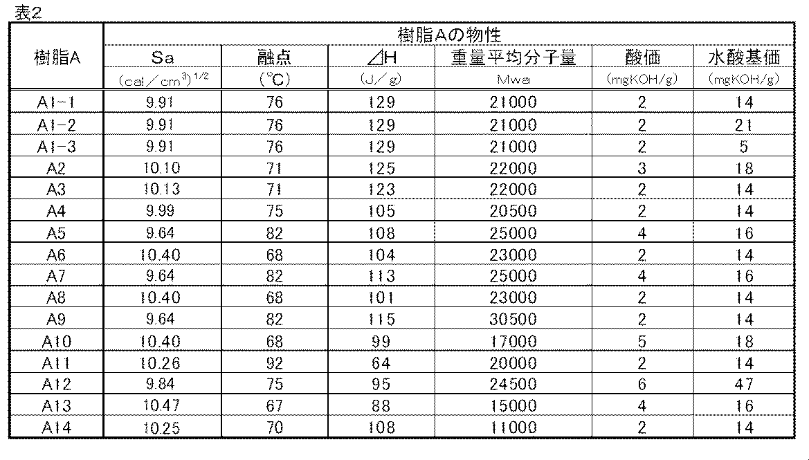
樹脂A1-1の製造例において、表1に記載のようにモノマー種、結晶核剤種およびこれらの配合量を変更した以外は樹脂A1-1の製造例と同様にして、樹脂A1-2、A1-3、A2乃至樹脂A14を得た。これらの諸物性を表2に示す。
また得られた樹脂A1-2、A1-3、A2乃至樹脂A11、樹脂A13、樹脂A14のMALDI-TOFMSのマススペクトルにおいて、樹脂Aの分子末端に結晶核剤が結合した組成のピークが確認され、分子末端と結晶核剤とが結合していることが確認された。
窒素導入管、脱水管、撹拌器及び熱電対を装備した反応槽中に、表3に示す配合量のモノマーを入れた後、触媒としてジブチル錫をモノマー総量100質量部に対して1.5質量部添加した。
次いで窒素雰囲気下において常圧で180℃まで素早く昇温した後、180℃から210℃まで10℃/時間の昇温速度で加熱しながら水を留去して重縮合を行った。
210℃に到達してから反応槽内を5kPa以下まで減圧し、210℃、5kPa以下の条件下にて重縮合を行い、樹脂B1を得た。この時の重合時間は得られる樹脂B1の軟化点が表4の値となるように調整した。得られた樹脂B1の諸物性を表4に示す。

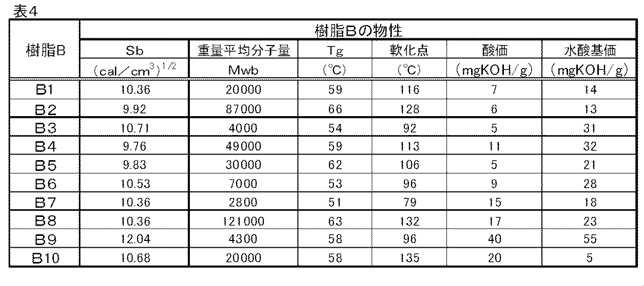
窒素導入管、脱水管、撹拌器及び熱電対を装備した反応槽中に、表3に示したモノマーのうち、無水トリメリット酸(TMA)以外を投入した後、酸化ジブチル錫を加え、窒素雰囲気下にて常圧で180℃まで素早く昇温した。
その後180℃から210℃まで10℃/時間の昇温速度で加熱しながら水を留去して重縮合を行い、210℃に到達してから反応槽内を5kPa以下まで減圧し、210℃、5kPa以下の条件下で2時間反応させた。
その後、反応槽内を一端常圧に戻して表3に示した配合量のTMAを加え、再び反応槽内を5kPa以下まで減圧した。そして210℃及び5kPa以下の条件で、表4に示す軟化点に達するまで重縮合を行って樹脂B2を製造した。得られた樹脂B2の諸物性を表4に示す。
窒素導入管、脱水管、撹拌器及び熱電対を装備した反応槽中に、表3に示したモノマーのうち、無水トリメリット酸(TMA)以外を投入した後、酸化ジブチル錫を加え、窒素雰囲気下にて常圧で170℃まで素早く昇温した。
その後170℃から195℃まで10℃/時間の昇温速度で加熱しながら水を留去して重縮合を行った。195℃に到達してから反応槽内を5kPa以下まで減圧し、減圧条件下で0.3時間反応させた。
その後、反応槽内を一端常圧に戻して表3に示した配合量のTMAを加え、再び反応槽内を5kPa以下まで減圧し、195℃及び5kPa以下の条件で、表4に示す軟化点に達するまで重縮合を行い、樹脂B3を製造した。得られた樹脂B3の諸物性を表4に示す。
樹脂B4乃至B6については、樹脂B1の製造例における原料モノマーを表3に示すように変更した以外は樹脂B1の製造例と同様にして、樹脂B4乃至B6を製造した。得られた樹脂B4乃至B6の諸物性を表4に示す。
樹脂B7乃至B8については、210℃、5kPa以下の条件下における重合時間を調整し、得られる樹脂の軟化点を表4に示すように変更した以外は、樹脂B1の製造例と同様にして樹脂B7乃至B8を製造した。得られた樹脂B7乃至B8の諸物性を表4に示す。
窒素導入管、脱水管、撹拌器及び熱電対を装備した反応槽中に、表3に示したモノマーのうち、無水トリメリット酸(TMA)以外を投入した後、重合触媒としてテトラブトキシチタネートをモノマー総量100質量部に対して3.0質量部添加した。180℃で窒素気流下に、生成する水を留去しながら8時間反応させた。ついで230℃に昇温し、窒素気流下に生成するプロピレングリコールを留去しながら反応させ、軟化点が78℃になったところで180℃に冷却し、表3に記載した量のTMAを加え、常圧密閉下1時間反応後に取り出した。取り出した樹脂を室温まで冷却後、粉砕し粒子化することで樹脂B9を得た。得られた樹脂B9の諸物性を表4に示す。
窒素導入管、脱水管、撹拌器及び熱電対を装備した反応槽中に、表3に示したモノマーのうち、無水トリメリット酸(TMA)以外を投入した後、重合触媒としてテトラブトキシチタネートをモノマー総量100質量部に対して3.0質量部添加した。230℃で窒素気流下に、生成する水を留去しながら5時間反応させ、酸価が2mgKOH/g以下になった時点で、180℃に冷却し、雰囲気下にて常圧で180℃まで素早く昇温した。
その後180℃から210℃まで10℃/時間の昇温速度で加熱しながら水を留去して重縮合を行い、210℃に到達してから反応槽内を5kPa以下まで減圧し、210℃、5kPa以下の条件下で2時間反応させた。
その後、反応槽内を一端常圧に戻して表3に示した配合量のTMAを加え、常圧密閉下2時間反応後、さらに230℃、5kPa以下の条件で反応させ、表4に示す軟化点に達するまで重縮合を行って樹脂B10を製造した。得られた樹脂B10の諸物性を表4に示す。
・樹脂A1-1 20.0質量部
・樹脂B1 80.0質量部
・カーボンブラック 5.0質量部
・フィッシャートロプシュワックス(融点105℃) 5.0質量部
・3,5-ジ-t-ブチルサリチル酸アルミニウム化合物 0.5質量部
上記材料をヘンシェルミキサー(FM-75型、三井三池化工機(株)製)で混合した後、二軸混練機(池貝鉄工(株)製PCM-30型))にて回転数3.3s-1、混練樹脂温度が樹脂Bの軟化点+10℃となるように混練機バレルの温度を調整して混練した。
得られた混練物を冷却し、ハンマーミルにて1mm以下に粗粉砕し、粗砕物を得た。得られた粗砕物を、機械式粉砕機(ターボ工業(株)製T-250)にて微粉砕した。さらに、得られた微粉砕粉末をコアンダ効果を利用した多分割分級機を用いて分級し、重量平均粒径(D4)が7.1μmの負摩擦帯電性のトナー粒子を得た。
得られたトナー粒子100質量部に、イソブチルトリメトキシシラン15質量%で表面処理した一次粒子の個数平均粒径50nmの酸化チタン微粒子1.0質量部、及びヘキサメチルジシラザン20質量%で表面処理した一次粒子の個数平均粒径16nmの疎水性シリカ微粒子0.8質量部を添加し、ヘンシェルミキサー(三井三池化工機(株)製FM-75型)で混合して、トナー1を得た。得られたトナー1の諸物性を表5に示す。

トナー1の製造例において、樹脂Aと樹脂Bの種類と、樹脂Aと樹脂Bの質量比を表5に示したように変更した以外は、トナー1の製造例と同様にしてトナー2乃至28を作成した。なおトナー27およびトナー28については、表5に記載したように樹脂Bとして複数の樹脂を用いた。得られたトナー2乃至28の諸物性を表5に示す。
本実施例において、得られたトナー1の評価に用いる画像形成装置は、市販のカラーレーザープリンタColor Laser Jet CP4525(HP社製)を用いた。この評価機において、トナーを本実施例で製造したトナー1に変更して、以下の評価を実施した。
市販のカラーレーザープリンタColor Laser Jet CP4525(HP社製)の定着器を取り出し、定着装置の定着温度、定着ニップ圧及びプロセススピードを任意に設定できるようにした外部定着器を作成した。
温度23℃、相対湿度50%環境下で、カラーレーザーコピア用紙(キヤノン製、80g/m2 A4紙)を使用し、評価に用いるカートリッジはブラックカートリッジを用いた。
すなわち、市販のブラックカートリッジから製品トナーを抜き取り、エアーブローにて内部を清掃した後、本発明のトナー1を150g充填して評価を行った。
なお、マゼンタ、イエロー、シアンの各ステーションにはそれぞれ製品トナーを抜き取り、トナー残量検知機構を無効としたマゼンタ、イエロー、およびシアンカートリッジを挿入して評価を行った。
その後、トナー載り量が0.75mg/cm2となるようにベタ黒の未定着画像を出力した。
定着器の定着温度を150℃とし、プロセススピードを240mm/secから400mm/secまでの範囲で20mm/secごとに上げていき、上記ベタ黒未定着画像の定着を行った。得られたベタ黒画像を100gの荷重をかけたシルボン紙で5往復摺擦し、摺擦前後の画像濃度の濃度低下率が10%以下となる条件を、定着可能なプロセススピードとした。そして濃度低下率10%以下を満足する最も高いプロセススピードを定着上限速度とし、この定着上限速度が速いほど、高速定着器においても低温定着性(高速低温定着性)に優れたトナーであると判断し、以下の基準で判定を行った。本発明ではCまでが許容できるレベルである。
A:定着上限速度が400mm/sec以上である。
B:定着上限速度が340mm/sec以上、400mm/sec未満である。
C:定着上限速度が240mm/sec以上、340mm/sec未満である。
D:定着上限速度が240mm/sec未満である。
上記定着試験において、定着器の定着温度を150℃とし、定着ニップ面圧を0.08MPaから0.24Mpaまでの範囲で0.02Mpaごとに上げていき、上記ベタ黒未定着画像の定着を行った。得られたベタ黒画像を100gの荷重をかけたシルボン紙で5往復摺擦し、摺擦前後の画像濃度の濃度低下率が10%以下になる条件を、定着可能なプロセススピードとした。
そして濃度低下率10%以下を満足する最も低い定着ニップ面圧を、定着下限定着ニップ面圧とし、この定着下限定着ニップ面圧が低いほど、定着ニップ面圧が低い定着器においても低温定着性(高速定着性)に優れたトナーであると判断した。そして以下の基準で判定を行った。本発明ではCまでが許容できるレベルである。
A:定着下限定着ニップ面圧が 0.10Mpa未満である。
B:定着下限定着ニップ面圧が 0.10Mpa以上、0.14Mpa未満である。
C:定着下限定着ニップ面圧が 0.14Mpa以上、0.20Mpa未満である。
D:定着下限定着ニップ面圧が 0.20Mpa以上である。
上記定着試験において、定着温度150℃、定着ニップ圧を0.25MPa、プロセススピードを200mm/secとし、上記ベタ黒未定着画像の定着を行って定着画像サンプルを得た。
得られた定着画像サンプルを2枚1組として、ベタ黒画像同士が向き合うように重ねあわせて平面台の上に置き、おもりを載せることで画像部に一定の圧力をかけた状態で、温度40℃相対湿度50%の環境試験室に7日間放置し、取り出して圧力を開放した。
このとき9組の定着画像サンプルを用意し、放置時に画像部にかける圧力(放置圧力)を0.4kPa(80g/m2A4紙500枚相当)から4.0kPa(80g/m2A4紙5000枚相当)の範囲で、0.4kPa刻みで変更して評価を行った。
そして7日間放置後の定着画像サンプルを剥がす際にブロッキングせずに剥がすことができる最大の圧力を放置上限圧力とし、放置上限圧力が高いほどトナー画像の耐熱保存安定性に優れたトナーであると判断し、以下に判定基準で評価を行った。本発明ではCまでが許容できる レベルである。
A:放置上限圧力が4.0kPa以上である。
B:放置上限圧力が3.0kPa以上4.0kPa未満である。
C:放置上限圧力が1.6kPa以上3.0kPa未満である。
D:放置上限圧力が0.4kPa以上1.6kPa未満である。
E:放置圧力0.4kPaでブロッキングし、放置上限圧力は0.4kPa未満である。
上記定着試験において、定着温度150℃、定着ニップ圧を0.25MPa、プロセススピードを200mm/secとし、上記ベタ黒未定着画像の定着を行った。得られたベタ黒画像を温度40℃、相対湿度50%の環境試験室に30日間放置した。放置後の画像を平面の台の上に置き、A4紙の長手の片側をテープで固定する。その際に、もう片側の紙がカールすることによって、平面の台と紙とで生じる角度を測定することによってカール性の評価を行った。この角度が小さい程、長期保存性が良好であると判断し、以下の基準により判定を行った。本発明ではCまでが許容できるレベルである。
A:10°未満である
B:10°以上、20°未満である。
C:20°以上、30°未満である。
D:30°以上、40°未満である。
E:40°以上である。
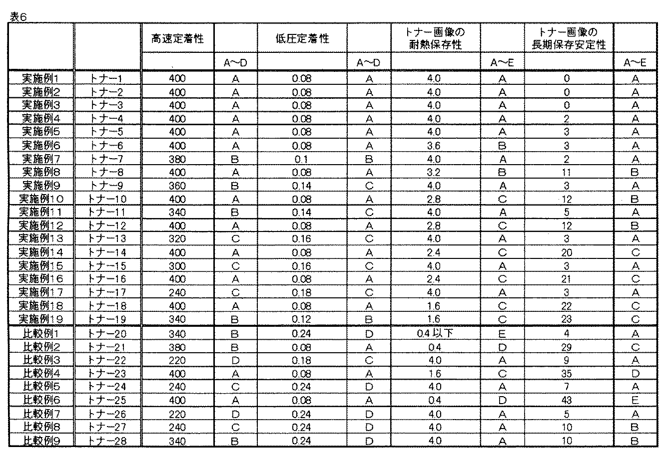
実施例1において、評価に用いるトナーを表6に示したように変更した以外は、実施例1と同様にして実施例2乃至19、比較例1乃至9の評価結果を得た。実施例2乃至19、比較例1乃至9の評価結果を表6に示す。
Claims (8)
- 樹脂A及び樹脂Bを含有する結着樹脂、ならびに着色剤を含有するトナー粒子を有するトナーであって、
(1)該樹脂Aは結晶構造をとりうる部位を有する樹脂であり、
(2)該樹脂Bは結晶構造をとりうる部位を有さない樹脂であり、
(3)入力補償型示差走査熱量計を用いた該トナーの吸熱量測定において、昇温速度100℃/分で測定した結着樹脂に由来する融解熱量をΔHhigh(J/g)、昇温速度10℃/分で測定した結着樹脂に由来する融解熱量をΔHlow(J/g)としたとき、該ΔHhighと該ΔHlowとが、下記の式1、式2の関係を満たすことを特徴とするトナー。
2≦ΔHhigh≦45 ・・・式1
3≦{(ΔHlow-ΔHhigh)/ΔHlow}×100≦70 ・・・式2 - 前記樹脂Aが、アルコール成分に由来するユニットと酸成分に由来するユニットとを有する脂肪族ポリエステル樹脂であり、
該アルコール成分に由来するユニットのうち、炭素数6以上12以下の脂肪族ジオールに由来するユニットの割合が85モル%以上であり、
該酸成分に由来するユニットのうち、炭素数6以上14以下の脂肪族ジカルボン酸に由来するユニットの割合が85モル%以上であることを特徴とする請求項1に記載のトナー。 - 該トナー中における、前記樹脂Aと前記樹脂Bとの含有量の比は、質量を基準として、樹脂A:樹脂B=5:95~40:60であることを特徴とする請求項1または2に記載のトナー。
- 前記樹脂AのSP値をSa((cal/cm3)1/2)、前記樹脂BのSP値をSb((cal/cm3)1/2)としたとき、該Saと該Sbとが、下記の式3の関係を満たすことを特徴とする請求項1乃至3のいずれか1項に記載のトナー。
-0.40≦Sb-Sa≦0.80 ・・・式3 - 前記Saが、9.00(cal/cm3)1/2以上、10.50(cal/cm3)1/2以下であることを特徴とする請求項1乃至4のいずれか1項に記載のトナー。
- 該樹脂Aの融点が、60℃以上、120℃以下であることを特徴とする請求項1乃至5のいずれか1項に記載のトナー。
- 該樹脂Bが、ポリエステル樹脂であることを特徴とする請求項1乃至6のいずれか1項に記載のトナー。
- 該樹脂Aの脂肪族ジオールに由来するユニットの炭素数をC1、該樹脂Aの脂肪族ジカルボン酸に由来するユニットの炭素数をC2としたとき、該C1と該C2とが下記式5を満たすことを特徴とする請求項2に記載のトナー。
-2≦C1-C2≦2 ・・・式5
Priority Applications (4)
| Application Number | Priority Date | Filing Date | Title |
|---|---|---|---|
| KR1020157000936A KR20150023754A (ko) | 2012-06-22 | 2013-06-20 | 토너 |
| DE112013003110.8T DE112013003110B4 (de) | 2012-06-22 | 2013-06-20 | Toner |
| CN201380032924.3A CN104395836B (zh) | 2012-06-22 | 2013-06-20 | 调色剂 |
| US14/095,963 US9040216B2 (en) | 2012-06-22 | 2013-12-03 | Toner |
Applications Claiming Priority (2)
| Application Number | Priority Date | Filing Date | Title |
|---|---|---|---|
| JP2012141016 | 2012-06-22 | ||
| JP2012-141016 | 2012-06-22 |
Related Child Applications (1)
| Application Number | Title | Priority Date | Filing Date |
|---|---|---|---|
| US14/095,963 Continuation US9040216B2 (en) | 2012-06-22 | 2013-12-03 | Toner |
Publications (1)
| Publication Number | Publication Date |
|---|---|
| WO2013190840A1 true WO2013190840A1 (ja) | 2013-12-27 |
Family
ID=49768453
Family Applications (1)
| Application Number | Title | Priority Date | Filing Date |
|---|---|---|---|
| PCT/JP2013/003837 Ceased WO2013190840A1 (ja) | 2012-06-22 | 2013-06-20 | トナー |
Country Status (6)
| Country | Link |
|---|---|
| US (1) | US9040216B2 (ja) |
| JP (1) | JP6181992B2 (ja) |
| KR (1) | KR20150023754A (ja) |
| CN (1) | CN104395836B (ja) |
| DE (1) | DE112013003110B4 (ja) |
| WO (1) | WO2013190840A1 (ja) |
Cited By (1)
| Publication number | Priority date | Publication date | Assignee | Title |
|---|---|---|---|---|
| JP2020117686A (ja) * | 2019-01-23 | 2020-08-06 | 三洋化成工業株式会社 | 結晶性ポリエステル樹脂及びトナー |
Families Citing this family (46)
| Publication number | Priority date | Publication date | Assignee | Title |
|---|---|---|---|---|
| WO2015016384A1 (en) | 2013-07-31 | 2015-02-05 | Canon Kabushiki Kaisha | Magnetic toner |
| US9715188B2 (en) | 2013-07-31 | 2017-07-25 | Canon Kabushiki Kaisha | Toner |
| WO2015170705A1 (ja) * | 2014-05-09 | 2015-11-12 | 三洋化成工業株式会社 | トナーバインダー及びトナー |
| JP6648369B2 (ja) * | 2015-03-02 | 2020-02-14 | エボニック オペレーションズ ゲーエムベーハー | Vocおよびフォギング値の低い接着剤 |
| JP6824671B2 (ja) * | 2015-12-04 | 2021-02-03 | キヤノン株式会社 | トナー |
| US10228627B2 (en) | 2015-12-04 | 2019-03-12 | Canon Kabushiki Kaisha | Toner |
| JP6991701B2 (ja) | 2015-12-04 | 2022-01-12 | キヤノン株式会社 | トナー |
| US9971263B2 (en) | 2016-01-08 | 2018-05-15 | Canon Kabushiki Kaisha | Toner |
| US9897932B2 (en) | 2016-02-04 | 2018-02-20 | Canon Kabushiki Kaisha | Toner |
| JP6904801B2 (ja) | 2016-06-30 | 2021-07-21 | キヤノン株式会社 | トナー、該トナーを備えた現像装置及び画像形成装置 |
| JP6900279B2 (ja) | 2016-09-13 | 2021-07-07 | キヤノン株式会社 | トナー及びトナーの製造方法 |
| JP6825276B2 (ja) * | 2016-09-14 | 2021-02-03 | 富士ゼロックス株式会社 | トナーセット、静電荷像現像剤セット、トナーカートリッジセット、プロセスカートリッジ、画像形成装置、及び、画像形成方法 |
| JP6825277B2 (ja) * | 2016-09-14 | 2021-02-03 | 富士ゼロックス株式会社 | トナーセット、静電荷像現像剤セット、トナーカートリッジセット、プロセスカートリッジ、画像形成装置、及び、画像形成方法 |
| US10289016B2 (en) | 2016-12-21 | 2019-05-14 | Canon Kabushiki Kaisha | Toner |
| US10295921B2 (en) | 2016-12-21 | 2019-05-21 | Canon Kabushiki Kaisha | Toner |
| US10303075B2 (en) | 2017-02-28 | 2019-05-28 | Canon Kabushiki Kaisha | Toner |
| US10295920B2 (en) | 2017-02-28 | 2019-05-21 | Canon Kabushiki Kaisha | Toner |
| US10241430B2 (en) | 2017-05-10 | 2019-03-26 | Canon Kabushiki Kaisha | Toner, and external additive for toner |
| US10545420B2 (en) | 2017-07-04 | 2020-01-28 | Canon Kabushiki Kaisha | Magnetic toner and image-forming method |
| KR102330251B1 (ko) * | 2017-08-29 | 2021-11-22 | 주식회사 엘지화학 | 폴리에테르에스테르 공중합체의 제조 방법 |
| JP2019061033A (ja) * | 2017-09-26 | 2019-04-18 | 富士ゼロックス株式会社 | 静電荷像現像用トナー、静電荷像現像用トナーの製造方法および画像形成装置 |
| US10768540B2 (en) | 2018-02-14 | 2020-09-08 | Canon Kabushiki Kaisha | External additive, method for manufacturing external additive, and toner |
| JP7066439B2 (ja) | 2018-02-14 | 2022-05-13 | キヤノン株式会社 | トナー用外添剤、トナー用外添剤の製造方法及びトナー |
| JP7001549B2 (ja) * | 2018-06-19 | 2022-01-19 | 花王株式会社 | トナー用結着樹脂組成物 |
| JP7267706B2 (ja) | 2018-10-02 | 2023-05-02 | キヤノン株式会社 | 磁性トナー |
| JP7267705B2 (ja) | 2018-10-02 | 2023-05-02 | キヤノン株式会社 | 磁性トナー |
| JP2020095083A (ja) | 2018-12-10 | 2020-06-18 | キヤノン株式会社 | トナー |
| JP7224885B2 (ja) | 2018-12-10 | 2023-02-20 | キヤノン株式会社 | トナー |
| JP7207981B2 (ja) | 2018-12-10 | 2023-01-18 | キヤノン株式会社 | トナー及びトナーの製造方法 |
| JP7433872B2 (ja) | 2018-12-28 | 2024-02-20 | キヤノン株式会社 | トナー |
| JP7443048B2 (ja) | 2018-12-28 | 2024-03-05 | キヤノン株式会社 | トナー |
| JP7391640B2 (ja) | 2018-12-28 | 2023-12-05 | キヤノン株式会社 | トナー |
| JP7504583B2 (ja) | 2018-12-28 | 2024-06-24 | キヤノン株式会社 | トナーの製造方法 |
| JP7301560B2 (ja) | 2019-03-08 | 2023-07-03 | キヤノン株式会社 | トナー |
| JP7341718B2 (ja) | 2019-05-13 | 2023-09-11 | キヤノン株式会社 | トナー |
| JP7292965B2 (ja) | 2019-05-13 | 2023-06-19 | キヤノン株式会社 | トナーおよびトナーの製造方法 |
| JP7313931B2 (ja) | 2019-06-27 | 2023-07-25 | キヤノン株式会社 | トナー |
| JP7313930B2 (ja) | 2019-06-27 | 2023-07-25 | キヤノン株式会社 | トナー |
| JP2022077739A (ja) | 2020-11-12 | 2022-05-24 | キヤノン株式会社 | トナー |
| JP7614797B2 (ja) | 2020-11-12 | 2025-01-16 | キヤノン株式会社 | トナー |
| JP7731734B2 (ja) | 2020-12-25 | 2025-09-01 | キヤノン株式会社 | トナー |
| JP7642370B2 (ja) | 2020-12-25 | 2025-03-10 | キヤノン株式会社 | トナー |
| JP7760328B2 (ja) | 2021-10-20 | 2025-10-27 | キヤノン株式会社 | 磁性トナー |
| JP7799510B2 (ja) | 2022-02-28 | 2026-01-15 | キヤノン株式会社 | トナー |
| JP7791006B2 (ja) | 2022-02-28 | 2025-12-23 | キヤノン株式会社 | トナー |
| JP7844191B2 (ja) | 2022-02-28 | 2026-04-13 | キヤノン株式会社 | トナー |
Citations (5)
| Publication number | Priority date | Publication date | Assignee | Title |
|---|---|---|---|---|
| JP2005213442A (ja) * | 2004-01-30 | 2005-08-11 | Sekisui Chem Co Ltd | 非結晶性ポリエステル |
| JP2010085969A (ja) * | 2008-09-03 | 2010-04-15 | Ricoh Co Ltd | 静電潜像現像用トナー、及びその製造方法、並びに該トナーを用いた静電潜像現像剤、トナー容器、及び画像形成装置、プロセスカートリッジ、並びに画像形成方法 |
| JP2011232738A (ja) * | 2010-04-06 | 2011-11-17 | Ricoh Co Ltd | トナー及びその製造方法 |
| JP2011242556A (ja) * | 2010-05-17 | 2011-12-01 | Sharp Corp | 赤外線レーザ定着用トナーおよび赤外線レーザ定着用トナーの製造方法 |
| JP2012058425A (ja) * | 2010-09-08 | 2012-03-22 | Ricoh Co Ltd | トナー、プレミックス剤、剤収容器、画像形成装置及び画像形成方法 |
Family Cites Families (13)
| Publication number | Priority date | Publication date | Assignee | Title |
|---|---|---|---|---|
| JP4270561B2 (ja) | 2004-10-18 | 2009-06-03 | 花王株式会社 | 電子写真用トナー |
| JP2007033773A (ja) | 2005-07-26 | 2007-02-08 | Ricoh Co Ltd | 画像形成用トナーおよび画像形成装置 |
| JP5247173B2 (ja) * | 2007-07-11 | 2013-07-24 | 三洋化成工業株式会社 | トナー用樹脂およびトナー組成物 |
| JP5084482B2 (ja) * | 2007-12-13 | 2012-11-28 | 花王株式会社 | 電子写真用トナー |
| JP5185006B2 (ja) * | 2008-07-31 | 2013-04-17 | 三洋化成工業株式会社 | 静電荷像現像用トナー |
| JP4661944B2 (ja) | 2008-11-18 | 2011-03-30 | 富士ゼロックス株式会社 | 静電荷像現像用トナーの製造方法 |
| JP5260265B2 (ja) | 2008-12-25 | 2013-08-14 | 花王株式会社 | 静電荷像現像用トナーの製造方法 |
| JP2012008530A (ja) | 2010-05-28 | 2012-01-12 | Ricoh Co Ltd | トナー及びその製造方法 |
| JP5533454B2 (ja) * | 2010-08-31 | 2014-06-25 | 株式会社リコー | トナー及び現像剤 |
| JP5760263B2 (ja) | 2010-12-29 | 2015-08-05 | 学校法人立命館 | 無段変速機及びロボット関節構造 |
| US9116448B2 (en) | 2012-06-22 | 2015-08-25 | Canon Kabushiki Kaisha | Toner |
| WO2013190828A1 (ja) | 2012-06-22 | 2013-12-27 | キヤノン株式会社 | トナー |
| EP2869126A4 (en) | 2012-06-22 | 2016-01-20 | Canon Kk | TONER |
-
2013
- 2013-06-20 CN CN201380032924.3A patent/CN104395836B/zh active Active
- 2013-06-20 DE DE112013003110.8T patent/DE112013003110B4/de active Active
- 2013-06-20 KR KR1020157000936A patent/KR20150023754A/ko not_active Ceased
- 2013-06-20 WO PCT/JP2013/003837 patent/WO2013190840A1/ja not_active Ceased
- 2013-06-21 JP JP2013131009A patent/JP6181992B2/ja active Active
- 2013-12-03 US US14/095,963 patent/US9040216B2/en active Active
Patent Citations (5)
| Publication number | Priority date | Publication date | Assignee | Title |
|---|---|---|---|---|
| JP2005213442A (ja) * | 2004-01-30 | 2005-08-11 | Sekisui Chem Co Ltd | 非結晶性ポリエステル |
| JP2010085969A (ja) * | 2008-09-03 | 2010-04-15 | Ricoh Co Ltd | 静電潜像現像用トナー、及びその製造方法、並びに該トナーを用いた静電潜像現像剤、トナー容器、及び画像形成装置、プロセスカートリッジ、並びに画像形成方法 |
| JP2011232738A (ja) * | 2010-04-06 | 2011-11-17 | Ricoh Co Ltd | トナー及びその製造方法 |
| JP2011242556A (ja) * | 2010-05-17 | 2011-12-01 | Sharp Corp | 赤外線レーザ定着用トナーおよび赤外線レーザ定着用トナーの製造方法 |
| JP2012058425A (ja) * | 2010-09-08 | 2012-03-22 | Ricoh Co Ltd | トナー、プレミックス剤、剤収容器、画像形成装置及び画像形成方法 |
Cited By (2)
| Publication number | Priority date | Publication date | Assignee | Title |
|---|---|---|---|---|
| JP2020117686A (ja) * | 2019-01-23 | 2020-08-06 | 三洋化成工業株式会社 | 結晶性ポリエステル樹脂及びトナー |
| JP7463083B2 (ja) | 2019-01-23 | 2024-04-08 | 三洋化成工業株式会社 | 結晶性ポリエステル樹脂及びトナー |
Also Published As
| Publication number | Publication date |
|---|---|
| US9040216B2 (en) | 2015-05-26 |
| KR20150023754A (ko) | 2015-03-05 |
| US20140178812A1 (en) | 2014-06-26 |
| JP6181992B2 (ja) | 2017-08-16 |
| JP2014026275A (ja) | 2014-02-06 |
| CN104395836B (zh) | 2018-12-25 |
| CN104395836A (zh) | 2015-03-04 |
| DE112013003110T5 (de) | 2015-03-12 |
| DE112013003110B4 (de) | 2022-05-12 |
Similar Documents
| Publication | Publication Date | Title |
|---|---|---|
| JP6181992B2 (ja) | トナー | |
| JP6104072B2 (ja) | トナー | |
| JP6140002B2 (ja) | トナー | |
| JP5984528B2 (ja) | トナー | |
| US9116448B2 (en) | Toner | |
| JP2015045851A (ja) | トナー | |
| US9285697B2 (en) | Toner | |
| JP6448351B2 (ja) | トナー及び二成分系現像剤 | |
| JP6376969B2 (ja) | トナーの製造方法 | |
| JP6214371B2 (ja) | トナー | |
| JP6195374B2 (ja) | トナー | |
| JP2015121580A (ja) | トナー | |
| JP6292865B2 (ja) | トナー及び二成分系現像剤 | |
| JP6195375B2 (ja) | トナー | |
| JP6659141B2 (ja) | トナー |
Legal Events
| Date | Code | Title | Description |
|---|---|---|---|
| 121 | Ep: the epo has been informed by wipo that ep was designated in this application |
Ref document number: 13806505 Country of ref document: EP Kind code of ref document: A1 |
|
| WWE | Wipo information: entry into national phase |
Ref document number: 112013003110 Country of ref document: DE Ref document number: 1120130031108 Country of ref document: DE |
|
| ENP | Entry into the national phase |
Ref document number: 20157000936 Country of ref document: KR Kind code of ref document: A |
|
| 122 | Ep: pct application non-entry in european phase |
Ref document number: 13806505 Country of ref document: EP Kind code of ref document: A1 |