WO2013073464A1 - バッテリの車載構造 - Google Patents
バッテリの車載構造 Download PDFInfo
- Publication number
- WO2013073464A1 WO2013073464A1 PCT/JP2012/079099 JP2012079099W WO2013073464A1 WO 2013073464 A1 WO2013073464 A1 WO 2013073464A1 JP 2012079099 W JP2012079099 W JP 2012079099W WO 2013073464 A1 WO2013073464 A1 WO 2013073464A1
- Authority
- WO
- WIPO (PCT)
- Prior art keywords
- battery
- battery case
- cross member
- recess
- vehicle
- Prior art date
- Legal status (The legal status is an assumption and is not a legal conclusion. Google has not performed a legal analysis and makes no representation as to the accuracy of the status listed.)
- Ceased
Links
Images



Classifications
-
- B—PERFORMING OPERATIONS; TRANSPORTING
- B60—VEHICLES IN GENERAL
- B60K—ARRANGEMENT OR MOUNTING OF PROPULSION UNITS OR OF TRANSMISSIONS IN VEHICLES; ARRANGEMENT OR MOUNTING OF PLURAL DIVERSE PRIME-MOVERS IN VEHICLES; AUXILIARY DRIVES FOR VEHICLES; INSTRUMENTATION OR DASHBOARDS FOR VEHICLES; ARRANGEMENTS IN CONNECTION WITH COOLING, AIR INTAKE, GAS EXHAUST OR FUEL SUPPLY OF PROPULSION UNITS IN VEHICLES
- B60K1/00—Arrangement or mounting of electrical propulsion units
- B60K1/04—Arrangement or mounting of electrical propulsion units of the electric storage means for propulsion
-
- B—PERFORMING OPERATIONS; TRANSPORTING
- B60—VEHICLES IN GENERAL
- B60L—PROPULSION OF ELECTRICALLY-PROPELLED VEHICLES; SUPPLYING ELECTRIC POWER FOR AUXILIARY EQUIPMENT OF ELECTRICALLY-PROPELLED VEHICLES; ELECTRODYNAMIC BRAKE SYSTEMS FOR VEHICLES IN GENERAL; MAGNETIC SUSPENSION OR LEVITATION FOR VEHICLES; MONITORING OPERATING VARIABLES OF ELECTRICALLY-PROPELLED VEHICLES; ELECTRIC SAFETY DEVICES FOR ELECTRICALLY-PROPELLED VEHICLES
- B60L1/00—Supplying electric power to auxiliary equipment of vehicles
- B60L1/003—Supplying electric power to auxiliary equipment of vehicles to auxiliary motors, e.g. for pumps, compressors
-
- B—PERFORMING OPERATIONS; TRANSPORTING
- B60—VEHICLES IN GENERAL
- B60L—PROPULSION OF ELECTRICALLY-PROPELLED VEHICLES; SUPPLYING ELECTRIC POWER FOR AUXILIARY EQUIPMENT OF ELECTRICALLY-PROPELLED VEHICLES; ELECTRODYNAMIC BRAKE SYSTEMS FOR VEHICLES IN GENERAL; MAGNETIC SUSPENSION OR LEVITATION FOR VEHICLES; MONITORING OPERATING VARIABLES OF ELECTRICALLY-PROPELLED VEHICLES; ELECTRIC SAFETY DEVICES FOR ELECTRICALLY-PROPELLED VEHICLES
- B60L3/00—Electric devices on electrically-propelled vehicles for safety purposes; Monitoring operating variables, e.g. speed, deceleration or energy consumption
- B60L3/0023—Detecting, eliminating, remedying or compensating for drive train abnormalities, e.g. failures within the drive train
- B60L3/0046—Detecting, eliminating, remedying or compensating for drive train abnormalities, e.g. failures within the drive train relating to electric energy storage systems, e.g. batteries or capacitors
-
- B—PERFORMING OPERATIONS; TRANSPORTING
- B60—VEHICLES IN GENERAL
- B60L—PROPULSION OF ELECTRICALLY-PROPELLED VEHICLES; SUPPLYING ELECTRIC POWER FOR AUXILIARY EQUIPMENT OF ELECTRICALLY-PROPELLED VEHICLES; ELECTRODYNAMIC BRAKE SYSTEMS FOR VEHICLES IN GENERAL; MAGNETIC SUSPENSION OR LEVITATION FOR VEHICLES; MONITORING OPERATING VARIABLES OF ELECTRICALLY-PROPELLED VEHICLES; ELECTRIC SAFETY DEVICES FOR ELECTRICALLY-PROPELLED VEHICLES
- B60L3/00—Electric devices on electrically-propelled vehicles for safety purposes; Monitoring operating variables, e.g. speed, deceleration or energy consumption
- B60L3/0023—Detecting, eliminating, remedying or compensating for drive train abnormalities, e.g. failures within the drive train
- B60L3/0069—Detecting, eliminating, remedying or compensating for drive train abnormalities, e.g. failures within the drive train relating to the isolation, e.g. ground fault or leak current
-
- B—PERFORMING OPERATIONS; TRANSPORTING
- B60—VEHICLES IN GENERAL
- B60L—PROPULSION OF ELECTRICALLY-PROPELLED VEHICLES; SUPPLYING ELECTRIC POWER FOR AUXILIARY EQUIPMENT OF ELECTRICALLY-PROPELLED VEHICLES; ELECTRODYNAMIC BRAKE SYSTEMS FOR VEHICLES IN GENERAL; MAGNETIC SUSPENSION OR LEVITATION FOR VEHICLES; MONITORING OPERATING VARIABLES OF ELECTRICALLY-PROPELLED VEHICLES; ELECTRIC SAFETY DEVICES FOR ELECTRICALLY-PROPELLED VEHICLES
- B60L3/00—Electric devices on electrically-propelled vehicles for safety purposes; Monitoring operating variables, e.g. speed, deceleration or energy consumption
- B60L3/04—Cutting off the power supply under fault conditions
-
- B—PERFORMING OPERATIONS; TRANSPORTING
- B60—VEHICLES IN GENERAL
- B60L—PROPULSION OF ELECTRICALLY-PROPELLED VEHICLES; SUPPLYING ELECTRIC POWER FOR AUXILIARY EQUIPMENT OF ELECTRICALLY-PROPELLED VEHICLES; ELECTRODYNAMIC BRAKE SYSTEMS FOR VEHICLES IN GENERAL; MAGNETIC SUSPENSION OR LEVITATION FOR VEHICLES; MONITORING OPERATING VARIABLES OF ELECTRICALLY-PROPELLED VEHICLES; ELECTRIC SAFETY DEVICES FOR ELECTRICALLY-PROPELLED VEHICLES
- B60L50/00—Electric propulsion with power supplied within the vehicle
- B60L50/50—Electric propulsion with power supplied within the vehicle using propulsion power supplied by batteries or fuel cells
- B60L50/52—Electric propulsion with power supplied within the vehicle using propulsion power supplied by batteries or fuel cells characterised by DC-motors
-
- B—PERFORMING OPERATIONS; TRANSPORTING
- B60—VEHICLES IN GENERAL
- B60L—PROPULSION OF ELECTRICALLY-PROPELLED VEHICLES; SUPPLYING ELECTRIC POWER FOR AUXILIARY EQUIPMENT OF ELECTRICALLY-PROPELLED VEHICLES; ELECTRODYNAMIC BRAKE SYSTEMS FOR VEHICLES IN GENERAL; MAGNETIC SUSPENSION OR LEVITATION FOR VEHICLES; MONITORING OPERATING VARIABLES OF ELECTRICALLY-PROPELLED VEHICLES; ELECTRIC SAFETY DEVICES FOR ELECTRICALLY-PROPELLED VEHICLES
- B60L50/00—Electric propulsion with power supplied within the vehicle
- B60L50/50—Electric propulsion with power supplied within the vehicle using propulsion power supplied by batteries or fuel cells
- B60L50/60—Electric propulsion with power supplied within the vehicle using propulsion power supplied by batteries or fuel cells using power supplied by batteries
- B60L50/64—Constructional details of batteries specially adapted for electric vehicles
-
- B—PERFORMING OPERATIONS; TRANSPORTING
- B60—VEHICLES IN GENERAL
- B60L—PROPULSION OF ELECTRICALLY-PROPELLED VEHICLES; SUPPLYING ELECTRIC POWER FOR AUXILIARY EQUIPMENT OF ELECTRICALLY-PROPELLED VEHICLES; ELECTRODYNAMIC BRAKE SYSTEMS FOR VEHICLES IN GENERAL; MAGNETIC SUSPENSION OR LEVITATION FOR VEHICLES; MONITORING OPERATING VARIABLES OF ELECTRICALLY-PROPELLED VEHICLES; ELECTRIC SAFETY DEVICES FOR ELECTRICALLY-PROPELLED VEHICLES
- B60L50/00—Electric propulsion with power supplied within the vehicle
- B60L50/50—Electric propulsion with power supplied within the vehicle using propulsion power supplied by batteries or fuel cells
- B60L50/60—Electric propulsion with power supplied within the vehicle using propulsion power supplied by batteries or fuel cells using power supplied by batteries
- B60L50/66—Arrangements of batteries
-
- B—PERFORMING OPERATIONS; TRANSPORTING
- B60—VEHICLES IN GENERAL
- B60L—PROPULSION OF ELECTRICALLY-PROPELLED VEHICLES; SUPPLYING ELECTRIC POWER FOR AUXILIARY EQUIPMENT OF ELECTRICALLY-PROPELLED VEHICLES; ELECTRODYNAMIC BRAKE SYSTEMS FOR VEHICLES IN GENERAL; MAGNETIC SUSPENSION OR LEVITATION FOR VEHICLES; MONITORING OPERATING VARIABLES OF ELECTRICALLY-PROPELLED VEHICLES; ELECTRIC SAFETY DEVICES FOR ELECTRICALLY-PROPELLED VEHICLES
- B60L58/00—Methods or circuit arrangements for monitoring or controlling batteries or fuel cells, specially adapted for electric vehicles
- B60L58/10—Methods or circuit arrangements for monitoring or controlling batteries or fuel cells, specially adapted for electric vehicles for monitoring or controlling batteries
- B60L58/18—Methods or circuit arrangements for monitoring or controlling batteries or fuel cells, specially adapted for electric vehicles for monitoring or controlling batteries of two or more battery modules
-
- B—PERFORMING OPERATIONS; TRANSPORTING
- B60—VEHICLES IN GENERAL
- B60L—PROPULSION OF ELECTRICALLY-PROPELLED VEHICLES; SUPPLYING ELECTRIC POWER FOR AUXILIARY EQUIPMENT OF ELECTRICALLY-PROPELLED VEHICLES; ELECTRODYNAMIC BRAKE SYSTEMS FOR VEHICLES IN GENERAL; MAGNETIC SUSPENSION OR LEVITATION FOR VEHICLES; MONITORING OPERATING VARIABLES OF ELECTRICALLY-PROPELLED VEHICLES; ELECTRIC SAFETY DEVICES FOR ELECTRICALLY-PROPELLED VEHICLES
- B60L58/00—Methods or circuit arrangements for monitoring or controlling batteries or fuel cells, specially adapted for electric vehicles
- B60L58/10—Methods or circuit arrangements for monitoring or controlling batteries or fuel cells, specially adapted for electric vehicles for monitoring or controlling batteries
- B60L58/18—Methods or circuit arrangements for monitoring or controlling batteries or fuel cells, specially adapted for electric vehicles for monitoring or controlling batteries of two or more battery modules
- B60L58/21—Methods or circuit arrangements for monitoring or controlling batteries or fuel cells, specially adapted for electric vehicles for monitoring or controlling batteries of two or more battery modules having the same nominal voltage
-
- B—PERFORMING OPERATIONS; TRANSPORTING
- B60—VEHICLES IN GENERAL
- B60L—PROPULSION OF ELECTRICALLY-PROPELLED VEHICLES; SUPPLYING ELECTRIC POWER FOR AUXILIARY EQUIPMENT OF ELECTRICALLY-PROPELLED VEHICLES; ELECTRODYNAMIC BRAKE SYSTEMS FOR VEHICLES IN GENERAL; MAGNETIC SUSPENSION OR LEVITATION FOR VEHICLES; MONITORING OPERATING VARIABLES OF ELECTRICALLY-PROPELLED VEHICLES; ELECTRIC SAFETY DEVICES FOR ELECTRICALLY-PROPELLED VEHICLES
- B60L58/00—Methods or circuit arrangements for monitoring or controlling batteries or fuel cells, specially adapted for electric vehicles
- B60L58/10—Methods or circuit arrangements for monitoring or controlling batteries or fuel cells, specially adapted for electric vehicles for monitoring or controlling batteries
- B60L58/24—Methods or circuit arrangements for monitoring or controlling batteries or fuel cells, specially adapted for electric vehicles for monitoring or controlling batteries for controlling the temperature of batteries
- B60L58/26—Methods or circuit arrangements for monitoring or controlling batteries or fuel cells, specially adapted for electric vehicles for monitoring or controlling batteries for controlling the temperature of batteries by cooling
-
- B—PERFORMING OPERATIONS; TRANSPORTING
- B60—VEHICLES IN GENERAL
- B60R—VEHICLES, VEHICLE FITTINGS, OR VEHICLE PARTS, NOT OTHERWISE PROVIDED FOR
- B60R16/00—Electric or fluid circuits specially adapted for vehicles and not otherwise provided for; Arrangement of elements of electric or fluid circuits specially adapted for vehicles and not otherwise provided for
- B60R16/02—Electric or fluid circuits specially adapted for vehicles and not otherwise provided for; Arrangement of elements of electric or fluid circuits specially adapted for vehicles and not otherwise provided for electric constitutive elements
- B60R16/04—Arrangement of batteries
-
- B—PERFORMING OPERATIONS; TRANSPORTING
- B62—LAND VEHICLES FOR TRAVELLING OTHERWISE THAN ON RAILS
- B62D—MOTOR VEHICLES; TRAILERS
- B62D21/00—Understructures, i.e. chassis frame on which a vehicle body may be mounted
- B62D21/07—Understructures, i.e. chassis frame on which a vehicle body may be mounted wide-hipped frame type, i.e. a wide box-shaped mid portion with narrower sections extending from said mid portion in both fore and aft directions
-
- H—ELECTRICITY
- H01—ELECTRIC ELEMENTS
- H01M—PROCESSES OR MEANS, e.g. BATTERIES, FOR THE DIRECT CONVERSION OF CHEMICAL ENERGY INTO ELECTRICAL ENERGY
- H01M50/00—Constructional details or processes of manufacture of the non-active parts of electrochemical cells other than fuel cells, e.g. hybrid cells
- H01M50/20—Mountings; Secondary casings or frames; Racks, modules or packs; Suspension devices; Shock absorbers; Transport or carrying devices; Holders
- H01M50/233—Mountings; Secondary casings or frames; Racks, modules or packs; Suspension devices; Shock absorbers; Transport or carrying devices; Holders characterised by physical properties of casings or racks, e.g. dimensions
- H01M50/24—Mountings; Secondary casings or frames; Racks, modules or packs; Suspension devices; Shock absorbers; Transport or carrying devices; Holders characterised by physical properties of casings or racks, e.g. dimensions adapted for protecting batteries from their environment, e.g. from corrosion
-
- H—ELECTRICITY
- H01—ELECTRIC ELEMENTS
- H01M—PROCESSES OR MEANS, e.g. BATTERIES, FOR THE DIRECT CONVERSION OF CHEMICAL ENERGY INTO ELECTRICAL ENERGY
- H01M50/00—Constructional details or processes of manufacture of the non-active parts of electrochemical cells other than fuel cells, e.g. hybrid cells
- H01M50/20—Mountings; Secondary casings or frames; Racks, modules or packs; Suspension devices; Shock absorbers; Transport or carrying devices; Holders
- H01M50/249—Mountings; Secondary casings or frames; Racks, modules or packs; Suspension devices; Shock absorbers; Transport or carrying devices; Holders specially adapted for aircraft or vehicles, e.g. cars or trains
-
- B—PERFORMING OPERATIONS; TRANSPORTING
- B60—VEHICLES IN GENERAL
- B60K—ARRANGEMENT OR MOUNTING OF PROPULSION UNITS OR OF TRANSMISSIONS IN VEHICLES; ARRANGEMENT OR MOUNTING OF PLURAL DIVERSE PRIME-MOVERS IN VEHICLES; AUXILIARY DRIVES FOR VEHICLES; INSTRUMENTATION OR DASHBOARDS FOR VEHICLES; ARRANGEMENTS IN CONNECTION WITH COOLING, AIR INTAKE, GAS EXHAUST OR FUEL SUPPLY OF PROPULSION UNITS IN VEHICLES
- B60K11/00—Arrangement in connection with cooling of propulsion units
- B60K11/06—Arrangement in connection with cooling of propulsion units with air cooling
-
- B—PERFORMING OPERATIONS; TRANSPORTING
- B60—VEHICLES IN GENERAL
- B60K—ARRANGEMENT OR MOUNTING OF PROPULSION UNITS OR OF TRANSMISSIONS IN VEHICLES; ARRANGEMENT OR MOUNTING OF PLURAL DIVERSE PRIME-MOVERS IN VEHICLES; AUXILIARY DRIVES FOR VEHICLES; INSTRUMENTATION OR DASHBOARDS FOR VEHICLES; ARRANGEMENTS IN CONNECTION WITH COOLING, AIR INTAKE, GAS EXHAUST OR FUEL SUPPLY OF PROPULSION UNITS IN VEHICLES
- B60K1/00—Arrangement or mounting of electrical propulsion units
- B60K2001/003—Arrangement or mounting of electrical propulsion units with means for cooling the electrical propulsion units
- B60K2001/005—Arrangement or mounting of electrical propulsion units with means for cooling the electrical propulsion units the electric storage means
-
- B—PERFORMING OPERATIONS; TRANSPORTING
- B60—VEHICLES IN GENERAL
- B60K—ARRANGEMENT OR MOUNTING OF PROPULSION UNITS OR OF TRANSMISSIONS IN VEHICLES; ARRANGEMENT OR MOUNTING OF PLURAL DIVERSE PRIME-MOVERS IN VEHICLES; AUXILIARY DRIVES FOR VEHICLES; INSTRUMENTATION OR DASHBOARDS FOR VEHICLES; ARRANGEMENTS IN CONNECTION WITH COOLING, AIR INTAKE, GAS EXHAUST OR FUEL SUPPLY OF PROPULSION UNITS IN VEHICLES
- B60K1/00—Arrangement or mounting of electrical propulsion units
- B60K1/04—Arrangement or mounting of electrical propulsion units of the electric storage means for propulsion
- B60K2001/0405—Arrangement or mounting of electrical propulsion units of the electric storage means for propulsion characterised by their position
- B60K2001/0438—Arrangement under the floor
-
- Y—GENERAL TAGGING OF NEW TECHNOLOGICAL DEVELOPMENTS; GENERAL TAGGING OF CROSS-SECTIONAL TECHNOLOGIES SPANNING OVER SEVERAL SECTIONS OF THE IPC; TECHNICAL SUBJECTS COVERED BY FORMER USPC CROSS-REFERENCE ART COLLECTIONS [XRACs] AND DIGESTS
- Y02—TECHNOLOGIES OR APPLICATIONS FOR MITIGATION OR ADAPTATION AGAINST CLIMATE CHANGE
- Y02E—REDUCTION OF GREENHOUSE GAS [GHG] EMISSIONS, RELATED TO ENERGY GENERATION, TRANSMISSION OR DISTRIBUTION
- Y02E60/00—Enabling technologies; Technologies with a potential or indirect contribution to GHG emissions mitigation
- Y02E60/10—Energy storage using batteries
-
- Y—GENERAL TAGGING OF NEW TECHNOLOGICAL DEVELOPMENTS; GENERAL TAGGING OF CROSS-SECTIONAL TECHNOLOGIES SPANNING OVER SEVERAL SECTIONS OF THE IPC; TECHNICAL SUBJECTS COVERED BY FORMER USPC CROSS-REFERENCE ART COLLECTIONS [XRACs] AND DIGESTS
- Y02—TECHNOLOGIES OR APPLICATIONS FOR MITIGATION OR ADAPTATION AGAINST CLIMATE CHANGE
- Y02T—CLIMATE CHANGE MITIGATION TECHNOLOGIES RELATED TO TRANSPORTATION
- Y02T10/00—Road transport of goods or passengers
- Y02T10/60—Other road transportation technologies with climate change mitigation effect
- Y02T10/70—Energy storage systems for electromobility, e.g. batteries
Definitions
- a recess extending in the vehicle width direction is formed in the battery case in order to mount a battery case storing a plurality of batteries on a vehicle body frame including a cross member extending in the vehicle width direction, and the cross member is formed in the recess.
- the present invention relates to a vehicle-mounted structure of a battery.
- Patent Document 1 The on-vehicle structure of such a battery is known from Patent Document 1 below.
- the battery case is mounted at a desired position on the vehicle body frame while providing the cross member to increase the rigidity of the vehicle body frame and avoiding interference between the battery case and the cross member.
- the middle portion in the longitudinal direction is easily deformed downward by the weight of the battery.
- the concave portion extending in the vehicle width direction is formed in the lid member of the battery case, the rigidity in the vicinity of the concave portion is lowered, and the middle portion in the front-rear direction of the battery case is further directed downward. May be easily deformed.
- a battery case formed with a recess extending in the vehicle width direction to avoid interference with the cross member of the vehicle body frame is deformed downward by the weight of the battery.
- the purpose is to prevent.
- a recess extending in the vehicle width direction is provided in the battery case so as to be mounted on a vehicle body frame having a cross member extending in the vehicle width direction.
- An in-vehicle structure for a battery, in which the cross member is formed and disposed in the recess, is provided with a fixing means for fixing the recess of the battery case to the cross member.
- the plurality of batteries are electrically connected to each other by a bus bar extending across the recess, and the battery case supports the plurality of batteries from below.
- a cover member coupled to the battery support member and covering the top of the plurality of batteries, and the fixing means fixes the battery support member and the cover member to the cross member.
- an in-vehicle structure of a battery in which a third feature is that the lid member is made of an insulating material.
- the lid member has a cooling air inlet for introducing cooling air for cooling the battery into the battery case.
- a battery mounting structure for a battery is proposed in which the concave portion is positioned below or upstream of a flow path of the cooling air toward the cooling air introduction port.
- the middle cross member 20 of the embodiment corresponds to the cross member of the present invention
- the battery tray 38 of the embodiment corresponds to the battery support member of the present invention
- the battery cover 39 of the embodiment corresponds to the lid of the present invention.
- the battery module 42 of the embodiment corresponds to the battery of the present invention
- the bolt 54 of the embodiment corresponds to the fixing member of the present invention.
- the battery case storing a plurality of batteries when the battery case storing a plurality of batteries is mounted on the vehicle body frame including the cross member extending in the vehicle width direction, the battery case is formed in the recess formed in the battery width direction. Since the cross member of the vehicle body frame is disposed, the battery case can be mounted while avoiding interference with the cross member. The middle part in the front-rear direction of the battery case that stores the heavy battery is easily deformed downward, but the battery case can be prevented from being deformed by fixing the recess of the battery case to the cross member by the fixing means.
- the battery case includes a battery support member that supports the plurality of batteries from below, and a lid member that is coupled to the battery support member and covers the top of the plurality of batteries. Since the fixing means fixes the battery support member and the lid member to the cross member, when a collision load is input to the battery case due to a vehicle collision, the fixing means increases the strength of the battery case near the recess. Further, it is possible to prevent the occurrence of a ground fault by protecting the bus bar that electrically connects a plurality of batteries across the recess.
- the lid member of the battery case is made of an insulating material, it is possible to prevent the battery terminal from being grounded to the vehicle body frame via the lid member.
- the lid member includes a cooling air inlet for introducing cooling air for cooling the battery into the battery case, and the cooling air toward the cooling air inlet is provided. Since the concave portion of the lid member is located below or upstream of the flow path, it is possible to prevent dust and water droplets contained in the cooling air from being captured in the concave portion and sucked into the battery case.
- FIG. 1 is a side view of an electric vehicle.
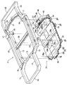
- FIG. 2 is a perspective view of the vehicle body frame and the battery pack.
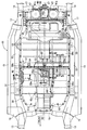
- FIG. 3 is a perspective view of the battery pack.
- (First embodiment) 4 is a view taken in the direction of the arrow 4 in FIG.
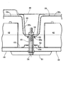
- (First embodiment) 5 is a cross-sectional view taken along line 5-5 of FIG.
- (First embodiment) 6 is a cross-sectional view taken along line 6-6 of FIG.
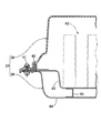
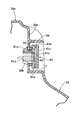
- First embodiment) 7 is a cross-sectional view taken along line 7-7 of FIG.
- First embodiment 8 is a cross-sectional view taken along line 8-8 of FIG.
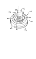
- FIG. 9 is a perspective view of the vent hole forming member.
- Body frame 20
- Middle cross member 24
- battery case 38
- battery tray 39
- Battery cover 39b
- Recess 42
- Battery module 48a Cooling air inlet
- bolt fixing means
- a body frame 11 of an electric vehicle includes a pair of left and right floor frames 12 and 12 extending in the longitudinal direction of the vehicle body, and left and right extending forward while bending upward from the front ends of the floor frames 12 and 12.
- a pair of front side frames 13, 13, a pair of left and right rear side frames 14, 14 that extend rearward while bending upward from the rear ends of the floor frames 12, 12, and the floor frames 12, 12 are disposed on the outside in the vehicle width direction.
- a pair of left and right side sills 15, 15, a pair of left and right front outriggers 16, 16 that connect the front ends of the side sills 15, 15 to the front ends of the floor frames 12, 12, and the rear ends of the side sills 15, 15 are the floor frames 12, 12.
- a pair of left and right rear outriggers 17 and 17 connected to the rear end, and a pair of left and right front side A front bumper beam 18 connecting the front ends of the frames 13, 13 in the vehicle width direction, a front cross member 19 connecting the front ends of the pair of left and right floor frames 12, 12 in the vehicle width direction, and a pair of left and right floors
- a rear bumper beam 22 that connects the rear end portions of the pair of left and right rear side frames 14, 14 in the vehicle width direction is provided.
- a battery pack 31 serving as a power source of a motor / generator 23 that is a driving source for driving an electric vehicle is supported by being suspended from the lower surface side of the vehicle body frame 11. That is, a front suspension beam 32, a middle suspension beam 33 and a rear suspension beam 34 extending in the vehicle width direction are fixed to the lower surface of the battery pack 31, and both ends of the front suspension beam 32 are a pair of left and right floor frames. 12, both ends of the middle suspension beam 33 are fixed to the rear part of the pair of left and right floor frames 12, 12, and both ends of the rear suspension beam 34 are in front of the pair of left and right rear side frames 14, 14. It fixes to the lower end of the supporting members 35 and 35 which hang down from a part.
- the vehicle width direction center portion of the front end of the battery pack 31 is supported by the front cross member 19 via the front bracket 36, and the vehicle width direction center portion of the rear end of the battery pack 31 is supported via the rear bracket 37. Supported by the cross member 21. Further, the battery pack 31 is supported on the lower surface of the middle cross member 20 at an intermediate position between the front hanging beam 32 and the middle hanging beam 33.
- the battery pack 31 includes a metal battery tray 38 and a synthetic resin battery cover 39 superimposed on the battery tray 38 from above.
- the peripheral portion of the battery tray 38 and the peripheral portion of the battery cover 39 are fastened by a large number of bolts 41 with the seal member 40 interposed therebetween (see FIG. 7), and thus the interior of the battery pack 31 is basically sealed. Space.
- On the upper surface of the battery tray 38 a plurality of battery modules 42 are stacked in which a plurality of battery cells are stacked in series.
- the battery tray 38 and the battery cover 39 constitute the battery case 24 of the present invention.
- the battery tray 38 is a structure in which an uneven middle plate 45 is sandwiched between the upper plate 43 and the lower plate 44 (see FIG. 7), and a space through which cooling air flows is formed between them. Heat exchange is performed with the battery modules 42 in contact with the upper surface of the upper plate 43, and the battery modules 42 that generate heat by charging and discharging are cooled.
- the cooling device 46 provided at the rear part of the battery pack 31 includes a pair of left and right cooling fans 47, 47 that are rotated by an electric motor (not shown).
- the lower end of the suction duct 48 disposed between the pair of left and right cooling fans 47, 47 is connected to the upstream side of the cooling air passage of the battery tray 38, and is disposed outside the pair of left and right cooling fans 47, 47 in the vehicle width direction.
- the lower ends of the pair of left and right discharge ducts 49 are connected to the downstream side of the cooling air passage of the battery tray 38. Accordingly, when the cooling fans 47 are driven, the cooling air sucked from the cooling air introduction 48a of the suction duct 48 is supplied to the inside of the battery tray 38, and flows into the battery modules 42. After exchanging heat, the exhaust air passes through the cooling fans 47 and 47 from the discharge ducts 49 and 49 and is discharged from the cooling air discharge ports 47a and 47a.
- the battery cover 39 of the battery case 24 includes a first convex part 39a, a concave part 39b, a second convex part 39c, and a third convex part 39d from the front part to the rear part.
- a plurality of battery modules 42 are accommodated in the first convex portion 39a protruding upward.
- a main switch (not shown) of the battery pack 31 is housed in a raised portion 39e that protrudes further upward from the upper surface of the first convex portion 39a, and an access for operating the main switch is placed on the upper surface of the raised portion 39e.
- a panel 39f is provided.
- a plurality of battery modules 42 are accommodated in the second convex portion 39c. Inside the third convex portion 39d, two battery modules 42 are accommodated in a position one step higher than the front portion, and a junction board (not shown) is accommodated in the rear portion.
- the recess 39b extends in a groove shape in the vehicle width direction, and the thickness of the battery pack 31 in the vertical direction is the smallest at that portion.
- three collars 50 extending in the vertical direction are arranged between the recess 39 b of the battery cover 39 and the battery tray 38.
- the lower end of the collar 50 is fixed to the lower plate 44 of the battery tray 38 and the reinforcing member 51 fixed to the lower surface thereof, and the flange 50a formed at the middle portion of the collar 50 is fixed to the upper surface of the upper plate 43 of the battery tray 38.
- a seal member 53 is disposed between a flange 50 b fixed on the lower surface of the member 52 and provided on the upper portion of the collar 50 and the lower surface of the recess 39 b of the battery cover 39.
- the terminals 42a of the battery modules 42 arranged on the front and rear sides of the recess 39b of the battery cover 39 are connected to each other by bus bars 57 bent in an inverted ⁇ shape.
- the bus bar 57 is obtained by covering a metal wire 58 with a synthetic resin covering material 59, and both ends thereof are fixed to terminals 42 a and 42 a of the battery modules 42 and 42 with bolts 60 and 60.
- vent hole forming members 61 are left and right on a wall surface 39g that rises substantially vertically on the rear side of the raised portion 39e of the first convex portion 39a of the battery cover 39. Juxtaposed in the direction.
- the vent hole forming member 61 includes a disc-shaped main body portion 61a, a disc-shaped cover portion 61c connected to the upper portion of the main body portion 61a via a connecting portion 61b and facing the surface side of the main body portion 61a, Three claw portions 61d...
- a ventilation member 62 Projecting from the back surface side of the main body portion 61a, and a ventilation member 62 such as Gore-Tex (registered trademark) is provided in a circular ventilation hole 61e formed in the center of the main body portion 61a. It is done.
- the ventilation member 62 has a function of blocking the passage of moisture and dust by allowing air to pass therethrough.
- the vent hole forming member 61 is fixed to the opening 30h formed in the wall surface 39g of the battery cover 39 by three claw portions 61d with the O-ring 63 interposed therebetween.
- the upper portion of the vent hole forming member 61 fixed to the wall surface 39g is covered with a flange 39i protruding rearward from the wall surface 39g.
- both ends of the front suspension beam 32 and both ends of the middle suspension beam 33 are fixed to the floor frames 12, 12. Both ends are fixed to the rear side frames 14 and 14 via support members 35 and 35, and the front bracket 36 and the rear bracket 37 are fixed to the front cross member 19 and the rear cross member 21, respectively.
- the concave portion 39 b is formed in the middle portion in the front-rear direction of the battery cover 39 of the battery pack 31, the middle cross member 20 of the vehicle body frame 11 is attached to the battery cover 39 when the battery pack 31 is attached to the vehicle body frame 11.
- the battery pack 31 can be attached without interfering with the vehicle body frame 11 by fitting into the recess 39b.
- the battery case 24 has a shape that is long in the longitudinal direction of the vehicle body, and the battery cover 39 made of synthetic resin hardly contributes to the rigidity of the battery case 24, so that the battery tray 38 having a small thickness depends on the weight of the battery modules 42. Due to the deformation, there is a problem that the middle part of the battery case 24 is bent downward.
- the battery case 24 is fixed to the lower surface of the middle cross member 20 at the position of the recess 39b of the battery cover 39 with the three bolts 54, the weight of the battery pack 31 is highly rigid. By supporting the middle cross member 20 that is a strength member of the battery case 24, it is possible to reliably prevent the middle portion of the battery case 24 from bending downward.
- the bolts 54 pass through both the battery tray 38 and the battery cover 39 of the battery case 24 and are fixed to the middle cross member 20, when the collision load is input to the battery case 24 due to a vehicle collision, the bolts 54.
- the bus bar 57 that electrically connects the front and rear battery modules 42 across the recess 39b is protected and the occurrence of a ground fault is prevented.
- the battery cover 39 of the battery case 24 is disposed at a position close to the terminals 42a of the battery modules 42, but since the battery cover 39 is made of non-conductive synthetic resin, the terminals 42a of the battery modules 42 are used. Can be prevented from being grounded to the vehicle body frame 11 via the battery cover 39.
- the cooling air flowing along the upper surface of the battery cover 39 flows from the cooling air introduction port 48 a that opens to the front surface of the suction duct 48 that constitutes a part of the battery cover 39.
- the battery cover 39 in front of the cooling air introduction port 48a has a second recess 39d extending in the vehicle width direction, so that dust and water droplets contained in the cooling air flowing along the upper surface of the battery cover 39 are removed. It can be captured in the second recess 39 d and prevented from being sucked into the battery case 24.
- the battery case 24 is a sealed container in which the battery cover 39 is coupled to the battery tray 38 via the seal member 40. Therefore, when the battery modules 42 accommodated therein generate heat due to charge / discharge, the internal pressure increases, When cooled by stopping the discharge, the internal pressure decreases. Therefore, due to the deformation of the battery cover 39 and the increase of the pressure in the water intrusion direction into the sealing member 40 due to the decrease in the internal pressure of the battery case 24, the sealing function of the sealing member 40 is reduced, and water and dust are collected inside the battery case 24. There is a possibility of entering.
- the ventilation holes 61e of the ventilation hole forming members 61 are provided with ventilation members 62 that do not allow moisture or dust to pass therethrough, and thus prevent moisture and dust from entering the inside of the battery case 24. can do.
- the air hole forming member 61 is provided on the wall surface 39g behind the first convex portion 39a of the battery cover 39, that is, the wall surface 39g facing the downstream side in the flow direction of the cooling air, dust and water droplets contained in the cooling air are generated. It is possible to make it difficult to enter the inside of the battery case 24 from the vent hole forming members 61.
- the wall surface 39g stands up in a substantially vertical direction and the flange portion 39i protrudes upward, rainwater or the like flowing along the wall surface 39g hardly flows into the battery case 24 through the vent hole forming member 61. can do.
- the battery case 24 is shielded so as to block a line connecting the cooling air introduction port 48a opening forward of the cooling device 46 and the vent hole forming members 61 provided on the rear wall surface 39g of the first convex portion 39a. Since the 3rd convex part 39d stands, it is prevented that the negative pressure which generate
- the battery cover 39 according to the embodiment is formed of a single member, it may be divided into two parts at the position of the recess 39b.
- the fixing member of the present invention is not limited to the bolt 54 of the embodiment, and any fixing member such as a clamp or a clip can be adopted.
- the recess 39b is disposed below the flow path through which the cooling air flows into the cooling air introduction port 48a.
- the upstream side of the flow path of the cooling air flowing into the cooling air introduction port 48a that is, the cooling air. If the recess 39b is arranged on the flow path of the same, the same effect can be achieved even if it is not necessarily arranged below.
Landscapes
- Engineering & Computer Science (AREA)
- Mechanical Engineering (AREA)
- Transportation (AREA)
- Power Engineering (AREA)
- Life Sciences & Earth Sciences (AREA)
- Sustainable Development (AREA)
- Sustainable Energy (AREA)
- Chemical & Material Sciences (AREA)
- Combustion & Propulsion (AREA)
- Chemical Kinetics & Catalysis (AREA)
- Electrochemistry (AREA)
- General Chemical & Material Sciences (AREA)
- Aviation & Aerospace Engineering (AREA)
- Arrangement Or Mounting Of Propulsion Units For Vehicles (AREA)
- Battery Mounting, Suspending (AREA)
- Cooling, Air Intake And Gas Exhaust, And Fuel Tank Arrangements In Propulsion Units (AREA)
Abstract
Description
20 ミドルクロスメンバ(クロスメンバ)
24 バッテリケース
38 バッテリトレー(バッテリ支持部材)
39 バッテリカバー(蓋部材)
39b 凹部
42 バッテリモジュール(バッテリ)
48a 冷却空気導入口
54 ボルト(固定手段)
57 バスバー
Claims (4)
- 複数のバッテリ(42)を収納するバッテリケース(24)を車幅方向に延びるクロスメンバ(20)を備える車体フレーム(11)に搭載すべく、前記バッテリケース(24)に車幅方向に延びる凹部(39b)を形成し、前記凹部(39b)内に前記クロスメンバ(20)を配置するバッテリの車載構造において、
前記バッテリケース(24)の凹部(39b)を前記クロスメンバ(20)に固定する固定手段(54)を備えることを特徴とするバッテリの車載構造。 - 前記複数のバッテリ(42)は前記凹部(39b)を跨いで延びるバスバー(57)によって相互に電気的に接続され、前記バッテリケース(24)は、前記複数のバッテリ(42)を下方から支持するバッテリ支持部材(38)と、前記バッテリ支持部材(38)に結合されて前記複数のバッテリ(42)の上方を覆う蓋部材(39)とからなり、前記固定手段(54)は前記バッテリ支持部材(38)および前記蓋部材(39)を前記クロスメンバ(20)に固定することを特徴とする、請求項1に記載のバッテリの車載構造。
- 前記蓋部材(39)は絶縁性材料で構成されることを特徴とする、請求項1または請求項2に記載のバッテリの車載構造。
- 前記蓋部材(39)は前記バッテリ(42)を冷却するための冷却空気を前記バッテリケース(24)の内部に導入する冷却空気導入口(48a)を備え、前記凹部(39b)は、前記冷却空気導入口(48a)に向かう冷却空気の流路の下方あるいは上流側に位置することを特徴とする、請求項1~請求項3の何れか1項に記載のバッテリの車載構造。
Priority Applications (2)
| Application Number | Priority Date | Filing Date | Title |
|---|---|---|---|
| US14/353,302 US9227582B2 (en) | 2011-11-14 | 2012-11-09 | Vehicle mounting structure for batteries |
| JP2013544241A JP5734453B2 (ja) | 2011-11-14 | 2012-11-09 | バッテリの車載構造 |
Applications Claiming Priority (2)
| Application Number | Priority Date | Filing Date | Title |
|---|---|---|---|
| JP2011-248429 | 2011-11-14 | ||
| JP2011248429 | 2011-11-14 |
Publications (1)
| Publication Number | Publication Date |
|---|---|
| WO2013073464A1 true WO2013073464A1 (ja) | 2013-05-23 |
Family
ID=48429524
Family Applications (1)
| Application Number | Title | Priority Date | Filing Date |
|---|---|---|---|
| PCT/JP2012/079099 Ceased WO2013073464A1 (ja) | 2011-11-14 | 2012-11-09 | バッテリの車載構造 |
Country Status (3)
| Country | Link |
|---|---|
| US (1) | US9227582B2 (ja) |
| JP (1) | JP5734453B2 (ja) |
| WO (1) | WO2013073464A1 (ja) |
Cited By (19)
| Publication number | Priority date | Publication date | Assignee | Title |
|---|---|---|---|---|
| CN103600644A (zh) * | 2013-10-31 | 2014-02-26 | 深圳精智机器有限公司 | 电池锁止机构 |
| JP2015106531A (ja) * | 2013-12-02 | 2015-06-08 | 三菱自動車工業株式会社 | バッテリセル固定装置 |
| JP2015150927A (ja) * | 2014-02-12 | 2015-08-24 | 日産自動車株式会社 | バッテリの車載構造 |
| JP2015223959A (ja) * | 2014-05-28 | 2015-12-14 | 三菱自動車工業株式会社 | 車両のバッテリ取付構造 |
| JP2015224027A (ja) * | 2014-05-26 | 2015-12-14 | ドクター エンジニール ハー ツェー エフ ポルシェ アクチエンゲゼルシャフトDr. Ing. h.c.F. Porsche Aktiengesellschaft | 自動車用床下ユニット |
| KR20170052831A (ko) * | 2015-11-05 | 2017-05-15 | 주식회사 엘지화학 | 보강 지지부재를 포함하고 있는 전지팩 |
| JP2017193288A (ja) * | 2016-04-21 | 2017-10-26 | トヨタ自動車株式会社 | 車両のバッテリ搭載構造 |
| JP2017196958A (ja) * | 2016-04-26 | 2017-11-02 | トヨタ自動車株式会社 | 車両のバッテリ搭載構造 |
| CN108016501A (zh) * | 2017-12-28 | 2018-05-11 | 江苏易行车业有限公司 | 一种新型的电动汽车模块化结构 |
| JP2018532244A (ja) * | 2016-01-12 | 2018-11-01 | エルジー・ケム・リミテッド | デバイスに対する搭載空間が最小化された電池パック |
| JP2019003886A (ja) * | 2017-06-19 | 2019-01-10 | 本田技研工業株式会社 | バッテリパック |
| US10322616B2 (en) * | 2014-01-29 | 2019-06-18 | Perpetual V2G Systems Limited | Vehicular refrigerator system |
| CN111312943A (zh) * | 2018-12-11 | 2020-06-19 | 丰田自动车株式会社 | 电池组框架 |
| JP2021512009A (ja) * | 2018-01-31 | 2021-05-13 | ティーピーアイ コンポジッツ,インコーポレーティッド | 複合バッテリ筐体 |
| JP2022544822A (ja) * | 2020-01-03 | 2022-10-21 | エルジー エナジー ソリューション リミテッド | 改善された締結構造を有するバッテリーパック及びそれを含む自動車 |
| JP2022545705A (ja) * | 2020-01-03 | 2022-10-28 | エルジー エナジー ソリューション リミテッド | 改善された結合構造を有するバッテリーパック及びそれを含む自動車 |
| KR20240003256A (ko) * | 2022-06-30 | 2024-01-08 | 주식회사 동희산업 | 배터리케이스용 센터파이프 조립체 |
| JP2025014536A (ja) * | 2023-07-19 | 2025-01-30 | トヨタ自動車株式会社 | フレーム車両 |
| WO2025211536A1 (ko) * | 2024-04-02 | 2025-10-09 | 주식회사 엘지에너지솔루션 | 모듈커버, 배터리팩 및 차량 |
Families Citing this family (136)
| Publication number | Priority date | Publication date | Assignee | Title |
|---|---|---|---|---|
| DE102010003257B4 (de) * | 2010-03-25 | 2022-07-07 | Bayerische Motoren Werke Aktiengesellschaft | Vorrichtung zur Kondensatabfuhr für ein gegenüber der Umgebung abgeschlossenes Gehäuse eines Kraftfahrzeugs, Gehäuse und Kraftfahrzeug |
| US20120151843A1 (en) * | 2010-12-20 | 2012-06-21 | Tesla Motors, Inc. | Vehicle Door Secondary Sealing System |
| JP5503087B2 (ja) * | 2011-11-14 | 2014-05-28 | 本田技研工業株式会社 | 電動車両用バッテリパックおよびバッテリパックの搭載構造 |
| CA2926291C (en) | 2012-10-19 | 2022-04-05 | Chris FORSBERG | Systems and methods for mounting a fuel system |
| WO2014167978A1 (ja) * | 2013-04-12 | 2014-10-16 | 日産自動車株式会社 | 非接触給電装置 |
| JP5811168B2 (ja) * | 2013-12-25 | 2015-11-11 | トヨタ自動車株式会社 | 車両用電池搭載構造 |
| JP5846193B2 (ja) * | 2013-12-25 | 2016-01-20 | トヨタ自動車株式会社 | 車両用電池搭載構造 |
| DE102014108160A1 (de) * | 2014-06-11 | 2015-12-17 | Dr. Ing. H.C. F. Porsche Aktiengesellschaft | Unterbodeneinheit für ein Kraftfahrzeug |
| JP6167096B2 (ja) * | 2014-11-18 | 2017-07-19 | 本田技研工業株式会社 | 車両用バッテリユニット |
| US10358169B2 (en) * | 2015-03-06 | 2019-07-23 | Ford Global Technologies, Llc | Coverless battery assembly for electrified vehicle |
| US11211655B2 (en) * | 2015-03-31 | 2021-12-28 | Ford Global Technologies, Llc | Vehicle enclosure for preventing access to high voltage components |
| JP6436841B2 (ja) * | 2015-04-09 | 2018-12-12 | 株式会社クボタ | 電動作業車両 |
| WO2016210329A1 (en) * | 2015-06-25 | 2016-12-29 | Agility Fuel Systems, Inc. | Tailgate fuel system mounting system |
| DE102015111749A1 (de) | 2015-07-20 | 2017-01-26 | Dr. Ing. H.C. F. Porsche Aktiengesellschaft | Batterieeinrichtung und Verfahren |
| KR101794266B1 (ko) * | 2016-01-07 | 2017-11-07 | 삼성에스디아이 주식회사 | 슬라이드 조립에 적용되는 배터리 모듈용 트레이 |
| US10516145B2 (en) * | 2016-01-26 | 2019-12-24 | Ford Global Technologies, Llc | Battery pack array retention |
| JP6421766B2 (ja) * | 2016-02-02 | 2018-11-14 | トヨタ自動車株式会社 | フレーム車の骨格構造 |
| US9758030B2 (en) | 2016-02-09 | 2017-09-12 | NextEv USA, Inc. | Replaceable battery assembly having a latching mechanism |
| US10017037B2 (en) * | 2016-02-09 | 2018-07-10 | Nio Usa, Inc. | Vehicle having a battery pack directly attached to the cross rails of a frame structure |
| DE102016202909B4 (de) * | 2016-02-25 | 2025-10-16 | Bayerische Motoren Werke Aktiengesellschaft | Energiespeichergehäuse, Fahrzeug mit einem Energiespeichergehäuse und Set aus Energiespeichergehäusen |
| US9722223B1 (en) * | 2016-03-02 | 2017-08-01 | Ford Global Technologies, Llc | Battery pack retention assembly and method |
| JP6255438B2 (ja) * | 2016-03-17 | 2017-12-27 | 本田技研工業株式会社 | バッテリユニット及び車両 |
| JP6451685B2 (ja) * | 2016-04-21 | 2019-01-16 | トヨタ自動車株式会社 | 車両のバッテリ搭載構造 |
| KR101795399B1 (ko) * | 2016-06-22 | 2017-11-10 | 현대자동차 주식회사 | 전기자동차용 언더바디 |
| US10632857B2 (en) | 2016-08-17 | 2020-04-28 | Shape Corp. | Battery support and protection structure for a vehicle |
| US20180105062A1 (en) | 2016-10-14 | 2018-04-19 | Inevit, Inc. | Battery module compartment chamber and battery module mounting area of an energy storage system and method thereof |
| US10381621B2 (en) * | 2016-11-01 | 2019-08-13 | Ford Global Technologies, Llc | Traction battery energy absorbing method and assembly |
| US9884545B1 (en) * | 2016-11-01 | 2018-02-06 | Ford Global Technologies, Llc | Traction battery mounting assembly and securing method |
| US10431791B2 (en) * | 2016-11-01 | 2019-10-01 | Ford Global Technologies, Llc | Traction battery pack shield and shielding method |
| JP6631472B2 (ja) * | 2016-11-07 | 2020-01-15 | トヨタ自動車株式会社 | 車両下部構造 |
| JP6597562B2 (ja) * | 2016-11-08 | 2019-10-30 | トヨタ自動車株式会社 | 車両下部構造 |
| JP6561969B2 (ja) * | 2016-11-08 | 2019-08-21 | トヨタ自動車株式会社 | 車両下部構造 |
| US20180170209A1 (en) * | 2016-12-16 | 2018-06-21 | Ford Global Technologies, Llc | Traction battery pack service panel |
| CN110383526A (zh) | 2017-01-04 | 2019-10-25 | 形状集团 | 节点模块化的车辆电池托盘结构 |
| US10112470B2 (en) * | 2017-01-11 | 2018-10-30 | GM Global Technology Operations LLC | Structural enhancements of an electric vehicle |
| US9926017B1 (en) * | 2017-01-24 | 2018-03-27 | GM Global Technology Operations LLC | Structural enhancements of an electric vehicle |
| US10272759B2 (en) * | 2017-01-30 | 2019-04-30 | GM Global Technology Operations LLC | Structural enhancements of an electric vehicle |
| CA3055732C (en) | 2017-02-01 | 2024-01-23 | Agility Fuel Systems Llc | Tailgate fuel storage system |
| DE102017206988A1 (de) * | 2017-04-26 | 2018-10-31 | Mahle Lnternational Gmbh | Akkumulatoranordnung |
| WO2018213383A1 (en) * | 2017-05-16 | 2018-11-22 | Shape Corp. | Vehicle battery tray with integrated battery retention and support features |
| US10483510B2 (en) | 2017-05-16 | 2019-11-19 | Shape Corp. | Polarized battery tray for a vehicle |
| US10886513B2 (en) | 2017-05-16 | 2021-01-05 | Shape Corp. | Vehicle battery tray having tub-based integration |
| DE102017209524B4 (de) * | 2017-06-07 | 2024-11-21 | Volkswagen Aktiengesellschaft | Befestigungsanordnung zur Befestigung von Batteriemodulen in einem Batteriekasten und Traktionsbatterie für ein Kraftfahrzeug |
| CN109204560B (zh) * | 2017-06-30 | 2021-02-23 | 比亚迪股份有限公司 | 电动汽车及其车身结构 |
| US12347879B2 (en) | 2017-09-13 | 2025-07-01 | Shape Corp. | Vehicle battery tray with tubular peripheral wall |
| CN111108015A (zh) | 2017-09-13 | 2020-05-05 | 形状集团 | 具有管状外围壁的车辆电池托盘 |
| WO2019071013A1 (en) | 2017-10-04 | 2019-04-11 | Shape Corp. | BATTERY SUPPORT BOTTOM ASSEMBLY FOR ELECTRIC VEHICLES |
| JP6859933B2 (ja) * | 2017-11-17 | 2021-04-14 | トヨタ自動車株式会社 | 車両用電池ケース及びその製造方法 |
| KR102319537B1 (ko) * | 2017-12-20 | 2021-10-29 | 주식회사 엘지에너지솔루션 | 배터리 모듈, 이를 포함하는 배터리 팩 및 자동차 |
| EP3759761B1 (en) | 2018-03-01 | 2026-04-08 | Shape Corp. | Cooling system integrated with vehicle battery tray |
| JP6996352B2 (ja) * | 2018-03-06 | 2022-01-17 | トヨタ自動車株式会社 | 車両の下部車体構造 |
| JP6984494B2 (ja) * | 2018-03-07 | 2021-12-22 | トヨタ自動車株式会社 | 車体構造 |
| US11688910B2 (en) | 2018-03-15 | 2023-06-27 | Shape Corp. | Vehicle battery tray having tub-based component |
| DE102018106399A1 (de) * | 2018-03-19 | 2019-09-19 | Muhr Und Bender Kg | Gehäuseanordnung zur Aufnahme elektrischer Speichermittel und Verfahren zur Herstellung einer Gehäuseanordnung |
| WO2019178912A1 (zh) * | 2018-03-22 | 2019-09-26 | 深圳市大富科技股份有限公司 | 一种电动车及其底盘组件、压持块组件和电池组件 |
| US10688854B2 (en) * | 2018-03-26 | 2020-06-23 | Ford Global Technologies, Llc | Electric vehicle with integrated battery and floor assembly |
| CN108598324A (zh) * | 2018-06-05 | 2018-09-28 | 华霆(合肥)动力技术有限公司 | 电池箱体及电动车 |
| US12330515B2 (en) | 2018-06-25 | 2025-06-17 | Magna International Inc. | Battery frame |
| DE102018213009A1 (de) * | 2018-08-03 | 2020-02-06 | Bayerische Motoren Werke Aktiengesellschaft | Befestigungsanordnung für eine Fahrzeugbatterie an einer Karosserie eines Kraftfahrzeugs sowie Verfahren zur Montage einer Fahrzeugbatterie in einem Kraftfahrzeug |
| CA3110459C (en) * | 2018-08-24 | 2024-06-18 | Hexagon Purus North America Holdings Inc. | Battery system for heavy duty vehicles |
| JP7044013B2 (ja) * | 2018-08-27 | 2022-03-30 | トヨタ自動車株式会社 | 車両下部構造 |
| JP6683777B2 (ja) * | 2018-08-28 | 2020-04-22 | 本田技研工業株式会社 | バッテリケースの固定構造 |
| WO2020044792A1 (ja) * | 2018-08-28 | 2020-03-05 | 本田技研工業株式会社 | バッテリパックの配置構造 |
| JP2020035717A (ja) * | 2018-08-31 | 2020-03-05 | 本田技研工業株式会社 | 電池パック及び電池パックの製造方法 |
| US11059361B2 (en) | 2018-09-04 | 2021-07-13 | Ford Global Technologies, Llc | High voltage battery pack support and isolation for electrified vehicles |
| US10752072B2 (en) | 2018-09-05 | 2020-08-25 | Ford Global Technologies, Llc | Electrified vehicle with vibration isolator within frame and corresponding method |
| US10618425B2 (en) * | 2018-09-10 | 2020-04-14 | Ford Global Technologies, Llc | High voltage battery pack mounting systems for electrified vehicles |
| JP6734334B2 (ja) * | 2018-09-14 | 2020-08-05 | 本田技研工業株式会社 | 車両の下部構造 |
| DE102018215954B4 (de) * | 2018-09-19 | 2020-06-04 | Audi Ag | Kraftfahrzeug und Batterie |
| US11007899B2 (en) * | 2018-10-23 | 2021-05-18 | Chongqing Jinkang New Energy Vehicle Co., Ltd | Mounting structures for battery packs in electric vehicles |
| CN109560234A (zh) * | 2018-12-14 | 2019-04-02 | 蜂巢能源科技有限公司 | 电池包的壳体结构、电池包和车辆 |
| DE102018132255A1 (de) * | 2018-12-14 | 2020-06-18 | Bayerische Motoren Werke Aktiengesellschaft | Energiespeicher-Bodengruppe für einen Kraftwagenrohbau |
| JP7052715B2 (ja) * | 2018-12-28 | 2022-04-12 | トヨタ自動車株式会社 | 車両下部構造 |
| WO2020146730A1 (en) * | 2019-01-10 | 2020-07-16 | Quadrobot Inc. | Integrated vehicle frame |
| KR102610755B1 (ko) * | 2019-01-22 | 2023-12-07 | 현대자동차주식회사 | 차량용 플로어 구조 |
| DE102019102049A1 (de) * | 2019-01-28 | 2020-07-30 | Bayerische Motoren Werke Aktiengesellschaft | Kraftfahrzeug mit einer Bodenbaugruppe und einer Speicherzellenbaugruppe |
| US11440399B2 (en) | 2019-03-22 | 2022-09-13 | Agility Fuel Systems Llc | Fuel system mountable to a vehicle frame |
| MX2021011312A (es) | 2019-03-22 | 2022-01-06 | Agility Fuel Systems Llc | Sistema de combustible montable en un riel del bastidor del vehículo. |
| KR102645055B1 (ko) | 2019-04-10 | 2024-03-08 | 현대자동차주식회사 | 차량용 센터플로어 구조 |
| US11040610B2 (en) | 2019-04-19 | 2021-06-22 | Hexagon Purus North America Holdings Inc. | Electric powertrain system for heavy duty vehicles |
| WO2020215023A1 (en) | 2019-04-19 | 2020-10-22 | Hexagon Purus North America Holdings Inc. | Electric front end accessory devices assembly |
| US20200347992A1 (en) | 2019-05-02 | 2020-11-05 | Agility Fuel Systems Llc | Polymeric liner based gas cylinder with reduced permeability |
| DE102019113699A1 (de) * | 2019-05-22 | 2020-11-26 | Bayerische Motoren Werke Aktiengesellschaft | Kraftfahrzeug mit einer Kraftfahrzeugkarosserie und einer Speicherzellenbaugruppe |
| CN209747594U (zh) | 2019-05-29 | 2019-12-06 | 宁德时代新能源科技股份有限公司 | 电池箱体、电池包以及车辆 |
| DE102019123846A1 (de) * | 2019-09-05 | 2021-03-11 | Bayerische Motoren Werke Aktiengesellschaft | Energiespeicher-Bodengruppe für einen Kraftwagen |
| DE102019123845A1 (de) * | 2019-09-05 | 2021-03-11 | Bayerische Motoren Werke Aktiengesellschaft | Energiespeicher-Bodengruppe für einen Kraftwagen |
| DE102019123844A1 (de) | 2019-09-05 | 2021-03-11 | Bayerische Motoren Werke Aktiengesellschaft | Fahrzeugboden für eine Energiespeicher-Bodengruppe eines Kraftwagens |
| US20220336900A1 (en) * | 2019-09-06 | 2022-10-20 | Miguel MERINO | Lightweight battery housing assembly |
| MX2022005982A (es) | 2019-11-21 | 2022-09-02 | Tesla Inc | Sistema de almacenamiento de energia integrado. |
| CA3161967C (en) | 2019-11-26 | 2025-05-13 | Hexagon Purus North America Holdings Inc. | POWER DISTRIBUTION FOR ELECTRIC VEHICLES AND MOTOR CONTROL MODULE |
| US11515600B2 (en) * | 2019-12-09 | 2022-11-29 | GM Global Technology Operations LLC | Electric vehicle battery enclosure with sealant and seal bead height maintenance |
| JP7264070B2 (ja) * | 2020-01-20 | 2023-04-25 | トヨタ自動車株式会社 | 蓄電装置の搭載構造 |
| US11258128B2 (en) * | 2020-01-22 | 2022-02-22 | Ford Global Technologies, Llc | Battery pack reinforcement assemblies |
| DE102020102480A1 (de) | 2020-01-31 | 2021-08-05 | Bayerische Motoren Werke Aktiengesellschaft | Energiespeicher-Bodengruppe für einen elektrisch antreibbaren Kraftwagen |
| US11541935B2 (en) * | 2020-03-30 | 2023-01-03 | Metalsa S.A. De C.V. | Vehicle frame |
| US11186321B2 (en) | 2020-04-13 | 2021-11-30 | Hyundai Motor Company | Load absorbing structure for vehicle |
| KR102453341B1 (ko) * | 2020-06-15 | 2022-10-11 | 현대모비스 주식회사 | 차량용 배터리 마운트 구조 |
| DE102020117317B3 (de) * | 2020-07-01 | 2021-11-18 | Dr. Ing. H.C. F. Porsche Aktiengesellschaft | Schweller-Rahmen-Anordnung sowie eine Fahrzeugkarosserieanordnung mit einer derartigen Schweller-Rahmen-Anordnung |
| US11926207B2 (en) | 2020-10-09 | 2024-03-12 | Hexagon Purus North America Holdings Inc. | Battery and auxiliary components for vehicle trailer |
| US11745573B2 (en) * | 2020-10-22 | 2023-09-05 | Ford Global Technologies, Llc | Integrated frame and battery pack structure for electric vehicles |
| CN114447498B (zh) * | 2020-10-30 | 2023-07-11 | 比亚迪股份有限公司 | 电池包和具有其的车辆 |
| CN114571974B (zh) * | 2020-11-30 | 2024-02-06 | 本田技研工业株式会社 | 电池支承结构 |
| CA3205080A1 (en) | 2020-12-11 | 2022-06-16 | Hexagon Purus North America Holdings Inc. | Trailer hookup breakaway mitigation systems and methods |
| DE102020133961A1 (de) * | 2020-12-17 | 2022-06-23 | Bayerische Motoren Werke Aktiengesellschaft | Energiespeicher-Bodengruppe für einen elektrisch antreibbaren Kraftwagen |
| DE102021103988A1 (de) * | 2021-02-19 | 2022-08-25 | Dr. Ing. H.C. F. Porsche Aktiengesellschaft | Kraftfahrzeugboden und Kraftfahrzeug mit einem Kraftfahrzeugboden |
| JP7694160B2 (ja) * | 2021-06-01 | 2025-06-18 | マツダ株式会社 | 車体構造 |
| US12319133B2 (en) * | 2021-08-01 | 2025-06-03 | Vanderhall Motor Works Inc. | Electric vehicle battery compartment |
| CN117813207A (zh) * | 2021-08-04 | 2024-04-02 | 麦格纳国际公司 | 结合有电池框架的白车身(biw) |
| US12351028B1 (en) | 2021-08-13 | 2025-07-08 | Oshkosh Defense, Llc | Military vehicle with modular battery units |
| US12030479B1 (en) | 2021-08-13 | 2024-07-09 | Oshkosh Defense, Llc | Prioritized charging of an energy storage system of a military vehicle |
| US12060053B1 (en) | 2021-08-13 | 2024-08-13 | Oshkosh Defense, Llc | Military vehicle with control modes |
| US12311754B1 (en) | 2021-08-13 | 2025-05-27 | Oshkosh Defense, Llc | Power export system for a military vehicle |
| US11498409B1 (en) | 2021-08-13 | 2022-11-15 | Oshkosh Defense, Llc | Electrified military vehicle |
| US12583309B1 (en) | 2021-08-13 | 2026-03-24 | Oshkosh Defense, Llc | Hybrid power system for a military vehicle |
| US12319160B1 (en) | 2021-08-13 | 2025-06-03 | Oshkosh Defense, Llc | Convoy operations for electrified military vehicles |
| US12358361B1 (en) | 2021-08-13 | 2025-07-15 | Oshkosh Defense, Llc | Electrified military vehicle with electric weaponry support system |
| US12083995B1 (en) | 2021-08-13 | 2024-09-10 | Oshkosh Defense, Llc | Power export system for a military vehicle |
| US12130122B1 (en) | 2021-08-13 | 2024-10-29 | Oshkosh Defense, Llc | Military vehicle with battery armor |
| US11485228B1 (en) | 2021-08-13 | 2022-11-01 | Oshkosh Defense, Llc | Electrified military vehicle |
| JP2023046924A (ja) * | 2021-09-24 | 2023-04-05 | 本田技研工業株式会社 | 車体下部構造 |
| KR20240079700A (ko) * | 2022-11-29 | 2024-06-05 | 현대자동차주식회사 | 차량의 배터리팩 탑재 구조 |
| EP4280354A4 (en) * | 2021-11-26 | 2024-06-12 | Contemporary Amperex Technology Co., Limited | BATTERY CASE, BATTERY, ELECTRICAL DEVICE, AND BATTERY PREPARATION METHOD AND DEVICE |
| US20240145835A1 (en) * | 2021-12-07 | 2024-05-02 | Lg Energy Solution, Ltd. | Battery pack and vehicle including the same |
| KR20230090745A (ko) * | 2021-12-15 | 2023-06-22 | 현대자동차주식회사 | 차량의 배터리팩 마운팅 구조 |
| CN118900787A (zh) * | 2022-03-22 | 2024-11-05 | 麦格纳国际公司 | 冲压的电池壳体 |
| CN114883726A (zh) * | 2022-06-24 | 2022-08-09 | 中创新航科技股份有限公司 | 电池包 |
| KR102838149B1 (ko) * | 2022-08-09 | 2025-07-25 | (주)화신 | 전기자동차용 배터리팩 케이스 |
| JP2024024758A (ja) * | 2022-08-10 | 2024-02-26 | トヨタ自動車株式会社 | 車両前部構造 |
| US20240075799A1 (en) * | 2022-09-02 | 2024-03-07 | Ford Global Technologies, Llc | Traction battery pack support system and method of securing a battery pack to an electrified vehicle |
| KR20240086270A (ko) * | 2022-12-09 | 2024-06-18 | 현대자동차주식회사 | 차량의 배터리팩 탑재 구조 |
| EP4428011A1 (en) * | 2023-03-06 | 2024-09-11 | Bollinger Motors Inc. | Commercial electric truck chassis with isolated battery mounting within the frame rails |
| EP4432434A1 (de) * | 2023-03-13 | 2024-09-18 | MAGNA STEYR Fahrzeugtechnik GmbH & Co KG | Kraftfahrzeug mit einer hochvoltbatterie |
| WO2024189807A1 (ja) * | 2023-03-15 | 2024-09-19 | 三菱自動車工業株式会社 | バッテリパックの取り付け構造 |
| KR20250035714A (ko) * | 2023-09-06 | 2025-03-13 | 현대자동차주식회사 | 차량용 하드 플로워 구조 |
| CN119601864A (zh) * | 2023-09-08 | 2025-03-11 | 宁德时代新能源科技股份有限公司 | 箱体、电池及用电设备 |
| GB2643784A (en) * | 2024-09-03 | 2026-03-04 | Jaguar Land Rover Ltd | A lid for a battery assembly |
Citations (2)
| Publication number | Priority date | Publication date | Assignee | Title |
|---|---|---|---|---|
| JP2004058697A (ja) * | 2002-07-24 | 2004-02-26 | Honda Motor Co Ltd | 高圧電装部品の車両搭載構造 |
| JP2009087737A (ja) * | 2007-09-28 | 2009-04-23 | Mitsubishi Motors Corp | バッテリユニット |
Family Cites Families (13)
| Publication number | Priority date | Publication date | Assignee | Title |
|---|---|---|---|---|
| JP2867001B2 (ja) * | 1992-10-02 | 1999-03-08 | トヨタ自動車株式会社 | 電気自動車のバッテリ保持構造 |
| US5501289A (en) * | 1993-01-22 | 1996-03-26 | Nissan Motor Co., Ltd. | Floor structure of electric vehicle |
| JP2921337B2 (ja) | 1993-06-15 | 1999-07-19 | 日産自動車株式会社 | 電気自動車のバッテリ固定構造 |
| JPH0752659A (ja) | 1993-08-19 | 1995-02-28 | Nissan Motor Co Ltd | 電気自動車のバッテリ固定構造 |
| JPH07246843A (ja) * | 1994-03-10 | 1995-09-26 | Toyota Motor Corp | 電気自動車のバッテリ保持構造 |
| JP2000100481A (ja) | 1998-09-18 | 2000-04-07 | Fuji Heavy Ind Ltd | 電動車両用バッテリボックス |
| JP2001088564A (ja) * | 1999-09-28 | 2001-04-03 | Fuji Heavy Ind Ltd | 電気自動車のバッテリボックス取付構造 |
| JP2002165309A (ja) * | 2000-11-20 | 2002-06-07 | Honda Motor Co Ltd | 燃料電池式四輪自動車 |
| US20020187382A1 (en) * | 2001-06-06 | 2002-12-12 | Hiroaki Nishiumi | Mounting structure of fuel cell assembly on vehicle body |
| US7641017B2 (en) * | 2005-06-02 | 2010-01-05 | Honda Motor Co., Ltd. | Fuel cell vehicle |
| JP5088071B2 (ja) | 2007-09-28 | 2012-12-05 | 三菱自動車工業株式会社 | 電気自動車用バッテリユニット |
| TWI338642B (en) * | 2008-02-07 | 2011-03-11 | Honda Motor Co Ltd | Vehicular power supply system |
| JP5654039B2 (ja) * | 2010-11-10 | 2015-01-14 | 本田技研工業株式会社 | 自動車のフロア構造 |
-
2012
- 2012-11-09 JP JP2013544241A patent/JP5734453B2/ja not_active Expired - Fee Related
- 2012-11-09 US US14/353,302 patent/US9227582B2/en not_active Expired - Fee Related
- 2012-11-09 WO PCT/JP2012/079099 patent/WO2013073464A1/ja not_active Ceased
Patent Citations (2)
| Publication number | Priority date | Publication date | Assignee | Title |
|---|---|---|---|---|
| JP2004058697A (ja) * | 2002-07-24 | 2004-02-26 | Honda Motor Co Ltd | 高圧電装部品の車両搭載構造 |
| JP2009087737A (ja) * | 2007-09-28 | 2009-04-23 | Mitsubishi Motors Corp | バッテリユニット |
Cited By (36)
| Publication number | Priority date | Publication date | Assignee | Title |
|---|---|---|---|---|
| CN103600644A (zh) * | 2013-10-31 | 2014-02-26 | 深圳精智机器有限公司 | 电池锁止机构 |
| JP2015106531A (ja) * | 2013-12-02 | 2015-06-08 | 三菱自動車工業株式会社 | バッテリセル固定装置 |
| US10322616B2 (en) * | 2014-01-29 | 2019-06-18 | Perpetual V2G Systems Limited | Vehicular refrigerator system |
| JP2015150927A (ja) * | 2014-02-12 | 2015-08-24 | 日産自動車株式会社 | バッテリの車載構造 |
| JP2015224027A (ja) * | 2014-05-26 | 2015-12-14 | ドクター エンジニール ハー ツェー エフ ポルシェ アクチエンゲゼルシャフトDr. Ing. h.c.F. Porsche Aktiengesellschaft | 自動車用床下ユニット |
| CN105172903A (zh) * | 2014-05-26 | 2015-12-23 | F·波尔希名誉工学博士公司 | 用于机动车辆的底板单元 |
| JP2015223959A (ja) * | 2014-05-28 | 2015-12-14 | 三菱自動車工業株式会社 | 車両のバッテリ取付構造 |
| CN107949929B (zh) * | 2015-11-05 | 2021-03-19 | 株式会社Lg化学 | 包括增强支撑部件的电池组 |
| KR102127273B1 (ko) * | 2015-11-05 | 2020-06-26 | 주식회사 엘지화학 | 보강 지지부재를 포함하고 있는 전지팩 |
| CN107949929A (zh) * | 2015-11-05 | 2018-04-20 | 株式会社Lg化学 | 具有增强支撑部件的电池组 |
| JP2018532243A (ja) * | 2015-11-05 | 2018-11-01 | エルジー・ケム・リミテッド | 補強支持部材を含んでいる電池パック |
| KR20170052831A (ko) * | 2015-11-05 | 2017-05-15 | 주식회사 엘지화학 | 보강 지지부재를 포함하고 있는 전지팩 |
| JP2018532244A (ja) * | 2016-01-12 | 2018-11-01 | エルジー・ケム・リミテッド | デバイスに対する搭載空間が最小化された電池パック |
| US10207573B2 (en) | 2016-04-21 | 2019-02-19 | Toyota Jidosha Kabushiki Kaisha | Battery mounting structure for vehicle |
| JP2017193288A (ja) * | 2016-04-21 | 2017-10-26 | トヨタ自動車株式会社 | 車両のバッテリ搭載構造 |
| JP2017196958A (ja) * | 2016-04-26 | 2017-11-02 | トヨタ自動車株式会社 | 車両のバッテリ搭載構造 |
| JP7020804B2 (ja) | 2017-06-19 | 2022-02-16 | 本田技研工業株式会社 | バッテリパック |
| JP2019003886A (ja) * | 2017-06-19 | 2019-01-10 | 本田技研工業株式会社 | バッテリパック |
| CN108016501B (zh) * | 2017-12-28 | 2023-08-25 | 江苏易行车业有限公司 | 一种新型的电动汽车模块化结构 |
| CN108016501A (zh) * | 2017-12-28 | 2018-05-11 | 江苏易行车业有限公司 | 一种新型的电动汽车模块化结构 |
| JP2021512009A (ja) * | 2018-01-31 | 2021-05-13 | ティーピーアイ コンポジッツ,インコーポレーティッド | 複合バッテリ筐体 |
| US12070997B2 (en) | 2018-01-31 | 2024-08-27 | Tpi, Inc. | Composite battery enclosure |
| US11552363B2 (en) | 2018-01-31 | 2023-01-10 | Tpi Composites, Inc. | Composite battery enclosure |
| JP7242687B2 (ja) | 2018-01-31 | 2023-03-20 | ティーピーアイ コンポジッツ,インコーポレーティッド | 複合バッテリ筐体 |
| CN111312943A (zh) * | 2018-12-11 | 2020-06-19 | 丰田自动车株式会社 | 电池组框架 |
| CN111312943B (zh) * | 2018-12-11 | 2022-08-09 | 丰田自动车株式会社 | 电池组框架 |
| JP2022544822A (ja) * | 2020-01-03 | 2022-10-21 | エルジー エナジー ソリューション リミテッド | 改善された締結構造を有するバッテリーパック及びそれを含む自動車 |
| JP7367188B2 (ja) | 2020-01-03 | 2023-10-23 | エルジー エナジー ソリューション リミテッド | 改善された結合構造を有するバッテリーパック及びそれを含む自動車 |
| JP7461459B2 (ja) | 2020-01-03 | 2024-04-03 | エルジー エナジー ソリューション リミテッド | 改善された締結構造を有するバッテリーパック及びそれを含む自動車 |
| JP2022545705A (ja) * | 2020-01-03 | 2022-10-28 | エルジー エナジー ソリューション リミテッド | 改善された結合構造を有するバッテリーパック及びそれを含む自動車 |
| US12381280B2 (en) | 2020-01-03 | 2025-08-05 | Lg Energy Solution, Ltd. | Battery pack having improved coupling structure, and vehicle including same |
| US12431575B2 (en) | 2020-01-03 | 2025-09-30 | Lg Energy Solution, Ltd. | Battery pack having improved fastening structure and vehicle comprising same |
| KR20240003256A (ko) * | 2022-06-30 | 2024-01-08 | 주식회사 동희산업 | 배터리케이스용 센터파이프 조립체 |
| KR102627054B1 (ko) | 2022-06-30 | 2024-01-23 | 주식회사 동희산업 | 배터리케이스용 센터파이프 조립체 |
| JP2025014536A (ja) * | 2023-07-19 | 2025-01-30 | トヨタ自動車株式会社 | フレーム車両 |
| WO2025211536A1 (ko) * | 2024-04-02 | 2025-10-09 | 주식회사 엘지에너지솔루션 | 모듈커버, 배터리팩 및 차량 |
Also Published As
| Publication number | Publication date |
|---|---|
| JP5734453B2 (ja) | 2015-06-17 |
| US20140284125A1 (en) | 2014-09-25 |
| US9227582B2 (en) | 2016-01-05 |
| JPWO2013073464A1 (ja) | 2015-04-02 |
Similar Documents
| Publication | Publication Date | Title |
|---|---|---|
| JP5734453B2 (ja) | バッテリの車載構造 | |
| US9812746B2 (en) | Vehicle battery unit | |
| US11034226B2 (en) | Vehicle | |
| CN101568443B (zh) | 电动汽车 | |
| EP2623353B1 (en) | Battery container | |
| JP5825694B2 (ja) | バッテリパックの車載構造 | |
| JP4888311B2 (ja) | 電気自動車 | |
| JP6343686B2 (ja) | 車両用電源装置 | |
| JP6582025B2 (ja) | バッテリユニット | |
| CN106663758A (zh) | 车载用电池组 | |
| JP2012084340A (ja) | 電池パック | |
| CN110182262B (zh) | 车辆下部构造 | |
| JP2016141354A (ja) | バッテリユニット及びバッテリフレーム | |
| CN106347104B (zh) | 车辆 | |
| CN110893754A (zh) | 车辆 | |
| JP6440018B2 (ja) | バッテリユニットボックスの通気口カバー | |
| JP2013105617A (ja) | バッテリパック | |
| JP2021034156A (ja) | 高電圧装置及び車両 | |
| JP6997410B2 (ja) | 電池パックの設置構造 | |
| JP6629515B2 (ja) | 車載用バッテリー | |
| JP6525657B2 (ja) | 車載用バッテリー | |
| JP2016084023A (ja) | 車両 | |
| JP7131426B2 (ja) | 車両下部構造 | |
| JP6546762B2 (ja) | 車両 | |
| JP2016175431A (ja) | 車両 |
Legal Events
| Date | Code | Title | Description |
|---|---|---|---|
| 121 | Ep: the epo has been informed by wipo that ep was designated in this application |
Ref document number: 12849301 Country of ref document: EP Kind code of ref document: A1 |
|
| ENP | Entry into the national phase |
Ref document number: 2013544241 Country of ref document: JP Kind code of ref document: A |
|
| WWE | Wipo information: entry into national phase |
Ref document number: 14353302 Country of ref document: US |
|
| NENP | Non-entry into the national phase |
Ref country code: DE |
|
| 122 | Ep: pct application non-entry in european phase |
Ref document number: 12849301 Country of ref document: EP Kind code of ref document: A1 |