WO2013062060A1 - ウインドレギュレータ - Google Patents
ウインドレギュレータ Download PDFInfo
- Publication number
- WO2013062060A1 WO2013062060A1 PCT/JP2012/077646 JP2012077646W WO2013062060A1 WO 2013062060 A1 WO2013062060 A1 WO 2013062060A1 JP 2012077646 W JP2012077646 W JP 2012077646W WO 2013062060 A1 WO2013062060 A1 WO 2013062060A1
- Authority
- WO
- WIPO (PCT)
- Prior art keywords
- carrier plate
- stopper
- wire
- guide rail
- drum
- Prior art date
- Legal status (The legal status is an assumption and is not a legal conclusion. Google has not performed a legal analysis and makes no representation as to the accuracy of the status listed.)
- Ceased
Links
Images

Classifications
-
- E—FIXED CONSTRUCTIONS
- E05—LOCKS; KEYS; WINDOW OR DOOR FITTINGS; SAFES
- E05F—DEVICES FOR MOVING WINGS INTO OPEN OR CLOSED POSITION; CHECKS FOR WINGS; WING FITTINGS NOT OTHERWISE PROVIDED FOR, CONCERNED WITH THE FUNCTIONING OF THE WING
- E05F15/00—Power-operated mechanisms for wings
- E05F15/60—Power-operated mechanisms for wings using electrical actuators
- E05F15/603—Power-operated mechanisms for wings using electrical actuators using rotary electromotors
- E05F15/665—Power-operated mechanisms for wings using electrical actuators using rotary electromotors for vertically-sliding wings
- E05F15/689—Power-operated mechanisms for wings using electrical actuators using rotary electromotors for vertically-sliding wings specially adapted for vehicle windows
-
- E—FIXED CONSTRUCTIONS
- E05—LOCKS; KEYS; WINDOW OR DOOR FITTINGS; SAFES
- E05F—DEVICES FOR MOVING WINGS INTO OPEN OR CLOSED POSITION; CHECKS FOR WINGS; WING FITTINGS NOT OTHERWISE PROVIDED FOR, CONCERNED WITH THE FUNCTIONING OF THE WING
- E05F11/00—Man-operated mechanisms for operating wings, including those which also operate the fastening
- E05F11/38—Man-operated mechanisms for operating wings, including those which also operate the fastening for sliding windows, e.g. vehicle windows, to be opened or closed by vertical movement
- E05F11/48—Man-operated mechanisms for operating wings, including those which also operate the fastening for sliding windows, e.g. vehicle windows, to be opened or closed by vertical movement operated by cords or chains or other flexible elongated pulling elements, e.g. tapes
- E05F11/481—Man-operated mechanisms for operating wings, including those which also operate the fastening for sliding windows, e.g. vehicle windows, to be opened or closed by vertical movement operated by cords or chains or other flexible elongated pulling elements, e.g. tapes for vehicle windows
- E05F11/483—Man-operated mechanisms for operating wings, including those which also operate the fastening for sliding windows, e.g. vehicle windows, to be opened or closed by vertical movement operated by cords or chains or other flexible elongated pulling elements, e.g. tapes for vehicle windows by cables
-
- E—FIXED CONSTRUCTIONS
- E05—LOCKS; KEYS; WINDOW OR DOOR FITTINGS; SAFES
- E05F—DEVICES FOR MOVING WINGS INTO OPEN OR CLOSED POSITION; CHECKS FOR WINGS; WING FITTINGS NOT OTHERWISE PROVIDED FOR, CONCERNED WITH THE FUNCTIONING OF THE WING
- E05F11/00—Man-operated mechanisms for operating wings, including those which also operate the fastening
- E05F11/38—Man-operated mechanisms for operating wings, including those which also operate the fastening for sliding windows, e.g. vehicle windows, to be opened or closed by vertical movement
- E05F11/48—Man-operated mechanisms for operating wings, including those which also operate the fastening for sliding windows, e.g. vehicle windows, to be opened or closed by vertical movement operated by cords or chains or other flexible elongated pulling elements, e.g. tapes
- E05F11/481—Man-operated mechanisms for operating wings, including those which also operate the fastening for sliding windows, e.g. vehicle windows, to be opened or closed by vertical movement operated by cords or chains or other flexible elongated pulling elements, e.g. tapes for vehicle windows
- E05F11/483—Man-operated mechanisms for operating wings, including those which also operate the fastening for sliding windows, e.g. vehicle windows, to be opened or closed by vertical movement operated by cords or chains or other flexible elongated pulling elements, e.g. tapes for vehicle windows by cables
- E05F11/486—Man-operated mechanisms for operating wings, including those which also operate the fastening for sliding windows, e.g. vehicle windows, to be opened or closed by vertical movement operated by cords or chains or other flexible elongated pulling elements, e.g. tapes for vehicle windows by cables with one cable connection to the window glass
-
- E—FIXED CONSTRUCTIONS
- E05—LOCKS; KEYS; WINDOW OR DOOR FITTINGS; SAFES
- E05F—DEVICES FOR MOVING WINGS INTO OPEN OR CLOSED POSITION; CHECKS FOR WINGS; WING FITTINGS NOT OTHERWISE PROVIDED FOR, CONCERNED WITH THE FUNCTIONING OF THE WING
- E05F5/00—Braking devices, e.g. checks; Stops; Buffers
- E05F5/003—Braking devices, e.g. checks; Stops; Buffers for sliding wings
-
- E—FIXED CONSTRUCTIONS
- E05—LOCKS; KEYS; WINDOW OR DOOR FITTINGS; SAFES
- E05Y—INDEXING SCHEME ASSOCIATED WITH SUBCLASSES E05D AND E05F, RELATING TO CONSTRUCTION ELEMENTS, ELECTRIC CONTROL, POWER SUPPLY, POWER SIGNAL OR TRANSMISSION, USER INTERFACES, MOUNTING OR COUPLING, DETAILS, ACCESSORIES, AUXILIARY OPERATIONS NOT OTHERWISE PROVIDED FOR, APPLICATION THEREOF
- E05Y2201/00—Constructional elements; Accessories therefor
- E05Y2201/20—Brakes; Disengaging means; Holders; Stops; Valves; Accessories therefor
- E05Y2201/224—Stops
-
- E—FIXED CONSTRUCTIONS
- E05—LOCKS; KEYS; WINDOW OR DOOR FITTINGS; SAFES
- E05Y—INDEXING SCHEME ASSOCIATED WITH SUBCLASSES E05D AND E05F, RELATING TO CONSTRUCTION ELEMENTS, ELECTRIC CONTROL, POWER SUPPLY, POWER SIGNAL OR TRANSMISSION, USER INTERFACES, MOUNTING OR COUPLING, DETAILS, ACCESSORIES, AUXILIARY OPERATIONS NOT OTHERWISE PROVIDED FOR, APPLICATION THEREOF
- E05Y2600/00—Mounting or coupling arrangements for elements provided for in this subclass
- E05Y2600/40—Mounting location; Visibility of the elements
-
- E—FIXED CONSTRUCTIONS
- E05—LOCKS; KEYS; WINDOW OR DOOR FITTINGS; SAFES
- E05Y—INDEXING SCHEME ASSOCIATED WITH SUBCLASSES E05D AND E05F, RELATING TO CONSTRUCTION ELEMENTS, ELECTRIC CONTROL, POWER SUPPLY, POWER SIGNAL OR TRANSMISSION, USER INTERFACES, MOUNTING OR COUPLING, DETAILS, ACCESSORIES, AUXILIARY OPERATIONS NOT OTHERWISE PROVIDED FOR, APPLICATION THEREOF
- E05Y2600/00—Mounting or coupling arrangements for elements provided for in this subclass
- E05Y2600/40—Mounting location; Visibility of the elements
- E05Y2600/41—Concealed
-
- E—FIXED CONSTRUCTIONS
- E05—LOCKS; KEYS; WINDOW OR DOOR FITTINGS; SAFES
- E05Y—INDEXING SCHEME ASSOCIATED WITH SUBCLASSES E05D AND E05F, RELATING TO CONSTRUCTION ELEMENTS, ELECTRIC CONTROL, POWER SUPPLY, POWER SIGNAL OR TRANSMISSION, USER INTERFACES, MOUNTING OR COUPLING, DETAILS, ACCESSORIES, AUXILIARY OPERATIONS NOT OTHERWISE PROVIDED FOR, APPLICATION THEREOF
- E05Y2600/00—Mounting or coupling arrangements for elements provided for in this subclass
- E05Y2600/60—Mounting or coupling members; Accessories therefor
- E05Y2600/626—Plates or brackets
-
- E—FIXED CONSTRUCTIONS
- E05—LOCKS; KEYS; WINDOW OR DOOR FITTINGS; SAFES
- E05Y—INDEXING SCHEME ASSOCIATED WITH SUBCLASSES E05D AND E05F, RELATING TO CONSTRUCTION ELEMENTS, ELECTRIC CONTROL, POWER SUPPLY, POWER SIGNAL OR TRANSMISSION, USER INTERFACES, MOUNTING OR COUPLING, DETAILS, ACCESSORIES, AUXILIARY OPERATIONS NOT OTHERWISE PROVIDED FOR, APPLICATION THEREOF
- E05Y2800/00—Details, accessories and auxiliary operations not otherwise provided for
- E05Y2800/73—Multiple functions
-
- E—FIXED CONSTRUCTIONS
- E05—LOCKS; KEYS; WINDOW OR DOOR FITTINGS; SAFES
- E05Y—INDEXING SCHEME ASSOCIATED WITH SUBCLASSES E05D AND E05F, RELATING TO CONSTRUCTION ELEMENTS, ELECTRIC CONTROL, POWER SUPPLY, POWER SIGNAL OR TRANSMISSION, USER INTERFACES, MOUNTING OR COUPLING, DETAILS, ACCESSORIES, AUXILIARY OPERATIONS NOT OTHERWISE PROVIDED FOR, APPLICATION THEREOF
- E05Y2900/00—Application of doors, windows, wings or fittings thereof
- E05Y2900/50—Application of doors, windows, wings or fittings thereof for vehicles
- E05Y2900/53—Type of wing
- E05Y2900/55—Windows
Definitions
- the present invention relates to a window regulator provided in a vehicle door or the like.
- a window regulator is provided with a stopper that abuts against the carrier plate and restricts the movement of the carrier plate so that the carrier plate does not descend more than a predetermined amount.
- Patent Document 1 discloses a stopper structure for a window regulator in which a stopper member is fixed to a lower bracket attached to a lower end portion of a guide provided along the raising / lowering direction of a door glass.
- Patent Document 2 discloses a door window regulator structure in which a stopper is provided on a bracket that supports the lower end of a rail that guides the raising and lowering of a carrier plate.
- the present invention has been made in view of the above problems, and provides a window regulator that can reliably support an impact at the time of contact with a carrier plate without the need to provide a bracket for fixing a stopper. With the goal.
- a window regulator includes a carrier plate connected to a window glass of a vehicle, a guide rail for guiding the raising and lowering of the carrier plate, and a direction change provided at one end of the guide rail.
- a window regulator comprising a lowering wire having one end connected and the other end connected to the driving unit, wherein the driving unit winds and sends out the ascending wire and the lowering wire, and the drum
- a housing for housing the drum, the housing accommodating the drum, and the guide.
- a guide rail connecting portion connected to a rail, a stopper that contacts the carrier plate when the carrier plate reaches a lower limit position, and further prevents the carrier plate from descending, and the carrier with respect to the stopper And a stopper support portion provided on the lowering direction side of the plate.
- the housing of the drive unit provided at the end of the guide rail that guides the raising and lowering of the carrier plate comes into contact with the carrier plate when the carrier plate reaches the lower limit position. Since it has a stopper that prevents the plate from further descending and a stopper support portion provided on the carrier plate descending side with respect to the stopper, there is no need to separately provide a bracket for fixing the stopper. The impact at the time of contact with the carrier plate can be reliably supported.
- the housing is made of synthetic resin, the weight is further reduced, and the impact with the carrier plate can be dispersed by increasing the cross-sectional area of the stopper support portion accordingly.
- the carrier plate has a guide rail fitting portion that fits with the guide rail, a wire end connecting portion to which one end of the raising wire and the lowering wire is connected, a stopper,
- the guide rail fitting portion and the stopper abutting portion are arranged so as to sandwich the wire end connecting portion in the direction perpendicular to the ascending / descending direction of the carrier plate. Therefore, it is possible to more reliably support the impact when contacting the carrier plate.
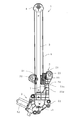
- FIG. 1 is a schematic side view showing an embodiment of a window regulator according to the present invention.
- a window regulator 1 according to the present invention is provided on a vehicle door or the like for opening and closing a window glass of a vehicle not shown in the figure.
- a carrier plate connected to the window glass of a vehicle. 2
- a guide rail 3 that guides the raising and lowering of the carrier plate 2
- a direction changing member 4 provided at one end of the guide rail 3
- a drive unit 5 provided at the other end of the guide rail 3
- a carrier plate 2 is connected to the drive unit 5 via the direction change member 4 and the other end is connected to the drive unit 5.
- the lower wire is connected to the carrier plate 2 and the other end is connected to the drive unit 5.
- Wire 7 is provided.
- the carrier plate 2 includes a guide rail fitting portion 21 that is fitted to the guide rail 3, and wire end coupling portions 22 and 23 to which one ends of the ascending wire 6 and the descending wire 7 are respectively coupled. And a stopper abutting portion 24 that abuts against a stopper 53c described later at the lower limit position of the carrier plate 2, and is slidable in the vertical direction along the guide rail 3.
- the carrier plate 2 can be integrally formed of, for example, a synthetic resin or the like, but may be formed by being fixed to each other separately by heat fusion or the like.
- the material of the carrier plate 2 is not particularly limited to a synthetic resin, and may be a metal or a combination of a metal and a synthetic resin.
- the guide rail fitting portion 21 and the stopper abutting portion 24 of the carrier plate 2 sandwich the wire end connecting portions 22 and 23 in the direction perpendicular to the ascending / descending direction of the carrier plate 2.
- the guide rail fitting portion 21 and the stopper contact portion 24 are provided so as to be positioned on both sides of the wire end connecting portions 22 and 23.
- the guide rail fitting portion 21 is formed in a claw shape so as to engage with a side edge extending in the longitudinal direction of the guide rail 3, but is not particularly limited to this form. Any material that can be slidably fitted may be used.
- the carrier plate 2 has a fixing hole 25 for fixing a window glass (not shown) with a screw or the like.
- the guide rail 3 has a cross section by bending both ends in the width direction of a thin metal plate such as a substantially rectangular galvanized steel plate having a predetermined length in the ascending / descending direction of the carrier plate 2 in the same direction. It is formed to be U-shaped.
- the direction changing member 4 is used to change the direction of the ascending wire 6 by winding the ascending wire 6.
- an arcuate guide groove for slidably guiding the ascending wire 6 is used. Is formed.
- the direction change member 4 is not limited to this, You may make it attach the pulley etc. which were provided rotatably to the upper end of the guide rail 3 directly or via a bracket.
- the drive unit 5 is attached to the lower end of the guide rail 3 and is disposed below the lower limit position of the carrier plate 2.
- the drive unit 5 includes a drum 51 that winds and sends the ascending wire 6 and the descending wire 7, a motor 52 that drives the drum 51, and a housing 53.
- the drum 51 is provided with an engaging portion for engaging the ends of the ascending wire 6 and the descending wire 7, and the ascending wire 6 and the descending wire 7 are provided on the outer peripheral surface.
- a spiral guide groove is formed to wind up the vicinity of the end portion.
- the drum 51 is connected to a motor 52 via a speed reducer (not shown) such as a worm gear speed reducer. By driving the motor 52, the winding wire 6 and the lowering wire 7 are wound and Delivery is performed.
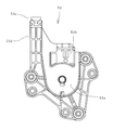
- the housing 53 includes a drum accommodating portion 53a that accommodates the drum 51, a guide rail connecting portion 53b that is connected to the lower end portion of the guide rail 3, and the carrier plate 2 that is lowered from the lower limit position. It has a stopper 53c for preventing this, and a stopper support portion 53d for supporting the stopper 53c.
- the material of the housing 53 is not particularly limited. For example, the weight of the housing 53 can be reduced by using a synthetic resin.
- the stopper 53c is for regulating the lower limit position of the carrier plate, and stops the carrier plate 2 at the lower limit position by contacting the carrier plate 2 when the window glass is lowered.
- the stopper 53c is in contact with the stopper contact portion 24 of the carrier plate 2.
- the stopper 53c may be in contact with any part of the carrier plate 2 as long as the carrier plate 2 can be stopped at the lower limit position.
- the material of the stopper 53c is not particularly limited. For example, an elastic member or the like can be used in order to suppress an impact sound at the time of contact with the stopper contact portion 24.
- the stopper support 53d is for supporting the stopper 53c, and is provided on the carrier plate 2 descending side with respect to the stopper 53c.
- a fitting portion for attaching the stopper 53c is formed at the distal end portion of the stopper support portion 53d, and the stopper 53c is fitted to the distal end of the stopper support portion 53d by fitting the lower end side of the stopper 53c into the fitting portion. Is provided.
- the stopper support portion 53d supports the stopper 53c from below and is provided integrally with the housing 53, so that the impact when the stopper 53c comes into contact with the stopper contact portion 24 of the carrier plate 2 is reliably ensured. Can be supported.
- the housing 53 is made of a synthetic resin or the like to reduce the weight, and accordingly, the strength can be further increased by increasing the cross-sectional area of the stopper support portion 53d.
- a stopper 53c made of an elastic member or the like is provided at the tip of the stopper support 53d.
- the tip of the stopper support 53d is brought into direct contact with the stopper contact portion 24 of the carrier plate 2. Thus, it may function as the stopper 53c.
- the drum 51 is rotated and driven by the motor 52 via the speed reducer so that the ascending wire 6 is wound around the drum 51 and the descending wire 7 is provided with the above-described configuration.
- the carrier plate 2 is raised by feeding it from the drum 51 to one end side. By raising the carrier plate 2 in this way, the window glass fixed to the carrier plate 2 is also raised. Further, by rotating the motor 52 in the reverse direction, the window wire can be lowered together with the carrier plate 2 by feeding the raising wire 6 from the drum 51 to one end side and winding the lowering wire 7 around the drum 51.
- the stopper 53c is provided in the housing 53 of the drive unit 5, it is not necessary to provide a bracket for fixing the stopper 53c, the number of parts can be reduced, and the stopper support Since the stopper 53c is supported from below by the portion 53d, it is possible to reliably support an impact when contacting the carrier plate 2.
- the guide rail fitting portion 21 and the stopper abutting portion 24 are arranged so as to sandwich the wire end connecting portions 22 and 23 therebetween in the direction perpendicular to the ascending / descending direction of the carrier plate 2. Therefore, when the stopper contact portion 24 comes into contact with the stopper 53c, the carrier plate 2 rotates around the guide rail fitting portion 21 due to the downward tension applied to the ascending wire 6 (the vehicle rear side). Can be prevented. Accordingly, the window glass can be prevented from rotating to the vehicle rear side when the window glass attached to the carrier plate 2 is in a fully opened state, that is, when the carrier plate 2 comes into contact with the stopper 53c. It doesn't look bad when fully open. Further, when the carrier plate 2 is raised from the fully opened state of the window glass, the generated contact glass and the glass run channel can be prevented by rotating the window glass toward the vehicle front side.
- the window regulator according to the present invention can be applied to a vehicle door or the like.
Landscapes
- Window Of Vehicle (AREA)
- Power-Operated Mechanisms For Wings (AREA)
Abstract
Description
2 キャリアプレート
21 ガイドレール嵌合部
22,23 ワイヤ端連結部
24 ストッパ当接部
3 ガイドレール
4 方向転換部材
5 駆動部
51 ドラム
52 モータ
53 ハウジング
53a ドラム収容部
53b ガイドレール接続部
53c ストッパ
53d ストッパ支持部
6 上昇用ワイヤ
7 下降用ワイヤ
72 固定部
Claims (3)
- 車両の窓ガラスに連結されるキャリアプレートと、
前記キャリアプレートの昇降を案内するガイドレールと、
前記ガイドレールの一端に設けられた方向転換部材と、
前記ガイドレールの他端に設けられた駆動部と、
前記キャリアプレートに一端が連結され、方向転換部材を経て他端が前記駆動部に連結された上昇用ワイヤと、
前記キャリアプレートに一端が連結され、他端が前記駆動部に連結された下降用ワイヤとを備えたウインドレギュレータにおいて、
前記駆動部は、前記上昇用ワイヤおよび前記下降用ワイヤを巻き取り、送り出すドラムと、前記ドラムを駆動するモータと、ハウジングとを有し、
前記ハウジングは、前記ドラムを収容するドラム収容部と、前記ガイドレールと接続されるガイドレール接続部と、前記キャリアプレートが下限位置に到達したときに前記キャリアプレートと当接し、前記キャリアプレートが更に下降するのを阻止するストッパと、前記ストッパに対し前記キャリアプレートの下降方向側へ設けられたストッパ支持部とを有することを特徴とするウインドレギュレータ。 - 前記ハウジングは合成樹脂製であることを特徴とする請求項1記載のウインドレギュレータ。
- 前記キャリアプレートは、前記ガイドレールと嵌合するガイドレール嵌合部と、前記上昇用ワイヤおよび前記下降用ワイヤの一端が連結されるワイヤ端連結部と、前記ストッパと当接するストッパ当接部とを有し、
前記ガイドレール嵌合部と前記ストッパ当接部は、前記キャリアプレートの昇降方向に対する垂直方向において、前記ワイヤ端連結部を間に挟むように配置されていることを特徴とする請求項1または2記載のウインドレギュレータ。
Priority Applications (3)
| Application Number | Priority Date | Filing Date | Title |
|---|---|---|---|
| CN201280052314.5A CN103890300B (zh) | 2011-10-25 | 2012-10-25 | 窗户调节器 |
| JP2013540832A JP6154326B2 (ja) | 2011-10-25 | 2012-10-25 | ウインドレギュレータ |
| US14/353,816 US9163448B2 (en) | 2011-10-25 | 2012-10-25 | Window regulator |
Applications Claiming Priority (2)
| Application Number | Priority Date | Filing Date | Title |
|---|---|---|---|
| JP2011234424 | 2011-10-25 | ||
| JP2011-234424 | 2011-10-25 |
Publications (1)
| Publication Number | Publication Date |
|---|---|
| WO2013062060A1 true WO2013062060A1 (ja) | 2013-05-02 |
Family
ID=48167886
Family Applications (1)
| Application Number | Title | Priority Date | Filing Date |
|---|---|---|---|
| PCT/JP2012/077646 Ceased WO2013062060A1 (ja) | 2011-10-25 | 2012-10-25 | ウインドレギュレータ |
Country Status (4)
| Country | Link |
|---|---|
| US (1) | US9163448B2 (ja) |
| JP (1) | JP6154326B2 (ja) |
| CN (1) | CN103890300B (ja) |
| WO (1) | WO2013062060A1 (ja) |
Cited By (7)
| Publication number | Priority date | Publication date | Assignee | Title |
|---|---|---|---|---|
| CN104612522A (zh) * | 2015-02-04 | 2015-05-13 | 陈学琴 | 齿带式弹簧缓冲齿轮升降器 |
| JP2016017312A (ja) * | 2014-07-08 | 2016-02-01 | シロキ工業株式会社 | ウインドレギュレータ |
| CN105960501A (zh) * | 2014-02-06 | 2016-09-21 | 株式会社城南制作所 | 车窗开闭调节器 |
| JP2019124103A (ja) * | 2018-01-19 | 2019-07-25 | 株式会社城南製作所 | ウインドレギュレータ |
| JP2019143401A (ja) * | 2018-02-22 | 2019-08-29 | 株式会社城南製作所 | ウインドレギュレータ |
| JP2019203272A (ja) * | 2018-05-21 | 2019-11-28 | 株式会社城南製作所 | ウインドレギュレータ |
| JP7620607B2 (ja) | 2022-12-26 | 2025-01-23 | 株式会社城南製作所 | ウインドレギュレータ及びストッパ部材の取付け方法 |
Families Citing this family (13)
| Publication number | Priority date | Publication date | Assignee | Title |
|---|---|---|---|---|
| JP6057078B2 (ja) * | 2013-08-07 | 2017-01-11 | 住友電装株式会社 | カールコードの配索構造 |
| JP5944882B2 (ja) * | 2013-12-17 | 2016-07-05 | シロキ工業株式会社 | ウインドレギュレータ及びウインドレギュレータの製造方法 |
| JP6344085B2 (ja) * | 2014-06-23 | 2018-06-20 | アイシン精機株式会社 | 昇降装置及びその昇降装置を備える車両用ドア |
| JP6345063B2 (ja) * | 2014-09-26 | 2018-06-20 | シロキ工業株式会社 | 車両用ウインドレギュレータ及び傾き抑制機構 |
| CN104746995B (zh) * | 2015-04-09 | 2018-01-30 | 上海世德子汽车零部件有限公司 | 一种汽车玻璃升降器 |
| JP6723826B2 (ja) * | 2016-05-24 | 2020-07-15 | シロキ工業株式会社 | ワイヤ式ウインドレギュレータ |
| JP6815304B2 (ja) * | 2017-10-31 | 2021-01-20 | 株式会社ハイレックスコーポレーション | 移動装置 |
| JP7029975B2 (ja) * | 2018-02-22 | 2022-03-04 | 株式会社城南製作所 | ウインドレギュレータ |
| JP6580738B1 (ja) * | 2018-03-26 | 2019-09-25 | 株式会社城南製作所 | ウインドレギュレータ |
| JP6898956B2 (ja) * | 2019-02-08 | 2021-07-07 | 株式会社城南製作所 | ウインドレギュレータ |
| WO2022094276A1 (en) * | 2020-10-30 | 2022-05-05 | Inteva Products, Llc | Window regulator with optimized motor configuration |
| JP7037692B1 (ja) * | 2021-08-10 | 2022-03-16 | 株式会社城南製作所 | ウインドレギュレータ |
| DE102022121891A1 (de) * | 2021-09-01 | 2023-03-02 | Magna Closures Inc. | Seilscheiben-verbindungshalter für fensterhebersystemfeld |
Citations (2)
| Publication number | Priority date | Publication date | Assignee | Title |
|---|---|---|---|---|
| JP2005113441A (ja) * | 2003-10-06 | 2005-04-28 | Shiroki Corp | ウインドレギュレータ |
| JP2008240515A (ja) * | 2001-03-19 | 2008-10-09 | Hi-Lex Corporation | ウインドレギュレータ |
Family Cites Families (14)
| Publication number | Priority date | Publication date | Assignee | Title |
|---|---|---|---|---|
| US4253277A (en) * | 1979-08-27 | 1981-03-03 | General Motors Corporation | Tape drive mechanism |
| JPH0345850Y2 (ja) * | 1984-10-25 | 1991-09-27 | ||
| JPH03209042A (ja) * | 1990-01-08 | 1991-09-12 | Koito Mfg Co Ltd | 昇降装置 |
| JP3456801B2 (ja) * | 1995-07-11 | 2003-10-14 | シロキ工業株式会社 | ウインドレギュレータのストッパ機構 |
| DE19857872C2 (de) * | 1997-12-16 | 2003-07-17 | Asmo Co Ltd | Angetriebener Fensterheber und Fensterhebersystem |
| US6061963A (en) * | 1999-05-05 | 2000-05-16 | General Motors Corporation | Window regulator mechanism |
| US7010884B2 (en) | 2003-10-06 | 2006-03-14 | Shiroki Kogyo Co., Ltd. | Window regulator |
| JP4193056B2 (ja) * | 2004-02-20 | 2008-12-10 | 三菱ふそうトラック・バス株式会社 | ドアウィンドレギュレータ構造 |
| CA2557149A1 (en) * | 2004-03-04 | 2005-09-15 | Intier Automotive Closures Inc. | Window regulator |
| DE102004017645A1 (de) * | 2004-04-02 | 2005-11-03 | Faurecia Innenraum Systeme Gmbh | Fensterheberanordnung und Verfahren zur Montage einer Fensterscheibe |
| JP4800030B2 (ja) * | 2005-12-27 | 2011-10-26 | 本田技研工業株式会社 | ウインドウガラスの昇降装置 |
| JP2009013669A (ja) * | 2007-07-04 | 2009-01-22 | Hi-Lex Corporation | ウインドレギュレータ |
| JP2010112016A (ja) * | 2008-11-04 | 2010-05-20 | Hi-Lex Corporation | 衝撃吸収体を備えたキャリアプレートまたはストッパ部材およびそれを用いたウインドレギュレータ装置 |
| JP5453008B2 (ja) * | 2009-07-27 | 2014-03-26 | 株式会社ハイレックスコーポレーション | ウインドレギュレータ装置 |
-
2012
- 2012-10-25 JP JP2013540832A patent/JP6154326B2/ja not_active Expired - Fee Related
- 2012-10-25 WO PCT/JP2012/077646 patent/WO2013062060A1/ja not_active Ceased
- 2012-10-25 CN CN201280052314.5A patent/CN103890300B/zh not_active Expired - Fee Related
- 2012-10-25 US US14/353,816 patent/US9163448B2/en active Active
Patent Citations (2)
| Publication number | Priority date | Publication date | Assignee | Title |
|---|---|---|---|---|
| JP2008240515A (ja) * | 2001-03-19 | 2008-10-09 | Hi-Lex Corporation | ウインドレギュレータ |
| JP2005113441A (ja) * | 2003-10-06 | 2005-04-28 | Shiroki Corp | ウインドレギュレータ |
Cited By (7)
| Publication number | Priority date | Publication date | Assignee | Title |
|---|---|---|---|---|
| CN105960501A (zh) * | 2014-02-06 | 2016-09-21 | 株式会社城南制作所 | 车窗开闭调节器 |
| JP2016017312A (ja) * | 2014-07-08 | 2016-02-01 | シロキ工業株式会社 | ウインドレギュレータ |
| CN104612522A (zh) * | 2015-02-04 | 2015-05-13 | 陈学琴 | 齿带式弹簧缓冲齿轮升降器 |
| JP2019124103A (ja) * | 2018-01-19 | 2019-07-25 | 株式会社城南製作所 | ウインドレギュレータ |
| JP2019143401A (ja) * | 2018-02-22 | 2019-08-29 | 株式会社城南製作所 | ウインドレギュレータ |
| JP2019203272A (ja) * | 2018-05-21 | 2019-11-28 | 株式会社城南製作所 | ウインドレギュレータ |
| JP7620607B2 (ja) | 2022-12-26 | 2025-01-23 | 株式会社城南製作所 | ウインドレギュレータ及びストッパ部材の取付け方法 |
Also Published As
| Publication number | Publication date |
|---|---|
| CN103890300B (zh) | 2016-08-24 |
| JP6154326B2 (ja) | 2017-06-28 |
| US9163448B2 (en) | 2015-10-20 |
| JPWO2013062060A1 (ja) | 2015-04-02 |
| US20140298725A1 (en) | 2014-10-09 |
| CN103890300A (zh) | 2014-06-25 |
Similar Documents
| Publication | Publication Date | Title |
|---|---|---|
| JP6154326B2 (ja) | ウインドレギュレータ | |
| JP6185386B2 (ja) | ウインドレギュレータ | |
| KR20040010611A (ko) | 만곡 글래스의 지지 구조 및 윈드 레귤레이터 | |
| WO2016171200A1 (ja) | ウインドレギュレータ | |
| JP6423319B2 (ja) | ウインドウレギュレータおよびその取付方法 | |
| JP4921221B2 (ja) | 給電装置 | |
| JP5925198B2 (ja) | ウインドレギュレータ | |
| US20130133265A1 (en) | Window regulator | |
| JP6739476B2 (ja) | ケーブル配索構造およびこれを用いた窓ガラス昇降装置 | |
| JP2020090888A (ja) | ウインドレギュレータ | |
| CN117627499A (zh) | 线缆安装构造及车窗开闭调节器 | |
| JP2015200149A (ja) | ウィンドレギュレータ装置 | |
| WO2012011593A1 (ja) | ウインドウレギュレータ | |
| KR101144075B1 (ko) | 차량용 윈도우 레귤레이터 | |
| JP3756424B2 (ja) | ワイヤ式ウィンドレギュレータ | |
| KR20110012553A (ko) | 차량용 윈도우 글라스 개폐장치 | |
| KR101991778B1 (ko) | 자동차용 윈도우 레귤레이터 | |
| JP6625833B2 (ja) | 対象物移動装置 | |
| CN105143583B (zh) | 车窗开闭调节器 | |
| JP2007239336A (ja) | 横型ブラインドのスラット駆動装置 | |
| JP5052266B2 (ja) | 給電構造 | |
| JP2020133109A (ja) | ガイドレスレギュレータ | |
| JP5064961B2 (ja) | ウインドレギュレータ装置 | |
| KR20090063820A (ko) | 차량의 윈도우 레귤레이터 장치 | |
| JP2013011139A (ja) | ウインドレギュレータ |
Legal Events
| Date | Code | Title | Description |
|---|---|---|---|
| 121 | Ep: the epo has been informed by wipo that ep was designated in this application |
Ref document number: 12843601 Country of ref document: EP Kind code of ref document: A1 |
|
| WWE | Wipo information: entry into national phase |
Ref document number: 14353816 Country of ref document: US |
|
| NENP | Non-entry into the national phase |
Ref country code: DE |
|
| ENP | Entry into the national phase |
Ref document number: 2013540832 Country of ref document: JP Kind code of ref document: A |
|
| 122 | Ep: pct application non-entry in european phase |
Ref document number: 12843601 Country of ref document: EP Kind code of ref document: A1 |