WO2012176808A1 - 全固体型リチウム二次電池及びその製造方法 - Google Patents
全固体型リチウム二次電池及びその製造方法 Download PDFInfo
- Publication number
- WO2012176808A1 WO2012176808A1 PCT/JP2012/065756 JP2012065756W WO2012176808A1 WO 2012176808 A1 WO2012176808 A1 WO 2012176808A1 JP 2012065756 W JP2012065756 W JP 2012065756W WO 2012176808 A1 WO2012176808 A1 WO 2012176808A1
- Authority
- WO
- WIPO (PCT)
- Prior art keywords
- positive electrode
- solid
- active material
- solid electrolyte
- electrode active
- Prior art date
- Legal status (The legal status is an assumption and is not a legal conclusion. Google has not performed a legal analysis and makes no representation as to the accuracy of the status listed.)
- Ceased
Links
Images





Classifications
-
- H—ELECTRICITY
- H01—ELECTRIC ELEMENTS
- H01M—PROCESSES OR MEANS, e.g. BATTERIES, FOR THE DIRECT CONVERSION OF CHEMICAL ENERGY INTO ELECTRICAL ENERGY
- H01M10/00—Secondary cells; Manufacture thereof
- H01M10/05—Accumulators with non-aqueous electrolyte
- H01M10/058—Construction or manufacture
- H01M10/0585—Construction or manufacture of accumulators having only flat construction elements, i.e. flat positive electrodes, flat negative electrodes and flat separators
-
- H—ELECTRICITY
- H01—ELECTRIC ELEMENTS
- H01B—CABLES; CONDUCTORS; INSULATORS; SELECTION OF MATERIALS FOR THEIR CONDUCTIVE, INSULATING OR DIELECTRIC PROPERTIES
- H01B1/00—Conductors or conductive bodies characterised by the conductive materials; Selection of materials as conductors
- H01B1/06—Conductors or conductive bodies characterised by the conductive materials; Selection of materials as conductors mainly consisting of other non-metallic substances
- H01B1/08—Conductors or conductive bodies characterised by the conductive materials; Selection of materials as conductors mainly consisting of other non-metallic substances oxides
-
- H—ELECTRICITY
- H01—ELECTRIC ELEMENTS
- H01M—PROCESSES OR MEANS, e.g. BATTERIES, FOR THE DIRECT CONVERSION OF CHEMICAL ENERGY INTO ELECTRICAL ENERGY
- H01M10/00—Secondary cells; Manufacture thereof
- H01M10/05—Accumulators with non-aqueous electrolyte
- H01M10/052—Li-accumulators
- H01M10/0525—Rocking-chair batteries, i.e. batteries with lithium insertion or intercalation in both electrodes; Lithium-ion batteries
-
- H—ELECTRICITY
- H01—ELECTRIC ELEMENTS
- H01M—PROCESSES OR MEANS, e.g. BATTERIES, FOR THE DIRECT CONVERSION OF CHEMICAL ENERGY INTO ELECTRICAL ENERGY
- H01M10/00—Secondary cells; Manufacture thereof
- H01M10/05—Accumulators with non-aqueous electrolyte
- H01M10/056—Accumulators with non-aqueous electrolyte characterised by the materials used as electrolytes, e.g. mixed inorganic/organic electrolytes
- H01M10/0561—Accumulators with non-aqueous electrolyte characterised by the materials used as electrolytes, e.g. mixed inorganic/organic electrolytes the electrolyte being constituted of inorganic materials only
- H01M10/0562—Solid materials
-
- H—ELECTRICITY
- H01—ELECTRIC ELEMENTS
- H01M—PROCESSES OR MEANS, e.g. BATTERIES, FOR THE DIRECT CONVERSION OF CHEMICAL ENERGY INTO ELECTRICAL ENERGY
- H01M2300/00—Electrolytes
- H01M2300/0017—Non-aqueous electrolytes
- H01M2300/0065—Solid electrolytes
- H01M2300/0068—Solid electrolytes inorganic
- H01M2300/0071—Oxides
-
- H—ELECTRICITY
- H01—ELECTRIC ELEMENTS
- H01M—PROCESSES OR MEANS, e.g. BATTERIES, FOR THE DIRECT CONVERSION OF CHEMICAL ENERGY INTO ELECTRICAL ENERGY
- H01M4/00—Electrodes
- H01M4/02—Electrodes composed of, or comprising, active material
- H01M4/04—Processes of manufacture in general
- H01M4/0471—Processes of manufacture in general involving thermal treatment, e.g. firing, sintering, backing particulate active material, thermal decomposition, pyrolysis
-
- H—ELECTRICITY
- H01—ELECTRIC ELEMENTS
- H01M—PROCESSES OR MEANS, e.g. BATTERIES, FOR THE DIRECT CONVERSION OF CHEMICAL ENERGY INTO ELECTRICAL ENERGY
- H01M4/00—Electrodes
- H01M4/02—Electrodes composed of, or comprising, active material
- H01M4/13—Electrodes for accumulators with non-aqueous electrolyte, e.g. for lithium-accumulators; Processes of manufacture thereof
- H01M4/131—Electrodes based on mixed oxides or hydroxides, or on mixtures of oxides or hydroxides, e.g. LiCoOx
-
- H—ELECTRICITY
- H01—ELECTRIC ELEMENTS
- H01M—PROCESSES OR MEANS, e.g. BATTERIES, FOR THE DIRECT CONVERSION OF CHEMICAL ENERGY INTO ELECTRICAL ENERGY
- H01M4/00—Electrodes
- H01M4/02—Electrodes composed of, or comprising, active material
- H01M4/13—Electrodes for accumulators with non-aqueous electrolyte, e.g. for lithium-accumulators; Processes of manufacture thereof
- H01M4/139—Processes of manufacture
- H01M4/1391—Processes of manufacture of electrodes based on mixed oxides or hydroxides, or on mixtures of oxides or hydroxides, e.g. LiCoOx
-
- Y—GENERAL TAGGING OF NEW TECHNOLOGICAL DEVELOPMENTS; GENERAL TAGGING OF CROSS-SECTIONAL TECHNOLOGIES SPANNING OVER SEVERAL SECTIONS OF THE IPC; TECHNICAL SUBJECTS COVERED BY FORMER USPC CROSS-REFERENCE ART COLLECTIONS [XRACs] AND DIGESTS
- Y02—TECHNOLOGIES OR APPLICATIONS FOR MITIGATION OR ADAPTATION AGAINST CLIMATE CHANGE
- Y02E—REDUCTION OF GREENHOUSE GAS [GHG] EMISSIONS, RELATED TO ENERGY GENERATION, TRANSMISSION OR DISTRIBUTION
- Y02E60/00—Enabling technologies; Technologies with a potential or indirect contribution to GHG emissions mitigation
- Y02E60/10—Energy storage using batteries
-
- Y—GENERAL TAGGING OF NEW TECHNOLOGICAL DEVELOPMENTS; GENERAL TAGGING OF CROSS-SECTIONAL TECHNOLOGIES SPANNING OVER SEVERAL SECTIONS OF THE IPC; TECHNICAL SUBJECTS COVERED BY FORMER USPC CROSS-REFERENCE ART COLLECTIONS [XRACs] AND DIGESTS
- Y02—TECHNOLOGIES OR APPLICATIONS FOR MITIGATION OR ADAPTATION AGAINST CLIMATE CHANGE
- Y02P—CLIMATE CHANGE MITIGATION TECHNOLOGIES IN THE PRODUCTION OR PROCESSING OF GOODS
- Y02P70/00—Climate change mitigation technologies in the production process for final industrial or consumer products
- Y02P70/50—Manufacturing or production processes characterised by the final manufactured product
Definitions
- the present invention relates to an all-solid-state lithium secondary battery and a method for manufacturing the same.
- an all-solid-state lithium secondary battery including a solid electrolyte and an active material has been proposed.
- the conductivity of lithium ions at the solid-solid interface between the solid electrolyte and the active material may be a problem.
- the adhesion of the joint surface may not be improved.
- the adhesion at the interface is increased by sintering at a high sintering temperature, the solid electrolyte or the active material is altered by the high temperature, or the interface resistance is increased between the solid electrolyte and the active material. A phase sometimes occurred. For this reason, a sufficient energy density may not be obtained because the conductivity of lithium ions between the solid electrolyte and the active material is inhibited.
- an active material containing a crystalline first material capable of releasing and occluding lithium ions is joined to a solid electrolyte containing a crystalline second material having lithium ion conductivity
- a sol-gel method is employed (see Non-patent Document 1), or a PLD method (pulse laser deposition method) that is a gas phase method is employed (see Patent Document 2).
- PLD method pulse laser deposition method
- the energy density is still insufficient, such as a discharge capacity of about 15 ⁇ Ahcm ⁇ 2 , and further improvements have been desired.
- the vapor phase method is employed as in Patent Document 2
- the lithium ion conductivity can be high between the solid electrolyte and the active material, but from the viewpoint of productivity, the vapor phase method can be used. It has been desired to increase the energy density by other methods.
- the present invention has been made in view of such problems, and has as its main object to provide an all-solid-state lithium secondary battery that can further increase the energy density and a method for manufacturing the same.
- the all solid-state lithium secondary battery of the present invention is A positive electrode having a positive electrode active material; A negative electrode having a negative electrode active material; A solid electrolyte interposed between the positive electrode and the negative electrode and conducting lithium ions; With On the positive electrode side surface of the solid electrolyte, (Li x (1- ⁇ ) , M x ⁇ / ⁇ ) ⁇ + (B 1-y , A y ) z + O 2- ⁇ ( In the formula, each of M and A is at least one element of C, Al, Si, Ga, Ge, In, and Sn, ⁇ satisfies 0 ⁇ ⁇ ⁇ 1, and ⁇ is the valence of M.
- the base material is the positive electrode active material and the solid electrolyte. It becomes a conduction path of lithium ions between them, and the utilization factor of the active material can be increased. Thereby, energy density can be raised.
- the “base material” means a material that fills the gap.
- Li 3 BO 3 which is one of (Li x (1- ⁇ ) , M x ⁇ / ⁇ ) ⁇ + (B 1 -y , A y ) z + O 2- ⁇ has a relatively low melting point of 650 ° C. Have Therefore, it is possible melting of Li 3 BO 3 at temperatures which the active material and the solid electrolyte is not or react with or Li 3 BO 3 alteration.
- the “flux” means a Li ion conductive material that fills the gap by solidifying at least a part thereof after being melted.
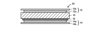
- FIG. 4 is an explanatory diagram showing an example of a structure of an all solid-state lithium secondary battery 20.
- FIG. 4 is an explanatory diagram showing an example of a structure of an all solid-state lithium secondary battery 20.
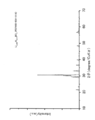
- FIG. 6 is an XRD pattern of powder used in the flux of Example 5.
- FIG. 2 is an XRD pattern of the composite used in Example 1.
- FIG. 7 is an XRD pattern of the composite of Reference Example 4.
- 2 is a cross-sectional SEM photograph of the composite used in Example 1.
- 10 is a cross-sectional SEM photograph of the composite used in Comparative Example 7.
- 2 is a cross-sectional SEM photograph (reflected electron image) of the composite used in Example 1.
- 3 shows constant voltage charge / discharge measurement results of batteries of Example 1, Comparative Example 7, and Comparative Example 8.
- An all solid-state lithium secondary battery of the present invention includes a positive electrode having a positive electrode active material, a negative electrode having a negative electrode active material, and a solid electrolyte interposed between the positive electrode and the negative electrode and conducting lithium ions, On the positive electrode side surface of the solid electrolyte, as a positive electrode active material and a base material, (Li x (1- ⁇ ) , M x ⁇ / ⁇ ) ⁇ + (B 1-y , A y ) z + O 2- ⁇ (where, M and A are each at least one element of C, Al, Si, Ga, Ge, In, and Sn, ⁇ satisfies 0 ⁇ ⁇ ⁇ 1, ⁇ is the valence of M, ⁇ is the average valence of (Li + x (1- ⁇ ) , M ⁇ ), y satisfies 0 ⁇ y ⁇ 1, z is the average valence of (B 1-y , A y ), x , ⁇
- the positive electrode has a positive electrode active material.
- a sulfide containing a transition metal element, an oxide containing lithium and a transition metal element, or the like can be used.
- transition metal sulfides such as TiS 2 , TiS 3 , MoS 3 , FeS 2 , Li (1-x) MnO 2 (0 ⁇ x ⁇ 1, etc., the same shall apply hereinafter), Li (1-x) Mn Lithium manganese composite oxide such as 2 O 4 , lithium cobalt composite oxide such as Li (1-x) CoO 2 , lithium nickel composite oxide such as Li (1-x) NiO 2 , lithium such as LiV 2 O 3 Vanadium composite oxides, transition metal oxides such as V 2 O 5, and the like can be used.
- lithium transition metal composite oxides such as LiCoO 2 , LiNiO 2 , LiMnO 2 , and LiV 2 O 3 are more preferable.
- an oxide-based positive electrode active material is unlikely to be plastically deformed, and in many cases, it is difficult to improve adhesion with a solid electrolyte by an external pressure. For this reason, the significance of application of the present invention is high in an all solid-state lithium secondary battery using an oxide-based positive electrode active material.
- the negative electrode has a negative electrode active material.
- the negative electrode active material include inorganic compounds such as lithium, lithium alloys and tin compounds, carbonaceous materials capable of inserting and extracting lithium ions, and conductive polymers.
- lithium alloys are preferable because they can reduce the interface resistance with the solid electrolyte.
- a lithium alloy containing at least one or more additive elements among Mg, Al, Si, In, Ag, and Sn is more preferable, and one containing Al or one containing In is more preferable.
- those containing In are preferable because even when the number of added atoms is smaller, the interface resistance between the solid electrolyte and the negative electrode can be further reduced.
- the negative electrode preferably contains an additive element in the range of 10% by mass to 30% by mass of the lithium alloy, and more preferably contains the additive element in a range of 15% by mass to 25% by mass. It is more preferable that the additive element contains mass%.
- the additive element contained is 10% by mass or more, the interface resistance can be further reduced, and when it is 30% by mass or less, the uniformity of the lithium alloy can be further improved. Note that details of the lithium alloy used for the negative electrode are described in Japanese Patent Application Laid-Open No. 2011-70939, and thus description thereof is omitted here.
- the positive electrode and the negative electrode may have a current collector.
- Current collectors include aluminum, titanium, stainless steel, nickel, iron, calcined carbon, conductive polymer, conductive glass, and aluminum, copper, etc. for the purpose of improving adhesion, conductivity, and oxidation resistance.
- a surface treated with carbon, nickel, titanium, silver or the like can be used. For these, the surface can be oxidized.
- Examples of the shape of the current collector include foil, film, sheet, net, punched or expanded, lath, porous, foam, and formed fiber group.
- a lithium ion conductive oxide is preferable.
- a garnet-type lithium ion conductive oxide is preferable.
- the garnet-type lithium ion conductive oxide has, for example, a basic composition Li x A 3 B 2 O 12 (where A and B are one or more elements, and x is a number that guarantees the overall charge balance). Can be represented.
- the garnet-type lithium ion conductive oxide has a basic composition Li 5 + x La 3 Zr x A 2 ⁇ x O 12 (where A is Sc, Ti, V, Y, Nb, Hf, Ta, It is more preferable that one or more elements selected from the group consisting of Al, Si, Ga and Ge, x is represented by 1.4 ⁇ x ⁇ 2).
- x is 1.4 ⁇ x ⁇ 2
- the chemical energy is also reduced.
- the conductivity is 2.5 ⁇ 10 ⁇ 4 Scm ⁇ 1 or more and the activation energy is 0.34 eV or less. Therefore, when this oxide is used for an all-solid-state lithium ion secondary battery, lithium ions are easily conducted, so that the output of the battery is improved. Further, since the activation energy is small, that is, the rate of change in conductivity with respect to temperature is small, the output of the battery is stabilized. Further, it is preferable that x satisfies 1.6 ⁇ x ⁇ 1.95 because conductivity is higher and activation energy is lower.
- x satisfies 1.65 ⁇ x ⁇ 1.9 because the conductivity is almost maximum and the activation energy is almost minimum.
- the details of the garnet-type lithium ion conductive oxide represented by the basic composition Li 5 + x La 3 Zr x A 2 ⁇ x O 12 are described in, for example, Japanese Patent Application Laid-Open No. 2010-202499. The description is omitted here.
- solid electrolyte various inorganic solid electrolytes, organic solid electrolytes, and the like can be used in addition to those described above.
- Well-known inorganic solid electrolytes include, for example, Li nitrides, halides, oxyacid salts, and the like. Among them, Li 4 SiO 4, Li 4 SiO 4 -LiI-LiOH, xLi 3 PO 4 - (1-x) Li 4 SiO 4, Li 2 SiS 3, Li 3 PO 4 -Li 2 S-SiS 2, sulfide Examples thereof include phosphorus compounds. These may be used alone or in combination.
- organic solid electrolyte examples include polyethylene oxide, polypropylene oxide, polyvinyl alcohol, polyvinylidene fluoride, polyphosphazene, polyethylene sulfide, polyhexafluoropropylene, and derivatives thereof. These may be used alone or in combination. Note that an oxide-based inorganic solid electrolyte hardly undergoes plastic deformation, and in many cases, it is more difficult to improve adhesion with a positive electrode active material by an external pressure. For this reason, the significance of application of the present invention is high in an all solid-state lithium secondary battery using an oxide-based inorganic solid electrolyte as a solid electrolyte.
- the mixed layer is in close contact with the positive electrode surface of the solid electrolyte.
- close contact means not two-dimensional contact but two-dimensional or three-dimensional contact (bonding). Whether or not it is “in close contact” can be confirmed, for example, by whether or not it is in point contact when a cross section is observed at a magnification of 5000 times using a scanning electron microscope.
- This mixed layer contains a positive electrode active material and (Li x (1- ⁇ ) , M x ⁇ / ⁇ ) ⁇ + (B 1 -y , A y ) z + O 2- ⁇ as a base material.
- each of M and A is at least one element of C, Al, Si, Ga, Ge, In, and Sn, ⁇ satisfies 0 ⁇ ⁇ ⁇ 1, and ⁇ is the valence of M.
- ⁇ is the average valence of (Li + x (1- ⁇ ) , M ⁇ ), y satisfies 0 ⁇ y ⁇ 1, and z is the average valence of (B 1-y , A y )
- the base material may be Li 3 BO 3 containing neither M nor A, or Li is substituted with M but B is not substituted with A (Li x (1- ⁇ ) , M x ⁇ / ⁇ ).
- ⁇ + B 3+ O 2 ⁇ ⁇ may be used, or Li + x (B 1 ⁇ y , A y ) z + O 2 ⁇ ⁇ in which B is substituted with A but Li is not substituted with M.
- Li may be substituted with M and B may be substituted with A.
- M and A may be the same or different elements.
- M is preferably an element having a 4-coordination
- A is a tricoordinate. It is preferable that the element takes a position.
- Li 3 BO 3 Li is tetracoordinated and B is tricoordinated. Therefore, an element having a tetracoordinate easily replaces Li, and an element having a tricoordinate easily replaces B. .
- M preferably has an ionic radius of 4-coordination close to that of Li + (4-coordinate), and A has an ion radius of B 3+ (3-coordinate) when tricoordinated. It is preferable to be close to the radius. This is because element substitution is considered possible if the ionic radius is close.
- the ionic radii of C, Al, Si, Ga, Ge, In, and Sn are shown. The ionic radii when the tetracoordinate is taken are: C 4+ : 0.15 ⁇ , Al 3+ : 0.39 ⁇ , Si 4+ : 0.40 ⁇ , Ga 3+ : 0.47 ⁇ , Ge 4+ : 0.39 , In 3+ : 0.62 ⁇ and Sn 4+ : 0.55 ⁇ .
- the ion radius of Li + (4-coordinate) is 0.59 ⁇ .
- the ionic radii when taking the three-coordination are as follows: C 4+ : 0.15 ⁇ , Al 3+ : 0.39 ⁇ , Si 4+ : 0.40 3 , Ga 3+ : 0.47 ⁇ , Ge 4+ : 0 .39 ⁇ , In 3+ : 0.62 ⁇ , Sn 4+ : 0.55 ⁇ .
- the ion radius of B + (tricoordinate) is 0.15 ⁇ .
- M preferably has a higher valence than Li, and A is It is preferable that the valence is larger than B. This is because when Li is substituted with M having a higher valence than Li, defects are introduced into Li to compensate for the charge of the composition, and the conduction path of lithium ions increases. Also, when B is substituted with A having a higher valence than B, defects are introduced to compensate for the charge of the composition. In this case, the lithium ion conduction path is increased by introducing defects due to the lack of Li having a higher vapor pressure than B.
- M and A may be at least one of C, Al, Si, Ga, Ge, In, and Sn. At least one of M and A is preferably Al. This is because the introduction of M and A can increase the lithium ion conductivity, but when at least one of M and A is Al, the lithium ion conductivity can be further increased. This is because an effect of improving output characteristics can be expected by increasing the conductivity of lithium ions. Note that (Li x (1- ⁇ ) , M x ⁇ / ⁇ ) ⁇ + (B 1-y , A y ) z + O 2- ⁇ does not have to have a stoichiometric composition and is partially missing.
- This mixed layer preferably has a structure in which particles of the positive electrode active material are dispersed in the base material. Lithium ion conductivity between the positive electrode active material particles or between the positive electrode active material particles and the solid electrolyte (Li x (1- ⁇ ) , M x ⁇ / ⁇ ) ⁇ + (B 1-y , This is because the presence of A y ) z + O 2 ⁇ ⁇ facilitates securing a lithium ion conduction path between the positive electrode active materials or between the positive electrode active material and the solid electrolyte.
- the base material is more preferably a material (melted product) that is solidified after being melted including the positive electrode active material particles. This is because if the base material is once solidified after being in a liquid phase, the base material enters between the positive electrode active material and the solid electrolyte, and it is easier to secure a lithium ion conduction path.
- the positive electrode active material and the solid electrolyte do not change in quality or produce a reaction product.
- the peak of the reaction product between the positive electrode active material and the base material and the peak of the reaction product between the solid electrolyte and the base material are not confirmed in the XRD measurement using CuK ⁇ rays.
- the peak of the reaction product of a positive electrode active material and a solid electrolyte is not confirmed. This is because it is considered that the generation of a deteriorated layer or a third phase that reduces the lithium ion conductivity is suppressed.
- the shape of the all solid-state lithium secondary battery of the present invention is not particularly limited, and examples thereof include a coin type, a button type, a sheet type, a laminated type, a cylindrical type, a flat type, and a rectangular type. Further, a plurality of such lithium secondary batteries connected in series may be applied to a large battery used for an electric vehicle or the like.
- the structure of the all solid-state lithium secondary battery of the present invention is not particularly limited, and examples thereof include the structures shown in FIG. 1 and FIG. 1 includes a solid electrolyte layer 10, a positive electrode 12 formed on one side of the solid electrolyte layer 10, and a negative electrode 14 formed on the other side of the solid electrolyte layer 10.
- the positive electrode 12 includes a mixed layer 12a (a layer containing a positive electrode active material) in contact with the solid electrolyte layer 10 and a current collector 12b in contact with the mixed layer 12a
- the negative electrode 14 is a negative electrode in contact with the solid electrolyte layer 10.
- the all-solid-state lithium secondary battery 20 of FIG. 2 includes a solid electrolyte layer 10 made of a garnet-type oxide, a positive electrode 12 formed on one side of the solid electrolyte layer 10, and the other side of the solid electrolyte layer 10. And the negative electrode 14 formed through the polymer electrolyte layer 16.
- the positive electrode 12 includes a mixed layer 12a and a current collector 12b
- the negative electrode 14 includes a negative electrode active material layer 14a and a current collector 14b.
- the manufacturing method of the all-solid-state lithium secondary battery of this invention includes: (1) (Lix (1- ⁇ ) , Mx ⁇ / ⁇ ) ⁇ + ( B1 -y , Ay ) z + as a positive electrode active material and a flux.
- the raw material layer containing a positive electrode active material and a flux is formed in the solid electrolyte surface.
- the flux is represented by (Lix (1- ⁇ ) , Mx ⁇ / ⁇ ) ⁇ + ( B1 -y , Ay ) z + O2 - ⁇ .
- each of M and A is at least one element of C, Al, Si, Ga, Ge, In, and Sn, ⁇ satisfies 0 ⁇ ⁇ ⁇ 1, and ⁇ is the valence of M.
- ⁇ is the average valence of (Li + x (1- ⁇ ) , M ⁇ ), y satisfies 0 ⁇ y ⁇ 1, and z is the average valence of (B 1-y , A y )
- ⁇ and y preferably satisfy 0 ⁇ ⁇ ⁇ 0.5 and 0 ⁇ y ⁇ 0.5, and more preferably satisfy 0 ⁇ ⁇ ⁇ 0.3 and 0 ⁇ y ⁇ 0.3.
- the flux may be Li 3 BO 3 containing neither M nor A, or Li is substituted with M but B is not substituted with A (Li x (1- ⁇ ) , M x ⁇ / ⁇ ) ⁇ + B 3+ O 2- ⁇ may be used as the, B is is substituted with A Li is not substituted with the M Li + x (B 1- y, A y) may be z + O 2- ⁇ Li may be substituted with M and B may be substituted with A.
- M and A may be the same element or different elements.
- M is preferably an element having a 4-coordination
- A is a tricoordinate. It is preferable that the element takes a position.
- Li 3 BO 3 Li is tetracoordinated and B is tricoordinated. Therefore, an element having a tetracoordinate easily replaces Li, and an element having a tricoordinate easily replaces B. .
- M preferably has an ionic radius of 4-coordination close to that of Li + (4-coordinate), and A has an ion radius of B 3+ (3-coordinate) when tricoordinated.
- M preferably has a higher valence than Li, and A is It is preferable that the valence is larger than B. This is because when Li is substituted with M having a higher valence than Li, defects are introduced into Li to compensate for the charge of the composition, and the conduction path of lithium ions increases. Also, when B is substituted with A having a higher valence than B, defects are introduced to compensate for the charge of the composition.
- the lithium ion conduction path is increased by introducing defects due to the lack of Li having a higher vapor pressure than B.
- M and A may be at least one of C, Al, Si, Ga, Ge, In, and Sn. At least one of M and A is preferably Al. This is because the lithium ion conductivity can be increased by introducing M and A, but when at least one of M and A is Al, the lithium ion conductivity can be further increased. This is because an effect of improving output characteristics can be expected by increasing the conductivity of lithium ions.
- the interface where the positive electrode active material and the solid electrolyte are in direct contact can be further increased by melting and solidifying the positive electrode active material.
- the flux may have a function as a sintering aid. This is because the conductivity of lithium ions can be further increased by increasing the sinterability between the positive electrode active materials or between the positive electrode active material and the solid electrolyte.
- a mixture of the positive electrode active material and the flux may be formed as a layer, a layer of the positive electrode active material may be formed, and then a flux layer may be formed.
- the positive electrode active material layer may be formed after the layer is formed.
- the positive electrode active material layer and the flux layer may be alternately formed.
- a paste obtained by adding a binder or the like to the positive electrode active material or flux (hereinafter also referred to as a raw material paste) may be used.
- a binder cellulose binders such as ethyl cellulose, methyl cellulose, and carboxymethyl cellulose, and various binders such as butyral resins and acrylic resins can be used.
- organic solvents such as a terpionel, acetone, and toluene, as a solvent.
- the raw material paste can be obtained by mixing a positive electrode active material, a flux, a binder, a solvent, and the like using a normal paste manufacturing method using a triroll mill, a pot mill, or the like.
- a method of forming a raw material paste layer on the surface of the solid electrolyte for example, a known liquid supply method such as a dispenser, dipping, spray, etc., a doctor blade method, a printing method such as screen printing, metal mask printing, etc. Can be used.
- screen printing is preferable because the thickness and pattern can be controlled with high accuracy.
- metal mask printing it is easy to form a raw material paste with a thickness, and thus shape control becomes easy.
- the solid electrolyte formed with the raw material layer is heated above the melting point of the flux, the temperature at which the positive electrode active material and the flux produce a compound, and the temperature at which the solid electrolyte and the flux produce a compound. Heat at a temperature below the lower one.
- a flux will be in a liquid phase state and can improve adhesiveness with a solid electrolyte.
- the positive electrode active material and the flux are heated at a temperature lower than the temperature at which the compound generates the compound and the solid electrolyte and the flux generate the compound, the positive electrode active material and the solid electrolyte and the flux No reaction product is produced.
- the heating temperature is preferably lower than the temperature at which the positive electrode active material and the solid electrolyte react.
- the temperature is preferably such that the positive electrode active material and the solid electrolyte are not altered.
- the temperature at which the positive electrode active material or the solid electrolyte is not altered may be determined based on the treatment temperature during synthesis of the positive electrode active material or the solid electrolyte.
- the heating temperature is more than 600 ° C and preferably 900 ° C or less, more preferably 650 ° C or more and 800 ° C or less, and further preferably 700 ° C or more and 750 ° C or less.
- the atmosphere during heating is not particularly limited, but is preferably an air atmosphere or an oxidizing atmosphere. In such an atmosphere, the desorption of oxygen from the Li 3 BO 3 structure is suppressed, and when the positive electrode active material or the solid electrolyte is an oxide, the desorption of oxygen from the positive electrode active material or the solid electrolyte is performed. Is suppressed. Therefore, the flux, the positive electrode active material, and the solid electrolyte are hardly deteriorated, and reaction products are hardly generated.
- Example 1 (1) Preparation of solid electrolyte Li 2 CO 3 , La (OH) 3 , ZrO 2 , and Nb 2 O 5 are used as starting materials, and Li 6.75 La 3 Zr 1.75 Nb 0.25 O 12 (hereinafter also referred to as LLZONb) This starting material was weighed so as to have a stoichiometric ratio of the basic composition, and mixed and pulverized in ethanol in a planetary ball mill (300 rpm / zirconia ball) for 4 hours. Next, after the mixed powder of the starting material (inorganic material) was separated from zirconia balls and ethanol, calcination was performed in an Al 2 O 3 crucible at 950 ° C.
- LLZONb Li 6.75 La 3 Zr 1.75 Nb 0.25 O 12
- Li 2 CO 3 is added to the calcined powder so that the Li amount is 5 at% with respect to the Li amount in the inorganic material for the purpose of making up for the loss of Li in the main firing.
- it was pulverized and mixed in a planetary ball mill (300 rpm / zirconia ball) for 6 hours in ethanol.
- the obtained powder was again calcined under atmospheric pressure at 950 ° C. for 5 hours.
- the obtained powder was molded to a diameter of 13 mm and a thickness of 2 mm and subjected to isostatic pressing (CIP) between cold water, and then the sintering temperature was set to 1150 ° C. for 36 hours under atmospheric conditions.
- CIP isostatic pressing
- LiCoO 2 powder was synthesized by heat-treating the powder in an alumina crucible at 850 ° C. for 20 hours under atmospheric conditions. 20 g of the synthesized LiCoO 2 powder and 12 g of a binder (manufactured by Nisshin Kasei Co., Ltd., EC vehicle (mixture of ethyl cellulose and terpione)) were mixed to prepare a positive electrode active material paste.
- a binder manufactured by Nisshin Kasei Co., Ltd., EC vehicle (mixture of ethyl cellulose and terpione)
- This starting material is prepared using Li 2 CO 3 and B 2 O 3 as starting materials so that the molar ratio of Li 2 CO 3 and B 2 O 3 is 1: 1 (total amount is about 50 g).
- Li 3 BO 3 became a liquid phase, and the raw material layer became a LiCoO 2 —Li 3 BO 3 mixed layer.
- Au as a current collector was sputter coated on the mixed layer surface of the obtained composite.
- LiIn (20 mass% In) as a negative electrode was pressed on the surface opposite to the side where the positive electrode (mixed layer) was baked in a glove box in an Ar atmosphere to obtain a negative electrode.
- This battery was placed in a sealed container, and the insulated lead wire was taken out of the container to obtain a collector electrode.
- XRD measurement was performed about the produced composite_body
- complex. XRD measurement was performed using Rigaku's TTR. Radiation source: CuK ⁇ line, 1 step: 0.02 deg / sec, 2 ⁇ 10 to 80 deg. Measurement was carried out in the range of.
- Example 2 A battery of Example 2 was fabricated through the same process as Example 1 except that baking was performed at 700 ° C. Further, a battery of Example 3 was fabricated through the same steps as in Example 1 except that baking was performed at 800 ° C. Moreover, the battery of Example 4 was produced through the process similar to Example 1 except having baked at 900 degreeC.
- Example 5 A battery of Example 5 was manufactured through the same steps as Example 1 except that the following “(3 ′) Preparation of flux paste” was performed instead of “(3) Preparation of flux paste”.
- the zirconia beads and the raw material mixed powder were separated by a sieve, and the powder was put in an alumina crucible at 600 ° C.
- Range XRD measurement was performed in the. .XRD pattern showing the XRD pattern of the powder 3, since consistent with PDF ⁇ 00-054-1116, the powder is Li 2.358 Al 0.214 BO was confirmed to be 3.
- Comparative Example 1 A battery of Comparative Example 1 was fabricated through the same steps as in Example 1 except that baking was performed at 600 ° C.
- Comparative Example 7 A battery of Comparative Example 7 was fabricated through the same steps as in Example 1 except that baking was performed at 850 ° C. without using flux.
- Comparative Example 8 A battery in which a positive electrode active material (LiCoO 2 ) was adhered to the solid electrolyte produced by the method described in Example 1 by the PLD method was produced as Comparative Example 8.
- a positive electrode active material LiCoO 2
- the positive electrode active material layer had a diameter of 6 mm and a thickness of 4 ⁇ m. Thereafter, the pellet provided with the positive electrode active material layer was annealed in an electric furnace at 500 ° C.
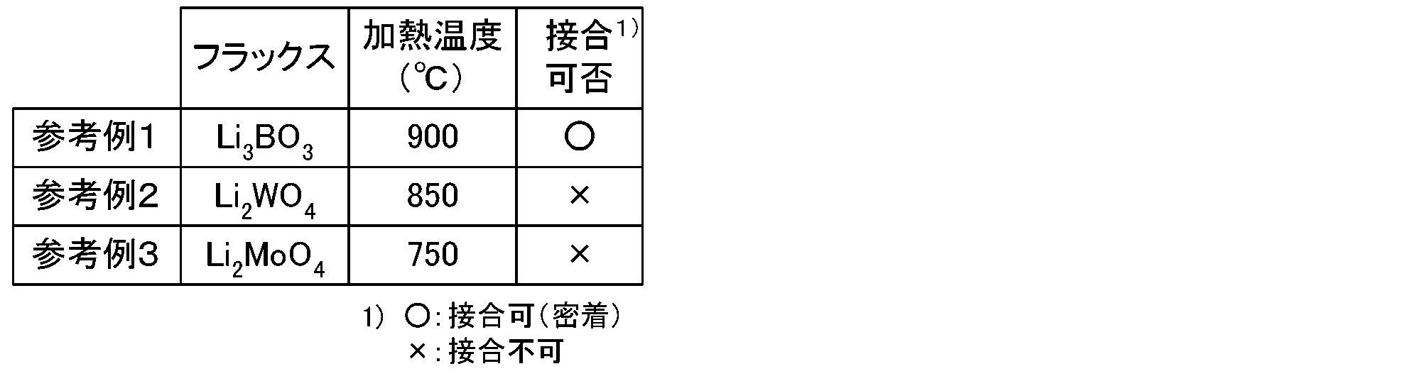
- Reference Example 1 A composite of Reference Example 1 was produced through the same steps as Example 1 except that LLZONb was used instead of LiCoO 2 and baking was performed at 900 ° C. Further, a composite of Reference Example 2 was obtained through the same process as Reference Example 1 except that Li 2 MoO 4 was used as a flux and baking was performed at 750 ° C. Further, a composite of Reference Example 3 was obtained through the same steps as Reference Example 1 except that Li 2 WO 4 was used as a flux and baking was performed at 850 ° C.
- FIG. 4 shows the XRD spectrum of the composite of Example 1.
- LiCoO 2 is a sample prepared (positive electrode active material), Li 3 BO 3 (base material), a peak of LLZONb (solid electrolyte) was observed. From the above, it was found that Li 3 BO 3 , LiCoO 2 , and LLZONb did not cause chemical reaction, third phase formation, or alteration.
- FIG. 5 shows the XRD pattern of the composite of Reference Example 4.
- peaks of Li 3 BO 3 and Al 2 O 3 used as the substrate were confirmed. From this, it was found that even when Al 2 O 3 is used as the substrate, Li 3 BO 3 and Al 2 O 3 do not cause chemical reaction, formation of a third phase, or alteration.
- the peaks of LiCoO 2 and LLZONb were large and it was difficult to distinguish the peak of Li 3 BO 3 , but the composite of Reference Example 4 produced under the same firing conditions as in Example 1 was used. The peak of Li 3 BO 3 was clearly confirmed. From this, it was speculated that Li 3 BO 3 was produced in the composite of Example 1 as in Reference Example 4.
- FIG. 6 the cross-sectional SEM photograph (secondary electron image) of the composite_body
- a cross section of the composite of Comparative Example 7 in which a LiCoO 2 paste without flux was applied on LLZONb pellets and baked under the same conditions as in Example 1 was observed by SEM.
- FIG. 7 the cross-sectional SEM photograph of the composite_body
- FIG. 8 the cross-sectional SEM photograph (reflected electron image) of the composite_body
- FIG. 8A is a low-magnification photograph
- FIG. 8B is a high-magnification photograph.
- a heavy element is white and a light element is black.
- LLZONb containing the heavy elements La and Zr is the whitest
- LiCoO 2 containing only the heavy element Co is white next to LLZONb
- Li 3 BO 3 consisting only of the light element is the blackest. From this, it was found that in the composite of Example 1, LiCoO 2 that is the particles of the positive electrode active material is dispersed in Li 3 BO 3 that is the base material.
- FIG. 9 the constant voltage charging / discharging result of the battery of Example 1 and the batteries of Comparative Examples 7 and 8 is shown.
- the battery of Example 1 having the base material was found to have the same battery characteristics as the battery of Comparative Example 8 produced by the PLD method.
- the charge / discharge characteristics were very small. The reason was presumed as follows. LiCoO 2 layer having no base material is an aggregate of particles, and LiCoO 2 and LLZONb, contact of LiCoO 2 between the point contact. For this reason, it is considered that the lithium ion conduction path is not sufficiently formed and sufficient charge / discharge characteristics cannot be obtained.
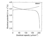
- FIG. 10 and 11 show measurement results of constant current charge / discharge of the battery of Example 1.
- FIG. 10 The capacity per unit area of the positive electrode of the battery of Example 1 was about 212 ⁇ Ahcm ⁇ 2 (FIG. 10). Further, the capacity per unit weight of the positive electrode active material was 103 mAhg ⁇ 1 (FIG. 11). Since the theoretical capacity of LiCoO 2 is 136 mAhg ⁇ 1 (assuming that 0.5 mol of Li is desorbed from the CoO 2 layer at 4.2 V (vs. Li + / Li)), in Example 1, the active material The utilization of was found to be about 75%.
- FIG. 12 is a graph showing the relationship between the heat treatment temperature and the battery capacity.
- FIG. 12 is created based on the experimental results of Examples 1 to 3 and Comparative Examples 3 and 5. From FIG. 12, it was found that the heat treatment temperature exceeded 600 ° C. and was preferably 900 ° C. or less, more preferably 650 ° C. or more and 800 ° C. or less, and more preferably 700 ° C. or more and 750 ° C. or less. The reason why the battery capacity was low at 650 ° C. or lower was presumed as follows. In order for the battery of the present invention to operate, it is important that the flux is once in a liquid phase.
- the melting point of the flux (Li 3 BO 3 ) used this time is about 650 ° C.
- the lithium ion conduction path between LiCoO 2 particles and between LiCoO 2 and LLZONb is not sufficiently liquid phase below the melting point. It was inferred that was not formed.
- the temperature is 900 ° C.
- a chemical reaction between LiCoO 2 and LLZONb occurs. Therefore, it is considered that a third phase having high resistance was formed by decomposition of LiCoO 2 or movement of lithium ions at the interface. It was speculated that the battery capacity was reduced by this.
- Table 1 shows the experimental results of Examples 1 to 5 and Comparative Examples 1 to 8 (bonding availability, discharge capacity), Table 2 shows the experimental results of Reference Examples 1 to 3 (bonding availability), and Table 3 shows Reference Example 5
- the experimental results (lithium ion conductivity) are shown. From this result, it was found that the flux preferably contains boron (B). Moreover, even if it contains boron, charge / discharge could not be performed in Comparative Example 2 using B 2 O 3 and Comparative Example 3 using Li 2 B 4 O 7 . When the composite of Comparative Example 2 was confirmed by XRD, formation of a Li—B—O-based compound was confirmed.
- Example 4 where the heating temperature was 900 ° C., LiCoBO 3 was generated at the bonding interface. From this, it was inferred that the charge / discharge characteristics deteriorate due to the reaction between the flux and the positive electrode active material, and it was found that the heating temperature is preferably set to a temperature that does not react with the positive electrode active material or the solid electrolyte.
- LLZONb was used instead of LiCoO 2 , but no heterogeneous phase was confirmed even when the composite was measured by XRD.
- Li 3 BO 3 has lithium ion conductivity. For this reason, it was guessed that the reduction
- Example 1 using Li 3 BO 3 as the flux and Example 5 using Li 2.358 Al 0.214 BO 3 both showed substantially the same results in terms of whether or not bonding was possible and the discharge capacity. From this, it was found that even when a part of Li or B was substituted with Al, a good bonding state could be obtained and the discharge capacity could be increased.
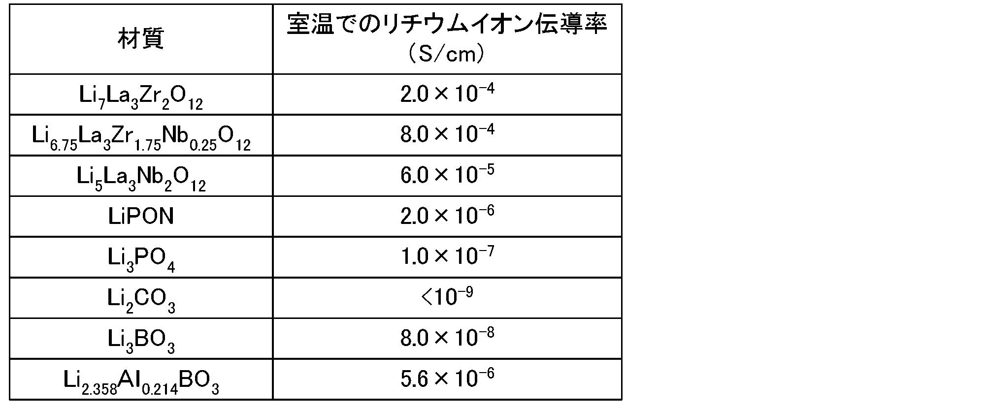
- the lithium ion conductivity of Li 2.358 Al 0.214 BO 3 was higher than the lithium ion conductivity of Li 3 BO 3 . From this, it was found that the lithium ion conductivity can be increased when a part of Li or B is substituted with Al.
- the higher the lithium ion conductivity of the material constituting the positive electrode, the negative electrode and the solid electrolyte the better the output characteristics. From this, it was inferred that the output characteristics can be improved by substituting a part of Li and B with Al.
- the coordination number, ionic radius, valence, etc. are close to those of Al, so it is assumed that the same effect as Al can be obtained. It was.
- the present invention can be used for an all solid state lithium ion secondary battery.
Landscapes
- Chemical & Material Sciences (AREA)
- Engineering & Computer Science (AREA)
- General Chemical & Material Sciences (AREA)
- Manufacturing & Machinery (AREA)
- Chemical Kinetics & Catalysis (AREA)
- Electrochemistry (AREA)
- Materials Engineering (AREA)
- Physics & Mathematics (AREA)
- Condensed Matter Physics & Semiconductors (AREA)
- General Physics & Mathematics (AREA)
- Inorganic Chemistry (AREA)
- Secondary Cells (AREA)
- Battery Electrode And Active Subsutance (AREA)
Abstract
Description
正極活物質を有する正極と、
負極活物質を有する負極と、
前記正極と前記負極との間に介在し、リチウムイオンを伝導する固体電解質と、
を備え、
前記固体電解質の前記正極側表面には、前記正極活物質と母材として(Lix(1-α),Mxα/β)γ+(B1-y,Ay)z+O2- δ(式中、M及びAは、各々、C,Al,Si,Ga,Ge,In,Snのうち少なくとも1種以上の元素であり、αは0≦α<1を満たし、βはMの価数であり、γは(Li+ x(1-α),Mα)の平均価数であり、yは0≦y<1を満たし、zは(B1-y,Ay)の平均価数であり、x,α,β,γ,z,δは(x(1-α)+xα/β)γ+z=2δの関係式を満たす。)とを含む混合層が密着している、ものである。
正極活物質とフラックスとして(Lix(1-α),Mxα/β)γ+(B1-y,Ay)z+O2- δ(式中、M及びAは、各々、C,Al,Si,Ga,Ge,In,Snのうち少なくとも1種以上の元素であり、αは0≦α<1を満たし、βはMの価数であり、γは(Li+ x(1-α),Mα)の平均価数であり、yは0≦y<1を満たし、zは(B1-y,Ay)の平均価数であり、x,α,β,γ,z,δは(x(1-α)+xα/β)γ+z=2δの関係式を満たす。)とを含む原料層を、固体電解質表面に形成する形成工程と、
前記原料層を形成した固体電解質を、前記フラックスの融点以上、かつ、前記正極活物質と前記フラックスとが化合物を生成する温度及び前記固体電解質と前記フラックスとが化合物を生成する温度のうちの低い温度以下の温度で加熱する加熱工程と、
を含むものである。
形成工程では、正極活物質とフラックスとを含む原料層を、固体電解質表面に形成する。なお、正極活物質の詳細については、上述したものと同様であるため、ここでは記載を省略する。フラックスは、(Lix(1-α),Mxα/β)γ+(B1-y,Ay)z+O2- δで表されるものである。式中、M及びAは、各々、C,Al,Si,Ga,Ge,In,Snのうち少なくとも1種以上の元素であり、αは0≦α<1を満たし、βはMの価数であり、γは(Li+ x(1-α),Mα)の平均価数であり、yは0≦y<1を満たし、zは(B1-y,Ay)の平均価数であり、x,α,β,γ,z,δは(x(1-α)+xα/β)γ+z=2δの関係式を満たす。α及びyは、0≦α≦0.5,0≦y≦0.5を満たすことが好ましく、0≦α≦0.3,0≦y≦0.3を満たすことがより好ましい。フラックスは、MもAも含まないLi3BO3としてもよいし、LiがMで置換されているがBがAで置換されていない(Lix(1-α),Mxα/β)γ+B3+O2- δとしてもよいし、BがAで置換されているがLiがMで置換されていないLi+ x(B1-y,Ay)z+O2- δとしてもよいし、LiがMで置換されかつBがAで置換されたものとしてもよい。LiがMで置換されかつBがAで置換されたものである場合、MとAとは、同種の元素でもよいし異種の元素でもよい。(Lix(1-α),Mxα/β)γ+(B1-y,Ay)z+O2- δにおいて、Mは4配位をとる元素であることが好ましく、Aは3配位をとる元素であることが好ましい。Li3BO3では、Liは4配位、Bは3配位をとるため、4配位をとる元素はLiを置換しやすいし、3配位をとる元素はBを置換しやすいからである。また、Mは4配位のときのイオン半径がLi+(4配位)のイオン半径と近いことが好ましく、Aは3配位のときのイオン半径がB3+(3配位)のイオン半径と近いことが好ましい。イオン半径が近ければ、元素の置換が可能と考えられるからである。(Lix(1-α),Mxα/β)γ+(B1-y,Ay)z+O2- δにおいて、MはLiよりも価数が大きいものであることが好ましく、AはBよりも価数が大きいものであることが好ましい。Liよりも価数が大きいMでLiを置換した場合、組成の電荷を補償するため、Liに欠陥が導入され、リチウムイオンの伝導経路が増加するからである。また、Bよりも価数が大きいAでBを置換した場合も、組成の電荷を補償するため、欠陥が導入される。この場合、Bよりも蒸気圧の高いLiが欠損することで欠陥が導入されることにより、リチウムイオンの伝導経路が増加する。このような、配位数、イオン半径、価数などの観点から、M及びAは、各々、C,Al,Si,Ga,Ge,In,Snのうち少なくとも1種以上であればよいが、M及びAの少なくとも一方はAlであることが好ましい。MやAの導入によってリチウムイオン伝導度を高めることができるが、MやAの少なくとも一方がAlである場合には、リチウムイオンの伝導度をより高めることができるからである。そして、リチウムイオンの伝導度を高めることにより、出力特性を高める効果などが期待できるからである。なお、(Lix(1-α),Mxα/β)γ+(B1-y,Ay)z+O2- δは、化学量論組成でなくてもよく、一部が欠損していてもよいし、過剰でもよいし、元素の一部が他の元素に置換されていてもよい。このフラックスは、後の加熱工程において、少なくとも自らが融解する。その後、少なくとも一部が固化して母材となり、正極活物質とともに、混合層として固体電解質の正極側表面に密着する。このフラックスは、正極活物質や固体電解質の融点を下げ、融解しやすくする機能を有するものでもよい。このようなものであれば、フラックスの融解及び凝固に際し、正極活物質をも融解及び凝固させることによって、正極活物質と固体電解質とが直接に接する界面をより増加させることができるからである。また、フラックスは、焼結助剤としての機能を有するものでもよい。このようなものであれば、正極活物質どうしや正極活物質と固体電解質との焼結性を高めることによって、リチウムイオンの伝導性をより高めることができるからである。
加熱工程では、原料層を形成した固体電解質を、フラックスの融点以上、かつ、正極活物質とフラックスとが化合物を生成する温度及び固体電解質とフラックスとが化合物を生成する温度のうちの低い温度以下の温度で加熱する。このように、フラックスの融点以上の温度で加熱するため、フラックスが液相状態となり、固体電解質との密着性を高めることができる。また、正極活物質とフラックスとが化合物を生成する温度及び固体電解質とフラックスとが化合物を生成する温度のうちの低い温度以下の温度で加熱するため、正極活物質や固体電解質と、フラックスとの反応生成物が生じない。これにより、リチウムイオンの伝導度を低下させるような第三相の生成を抑制できる。さらに、加熱温度は、正極活物質と固体電解質が反応する温度より低い温度であることが好ましい。また、正極活物質や固体電解質の変質が生じない温度であることが好ましい。これにより、リチウムイオンの伝導度を低下させるような第三相や変質層の生成をより抑制できる。なお、正極活物質や固体電解質の変質が生じない温度は、正極活物質や固体電解質の合成時の処理温度に基づいて定めてもよい。合成時の処理温度よりも低温であれば変質が生じにくいと考えられるからである。加熱温度は、具体的には、600℃を超え900℃以下が好ましく、650℃以上800℃以下がより好ましく、700℃以上750℃以下がさらに好ましい。加熱時の雰囲気は特に限定されないが、大気雰囲気や酸化性雰囲気であることが好ましい。このような雰囲気では、Li3BO3の構造から酸素の脱離が抑制され、また、正極活物質や固体電解質が酸化物である場合には、正極活物質や固体電解質からの酸素の脱離が抑制される。このため、フラックスや正極活物質、固体電解質の変質が生じにくく、また、反応生成物が生じにくいからである。
(1)固体電解質の作製
Li2CO3、La(OH)3、ZrO2、および、Nb2O5を出発原料とし、Li6.75La3Zr1.75Nb0.25O12(以下ではLLZONbとも称する)の基本組成の化学量論比になるようにこの出発原料を秤量し、エタノール中にて遊星ボールミル(300rpm/ジルコニアボール)で4時間、混合・粉砕を行った。次に、出発原料(無機材料)の混合粉末をジルコニアボールとエタノールから分離したのち、Al2O3るつぼ中にて、950℃、10時間の条件で大気雰囲気で仮焼を行った。その後、本焼成でのLiの欠損をも補う目的で、仮焼した粉末に対してLi2CO3を無機材料中のLi量に対してLi量が5at%となるように添加し、仮焼した粉末の粉砕と混合の目的で、エタノール中にて遊星ボールミル(300rpm/ジルコニアボール)で6時間粉砕混合した。得られた粉末を再び大気圧下、950℃、5時間の条件下で仮焼した。続いて、得られた粉末を直径13mm、厚さ2mmに成形し冷水間等方加圧(CIP)を施したのち、成形焼成温度を1150℃とし、36時間、大気中の条件下で本焼成を行い、ペレット状の固体電解質を得た。CIPは、溶媒を水とし、27℃、200MPaの条件で行った。
Li2CO3およびCoOを出発原料とし、Li2CO3とCoOとのモル比が1:2(総量約50g)となるようにこの出発原料を秤量し、エタノール(100ml)中にて遊星ボールミル(300rpm/ジルコニアポッド(500cc)/ジルコニアビーズ(3mmφ、500g))で1時間、混合・粉砕を行った。その後、設定温度80℃の乾燥機中にて脱溶媒を行った後、篩にて、ジルコニアビーズと原料混合粉末を分離した。その粉末をアルミナるつぼ中にて850℃、20時間、大気中条件下で熱処理することでLiCoO2粉末を合成した。合成したLiCoO2粉末20gとバインダー(日新化成製、ECビヒクル(エチルセルロースとターピオネールの混合物))12gとを混合し、正極活物質ペーストを作製した。
Li2CO3およびB2O3を出発原料とし、Li2CO3とB2O3とのモル比が1:1(総量約50g)となるようにこの出発原料を秤量し、エタノール(100ml)中にて遊星ボールミル(300rpm/ジルコニアポッド(500cc)/ジルコニアビーズ(3mmφ、500g)で1時間、混合・粉砕を行った。その後、設定温度80℃の乾燥機中にて脱溶媒を行った後、篩にて、ジルコニアビーズと原料混合粉末を分離した。その粉末をアルミナるつぼ中にて600℃、12時間、大気中条件下で熱処理することでLi3BO3粉末を合成した。合成したLi3BO3粉末20gとバインダー(日新化成製、ECビヒクル)14gとを混合し、フラックスペーストを作製した。
作製したペレット状の固体電解質の表面をサンドペーパー(♯6000)で研磨した。この研磨面にスクリーン印刷法にて、フラックスペーストを塗布した。このときスクリーンのサイズは10mmφとした。そして、150℃に設定した乾燥機中にて約10分間かけて脱溶媒を行った。なお、脱溶媒後のフラックスペーストの重量は約1.8mgであった。このLi3BO3の上に、10mmφのスクリーンを利用して正極活物質ペーストを塗布し、150℃に設定した乾燥機中にて約10分間かけて脱溶媒を行った。なお、脱溶媒後の正極活物質ペーストの重量は約1.8mgであった。得られたものを、大気中にて750℃にて1時間加熱して焼き付けを行い複合体を作製した。なお、この焼き付けの際、Li3BO3は液相化し、原料層は、LiCoO2-Li3BO3混合層となった。そして、得られた複合体の混合層表面に、集電体としてのAuをスパッターコートした。その後、Ar雰囲気のグローブボックス中で、正極(混合層)を焼き付けたのと反対側の面に負極としてのLiIn(20質量%In)を押しつけて負極とした。この電池を密閉容器中にいれ、絶縁したリード線を容器外に取り出すことで集電極とした。
作製した複合体について、XRD測定を行った。XRD測定は、Rigaku社製TTRにて、線源:CuKα線、1step:0.02deg/sec、2θ=10~80deg.の範囲で測定を実施した。
作製した複合体についてSEM観察を行った。SEM観察は、走査電子顕微鏡(HITACHI製、S-3400N)を用いて行った。
25℃に設定した恒温槽中にて、以下の実験を行った。
(A)定電圧充放電
以下の条件で、定電圧充放電を行った。
レート:0.1mV/sec. 走査電位:2.5~4.2V(vs.Li+/Li)
(B)定電流充放電
以下の条件で、定電流充放電を行った。
電流値:2.5μcm-2 走査電位:2.5~4.2V(vs.Li+/Li)
700℃で焼き付けを行った以外は実施例1と同様の工程を経て実施例2の電池を作製した。また、800℃で焼き付けを行った以外は実施例1と同様の工程を経て実施例3の電池を作製した。また、900℃で焼き付けを行った以外は実施例1と同様の工程を経て実施例4の電池を作製した。
上記「(3)フラックスペーストの作製」に代えて、以下の「(3’)フラックスペーストの作製」を行った以外は、実施例1と同様の工程を経て実施例5の電池を作製した。
Li2CO3 、B2O3及びγAl2O3を出発原料とし、Li2CO3とB2O3とγAl2O3とのモル比が2.358:1:0.107(総量約50g)となるようにこの出発原料を秤量し、エタノール(100ml)中にて遊星ボールミル(300rpm/ジルコニアポッド(500cc)/ジルコニアビーズ(3mmφ、500g)で1時間、混合・粉砕を行った。その後、設定温度80℃の乾燥機中にて脱溶媒を行った後、篩にて、ジルコニアビーズと原料混合粉末を分離した。その粉末をアルミナるつぼ中にて600℃、12時間、大気中条件下で熱処理することで粉末を合成した。得られた粉末について、Rigaku社製TTRにて、線源:CuKα線、1step:0.02deg/sec、2θ=10~70deg.の範囲でXRD測定を実施した。図3にこの粉末のXRDパターンを示す。XRDパターンは、PDF♯00-054-1116と一致したことから、この粉末は、Li2.358Al0.214BO3であることが確認された。合成したLi2.358Al0.214BO3粉末20gとバインダー(日新化成製、ECビヒクル)14gとを混合し、フラックスペーストを作製した。なお、Alは4配位をとりやすいことから、実施例5では、Alは主にLiを置換していると考えられる。
600℃で焼き付けを行った以外は実施例1と同様の工程を経て比較例1の電池を作製した。
フラックスとしてB2O3を用い、900℃で焼き付けを行った以外は、実施例1と同様の工程を経て比較例2の電池を作製した。また、フラックスとしてLi2B4O7を用い、900℃で焼き付けを行った以外は、実施例1と同様の工程を経て比較例3の電池を作製した。
フラックスとしてBi2O3を用い、900℃で焼き付けを行った以外は、実施例1と同様の工程を経て比較例4の電池を作製した。フラックスとしてWO3を用い、900℃で焼き付けを行った以外は、実施例1と同様の工程を経て比較例5の電池を作製した。また、フラックスとしてLi2WO4を用い、950℃で焼き付けを行った以外は、実施例1と同様の工程を経て比較例6の電池を作製した。
フラックスを用いず、850℃で焼き付けを行った以外は、実施例1と同様の工程を経て比較例7の電池を作製した。
実施例1に記載の方法で作製した固体電解質に、正極活物質(LiCoO2)をPLD法で密着させた電池を作製し、比較例8とした。PLD法では、Nd-YAGレーザー(λ=266nm,E=~1Jcm-2pls-1)を用い、製膜時のチャンバー酸素圧PO2を10Paとし、温度を常温とした。正極活物質層は直径6mm,厚さ4μmであった。その後、正極活物質層を備えたペレットを電気炉中にて500℃、1時間の条件(大気雰囲気)でアニール処理したのち、正極活物質層の上にAuペーストを塗布し、400℃、30分の条件で正極集電体であるAu金属板を焼きつけた。正極活物質層とAu金属板とAuペーストとが正極に相当する。その後、この正極の付いたペレットをグローブボックス(Ar雰囲気)中に導入後、正極の付いていない面に負極LiIn(In20質量%)を押し付けることで比較例8の電池を作製した。
LiCoO2の代わりにLLZONbを用い、900℃で焼き付けを行った以外は実施例1と同様の工程を経て、参考例1の複合体を作製した。また、フラックスにLi2MoO4を用い、750℃で焼き付けを行った以外は参考例1と同様の工程を経て、参考例2の複合体を得た。また、フラックスにLi2WO4を用い、850℃で焼き付けを行った以外は参考例1と同様の工程を経て、参考例3の複合体を得た。
Al2O3基板を用意し、表面をサンドペーパー(♯6000)で研磨した。この研磨面にスクリーン印刷法にて、実施例1の「(3)フラックスペーストの作製」で得られたフラックスペーストを塗布した。このときのスクリーンのサイズは10mmφとした。そして、150℃に設定した乾燥機中にて約10分間かけて脱溶媒を行った。なお、脱溶媒後のフラックスペーストの重量は約1.8mgであった。得られたものを、大気中700℃にて1時間加熱して焼き付けを行い、複合体を得た。この複合体について、XRD測定を行った。XRD測定は、Rigaku社製TTRにて、線源:CuKα線、1step:0.02deg/sec、2θ=10~90deg.の範囲で測定を実施した。
Li7La3Zr2O12,Li6.75Zr1.75Nb0.25O12,Li5La3Nb2O12,LiPON,Li3PO4,Li2CO3,Li3BO3、Li2.358Al0.214BO3のペレット状の試料を作製し、それぞれ、室温でのリチウムイオン伝導率を測定した。リチウムイオン伝導率の測定は、作製した試料にAuをイオンコーターで形成することで電極とし、交流インピーダンス測定によりリチウムイオン伝導率を測定した。
図4に、実施例1の複合体のXRDスペクトルを示す。図4より、作製した試料にはLiCoO2(正極活物質)と、Li3BO3(母材)、LLZONb(固体電解質)のピークが観察された。以上のことから、Li3BO3や、LiCoO2、LLZONbは、化学反応や第三相の形成、変質などを生じていないことがわかった。

Claims (11)
- 正極活物質を有する正極と、
負極活物質を有する負極と、
前記正極と前記負極との間に介在し、リチウムイオンを伝導する固体電解質と、
を備え、
前記固体電解質の前記正極側表面には、前記正極活物質と母材として(Lix(1-α),Mxα/β)γ+(B1-y,Ay)z+O2- δ(式中、M及びAは、各々、C,Al,Si,Ga,Ge,In,Snのうち少なくとも1種以上の元素であり、αは0≦α<1を満たし、βはMの価数であり、γは(Li+ x(1-α),Mα)の平均価数であり、yは0≦y<1を満たし、zは(B1-y,Ay)の平均価数であり、x,α,β,γ,z,δは(x(1-α)+xα/β)γ+z=2δの関係式を満たす。)とを含む混合層が密着している、
全固体型リチウム二次電池。 - 前記混合層は、前記正極活物質の粒子が前記母材中に分散している構造である、請求項1に記載の全固体型リチウム二次電池。
- 前記母材は、前記正極活物質の粒子を含んで融解したのちに固化したものである、請求項1又は2に記載の全固体型リチウム二次電池。
- 前記正極活物質及び前記固体電解質は、CuKα線を用いたXRD測定において、前記正極活物質と前記母材との反応生成物のピーク及び、前記固体電解質と前記母材との反応生成物のピークが確認されない、請求項1~3のいずれか1項に記載の全固体型リチウム二次電池。
- 前記固体電解質は、基本式Li5+xLa3ZrxA2-xO12(式中、Aは、Sc,Ti,V,Y,Nb,Hf,Ta,Al,Si,GaおよびGeからなる群より選ばれた1種類以上の元素,xは1.4≦x<2)で表されるガーネット型酸化物である、請求項1~4のいずれか1項に記載の全固体型リチウム二次電池。
- 前記母材は、(Lix(1-α),Mxα/β)γ+B3+O2- δである、請求項1~5のいずれか1項に記載の全固体型リチウム二次電池。
- 前記母材は、Li+ x(B1-y,Ay)z+O2- δである、請求項1~5のいずれか1項に記載の全固体型リチウム二次電池。
- 前記母材は、Li3BO3である、請求項1~7のいずれか1項に記載の全固体型リチウム二次電池。
- 正極活物質とフラックスとして(Lix(1-α),M1xα/β)γ+(B1-y,M2y)z+O2- δ(式中、M1及びM2は、各々、C,Al,Si,Ga,Ge,In,Snのうち少なくとも1種以上の元素であり、αは0≦α<1を満たし、βはM1の価数であり、γは(Li+ x(1-α),M1α)の平均価数であり、yは0≦y<1を満たし、zは(B1-y,Ay)の平均価数であり、x,α,β,γ,z,δは(x(1-α)+xα/β)γ+z=2δの関係式を満たす。)とを含む原料層を、固体電解質表面に形成する形成工程と、
前記原料層を形成した固体電解質を、前記フラックスの融点以上、かつ、前記正極活物質と前記フラックスとが化合物を生成する温度及び前記固体電解質と前記フラックスとが化合物を生成する温度のうちの低い温度以下の温度で加熱する加熱工程と、
を含む、全固体型リチウム二次電池の製造方法。 - 前記加熱工程では、650℃以上800℃以下の温度で加熱する、請求項9に記載の全固体型リチウム二次電池の製造方法。
- 前記固体電解質は、基本式Li5+xLa3ZrxA2-xO12(式中、Aは、Sc,Ti,V,Y,Nb,Hf,Ta,Al,Si,GaおよびGeからなる群より選ばれた1種類以上の元素,xは1.4≦x<2)で表されるガーネット型酸化物である、請求項9又は10に記載の全固体型リチウム二次電池の製造方法。
Priority Applications (2)
| Application Number | Priority Date | Filing Date | Title |
|---|---|---|---|
| US14/127,825 US10530015B2 (en) | 2011-06-20 | 2012-06-20 | All-solid-state lithium secondary battery and method for producing the same |
| JP2013521601A JP5854045B2 (ja) | 2011-06-20 | 2012-06-20 | 全固体型リチウム二次電池及びその製造方法 |
Applications Claiming Priority (2)
| Application Number | Priority Date | Filing Date | Title |
|---|---|---|---|
| JP2011136509 | 2011-06-20 | ||
| JP2011-136509 | 2011-06-20 |
Publications (1)
| Publication Number | Publication Date |
|---|---|
| WO2012176808A1 true WO2012176808A1 (ja) | 2012-12-27 |
Family
ID=47422640
Family Applications (1)
| Application Number | Title | Priority Date | Filing Date |
|---|---|---|---|
| PCT/JP2012/065756 Ceased WO2012176808A1 (ja) | 2011-06-20 | 2012-06-20 | 全固体型リチウム二次電池及びその製造方法 |
Country Status (3)
| Country | Link |
|---|---|
| US (1) | US10530015B2 (ja) |
| JP (1) | JP5854045B2 (ja) |
| WO (1) | WO2012176808A1 (ja) |
Cited By (15)
| Publication number | Priority date | Publication date | Assignee | Title |
|---|---|---|---|---|
| JP2013184848A (ja) * | 2012-03-07 | 2013-09-19 | Osaka Prefecture Univ | リチウムイオン伝導性酸化物及びその製造方法 |
| JP2016015213A (ja) * | 2014-07-01 | 2016-01-28 | 株式会社豊田中央研究所 | 複合積層体の製造方法、複合積層体及びリチウム電池 |
| JP2016100218A (ja) * | 2014-11-21 | 2016-05-30 | 株式会社豊田中央研究所 | 複合体、電池、複合体の製造方法及びイオン伝導性固体の製造方法 |
| JP2016532244A (ja) * | 2013-09-27 | 2016-10-13 | フォルシュングスツェントルム・ユーリッヒ・ゲゼルシャフト・ミット・ベシュレンクテル・ハフツング | 固体電池の電気化学セルの製造方法 |
| JP2016225089A (ja) * | 2015-05-28 | 2016-12-28 | 株式会社豊田中央研究所 | 電極、電極の製造方法及び電池 |
| JP2017004672A (ja) * | 2015-06-08 | 2017-01-05 | セイコーエプソン株式会社 | 電極複合体、電極複合体の製造方法およびリチウム電池 |
| JP2017142885A (ja) * | 2016-02-08 | 2017-08-17 | セイコーエプソン株式会社 | 電極複合体の製造方法、リチウムイオン電池の製造方法、電極複合体、リチウムイオン電池 |
| US10026990B2 (en) | 2014-10-16 | 2018-07-17 | Corning Incorporated | Lithium-ion conductive garnet and method of making membranes thereof |
| JP2018125150A (ja) * | 2017-01-31 | 2018-08-09 | 日立造船株式会社 | 全固体電池およびその製造方法 |
| US10431806B2 (en) * | 2013-01-07 | 2019-10-01 | Quantumscape Corporation | Thin film lithium conducting powder material deposition from flux |
| JP2020017535A (ja) * | 2019-10-21 | 2020-01-30 | セイコーエプソン株式会社 | 電極複合体の製造方法 |
| JP2020074289A (ja) * | 2019-10-21 | 2020-05-14 | セイコーエプソン株式会社 | 電極複合体の製造方法 |
| US10818964B2 (en) | 2015-12-07 | 2020-10-27 | Toyota Jidosha Kabushiki Kaisha | Composite solid electrolyte |
| US11296355B2 (en) | 2017-04-17 | 2022-04-05 | Corning Incorporated | Lithium-garnet solid electrolyte composite, tape articles, and methods thereof |
| US12249685B2 (en) | 2019-11-28 | 2025-03-11 | Samsung Electro-Mechanics Co., Ltd. | All solid battery |
Families Citing this family (35)
| Publication number | Priority date | Publication date | Assignee | Title |
|---|---|---|---|---|
| US8986895B2 (en) | 2009-02-04 | 2015-03-24 | Kabushiki Kaisha Toyota Chuo Kenkyusho | Garnet-type lithium ion-conducting oxide and all-solid-state lithium ion secondary battery containing the same |
| WO2012176808A1 (ja) | 2011-06-20 | 2012-12-27 | 株式会社豊田中央研究所 | 全固体型リチウム二次電池及びその製造方法 |
| JP6028694B2 (ja) | 2013-08-23 | 2016-11-16 | 株式会社豊田中央研究所 | ガーネット型イオン伝導性酸化物の製造方法及び複合体の製造方法 |
| US10403931B2 (en) | 2013-10-07 | 2019-09-03 | Quantumscape Corporation | Garnet materials for Li secondary batteries and methods of making and using garnet materials |
| US20160308244A1 (en) * | 2015-04-14 | 2016-10-20 | Corning Incorporated | Lithium-oxide garnet batch composition and solid electrolyte membrane thereof |
| KR20240059640A (ko) | 2015-04-16 | 2024-05-07 | 퀀텀스케이프 배터리, 인코포레이티드 | 고체 전해질 제조를 위한 리튬 함유 가넷 세터 플레이트 |
| JP2016219130A (ja) * | 2015-05-15 | 2016-12-22 | セイコーエプソン株式会社 | 固体電解質電池、電極複合体、複合固体電解質および固体電解質電池の製造方法 |
| JP2018528916A (ja) | 2015-07-21 | 2018-10-04 | クアンタムスケイプ コーポレイション | グリーンガーネット薄膜を流延及び焼結するプロセス及び材料 |
| US10770757B2 (en) * | 2015-10-23 | 2020-09-08 | Seiko Epson Corporation | Manufacturing method of electrode assembly |
| US9966630B2 (en) | 2016-01-27 | 2018-05-08 | Quantumscape Corporation | Annealed garnet electrolyte separators |
| US20170331092A1 (en) | 2016-05-13 | 2017-11-16 | Quantumscape Corporation | Solid electrolyte separator bonding agent |
| EP3252024B1 (en) | 2016-05-27 | 2019-12-18 | Toyota Jidosha Kabushiki Kaisha | Oxide electrolyte sintered body and method for producing the same |
| US11158880B2 (en) | 2016-08-05 | 2021-10-26 | Quantumscape Battery, Inc. | Translucent and transparent separators |
| US11916200B2 (en) | 2016-10-21 | 2024-02-27 | Quantumscape Battery, Inc. | Lithium-stuffed garnet electrolytes with a reduced surface defect density and methods of making and using the same |
| JP6565950B2 (ja) | 2017-02-02 | 2019-08-28 | トヨタ自動車株式会社 | ガーネット型酸化物固体電解質の製造方法 |
| JP7065323B2 (ja) * | 2017-02-09 | 2022-05-12 | パナソニックIpマネジメント株式会社 | 全固体電池およびその製造方法 |
| DE102017111970A1 (de) | 2017-05-31 | 2018-12-06 | Epcos Ag | Leiterplatte mit Stromversorgung, elektrisches Bauelement mit Leiterplatte und Verfahren zur Herstellung einer Leiterplatte |
| US10347937B2 (en) | 2017-06-23 | 2019-07-09 | Quantumscape Corporation | Lithium-stuffed garnet electrolytes with secondary phase inclusions |
| WO2018236394A1 (en) | 2017-06-23 | 2018-12-27 | Quantumscape Corporation | LITHIUM-FILLED GRENATE ELECTROLYTES WITH SECONDARY PHASE INCLUSIONS |
| US10431820B2 (en) | 2017-07-10 | 2019-10-01 | Uchicago Argonne, Llc | High valent lithiated surface structures for lithium ion battery electrode materials |
| JP2019046721A (ja) | 2017-09-05 | 2019-03-22 | トヨタ自動車株式会社 | スラリー、固体電解質層の製造方法、及び、全固体電池の製造方法 |
| JP6962094B2 (ja) * | 2017-09-21 | 2021-11-05 | トヨタ自動車株式会社 | ガーネット型イオン伝導性酸化物、及び、酸化物電解質焼結体の製造方法 |
| WO2019090360A1 (en) | 2017-11-06 | 2019-05-09 | Quantumscape Corporation | Lithium-stuffed garnet thin films and pellets having an oxyfluorinated and/or fluorinated surface and methods of making and using the thin films and pellets |
| JP7017079B2 (ja) | 2017-12-28 | 2022-02-08 | トヨタ自動車株式会社 | 電極の製造方法、電極、及び、電極-電解質層接合体 |
| JP6988473B2 (ja) | 2017-12-28 | 2022-01-05 | トヨタ自動車株式会社 | 電池用セパレータ、及び、リチウム電池、並びに、これらの製造方法 |
| JP6988472B2 (ja) | 2017-12-28 | 2022-01-05 | トヨタ自動車株式会社 | 電池 |
| US12046712B2 (en) | 2018-06-06 | 2024-07-23 | Quantumscape Battery, Inc. | Solid-state battery |
| DE102018218262A1 (de) * | 2018-10-25 | 2020-04-30 | Robert Bosch Gmbh | Feststoffelektrolytmaterial mit verbesserter chemischer Stabilität |
| EP3933978B1 (en) * | 2019-02-28 | 2026-02-04 | Panasonic Intellectual Property Management Co., Ltd. | Positive electrode material, and battery |
| US12469876B2 (en) | 2020-01-15 | 2025-11-11 | Quantumscape Battery, Inc. | High green density ceramics for battery |
| KR102824196B1 (ko) * | 2020-03-24 | 2025-06-24 | 주식회사 엘지에너지솔루션 | 전고체전지용 리튬금속 단위셀의 제조방법 및 그에 의해 제조된 단위셀 |
| FR3110028B1 (fr) | 2020-05-07 | 2022-10-14 | Accumulateurs Fixes | Particule peu dense revêtue et son utilisation comme électrolyte dans des batteries |
| FR3110285B1 (fr) * | 2020-05-18 | 2022-07-29 | Renault Sas | Electrode positive poreuse multicouche à sécurité et durée de vie élevées |
| KR102937842B1 (ko) | 2021-02-16 | 2026-03-10 | 삼성에스디아이 주식회사 | 전고체 이차전지 및 그 제조방법 |
| EP4309228B1 (en) | 2021-09-27 | 2025-01-22 | QuantumScape Battery, Inc. | Electrochemical stack and method of assembly thereof |
Citations (9)
| Publication number | Priority date | Publication date | Assignee | Title |
|---|---|---|---|---|
| JPH11283664A (ja) * | 1998-03-27 | 1999-10-15 | Kyocera Corp | 固体電解質電池 |
| JP2004235155A (ja) * | 2003-01-30 | 2004-08-19 | Samsung Electronics Co Ltd | 固体電解質、その製造方法及びそれを採用した電池 |
| JP2008251225A (ja) * | 2007-03-29 | 2008-10-16 | Tdk Corp | 全固体リチウムイオン二次電池及びその製造方法 |
| JP2009193940A (ja) * | 2008-02-18 | 2009-08-27 | Toyota Motor Corp | 電極体及びその製造方法、並びに、リチウムイオン二次電池 |
| JP2009238739A (ja) * | 2008-03-07 | 2009-10-15 | Tokyo Metropolitan Univ | 固体電解質構造体の製造方法、全固体電池の製造方法、固体電解質構造体及び全固体電池 |
| JP2010102929A (ja) * | 2008-10-23 | 2010-05-06 | Toyota Central R&D Labs Inc | リチウム含有ガーネット型酸化物、リチウム二次電池及び固体電解質の製造方法 |
| JP2010140725A (ja) * | 2008-12-10 | 2010-06-24 | Namics Corp | リチウムイオン二次電池、及び、その製造方法 |
| JP2010202499A (ja) * | 2009-02-04 | 2010-09-16 | Toyota Central R&D Labs Inc | ガーネット型リチウムイオン伝導性酸化物 |
| JP2011129474A (ja) * | 2009-12-21 | 2011-06-30 | Namics Corp | リチウムイオン二次電池 |
Family Cites Families (17)
| Publication number | Priority date | Publication date | Assignee | Title |
|---|---|---|---|---|
| JPH0644971A (ja) | 1992-07-22 | 1994-02-18 | Matsushita Electric Ind Co Ltd | 非水電解質リチウム二次電池 |
| JP4497585B2 (ja) | 1999-07-27 | 2010-07-07 | 株式会社豊田中央研究所 | リチウム二次電池用正極ペースト組成物およびリチウム二次電池用正極 |
| JP4069066B2 (ja) | 2003-12-24 | 2008-03-26 | 三井金属鉱業株式会社 | リチウム−マンガン系複合酸化物の製造方法 |
| JP5165843B2 (ja) | 2004-12-13 | 2013-03-21 | パナソニック株式会社 | 活物質層と固体電解質層とを含む積層体およびこれを用いた全固体リチウム二次電池 |
| US7993782B2 (en) | 2005-07-01 | 2011-08-09 | National Institute For Materials Science | All-solid lithium battery |
| JP5001616B2 (ja) | 2006-09-29 | 2012-08-15 | 株式会社村田製作所 | 全固体二次電池 |
| JP5296323B2 (ja) | 2007-03-13 | 2013-09-25 | 日本碍子株式会社 | 全固体電池 |
| DE102007030604A1 (de) | 2007-07-02 | 2009-01-08 | Weppner, Werner, Prof. Dr. | Ionenleiter mit Granatstruktur |
| JP5277859B2 (ja) | 2007-12-03 | 2013-08-28 | セイコーエプソン株式会社 | 硫化物系リチウムイオン伝導性固体電解質ガラスおよび全固体リチウム二次電池 |
| JP5515211B2 (ja) | 2007-12-14 | 2014-06-11 | ソニー株式会社 | 正極活物質の製造方法 |
| JP5132639B2 (ja) | 2008-08-21 | 2013-01-30 | 日本碍子株式会社 | セラミックス材料及びその製造方法 |
| JP5287499B2 (ja) | 2009-05-21 | 2013-09-11 | 株式会社豊田中央研究所 | 全固体型リチウムイオン二次電池 |
| US8986895B2 (en) * | 2009-02-04 | 2015-03-24 | Kabushiki Kaisha Toyota Chuo Kenkyusho | Garnet-type lithium ion-conducting oxide and all-solid-state lithium ion secondary battery containing the same |
| JP5551880B2 (ja) | 2009-02-20 | 2014-07-16 | 三星電子株式会社 | 全固体二次電池 |
| WO2012160707A1 (ja) * | 2011-05-23 | 2012-11-29 | トヨタ自動車株式会社 | 正極活物質粒子、並びにそれを用いた正極及び全固体電池 |
| WO2012176808A1 (ja) | 2011-06-20 | 2012-12-27 | 株式会社豊田中央研究所 | 全固体型リチウム二次電池及びその製造方法 |
| JP6144007B2 (ja) | 2011-06-29 | 2017-06-07 | 株式会社豊田中央研究所 | ガーネット型イオン伝導性酸化物及びその製造方法 |
-
2012
- 2012-06-20 WO PCT/JP2012/065756 patent/WO2012176808A1/ja not_active Ceased
- 2012-06-20 US US14/127,825 patent/US10530015B2/en active Active
- 2012-06-20 JP JP2013521601A patent/JP5854045B2/ja active Active
Patent Citations (9)
| Publication number | Priority date | Publication date | Assignee | Title |
|---|---|---|---|---|
| JPH11283664A (ja) * | 1998-03-27 | 1999-10-15 | Kyocera Corp | 固体電解質電池 |
| JP2004235155A (ja) * | 2003-01-30 | 2004-08-19 | Samsung Electronics Co Ltd | 固体電解質、その製造方法及びそれを採用した電池 |
| JP2008251225A (ja) * | 2007-03-29 | 2008-10-16 | Tdk Corp | 全固体リチウムイオン二次電池及びその製造方法 |
| JP2009193940A (ja) * | 2008-02-18 | 2009-08-27 | Toyota Motor Corp | 電極体及びその製造方法、並びに、リチウムイオン二次電池 |
| JP2009238739A (ja) * | 2008-03-07 | 2009-10-15 | Tokyo Metropolitan Univ | 固体電解質構造体の製造方法、全固体電池の製造方法、固体電解質構造体及び全固体電池 |
| JP2010102929A (ja) * | 2008-10-23 | 2010-05-06 | Toyota Central R&D Labs Inc | リチウム含有ガーネット型酸化物、リチウム二次電池及び固体電解質の製造方法 |
| JP2010140725A (ja) * | 2008-12-10 | 2010-06-24 | Namics Corp | リチウムイオン二次電池、及び、その製造方法 |
| JP2010202499A (ja) * | 2009-02-04 | 2010-09-16 | Toyota Central R&D Labs Inc | ガーネット型リチウムイオン伝導性酸化物 |
| JP2011129474A (ja) * | 2009-12-21 | 2011-06-30 | Namics Corp | リチウムイオン二次電池 |
Cited By (19)
| Publication number | Priority date | Publication date | Assignee | Title |
|---|---|---|---|---|
| JP2013184848A (ja) * | 2012-03-07 | 2013-09-19 | Osaka Prefecture Univ | リチウムイオン伝導性酸化物及びその製造方法 |
| US10431806B2 (en) * | 2013-01-07 | 2019-10-01 | Quantumscape Corporation | Thin film lithium conducting powder material deposition from flux |
| JP2016532244A (ja) * | 2013-09-27 | 2016-10-13 | フォルシュングスツェントルム・ユーリッヒ・ゲゼルシャフト・ミット・ベシュレンクテル・ハフツング | 固体電池の電気化学セルの製造方法 |
| JP2016015213A (ja) * | 2014-07-01 | 2016-01-28 | 株式会社豊田中央研究所 | 複合積層体の製造方法、複合積層体及びリチウム電池 |
| US10026990B2 (en) | 2014-10-16 | 2018-07-17 | Corning Incorporated | Lithium-ion conductive garnet and method of making membranes thereof |
| US10396396B2 (en) | 2014-10-16 | 2019-08-27 | Corning Incorporated | Lithium-ion conductive garnet and method of making membranes thereof |
| JP2016100218A (ja) * | 2014-11-21 | 2016-05-30 | 株式会社豊田中央研究所 | 複合体、電池、複合体の製造方法及びイオン伝導性固体の製造方法 |
| JP2016225089A (ja) * | 2015-05-28 | 2016-12-28 | 株式会社豊田中央研究所 | 電極、電極の製造方法及び電池 |
| JP2017004672A (ja) * | 2015-06-08 | 2017-01-05 | セイコーエプソン株式会社 | 電極複合体、電極複合体の製造方法およびリチウム電池 |
| US10818964B2 (en) | 2015-12-07 | 2020-10-27 | Toyota Jidosha Kabushiki Kaisha | Composite solid electrolyte |
| JP2017142885A (ja) * | 2016-02-08 | 2017-08-17 | セイコーエプソン株式会社 | 電極複合体の製造方法、リチウムイオン電池の製造方法、電極複合体、リチウムイオン電池 |
| JP2018125150A (ja) * | 2017-01-31 | 2018-08-09 | 日立造船株式会社 | 全固体電池およびその製造方法 |
| US11876172B2 (en) | 2017-01-31 | 2024-01-16 | Hitachi Zosen Corporation | All-solid battery and method for producing the same |
| US11296355B2 (en) | 2017-04-17 | 2022-04-05 | Corning Incorporated | Lithium-garnet solid electrolyte composite, tape articles, and methods thereof |
| US11749836B2 (en) | 2017-04-17 | 2023-09-05 | Corning Incorporated | Lithium-garnet solid electrolyte composite, tape articles, and methods thereof |
| US12074282B2 (en) | 2017-04-17 | 2024-08-27 | Corning Incorporated | Lithium-garnet solid electrolyte composite, tape articles, and methods thereof |
| JP2020074289A (ja) * | 2019-10-21 | 2020-05-14 | セイコーエプソン株式会社 | 電極複合体の製造方法 |
| JP2020017535A (ja) * | 2019-10-21 | 2020-01-30 | セイコーエプソン株式会社 | 電極複合体の製造方法 |
| US12249685B2 (en) | 2019-11-28 | 2025-03-11 | Samsung Electro-Mechanics Co., Ltd. | All solid battery |
Also Published As
| Publication number | Publication date |
|---|---|
| US20140162113A1 (en) | 2014-06-12 |
| JP5854045B2 (ja) | 2016-02-09 |
| JPWO2012176808A1 (ja) | 2015-02-23 |
| US10530015B2 (en) | 2020-01-07 |
Similar Documents
| Publication | Publication Date | Title |
|---|---|---|
| JP5854045B2 (ja) | 全固体型リチウム二次電池及びその製造方法 | |
| JP5919673B2 (ja) | 固体電解質及びその製造方法 | |
| JP4982866B2 (ja) | 全固体リチウム電池 | |
| JP5283188B2 (ja) | 全固体二次電池およびその製造方法 | |
| JP6460316B2 (ja) | ナトリウムイオン電池用電極合材、及びその製造方法並びにナトリウム全固体電池 | |
| US9457512B2 (en) | Lithium ion rechargeable battery and process for producing the lithium ion rechargeable battery | |
| US20160181657A1 (en) | Solid electrolyte, all-solid-state battery including the same, and method for making solid electrolyte | |
| JP6119469B2 (ja) | イオン伝導性固体、その製造方法及び固体電池 | |
| JP6679843B2 (ja) | 電極、電極の製造方法及び電池 | |
| WO2012008422A1 (ja) | 全固体電池 | |
| JP7743834B2 (ja) | 焼結体電極、電池用部材、並びに焼結体電極及び電池用部材の製造方法 | |
| CN115699212B (zh) | 固体电解质材料、固体电解质、它们的制造方法和全固体电池 | |
| JP7810291B2 (ja) | 固体電池 | |
| JP7115626B2 (ja) | 固体電解質の前駆体組成物、二次電池の製造方法 | |
| JP6578743B2 (ja) | 電極の製造方法 | |
| JPWO2018131627A1 (ja) | ナトリウムイオン二次電池用電極合材及びその製造方法 | |
| CN115699213A (zh) | 锂离子传导性固体电解质和全固体电池 | |
| CN117882151A (zh) | 固体电解质、全固体电池及固体电解质材料 | |
| JPWO2013038948A1 (ja) | 全固体電池用未焼結積層体、全固体電池およびその製造方法 | |
| WO2021090782A1 (ja) | 全固体二次電池 | |
| CN115699214B (zh) | 固体电解质材料、固体电解质、固体电解质的制造方法和全固体电池 | |
| WO2022091983A1 (ja) | 全固体二次電池 | |
| CN115699215B (zh) | 固体电解质材料、固体电解质、固体电解质的制造方法和全固体电池 | |
| US20240429438A1 (en) | Lithium ion conductive solid electrolyte material, lithium ion conductive solid electrolyte, method for producing said lithium ion conductive solid electrolyte material, method for producing said lithium ion conductive solid electrolyte, and all-solid-state battery | |
| KR20230013091A (ko) | 고체 전해질 재료, 고체 전해질, 고체 전해질의 제조 방법 및 전고체 전지 |
Legal Events
| Date | Code | Title | Description |
|---|---|---|---|
| 121 | Ep: the epo has been informed by wipo that ep was designated in this application |
Ref document number: 12802345 Country of ref document: EP Kind code of ref document: A1 |
|
| ENP | Entry into the national phase |
Ref document number: 2013521601 Country of ref document: JP Kind code of ref document: A |
|
| WWE | Wipo information: entry into national phase |
Ref document number: 14127825 Country of ref document: US |
|
| NENP | Non-entry into the national phase |
Ref country code: DE |
|
| 122 | Ep: pct application non-entry in european phase |
Ref document number: 12802345 Country of ref document: EP Kind code of ref document: A1 |