WO2012176357A1 - トルク検出装置の異常診断方法及び電動パワーステアリング装置 - Google Patents
トルク検出装置の異常診断方法及び電動パワーステアリング装置 Download PDFInfo
- Publication number
- WO2012176357A1 WO2012176357A1 PCT/JP2012/001927 JP2012001927W WO2012176357A1 WO 2012176357 A1 WO2012176357 A1 WO 2012176357A1 JP 2012001927 W JP2012001927 W JP 2012001927W WO 2012176357 A1 WO2012176357 A1 WO 2012176357A1
- Authority
- WO
- WIPO (PCT)
- Prior art keywords
- signal
- torque
- unit
- output
- monitoring unit
- Prior art date
Links
Images


Classifications
-
- B—PERFORMING OPERATIONS; TRANSPORTING
- B62—LAND VEHICLES FOR TRAVELLING OTHERWISE THAN ON RAILS
- B62D—MOTOR VEHICLES; TRAILERS
- B62D5/00—Power-assisted or power-driven steering
- B62D5/04—Power-assisted or power-driven steering electrical, e.g. using an electric servo-motor connected to, or forming part of, the steering gear
- B62D5/0457—Power-assisted or power-driven steering electrical, e.g. using an electric servo-motor connected to, or forming part of, the steering gear characterised by control features of the drive means as such
- B62D5/0481—Power-assisted or power-driven steering electrical, e.g. using an electric servo-motor connected to, or forming part of, the steering gear characterised by control features of the drive means as such monitoring the steering system, e.g. failures
- B62D5/049—Power-assisted or power-driven steering electrical, e.g. using an electric servo-motor connected to, or forming part of, the steering gear characterised by control features of the drive means as such monitoring the steering system, e.g. failures detecting sensor failures
-
- B—PERFORMING OPERATIONS; TRANSPORTING
- B62—LAND VEHICLES FOR TRAVELLING OTHERWISE THAN ON RAILS
- B62D—MOTOR VEHICLES; TRAILERS
- B62D6/00—Arrangements for automatically controlling steering depending on driving conditions sensed and responded to, e.g. control circuits
- B62D6/08—Arrangements for automatically controlling steering depending on driving conditions sensed and responded to, e.g. control circuits responsive only to driver input torque
- B62D6/10—Arrangements for automatically controlling steering depending on driving conditions sensed and responded to, e.g. control circuits responsive only to driver input torque characterised by means for sensing or determining torque
-
- G—PHYSICS
- G01—MEASURING; TESTING
- G01L—MEASURING FORCE, STRESS, TORQUE, WORK, MECHANICAL POWER, MECHANICAL EFFICIENCY, OR FLUID PRESSURE
- G01L25/00—Testing or calibrating of apparatus for measuring force, torque, work, mechanical power, or mechanical efficiency
- G01L25/006—Testing or calibrating of apparatus for measuring force, torque, work, mechanical power, or mechanical efficiency for measuring work or mechanical power or mechanical efficiency
-
- G—PHYSICS
- G01—MEASURING; TESTING
- G01L—MEASURING FORCE, STRESS, TORQUE, WORK, MECHANICAL POWER, MECHANICAL EFFICIENCY, OR FLUID PRESSURE
- G01L3/00—Measuring torque, work, mechanical power, or mechanical efficiency, in general
- G01L3/02—Rotary-transmission dynamometers
- G01L3/04—Rotary-transmission dynamometers wherein the torque-transmitting element comprises a torsionally-flexible shaft
- G01L3/10—Rotary-transmission dynamometers wherein the torque-transmitting element comprises a torsionally-flexible shaft involving electric or magnetic means for indicating
- G01L3/101—Rotary-transmission dynamometers wherein the torque-transmitting element comprises a torsionally-flexible shaft involving electric or magnetic means for indicating involving magnetic or electromagnetic means
- G01L3/105—Rotary-transmission dynamometers wherein the torque-transmitting element comprises a torsionally-flexible shaft involving electric or magnetic means for indicating involving magnetic or electromagnetic means involving inductive means
Definitions
- the present invention relates to an abnormality diagnosis method for a torque detection device having a monitoring function for constantly monitoring a torque sensor signal and its processing system, and an electric power steering device.
- the assist force is generally determined based on the steering torque detected by a torque sensor, and the electric motor is driven and controlled.
- a technique for detecting such a failure of the electric power steering apparatus for example, there is a technique described in Patent Document 1.
- a control unit that performs motor control is monitored using a failure detection unit, and a failure detected by the failure detection unit is stored in a failure storage unit. Thereby, since necessary failure information can be memorize
- Patent Document 1 does not consider the diagnosis of the failure detection unit itself. For this reason, when an important failure is detected by the failure detection means, it cannot be determined whether the failure actually occurs or a false detection due to a failure of the failure detection means. Further, even if a failure occurs on the sensor side, there is a possibility that the sensor side is erroneously detected as normal due to a failure of the failure detection means. Therefore, highly reliable motor control cannot be performed. Accordingly, it is an object of the present invention to provide an abnormality diagnosis method for a torque detection device for obtaining a highly reliable torque detection device, and an electric power steering device using the torque detection device.
- a first aspect of an abnormality diagnosis method for a torque detection device is characterized in that a first rotating shaft and a second shaft connected by a torsion bar that is twisted when torque is input.
- Signal processing is performed on at least one coil pair that detects a relative displacement with respect to the rotation axis by reflecting the change in impedance, and an output signal of the coil pair when an excitation signal is supplied to the coil pair.
- a signal processing unit having a torque detection function for outputting a torque detection signal and a monitoring unit for constantly monitoring abnormality of the torque detection function.
- a diagnostic signal is input to the monitoring unit to confirm that the monitoring unit is operating normally.
- a normal signal and an abnormal signal are alternately input to the monitoring unit as the diagnostic signal, and the monitoring unit performs normal diagnosis on the input signal when the normal signal is input.
- the abnormal signal when the abnormal signal is input, when the monitoring unit diagnoses an abnormality with respect to the input signal, it is determined that the monitoring unit is operating normally.
- the third aspect is characterized in that the diagnostic signal is input to the monitoring unit in the order of the normal signal, the abnormal signal, and the normal signal.
- the monitoring unit is an excitation signal monitoring unit that monitors the waveform of the excitation signal, and is a monitoring target when determining whether or not the excitation signal monitoring unit is operating normally.
- a normal signal having an ideal waveform of the excitation signal and an abnormal signal having a frequency different from that of the normal signal are input as the diagnostic signal.
- a signal whose frequency is 1 ⁇ 2 with respect to the normal signal is input as the abnormal signal. It is a feature.
- the monitoring unit is a phase monitoring unit that monitors whether the torque detection signal is phase-shifted with respect to the excitation signal, and the phase monitoring unit operates normally. In determining whether or not there is, instead of the torque detection signal to be monitored, the excitation signal and a signal obtained by shifting the phase of the excitation signal via the phase shift circuit are input as the diagnostic signal. It is characterized by that.
- the signal processing unit is configured to AD-convert and output the torque detection signal, and the monitoring unit outputs the voltage value to be monitored after AD conversion It is an ADC monitoring unit that monitors values.
- ADC monitoring unit that monitors values. In determining whether the ADC monitoring unit is operating normally, instead of the voltage value to be monitored, in the normal use range of the voltage value of the torque detection signal as the diagnostic signal, A plurality of normal voltage values including a central voltage value in a normal use area and a plurality of abnormal voltage values different from the normal voltage value are input.
- the signal processing unit includes a counter that divides a clock signal to generate an excitation frequency pulse of the excitation signal
- the monitoring unit includes a CR oscillator and the CR oscillator in advance.
- a pulse width storage unit that counts and stores the width of the output pulse of the CR oscillator using the clock signal, and counts the width of the output pulse of the CR oscillator using the clock signal.
- the clock monitoring unit monitors the abnormality of the clock signal by comparing with the width of the output pulse stored in. Then, when determining whether or not the clock monitoring unit is operating normally, a pulse of the excitation frequency generated by the counter is input as the diagnostic signal instead of the clock signal to be monitored. It is characterized by that.
- the ninth aspect includes an oscillating unit that generates, based on a clock pulse, the sine wave excitation signal that the signal processing unit supplies to the coil pair
- the monitoring unit includes:
- the clock frequency fluctuation monitoring unit includes a monitoring low-pass filter for inputting an excitation signal output from the oscillating unit, and detects amplitude fluctuation of the filter output of the monitoring low-pass filter as frequency fluctuation of the clock pulse.
- a normal clock signal and an abnormal clock signal having an excitation frequency different from the normal clock signal are input as the diagnostic signal. It is characterized by that.
- the clock frequency fluctuation monitoring unit determines whether the peak value of at least one of the upper half wave and the lower half wave of the filter output of the monitoring low-pass filter is within a normal amplitude range. Is detected. In determining whether the clock frequency fluctuation monitoring unit is operating normally, as the abnormal clock signal, an abnormal high frequency clock signal having a frequency higher than an allowable upper limit frequency of the normal clock signal, and the normal clock signal It is characterized in that two types of an abnormal low frequency clock signal having a frequency lower than the allowable lower limit frequency are input.
- the signal processing unit corrects an AD converter that converts an analog signal corresponding to the torque into a digital signal, and a gain and an offset amount of the digital signal converted by the AD converter.
- a storage unit for preliminarily storing a gain correction value and an offset amount correction value for correcting the digital signal converted by the AD converter with a gain correction value and an offset amount correction value stored in the storage unit,
- a first correction calculation unit that outputs the torque detection signal; and a second correction calculation unit that performs the same correction calculation process as the first correction calculation unit.
- the monitoring unit inputs the same signal to the first correction calculation unit and the second correction calculation unit, compares the calculation results of both, and the calculation logic of the first correction calculation unit is It is an arithmetic logic monitoring unit that monitors whether or not it is functioning normally.
- a signal different from the first correction arithmetic unit is input to the second correction arithmetic unit as the diagnostic signal, It is characterized by confirming that the said arithmetic logic monitoring part is functioning normally by confirming that the calculation results of both differ at that time.
- the signal when determining whether or not the arithmetic logic monitoring unit is operating normally, the signal is different from the first correction arithmetic unit input to the second correction arithmetic unit, It is characterized by using an inverted signal of the input signal of the first correction calculation unit.
- the thirteenth aspect is configured such that the signal processing unit is provided corresponding to one set of the coil pairs and outputs a main torque signal and a sub torque signal based on an output signal of the coil pair. And detecting an abnormality of the torque detection device based on diagnostic information including an abnormality diagnosis result by the monitoring unit, the main torque signal, and the sub torque signal.
- the fourteenth aspect is characterized in that the sub-torque signal when an abnormality is detected by the monitoring unit is a predetermined constant value. Furthermore, in the fifteenth aspect, the signal processing unit is provided corresponding to two sets of the coil pairs, and is configured to output a main torque signal based on output signals of the coil pairs, An abnormality of the torque detection device is detected based on diagnostic information including an abnormality diagnosis result by the monitoring unit and each main torque signal.
- the sixteenth aspect is configured such that the signal processing unit calculates the main torque signal and the sub torque signal based on an output signal of the coil pair, and outputs only the main torque signal,
- the abnormality diagnosis result by the monitoring unit is a result of the monitoring unit monitoring an abnormality of the signal processing unit by comparing the main torque signal and the sub torque signal.
- the diagnosis information indicates that an abnormality diagnosis result by the monitoring unit is normal, an abnormality diagnosis result by the monitoring unit is abnormal, and an initial diagnosis is being performed by the initial diagnosis unit. It is characterized by at least three kinds of information.
- the diagnosis information includes a pulse signal having a fixed period when the abnormality diagnosis result by the monitoring unit is normal, and an H level when the abnormality diagnosis result by the monitoring unit is abnormal.
- the signal is an L level signal when an initial diagnosis is being performed by the initial diagnosis unit.
- a first aspect of the electric power steering device is based on a torque detection device that detects a steering torque input to a steering mechanism, and at least a steering torque detected by the torque detection device.
- the motor control unit Prior to the drive control of the electric motor by the motor control unit, the motor control unit that drives and controls the electric motor to apply the steering assist force that reduces the steering burden on the driver, the first to eighteenth aspects.
- an initial diagnosis unit for diagnosing the torque detection device by the abnormality diagnosis method according to any one of the aspects.
- the abnormality diagnosis method for a torque detection device of the present invention an initial diagnosis for confirming whether the monitoring circuit itself is operating normally can be performed. Therefore, a reliable torque detection device can be obtained by using this abnormality diagnosis method.
- the initial diagnosis of the torque detection device is performed using the abnormality diagnosis method, and the steering assist control is started after confirming that the torque detection device operates properly. Can do. Therefore, the stability and reliability of the steering assist control can be improved.
- FIG. 1 is an overall configuration diagram showing an electric power steering apparatus according to the present embodiment.
- reference numeral 1 denotes a steering wheel, and a steering force applied to the steering wheel 1 from a driver is transmitted to a steering shaft 2 having an input shaft 2a and an output shaft 2b.
- this steering shaft 2 one end of the input shaft 2a is connected with the steering wheel 1, and the other end is connected with one end of the output shaft 2b via the torque sensor 3 with which the torque detection apparatus 30 mentioned later is provided.
- the steering force transmitted to the output shaft 2 b is transmitted to the intermediate shaft 5 via the universal joint 4 and further transmitted to the pinion shaft 7 via the universal joint 6.
- the steering force transmitted to the pinion shaft 7 is transmitted to the tie rod 9 via the steering gear 8 and steers steered wheels (not shown).
- the steering gear 8 is configured in a rack and pinion type having a pinion 8a connected to the pinion shaft 7 and a rack 8b meshing with the pinion 8a, and the rotational motion transmitted to the pinion 8a is linearly moved by the rack 8b. It has been converted to movement.
- a steering assist mechanism 10 for transmitting an auxiliary steering force to the output shaft 2b is connected to the output shaft 2b of the steering shaft 2.
- the steering assist mechanism 10 includes a reduction gear 11 connected to the output shaft 2b, and an electric motor 12 connected to the reduction gear 11 and generating an auxiliary steering force for the steering system.
- the torque sensor 3 is for detecting a steering torque applied to the steering wheel 1 and transmitted to the input shaft 2a.
- the relative displacement between the input shaft 2a and the output shaft 2b connected by a torsion bar (not shown). (Rotational displacement) is detected in correspondence with the change in impedance of the coil pair.
- the torque detection value T output from the torque sensor 3 is input to the controller 15.
- the controller 15 operates by being supplied with power from a vehicle-mounted battery 17 (for example, the rated voltage is 12V).
- the negative electrode of the battery 17 is grounded, and the positive electrode thereof is connected to the controller 15 via an ignition switch 18 that starts the engine, and is directly connected to the controller 15 without passing through the ignition switch 18.
- the controller 15 receives a vehicle speed detection value V detected by the vehicle speed sensor 16 in addition to the torque detection value T, and performs steering assist control for applying a steering assist force corresponding to these to the steering system.
- a steering assist torque command value for generating the steering assist force by the electric motor 12 is calculated according to a known procedure, and the electric motor 12 is supplied with the calculated steering assist torque command value and the motor current detection value.
- the drive current to be supplied is feedback controlled.
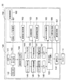
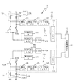
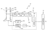
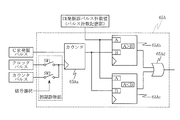
- FIG. 2 is a block diagram illustrating a configuration of the torque detection device 30.
- the torque detection device 30 includes the torque sensor 3 described above.
- signal processing is performed on the output signal of the coil pair when the excitation signal is supplied to the coil pair constituting the torque sensor 3.
- 2 shows a signal processing circuit (signal processing unit) 140 that outputs a torque detection signal and a diagnostic device 160 that includes a monitoring unit that monitors an abnormality in each block of the signal processing circuit 140.
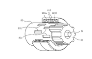
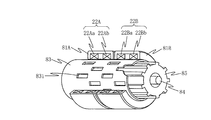
- the torque sensor 3 includes a coil pair in which the first coil 22 ⁇ / b> Aa and the second coil 22 ⁇ / b> Ab are combined, a yoke 81 in which the coils 22 ⁇ / b> Aa and 22 ⁇ / b> Ab are wound, and a cylindrical member 83. And a plurality of windows 831 provided on the outer periphery of the cylindrical member 83 so as to face the coil pair, a torsion bar 84, and a sensor shaft 85.
- the torsion bar 84, the sensor shaft 85, and the input shaft 2a and the output shaft 2b of the steering shaft 2 are arranged coaxially.
- the signal processing circuit 140 mainly includes a clock unit, an excitation unit, a sensor unit, a signal processing unit, and a communication output unit.
- the clock unit includes a CLK 141 configured with, for example, a commercially available clock (such as a crystal oscillator).
- the clock unit divides the clock signal based on the clock signal output from the CLK 141 and the specified frequency (A [Hz] or B [Hz]) selected by the SEL 142 and outputs the specified frequency ( A counter 143 for converting to an excitation frequency).
- the excitation pulse output from the counter 143 is input to the excitation waveform generation unit 144 constituting the excitation unit.
- the excitation waveform generation unit 144 generates an excitation signal having a frequency selected from A [Hz] and B [Hz] based on the excitation pulse input from the counter 143, and outputs the excitation signal to the sensor unit.
- the generated excitation signal is supplied to a main bridge circuit (bridge MAIN) 145 and a sub-bridge circuit (bridge SUB) 149 constituting the sensor unit.
- the main bridge circuit 145 includes a coil pair including a first coil and a second coil.
- the main differential amplifier 146 When an excitation signal is supplied to the coil pair, the main differential amplifier 146 has a terminal voltage between the first coil and the second coil. Difference (terminal voltage difference) is amplified and output. This output signal is input to the main rectifying / smoothing circuit 147, and the main rectifying / smoothing circuit 147 rectifies and smoothes the output.
- the low-pass filter (LPF) 148 removes noise from the smoothed output and outputs the noise to the torque calculation circuit 153 constituting the signal processing unit.
- the operations of the sub-bridge circuit 149, the sub-differential amplifier 150, the sub-rectifying / smoothing circuit 151, and the LPF 152 are the same as the operations from the main bridge circuit 145 to LPF 148, and thus the description thereof is omitted here.
- the torque calculation circuit 153 includes a multiplexer (MUX) and an AD converter (ADC), and obtains a torque detection signal based on signals (MAIN torque value, SUB torque value) output from the LPFs 148 and 152. Is output to the communication output circuit 154 constituting the communication output unit.
- the communication output circuit 154 outputs the torque detection signal obtained by the torque calculation circuit 153 to the controller (ECU) 15.
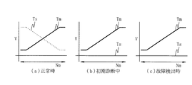
- the monitoring unit of the diagnostic device 160 includes an excitation pulse monitoring unit 161 that monitors the excitation pulse, an excitation signal monitoring unit 162 that monitors the waveform of the excitation signal (frequency, DUTY, shape, offset, reduction, excessive oscillation, etc.) , A phase monitoring unit 163 that monitors the phase of the excitation signal, a differential amplitude monitoring unit 164 that monitors the amplitude of the signal output from the differential amplifier 150, and a MUX / MUX that monitors abnormalities in the MUX and ADC of the torque calculation circuit 153.
- excitation pulse monitoring unit 161 that monitors the excitation pulse
- an excitation signal monitoring unit 162 that monitors the waveform of the excitation signal (frequency, DUTY, shape, offset, reduction, excessive oscillation, etc.)
- a phase monitoring unit 163 that monitors the phase of the excitation signal
- a differential amplitude monitoring unit 164 that monitors the amplitude of the signal output from the differential amplifier 150
- An ADC monitoring unit 165 a torque signal monitoring unit 166 that monitors a torque detection signal output from the torque calculation circuit 153, and a communication monitoring unit 167 that monitors an abnormality of the communication output unit 154 are provided. During the execution of the steering assist control, various monitoring processes are regularly performed by these monitoring units, and when any abnormality is detected, these are immediately transmitted to the ECU 15.
- the diagnosis device 160 includes an initial diagnosis unit 168 for diagnosing each of the monitoring units themselves.
- This initial diagnosis unit 168 operates immediately after the power is turned on (or immediately after the ignition switch 18 is turned on), before the ECU 15 side starts the steering assist control, and whether or not each monitoring unit itself operates normally. Make an initial diagnosis.
- each monitoring unit is sequentially subjected to diagnosis.
- the ECU 15 is disabled from using the torque sensor signal by setting an initial diagnosis flag (to prevent the steering assist control from being performed).
- the initial diagnosis unit 168 alternately inputs a normal signal and an abnormal signal as initial diagnosis signals to the monitoring unit to be diagnosed, and the monitoring unit is operating normally.
- the normal signal is a signal in which the diagnosis result by the monitoring block functioning normally is “normal” (normally diagnosed) when the signal is the monitoring target signal, and the abnormal signal is When the signal is a monitoring target signal, the diagnosis result by the monitoring block functioning normally is “abnormal” (abnormal diagnosis is performed).
- the switch SW1 In the normal monitoring state (steady diagnosis mode), as shown in FIG. 4, the switch SW1 is turned on and a normal monitoring target signal (normal signal) is input to the monitoring block, and the normal signal is diagnosed.
- signals for initial diagnosis are input to the monitoring block by switching on / off of the switches SW1 to SW3 by a switching signal.
- normal signals ⁇ abnormal signals ⁇ normal signals are sequentially input as signals for initial diagnosis.
- the switch SW2 When a normal signal is input, the switch SW2 is turned on.
- the switch SW3 When an abnormal signal is input, the switch SW3 is turned on.
- the output of the monitoring block is “0” during normal diagnosis and “1” during abnormality diagnosis, and the output of this monitoring block is input to the AND circuit.
- the AND circuit takes an AND of the output of the monitoring block and the flag mask Mask, and outputs this as a final output signal of the monitoring unit.
- the flag mask Mask is for selecting a monitoring unit to be diagnosed.
- the Mask of all the monitoring blocks is “OFF (1)”.
- the Mask of other monitoring blocks not to be diagnosed is “ON (0)”.
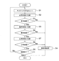
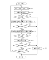
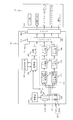
- FIG. 5 is a flowchart showing an initial diagnosis processing procedure executed by the initial diagnosis unit 168.
- this initial diagnosis process is executed immediately after the power is turned on and prior to the steering assist control by the ECU 15.
- the initial diagnosis unit 168 “OFF (1)” only the flag mask of the monitoring block to be initially diagnosed, and “ON (0)” the flag mask of other monitoring blocks.
- the output of the other monitoring units (AND output in FIG. 4) is set to “0” regardless of the output of the monitoring block (monitoring).
- Block monitoring function can be disabled).
- the monitoring blocks that require the flag mask are the monitoring blocks of the excitation pulse monitoring unit 161, the excitation signal monitoring unit 162, the phase monitoring unit 163, the differential amplitude monitoring unit 164, and the torque signal monitoring unit 166.
- step S2 the initial diagnosis unit 168 sets the initial diagnosis normal state by inputting a normal signal for initial diagnosis to the monitoring block to be initially diagnosed (turns on the switch SW2 in FIG. 4), and proceeds to step S3. .
- step S3 the initial diagnosis unit 168 waits until the normal state of the initial diagnosis is stabilized, and then confirms the outputs of all the monitoring units, and can confirm that all outputs are “0” and no abnormality has occurred. It is determined whether or not. At this time, if it is confirmed that an abnormality has occurred, it is determined that there is an abnormality in the monitoring function of the monitoring unit, the process proceeds to step S4, and predetermined abnormality processing (the abnormality of the communication output circuit 154 is detected). Notification etc.) and the initial diagnosis process is terminated.
- predetermined abnormality processing the abnormality of the communication output circuit 154 is detected. Notification etc.
- step S3 determines whether abnormality has occurred. If it is confirmed in step S3 that no abnormality has occurred, the process proceeds to step S5, and the initial diagnosis unit 168 inputs an initial diagnosis abnormality signal to the monitoring block to be initially diagnosed (FIG. 4). The switch is switched to the initial diagnosis abnormal state by turning on the switch SW3.
- step S6 the initial diagnosis unit 168 waits until the initial diagnosis abnormal state is stabilized, then checks the outputs of all the monitoring units, and the output of only the monitoring unit to be diagnosed is “1”. It is determined whether or not the occurrence has been confirmed. At this time, if it cannot be confirmed that an abnormality has occurred, it is determined that there is an abnormality in the monitoring function of the monitoring unit, and the process proceeds to step S4.
- step S6 determines whether an abnormality has occurred. If it is confirmed in step S6 that an abnormality has occurred, the process proceeds to step S7, and the initial diagnosis unit 168 inputs a normal signal for initial diagnosis to the initial diagnosis target monitoring block (FIG. 4). Is switched to the initial diagnosis normal state.
- step S8 the initial diagnosis unit 168 waits until the normal state of the initial diagnosis is stabilized, and then confirms the outputs of all the monitoring units. All outputs are “0” and no abnormality has occurred. It is determined whether it has been confirmed. When it is confirmed that an abnormality has occurred, it is determined that there is an abnormality in the monitoring function of the monitoring unit, and the process proceeds to step S4. On the other hand, if it is confirmed in step S8 that no abnormality has occurred, the process proceeds to step S9.
- step S9 the initial diagnosis unit 168 determines whether or not the initial diagnosis of all the monitoring units has been completed. If there is a monitoring unit that has not executed the initial diagnosis, the initial diagnosis unit 168 switches the initial diagnosis target. If the initial diagnosis of all the monitoring units has been completed, the initial diagnosis process is terminated as it is.
- the initial diagnosis function for diagnosing the monitoring unit itself is provided, the reliability of the monitoring function of the monitoring unit can be improved. That is, although the signal processing circuit 140 has an abnormality, the monitoring unit cannot detect the abnormality, or the signal processing circuit 140 is normal, but the abnormality has occurred in the monitoring unit. It is possible to prevent a false detection. Therefore, it is possible to prevent the occurrence of problems associated with erroneous detection by the monitoring unit.
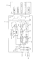
- FIG. 6 is a diagram illustrating a configuration of the excitation signal monitoring unit 162. Here, portions corresponding to the monitoring block and the AND circuit in FIG. 4 are shown.
- the excitation signal monitoring unit 162 monitors the waveform of the excitation signal.
- the excitation signal output from the excitation waveform generation unit 144 is input to the input terminal 162a as a normal signal.
- an excitation signal having an ideal waveform is input to the input terminal 162a as a normal signal for initial diagnosis.
- an excitation signal for example, a 1/2 frequency
- an excitation signal for example, a 1/2 frequency
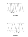
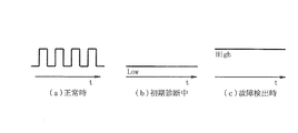
- FIG. 7 is a diagram showing signal waveforms for initial diagnosis, where (a) shows a normal signal and (b) shows an abnormal signal.
- the excitation signal monitoring unit 62 counts a period T1 from when the monitored signal becomes equal to or higher than the threshold value V1 until it becomes equal to or lower than the threshold value V2, and a period T2 from when it becomes lower than the threshold value V2 until it becomes equal to or higher than the threshold value V1. Diagnosis is made by comparing these with normal values.
- the threshold value V1 is 4.25V
- the threshold value V2 is 0.75V.
- the signal input to the input terminal 162a is input to the comparators 162b and 162c.
- the comparator 162b compares the input signal with the threshold value V1, and outputs a signal that becomes H level when the input signal is equal to or higher than the threshold value V1.
- the comparator 162c compares the input signal with the threshold value V2, and outputs a signal that becomes H level when the input signal is equal to or lower than the threshold value V2.
- the output signals of the comparators 162b and 162c are input to the counter circuits 162d and 162e, respectively.
- the counter circuit 162d Based on the output signals of the comparators 162b and 162c, the counter circuit 162d counts a period T1 from when the input signal becomes equal to or higher than the threshold value V1 until it becomes equal to or lower than the threshold value V2, and outputs the result to the comparison circuit 162f. .
- the counter circuit 162e counts a period T2 from the time when the input signal becomes equal to or lower than the threshold value V2 to the time when the input signal becomes equal to or higher than the threshold value V1, based on the output signals of the comparators 162b and 162c. Output.
- the comparison circuit 162f compares the period T1 with the normal value T0, and outputs a signal that is “1” when the counted period T1 is different from the normal value T0.
- the comparison circuit 162g compares the period T2 with the normal value T0, and outputs a signal that is “1” when the counted period T2 is different from the normal value T0.
- the output signals of the comparison circuits 162f and 162g are input to the OR circuit 162h.
- the output of the OR circuit 162h is latched by the latch circuit 162i, and input to the AND circuit 162k at the timing specified by the determination timing generation unit 162j.
- the diagnosis is performed in the initial diagnosis abnormal state.
- the abnormal signal shown in FIG. 7B is input from the input terminal 162a.
- a period T1 from the threshold V1 to the threshold V2 and a period T2 from the threshold V2 to the threshold V1. are different from the normal value T0. Therefore, the output of the latch circuit 162i is “1”, and the output of the AND circuit 162k is also “1”.
- a period T1 from the threshold V1 to the threshold V2 and a period T2 from the threshold V2 to the threshold V1 May be equal to the normal value.
- the output of the latch circuit 162i is “0”, and the output of the AND circuit 162k is also “0”.
- the diagnosis in the initial diagnosis normal state is performed, and whether the abnormality is correctly diagnosed when the abnormality signal is input (whether the output of the AND circuit 162k is “1”).
- the output of the AND circuit 162k is not “1”, it is determined that the excitation signal monitoring unit 162 is not functioning normally.
- the diagnosis is performed again in the initial diagnosis normal state. That is, the normal signal shown in FIG. 7A is input again from the input terminal 162a, and it is confirmed whether the normal diagnosis is correctly performed (whether the output of the AND circuit 162k is “0”).
- the normal diagnosis is performed correctly, but the input switching of the initial diagnosis signal is performed normally. If not, normal diagnosis is not performed even if the excitation signal monitoring unit 162 functions normally. Therefore, it is possible to confirm whether the initial diagnosis function is operating normally by inputting the normal signal again and performing the initial diagnosis after the normal signal and the abnormal signal.
- the threshold value V1 smaller than the maximum value of the monitoring target signal and the threshold value V2 ( ⁇ V1) larger than the minimum value of the monitoring target signal are prepared and become equal to or higher than the threshold value V1.
- a method is used to determine whether or not a period T1 until the threshold value V2 is equal to or less than the threshold value V2 and a period T2 between the threshold value V2 and the threshold value V1 is equal to or greater than the threshold value V1.
- a signal having a frequency different from that of the normal signal is used as the abnormal signal for initial diagnosis.
- the periods T1 and T2 when the abnormal signal is the monitoring target signal can be set to a value different from the normal value. Therefore, by using such a signal, it is possible to appropriately determine whether or not the excitation signal monitoring unit 162 is functioning normally.
- An abnormal signal for initial diagnosis can be generated by using the 1/2 frequency output function of the excitation pulse generation function. Thus, an appropriate abnormal signal can be generated relatively easily.
- FIG. 8 is a diagram illustrating a configuration of the phase monitoring unit 163. Here, only the part corresponding to the monitoring block in FIG. 4 is shown.
- the phase monitoring unit 163 monitors a phase shift between the torque detection signal and the excitation signal in the steady diagnosis mode. Particularly in the case of a coil-type torque sensor, when an abnormality occurs in the coil sensor unit, the torque detection signal may shift in phase with respect to the excitation signal. Therefore, when the excitation signal and the torque detection signal are out of phase and an amplitude greater than a certain level is generated in the torque detection signal, it is determined that an abnormality has occurred in the torque detection signal.
- the monitoring block includes three comparators 163a to 163c and an AND circuit 163d to which the outputs of the comparators 163a to 163c are input.
- the comparator 163a compares the excitation signal input from the input terminal 163e with the threshold value V3, and outputs a signal that becomes H level when the excitation signal is equal to or higher than the threshold value V3.
- the comparator 163b compares the excitation signal input from the input terminal 163e with the threshold value V4, and outputs a signal that becomes H level when the excitation signal is equal to or less than the threshold value V4.
- the comparator 163c compares the monitoring target signal with the threshold value V3, and outputs a signal that becomes H level when the monitoring target signal is equal to or lower than the threshold value V3.
- a torque detection signal is input to the comparator 163c as a monitoring target signal (switch SW4 is turned on).
- the normal signal for the initial diagnosis becomes the monitoring target signal
- the excitation signal is input to the comparator 163c as the normal signal (switch SW5 is turned on).
- an abnormal signal for initial diagnosis becomes a monitoring target signal, and a signal obtained by shifting the phase of the excitation signal through the phase shift circuit 163f is input to the comparator 163c as the abnormal signal (switch).
- SW6 is turned on).
- the phase shift circuit 163f is a circuit that shifts the phase of the excitation signal by 90 degrees, and is configured by an operational amplifier, for example.
- the threshold values V3 and V4 are set between the minimum value and the maximum value of the amplitude of the excitation signal, and V3 ⁇ V4.
- the threshold value V3 is set to 1.75V
- the threshold value V4 is set to 2.75V.
- the phase difference may be other than 90 degrees.
- the output of the AND circuit 163d is counted during the period when it is at the H level and is compared with a normal value.
- a signal that is “1” indicating that an abnormality has occurred in the torque detection signal is input to a circuit corresponding to the AND circuit in FIG. 4.
- the output (CP1 output) of the comparator 163a is at the H level only during the period when the excitation signal a is equal to or higher than the threshold value V3.
- the output of the comparator 163b (CP2 output) is at the H level only during the period when the excitation signal a is equal to or lower than the threshold value V4.
- the output of the comparator 163c (CP3 output) is at the H level only during the period when the monitoring target signal (torque detection signal b) is equal to or lower than the threshold value V3.
- the monitoring block is not functioning normally, the monitoring target signal is misrecognized as phase-shifted with respect to the excitation signal, and there is a period during which the output of the AND circuit 163d is at the H level. .
- the initial diagnosis is performed in the normal state first, and it is confirmed whether the normal diagnosis is correctly performed when the normal signal (excitation signal) is input (whether the output of the AND circuit 163d is always “0”). . At this time, if the output of the AND circuit 163d is not always “0”, it is determined that the phase monitoring unit 163 is not functioning normally.
- the diagnosis is performed in the initial diagnosis abnormal state.
- the switch SW6 in FIG. 8 is turned on, and a signal obtained by shifting the phase of the excitation signal is input to the comparator 163c as an abnormal signal for initial diagnosis.
- the monitoring target signal and the excitation signal have different phases, when the monitoring block functions normally, there is a period during which the output of the AND circuit 163d is at the H level.
- the monitoring block is not functioning normally, the monitoring target signal and the excitation signal may be erroneously recognized as having the same phase, and the output of the AND circuit 163d may always be “0”.
- the diagnosis in the initial diagnosis abnormal state is performed following the diagnosis in the normal initial diagnosis state, and whether the abnormality is correctly diagnosed when the abnormality signal is input (whether the output of the AND circuit 163d is at the H level). Confirm.
- the output of the AND circuit 163d is always “0”, it is determined that the phase monitoring unit 163 is not functioning normally.
- phase monitoring method there are three phases in which the output becomes H level during the period in which the excitation signal is greater than or equal to the threshold value V3, the period in which the excitation signal is less than or equal to the threshold value V4, Comparators 163a to 163c are prepared, and a method of determining whether or not the period during which all the outputs of the three comparators 163a to 163c are at the H level is a normal value or more is used.
- a signal having a phase different from that of the normal signal is used as the abnormal signal for initial diagnosis.
- the phase difference between the normal signal and the abnormal signal is set to, for example, 90 degrees, when the abnormal signal is the monitoring target signal, it is possible to ensure a period in which all the outputs of the three comparators 163a to 163c are at the H level.
- the normal value can be exceeded. Therefore, by using such a signal, it is possible to appropriately determine whether or not the phase monitoring unit 163 functions normally.
- the abnormal signal is generated by shifting the phase of the normal signal via the phase shift circuit, an appropriate abnormal signal can be obtained relatively easily.
- FIG. 10 is a diagram illustrating a configuration of the MUX / ADC monitoring unit 165. Here, only the part corresponding to the monitoring block in FIG. 4 is shown.
- the MUX / ADC monitoring unit 165 determines that an abnormality has occurred in the MUX and ADC when the ADC output value is different from the expected value, and outputs a signal that is “1”.
- a plurality of voltage values (VCC * 1/2, VCC * 1/3, VCC * 2/3, VCC * 3/3, VCC * 0 /) in the normal use range (0 to VCC) are monitored signals. Using 3), these ADC output values are compared with their respective expected values.
- the monitoring block includes a MUX 165a and an ADC 165b.
- VCC * 1/3, VCC * 2/3, VCC * 1/2, VCC * 3/3, and VCC * 0/3 are input to the MUX 165a.
- the MUX 165a sequentially selects these signals according to the Mux selection signal and outputs them to the ADC 165b.
- the ADC 165b performs AD conversion on the signal input from the MUX 165a and outputs the AD signal to the latch circuit 165c corresponding to the input signal.
- the main torque value and the sub torque value latched by the latch circuit 165c are output to the communication output circuit 154 described above.
- the ADC output value of each voltage value latched by the latch circuit 165c is output to the comparison circuit 165d.
- the comparison circuit 165d compares each ADC output value with the expected value, and outputs the result to the OR circuit 165e.
- the output of the OR circuit 165e is “1” when at least one of the ADC output values is “1”.
- the output of the OR circuit 165e is latched by the latch circuit 165f, and is input to a circuit corresponding to the AND circuit of FIG. 4 at a timing specified by the determination timing generation unit 165g.
- the input signal selection command is a command signal that turns on the lower stage of each switch in the normal diagnosis mode and the initial diagnosis normal state, and turns on the upper stage of each switch in the initial diagnosis abnormal state.
- VCC * 1/3 and VCC * 2/3, VCC * 3/3 and VCC * 0/3 are interchanged and input to MUX 165a, and VCC * 1 / VCC * 2/3 is input from the second input terminal. Therefore, when the ADC output value is monitored in this state, the output value of the comparison circuit 165d becomes “1” indicating abnormality, and the output of the OR circuit 165e also becomes “1” indicating abnormality.
- the torque output value is equal to 1/2 VCC. Even if an abnormality occurs in the MUX 165a or the ADC 165b, the ADC output value is the same as that at the neutral time. For this reason, when an abnormality occurs in the MUX 165a or the ADC 165b, there is a possibility that the neutral state is erroneously detected even if the torque output is actually made. Further, in the initial diagnosis, when only 1 ⁇ 2 VCC is used as a normal signal, it is erroneously determined to be normal even if an abnormality occurs in the MUX 165a or the ADC 165b.
- initial diagnosis is performed not only in 1/2 VCC but also in a normal use area such as 1/3 VCC or 2/3 VCC. Therefore, it is possible to appropriately diagnose whether or not the MUX / ADC monitoring unit 165 is functioning normally. Therefore, it can be prevented that the neutral state is erroneously detected although the torque output is actually performed.
- the initial diagnosis method of the monitoring unit a method of inputting a normal signal and an abnormal signal alternately and confirming that the normal diagnosis is performed when the normal signal is input and the abnormal diagnosis is performed when the abnormal signal is input is adopted. It is possible to appropriately check whether the unit is operating normally. Furthermore, after normal signals and abnormal signals are input, normal signals are input again and initial diagnosis is performed, so that the initial diagnosis function operates normally, such as whether input switching of the initial diagnosis signals is performed normally. Can also be confirmed appropriately. (Modification) In the first embodiment, when a redundant system such as a backup function is configured, a selection function such as not using the system on the side where an abnormality has occurred can be provided.
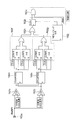
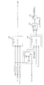
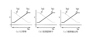
- FIG. 11 is a block diagram illustrating a configuration of the torque detection device 30.
- the torque detection device 30 includes the torque sensor 20 described above.
- the torque sensor 20 includes two pairs of coils 22A and 22B. Further, as shown in FIG. 12, the torque sensor 20 has a first yoke 81 ⁇ / b> A, a second yoke 81 ⁇ / b> B, a cylindrical member 83, and a coil member 22 ⁇ / b> A, 22 ⁇ / b> B facing the outer peripheral portion of the cylindrical member 83.
- a plurality of windows 831, a torsion bar 84, and a sensor shaft 85 are provided.
- the torsion bar 84, the sensor shaft 85, and the input shaft 2a and the output shaft 2b of the steering shaft 2 are arranged coaxially.
- the coil pair (first coil pair) 22A is formed by combining a pair of coils 22Aa and 22Ab of the same standard to form a coil pair, and is arranged in a cylindrical first yoke 81A as shown in FIG. .
- the coil pair (second coil pair) 22B is formed by combining a pair of coils 22Ba and 22Bb of the same standard to form a coil pair. As shown in FIG. Be placed.
- the torque detection device 30 includes signal processing circuits (signal processing units) 59A and 59B that are provided corresponding to the first coil pair 22A and the second coil pair 22B, respectively, and that process the output signals of the coil pairs.
- the signal processing circuits 59A and 59B are provided in the controller 15.
- the torque detection device 30 includes clock signal generation circuits (CLK) 62A and 62B that output clock signals that are sources of sine waves generated by the excitation signal generation units 60A and 60B. Clock signals generated by the clock signal generation circuits 62A and 62B are supplied to the excitation signal generation units 60A and 60B.
- CLK clock signal generation circuits
- the clock signal generation circuits 62A and 62B for example, an inexpensive clock oscillator such as a CR oscillator is applied.
- a frequency fluctuation exceeding an allowable frequency range for example, ⁇ 20%
- the abnormality detectors 64A and 64B for detecting whether or not the frequency fluctuation of the clock signal generated by the clock signal generation circuits 62A and 62B is within an allowable range are required.
- each of the abnormality detection units 64A and 64B includes a low-pass filter (monitoring low-pass filter) 68 to which the sine wave signals output from the excitation signal generation units 60A and 60B are supplied, and the low bus
- a clock frequency fluctuation monitoring unit 69 that detects amplitude fluctuation of the filter output VF output from the filter 68 to detect the frequency fluctuation of the clock signal is provided.
- the low pass filter 68 includes a resistor R1 and a capacitor C1.
- the cut-off frequency fc of the low-pass filter 68 is set to a value in the vicinity of 6 kHz, for example, and attenuates a sine wave signal based on a clock signal set to a frequency of 9 kHz, for example.
- the reason why the cut-off frequency fc of the low-pass filter 68 is set to a value in the vicinity of 6 kHz is that, for example, when a frequency fluctuation width of ⁇ 20% is monitored with respect to an excitation signal of 9 kHz,
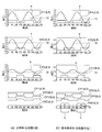
- the relationship between the cut-off frequency fc and the differential voltage between the peak value at 9 kHz is as shown in FIG.
- the characteristic curve L1 in the range from 7.2 kHz to 9 kHz, which is ⁇ 20% of 9 kHz.
- the difference voltage peaks at 5895 Hz.
- the differential voltage peaks at 6631 Hz as shown by the characteristic curve L2.
- the frequency fluctuation is changed to the amplitude fluctuation by selecting 6 kHz, which is approximately between the peaks of the characteristic curves L1 and L2, as the cut-off frequency fc of the low-pass filter 68 when monitoring the frequency fluctuation width of ⁇ 20%. Can be replaced efficiently.
- the filter output VF of the low-pass filter 68 has the frequency of the clock signal. Variation appears as amplitude variation. That is, if it is set that the frequency variation of the clock signal is within ⁇ 20%, when the frequency variation of the clock signal is within ⁇ 20%, as shown in FIG. 15B, the filter output VF The peak value in the upper half wave falls within the range of the upper limit voltage set value VH (eg, 3.87 V) and the lower limit voltage set value VL (eg, 3.55 V).
- the peak value of the filter output VF is the upper limit voltage as shown in FIG.
- the upper limit error exceeds the set value VH.
- the peak value of the filter output VF becomes lower than the lower limit voltage setting value VL as shown in FIG.
- the lower limit is abnormal.
- the clock frequency fluctuation monitoring unit 69 determines whether or not the peak voltage of the filter output VF of the low-pass filter 68 is within the normal range of the upper limit voltage setting value VH and the lower limit voltage setting value VL. It is possible to accurately detect whether or not the frequency fluctuation is within an allowable range. Therefore, as shown in FIG. 13, the clock frequency fluctuation monitoring unit 69 includes a window comparator 69a and a logic circuit 69b connected to the output side of the window comparator 69a.
- the window comparator 69a includes a voltage dividing circuit VD that divides a DC power supply and two comparators CP1 and CP2.
- the voltage dividing circuit VD has three resistors R1, R2, and R3 connected in series between the DC power supply terminal VDD and the ground.
- the aforementioned upper limit voltage set value VH is obtained from the connection point of the resistors R1 and R2, and the aforementioned lower limit voltage set value VL is obtained from the connection point of the resistors R2 and R3.
- the filter output VF of the low-pass filter 68 is input to the non-inverting input side, and the upper limit voltage setting value VH output from the voltage dividing circuit VD is input to the inverting input side.
- the comparator CP2 receives the filter output VF of the low-pass filter 68 on the inverting input side and the lower limit voltage setting value VL output from the voltage dividing circuit VD on the non-inverting input side.
- the output signal Scp1 of the comparator CP1 is set to the upper limit voltage. While the value VH is exceeded, the output signal Scp2 of the comparator CP2 becomes high level while the filter output VF exceeds the lower limit voltage set value VL.
- the output signal Scp1 of the comparator CP1 and the output signal Scp2 of the comparator CP2 are Both maintain the low level.
- the output signal Scp1 of the comparator CP1 is at a low level and the output signal Scp2 of the comparator CP2 is at a high level.
- the logic circuit 69b includes a NAND gate NG1 to which the output signal Scp1 of the comparator CP1 is input to the two input sides, a NAND gate NG2 to which the output signal of the NAND gate NG1 and the output signal Scp2 of the comparator CP2 are input to the two input sides. It consists of Therefore, the logic circuit 69b outputs a low level detection signal from the NAND gate NG2 when the frequency component of the clock signal is within the normal range, and an abnormal state in which the frequency fluctuation of the clock signal is below or above the normal range is large. When this happens, a high level detection signal is output from the NAND gate NG2.
- one terminal of the coils 22Aa and 22Ab constituting the first coil pair 22A is connected to the excitation signal generator 60A via the electric resistors 61Aa and 61Ab, respectively.
- the other terminals of the coils 22Aa and 22Ab constituting the first coil pair 22A are grounded. Accordingly, a bridge circuit is configured by the coils 22Aa and 22Ab and the resistors 61Aa and 61Ab.
- one terminal of the coils 22Ba and 22Bb constituting the second coil pair 22B is connected to the excitation signal generator 60B via the electric resistors 61Ba and 61Bb, respectively.
- the other terminals of the coils 22Ba and 22Bb constituting the second coil pair 22B are grounded.
- a bridge circuit is comprised by coil 22Ba, 22Bb and resistance 61Ba, 61Bb.
- the output signal of the first coil pair 22A that is, the difference signal of the bridge circuit is output to the signal processing circuit 59A.
- the output signal of the second coil pair 22B that is, the difference signal of the bridge circuit is output to the signal processing circuit 59B.
- the signal processing circuit 59A includes a differential amplifier 51A, a rectifying / smoothing circuit 52A, and a noise removal filter 54A.
- the signal processing circuit 59B includes a differential amplifier 51B, a rectifying / smoothing circuit 52B, and a noise removal filter 54B.
- the differential amplifier 51A amplifies and outputs the output difference between the coils 22Aa and 22Ab constituting the first coil pair 22A, that is, the difference between the terminal voltages of the coils 22Aa and 22Ab (terminal voltage difference).
- the rectification / smoothing circuit 52A rectifies and smoothes the output of the differential amplifier 51A and outputs the result.
- the output of the rectification / smoothing circuit 52A passes through the noise removal filter 54A to remove noise, and the result is input to the torque calculation unit 56A.
- the torque calculators 56A and 56B perform a predetermined calculation based on outputs (for example, average values) of the noise removal filter 54A and the noise removal filter 54B to obtain a steering torque generated in the steering system.
- the electric motor control unit 57 is provided in the ECU, and supplies the electric motor 12 with a drive current that can generate a steering assist torque that reduces the steering torque by the driver based on the calculation results of the torque calculation units 56A and 56B.
- the torque detection device 30 is made redundant by a first torque detection system using the first coil pair 22A and the signal processing circuit 59A and a second torque detection system using the second coil pair 22B and the signal processing circuit 59B.
- the electric motor 12 is controlled to perform steering assist control based on the steering torque detected by the first torque detection system or the second torque detection system.
- the system is switched to the system in which the problem does not occur, and the detection of the steering torque is continued, and the steering assist control is continued.
- the abnormality detectors 64A and 64B described above regularly change the frequency of the clock signal. Monitor for abnormalities.
- the abnormality detection units 64A and 64B include the clock frequency fluctuation monitoring unit 69 having the low-pass filter 68 and the window comparator 69a.
- the clock frequency fluctuation monitoring unit 69 detects the frequency fluctuation of the clock signal as the amplitude fluctuation of the filter output VF of the low-pass filter 68.
- the output signal output from the clock frequency fluctuation monitoring unit 69 is at a low level.
- the output signal output from the clock frequency fluctuation monitoring unit 69 becomes high level.
- a method of separately providing a monitoring clock signal generation circuit and monitoring the correctness of the clock frequency from the difference between the two is used.
- this method in order to monitor the accuracy of the clock frequency of the clock signal generation circuits 62A and 62B, a highly accurate clock must be prepared as a monitoring clock, which increases costs and increases the cost.
- an abnormality occurs in the precision clock signal generation circuit, the abnormality in the high precision clock signal generation circuit cannot be detected.
- an inexpensive CR oscillator can be applied as the clock signal generation circuits 62A and 62B.
- the clock frequency is monitored by a clock constituted by the low-pass filter 68 and the window comparator 69a. This can be performed with the frequency fluctuation monitoring unit 69. Therefore, it is not necessary to provide an expensive clock signal generation circuit for monitoring, and the cost can be reduced accordingly.
- the low-pass filter 68 has a primary filter configuration using the resistor RO and the capacitor C0 has been described.
- the present invention is not limited to this, and has a second or higher filter order.
- the filter configuration With the filter configuration, the attenuation characteristic shown in FIG. 15A can be made steeper, and the amplitude fluctuation range of the filter output VF due to the frequency fluctuation and the design value of the element accuracy constituting the low-pass filter can be reduced. The degree of freedom can be further improved.
- the abnormality detection units 64A and 64B include monitoring unit diagnosis units 71A and 71B having an initial diagnosis function for diagnosing whether or not the clock frequency fluctuation monitoring unit 69 is operating normally. Prepare. This initial diagnosis is activated immediately after the controller 15 is turned on (or immediately after the ignition switch 18 is turned on), and before the controller 15 starts the steering assist control. During the initial diagnosis, the controller 15 is disabled from using the torque sensor signal by setting an initial diagnosis flag (to prevent the steering assist control from being performed).
- the monitoring unit diagnosis unit 71A includes a clock frequency selection circuit 72A (or 72B) between the clock signal generation circuit 62A (or 62B) and the excitation signal generation unit 60A (or 60B).
- the clock frequency selection circuit 72A includes three switches SWa, SWb, and SWc that are connected in parallel and connected at one end to the clock signal generation circuit 62A (or 62B), in addition to the switches SWa, SWb, and SWc.
- Dividing circuits 73a, 73b and 73c individually connected to the ends are provided.
- the clock signals output from the frequency dividing circuits 73a, 73b, and 73c are input to the excitation signal generation unit 60A (or 60B).
- the frequency dividing circuit 73a forms the above-described normal clock signal CPu having the reference frequency fb of 9 kHz, which is used at the normal time. Further, the frequency dividing circuit 73b forms an abnormal low frequency clock signal CPaL set to a frequency lower than the allowable lower limit range ( ⁇ 20%) lower than the normal clock signal CPu. Further, the frequency dividing circuit 73c forms an abnormal high frequency clock signal CPaH whose frequency is set to be higher than the allowable upper limit range (+ 20%) than the normal clock signal CPu.
- the monitoring unit diagnosis unit 71A includes comparators CP1 and CP2 of the window comparator 69a of the clock frequency fluctuation monitoring unit 69.
- the comparator CP1 includes a peak value of the upper half wave of the filter output VF output from the low pass filter 68 after the abnormal low frequency clock signal CPaL is converted into a sine wave by the excitation signal generators 60A and 60B.
- the predetermined high set voltage V1 shown in FIG. 15B is input which is lower than the lower limit voltage set value VL and lower than the lower limit voltage set value VL.
- the comparator CP2 receives the peak value of the lower half wave of the filter output VF output from the low-pass filter 68 after the abnormal high frequency clock signal CPaH is converted into a sine wave by the excitation signal generators 60A and 60B. Is inputted with a predetermined low set voltage V2 shown in FIG.
- the comparison output of the comparator CP1 is input to the upper half-wave diagnostic unit 74U that diagnoses based on the upper side of the amplitude of the excitation signal, and the comparison output of the comparator CP2 is diagnosed based on the lower side of the amplitude of the excitation signal.
- the signal is input to the side half-wave diagnostic unit 74L.
- the upper half-wave diagnostic unit 74U includes a counter 75U that receives the comparison output of the comparator CP1 and counts the clock signal during the high level period.
- the upper half wave of the filter output VF output from the low pass filter 68 is An abnormal clock period T1 that is a count value CU corresponding to a period when the voltage is equal to or higher than a predetermined high setting voltage V1 is input to the comparators CPU1 and CPU2.
- the comparator CPU1 outputs a high-level comparison signal when the abnormal clock period T1 is larger than the count value CU.
- the comparator CPU2 outputs a high level comparison signal when the normal clock period T1 is smaller than the count value CU.
- the comparison signals output from the comparators CPU1 and CPU2 are supplied to the latch circuit 77U, and the comparison signal is latched by the latch circuit 77U based on the timing signal supplied from the determination timing generation circuit 78U.
- the latch signal latched by the latch circuit 77U is supplied to an AND gate 79U to which a mask signal that becomes a high level only at the time of initial diagnosis is input.
- the normal flag Fn1 is abnormal.
- the normal flag Fn1 is set to “1” indicating normal.
- the lower half-wave diagnostic unit 74L has a counter 75L that receives the comparison output of the comparator CP2 and counts the clock signal during the high level period. After the count value CL of the counter 75L converts the abnormal high frequency clock signal CPaH described above into a sine wave by the excitation signal generator 60A (or 60B), the lower half wave of the filter output VF output from the low pass filter 68 is obtained.
- An abnormal clock period T2 that is a count value CL corresponding to a period during which the voltage is equal to or lower than a predetermined low set voltage V2 is input to the comparators CPL1 and CPL2.
- the comparator CPL1 outputs a high-level comparison signal when the abnormal clock period T2 is larger than the count value CL.
- the comparator CPL2 outputs a high level comparison signal when the abnormal clock period T2 is smaller than the count value CL.
- the comparison signals output from the comparators CPL1 and CPL2 are supplied to the latch circuit 77L, and the comparison signal is latched by the latch circuit 77L based on the timing signal supplied from the determination timing generation circuit 78L.
- the latch signal latched by the latch circuit 77L is supplied to an AND gate 79L to which a mask signal that becomes a high level only at the time of initial diagnosis is input.
- the normal flag Fn2 is abnormal.
- the normal flag Fn2 is set to “1” indicating normal.
- the switch SWa In the normal monitoring state (steady state diagnostic mode), as shown in FIG. 16, the switch SWa is turned on and the normal clock signal is input to the excitation signal generator 60A (or 60B) to monitor the frequency variation of the clock signal. .
- a signal for initial diagnosis is input to the monitoring unit diagnosis unit 71A (or 71B) by switching on / off of the switches SWa to SWc by a switching signal.
- normal signals ⁇ abnormal signals ⁇ normal signals are sequentially input as signals for initial diagnosis.
- the switch SWa When a normal signal is input, the switch SWa is turned on.
- the switch SWb and the switch SWc are sequentially turned on.
- FIG. 17 is a flowchart illustrating an initial diagnosis processing procedure executed by the monitoring unit diagnosis units 71A and 71B. As described above, this initial diagnosis process is executed immediately after the power is turned on and prior to the steering assist control by the ECU 15. First, in step S11, the monitoring unit diagnosis units 71A and 71B set the flag mask to “OFF (high level)”.
- step S12 the monitoring unit diagnosis units 71A and 71B select the normal clock signal CPu (turn on the switch SWa in FIG. 16) by the clock signal selection units 72A and 72B to set the initial diagnosis normal state, and then in step S13 Transition.
- step S13 the monitoring unit diagnosis units 71A and 71B wait until the normal state of the initial diagnosis is stabilized, and then determine whether or not the normal state is that the normal flags Fn1 and Fn1 are both set to “1”. To do.
- the abnormal clock period T2 (or the count value CL (or CU) of the counter 75L (or 75U) is supplied to the comparators CPL1 and CPL2 (or CPU1 and CPU2).
- the value is larger (or smaller) than T1).
- the comparison output of the comparator CPU1 (or CPL2) becomes a high level. Therefore, the high-level comparison output is latched in the latch circuit 77L (or 77U) by the timing signal from the determination timing generation circuit 78L (or 78U).
- the output of the AND gate 79L (or 79U) becomes high level, and the normal flag Fn1 (or Fn2) is set to “1” indicating normal.
- the normal flag Fn1 (or Fn2) is reset to “0” and the normal flag Fn2 (or Fn1) is set to “1”, so that the monitoring function of the clock frequency fluctuation monitoring unit 69 has a high frequency abnormality (or It is determined that there is a low-frequency abnormality), the process proceeds to step S14, and after initial abnormality processing (such as notification of abnormality by the communication output circuit) is performed, the initial diagnosis processing is terminated.
- initial abnormality processing such as notification of abnormality by the communication output circuit
- step S15 the monitoring unit diagnosis units 71A and 71B select the abnormal low frequency clock signal CPaL for initial diagnosis (turn on the switch SWb in FIG. 16) in the clock signal selection circuits 72A and 72B. Switch to the initial diagnosis low frequency abnormal state.
- step S16 the monitoring unit diagnosis units 71A and 71B wait until the initial diagnosis low frequency abnormal state is stabilized, and then read the normal flag Fn1 of the lower half-wave diagnosis unit 74H. It is determined whether or not it has been reset to 0 "and it has been confirmed that an abnormality has occurred. At this time, if the normal flag Fn1 is set to “1” and it cannot be confirmed that an abnormality has occurred, it is determined that there is an abnormality in the monitoring function of the clock frequency fluctuation monitoring unit 69, and the process proceeds to step S14. Transition.
- step S17 the monitoring unit diagnosis units 71A and 71B select the abnormal high frequency clock signal CPaH for initial diagnosis (turn on the switch SWc in FIG. 16) by the clock signal selection circuits 72A and 72B, thereby initial diagnosis high frequency. Switch to abnormal state.
- step S18 the monitoring unit diagnosis units 71A and 71B wait until the initial diagnosis high frequency abnormal state is stabilized, and then read the normal flag Fn2 of the upper half-wave diagnosis unit 74L, and the normal flag F QN2 is set to “ It is determined whether or not it has been reset to 0 "and it has been confirmed that an abnormality has occurred. At this time, when the normal flag Fn2 is reset to “1” and it cannot be confirmed that an abnormality has occurred, it is determined that there is an abnormality in the monitoring function of the clock frequency fluctuation monitoring unit 69, and the process proceeds to step S14. Transition.
- step S18 if the normal flag Fn2 is set to “0” in step S18 and it is confirmed that an abnormality has occurred, the process proceeds to step S19, where the monitoring unit diagnosis units 71A and 71B In the signal selection circuits 72A and 72B, the normal clock signal CPu is selected (switch SWa in FIG. 16 is turned on) to switch to the initial diagnosis normal state.
- step S20 the monitoring unit diagnosis units 71A and 71B wait until the initial diagnosis normal state is stabilized, and then the normal flags Fn1 and Fn2 are both set to “1” as in step S13. It is determined whether or not it has been confirmed that no abnormality has occurred. When the normal flag Fn1 (or Fn2) is reset to “0” and it is confirmed that an abnormality has occurred, it is determined that the monitoring function of the clock frequency fluctuation monitoring unit 69 is abnormal. Control goes to step S14.
- step S21 the monitoring unit diagnosis units 71A and 71B determine whether or not all the initial diagnoses have been completed. If all the initial diagnoses have not been completed, the process returns to step S11 and the initial diagnosis is completed. If so, the initial diagnosis process is terminated.
- the initial diagnosis function for diagnosing the clock frequency fluctuation monitoring unit 69 itself is provided, the reliability of the monitoring function of the clock frequency fluctuation monitoring unit 69 can be improved.
- the diagnosis in the initial diagnosis abnormal state is performed, and whether the abnormality is correctly diagnosed when the abnormal clock signal CPaL (or CPaH) is input (and gate 79U (or 79L)) Check if the output is low. At this time, if the output of the AND gate 79U (or 79L) is not at a low level but at a high level, it is determined that the clock frequency fluctuation monitoring unit 69 is not functioning normally.
- the operation is repeated. Diagnose in the normal state of initial diagnosis. That is, the normal clock signal CPu is input again from the clock frequency selection circuits 72A and 72B, and it is confirmed whether the normal diagnosis is correctly performed (whether the outputs of the AND gates 79U and 79L are at a high level). At this time, if the input switching of the initial diagnosis signal is performed normally and the clock frequency fluctuation monitoring unit 69 functions normally, the normal diagnosis is performed correctly, but the selection of the initial diagnosis signal is performed normally.
- the lower set voltage V1 than the peak value in the normal range of the upper half wave of the input filter output VF and the input of the filter output VF are below.
- a set voltage V2 higher than the peak value at the time of abnormality of the side half-wave is prepared, and a normal clock signal CPu and abnormal clock signals CPaL and CPaH are prepared.
- the clock frequency fluctuation monitoring unit 69 is normal.
- the abnormal low frequency clock signal CPaL it is determined that the clock frequency fluctuation monitoring unit 69 is normal if the period in which the set voltage V1 or higher is not equal to the preset abnormal clock period T1.
- the abnormal high frequency clock signal CPaH it is determined that the clock frequency monitoring unit 65 is normal if the period when the set voltage V2 or lower is not equal to the preset abnormal clock period T2.
- the comparator CPL1 has an abnormal clock cycle of T2 + ⁇ ( ⁇ is a predetermined value for determining the dead band width), the abnormal clock cycle input to the comparator CPL2 is T2- ⁇ , and the abnormal clock cycle is ⁇ ⁇ .
- a dead zone may be provided.
- the present invention is not limited to this.
- One of the abnormal low frequency clock signal CPaL and the abnormal high frequency clock signal CPaH is omitted, and it is simply determined whether the monitoring unit diagnosis units 71A and 71B are normal or abnormal. You may make it determine.
- the excitation signal generation units 60A and 60B may be generated and supplied to the bridge circuit.
- the rectification / smoothing circuits 52A and 52B of the signal processing circuits 57A and 57B and the noise removal filters 54A and 54B are provided.
- a low-pass filter for preventing interference may be provided to remove electromagnetic interference in the coil pair.
- FIG. 19 is a block diagram illustrating a configuration of the torque detection device 30.
- the torque detection device 30 includes signal processing circuits 59A and 59B that are provided corresponding to the first coil pair 22A and the second coil pair 22B, respectively, and that process the output signals of the coil pairs.
- the signal processing circuits 59A and 59B are provided in the controller 15.
- the excitation signal generator 60A is connected to the first coil pair 22A, and an excitation current is supplied to the coils 22Aa and 22Ab constituting the first coil pair 22A by the excitation signal generator 60A.
- the excitation signal generator 60B is connected to the second coil pair 22B, and an excitation current is supplied to the coils 22Ba and 22Bb constituting the second coil pair 22B by the excitation signal generator 60B. In this manner, the first coil pair 22A and the second coil pair 22B are supplied with excitation currents from different excitation signal generation units.
- the excitation signal generators 60A and 60B each generate an alternating current having a predetermined excitation frequency.
- the excitation frequency (first excitation frequency f1) of the excitation signal generator 60A is A [Hz]
- the excitation frequency (second excitation frequency f2) of the excitation signal generator 60B is B [Hz].
- the excitation frequencies of the excitation signals generated by the excitation signal generation units 60A and 60B may be different from each other or may be common.
- the torque detection device 30 when generating the excitation signal, a method of dividing the clock signal by counting the clock frequency and converting it to the excitation frequency is used. That is, the torque detection device 30 includes CLKs 62A and 62B that output clock signals and counters 63A and 63B that count clock frequencies.
- CLK62A and 62B for example, a commercially available clock such as a crystal oscillator is used. Since such a commercially available clock has a high accuracy of about 2% in frequency error, it has a great effect on stabilizing the performance of the sensor system.
- the excitation signal generators 60A and 60B, CLK 62A and 62B, and counters 63A and 63B constitute an oscillation circuit.
- One terminal of the coils 22Aa and 22Ab constituting the first coil pair 22A is connected to the excitation signal generator 60A via the electric resistors 61Aa and 61Ab, respectively.
- the other terminals of the coils 22Aa and 22Ab constituting the first coil pair 22A are grounded.
- one terminal of the coils 22Ba and 22Bb constituting the second coil pair 22B is connected to the excitation signal generator 60B via the electric resistors 61Ba and 61Bb, respectively.
- the other terminals of the coils 22Ba and 22Bb constituting the second coil pair 22B are grounded.
- the output signal of the first coil pair 22A is the terminal voltage of the coils 22Aa and 22Ab constituting the first coil pair 22A
- the output signal of the second coil pair 22B is the coils 22Ba and 22Bb constituting the second coil pair 22B. Terminal voltage.
- These output signals are output to signal processing circuits 59A and 59B, respectively.
- the signal processing circuit 59A includes a differential amplifier 51A, a rectifying / smoothing circuit 52A, a low-pass filter 53A, and a noise removal filter 54A.
- the signal processing circuit 59B includes a differential amplifier 51B, a rectifying / smoothing circuit 52B, a low-pass filter 53B, and a noise removal filter 54B.
- the low-pass filters 53A and 53B may be incorporated in the rectifying / smoothing circuits 52A and 52B, respectively.
- the differential amplifier 51A amplifies and outputs the output difference between the coils 22Aa and 22Ab constituting the first coil pair 22A, that is, the difference between the terminal voltages of the coils 22Aa and 22Ab (terminal voltage difference).
- the rectification / smoothing circuit 52A rectifies and smoothes the output of the differential amplifier 51A and outputs the result.
- the output of the rectifying / smoothing circuit 52A passes through the low-pass filter 53A and the noise removal filter 54A to remove noise, and the result is input to the torque calculation unit 56.
- the torque calculation unit 56 performs a predetermined calculation based on the output (for example, average value) of the noise removal filter 54A or the noise removal filter 54B to obtain a steering torque generated in the steering system. Based on the calculation result of the torque calculation unit 56, the electric motor control unit 57 supplies the electric motor 12 with a drive current that can generate a steering assist torque that reduces the steering torque by the driver.
- the torque detection device 30 is made redundant by a first torque detection system using the first coil pair 22A and the signal processing circuit 59A and a second torque detection system using the second coil pair 22B and the signal processing circuit 59B.
- the electric motor 12 is controlled to perform steering assist control based on the steering torque detected by the first torque detection system or the second torque detection system.
- the system is switched to the system in which the problem does not occur, and the detection of the steering torque is continued, and the steering assist control is continued.
- clock monitoring units 65A and 65B are provided to monitor whether or not the CLKs 62A and 62B for generating the excitation signals are operating normally.
- the clock monitoring units 65A and 65B count the output pulses (CR oscillation pulses) of the CR oscillators 66A and 66B that oscillate using the capacitor (C) and the resistor (R) using the clock signal output from the CLKs 62A and 62B. Then, the result is compared with the initial values stored in the CR pulse width storage units (pulse width storage units) 67A and 67B to determine whether or not the clock frequency is normal.
- the initial value is calculated in advance by counting the output pulses of the CR oscillators 66A and 66B including initial variations using the clock signals output from the CLKs 62A and 62B, and storing them in the CR pulse width storage units 67A and 67B. deep.
- FIG. 20 is a block diagram illustrating a configuration of the clock monitoring unit 65A.
- the clock monitoring unit 65A includes a counter 65Aa that counts CR oscillation pulses with a clock, and a comparison circuit that compares the pulse count value counted by the counter 65Aa with the pulse count value of the CR oscillator 66A stored in the CR pulse width storage unit 67A.
- 65Ab and 65Ac and an OR circuit 65Ad to which the outputs of the comparison circuits 65Ab and 65Ac are input.
- the output signal of the OR circuit 65Ad has a normal clock frequency when the pulse count value counted by the counter 65Aa is equal to the pulse count value of the CR oscillator 66A stored in the CR pulse width storage section 67A. "0" indicating that When the pulse count value counted by the counter 65Aa is different from the pulse count value of the CR oscillator 66A stored in the CR pulse width storage section 67A, the clock frequency becomes “1” indicating that the clock frequency is abnormal.
- a method of separately providing a monitoring clock and monitoring the correctness of the clock frequency from the difference between the two is used.
- a highly accurate clock such as CLK62A in advance
- a highly accurate clock is prepared as a monitoring clock. It must be expensive.
- the output pulse of the CR oscillator including variation is always counted by a clock, and compared with a value (initial value) previously counted by a similar method during production, Monitor the clock frequency.
- the monitoring accuracy can be improved up to the portion that takes into account the change in the temperature characteristic of the CR. That is, the monitoring accuracy can be improved to about 3%. In reality, it is considered that it is sufficient that the double of 6% is acceptable.
- the clock monitoring unit 65A has an initial diagnosis function for diagnosing whether or not the clock frequency monitoring function is operating normally. This initial diagnosis is activated immediately after the power is turned on (or immediately after the ignition switch 18 is turned on) and before the controller 15 starts the steering assist control. During the initial diagnosis, the controller 15 is disabled from using the torque sensor signal by setting an initial diagnosis flag (to prevent the steering assist control from being performed).
- the clock monitoring unit 65A includes switches SW1 and SW2 in the preceding stage of the clock input terminal of the counter 65Aa as an initial diagnosis unit.
- One of these switches SW1 and SW2 is configured to be turned on in accordance with a signal selection command.
- the switch SW1 is turned on in the normal clock frequency monitoring state (steady diagnostic mode), and the switch SW2 is turned on in the initial diagnostic mode. Shall be.
- the clock pulses output from the CLKs 62A and 62B are input as clocks used by the counter 65Aa.
- the clock used by the counter 65Aa is replaced by the counter 63A instead of the clock pulse output from the CLK 62A and 62B.
- the counter pulse output from is input.
- the pulse count value of the CR oscillator 66A is obtained by using an abnormal signal.
- the abnormal signal is input, it is confirmed that the output signal of the OR circuit 65Ad becomes “1”, thereby confirming that the clock frequency monitoring function is operating normally.
- a normal signal and an abnormal signal may be alternately input as a diagnostic signal.
- the normal signal is an ideal clock pulse output from CLK 62A and 62B.
- the abnormal signal is a counter pulse output from the counter 63A. Furthermore, the normal signal may be input again after the normal signal and the abnormal signal in the initial diagnosis mode.
- the function of monitoring the clock frequency is confirmed by confirming that the output signal of the OR circuit 65Ad is “0” when a normal signal is input and the output signal of the OR circuit 65Ad is “1” when an abnormal signal is input. Check that it is operating normally. Thereby, it can be confirmed whether the initial diagnosis function is operating normally. Further, it can be confirmed whether or not a diagnostic signal can be normally input.
- a more reliable redundant torque sensor system can be realized by realizing and adding the monitoring function of the excitation frequency itself at a low cost.
- the torque sensor 20 is a dual torque sensor system having two pairs of coils 22A and 22B has been described.
- a single-system torque sensor system may be used in which the coils 22Aa and 22Ab are wound around to form a pair of coils.
- FIG. 21 is a block diagram illustrating a configuration of the torque detection device 30.
- the torque detection device 30 includes a signal processing circuit 59 that performs signal processing on the output signal of the coil pair 22.
- the signal processing circuit 59 is provided in the controller 15.
- the output signal of the coil pair 22 is a terminal voltage of the coils 22 a and 22 b constituting the coil pair 22.
- the signal processing circuit 59 includes a differential amplifier 51, a rectifying / smoothing circuit 52, a low-pass filter 53, a noise removal filter 54, an AD conversion unit (AD converter) 55, a correction value storage unit (storage unit) 58, and a torque calculation unit 56. And an electric motor control unit 57.
- the low-pass filter 53 may be incorporated in the rectification / smoothing circuit 52.
- the components other than the AD conversion unit 55 and the correction value storage unit 58 have the same configuration as the signal processing circuits 59A and 59B in FIG.
- the AD converter 55 converts the analog signal output from the noise removal filter 54 into a digital signal, and outputs the result to a torque calculator 56 described later.
- the correction value storage unit 58 stores an offset correction value and a tilt amount correction value in advance.
- the offset correction value and the inclination amount correction value are an offset amount and an inclination amount for making a digital torque waveform obtained by converting an analog torque signal into a digital value by AD conversion match a predetermined torque waveform.
- the corrected digital torque waveform is as indicated by the broken line c1 in FIG. Become.
- the corrected digital torque waveform is indicated by a one-dot chain line c2 in FIG. 22A. It becomes like this.
- the corrected digital torque waveform is as indicated by the broken line b1 in FIG. 22B. Become.
- the corrected digital torque waveform is indicated by a one-dot chain line b2 in FIG. 22B. It becomes like this.
- FIG. 22 shows the case where the midpoint output voltage is 2.5 V in the 0 to 5 V system.
- the analog torque signal output from the noise removal filter 54 is converted into a digital torque signal by the AD converter 55, and the converted digital torque signal is converted into a digital torque signal.
- the gain and offset are adjusted by the torque calculation unit 56.
- the numerical value in the vertical axis () in FIG. 22 indicates the conversion value when converted by the AD conversion unit 55 in 12 bits. That is, in a production process or the like, an analog torque signal is converted into a digital value by an AD converter to obtain a digital torque waveform, and an offset amount and an inclination amount (gain) with respect to a desired torque waveform are obtained from the digital torque waveform before correction. And ask. Next, an offset amount correction value and an inclination amount correction value for correcting these are obtained and stored in the correction value storage unit 58.
- FIG. 23 is a block diagram illustrating a configuration of the torque calculation unit 56.
- the torque calculator 56 includes a calculator (first correction calculator) 56a.
- the computing unit 56a includes an AD output value (AD value) output from the AD conversion unit 55, an inclination amount correction value (gain setting value) and an offset amount correction value (offset setting value) stored in the correction value storage unit 58. ) And.
- the calculator 56a performs a correction calculation for correcting the pre-correction AD value with the gain setting value and the offset setting value. Specifically, (AD value before correction) ⁇ (gain setting value) + (offset setting value) is set as an AD output value after correction.
- the correction calculation logic for correcting the gain and offset amount of the AD output value with the previously stored gain setting value and offset setting value is provided, the torque characteristics can be kept uniform without adjusting the trimmer.
- the correction calculation logic is configured in duplicate, the same calculation is performed sequentially, and the results of the two comparisons are compared to make the correction calculation logic abnormal.
- Monitoring function (arithmetic logic monitoring unit) is provided. Then, if the two calculation results are equal (or the difference between the two calculation results is within a predetermined range), it is determined that the correction calculation logic is normal.
- the torque calculation unit 56 includes a calculation unit (second correction calculation unit) 56b that performs the same calculation process as the calculation unit 56a.
- the output of the multiplexer (MUX) 56c is input to the arithmetic unit 56b as an AD value before correction.
- the selection signal (InItCalibSel) which is normally “1” is input to the MUX 56c, and the AD output value output from the AD conversion unit 55 is input as it is as an uncorrected AD value.
- the calculation result of the calculator 56a and the calculation result of the calculator 56b are compared by the comparator 56d, and the result is latched by the latch circuit 56e.
- the comparator 56d outputs a signal that is “0” when both are equal and “1” when they are different.
- the signal latched by the latch circuit 56e is output at a predetermined timing as an abnormality detection flag (CalibNGFlg).
- the correction calculation logic is normal, and the corrected AD output value calculated by the calculator 56a is adopted, and this is output to the motor controller 57. . In this way, the torque detection function is continued.
- the abnormality detection flag is “1”
- an abnormality processing such as stopping the torque detection function is performed. Thereby, it is possible to prevent a torque detection signal having low reliability from being output from the torque calculation unit 56.
- the torque calculation unit 56 is provided with an initial diagnosis function (initial diagnosis unit) for confirming in advance whether or not the correction calculation logic monitoring function itself is functioning normally.
- an initial diagnosis function initial diagnosis unit
- a selection signal InItCalibSel
- an inverted signal of the AD output value output from the AD conversion unit 55 is used as an uncorrected AD value. Is input.
- the AD output value output from the AD conversion unit 55 is directly input to the calculation unit 56a.
- an abnormal signal inverted signal of the input signal of the arithmetic unit 57a
- the abnormal signal and the normal signal are input to the arithmetic unit 56b.
- Input signal may be alternately input.
- the normal signal may be input again after the normal signal and the abnormal signal.
- an error detection flag (CalibNGFlg) that is “0” is output when a normal signal is input
- an error detection flag (CalibNGFlg) that is “1” is output when an abnormal signal is input. Check that the logic function is working properly.
- the electric motor control unit 57 supplies the electric motor 12 with a drive current Ic that can generate a steering assist torque that reduces the steering torque by the driver, based on the calculation result of the torque calculation unit 56.
- the torque characteristics can be made uniform without using a trimmer. Therefore, it is possible to reduce the number of parts and the cost due to the abolition of the trimmer and to improve the temperature characteristics of the signal processing circuit.
- the storage unit that stores the gain setting value and the offset setting value in advance is provided, the gain and offset amount of the digital torque signal can be adjusted by a simple calculation, and appropriate torque characteristics can be obtained.
- an initial diagnosis function is provided to determine whether or not the monitoring function itself is functioning properly in advance. At this time, it is determined that the monitoring function is functioning normally when the comparison results are different when different signals are input to the arithmetic logic configured in a double manner. In this way, since it can be properly confirmed that the monitoring function is functioning normally, a more reliable torque detection signal can be obtained.
- FIG. 24 is a block diagram illustrating a configuration of the torque detection device 30.
- One terminal of the coils 22Aa and 22Ab constituting the coil pair 22A is connected to the oscillating unit 60A via electric resistors 61Aa and 61Ab, respectively.
- the other terminals of the coils 22Aa and 22Ab are grounded.
- the output signal of the coil pair 22A is the terminal voltage of the coils 22Aa and 22Ab, and this output signal is output to the signal processing circuit 31A.
- the signal processing circuit 31A includes a main amplification / full wave rectification unit 32A, a main smoothing unit 33A, a main output unit 34A, a sub amplification / full wave rectification unit 35A, a sub smoothing unit 36A, a sub output unit 37A, Is provided.
- the torque detection device 30 includes a monitoring unit 38A, a diagnostic output unit 39A, an initial diagnostic unit 40A, a noise filter 41A, and a connector 42A.
- the torque detection device 30 is connected to a controller (ECU) 15 via a connector 42A.
- the ECU 15 supplies the power supply voltage Vcc to each element of the torque detection device 30 via the connector 42A and the noise filter 41A.
- the torque detection device 30 processes the output signal of the coil pair 22A and outputs a main torque signal Tm, a sub torque signal Ts, and a diagnosis signal S, which will be described later, to the ECU 15.
- the ECU 15 determines whether or not an abnormality has occurred in the torque detection device 30 based on the various signals that are input, and performs steering assist control according to the determination result.
- the main amplification / full-wave rectification unit 32A receives an output signal of the coil pair 22A (terminal voltages of the coils 22Aa and 22Ab), amplifies and rectifies the difference between these two input voltages.
- the main smoothing unit 33A smoothes the output waveform of the main amplifying / full wave rectifying unit 32A, and the main output unit 34A outputs this as a main torque signal Tm to the ECU 15 via the noise filter 41A and the connector 42A.
- the sub-amplification / full-wave rectification unit 35A receives the output signal of the coil pair 22A (terminal voltages of the coils 22Aa and 22Ab), amplifies and rectifies the difference between these two input voltages.
- the sub-smoothing unit 36A smoothes the output waveform of the sub-amplification / full-wave rectification unit 35A, and the sub-output unit 37A outputs this to the ECU 15 as a sub-torque signal Ts via the noise filter 41A and the connector 42A.
- the output waveform of the sub-amplification / full-wave rectification unit 35A is also input to the monitoring unit 38A described later.
- the monitoring unit 38A detects, for example, a contact failure between the coil 22Aa or 22Ab and the electric resistor 61Aa or 61Ab by a change in the differential voltage of the bridge circuit, and a phase shift with respect to a reference voltage (sine wave) (not shown) supplied from the ECU 15.
- An abnormality of the circuit system is detected based on the above. That is, the monitoring unit 38A detects the phase difference between the waveform of the applied AC signal and the waveform of the differential voltage of the bridge circuit, and when the phase difference exceeds a predetermined value, the coil, electrical resistance, or circuit is abnormal. judge.
- the diagnosis output unit 39A generates a diagnosis signal S indicating the diagnosis information of the monitoring unit 38A, and outputs this to the ECU 15 via the noise filter 41A and the connector 42A.
- the diagnostic signal S is a pulse signal having a fixed period as shown in FIG. 25A when the monitoring unit 38A does not detect an abnormality, and the initial diagnosis of the monitoring unit 38A by the initial diagnostic unit 40A described later.
- the signal is in the middle, the signal is constant at the L level as shown in FIG. 25B, and when the abnormality is detected by the monitoring unit 38A, the H level as shown in FIG. The signal becomes constant at.
- the initial diagnosis unit 40A operates immediately after the power is turned on (or immediately after the ignition switch 18 is turned on), before the ECU 15 side starts the steering assist control, and determines whether or not the monitoring unit 38A itself is operating normally. Perform initial diagnosis to diagnose.
- the initial diagnosis unit 40A alternately inputs a normal signal and an abnormal signal as initial diagnosis signals to the monitoring unit 38A to confirm that the monitoring unit 38A is operating normally.
- the normal signal is a signal in which the abnormality detection result by the monitoring unit 38A functioning normally is “normal” when abnormality detection is performed using the signal, and the abnormality signal is the signal.
- the abnormality detection result by the monitoring unit 38A functioning normally is “abnormal”.
- the ECU 15 determines whether or not an abnormality has occurred in the torque detection device 30 based on the main torque signal Tm and the sub torque signal Ts. Specifically, a disconnection or a ground fault is detected based on whether the main torque signal Tm is a predetermined value (for example, 0.3 V) or less, and a power fault is detected based on whether the main torque signal Tm is a predetermined value (for example, 4.7 V) or more. Further, a disconnection or a ground fault is detected based on whether or not the sub torque signal Ts is a predetermined value (for example, 0.3 V) or less, and a power fault is detected based on whether or not the sub torque signal Ts is a predetermined value (for example, 4.7 V) or more.
- the cross characteristic shown in FIG. Detect anomalies that come off.
- the ECU 15 determines that the torque detection device 30 is normal based on the main torque signal Tm and the sub torque signal Ts, and when the diagnostic signal S is a pulse signal shown in FIG. Normal steering assist control is performed using Tm, and the electric motor 12 is driven. On the other hand, the ECU 15 determines that an abnormality has occurred in the torque detection device 30 based on the main torque signal Tm and the sub torque signal Ts, and the diagnostic signal S is an L level signal shown in FIG. Sometimes, it is determined that the initial diagnosis by the initial diagnosis unit 40A is being performed, and the steering assist control is not performed.
- the ECU 15 determines that an abnormality has occurred in the torque detection device 30 based on the main torque signal Tm and the sub torque signal Ts, and the diagnostic signal S is an H level signal shown in FIG.
- the electric motor 12 is driven using the normal past torque value to perform the gradual reduction of the assist, and the mode is shifted to the fail safe mode in which the assist is safely stopped.
- the torque detection device 30 comprises the signal processing circuit 31A with double processing circuits (32A to 34A and 35A to 37A), and outputs two analog signals (main torque signal Tm and sub torque signal Ts). To do.
- the torque detection device 30 also includes an initial diagnosis unit 40A that monitors whether or not the monitoring unit 38A itself is operating normally. In addition to the abnormality detection result (normal / abnormal) of the monitoring unit 38A, the diagnosis signal S is provided. In addition, a signal indicating that the initial diagnosis is being performed by the initial diagnosis unit 40A is output. On the ECU 15 side, an abnormality of the torque detection device 30 is detected based on the diagnostic signal S in addition to the two torque signals Tm and Ts output from the torque detection device 30.
- the initial diagnosis unit 40A performs the initial diagnosis of the monitoring unit 38A itself.
- an L level diagnostic signal S shown in FIG. 25B is output from the diagnostic output unit 39A to the ECU 15, and the main torque signal Tm shown in FIG. 26B is output from the signal processing circuit 31A.
- the sub torque signal Ts is output to the ECU 15.
- the ECU 15 can recognize from the diagnostic signal S that the monitoring unit 38A is currently undergoing initial diagnosis, and disable the use of the main torque signal Tm so that the steering assist control is not performed.
- the torque detection device 30 outputs information during initial diagnosis as the diagnostic signal S
- the ECU 15 determines from the diagnostic signal S that the torque sensor system is before normal operation and the main torque signal Tm cannot be used. You can recognize that there is.
- the initial diagnosis unit 40A As a result of the initial diagnosis by the initial diagnosis unit 40A, when the monitoring unit 38A itself is diagnosed as normal, the torque output function of the torque detection device 30 is activated. At this time, when the monitoring unit 38A detects that the torque detection device 30 is normal, the diagnosis output unit 39A outputs a pulse signal having a constant cycle shown in FIG. Further, the signal processing circuit 31A outputs a main torque signal Tm and a sub torque signal Ts corresponding to the output signal of the coil pair 22A to the ECU 15 as shown in FIG.
- the diagnosis output unit 39A outputs an H-level diagnosis signal S shown in FIG. Further, the signal processing circuit 31A outputs the main torque signal Tm and the sub torque signal Ts shown in FIG. At this time, since the main torque signal Tm and the sub torque signal Ts deviate from the cross characteristics shown in FIG. 26A, the ECU 15 monitors the main torque signal Tm and the sub torque signal Ts, thereby Whether or not an abnormality has occurred can be determined. Further, since the information indicating the abnormality diagnosis result of the monitoring unit 38A is output as the diagnostic signal S, the ECU 15 can also determine from the diagnostic signal S whether or not an abnormality has occurred in the torque sensor system.
- the diagnosis signal S is set to three types of abnormality diagnosis result (normal / abnormal) of the monitoring unit 38A and during initial diagnosis, and each is output as a simple signal, a large load is placed on the ECU 15 side.
- a simple and reliable transmission function can be configured without giving
- the diagnostic signal S is a pulse signal having a fixed period at the normal time, when the diagnostic signal S is disconnected, an abnormality in the diagnostic signal S can be detected by the fact that the diagnostic signal S is not output. it can.
- the normal diagnostic signal S is an L level signal, this cannot be detected when the sensor has a low fixed failure, but by using pulse output as described above, Faults can also be detected. As described above, it is possible to minimize the I / F load on the ECU side and satisfy functional safety.
- FIG. 27 is a block diagram illustrating a configuration of the torque detection device 30 according to the sixth embodiment.
- the torque detection device 30 has the same configuration as the signal processing circuit 31A of FIG. 24 except that the configuration of the sub output unit 37A and the monitoring unit 38A of the signal processing circuit 31A shown in FIG. 24 is different. Therefore, here, the description will focus on parts having different configurations.
- the monitoring unit 38A When the monitoring unit 38A detects an abnormality, the monitoring unit 38A outputs an abnormality signal AB1 to the sub output unit 37A. That is, the monitoring unit 38A detects the phase difference between the waveform of the applied AC signal and the waveform of the differential voltage of the bridge circuit, and when the phase difference exceeds a predetermined value, the coil, electrical resistance, or circuit is abnormal. Determination is made and an abnormal signal AB1 is output.
- the torque detection device 30 includes the signal processing circuit 31A as a double processing circuit that outputs two analog signals (main torque signal Tm and sub torque signal Ts).
- main torque signal Tm main torque signal Tm and sub torque signal Ts.
- the initial diagnosis unit 40A immediately after the power is turned on and before the ECU 15 side starts the steering assist control, the initial diagnosis unit 40A performs the initial diagnosis of the monitoring unit 38A itself.
- the initial diagnosis (function normal diagnosis) of the 0v function of the sub output can be performed. That is, when the sub output 0v function is not operating normally, the ECU 15 can recognize this. This is the same when an abnormality occurs in the diagnostic signal S.
- the initial diagnosis unit 40A when the monitoring unit 38A itself is diagnosed as normal, the torque output function of the torque detection device 30 is activated. At this time, when the monitoring unit 38A detects that the torque detection device 30 is normal, the diagnosis output unit 39A outputs a pulse signal having a constant cycle shown in FIG. Further, as shown in FIG. 28A, the signal processing circuit 31A outputs a main torque signal Tm and a sub torque signal Ts corresponding to the output signals of the coil pair 22A to the ECU 15.
- the function of transmitting abnormality information from the torque detection device 30 to the ECU 15 can be duplicated by the 0v function of the sub torque signal Ts and the output function of the diagnosis signal S, and more reliable diagnosis information can be output. It becomes possible. That is, even when the sub-output 0v function is not operating normally, the diagnosis signal S can be appropriately determined to be abnormal and the mode can be shifted to the fail-safe mode. For this reason, it is possible to prevent the ECU 15 from continuing normal steering assist control even when an abnormality has occurred, and to improve the reliability.
- FIG. 29 is a block diagram illustrating a configuration of the torque detection device 30 according to the seventh embodiment.
- the output signal of the coil pair 22A is the terminal voltage of the coils 22Aa and 22Ab
- the output signal of the coil pair 22B is the terminal voltage of the coils 22Ba and 22Bb.
- the first system of the torque detector 30 includes a signal processing circuit 31A, a monitoring unit 38A, a diagnostic output unit 39A, an initial diagnostic unit 40A, a noise filter 41A, and a connector 42A.
- the signal processing circuit 31A includes a main amplification / full wave rectification unit 32A, a main smoothing unit 33A, a main output unit 34A, a sub amplification / full wave rectification unit 35A, a sub smoothing unit 36A, a sub output unit 37A, Is provided.
- the second system of the torque detection device 30 includes a signal processing circuit 31B, a monitoring unit 38B, a diagnostic output unit 39B, an initial diagnostic unit 40B, a noise filter 41B, and a connector 42B. Is provided.
- the signal processing circuit 31B includes a main amplification / full wave rectification unit 32B, a main smoothing unit 33B, a main output unit 34B, a sub amplification / full wave rectification unit 35B, a sub smoothing unit 36B, a sub output unit 37B, Is provided.
- the torque detection device 30 is connected to a controller (ECU) 15 via connectors 42A and 42B.
- the ECU 15 supplies the power supply voltage Vcc to each element of the torque detection device 30 via the connectors 42A and 42B and the noise filters 41A and 41B.
- the torque detection device 30 processes the output signals of the coil pairs 22A and 22B and outputs main torque signals Tm1 and Tm2 and diagnostic signals S1 and S2 described later to the ECU 15.
- the ECU 15 determines whether or not an abnormality has occurred in the torque detection device 30 based on the various signals that are input, and performs steering assist control according to the determination result.
- the main amplification / full-wave rectification unit 32A receives an output signal of the coil pair 22A (terminal voltages of the coils 22Aa and 22Ab), amplifies and rectifies the difference between these two input voltages.
- the main smoothing unit 33A smoothes the output waveform of the main amplification / full wave rectification unit 32A, and the main output unit 34A outputs this as a main torque signal Tm1 to the ECU 15 via the noise filter 41A and the connector 42A.
- the sub-amplification / full-wave rectification unit 35A receives the output signal of the coil pair 22A (terminal voltages of the coils 22Aa and 22Ab), amplifies and rectifies the difference between these two input voltages.
- the sub-smoothing unit 36A smoothes the output waveform of the sub-amplification / full-wave rectification unit 35A, and the sub-output unit 37A sets this as the sub-torque signal Ts1 via the noise filter 41A and the connector 42A.
- the sub output unit 37A does not output the sub torque signal Ts1 to the ECU 15.
- the output waveform of the sub-amplification / full-wave rectification unit 35A is also input to the monitoring unit 38A described later.
- the monitoring unit 38A detects, for example, a contact failure between the coil 22Aa or 22Ab and the electric resistor 61Aa or 61Ab by a change in the differential voltage of the bridge circuit, and a phase shift with respect to a reference voltage (sine wave) (not shown) supplied from the ECU 15.
- An abnormality of the circuit system is detected based on the above. That is, the monitoring unit 38A detects the phase difference between the waveform of the applied AC signal and the waveform of the differential voltage of the bridge circuit, and when the phase difference exceeds a predetermined value, the coil, electrical resistance, or circuit is abnormal. judge.
- the monitoring unit 38A compares the main torque signal Tm1 output from the main smoothing unit 33A with the sub torque signal Ts1 output from the sub smoothing unit 36A.
- the abnormality of the signal processing circuit 31A is monitored, and when the abnormality occurs, the abnormality signal AB1 is output to the sub output unit 37A.
- the sub output unit 37A receives an abnormality signal AB1 described later from the monitoring unit 38A, and sets the sub torque signal Ts1 to zero.
- the diagnosis output unit 39A generates a diagnosis signal S1 indicating the diagnosis information of the monitoring unit 38A, and outputs this to the ECU 15 via the noise filter 41A and the connector 42A.
- the initial diagnosis unit 40A operates immediately after the power is turned on (or immediately after the ignition switch 18 is turned on), before the ECU 15 side starts the steering assist control, and determines whether or not the monitoring unit 38A itself is operating normally. Perform initial diagnosis to diagnose.
- the initial diagnosis unit 40A alternately inputs a normal signal and an abnormal signal as initial diagnosis signals to the monitoring unit 38A to confirm that the monitoring unit 38A is operating normally.
- the normal signal may be input again after the normal signal and the abnormal signal.
- the normal signal is a signal in which the abnormality detection result by the monitoring unit 38A functioning normally is “normal” when abnormality detection is performed using the signal, and the abnormality signal is the signal.
- the abnormality detection result by the monitoring unit 38A functioning normally is “abnormal”.
- the main torque signal Tm1 and the diagnostic signal S1 are output from the signal processing circuit 31A to the ECU 15, and the main torque signal Tm2 and the diagnostic signal S2 are output from the signal processing circuit 31B to the ECU 15.
- the diagnostic signals S1 and S2 are pulse signals having a constant cycle as shown in FIG. 30A when the monitoring units 38A and 38B are not detecting an abnormality, and are monitored by the initial diagnosis units 40A and 40B. , 38B during initial diagnosis, the signal becomes constant at the L level as shown in FIG. 30B, and when the abnormality is detected by the monitoring units 38A, 38B, the signal shown in FIG. The signal becomes constant at the H level as shown in FIG. Further, as shown in FIGS. 31A to 31C, the main torque signal Tm1 and the main torque signal Tm2 have a characteristic that when one increases due to the action of torque, the other decreases.
- the ECU 15 compares the main torque signal Tm1 and the main torque signal Tm2, and determines whether or not an abnormality has occurred in the torque detection device 30 depending on whether or not the normal cross characteristic is deviated.
- the ECU 15 determines that the torque detection device 30 is normal based on the main torque signals Tm1 and Tm2, and when the diagnosis signals S1 and S2 are pulse signals shown in FIG. Normal steering assist control is performed using the output main torque signal Tm1, and the electric motor 12 is driven.
- the ECU 15 determines that the initial diagnosis is being performed by the initial diagnosis units 40A and 40B, and does not perform the steering assist control. To do. Further, the ECU 15 determines that an abnormality has occurred in the torque detection device 30 based on the main torque signals Tm1 and Tm2, and one of the diagnostic signals S1 and S2 is at the H level shown in FIG.
- the signal is a signal
- normal steering assist control is performed using the main torque signal output from the torque detection system in which no abnormality has occurred, and the electric motor 12 is driven.
- both of the diagnostic signals S1 and S2 are H level signals shown in FIG. 30C, the assist motor is gradually reduced by driving the electric motor 12 using a normal past torque value, and the assist is safely stopped. Switch to fail-safe mode.
- the system on the side where the abnormality has occurred can be determined based on the diagnostic signals S1 and S2 from each system. Therefore, even when an abnormality occurs in any one of the systems, the function of the torque sensor can be continued by system discrimination, and a more stable redundant torque sensor system can be constructed. Furthermore, since the diagnostic signals S1 and S2 are output as simple signals from each system, the system on the side where the abnormality has occurred is detected by a simple method without applying a large load to the ECU side. It becomes possible to do.
- the function of outputting diagnostic information in the fifth to seventh embodiments can also be applied to the torque detection device 30 in the first to fourth embodiments.
- a main torque signal and a sub torque signal are output from the signal processing unit.
- the main torque signal and the sub torque signal are output in each signal processing unit. And only the main torque signal is output.
- the number of coil pairs can be three or more.
- the case where a coil-type torque sensor is used has been described.
- a configuration using, for example, a magnetically sensitive element that outputs two torque signals can also be applied.
- the abnormality diagnosis method for a torque detection device it is possible to perform an initial diagnosis for confirming whether the monitoring circuit itself that monitors the torque detection function of the torque detection device is operating normally. Therefore, by using this abnormality diagnosis method, a highly reliable torque detection device can be obtained and useful. Further, according to the electric power steering apparatus of the present invention, the initial diagnosis of the torque detection device is performed using the abnormality diagnosis method, and the steering assist control is started after confirming that the torque detection device operates properly. can do. Therefore, the stability and reliability of the steering assist control can be improved, which is useful.
- SYMBOLS 1 Steering wheel, 2 ... Steering shaft, 10 ... Steering assist mechanism, 11 ... Reduction gear, 12 ... Electric motor, 15 ... Controller, 16 ... Vehicle speed sensor, 17 ... Battery, 18 ... Ignition switch, 20 ... Torque sensor, 22A ... 1st coil pair, 22Aa, 22Ab, 22Ba, 22Bb ... Coil, 22B ... 2nd coil pair, 30 ... Torque detection device, 32A, 32B ... Main amplification / full wave rectification part, 33A, 33B ... Main smoothing part, 34A , 34B ... main output unit, 35A, 35B ...
- sub-amplification / full wave rectification unit 36A, 36B ... sub-smoothing unit, 37A, 37B ... sub-output unit, 38A, 38B ... monitoring unit, 39A, 39B ... diagnostic output unit, 40A, 40B ... initial diagnosis unit, 41A, 41B ... noise filter, 42A, 42B ... connector, 51A, DESCRIPTION OF SYMBOLS 1B ... Differential amplifier, 52A, 52B ... Rectification / smoothing circuit, 53A, 53B ... Low-pass filter, 54A, 54B ... Noise removal filter, 55 ... AD converter, 56 ... Torque calculator, 56a ... Calculator (first Correction calculation unit), 56b ...
- CR Width storage unit 68 ... low-pass filter, 69 ... clock frequency fluctuation monitoring unit, 69a ... voltage dividing circuit, 69b ... window comparator, 69c ... logic circuit, 71A, 71B ... monitoring unit diagnosis unit, 72A, 72B ... clock signal selection Circuits, SWa to SWc, switches, 73a to 73c, frequency dividing circuits, 75U, 75L, counters, 76U, 76L, OR gates, 77U, 77L, latch circuits, 78U, 78L, determination timing generation circuits, 79U, 79L, AND gates 140 ... signal processing circuit, 160 ... diagnostic device, 161 ... excitation pulse monitoring unit, 162 ...
- excitation signal monitoring unit 162a ... input terminal, 162b, 162c ... comparator, 162d, 162e ... counter circuit, 162f, 162g ... comparison Circuit 162h... OR circuit 162i... Latch circuit 162j.
Landscapes
- Engineering & Computer Science (AREA)
- Physics & Mathematics (AREA)
- General Physics & Mathematics (AREA)
- Chemical & Material Sciences (AREA)
- Combustion & Propulsion (AREA)
- Transportation (AREA)
- Mechanical Engineering (AREA)
- Electromagnetism (AREA)
- Power Steering Mechanism (AREA)
- Steering Control In Accordance With Driving Conditions (AREA)
Abstract
Description
このような電動パワーステアリング装置の故障を検出するものとして、例えば特許文献1に記載の技術がある。この技術は、モータ制御を行う制御手段を、故障検知手段を用いて監視すると共に、故障検知手段によって検知された故障を故障記憶手段に記憶するものである。これにより、必要な故障情報を漏れなく記憶することができるので、適切に故障解析を行うことができる。
そこで、本発明は、信頼性の高いトルク検出装置を得るためのトルク検出装置の異常診断方法、およびそのトルク検出装置を用いた電動パワーステアリング装置を提供することを課題としている。
さらに、第3の態様は、前記監視部に対し、前記診断用の信号を、前記正常信号、前記異常信号、前記正常信号の順に入力することを特徴としている。
さらに、第5の態様は、前記励磁信号監視部が正常に動作しているか否かの判断に際し、前記異常信号として、前記正常信号に対して周波数が1/2となる信号を入力することを特徴としている。
さらに、第13の態様は、前記信号処理部が、1組の前記コイル対に対応して設けられ、前記コイル対の出力信号に基づいてメイントルク信号及びサブトルク信号を出力するように構成されており、前記監視部による異常診断結果を含む診断情報、前記メイントルク信号及び前記サブトルク信号に基づいて、前記トルク検出装置の異常を検出することを特徴としている。
さらに、第15の態様は、前記信号処理部は、2組の前記コイル対に対応して設けられ、それぞれ前記コイル対の出力信号に基づいてメイントルク信号を出力するように構成されており、前記監視部による異常診断結果を含む診断情報、及び前記各メイントルク信号に基づいて、前記トルク検出装置の異常を検出することを特徴としている。
また、第18の態様は、前記診断情報が、前記監視部による異常診断結果が正常である場合には一定周期のパルス信号、前記監視部による異常診断結果が異常である場合にはHレベルの信号、前記初期診断部による初期診断中である場合にはLレベルの信号であることを特徴としている。
また、本発明の電動パワーステアリング装置では、上記異常診断方法を用いてトルク検出装置の初期診断を行って、トルク検出装置が確実に正常動作することを確認したうえで操舵補助制御を開始することができる。したがって、操舵補助制御の安定性及び信頼性を向上させることができる。
(第1の実施の形態)
(構成)
図1は、本実施形態に係る電動パワーステアリング装置を示す全体構成図である。
図中、符号1は、ステアリングホイールであり、このステアリングホイール1に運転者から作用される操舵力が入力軸2aと出力軸2bとを有するステアリングシャフト2に伝達される。このステアリングシャフト2は、入力軸2aの一端がステアリングホイール1に連結され、他端は後述するトルク検出装置30が備えるトルクセンサ3を介して出力軸2bの一端に連結されている。
トルクセンサ3は、ステアリングホイール1に付与されて入力軸2aに伝達された操舵トルクを検出するためのもので、図示しないトーションバーで連結された入力軸2aと出力軸2bとの相対的な変位(回転変位)を、コイル対のインピーダンスの変化に対応させて検出するように構成されている。このトルクセンサ3から出力されるトルク検出値Tはコントローラ15に入力される。
コントローラ15には、トルク検出値Tの他に車速センサ16で検出した車速検出値Vが入力され、これらに応じた操舵補助力を操舵系に付与する操舵補助制御を行う。具体的には、上記操舵補助力を電動モータ12で発生するための操舵補助トルク指令値を公知の手順で算出し、算出した操舵補助トルク指令値とモータ電流検出値とにより、電動モータ12に供給する駆動電流をフィードバック制御する。
図2は、トルク検出装置30の構成を示すブロック図である。トルク検出装置30は、上述したトルクセンサ3を備えるものであり、この図2では、トルクセンサ3を構成するコイル対に励磁信号を供給したときの当該コイル対の出力信号に対して信号処理を行ってトルク検出信号を出力する信号処理回路(信号処理部)140と、当該信号処理回路140の各ブロックにおける異常を監視する監視部を備える診断装置160とを示している。
クロック部は、例えば市販のクロック(水晶発振器など)で構成されるCLK141を備える。またクロック部は、CLK141から出力されるクロック信号と、SEL142で選択された指定周波数(A[Hz]又はB[Hz])とをもとに、上記クロック信号を分周して上記指定周波数(励磁する周波数)へ変換するカウンタ143を備える。カウンタ143が出力した励磁パルスは、励磁部を構成する励磁波形生成部144に入力される。
一方、初期診断時には、切換信号によって各スイッチSW1~SW3のオンオフを切り換えることで、監視ブロックに初期診断用の信号を入力する。本実施形態では、初期診断用の信号として、正常信号→異常信号→正常信号を順に入力するものとする。正常信号を入力する場合にはスイッチSW2をオンし、異常信号を入力する場合にはスイッチSW3をオンする。
先ずステップS1で、初期診断部168は、初期診断対象の監視ブロックのフラグマスクのみ“OFF(1)”し、他の監視ブロックのフラグマスクを“ON(0)”する。このように、対象監視ブロックのフラグマスクのみを“OFF(1)”することで、他の監視部の出力(図4のAND出力)を監視ブロックの出力にかかわらず“0”とする(監視ブロックの監視機能を無効にする)ことができる。なお、フラグマスクを必要とする監視ブロックは、励磁パルス監視部161、励磁信号監視部162、位相監視部163、差動振幅監視部164、及びトルク信号監視部166の監視ブロックとする。
ステップS3では、初期診断部168は、初期診断正常状態が安定するまで待機してから、全監視部の出力を確認し、全出力が“0”であり、異常発生していないことを確認できたか否かを判定する。このとき、異常が発生していることを確認した場合には、その監視部の監視機能に異常があると判断してステップS4に移行し、所定の異常時処理(通信出力回路154による異常の通知など)を行ってから初期診断処理を終了する。
次にステップS6では、初期診断部168は、初期診断異常状態が安定するまで待機してから、全監視部の出力を確認し、診断対象の監視部のみの出力が“1”であり、異常発生していることを確認できたか否かを判定する。このとき、異常が発生していることを確認できない場合には、その監視部の監視機能に異常があると判断して前記ステップS4に移行する。
次にステップS8では、初期診断部168は、初期診断正常状態が安定するまで待機してから、全監視部の出力を確認し、全出力が“0”であり、異常発生していないことを確認できたか否かを判定する。そして、異常が発生していることを確認した場合には、その監視部の監視機能に異常があると判断して前記ステップS4に移行する。一方、前記ステップS8で異常発生していないことが確認できた場合には、ステップS9に移行する。
このように、監視部そのものを診断する初期診断機能を備えるため、監視部の監視機能の信頼性を向上させることができる。すなわち、信号処理回路140に異常が発生しているにもかかわらず、監視部で当該異常を検知できなかったり、信号処理回路140が正常であるにもかかわらず、監視部で異常が発生していると誤検知してしまったりするのを防止することができる。したがって、監視部の誤検知に伴う不具合の発生を防止することができる。
次に、励磁信号監視部162の初期診断方法について、詳細に説明する。
図6は、励磁信号監視部162の構成を示す図である。ここでは、図4における監視ブロックとAND回路に対応する部分について示している。
励磁信号監視部162は励磁信号の波形を監視するものであり、定常診断モードでは、励磁波形生成部144が出力する励磁信号が、通常信号として入力端子162aに入力される。また、初期診断正常状態では、理想波形を有する励磁信号が、初期診断用の正常信号として入力端子162aに入力される。そして、初期診断異常状態では、上記正常信号とは周波数の異なる励磁信号(例えば、1/2周波数)が、初期診断用の異常信号として入力端子162aに入力される。
このように、はじめに初期診断正常状態での診断を行い、正常信号を入力したときに正しく正常診断されるか(AND回路162kの出力が“0”となるか)を確認する。その際、AND回路162kの出力が“0”でない場合には、励磁信号監視部162が正常に機能していないと判断する。
このように、初期診断正常状態での診断に続いて初期診断異常状態での診断を行い、異常信号を入力したときに正しく異常診断されるか(AND回路162kの出力が“1”となるか)を確認する。その際、AND回路162kの出力が“1”でない場合に、励磁信号監視部162が正常に機能していないと判断する。
また、初期診断用の異常信号は、励磁パルス生成機能の1/2周波数出力機能を使用して生成することができる。このように、比較的簡易に適切な異常信号を生成することができる。
次に、位相監視部163の初期診断方法について、詳細に説明する。
図8は、位相監視部163の構成を示す図である。ここでは、図4における監視ブロックに対応する部分についてのみ示している。
この位相監視部163では、定常診断モードでは、トルク検出信号と励磁信号との位相のズレを監視する。コイル式のトルクセンサでは特に、コイルセンサ部に異常が発生した場合、トルク検出信号が励磁信号に対して移相する場合がある。そこで、励磁信号とトルク検出信号との位相がずれ、且つトルク検出信号にある一定以上の振幅が発生しているとき、トルク検出信号に異常が発生していると判断する。
さらに、ここでは、正常信号(励磁信号)と異常信号との位相差を90度とする場合について説明するが、位相差は90度以外であってもよい。
このような構成により、定常診断モードでは、スイッチSW4がオンし、比較器163cにトルク検出信号が入力される。このとき、トルク検出信号が励磁信号に対して移相していない正常時には、AND回路163dの出力は“0”となる。以下、この正常時の動作について詳細に説明する。
このように、AND回路163dの出力を監視することで、監視対象信号が励磁信号に対して移相しているか否かを適切に判断することができる。
このように、はじめに初期診断正常状態での診断を行い、正常信号(励磁信号)を入力したときに正しく正常診断されるか(AND回路163dの出力が常に“0”となるか)を確認する。その際、AND回路163dの出力が常に“0”でない場合に、位相監視部163が正常に機能していないと判断する。
このように、初期診断正常状態での診断に続いて初期診断異常状態での診断を行い、異常信号を入力したときに正しく異常診断されるか(AND回路163dの出力がHレベルとなるか)を確認する。その際、AND回路163dの出力が常に“0”である場合に、位相監視部163が正常に機能していないと判断する。
次に、MUX/ADC監視部165の初期診断方法について、詳細に説明する。
図10は、MUX/ADC監視部165の構成を示す図である。ここでは、図4における監視ブロックに対応する部分についてのみ示している。
このMUX/ADC監視部165では、ADC出力値が期待値とは異なる場合に、MUX及びADCに異常が発生していると判断して“1”となる信号を出力する。ここでは、監視対象信号として、通常使用域(0~VCC)における複数の電圧値(VCC*1/2、VCC*1/3、VCC*2/3、VCC*3/3、VCC*0/3)を用い、これらのADC出力値をそれぞれの期待値と比較する。
一方、初期診断異常状態では、初期診断用の異常信号として、MUX165aの各入力端子から定常診断モードとは異なる電圧値を入力し、これらを監視対象信号としてADC出力値を監視する。
このような構成により、初期診断異常状態では、MUX165aにVCC*1/3とVCC*2/3、VCC*3/3とVCC*0/3とが入れ替わって入力されると共に、VCC*1/2の入力端子からはVCC*2/3が入力されることになる。したがって、この状態でADC出力値を監視すると、比較回路165dの出力値は異常を示す“1”となり、OR回路165eの出力も異常を示す“1”となる。
(変形例)
なお、上記第1の実施形態においては、バックアップ機能のような冗長系が構成されている場合には、異常が発生した側の系統を採用しないようにするなどの選択機能を設けることもできる。
次に、本発明の第2の実施形態について説明する。
この第2の実施形態は、上述した第1の実施形態において、トルク検出装置30の構成が異なるものである。
図11は、トルク検出装置30の構成を示すブロック図である。トルク検出装置30は、上述したトルクセンサ20を備える。このトルクセンサ20は、2組のコイル対22A,22Bを備える。また、トルクセンサ20は、図12にそのコイル周辺図を示すように、第1ヨーク81Aと、第2ヨーク81Bと、円筒部材83と、円筒部材83の外周部にコイル対22A,22Bと対向するように設けられた複数の窓831と、トーションバー84と、センサシャフト85とを含む。なお、トーションバー84と、センサシャフト85と、ステアリングシャフト2の入力軸2a及び出力軸2bとは、同軸に配置される。
また、トルク検出装置30は、励磁信号生成部60A及び60Bで生成する正弦波の元となるクロック信号を出力するクロック信号発生回路(CLK)62A及び62Bを備えている。このクロック信号発生回路62A及び62Bで発生するクロック信号が励磁信号生成部60A及び60Bに供給される。
このため、クロック信号発生回路62A及び62Bで発生するクロック信号の周波数変動が許容範囲内であるか否かを検出する異常検出部64A及び64Bが必要となる。
このため、クロック周波数変動監視部69は、図13に示すように、ウインドコンパレータ69aと、このウインドコンパレータ69aの出力側に接続されたロジック回路69bとで構成されている。
このように、クロック信号の周波数成分が正常範囲内にあるときは、コンパレータCP1の出力信号Scp1がローレベル、コンパレータCP2の出力信号Scp2がハイレベルとなる。
したがって、ロジック回路69bでは、クロック信号の周波数成分が正常範囲内であるときにはナンドゲートNG2からローレベルの検出信号を出力し、クロック信号の周波数成分が正常範囲を下回るか上回る周波数変動が大きい異常状態となったときに、ナンドゲートNG2からハイレベルの検出信号を出力する。
信号処理回路59Aは、差動アンプ51A、整流・平滑回路52A及びノイズ除去フィルタ54Aを有する。また、信号処理回路59Bは、差動アンプ51B、整流・平滑回路52B及びノイズ除去フィルタ54Bを有する。
また、トルク演算部56A及び56Bは、ノイズ除去フィルタ54A及びノイズ除去フィルタ54Bの出力(例えば、平均値)に基づいて、所定の演算を行って操舵系に発生している操舵トルクを求める。電動機制御部57は、ECU内に設けられ、トルク演算部56A及び56Bの演算結果に基づいて、運転者による操舵トルクを軽減する操舵補助トルクを発生できる駆動電流を電動モータ12に供給する。
この異常検出部64A及び64Bでは、上述したように、ローパスフィルタ68及びウインドコンパレータ69aを有するクロック周波数変動監視部69とを備えている。そして、クロック周波数変動監視部69で、クロック信号の周波数変動をローパスフィルタ68のフィルタ出力VFの振幅変動として検出する。クロック周波数が正常であるときには、クロック周波数変動監視部69から出力される出力信号がローレベルとなる。そして、クロック周波数が正常範囲を逸脱すると、クロック周波数変動監視部69から出力される出力信号がハイレベルとなる。
この初期診断は、コントローラ15に電源が投入された直後(又はイグニッションスイッチ18をオンした直後)、コントローラ15側が操舵補助制御を開始する前に作動する。なお、初期診断中は、初期診断中フラグを立てるなどにより、コントローラ15がトルクセンサ信号を使用できないようにする(操舵補助制御を実施できないようにする)。
上側半波診断部74Uは、コンパレータCP1の比較出力が入力されてそのハイレベルの期間クロック信号をカウントするカウンタ75Uを有する。このカウンタ75Uのカウント値CUが前述した異常低高周波数クロック信号CPaLを励磁信号生成部60A(又は60B)で正弦波に変換した後に、ローパスフィルタ68から出力されるフィルタ出力VFの上側半波が所定の高設定電圧V1以上となっている期間に対応するカウント値CUとなる異常クロック期間T1が入力されたコンパレータCPU1及びCPU2に入力されている。
コンパレータCPU1及びCPU2から出力される比較信号はラッチ回路77Uに供給され、このラッチ回路77Uで、比較信号が判定タイミング生成回路78Uから供給されるタイミング信号に基づいてラッチされる。
コンパレータCPL1及びCPL2から出力される比較信号はラッチ回路77Lに供給され、このラッチ回路77Lで、比較信号が判定タイミング生成回路78Lから供給されるタイミング信号に基づいてラッチされる。
一方、初期診断時には、切換信号によって各スイッチSWa~SWcのオンオフを切り換えることで、監視部診断部71A(又は71B)に初期診断用の信号を入力する。本実施形態では、初期診断用の信号として、正常信号→異常信号→正常信号を順に入力するものとする。正常信号を入力する場合にはスイッチSWaをオンし、異常信号を入力する場合にはスイッチSWbとスイッチSWcとを順にオンする。
先ずステップS11で、監視部診断部71A及び71Bは、フラグマスクを“OFF(ハイレベル)”とする。
ステップS13では、監視部診断部71A及び71Bは、初期診断正常状態が安定するまで待機してから、正常フラグFn1及びFn1が共に“1”にセットされている正常状態であるか否かを判定する。
ステップS21では、監視部診断部71A及び71Bは、全ての初期診断が終了したか否かを判定し、全ての初期診断が終了していない場合には、前記ステップS11に戻り、初期診断が終了している場合にはそのまま初期診断処理を終了する。
また、初期診断正常状態での診断に続いて初期診断異常状態での診断を行い、異常クロック信号CPaL(又はCPaH)を入力したときに正しく異常診断されるか(アンドゲート79U(又は79L)の出力がローレベルとなるか)を確認する。その際、アンドゲート79U(又は79L)の出力がローレベルではなくハイレベルである場合に、クロック周波数変動監視部69が正常に機能していないと判断する。
なお、上記第2の実施形態においては、コンパレータCPU1,CPU2に互いに等しい正常クロック周期T1を入力する場合について説明したが、これに限定されるものではなく、コンパレータCPU1に入力する正常クロック周期をT1+α(αは不感帯幅を決定する所定値)とし、コンパレータCPU2に入力する正常クロック周期をT1-αとして正常クロック周期に±αの不感帯を設けるようにしてもよい。同様に、コンパレータCPL1,CPL2についてもコンパレータCPL1に異常クロック周期をT2+β(βは不感帯幅を決定する所定値)とし、コンパレータCPL2に入力する異常クロック周期をT2-βとして異常クロック周期に±βの不感帯を設けるようにしてもよい。
次に、本発明の第3の実施形態について説明する。
この第3の実施形態は、上述した第1の実施形態において、トルク検出装置30の構成が異なるものである。
図19は、トルク検出装置30の構成を示すブロック図である。トルク検出装置30は、第1コイル対22A及び第2コイル対22Bにそれぞれ対応して設けられ、各コイル対の出力信号を信号処理する信号処理回路59A及び59Bを備える。信号処理回路59A及び59Bは、コントローラ15内に設けられている。
すなわち、トルク検出装置30は、クロック信号を出力するCLK62A,62Bと、クロック周波数をカウントするカウンタ63A,63Bと、を備える。ここで、CLK62A,62Bとしては、例えば水晶発振器などの市販のクロックを用いる。このような市販のクロックは、その周波数誤差が約2%程度と精度が高いため、センサシステムの性能安定化に大きな効果がある。
第1コイル対22Aを構成するコイル22Aa、22Abの一方の端子は、それぞれ電気抵抗61Aa、61Abを介して励磁信号生成部60Aに接続される。また、第1コイル対22Aを構成するコイル22Aa、22Abの他方の端子は接地される。同様に、第2コイル対22Bを構成するコイル22Ba、22Bbの一方の端子は、それぞれ電気抵抗61Ba、61Bbを介して励磁信号生成部60Bに接続される。また、第2コイル対22Bを構成するコイル22Ba、22Bbの他方の端子は接地される。
信号処理回路59Aは、差動アンプ51A、整流・平滑回路52A、ローパスフィルタ53A及びノイズ除去フィルタ54Aを有する。また、信号処理回路59Bは、差動アンプ51B、整流・平滑回路52B、ローパスフィルタ53B及びノイズ除去フィルタ54Bを有する。なお、ローパスフィルタ53A、53Bは、それぞれ整流・平滑回路52A、52Bに組み込んでもよい。
トルク演算部56は、ノイズ除去フィルタ54A又はノイズ除去フィルタ54Bの出力(例えば、平均値)に基づいて、所定の演算を行って操舵系に発生している操舵トルクを求める。電動機制御部57は、トルク演算部56の演算結果に基づいて、運転者による操舵トルクを軽減する操舵補助トルクを発生できる駆動電流を電動モータ12に供給する。
クロック監視部65Aは、CR発振パルスをクロックで計数するカウンタ65Aaと、カウンタ65Aaで計数したパルス計数値とCRパルス幅記憶部67Aに記憶されたCR発振器66Aのパルス計数値とを比較する比較回路65Ab,65Acと、比較回路65Ab,65Acの出力が入力されるOR回路65Adと、を備える。
また、市販の抵抗は、高精度品であれば誤差は1%程度であるが、市販のコンデンサは高精度品を用いても誤差が5%程度ある。そのため、これらの誤差を含むことによるCR発振器のばらつきを勘案すると、CR発振器の出力パルスとクロック信号との単純な比較では、約2%以下等の高精度な監視は行えない。
また、この初期診断モードでは、診断用の信号として、正常信号と異常信号とを交互に入力するようにしてもよい。正常信号とは、CLK62A,62Bが出力する理想的なクロックパルスである。異常信号とは、カウンタ63Aが出力するカウンタパルスである。更には、初期診断モードにおいて、正常信号、異常信号の後に、再度正常信号を入力するようにしてもよい。
なお、上記第3の実施形態においては、トルクセンサ20が2組のコイル対22A及び22Bを有する二重系のトルクセンサシステムとする場合について説明したが、図3に示すように、磁気ヨーク81Aにコイル22Aa及び22Abを巻装して1組のコイル対とする1重系のトルクセンサシステムであってもよい。
次に、本発明の第4の実施形態について説明する。
この第4の実施形態は、上述した第1の実施形態において、トルク検出装置30の構成が異なるものである。
図21は、トルク検出装置30の構成を示すブロック図である。
トルク検出装置30は、コイル対22の出力信号を信号処理する信号処理回路59を備える。信号処理回路59は、コントローラ15内に設けられている。ここで、コイル対22の出力信号は、コイル対22を構成するコイル22a、22bの端子電圧である。
ここで、オフセット補正値及び傾き量補正値は、アナログトルク信号をAD変換によりデジタル値に変換して得られるデジタルトルク波形を、所定のトルク波形に一致させるためのオフセット量及び傾き量である。
本実施形態では、トルク検出装置30のトルク特性を均一に保つために、ノイズ除去フィルタ54から出力されるアナログトルク信号をAD変換部55によってデジタルトルク信号に変換し、変換後のデジタルトルク信号のゲインとオフセットとをトルク演算部56で調整する。
すなわち、予め生産工程等において、アナログトルク信号をAD変換器によりデジタル値に変換してデジタルトルク波形を求め、この補正前のデジタルトルク波形から、所望のトルク波形に対するオフセット量と傾き量(ゲイン)とを求める。次に、これらを補正するためのオフセット量補正値及び傾き量補正値を求め、補正値記憶部58に記憶しておく。
図23は、トルク演算部56の構成を示すブロック図である。
この図23に示すように、トルク演算部56は演算器(第1の補正演算部)56aを備える。演算器56aには、AD変換部55から出力されたAD出力値(AD値)と、補正値記憶部58に記憶された傾き量補正値(ゲイン設定値)及びオフセット量補正値(オフセット設定値)とが入力される。
具体的には、初期診断時には、MUX56cに“0”となる選択信号(InItCalibSel)が入力されて、AD変換部55から出力されたAD出力値の反転信号が補正前のAD値として演算部56bに入力される。一方、演算部56aには、AD変換部55から出力されたAD出力値をそのまま入力する。
ところで、コイル式トルクセンサのトルク特性を均一に保つ手法としては、アナログ信号のゲイン調整及びオフセット調整を、トリマを用いて行う手法が一般的である。しかしながら、この場合、トリマ設置に伴い部品点数が増加すると共に、生産工程におけるトリマ調整に熟練した作業を要する。また、その温度特性は一般的に大きいため、信号処理回路の温度特性を大きく支配してしまう。
また、ゲイン設定値及びオフセット設定値を予め記憶する記憶部を備えるので、簡易な演算でデジタルトルク信号のゲインとオフセット量とを調整することができ、適切なトルク特性を得ることができる。
なお、上記第4の実施形態においては、トルクセンサ20が1組のコイル対22を有する1重系のトルクセンサシステムとする場合について説明したが、図12に示すように、磁気ヨーク81A、81Bにそれぞれコイル22A、22Bを巻装して2組のコイル対とし、二重系のトルクセンサシステムとしてもよい。
次に、本発明の第5の実施形態について説明する。
この第5の実施形態は、上述した実施形態において、トルク検出装置30の構成が異なると共に、ECUへ診断情報を出力する機能を設けたものである。
図24は、トルク検出装置30の構成を示すブロック図である。
コイル対22Aを構成するコイル22Aa、22Abの一方の端子は、それぞれ電気抵抗61Aa、61Abを介して発振部60Aに接続される。また、コイル22Aa、22Abの他方の端子は接地される。コイル対22Aの出力信号は、コイル22Aa、22Abの端子電圧であり、この出力信号は信号処理回路31Aに出力される。
メイン増幅・全波整流部32Aは、コイル対22Aの出力信号(コイル22Aa、22Abの端子電圧)を入力し、これら2つの入力電圧の差分を増幅すると共に整流する。メイン平滑部33Aは、メイン増幅・全波整流部32Aの出力波形を平滑化し、メイン出力部34Aは、これをノイズフィルタ41A及びコネクタ42Aを介してメイントルク信号Tmとして、ECU15に出力する。
初期診断部40Aは、初期診断を開始すると、初期診断用の信号として正常信号と異常信号とを監視部38Aに対して交互に入力し、監視部38Aが正常に動作していることを確認する。ここで、正常信号とは、当該信号を用いて異常検出を行ったとき、正常に機能している監視部38Aによる異常検出結果が「正常」となる信号であり、異常信号とは、当該信号を用いて異常検出を行ったとき、正常に機能している監視部38Aによる異常検出結果が「異常」となる信号である。
具体的には、メイントルク信号Tmが所定値(例えば0.3V)以下か否かで断線や地絡を検出し、所定値(例えば4.7V)以上か否かで天絡を検出する。また、サブトルク信号Tsが所定値(例えば0.3V)以下か否かで断線や地絡を検出し、所定値(例えば4.7V)以上か否かで天絡を検出する。更に、メイントルク信号Tmとサブトルク信号Tsとの加算値が所定値以上(例えば5.3V)以上若しくは所定値(例えば4.7V)以下か否かで、図25(a)に示すクロス特性から外れる異常を検出する。
一方、ECU15は、メイントルク信号Tmとサブトルク信号Tsとに基づいてトルク検出装置30に異常が発生していると判定し、且つ診断信号Sが図25(b)に示すLレベルの信号であるときには、初期診断部40Aによる初期診断中であると判断し、操舵補助制御を実施しないようにする。
このように、トルク検出装置30は、信号処理回路31Aを、2重の処理回路(32A~34Aと35A~37A)で構成し、2つのアナログ信号(メイントルク信号Tm、サブトルク信号Ts)を出力する。
そして、ECU15側では、トルク検出装置30が出力した2つのトルク信号Tm,Tsに加え、診断信号Sに基づいて、トルク検出装置30の異常を検出する。
このように、トルク検出装置30は、診断信号Sとして初期診断中の情報を出力するので、ECU15はその診断信号Sから、トルクセンサシステムが正常動作前でありメイントルク信号Tmの使用が不可であることを認識することができる。
このとき、メイントルク信号Tmとサブトルク信号Tsとは、図26(a)に示すクロス特性から外れるため、ECU15は、メイントルク信号Tmとサブトルク信号Tsとを監視することで、トルク検出装置30の異常発生の有無を判断することができる。また、診断信号Sとして監視部38Aの異常診断結果を示す情報を出力するので、ECU15はその診断信号Sからもトルクセンサシステムに異常が発生しているか否かを判断することができる。
また、診断信号Sを、監視部38Aの異常診断結果(正常/異常)と初期診断中との3種に設定し、それぞれを簡単な信号で出力することとしているため、ECU15側には大きな負荷を与えることなく、簡素かつ信頼性の高い伝達機能を構成することができる。
以上のように、ECU側のI/Fの負荷を最低限に抑え、且つ機能安全を満たすことができる。
次に、本発明の第6の実施形態について説明する。
この第6の実施形態は、前述した第5の実施形態において、監視部38Aによる異常検出時にサブトルク信号Tsを予め設定した一定値に固定する機能を備えるようにしたものである。
図27は、第6の実施形態のトルク検出装置30の構成を示すブロック図である。
このトルク検出装置30は、図24に示す信号処理回路31Aのサブ出力部37Aと監視部38Aの構成と異なることを除いては、図24の信号処理回路31Aと同一構成を有する。したがって、ここでは、構成の異なる部分を中心に説明する。
このように、トルク検出装置30は、信号処理回路31Aを、2つのアナログ信号(メイントルク信号Tm、サブトルク信号Ts)を出力する2重の処理回路で構成する。そして、監視部38Aにより異常を検出した場合には、サブ側のアナログ信号の出力を遮断する(サブトルク信号Ts=0とする)。
さらに、初期診断中、サブ出力部37Aがサブトルク信号Ts=0を出力する、所謂サブ出力の0v機能を作動するので、初期診断中であることを伝達する機能の二重化を実現することができると共に、サブ出力の0v機能の初期診断(機能正常診断)を行うことができる。すなわち、サブ出力の0v機能が正常に作動していない場合には、ECU15側でこれを認識することができる。これは、診断信号Sに異常が発生した場合も同様である。
したがって、ECU15は、メイントルク信号Tmとサブトルク信号Tsとを監視することで、トルク検出装置30の異常発生の有無を判断することができる。また、診断信号Sとして監視部38Aの異常診断結果を示す情報を出力するので、ECU15はその診断信号Sからもトルクセンサシステムに異常が発生しているか否かを判断することができる。
次に、本発明の第7の実施形態について説明する。
この第7の実施形態は、トルク検出装置30にコイル対を2組設け、トルク検出系統を2系統としたものである。
図29は、第7の実施形態のトルク検出装置30の構成を示すブロック図である。
コイル対22Aの出力信号は、コイル22Aa、22Abの端子電圧であり、コイル対22Bの出力信号は、コイル22Ba、22Bbの端子電圧である。これらの出力信号は、それぞれ信号処理回路31A、31Bに出力される。
ECU15は、コネクタ42A,42B及びノイズフィルタ41A,41Bを介してトルク検出装置30の各要素に電源電圧Vccを供給する。これに対して、トルク検出装置30は、コイル対22A,22Bの出力信号を処理し、後述するメイントルク信号Tm1,Tm2、及び診断信号S1,S2をECU15に出力する。ECU15は、入力された各種信号に基づいてトルク検出装置30の異常発生の有無を判定し、その判定結果に応じて操舵補助制御を実施する。
メイン増幅・全波整流部32Aは、コイル対22Aの出力信号(コイル22Aa、22Abの端子電圧)を入力し、これら2つの入力電圧の差分を増幅すると共に整流する。メイン平滑部33Aは、メイン増幅・全波整流部32Aの出力波形を平滑化し、メイン出力部34Aは、これをノイズフィルタ41A及びコネクタ42Aを介してメイントルク信号Tm1として、ECU15に出力する。
このとき、サブ出力部37Aは、監視部38Aからの後述する異常信号AB1を受けて、サブトルク信号Ts1を0に設定する。
初期診断部40Aは、電源が投入された直後(又はイグニッションスイッチ18をオンした直後)、ECU15側が操舵補助制御を開始する前に作動し、監視部38Aそのものが正常に動作しているか否かを診断する初期診断を行う。
ここで、診断信号S1及びS2は、監視部38A,38Bが異常を検出していない正常時には図30(a)に示すような一定周期のパルス信号となり、初期診断部40A,40Bによる監視部38A,38Bの初期診断中である場合には、図30(b)に示すようなLレベルで一定となる信号となり、監視部38A,38Bが異常を検出している異常検出時には図30(c)に示すようなHレベルで一定となる信号となる。また、メイントルク信号Tm1とメイントルク信号Tm2とは、図31(a)~(c)に示すように、トルクの作用によって一方が増加すると他方が減少する特性を持つ。
そして、ECU15は、メイントルク信号Tm1及びTm2に基づいてトルク検出装置30が正常であると判定し、診断信号S1及びS2が図30(a)に示すパルス信号であるとき、信号処理回路31Aから出力されたメイントルク信号Tm1を用いて通常の操舵補助制御を実施し、電動モータ12を駆動する。
また、ECU15は、メイントルク信号Tm1及びTm2に基づいてトルク検出装置30に異常が発生していると判定し、且つ診断信号S1,S2の何れか一方が図30(c)に示すHレベルの信号であるときには、異常が発生していない方のトルク検出系統が出力したメイントルク信号を用いて通常の操舵補助制御を実施し、電動モータ12を駆動する。
なお、診断信号S1及びS2が共に図30(c)に示すHレベルの信号であるときには、正常な過去トルク値を使用して電動モータ12を駆動してアシスト漸減を行い、安全にアシストを停止させるフェールセーフモードに移行する。
また、各系統から1つのメイントルク信号を出力するので、系統間の異常は、各系統からのメイントルク信号Tm1,Tm2を比較することで監視することができる。このように、信号処理を複雑化することなく、2つの信号の比較処理によってセンサの異常を検出可能となる。
さらに、各々の系統からは、診断信号S1,S2を簡単な信号で出力することとしているため、ECU側に大きな負荷を与えることなく、簡素な方法で異常が発生している側の系統を検出することが可能となる。
なお、上記第5~第7の実施形態における診断情報を出力する機能を、上記第1~第4の実施形態のトルク検出装置30に適用することもできる。この場合、1重系のトルクセンサシステムの場合は、信号処理部からメイントルク信号とサブトルク信号を出力し、2重系のトルクセンサシステムの場合は、各信号処理部でメイントルク信号とサブトルク信号とを演算し、メイントルク信号のみを出力するようにする。
なお、上記各実施形態においては、コイル対を3組以上とすることもできる。
また、上記各実施形態においては、コイル式のトルクセンサを用いる場合について説明したが、2つのトルク信号を出力する例えば磁気感応式素子などを用いた構成を適用することもできる。
また、本発明の電動パワーステアリング装置によれば、上記異常診断方法を用いてトルク検出装置の初期診断を行って、トルク検出装置が確実に正常動作することを確認したうえで操舵補助制御を開始することができる。したがって、操舵補助制御の安定性及び信頼性を向上させることができ、有用である。
Claims (19)
- トルクが入力されることでねじれが発生するトーションバーで連結された第1回転軸と第2回転軸との相対的な変位を、インピーダンスの変化に反映させて検出する少なくとも1組のコイル対と、前記コイル対に対して励磁信号を供給したときの当該コイル対の出力信号を信号処理してトルク検出信号を出力するトルク検出機能を有する信号処理部と、前記トルク検出機能の異常を定常的に監視する監視部とを備えるトルク検出装置の前記トルク検出機能が作動する前に、前記監視部に対して診断用の信号を入力し、前記監視部が正常に動作していることを確認することを特徴とするトルク検出装置の異常診断方法。
- 前記監視部に対し、前記診断用の信号として正常信号と異常信号とを交互に入力し、
前記正常信号の入力時に、前記監視部が入力信号に対して正常診断し、前記異常信号の入力時に、前記監視部が入力信号に対して異常診断したとき、前記監視部が正常に動作していると判断することを特徴とする請求項1に記載のトルク検出装置の異常診断方法。 - 前記監視部に対し、前記診断用の信号を、前記正常信号、前記異常信号、前記正常信号の順に入力することを特徴とする請求項2に記載のトルク検出装置の異常診断方法。
- 前記監視部は、前記励磁信号の波形を監視する励磁信号監視部であり、
前記励磁信号監視部が正常に動作しているか否かの判断に際し、監視対象である前記励磁信号に代えて、前記診断用の信号として、前記励磁信号の理想波形を有する正常信号と、当該正常信号とは周波数の異なる異常信号とを入力することを特徴とする請求項1~3の何れか1項に記載のトルク検出装置の異常診断方法。 - 前記励磁信号監視部が正常に動作しているか否かの判断に際し、前記異常信号として、前記正常信号に対して周波数が1/2となる信号を入力することを特徴とする請求項4に記載のトルク検出装置の異常診断方法。
- 前記監視部は、前記トルク検出信号が前記励磁信号に対して移相しているか否かを監視する位相監視部であり、
前記位相監視部が正常に動作しているか否かの判断に際し、監視対象である前記トルク検出信号に代えて、前記診断用の信号として、前記励磁信号と、移相回路を介して前記励磁信号を移相させた信号とを入力することを特徴とする請求項1~5の何れか1項に記載のトルク検出装置の異常診断方法。 - 前記信号処理部は、前記トルク検出信号をAD変換して出力するように構成されており、
前記監視部は、監視対象の電圧値をAD変換した後の出力値を監視するADC監視部であり、
前記ADC監視部が正常に動作しているか否かの判断に際し、前記監視対象の電圧値に代えて、前記診断用の信号として、前記トルク検出信号の電圧値の通常使用域において、当該通常使用域の中央電圧値を含む複数の正常電圧値と、前記正常電圧値とは異なる複数の異常電圧値とを入力することを特徴とする請求項1~6の何れか1項に記載のトルク検出装置の異常診断方法。 - 前記信号処理部は、クロック信号を分周して前記励磁信号の励磁周波数のパルスを生成するカウンタを有し、
前記監視部は、CR発振器と、予め前記CR発振器の出力パルスの幅を前記クロック信号で計数し、記憶しておくパルス幅記憶部とを備え、前記CR発振器の出力パルスの幅を前記クロック信号で計数し、その計数値を前記パルス幅記憶部に記憶された出力パルスの幅と比較することで、前記クロック信号の異常を監視するクロック監視部であり、
前記クロック監視部が正常に動作しているか否かの判断に際し、監視対象である前記クロック信号に代えて、前記診断用の信号として、前記カウンタが生成した前記励磁周波数のパルスを入力することを特徴とする請求項1~7の何れか1項に記載のトルク検出装置の異常診断方法。 - 前記信号処理部は、前記コイル対に対して供給する正弦波の前記励磁信号を、クロックパルスに基づいて生成する発振部を備えており、
前記監視部は、前記発振部から出力される励磁信号を入力する監視用ローパスフィルタを備え、該監視用ローパスフィルタのフィルタ出力の振幅変動を前記クロックパルスの周波数変動として検出するクロック周波数変動監視部であり、
前記クロック周波数変動監視部が正常に動作しているか否かの判断に際し、前記診断用の信号として、通常クロック信号と、当該通常クロック信号とは異なる励磁周波数の異常クロック信号とを入力することを特徴とする請求項1~8の何れか1項に記載のトルク検出装置の異常診断方法。 - 前記クロック周波数変動監視部は、前記監視用ローパスフィルタのフィルタ出力の上側半波及び下側半波の少なくとも一方のピーク値が、正常振幅範囲内にあるか否かを検出する構成を有しており、
前記クロック周波数変動監視部が正常に動作しているか否かの判断に際し、前記異常クロック信号として、前記通常クロック信号の許容上限周波数より高い周波数の異常高周波数クロック信号と、前記通常クロック信号の許容下限周波数より低い周波数の異常低周波数クロック信号との2種類を入力することを特徴とする請求項9に記載のトルク検出装置の異常診断方法。 - 前記信号処理部は、
前記トルクに対応するアナログ信号をデジタル信号に変換するAD変換器と、
前記AD変換器で変換されたデジタル信号のゲイン及びオフセット量を補正するためのゲイン補正値及びオフセット量補正値を予め記憶する記憶部と、
前記AD変換器で変換されたデジタル信号を、前記記憶部に記憶されたゲイン補正値及びオフセット量補正値で補正し、前記トルク検出信号として出力する第1の補正演算部と、
前記第1の補正演算部と同一の補正演算処理を行う第2の補正演算部を備え、
前記監視部は、前記第1の補正演算部と前記第2の補正演算部とに同一信号を入力し、両者の演算結果を比較して、前記第1の補正演算部の演算ロジックが正常に機能しているか否かを監視する演算ロジック監視部であり、
前記演算ロジック監視部が正常に動作しているか否かの判断に際し、前記診断用の信号として、前記第2の補正演算部に前記第1の補正演算部とは異なる信号を入力し、そのときの両者の演算結果が異なることを確認することで、前記演算ロジック監視部が正常に機能していることを確認することを特徴とする請求項1~10の何れか1項に記載のトルク検出装置の異常診断方法。 - 前記演算ロジック監視部が正常に動作しているか否かの判断に際し、前記第2の補正演算部に入力する前記第1の補正演算部とは異なる信号として、前記第1の補正演算部の入力信号の反転信号を用いることを特徴とする請求項11に記載のトルク検出装置の異常診断方法。
- 前記信号処理部は、1組の前記コイル対に対応して設けられ、前記コイル対の出力信号に基づいてメイントルク信号及びサブトルク信号を出力するように構成されており、
前記監視部による異常診断結果を含む診断情報、前記メイントルク信号及び前記サブトルク信号に基づいて、前記トルク検出装置の異常を検出することを特徴とする請求項1~12の何れか1項に記載のトルク検出装置の異常診断方法。 - 前記監視部で異常を検出したときの前記サブトルク信号は、予め設定された一定値であることを特徴とする請求項13に記載のトルク検出装置の異常診断方法。
- 前記信号処理部は、2組の前記コイル対に対応して設けられ、それぞれ前記コイル対の出力信号に基づいてメイントルク信号を出力するように構成されており、
前記監視部による異常診断結果を含む診断情報、及び前記各メイントルク信号に基づいて、前記トルク検出装置の異常を検出することを特徴とする請求項1~12の何れか1項に記載のトルク検出装置の異常診断方法。 - 前記信号処理部は、前記コイル対の出力信号に基づいて前記メイントルク信号及びサブトルク信号を演算し、前記メイントルク信号のみを出力するように構成されており、
前記監視部による異常診断結果は、前記監視部が、前記メイントルク信号と前記サブトルク信号との比較によって、前記信号処理部の異常を監視した結果であることを特徴とする請求項15に記載のトルク検出装置の異常診断方法。 - 前記診断情報は、前記監視部による異常診断結果が正常であること、前記監視部による異常診断結果が異常であること、及び前記初期診断部による初期診断中であることの少なくとも3種の情報であることを特徴とする請求項13~16の何れか1項に記載のトルク検出装置の異常診断方法。
- 前記診断情報は、前記監視部による異常診断結果が正常である場合には一定周期のパルス信号、前記監視部による異常診断結果が異常である場合にはHレベルの信号、前記初期診断部による初期診断中である場合にはLレベルの信号であることを特徴とする請求項17に記載のトルク検出装置の異常診断方法。
- ステアリング機構に入力される操舵トルクを検出するトルク検出装置と、
少なくとも前記トルク検出装置で検出した操舵トルクに基づいて、操舵系に運転者の操舵負担を軽減する操舵補助力を付与すべく、電動モータを駆動制御するモータ制御部と、
前記モータ制御部による前記電動モータの駆動制御に先立って、前記請求項1~13の何れか1項に記載の異常診断方法によって前記トルク検出装置を診断する初期診断部と、を備えることを特徴とする電動パワーステアリング装置。
Priority Applications (5)
| Application Number | Priority Date | Filing Date | Title |
|---|---|---|---|
| EP12748639.7A EP2559985B1 (en) | 2011-06-21 | 2012-03-21 | Abnormality diagnosis method for torque detection device, and electric power steering device |
| JP2012530023A JP5403163B2 (ja) | 2011-06-21 | 2012-03-21 | トルク検出装置の異常診断方法、電動パワーステアリング装置及びアイドリングストップ仕様車両 |
| US13/580,883 US9248853B2 (en) | 2011-06-21 | 2012-03-21 | Abnormality diagnosing method for torque detecting device and electric power steering device |
| KR1020127020994A KR101363665B1 (ko) | 2011-06-21 | 2012-03-21 | 토오크 검출장치의 이상 진단방법 및 전동파워 스티어링 장치 |
| CN201280000762.0A CN102959379B (zh) | 2011-06-21 | 2012-03-21 | 转矩检测装置的异常诊断方法以及电动助力转向装置 |
Applications Claiming Priority (10)
| Application Number | Priority Date | Filing Date | Title |
|---|---|---|---|
| JP2011137119 | 2011-06-21 | ||
| JP2011137120 | 2011-06-21 | ||
| JP2011-137118 | 2011-06-21 | ||
| JP2011137118 | 2011-06-21 | ||
| JP2011-137120 | 2011-06-21 | ||
| JP2011-137119 | 2011-06-21 | ||
| JP2011201217 | 2011-09-14 | ||
| JP2011-201217 | 2011-09-14 | ||
| JP2012005502 | 2012-01-13 | ||
| JP2012-005502 | 2012-01-13 |
Publications (1)
| Publication Number | Publication Date |
|---|---|
| WO2012176357A1 true WO2012176357A1 (ja) | 2012-12-27 |
Family
ID=47422223
Family Applications (2)
| Application Number | Title | Priority Date | Filing Date |
|---|---|---|---|
| PCT/JP2012/001927 WO2012176357A1 (ja) | 2011-06-21 | 2012-03-21 | トルク検出装置の異常診断方法及び電動パワーステアリング装置 |
| PCT/JP2012/001928 WO2012176358A1 (ja) | 2011-06-21 | 2012-03-21 | トルク検出装置及び電動パワーステアリング装置 |
Family Applications After (1)
| Application Number | Title | Priority Date | Filing Date |
|---|---|---|---|
| PCT/JP2012/001928 WO2012176358A1 (ja) | 2011-06-21 | 2012-03-21 | トルク検出装置及び電動パワーステアリング装置 |
Country Status (6)
| Country | Link |
|---|---|
| US (2) | US9254863B2 (ja) |
| EP (2) | EP2559986B1 (ja) |
| JP (2) | JP5403163B2 (ja) |
| KR (2) | KR101363665B1 (ja) |
| CN (2) | CN102959376B (ja) |
| WO (2) | WO2012176357A1 (ja) |
Cited By (9)
| Publication number | Priority date | Publication date | Assignee | Title |
|---|---|---|---|---|
| JP2017032386A (ja) * | 2015-07-31 | 2017-02-09 | 株式会社デンソー | センサ装置、および、これを用いた電動パワーステアリング装置 |
| JP2017520224A (ja) * | 2014-06-04 | 2017-07-20 | コンティ テミック マイクロエレクトロニック ゲゼルシャフト ミット ベシュレンクテル ハフツングConti Temic microelectronic GmbH | ブラシレスdcモータを駆動制御および/または監視する装置 |
| JP2017167024A (ja) * | 2016-03-17 | 2017-09-21 | 株式会社デンソー | センサ装置、および、これを用いた電動パワーステアリング装置 |
| WO2019017302A1 (ja) * | 2017-07-19 | 2019-01-24 | 株式会社デンソー | 制御ユニット、電動パワーステアリング装置、ステアリングシステム、および、ステアバイワイヤシステム |
| WO2019017308A1 (ja) * | 2017-07-19 | 2019-01-24 | 株式会社デンソー | センサユニット、制御ユニット、電動パワーステアリング装置、ステアリングシステム、および、ステアバイワイヤシステム |
| JP2019021605A (ja) * | 2017-07-19 | 2019-02-07 | 株式会社デンソー | センサユニット、制御ユニット、電動パワーステアリング装置、ステアリングシステム、および、ステアバイワイヤシステム |
| JP2019021604A (ja) * | 2017-07-19 | 2019-02-07 | 株式会社デンソー | 制御ユニット、電動パワーステアリング装置、ステアリングシステム、および、ステアバイワイヤシステム |
| JP2019199140A (ja) * | 2018-05-15 | 2019-11-21 | 株式会社ジェイテクト | 車両用制御装置 |
| US11595138B2 (en) | 2019-12-23 | 2023-02-28 | Fanuc Corporation | Monitoring device, motor driving apparatus, and monitoring method |
Families Citing this family (48)
| Publication number | Priority date | Publication date | Assignee | Title |
|---|---|---|---|---|
| CN102959376B (zh) * | 2011-06-21 | 2015-02-04 | 日本精工株式会社 | 转矩检测装置及电动助力转向装置 |
| JP5961566B2 (ja) * | 2012-03-13 | 2016-08-02 | Kyb株式会社 | トルクセンサの異常診断装置及び異常診断方法 |
| JP6239895B2 (ja) * | 2013-08-08 | 2017-11-29 | 株式会社ジェイテクト | モータ制御装置及び電動パワーステアリング装置 |
| US9170290B1 (en) * | 2013-08-23 | 2015-10-27 | Audyssey Laboratories, Inc. | Method for asynchronous impulse response measurement between separately clocked systems |
| CN105899419B (zh) * | 2013-11-22 | 2017-11-28 | 日本精工株式会社 | 中途故障诊断系统及安装了该中途故障诊断系统的电动助力转向装置 |
| JP6362349B2 (ja) * | 2014-02-19 | 2018-07-25 | 日立オートモティブシステムズ株式会社 | 電動モータの駆動制御装置 |
| JP2015210193A (ja) * | 2014-04-25 | 2015-11-24 | 株式会社ジェイテクト | トルク検出システム、および、このシステムを備える電動パワーステアリング装置 |
| GB201411298D0 (en) * | 2014-06-25 | 2014-08-06 | Trw Ltd | An electric power assisted steering system |
| GB201411294D0 (en) * | 2014-06-25 | 2014-08-06 | Trw Ltd | An electric power assisted steering system |
| GB201411300D0 (en) * | 2014-06-25 | 2014-08-06 | Trw Ltd | An electric power assisted steering system |
| GB201411297D0 (en) * | 2014-06-25 | 2014-08-06 | Trw Ltd | An electric power assisted steering system |
| DE102014225867A1 (de) * | 2014-12-15 | 2016-06-16 | Dr. Johannes Heidenhain Gmbh | Vorrichtung und Verfahren zur Überprüfung eines Arbeitstaktsignals einer Positionsmesseinrichtung |
| WO2016129572A1 (ja) * | 2015-02-10 | 2016-08-18 | 日本精工株式会社 | トルクセンサ及びそれを搭載した電動パワーステアリング装置 |
| JP6327198B2 (ja) * | 2015-04-30 | 2018-05-23 | 株式会社デンソー | 電動パワーステアリング制御装置 |
| JP6540227B2 (ja) * | 2015-05-21 | 2019-07-10 | 株式会社ジェイテクト | 車両用制御装置 |
| JP6459827B2 (ja) * | 2015-07-28 | 2019-01-30 | 株式会社デンソー | センサ装置 |
| JP2017077830A (ja) * | 2015-10-21 | 2017-04-27 | Kyb株式会社 | 電動パワーステアリング装置 |
| US10583859B2 (en) * | 2015-12-02 | 2020-03-10 | Mitsubishi Electric Corporation | Electric power steering apparatus |
| DE102016102259A1 (de) | 2016-02-10 | 2017-08-10 | Hella Kgaa Hueck & Co. | Rechner- und Funktionsarchitektur zur Erhöhung der Ausfallsicherheit einer Hilfskraftlenkung |
| CN109477733B (zh) * | 2016-05-13 | 2021-05-18 | 日本精工株式会社 | 马达驱动控制装置、电动助力转向装置和车辆 |
| CN109313006B (zh) | 2016-05-17 | 2021-02-02 | 康斯博格股份有限公司 | 用于高准确度磁位置感测的系统、方法和物体 |
| WO2017200531A1 (en) * | 2016-05-17 | 2017-11-23 | Intel Corporation | Characterization of transmission media |
| JP2017214049A (ja) * | 2016-05-27 | 2017-12-07 | ローベルト ボッシュ ゲゼルシャフト ミット ベシュレンクテル ハフツング | セキュリティ検査システム、セキュリティ検査方法、機能評価装置、及びプログラム |
| JP6584662B2 (ja) * | 2016-06-07 | 2019-10-02 | 三菱電機株式会社 | 異常診断装置及び異常診断方法 |
| KR101835406B1 (ko) * | 2016-08-26 | 2018-03-09 | 현대모비스 주식회사 | 전동식 파워 스티어링 시스템의 제어 장치 |
| GB201619479D0 (en) * | 2016-11-17 | 2017-01-04 | Trw Ltd | Electric power assisted steering system |
| JP7017851B2 (ja) | 2016-12-01 | 2022-02-09 | 住友重機械工業株式会社 | 故障診断システムおよび処理ユニット |
| CA3046180C (en) | 2016-12-12 | 2023-01-03 | Kongsberg Inc. | Dual-band magnetoelastic torque sensor |
| JP6536559B2 (ja) * | 2016-12-27 | 2019-07-03 | トヨタ自動車株式会社 | トルク制御装置 |
| GB201715000D0 (en) * | 2017-09-18 | 2017-11-01 | Trw Ltd | A timer circuit for a dual lane motor controller |
| JP6514295B2 (ja) * | 2017-10-02 | 2019-05-15 | 株式会社ショーワ | 故障検出装置、電動パワーステアリング装置 |
| JP6730350B2 (ja) * | 2018-03-19 | 2020-07-29 | ファナック株式会社 | 制御装置 |
| US11524395B2 (en) * | 2018-04-10 | 2022-12-13 | Panasonic Intellectual Property Management Co., Ltd. | Signal processing apparatus and electric tool |
| US11084526B2 (en) * | 2018-05-24 | 2021-08-10 | GM Global Technology Operations LLC | System for passively and actively monitoring and evaluating an electric power steering system |
| US10969246B2 (en) * | 2018-07-27 | 2021-04-06 | Samsung Electro-Mechanics Co., Ltd. | Apparatus for sensing rotating device |
| JP7141893B2 (ja) * | 2018-09-04 | 2022-09-26 | 日立Astemo株式会社 | ステアリング装置 |
| US11204258B2 (en) * | 2018-09-14 | 2021-12-21 | Samsung Electro-Mechanics Co., Ltd. | Apparatus for sensing rotating device |
| US10921160B2 (en) * | 2018-11-22 | 2021-02-16 | Samsung Electro-Mechanics Co., Ltd. | Sensing circuit of moving body and moving body sensing device |
| EP3663164B1 (en) * | 2018-12-03 | 2022-04-27 | Jtekt Corporation | Steering control device |
| JP2020100274A (ja) * | 2018-12-21 | 2020-07-02 | 株式会社ジェイテクト | 操舵システム |
| US10983019B2 (en) * | 2019-01-10 | 2021-04-20 | Ka Group Ag | Magnetoelastic type torque sensor with temperature dependent error compensation |
| JP7306648B2 (ja) * | 2019-03-28 | 2023-07-11 | 日立Astemo株式会社 | トルク検出装置及びパワーステアリング装置 |
| KR20210013913A (ko) * | 2019-07-29 | 2021-02-08 | 삼성전기주식회사 | 회전 감지 장치 |
| JP7324997B2 (ja) * | 2019-07-30 | 2023-08-14 | パナソニックIpマネジメント株式会社 | トルク検出器、モータユニット及び電動自転車 |
| DE102019134143A1 (de) * | 2019-12-12 | 2021-06-17 | Zf Automotive Germany Gmbh | Steer-by-Wire-Lenksystem und Verfahren zum Betreiben eines Steer-by-Wire-Lenksystems |
| US11787434B2 (en) | 2021-04-19 | 2023-10-17 | Toyota Motor North America, Inc. | Modification of transport functionality based on modified components |
| US11962306B2 (en) | 2021-06-29 | 2024-04-16 | Nvidia Corporation | Clock anomaly detection |
| US20230244264A1 (en) * | 2022-01-31 | 2023-08-03 | Nvidia Corporation | Fast Clock Detection |
Citations (7)
| Publication number | Priority date | Publication date | Assignee | Title |
|---|---|---|---|---|
| JP2002048656A (ja) * | 2000-08-04 | 2002-02-15 | Nsk Ltd | トルクセンサ制御装置 |
| JP2002148128A (ja) * | 2000-11-10 | 2002-05-22 | Showa Corp | トルクセンサの異常検出装置 |
| JP2006011576A (ja) * | 2004-06-23 | 2006-01-12 | Hitachi Ltd | 高信頼性制御装置 |
| JP2006267045A (ja) * | 2005-03-25 | 2006-10-05 | Nsk Ltd | トルクセンサ |
| JP2007225388A (ja) * | 2006-02-22 | 2007-09-06 | Nsk Ltd | 電動パワーステアリング装置 |
| JP2009073446A (ja) * | 2007-09-25 | 2009-04-09 | Nsk Ltd | 電動パワーステアリング装置 |
| JP2010030393A (ja) | 2008-07-28 | 2010-02-12 | Mitsubishi Electric Corp | 電動パワーステアリング制御装置 |
Family Cites Families (35)
| Publication number | Priority date | Publication date | Assignee | Title |
|---|---|---|---|---|
| CN86100634A (zh) * | 1986-01-21 | 1987-01-31 | 强大应 | 高精度扭矩测量仪及标准相位差信号源 |
| DE3751439T2 (de) * | 1986-09-26 | 1996-03-07 | Nissan Motor | Drehmoment-Detektorvorrichtungen. |
| US5062306A (en) * | 1989-04-20 | 1991-11-05 | Kabushiki Kaisha Toyoda Jidoshokki Seisakusho | Apparatus for detecting torque of rotating shaft |
| JP2811980B2 (ja) * | 1991-03-04 | 1998-10-15 | 松下電器産業株式会社 | トルクセンサ |
| JPH0534220A (ja) | 1991-07-29 | 1993-02-09 | Kubota Corp | トルクセンサの零点ドリフトの補償装置 |
| EP0659628B1 (en) * | 1993-12-27 | 1999-03-10 | Nsk Ltd | Power steering apparatus |
| JPH0897774A (ja) | 1994-09-29 | 1996-04-12 | Fujitsu Ltd | 自己監視機能付き光端局装置 |
| JP3309604B2 (ja) * | 1994-11-14 | 2002-07-29 | 日本精工株式会社 | トルクセンサ |
| JP3521245B2 (ja) | 1994-11-21 | 2004-04-19 | 光洋精工株式会社 | 電動パワーステアリング装置 |
| JPH10208177A (ja) | 1997-01-16 | 1998-08-07 | Matsushita Electric Works Ltd | セキュリティーシステム |
| JP4026247B2 (ja) | 1998-10-01 | 2007-12-26 | 日本精工株式会社 | トルクセンサ |
| JP2000121305A (ja) | 1998-10-12 | 2000-04-28 | Mitsubishi Heavy Ind Ltd | 差動変圧器を利用した位置検出装置 |
| US6456090B1 (en) | 1999-09-27 | 2002-09-24 | Nsk Ltd. | Torque sensor |
| KR20020040241A (ko) * | 2000-11-24 | 2002-05-30 | 밍 루 | 전동식 파워 스티어링 장치의 토오크 센서 |
| JP4639483B2 (ja) | 2001-02-02 | 2011-02-23 | 日本精工株式会社 | 電動パワーステアリング装置の制御装置 |
| JP3874110B2 (ja) | 2002-08-30 | 2007-01-31 | 日本精工株式会社 | 異常診断システム |
| US6925893B2 (en) * | 2002-09-17 | 2005-08-09 | The Furukawa Electric Co., Ltd. | Rotation sensor |
| US6851324B2 (en) * | 2002-12-16 | 2005-02-08 | Delphi Technologies, Inc. | Non-contacting compliant torque sensor |
| KR100779487B1 (ko) * | 2003-07-16 | 2007-11-26 | 주식회사 만도 | 토크 검출 장치 |
| JP2005287222A (ja) * | 2004-03-30 | 2005-10-13 | Toshiba Corp | 車載用モータの通電制御装置,パワーステアリング装置及び車載用モータの通電制御方法 |
| JP4517734B2 (ja) | 2004-06-03 | 2010-08-04 | 日本精工株式会社 | 電動パワーステアリング装置 |
| JP4539217B2 (ja) | 2004-07-30 | 2010-09-08 | 日本精工株式会社 | 電動パワーステアリング装置 |
| JP2006077938A (ja) | 2004-09-13 | 2006-03-23 | Nsk Ltd | 異常診断装置 |
| JP2008058108A (ja) * | 2006-08-30 | 2008-03-13 | Honda Motor Co Ltd | 磁歪式トルクセンサの製造方法と電動パワーステアリング装置 |
| JP2008068777A (ja) * | 2006-09-15 | 2008-03-27 | Toyota Motor Corp | 電動パワーステアリング装置 |
| JPWO2008081571A1 (ja) * | 2007-01-02 | 2010-04-30 | 株式会社アヅマシステムズ | 金属状態検出装置及び金属状態検出方法 |
| JP2008298534A (ja) | 2007-05-30 | 2008-12-11 | Honda Motor Co Ltd | 磁歪式トルクセンサ及び磁歪式トルクセンサを搭載した電動パワーステアリング装置 |
| JP5091555B2 (ja) * | 2007-06-22 | 2012-12-05 | 本田技研工業株式会社 | 磁歪式トルクセンサおよび電動パワーステアリング装置 |
| US8651744B2 (en) * | 2007-11-06 | 2014-02-18 | Nsk Ltd. | Roller bearing device having radial-plane arrangement structure of rotation sensor |
| US8584533B2 (en) * | 2008-03-03 | 2013-11-19 | Honda Motor Co., Ltd. | Magnetostrictive torque sensor device, manufacturing method thereof, and vehicle steering apparatus |
| US8069736B2 (en) * | 2008-09-30 | 2011-12-06 | Ono Sokki Co., Ltd. | Torque sensor |
| JP2010190674A (ja) * | 2009-02-17 | 2010-09-02 | Nsk Ltd | トルク検出装置及び電動パワーステアリング装置 |
| US9048852B2 (en) * | 2011-03-01 | 2015-06-02 | National Research Council Of Canada | Frequency stabilization of an atomic clock against variations of the C-field |
| JP2012224298A (ja) * | 2011-04-22 | 2012-11-15 | Honda Motor Co Ltd | 電動パワーステアリング装置 |
| CN102959376B (zh) * | 2011-06-21 | 2015-02-04 | 日本精工株式会社 | 转矩检测装置及电动助力转向装置 |
-
2012
- 2012-03-21 CN CN201280000763.5A patent/CN102959376B/zh not_active Expired - Fee Related
- 2012-03-21 KR KR1020127020994A patent/KR101363665B1/ko active IP Right Grant
- 2012-03-21 CN CN201280000762.0A patent/CN102959379B/zh not_active Expired - Fee Related
- 2012-03-21 KR KR1020127020884A patent/KR101414963B1/ko active IP Right Grant
- 2012-03-21 EP EP12748640.5A patent/EP2559986B1/en not_active Not-in-force
- 2012-03-21 US US13/581,238 patent/US9254863B2/en not_active Expired - Fee Related
- 2012-03-21 WO PCT/JP2012/001927 patent/WO2012176357A1/ja active Application Filing
- 2012-03-21 JP JP2012530023A patent/JP5403163B2/ja not_active Expired - Fee Related
- 2012-03-21 JP JP2012529030A patent/JP5454691B2/ja not_active Expired - Fee Related
- 2012-03-21 EP EP12748639.7A patent/EP2559985B1/en not_active Not-in-force
- 2012-03-21 US US13/580,883 patent/US9248853B2/en not_active Expired - Fee Related
- 2012-03-21 WO PCT/JP2012/001928 patent/WO2012176358A1/ja active Application Filing
Patent Citations (7)
| Publication number | Priority date | Publication date | Assignee | Title |
|---|---|---|---|---|
| JP2002048656A (ja) * | 2000-08-04 | 2002-02-15 | Nsk Ltd | トルクセンサ制御装置 |
| JP2002148128A (ja) * | 2000-11-10 | 2002-05-22 | Showa Corp | トルクセンサの異常検出装置 |
| JP2006011576A (ja) * | 2004-06-23 | 2006-01-12 | Hitachi Ltd | 高信頼性制御装置 |
| JP2006267045A (ja) * | 2005-03-25 | 2006-10-05 | Nsk Ltd | トルクセンサ |
| JP2007225388A (ja) * | 2006-02-22 | 2007-09-06 | Nsk Ltd | 電動パワーステアリング装置 |
| JP2009073446A (ja) * | 2007-09-25 | 2009-04-09 | Nsk Ltd | 電動パワーステアリング装置 |
| JP2010030393A (ja) | 2008-07-28 | 2010-02-12 | Mitsubishi Electric Corp | 電動パワーステアリング制御装置 |
Non-Patent Citations (1)
| Title |
|---|
| See also references of EP2559985A4 * |
Cited By (11)
| Publication number | Priority date | Publication date | Assignee | Title |
|---|---|---|---|---|
| JP2017520224A (ja) * | 2014-06-04 | 2017-07-20 | コンティ テミック マイクロエレクトロニック ゲゼルシャフト ミット ベシュレンクテル ハフツングConti Temic microelectronic GmbH | ブラシレスdcモータを駆動制御および/または監視する装置 |
| US10020769B2 (en) | 2014-06-04 | 2018-07-10 | Conti Temic Microelectronic Gmbh | Apparatus for actuating and/or monitoring a brushless DC motor |
| JP2017032386A (ja) * | 2015-07-31 | 2017-02-09 | 株式会社デンソー | センサ装置、および、これを用いた電動パワーステアリング装置 |
| JP2017167024A (ja) * | 2016-03-17 | 2017-09-21 | 株式会社デンソー | センサ装置、および、これを用いた電動パワーステアリング装置 |
| WO2019017302A1 (ja) * | 2017-07-19 | 2019-01-24 | 株式会社デンソー | 制御ユニット、電動パワーステアリング装置、ステアリングシステム、および、ステアバイワイヤシステム |
| WO2019017308A1 (ja) * | 2017-07-19 | 2019-01-24 | 株式会社デンソー | センサユニット、制御ユニット、電動パワーステアリング装置、ステアリングシステム、および、ステアバイワイヤシステム |
| JP2019021605A (ja) * | 2017-07-19 | 2019-02-07 | 株式会社デンソー | センサユニット、制御ユニット、電動パワーステアリング装置、ステアリングシステム、および、ステアバイワイヤシステム |
| JP2019021604A (ja) * | 2017-07-19 | 2019-02-07 | 株式会社デンソー | 制御ユニット、電動パワーステアリング装置、ステアリングシステム、および、ステアバイワイヤシステム |
| JP2019199140A (ja) * | 2018-05-15 | 2019-11-21 | 株式会社ジェイテクト | 車両用制御装置 |
| JP7102923B2 (ja) | 2018-05-15 | 2022-07-20 | 株式会社ジェイテクト | 車両用制御装置 |
| US11595138B2 (en) | 2019-12-23 | 2023-02-28 | Fanuc Corporation | Monitoring device, motor driving apparatus, and monitoring method |
Also Published As
| Publication number | Publication date |
|---|---|
| EP2559985A1 (en) | 2013-02-20 |
| EP2559986A1 (en) | 2013-02-20 |
| CN102959376A (zh) | 2013-03-06 |
| CN102959379A (zh) | 2013-03-06 |
| US9248853B2 (en) | 2016-02-02 |
| JPWO2012176358A1 (ja) | 2015-02-23 |
| JP5454691B2 (ja) | 2014-03-26 |
| KR20130028706A (ko) | 2013-03-19 |
| US9254863B2 (en) | 2016-02-09 |
| JPWO2012176357A1 (ja) | 2015-02-23 |
| US20140102219A1 (en) | 2014-04-17 |
| EP2559986A4 (en) | 2015-01-28 |
| EP2559985A4 (en) | 2014-07-09 |
| KR20130009946A (ko) | 2013-01-24 |
| KR101414963B1 (ko) | 2014-07-25 |
| EP2559985B1 (en) | 2016-10-19 |
| JP5403163B2 (ja) | 2014-01-29 |
| EP2559986B1 (en) | 2016-04-06 |
| CN102959376B (zh) | 2015-02-04 |
| KR101363665B1 (ko) | 2014-02-14 |
| CN102959379B (zh) | 2014-07-23 |
| US20140195117A1 (en) | 2014-07-10 |
| WO2012176358A1 (ja) | 2012-12-27 |
Similar Documents
| Publication | Publication Date | Title |
|---|---|---|
| JP5403163B2 (ja) | トルク検出装置の異常診断方法、電動パワーステアリング装置及びアイドリングストップ仕様車両 | |
| JP6098513B2 (ja) | トルク検出装置、電動パワーステアリング装置及び車両 | |
| WO2015040961A1 (ja) | パワーステアリング装置および車両搭載機器の制御装置 | |
| CN103080715B (zh) | 扭矩检测装置 | |
| JP2012046047A (ja) | 電動パワーステアリングの制御装置 | |
| WO2012086045A1 (ja) | トルク検出装置 | |
| US10913489B2 (en) | Electric power steering system | |
| US20230093616A1 (en) | Rotation angle detection device | |
| US20030217607A1 (en) | Rotational angle detecting apparatus and torque detecting apparatus | |
| US7201070B2 (en) | Rotational angle detecting apparatus and torque detecting apparatus | |
| JP2017024556A (ja) | 操舵制御装置 | |
| WO2021166648A1 (ja) | 電子制御装置、電動パワーステアリング装置、及び電動パワーステアリング装置の制御装置 | |
| JP6048060B2 (ja) | トルク検出装置及び電動パワーステアリング装置 | |
| JP2020165708A (ja) | トルク検出装置及びパワーステアリング装置 | |
| JP2012158196A (ja) | パワーステアリング装置 | |
| JP2004276827A (ja) | パワーステアリング装置 | |
| JP2000283863A (ja) | トルクセンサ | |
| JP2005219652A (ja) | 電動パワーステアリング装置 |
Legal Events
| Date | Code | Title | Description |
|---|---|---|---|
| WWE | Wipo information: entry into national phase |
Ref document number: 201280000762.0 Country of ref document: CN |
|
| ENP | Entry into the national phase |
Ref document number: 2012530023 Country of ref document: JP Kind code of ref document: A |
|
| ENP | Entry into the national phase |
Ref document number: 20127020994 Country of ref document: KR Kind code of ref document: A |
|
| WWE | Wipo information: entry into national phase |
Ref document number: 1976/MUMNP/2012 Country of ref document: IN |
|
| REEP | Request for entry into the european phase |
Ref document number: 2012748639 Country of ref document: EP |
|
| WWE | Wipo information: entry into national phase |
Ref document number: 2012748639 Country of ref document: EP |
|
| 121 | Ep: the epo has been informed by wipo that ep was designated in this application |
Ref document number: 12748639 Country of ref document: EP Kind code of ref document: A1 |
|
| WWE | Wipo information: entry into national phase |
Ref document number: 13580883 Country of ref document: US |
|
| NENP | Non-entry into the national phase |
Ref country code: DE |