WO2012042706A1 - Appareil convertisseur de puissance - Google Patents
Appareil convertisseur de puissance Download PDFInfo
- Publication number
- WO2012042706A1 WO2012042706A1 PCT/JP2011/003463 JP2011003463W WO2012042706A1 WO 2012042706 A1 WO2012042706 A1 WO 2012042706A1 JP 2011003463 W JP2011003463 W JP 2011003463W WO 2012042706 A1 WO2012042706 A1 WO 2012042706A1
- Authority
- WO
- WIPO (PCT)
- Prior art keywords
- switching element
- phase
- switching
- conversion device
- power conversion
- Prior art date
Links
Images


Classifications
-
- H—ELECTRICITY
- H03—ELECTRONIC CIRCUITRY
- H03K—PULSE TECHNIQUE
- H03K17/00—Electronic switching or gating, i.e. not by contact-making and –breaking
- H03K17/16—Modifications for eliminating interference voltages or currents
- H03K17/161—Modifications for eliminating interference voltages or currents in field-effect transistor switches
- H03K17/162—Modifications for eliminating interference voltages or currents in field-effect transistor switches without feedback from the output circuit to the control circuit
- H03K17/163—Soft switching
- H03K17/164—Soft switching using parallel switching arrangements
-
- H—ELECTRICITY
- H02—GENERATION; CONVERSION OR DISTRIBUTION OF ELECTRIC POWER
- H02M—APPARATUS FOR CONVERSION BETWEEN AC AND AC, BETWEEN AC AND DC, OR BETWEEN DC AND DC, AND FOR USE WITH MAINS OR SIMILAR POWER SUPPLY SYSTEMS; CONVERSION OF DC OR AC INPUT POWER INTO SURGE OUTPUT POWER; CONTROL OR REGULATION THEREOF
- H02M1/00—Details of apparatus for conversion
- H02M1/14—Arrangements for reducing ripples from dc input or output
- H02M1/15—Arrangements for reducing ripples from dc input or output using active elements
-
- H—ELECTRICITY
- H02—GENERATION; CONVERSION OR DISTRIBUTION OF ELECTRIC POWER
- H02M—APPARATUS FOR CONVERSION BETWEEN AC AND AC, BETWEEN AC AND DC, OR BETWEEN DC AND DC, AND FOR USE WITH MAINS OR SIMILAR POWER SUPPLY SYSTEMS; CONVERSION OF DC OR AC INPUT POWER INTO SURGE OUTPUT POWER; CONTROL OR REGULATION THEREOF
- H02M7/00—Conversion of ac power input into dc power output; Conversion of dc power input into ac power output
- H02M7/42—Conversion of dc power input into ac power output without possibility of reversal
- H02M7/44—Conversion of dc power input into ac power output without possibility of reversal by static converters
- H02M7/48—Conversion of dc power input into ac power output without possibility of reversal by static converters using discharge tubes with control electrode or semiconductor devices with control electrode
- H02M7/497—Conversion of dc power input into ac power output without possibility of reversal by static converters using discharge tubes with control electrode or semiconductor devices with control electrode sinusoidal output voltages being obtained by combination of several voltages being out of phase
-
- H—ELECTRICITY
- H02—GENERATION; CONVERSION OR DISTRIBUTION OF ELECTRIC POWER
- H02M—APPARATUS FOR CONVERSION BETWEEN AC AND AC, BETWEEN AC AND DC, OR BETWEEN DC AND DC, AND FOR USE WITH MAINS OR SIMILAR POWER SUPPLY SYSTEMS; CONVERSION OF DC OR AC INPUT POWER INTO SURGE OUTPUT POWER; CONTROL OR REGULATION THEREOF
- H02M7/00—Conversion of ac power input into dc power output; Conversion of dc power input into ac power output
- H02M7/42—Conversion of dc power input into ac power output without possibility of reversal
- H02M7/44—Conversion of dc power input into ac power output without possibility of reversal by static converters
- H02M7/48—Conversion of dc power input into ac power output without possibility of reversal by static converters using discharge tubes with control electrode or semiconductor devices with control electrode
- H02M7/53—Conversion of dc power input into ac power output without possibility of reversal by static converters using discharge tubes with control electrode or semiconductor devices with control electrode using devices of a triode or transistor type requiring continuous application of a control signal
- H02M7/537—Conversion of dc power input into ac power output without possibility of reversal by static converters using discharge tubes with control electrode or semiconductor devices with control electrode using devices of a triode or transistor type requiring continuous application of a control signal using semiconductor devices only, e.g. single switched pulse inverters
- H02M7/5387—Conversion of dc power input into ac power output without possibility of reversal by static converters using discharge tubes with control electrode or semiconductor devices with control electrode using devices of a triode or transistor type requiring continuous application of a control signal using semiconductor devices only, e.g. single switched pulse inverters in a bridge configuration
Definitions
- the present invention relates to a technique for suppressing noise particularly in a power converter represented by an inverter or a converter.
- an inverter that converts DC power into AC power and supplies power to a load such as a motor, and a converter that converts AC power from an AC power source into DC power.
- PWM Pulse Width Modulation
- U-phase, V-phase, and W-phase arms the switching operation by the high-side switch and the low-side switch connected in series to the U-phase, V-phase, and W-phase arms is performed at high speed, so the three-phase inverter is the source of high-frequency switching noise. It has become. Further, since the load of the motor or the like has a parasitic capacitance with the frame ground, high-frequency switching noise flows through the parasitic capacitance, which may cause damage to the motor bearing or malfunction of peripheral devices. In order to cope with such a problem, various techniques for suppressing noise have been disclosed (for example, Patent Document 1).
- FIG. 23 is a diagram illustrating an overall configuration of a load driving system 900 including a power conversion device according to a conventional example.
- the load drive system 900 has a configuration in which a direct current supplied from a direct current power source DC is converted into a three-phase alternating current by a three-phase inverter 902, and the three-phase alternating current is supplied to a motor 904.
- the operation of the three-phase inverter 902 is controlled by PWM signals Pu, Pv, Pw output from the controller 905.
- the three-phase inverter 902 forms a three-phase bridge and includes a U-phase arm 912u, a V-phase arm 912v, and a W-phase arm 912w.
- the U-phase arm 912u is composed of a high-side switching element group Q91 and a low-side switching element group Q92 connected in series, and the high-side switching element group Q91 is formed by connecting switching elements Q91a and Q91b in parallel.
- the low-side switching element group Q92 is formed by connecting switching elements Q92a and Q92b in parallel.
- the gate terminals of the switching elements Q91a, Q91b, Q92a, Q92b are each connected to the gate drive circuit GD.
- the same PWM signal Pu is supplied from the controller 905 to the switching elements that are connected in parallel, for example, the switching elements Q91a and Q91b via the gate drive circuit GD, and the switching elements Q91a and Q91b operate synchronously. It becomes.
- the V-phase arm 912v and the W-phase arm 912w have the same configuration as the U-phase arm 912u.
- the above configuration it is possible to increase the amount of current that can be flowed as a whole switching element group, as compared with the case where one switching element group consists of only one switching element. Even if there is a desire to flow a predetermined amount of current as a whole switching element group, it is assumed that there is no single switching element that can flow the predetermined amount of current. In such a case, the above-mentioned demand is realized by adopting the above-described technique, that is, by configuring one switching element group by connecting in parallel two switching elements that can flow about half of the predetermined amount of current. Is possible.
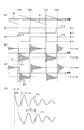
- FIG. 24 is a diagram showing a timing chart during the switching operation according to the conventional example, and shows only the operation of the high-side switching element group Q91 in FIG.
- FIG. 24A shows the voltage fluctuation between terminals of the switching element Q91a
- FIG. 24B shows the voltage fluctuation between terminals of the switching element Q91b
- FIG. 24C is an enlarged view of the portion (D).
- the on-off switching operation of the switching elements Q91a and Q91b causes the terminal voltage of each switching element to transition between a high level and a low level.
- the state transition is not simply performed between the high level and the low level.
- ringing voltages as indicated by Vra and Vrb are generated between the terminals of the switching elements Q91a and Q91b, respectively. Yes.
- This ringing voltage is resonance caused by the parasitic inductance component L and the parasitic capacitance component C included in the circuit constituting the three-phase inverter. As a result of intensive studies by the present inventors, it has been found that this ringing voltage is one of the causes of switching noise.
- the present invention has been made in view of the above problems, and an object thereof is to provide a power conversion device capable of efficiently suppressing switching noise.
- a power converter includes a capacitor, a plurality of switching elements connected in parallel to the capacitor, and a controller that individually controls a switching operation in each switching element,
- a closed circuit including any one of the plurality of switching elements and the capacitor is a power conversion device formed for each switching element, and the controller is turned on or off performed by each switching element.
- a ringing voltage generated in each closed circuit by a switching operation and having a frequency defined by an inductance included in each closed circuit and an output capacity of a switching element included in the closed circuit is generated in each of the plurality of closed circuits. So that at least two closed circuits cancel each other , Shifted from each other the timing of the switching operation in said at least two closed circuit of the switching element.
- the ringing voltage generated in the closed circuit including the capacitor and the switching element by the switching operation performed in each switching element is canceled out between the at least two closed circuits.
- “so that the ringing voltage is canceled” includes not only the case where the ringing voltage is completely canceled but also the case where the ringing voltage is partially canceled. Even when a part of the ringing voltage is canceled out, it is possible to suppress the switching noise as compared with the conventional case.
- Patent Document 1 it is conceivable to take a technique of suppressing switching noise by adding a noise canceling circuit to the power converter.
- this method can suppress the switching noise generated by the switching operation from being conducted from the closed circuit to the power supply side, the switching noise itself can be suppressed in the closed circuit. I can't. Therefore, it is effective for conduction noise transmitted to the power supply side via parasitic capacitance and wiring included in the circuit that constitutes the system, but there is a problem that the suppression effect is low for radiation noise radiated to the space. is there.
- switching noise can be suppressed in the closed circuit that is the source of the switching noise.
- it is possible to obtain an effect of suppressing radiation noise radiated to the space outside the power conversion device as well as conduction noise transmitted to the power supply via the parasitic capacitance and wiring in the power conversion device.
- FIG. 3 is a circuit diagram illustrating an example of a configuration of a phase shift unit according to the first embodiment. It is a figure which shows the timing chart which concerns on 1st Embodiment. Is a diagram showing an equivalent circuit model for calculating the frequency f r. It is a figure for demonstrating the effect which concerns on 1st Embodiment. It is a figure which shows the whole structure of 100 A of load drive systems provided with the power converter device which concerns on the modification of 1st Embodiment.
- FIG. 1 is a diagram illustrating an overall configuration of a load driving system 100 including a power conversion device according to the first embodiment.
- a configuration using a three-phase AC motor (hereinafter referred to as a motor) as a load will be described.
- the load drive system 100 includes a DC power source DC, a power converter 113, and a motor 104.
- DC power supply DC is a DC power supply obtained by rectifying a power supply system, or a DC power supply of a battery type (typically a secondary battery such as nickel metal hydride or lithium ion).
- a battery type typically a secondary battery such as nickel metal hydride or lithium ion.
- the power converter 113 includes a voltage detection unit 101, a current detection unit 103, a three-phase inverter 102, and a controller 105.
- the power conversion device 113 converts the DC power supplied from the DC power source DC into U-phase, V-phase, and W-phase three-phase AC power whose phases are 120 ° and shifted by 2 ⁇ / 3 radians in electrical angle. supplying three-phase AC power to the motor 104.
- the motor 104 is a three-phase AC motor composed of three-phase windings that are supplied with three-phase AC power.
- the voltage detection unit 101 detects the voltage of the DC power supply DC, that is, the voltage input to the three-phase inverter 102.
- the current detection unit 103 detects an input current to the motor 104, that is, a current output from the three-phase inverter 102.
- the capacitor (smoothing capacitor) 111 is provided to suppress voltage fluctuation in the power conversion device 113.
- the three-phase inverter 102 forms a three-phase bridge, and includes a U-phase arm 112u, a V-phase arm 112v, and a W-phase arm 112w.
- the configuration of the arm for each phase is the same as that of the three-phase inverter 902 in FIG.
- the switching elements Q11a and Q11b the switching elements that are connected in parallel are configured with switching elements having the same specifications such as withstand voltage and current capacity.
- the switching elements Q11a to Q16a and Q11b to Q16b include insulated gate bipolar transistors (Insulated Gate Bipolar Transistors: hereinafter referred to as IGBTs) and metal-oxide-semiconductor field effect transistors (Metal-Oxide-SemiconductorEffectTranstor: Hereinafter, a power semiconductor element represented by MOSFET is applied.
- a diode for flowing a current from the emitter side (source side) to the collector side (drain side) is connected between the collector and emitter (or between the drain and source) of the switching elements Q11a, Q11b, Q12a, and Q12b.
- MOSFET Metal-Oxide-SemiconductorEffectTranstor
- a closed circuit including any one of the switching elements Q11a to Q16a and Q11b to Q16b and the capacitor 111 is formed for each switching element.
- one closed circuit includes a switching element Q11a and a capacitor 111, and such a closed circuit is formed in the power conversion device 113 by the number of switching elements (12).
- Controller 105 The controller 105 individually controls the switching operations of the switching elements Q11a to Q16a and Q11b to Q16b included in the three-phase inverter 102.
- the controller 105 generates a pulse width modulation signal (hereinafter referred to as a PWM signal) that is a command signal to the gate drive circuit GD.
- a PWM signal a pulse width modulation signal
- the controller 105 By outputting this PWM signal to the gate terminals of the switching elements Q11a to Q16a and Q11b to Q16b via the gate drive circuit GD, each of the switching elements is individually controlled.
- the controller 105 includes a carrier signal generation unit 106, a PWM signal generation unit 107, a phase shift unit 108, a current command unit 109, and a current control unit 110.
- the carrier signal generator 106 is a carrier signal Cr that is a sawtooth voltage having a frequency of several tens of kHz (for example, the voltage gradually decreases from the first level to the second level over a predetermined time, and then from the second level to the first level). Waveform generated by repeating the reset), and outputs this to the PWM signal generator 107 at the next stage.
- the current command unit 109 outputs a current command for driving and controlling the motor 104.
- the value of the current command is set according to the target operation of the motor 104, and this command includes information on the amplitude and frequency of the control command signal to be generated by the current control unit 110 in the next stage. include.
- the current control unit 110 generates a control command signal having a sine waveform based on the current command from the current command unit 109.
- the control command signal is received as an appropriate sine waveform in response to a feedback signal from the current detection unit 103.
- the U-phase control command signal is indicated by Du
- the V-phase control command signal is indicated by Dv
- the W-phase control command signal is indicated by Dw.
- the current command unit 109 and the current control unit 110 constitute a control command signal generation unit.
- the PWM signal generation unit 107 compares the input carrier signal Cr with the U-phase control command signal Du, generates a PWM signal Pu as a comparison result, and outputs it to the phase shift unit 108 at the next stage. Similarly, carrier signal Cr and V-phase control command signal Dv, carrier signal Cr and W-phase control command signal Dw are compared, and PWM signals Pv and Pw, which are the comparison results, are generated and output to phase shift unit 108. .
- the phase shift unit 108 generates a PWM signal for each switching element based on the input PWM signals Pu, Pv, and Pw, and outputs the PWM signal to the gate drive circuit GD at the next stage.
- the phase shift unit 108 generates the PWM signal Pua by shifting the PWM signal Pu by the first phase angle, and also describes the PWM signal Pu as the second.
- the PWM signal Pub is generated by shifting by the phase angle. The second phase angle is delayed by a predetermined phase difference with respect to the first phase angle.
- the PWM signal Pua is output as a PWM signal for the switching element Q11a
- the PWM signal Pub is output as a PWM signal for the switching element Q11b.
- the phase shift unit 108 changes only the phase difference between the PWM signals Pua and Pub.
- the phase shift unit 108 performs the same phase shift on the PWM signal output to the switching elements (for example, Q14a and Q14b) connected in parallel in the other switching element groups.
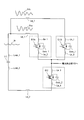
- FIG. 2 is a circuit diagram showing an example of the configuration of the phase shift unit 108, and shows the PWM signal generation unit 107 and the phase shift unit 108 taken out.
- the U-phase phase shift unit 108u includes resistors R1 and R2, capacitors C1 and C2, and Schmitt triggers Sc1 and Sc2.
- the first phase angle described above is determined by the product of R1 and C1
- the second phase angle is determined by the product of R2 and C2.
- a PWM signal Pub that is delayed by a predetermined phase difference with respect to the PWM signal Pua output from the Schmitt trigger Sc1 is generated.
- the timing of the switching operation is shifted between the switching elements Q11a and Q11b. be able to.
- the amount of deviation of the switching operation timing at this time is set to such an amount that the ringing voltage generated between the terminals of the switching element Q11a and the ringing voltage generated between the terminals of the switching element Q11b cancel each other. .
- a specific method for setting the deviation amount and its effect will be described in the next section.
- FIG. 3 is a diagram showing a timing chart according to the first embodiment. Here, only the high-side switching element group Q11 of the U-phase arm 112u will be described.
- FIG. 3A is a diagram illustrating voltage waveforms of the sawtooth carrier signal Cr and the U-phase control command signal Du input to the PWM signal generation unit 107.
- the U-phase control command signal Du has a sinusoidal waveform
- FIG. 3A is an enlarged view of a minute time, and is illustrated here as a voltage hardly changing.
- FIG. 3B shows a voltage waveform of the PWM signal Pua output from the phase shift unit 108
- FIG. 3C shows a voltage waveform of the PWM signal Pub output from the phase shift unit 108.
- the PWM signal Pub is delayed by ⁇ [sec] with respect to the PWM signal Pua, and this ⁇ corresponds to the above-described predetermined phase difference.
- R1, R2, C1, and C2 are set so that the first phase angle (product of R1 and C1) is negligible and the second phase angle (product of R2 and C2) corresponds to ⁇ .
- Such a configuration can be realized by setting a value.
- FIG. 3D shows the voltage fluctuation between the terminals of the switching element Q11a
- FIG. 3E shows the voltage fluctuation between the terminals of the switching element Q11b
- FIG. 3F shows the voltage fluctuation between FIGS.
- FIG. 3A the carrier signal Cr and the U-phase control command signal Du intersect, and the PWM signal Pua shown in FIG. 3B transitions from on to off.
- the switching element Q11a is switched from on to off, and the voltage between the terminals of the switching element Q11a transitions from a high level to a low level (FIG. 3 (d)).
- FIG. 3D since there is a large current change in the switching element Q11a in a short time, as shown in FIG. 3D, a ringing voltage Vra that is high-frequency vibration is generated between the terminals of the switching element Q11a.
- the ringing voltage generated in the switching element is one of the causes of the switching noise. Therefore, switching noise can be suppressed by suppressing the generation of the ringing voltage.
- the ringing voltage is resonance caused by the parasitic inductance component L and the parasitic capacitance component C included in the circuit constituting the three-phase inverter.
- the frequency f of the ringing voltage is determined by Equation 1.
- the PWM signal Pub shown in FIG. 3C transitions from on to off with a delay of ⁇ [sec] from time (1).
- the switching element Q11b is switched from on to off, and the voltage between the terminals of the switching element Q11b transitions from a high level to a low level (FIG. 3 (e)).
- the switching element Q11b similarly to the switching element Q11a, the switching element Q11b also has a large current change in a short time.
- the ringing voltage Vrb which is high-frequency vibration, is generated between the terminals of the switching element Q11b. appear.
- the switching elements Q11a and Q11b are configured by switching elements having the same specifications such as withstand voltage and current capacity, and the parasitic inductance L included in the switching element Q11b and The parasitic capacitance component C is the same as that included in the switching element Q11a. That is, the frequency f r of the ringing voltage Vrb generated between the frequencies f r and the switching element Q11b ringing voltage Vra terminal generated between the switching elements Q11a terminals are equivalent.
- the phase difference ⁇ is equivalent to a half cycle of ringing voltage Vra.
- ⁇ is defined by the number 2 using the frequency f r of the ringing voltage Vra.
- the frequency f r of the ringing voltage Vra is roughly the switching elements included in the inductance and the closed circuit of the closed circuit including the switching element Q11a and a capacitor 111 (closed circuit that is the source of ringing voltage Vra) It is defined by the output capacity of Q11a. The method of calculating the frequency f r of the ringing voltage Vra will be described later in detail.
- the ringing voltage Vra and the ringing voltage Vrb have a relationship in which the phases are inverted as shown in FIG. By doing so, the ringing voltages Vra and Vrb generated by the switching operation from the on to the off performed by the switching elements Q11a and Q11b cancel each other, and as a result, the switching noise generated from these switching elements is suppressed. Is done.
- the time (3) will be described.
- the carrier signal Cr and the U-phase control command signal Du intersect, and the PWM signal Pua shown in FIG. 3B transitions from off to on.
- the switching element Q11a is switched from off to on, and the voltage across the switching element Q11a transitions from low level to high level (FIG. 3 (d)).
- the ringing voltage Vra is generated between the terminals of the switching element Q11a.
- the PWM signal Pub shown in FIG. 3 (c) transitions from OFF to ON with a delay of ⁇ [sec] from time (3).
- the switching element Q11b is switched from OFF to ON, and the voltage between the terminals of the switching element Q11b transitions from low level to high level (FIG. 3 (e)).
- the ringing voltage Vrb is generated between the terminals of the switching element Q11b.
- both the ringing voltage generated in accordance with the state transition from the on state to the off state and the ringing voltage generated in accordance with the state transition from the off state to the on state can be achieved. It is possible to cancel.
- FIG. 4 is a diagram showing an equivalent circuit model for calculating the frequency f r.
- FIG. 4 illustrates only the U-phase arm 112u and the capacitor 111 in FIG.
- the switching elements Q11a and Q11b and the switching elements Q12a and Q12b are respectively connected in parallel in the U-phase arm 112u, the amount of current flowing between the switching elements Q11a and Q11b is substantially the same.
- the amount of current flowing between the switching elements Q12a and Q12b is substantially the same. Therefore, for the sake of simplification, in FIG. 4, it is assumed that the switching element of the U-phase arm 112u is composed of only the switching element Q11a and the switching element Q12a. Therefore, FIG. 4 shows a closed circuit including the switching element Q11a (or switching element Q11b) and the capacitor 111, and a closed circuit including the switching element Q12a (or switching element Q12b) and the capacitor 111.
- the capacitor 111 since the capacitor 111 is set as a sufficiently large capacity when supplying switching energy, the capacitor 111 can be regarded as an ideal voltage source. However, the capacitor 111 has a parasitic inductance component due to wiring connecting the capacitor 111 and other components, and the inductances are set as Lcap_1 and Lcap_2.
- the output capacitance of the switching element Q11 is Coss_1
- the inductances of the wiring included in the switching element Q11 are Lm_1 and Lm_2.
- the output capacitance of the switching element Q12 is Coss_2
- the inductances of the wirings connecting the switching element Q12 and other components are Lm_3 and Lm_4.
- the inductance of the wiring connecting the capacitor 111 and the U-phase arm 112u is set to Lw_1 and Lw_2.
- the inductance of the wiring included in the switching element Q11a is switched to Lm_1 and Lm_2, and the inductance included in the capacitor 111 is switched to Lcap_1 and Lcap_2.
- the inductance of the wiring connecting the element Q11a and the capacitor 111 corresponds to Lm_3, Lm_4, Lw_1, and Lw_2, respectively. Therefore, the inductance of the closed circuit including the switching element Q11a and the capacitor 111 is composed of Lcap_1, Lcap_2, Lw_1, Lw_2, Lm_1, Lm_2, Lm_3, and Lm_4.
- the inductance of the wiring included in switching element Q12a is Lm_3 and Lm_4
- the inductance included in capacitor 111 is Lcap_1 and Lcap_2
- the switching element The inductances of the wiring connecting Q12a and the capacitor 111 correspond to Lm_1, Lm_2, Lw_1, and Lw_2, respectively. Therefore, the inductance of the closed circuit including the switching element Q12a and the capacitor 111 is composed of Lcap_1, Lcap_2, Lw_1, Lw_2, Lm_1, Lm_2, Lm_3, and Lm_4.
- the equivalent circuit model shown in FIG. 4 forms a resonance circuit composed of the parasitic inductance component L and the parasitic capacitance component C.
- Frequency f r of the equivalent circuit model of FIG. 4 can be calculated by applying Equation 1 to the equivalent circuit. Indeed when calculating the frequency f r, (1) Consider the case where the switching element Q11a switching element Q12a is ON off, (2) when the switching element Q11a switching element Q12a ON is two in the case of off .
- the switching operation to turn off the switching element Q11a is a trigger, and a ringing voltage is generated between the terminals of the switching element Q11a.
- the switching element Q12a can be regarded as a simple wiring, more precisely, a resistor due to the on-resistance of the switching element. Therefore, the frequency f r1 of the ringing voltage in the case of (1) is expressed by Equation 3.
- the switching operation to turn off the switching element Q12a is a trigger, and a ringing voltage is generated between the terminals of the switching element Q12a.
- the switching element Q11a can be regarded as a simple wiring, more precisely, a resistor due to the on-resistance of the switching element. Therefore, the frequency f r2 of the ringing voltage in the case of (2) is expressed by Equation 4.
- the frequency f r is not affected by the motor 104 is determined by the capacitor 111 and the U-phase arm 112u. Be calculated each parasitic inductance components such Lm_1 and Lm_2 using an electromagnetic field simulation, etc., it is possible to obtain the frequency f r from the number 5 in the design phase. Further, when the frequency fr is obtained, the phase shift amount ⁇ [sec] of Equation 2 is also obtained. Therefore, it is possible to set the value of the predetermined phase difference ⁇ at the design stage.
- the V-phase arm 112v, W-phase arm 112w is the U-phase arm 112u and specifications are composed of the same components, V-phase arm 112v , the frequency f r of the ringing voltage generated by the switching operation in the W-phase arm 112w is as shown in Equation 5.
- FIG. 5 is a diagram for explaining the effect according to the present embodiment. 5, only the U-phase arm 112u and the capacitor 111 are shown in the same manner as FIG.
- the switching element Q11 is illustrated by distinguishing between the switching element Q11a and the switching element Q11b, but the switching element Q12 is simplified as in FIG.
- the switching elements Q11a and Q11b since the switching elements having the same specifications are used for the switching elements Q11a and Q11b, the output capacitance (Coss_1) of these switching elements and the inductance of the wiring connecting these to other components, etc. (Lm_1, Lm_2) are the same. Further, if the wiring distance connecting capacitor 111 and switching element Q11a is the same as the wiring distance connecting capacitor 111 and switching element Q11b, the inductance of these wirings can be Lw_1. Therefore, the switching elements Q11a, ringing voltage Vra generated between Q11b of terminals, the frequency f r of the Vrb is the same.
- the ringing voltages Vra and Vrb can be canceled in a closed circuit connecting the switching elements Q11a and Q11b and the capacitor 111, and are closed as indicated by Vr in FIG. voltage variations in the circuit is suppressed. Therefore, not only the conduction noise transmitted to the power supply via the parasitic capacitance and wiring in the power converter, but also the effect of suppressing radiation noise radiated to the space outside the power converter can be expected. Further, since the switching noise is suppressed in the closed circuit that is a generation source, it is possible to exert an effect of suppressing both so-called normal mode noise and common mode noise.
- noise suppression components such as an EMI filter and a shield are not used. , suppression of switching noise can be obtained. Even when a noise suppression component is used, a component having a small noise suppression effect is sufficient, and the load drive system 100 does not increase in size.
- the PWM signal generated by the PWM signal generation unit 107 is phase-shifted by the phase shift unit 108 to generate the PWM signal for each switching element.
- a carrier signal for each switching element is generated, and a PWM signal for each switching element is generated based on these signals.
- FIG. 6 is a diagram illustrating an overall configuration of a load drive system 100A including a power conversion device according to a modification of the first embodiment.
- the difference between the configuration shown in FIG. 6 and the first embodiment (FIG. 1) is the configuration of the controller 105A in the power conversion device 113A, mainly the carrier signal generation unit 106A and the PWM signal generation unit 107A.
- the description will be continued focusing on the high-side switching element group Q11 of the U-phase arm 112u.
- the carrier signal generation unit 106A generates sawtooth carrier signals Cra and Crb for generating the PWM signals Pua and Pub for the switching elements Q11a and Q11b, and outputs them to the PWM signal generation unit 107A in the next stage.
- FIG. 7 is a circuit diagram showing an example of the configuration of the carrier signal generation unit 106A according to this modification.
- the pulse signal generation unit generates a pulse signal Pl that is a narrow pulse waveform generated at a constant period, and outputs the pulse signal Pl to the phase shift circuit at the next stage.
- the phase shift circuit generates a pulse signal for each switching element based on the input pulse signal Pl.
- the phase shift circuit shifts the pulse signal Pl by the third phase angle to generate the pulse signal Pl1, and shifts the pulse signal Pl by the fourth phase angle to generate the pulse signal Pl2.
- the fourth phase angle is delayed by ⁇ [sec] with respect to the third phase angle.
- the pulse signal Pl1 is output to the transistor Tr1, and the pulse signal Pl2 is output to the transistor Tr2.
- Transistors Tr1 and Tr2 are turned on for a moment in a constant cycle when pulse signals Pl1 and Pl2 are input. Further, since the pulse signal Pl2 is delayed by ⁇ [sec] relative to the pulse signal Pl1, the timing at which the transistor Tr2 is turned on is also delayed by ⁇ [sec] relative to the transistor Tr1.
- the capacitor C3 is discharged toward the constant current source I, and the voltage of the capacitor C3 drops at a constant speed.
- the capacitor C3 is charged, and the voltage of the capacitor C3 increases instantaneously at a constant period.
- circuit configuration shown in FIG. 7 for example, the circuit configuration disclosed in FIG. 3 of Patent Document 2 can be used.
- PWM signal generation unit 107A (FIG. 6) generates PWM signal Pu for switching element Q11a and PWM signal Pub for switching element Q11b based on carrier signals Cra and Crb.
- the PWM signals Pua and Pub finally output to the switching elements Q11a and Q11b are the same as the PWM signals Pua and Pub (FIGS. 3B and 3C) in the first embodiment.
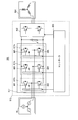
- FIG. 8 is a diagram illustrating a partial configuration of the power conversion device according to the second embodiment, in particular, a three-phase inverter 202 and a phase shift unit 208.
- the three-phase inverter 202 includes a high-side switching element group Q21, Q23, Q25 and a low-side switching that constitute a U-phase arm 212u, a V-phase arm 212v, and a W-phase arm 212w.
- a high-side switching element group Q21, Q23, Q25 and a low-side switching that constitute a U-phase arm 212u, a V-phase arm 212v, and a W-phase arm 212w.
- a plurality of switching elements are connected in parallel. However, the number of switching elements connected in parallel is different from that of the first embodiment.
- the high-side switching element group Q21 includes three switching elements Q21a, Q21b, and Q21c connected in parallel
- the low-side switching element group Q22 includes a switching element.
- Three switching elements Q22a, Q22b, and Q22c are connected in parallel.
- the high-side switching element group Q23 of the V-phase arm 212v has three switching elements Q23a, Q23b, and Q23c
- the low-side switching element group Q24 has switching elements Q24a and Q24b. , Q24c are connected in parallel.
- the high-side switching element group Q25 includes three switching elements Q25a, Q25b, and Q25c
- the low-side switching element group Q26 includes three switching elements Q26a, Q26b, and Q26c. Each of the switching elements is connected in parallel.
- the phase shift unit 208 has substantially the same configuration as that of the phase shift unit 108 according to the first embodiment, and the configuration not particularly shown in FIG. 8 is also substantially the same as that of the first embodiment.
- the description will focus on the high-side switching element group Q21 of the U-phase arm 212u.
- the phase shift unit 208 is based on the PWM signal Pu input from the PWM signal generation unit (not shown), the PWM signal Pua for the switching element Q21a, the PWM signal Pub for the switching element Q21b, and the PWM signal for the switching element Q21c.
- Puc is generated and output to the gate drive circuit GD at the next stage.
- the phase shift unit 208 shifts the PWM signal Pu by the first phase angle to generate the PWM signal Pua, shifts the PWM signal Pu by the second phase angle to generate the PWM signal Pub, and generates the PWM signal Pu.
- the PWM signal Puc is generated by shifting by the third phase angle.
- the second phase angle is delayed by ⁇ [sec] (same as described in the first embodiment) with respect to the first phase angle
- the third phase angle is equal to the second phase angle. It is delayed by ⁇ [sec] with respect to the phase angle.
- the timing of the switching operation can be shifted between the switching elements Q21a, Q21b, and Q21c.
- FIG. 9 is a diagram illustrating a timing chart according to the second embodiment. Here, only the high-side switching element group Q21 of the U-phase arm 212u will be described.
- FIG. 9A is a diagram illustrating voltage waveforms of the sawtooth carrier signal Cr and the U-phase control command signal Du input to the PWM signal generation unit according to the present embodiment. These voltage waveforms are the first waveform. This is the same as that according to the embodiment (FIG. 3A).
- FIG. 9B shows the voltage waveform of the PWM signal Pua output from the phase shift unit 208
- FIG. 9C shows the voltage waveform of the PWM signal Pub
- FIG. 9D shows the voltage waveform of the PWM signal Puc. Show.
- the PWM signal Puc is 2 ⁇ [sec] with respect to the PWM signal Pua ( ⁇ is the same as that described in the first embodiment). It is delayed by ⁇ [sec] with respect to the PWM signal Pub.
- FIG. 9E shows the voltage fluctuation between the terminals of the switching element Q21a
- FIG. 9F shows the voltage fluctuation between the terminals of the switching element Q21b
- FIG. 9G shows the voltage between the terminals of the switching element Q21c.
- FIG. 9 (h) shows an enlarged view around (B) shown in FIGS. 9 (e), (f), and (g).
- time (1) in FIG. 9 will be described.
- the carrier signal Cr and the U-phase control command signal Du cross each other, and the PWM signal Pua shown in FIG. 9B transitions from on to off.
- the switching element Q21a is switched from on to off, and the voltage between the terminals of the switching element Q21a transitions from the high level to the low level (FIG. 9 (e)).
- a ringing voltage Vra is generated between the terminals of the switching element Q21a.
- FIG. 9 (2) a description will be given time in FIG. 9 (2).
- the PWM signal Pub shown in FIG. 9C transitions from on to off with a delay of ⁇ [sec] from time (1).
- the switching element Q21b is switched from on to off, and the voltage between the terminals of the switching element Q21b transitions from a high level to a low level (FIG. 9 (f)).
- a ringing voltage Vrb is generated between the terminals of the switching element Q21b.
- the ringing voltage Vra and the ringing voltage Vrb have a relationship in which the phases are inverted.
- the ringing voltages Vra and Vrb generated by the switching operation from on to off performed by the switching elements Q21a and Q21b cancel each other, and as a result, switching noise generated from these switching elements is suppressed. Is done.
- the PWM signal Puc shown in FIG. 9D transitions from on to off with a delay of ⁇ [sec] from time (2) and 2 ⁇ [sec] from time (1).
- the switching element Q21c is switched from on to off, and the voltage between the terminals of the switching element Q21c transitions from the high level to the low level (FIG. 9 (g)).
- a ringing voltage Vrc is generated between the terminals of the switching element Q21c. This ringing voltage Vrc remains as it is without canceling out other ringing voltages.
- the time (4) will be described.
- the carrier signal Cr and the U-phase control command signal Du intersect, and the PWM signal Pua shown in FIG. 9B transitions from OFF to ON.
- the switching element Q21a is switched from OFF to ON, and the voltage between the terminals of the switching element Q21a transitions from the low level to the high level ((e) in FIG. 9).
- the ringing voltage Vra is generated between the terminals of the switching element Q21a.
- the PWM signal Pub shown in FIG. 9 (c) transitions from OFF to ON with a delay of ⁇ [sec] from time (4).
- the switching element Q21b is switched from off to on, and the voltage across the terminals of the switching element Q21b transitions from low level to high level (FIG. 9 (f)).
- the ringing voltage Vrb is generated between the terminals of the switching element Q21b.
- the PWM signal Puc shown in FIG. 9D transitions from OFF to ON with a delay of ⁇ [sec] from time (5) and 2 ⁇ [sec] from time (4).
- the switching element Q21c is switched from OFF to ON, and the voltage between the terminals of the switching element Q21c transitions from low level to high level (FIG. 9 (g)).
- the ringing voltage Vrc is generated between the terminals of the switching element Q21c. This ringing voltage Vrc remains as it is without canceling out other ringing voltages.
- the ringing voltages Vra and Vrb are generated when the switching element is generated along with the state transition from on to off, and with the state transition from off to on. It is possible to cancel both of the occurrences.
- the switching noise suppression effect is inferior to that of the first embodiment.
- the switching noise can be suppressed to about one third as compared with the conventional case where three switching elements are operated in synchronization.
- phase shift unit Similar to the phase shift unit 208 according to the second embodiment, the phase shift unit according to the present modification generates the PWM signals Pua, Pub, and Puc. In the second embodiment, a predetermined phase difference is generated. Is ⁇ [sec], in the present modification, this predetermined phase difference is ⁇ [sec]. ⁇ is defined by the number 6 using the frequency f r of the ringing voltage generated in the switching element.
- phase difference ⁇ corresponds to one-third period of the ringing voltage.
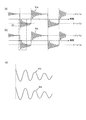
- FIG. 10 is a diagram illustrating a timing chart according to the present modification.
- FIGS. 10A, 10B, and 10C illustrate ringing voltages Vra, Vrb, and Vrc generated in the switching elements Q21a, Q21b, and Q21c, respectively. it is an enlarged view of the waveform.
- the phase difference ⁇ By setting the phase difference ⁇ to a value corresponding to one-third period of the ringing voltage, when the ringing voltages Vra, Vrb, and Vrc are accurate sine waves, the sum of these ringing voltages is zero. And the ringing voltages cancel each other.
- FIG. 11 is a diagram illustrating an overall configuration of a load driving system 300 including the power conversion device according to the third embodiment.
- the load driving system 300 includes a DC power source DC, a power conversion device 313, and a motor 304.
- the direct-current power source DC and the motor 304 have the same configuration as the direct-current power source DC and the motor 104 in the first embodiment, respectively, but the configuration of the power conversion device 313 is different from that of the power conversion device 113 in the first embodiment.
- the power conversion device 313 includes a voltage detection unit 301, a current detection unit 303, a three-phase inverter 302, and a controller 305.
- the voltage detection unit 301 and the current detection unit 303 have the same configuration as the voltage detection unit 101 and the current detection unit 103 in the first embodiment, respectively.
- the three-phase inverter 302 and the controller 305 are different in configuration from the three-phase inverter 102 and the controller 105 in the first embodiment.
- the three-phase inverter 302 includes a U-phase arm 312u, a V-phase arm 312v, and a W-phase arm 312w.
- the U-phase arm 312u further includes a high-side switching element Q31 and a low-side switching element Q32 connected in series.
- the high-side switching element Q31 and the low-side switching element Q32 of this embodiment are each composed of a single switching element.
- the V-phase arm 312v and the W-phase arm 312w have the same configuration as the U-phase arm 312u.
- the switching elements Q31 to Q36 are constituted by a common switching element.
- a closed circuit including any one of the U-phase arm 312u, the V-phase arm 312v, and the W-phase arm 312w and the capacitor 311 is formed for each arm. That is, one closed circuit includes a U-phase arm 312u and a capacitor 311. Such a closed circuit is formed in the power conversion device 313 by the number of arms (three).
- the description will focus on the high-side switching elements Q31, Q33, and Q35.
- the controller 305 includes a carrier signal generation unit 306, a PWM signal generation unit 307, a phase shift unit 308, a current command unit 309, and a current control unit 310.
- the carrier signal generation unit 306, the PWM signal generation unit 307, the current command unit 309, and the current control unit 310 are the carrier signal generation unit 106, the PWM signal generation unit 107, the current command unit 109, and the current control, respectively, in the first embodiment. parts 110 have the same configuration as.
- the phase shift unit 308 is different in configuration from the phase shift unit 108 in the first embodiment.
- the phase shift unit 308 includes a PWM signal Pu ′ output to the high side switching element Q31 based on the input PWM signals Pu, Pv, and Pw, a PWM signal Pv ′ output to the high side switching element Q33, and the high side switching element.
- the PWM signal Pw ′ output to Q35 is generated and output to the next stage gate drive circuit GD.
- the phase shift unit 308 shifts the PWM signal Pu by the first phase angle to generate the PWM signal Pu ′, shifts the PWM signal Pv by the second phase angle to generate the PWM signal Pv ′, and generates the PWM signal.
- the PWM signal Pw ′ is generated by shifting Pw by the third phase angle.
- the second phase angle is delayed by ⁇ [sec] (same as described in the first embodiment) with respect to the first phase angle
- the third phase angle is equal to the second phase angle. It is delayed by ⁇ [sec] with respect to the phase angle.
- the frequency of the ringing voltage generated in the closed circuit including the U-phase arm 312u and the capacitor 311 by the switching operation of the switching element Q31 of the U-phase arm 312u is included in the inductance included in the closed circuit and the closed circuit. It is defined by the output capacity of the switching element Q31 constituting the arm.
- FIG. 4 shows a closed circuit including U-phase arm 312u and capacitor 311. Therefore, the method for calculating the frequency fr described in FIG. 4 can also be applied to this embodiment.
- the switching element Q31 and the capacitor 311 are connected to the inductance of the wiring included in the switching element Q31 with Lm_1 and Lm_2, and the inductance included in the capacitor 311 with Lcap_1 and Lcap_2.
- the wiring inductances correspond to Lm_3, Lm_4, Lw_1, and Lw_2, respectively. Therefore, the inductance included in this closed circuit is composed of Lcap_1, Lcap_2, Lw_1, Lw_2, Lm_1, Lm_2, Lm_3, and Lm_4.
- FIG. 12A is a diagram illustrating voltage waveforms of the sawtooth carrier signal Cr, the U-phase control command signal Du, the V-phase control command signal Dv, and the W-phase control command signal Dw input to the PWM signal generation unit 307.
- the carrier signal Cr has a sawtooth waveform similar to that in the first embodiment.
- the U-phase control command signal Du, V-phase control command signal Dv, and W-phase control command signal Dw are 120 ° out of phase and 2 ⁇ / 3 radians at an electrical angle.
- FIG. 12B shows a voltage waveform of the PWM signal Pu ′ output from the phase shift unit 308.
- FIG. 12C shows the voltage waveform (dotted line) of the PWM signal Pv input to the phase shift unit 308 and the PWM signal Pv ′ (solid line) output from the phase shift unit 308, respectively.
- the PWM signal Pv ′ is delayed by ⁇ [sec] with respect to the PWM signal Pv.
- FIG. 12D shows the voltage waveform (dotted line) of the PWM signal Pw input to the phase shift unit 308 and the PWM signal Pw ′ (solid line) output from the phase shift unit 308, respectively.
- the PWM signal Pw ′ is delayed by 2 ⁇ [sec] with respect to the PWM signal Pw.
- FIG. 12 (e) shows the voltage fluctuation between the terminals of the high-side switching element Q31
- FIG. 12 (f) shows the voltage fluctuation between the terminals of the high-side switching element Q33
- FIG. 12 (g) shows the high-side switching element.
- FIG. 12 (h) shows an enlarged view of the vicinity of (C) shown in FIGS. 12 (e), 12 (f), and 12 (g).
- FIG. 12A the carrier signal Cr and the U-phase control command signal Du cross each other, and the PWM signal Pu ′ shown in FIG. 12B transitions from on to off.
- the high-side switching element Q31 is switched from on to off, and the voltage between the terminals of the high-side switching element Q31 transitions from the high level to the low level (FIG. 12 (e)).
- a ringing voltage Vru is generated between the terminals of the high-side switching element Q31.
- the control command signals Dv and Dw also intersect with the carrier signal Cr at time (1), and thus are output from the PWM signal generation unit 307. Also in the PWM signals Pv and Pw, the state transition from on to off occurs. If the PWM signals Pv and Pw are output to the gate terminals of the high-side switching elements Q33 and Q35 without being phase-shifted by the phase shift unit 308, the high-side switching elements Q31, Q33, and Q35 are simultaneously switched. Will be done. As a result, ringing voltages having the same phase are generated from the high-side switching elements Q31, Q33, and Q35, so that switching noise is superimposed in triplicate. Therefore, in this embodiment, the phase shift unit 308 is configured to shift the phases of the PWM signals Pv and Pw so that the switching operation is not performed at the same time.
- the PWM signal Pv ′ output from the phase shift unit 308 has a phase difference of ⁇ [sec] with respect to the PWM signal Pv (FIG. 12C).
- ⁇ is defined by Equation 2 in the first embodiment.
- the frequency f r in equation 2 is the frequency of the ringing voltage Vru occurring high-side switching element Q31.
- the switching elements Q31 to Q36 are composed of switching elements having the same specifications such as withstand voltage and current capacity, the frequency of the ringing voltage generated in each switching element is the same value.
- the PWM signal Pv ′ shown in FIG. 12 (c) is changed from on to off with a delay of ⁇ [sec] from time (1).
- the high-side switching element Q33 is switched from on to off, and the voltage between the terminals of the high-side switching element Q33 transitions from the high level to the low level (FIG. 12 (f)).
- a ringing voltage Vrv is generated between the terminals of the high-side switching element Q33.
- the ringing voltage Vru and the ringing voltage Vrv have a relationship in which the phases are inverted.
- the ringing voltages Vru and Vrv generated in association with the switching operation from on to off performed by the high-side switching elements Q31 and Q33 are canceled out, and as a result, switching noise generated from these switching elements. Is suppressed.
- time (3) in FIG. 12 will be described.
- the PWM signal Pw ′ shown in FIG. 12 (d) is shifted from on to off with a delay of 2 ⁇ [sec] from time (1).
- the high-side switching element Q35 is switched from on to off, and the voltage between the terminals of the high-side switching element Q35 transitions from the high level to the low level (FIG. 12 (g)).
- a ringing voltage Vrw is generated between the terminals of the high-side switching element Q35.
- This ringing voltage Vrw remains as it is without canceling out other ringing voltages.
- the ringing voltages Vru and Vrv can be canceled with each other when the switching element is generated with the state transition from on to off.
- the switching noise suppression effect is inferior compared with the first embodiment.
- the switching noise is suppressed to about one third as compared with the case where all the switching elements of the U phase, the V phase, and the W phase are simultaneously switched. Is possible.
- the carrier signal is set to a predetermined time, such as a sawtooth wave, for example. It is preferable to use a carrier signal that repeats reset from the second level to the first level after transition from the first level to the second level.
- a carrier signal that repeats reset from the second level to the first level after transition from the first level to the second level.
- the time at which the switching operation is performed simultaneously occurs periodically corresponding to the timing at which the carrier signal is reset, and does not vary with the duty ratio.
- the timing of the switching operation in the switching element of each phase is controlled by using this time as a phase shift reference. It is possible.
- the switching element cancels both the ringing voltage generated in accordance with the state transition from on to off and the ringing voltage generated in accordance with the state transition from off to on. It was possible to do.
- the ringing voltage that can be canceled is limited to either one. This is because, as shown in FIGS. 12B to 12D, the timing at which the carrier signal and the control command signal intersect in the period in which the carrier signal transitions from the first level to the second level over a predetermined time. This is because it varies depending on the duty ratio. Therefore, it is difficult to use the timing at which the carrier signal and the control command signal intersect as the phase shift reference. However, since either one of the ringing voltages can be canceled out, the noise level can be suppressed to about half compared to the case where the PWM signal for each phase is not phase-shifted.
- a carrier signal for each phase in which a predetermined phase difference is provided between the phases is generated in advance, and each phase is based on the carrier signals. It is also possible to adopt a configuration for generating a PWM signal for use.
- the verification of the switching noise suppression principle according to the present embodiment was specifically performed using the circuit shown in FIG.
- the principle verification circuit shown in FIG. 13 is based on the circuit configuration shown in FIG. 11, and the same components as those shown in FIG.
- a pulse signal is sent from the pulse generator 321 to the gate terminals of the high-side switching elements Q31 and Q33.
- the high-side switching elements Q31 and Q33 perform a switching operation.
- the pulse signal output from the pulse generator 321 has a time difference between the high-side switching elements Q31 and Q33, and the timing of the switching operation is thereby shifted.
- a load 320 is connected to the U-phase arm and the V-phase arm.
- FIG. 14 (a) is a result of assuming the switching operation of the present embodiment
- FIG. 14 (b) is a result of a comparative example.
- the voltage fluctuation between the terminals of the low side switching element Q32 is indicated by a solid line
- the voltage fluctuation between the terminals of the low side switching element Q34 is indicated by a dotted line.
- the time difference between the pulse signals input to the high-side switching elements Q31 and Q33 is ⁇ [sec], and the phase of the ringing voltage is inverted with respect to each other. Yes.
- the time difference between the input pulse signals is substantially zero, and the phase of the ringing voltage is substantially the same.
- a pseudo power supply network (LISN) 318 (FIG. 13) is connected between the DC power supply DC and the three-phase inverter, and voltage fluctuations as shown in FIG. 14 occur between the terminals of the low-side switching elements Q32 and Q34.
- the noise spectrum was measured by the spectrum analyzer 319, and the result is shown in FIG.
- the solid line in FIG. 15 is the result in the present embodiment (corresponding to FIG. 14A), and the dotted line is the result in the comparative example (corresponding to FIG. 14B).
- the switching elements with which the ringing voltages are canceled are switching elements of different phases. Therefore, the PWM signals input to these switching elements are generated based on control command signals having different phases.
- the switching elements that cancel out the ringing voltages are switching elements in the same phase. Therefore, the PWM signal input to these switching elements is generated based on the same control command signal. Therefore, as in the case of the first and second embodiments and the modifications thereof, the embodiment in which the ringing voltages are canceled out between the switching elements in the same phase achieves more accurate noise suppression. Is possible.
- the phase shift unit Similar to the phase shift unit 308 according to the third embodiment, the phase shift unit according to the present modification generates the PWM signals Pu ′, Pv ′, and Pw ′.
- the phase shift unit is predetermined.
- the predetermined phase difference is ⁇ [sec] in the present modification.
- the ⁇ is defined by the number 6 using the frequency f r of the ringing voltage in the same manner as in the modification of the second embodiment, generated in the switching element.
- the frequency f r in equation 6 is the frequency of the ringing voltage Vru occurring high-side switching element Q31.
- this phase difference ⁇ corresponds to one-third period of the ringing voltage.
- FIG. 16 is a diagram illustrating a timing chart according to the present modification.
- FIGS. 16A, 16B, and 16C are ringing voltages Vru and Vrv generated in the high-side switching elements Q31, Q33, and Q35, respectively. , Vrw waveform enlarged view.
- the phase difference ⁇ By setting the phase difference ⁇ to a value corresponding to one third of the ringing voltage, when the ringing voltages Vru, Vrv, and Vrw are accurate sine waves, the sum of these ringing voltages is zero. And the ringing voltages cancel each other.
- FIG. 17 is a diagram illustrating an overall configuration of a load driving system 400 including a power conversion device according to the fourth embodiment. A fourth embodiment will be described with reference to FIG.
- the load drive system 400 includes a DC power source DC, a power conversion device 413, and a motor 404.
- the DC power source DC and the motor 404 have the same configuration as the DC power source DC and the motor 304 in the third embodiment (FIG. 11), respectively, but the power conversion device 413 is the same as the power conversion device 313 in the third embodiment. The configuration is different.
- the power converter 413 includes a voltage detection unit 401, a current detection unit 403, a three-phase inverter 402, and a controller 405.
- the voltage detection unit 401 and the controller 405 are different in configuration from the voltage detection unit 301 and the controller 305 in the third embodiment.
- the controller 405 includes a carrier signal generation unit 406, a PWM signal generation unit 407, a phase shift unit 408, a current command unit 409, and a current control unit 410.
- the carrier signal generation unit 406, the PWM signal generation unit 407, the current command unit 409, and the current control unit 410 are respectively the carrier signal generation unit 306, the PWM signal generation unit 307, the current command unit 309, and the current control in the third embodiment.
- the configuration is the same as that of the unit 310.
- the phase shift unit 408 is different in configuration from the phase shift unit 308 in the third embodiment.
- the difference between the load driving system 400 according to the present embodiment and the third embodiment is that the voltage value of the DC power source DC detected by the voltage detection unit 401 is added as an input to the phase shift unit 408.
- the frequency of the ringing voltage is determined by the output capacity C of the switching element from Equation 1, but it is known that the output capacity of the switching element decreases as the voltage between the terminals of the switching element increases. Therefore, the frequency of the ringing voltage increases as the power supply voltage value increases as noise based on the ringing voltage is conducted from the three-phase inverter 402 to the DC power supply DC side. Therefore, in order to obtain a good noise suppression effect in a system in which the power supply voltage varies greatly, it is necessary to make the set value of the phase difference in the phase shift unit variable.
- the set value of the phase difference provided in the phase shift unit 408 is made variable according to the power supply voltage value detected by the voltage detection unit 401. This can be performed by a method in which a set value of a phase difference corresponding to the power supply voltage value detected by the voltage detection unit 401 is prepared as a database in advance.
- the phase shift unit 408 obtains a feedback signal based on the power supply voltage value detected by the voltage detection unit 401, reads a set value of a phase difference corresponding to the signal from the database, and performs a phase shift operation.
- FIG. 18 is a diagram illustrating an overall configuration of a load driving system 500 including a power conversion device according to the fifth embodiment. The fifth embodiment will be described with reference to FIG.
- the load drive system 500 includes a DC power source DC, a power converter 513, and a motor 504.
- the direct current power source DC and the motor 504 have the same configuration as the direct current power source DC and the motor 404 in the fourth embodiment (FIG. 17), respectively, but the power conversion device 513 is the same as the power conversion device 413 in the fourth embodiment. The configuration is different.
- the power converter 513 includes current detectors 501 and 503, a three-phase inverter 502, and a controller 505.
- the current detection unit 503 and the three-phase inverter 502 have the same configuration as the current detection unit 403 and the three-phase inverter 402 in the fourth embodiment, respectively.
- the controller 505 has a different configuration from the controller 405 in the fourth embodiment, and the current detection unit 501 has a configuration that does not exist in the fourth embodiment.
- the controller 505 includes a carrier signal generation unit 506, a PWM signal generation unit 507, a phase shift unit 508, a current command unit 509, and a current control unit 510.
- the carrier signal generation unit 506, the PWM signal generation unit 507, the current command unit 509, and the current control unit 510 are respectively the carrier signal generation unit 406, the PWM signal generation unit 407, the current command unit 409, and the current control in the fourth embodiment.
- the configuration is the same as that of the unit 410.
- the phase shift unit 508 is different in configuration from the phase shift unit 408 in the fourth embodiment.
- the difference between the load driving system 500 according to the present embodiment and the fourth embodiment is that the current value of the DC power source DC detected by the current detection unit 501 is input to the phase shift unit 508.
- Current detecting section 501 is provided with a high-pass filter, for detecting a ringing voltage component that conducts to the DC power supply DC side from the three-phase inverter 502.
- the frequency of the ringing voltage is calculated by determining the zero crossing of the ringing voltage component, and the set value of the phase difference is determined from Equation 2 or Equation 6 based on the frequency of the ringing voltage.
- the phase shift unit 508 performs a phase shift operation based on the phase difference determined in this way.
- an efficient noise suppression effect can be obtained even in a system in which the frequency band of the ringing voltage varies.
- FIG. 19 is a diagram illustrating an overall configuration of a load driving system 600 including the power conversion device according to the sixth embodiment. The sixth embodiment will be described with reference to FIG.
- the load drive system 600 includes a DC power source DC, a power conversion device 613, and a motor 604.
- the direct current power source DC and the motor 604 have the same configuration as the direct current power source DC and the motor 504 in the fifth embodiment (FIG. 18), respectively, but the power conversion device 613 is the same as the power conversion device 513 in the fifth embodiment. The configuration is different.
- the power converter 613 includes a voltage detection unit 601, a current detection unit 603, a three-phase inverter 602, and a controller 605.
- the voltage detection unit 601 and the three-phase inverter 602 have the same configuration as the current detection unit 301 in the third embodiment and the three-phase inverter 502 in the fifth embodiment, respectively.
- the current detection unit 603 and the controller 605 are different in configuration from the current detection unit 503 and the controller 505 in the fifth embodiment.
- the controller 605 includes a carrier signal generation unit 606, a PWM signal generation unit 607, a phase shift unit 608, a current command unit 609, and a current control unit 610.
- the carrier signal generation unit 606, the PWM signal generation unit 607, the current command unit 609, and the current control unit 610 are respectively the carrier signal generation unit 506, the PWM signal generation unit 507, the current command unit 509, and the current control in the fifth embodiment.
- the configuration is the same as that of the unit 510.
- the phase shift unit 608 is different in configuration from the phase shift unit 508 in the fifth embodiment.
- the current of the DC power source DC that is, the input current value of the three-phase inverter 502 is input to the phase shift unit 508 has been described.
- the three-phase inverter 602 The difference is that the output current value is input to the phase shift unit 608.
- Current detecting section 603 is provided with a high-pass filter, for detecting a ringing voltage component conducted from the three-phase inverter 602 to the motor 604 side.
- the frequency of the ringing voltage is calculated by determining the zero crossing of the ringing voltage component, and the set value of the phase difference is determined from Equation 2 or Equation 6 based on the frequency of the ringing voltage.
- the phase shift unit 608 performs a phase shift operation based on the phase difference determined in this way.
- an efficient noise suppression effect can be obtained even in a system in which the frequency band of the ringing voltage varies. Furthermore, in the present embodiment, since the current value on the output side of the three-phase inverter 602 is detected, unlike the fifth embodiment, the output current value is detected for each of the U phase, the V phase, and the W phase. It is possible. The present embodiments are, therefore, the frequency of the ringing voltage can be said to be effective when the U-phase, V-phase, W-phase at different like.
- the PWM method for controlling the output voltage by changing the current flow rate of each switching element constituting the three-phase inverter has been described, but the present invention is not limited to this.
- a drive system in which a chopper circuit is connected between a DC power supply and a three-phase inverter, and the input voltage of the motor is variably controlled by varying the output voltage of the chopper circuit so-called PAM (Pulse Amplitude Modulation) system.
- PAM Pulse Amplitude Modulation
- FIG. 20 is a diagram illustrating an overall configuration of a load driving system 700 including the power conversion device according to the present embodiment.
- the load drive system 700 includes a DC power source DC, a power conversion device 713, and a motor 704.
- DC power source DC is a DC power source obtained by rectifying a power system or a battery type DC power source.
- the power conversion device 713 includes a step-up chopper circuit 716, a three-phase inverter 702, and a controller 705.
- the power conversion device 713 converts the power supplied from the DC power source DC into U-phase, V-phase, and W-phase three-phase AC power. Supply power.
- the step-up chopper circuit 716 boosts the voltage of the DC power source DC and outputs the boosted DC voltage to the three-phase inverter 702.
- the step-up chopper circuit 716 has a general configuration including an inductor 714, a diode 715, a switching element group Q7, and a capacitor 711.
- the switching element group Q7 is configured by connecting switching elements Q7a and Q7b in parallel for the purpose of increasing the amount of current that can be passed through the switching element group Q7, similarly to the switching element groups of the first and second embodiments. ing.
- a gate drive circuit GD is connected to the gate terminals of the switching elements Q7a and Q7b.
- the three-phase inverter 702 converts the power output from the step-up chopper circuit 716 into three-phase AC power and feeds it to the motor 704. Although the detailed configuration of the three-phase inverter 702 is not illustrated, the three-phase inverter 702 is configured by a three-phase bridge similarly to the three-phase inverter 302 in the third embodiment.
- the controller 705 generates a PWM signal that is a command signal to the gate drive circuit GD. By outputting this PWM signal to the gate terminals of the switching elements Q7a and Q7b via the gate drive circuit GD, each switching element is individually controlled.
- the controller 705 also generates a command signal for the three-phase inverter 702.
- the motor 704 is a three-phase AC motor including three-phase windings that are supplied with three-phase AC power from the three-phase inverter 702.
- the controller 705 in the present embodiment generates a PWM signal such that the operation timings of the switching elements Q7a and Q7 are shifted from each other in order to cancel the ringing voltages generated from the switching elements Q7a and Q7b. Since the specific operation of the controller 705 for generating the PWM signal is the same as that of the controller 105 in the first embodiment, the description thereof is omitted here.
- the switching element group Q7 is composed of two switching elements, but the number is not limited to this and may be composed of three switching elements. In that case, the structure of 2nd Embodiment and its modification can be employ
- FIG. 21 is a diagram illustrating an overall configuration of a load driving system 800 including the power conversion device according to the present embodiment.
- the load drive system 800 is a load drive system including a converter / inverter type power converter, and includes a three-phase AC power source AC, a power converter 813, and a motor 804.
- the three-phase AC power supply AC outputs U-phase, V-phase, and W-phase AC powers whose phases are 120 ° each and shifted by 2 ⁇ / 3 radians in electrical angle.
- the power converter 813 includes a three-phase converter 817, a three-phase inverter 802, a controller 805, and a capacitor 811. After rectifying the three-phase AC power supplied from the three-phase AC power source AC into DC power, the U-phase, V It is converted into three-phase AC power of phase and W phase and supplied to the motor 804.
- the three-phase converter 817 rectifies the three-phase AC power supplied from the three-phase AC power source AC into DC power, and includes a three-phase bridge of a U-phase arm 817u, a V-phase arm 817v, and a W-phase arm 817w.
- the U-phase arm 817u includes a high-side switching element Q81 and a low-side switching element Q82 connected in series, and the V-phase arm 817v and the W-phase arm 817w are similarly connected in series to the high-side switching element Q83 and the low-side switching element Q84. , High side switching element Q85 and low side switching element Q86.
- a gate drive circuit GD is connected to each gate terminal of the switching elements Q81 to Q86.
- the three-phase inverter 802 converts the DC power output from the three-phase converter 817 into three-phase AC power and supplies this to the motor 804. Although a detailed configuration of the three-phase inverter 802 is not illustrated, the three-phase inverter 802 is configured by a three-phase bridge similarly to the three-phase inverter 302 in the third embodiment.
- the controller 805 generates a PWM signal that is a command signal to the gate drive circuit GD. By outputting this PWM signal to the gate terminals of the switching elements Q81 to Q86 via the gate drive circuit GD, each switching element is individually controlled.
- the controller 805 also generates a command signal for the three-phase inverter 802.
- the capacitor 811 is provided to suppress voltage fluctuation in the power converter 813.
- the controller 805 generates U-phase, V-phase, and W-phase PWM signals by comparing the carrier signal and the control command signal.
- the third embodiment As described above, when using a carrier signal that repeats reset from the second level to the first level after transitioning from the first level to the second level over a predetermined time like a sawtooth wave, noise increases. Problems arise. This is because the superposition of the ringing voltage due to simultaneous switching operations between the switching elements of the U phase, V phase, and W phase described in the third embodiment also occurs in the three-phase converter 817.
- the controller 805 in this embodiment cancels the ringing voltages generated from the U-phase, V-phase, and W-phase switching elements, and between the switching elements Q81, Q82, and Q83 and the switching element Q84.
- PWM signals are generated such that the operation timings between Q85 and Q85 and Q86 are shifted from each other. Since the specific operation of the controller 805 for generating the PWM signal is the same as that of the controller 305 in the third embodiment and its modification, the description thereof is omitted here.
- the high-side switching element is taken up and the principle of noise suppression is explained.
- the low-side switching element can be similarly explained by reversing on and off. .
- the phase difference ⁇ is a half cycle of the ringing voltage, that is, 0.5 cycle.
- the phase difference ⁇ is 1.5 cycles. If the delay amount is 0.5 ⁇ N (N is a positive odd number) as in 2.5 cycles, the ringing voltages can be canceled with each other, so that a noise suppression effect can be obtained. is there. However, in this case, since the ringing for the delayed period remains without being canceled, the noise suppression effect is low compared to the configuration in which the phase difference ⁇ is 0.5 period.
- the example of delaying the timing of the switching operation of the switching element Q11b with respect to the switching element Q11a has been described. However, the switching operation of the switching element Q11b with respect to the switching element Q11a The same noise suppression effect can be obtained by advancing the timing.
- the phase difference ⁇ is described as a half period of the ringing voltage, or the phase difference ⁇ is described as one third of the ringing voltage.
- the phase differences ⁇ and ⁇ do not need to be exactly a half cycle and a third cycle, and may be about a half cycle and a third cycle.
- the range of “substantially half cycle” or “approximately one third cycle” indicates that the noise level when the noise suppression effect by canceling the ringing voltage is exerted is less than half the noise level in the conventional configuration.
- the “conventional configuration” here refers to a configuration in which switching elements connected in parallel are operated in synchronization as shown in FIG. A specific example will be described with reference to FIG.
- Figure 22 is a simulation of the noise level when the waveform of the ringing voltage is assumed to be accurate sine wave.
- the simulation was performed using a second sine wave having the same amplitude and frequency as the first sine wave and having a phase shifted by 180 ° (inverted phase). While shifting the phase of the second sine wave by 10% (18 °), both sine waves were added.
- the second sine wave whose phase is shifted by 10% (18 °) from the first sine wave is “10% shifted” (solid line) and 20% (36 °) is shifted. “20% deviation” (dotted line), 30% (54 °) deviation is “30% deviation” (one-dot chain line), 40% (72 °) deviation is “40% deviation” (two-dot chain line) ).
- the noise level in the conventional configuration is indicated by a broken line. Needless to say, when the phase of the second sine wave is not shifted, the summation with the first sine wave is zero level.
- the transition time from on to off and from off to on in the switching elements connected in parallel is the same.
- the transition time from on to off in the switching element Q11a of the first embodiment is the same as the transition time from on to off in the switching element Q11b. This is because even if the switching element Q11b is operated by providing a predetermined phase difference with respect to the switching element Q11a so that the ringing voltages generated between the terminals of the switching elements cancel each other, the transition time between the switching elements is reduced. This is because, if there is a difference, the ringing voltage component to be canceled is reduced, and as a result, the noise suppression effect is reduced.
- transition times from on to off and from off to on are the same between the switching elements Q31, Q33, and Q35 in the third embodiment and its modification.
- a dead time is provided to prevent a short circuit caused by simultaneously turning on the high side switching element group and the low side switching element group of the arm of the same phase. That is, in the case of the first embodiment, after the switching elements Q11a and Q11b change state from on to off, the switching elements Q12a and Q12b change state from off to on after a predetermined time, and the predetermined time is dead. Called time.
- the dead time provided to the switching element Q12a, the dead time provided in the switching element Q12b is desirably the same.
- phase shift circuit in the embodiment for example, can be used FPGA (Field-Programmable Gate Array).
- FPGA Field-Programmable Gate Array
- the FPGA can be operated up to a clock of about 200 [MHz] (about 5 [nsec]).
- the switching element Q31 is regarded as a capacitor and the switching element Q32 is regarded as a resistor.
- the frequency of the ringing voltage is obtained from Equation 1.
- f is about 65 [MHz].
- ⁇ is calculated to be about 7.7 [nsec] from Equation 2, so that the control as in the third embodiment can be performed by the FPGA.
- a gate array other than the FPGA can be used as the phase shift circuit.
- the noise suppression method for the power conversion device according to the present invention is more effective when a wide band gap semiconductor such as SiC or GaN, which has been attracting attention in recent years, is applied to a switching element. The reason for this will be described below.
- the switching frequency can be increased and the power supply device can be miniaturized.
- the current change rate is higher than that of the current Si device.
- the power supply device is downsized, the physical interval between various circuit elements becomes narrower, and thus the parasitic capacitance component increases. Therefore, when a wide band gap semiconductor is applied to the switching element, a large ringing voltage is generated from the switching element due to the increase in the current change rate and the parasitic capacitance component, which is expected to become a big problem in the future.
- the power conversion device it is possible to suppress a large ringing voltage that is a problem in a closed circuit that connects each switching element and a capacitor, which is a generation source thereof.
- the power converter according to the present embodiment can exhibit a more remarkable noise suppression effect as the switching element having a higher switching frequency is used.
- the phase shift circuit it is preferable to use a wide band gap semiconductor as the switching element.
- the third embodiment (FIG. 11) and a modification of the third embodiment are taken as an example, and when the current Si device is used for the switching elements Q31 to Q36, and the switching elements Q31 to Q36 A description will be given comparing the case where a device composed of a wide band gap semiconductor is used.
- Si-IGBT which is a Si device
- the switching element Q31 is regarded as a capacitor and the switching element Q32 is regarded as a resistor.
- the frequency of the ringing voltage is obtained from Equation (1).
- f is calculated to be about 142 [MHz]. Therefore, ⁇ in the third embodiment is calculated as approximately 3.5 [nsec] from Equation 2, and ⁇ in the modification of the third embodiment is calculated as approximately 2.3 [nsec] from Equation 6.
- the carrier signal is a sawtooth wave
- the type of the carrier signal is not limited to the sawtooth wave. Even when a triangular wave or the like is used as the carrier signal, the same noise suppression effect can be obtained.
- the “predetermined phase difference” provided in the phase shift unit may be the same value between the switching element groups (or between the phase arms), or may be a different value. Different values are effective when the frequency of the ringing voltage generated in each switching element group (or between each phase arm) is different.
- the number of parallel-connected switching element in one switching element group was 2 or 3.
- more number of switching elements may correspond to the case that are connected in parallel.
- the first switching element and the second switching element are synchronized, and the third switching element and the fourth switching element are operated in synchronization.
- the ringing voltage generated from the first switching element and the ringing voltage generated from the third switching element can be canceled with each other.
- the configuration of the first embodiment is adopted for the first and second switching elements, and the third, fourth, and fifth switching elements are used.
- the configuration of the second embodiment it is possible to suppress switching noise.
- the noise detection unit in the fourth embodiment is the voltage detection unit 401
- the noise detection unit in the fifth embodiment is the current detection unit 501
- the noise detection unit in the sixth embodiment is the current detection unit. 603 corresponds to each.
- the noise detection unit is not limited to the above configuration, and the above effect can be obtained by, for example, a configuration that detects the voltage value on the output side of the three-phase inverter.
- a noise detection unit is not separately provided, The mounting volume can be reduced. Needless to say, it is also possible to adopt a configuration in which a noise detection unit is separately provided.
- the distance between the wirings connecting the switching elements to be canceled with the capacitor is the same.
- the distance between the wiring connecting the capacitor 111 and the switching element Q11a and the wiring connecting the capacitor 111 and the switching element Q11b be the same.
- the present invention can be suitably used for, for example, a power conversion device that requires low noise characteristics.
Abstract
La présente invention concerne un appareil convertisseur de puissance pouvant supprimer efficacement des bruits de commutation. Il comporte un condensateur (111) ; des éléments de commutation (Q11a, Q11b) qui sont connectés en parallèle avec le condensateur (111) ; et un contrôleur (105) qui assure la commande individuelle des opérations de commutation au niveau des éléments de commutation (Q11a, Q11b). Un circuit fermé comprenant l'élément de commutation (Q11a) et le condensateur (111) et un circuit fermé comprenant l'élément de commutation (Q11b) et le condensateur (111) sont formés. Le contrôleur (105) déplace les minutages des opérations de commutation les uns des autres de manière à entraîner l'annulation mutuelle des tensions de sonnerie, qui se produisent dans les circuits fermés dus aux opérations de commutation marche/arrêt effectuées au niveau des éléments de commutation (Q11a, Q11b) et qui ont des fréquences respectives spécifiées par les inductances respectives incluses dans les circuits fermés et par les capacités de sortie respectives des éléments de commutation inclus dans les circuits fermés.
Priority Applications (4)
| Application Number | Priority Date | Filing Date | Title |
|---|---|---|---|
| EP11828276.3A EP2590311A4 (fr) | 2010-09-29 | 2011-06-17 | Appareil convertisseur de puissance |
| US13/641,757 US8885368B2 (en) | 2010-09-29 | 2011-06-17 | Power converting apparatus suppressing switching noise by controlling switching operation |
| JP2012533419A JP5108995B2 (ja) | 2010-09-29 | 2011-06-17 | 電力変換装置 |
| CN201180021208.6A CN103222175B (zh) | 2010-09-29 | 2011-06-17 | 电力变换装置 |
Applications Claiming Priority (2)
| Application Number | Priority Date | Filing Date | Title |
|---|---|---|---|
| JP2010218216 | 2010-09-29 | ||
| JP2010-218216 | 2010-09-29 |
Publications (1)
| Publication Number | Publication Date |
|---|---|
| WO2012042706A1 true WO2012042706A1 (fr) | 2012-04-05 |
Family
ID=45892205
Family Applications (1)
| Application Number | Title | Priority Date | Filing Date |
|---|---|---|---|
| PCT/JP2011/003463 WO2012042706A1 (fr) | 2010-09-29 | 2011-06-17 | Appareil convertisseur de puissance |
Country Status (5)
| Country | Link |
|---|---|
| US (1) | US8885368B2 (fr) |
| EP (1) | EP2590311A4 (fr) |
| JP (1) | JP5108995B2 (fr) |
| CN (1) | CN103222175B (fr) |
| WO (1) | WO2012042706A1 (fr) |
Cited By (5)
| Publication number | Priority date | Publication date | Assignee | Title |
|---|---|---|---|---|
| JP2013236078A (ja) * | 2012-05-03 | 2013-11-21 | Alstom Transport Sa | 高速スイッチング速度を有する電子コンポーネントを備えたデバイス |
| JP2016214038A (ja) * | 2015-05-13 | 2016-12-15 | 株式会社神戸製鋼所 | 駆動装置 |
| JP2020048300A (ja) * | 2018-09-18 | 2020-03-26 | 株式会社東芝 | 制御装置、制御システム、及び制御方法 |
| JP2020156208A (ja) * | 2019-03-20 | 2020-09-24 | トヨタ自動車株式会社 | モータシステム |
| JP2021035148A (ja) * | 2019-08-22 | 2021-03-01 | 株式会社デンソー | インバータ回路 |
Families Citing this family (30)
| Publication number | Priority date | Publication date | Assignee | Title |
|---|---|---|---|---|
| CN103312240A (zh) * | 2013-06-27 | 2013-09-18 | 上海新时达电气股份有限公司 | 无刷直流电机的三相端电压估计方法、线反电势估计方法、换相点检测方法及其变频器 |
| DE102014000945A1 (de) * | 2014-01-24 | 2015-07-30 | Brose Fahrzeugteile GmbH & Co. Kommanditgesellschaft, Würzburg | Verfahren zum Betrieb sowie Vorrichtung zur Ansteuerung einer rotierenden bürstenlosen elektrischen Maschine |
| CN104300819A (zh) * | 2014-09-17 | 2015-01-21 | 思源清能电气电子有限公司 | 三电平三相桥电路及其模块化结构 |
| CN107006113A (zh) * | 2014-12-12 | 2017-08-01 | 株式会社达谊恒 | 高频电源 |
| JP2016135070A (ja) * | 2015-01-22 | 2016-07-25 | 株式会社デンソー | 制御装置 |
| WO2017086201A1 (fr) * | 2015-11-16 | 2017-05-26 | アイシン・エィ・ダブリュ株式会社 | Dispositif de conversion d'énergie électrique |
| JP6848183B2 (ja) | 2016-02-16 | 2021-03-24 | 富士電機株式会社 | 電流検出装置および半導体装置 |
| US11251622B1 (en) * | 2016-03-18 | 2022-02-15 | Apple Inc. | Converter employing differing switch types in parallel |
| FR3049785B1 (fr) | 2016-04-01 | 2019-08-30 | Alstom Transport Technologies | Convertisseur d'energie electrique, chaine de traction comportant un tel convertisseur et vehicule electrique de transport associe |
| JP6623958B2 (ja) * | 2016-07-12 | 2019-12-25 | 株式会社デンソー | 駆動対象スイッチの駆動回路 |
| US11271489B2 (en) * | 2016-11-14 | 2022-03-08 | Nidec Corporation | AC-DC power supply and motor |
| JP6947504B2 (ja) * | 2016-12-27 | 2021-10-13 | 株式会社京三製作所 | 電源装置、及び電源装置の制御方法 |
| JP6873687B2 (ja) * | 2016-12-27 | 2021-05-19 | 株式会社京三製作所 | 電源装置、及び電源装置の制御方法 |
| DE102017101359A1 (de) | 2017-01-25 | 2018-07-26 | Wobben Properties Gmbh | Verfahren zum Einspeisen eines elektrischen Wechselstromes |
| KR101911269B1 (ko) * | 2017-04-24 | 2018-10-24 | 엘지전자 주식회사 | 전력 변환 장치 및 이를 포함하는 공기 조화기 |
| EP3396833B1 (fr) | 2017-04-28 | 2019-08-14 | GN Hearing A/S | Dispositif auditif comprenant un convertisseur cc-cc à condensateur commuté ayant une faible émission électromagnétique |
| JP6390807B1 (ja) * | 2018-03-02 | 2018-09-19 | 富士電機株式会社 | 電力変換装置 |
| EP3547525A1 (fr) | 2018-03-27 | 2019-10-02 | General Electric Technology GmbH | Appareil convertisseur de source de tension |
| FR3082676B1 (fr) | 2018-06-19 | 2021-07-23 | Alstom Transp Tech | Convertisseur d'energie electrique, chaine de traction comportant un tel convertisseur et vehicule electrique de transport associe |
| TWI683522B (zh) * | 2018-10-24 | 2020-01-21 | 林景源 | 高頻分時多相電源轉換器 |
| EP3726719A1 (fr) * | 2019-04-15 | 2020-10-21 | Infineon Technologies Austria AG | Convertisseur de puissance et procédé de conversion de puissance |
| CN110277909B (zh) * | 2019-07-09 | 2022-09-20 | 南京矽力微电子技术有限公司 | 开关电容变换器、电流控制电路及电流控制方法 |
| US11632035B2 (en) * | 2019-07-24 | 2023-04-18 | Toshiba Mitsubishi-Electric Industrial Systems Corporation | Capacitor diagnosis device and capacitor diagnosis method |
| JP7332382B2 (ja) * | 2019-07-31 | 2023-08-23 | サンデン株式会社 | インバータ装置 |
| US11094807B2 (en) * | 2019-09-05 | 2021-08-17 | Stmicroelectronics S.R.L. | Anti-aging architecture for power MOSFET device |
| JP7166240B2 (ja) * | 2019-12-17 | 2022-11-07 | 株式会社東芝 | 電子回路 |
| CN111697957B (zh) * | 2020-06-17 | 2024-03-12 | 上海电气集团股份有限公司 | 一种应用于绝缘栅双极型晶体管igbt的驱动电路 |
| US20220140748A1 (en) * | 2020-11-05 | 2022-05-05 | Renesas Electronics Corporation | Semiconductor device and inverter device |
| CN113114061B (zh) * | 2021-03-26 | 2022-06-24 | 台达电子企业管理(上海)有限公司 | 变换器及抑制变换器的环流干扰的方法 |
| US11646671B1 (en) * | 2021-10-12 | 2023-05-09 | Utah State University | Unfolder-based single-stage AC-AC conversion system |
Citations (8)
| Publication number | Priority date | Publication date | Assignee | Title |
|---|---|---|---|---|
| JPH07274517A (ja) | 1994-03-28 | 1995-10-20 | Central Japan Railway Co | Pwmコンバータの制御装置 |
| JPH11274901A (ja) * | 1998-03-25 | 1999-10-08 | Mitsubishi Electric Corp | 出力回路、パルス幅変調回路および半導体集積回路 |
| JP2002252985A (ja) * | 2000-12-19 | 2002-09-06 | Fuji Electric Co Ltd | 電力変換装置のノイズ低減装置 |
| JP2004364443A (ja) * | 2003-06-06 | 2004-12-24 | Daihen Corp | パルス幅変調形インバータ装置 |
| JP2005218170A (ja) * | 2004-01-27 | 2005-08-11 | Nippon Yusoki Co Ltd | 多相キャリア発生装置および多相キャリア発生方法 |
| JP2006101675A (ja) * | 2004-09-30 | 2006-04-13 | Mitsubishi Electric Corp | モータ駆動装置 |
| JP2006333647A (ja) | 2005-05-27 | 2006-12-07 | Denso Corp | 車載用高電圧モータ装置用コモンモードノイズキャンセル回路装置 |
| JP2007018617A (ja) * | 2005-07-08 | 2007-01-25 | Sharp Corp | レーザダイオード駆動回路 |
Family Cites Families (19)
| Publication number | Priority date | Publication date | Assignee | Title |
|---|---|---|---|---|
| JPH04123520A (ja) | 1990-09-14 | 1992-04-23 | Mitsubishi Electric Corp | 出力バッファ回路 |
| JP3164838B2 (ja) * | 1991-06-19 | 2001-05-14 | 株式会社日立製作所 | スイッチング回路及びそれを用いた変換装置、力率改善電源装置 |
| JPH06152372A (ja) | 1992-11-04 | 1994-05-31 | Toshiba Corp | 半導体集積回路 |
| JPH07327054A (ja) | 1994-06-02 | 1995-12-12 | Hitachi Ltd | パルス伝送方法およびそれを用いた電子装置又は半導体装置 |
| EP1220432A3 (fr) | 2000-12-19 | 2003-01-29 | Fuji Electric Co., Ltd. | Disposition de réduction de bruit dans un système de conversion d'énergie électrique |
| JP2002199699A (ja) | 2000-12-22 | 2002-07-12 | Fuji Electric Co Ltd | 電力変換装置とその駆動方法 |
| JP2003209973A (ja) | 2002-01-11 | 2003-07-25 | Meidensha Corp | 電力変換装置 |
| JP3864308B2 (ja) * | 2002-06-12 | 2006-12-27 | 株式会社安川電機 | Pwmインバータ制御方法 |
| US7049771B2 (en) | 2004-01-27 | 2006-05-23 | Nippon Yusoki Co., Ltd. | Multi-phase carrier signal generator and multi-phase carrier signal generation method |
| KR100595447B1 (ko) * | 2004-03-26 | 2006-07-03 | 삼성전자주식회사 | Dc-dc 컨버터 및 그 제어방법 |
| US7639518B2 (en) * | 2006-04-26 | 2009-12-29 | Nissan Motor Co., Ltd. | Device and method for controlling power converting device |
| KR100813844B1 (ko) * | 2006-09-14 | 2008-03-17 | 삼성에스디아이 주식회사 | Nand 게이트를 이용한 비대칭 제어 dc-dc 컨버터 |
| JP5239234B2 (ja) | 2006-10-16 | 2013-07-17 | 日産自動車株式会社 | 電力変換装置および電力変換方法 |
| JP2008109727A (ja) | 2006-10-23 | 2008-05-08 | Nippon Soken Inc | インバータ装置 |
| US20100171473A1 (en) * | 2007-05-29 | 2010-07-08 | Shun Kazama | Power converter |
| DE102008054487A1 (de) * | 2008-01-09 | 2009-07-16 | DENSO CORPORARTION, Kariya-shi | Steuersystem für eine mehrphasige elektrische Drehmaschine |
| JP5444142B2 (ja) * | 2010-07-06 | 2014-03-19 | 株式会社日立製作所 | 電力変換器、及びこれを用いたモータ駆動装置 |
| JP5333485B2 (ja) * | 2011-03-04 | 2013-11-06 | 株式会社デンソー | 電力変換装置 |
| WO2013090777A2 (fr) * | 2011-12-14 | 2013-06-20 | Cirrus Logic, Inc. | Isolation du courant d'un bobinage secondaire de transformateur pendant la production d'une alimentation électrique auxiliaire |
-
2011
- 2011-06-17 WO PCT/JP2011/003463 patent/WO2012042706A1/fr active Application Filing
- 2011-06-17 JP JP2012533419A patent/JP5108995B2/ja not_active Expired - Fee Related
- 2011-06-17 CN CN201180021208.6A patent/CN103222175B/zh not_active Expired - Fee Related
- 2011-06-17 US US13/641,757 patent/US8885368B2/en not_active Expired - Fee Related
- 2011-06-17 EP EP11828276.3A patent/EP2590311A4/fr not_active Withdrawn
Patent Citations (8)
| Publication number | Priority date | Publication date | Assignee | Title |
|---|---|---|---|---|
| JPH07274517A (ja) | 1994-03-28 | 1995-10-20 | Central Japan Railway Co | Pwmコンバータの制御装置 |
| JPH11274901A (ja) * | 1998-03-25 | 1999-10-08 | Mitsubishi Electric Corp | 出力回路、パルス幅変調回路および半導体集積回路 |
| JP2002252985A (ja) * | 2000-12-19 | 2002-09-06 | Fuji Electric Co Ltd | 電力変換装置のノイズ低減装置 |
| JP2004364443A (ja) * | 2003-06-06 | 2004-12-24 | Daihen Corp | パルス幅変調形インバータ装置 |
| JP2005218170A (ja) * | 2004-01-27 | 2005-08-11 | Nippon Yusoki Co Ltd | 多相キャリア発生装置および多相キャリア発生方法 |
| JP2006101675A (ja) * | 2004-09-30 | 2006-04-13 | Mitsubishi Electric Corp | モータ駆動装置 |
| JP2006333647A (ja) | 2005-05-27 | 2006-12-07 | Denso Corp | 車載用高電圧モータ装置用コモンモードノイズキャンセル回路装置 |
| JP2007018617A (ja) * | 2005-07-08 | 2007-01-25 | Sharp Corp | レーザダイオード駆動回路 |
Non-Patent Citations (1)
| Title |
|---|
| See also references of EP2590311A4 * |
Cited By (7)
| Publication number | Priority date | Publication date | Assignee | Title |
|---|---|---|---|---|
| JP2013236078A (ja) * | 2012-05-03 | 2013-11-21 | Alstom Transport Sa | 高速スイッチング速度を有する電子コンポーネントを備えたデバイス |
| JP2016214038A (ja) * | 2015-05-13 | 2016-12-15 | 株式会社神戸製鋼所 | 駆動装置 |
| JP2020048300A (ja) * | 2018-09-18 | 2020-03-26 | 株式会社東芝 | 制御装置、制御システム、及び制御方法 |
| JP2020156208A (ja) * | 2019-03-20 | 2020-09-24 | トヨタ自動車株式会社 | モータシステム |
| JP7156118B2 (ja) | 2019-03-20 | 2022-10-19 | 株式会社デンソー | モータシステム |
| JP2021035148A (ja) * | 2019-08-22 | 2021-03-01 | 株式会社デンソー | インバータ回路 |
| JP7375370B2 (ja) | 2019-08-22 | 2023-11-08 | 株式会社デンソー | インバータ回路 |
Also Published As
| Publication number | Publication date |
|---|---|
| CN103222175B (zh) | 2015-07-01 |
| EP2590311A4 (fr) | 2014-04-23 |
| US8885368B2 (en) | 2014-11-11 |
| JP5108995B2 (ja) | 2012-12-26 |
| CN103222175A (zh) | 2013-07-24 |
| JPWO2012042706A1 (ja) | 2014-02-03 |
| US20130039100A1 (en) | 2013-02-14 |
| EP2590311A1 (fr) | 2013-05-08 |
Similar Documents
| Publication | Publication Date | Title |
|---|---|---|
| JP5108995B2 (ja) | 電力変換装置 | |
| Nguyen et al. | A new SVM method for an indirect matrix converter with common-mode voltage reduction | |
| US8680794B2 (en) | Load drive system, motor drive system, and vehicle control system | |
| JP6319824B2 (ja) | マルチレベルインバータデバイスおよび動作方法 | |
| JP6206502B2 (ja) | 電力変換装置及び電力変換方法 | |
| US9071166B2 (en) | Power converter with surge voltage suppression | |
| WO2011033698A1 (fr) | Convertisseur de puissance | |
| EP3358733A1 (fr) | Dispositif de conversion de puissance | |
| Mookken et al. | Efficient and compact 50kW Gen2 SiC device based PV string inverter | |
| WO2017038022A1 (fr) | Dispositif de conversion de puissance | |
| JP6168155B2 (ja) | 電力変換装置及び電力変換方法 | |
| KR102387744B1 (ko) | Ac-ac 컨버터 회로 | |
| JP4873317B2 (ja) | インバータ装置 | |
| Ko et al. | Modulation strategy for highly reliable cascade H-Bridge inverter based on discontinuous PWM | |
| CN108471247B (zh) | 三电平逆变器的控制方法、装置和系统 | |
| JP2011160570A (ja) | スイッチング制御装置 | |
| JP2015042076A (ja) | 電力変換装置 | |
| CN110447163B (zh) | 电力变换装置 | |
| JP7402009B2 (ja) | Pwm制御インバータ | |
| US9800133B2 (en) | Active common mode cancellation | |
| JP6191542B2 (ja) | 電力変換装置 | |
| KR101422961B1 (ko) | 역률 보상 회로 구동 장치 | |
| JP2017042040A (ja) | 電力変換装置 | |
| JP2021168534A (ja) | 電力変換装置 | |
| JP5894031B2 (ja) | 電力変換装置 |
Legal Events
| Date | Code | Title | Description |
|---|---|---|---|
| 121 | Ep: the epo has been informed by wipo that ep was designated in this application |
Ref document number: 11828276 Country of ref document: EP Kind code of ref document: A1 |
|
| WWE | Wipo information: entry into national phase |
Ref document number: 2012533419 Country of ref document: JP |
|
| WWE | Wipo information: entry into national phase |
Ref document number: 2011828276 Country of ref document: EP |
|
| WWE | Wipo information: entry into national phase |
Ref document number: 13641757 Country of ref document: US |
|
| NENP | Non-entry into the national phase |
Ref country code: DE |