WO2012014793A1 - Batterie secondaire au lithium-ion - Google Patents
Batterie secondaire au lithium-ion Download PDFInfo
- Publication number
- WO2012014793A1 WO2012014793A1 PCT/JP2011/066657 JP2011066657W WO2012014793A1 WO 2012014793 A1 WO2012014793 A1 WO 2012014793A1 JP 2011066657 W JP2011066657 W JP 2011066657W WO 2012014793 A1 WO2012014793 A1 WO 2012014793A1
- Authority
- WO
- WIPO (PCT)
- Prior art keywords
- active material
- electrode active
- positive electrode
- negative electrode
- secondary battery
- Prior art date
Links
Images
Classifications
-
- H—ELECTRICITY
- H01—ELECTRIC ELEMENTS
- H01M—PROCESSES OR MEANS, e.g. BATTERIES, FOR THE DIRECT CONVERSION OF CHEMICAL ENERGY INTO ELECTRICAL ENERGY
- H01M4/00—Electrodes
- H01M4/02—Electrodes composed of, or comprising, active material
- H01M4/36—Selection of substances as active materials, active masses, active liquids
- H01M4/48—Selection of substances as active materials, active masses, active liquids of inorganic oxides or hydroxides
- H01M4/485—Selection of substances as active materials, active masses, active liquids of inorganic oxides or hydroxides of mixed oxides or hydroxides for inserting or intercalating light metals, e.g. LiTi2O4 or LiTi2OxFy
-
- H—ELECTRICITY
- H01—ELECTRIC ELEMENTS
- H01M—PROCESSES OR MEANS, e.g. BATTERIES, FOR THE DIRECT CONVERSION OF CHEMICAL ENERGY INTO ELECTRICAL ENERGY
- H01M10/00—Secondary cells; Manufacture thereof
- H01M10/05—Accumulators with non-aqueous electrolyte
- H01M10/052—Li-accumulators
- H01M10/0525—Rocking-chair batteries, i.e. batteries with lithium insertion or intercalation in both electrodes; Lithium-ion batteries
-
- H—ELECTRICITY
- H01—ELECTRIC ELEMENTS
- H01M—PROCESSES OR MEANS, e.g. BATTERIES, FOR THE DIRECT CONVERSION OF CHEMICAL ENERGY INTO ELECTRICAL ENERGY
- H01M4/00—Electrodes
- H01M4/02—Electrodes composed of, or comprising, active material
- H01M4/36—Selection of substances as active materials, active masses, active liquids
- H01M4/48—Selection of substances as active materials, active masses, active liquids of inorganic oxides or hydroxides
- H01M4/50—Selection of substances as active materials, active masses, active liquids of inorganic oxides or hydroxides of manganese
- H01M4/505—Selection of substances as active materials, active masses, active liquids of inorganic oxides or hydroxides of manganese of mixed oxides or hydroxides containing manganese for inserting or intercalating light metals, e.g. LiMn2O4 or LiMn2OxFy
-
- H—ELECTRICITY
- H01—ELECTRIC ELEMENTS
- H01M—PROCESSES OR MEANS, e.g. BATTERIES, FOR THE DIRECT CONVERSION OF CHEMICAL ENERGY INTO ELECTRICAL ENERGY
- H01M4/00—Electrodes
- H01M4/02—Electrodes composed of, or comprising, active material
- H01M4/62—Selection of inactive substances as ingredients for active masses, e.g. binders, fillers
- H01M4/621—Binders
- H01M4/622—Binders being polymers
-
- H—ELECTRICITY
- H01—ELECTRIC ELEMENTS
- H01M—PROCESSES OR MEANS, e.g. BATTERIES, FOR THE DIRECT CONVERSION OF CHEMICAL ENERGY INTO ELECTRICAL ENERGY
- H01M4/00—Electrodes
- H01M4/02—Electrodes composed of, or comprising, active material
- H01M4/62—Selection of inactive substances as ingredients for active masses, e.g. binders, fillers
- H01M4/624—Electric conductive fillers
- H01M4/625—Carbon or graphite
-
- H—ELECTRICITY
- H01—ELECTRIC ELEMENTS
- H01M—PROCESSES OR MEANS, e.g. BATTERIES, FOR THE DIRECT CONVERSION OF CHEMICAL ENERGY INTO ELECTRICAL ENERGY
- H01M4/00—Electrodes
- H01M4/02—Electrodes composed of, or comprising, active material
- H01M4/64—Carriers or collectors
- H01M4/66—Selection of materials
- H01M4/661—Metal or alloys, e.g. alloy coatings
-
- Y—GENERAL TAGGING OF NEW TECHNOLOGICAL DEVELOPMENTS; GENERAL TAGGING OF CROSS-SECTIONAL TECHNOLOGIES SPANNING OVER SEVERAL SECTIONS OF THE IPC; TECHNICAL SUBJECTS COVERED BY FORMER USPC CROSS-REFERENCE ART COLLECTIONS [XRACs] AND DIGESTS
- Y02—TECHNOLOGIES OR APPLICATIONS FOR MITIGATION OR ADAPTATION AGAINST CLIMATE CHANGE
- Y02E—REDUCTION OF GREENHOUSE GAS [GHG] EMISSIONS, RELATED TO ENERGY GENERATION, TRANSMISSION OR DISTRIBUTION
- Y02E60/00—Enabling technologies; Technologies with a potential or indirect contribution to GHG emissions mitigation
- Y02E60/10—Energy storage using batteries
-
- Y—GENERAL TAGGING OF NEW TECHNOLOGICAL DEVELOPMENTS; GENERAL TAGGING OF CROSS-SECTIONAL TECHNOLOGIES SPANNING OVER SEVERAL SECTIONS OF THE IPC; TECHNICAL SUBJECTS COVERED BY FORMER USPC CROSS-REFERENCE ART COLLECTIONS [XRACs] AND DIGESTS
- Y02—TECHNOLOGIES OR APPLICATIONS FOR MITIGATION OR ADAPTATION AGAINST CLIMATE CHANGE
- Y02T—CLIMATE CHANGE MITIGATION TECHNOLOGIES RELATED TO TRANSPORTATION
- Y02T10/00—Road transport of goods or passengers
- Y02T10/60—Other road transportation technologies with climate change mitigation effect
- Y02T10/70—Energy storage systems for electromobility, e.g. batteries
Definitions
- This embodiment relates to a lithium ion secondary battery. More specifically, the present invention relates to a lithium ion secondary battery having high energy density and excellent quick charge characteristics.
- lithium ion secondary batteries As energy sources is increasing rapidly as technology development and demand for mobile devices increase. Recently, the use of lithium ion secondary batteries as a power source in electric vehicles (EV), hybrid electric vehicles (HEV), etc. has become a reality. In recent years, a lot of research has been conducted on lithium ion secondary batteries that can meet various requirements, and in particular, the development of lithium ion secondary batteries that are inexpensive, have high energy density, and have rapid charging characteristics has been rushed. It is.
- a lithium ion secondary battery has a configuration in which a positive electrode and a negative electrode are opposed to each other via a separator.
- the positive electrode and the negative electrode are respectively composed of a positive electrode current collector and a positive electrode active material, and a negative electrode current collector and a negative electrode active material.
- Each of these elements is impregnated with a non-aqueous electrolyte solution.
- the lithium ion secondary battery is charged or discharged, the lithium ions dissolved in the electrolyte solution pass between the separator and move between the positive electrode and the negative electrode, and the lithium ion secondary material has lithium ion in the positive electrode active material and the negative electrode active material, respectively. Occlusion and release are performed. This operates as a battery.
- a negative electrode active material used for a lithium ion secondary battery a material that occludes and releases lithium ions such as a carbon material, aluminum (Al), silicon (Si), tin (which forms an alloy with lithium (Li), tin (A metal material such as Sn) is used.
- Li 4/3 Ti 5/3 O 4 has a reduction potential as high as about 1.5 V with respect to Li / Li + , and can suppress reductive decomposition of the non-aqueous electrolyte on the negative electrode surface, and is due to the spinel structure. Because of the stability of the crystal structure, it is possible to suppress the deterioration of quick charge characteristics caused by the negative electrode and the non-aqueous electrolyte, so that it has been put to practical use.
- LiCoO 2 lithium cobalt oxide
- a positive electrode active material based on Ni, Mn, or Fe that is abundant on the earth and that is inexpensive such as lithium iron phosphate (LiFePO 4 ), lithium nickelate (LiNiO 2 ),
- LiMn 2 O 4 lithium manganate
- LiFePO 4 has an olivine structure and is fixed by covalently bonding oxygen with an element other than iron, so that it does not release oxygen even at high temperatures, and LiCoO 2 , LiNiO 2 , LiMn 2 O It can be inferred that the safety of the battery can be improved as compared with a positive electrode active material such as 4 .
- the electrical conductivity of LiFePO 4 is about 10 ⁇ 9 S / cm, which is significantly lower than the electrical conductivity of LiMn 2 O 4 and LiNiO 2 of 10 ⁇ 5 S / cm. Yes.
- a problem that the operating voltage is as low as about 3.3 V with respect to Li / Li + is also pointed out.
- LiNiO 2 has a large theoretical capacity per unit weight of 274 mAhg ⁇ 1 , is attractive as a battery active material, and is the most promising material for practical use as a power source for electric vehicles.
- LiNiO 2 has a layered rock salt structure ( ⁇ -NaFeO 2 structure) like LiCoO 2 , an oxygen layer having a large electronegativity is adjacent due to lithium detachment during charging. For this reason, it is necessary to limit the amount of lithium extracted during actual use, and if too much lithium is extracted, such as in an overcharged state, the structure will change due to electrostatic repulsion between oxygen layers and heat will be generated. There is much room for improvement. Since a large protection circuit is required outside in order to ensure the safety of the battery, the energy density is lowered.
- LiMn 2 O 4 Since LiMn 2 O 4 has a positive spinel structure and has a space group Fd3m, it has a high potential equivalent to 4V class LiCoO 2 with respect to the lithium electrode, is easily synthesized, and has a high battery capacity. Therefore, it has attracted attention as a very promising material and has been put into practical use.
- LiMn 2 O 4 is an excellent material as described above, but has a problem that the capacity deterioration during storage at high temperature is large and Mn is dissolved in the electrolytic solution, so that the rapid charge characteristic is not sufficient. This is due to the instability of trivalent Mn. When the average valence of Mn ions changes between trivalent and tetravalent, Jahn-Teller distortion occurs in the crystal, It is considered that the performance deterioration accompanying the decrease in the stability of the crystal structure occurs.
- Patent Document 1 discloses a secondary battery including such a positive electrode active material, and discloses a positive electrode active material in which trivalent Mn contained in LiMn 2 O 4 is substituted with another metal. That is, Patent Document 1 has a spinel structure and a composition formula LiM x Mn 2 ⁇ x O 4 (M is Al, B, Cr, Co, Ni, Ti, Fe, Mg, Ba, Zn, Ge, Nb).
- M is Al, B, Cr, Co, Ni, Ti, Fe, Mg, Ba, Zn, Ge, Nb.
- a secondary battery including one or more selected lithium-manganese composite oxides represented by 0.01 ⁇ x ⁇ 1) is described. Also, examples of using LiMn 1.75 Al 0.25 O 4 as the positive electrode active material is specifically disclosed.
- LiMn 2 O 4 undergoes the following Mn valence change with charge / discharge.
- LiMn 2 O 4 contains trivalent Mn and tetravalent Mn, and discharge occurs when trivalent Mn of these changes to tetravalent. Therefore, substituting trivalent Mn with other elements inevitably results in a reduction in discharge capacity. That is, even if the structural stability of the positive electrode active material is improved to improve the reliability of the battery, the discharge capacity is remarkably reduced, and it is difficult to achieve both. In particular, it is very difficult to obtain a positive electrode active material having a discharge capacity value of 130 mAh / g or more and high reliability.
- the positive electrode active material in which trivalent Mn contained in LiMn 2 O 4 is substituted with another metal as described above constitutes a lithium secondary battery having a so-called 4V class electromotive force.
- a part of Mn of LiMn 2 O 4 is replaced with Ni, Co, Fe, Cu, Cr, etc., and the charge / discharge potential is increased. Studies have been made to increase the energy density.
- These constitute a lithium secondary battery having a so-called 5V class electromotive force.
- description will be given by taking LiNi 0.5 Mn 1.5 O 4 as an example.
- LiNi 0.5 Mn 1.5 O 4 causes the following Ni valence change with charge / discharge.
- LiNi 0.5 Mn 1.5 O 4 discharges when divalent Ni changes to tetravalent. There is no valence change for Mn.
- a high electromotive force of 4.5 V or more can be obtained by replacing the metal involved in charge / discharge from Mn to Ni, Co, or the like.
- Patent Document 2 as a positive electrode active material, a spinel crystal LiMn 2-yz Ni y M z O 4 that charges and discharges at a potential of 4.5 V or more with respect to Li metal (provided that M: At least one selected from the group consisting of Fe, Co, Ti, V, Mg, Zn, Ga, Nb, Mo, Cu, 0.25 ⁇ y ⁇ 0.6, 0 ⁇ z ⁇ 0.1) is disclosed. ing.
- Mn of LiMn 2 O 4 is substituted with another transition metal, and further substituted with another element, and the general formula Li a Mn 2- yijk My M1 i M2 j M3 k O 4 (where M1: divalent cation, M2: trivalent cation, M3: tetravalent cation, M: at least one transition metal element other than Mn, i ⁇ 0, j ⁇ 0, k ⁇ 0, i + j> 0)
- M1 divalent cation
- M2 trivalent cation
- M3 tetravalent cation
- M at least one transition metal element other than Mn, i ⁇ 0, j ⁇ 0, k ⁇ 0, i + j> 0
- the 5V class positive electrode active material represented by this is disclosed.
- Patent Document 3 discloses that Li x Ti 5 / 3-y L y O 4 (L is one or more transition metals, elements other than Ti, 4/3 ⁇ x ⁇ 7) as a negative electrode active material of a lithium secondary battery. / 3, 0 ⁇ y ⁇ 5/3)) as a positive electrode active material, Li m [Ni 2-n MnO 4 ]] (M is one or more transition metals, elements other than Ni, 1 ⁇ m ⁇ 2 .1, 0.75 ⁇ n ⁇ 1.80), it is disclosed that the storage characteristics are improved with high energy density and low self-discharge.
- Patent Document 4 discloses that a high temperature cycle can be improved by using Li 4 Ti 5 O 12 as a negative electrode active material of a lithium secondary battery and LiNi 0.5 Mn 1.5 O 4 as a positive electrode active material. It is disclosed.
- the lithium ion secondary battery manufactured using the positive electrode active material and the negative electrode active material does not have sufficient rapid charge / discharge characteristics and needs further improvement.
- a lithium ion secondary battery When a lithium ion secondary battery is used as a drive power source such as an EV or HEV, it is required as a user side to shorten the charging time, that is, to enable rapid charging.
- a general lithium ion secondary battery is used under a charging condition such that it is fully charged in 1 to 3 hours. If this charging time can be shortened to about 10 to 15 minutes, for example, The convenience of the lithium ion secondary battery can be greatly increased.
- This deterioration in battery characteristics is manifested as a significant irreversible decrease in the discharge capacity (or energy density) of a battery that can be charged over a short period of time. That is, it is known that there is a trade-off between shortening the charging time of a lithium ion secondary battery and reducing the capacity of the battery. Note that the rate of decrease in the discharge capacity of the battery is generally expressed as a decrease in the capacity maintenance rate.
- LiMn 2 O 4 or LiNi 0.5 Mn 1.5 O 4 having a spinel structure as a positive electrode active material is used in order to improve the quick charge characteristics of a lithium ion secondary battery and enable charging in a short time. It is known that it is preferable to use Li 4/3 Ti 5/3 O 4 having a spinel structure as a negative electrode active material.
- LiMn 2 O 4 is used as the positive electrode active material, the valence of Mn 3+ (manganese ion), which is a yarn teller ion, changes between trivalent and tetravalent before and after charging and discharging.
- Mn 3+ that is a yarn teller ion and Mn 4+ that is a non-yarn teller ion coexist in a 1: 1 ratio, and has a crystal lattice containing a large stress.
- crystal distortion called yarn teller distortion occurs in the crystal. This crystal distortion may cause instability of the structure of the positive electrode active material. For this reason, there was a problem in terms of life.
- LiMn 2 O 4 is used as the positive electrode active material and Li 4/3 Ti 5/3 O 4 is used as the negative electrode active material
- the operating voltage of Li 4/3 Ti 5/3 O 4 is about 1.5V. Therefore, the energy density of the battery is lower than when graphite or an alloy is used for the negative electrode.
- LiNi 0.5 Mn 1.5 O 4 in the case of using as a cathode active material LiNi 0.5 Mn 1.5 O Li 4 operating potential is the negative electrode for high and about 4.7V with respect to Li 4 Even when / 3 Ti 5/3 O 4 is used, a battery having a high energy density can be produced.
- Li 4/3 Ti 5/3 O 4 has a reduction potential as high as about 1.5 V with respect to Li / Li + , and can suppress reductive decomposition of the nonaqueous electrolytic solution on the negative electrode surface.
- LiNi 0.5 Mn 1.5 O 4 has a destabilized crystal structure because the valence of Ni 2+ (nickel ion), which is a non-Yarn teller ion, changes between divalent and tetravalent before and after charging and discharging. There can be no problems.
- H + is generated in the electrolyte solution
- Mn or Ni in the positive electrode active material LiNi 0.5 Mn 1.5 O 4 is ionized and dissolved in the electrolyte solution during long-term use, and the lithium ion secondary
- the lithium ion secondary There is a problem with batteries that causes an irreversible increase in internal impedance.
- Li 4/3 Ti 5/3 O 4 as a negative electrode has low electrical conductivity and a small diffusion constant of Li ions, further improvement in the quick charge characteristics is necessary.
- an object of the present invention is to provide a lithium ion secondary battery having a high energy density with a small decrease in capacity maintenance rate during use.
- the lithium ion secondary battery according to this embodiment is a lithium ion secondary battery comprising a positive electrode and a negative electrode,
- the positive electrode has the following formula (I) Li x Ni a M1 b Mn 2-ab O 4 (I) (In the formula (I), M1 represents at least one selected from the group consisting of Ti, Si, Co, Fe, Cr, Al, Mg, B, and Li.
- Lithium nickel manganese oxide having a specific surface area of 0.2 m 2 g ⁇ 1 or more and 1 m 2 g ⁇ 1 or less
- the negative electrode has the following formula (II) Li y Ti 5 / 3-c M2 c O 4 (II) (In the formula (II), M2 represents at least one selected from the group consisting of Ta, Zr, Cr, Ni and V. 4/3 ⁇ y ⁇ 7/3, 0 ⁇ c ⁇ 0.1. .) And a lithium titanium oxide having a specific surface area of 4 m 2 g ⁇ 1 or more and 20 m 2 g ⁇ 1 or less.
- the internal impedance at the time of quick charging does not increase greatly even after long-term use, so the degree of battery capacity reduction at rapid charging is small, that is, the decrease in capacity maintenance rate at the time of use is small, A lithium ion secondary battery with high energy density can be provided. Furthermore, since the positive electrode active material and the negative electrode active material according to the present embodiment have high thermal stability, the internal impedance is still maintained at a low value even when the battery is fully charged and kept at a high temperature. be able to. Therefore, the lithium ion secondary battery according to the present embodiment can continue to maintain the characteristics capable of rapid charging in the same manner even when the inside of the battery is placed at a high temperature.
- the lithium ion secondary battery according to this embodiment will be described.
- the lithium ion secondary battery according to the present embodiment is a lithium ion secondary battery including a positive electrode and a negative electrode, and the positive electrode is represented by the following formula (I): Li x Ni a M1 b Mn 2-ab O 4 (I) (In the formula (I), M1 represents at least one selected from the group consisting of Ti, Si, Co, Fe, Cr, Al, Mg, B, and Li.
- the lithium ion secondary battery has a high energy density and can be rapidly charged and discharged.
- the specific surface area of lithium nickel manganese oxide as the positive electrode active material is 0.2 m 2 g ⁇ 1 or more and 1 m 2 g ⁇ 1 or less.
- the specific surface area of the positive electrode active material is defined in this way in order to limit the interface reaction field between the electrolytic solution and the electrode.
- the specific surface area of the positive electrode active material exceeds 1 m 2 g ⁇ 1 , elution of Ni or Mn tends to occur at the interface between the electrolytic solution and the positive electrode active material.
- the specific surface area is B.I. E. T.A. It shows the specific surface area.
- the specific surface area is a specific surface area calculated from the amount of molecules adsorbed on the powder particle surface adsorbed at the temperature of liquid nitrogen. In this embodiment, B. E. T.A.
- the specific surface area is a value measured using a gas adsorption amount measuring device “QS-18” (trade name, manufactured by Quanta Chrome).
- QS-18 gas adsorption amount measuring device “QS-18” (trade name, manufactured by Quanta Chrome).
- the specific surface area of the lithium nickel manganese oxide as a positive electrode active material 0.2 m 2 g -1 or more, preferably 0.7 m 2 g -1 or less, 0.2 m 2 g -1 or more, 0.6 m More preferably, it is 2 g ⁇ 1 or less.
- the specific surface area of lithium titanium oxide as the negative electrode active material is 4 m 2 g ⁇ 1 or more and 20 m 2 g ⁇ 1 or less.
- the specific surface area of the negative electrode active material is defined in this way in order to limit the contact area between the negative electrode active materials or between the negative electrode active material and the conductivity-imparting agent.
- the specific surface area of the negative electrode active material exceeds 20 m 2 g ⁇ 1 , the particle size of the negative electrode active material becomes very fine and tends to cause aggregation, and the specific surface area of the portion in contact with the electrolytic solution tends to be reduced.
- the specific surface area of the negative electrode active material is less than 4 m 2 g ⁇ 1 , the contact area between the negative electrode active material and the conductivity-imparting agent is reduced, so that quick charge characteristics are deteriorated.
- the specific surface area of the lithium titanium oxide as the negative electrode active material 5 m 2 g -1 or more, preferably 16m 2 g -1 or less, 5 m 2 g -1 or more, it is 13m 2 g -1 or less More preferred.
- At least one selected from the group consisting of Ti, Si, Co, Fe, Cr, Al, Mg, B, and Li is used as a part of Ni or Mn of the lithium nickel manganese oxide that is the positive electrode active material.
- M1 is preferably at least one selected from the group consisting of Ti, Si, Fe and Cr.
- b indicating the amount of substitution of Ni or Mn by M1 is 0 ⁇ b ⁇ 0.4.
- the amount of M1, which is a substitution element is large.
- b is preferably 0.05 ⁇ b ⁇ 0.45, and more preferably 0.1 ⁇ b ⁇ 0.3.
- x indicating the amount of lithium ions is 0 ⁇ x ⁇ 1.
- x> 0 is because it is difficult to extract more lithium ions electrochemically.
- x ⁇ 1 is because the change in the crystal structure of the positive electrode active material becomes large when the battery is discharged again until x> 1 and then charged again at 4 V or more, and the rapid charge characteristics are remarkably deteriorated. is there.
- a indicating the amount of Ni is 0.4 ⁇ a ⁇ 0.6.
- a is preferably 0.42 ⁇ a ⁇ 0.58, and more preferably 0.45 ⁇ a ⁇ 0.55.
- a part of Ti of the lithium titanium oxide that is the negative electrode active material is replaced with M2 that is at least one selected from the group consisting of Ta, Zr, Cr, Ni, and V, thereby obtaining a crystal structure.
- M2 that is at least one selected from the group consisting of Ta, Zr, Cr, Ni, and V.
- the quick charge characteristics can be improved by stabilizing the crystal structure and improving the electrical conductivity.
- c indicating the amount of substitution of Ti by M2 is 0 ⁇ c ⁇ 0.1. In order to exhibit the effect sufficiently, it is better that the amount of the substitution element M2 is large. However, if c is out of this range, the specific quick charge is reduced.
- c is preferably 0.01 ⁇ c ⁇ 0.08, and more preferably 0.02 ⁇ c ⁇ 0.05.
- y indicating the amount of lithium ions is 4/3 ⁇ y ⁇ 7/3.
- the reason why y ⁇ 4/3 is that it is difficult to electrochemically extract lithium ions until y ⁇ 4/3 without destroying the spinel crystal structure.
- y ⁇ 7/3 when the charge is recharged until y> 7/3 and then discharged again, the change in the crystal structure of the negative electrode active material becomes large, and the rapid charge characteristics are significantly deteriorated. It is.
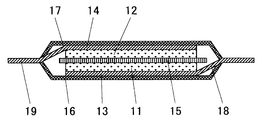
- FIG. 1 shows a cross-sectional view of an example of a lithium ion secondary battery according to this embodiment.
- a lithium ion secondary battery having a positive electrode containing a positive electrode active material, the secondary battery including a single-plate laminate type battery cell.
- the positive electrode includes a positive electrode active material 11 and a positive electrode current collector 13
- the negative electrode includes a negative electrode active material 12 and a negative electrode current collector 14.
- the positive electrode active material 11 and the negative electrode active material 12 face each other with a separator 15 interposed therebetween.
- the positive electrode current collector 13 and the negative electrode current collector 14 are generally made of a metal foil, and the positive electrode active material 11 and the negative electrode active material 12 are applied and solidified on one side of each.
- the ends of the positive electrode current collector 13 and the negative electrode current collector 14 are drawn out of the battery cell as a positive electrode tab 18 and a negative electrode tab 19, respectively, and the battery cell is sealed from above and below by exterior laminates 16 and 17. ing.
- the sealed battery cell is filled with an electrolyte solution.
- an electrolyte solution a non-aqueous organic electrolyte solution in which a lithium salt is dissolved as a supporting salt can be used.
- the lithium ion secondary battery according to the present embodiment is basically not limited in battery shape, and the electrode shape may be a wound type or a laminated type as long as the positive electrode and the negative electrode are opposed to each other with a separator interposed therebetween. It is also possible. Further, the structure of the battery cell can be not only the single plate laminate type but also a coin type, a laminate pack type, a square cell, a cylindrical cell, or the like.
- a lithium ion secondary battery includes a positive electrode including a lithium compound as a positive electrode active material, and a negative electrode including a negative electrode active material capable of occluding and releasing lithium ions. Between the positive electrode and the negative electrode, both In order to prevent electrical connection from occurring, a non-conductive separator and an electrolyte region are provided. Here, both the positive electrode and the negative electrode are held in a state immersed in an electrolyte solution having lithium ion conductivity, and these components are sealed in a container.
- lithium nickel manganese oxide which is a positive electrode active material
- the following raw materials can be used.
- Li raw material Li 2 CO 3 , LiOH, LiNO 3 , Li 2 O, Li 2 SO 4, or the like can be used. Among these, Li 2 CO 3 and LiOH are particularly preferable.
- Ni raw material NiO, Ni (OH) 2 , NiSO 4, Ni (NO 3) 2 and the like can be used.
- Mn raw material examples include various manganese oxides such as electrolytic manganese dioxide (EMD), Mn 2 O 3 , Mn 3 O 4 , and CMD (Chemical Manganese Dioxide), MnCO 3 , MnSO 4 , Mn (CH 3 COO) 2 and the like.
- EMD electrolytic manganese dioxide
- Mn 2 O 3 , Mn 3 O 4 , and CMD Chemical Manganese Dioxide
- MnCO 3 , MnSO 4 , Mn (CH 3 COO) 2 and the like can be used.
- TiO 2 or the like can be used.
- Co raw material CoO, Co 3 O 4 , CoCl 2 , Co (OH) 2 , CoSO 4 , CoCO 3 , Co (NO 3 ) 2 or the like can be used.
- Fe 2 O 3 , Fe 3 O 4 , Fe (OH) 2 , FeOOH, etc. can be used as the Fe raw material.
- Cr raw material Cr (NO 3 ) 3 , Cr 2 O 3 , Cr 2 (CO 3 ) O 3 or the like can be used.
- Al raw material Al (OH) 3 , Al (CH 3 COO) 3 or the like can be used.
- Mg raw material Mg (OH) 2 , Mg (CH 3 COO) 2 or the like can be used.
- B 2 O 3 or the like can be used as the B raw material.
- Si raw material SiO, SiO 2 or the like can be used.
- the obtained mixed powder is fired in air or oxygen at a temperature of 600 ° C. to 950 ° C. to obtain a positive electrode active material.
- the firing temperature is preferably a high temperature for diffusing each element, but if the firing temperature is too high, oxygen deficiency may occur and the battery characteristics may deteriorate. For this reason, the firing temperature is preferably 600 ° C. to 850 ° C.
- baking in an oxygen atmosphere is preferable in order to prevent generation of oxygen deficiency.
- the specific surface area of the positive electrode active material As a method of setting the specific surface area of the positive electrode active material to 0.2 m 2 g ⁇ 1 or more and 1 m 2 g ⁇ 1 or less, it can be adjusted to the above range by adjusting each of the Li amount and the firing temperature. .
- lithium titanium oxide that is a negative electrode active material
- the following raw materials can be used.
- Li raw material Li 2 CO 3 , LiOH, LiNO 3 , Li 2 O, Li 2 SO 4, or the like can be used. Among these, Li 2 CO 3 and LiOH are particularly preferable.
- Ti raw material TiO 2 or the like can be used.
- Ta 2 O 5 or the like can be used as the Ta material
- ZrO 2 or the like can be used as the Zr material
- CrO 2 can be used as the Cr material
- NiO can be used as the Ni material
- VO 2 can be used as the V material.
- the obtained mixed powder is fired in air or oxygen at a temperature of 600 ° C. to 1000 ° C. to obtain a negative electrode active material.
- the firing temperature is preferably a high temperature for diffusing each element, but if the firing temperature is too high, oxygen deficiency may occur and the battery characteristics may deteriorate. Therefore, the firing temperature is preferably 750 ° C to 900 ° C.
- baking in an oxygen atmosphere is preferable in order to prevent generation of oxygen deficiency.
- the specific surface area of the negative electrode active material As a method of setting the specific surface area of the negative electrode active material to 4 m 2 g ⁇ 1 or more and 20 m 2 g ⁇ 1 or less, it can be adjusted to the above range by adjusting each of the Li amount and the firing temperature.
- the produced powdered positive electrode active material and negative electrode active material each have a predetermined crystal structure can be evaluated by powder X-ray diffraction.
- Each powdery lithium compound is set in a powder X-ray diffractometer, and the result obtained by measuring the diffraction angle and intensity of the diffracted light obtained by irradiating characteristic X-rays is obtained as an ICDD Cards (International Center for Diffraction Data).
- the crystal structure is identified by querying Cards: powder X-ray diffraction pattern database card).
- the diffraction patterns of the obtained powdered positive electrode active material and negative electrode active material are Li x (Ni a Mn 2- abM1 b ) O 4 , Li y Ti (5-c). / 3 M2 c O 4 It is possible to identify the crystal structure and the crystallization rate of the compound formed by comparing the diffraction pattern with each crystal structure and measuring the diffraction intensity.
- the obtained positive electrode active material, conductivity imparting agent, binder and solvent are mixed and applied on the surface of the positive electrode current collector to form a film.
- the conductivity-imparting agent include carbon materials such as acetylene black, carbon black, graphite, and fibrous carbon, metal substances such as Al, and conductive oxide powders. These may use only 1 type and may use 2 or more types together.
- the binder in addition to polyvinylidene fluoride (PVDF), fluorine rubber or the like can be used.
- the fluororubber examples include vinylidene fluoride-hexafluoropropylene (VDF-HFP) copolymer, vinylidene fluoride-hexafluoropropylene-tetrafluoroethylene (VDF-HFP-TFE) copolymer, Vinylidene fluoride-pentafluoropropylene (VDF-PFP) copolymer, vinylidene fluoride-pentafluoropropylene-tetrafluoroethylene (VDF-PFP-TFE) copolymer, vinylidene fluoride-perfluoromethyl vinyl ether-tetra Examples thereof include a fluoroethylene (VDF-PFMVE-TFE) copolymer, an ethylene-tetrafluoroethylene copolymer, and a propylene-tetrafluoroethylene copolymer.
- VDF-HFP vinylidene fluoride-hexafluoropropylene
- a fluorine-containing polymer in which hydrogen in the main chain is substituted with an alkyl group can also be used. These may use only 1 type and may use 2 or more types together.
- a metal thin film mainly composed of aluminum, an aluminum alloy, titanium, or the like can be used.
- the preferable addition amount of the conductivity-imparting agent is 0.5 to 30% by mass with respect to the total amount of the positive electrode active material excluding the solvent, the conductivity-imparting agent and the binder.
- a preferable addition amount of the binder is similarly 1 to 10% by mass with respect to the total amount.
- a preferable content ratio of the positive electrode active material is 70% by mass or more and 98.5% by mass or less, and more preferably 85% by mass or more and 97% by mass or less with respect to the total amount.
- the density of the positive electrode active material in the positive electrode active material layer formed by applying the positive electrode active material to the surface of the positive electrode current collector is preferably 1 g / cm 3 or more and 4.5 g / cm 3 or less. More preferably, it is 2 g / cm 3 or more and 4 g / cm 3 or less.
- the density of the positive electrode active material layer exceeds 4.5 g / cm 3 , since there are few voids in the positive electrode active material layer, an electrolyte solution that fills the periphery of the positive electrode of the lithium ion secondary battery becomes a void in the positive electrode. It may be difficult to enter. For this reason, the amount of movement of Li ions is reduced, and the charge / discharge rate characteristics of the battery may be reduced.
- the density of the positive electrode active material layer is less than 1 g / cm 3 , the energy density of the lithium ion secondary battery to be produced is the same as when the content ratio of the positive electrode active material in the positive electrode active material layer is small. May decrease.
- the obtained negative electrode active material, a conductivity imparting agent, a binder, and a solvent are mixed and applied onto the surface of the negative electrode current collector to form a film.
- a conductivity-imparting agent the same conductivity-imparting agent as that used in the production of the positive electrode can be used.
- the binder in addition to polyvinylidene fluoride (PVDF), tetrafluoroethylene, polyvinylidene fluoride, polyethylene, polypropylene, ethylene-propylene diene terpolymer (EPDM), sulfonated EPDM, styrene butadiene rubber (SBR), the fluorine A thermoplastic resin such as rubber or carbomethoxycellulose, a polymer having rubber elasticity, or the like can be used. These may use only 1 type and may use 2 or more types together.
- the negative electrode current collector a metal thin film mainly composed of copper, nickel, or the like can be used.
- the preferable addition amount of the negative electrode active material, the conductivity imparting agent, and the binder is the same as the preferable addition amount of the positive electrode active material, the conductivity imparting agent, and the binder in the positive electrode preparation.
- the density of the negative electrode active material in the negative electrode active material layer formed by applying the negative electrode active material to the surface of the current collector is preferably 2 g / cm 3 or more and 2.5 g / cm 3 or less. The reason why this range is preferable is the same as the density of the positive electrode active material.
- an aprotic organic solvent for the electrolyte solution according to the lithium ion secondary battery in the present embodiment.
- the aprotic organic solvent include ethylene carbonate (EC), propylene carbonate (PC), butylene carbonate (BC), cyclic carbonates such as vinylene carbonate (VC), dimethyl carbonate (DMC), ethyl methyl carbonate (EMC), Linear carbonates such as diethyl carbonate (DEC) and dipropyl carbonate (DPC), aliphatic carboxylic acid esters such as methyl formate, methyl acetate and ethyl propionate, ⁇ -lactones such as ⁇ -butyrolactone, 1, 2 -Chain ethers such as diethoxyethane (DEE) and ethoxymethoxyethane (EME), cyclic ethers such as tetrahydrofuran and 2-methyltetrahydrofuran, dimethyl sulfoxide, 1,3-d
- a polymer or the like added to the aprotic organic solvent to solidify the electrolyte solution into a gel may be used.
- a room temperature molten salt or an ionic liquid represented by a cyclic ammonium cation or the same anion may be used.
- a method in which a cyclic carbonate and a chain carbonate are mixed and used is particularly preferable from the viewpoints of conductivity and stability under a high voltage.
- lithium salt as a supporting salt.
- the lithium salt LiPF 6, LiAsF 6, LiAlCl 4, LiClO 4, LiBF 4, LiSbF 6, LiBOB (Lithium bis (oxalate) borate), LiCF 3 SO 3, LiC 4 F 9 SO 3, LiC (CF 3 SO 2) 3, LiN (CF 3 SO 2) 2, LiN (C 2 F 5 SO 2) 2, LiCH 3 SO 3, LiC 2 H 5 SO 3, LiC 3 H 7 SO 3, lithium lower aliphatic carboxylic acids and Other lithium carboxylates, lithium chloroborane, lithium tetraphenylborate, LiBr, LiI, LiSCN, LiCl, LiF and the like can be mentioned.
- the electrolyte concentration of the dissolved support salt is preferably 0.5 mol / l or more and 1.5 mol / l or less. If the electrolyte concentration of the supporting salt is higher than 1.5 mol / l, the density and viscosity of the electrolyte solution may increase and Li ion migration may be hindered. Conversely, if the electrolyte concentration is lower than 0.5 mol / l, the electrical conductivity of the electrolyte solution may be reduced.
- the separator used in the lithium ion secondary battery of this embodiment is preferably a polymer film such as a propylene film.
- the lithium ion secondary battery according to this embodiment can be manufactured, for example, by the following method.
- a positive electrode active material and a negative electrode active material are respectively formed on the surfaces of the positive electrode current collector and the negative electrode current collector to form a positive electrode and a negative electrode, and a separator is sandwiched between them to form an electrode body.
- an electrolyte solution in a film structure or the like formed by laminating a synthetic resin and a metal foil in dry air or an inert gas atmosphere lithium ions having a single plate laminate type cell A secondary battery can be manufactured.
- the electrode body is further rolled to form a wound body, which is also housed in a battery can in a dry air or inert gas atmosphere, filled with an electrolyte solution, and sealed to form a cylindrical or square cell.
- a lithium ion secondary battery having a shape can be manufactured.
- the potential of the positive electrode of the lithium ion secondary battery produced here is preferably 5.5 V or less with respect to the potential of Li.
- a lithium ion secondary battery has a property that the decomposition of the electrolyte solution proceeds when the positive electrode potential is high, and particularly in order to maintain the reliability of the battery when repeatedly charging and discharging at a high temperature of 60 ° C. or higher. More preferably, the potential of the positive electrode is 5.3 V or less.
- the potential of the negative electrode is preferably 1 V or more with respect to the potential of Li.
- Lithium ion secondary batteries in which the specific surface areas and compositions of the positive electrode active material and the negative electrode active material were changed were produced, and each was used as an example and a comparative example. All of these lithium ion secondary batteries have single-plate laminated cells having the same shape. These lithium ion secondary batteries were held at a high temperature and evaluated for a reduction in discharge capacity. Hereafter, the preparation methods and evaluation methods of the lithium ion secondary battery of an Example and a comparative example are demonstrated.
- Li 2 CO 3 was used as a Li raw material. NiO, MnO 2 , TiO 2 , SiO 2 , CoO, Fe 2 O 3 , Cr 2 O 3 , Al 2 O 3 , MgO, and B 2 O 3 were used as raw materials other than Li.
- the raw materials of Li 2 CO 3 , NiO, MnO 2 , and M1 were weighed so as to have the desired composition ratios, and pulverized and mixed.
- the powder after mixing the raw materials was fired at a temperature range of 750 to 950 ° C. for 9 hours. Then, coarse particles were removed from the mixture through a 30 ⁇ m mesh sieve to obtain a positive electrode active material powder.
- the positive electrode active material had a substantially single-phase spinel structure.
- the specific surface area of the positive electrode active material was measured using a gas adsorption amount measuring device “QS-18” (trade name, manufactured by Quanta Chrome). The method for measuring the specific surface area is the same for the negative electrode active material described later.
- the positive electrode active material powder obtained in the above step and the conductivity-imparting material were dispersed in a solution obtained by dissolving a binder in an organic solvent and kneaded to form a slurry.
- Carbon black which is a carbon material, was used as the conductivity imparting material.
- Polyvinylidene fluoride (PVDF) was used as a binder.
- N-methyl-2-pyrrolidone (NMP) was used as the organic solvent.
- the mass ratio of the positive electrode active material, the conductivity imparting material, and the binder was 90: 6: 4.
- the prepared slurry was applied onto a positive electrode current collector made of an aluminum (Al) foil having a thickness of 20 ⁇ m to form a positive electrode active material layer, thereby obtaining a laminate.
- the initial charge capacity per unit area of the positive electrode to be manufactured (the amount of charge accumulated in the battery when the fully charged non-charged battery is first fully charged) is 2.0 mAh / cm 2.
- the thickness of the positive electrode active material layer to be applied was adjusted.
- the produced laminate was dried and solidified in a vacuum for 12 hours to obtain a positive electrode material.
- This positive electrode material was cut into a square 20 mm long and 20 mm wide. Then, it pressure-molded with the pressure of 3 t / cm ⁇ 2 >, and produced the positive electrode.
- LiOH was used as a Li raw material.
- raw materials other than Li TiO 2 , Ta 2 O 5 , ZrO 2 , CrO 2 , NiO, and VO 2 were used.
- the raw materials of LiOH, TiO 2 and M2 were weighed so as to have the desired composition ratios, and pulverized and mixed.
- the powder after mixing the raw materials was fired at a temperature range of 700 to 1000 ° C. for 12 hours. Then, coarse particles were removed from the mixture through a 2 ⁇ m mesh sieve to obtain a powder of a negative electrode active material.
- the same powder X-ray diffraction as described above was confirmed to have a substantially single-phase spinel structure.
- the negative electrode active material powder obtained in the above step and the conductivity-imparting material were dispersed in a solution obtained by dissolving a binder in an organic solvent and kneaded to form a slurry.
- Carbon black which is a carbon material, was used as the conductivity imparting material.
- Polyvinylidene fluoride (PVDF) was used as a binder.
- NMP N-methyl-2-pyrrolidone
- the prepared slurry was applied on a negative electrode current collector made of a copper (Cu) foil having a thickness of 10 ⁇ m to form a negative electrode active material layer, thereby obtaining a laminate.
- the thickness of the negative electrode active material layer to be applied was adjusted so that the initial charge capacity per unit area of the negative electrode to be manufactured was 2.6 mAh / cm 2 .
- the produced laminate was dried and solidified in a vacuum for 12 hours to obtain a negative electrode material.
- This negative electrode material was cut into a square of 22 mm length and 22 mm width. Then, it pressure-molded with the pressure of 1 t / cm ⁇ 2 >, and produced the negative electrode.
- the positive electrode and the negative electrode produced by the above method were arranged so that the active material layers of the positive electrode and the negative electrode face each other, and were placed in a battery cell as a laminate cell with a separator interposed therebetween.
- a polypropylene film as an insulator was used as the separator, and the shape of the separator was larger than that of either the positive electrode or the negative electrode. For this reason, the positive electrode and the negative electrode are insulated from each other by the separator.
- an Al tab which is a lead leading out of the battery, is joined to the end of the positive electrode current collector, and a nickel (Ni) tab of the lead lead is similarly joined to the end of the negative electrode current collector.
- lithium ion secondary battery having a single-plate laminate type battery cell was assembled.
- 10 lithium ion secondary batteries each having a positive electrode active material having the same composition were produced by a series of these assembly steps.
- the following evaluation was implemented with respect to the lithium ion secondary battery produced by the said process.
- the prepared lithium ion secondary battery was charged by a constant current and constant voltage method with an upper limit voltage of 3.4 V and a current value of 1.6 mA, and was fully charged (initial charge).
- the discharge was performed at a constant current with the lower limit voltage being 1.5 V (initial discharge).
- the discharge capacity at this time (the amount of charge taken out from the battery by the initial discharge) is defined as the initial discharge capacity.
- the battery was charged again under the same charging conditions as the initial charge to obtain a fully charged state, and the battery was kept at 60 ° C. and stored for 90 days.
- the upper limit voltage is set to 3.4 V and the current density is 50 times that of the initial charge.
- a rapid charge for 15 minutes was performed by a constant current constant voltage method at a current value of 80 mA.
- discharging was performed again at a constant current of 1.6 mA to a lower limit voltage of 1.5 V, and the discharge capacity at that time was measured. This is defined as the discharge capacity after holding.
- the ratio of the discharge capacity value after holding to the initial discharge capacity in each battery is measured and the specific surface area and composition of the positive electrode active material and the negative electrode active material are changed, how the ratio value of the discharge capacity changes Each was evaluated.
- the initial charge capacity of each battery is set to a constant value of 2.0 mAh / cm 2 , and the size of the positive electrode that captures and releases Li ions is the same for each battery. It is 20 mm long and 20 mm wide. Therefore, the initial charge capacity of each battery is the same at 8 mAh. Therefore, if each battery is charged at a constant current of 8 mA, it can be almost fully charged in one hour.
- charging at a constant current of 8 mA is referred to as 1C.
- the upper limit voltage is set at the time of charging, the actual charging of each battery is constant current constant voltage charging that shifts to constant voltage charging when the charging voltage reaches the upper limit voltage.
- charging is initially performed at a constant current of 80 mA, and when the upper limit voltage is reached, the charging is switched to constant voltage charging.
- the fast charge for 15 minutes at the current value of 80 mA after the discharge after storage at 60 ° C. for 90 days in the evaluation of the lithium ion secondary battery is this constant current / constant voltage charge at 10 C15.
- a lithium ion secondary battery in which the specific surface area and composition of the positive electrode active material and the negative electrode active material were changed under the above production conditions was produced as Examples and Comparative Examples.
- the ratio (hereinafter, capacity retention rate) was evaluated.
- the evaluation results are shown in Tables 1 to 7, respectively.
- the composition of each lithium compound in the positive electrode active material constituting each lithium ion secondary battery, the capacity retention rate value (unit%) in each composition, and the determination (A and B) are shown. Show.
- the lithium ion secondary battery evaluated for every composition is 10 pieces each, and the value of the capacity maintenance rate in the battery of each composition is an average value of the measured value in these 10 batteries.
- the evaluation method of the capacity maintenance rate before and after holding at high temperature in this example is equivalent to JIS C8711 for the evaluation standard for determining the case where it is 50% or more, but it depends on the severity of the actual test contents. , Substantially exceeding the standards of JIS C8711.
- the reason why the battery evaluation method in this example was made to be a stricter standard compared with the general method defined in the Japanese Industrial Standard is that lithium ions mounted on portable electronic devices in recent years. This is because the secondary battery demands a product that satisfies a stricter level than ever before in terms of maintaining the charging capacity during long-term use.
- a lithium ion secondary battery that satisfies the evaluation criteria employed in this example has more excellent characteristics with respect to capacity retention during long-term storage.
- the configuration of the positive electrode active material and the negative electrode active material is specifically specified, and thereby excellent characteristics are obtained.
- Example 1 The positive electrode active material and the negative electrode active material composing the lithium ion secondary battery were fixed, and batteries were prepared by changing the specific surface area of each lithium compound. Examples 1 to 11 and Comparative Examples 1 to 7 were respectively used. It was. Table 1 shows the evaluation results of the capacity retention rates.
- the compositions of the positive electrode active material and the negative electrode active material are LiNi 0.5 Mn 1.5 O 4 and Li 4/3 Ti 5/3 O 4 , respectively.
- a predetermined specific surface area was obtained by appropriately adjusting the firing temperature during the production of the positive electrode active material and the negative electrode active material.
- the conditions for the capacity retention rate to be 50% or more are that the specific surface area of the positive electrode active material is 0.2 m 2 g ⁇ 1 or more, 1 m 2 g ⁇ 1 or less, the negative electrode In this case, the specific surface area of the active material satisfies the range of 4 m 2 g ⁇ 1 or more and 20 m 2 g ⁇ 1 or less.
- Example 12 to 15 Comparative Examples 8 to 11
- the composition of the negative electrode active material was Li 4/3 Ti 5/3 O 4 and the specific surface area was 5 m 2 g ⁇ 1 .
- Batteries in which the specific surface area of the positive electrode active material was fixed to 0.5 m 2 g ⁇ 1 and only the amount of Ni in the positive electrode active material was changed were prepared, and were designated as Examples 12 to 15 and Comparative Examples 8 to 11, respectively.
- Table 2 shows the evaluation results of the capacity retention rates.
- Table 6 shows Example 6 described above.
- Example 16 to 27, Comparative Examples 12 to 15 The composition of the negative electrode active material was Li 4/3 Ti 5/3 O 4 and the specific surface area was 10 m 2 g ⁇ 1 . Batteries were prepared by fixing the specific surface area of the positive electrode active material to 0.5 m 2 g ⁇ 1 and changing only the amount of M1 of the positive electrode active material, and were designated as Examples 16 to 27 and Comparative Examples 12 to 15, respectively. Table 3 shows the evaluation results of the capacity retention rates. For comparison, Table 9 shows Example 9 described above.
- Example 28 to 32 Comparative Example 16
- the composition of the negative electrode active material was Li 4/3 Ti 5/3 O 4 and the specific surface area was 20 m 2 g ⁇ 1 .
- Batteries in which the specific surface area of the positive electrode active material was fixed at 0.5 m 2 g ⁇ 1 , the amount of M1 was fixed at 0.1, and only M1 was changed were produced, which were designated as Examples 28 to 32 and Comparative Example 16, respectively.
- Table 4 shows the evaluation results of the capacity retention rates.
- Example 33 to 40 The composition of the negative electrode active material was Li 4/3 Ti 5/3 O 4 and the specific surface area was 20 m 2 g ⁇ 1 .
- Examples 33 to 40 were produced by preparing batteries in which the specific surface area of the positive electrode active material was fixed at 0.5 m 2 g ⁇ 1 , M1 was 2 or more, and the compositions were changed. Table 5 shows the evaluation results of the capacity retention rates.
- Example 41 to 45 Comparative Examples 17 and 18
- the composition of the positive electrode active material was LiNi 0.45 Li 0.05 Mn 1.4 Ti 0.1 O 4 and the specific surface area was 0.5 m 2 g ⁇ 1 .
- Batteries were prepared by fixing the specific surface area of the negative electrode active material to 20 m 2 g ⁇ 1 and changing only c in the formula (II), which was the amount of M2 and M2 of the negative electrode active material. Examples 17 and 18 were designated. Table 6 shows the evaluation results of the capacity retention rates.
- Example 46 to 48 Comparative Example 19
- the composition of the positive electrode active material was LiNi 0.4 Li 0.05 Al 0.05 Mn 1.4 Si 0.1 O 4 and the specific surface area was 0.5 m 2 g ⁇ 1 .
- Batteries were prepared by fixing the specific surface area of the negative electrode active material to 20 m 2 g ⁇ 1 and changing only c in the formula (II), which was the amount of M2 and M2 of the negative electrode active material.
- Example 19 was adopted. Table 7 shows the evaluation results of the capacity retention rates.
- the lithium ion secondary battery according to the present embodiment can maintain sufficient rapid charging characteristics even after long-term use by the user. Therefore, according to the present embodiment, it is possible to provide a lithium ion secondary battery having high reliability that is actually used by a user. That is, according to this embodiment, it was found that a lithium ion secondary battery capable of rapid charging can be provided.
Landscapes
- Chemical & Material Sciences (AREA)
- Chemical Kinetics & Catalysis (AREA)
- Electrochemistry (AREA)
- General Chemical & Material Sciences (AREA)
- Inorganic Chemistry (AREA)
- Engineering & Computer Science (AREA)
- Materials Engineering (AREA)
- Manufacturing & Machinery (AREA)
- Battery Electrode And Active Subsutance (AREA)
- Secondary Cells (AREA)
Abstract
L'invention concerne une batterie secondaire au lithium-ion à faible perte de capacité de batterie en mode charge rapide, et à haute densité d'énergie. Plus précisément, l'invention concerne une batterie secondaire au lithium-ion dans laquelle une électrode positive contient un oxyde de lithium-nickel-manganèse représenté par la formule (I) LixNiaM1bMn2-a-bO4 (Dans la formule (I), M1 représente au moins un élément choisi dans un groupe constitué de Ti, Si, Co, Fe, Cr, Al, Mg, B, et Li. 0<x≦1, 0,4≦a≦0,6 et 0≦b≦0,4), et dont la surface spécifique est de 0,2 à 1m2g-1; et une électrode négative contient un oxyde de lithium-titane représenté par la formule (II) LiyTi5/3-cM2cO4 (Dans la formule (II), M2 représente au moins un élément choisi dans un groupe constitué de Ta, Zr, Cr, Ni, et V. 4/3≦y≦7/3 et 0≦c<0,1), et dont la surface spécifique est de 4 à 20 m2g-1.
Priority Applications (3)
| Application Number | Priority Date | Filing Date | Title |
|---|---|---|---|
| CN201180036920.3A CN103004005B (zh) | 2010-07-28 | 2011-07-22 | 锂离子二次电池 |
| EP11812383.5A EP2600458B1 (fr) | 2010-07-28 | 2011-07-22 | Batterie secondaire au lithium-ion |
| US13/811,030 US20130122373A1 (en) | 2010-07-28 | 2011-07-22 | Lithium ion secondary battery |
Applications Claiming Priority (2)
| Application Number | Priority Date | Filing Date | Title |
|---|---|---|---|
| JP2010169248A JP2012033279A (ja) | 2010-07-28 | 2010-07-28 | リチウムイオン二次電池 |
| JP2010-169248 | 2010-07-28 |
Publications (1)
| Publication Number | Publication Date |
|---|---|
| WO2012014793A1 true WO2012014793A1 (fr) | 2012-02-02 |
Family
ID=45530001
Family Applications (1)
| Application Number | Title | Priority Date | Filing Date |
|---|---|---|---|
| PCT/JP2011/066657 WO2012014793A1 (fr) | 2010-07-28 | 2011-07-22 | Batterie secondaire au lithium-ion |
Country Status (5)
| Country | Link |
|---|---|
| US (1) | US20130122373A1 (fr) |
| EP (1) | EP2600458B1 (fr) |
| JP (1) | JP2012033279A (fr) |
| CN (1) | CN103004005B (fr) |
| WO (1) | WO2012014793A1 (fr) |
Cited By (8)
| Publication number | Priority date | Publication date | Assignee | Title |
|---|---|---|---|---|
| WO2013153690A1 (fr) * | 2012-04-13 | 2013-10-17 | 日本電気株式会社 | Matériau actif d'électrode positive pour pile rechargeable, et pile rechargeable mettant en œuvre ledit matériau |
| WO2013161949A1 (fr) * | 2012-04-27 | 2013-10-31 | 三井金属鉱業株式会社 | Oxyde de métal de transition lithié de type spinelle de manganèse |
| US20140349171A1 (en) * | 2012-04-16 | 2014-11-27 | Lg Chem, Ltd. | Method of manufacturing electrode for lithium secondary battery and electrode manufactured using the same |
| JP2015513182A (ja) * | 2012-04-16 | 2015-04-30 | エルジー・ケム・リミテッド | リチウム二次電池用電極の製造方法及びそれを用いて製造される電極 |
| EP2806491A4 (fr) * | 2012-04-17 | 2015-06-17 | Lg Chemical Ltd | Batterie rechargeable au lithium présentant une excellente performance |
| EP2811569A4 (fr) * | 2012-04-17 | 2015-06-24 | Lg Chemical Ltd | Batterie rechargeable au lithium présentant une excellente performance |
| EP2811570A4 (fr) * | 2012-04-17 | 2015-06-24 | Lg Chemical Ltd | Batterie rechargeable au lithium présentant une excellente performance |
| CN104956537A (zh) * | 2013-04-11 | 2015-09-30 | 株式会社Lg化学 | 包含具有不同表面积的电极的电极层压物和使用所述电极层压物的二次电池 |
Families Citing this family (37)
| Publication number | Priority date | Publication date | Assignee | Title |
|---|---|---|---|---|
| WO2012147864A1 (fr) * | 2011-04-28 | 2012-11-01 | 石原産業株式会社 | Procédé de fabrication de précurseur de titanate de lithium, procédé de fabrication de titanate de lithium, titanate de lithium, substance active d'électrode et dispositif de stockage |
| JP2013178916A (ja) * | 2012-02-28 | 2013-09-09 | Murata Mfg Co Ltd | 非水電解質二次電池 |
| CN104321915A (zh) * | 2012-04-17 | 2015-01-28 | 株式会社Lg化学 | 制造锂二次电池用电极的方法和使用其制造的电极 |
| KR101497351B1 (ko) * | 2012-04-17 | 2015-03-03 | 주식회사 엘지화학 | 과량의 전해액을 포함하는 리튬 이차전지 |
| KR101497348B1 (ko) * | 2012-04-18 | 2015-03-05 | 주식회사 엘지화학 | 리튬 이차전지용 일체형 전극조립체의 제조방법 및 이를 사용하여 제조되는 일체형 전극조립체 |
| WO2013157873A1 (fr) | 2012-04-18 | 2013-10-24 | 주식회사 엘지화학 | Électrode pour batterie rechargeable et batterie rechargeable la comprenant |
| KR101483205B1 (ko) * | 2012-04-18 | 2015-01-16 | 주식회사 엘지화학 | 전해액 함침성 및 안전성이 향상된 전극조립체 및 이를 포함하는 리튬 이차전지 |
| KR101493255B1 (ko) | 2012-04-19 | 2015-02-16 | 주식회사 엘지화학 | 전극의 제조방법 및 이를 사용하여 제조되는 전극 |
| CN104704657A (zh) | 2012-06-01 | 2015-06-10 | 纳幕尔杜邦公司 | 锂离子电池 |
| KR101555833B1 (ko) | 2012-06-29 | 2015-09-30 | 주식회사 엘지화학 | 전극조립체 및 이를 포함하는 리튬 이차전지 |
| JP6386840B2 (ja) * | 2013-09-13 | 2018-09-05 | 株式会社東芝 | 非水電解質二次電池および電池パック |
| CN103700840A (zh) * | 2014-01-08 | 2014-04-02 | 山东精工电子科技有限公司 | 一种高电压锂电池正极材料及其制备方法 |
| CN103872313B (zh) * | 2014-03-10 | 2017-04-05 | 电子科技大学 | 锂离子电池正极材料LiMn2‑2xM(II)xSixO4及其制备方法 |
| CN103872312B (zh) * | 2014-03-10 | 2017-02-01 | 电子科技大学 | 锂离子电池正极材料LiMn2‑2xM(II)xTixO4及其制备方法 |
| JP6350321B2 (ja) * | 2014-03-24 | 2018-07-04 | 日亜化学工業株式会社 | 非水電解液二次電池用正極活物質 |
| WO2015151376A1 (fr) * | 2014-04-03 | 2015-10-08 | ソニー株式会社 | Batterie rechargeable, bloc de batteries, dispositif électronique, véhicule électrique, dispositif de stockage d'électricité et système électrique |
| EP3128594B1 (fr) * | 2014-04-03 | 2019-07-31 | Murata Manufacturing Co., Ltd. | Batterie rechargeable, bloc-batterie, dispositif électronique, véhicule électrique, dispositif de stockage d'électricité, et système d'alimentation électrique |
| JP2015201335A (ja) * | 2014-04-08 | 2015-11-12 | 日立化成株式会社 | リチウムイオン電池 |
| CA2956380A1 (fr) * | 2014-07-25 | 2016-01-28 | Advanced Lithium Electrochemistry Co., Ltd. | Procede de preparation de materiau d'anode d'oxyde de lithium-nickel-manganese |
| DE112016001116T5 (de) * | 2015-03-10 | 2017-11-30 | The University Of Tokyo | Elektrolytlösung |
| JP6128196B2 (ja) * | 2015-03-24 | 2017-05-17 | 日亜化学工業株式会社 | 非水電解液二次電池用正極活物質 |
| US9966601B2 (en) | 2015-03-24 | 2018-05-08 | Nichia Corporation | Positive electrode active material for nonaqueous electrolyte secondary battery |
| JP6308396B2 (ja) * | 2015-04-10 | 2018-04-11 | トヨタ自動車株式会社 | 非水電解液二次電池 |
| US10957936B2 (en) | 2015-11-06 | 2021-03-23 | Showa Denko Materials Co., Ltd. | Lithium ion secondary battery |
| FR3045211B1 (fr) * | 2015-12-09 | 2020-06-05 | Commissariat A L'energie Atomique Et Aux Energies Alternatives | Materiau de cathode pour batteries li-ion |
| KR102272269B1 (ko) * | 2016-10-10 | 2021-07-02 | 삼성에스디아이 주식회사 | 리튬 이차 전지용 양극 및 이를 포함하는 리튬 이차 전지 |
| TWI645607B (zh) * | 2016-12-30 | 2018-12-21 | 財團法人工業技術研究院 | 鋰電池高電壓正極材料及其製備方法 |
| US11978904B2 (en) | 2017-02-24 | 2024-05-07 | Honeycomb Battery Company | Polymer binder for lithium battery and method of manufacturing |
| US10840502B2 (en) | 2017-02-24 | 2020-11-17 | Global Graphene Group, Inc. | Polymer binder for lithium battery and method of manufacturing |
| US11742475B2 (en) | 2017-04-03 | 2023-08-29 | Global Graphene Group, Inc. | Encapsulated anode active material particles, lithium secondary batteries containing same, and method of manufacturing |
| EP3637541B1 (fr) * | 2017-06-08 | 2022-01-26 | National Institute for Materials Science | Batterie lithium-air utilisant un électrolyte non-aqueux |
| KR102308723B1 (ko) * | 2017-10-19 | 2021-10-05 | 주식회사 엘지에너지솔루션 | 음극 활물질, 상기 음극 활물질을 포함하는 음극, 및 상기 음극을 포함하는 이차 전지 |
| CN108448109B (zh) * | 2018-03-23 | 2021-07-02 | 中南大学 | 一种层状富锂锰基正极材料及其制备方法 |
| US11223049B2 (en) | 2018-08-24 | 2022-01-11 | Global Graphene Group, Inc. | Method of producing protected particles of cathode active materials for lithium batteries |
| US11637291B2 (en) | 2020-11-04 | 2023-04-25 | Global Graphene Group, Inc. | Lithium-protecting polymer layer for an anode-less lithium metal secondary battery and manufacturing method |
| JP7325469B2 (ja) * | 2021-03-30 | 2023-08-14 | プライムプラネットエナジー&ソリューションズ株式会社 | 非水電解液二次電池の製造方法 |
| WO2023162669A1 (fr) * | 2022-02-28 | 2023-08-31 | 株式会社レゾナック | Électrolyte solide conducteur d'ions lithium |
Citations (7)
| Publication number | Priority date | Publication date | Assignee | Title |
|---|---|---|---|---|
| JP2000156229A (ja) | 1998-11-20 | 2000-06-06 | Yuasa Corp | 非水電解質リチウム二次電池 |
| JP2000235857A (ja) | 1998-12-18 | 2000-08-29 | Sanyo Electric Co Ltd | リチウム二次電池 |
| JP2001176557A (ja) | 1999-12-20 | 2001-06-29 | Toyota Central Res & Dev Lab Inc | 非水電解液二次電池 |
| JP2005317512A (ja) * | 2004-03-31 | 2005-11-10 | Toshiba Corp | 非水電解質電池 |
| JP2006066341A (ja) | 2004-08-30 | 2006-03-09 | Toshiba Corp | 非水電解質二次電池 |
| JP2007087875A (ja) * | 2005-09-26 | 2007-04-05 | Toshiba Corp | 非水電解質電池および電池パック |
| JP2010169248A (ja) | 2008-12-26 | 2010-08-05 | Hitachi Automotive Systems Ltd | ディスクブレーキ |
Family Cites Families (21)
| Publication number | Priority date | Publication date | Assignee | Title |
|---|---|---|---|---|
| JPH1027609A (ja) * | 1996-07-09 | 1998-01-27 | Matsushita Electric Ind Co Ltd | 非水電解液二次電池 |
| JPH10172571A (ja) * | 1996-12-16 | 1998-06-26 | Aichi Steel Works Ltd | リチウム二次電池及びその正極活物質の製造方法 |
| JP2000058058A (ja) * | 1998-08-03 | 2000-02-25 | Masayuki Yoshio | リチウム二次電池用スピネル系マンガン酸化物 |
| JP3595734B2 (ja) * | 1999-02-15 | 2004-12-02 | 株式会社デンソー | 非水電解液二次電池用正極活物質、その正極活物質の製法、及びその正極活物質を用いた二次電池 |
| JP2002042814A (ja) * | 2000-07-28 | 2002-02-08 | Hitachi Maxell Ltd | 非水二次電池用正極活物質およびそれを用いた非水二次電池 |
| JP2002145617A (ja) * | 2000-11-09 | 2002-05-22 | Nippon Chem Ind Co Ltd | リチウムマンガン複合酸化物およびその製造方法 |
| JP5013386B2 (ja) * | 2000-11-17 | 2012-08-29 | 日立マクセルエナジー株式会社 | 非水二次電池用正極活物質およびそれを用いた非水二次電池 |
| JP2003115324A (ja) * | 2001-10-04 | 2003-04-18 | Japan Storage Battery Co Ltd | 非水電解質電池。 |
| JP4325167B2 (ja) * | 2001-10-18 | 2009-09-02 | 日本電気株式会社 | 非水電解液二次電池用電極材料 |
| JP4192477B2 (ja) * | 2002-03-08 | 2008-12-10 | 日本電気株式会社 | 二次電池用正極活物質およびそれを用いた二次電池用正極および二次電池 |
| JP4541709B2 (ja) * | 2002-03-27 | 2010-09-08 | 株式会社Gsユアサ | 正極活物質およびそれを用いた非水電解質電池 |
| JP2006219323A (ja) * | 2005-02-09 | 2006-08-24 | Sumitomo Metal Mining Co Ltd | リチウムマンガンニッケルアルミニウム複合酸化物およびその製造方法 |
| JP4213687B2 (ja) * | 2005-07-07 | 2009-01-21 | 株式会社東芝 | 非水電解質電池及び電池パック |
| JP4213688B2 (ja) * | 2005-07-07 | 2009-01-21 | 株式会社東芝 | 非水電解質電池及び電池パック |
| JP5068459B2 (ja) * | 2006-01-25 | 2012-11-07 | Necエナジーデバイス株式会社 | リチウム二次電池 |
| JP4334579B2 (ja) * | 2007-03-28 | 2009-09-30 | 株式会社東芝 | 非水電解質電池用負極活物質、非水電解質電池、電池パック及び自動車 |
| JP5115697B2 (ja) * | 2007-05-22 | 2013-01-09 | Necエナジーデバイス株式会社 | リチウム二次電池用正極及びそれを用いたリチウム二次電池 |
| JP5300502B2 (ja) * | 2008-03-13 | 2013-09-25 | 株式会社東芝 | 電池用活物質、非水電解質電池および電池パック |
| CN101567442A (zh) * | 2008-07-28 | 2009-10-28 | 新乡市中科科技有限公司 | 一种尖晶石复合钛酸锂的制备方法 |
| JP5258499B2 (ja) * | 2008-10-15 | 2013-08-07 | 日立マクセル株式会社 | 非水二次電池 |
| CN101764207B (zh) * | 2009-09-25 | 2012-01-18 | 合肥工业大学 | 一种锂离子电池负极材料钛酸锂及其制备方法 |
-
2010
- 2010-07-28 JP JP2010169248A patent/JP2012033279A/ja active Pending
-
2011
- 2011-07-22 WO PCT/JP2011/066657 patent/WO2012014793A1/fr active Application Filing
- 2011-07-22 US US13/811,030 patent/US20130122373A1/en not_active Abandoned
- 2011-07-22 CN CN201180036920.3A patent/CN103004005B/zh active Active
- 2011-07-22 EP EP11812383.5A patent/EP2600458B1/fr active Active
Patent Citations (7)
| Publication number | Priority date | Publication date | Assignee | Title |
|---|---|---|---|---|
| JP2000156229A (ja) | 1998-11-20 | 2000-06-06 | Yuasa Corp | 非水電解質リチウム二次電池 |
| JP2000235857A (ja) | 1998-12-18 | 2000-08-29 | Sanyo Electric Co Ltd | リチウム二次電池 |
| JP2001176557A (ja) | 1999-12-20 | 2001-06-29 | Toyota Central Res & Dev Lab Inc | 非水電解液二次電池 |
| JP2005317512A (ja) * | 2004-03-31 | 2005-11-10 | Toshiba Corp | 非水電解質電池 |
| JP2006066341A (ja) | 2004-08-30 | 2006-03-09 | Toshiba Corp | 非水電解質二次電池 |
| JP2007087875A (ja) * | 2005-09-26 | 2007-04-05 | Toshiba Corp | 非水電解質電池および電池パック |
| JP2010169248A (ja) | 2008-12-26 | 2010-08-05 | Hitachi Automotive Systems Ltd | ディスクブレーキ |
Cited By (20)
| Publication number | Priority date | Publication date | Assignee | Title |
|---|---|---|---|---|
| WO2013153690A1 (fr) * | 2012-04-13 | 2013-10-17 | 日本電気株式会社 | Matériau actif d'électrode positive pour pile rechargeable, et pile rechargeable mettant en œuvre ledit matériau |
| US9236602B2 (en) | 2012-04-13 | 2016-01-12 | Nec Corporation | Positive electrode active material for secondary battery and secondary battery using the same |
| JPWO2013153690A1 (ja) * | 2012-04-13 | 2015-12-17 | 日本電気株式会社 | 二次電池用正極活物質及びそれを使用した二次電池 |
| JP2015513182A (ja) * | 2012-04-16 | 2015-04-30 | エルジー・ケム・リミテッド | リチウム二次電池用電極の製造方法及びそれを用いて製造される電極 |
| US9780359B2 (en) | 2012-04-16 | 2017-10-03 | Lg Chem, Ltd. | Method of manufacturing electrode for lithium secondary battery and electrode manufactured using the same |
| US20140349171A1 (en) * | 2012-04-16 | 2014-11-27 | Lg Chem, Ltd. | Method of manufacturing electrode for lithium secondary battery and electrode manufactured using the same |
| US10026952B2 (en) * | 2012-04-16 | 2018-07-17 | Lg Chem, Ltd. | Method of manufacturing electrode for lithium secondary battery and electrode manufactured using the same |
| EP2811570A4 (fr) * | 2012-04-17 | 2015-06-24 | Lg Chemical Ltd | Batterie rechargeable au lithium présentant une excellente performance |
| US9564635B2 (en) | 2012-04-17 | 2017-02-07 | Lg Chem, Ltd. | Lithium secondary battery with excellent performance |
| EP2811569A4 (fr) * | 2012-04-17 | 2015-06-24 | Lg Chemical Ltd | Batterie rechargeable au lithium présentant une excellente performance |
| US9825293B2 (en) | 2012-04-17 | 2017-11-21 | Lg Chem, Ltd. | Lithium battery having higher performance |
| US9899663B2 (en) | 2012-04-17 | 2018-02-20 | Lg Chem, Ltd. | Lithium secondary battery with excellent performance |
| EP2806491A4 (fr) * | 2012-04-17 | 2015-06-17 | Lg Chemical Ltd | Batterie rechargeable au lithium présentant une excellente performance |
| GB2516185A (en) * | 2012-04-27 | 2015-01-14 | Mitsui Mining & Smelting Co | Manganese spinel-type lithium transition metal oxide |
| JP5523637B2 (ja) * | 2012-04-27 | 2014-06-18 | 三井金属鉱業株式会社 | マンガン系スピネル型リチウム遷移金属酸化物 |
| WO2013161949A1 (fr) * | 2012-04-27 | 2013-10-31 | 三井金属鉱業株式会社 | Oxyde de métal de transition lithié de type spinelle de manganèse |
| US9537140B2 (en) | 2012-04-27 | 2017-01-03 | Mitsui Mining & Smelting Co., Ltd. | Manganese spinel-type lithium transition metal oxide |
| CN104956537A (zh) * | 2013-04-11 | 2015-09-30 | 株式会社Lg化学 | 包含具有不同表面积的电极的电极层压物和使用所述电极层压物的二次电池 |
| EP2919314A4 (fr) * | 2013-04-11 | 2016-05-25 | Lg Chemical Ltd | Stratifié d'électrodes comprenant des électrodes ayant différentes aires et batterie secondaire comprenant celui-ci |
| US9666909B2 (en) | 2013-04-11 | 2017-05-30 | Lg Chem, Ltd. | Electrode laminate comprising electrodes with different surface areas and secondary battery employed with the same |
Also Published As
| Publication number | Publication date |
|---|---|
| US20130122373A1 (en) | 2013-05-16 |
| JP2012033279A (ja) | 2012-02-16 |
| EP2600458B1 (fr) | 2018-03-14 |
| EP2600458A1 (fr) | 2013-06-05 |
| EP2600458A4 (fr) | 2016-08-24 |
| CN103004005A (zh) | 2013-03-27 |
| CN103004005B (zh) | 2016-05-25 |
Similar Documents
| Publication | Publication Date | Title |
|---|---|---|
| WO2012014793A1 (fr) | Batterie secondaire au lithium-ion | |
| JP5495300B2 (ja) | リチウムイオン二次電池 | |
| JP5641560B2 (ja) | 二次電池用正極活物質及びそれを使用した二次電池 | |
| JP4853608B2 (ja) | リチウム二次電池 | |
| JP5278994B2 (ja) | リチウム二次電池 | |
| US9356284B2 (en) | Active material for secondary battery | |
| JP6607188B2 (ja) | 正極及びそれを用いた二次電池 | |
| JP6007904B2 (ja) | 二次電池用活物質およびそれを使用した二次電池 | |
| JP6762377B2 (ja) | リチウムイオン二次電池 | |
| JP5046602B2 (ja) | 二次電池用正極、およびそれを用いた二次電池 | |
| JP5322259B2 (ja) | 二次電池用正極およびこれを使用したリチウム二次電池 | |
| JP2010097845A (ja) | 二次電池用正極活物質およびそれを使用した二次電池 | |
| CN110073534B (zh) | 非水电解质二次电池 | |
| JP5483413B2 (ja) | リチウムイオン二次電池 | |
| WO2014171518A2 (fr) | Batterie secondaire lithium-ion | |
| JP5942852B2 (ja) | 二次電池用正極活物質及びそれを使用した二次電池 | |
| JP5360870B2 (ja) | リチウムイオン二次電池用正極、およびそれを用いたリチウムイオン二次電池 | |
| JP5376640B2 (ja) | リチウムイオン二次電池 | |
| JP4867153B2 (ja) | 非水電解液二次電池用の正極活物質、二次電池用正極および非水電解液二次電池 | |
| JP5605867B2 (ja) | 二次電池用正極およびこれを使用したリチウム二次電池 | |
| JP4991225B2 (ja) | 二次電池用正極活物質、それを用いた二次電池用正極および二次電池 |
Legal Events
| Date | Code | Title | Description |
|---|---|---|---|
| 121 | Ep: the epo has been informed by wipo that ep was designated in this application |
Ref document number: 11812383 Country of ref document: EP Kind code of ref document: A1 |
|
| WWE | Wipo information: entry into national phase |
Ref document number: 2011812383 Country of ref document: EP |
|
| WWE | Wipo information: entry into national phase |
Ref document number: 13811030 Country of ref document: US |
|
| NENP | Non-entry into the national phase |
Ref country code: DE |