WO2011101988A1 - 危険度算出装置 - Google Patents
危険度算出装置 Download PDFInfo
- Publication number
- WO2011101988A1 WO2011101988A1 PCT/JP2010/052634 JP2010052634W WO2011101988A1 WO 2011101988 A1 WO2011101988 A1 WO 2011101988A1 JP 2010052634 W JP2010052634 W JP 2010052634W WO 2011101988 A1 WO2011101988 A1 WO 2011101988A1
- Authority
- WO
- WIPO (PCT)
- Prior art keywords
- risk level
- risk
- information
- amount
- host vehicle
- Prior art date
Links
Images


Classifications
-
- G—PHYSICS
- G08—SIGNALLING
- G08G—TRAFFIC CONTROL SYSTEMS
- G08G1/00—Traffic control systems for road vehicles
- G08G1/16—Anti-collision systems
- G08G1/167—Driving aids for lane monitoring, lane changing, e.g. blind spot detection
-
- B—PERFORMING OPERATIONS; TRANSPORTING
- B60—VEHICLES IN GENERAL
- B60Q—ARRANGEMENT OF SIGNALLING OR LIGHTING DEVICES, THE MOUNTING OR SUPPORTING THEREOF OR CIRCUITS THEREFOR, FOR VEHICLES IN GENERAL
- B60Q9/00—Arrangement or adaptation of signal devices not provided for in one of main groups B60Q1/00 - B60Q7/00, e.g. haptic signalling
- B60Q9/008—Arrangement or adaptation of signal devices not provided for in one of main groups B60Q1/00 - B60Q7/00, e.g. haptic signalling for anti-collision purposes
-
- G—PHYSICS
- G08—SIGNALLING
- G08G—TRAFFIC CONTROL SYSTEMS
- G08G1/00—Traffic control systems for road vehicles
- G08G1/16—Anti-collision systems
- G08G1/166—Anti-collision systems for active traffic, e.g. moving vehicles, pedestrians, bikes
-
- B—PERFORMING OPERATIONS; TRANSPORTING
- B60—VEHICLES IN GENERAL
- B60W—CONJOINT CONTROL OF VEHICLE SUB-UNITS OF DIFFERENT TYPE OR DIFFERENT FUNCTION; CONTROL SYSTEMS SPECIALLY ADAPTED FOR HYBRID VEHICLES; ROAD VEHICLE DRIVE CONTROL SYSTEMS FOR PURPOSES NOT RELATED TO THE CONTROL OF A PARTICULAR SUB-UNIT
- B60W50/00—Details of control systems for road vehicle drive control not related to the control of a particular sub-unit, e.g. process diagnostic or vehicle driver interfaces
- B60W50/08—Interaction between the driver and the control system
- B60W50/14—Means for informing the driver, warning the driver or prompting a driver intervention
- B60W2050/143—Alarm means
-
- B—PERFORMING OPERATIONS; TRANSPORTING
- B60—VEHICLES IN GENERAL
- B60W—CONJOINT CONTROL OF VEHICLE SUB-UNITS OF DIFFERENT TYPE OR DIFFERENT FUNCTION; CONTROL SYSTEMS SPECIALLY ADAPTED FOR HYBRID VEHICLES; ROAD VEHICLE DRIVE CONTROL SYSTEMS FOR PURPOSES NOT RELATED TO THE CONTROL OF A PARTICULAR SUB-UNIT
- B60W2520/00—Input parameters relating to overall vehicle dynamics
- B60W2520/06—Direction of travel
-
- B—PERFORMING OPERATIONS; TRANSPORTING
- B60—VEHICLES IN GENERAL
- B60W—CONJOINT CONTROL OF VEHICLE SUB-UNITS OF DIFFERENT TYPE OR DIFFERENT FUNCTION; CONTROL SYSTEMS SPECIALLY ADAPTED FOR HYBRID VEHICLES; ROAD VEHICLE DRIVE CONTROL SYSTEMS FOR PURPOSES NOT RELATED TO THE CONTROL OF A PARTICULAR SUB-UNIT
- B60W2520/00—Input parameters relating to overall vehicle dynamics
- B60W2520/14—Yaw
-
- G—PHYSICS
- G01—MEASURING; TESTING
- G01S—RADIO DIRECTION-FINDING; RADIO NAVIGATION; DETERMINING DISTANCE OR VELOCITY BY USE OF RADIO WAVES; LOCATING OR PRESENCE-DETECTING BY USE OF THE REFLECTION OR RERADIATION OF RADIO WAVES; ANALOGOUS ARRANGEMENTS USING OTHER WAVES
- G01S13/00—Systems using the reflection or reradiation of radio waves, e.g. radar systems; Analogous systems using reflection or reradiation of waves whose nature or wavelength is irrelevant or unspecified
- G01S13/88—Radar or analogous systems specially adapted for specific applications
- G01S13/93—Radar or analogous systems specially adapted for specific applications for anti-collision purposes
- G01S13/931—Radar or analogous systems specially adapted for specific applications for anti-collision purposes of land vehicles
-
- G—PHYSICS
- G01—MEASURING; TESTING
- G01S—RADIO DIRECTION-FINDING; RADIO NAVIGATION; DETERMINING DISTANCE OR VELOCITY BY USE OF RADIO WAVES; LOCATING OR PRESENCE-DETECTING BY USE OF THE REFLECTION OR RERADIATION OF RADIO WAVES; ANALOGOUS ARRANGEMENTS USING OTHER WAVES
- G01S17/00—Systems using the reflection or reradiation of electromagnetic waves other than radio waves, e.g. lidar systems
- G01S17/86—Combinations of lidar systems with systems other than lidar, radar or sonar, e.g. with direction finders
-
- G—PHYSICS
- G06—COMPUTING; CALCULATING OR COUNTING
- G06T—IMAGE DATA PROCESSING OR GENERATION, IN GENERAL
- G06T2207/00—Indexing scheme for image analysis or image enhancement
- G06T2207/30—Subject of image; Context of image processing
- G06T2207/30248—Vehicle exterior or interior
-
- G—PHYSICS
- G06—COMPUTING; CALCULATING OR COUNTING
- G06V—IMAGE OR VIDEO RECOGNITION OR UNDERSTANDING
- G06V20/00—Scenes; Scene-specific elements
- G06V20/50—Context or environment of the image
- G06V20/59—Context or environment of the image inside of a vehicle, e.g. relating to seat occupancy, driver state or inner lighting conditions
- G06V20/597—Recognising the driver's state or behaviour, e.g. attention or drowsiness
Definitions
- the present invention relates to a risk level calculation device, and more particularly to a risk level calculation device for calculating a risk level around a host vehicle.
- Patent Document 1 discloses a minimum risk trajectory generation device that detects a road shape and an obstacle and calculates a minimum risk travel trajectory, and a danger situation alarm device using the same.
- the danger situation alarm device of Patent Document 1 includes an obstacle detection radar, a white line detection camera, a running state detection sensor, and a CPU.
- the CPU acquires obstacle information from the obstacle detection radar, and acquires the road shape and the traveling position of the host vehicle from the white line detection camera. Further, the CPU acquires vehicle speed data and the operation status of the direction indicator from the traveling state detection sensor, and acquires road information from the navigation device.
- the CPU estimates the travel route in the travel route estimation unit based on the acquired information, and sets the risk value of each point on the road in the risk field setting unit.
- the periphery of the vehicle is divided into virtual meshes (lattice-like regions), and the risk value for each lattice is calculated.
- the CPU calculates the minimum risk travel locus that minimizes the sum of the risk levels in the minimum risk locus calculation unit.
- the determination unit of the CPU outputs an alarm to the display device and the audio device when the degree of risk on the minimum risk travel locus exceeds the alarm threshold value.
- the mesh interval set for calculating the degree of risk is always constant. Therefore, there is a possibility that the potential risk cannot be properly grasped in a situation where the risk increases locally.
- the degree of risk varies depending on the direction of the curve. For this reason, if the risk level is calculated using a mesh with a uniform lattice spacing, the potential risk level in the travel route of the host vehicle may not be calculated appropriately.
- the present invention has been made in view of such circumstances, and an object of the present invention is to provide a risk level calculation device capable of calculating the risk level of the surroundings of the vehicle according to the situation. is there.
- the present invention includes a risk level calculation unit that calculates the risk level at a plurality of points set around the own vehicle, and the risk level calculation unit has a point according to at least one of the environment and the state of the vehicle.
- This is a risk level calculation device that changes the amount of information related to the risk level calculated for the entire set area.
- the risk level calculation unit calculates the risk levels at a plurality of points set around the own vehicle. Furthermore, the risk level calculation unit changes the amount of information related to the risk level calculated for the entire area where the point is set, according to at least one of the environment and state of the host vehicle. For this reason, it becomes possible to calculate the degree of danger around the host vehicle according to the situation.
- the risk level calculation unit changes the area where the point is set according to at least one of the environment and the state of the vehicle, thereby calculating the information amount related to the risk level calculated as the entire area where the point is set. Can be changed.
- the risk level calculation unit relates to the risk level to be calculated as the entire area where the spot is set by changing the area where the spot is set according to at least one of the environment and the state of the host vehicle. Since the amount of information is changed, it is possible to calculate the degree of danger around the host vehicle in a region that is more appropriate to the situation.
- the risk level calculation unit changes the amount of information related to the risk level calculated for the entire area where the points are set by changing the interval between the points according to at least one of the environment and state of the host vehicle. be able to.
- the risk level calculation unit calculates the risk level calculated as the entire area where the points are set by changing the interval between the points according to at least one of the environment and the state of the host vehicle. Since the amount is changed, it is possible to calculate the degree of danger around the host vehicle with the density of points where the degree of danger is calculated according to the situation.
- the risk level calculation unit is an area in which the point is set by changing the amount of information about the risk level calculated for each point according to at least one of the environment and the state of the vehicle. The amount of information related to the degree of risk calculated as a whole can be changed.
- the risk level calculation unit changes the amount of information about the risk level calculated for each point in accordance with at least one of the environment and state of the host vehicle. It is possible to calculate the degree of danger around the vehicle.
- the risk level calculation unit can increase the amount of information related to the risk level calculated in the traveling direction of the host vehicle rather than the amount of information related to the risk level calculated outside the traveling direction of the host vehicle.
- the risk level calculation unit increases the amount of information regarding the risk level calculated in the traveling direction of the host vehicle more than the amount of information regarding the risk level calculated in directions other than the traveling direction of the host vehicle.
- the degree of danger in the traveling direction of the vehicle can be calculated with priority, and the degree of danger around the own vehicle can be calculated with the distribution of information amount and the calculation load according to the situation.
- the risk level calculation unit can increase the information amount related to the risk level calculated in the steering direction of the host vehicle, rather than the information level related to the risk level calculated in other than the steering direction of the host vehicle.
- the risk level calculation unit increases the amount of information related to the risk level calculated in the steering direction of the host vehicle more than the amount of information related to the risk level calculated in the direction other than the steering direction of the host vehicle. Based on the steering direction indicating the direction of travel of the vehicle, the degree of risk in the direction of travel of the vehicle can be calculated intensively, and the degree of risk around the vehicle with the distribution of information and calculation load according to the situation Can be calculated.
- the risk level calculation unit is a unit of the area where the point is set when the speed of the vehicle is higher than the amount of information on the risk level calculated per unit area of the area where the point is set when the speed of the vehicle is low. It is possible to reduce the amount of information regarding the degree of risk calculated per area.
- the risk calculation unit sets the point when the speed of the vehicle is higher than the amount of information related to the risk calculated per unit area of the area where the point is set when the speed of the vehicle is low.
- the amount of information about the degree of risk calculated per unit area of the area to be reduced is reduced, so it is possible to eliminate the waste of calculating the detailed risk level in a narrow area that is less important at high speeds, and the amount of information according to the situation Thus, it is possible to calculate the degree of danger around the host vehicle by the distribution and calculation load.
- the risk level calculation unit calculates the information amount related to the risk level calculated in the traveling direction of the host vehicle rather than the information level related to the risk level calculated outside the travel direction of the host vehicle when the accelerator pedal of the host vehicle is depressed. Can do a lot.
- the risk level calculation unit calculates the risk level in the traveling direction of the host vehicle rather than the amount of information related to the risk level calculated in other than the traveling direction of the host vehicle.
- the risk level calculation unit calculates the degree of danger in the direction of travel of the vehicle that is more important during acceleration before the vehicle speed is actually accelerated.
- the risk level calculation unit is information on the risk level calculated in the direction opposite to the travel direction of the host vehicle rather than the amount of information about the risk level calculated in the travel direction of the host vehicle when the brake pedal of the host vehicle is depressed. The amount can be increased.
- the risk level calculation unit calculates in a direction opposite to the traveling direction of the host vehicle rather than the amount of information related to the risk level calculated in the traveling direction of the host vehicle.
- the risk level in the direction opposite to the direction of travel of the vehicle which is more important during deceleration, can be calculated prior to the actual speed of the vehicle being decelerated. Accordingly, it is possible to calculate the degree of danger around the host vehicle by distributing the amount of information according to the load and calculating load.
- the risk level calculation unit determines that the direction indicator of the host vehicle is more than the amount of information related to the risk level calculated in the direction opposite to the direction indicated by the direction indicator of the host vehicle.
- the amount of information related to the degree of risk calculated in the indicated direction can be increased.
- the risk level calculation unit when the direction indicator of the host vehicle is being operated, the risk level calculation unit is more than the amount of information about the risk level calculated in the direction opposite to the direction indicated by the direction indicator of the host vehicle.
- the risk level in the direction of travel of the vehicle that is more important during steering is calculated prior to the actual change of the direction of travel of the vehicle. Therefore, it is possible to calculate the degree of danger around the host vehicle by distributing the amount of information according to the situation and calculating load.
- the risk level calculation unit may increase the information amount related to the risk level calculated in the area where the blind spot is viewed from the own vehicle, rather than the information amount related to the risk level calculated in the area other than the area where the blind spot is viewed from the own vehicle. it can.
- the risk level calculation unit calculates the information amount related to the risk level calculated in the area where the blind spot is viewed from the own vehicle rather than the information level related to the risk level calculated in the area other than the range where the blind spot is viewed from the host vehicle. Therefore, it is possible to focus on the risk level in the blind area as seen from the more important vehicle, and the risk level around the vehicle with more information distribution and calculation load according to the situation. Can be calculated.
- the risk level calculation unit calculates the risk level calculated in either the face direction or the line-of-sight direction of the driver of the own vehicle rather than the amount of information related to the risk level calculated in any direction other than the face direction or the line-of-sight direction of the driver of the own vehicle.
- the risk level in the face direction or gaze direction of the driver of the vehicle which should be calculated more preferentially during normal times, can be calculated with priority, and the amount of information distributed according to the situation
- the risk level calculation unit calculates the risk level other than in the driver's face direction and line-of-sight direction, rather than the amount of information about the risk level calculated in either the driver's face direction or line-of-sight direction. You can also increase the amount of information about
- the risk level calculation unit is not in any one of the driver's face direction and line-of-sight direction than the driver's face direction and line-of-sight direction, rather than the amount of information about the risk level calculated in either the driver's face direction or line-of-sight direction.
- priority should be given to the degree of risk in the direction opposite to the driver's face direction or line of sight, which should be preferentially calculated in situations where the risk level is high. Therefore, it is possible to calculate the degree of danger around the host vehicle by distributing the amount of information according to the situation and calculating load.
- the risk level calculation unit increases the amount of information on the risk level calculated when the driver's awakening level is lower than the level of information on the risk level calculated when the driver's awakening level is high. Can do.
- the risk level calculation unit is configured to calculate the amount of risk information calculated when the driver's awakening level is lower than the information level regarding the risk level calculated when the driver's awakening level is high. Therefore, it is possible to focus on the risk level in situations where the driver's arousal level is low and the risk level is high. The degree can be calculated.
- a target route generation unit that generates a target route of the host vehicle based on the risk levels at a plurality of points calculated by the risk level calculation unit can be further provided.
- the target route generation unit since the target route generation unit generates the target route of the own vehicle based on the risk levels at the plurality of points calculated by the risk level calculation unit, the target vehicle generated based on the risk level is generated. It is possible to reduce the danger by traveling along the route.
- the risk level calculation apparatus of the present invention it is possible to calculate the risk level around the vehicle according to the situation.
- the potential risk calculation device of the present invention is applied to a driving support device.
- the driving support device 10 includes an obstacle detection device 11, a white line detection device 12, a road shape detection device 13, a driver state detection device 14, a host vehicle traveling state detection device 15, and a host vehicle position detection device 16.
- the obstacle detection device 11 is specifically a millimeter wave radar, a laser radar, a stereo camera, or the like, and is used to detect an obstacle around the vehicle.
- the white line detection device 12 is a sensor such as a camera that recognizes a white line on the road that defines the lane of the road.
- the white line detection device 12 is used for recognizing a lane in which the host vehicle travels.
- the road shape detection device 13 is specifically a laser radar or the like, and is for detecting the shape of the road on which the vehicle is traveling.
- the driver state detection device 14 is for detecting the driver's doze by detecting the face direction and line-of-sight direction of the driver of the own vehicle, or detecting the awakening state of the driver of the own vehicle. Specifically, the driver state detection device 14 detects the driver's face direction and line-of-sight direction by imaging the driver's face and pattern-recognizing the captured image. The driver state detection device 14 detects the driver's arousal level by capturing the driver's face, recognizing the captured image, and detecting the driver's pulse, brain waves, and the like.
- the own vehicle traveling state detection device 15 is for detecting the vehicle speed and yaw rate of the own vehicle and the direction indicated by the direction indicator.
- the own vehicle traveling state detection device 15 detects the vehicle speed of the own vehicle by detecting the rotational speed of the axle of the own vehicle. Further, in the own vehicle traveling state detection device 15, the acceleration detection sensor detects the yaw rate of the own vehicle by detecting the Coriolis force acting on the own vehicle with a piezoelectric element or the like.
- the own vehicle position detection device 16 is specifically for positioning the own vehicle by GPS (Global Positioning System).
- the surrounding environment database 17 is information stored in a database inside or outside the vehicle, such as information on intersections around the vehicle, information on facilities, information on points where accidents frequently occur, in addition to positioning information of the vehicle by GPS. Is for getting.
- the driver operation state detection device 18 detects the steering amount, the brake amount, and the accelerator amount by detecting the steering torque, the brake pedal stroke (stepping amount), and the accelerator pedal stroke (stepping amount) by the driving operation of the driver, respectively. belongs to.
- the control mode switching SW 19 is for setting a driving support system for supporting the driving operation of the driver of the own vehicle.
- the control mode switching SW 19 is an LKA (Lane Keeping Assist) for driving the vehicle so as not to deviate from the lane, and an LKD (Lane Departure Warning) for notifying the alarm when the own vehicle is about to deviate from the lane.
- ACC Adaptive Cruse Control
- PCS Pre-Crush Safety
- Information regarding the setting state of the driving support system is sent to the risk level estimation device 20.
- the risk level estimation device 20 Based on the information from the obstacle detection device 11 to the control mode switching SW 19, the risk level estimation device 20 changes the mesh setting that is a grid area around the own vehicle, and the potential danger at each intersection of the mesh. This is for calculating the degree (Rish Potential).
- the target route generation device 30 is for setting the target route of the vehicle according to the potential risk at each intersection of the mesh estimated by the risk estimation device 20.
- the driving support method determination device (driving support ECU) 40 drives the driver of the host vehicle based on the potential risk estimated by the risk estimation device 20 and the target route set by the target route generation device 30. It is a part for judging the method of support.
- the display device 51 is for visually displaying information necessary for a HUD (Head-Up Display) and a meter based on the driving support method determined by the driving support method determination device 40.
- a HUD Head-Up Display
- the voice device 52 is used for voice guidance of necessary information or alerting by a speaker, a buzzer or the like based on the driving support method determined by the driving support method determination device 40.
- the support device 53 operates a brake actuator, an accelerator actuator, and an EPS (Electronic Power Steering) actuator based on the driving support method determined by the driving support method determination device 40, respectively. This is for adjusting the accelerator amount and the steering amount.
- EPS Electronic Power Steering
- the operation of the driving support device 10 of the present embodiment will be described.
- the mesh generation region in the yawing direction is set wider as the yaw rate increases in accordance with the value of the yaw rate of the host vehicle.
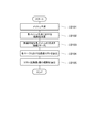
- the risk estimation device 20 of the driving support device 10 generates a mesh based on the yaw rate of the host vehicle detected by the host vehicle traveling state detection device 15 (S101).
- the risk level estimation device 20 calculates the risk level at each mesh intersection (S102).
- the risk level can be calculated by multiplying each information detected by the obstacle detection device 11 to the control mode switching SW 19 by a predetermined weighting coefficient and adding the information at each intersection of the meshes. .
- the target route generation device 30 connects each of the mesh intersections that the host vehicle can reach, and marks the route (S103).
- the target route generation device 30 calculates a passing cost, which is the sum of the risk levels of the mesh intersection points in each marked route, based on the risk levels of the mesh intersection points calculated by the risk level estimation device 20 (S104).
- the target route generation device 30 derives the route having the smallest calculated passing cost as the target route (S105).
- the driving support method determination device 40 is based on the display device 51, the sound device. 52 or the support device 53 is used to provide driving assistance necessary for the driver of the vehicle.
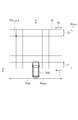
- a mesh M which is a grid-like region, is generated around the vehicle 100.
- X 0 [m] is an initial value of the length of the mesh generation region in the X-axis direction (front-rear direction of the own vehicle 100)
- Y 0 [m] is the Y-axis direction (left and right of the own vehicle 100).
- (Direction) is the initial value of the length of the mesh generation region.
- X FRONT [m] is the length of the mesh generation region that is finally generated in the positive direction of the X axis (in front of the vehicle 100).
- Y LEFT [m] and Y RIGHT [m] are the lengths of the mesh generation regions that are finally generated in the Y-axis left direction and Y-axis right direction, respectively, and the Y-axis left direction is positive.
- T [s] is the mesh generation time.
- v [m / s] is the vehicle speed of the host vehicle 100.
- ⁇ [rad / s] is the yaw rate of the vehicle 100, and the counterclockwise direction is positive.
- X 0 v ⁇ T.
- y (1/2)
- a y T 2 (1/2) v ⁇ T 2 (1)
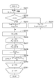
- the risk estimation device 20 of the driving support device 10 recognizes the vehicle speed v and the yaw rate ⁇ of the host vehicle 100 by the host vehicle traveling state detection device 15 (S201).
- the risk level estimation device 20 substitutes the above equation (1) to obtain the following equation (2).
- Y LEFT and Y RIGHT are calculated (S203).
- the region for generating the mesh M around the host vehicle 100 is calculated.
- the risk estimation device 20 calculates the coordinates of each intersection point of the mesh M divided into a grid.
- the division number N of the mesh M in the X direction is set as the division number M in the Y direction.
- the unit vector i in the X direction and the unit vector j in the Y direction of the smallest divided lattice area are used.
- the coordinates of the intersection point P of the mesh M that is i-th in the X direction and j-th in the Y direction from the origin O are P (x ij , y ij ).
- x ij (X FRONT / N) ⁇ i (4)
- the risk level estimation device 20 can change the region in which the mesh M is generated using the information from the vehicle running state detection device 15. For example, as the vehicle speed of the host vehicle 100 increases, the area of the mesh M in front of the host vehicle 100 is increased. As the acceleration of the host vehicle 100 increases, the area of the mesh M ahead of the host vehicle 100 is increased. As the deceleration of the host vehicle 100 increases, the area behind the host vehicle 100 of the mesh M is increased. The area of the mesh M in the direction indicated by the direction indicator on the side of the vehicle 100 is widened, and the area of the mesh M in the direction opposite to the direction indicated by the direction indicator on the side of the vehicle 100 is reduced.
- the risk estimation device 20 uses the information on the periphery of the vehicle 100 from the obstacle detection device 11, the white line detection device 12, the road shape detection device 13, the vehicle position detection device 16, and the surrounding environment database 17. It is possible to change the region for generating M.
- the periphery of the own vehicle 100 is divided into four directions of right front, left front, right rear, and left rear, and the mesh M is generated only in the area where the obstacle exists.
- the mesh M is generated only in the lane.
- the road shape is a curve
- the area of the mesh M in the direction in which the curve bends is widened.
- the area of the mesh M in the left-right direction of the host vehicle 100 is widened at the intersection.
- the area of the mesh M in the left-right direction of the own vehicle 100 is widened for the safety of pedestrians crossing the road. Moreover, about the direction which becomes a blind spot seeing from the own vehicle 100, the area
- the risk level estimation device 20 may change the region in which the mesh M is generated depending on the driver state detected by the driver state detection device 14 and the driver operation state detected by the driver operation state detection device 18. Is possible. For example, the area of the mesh M is widened as the driver's arousal level is low, and the area of the mesh M is narrowed as the driver's awakening level is high. Further, the region of the lateral mesh M on the side where the steering torque is generated is widened, and the region of the lateral mesh M on the side opposite to the side where the steering torque is generated is narrowed. Further, when the brake pedal is depressed, the area of the mesh M in the front direction is narrowed and the area of the mesh M in the rear direction is widened.
- the area of the mesh M in the forward direction is widened and the area of the mesh M in the backward direction is narrowed.
- the area of the mesh M in the face direction or line-of-sight direction of the driver is widened, and the area of the mesh M in the direction opposite to the face direction or line-of-sight direction of the driver is narrowed.
- the area of the mesh M in the direction of the driver's face or line of sight is narrowed, and the area of the mesh M in the direction opposite to the direction of the driver's face or line of sight is widened. Also good.
- the risk estimation device 20 can change the region for generating the mesh M according to the setting state of the control mode switching SW 19. For example, when the LKA or LDW setting is ON, the mesh M is generated only in the forward lane defined by the white line. When the setting for reducing damage from collision caused by ACC or PCS is ON, the area of the mesh M in front of and behind the host vehicle 100 is widened. When the setting of collision avoidance by PCS is ON, the area of the mesh M in all directions of the host vehicle 100 is widened. When the parking support system is set to ON, the area of the mesh M in all directions of the host vehicle 100 is narrowed.
- the division number N in the X direction and the division number M in the Y direction of the mesh M in the operation of FIG. 4 are changed according to the environment or state of the vehicle 100. Accordingly, the X-direction interval S X and the Y-direction interval S Y between the intersection points P of the mesh M may be changed.
- the risk level estimation device 20 can change the intervals S X and S Y of the intersection point P of the mesh M using the information from the own vehicle traveling state detection device 15. For example, as the vehicle speed of the host vehicle 100 increases, the distances S X and S Y between the intersection points P of the mesh M are increased.
- the division number N in the X direction of the mesh M and the division number M in the Y direction of the mesh M are expressed by the following equation (6) so that the intervals S X and S Y of the intersection point P of the mesh M are increased in proportion to the increase in the vehicle speed.
- the intervals S X and S Y of the intersection point P of M can be obtained by the following equation (7).
- N 0 is the minimum value of the division number N in the X direction of the mesh M
- M 0 is the minimum value of the division number M in the X direction of the mesh M
- ⁇ , ⁇ , ⁇ , and ⁇ are arbitrary constants. is there.
- S X X FRONT / [N 0 + ⁇ ( ⁇ / (v + ⁇ ) ⁇ ]
- S Y (Y RIGHT + Y LEFT ) / [M 0 + ⁇ ( ⁇ / (v + ⁇ ) ⁇ ] (7)
- the distance S Y intersection P of the yawing direction of the mesh M of the vehicle 100 is narrowed, the interval of the intersections of the opposite direction of the mesh M is the yawing direction of the vehicle 100 SY is widened.
- M LEFT the number of divisions of the mesh M in the Y-axis left direction
- M RIGHT the number of divisions of the mesh M in the Y-axis right direction
- the division is performed.
- the numbers M LEFT and M RIGHT can be obtained by the following equation (8).
- the interval S X between the intersection points P of the mesh M in front of the host vehicle 100 is narrowed, and the interval S X between the intersection points P of the mesh M behind the host vehicle 100 is increased.
- the greater the deceleration of the host vehicle 100 the narrower the distance S X between the intersection points P of the mesh M behind the host vehicle 100 and the wider the interval S X between the intersection points of the mesh M ahead of the host vehicle 100.
- Spacing S Y intersection P of the pointing direction of the mesh M of the turn signal is narrowed, the interval S Y intersection P in the opposite direction of the mesh M and pointing direction of the direction indicator is widely.
- the risk estimation device 20 uses the information on the periphery of the vehicle 100 from the obstacle detection device 11, the white line detection device 12, the road shape detection device 13, the vehicle position detection device 16, and the surrounding environment database 17. It is possible to change the intervals S X and S Y of the intersection point P of M.
- the periphery of the own vehicle 100 is divided into four directions, right front, left front, right rear, and left rear, and the intervals S X and S Y of the intersection point P of the mesh M in the area where the obstacle exists are narrowed.
- the intervals S X and S Y of the intersection point P of the mesh M in the lane are set as predetermined offset values, and the yawing direction of the own vehicle 100 according to the detected yaw rate of the own vehicle 100 is narrower spacing S Y intersection P of the mesh M is the yawing direction of the vehicle 100 spacing S Y intersection P in the opposite direction of the mesh M is widely.
- the distance S Y intersection P in the direction of the mesh M that curve bend is narrowed.
- the intersection, the interval S Y intersection P of the mesh M of the vehicle 100 left-right direction is narrow.
- the risk level estimation device 20 determines the intervals S X and S of the intersection points P of the mesh M depending on the driver state detected by the driver state detection device 14 and the driver operation state detected by the driver operation state detection device 18. It is possible to change Y. For example, the lower the driver's arousal level, the narrower the intervals S X and S Y of the mesh P, and the higher the driver's arousal level, the wider the intervals S X and S Y of the mesh M. . Further, a narrow gap S Y intersection P of the lateral mesh M on the side where the steering torque is generated is wider spacing S Y intersection P of the lateral mesh M in the opposite direction to the side where the steering torque is generated Is done.
- the interval S X of intersection P of the rear direction of the mesh M is narrow.
- the interval S X between the intersection points P of the mesh M in the forward direction is narrowed and the interval S X between the intersection points P of the mesh M in the rear direction is increased.
- the intervals S X and S Y of the mesh P in the direction in which the driver's face is facing are narrowed, and the interval S between the intersection points P of the mesh M in the direction opposite to the direction in which the driver's face is facing. X and SY are narrowed.
- the risk estimation device 20 can change the intervals S X and S Y of the intersection point P of the mesh M according to the setting state of the control mode switching SW 19. For example, when the LKA or LDW setting is ON, the intervals S X and S Y of the intersection point P of the mesh M in the forward lane defined by the white line are narrowed, and the intersection points of the mesh M in other regions The intervals S X and S Y of P are increased. When the setting for reducing the damage caused by collision due to ACC or PCS is ON, the distance S X between the intersection points P of the front and rear meshes M of the host vehicle 100 is narrowed, and the left and right meshes M of the host vehicle 100 are reduced. spacing S Y of the intersection P is widely.
- the intervals S X and S Y of the intersection point P of the mesh M in all directions of the own vehicle 100 are widened.
- the intervals S X and S Y of the intersection points P of the mesh M in all directions of the host vehicle 100 are narrowed.
- the risk degree estimation device 20 may increase the distances S X and S Y between the intersection points P of the mesh M as the distance from the host vehicle 100 increases. This is because the farther the distance, the lower the accuracy of recognition of each sensor, and the farther the distance, the higher the accuracy required for path recognition, so there is no need to set the intervals S X and S Y of the intersection points P of the fine mesh M.
- the information amount allocated to the risk information at each intersection P of the mesh M may be changed to change the accuracy of the information regarding the risk.
- the risk level estimation device 20 can change the amount of information allocated to the risk level information at the intersection point P of the mesh M using the information from the own vehicle traveling state detection device 15. For example, as the vehicle speed of the host vehicle 100 increases, the amount of information assigned to the risk information at the intersection point P of the mesh M is coarsened. When the yaw rate is generated in the own vehicle 100, the amount of information assigned to the risk information at the intersection point P of the mesh M in the yawing direction of the own vehicle 100 is made fine (high accuracy).
- the amount of information assigned to the risk information at the intersection P of the mesh M in front of the host vehicle 100 becomes finer, and the information assigned to the risk information at the intersection P of the mesh M behind the host vehicle 100.
- the amount is roughened.
- the amount of information assigned to the risk information at the intersection P of the mesh M in the direction indicated by the direction indicator is made fine, and the information amount assigned to the risk information at the intersection P of the mesh M in the direction opposite to the direction indicated by the direction indicator is determined. Roughened.
- the risk estimation device 20 uses the information on the periphery of the vehicle 100 from the obstacle detection device 11, the white line detection device 12, the road shape detection device 13, the vehicle position detection device 16, and the surrounding environment database 17. It is possible to change the information amount allocated to the risk information at the intersection P of M. For example, the area around the vehicle 100 is divided into four directions, right front, left front, right rear, and left rear, and the amount of information allocated to the risk information at the intersection P of the mesh M in the area where the obstacle is present is reduced. . Further, when the lane is recognized by the white line, only the information amount assigned to the risk information at the intersection P of the mesh M in the lane is made fine.
- the amount of information assigned to the risk information at the intersection P of the mesh M in the direction in which the curve bends is reduced, and the danger at the intersection P of the mesh M in the direction opposite to the direction in which the curve is bent.
- the amount of information allocated to the degree information is coarsened.
- the amount of information assigned to the risk information at the intersection P of the mesh M is made fine.
- the amount of information allocated to the risk information at the intersection P of the mesh M in the left-right direction of the host vehicle 100 is made finer for the safety of pedestrians crossing the road.
- the amount of information assigned to the risk information at the intersection P of the mesh M in the direction is made fine.
- the risk estimation device 20 uses the driver state detected by the driver state detection device 14 and the driver operation state detected by the driver operation state detection device 18 to display risk information at the intersection P of the mesh M. It is possible to change the amount of information to be allocated. For example, the lower the driver's arousal level, the smaller the amount of information assigned to the risk information at the intersection P of the mesh M. The higher the driver's arousal level, the more information amount assigned to the risk information at the intersection P of the mesh M. Is roughened.
- the amount of information assigned to the risk information at the intersection point P of the mesh M on the side where the steering torque is generated is made finer, and is assigned to the risk information at the intersection point P of the mesh M in the direction opposite to the side where the steering torque is generated.
- the amount of information is coarsened.
- the brake pedal is depressed, the information amount assigned to the risk information at the intersection P of the forward mesh M is coarsened, and the information amount assigned to the risk information at the intersection P of the rear mesh M is reduced. It is finely divided.
- the accelerator pedal is depressed, the amount of information assigned to the risk information at the intersection P of the forward mesh M is reduced, and the information amount assigned to the risk information at the intersection P of the backward mesh M. Is roughened.
- the amount of information assigned to the risk information at the intersection point P of the mesh M in the direction in which the driver's face is facing is made finer, and at the intersection point P of the mesh M in the direction opposite to the direction in which the driver's face is facing.
- the amount of information assigned to the risk information is coarsened.
- the information amount allocated to the risk information at the intersection point P of the mesh M in the driver's line-of-sight direction is made finer, and the information amount allocated to the risk information at the intersection point P of the mesh M in the direction opposite to the driver's line-of-sight direction is coarse. It will be lost.
- the amount of information assigned to the degree of danger information at the intersection P of the mesh M in the face direction or line-of-sight direction of the driver is roughened, which is opposite to the face direction or line-of-sight direction of the driver.
- the amount of information assigned to the risk information at the intersection P of the direction mesh M may be finely divided.
- the risk estimation device 20 can change the amount of information assigned to the risk information at the intersection P of the mesh M according to the setting state of the control mode switching SW 19. For example, when LKA or LDW is set to ON, only the amount of information assigned to the risk information at the intersection P of the mesh M in the forward lane divided by the white line is made fine, and the meshes in other areas The amount of information assigned to the risk information at the intersection P of M is made coarse. When the setting for reducing the damage caused by the collision due to ACC or PCS is ON, the amount of information assigned to the risk information at the intersection P of the mesh M forward and rearward of the host vehicle 100 is reduced. The amount of information assigned to the risk level information at the intersection point P of the mesh M in the left-right direction is roughened.
- the risk level estimation device 20 coarsens the amount of information assigned to the risk level information at the intersection point P of the mesh M as the accuracy of information required far from the host vehicle 100 becomes lower, and the risk level at each intersection point P. As the accuracy of information related to the vehicle 100 is lowered and the accuracy of information required close to the host vehicle 100 is increased, the amount of information assigned to the risk information at the intersection P of the mesh M is made finer. The accuracy of information may be increased.
- RVn (x, y) An ⁇ exp [( ⁇ 1/2 ⁇ ⁇ ((x ⁇ xn) / Sxn) 2 + ((y ⁇ yn) / Syn) 2 ⁇ ] (12)
- N number of vehicle obstacles
- Sxn x direction division of obstacle n ( ⁇ vxn (velocity x direction of obstacle n))
- Syn Division of obstacle n in y direction ( ⁇ vyn (speed of obstacle n in y direction))
- a risk function RL (x, y) indicating a risk level for the runway calculated from information on white lines, curbs, etc. in the area where the mesh M is set is expressed by the following equation (13).
- RL (x, y) B ⁇ (y ⁇ yl) 2 (13)
- the overall risk function R (x, y) indicating the overall risk in the area where the mesh M is set is expressed by the following equation (14).
- the risk level estimation device 20 calculates the risk level for the coordinates P (x, y) of each intersection point P by the following equation (14).
- R (x, y) ⁇ ⁇ RVn (x, y) ⁇ + RL (x, y) (14)
- the target route generation device 30 determines an intersection point P that is a target point of the host vehicle 100.
- the target route generation device 30 searches for a route having the minimum degree of risk according to the above equation (14) among routes from the current position to the target point.
- the target route generation device 30 can use a general Dijkstra method or a route search method based on the A * (Aster) method.
- the driving support method determination device 40 calculates the future predicted position (Xm, Ym) of the host vehicle 100 T seconds after the current speed v and yaw rate r of the host vehicle 100 using the following equation (15).
- the driving support method determination device 40 calculates the Y coordinate Yt of the target route ahead of Xm [m].
- the driving support method determination device 40 uses the display device 51 and the sound device 52 when the difference
- the driver is alerted and driving support by the support device 53 is started.
- the risk estimation device 20 of the driving support device 10 calculates the potential risk at a plurality of intersections P of the mesh M set around the host vehicle 100. Furthermore, the risk estimation device 20 changes the amount of information related to the potential risk calculated as the entire area of the mesh M in which the intersection point P is set, according to at least one of the environment and state of the host vehicle 100. For this reason, it becomes possible to calculate the potential risk around the host vehicle 100 according to the situation.
- the risk estimation device 20 changes the entire area of the mesh M in which the intersection point P is set by changing the area of the mesh M in which the intersection point P is set according to at least one of the environment and the state of the host vehicle 100. Since the amount of information related to the potential risk calculated as follows is changed, it is possible to calculate the potential risk around the host vehicle 100 in an area corresponding to the situation.
- the risk estimation device 20 changes the interval between the intersection points P of the mesh M according to at least one of the environment and the state of the host vehicle 100, so that the entire area of the mesh M in which the intersection point P is set. Since the amount of information regarding the potential risk to be calculated is changed, it is possible to calculate the potential risk around the host vehicle 100 with the density of the intersections P for calculating the potential risk according to the situation.
- the risk level estimation apparatus 20 changes the information amount regarding the potential risk level calculated for each intersection P of the mesh M according to at least one of the environment and the state of the host vehicle 100, the risk level estimation device 20 is more suitable for the situation. It is possible to calculate the potential risk around the vehicle 100 with the calculation load.
- the risk level estimation device 20 increases the information amount related to the potential risk level calculated in the traveling direction of the host vehicle 100 more than the information amount related to the potential risk level calculated outside the traveling direction of the host vehicle 100,
- the potential risk level in the traveling direction of the important vehicle 100 can be calculated with priority, and the potential risk level around the vehicle 100 is calculated with the distribution of information amount and the calculation load according to the situation. It becomes possible.
- the risk level estimation device 20 increases the information amount related to the potential risk calculated in the steering direction of the host vehicle 100 more than the information amount related to the potential risk calculated in other than the steering direction of the host vehicle 100.
- the potential danger level in the traveling direction of the host vehicle 100 can be calculated based on the steering direction that indicates the traveling direction of the host vehicle 100, and the amount of information and the calculation load can be calculated according to the situation. It is possible to calculate the potential risk around the own vehicle 100.
- the risk estimation device 20 uses the mesh M when the speed of the host vehicle 100 is higher than the information amount related to the potential risk calculated per unit area of the mesh M area when the speed of the host vehicle 100 is low. In order to reduce the amount of information related to the potential risk calculated per unit area of the area to be set, it is possible to eliminate the waste of calculating the detailed potential risk in a narrow area that is less important at high speeds. It is possible to calculate the potential risk around the host vehicle 100 with the distribution of the information amount according to the load and the calculation load.
- the risk level estimation device 20 calculates in the traveling direction of the host vehicle 100 rather than the amount of information related to the potential risk level calculated outside the traveling direction of the host vehicle 100.
- the risk level estimation device 20 calculates in the traveling direction of the host vehicle 100 rather than the amount of information related to the potential risk level calculated outside the traveling direction of the host vehicle 100.
- the risk level estimation device 20 is in a direction opposite to the traveling direction of the host vehicle 100 rather than the amount of information related to the potential risk level calculated in the traveling direction of the host vehicle 100.
- the potential risk in the direction opposite to the traveling direction of the own vehicle 100 which is more important at the time of deceleration, is emphasized before the speed of the own vehicle 100 is actually decelerated. It is possible to calculate, and it is possible to calculate the potential risk around the host vehicle 100 with the distribution of the information amount according to the situation and the calculation load.
- the risk level estimation device 20 uses the information about the potential risk level calculated in the direction opposite to the direction indicated by the direction indicator of the host vehicle 100.
- the potential in the direction of travel of the host vehicle 100 that is more important during steering before the direction of travel of the host vehicle 100 is actually changed. Therefore, it is possible to calculate the potential risk around the host vehicle 100 with more information amount distribution and calculation load according to the situation.
- the risk level estimation device 20 relates to the potential risk level calculated in the area that becomes the blind spot when viewed from the own vehicle 100 rather than the information amount related to the potential risk level calculated in areas other than the area that becomes the blind spot when viewed from the host vehicle 100.
- the risk level estimation device 20 In order to increase the amount of information, it is possible to focus on the potential risk level in the blind spot area as viewed from the more important vehicle 100, and to distribute the amount of information according to the situation and the load of computation. It is possible to calculate the potential risk around the car 100.
- the risk level estimation device 20 is other than either the face direction or the line-of-sight direction of the driver of the own vehicle 100, rather than the amount of information regarding the potential risk level calculated in either the face direction or the line-of-sight direction of the driver of the own vehicle 100.
- the potential risk in the direction opposite to the face direction or the line-of-sight direction of the driver of the vehicle 100 should be calculated more preferentially in situations where the risk level is high. It is possible to calculate intensively, and it is possible to calculate the potential risk around the host vehicle 100 with more information amount distribution and calculation load according to the situation.
- the risk level estimation device 20 calculates the potential risk level when the driver's awakening level of the host vehicle 100 is lower than the amount of information about the potential risk level calculated when the driver's awakening level of the host vehicle 100 is high. Therefore, the potential risk level can be calculated intensively in situations where the driver's arousal level is low and the risk level is high. It is possible to calculate the potential risk around the car 100.
- the target route generation device 30 generates the target route of the host vehicle 100 based on the potential risk levels at the plurality of intersections P of the mesh M calculated by the risk level estimation device 20. By driving the target route 100 generated based on the potential risk level, the potential risk can be reduced.
- the potential risk calculation device of the present invention it is possible to calculate the potential risk around the vehicle according to the situation.
Abstract
Description
y=(1/2)ayT2
=(1/2)vγT2 (1)
YLEFT=Y0+(1/2)vγT2
YRIGHT=-Y0 (2)
YLEFT=Y0
YRIGHT=-Y0+(1/2)vγT2 (3)
xij=(XFRONT/N)×i (4)
yij=YLEFT+{(|YRIGHT|+|YLEFT|)/M}×j (5)
N=N0+{(α/(v+β)}
M=M0+{(γ/(v+δ)} (6)
SX=XFRONT/[N0+{(α/(v+β)}]
SY=(YRIGHT+YLEFT)/[M0+{(γ/(v+δ)}] (7)
MLEFT=vr+(M0/2)
MRIGHT=M0/2 (8)
MLEFT=M0/2
MRIGHT=-vr+(M0/2) (9)
自車100が左側に旋回しているときは(r≧0)、間隔SYLEFT,SYRIGHTはそれぞれ下式(10)により求めることができ、自車100が右側に旋回しているときは(r<0)、間隔SYLEFT,SYRIGHTはそれぞれ下式(11)により求めることができる。
SYLEFT=YLEFT/{vr+(M0/2)}
SYRIGHT=YRIGHT/(M0/2) (10)
SYLEFT=YLEFT/(M0/2)
SYRIGHT=YRIGHT/{-vr+(M0/2)} (11)
RVn(x,y)=An×exp[(-1/2×{((x-xn)/Sxn)2+((y-yn)/Syn)2}] (12)
N:車両障害物数
An:係数
xn:障害物nのx座標位置
yn:障害物nのy座標位置
Sxn:障害物nのx方向分算(∝vxn(障害物nのx方向速度))
Syn:障害物nのy方向分算(∝vyn(障害物nのy方向速度))
RL(x,y)=B×(y-yl)2 (13)
B:係数
yl:走路中央のy座標
R(x,y)=Σ{RVn(x,y)}+RL(x,y) (14)

11 障害物検出装置
12 白線検出装置
13 道路形状検出装置
14 ドライバ状態検出装置
15 自車走行状況検出装置
16 自車位置検出装置
17 周辺環境データベース
18 ドライバ操作状態検出装置
19 制御モード切替SW
20 危険度推定装置
30 目標経路生成装置
40 運転支援方法判断装置
51 表示装置
52 音声装置
53 支援装置
100 自車
Claims (15)
- 自車の周辺に設定された複数の地点における危険度を算出する危険度算出ユニットを備え、前記危険度算出ユニットは、前記自車の環境及び状態の少なくともいずれかに応じて、前記地点が設定された領域全体として算出する前記危険度に関する情報量を変化させる、危険度算出装置。
- 前記危険度算出ユニットは、前記自車の環境及び状態の少なくともいずれかに応じて、前記地点を設定する領域を変化させることにより、前記地点が設定された領域全体として算出する前記危険度に関する情報量を変化させる、請求項1に記載の危険度算出装置。
- 前記危険度算出ユニットは、前記自車の環境及び状態の少なくともいずれかに応じて、前記地点同士の間隔を変化させることにより、前記地点が設定された領域全体として算出する前記危険度に関する情報量を変化させる、請求項1又は2に記載の危険度算出装置。
- 前記危険度算出ユニットは、前記自車の環境及び状態の少なくともいずれかに応じて、前記地点ごとに算出する前記危険度に関する情報量を変化させることにより、前記地点が設定された領域全体として算出する前記危険度に関する情報量を変化させる、請求項1~3のいずれか1項に記載の危険度算出装置。
- 前記危険度算出ユニットは、前記自車の進行方向以外において算出する前記危険度に関する情報量よりも前記自車の進行方向において算出する前記危険度に関する情報量を多くする、請求項1~4のいずれか1項に記載の危険度算出装置。
- 前記危険度算出ユニットは、前記自車の操舵方向以外において算出する前記危険度に関する情報量よりも前記自車の操舵方向において算出する前記危険度に関する情報量を多くする、請求項5に記載の危険度算出装置。
- 前記危険度算出ユニットは、前記自車の速度が低いときに前記地点を設定する領域の単位面積当りに算出する前記危険度に関する情報量よりも前記自車の速度が高いときに前記地点を設定する領域の単位面積当りに算出する前記危険度に関する情報量を少なくする、請求項1~6のいずれか1項に記載の危険度算出装置。
- 前記危険度算出ユニットは、前記自車のアクセルペダルが踏まれているときには、前記自車の進行方向以外において算出する前記危険度に関する情報量よりも前記自車の進行方向において算出する前記危険度に関する情報量を多くする、請求項1~7のいずれか1項に記載の危険度算出装置。
- 前記危険度算出ユニットは、前記自車のブレーキペダルが踏まれているときには、前記自車の進行方向において算出する前記危険度に関する情報量よりも前記自車の進行方向と反対方向において算出する前記危険度に関する情報量を多くする、請求項1~8のいずれか1項に記載の危険度算出装置。
- 前記危険度算出ユニットは、前記自車の方向指示器が操作されているときには、前記自車の方向指示器の指示方向と反対方向において算出する前記危険度に関する情報量よりも前記自車の方向指示器の指示方向において算出する前記危険度に関する情報量を多くする、請求項1~9のいずれか1項に記載の危険度算出装置。
- 前記危険度算出ユニットは、前記自車から見て死角となる領域以外において算出する前記危険度に関する情報量よりも前記自車から見て死角となる領域において算出する前記危険度に関する情報量を多くする、請求項1~10のいずれか1項に記載の危険度算出装置。
- 前記危険度算出ユニットは、前記自車のドライバーの顔向き及び視線方向のいずれか以外において算出する前記危険度に関する情報量よりも前記自車のドライバーの顔向き及び視線方向のいずれかにおいて算出する前記危険度に関する情報量を多くする、請求項1~11のいずれか1項に記載の危険度算出装置。
- 前記危険度算出ユニットは、前記自車のドライバーの顔向き及び視線方向のいずれかにおいて算出する前記危険度に関する情報量よりも前記自車のドライバーの顔向き及び視線方向のいずれか以外において算出する前記危険度に関する情報量を多くする、請求項1~11のいずれか1項に記載の危険度算出装置。
- 前記危険度算出ユニットは、前記自車のドライバーの覚醒度が高いときに算出する前記危険度に関する情報量よりも前記自車のドライバーの覚醒度が低いときに算出する前記危険度に関する情報量を多くする、請求項1~13のいずれか1項に記載の危険度算出装置。
- 前記危険度算出ユニットが算出した複数の前記地点における前記危険度に基づいて前記自車の目標経路を生成する目標経路生成ユニットをさらに備えた、請求項1~14のいずれか1項に記載の危険度算出装置。
Priority Applications (5)
| Application Number | Priority Date | Filing Date | Title |
|---|---|---|---|
| EP10846124.5A EP2541524B1 (en) | 2010-02-22 | 2010-02-22 | Risk degree calculation device |
| CN201080064421.0A CN102763146B (zh) | 2010-02-22 | 2010-02-22 | 危险度计算装置 |
| JP2012500439A JP5382198B2 (ja) | 2010-02-22 | 2010-02-22 | 危険度算出装置 |
| US13/580,304 US9135825B2 (en) | 2010-02-22 | 2010-02-22 | Risk degree calculation device |
| PCT/JP2010/052634 WO2011101988A1 (ja) | 2010-02-22 | 2010-02-22 | 危険度算出装置 |
Applications Claiming Priority (1)
| Application Number | Priority Date | Filing Date | Title |
|---|---|---|---|
| PCT/JP2010/052634 WO2011101988A1 (ja) | 2010-02-22 | 2010-02-22 | 危険度算出装置 |
Publications (1)
| Publication Number | Publication Date |
|---|---|
| WO2011101988A1 true WO2011101988A1 (ja) | 2011-08-25 |
Family
ID=44482605
Family Applications (1)
| Application Number | Title | Priority Date | Filing Date |
|---|---|---|---|
| PCT/JP2010/052634 WO2011101988A1 (ja) | 2010-02-22 | 2010-02-22 | 危険度算出装置 |
Country Status (5)
| Country | Link |
|---|---|
| US (1) | US9135825B2 (ja) |
| EP (1) | EP2541524B1 (ja) |
| JP (1) | JP5382198B2 (ja) |
| CN (1) | CN102763146B (ja) |
| WO (1) | WO2011101988A1 (ja) |
Cited By (17)
| Publication number | Priority date | Publication date | Assignee | Title |
|---|---|---|---|---|
| JP2013196032A (ja) * | 2012-03-15 | 2013-09-30 | Toyota Motor Corp | 運転支援装置 |
| JP2015032179A (ja) * | 2013-08-05 | 2015-02-16 | 富士重工業株式会社 | 車外環境認識装置 |
| JP2015519642A (ja) * | 2012-04-26 | 2015-07-09 | コンティネンタル・テーベス・アクチエンゲゼルシヤフト・ウント・コンパニー・オッフェネ・ハンデルスゲゼルシヤフト | 車両周辺部を描写するための方法 |
| CN105264586A (zh) * | 2013-06-03 | 2016-01-20 | 罗伯特·博世有限公司 | 用于车辆的占用地图 |
| JP2016136378A (ja) * | 2015-01-23 | 2016-07-28 | ホンダ リサーチ インスティテュート ヨーロッパ ゲーエムベーハーHonda Research Institute Europe GmbH | 自己の乗り物のドライバを支援する方法およびシステム |
| WO2016170646A1 (ja) * | 2015-04-23 | 2016-10-27 | 日産自動車株式会社 | シーン理解装置 |
| JPWO2017022475A1 (ja) * | 2015-07-31 | 2018-02-08 | 日立オートモティブシステムズ株式会社 | 自車周辺情報管理装置 |
| JP2018084972A (ja) * | 2016-11-24 | 2018-05-31 | 株式会社デンソー | 車両軌道用グラフ生成装置 |
| JP2018138406A (ja) * | 2017-02-24 | 2018-09-06 | マツダ株式会社 | 車両運転支援システム及び方法 |
| JP2018139030A (ja) * | 2017-02-24 | 2018-09-06 | マツダ株式会社 | 車両運転支援システム及び方法 |
| JP2018138407A (ja) * | 2017-02-24 | 2018-09-06 | マツダ株式会社 | 車両運転支援システム及び方法 |
| JP2018138403A (ja) * | 2017-02-24 | 2018-09-06 | マツダ株式会社 | 車両運転支援システム及び方法 |
| WO2018198769A1 (ja) * | 2017-04-26 | 2018-11-01 | 日立オートモティブシステムズ株式会社 | 周辺環境認識装置、表示制御装置 |
| JP2020163975A (ja) * | 2019-03-29 | 2020-10-08 | マツダ株式会社 | 車両運転支援システム |
| CN111803065A (zh) * | 2020-06-23 | 2020-10-23 | 北方工业大学 | 一种基于脑电数据的危险交通场景辨识方法及系统 |
| WO2020226085A1 (ja) * | 2019-05-09 | 2020-11-12 | ソニー株式会社 | 情報処理装置、情報処理方法、及びプログラム |
| US10921143B2 (en) | 2017-06-20 | 2021-02-16 | Kabushiki Kaisha Toshiba | Information processing device, mobile object, information processing method, and computer program product |
Families Citing this family (28)
| Publication number | Priority date | Publication date | Assignee | Title |
|---|---|---|---|---|
| JP5706874B2 (ja) * | 2010-03-03 | 2015-04-22 | 本田技研工業株式会社 | 車両の周辺監視装置 |
| JP5403152B2 (ja) * | 2010-05-10 | 2014-01-29 | トヨタ自動車株式会社 | 危険度算出装置 |
| US9058247B2 (en) * | 2010-09-08 | 2015-06-16 | Toyota Jidosha Kabushiki Kaisha | Risk potential calculation apparatus |
| US9415774B2 (en) * | 2011-09-22 | 2016-08-16 | Nissan Motor Co., Ltd. | Vehicle control apparatus including an obstacle detection device |
| US9050980B2 (en) * | 2013-02-25 | 2015-06-09 | Honda Motor Co., Ltd. | Real time risk assessment for advanced driver assist system |
| US9342986B2 (en) * | 2013-02-25 | 2016-05-17 | Honda Motor Co., Ltd. | Vehicle state prediction in real time risk assessments |
| KR101736306B1 (ko) | 2013-02-27 | 2017-05-29 | 한국전자통신연구원 | 차량과 운전자간 협력형 자율 주행 장치 및 방법 |
| CN103428475A (zh) * | 2013-07-24 | 2013-12-04 | 佳都新太科技股份有限公司 | 一种基于警车gps定位和摄像机视频实现gis虚拟巡逻的方法 |
| US9786178B1 (en) * | 2013-08-02 | 2017-10-10 | Honda Motor Co., Ltd. | Vehicle pedestrian safety system and methods of use and manufacture thereof |
| JP6429368B2 (ja) | 2013-08-02 | 2018-11-28 | 本田技研工業株式会社 | 歩車間通信システムおよび方法 |
| KR101480647B1 (ko) * | 2013-11-15 | 2015-01-09 | 현대자동차주식회사 | 협로 주행을 위한 조향 위험도 판단 시스템 및 그 판단 방법 |
| WO2015146083A1 (ja) * | 2014-03-28 | 2015-10-01 | 日本電気株式会社 | 情報収集装置、情報収集方法、及び、プログラムの記録媒体 |
| JP6128059B2 (ja) * | 2014-05-30 | 2017-05-17 | 株式会社デンソー | 退避走行支援装置 |
| EP2963632A1 (en) * | 2014-07-03 | 2016-01-06 | Application Solutions (Electronics and Vision) Limited | Manoeuvre assistance |
| JP6055865B2 (ja) * | 2014-08-04 | 2016-12-27 | 富士重工業株式会社 | 走行環境危険度判定装置および走行環境危険度報知装置 |
| JP6391536B2 (ja) * | 2015-06-12 | 2018-09-19 | 日立建機株式会社 | 車載装置、車両衝突防止方法 |
| US10525984B2 (en) * | 2016-08-19 | 2020-01-07 | Massachusetts Institute Of Technology | Systems and methods for using an attention buffer to improve resource allocation management |
| JP6323511B2 (ja) * | 2016-08-26 | 2018-05-16 | マツダ株式会社 | 運転者体調検知装置及び方法 |
| JP6654544B2 (ja) * | 2016-10-21 | 2020-02-26 | 株式会社Soken | センサ制御装置 |
| US10421459B2 (en) | 2016-12-20 | 2019-09-24 | GM Global Technology Operations LLC | Contextual-assessment vehicle systems |
| JP6686865B2 (ja) * | 2016-12-21 | 2020-04-22 | オムロン株式会社 | 運転状態判定装置 |
| JP2018138405A (ja) * | 2017-02-24 | 2018-09-06 | マツダ株式会社 | 車両運転支援システム及び方法 |
| JP6678609B2 (ja) * | 2017-03-01 | 2020-04-08 | 株式会社東芝 | 情報処理装置、情報処理方法、情報処理プログラム、および移動体 |
| US11059421B2 (en) | 2018-03-29 | 2021-07-13 | Honda Motor Co., Ltd. | Vehicle proximity system using heads-up display augmented reality graphics elements |
| JP7043376B2 (ja) * | 2018-09-18 | 2022-03-29 | 株式会社東芝 | 情報処理装置、車両制御装置および移動体制御方法 |
| JP7052709B2 (ja) * | 2018-12-25 | 2022-04-12 | トヨタ自動車株式会社 | 車両制御装置及び車両制御方法 |
| CN112781592A (zh) * | 2019-11-11 | 2021-05-11 | 南京航空航天大学 | 一种低空物流无人机路径规划方法及系统 |
| CN115257728B (zh) * | 2022-10-08 | 2022-12-23 | 杭州速玛科技有限公司 | 一种用于自动驾驶的盲区风险区检测方法 |
Citations (4)
| Publication number | Priority date | Publication date | Assignee | Title |
|---|---|---|---|---|
| JP2005043375A (ja) * | 2004-09-03 | 2005-02-17 | Mitsubishi Electric Corp | 車両周辺監視装置 |
| JP2006154967A (ja) | 2004-11-25 | 2006-06-15 | Nissan Motor Co Ltd | リスク最小軌跡生成装置およびこれを用いた危険状況警報装置 |
| JP2006350699A (ja) * | 2005-06-16 | 2006-12-28 | Nissan Motor Co Ltd | 画像処理装置及び方法 |
| JP2010003254A (ja) * | 2008-06-23 | 2010-01-07 | Hitachi Ltd | 画像処理装置 |
Family Cites Families (14)
| Publication number | Priority date | Publication date | Assignee | Title |
|---|---|---|---|---|
| US5347459A (en) * | 1993-03-17 | 1994-09-13 | National Research Council Of Canada | Real time collision detection |
| JP3645177B2 (ja) * | 2000-11-29 | 2005-05-11 | 三菱電機株式会社 | 車両周辺監視装置 |
| JP2002352399A (ja) * | 2001-05-23 | 2002-12-06 | Mitsubishi Electric Corp | 車両周辺監視装置 |
| US6859144B2 (en) * | 2003-02-05 | 2005-02-22 | Delphi Technologies, Inc. | Vehicle situation alert system with eye gaze controlled alert signal generation |
| JP4402400B2 (ja) * | 2003-08-28 | 2010-01-20 | オリンパス株式会社 | 物体認識装置 |
| US7541974B2 (en) * | 2005-12-15 | 2009-06-02 | Trimble Navigation Limited | Managed traverse system and method to acquire accurate survey data in absence of precise GPS data |
| JP4759547B2 (ja) * | 2007-09-27 | 2011-08-31 | 日立オートモティブシステムズ株式会社 | 走行支援装置 |
| JP4929114B2 (ja) * | 2007-09-28 | 2012-05-09 | 日産自動車株式会社 | 車両用情報報知装置、情報提供システム、情報報知方法 |
| CA2742126A1 (en) * | 2007-10-30 | 2009-05-07 | Allen E. Webster | Vehicle safety camera system |
| JP5082834B2 (ja) * | 2007-12-27 | 2012-11-28 | オムロン株式会社 | 脇見検出装置および方法、並びに、プログラム |
| WO2009101687A1 (ja) * | 2008-02-14 | 2009-08-20 | Konica Minolta Holdings, Inc. | 測距装置 |
| WO2010129907A2 (en) * | 2009-05-08 | 2010-11-11 | Scientific Systems Company Inc. | Method and system for visual collision detection and estimation |
| TW201100280A (en) * | 2009-06-19 | 2011-01-01 | Automotive Res & Testing Ct | Collision warning system for vehicle |
| JP5206752B2 (ja) * | 2010-08-30 | 2013-06-12 | 株式会社デンソー | 走行環境認識装置 |
-
2010
- 2010-02-22 CN CN201080064421.0A patent/CN102763146B/zh active Active
- 2010-02-22 WO PCT/JP2010/052634 patent/WO2011101988A1/ja active Application Filing
- 2010-02-22 JP JP2012500439A patent/JP5382198B2/ja active Active
- 2010-02-22 EP EP10846124.5A patent/EP2541524B1/en active Active
- 2010-02-22 US US13/580,304 patent/US9135825B2/en active Active
Patent Citations (4)
| Publication number | Priority date | Publication date | Assignee | Title |
|---|---|---|---|---|
| JP2005043375A (ja) * | 2004-09-03 | 2005-02-17 | Mitsubishi Electric Corp | 車両周辺監視装置 |
| JP2006154967A (ja) | 2004-11-25 | 2006-06-15 | Nissan Motor Co Ltd | リスク最小軌跡生成装置およびこれを用いた危険状況警報装置 |
| JP2006350699A (ja) * | 2005-06-16 | 2006-12-28 | Nissan Motor Co Ltd | 画像処理装置及び方法 |
| JP2010003254A (ja) * | 2008-06-23 | 2010-01-07 | Hitachi Ltd | 画像処理装置 |
Non-Patent Citations (1)
| Title |
|---|
| See also references of EP2541524A4 |
Cited By (32)
| Publication number | Priority date | Publication date | Assignee | Title |
|---|---|---|---|---|
| JP2013196032A (ja) * | 2012-03-15 | 2013-09-30 | Toyota Motor Corp | 運転支援装置 |
| JP2015519642A (ja) * | 2012-04-26 | 2015-07-09 | コンティネンタル・テーベス・アクチエンゲゼルシヤフト・ウント・コンパニー・オッフェネ・ハンデルスゲゼルシヤフト | 車両周辺部を描写するための方法 |
| US9896092B2 (en) | 2012-04-26 | 2018-02-20 | Continental Teves Ag & Co. Ohg | Method for representing vehicle surroundings |
| CN105264586A (zh) * | 2013-06-03 | 2016-01-20 | 罗伯特·博世有限公司 | 用于车辆的占用地图 |
| JP2016522508A (ja) * | 2013-06-03 | 2016-07-28 | ローベルト ボツシユ ゲゼルシヤフト ミツト ベシユレンクテル ハフツングRobert Bosch Gmbh | 車両用占有グリッドマップ |
| US9823661B2 (en) | 2013-06-03 | 2017-11-21 | Robert Bosch Gmbh | Occupancy grid map for a vehicle |
| JP2015032179A (ja) * | 2013-08-05 | 2015-02-16 | 富士重工業株式会社 | 車外環境認識装置 |
| US9978276B2 (en) | 2013-08-05 | 2018-05-22 | Subaru Corporation | Vehicle exterior environment recognition device |
| JP2016136378A (ja) * | 2015-01-23 | 2016-07-28 | ホンダ リサーチ インスティテュート ヨーロッパ ゲーエムベーハーHonda Research Institute Europe GmbH | 自己の乗り物のドライバを支援する方法およびシステム |
| WO2016170646A1 (ja) * | 2015-04-23 | 2016-10-27 | 日産自動車株式会社 | シーン理解装置 |
| US10262215B2 (en) | 2015-04-23 | 2019-04-16 | Nissan Motor Co., Ltd. | Scene understanding device |
| JPWO2016170646A1 (ja) * | 2015-04-23 | 2018-04-05 | 日産自動車株式会社 | シーン理解装置 |
| JPWO2017022475A1 (ja) * | 2015-07-31 | 2018-02-08 | 日立オートモティブシステムズ株式会社 | 自車周辺情報管理装置 |
| CN108352116A (zh) * | 2015-07-31 | 2018-07-31 | 日立汽车系统株式会社 | 自身车辆周边信息管理装置 |
| CN108352116B (zh) * | 2015-07-31 | 2022-04-05 | 日立安斯泰莫株式会社 | 自身车辆周边信息管理装置 |
| US10759336B2 (en) | 2015-07-31 | 2020-09-01 | Hitachi Automotive Systems, Ltd. | Vehicle periphery information management device |
| JP2019215893A (ja) * | 2015-07-31 | 2019-12-19 | 日立オートモティブシステムズ株式会社 | 自車周辺情報管理装置 |
| US10493907B2 (en) | 2015-07-31 | 2019-12-03 | Hitachi Automotive Systems, Ltd. | Vehicle periphery information management device |
| JP2018084972A (ja) * | 2016-11-24 | 2018-05-31 | 株式会社デンソー | 車両軌道用グラフ生成装置 |
| JP2018138407A (ja) * | 2017-02-24 | 2018-09-06 | マツダ株式会社 | 車両運転支援システム及び方法 |
| JP2018138403A (ja) * | 2017-02-24 | 2018-09-06 | マツダ株式会社 | 車両運転支援システム及び方法 |
| JP2018139030A (ja) * | 2017-02-24 | 2018-09-06 | マツダ株式会社 | 車両運転支援システム及び方法 |
| JP2018138406A (ja) * | 2017-02-24 | 2018-09-06 | マツダ株式会社 | 車両運転支援システム及び方法 |
| JP2018185668A (ja) * | 2017-04-26 | 2018-11-22 | 日立オートモティブシステムズ株式会社 | 周辺環境認識装置、表示制御装置 |
| WO2018198769A1 (ja) * | 2017-04-26 | 2018-11-01 | 日立オートモティブシステムズ株式会社 | 周辺環境認識装置、表示制御装置 |
| US10921143B2 (en) | 2017-06-20 | 2021-02-16 | Kabushiki Kaisha Toshiba | Information processing device, mobile object, information processing method, and computer program product |
| JP2020163975A (ja) * | 2019-03-29 | 2020-10-08 | マツダ株式会社 | 車両運転支援システム |
| JP7252513B2 (ja) | 2019-03-29 | 2023-04-05 | マツダ株式会社 | 車両運転支援システム |
| WO2020226085A1 (ja) * | 2019-05-09 | 2020-11-12 | ソニー株式会社 | 情報処理装置、情報処理方法、及びプログラム |
| CN113785253A (zh) * | 2019-05-09 | 2021-12-10 | 索尼集团公司 | 信息处理装置、信息处理方法和程序 |
| CN111803065A (zh) * | 2020-06-23 | 2020-10-23 | 北方工业大学 | 一种基于脑电数据的危险交通场景辨识方法及系统 |
| CN111803065B (zh) * | 2020-06-23 | 2023-12-26 | 北方工业大学 | 一种基于脑电数据的危险交通场景辨识方法及系统 |
Also Published As
| Publication number | Publication date |
|---|---|
| JP5382198B2 (ja) | 2014-01-08 |
| EP2541524A1 (en) | 2013-01-02 |
| CN102763146B (zh) | 2015-02-11 |
| EP2541524A4 (en) | 2017-01-11 |
| US9135825B2 (en) | 2015-09-15 |
| EP2541524B1 (en) | 2018-04-25 |
| JPWO2011101988A1 (ja) | 2013-06-17 |
| CN102763146A (zh) | 2012-10-31 |
| US20120323479A1 (en) | 2012-12-20 |
Similar Documents
| Publication | Publication Date | Title |
|---|---|---|
| JP5382198B2 (ja) | 危険度算出装置 | |
| JP5454695B2 (ja) | 危険度算出装置 | |
| CN111052733B (zh) | 周围车辆显示方法及周围车辆显示装置 | |
| JP5094658B2 (ja) | 走行環境認識装置 | |
| JP5075152B2 (ja) | 車両制御装置 | |
| JP5004865B2 (ja) | 自動車用障害物検知装置 | |
| JP5641146B2 (ja) | 運転支援装置及び運転支援方法 | |
| EP2560151B1 (en) | Driving support device | |
| JP5410730B2 (ja) | 自動車の外界認識装置 | |
| JP6461042B2 (ja) | 運転支援装置 | |
| WO2018020547A1 (ja) | 車線変更支援方法および車線変更支援装置 | |
| CN110254421A (zh) | 驾驶辅助系统 | |
| JP2011118570A (ja) | 車両の衝突を回避するための装置 | |
| JP5521575B2 (ja) | 車両接近報知装置 | |
| JP2010140186A (ja) | 経路推定装置及び運転支援装置 | |
| JP2011118723A (ja) | 車両の衝突を回避するための装置 | |
| JP2017194930A (ja) | 移動体の自動運転制御システム | |
| US20220024462A1 (en) | Control device for vehicle, control method for automated driven vehicle, and nontransitory recording medium provided with computer program | |
| JP5343821B2 (ja) | 車両制御装置 | |
| JP2011113239A (ja) | 車両の衝突を回避するための装置 |
Legal Events
| Date | Code | Title | Description |
|---|---|---|---|
| WWE | Wipo information: entry into national phase |
Ref document number: 201080064421.0 Country of ref document: CN |
|
| 121 | Ep: the epo has been informed by wipo that ep was designated in this application |
Ref document number: 10846124 Country of ref document: EP Kind code of ref document: A1 |
|
| WWE | Wipo information: entry into national phase |
Ref document number: 2012500439 Country of ref document: JP |
|
| WWE | Wipo information: entry into national phase |
Ref document number: 13580304 Country of ref document: US |
|
| NENP | Non-entry into the national phase |
Ref country code: DE |
|
| WWE | Wipo information: entry into national phase |
Ref document number: 2010846124 Country of ref document: EP |