WO2011033976A1 - 反射防止部材、およびその製造方法 - Google Patents
反射防止部材、およびその製造方法 Download PDFInfo
- Publication number
- WO2011033976A1 WO2011033976A1 PCT/JP2010/065411 JP2010065411W WO2011033976A1 WO 2011033976 A1 WO2011033976 A1 WO 2011033976A1 JP 2010065411 W JP2010065411 W JP 2010065411W WO 2011033976 A1 WO2011033976 A1 WO 2011033976A1
- Authority
- WO
- WIPO (PCT)
- Prior art keywords
- layer
- mass
- antireflection
- coating composition
- refractive index
- Prior art date
- Legal status (The legal status is an assumption and is not a legal conclusion. Google has not performed a legal analysis and makes no representation as to the accuracy of the status listed.)
- Ceased
Links
Images


Classifications
-
- G—PHYSICS
- G02—OPTICS
- G02B—OPTICAL ELEMENTS, SYSTEMS OR APPARATUS
- G02B1/00—Optical elements characterised by the material of which they are made; Optical coatings for optical elements
- G02B1/10—Optical coatings produced by application to, or surface treatment of, optical elements
- G02B1/11—Anti-reflection coatings
- G02B1/111—Anti-reflection coatings using layers comprising organic materials
-
- B—PERFORMING OPERATIONS; TRANSPORTING
- B32—LAYERED PRODUCTS
- B32B—LAYERED PRODUCTS, i.e. PRODUCTS BUILT-UP OF STRATA OF FLAT OR NON-FLAT, e.g. CELLULAR OR HONEYCOMB, FORM
- B32B5/00—Layered products characterised by the non- homogeneity or physical structure, i.e. comprising a fibrous, filamentary, particulate or foam layer; Layered products characterised by having a layer differing constitutionally or physically in different parts
- B32B5/22—Layered products characterised by the non- homogeneity or physical structure, i.e. comprising a fibrous, filamentary, particulate or foam layer; Layered products characterised by having a layer differing constitutionally or physically in different parts characterised by the presence of two or more layers which are next to each other and are fibrous, filamentary, formed of particles or foamed
- B32B5/30—Layered products characterised by the non- homogeneity or physical structure, i.e. comprising a fibrous, filamentary, particulate or foam layer; Layered products characterised by having a layer differing constitutionally or physically in different parts characterised by the presence of two or more layers which are next to each other and are fibrous, filamentary, formed of particles or foamed one layer being formed of particles, e.g. chips, granules, powder
-
- G—PHYSICS
- G02—OPTICS
- G02B—OPTICAL ELEMENTS, SYSTEMS OR APPARATUS
- G02B1/00—Optical elements characterised by the material of which they are made; Optical coatings for optical elements
- G02B1/10—Optical coatings produced by application to, or surface treatment of, optical elements
- G02B1/11—Anti-reflection coatings
- G02B1/113—Anti-reflection coatings using inorganic layer materials only
- G02B1/115—Multilayers
-
- B—PERFORMING OPERATIONS; TRANSPORTING
- B32—LAYERED PRODUCTS
- B32B—LAYERED PRODUCTS, i.e. PRODUCTS BUILT-UP OF STRATA OF FLAT OR NON-FLAT, e.g. CELLULAR OR HONEYCOMB, FORM
- B32B2260/00—Layered product comprising an impregnated, embedded, or bonded layer wherein the layer comprises an impregnation, embedding, or binder material
- B32B2260/02—Composition of the impregnated, bonded or embedded layer
- B32B2260/025—Particulate layer
-
- G—PHYSICS
- G02—OPTICS
- G02B—OPTICAL ELEMENTS, SYSTEMS OR APPARATUS
- G02B2207/00—Coding scheme for general features or characteristics of optical elements and systems of subclass G02B, but not including elements and systems which would be classified in G02B6/00 and subgroups
- G02B2207/107—Porous materials, e.g. for reducing the refractive index
-
- G—PHYSICS
- G02—OPTICS
- G02B—OPTICAL ELEMENTS, SYSTEMS OR APPARATUS
- G02B2207/00—Coding scheme for general features or characteristics of optical elements and systems of subclass G02B, but not including elements and systems which would be classified in G02B6/00 and subgroups
- G02B2207/109—Sols, gels, sol-gel materials
Definitions
- the present invention relates to an antireflection member and a method for manufacturing the antireflection member.
- An antireflection member typified by an antireflection film is disposed on the outermost surface of an image display device such as a cathode ray tube display (CRT), a plasma display panel (PDP), or a liquid crystal display (LCD).
- the antireflection member reduces the reflectivity by using the principle of optical interference in order to prevent contrast degradation and image reflection due to reflection of external light.
- antireflection members have been proposed as antireflection members with improved scratch resistance and wear resistance.
- An antireflection film has been proposed (Patent Document 1).
- the resin composition constituting the hard coat layer has a mass average molecular weight of at least one resin of 8000 to 150,000 (Patent Document 2).
- a method of forming an antireflection layer by coating a coating composition in which low refractive index fine particles and medium or high refractive index fine particles are dispersed in a binder resin is proposed.
- silica fine particles treated with a fluorine compound are used as the low refractive index fine particles. Due to the difference in specific gravity, many low refractive index fine particles exist in the upper part or middle part of the antireflection layer, and many middle or high refractive index fine particles exist in the middle part or lower part (Patent Document 3).
- This coating composition contains two or more types of inorganic particles and a metal chelate compound, and is characterized in that at least one type of inorganic particles is an inorganic particle whose surface is treated with a fluorine compound (Patent Document 4).
- antireflection members have been proposed as focusing on the function of the interlayer interface of the layers constituting the antireflection member.
- the first transparent layer and the second transparent layer are adjacent to each other, and the first transparent layer and the second transparent layer have different refractive indexes, and the contact interface between the first transparent layer and the second transparent layer
- An optical film having a light scattering interface has been proposed.
- the contact interface between the first transparent layer and the second transparent layer is a light scattering interface, the generation of interference fringes is suppressed and an optical film is obtained (Patent Document 5).
- An antireflection film has been proposed in which a transparent conductive layer, a high refractive index hard coat layer, and a low refractive index hard coat layer are provided in this order on the surface of the film.
- the surface roughness of the interface between the high refractive index hard coat layer and the low refractive index hard coat layer is made smaller than the surface roughness of the interface between the transparent conductive layer and the high refractive index hard coat layer, and
- the high refractive index hard coat layer and / or the low refractive index hard coat layer is formed of an organic and / or inorganic hybrid hard coat material (Patent Document 6).
- JP 2008-122603 A JP 2007-271554 A JP 2007-272132 A JP 2009-058954 A JP 2005-107005 A JP 2004-258209 A
- An object of the present invention is to provide an antireflection member that achieves both adhesion, scratch resistance, wear resistance, interference unevenness suppression characteristics, and low reflectance and high transparency characteristics.
- Patent Document 1 and Patent Document 2 require a hard coat layer of 2.5 ⁇ m or more and 5 ⁇ m or less in order to obtain scratch resistance. Further, a plurality of layers are formed on the base material by applying twice or three times including the hard coat layer. Therefore, it is not an antireflection member suitable for simplification of the manufacturing process in terms of both material cost and the number of processes.
- Patent Document 1 the surface energy is reduced by adding a fluorosurfactant and the crosslink density is increased by adding a polyfunctional acrylate. I am trying to balance the characteristics of sex. However, the effect is insufficient. Further, since the fluorosurfactant is not fixed to the antireflection layer by a chemical bond, there are many adverse effects that the fluorosurfactant is transferred to the other surface of the antireflection film. Further, Patent Document 1 does not show countermeasures against interference unevenness suppression.
- the abrasion resistance of the antireflection material of Patent Document 2 is such that the low refractive index layer surface of the antireflection material is reciprocated 100 times with a load of 1 kg. This is inferior to the wear resistance that is currently required for multiple cleanings.
- the antireflective layer of Patent Document 3 has a low refractive index layer and a high refractive index layer that form the antireflective layer by a single coating.
- the interface between the low-refractive index layer and the high-refractive index layer is not clear but is clearly integrated, so that there is a problem of delamination between the respective refractive index layers as compared with the antireflection layer having a clear interface. Is described as being resolved. However, due to the unclear interface that is unifying, it is expected that the reflectance and transparency will be reduced.
- Patent Document 4 describes that the interface between two layers having different refractive indexes is clear. However, the detailed structure of the interface is not described.
- Patent Document 5 and Patent Document 6 attention is paid to the function of the interlayer interface of the layers constituting the antireflection member, but the purpose is to prevent interference fringes and whiteness. Further, the roughness of the interface between the two layers corresponding to the low refractive index layer and the high refractive index layer is rough. This roughness is effective in suppressing interference unevenness, but is inferior in transparency because of the light scattering interface.
- the antireflection member of the present invention has the following configuration. That is, an antireflection layer including two adjacent layers having different refractive indexes is provided on at least the first surface of the supporting substrate, and these two adjacent layers having different refractive indexes are disposed on the side far from the supporting substrate.
- the antireflection layer includes two or more kinds of particles having different constituent elements and one or more kinds of binders,
- A1 and A2 When arbitrary two points having a linear distance of 500 nm or more on the interface between the first layer and the second layer are defined as A1 and A2, the length a of the line segment A1A2 connecting the A1 and A2 and the line segment
- the ratio b / a of the length b of the line projected A1A2 onto the interface between the first layer and the second layer in the direction perpendicular to the first surface of the support substrate is greater than 1.10. It is an antireflection member of less than 1.45.
- an antireflection member that achieves both adhesiveness, scratch resistance, wear resistance, interference unevenness suppression characteristics, and low reflectance and high transparency characteristics.
- FIG. 1 is a schematic cross-sectional view of one embodiment of the antireflection member of the present invention.
- FIG. 2 is a schematic diagram showing the shape of the interface between the first layer and the second layer of the antireflection member of FIG. 1 and the shape of the surface of the antireflection layer.
- FIG. 3 is a schematic cross-sectional view of one embodiment of an antireflection member different from the present invention.
- FIG. 4 is a schematic diagram showing the shape of the interface between the first layer and the second layer of the antireflection member of FIG. 3 and the shape of the surface of the antireflection layer.
- the adhesion, scratch resistance and wear resistance will be considered.
- one of the factors affecting the adhesion, scratch resistance and wear resistance is the adhesion at the interlayer interface.
- an antireflection layer is formed by multiple times of coating. For this reason, the surface of the liquid film becomes smooth due to the surface tension of the liquid film during coating, and the interface between the layers becomes smooth, so that the adhesion force from a physical point of view is weakened.
- the adhesion force from a chemical viewpoint is also weakened. As a result, when stress is applied to the surface of the antireflection member, it is considered that the interlayer interface is broken.
- the antireflection member of Patent Document 4 forms two layers by one coating, there is a chemical bond such as a covalent bond at the interlayer interface. Therefore, it is thought that the adhesive force from a chemical viewpoint improves compared with the antireflection member of patent document 1 or patent document 2.
- the interface structure obtained by this method is smoother than the interface obtained by the present invention, and the adhesion force from a physical viewpoint is sufficient. It is not considered.
- a hard coat layer is provided between the antireflection layer and the support base material in order to increase the wear resistance. Since another interlayer interface having no chemical bond is formed between the antireflection layer and the hard coat layer, the interlayer interface is also broken at this portion.
- the present inventors have focused on the interface inside the antireflection layer as a method for achieving both adhesion, scratch resistance, abrasion resistance, interference unevenness suppression characteristics, and low reflectance and high transparency characteristics. did. It has also been found that by making the interface a specific structure, the properties of adhesion, scratch resistance, wear resistance and interference unevenness can be achieved with the properties of low reflectance and high transparency.
- the interface between the first layer and the second layer in the antireflection layer is intricately arranged, so that the film thickness of the first layer changes in the surface direction. Due to this change in film thickness, it is possible to absorb the deviation of the interference effect and suppress interference unevenness. At this time, the amount of interfacial fineness (height from the bottom of the valley of the interface to the top of the peak of the interface) is sufficiently shorter than the wavelength of light, so light scattering does not occur and transparency is Has no effect.
- the antireflection member of the present invention is a member in which a layer having an antireflection function including two adjacent layers having different refractive indexes, that is, an antireflection layer, is formed on at least one surface of a support substrate.
- the supporting substrate is a plastic film, it is generally called an antireflection film.
- the necessity and required performance are described in JP-A-59-50401. That is, it is preferable that two or more adjacent layers having a refractive index difference of 0.03 or more are laminated on the support substrate.
- the difference in refractive index is more preferably 0.05 or more.
- a refractive index difference is 5.0 or less.
- the refractive index difference is a value obtained by relatively comparing the refractive indexes between adjacent layers.
- a layer having a relatively low refractive index is referred to as a low refractive index layer, and a layer having a relatively high refractive index is referred to as a high refractive index layer.
- the side far from a support base material is a low refractive index layer, and the side close
- the high refractive index layer When the high refractive index layer is provided with scratch resistance in addition to the function of high refractive index, it is generally called a high refractive index hard coat layer, not a high refractive index layer.
- the high refractive index hard coat layer preferably also has a function of strengthening the adhesion between the support substrate and the low refractive index layer.
- the strength of the high refractive index hard coat layer is preferably H or more at a pencil hardness of 1 kg.
- the pencil hardness is more preferably 2H or more, and particularly preferably 3H or more.
- the upper limit of the pencil hardness there is no problem if the strength is high, but in reality, the upper limit is about 9H.
- the antireflection member preferably has a minimum reflectance of 0% to 1.0% in spectroscopic measurement.
- the minimum reflectance is more preferably 0% to 0.7%, particularly preferably 0% to 0.6%, and most preferably 0% to 0.5%.
- the antireflection member has high transparency. If the transparency is low, it is not preferable when used as an image display device because image quality is deteriorated due to a decrease in image saturation.
- a haze value can be used for evaluating the transparency of the antireflection member. Haze is an index of turbidity of a transparent material specified in JIS K 7136 (2000). The smaller the haze, the higher the transparency.
- the haze value of the antireflection member is preferably 2.0% or less. The haze value is more preferably 1.8% or less, and particularly preferably 1.5% or less. Although the smaller the haze value is, the better in terms of transparency, it is difficult to make it 0%, and the realistic lower limit value seems to be about 0.01%. When the haze value exceeds 2.0%, there is a high possibility that image degradation will occur.
- the antireflection member may be provided with an easy adhesion layer, a moisture proof layer, an antistatic layer, a shield layer, an undercoat layer, a hard coat layer, a protective layer, and the like.
- the shield layer is provided to shield electromagnetic waves and infrared rays.
- an antireflection member on the viewing side surface of various image display devices such as PDP, an image display device having excellent antireflection properties is provided. At this time, it is important to provide the antireflection member with the support base side of the antireflection member facing the image display device.
- FIG. 1 shows the configuration of the antireflection member of the present invention.
- an antireflection layer 3 including two adjacent layers having different refractive indexes is laminated on at least a first surface of a support base 2.
- the two adjacent layers are the first layer 4 and the second layer 5 from the side far from the support substrate 2.
- the refractive index of the first layer is preferably lower than the refractive index of the second layer. That is, it is preferable that the first layer is a low refractive index layer and the second layer is a high refractive index layer.
- the antireflection layer in the present invention has a first form and a second form.
- the features of the second form are also preferred features of the first form.
- the feature of the first form is also a preferred feature of the second form.
- the first form of the antireflection layer in the present invention contains two or more kinds of particles having different constituent elements and one or more kinds of binders.
- the interface between the first layer and the second layer has a characteristic shape.
- a length a and a length b as shown in FIGS. -Definition of length a and length b (1) Two points on the interface between the first layer and the second layer and having a linear distance of 500 nm or more are defined as A1 and A2.
- the length of the line segment A1A2 connecting A1 and A2 is defined as a length a.
- the length of the line A1A2 projected onto the interface between the first layer and the second layer in the direction perpendicular to the first surface 8 of the supporting base material is defined as length b.
- this antireflection layer it is possible to provide an antireflection member having both adhesion, scratch resistance, abrasion resistance and interference unevenness suppression characteristics, and low reflectance and high transparency characteristics.
- the ratio b / a between the length a and the length b of the antireflection layer is greater than 1.10 and less than 1.45.
- the lower limit of b / a is preferably 1.15 or more.
- the upper limit of b / a is preferably 1.35 or less.
- the upper limit and the lower limit of b / a can be arbitrarily combined.
- the number average particle size of the particles 6 present in the second layer is preferably 25 nm or less. More preferably, it is 20 nm or less.
- the number average particle diameter of the particles present in the second layer is 25 nm or less.
- the shape of the interface between the first layer and the second layer can be easily increased by the ratio of b / a being greater than 1.10. It can be made to satisfy less than 45.
- the number average particle diameter of the particles present in the second layer is not a problem as long as it is small, 1 nm is practically the lower limit because it is restricted by the size of crystal nuclei at the time of particle formation.
- the number average particle size of the particles 7 present in the first layer is preferably 30 nm or more and 200 nm or less.
- the lower limit of the number average particle diameter is more preferably 40 nm or more.
- the upper limit of the number average particle diameter is more preferably 150 nm or less.
- the upper limit and the lower limit of the number average particle diameter can be arbitrarily combined.
- the antireflection layer contains two or more kinds of particles having different constituent elements, and the number average particle size of the particles contained in the first layer is larger than the number average particle size of the particles contained in the second layer. . More preferably, the constituent elements of the particles contained in the first layer and the particles contained in the second layer are different, and the number average particle diameter of the particles contained in the first layer is the number average of the particles contained in the second layer. It is an aspect larger than the particle diameter.
- the thickness of the first layer is preferably 50 nm or more and 200 nm or less.
- the lower limit of the thickness is more preferably 70 nm or more, and particularly preferably 90 nm or more.
- the upper limit of the thickness is more preferably 150 nm or less, and particularly preferably 130 nm or less.
- the upper limit and the lower limit of the thickness of the first layer can be arbitrarily combined. If the thickness of the first layer is less than 50 nm, the light interference effect cannot be obtained and the antireflection effect is lowered, so that the reflection of the image may increase. Also, when the thickness exceeds 200 nm, the effect of light interference cannot be obtained, and the reflection of the image may increase.
- the thickness of the second layer is preferably 500 nm or more and 4000 nm or less.
- the lower limit of the thickness is more preferably 550 nm or more, and particularly preferably 600 nm or more.
- the upper limit of the thickness is more preferably 3000 nm or less, and particularly preferably 2000 nm or less.
- the upper limit and the lower limit of the thickness of the second layer can be arbitrarily combined.
- a length c as shown in FIG. 1 is defined.
- Definition of length c The length of a line projected onto the surface of the antireflection layer in the direction perpendicular to the first surface of the support base material is defined as the length c.
- FIG. 2 shows the relationship between the length a, the length b, and the length c.
- the ratio b / c between the length c and the length b is preferably greater than 1.05 and less than 1.40.
- the ratio of b / c is more preferably greater than 1.10 and less than 1.40.
- a method for producing an antireflection material having b / a greater than 1.10 and less than 1.45 and b / c greater than 1.05 and less than 1.40 is not particularly limited.
- the following (i) There are methods (ii).
- the method (ii) is preferable.
- the coating composition By applying the coating composition only once and forming two layers by spontaneous formation of the layer structure, the interface between the first layer and the second layer and the surface of the antireflection layer are formed in a desired roughness. You can make it.
- b / a can be greater than 1.05 and less than 1.45
- b / c can be greater than 1.05 and less than 1.40.
- the first layer and the second layer in the antireflection layer are composed of a fluoroalkyl group having 4 or more carbon atoms and a reactive site. And a component derived from at least one compound selected from the group consisting of a compound having a hydrocarbon group having 8 or more carbon atoms and a reactive site, and a compound having a siloxane group and a reactive site.
- a compound having a fluoroalkyl group having 4 or more carbon atoms and a reactive site is a fluorine compound B
- a compound having a hydrocarbon group having 8 or more carbon atoms and a reactive site is a long-chain hydrocarbon compound B, a siloxane group and The compound having a reactive site is referred to as silicone compound B.
- a compound selected from the group consisting of a fluorine compound B, a long-chain hydrocarbon compound B, and a silicone compound B is referred to as a hydrophobic compound B.
- the coating composition in the present invention preferably contains two or more kinds of particles having different constituent elements, a binder raw material, and a solvent, and at least one of the particles is treated with a fluorine compound.
- a fluorine compound A used for the surface treatment of the particles.
- the antireflection layer preferably has a clear interface between the first and second layers, which are two layers having different refractive indexes, due to the arrangement of particles.
- a clear interface in the present invention refers to a state in which one layer can be distinguished from another layer.
- the distinguishable interface represents an interface that can be determined by observing a cross section using a transmission electron microscope (TEM), and can be determined according to a method described later. *
- the surface roughness of the surface of the supporting substrate on which the coating composition is applied is preferably 40 nm or less.
- the surface roughness is more preferably 35 nm or less, and particularly preferably 30 nm or less.
- the antireflection layer in the present invention contains two or more kinds of particles having different constituent elements. These particles are preferably inorganic particles.
- the inorganic particles are particles formed of an inorganic compound.
- the particle type is more preferably 2 or more and 10 or less, particularly preferably 2 or more and 3 or less, and most preferably 2 types.
- the type of particle is determined by the type of element constituting the particle.
- titanium oxide (TiO 2 ) is different from nitrogen-doped titanium oxide (TiO 2 ⁇ x N x ) in which part of oxygen in titanium oxide is replaced by nitrogen as an anion because the elements constituting the particles are different.
- It is a kind of particle.
- particles (ZnO) consisting only of the same element, for example, Zn or O even if there are a plurality of particles having different particle diameters or the composition ratio of Zn and O is different, these are The same type of particles. Even if there are a plurality of Zn particles having different oxidation numbers, these are the same kind of particles as long as the elements constituting the particles are the same.
- the determination is made based on the type of element constituting the particles before the surface treatment.
- the antireflection layer is not particularly limited as long as it has two or more kinds of particles having different constituent elements.
- the particles mainly contained in the first layer and the particles mainly contained in the second layer are constituent elements. Are preferably different.
- “mainly contained particles” are particles having the largest contained mass in the layer.
- each of the first layer and the second layer may include both particles, but the first layer mainly includes It is preferable that the inorganic layer surface-treated with the fluorine compound A is included, and the second layer mainly includes titanium oxide.
- the first layer includes only inorganic particles surface-treated with the fluorine compound A, and the second layer includes only titanium oxide.
- the ion intensity of fluorine atoms by SIMS at the center position in the thickness direction of the first layer is F L
- the ion of fluorine atoms by SIMS at the center position in the thickness direction of the second layer When the intensity is F H , the ionic strength ratio (F L / F H ) of fluorine atoms is 2 or more and 150 or less.
- an antireflection member excellent in adhesion, chemical resistance, weather resistance and low reflectance characteristics can be provided.
- the ionic strength ratio (F L / F H ) is preferably 2.5 or more and 130 or less, and more preferably 3 or more and 100 or less.
- the ionic strength ratio (F L / F H ) is preferably 2.5 or more and 130 or less, and more preferably 3 or more and 100 or less.
- the second layer contains excessive fluorine atoms, so that the bonding force at the interface is lowered, and the adhesion between the first and second layers is reduced. May cause deterioration of interlayer adhesion, chemical resistance, and weather resistance.
- the ionic strength ratio (F L / F H ) is greater than 150, the antireflection property can be obtained, but the amount of fluorine atoms contained in the second layer is reduced. It may cause a decrease in adhesion between the layers of the second layer, and the interlayer adhesion, chemical resistance, and weather resistance may decrease.
- the fluorine compound B was used as the hydrophobic compound B, and the component derived from this was 5 mass in each layer
- the ionic strength ratio (F L / F H ) can be controlled to 2 or more and 150 or less by including at least 50% by mass.
- F H ⁇ O H when the ionic strength of the oxygen atoms by SIMS at the center position in the thickness direction of the second layer and O H, it is preferable that F H ⁇ O H.
- the antireflection layer by including particles such as metal oxide or semi-metal oxide can be controlled in F H ⁇ O H.
- a more preferable control method includes two kinds of inorganic particles, that is, inorganic particles surface-treated by fluorine treatment in the antireflection layer and other inorganic particles not surface-treated by fluorine treatment.
- Particles containing oxygen atoms such as metal oxides and metalloid oxides and the content ratio of these two types of inorganic particles (content of inorganic particles surface-treated by fluorine treatment / content of other inorganic particles) ) Mass ratio of 1/30 or more and 1/1 or less.
- the antireflection member of this invention is not limited to the manufacturing method using this coating composition, After forming a high refractive index layer, it is further low refractive index. It can also be produced by a method of coating / curing a coating composition for constituting a layer.
- the constituent component of the first layer and the second constituent component are mixed.
- an antireflection layer composed of a first layer and a second layer having different refractive indexes can be formed on the supporting substrate.
- an antireflection member having good antireflection properties is obtained.
- the coating composition preferably contains two or more kinds of inorganic particles having different constituent elements. And it is preferable that at least 1 type of inorganic particle of these 2 or more types of inorganic particles is the inorganic particle surface-treated with the fluorine compound A.
- the inorganic particles surface-treated with the fluorine compound A are referred to as fluorine-treated inorganic particles.
- the coating composition preferably has a viscosity change ( ⁇ ) of 0.1 mPa ⁇ s to 10 mPa ⁇ s.
- ⁇ viscosity change
- the viscosity change ( ⁇ ) is within this range, it is easy to obtain an antireflection layer composed of two layers having a large refractive index difference by coating the coating composition only once on the support substrate. Become.
- the viscosity change ( ⁇ ) is greater than 10 mPa ⁇ s, in the process of coating and drying the coating composition, the solid content concentration increases with the volatilization of the organic solvent, and the fluidity decreases.
- Viscosity change ( ⁇ ) is more preferably 0.1 mPa ⁇ s to 9 mPa ⁇ s, particularly preferably 0.1 mPa ⁇ s to 8 mPa ⁇ s, and most preferably 0.1 mPa ⁇ s to 7 mPa ⁇ s.
- the viscosity change of the coating composition is the difference in viscosity viscosity eta 2 at a shear rate of 10s -1 ( ⁇ 1 - ⁇ 2) .
- the viscosity eta 1 at a shear rate of 0.1s -1, viscosity eta 2 at a shear rate of 10s -1 can be measured by using a general rotary rheometer.
- the shear rate is a change rate of the strain ⁇ applied to the fluid, and is represented by the following formula.
- ⁇ ′ d ⁇ / dt.
- cone and plate type there are three known methods for measuring viscosity with a rotational rheometer: cone and plate type, plate and plate type, and coaxial cylindrical type.
- a cone-and-plate type or a coaxial cylindrical type that does not require correction of the measurement result is appropriate.
- the value obtained by the cone-and-plate type is most appropriate because it requires a small amount of liquid and is excellent in simplicity.
- the value obtained by the cone and plate type is used.
- This cone-and-plate type is a combination of a conical rotating body (cone) and a stationary disk (plate), and the gap angle between the disk and the cone is ⁇ .
- the measurement is performed by twisting the sample between the conical rotator and the stationary disk, the conical rotator is rotated at an angular velocity ⁇ , and the torque M acting on the stationary disk is measured.
- the shear rate is obtained from the angular velocity ⁇
- the shear stress ⁇ is obtained from the torque M as in the following equation.
- the coating composition In order to set the viscosity change ( ⁇ ) of the coating composition to 0.1 mPa ⁇ s or more and 10 mPa ⁇ s or less, at least one kind of inorganic particles in two or more kinds of inorganic particles having different constituent elements in the coating composition, It is important that the particles are fluorinated inorganic particles.
- the coating composition preferably contains a hydrophobic compound B.
- the coating composition contains the hydrophobic compound B, and further, 3 per molecule as a binder raw material. It is also preferable to use a coating composition having a polyfunctional acrylate having the above acryloyloxy group.
- the coating composition preferably contains two or more types of inorganic particles having different constituent elements.
- the number of types of inorganic particles is preferably 2 or more and 20 or less.
- the number of types of inorganic particles is more preferably 2 or more and 10 or less, particularly preferably 2 or more and 3 or less, and most preferably 2 types.
- the type is determined according to the type of element constituting the particle as described above.
- At least one type of inorganic particles is preferably inorganic particles whose surface is treated with the fluorine compound A, that is, fluorine-treated inorganic particles.
- This fluorinated inorganic particle is suitable as a component of the first layer.
- the fluorinated inorganic particles can move to the air side (outermost surface layer) to form the first layer (low refractive index layer).
- the coating composition of the present invention further preferably includes one or more types of fluorine-treated inorganic particles and inorganic particles that have not been surface-treated with one or more types of fluorine compound A.
- the inorganic particles that are the constituent material of the fluorine-treated inorganic particles are preferably inorganic particles containing at least one element selected from the group consisting of Si, Na, K, Ca, and Mg. More preferably, inorganic particles containing at least one compound selected from the group consisting of silica particles (SiO 2 ), alkali metal fluorides (NaF, KF, etc.) and alkaline earth metal fluorides (CaF 2 , MgF 2, etc.) It is. Silica particles are particularly preferable from the viewpoints of durability and refractive index.
- silica particles surface-treated with the fluorine compound A are referred to as fluorine-treated silica particles.
- Silica particles refer to particles composed of any composition of a polymer compound (condensation) of a silicon compound or an organosilicon compound, and, as a general example, is a generic term for particles derived from a silicon compound such as SiO 2 .
- the shape of the inorganic particles, which are constituent materials of the fluorine-treated inorganic particles, is not particularly limited before the surface treatment, but from the viewpoint of the refractive index of the antireflection layer obtained using the coating composition, the spherical shape is preferable. Furthermore, it is more preferable that the inorganic particles that are constituent materials of the fluorinated inorganic particles are silica particles, and the silica particles have a hollow or porous shape.
- the hollow silica particles are silica particles having cavities inside the particles.
- the porous silica particles are silica particles having pores on the surface and inside of the particles.
- the antireflection layer obtained by using the coating composition containing these particles may cause the inorganic particles to be arranged in the layer without any gaps. It is conceivable that the transparency required for use in the film cannot be obtained. Further, by using inorganic particles such as hollow silica particles and porous silica particles, an effect of reducing the density of the low refractive index layer which is a part of the antireflection layer can be obtained.
- hollow silica particles or porous silica particles as the inorganic particles that are constituent materials of the fluorinated inorganic particles because the fluorinated silica particles are easily contained in the low refractive index layer of the antireflection layer.
- the number average particle diameter of the fluorinated inorganic particles before the surface treatment is preferably 1 nm or more and 200 nm or less.
- the number average particle size is more preferably from 20 nm to 200 nm, particularly preferably from 40 nm to 150 nm.
- the number average particle diameter of the inorganic particles is smaller than 1 nm, the void density in the first layer is lowered, and the refractive index may be increased or the transparency may be lowered.
- the number average particle diameter of the inorganic particles is larger than 200 nm, the thickness of the low refractive index layer is increased, and the antireflection performance may be lowered. *
- the surface treatment step with the fluorine compound A for the inorganic particles may be performed in one stage or in multiple stages. Further, the fluorine compound A may be used in a plurality of stages, or the fluorine compound A may be used only in one stage.
- the fluorine compound A preferably used in the surface treatment process of the inorganic particles may be a single compound or a plurality of different compounds.
- “Surface treatment with fluorine compound A” refers to a step of chemically modifying inorganic particles and introducing fluorine compound A into the inorganic particles.
- one or more fluoroalkoxysilane compounds having both a fluorine segment and a silyl ether group are contained in one molecule. And a method of stirring the initiator together.
- the fluorine compound is directly introduced into the inorganic particles, it may be difficult to control the reactivity, or coating spots may be easily generated during coating after coating.
- a method for chemically modifying inorganic particles and introducing a fluoroalkyl group into the inorganic particles there is a method in which the inorganic particles are treated with a cross-linking component and bonded to the fluorine compound A.
- the fluorine compound A having a functional group fluoroalkyl alcohol, fluoroalkyl epoxide, fluoroalkyl halide, fluoroalkyl acrylate, fluoroalkyl methacrylate, fluoroalkyl carboxylate (including acid anhydrides and esters), and the like are used. Can do.
- crosslinking component refers to a compound that has no fluorine in the molecule but has at least one site capable of reacting with the fluorine compound A and one site capable of reacting with the inorganic particles.
- the site capable of reacting with the inorganic particles is preferably silyl ether or a hydrolyzate of silyl ether from the viewpoint of reactivity.
- These compounds are generally called silane coupling agents. For example, glycidoxyalkoxysilanes, aminoalkoxysilanes, acryloylsilanes, methacryloylsilanes, vinylsilanes, mercaptosilanes, etc. may be used. it can.
- a more preferable form of the fluorine-treated inorganic particles is a particle obtained by treating inorganic particles with a compound represented by the following general formula (1) and further treating with a fluorine compound A represented by the following general formula (2).
- a reactive double bond group is a functional group that chemically reacts with radicals generated by receiving energy such as light or heat.
- Specific examples include a vinyl group, an allyl group, an acryloyl group, and a methacryloyl group. It is done.
- Specific examples of the general formula (1) include acryloxyethyltrimethoxysilane, acryloxypropyltrimethoxysilane, acryloxybutyltrimethoxysilane, acryloxypentyltrimethoxysilane, acryloxyhexyltrimethoxysilane, acryloxyheptyltri Methoxysilane, methacryloxyethyltrimethoxysilane, methacryloxypropyltrimethoxysilane, methacryloxybutyltrimethoxysilane, methacryloxyhexyltrimethoxysilane, methacryloxyheptyltrimethoxysilane, methacryloxypropylmethyldimethoxysilane, methacryloxypropylmethyldimethoxy Examples include silane and compounds in which the methoxy group in these compounds is substituted with other alkoxyl groups and hydroxyl groups. It is.
- Specific examples of the general formula (2) include 2,2,2-trifluoroethyl acrylate, 2,2,3,3,3-pentafluoropropyl acrylate, 2-perfluorobutylethyl acrylate, 3-perfluoro Butyl-2-hydroxypropyl acrylate, 2-perfluorohexylethyl acrylate, 3-perfluorohexyl-2-hydroxypropyl acrylate, 2-perfluorooctylethyl acrylate, 3-perfluorooctyl-2-hydroxypropyl acrylate, 2- Perfluorodecylethyl acrylate, 2-perfluoro-3-methylbutylethyl acrylate, 3-perfluoro-3-methoxybutyl-2-hydroxypropyl acrylate, 2-perfluoro-5-methylhexylethyl acrylate 3-perfluoro-5-methylhexyl-2-hydroxypropyl acrylate, 2-perfluoro-7-methyloc
- the inorganic particles not subjected to the surface treatment with the fluorine compound A, which are contained in the coating composition together with the fluorine-treated inorganic particles will be described.
- Inorganic particles that have not been surface-treated with the fluorine processed product A are suitably used as a constituent component of the second layer (high refractive index layer).
- the inorganic particles not subjected to the surface treatment with the fluorine processed product A are referred to as other inorganic particles.
- inorganic particles are not particularly limited, but are preferably metal or metalloid oxides.
- the other inorganic particles are more preferably oxide particles of at least one metal or semimetal selected from the group consisting of Zr, Ti, Al, In, Zn, Sb, Sn, and Ce.
- other inorganic particles are suitably used as a constituent component of the second layer (high refractive index layer), when the inorganic particles subjected to the surface treatment with the fluorine compound A are silica particles, the refractive index is higher than that of the silica particles. High inorganic particles are preferred.
- the coating composition preferably contains one or more other inorganic particles. It is more preferable that one or more types of other inorganic particles are contained, and it is particularly preferable that one type is included.
- the number average particle diameter of other inorganic particles is preferably 1 nm or more and 150 nm or less.
- the number average particle diameter is more preferably 2 nm to 100 nm, particularly preferably 2 nm to 25 nm, and most preferably 2 nm to 20 nm.
- the number average particle diameter of the other inorganic particles is smaller than 1 nm, transparency may be lowered due to a decrease in void density in a layer mainly containing other inorganic particles. If the number average particle diameter of the other inorganic particles is larger than 150 nm, the thickness of the high refractive index layer becomes too large, and it becomes difficult to obtain good antireflection performance.
- the refractive index of other inorganic particles is preferably 1.58 or more and 2.80 or less.
- the refractive index is more preferably 1.60 or more and 2.50 or less. If the refractive index of the inorganic particles is smaller than 1.58, the refractive index of the second layer may be lowered. If the refractive index of the inorganic particles is greater than 2.80, the difference in refractive index between the second layer and the supporting substrate will increase, and good antireflection performance may not be obtained. May get worse.
- the coating composition is applied only once on the support substrate.
- the first layer containing the fluorinated silica particles on the side far from the support substrate, and inorganic particles having a higher refractive index than the silica particles on the side closer to the support substrate.
- the antireflection layer having the second layer can be easily formed.
- the antireflection layer preferably contains a component derived from the hydrophobic compound B in addition to two or more kinds of inorganic particles having different constituent elements.
- the hydrophobic compound B is a compound having a hydrophobic group, specifically, at least one compound selected from the group consisting of a fluorine compound B, a long-chain hydrocarbon compound B, and a silicone compound B.
- the fluorine compound B is preferable from the viewpoint of suppressing aggregation of inorganic particles and easily controlling the viscosity change ( ⁇ ) of the coating composition to 0.1 mPa ⁇ s to 10 mPa ⁇ s.
- the coating composition contains the hydrophobic compound B such as the fluorine compound B
- the aggregation of the fluorine-treated inorganic particles can be suppressed, the thickness control of the two layers having a large difference in refractive index becomes easy, and the antireflection member Can exhibit good antireflection properties.
- the hydrophobic compound B preferably has one or more reactive sites in the molecule.
- This reactive site refers to a site that reacts with other components such as a binder in the coating composition by external energy such as heat or light.
- Such reactive sites include, from the viewpoint of reactivity, silanol groups in which alkoxysilyl groups and alkoxysilyl groups are hydrolyzed, carboxyl groups, hydroxyl groups, epoxy groups, vinyl groups, allyl groups, acryloyl groups, methacryloyl groups. Etc.
- the reactive site in the hydrophobic compound B in the present invention is an acrylic group (H 2 C ⁇ C (R 1 ) —) in the general formula (4) described later, and A in the general formula (5).
- the number of reactive sites in the hydrophobic compound B need not be one, and may have a plurality of reactive sites.
- an alkoxysilyl group, a silanol group, or an acryloyl (methacryloyl) group is preferable.
- the hydrophobic compound B is the same compound as the fluorine compound A used for the surface treatment for obtaining the fluorine-treated inorganic particles. There may be.
- the inclusion of the hydrophobic compound B not bonded to the particle surface in addition to the fluorine compound A in the coating composition facilitates the movement of the fluorine-treated inorganic particles to the air side (outermost surface layer). Therefore, it is preferable to include the hydrophobic compound B that is not bonded to the surface of the particle.
- the hydrophobic compound B is not couple
- the coating composition is centrifuged by a tabletop ultracentrifuge (manufactured by Hitachi Koki Co., Ltd .: CS150NX) (rotation speed 30000 rpm, separation time 30 minutes) to precipitate inorganic particles (fluorinated inorganic particles and other inorganic particles). .
- the obtained supernatant is concentrated to dryness and redissolved using DMSO-d6 (manufactured by Taiyo Nippon Sanso Corporation, dimethyl sulfoxide-d6) as a solvent.
- the hydrophobic compound B binds to the surface of the inorganic particles. It can be confirmed that it is not.
- the long-chain hydrocarbon compound B is a compound having a hydrocarbon group having 8 or more carbon atoms as a hydrophobic group and a reactive site.
- the long chain hydrocarbon compound B preferably has a reactive site.
- a long-chain hydrocarbon compound having a hydrocarbon group having 10 to 30 carbon atoms is preferable.
- the long chain hydrocarbon compound B is more preferably a long chain hydrocarbon compound having a hydrocarbon group having 12 to 30 carbon atoms, particularly preferably a long chain hydrocarbon compound having a hydrocarbon group having 14 to 30 carbon atoms. The greater the number of carbons, the higher the hydrophobicity and the easier it is to separate from the binder material.
- Silicone compound B is a compound having a siloxane group and a reactive site as a hydrophobic group. And it is preferable that the silicone compound B has a reactive site. Silicone compound B has a polysiloxane group represented by the general formula (3) (— (Si (R 8 ) (R 9 ) —O) m —), and R 8 and R 9 have 3 to 6 carbon atoms. The following is preferable. The number of carbon atoms of R 8 and R 9 is more preferably 4 or more and 6 or less, and particularly preferably 5 or more and 6 or less.
- the fluorine compound B is a compound having a fluoroalkyl group having 4 or more carbon atoms and a reactive site as a hydrophobic group.
- the number of fluoroalkyl groups in the fluorine compound B is not necessarily one, and the fluorine compound B may have a plurality of fluoroalkyl groups.
- the fluoroalkyl group referred to in the present invention is a substituent in which all hydrogens in the alkyl group are replaced with fluorine, as in the fluoroalkyl group of the aforementioned fluorine compound A, and is composed of only a fluorine atom and a carbon atom. Which is a hydrophobic group in the fluorine compound B.
- the fluoroalkyl group R f1 of the fluorine compound B can be used as long as it has 4 or more carbon atoms.
- the fluoroalkyl group R f1 preferably has 4 to 8 carbon atoms, and more preferably a linear or branched fluoroalkyl group R f1 having 4 to 7 carbon atoms.
- the fluoroalkyl group R f1 has particularly preferably 5 or more and 7 or less carbon atoms, and most preferably 6 or more and 7 or less carbon atoms, from the viewpoint of suppressing the interparticle interaction between the fluorine-treated particles during drying of the coating composition.
- the straight chain is more preferable than the branched chain because the steric hindrance is smaller than the branched chain and is easily adsorbed to the fluorinated inorganic particles.
- the fluoroalkyl group a linear or branched fluoroalkyl group R f1 having 4 or more and 7 or less carbon atoms, the separability of particles is improved, and two layers having different refractive indices can be easily formed spontaneously. Thus, the antireflection property is improved.
- the fluorine compound B preferably has a reactive site.
- the reactive site in the fluorine compound B is an acrylic group (H 2 C ⁇ C (R 1 ) —) in the general formula (4) described later, and A in the general formula (5).
- the number of reactive sites in the fluorine compound B is not necessarily one, and may have a plurality of reactive sites. In particular, from the viewpoint of reactivity and handling properties, an alkoxysilyl group, a silanol group, or an acryloyl (methacryloyl) group is preferable as the reactive site.
- the number average molecular weight of the fluorine compound B is preferably 300 or more and 4000 or less.
- the fluorine compound B is adsorbed on the surface of the fluorine-treated inorganic particles due to the affinity of the fluorine compound B, and the particles between the fluorine-treated inorganic particles Interaction or aggregate formation can be suppressed.
- the fluidity at the time of drying of the coating composition can be prevented, the spontaneous formation of two layers having different refractive indexes can be facilitated, and good antireflection properties can be exhibited.
- the number average molecular weight in the present invention is obtained by measurement by gel permeation chromatography (GPC) using tetrahydrofuran as a solvent and monodisperse polystyrene having a known molecular weight as a standard substance.
- GPC gel permeation chromatography
- the fluorine compound B preferably has a viscosity ⁇ F measured by a vibration viscometer of 1 mPa ⁇ s to 100 mPa ⁇ s and a surface tension ⁇ F of 6 mN / m to 26 mN / m.
- the viscosity ⁇ F is more preferably 1 mPa ⁇ s to 90 mPa ⁇ s, and particularly preferably 1 mPa ⁇ s to 80 mPa ⁇ s.
- Viscosity ⁇ F measured with a vibration viscometer represents the viscosity when fluorine compound B is measured at 25 ° C., and can be measured using a tuning fork type vibration viscometer SV-10A.
- the surface tension ⁇ F of the fluorine compound B in the present invention is more preferably 6 mN / m or more and 24 mN / m or less, and particularly preferably 6 mN / m or more and 22 mN / m or less.
- the surface tension ⁇ F represents the surface tension when the fluorine compound B is measured at 25 ° C., and can be measured by a hanging drop method (pendant drop method) using a fully automatic surface tension meter.
- the viscosity ⁇ F and surface tension ⁇ F of the fluorine compound B measured by a vibration viscometer are related to the affinity of the fluorine compound B to the surface of the fluorine-treated inorganic particles.
- the viscosity ⁇ F of the fluorine compound B is 1 mPa ⁇ s or more and 100 mPa ⁇ s or less and the surface tension is 6 mN / m or more and 26 mN / m or less
- the fluorine compound B is adsorbed on the surface of the fluorine-treated inorganic particles by the affinity of the fluorine compound B.
- formation of aggregates between the fluorinated inorganic particles can be suppressed.
- the fluidity at the time of drying of the coating composition can be prevented, the spontaneous formation of two layers having different refractive indexes can be facilitated, and good antireflection properties can be exhibited.
- the fluorine compound B in the coating composition may be one kind or a mixture of two or more kinds. Further, the fluorine compound B may be the same compound as the fluorine compound A. Further, when the coating composition contains fluorine compound B that is cured by ultraviolet rays or the like, oxygen inhibition can be prevented. Therefore, it is preferable that the oxygen concentration in the curing process by ultraviolet rays is as low as possible. ) Is more preferable.
- the molar volume V F of the fluorine compound B is preferably 200 cm 3 / mol or more and 1000 cm 3 / mol or less.
- the fluorine compound B is easily adsorbed on the surface of the fluorine-treated inorganic particles, and the interaction between the fluorine-treated inorganic particles or the formation of aggregates Can be suppressed.
- the fluidity at the time of drying of the coating composition can be prevented, the spontaneous formation of two layers having different refractive indexes can be facilitated, and good antireflection properties can be exhibited.
- the molar volume V F is an amount obtained by dividing the molecular weight M by the density ⁇ , and represents a volume of 1 mol (cm 3 / mol).
- the molar volume of the fluorine compound B if the molar volume of the group contained in the compound is calculated, additivity is established, and therefore the molar volume of the compound can be calculated.
- the molar volume of the group is described in “Fluorine Reagent” 2008 catalog (Daikin Chemicals Sales Co., Ltd.), and based on this, the molar volume of various fluorine compounds B can be calculated.
- the fluorine compound B in the present invention is derived from the monomer of the following general formula (4), the monomer of the general formula (5), the oligomer derived from the monomer of the general formula (4), and the monomer of the general formula (5). More preferably, it is at least one compound selected from the group consisting of oligomers.
- the fluorine compound B has a specific fluoroalkyl group and further has a reactive site.
- R f1 is a fluoroalkyl group
- H 2 C ⁇ C (R 1 )- is the reactive site.
- Rf1 is a fluoroalkyl group and A is a reactive site.
- the compound of the monomer of the general formula (4) include 2,2,2-trifluoroethyl acrylate, 2,2,3,3,3-pentafluoropropyl acrylate, 2-perfluorobutylethyl acrylate, 3-perfluorobutyl-2-hydroxypropyl acrylate, 2-perfluorohexylethyl acrylate, 3-perfluorohexyl-2-hydroxypropyl acrylate, 2-perfluorooctylethyl acrylate, 3-perfluorooctyl-2-hydroxypropyl Acrylate, 2-perfluorodecylethyl acrylate, 2-perfluoro-3-methylbutylethyl acrylate, 3-perfluoro-3-methoxybutyl-2-hydroxypropyl acrylate, 2-perfluoro-5-methylhex Ruethyl acrylate, 3-perfluoro-5-methylhexyl-2-hydroxypropyl acrylate, 2-perfluor
- Examples of the oligomeric compound derived from the monomer of the general formula (4) include compounds having an average degree of polymerization of about 2 to 10 obtained by a reaction such as radical polymerization using the monomer of the general formula (4).
- heptadecafluorodecyltrimethoxysilane (TSL8233, manufactured by Momentive Performance Materials Japan GK), tridecafluorooctyltrimethoxysilane (TSL8257, Momentive Performance Material) Fluoroalkylsilanes having a fluoroalkyl group, such as those manufactured by Z Japan Ltd., are exemplified.
- the oligomeric compound derived from the monomer of the general formula (5) is obtained by adding a predetermined amount of water to the above-mentioned fluoroalkylsilane and reacting it while distilling off by-produced alcohol in the presence of an acid catalyst. A compound. By this reaction, a part of the fluoroalkylsilane is hydrolyzed and further undergoes a condensation reaction to obtain an oligomer.
- the hydrolysis rate can be adjusted by the amount of water used.
- the amount of water used for hydrolysis is usually 1.5 mol times or more with respect to the silane coupling agent.
- the average degree of polymerization of the obtained oligomer is preferably a compound having 2 to 10.
- a linear or branched fluoroalkyl chain having 4 to 7 carbon atoms.
- At least one compound selected from the monomer of the general formula (4), the monomer of the general formula (5), the oligomer derived from the monomer of the general formula (4), and the oligomer derived from the monomer of the general formula (5) are preferable that Examples of the preferred fluorine compound B include 2-perfluorohexylethyl (meth) acrylate, 2-perfluorooctylethyl (meth) acrylate, heptadecafluorodecyltrimethoxysilane and the like.
- the coating composition preferably further contains an organic solvent in addition to two or more kinds of inorganic particles and hydrophobic compound B having different constituent elements.
- organic solvent When the organic solvent is contained, the interparticle interaction of the fluorinated inorganic particles can be suppressed, and the formation of aggregates between the fluorinated inorganic particles can be suppressed.
- liquidity at the time of drying of a coating composition can be prevented, spontaneous layer formation after apply
- the organic solvent is not particularly limited, but usually a solvent having a boiling point of 200 ° C. or less at normal pressure is preferable.
- a solvent having a boiling point of 200 ° C. or less at normal pressure is preferable.
- water, alcohols, ketones, ethers, esters, hydrocarbons, amides, fluorines and the like are used. One of these may be used, or two or more may be used in combination.
- Specific examples include propylene glycol monomethyl ether (PGME), cyclohexanone, methyl ethyl ketone, methyl isobutyl ketone, methanol, isopropyl alcohol and the like, and isopropyl alcohol, propylene glycol and the like are particularly preferable from the viewpoint of the stability of the inorganic particles. .
- Examples of alcohols include methanol, ethanol, isopropyl alcohol, isobutanol, n-butanol, tert-butanol, ethoxyethanol, butoxyethanol, diethylene glycol monoethyl ether, benzyl alcohol, phenethyl alcohol, and the like.
- Examples of ketones include acetone, methyl ethyl ketone, methyl isobutyl ketone, and cyclohexanone.
- Examples of ethers include dibutyl ether and propylene glycol monoethyl ether acetate.
- esters examples include ethyl acetate, butyl acetate, ethyl lactate, methyl acetoacetate, and ethyl acetoacetate.
- aromatics examples include toluene and xylene.
- amides include N, N-dimethylformamide, N, N-dimethylacetamide, N-methylpyrrolidone and the like.
- the coating composition preferably contains 1% by mass to 30% by mass of the hydrophobic compound B, with the total of all components in the coating composition being 100% by mass.
- the content of the hydrophobic compound B is more preferably 2% by mass or more and 25% by mass or less, and particularly preferably 3% by mass or more and 20% by mass or less.
- all components in the coating composition include an organic solvent, a binder component, and other various additives.
- the hydrophobic compound B When the coating composition contains 1% by mass or more and 30% by mass or less of the hydrophobic compound B, the hydrophobic compound B is adsorbed on the surface of the fluorinated inorganic particles, and the formation of aggregates between the fluorinated inorganic particles can be suppressed. As a result, the fluidity at the time of drying of the coating composition can be prevented, the thickness of the two layers having a large difference in refractive index can be easily controlled, and good antireflection properties can be exhibited. In addition, since the hydrophobic compound B contributes to the dispersion stabilization of the inorganic particles in the process of applying and drying the coating composition, the ratio to the total components including the solvent is important. Therefore, it is preferable that the hydrophobic compound B is contained in the above range in a ratio with respect to all components, not with a ratio with respect to the inorganic particles.
- the coating composition used in the suitable manufacturing method of an antireflection member contains 1 or more types of binder raw materials. That is, it is important that the first layer and the second layer in the antireflection layer obtained from the coating composition contain a binder derived from the binder raw material in the coating composition.
- the binder contained in the coating composition is represented as “binder raw material”, and the binder contained in the antireflection layer is represented as “binder”.
- the binder raw material in a coating composition may exist as a binder of an antireflection layer as it is.
- binder raw material Although it does not specifically limit as a binder raw material, From a viewpoint of manufacturability, it is preferable that it is a binder raw material hardened
- One kind of binder raw material may be used, or two or more kinds may be mixed and used.
- the molecule has a hydrolyzate or reactive double bond of alkoxysilane or alkoxysilane.
- a binder raw material is preferable.
- the oxygen concentration is as low as possible because oxygen inhibition can be prevented, and it is more preferable to cure in a nitrogen atmosphere.
- a binder raw material it is preferable to use a polyfunctional acrylate.
- pentaerythritol tri (meth) acrylate pentaerythritol tetra (meth) acrylate, dipentaerythritol tri (meth) acrylate, dipentaerythritol tetra (meth) acrylate, dipentaerythritol penta (meth) acrylate, Polyfunctional acrylate having three or more (meth) acryloyloxy groups in one molecule such as dipentaerythritol hexa (meth) acrylate, trimethylolpropane tri (meth) acrylate, pentaerythritol triacrylate hexanemethylene diisocyanate urethane polymer, and the like
- the modified polymer can be used.
- polyfunctional acrylates having 4 or 5 (meth) acryloyloxy groups and modified polymers thereof. These monomers can be used alone or in combination of two or more.
- Commercially available polyfunctional acrylic compositions include Mitsubishi Rayon Co., Ltd. product name “Diabeam” series, Nagase Sangyo Co., Ltd. product name “Denacol” series, Shin-Nakamura Co., Ltd. product name “NK Ester”.
- the coating composition preferably further contains an initiator, a curing agent and a catalyst.
- the initiator and the catalyst are used for accelerating the reaction between the fluorinated silica particles, which are fluorinated inorganic particles, and the binder raw material, or for promoting the reaction between the binders.
- the initiator those capable of initiating or accelerating polymerization, condensation or cross-linking reaction of the coating composition by anion, cation, radical reaction or the like are preferable.
- initiators, curing agents and catalysts can be used.
- the initiator, the curing agent, and the catalyst may be used alone, or a plurality of initiators, curing agents, and catalysts may be used at the same time.
- acidic catalysts include aqueous hydrochloric acid, formic acid, acetic acid and the like.
- thermal polymerization initiator include peroxides and azo compounds.
- the photopolymerization initiator include alkylphenone compounds, sulfur-containing compounds, acylphosphine oxide compounds, amine compounds, and the like.
- an alkylphenone compound is preferable from the viewpoint of curability.
- the alkylphenone type compound include 2.2-dimethoxy-1.2-diphenylethane-1-one, 2-methyl-1- (4-methylthiophenyl) -2-morpholinopropan-1-one, 2-Benzyl-2-dimethylamino-1- (4-phenyl) -1-butane, 2- (dimethylamino) -2-[(4-methylphenyl) methyl] -1- (4-phenyl) -1- Butane, 2-benzyl-2-dimethylamino-1- (4-morpholinophenyl) -1-butane, 2- (dimethylamino) -2-[(4-methylphenyl) methyl] -1- [4- ( 4-morpholinyl) phenyl] -1-butane, 1-cyclohexyl-phenylketone, 2-methyl-1-phenylpropan-1-
- the content ratio of the initiator and the curing agent is preferably 0.001 to 30 parts by mass with respect to 100 parts by mass of the binder component in the coating composition. More preferably, it is 0.05 mass part to 20 mass parts, More preferably, it is 0.1 mass part to 10 mass parts.
- the coating composition may further contain additives such as a surfactant, a thickener, and a leveling agent as necessary.
- the content ratio of the fluorinated inorganic particles and other inorganic particles in the coating composition is such that the mass ratio of (the content of fluorinated inorganic particles / the content of other inorganic particles) is 1/30 or more and 1/1 or less. It is preferable that
- the thickness and high refraction of the low refractive index layer of the obtained antireflection layer can be made constant. For this reason, it becomes easy to make the thickness of a low refractive index layer and a high refractive index layer into the thickness which has an antireflection function simultaneously by one coating. In addition, even when the thickness of the high refractive index layer is increased and a hard coat function is to be imparted, the required thickness can be obtained by a single coating without impairing the antireflection function.
- the mass ratio of (content of fluorine-treated inorganic particles / content of other inorganic particles) is more preferably 1/29 or more and 1/2 or less, particularly preferably 1/26 or more and 1/3 or less, and 1/23 or more. 1/4 or less is most preferable.
- each component in the coating composition is 100% by mass of the entire coating composition, and all the inorganic particles contained in the coating composition (including inorganic particles that have been surface-treated with the fluorine compound A) are included.
- the total is 0.2 mass% to 40 mass%
- the organic solvent is 40 mass% to 98 mass%
- the hydrophobic compound B is 0.5 mass% to 30 mass%
- each component is such that the total of all inorganic particles is 1% by mass to 35% by mass, the organic solvent is 50% by mass to 97% by mass, the hydrophobic compound B is 1% by mass to 25% by mass, and More preferably, the other components are 1% by mass or more and 15% by mass or less.
- the two or more types of inorganic particles having different constituent elements are metal oxide particles and fluorinated silica particles, the total of which is 2% by mass to 30% by mass, and the organic solvent is 60% by mass to 95% by mass.
- the hydrophobic compound B is 2% by mass or more and 20% by mass or less, and the other components are 2% by mass or more and 10% by mass or less.
- the antireflection member has a supporting base material.
- the supporting substrate refers to a member to which the coating composition is directly applied.
- a glass plate or a plastic film may be used alone, or a glass plate or a plastic film provided with various functional layers other than the antireflection layer may be used. You may use what gave various treatments to a plastic film.
- a plastic film is preferable to a glass plate.
- plastic film materials include cellulose esters (eg, triacetyl cellulose, diacetyl cellulose, propionyl cellulose, butyryl cellulose, acetyl propionyl cellulose, nitrocellulose), polyamides, polycarbonates, polyesters (eg, polyethylene terephthalate, polyethylene naphthalate).
- cellulose esters eg, triacetyl cellulose, diacetyl cellulose, propionyl cellulose, butyryl cellulose, acetyl propionyl cellulose, nitrocellulose
- polyamides eg, polycarbonates, polyesters (eg, polyethylene terephthalate, polyethylene naphthalate).
- polystyrene eg, syndiotactic polystyrene
- polyolefin eg, Polypropylene, polyethylene, polymethylpentene
- polysulfone polyethersulfone
- polyarylate polyetherimide
- polymethyl And methacrylates and polyether ketones polyether ketones.
- triacetyl cellulose, polycarbonate, polyethylene terephthalate and polyethylene naphthalate are particularly
- the various functional layers refer to functional layers other than the antireflection layer such as an easy adhesion layer, a hard coat layer, and an antistatic layer.
- Various treatments include chemical treatment, mechanical treatment, corona discharge treatment, flame treatment, ultraviolet irradiation treatment, high frequency treatment, glow discharge treatment, active plasma treatment, laser treatment, mixed acid treatment, ozone oxidation treatment, and the like.
- a coating composition once on a plastic film lacking in scratch resistance
- scratch resistance can be imparted to the support substrate in addition to antireflection properties.
- the surface roughness of the surface of the support substrate on which the coating composition is applied is 40 nm or less.
- the surface roughness is more preferably 35 nm or less, and particularly preferably 30 nm or less.
- the surface roughness of the surface on which the coating composition is applied Is not the surface roughness of the surface of the functional layer, but the surface roughness of the glass plate or plastic film on the side where the functional layer is laminated.
- the surface roughness of the surface on which the coating composition is applied Is the surface roughness of the treated glass plate or plastic film.
- the surface of the functional layer is the surface of the supporting substrate on which the coating composition is applied, even if it is a glass plate or plastic film surface.
- the coating composition is applied to the surface of the hard coat layer.
- a coating composition is applied to the surface of the easy adhesion layer.
- the light transmittance of the support substrate is preferably 80% or more and 100% or less.
- the light transmittance is more preferably 86% or more and 100% or less.
- the light transmittance is a ratio of light transmitted through a sample when irradiated with light, and is a value measured based on JIS K 7361-1 (1997).
- Haze is an index of turbidity of a transparent material, and is a value measured based on JIS K 7136 (2000). The smaller the haze, the higher the transparency.
- the light transmittance is a value in a state in which the various functional layers are provided.
- the support base material is a support base material in which various treatments are performed on a glass plate or a plastic film
- the light transmittance is a value in a state where various treatments are performed.
- the haze of the supporting substrate is preferably 0.01% or more and 2.0% or less.
- the haze is more preferably 0.05% or more and 1.0% or less.
- the supporting substrate is a supporting substrate in which various functional layers are provided on a glass plate or a plastic film
- the haze is a value in a state in which various functional layers are provided.
- a support base material is a support base material with which various processes were performed to the glass plate or the plastic film
- haze is a value in the state by which various processes were performed.
- the refractive index of the supporting substrate is preferably 1.4 to 1.7.
- the refractive index is a ratio of changing the angle of the traveling direction at the interface when light travels from the air to a certain substance, and is a value measured based on JIS K 7142 (1996).
- the supporting substrate is a supporting substrate in which various functional layers are provided on a glass plate or a plastic film
- the refractive index is the individual refractive index of the glass plate portion, the plastic film portion or the functional layer portion. There is no average value of the entire supporting substrate.
- the refractive index is an average value of the entire support substrate in a state in which various treatments are performed.
- the support substrate may contain an infrared absorber or an ultraviolet absorber.
- the content of the infrared absorber is preferably 0.01% by mass or more and 20% by mass or more with respect to 100% by mass of all the components of the support substrate. More preferably, it is 0.05 mass% or more and 10 mass% or more.
- particles of an inert inorganic compound may be contained in the transparent support. Examples of the inert inorganic compound, SiO 2, TiO 2, BaSO 4, CaCO 3, talc and kaolin.
- the support substrate may be subjected to a surface treatment.
- the infrared absorber or the ultraviolet absorber may be included in the plastic film, or in the functional layer portion. May be included.
- the antireflection member of the present invention can be formed by any of the following methods (i) or (ii) using specific curing conditions and materials. Among these, the method (ii) is preferable from the viewpoint of the interface shape and matrix continuity. (I) Bring the supporting base material into the coating process, then apply and dry one layer of liquid film on the supporting base material using specific curing conditions and materials, Unload from the coating process. A method in which this is performed twice to form two layers having different refractive indexes on a supporting substrate. (Ii) Bring the supporting substrate into the coating process, then apply and dry the coating composition that forms the antireflection layer on the supporting substrate only once using specific curing conditions and materials. Then, the supporting substrate is unloaded from the coating process. In this way, two layers having different refractive indexes are simultaneously formed on a supporting substrate.
- the specific curing conditions and materials in the method (i) are that the surface of the previously applied layer (second layer) is swollen by the first layer to be applied later, thereby forming the desired uneven structure. To do.
- the coating composition is applied to a supporting substrate by a coating method such as a dip coating method, an air knife coating method, a curtain coating method, a roller coating method, a wire bar coating method, or a gravure coating method. It is important to have a step of coating (coating step). And an antireflection member can be obtained by the process (drying process) which dries the coating composition applied by heating etc. succeedingly.
- two layers having different refractive indexes can be simultaneously formed on the supporting base material by the step of coating the coating composition only once on the supporting base material.
- an estimation mechanism for simultaneously forming an antireflection layer composed of two layers having different refractive indexes will be described, taking as an example a case where a coating composition containing fluorine-treated inorganic particles, other inorganic particles, and hydrophobic compound B is used. To do.
- the hydrophobic compound B having high affinity with the fluorine-treated inorganic particles is selectively adsorbed on the surface of the fluorine-treated inorganic particles, and the fluorine-treated inorganic particles and other inorganic particles are uniformly dispersed. I keep it. Even after the coating composition is coated on the supporting substrate, the coated coating composition similarly maintains a state in which the fluorinated inorganic particles and other inorganic particles are uniformly dispersed.
- the fluorinated inorganic particles move to the energetically stable air side (outermost surface), and form a first layer (low refractive index layer) made of fluorinated inorganic particles on the outermost layer.
- the low refractive index layer once formed in the volatilization process is once destroyed.
- the presence of the coexisting low-volatile hydrophobic compound B allows the fluorinated inorganic particles to move easily without agglomerating with each other even in a state where the amount of the solvent is small.
- the low refractive index layers once destroyed are arranged again to form a uniform low refractive index layer again.
- the 2nd layer (high refractive index layer) containing many other inorganic particles is formed in the side close
- heating is also performed in the drying step from the viewpoint of separating the two layers without defects. It is preferable.
- the drying process is divided into (A) a material preheating period in which the temperature of the entire material is dried, (B) a constant rate drying period until the coating liquid stops moving, and (C) a reduced rate drying period. (A) From the material preheating period to the (B) constant rate drying period, two layers having different refractive indexes are formed as the solvent evaporates. In order to secure a sufficient time for the movement of the inorganic particles forming the two layers, it is preferable that the wind speed is low and the drying is performed at the lowest possible temperature.
- the wind speed in the initial drying period (A) material preheating period and (B) constant rate drying period is preferably 0.1 m / s or more and 10 m / s or less.
- the wind speed is more preferably 0.5 m / s or more and 5 m / s or less.
- the wind speed is preferably 1 m / s or more and 15 m / s or less, and the temperature is preferably 100 ° C. or more and 200 ° C. or less from the viewpoint of reducing the residual solvent.
- the heating temperature can be determined from the boiling point of the solvent used and the glass transition temperature of the polymer, and is not particularly limited.
- Examples of the heating method in the drying process include hot air injection, infrared rays, microwaves, induction heating and the like.
- hot air drying in which air is blown in parallel with the coated surface is preferable from the viewpoint of wind speed and temperature.
- the (C) decreasing rate drying period which is the latter stage of drying it is preferable that it is hot-air drying which blows
- the two layers on the supporting substrate formed after the drying step may be further cured by irradiating with heat or energy rays (curing step).
- the ambient temperature is preferably from room temperature to 200 ° C.
- the ambient temperature is more preferably 100 ° C. or higher and 200 ° C. or lower, and particularly preferably 130 ° C. or higher and 200 ° C. or lower.
- an electron beam (EB ray) or an ultraviolet-ray (UV ray) is preferable from a versatility point.
- the oxygen concentration is as low as possible because oxygen inhibition can be prevented, and it is more preferable to cure in a nitrogen atmosphere (nitrogen purge).
- nitrogen purge nitrogen purge
- the ultraviolet lamp used when irradiating ultraviolet rays include a discharge lamp method, a flash method, a laser method, and an electrodeless lamp method.
- UV cured using a high pressure mercury lamp is a discharge lamp type
- illuminance of ultraviolet rays is 100 mW / cm 2 or more 3000 mW / cm 2 or less.
- Illuminance of ultraviolet is preferably 200 mW / cm 2 or more 2000 mW / cm 2 or less, more preferably 300 mW / cm 2 or more 1500 mW / cm 2 or less.
- Integrated quantity of ultraviolet light is 100 mJ / cm 2 or more 3000 mJ / cm 2 or less.
- Integrated light quantity is preferably from 200 mJ / cm 2 or more 2000 mJ / cm 2 or less, more preferably 300 mJ / cm 2 or more 1500 mJ / cm 2 or less.
- the ultraviolet illuminance is the irradiation intensity received per unit area, and varies depending on the lamp output, the emission spectrum efficiency, the diameter of the light emitting bulb, the design of the reflecting mirror, and the light source distance to the irradiated object. However, the illuminance does not change depending on the conveyance speed.
- the UV integrated light amount is irradiation energy received per unit area, and is the total amount of photons reaching the surface.
- the integrated light quantity is inversely proportional to the irradiation speed passing under the light source, and is proportional to the number of irradiations and the number of lamps.
- the following high refractive index layer component is the second layer component as described above, and the low refractive index layer component is the first layer component as described above.
- Coating composition for hard coat layer 1-2 The following materials were mixed to obtain a hard coat layer coating composition 1-2.
- Pentaerythritol triacrylate (PETA) 30.0 parts by mass Colloidal silica particle dispersion 20 parts by mass (ELCOM TO-1025SIV JGC Catalysts & Chemicals Co., Ltd. 30% by mass number average particle size: 120 nm)
- Irgacure 907 (trade name, manufactured by Ciba Specialty Chemicals) 1.5 parts by mass. 73.5 parts by mass of methyl isobutyl ketone.
- High refractive index layer component (A-8) The following materials were mixed to obtain a high refractive index layer component (A-8). ⁇ 72 parts by mass of titanium dioxide particle dispersion (ELCOM JGC Catalysts & Chemicals Co., Ltd .: solid content 30% by mass, number average particle size 8 nm) -Binder raw material A 18 parts by mass (EBCRYL8210: Daicel Cytec Co., Ltd. solid content 100% by mass) -1 part by mass of 2-propanol-9 parts by mass of ethylene glycol monobutyl ether.
- titanium dioxide particle dispersion ELCOM JGC Catalysts & Chemicals Co., Ltd .: solid content 30% by mass, number average particle size 8 nm
- EBCRYL8210 Daicel Cytec Co., Ltd. solid content 100% by mass
- High refractive index layer component (A-15) The high refractive index layer component (A-15) was obtained by mixing the same material as the high refractive index layer component (A-8) except that the titanium dioxide particle dispersion was changed to the following zirconium dioxide particle dispersion. . ⁇ Zirconium dioxide particle dispersion (ELCOM JGC Catalysts & Chemicals Co., Ltd. product: solid content 30 mass%, number average particle size 15 nm).
- a high refractive index layer component (A-15) was obtained by mixing the same material as the high refractive index layer component (A-8) except that the titanium dioxide particle dispersion was changed to the following ATO particle dispersion.
- -ATO particle dispersion Lioduras Toyo Ink Co., Ltd. product: solid content 30 mass%, number average particle diameter 25nm).
- High refractive index layer component (B-8) A high refractive index layer component (B-8) was obtained by mixing the same materials as the high refractive index layer component (A-8) except that the binder raw material A was changed to the following materials. ⁇ Binder raw material B (EBCRYL4858: Daicel Cytec Co., Ltd. solid content 100 mass%).
- High refractive index layer component (B-15) A high refractive index layer component (B-15) was obtained by mixing the same material as the high refractive index layer component (A-15) except that the binder raw material A was changed to the following material. ⁇ Binder raw material B (EBCRYL4858: Daicel Cytec Co., Ltd. solid content 100 mass%).
- High refractive index layer component (X) The following materials were mixed to obtain a high refractive index layer component (X).
- -Opstar TU4005 JSR Corp.
- JSR Corp. 1.0 part by mass-1.0 part by mass of 2-propanol-0.11 part by mass of ethylene glycol monobutyl ether.
- Low refractive index layer component (1-b) The same material as the low refractive index layer component (1-a) was mixed except that the hollow silica was changed to thruria (hollow silica manufactured by JGC Catalysts & Chemicals Co., Ltd .: solid content concentration 20% by mass, number average particle size 40 nm). As a result, a low refractive index layer component (1-b) was obtained.
- Coating composition for antireflection layer 1-1 The following materials were mixed to obtain a coating composition 1-1 for an antireflection layer.
- the antireflective layer coating composition was mixed with the same material as the antireflective layer coating composition 1-1 except that the high refractive index layer component (A-8) was changed to the high refractive index layer component (A-15). Compound 1-2 was obtained.
- composition 1-5 for antireflection layer The following materials were mixed to obtain an antireflection layer coating composition 1-5.
- Coating composition for antireflection layer 1-6 The following materials were mixed to obtain a coating composition 1-6 for an antireflection layer.
- composition 1-7 for antireflection layer The following materials were mixed to obtain an antireflection layer coating composition 1-7.
- composition for antireflection layer 1-8 The following materials were mixed to obtain an antireflection layer coating composition 1-8.
- -Low refractive index layer component (1-a) 5.5 parts by mass-High refractive index layer component (B-8) 85 parts by mass-2-hydroxy-2-methyl-1-phenyl-propan-1-one 65 parts by mass / hydrophobic compound B-1 30 parts by mass (H 2 C ⁇ CH—COO—CH 2 — (CF 2 ) 8 F number average molecular weight 518).
- Coating composition for antireflection layer 1-9 The following materials were mixed to obtain a coating composition 1-9 for an antireflection layer.
- -Low refractive index layer component (1-a) 13 parts by mass-2-Hydroxy-2-methyl-1-phenyl-propan-1-one 0.10 parts by mass / binder raw material A 1 part by mass (EBCRYL8210: Daicel Cytec Co., Ltd., solid content: 100% by mass) -85.9 parts by mass of 2-propanol.
- Coating composition for antireflection layer 1-11 The following materials were mixed to obtain a coating composition 1-11 for an antireflection layer.
- -High refractive index layer component (A-8) 38 parts by mass-2-Hydroxy-2-methyl-1-phenyl-propan-1-one 0.36 parts by mass. 61.6 parts by mass of 2-propanol.
- the antireflective layer coating composition is mixed with the same material as the antireflective layer coating composition 1-1 except that the low refractive index layer component (1-a) is changed to the low refractive index layer component (1-d). 1-15 was obtained.
- Antireflection Layer Coating Composition 1-16 Other than changing the high refractive index layer component (A-8) to the high refractive index layer component (A-25) and changing the low refractive index layer component (1-a) to the low refractive index layer component (1-b), The same materials as those of the antireflection layer coating composition 1-1 were mixed to obtain an antireflection layer coating composition 1-16.
- [Coating composition for antireflection layer 1-17] The following materials were mixed to obtain an antireflection layer coating composition 1-17.
- -Low refractive index layer component (1-a) 13 parts by mass-2-Hydroxy-2-methyl-1-phenyl-propan-1-one 0.1 part by mass / binder raw material A 0.5 part by mass (EBCRYL8210: Daicel Cytec Co., Ltd., solid content: 100% by mass)
- -Binder raw material C 0.5 parts by mass (Light acrylate THF-A: Kyoeisha Chemical Co., Ltd. solid content 100% by mass) -85.9 parts by mass of 2-propanol.
- a PET resin film (Lumirror U46 manufactured by Toray Industries, Inc.) in which an easy-adhesive paint was coated on the PET resin film was used as the supporting substrate 1-1.
- [Support substrate 1-1U] A PET resin film (Lumilar T60 manufactured by Toray Industries, Inc.) was subjected to corona treatment.
- the easy-adhesion layer coating composition 1-1 was applied to the corona-treated surface using a bar coater (# 2). After coating, the first stage drying shown below was performed, followed by the second stage drying. ⁇ First stage Hot air temperature 100 °C Hot air speed 2m / s Wind direction Parallel to coated surface Drying time 1.5 minutes, 2nd stage Hot air temperature 150 ° C Hot air wind speed 5m / s Wind direction: perpendicular to coated surface Drying time: 1.5 minutes
- the prepared supporting substrate was designated as supporting substrate 1-1U having an easy adhesion layer.
- Support substrate 1-2U Coating composition for easy adhesion layer 1-2
- Support substrate 1-3U Coating composition for easy adhesion layer 1-3
- Support substrate 1-4U Easy-adhesion layer coating composition 1-4
- Supporting substrate 1-5U Coating composition 1-5 for easy adhesion layer.
- [Supporting substrate 1-1H] A PET resin film (Lumilar T60 manufactured by Toray Industries, Inc.) was subjected to corona treatment. On the corona-treated surface, the hard coat layer coating composition 1-1 was applied using a bar coater (# 16). After coating, the first stage of drying was performed, followed by the second stage of drying.
- FIG. 1 A supporting substrate was prepared in the same manner as the supporting substrate 1-1H, except that the hard coat layer coating composition 1-1 was changed to the hard coat layer coating composition 1-2.
- the prepared support substrate was designated as support substrate 1-2H.
- Example 1-1 (Antireflection member)
- the antireflective layer coating composition 1-1 was applied to the surface of the supporting substrate 1-1 on which the coating composition for an easy adhesion layer was applied using a bar coater (# 10). After coating, the first stage drying shown below was performed, followed by the second stage drying. ⁇ First stage Hot air temperature 35 °C Hot air wind speed 1.5m / s Wind direction Parallel to the coating surface Drying time 1.5 minutes, 2nd stage Hot air temperature 130 ° C Hot air speed 7m / s Wind direction Vertical to coating surface Drying time 2 minutes In addition, the measured value by a dynamic / static pressure tube was used for the wind velocity of hot air.
- creation method 1-1 After drying, using a 160 W / cm high-pressure mercury lamp lamp (manufactured by Eye Graphics Co., Ltd.), an ultraviolet ray with an illuminance of 600 W / cm 2 and an integrated light amount of 800 mJ / cm 2 under an oxygen concentration of 0.1% by volume. Irradiated to cure.
- This creation method is referred to as creation method 1-1.
- the produced antireflection member was determined as Example 1-1.
- Examples 1-2 to 1-6, 1-9, 1-13 to 1-16, Comparative Examples 1-3 to 1-7 (antireflection member)] The same procedure as in Example 1-1 was performed, except that the support substrate 1-1 was changed to another support substrate, and the antireflection layer coating composition 1-1 was changed to another antireflection layer coating composition. Thus, an antireflection member was prepared.
- the surface coated with the hard coat layer coating composition is antireflective. The layer coating composition was applied.
- the combination of the used support substrate, the coating composition for the antireflection layer, and the prepared antireflection member is as follows.
- Example 1-2 Support base material 1-1, coating composition for antireflection layer 1-2
- Example 1-3 Support base material 1-1, coating composition for antireflection layer 1-3
- Example 1-4 Support base material 1-1, coating composition for antireflection layer 1-4
- Example 1-5 Support base 1-1, coating composition for antireflection layer 1-5
- Example 1-6 Support base material 1-1, coating composition for antireflection layer 1-6
- Example 1-9 Support base material 1-1, coating composition for antireflection layer 1-16
- Example 1-11 Support base material 1-1U, antireflection layer coating composition 1-1
- Example 1-12 Support base material 1-2U, antireflection layer coating composition 1-1
- Example 1-13 Support base material 1-3U, coating composition for antireflection layer 1-1
- Example 1-14 Support base material 1-4U, coating composition for antireflection layer 1-1 Comparative Example 1-3: Support base material 1-1H, antireflection layer coating composition 1-13 Comparative Example 1-4: Support base 1-1, coating composition for antireflection layer 1-14 Comparative
- Example 1-1 except that the coating composition for antireflection layer 1-1 was changed to another coating composition for antireflection layer, and the bar coater (# 10) to be applied was changed to another bar coater. Similarly, an antireflection member was prepared.
- the combination of the antireflection layer coating composition used, the bar coater, and the prepared antireflection member is as follows.
- Example 1-7 Coating composition 1-7 for antireflection layer, bar coater (# 18)
- Example 1-8 Coating composition 1-8 for antireflection layer, bar coater (# 24).
- the antireflection layer coating composition 1-9 was applied onto the cured surface of the antireflection layer coating composition 1-10 using a bar coater (# 10). After coating, the same drying apparatus was used for drying under the following conditions. ⁇ First stage Hot air temperature 35 °C Hot air speed 1.5m / s Wind direction Parallel to the coating surface Drying time 1.5 minutes, 2nd stage Hot air temperature 130 ° C Hot air speed 7m / s Wind direction Vertical to coating surface Drying time 2 minutes After drying, using a 160 W / cm high-pressure mercury lamp lamp (manufactured by Eye Graphics Co., Ltd.), UV light with an illuminance of 600 W / cm 2 and an integrated light amount of 800 mJ / cm 2 was applied under an oxygen concentration of 0.1 vol%. Irradiated to cure. This production method was designated as production method 1-2. The prepared antireflection member was defined as Comparative Example 1-1.
- Example 1-10 Antireflection member
- the antireflection layer coating composition 1-10 was applied using a bar coater (# 18). After coating, the first stage drying shown below was performed, followed by the second stage drying.
- the antireflection layer coating composition 1-17 was applied onto the cured surface of the antireflection layer coating composition 1-10 using a bar coater (# 10). After coating, the same drying apparatus was used for drying under the following conditions. ⁇ First stage Hot air temperature 35 °C Hot air speed 1m / s Wind direction Parallel to the coating surface Drying time 1 minute, 2nd stage Hot air temperature 150 ° C Hot air speed 7m / s Wind direction Vertical to coating surface Drying time 3 minutes After drying, using a 160 W / cm high-pressure mercury lamp lamp (manufactured by Eye Graphics Co., Ltd.), UV light with an illuminance of 600 W / cm 2 and an integrated light amount of 800 mJ / cm 2 was applied under an oxygen concentration of 0.1 vol%. Irradiated to cure. This production method was designated as production method 1-3. The produced antireflection member was determined as Example 1-10.
- the thicknesses of the first layer and the second layer in the antireflection layer were measured using a transmission electron microscope (TEM). An ultrathin section of the cross section of the antireflection layer was photographed with a TEM at a magnification of 200,000 times. The thickness of each layer was read from the photographed image using image processing software “EasyAccess”. A total of 30 thicknesses were measured, and the average value was taken as the layer thickness.
- TEM transmission electron microscope
- the refractive indexes of the first layer and the second layer in the antireflection layer were measured using a reflection spectral film thickness meter.
- a reflection spectral film thickness meter As a reflection spectral film thickness meter, FE-3000 manufactured by Otsuka Electronics Co., Ltd. was used. The reflectance in the range of 300 to 800 nm was measured with a reflection spectral film thickness meter. Then, using the software “FE-Analysis” attached to this apparatus, the refractive index at 550 nm was determined according to the method described in [Film thickness measuring apparatus general catalog P6 (nonlinear least squares method)] manufactured by Otsuka Electronics Co., Ltd.
- the optical constants (C 1 , C 2 , C 3 ) are calculated by the least square method (curve fitting method) using the following Couchy's dispersion formula as an approximate expression of the chromatic dispersion of the refractive index, and the refractive index at 550 nm is calculated.
- N (C 3 / ⁇ 4 ) + (C 2 / ⁇ 2 ) + C 1 n represents a refractive index, ⁇ represents a wavelength, and C 1 , C 2 , and C 3 represent optical constants.
- the intersection of the interface formed by the atmosphere and the first layer and this auxiliary line was defined as C1.
- an auxiliary line passing through A2 and perpendicular to the first surface of the supporting base material was drawn.
- the intersection of the interface formed by the atmosphere and the first layer and this auxiliary line was defined as C2.
- the length c along the interface formed by the first layer between the two points C1 and C2 and the atmosphere was measured in the same manner as described above. B / a and b / c were determined from the measured lengths of a, b and c.
- the number average particle diameter of the particles present in the second layer was measured using a transmission electron microscope (TEM).
- TEM transmission electron microscope
- the second layer portion distinguished by the aforementioned “interface formed by the first layer and the second layer” was observed by a TEM at a magnification of 500,000 times.
- Image processing software “EasyAccess” was used to measure the particle diameter dp of 100 particles present in the observed screen. When 100 particles did not exist in the screen, another part was observed under the same conditions, and the particle diameter dp of a total of 100 particles was measured.
- the particle diameter dp is the maximum particle diameter, that is, the length of the particle. Similarly, in the case of particles having a cavity inside, the maximum diameter of the particles is measured.
- the average value of the particle diameter dp of 100 particles was defined as the number average particle diameter of the particles present in the second layer.
- the surface tension ⁇ F of the hydrophobic compound B was measured using an automatic contact angle meter.
- DM-501 manufactured by Kyowa Interface Science Co., Ltd. was used.
- a liquid compound is extruded from a Teflon (registered trademark) syringe, and the shape of the droplet formed on the tip of the syringe is analyzed with the attached multifunctional integrated analysis software “FAMAS” to obtain surface tension.
- FAMAS multifunctional integrated analysis software
- Viscosity ⁇ F (mPa / s) by vibration viscometer The viscosity ⁇ F of the hydrophobic compound B measured with a vibration viscometer was measured using a tuning fork type vibration viscometer. As a tuning fork type vibration viscometer, SV-10 manufactured by A & D Co., Ltd. was used. Viscosity ⁇ F was measured according to the method described in the “Operating Instruction for Vibrating Viscometer” in an environment of 25 ° C. through a circulating water jacket.
- the number average molecular weight of the hydrophobic compound B was measured using a gel permeation chromatograph using tetrahydrofuran as a solvent and monodisperse polystyrene having a known molecular weight as a standard substance.
- GC-2010 manufactured by Shimadzu Corporation was used.
- the thickness of each layer was measured in advance with a TEM (transmission electron microscope, H-9500 manufactured by Hitachi, Ltd.), and the sputtering rate was calculated from the time required for sputtering from the surface of the first layer to the support substrate. And the graph of the horizontal axis measurement position (sputter depth) and secondary ion intensity was created, and the secondary ion intensity at the center position in the thickness direction was read from the graph.
- the ion intensity F L of fluorine atoms by SIMS at the center position in the thickness direction of the first layer the ion intensity F H of fluorine atoms by SIMS at the center position in the thickness direction of the second layer, and the thickness of the second layer. in the direction of the center position to calculate the ionic strength O H of oxygen atoms by SIMS.
- the reflectance in the wavelength range of 400 nm to 800 nm was measured using a spectrophotometer UV-3100 manufactured by Shimadzu Corporation. If the minimum reflectance (bottom reflectance) was less than 0.8%, the antireflection performance was acceptable.
- Tables 1-4 to 1-6 summarize the evaluation results of the antireflection members.
- the antireflection member that passes all the evaluation items can be used without any problem.
- the antireflection members of all the examples passed all items.
- the thickness of the second layer was thinner than the preferred range and the scratch resistance and abrasion resistance were slightly inferior, but the antireflection member could be used without any problem.
- the thickness of the second layer was larger than the preferred range, and the transparency and antireflection performance were slightly inferior, but the antireflection member could be used without any problem.
- the antireflection member of Example 1-9 had a number average particle size of particles present in the second layer larger than the preferred range, and was slightly inferior in wear resistance and interference unevenness. there were.
- the antireflective member of Example 1-10 manufactured by a method different from the preferable manufacturing method has an ionic strength ratio (FL / FH) of fluorine atoms and a value of b / c that are out of the preferred range of the present invention. Although the scratch resistance, wear resistance, and interference unevenness were slightly inferior, they were antireflection members that could be used without problems.
- Comparative Examples 1-1 to 1-3 were inferior in wear resistance, adhesion, chemical resistance, and weather resistance because b / a was 1.1 or less. Further, Comparative Examples 1-1 and 1-2 were inferior in unevenness of interference because B / A was smaller among them. Comparative Example 1-4 was inferior in antireflection performance because b / a was 1.45 or more. In Comparative Examples 1-5 to 1-7, two layers could not be formed in the antireflection layer, so that the antireflection performance and transparency were inferior.
- High refractive index layer component (2-b) Opstar TU4005 containing antimony-containing tin oxide particles (manufactured by JSR: solid content 30% by mass) 6 parts by mass and polyfunctional acrylate Kayarad DPHA (manufactured by Nippon Kayaku Co., Ltd .: solid content 100% by mass) 1 mass
- the high refractive index layer component (2-b) having a solid content concentration of 40% by mass was obtained.
- High refractive index layer component (2-c) 6 parts by mass of TYZ67-H01 (made by Toyo Ink Co., Ltd .: solid content 30 mass%) containing zirconium oxide particles and Kayrad DPHA, a polyfunctional acrylate (manufactured by Nippon Kayaku Co., Ltd .: solid content 100 mass%) 1 By mixing parts by mass, a high refractive index layer component (2-c) having a solid content of 40% by mass was obtained.
- High refractive index layer component (2-d) ELCOM TO1019TIC containing titanium oxide particles (manufactured by JGC Catalysts & Chemicals Co., Ltd .: solid content 30% by mass) and Kayrad DPHA, a polyfunctional acrylate (manufactured by Nippon Kayaku Co., Ltd .: solid content 100% by mass) 1 Mass parts were mixed to obtain a high refractive index layer component (2-d) having a solid concentration of 60% by mass.
- High refractive index layer component (2-e) ELCOM TO1019TIC containing titanium oxide particles (manufactured by JGC Catalysts & Chemicals Co., Ltd .: solid content 30% by mass) and Kayrad DPHA, a polyfunctional acrylate (manufactured by Nippon Kayaku Co., Ltd .: solid content 100% by mass) 1 Mass parts were mixed to obtain a high refractive index layer component (2-e) having a solid content concentration of 3.5% by mass.
- High refractive index layer component (2-f) 1 part by mass of Opstar TU4005 (manufactured by JSR: solid content 30% by mass) 6 parts by mass of antimony oxide-containing tin oxide and Kayrad DPHA (manufactured by Nippon Kayaku Co., Ltd .: solid content 100% by mass) which is a polyfunctional acrylate
- a high refractive index layer component (2-f) having a solid content concentration of 40% by mass was obtained.
- [Low refractive index layer component (2-a)] 1.37 g of methacryloxypropyltrimethoxysilane and 0.17 g of 10% by mass aqueous formic acid solution were mixed with 15 g of through silica 4110 (manufactured by JGC Catalysts & Chemicals Co., Ltd .: solid content concentration 20% by mass), which is hollow silica, and the mixture was heated to 70 ° C. And stirred for 1 hour. Then, 1.38 g of H 2 C ⁇ CH—COO—CH 2 — (CF 2 ) 8 F and 0.057 g of 2,2-azobisisobutyronitrile were added, followed by heating and stirring at 90 ° C. for 60 minutes. Thereafter, isopropyl alcohol was added and diluted to obtain a low refractive index layer component (2-a) having a solid concentration of 14% by mass.
- [Low refractive index layer component (2-b)] 1.37 g of methacryloxypropyltrimethoxysilane and 0.17 g of 10% by mass aqueous formic acid solution were mixed with 15 g of through silica 4110 (manufactured by JGC Catalysts & Chemicals Co., Ltd .: solid content concentration 20% by mass), which was hollow silica, and the mixture was heated to 70 ° C. And stirred for 1 hour. Thereafter, isopropyl alcohol was added for dilution to obtain a low refractive index layer component (2-b) having a solid concentration of 14% by mass.
- Coating composition 2-1 for antireflection layer To 100 parts by mass of a solution in which the low refractive index layer component (2-a) and the high refractive index layer component (2-a) are mixed at a mass ratio of 1: 7, 2-hydroxy-2-methyl- 3 parts by mass of 1-phenyl-propan-1-one was added. Further, H 2 C ⁇ CH—COO—CH 2 — (CF 2 ) 8 F, which is a fluorine compound B, was added so that the content would be 30% by mass to obtain a coating composition 2-1 for an antireflection layer. It was.
- Coating composition for antireflection layer 2-2 To 100 parts by mass of a solution in which the low refractive index layer component (2-a) and the high refractive index layer component (2-c) are mixed in a mass ratio of 1: 7, 2-hydroxy-2-methyl- 3 parts by mass of 1-phenyl-propan-1-one was added. Further, H 2 C ⁇ CH—COO—CH 2 — (CF 2 ) 8 F, which is a fluorine compound B, was added so that the content would be 10% by mass to obtain a coating composition 2-2 for an antireflection layer. .
- Coating composition 2-5 for antireflection layer To 100 parts by mass of a solution in which the low refractive index layer component (2-a) and the high refractive index layer component (2-a) are mixed at a mass ratio of 1: 7, 2-hydroxy-2-methyl- 3 parts by mass of 1-phenyl-propan-1-one was added. Further, H 2 C ⁇ CH—COO—CH 2 — (CF 2 ) 6 F, which is a fluorine compound B, was added so as to have a content of 30% by mass to obtain a coating composition 2-5 for an antireflection layer. .
- the low refractive index layer component (2-a) and the high refractive index layer component (2-a) are mixed in a mass ratio of 1: 7 to give 2-hydroxy-2-methyl-1-phenyl-propane. 3 parts by mass of -1-one was added. Further, H 2 C ⁇ CH—COO—CH 2 — (CF 2 ) 6 F, which is a fluorine compound B, was added so that the content was 20% by mass to obtain a coating composition 2-6 for an antireflection layer. .
- Antireflection Layer Coating Composition 2-7 To 100 parts by mass of a solution in which the low refractive index layer component (2-a) and the high refractive index layer component (2-a) are mixed at a mass ratio of 1: 7, 2-hydroxy-2-methyl- 3 parts by mass of 1-phenyl-propan-1-one was added. Further, H 2 C ⁇ CH—COO—CH 2 — (CF 2 ) 4 F, which is a fluorine compound B, was added so that the content was 30% by mass to obtain a coating composition 2-7 for an antireflection layer. .
- Antireflection Layer Coating Composition 2-8 To 100 parts by mass of a solution in which the low refractive index layer component (2-a) and the high refractive index layer component (2-a) are mixed at a mass ratio of 1: 7, 2-hydroxy-2-methyl- 3 parts by mass of 1-phenyl-propan-1-one was added. Further, H 2 C ⁇ CH—COO—CH 2 — (CF 2 ) 4 F, which is a fluorine compound B, was added so as to have a content of 20% by mass to obtain a coating composition 2-8 for an antireflection layer. .
- Coating composition 2-9 for antireflection layer To 100 parts by mass of a solution in which the low refractive index layer component (2-a) and the high refractive index layer component (2-a) are mixed at a mass ratio of 1: 7, 2-hydroxy-2-methyl- 3 parts by mass of 1-phenyl-propan-1-one was added. Further, H 2 C ⁇ CH—COO—CH 2 CF 2 CF 3 , which is a fluorine compound, was added so as to have a content of 30% by mass to obtain a coating composition 2-9 for an antireflection layer.
- Antireflection Layer Coating Composition 2-11 To 100 parts by mass of a solution in which the low refractive index layer component (2-a) and the high refractive index layer component (2-a) are mixed at a mass ratio of 1: 7, 2-hydroxy-2-methyl- 3 parts by mass of 1-phenyl-propan-1-one was added. Further, CF 3 (CF 2 ) 5 CH 2 CH 2 Si (OCH 3 ) 3 which is a fluorine compound B was added so that the content was 25% by mass to obtain a coating composition 2-11 for an antireflection layer. .
- Anti-reflective coating composition 2-12 To 100 parts by mass of a solution in which the low refractive index layer component (2-a) and the high refractive index layer component (2-a) are mixed at a mass ratio of 1: 7, 2-hydroxy-2-methyl- 3 parts by mass of 1-phenyl-propan-1-one was added. Further, a 9-mer oligomer of CF 3 (CF 2 ) 7 CH 2 CH 2 Si (OH) 3 which is the fluorine compound B is added so that the content becomes 5% by mass, and the coating composition 2 for the antireflection layer is added. -12.
- Anti-reflective coating composition 2-13 To 100 parts by mass of a solution in which the low refractive index layer component (2-a) and the high refractive index layer component (2-a) are mixed at a mass ratio of 1: 7, 2-hydroxy-2-methyl- 3 parts by mass of 1-phenyl-propan-1-one was added. Further, a fluorine-compound B CF 3 (CF 2 ) 7 CH 2 CH 2 Si (OH) 3 heptamer oligomer is added so that the content becomes 10% by mass, and the coating composition 2 for an antireflection layer is added. It was set to -13.
- Antireflection Layer Coating Composition 2-15 To 100 parts by mass of a solution in which the low refractive index layer component (2-a) and the high refractive index layer component (2-a) are mixed at a mass ratio of 1: 7, 2-hydroxy-2-methyl- 3 parts by mass of 1-phenyl-propan-1-one was added. Further, a trimer oligomer of CF 3 (CF 2 ) 7 CH 2 CH 2 Si (OH) 3 which is the fluorine compound B is added so that the content becomes 20% by mass, and the coating composition 2 for the antireflection layer is added. -15.
- Antireflection Layer Coating Composition 2-16 To 100 parts by mass of a solution in which the low refractive index layer component (2-a) and the high refractive index layer component (2-a) are mixed at a mass ratio of 1: 7, 2-hydroxy-2-methyl- 3 parts by mass of 1-phenyl-propan-1-one was added. Further, HO—CH 2 —CF 2 CF 3 which is a fluorine compound was added so as to have a content of 20% by mass to obtain a coating composition 2-16 for an antireflection layer.
- Anti-reflective coating composition 2-17 To 100 parts by mass of a solution in which the low refractive index layer component (2-a) and the high refractive index layer component (2-a) are mixed at a mass ratio of 1: 7, 2-hydroxy-2-methyl- 3 parts by mass of 1-phenyl-propan-1-one was added. Further, HO—CH 2 —CF 3 as a fluorine compound was added so that the content was 20% by mass to obtain a 2-17 coating composition for an antireflection layer.
- Coating composition for antireflection layer 2-18 To 100 parts by mass of a solution in which the low refractive index layer component (2-a) and the high refractive index layer component (2-a) are mixed at a mass ratio of 1: 7, 2-hydroxy-2-methyl- 3 parts by mass of 1-phenyl-propan-1-one was added. Further, H 2 C ⁇ CH—COO—CH 2 —CF 3 which is a fluorine compound was added so as to have a content of 20% by mass to obtain a coating composition 2-18 for an antireflection layer.
- Coating composition for antireflection layer 2-20 To 100 parts by mass of a solution in which the low refractive index layer component (2-c) and the high refractive index layer component (2-a) are mixed at a mass ratio of 1: 7, 2-hydroxy-2-methyl- 3 parts by mass of 1-phenyl-propan-1-one was added. Further, H 2 C ⁇ CH—COO—CH 2 — (CF 2 ) 8 F, which is a fluorine compound B, was added so that the content was 30% by mass to obtain a coating composition 2-20 for an antireflection layer. .
- Antireflection Layer Coating Composition 2-21 To 100 parts by mass of a solution in which the low refractive index layer component (2-a) and the high refractive index layer component (2-d) are mixed in a mass ratio of 1: 7, 2-hydroxy-2-methyl- 3 parts by mass of 1-phenyl-propan-1-one was added. Further, H 2 C ⁇ CH—COO—CH 2 — (CF 2 ) 8 F, which is a fluorine compound B, was added so that the content was 30% by mass to obtain a coating composition 2-21 for an antireflection layer. .
- Antireflection Layer Coating Composition 2-22 To 100 parts by mass of a solution in which the low refractive index layer component (2-d) and the high refractive index layer component (2-e) are mixed at a mass ratio of 1: 1, 2-hydroxy-2-methyl- 3 parts by mass of 1-phenyl-propan-1-one was added. Further, H 2 C ⁇ CH—COO—CH 2 — (CF 2 ) 8 F, which is a fluorine compound B, was added so as to have a content of 1% by mass to obtain a coating composition 2-22 for an antireflection layer. .
- Anti-reflective coating composition 2-23 To 100 parts by mass of a solution in which the low refractive index layer component (2-a) and the high refractive index layer component (2-a) are mixed at a mass ratio of 1: 7, 2-hydroxy-2-methyl- 3 parts by mass of 1-phenyl-propan-1-one was added. Further, trimethylolpropane EO-modified triacrylate [CH 2 ⁇ CHCO— (OCH 2 H 4 ) n —OCH 2 ] 3 —CCH 2 CH 3 which is an acrylate monomer was added so that the content was 44% by mass, The coating composition for an antireflection layer was 2-23.
- An antireflection layer coating composition 2-24 was prepared in the same manner as in the antireflection layer coating composition 2-1, except that the fluorine compound B was not included.
- Antireflection Layer Coating Composition 2-25 To 100 parts by mass of a solution in which the low refractive index layer component (2-d) and the high refractive index layer component (2-e) are mixed at a mass ratio of 10: 1, 2-hydroxy-2-methyl- 3 parts by mass of 1-phenyl-propan-1-one was added. Further, H 2 C ⁇ CH—COO—CH 2 — (CF 2 ) 8 F, which is a fluorine compound B, was added so that the content was 1% by mass to obtain a coating composition 2-25 for an antireflection layer. .
- Antireflection Layer Coating Composition 2-26 To 100 parts by mass of a solution in which the low refractive index layer component (2-a) and the high refractive index layer component (2-f) are mixed in a mass ratio of 1: 7, 2-hydroxy-2-methyl- 3 parts by mass of 1-phenyl-propan-1-one was added to obtain a coating composition for antireflection layer 2-26.
- Antireflection Layer Coating Composition 2-27 To 100 parts by mass of a solution in which the low refractive index layer component (2-a) and the high refractive index layer component (2-a) are mixed at a mass ratio of 1: 7, 2-hydroxy-2-methyl- 3 parts by mass of 1-phenyl-propan-1-one was added. Furthermore, PC-4131 (manufactured by Dainippon Ink & Chemicals, Inc.), which is a silicone compound B, was added so as to have a content of 20% by mass to obtain a coating composition for antireflection layer 2-27.
- PC-4131 manufactured by Dainippon Ink & Chemicals, Inc.
- Antireflection Layer Coating Composition 2-29 To 100 parts by mass of a solution in which the low refractive index layer component (2-a) and the high refractive index layer component (2-a) are mixed at a mass ratio of 1: 7, 2-hydroxy-2-methyl- 3 parts by mass of 1-phenyl-propan-1-one was added. Further, H 2 C ⁇ CH—COO—CH 2 — (CF 2 ) 8 F which is a fluorine compound B and PC-4131 which is a silicone compound A have a content of 2.5% by mass and 2.5% by mass, respectively. Thus, an antireflection layer coating composition 2-29 was obtained.
- Anti-reflective coating composition 2-30 To 100 parts by mass of a solution in which the low refractive index layer component (2-a) and the high refractive index layer component (2-a) are mixed at a mass ratio of 1: 7, 2-hydroxy-2-methyl- 3 parts by mass of 1-phenyl-propan-1-one was added. Further, H 2 C ⁇ CH—COO—CH 2 — (CF 2 ) 8 F, which is a fluorine compound B, and n-octyltritriethoxysilane, which is a long-chain hydrocarbon compound B (Z-6341, Toray Dow Corning) was added so that the contents were 2.5% by mass and 2.5% by mass, respectively, to obtain a coating composition 2-30 for an antireflection layer.
- H 2 C ⁇ CH—COO—CH 2 — (CF 2 ) 8 F which is a fluorine compound B
- n-octyltritriethoxysilane which is a long-chain hydrocarbon compound B (Z-6341
- Anti-reflective coating composition 2-31 To 100 parts by mass of a solution in which the low refractive index layer component (2-a) and the high refractive index layer component (2-a) are mixed at a mass ratio of 1: 7, 2-hydroxy-2-methyl- 3 parts by mass of 1-phenyl-propan-1-one was added to obtain an antireflection coating composition 2-31.
- Antireflection Layer Coating Composition 2-32 To 100 parts by mass of a solution in which the low refractive index layer component (2-a) and the high refractive index layer component (2-a) are mixed at a mass ratio of 1: 7, 2-hydroxy-2-methyl- 3 parts by mass of 1-phenyl-propan-1-one was added to obtain a coating composition 2-32 for an antireflection layer.
- Antireflection Layer Coating Composition 2-33 To 100 parts by mass of a solution in which the low refractive index layer component (2-b) and the high refractive index layer component (2-a) are mixed at a mass ratio of 1: 7, 2-hydroxy-2-methyl- 3 parts by mass of 1-phenyl-propan-1-one was added to obtain an antireflection layer coating composition 2-33.
- the antireflection members of Reference Examples 2-1 to 2-24 using the coating composition for an antireflection layer having a viscosity change ( ⁇ ) of 0.1 mPa ⁇ s to 10 mPa ⁇ s have an interface in the antireflection layer. Two layers having distinct refractive indexes were formed, and the antireflection property, scratch resistance, and transparency were excellent.
- the antireflection member of Reference Comparative Example 2-1 using a coating composition for an antireflection layer having a viscosity change ( ⁇ ) of less than 0.1 mPa ⁇ s is inferior in antireflection and transparency, and the first and second layers The clear interface was not seen.
- the antireflection members of Reference Comparative Examples 2-2, 2-3, 2-6 to 2-9 using the coating composition for the antireflection layer having a viscosity change ( ⁇ ) exceeding 10 mPa ⁇ s are antireflection and transparent. It was inferior in property, and a clear interface between the first layer and the second layer was not seen.
- the antireflection members of Reference Comparative Examples 2-4, 2-5, and 2-9 using the coating composition for an antireflection layer that does not contain fluorine-treated inorganic particles are inferior in antireflection and transparency. A clear interface of the second layer was not seen.
- High refractive index layer component (3-b) Opstar TU4005 containing antimony-containing tin oxide particles (manufactured by JSR: solid content 30% by mass) 6 parts by mass and Kayrad DPHA, a polyfunctional acrylate (manufactured by Nippon Kayaku Co., Ltd .: solid content 100% by mass) 1 part by mass Were mixed to obtain a high refractive index layer component (3-b) having a solid content of 40% by mass.
- High refractive index layer component (3-c) 6 parts by mass of TYZ67-H01 (made by Toyo Ink Co., Ltd .: solid content: 30% by mass) containing zirconium oxide particles and Kayrad DPHA, a polyfunctional acrylate (manufactured by Nippon Kayaku Co., Ltd .: solid content: 100% by mass) 1 By mixing parts by mass, a high refractive index layer component (3-c) having a solid content of 40% by mass was obtained.
- High refractive index layer component (3-d) ELCOM TO1019TIC containing titanium oxide particles (manufactured by JGC Catalysts & Chemicals Co., Ltd .: solid content 30% by mass) and Kayrad DPHA, a polyfunctional acrylate (manufactured by Nippon Kayaku Co., Ltd .: solid content 100% by mass) 1 Mass parts were mixed to obtain a high refractive index layer component (3-d) having a solid content concentration of 60% by mass.
- High refractive index layer component (3-e) ELCOM TO1019TIC containing titanium oxide particles (manufactured by JGC Catalysts & Chemicals Co., Ltd .: solid content of 30% by mass) and Kayrad DPHA, a polyfunctional acrylate (manufactured by Nippon Kayaku Co., Ltd .: solid content of 100% by mass) 1 Mass parts were mixed to obtain a high refractive index layer component (3-e) having a solid content concentration of 3.5% by mass.
- High refractive index layer component (3-f) ELCOM TO1019TIC containing titanium oxide particles (manufactured by JGC Catalysts & Chemicals Co., Ltd .: solid content 30% by mass) and Kayrad DPHA, a polyfunctional acrylate (manufactured by Nippon Kayaku Co., Ltd .: solid content 100% by mass) 1
- a high refractive index layer component (3-f) having a solid content concentration of 35% by mass was obtained.
- [Low refractive index layer component (3-a)] 1.37 g of methacryloxypropyltrimethoxysilane and 0.17 g of 10% by mass aqueous formic acid solution were mixed with 15 g of through silica 4110 (manufactured by JGC Catalysts & Chemicals Co., Ltd .: solid content concentration 20% by mass), which is hollow silica, and the mixture was heated to 70 ° C. And stirred for 1 hour. Next, 1.38 g of H 2 C ⁇ CH—COO—CH 2 — (CF 2 ) 8 F and 0.057 g of 2,2-azobisisobutyronitrile were added, followed by heating and stirring at 90 ° C. for 60 minutes. . Thereafter, isopropyl alcohol was added for dilution to obtain a low refractive index layer component (3-a) having a solid concentration of 14% by mass.
- [Low refractive index layer component (3-b)] 1.37 g of methacryloxypropyltrimethoxysilane and 0.17 g of 10% by mass aqueous formic acid solution were mixed with 15 g of through silica 4110 (manufactured by JGC Catalysts & Chemicals Co., Ltd .: solid content concentration 20% by mass), which is hollow silica, and the mixture was heated to 70 ° C. And stirred for 1 hour. Thereafter, isopropyl alcohol was added for dilution to obtain a low refractive index layer component (3-b) having a solid concentration of 14% by mass.
- [Low refractive index layer component (3-d)] 1.37 g of methacryloxypropyltrimethoxysilane and 0.17 g of 10% by mass aqueous formic acid solution were mixed with 15 g of through silica 4110 (manufactured by JGC Catalysts & Chemicals Co., Ltd .: solid content concentration 20% by mass), which is hollow silica, and the mixture was heated to 70 ° C. And stirred for 1 hour. Next, 1.38 g of H 2 C ⁇ CH—COO—CH 2 — (CF 2 ) 8 F and 0.057 g of 2,2-azobisisobutyronitrile were added, followed by heating and stirring at 90 ° C. for 60 minutes. . Thereafter, isopropyl alcohol was added for dilution to obtain a low refractive index layer component (3-d) having a solid concentration of 3.5% by mass.
- Coating composition 3-1 for antireflection layer To 100 parts by mass of a solution in which the low refractive index layer component (3-a) and the high refractive index layer component (3-a) are mixed at a mass ratio of 1: 7, 2-hydroxy-2-methyl- 3 parts by mass of 1-phenyl-propan-1-one was added. Further, H 2 C ⁇ CH—COO—CH 2 — (CF 2 ) 8 F, which is a fluorine compound B, is added so that the content with respect to the entire coating composition is 30% by mass, and the coating composition for the antireflection layer is added. 3-1.
- Coating composition 3-2 for antireflection layer To 100 parts by mass of a solution in which the low refractive index layer component (3-a) and the high refractive index layer component (3-c) are mixed at a mass ratio of 1: 7, 2-hydroxy-2-methyl- 3 parts by mass of 1-phenyl-propan-1-one was added. Further, H 2 C ⁇ CH—COO—CH 2 — (CF 2 ) 8 F, which is a fluorine compound B, is added so that the content with respect to the entire coating composition is 10% by mass, and the coating composition for the antireflection layer is added. It was 3-2.
- Coating composition for antireflection layer 3-3 To 100 parts by mass of a solution obtained by mixing the low refractive index layer component (3-a) and the high refractive index layer component (3-b) in a mass ratio of 1: 7, 2-hydroxy-2-methyl- 3 parts by mass of 1-phenyl-propan-1-one was added. Further, H 2 C ⁇ CH—COO—CH 2 — (CF 2 ) 8 F, which is a fluorine compound B, is added so that the content with respect to the entire coating composition is 30% by mass, and the coating composition for the antireflection layer is added. 3-3.
- Coating composition 3-4 for antireflection layer To 100 parts by mass of a solution in which the low refractive index layer component (3-a) and the high refractive index layer component (3-a) are mixed at a mass ratio of 1: 7, 2-hydroxy-2-methyl- 3 parts by mass of 1-phenyl-propan-1-one was added. Further, H 2 C ⁇ CH—COO—CH 2 — (CF 2 ) 8 F, which is a fluorine compound B, is added so that the content with respect to the entire coating composition is 40% by mass, and the coating composition for the antireflection layer is added. 3-4.
- Coating composition 3-5 for antireflection layer To 100 parts by mass of a solution in which the low refractive index layer component (3-a) and the high refractive index layer component (3-a) are mixed at a mass ratio of 1: 7, 2-hydroxy-2-methyl- 3 parts by mass of 1-phenyl-propan-1-one was added. Further, H 2 C ⁇ CH—COO—CH 2 — (CF 2 ) 6 F, which is a fluorine compound B, is added so that the content with respect to the entire coating composition is 50% by mass, and the coating composition for the antireflection layer is added. 3-5.
- the low refractive index layer component (3-a) and the high refractive index layer component (3-a) are mixed in a mass ratio of 1: 7 to give 2-hydroxy-2-methyl-1-phenyl-propane. 3 parts by mass of -1-one was added. Further, H 2 C ⁇ CH—COO—CH 2 — (CF 2 ) 6 F, which is a fluorine compound B, is added so that the content with respect to the entire coating composition is 20% by mass, and the coating composition for the antireflection layer is added. 3-6.
- Coating composition 3-7 for antireflection layer To 100 parts by mass of a solution in which the low refractive index layer component (3-a) and the high refractive index layer component (3-a) are mixed at a mass ratio of 1: 7, 2-hydroxy-2-methyl- 3 parts by mass of 1-phenyl-propan-1-one was added. Further, H 2 C ⁇ CH—COO—CH 2 — (CF 2 ) 4 F, which is a fluorine compound B, is added so that the content with respect to the entire coating composition is 30% by mass, and the coating composition for the antireflection layer is added. 3-7.
- Coating composition 3-8 for antireflection layer To 100 parts by mass of a solution in which the low refractive index layer component (3-a) and the high refractive index layer component (3-a) are mixed at a mass ratio of 1: 7, 2-hydroxy-2-methyl- 3 parts by mass of 1-phenyl-propan-1-one was added. Further, H 2 C ⁇ CH—COO—CH 2 — (CF 2 ) 4 F, which is a fluorine compound B, is added so that the content with respect to the entire coating composition is 20% by mass, and the coating composition for the antireflection layer is added. 3-8.
- Coating composition 3-9 for antireflection layer To 100 parts by mass of a solution in which the low refractive index layer component (3-a) and the high refractive index layer component (3-a) are mixed at a mass ratio of 1: 7, 2-hydroxy-2-methyl- 3 parts by mass of 1-phenyl-propan-1-one was added. Further, H 2 C ⁇ CH—COO—CH 2 CF 2 CF 3 which is a fluorine compound was added so that the content with respect to the entire coating composition was 40% by mass to obtain a coating composition for an antireflection layer.
- Coating composition for antireflection layer 3-10 To 100 parts by mass of a solution in which the low refractive index layer component (3-a) and the high refractive index layer component (3-a) are mixed at a mass ratio of 1: 7, 2-hydroxy-2-methyl- 3 parts by mass of 1-phenyl-propan-1-one was added. Further, CF 3 (CF 2 ) 7 CH 2 CH 2 Si (OCH 3 ) 3 which is a fluorine compound B is added so that the content with respect to the entire coating composition is 20% by mass, and the coating composition for the antireflection layer is added. 3-10.
- Coating composition for antireflection layer 3-11 To 100 parts by mass of a solution in which the low refractive index layer component (3-a) and the high refractive index layer component (3-a) are mixed at a mass ratio of 1: 7, 2-hydroxy-2-methyl- 3 parts by mass of 1-phenyl-propan-1-one was added. Further, CF 3 (CF 2 ) 5 CH 2 CH 2 Si (OCH 3 ) 3 which is a fluorine compound B is added so that the content with respect to the entire coating composition is 25% by mass, and the coating composition for the antireflection layer is added. 3-11.
- Coating composition for antireflection layer 3-12 To 100 parts by mass of a solution in which the low refractive index layer component (3-a) and the high refractive index layer component (3-a) are mixed at a mass ratio of 1: 7, 2-hydroxy-2-methyl- 3 parts by mass of 1-phenyl-propan-1-one was added. Further, a 9-mer oligomer of CF 3 (CF 2 ) 7 CH 2 CH 2 Si (OH) 3 , which is a fluorine compound, is added so that the content with respect to the entire coating composition is 20% by mass, and is used for an antireflection layer. The coating composition was 3-12.
- Antireflection Layer Coating Composition 3-13 To 100 parts by mass of a solution in which the low refractive index layer component (3-a) and the high refractive index layer component (3-a) are mixed at a mass ratio of 1: 7, 2-hydroxy-2-methyl- 3 parts by mass of 1-phenyl-propan-1-one was added. Furthermore, a fluorine compound B CF 3 (CF 2 ) 7 CH 2 CH 2 Si (OH) 3 heptamer oligomer was added so that the content with respect to the entire coating composition was 10% by mass, and an antireflection layer was added. Coating composition 3-13 was prepared.
- Coating composition for antireflection layer 3-16 To 100 parts by mass of a solution in which the low refractive index layer component (3-a) and the high refractive index layer component (3-a) are mixed at a mass ratio of 1: 7, 2-hydroxy-2-methyl- 3 parts by mass of 1-phenyl-propan-1-one was added. Further, HO—CH 2 —CF 2 CF 3 , which is a fluorine compound, was added so that the content with respect to the entire coating composition was 20% by mass to obtain a coating composition 3-16 for an antireflection layer.
- Coating composition for antireflection layer 3-17 To 100 parts by mass of a solution in which the low refractive index layer component (3-a) and the high refractive index layer component (3-a) are mixed at a mass ratio of 1: 7, 2-hydroxy-2-methyl- 3 parts by mass of 1-phenyl-propan-1-one was added. Further, HO—CH 2 —CF 3 , which is a fluorine compound, was added so that the content with respect to the entire coating composition was 20% by mass to obtain a coating composition 3-17 for an antireflection layer.
- Antireflection Layer Coating Composition 3-18 To 100 parts by mass of a solution in which the low refractive index layer component (3-a) and the high refractive index layer component (3-a) are mixed at a mass ratio of 1: 7, 2-hydroxy-2-methyl- Add 1 part by mass of 1-phenyl-propan-1-one and further add H 2 C ⁇ CH—COO—CH 2 —CF 3 , which is a fluorine compound, to a content of 20% by mass with respect to the entire coating composition. To obtain a coating composition 3-18 for an antireflection layer.
- Coating composition for antireflection layer 3-20 To 100 parts by mass of a solution in which the low refractive index layer component (3-c) and the high refractive index layer component (3-a) are mixed at a mass ratio of 1: 7, 2-hydroxy-2-methyl- 3 parts by mass of 1-phenyl-propan-1-one was added. Further, H 2 C ⁇ CH—COO—CH 2 — (CF 2 ) 8 F, which is a fluorine compound B, is added so that the content with respect to the entire coating composition is 30% by mass, and the coating composition for the antireflection layer is added. 3-20.
- Coating composition for antireflection layer 3-21 To 100 parts by mass of a solution in which the low refractive index layer component (3-a) and the high refractive index layer component (3-d) are mixed in a mass ratio of 1: 7, 2-hydroxy-2-methyl- 3 parts by mass of 1-phenyl-propan-1-one was added. Further, H 2 C ⁇ CH—COO—CH 2 — (CF 2 ) 8 F, which is a fluorine compound B, is added so that the content with respect to the entire coating composition is 30% by mass, and the coating composition for the antireflection layer is added. 3-21.
- Coating composition for antireflection layer 3-22 To 100 parts by mass of a solution in which the low refractive index layer component (3-d) and the high refractive index layer component (3-e) are mixed at a mass ratio of 1: 1, 2-hydroxy-2-methyl- 3 parts by mass of 1-phenyl-propan-1-one was added. Further, H 2 C ⁇ CH—COO—CH 2 — (CF 2 ) 8 F, which is a fluorine compound B, is added so that the content with respect to the entire coating composition is 5% by mass, and the coating composition for the antireflection layer is added. 3-22.
- An antireflection layer coating composition 3-24 was prepared in the same manner as in the antireflection layer coating composition 3-1, except that it did not contain a fluorine compound.
- Antireflection Layer Coating Composition 3-25 To 100 parts by mass of a solution in which the low refractive index layer component (3-d) and the high refractive index layer component (3-e) are mixed at a mass ratio of 10: 1, 2-hydroxy-2-methyl- 3 parts by mass of 1-phenyl-propan-1-one was added. Further, H 2 C ⁇ CH—COO—CH 2 — (CF 2 ) 8 F, which is a fluorine compound B, is added so that the content with respect to the entire coating composition is 5% by mass, and the coating composition for the antireflection layer is added. 3-25.
- Antireflection Layer Coating Composition 3-26 To 100 parts by mass of a solution in which the low refractive index layer component (3-a) and the high refractive index layer component (3-f) are mixed in a mass ratio of 1: 7, 2-hydroxy-2-methyl- 3 parts by mass of 1-phenyl-propan-1-one was added to obtain a coating composition 3-26 for an antireflection layer.
- Irradiation was performed at a concentration of 0.1% by volume.
- the low refractive index paint (3-a) was applied to the surface of the cured high refractive index paint (3-a-2) using a bar coater (# 6). After coating, it is dried at 100 ° C. for 1 minute, and using a 160 W / cm high-pressure mercury lamp lamp (manufactured by Eye Graphics Co., Ltd.), ultraviolet rays having an illuminance of 600 W / cm 2 and an integrated light amount of 800 mJ / cm 2 are converted into oxygen. Irradiation was performed under a concentration of 0.1% by volume to produce an antireflection member. The production method of this antireflection member was designated as production method 3-2.
- the antireflection members of Reference Comparative Examples 3-1 to 3-6 having an ionic strength ratio F L / F H of less than 2 are inferior in antireflection, transparency, adhesion, weather resistance, and chemical resistance, and have two layers. The clear interface was not seen.
- the antireflection members of Reference Comparative Examples 3-7 and 3-8 having an ionic strength ratio F L / F H of greater than 150 are inferior in antireflection properties, transparency, adhesion, weather resistance, and chemical resistance. A clear interface was not seen.
- the antireflection members of Reference Comparative Examples 3-6 to 3-8 using the coating composition for an antireflection layer that does not contain a component derived from the aqueous compound B are antireflection, transparent, adhesive, weatherproof, The chemical properties were inferior, and a clear interface between the two layers was not observed.
Landscapes
- Physics & Mathematics (AREA)
- General Physics & Mathematics (AREA)
- Optics & Photonics (AREA)
- Surface Treatment Of Optical Elements (AREA)
- Laminated Bodies (AREA)
- Chemical & Material Sciences (AREA)
- Inorganic Chemistry (AREA)
- Application Of Or Painting With Fluid Materials (AREA)
Abstract
Description
前記反射防止層が、構成元素が異なる2種類以上の粒子と1種類以上のバインダーとを含み、
前記第1層と第2層との界面上の直線距離が500nm以上の任意の2点をA1、A2としたとき、このA1とA2とを結ぶ線分A1A2の長さaと、この線分A1A2を前記支持基材の第1の面に垂直な方向に、前記第1層と第2層との界面上へ投影した線の長さbとの比b/aが、1.10より大きく1.45未満の反射防止部材である。
本発明の反射防止部材は、支持基材の少なくとも片面に、屈折率の異なる2つの隣接する層を含む反射防止機能を有する層、つまり反射防止層が形成された部材である。支持基材がプラスチックフィルムの場合には一般に反射防止フィルムと呼ばれる。その必要性や要求される性能などは特開昭59-50401号公報に記載されている。つまり、支持基材上に屈折率差が0.03以上の隣接する2つ以上の層が積層されていることが好ましい。屈折率差は0.05以上がさらに好ましい。また、屈折率差は5.0以下であることが好ましい。この屈折率差とは、隣接する層間の屈折率を相対的に比較した値である。相対的に屈折率が低い層を低屈折率層と呼び、相対的に屈折率が高い層を高屈折率層と呼ぶ。そして、支持基材から遠い側が低屈折率層であり、支持基材に近い側が高屈折率層であることが好ましい。
本発明における反射防止層には、第1の形態と第2の形態がある。第2の形態の特徴は第1の形態の好ましい特徴でもある。また、第1の形態の特徴は第2の形態の好ましい特徴でもある。
本発明における反射防止層の第1の形態は構成元素の異なる2種類以上の粒子と1種類以上のバインダーとを含んでいる。
・長さa、長さbの定義:
(1) 第1層と第2層との界面上の、直線距離が500nm以上の2点をA1、A2とする。
(2) A1とA2とを結ぶ線分A1A2の長さを長さaとする。
(3) 線分A1A2を、支持基材の第1の面8に垂直な方向に、第1層と第2層との界面上へ投影した線の長さを長さbとする。
・長さcの定義: 前述の線分A1A2を、支持基材の第1の面に垂直な方向に、反射防止層の表面へ投影した線の長さを長さcとする。
(i) 支持基材を塗工工程に搬入し、次いで特定の硬化条件と材料を使用して、支持基材上に1層分の液膜を塗工して乾燥し、次いで支持基材を塗工工程から搬出する。これを2回行い、支持基材上に屈折率の異なる2つの層を形成する方法。
(ii) 支持基材を塗工工程に搬入し、次いで特定の硬化条件と材料を使用して、支持基材上に反射防止層を形成する塗料組成物を1回のみ塗工して乾燥し、次いで支持基材を塗工工程から搬出する。こうして支持基材上に屈折率の異なる2つの層を同時に形成する方法。
(iii) 支持基材を塗工工程に搬入し、次いで支持基材上に2層に分離した塗液を塗工して乾燥し、次いで支持基材を塗工工程から搬出する。こうして、支持基材上に屈折率の異なる2つの層を同時に形成する方法(多層同時塗工)。
(iv) 支持基材を塗工工程に搬入し、次いで支持基材上に1層分の液膜を塗工して乾燥し、引き続きもう1層分の液膜を塗工して乾燥し、次いで支持基材を塗工工程から搬出する。こうして支持基材上に屈折率の異なる2つの層を形成する方法(連続逐次塗工)。
(v) 支持基材を塗工工程に搬入し、次いで支持基材上に1層分の塗液を塗工し、引き続きもう1層分の塗液を塗工し、2層分まとめて乾燥し、次いで支持基材を塗工工程から搬出する。こうして支持基材上に屈折率の異なる2つの層を形成する方法(ウェットオンウェット塗工)。
本発明における反射防止層は、構成元素が異なる2種類以上の粒子を含む。この粒子は無機粒子であることが好ましい。ここで無機粒子とは、無機化合物により形成された粒子のことである。
本発明における反射防止層の第2の形態は、第1層の厚み方向の中心位置におけるSIMSによるフッ素原子のイオン強度をFL、第2層の厚み方向の中心位置におけるSIMSによるフッ素原子のイオン強度をFHとすると、フッ素原子のイオン強度比(FL/FH)が2以上150以下である。この反射防止層によれば、密着性、耐薬品性、耐候性および低反射率の特性に優れた反射防止部材を提供できる。イオン強度比(FL/FH)は2.5以上130以下が好ましく、3以上100以下がさらに好ましい。イオン強度比(FL/FH)を2以上150以下とすることにより、第2層にも第1層と表面エネルギーが近いフッ素原子が分布するため、第2層上に第1層を積層する際の塗工ムラが抑制できる。また第2層と第1層との層間密着性、耐薬品性が向上し、さらに耐候性、反射防止性が向上する。
以下、反射防止層を形成する塗料組成物について説明するが、本発明の反射防止部材は、この塗料組成物を用いる製造方法には限定されず、高屈折率層を形成後、さらに低屈折率層を構成するための塗料組成物を塗工・硬化させる方法などによっても製造することができる。
塗料組成物は、その粘度変化(Δη)が0.1mPa・s以上10mPa・s以下であることが好ましい。粘度変化(Δη)がこの範囲内であると、塗料組成物を支持基材上に1回のみ塗工することで、屈折率差の大きい2つの層で構成された反射防止層を得られ易くなる。粘度変化(Δη)が10mPa・sより大きい場合、塗料組成物を塗工乾燥させる過程において、有機溶媒の揮発に伴い固形分濃度が上昇し、流動性が低下すると同時に、フッ素処理無機粒子同士の粒子間相互作用が大きくなったり、フッ素処理無機粒子同士が凝集体を形成したりして、フッ素処理無機粒子の空気側(最表面層)への移動が困難となる。その結果、屈折率差の大きい2つの層が得られず、反射防止性が低下することがある。粘度変化(Δη)が0.1mPa・sよりも小さい場合には、前述の過程においてフッ素処理無機粒子同士の粒子間相互作用の抑制、フッ素処理無機粒子同士の凝集体形成は抑制できるものの、流動性が向上しすぎるためにフッ素処理無機粒子の分離性が逆に困難となる。その結果、2つの層が混在するため、屈折率差の大きい2つの層が得られず、その結果反射防止性が低下することがある。
γ’=dγ/dt。
γ’=(1/δ)Ω
σ={3/(2πR3)}M
さらに、粘度ηは次の式で表わされる。
η(γ’)=σ/γ’。
塗料組成物は、構成元素が異なる2種類以上の無機粒子を含むことが好ましい。無機粒子の種類数としては2種類以上20種類以下が好ましい。無機粒子の種類数は2種類以上10種類以下がさらに好ましく、2種類以上3種類以下が特に好ましく、2種類が最も好ましい。ここで種類については、前述の通り粒子を構成する元素の種類によって決まる。
B-R4-SiR5 n(OR6)3-n ・・・一般式(1)
D-R7-Rf2 ・・・一般式(2)
(上記一般式中のB、Dは反応性二重結合基を示し、R4、R7は炭素数1から3のアルキレン基およびそれらから導出されるエステル構造を示し、R5、R6は水素または炭素数が1から4のアルキル基を示し、Rf2はフルオロアルキル基を示し、nは0から2の整数を示し、それぞれ側鎖を構造中に持ってもよい。)。
前述のように反射防止層は、構成元素の異なる2種類以上の無機粒子に加えて、疎水性化合物Bに由来する成分を含むことが好ましい。疎水性化合物Bとは、疎水基を有する化合物であり、具体的にはフッ素化合物B、長鎖炭化水素化合物Bおよびシリコーン化合物Bからなる群より選ばれる少なくとも1つの化合物である。疎水性化合物Bとしては、無機粒子同士の凝集を抑制して、塗料組成物の粘度変化(Δη)を0.1mPa以上10mPa・s以下に制御しやすい点から、フッ素化合物Bが好ましい。
長鎖炭化水素化合物Bは、疎水基として炭素数8以上の炭化水素基および反応性部位を有する化合物である。そして長鎖炭化水素化合物Bは、反応性部位を有することが好ましい。長鎖炭化水素化合物Bとしては、炭素数10以上30以下の炭化水素基を有する長鎖炭化水素化合物が好ましい。長鎖炭化水素化合物Bは炭素数12以上30以下の炭化水素基を有する長鎖炭化水素化合物がさらに好ましく、炭素数14以上30以下の炭化水素基を有する長鎖炭化水素化合物が特に好ましい。炭素数が多くなるほど疎水性が高くなり、バインダー原料と分離しやすくなる。
シリコーン化合物Bは、疎水基としてシロキサン基および反応性部位を有する化合物である。そしてシリコーン化合物Bは、反応性部位を有することが好ましい。シリコーン化合物Bは、一般式(3)(-(Si(R8)(R9)-O)m-)で示されるポリシロキサン基を有し、R8およびR9の炭素数が3以上6以下であることが好ましい。R8およびR9の炭素数は4以上6以下がさらに好ましく、5以上6以下が特に好ましい。
フッ素化合物Bは、疎水基として炭素数4以上のフルオロアルキル基および反応性部位を有する化合物である。フッ素化合物B中のフルオロアルキル基の数は必ずしも一つである必要はなく、フッ素化合物Bは複数のフルオロアルキル基を有してもよい。なお、本発明でいうフルオロアルキル基とは、前述のフッ素化合物Aのフルオロアルキル基と同様に、アルキル基が持つ全ての水素がフッ素に置き換わった置換基であり、フッ素原子と炭素原子のみから構成される置換基であり、これがフッ素化合物Bにおける疎水基である。
H2C=C(R1)-COO-R2-Rf1 ・・・一般式(4)
A-R3-Rf1 ・・・一般式(5)
(式中、R1は水素原子またはメチル基、Rf1は炭素数4~7の直鎖状または分岐状のフルオロアルキル基、R2は炭素数1~10のアルキル基、R3は炭素数1~10のアルキル基、Aは反応性部位である。)。
塗料組成物は、構成元素の異なる2種類以上の無機粒子や疎水性化合物Bに加えて、さらに有機溶媒を含むことが好ましい。有機溶媒を含むと、フッ素処理無機粒子の粒子間相互作用を抑制し、フッ素処理無機粒子同士の凝集体の形成を抑制できる。また、塗料組成物の乾燥時の流動性の低下を防止することできるため、塗料組成物を塗布した後の自発的な層形成が容易となり、良好な反射防止性を発現することができる。
反射防止層は、1種類以上のバインダーを含むことが重要である。そのため反射防止部材の好適な製造方法において用いられる塗料組成物は、1種類以上のバインダー原料を含むことが好ましい。つまり、塗料組成物により得られる反射防止層中の第1層および第2層には、塗料組成物中のバインダー原料に由来するバインダーを含むことが重要である。以下、塗料組成物中に含まれるバインダーを「バインダー原料」、反射防止層中に含まれるバインダーを「バインダー」と表す。ただし、塗料組成物中のバインダー原料が、そのまま反射防止層のバインダーとして存在する場合もある。
塗料組成物には、さらに開始剤や硬化剤や触媒を含むことが好ましい。開始剤および触媒は、フッ素処理無機粒子であるフッ素処理シリカ粒子とバインダー原料との反応を促進したり、バインダー間の反応を促進するために用いられる。開始剤としては、塗料組成物をアニオン、カチオン、ラジカル反応等による重合、縮合または架橋反応を開始あるいは促進できるものが好ましい。
塗料組成物中のフッ素処理無機粒子と他の無機粒子との含有比率は、(フッ素処理無機粒子の含有量/他の無機粒子の含有量)の質量比が、1/30以上1/1以下であることが好ましい。
反射防止部材をCRT画像表示面やレンズ表面に直接設ける場合を除き、反射防止部材は支持基材を有することが重要である。ここで、支持基材とは塗料組成物が直接塗布される部材を指す。支持基材としては、ガラス板やプラスチックフィルムなどを単独で使用してもよく、ガラス板やプラスチックフィルムに反射防止層以外の各種の機能層を設けたものを使用してもよく、ガラス板やプラスチックフィルムに各種の処理が施されたものを使用してもよい。支持基材の部材としては、ガラス板よりもプラスチックフィルムの方が好ましい。プラスチックフィルムの材料の例としては、セルロースエステル(例、トリアセチルセルロース、ジアセチルセルロース、プロピオニルセルロース、ブチリルセルロース、アセチルプロピオニルセルロース、ニトロセルロース)、ポリアミド、ポリカーボネート、ポリエステル(例、ポリエチレンテレフタレート、ポリエチレンナフタレート、ポリ-1,4-シクロヘキサンジメチレンテレフタレート、ポリエチレン-1,2-ジフェノキシエタン-4,4’-ジカルボキシレート、ポリブチレンテレフタレート)、ポリスチレン(例、シンジオタクチックポリスチレン)、ポリオレフィン(例、ポリプロピレン、ポリエチレン、ポリメチルペンテン)、ポリスルホン、ポリエーテルスルホン、ポリアリレート、ポリエーテルイミド、ポリメチルメタクリレートおよびポリエーテルケトンなどがある。これらの中でも特にトリアセチルセルロース、ポリカーボネート、ポリエチレンテレフタレートおよびポリエチレンナフタレートが好ましい。
本発明の反射防止部材は、特定の硬化条件と材料を使用して、次の(i)または(ii)のいずれかの方法により形成することができる。このうち(ii)の方法が界面の形状、マトリクスの連続性の観点から好ましい。
(i) 支持基材を塗工工程に搬入し、次いで特定の硬化条件と材料を使用して、支持基材上に1層分の液膜を塗工して乾燥し、次いで支持基材を塗工工程から搬出する。これを2回行い、支持基材上に屈折率の異なる2つの層を形成する方法。
(ii) 支持基材を塗工工程に搬入し、次いで特定の硬化条件と材料を使用して、支持基材上に反射防止層を形成する塗料組成物を1回のみ塗工して乾燥し、次いで支持基材を塗工工程から搬出する。こうして支持基材上に屈折率の異なる2つの層を同時に形成する方法。
[易接着層用塗料組成物1―1]
下記材料を混合し、易接着層用塗料組成物1-1を得た。
・水性アクリル樹脂 30.0質量部
(ニカゾールA08 日本カーバイド工業(株)製 20質量%)
・コロイダルシリカ粒子分散物 6.0質量部
(スノーテックスOL 日産化学工業(株) 20質量% 数平均粒子径40nm)
・界面活性剤 0.1質量部
(オルフィンEXP4051F 日信化学工業(株)製)
・水 100質量部。
下記材料を混合し、易接着層用塗料組成物1-2を得た。
・水性アクリル樹脂 30.0質量部
(ニカゾールA08 日本カーバイド工業(株)製 20質量%)
・コロイダルシリカ粒子分散物 1.5質量部
(スフェリカ140 日揮触媒化成(株) 40質量% 数平均粒子径140nm)
・界面活性剤 0.1質量部
(オルフィンEXP4051F 日信化学工業(株)製)
・水 100質量部。
下記材料を混合し、易接着層用塗料組成物1-3を得た。
・水性アクリル樹脂 30.0質量部
(ニカゾールA08 日本カーバイド工業(株)製 20質量%)
・コロイダルシリカ粒子分散物 3.0質量部
(スフェリカ140 日揮触媒化成(株) 40質量% 数平均粒子径140nm)
・界面活性剤 0.1質量部
(オルフィンEXP4051F 日信化学工業(株)製)
・水 100質量部。
下記材料を混合し、易接着層用塗料組成物1-4を得た。
・水性アクリル樹脂 30.0質量部
(ニカゾールA08 日本カーバイド工業(株)製 20質量%)
・コロイダルシリカ粒子分散物 3.0質量部
(シーホスターKEP30W 日本触媒(株)製 20質量% 数平均粒子径300nm)
・界面活性剤 0.1質量部
(オルフィンEXP4051F 日信化学工業(株)製)
・水 100質量部。
下記材料を混合し、易接着層用塗料組成物1-5を得た。
・水性アクリル樹脂 30.0質量部
(ニカゾールA08 日本カーバイド工業(株)製 20質量%)
・コロイダルシリカ粒子分散物 10.0質量部
(シーホスターKEP30W 日本触媒(株)製 20質量% 数平均粒子径300nm)
・界面活性剤 0.1質量部
(オルフィンEXP4051F 日信化学工業(株)製)
・水 100質量部。
下記材料を混合し、ハードコート層用塗料組成物1-1を得た。
・ペンタエリスリトールトリアクリレート(PETA)30.0質量部
・イルガキュア907(商品名、チバスペシャリティケミカルズ社製)
1.5質量部
・メチルイソブチルケトン 73.5質量部。
下記材料を混合し、ハードコート層用塗料組成物1-2を得た。
・ペンタエリスリトールトリアクリレート(PETA)30.0質量部
・コロイダルシリカ粒子分散物 20質量部
(ELCOM TO-1025SIV 日揮触媒化成(株) 30質量% 数平均粒子径:120nm)
・イルガキュア907(商品名、チバスペシャリティケミカルズ社製)
1.5質量部
・メチルイソブチルケトン 73.5質量部。
下記材料を混合し、高屈率層成分(A-8)を得た。
・二酸化チタン粒子分散物 72質量部
(ELCOM 日揮触媒化成(株)製: 固形分30質量%、数平均粒子径8nm)
・バインダー原料A 18質量部
(EBCRYL8210: ダイセルサイテック(株) 固形分100質量%)
・2-プロパノール 1質量部
・エチレングリコールモノブチルエーテル 9質量部。
二酸化チタン粒子分散物を下記の二酸化ジルコニウム粒子分散物に変えた以外は、高屈折率層成分(A-8)と同じ材料を混合して、高屈率層成分(A-15)を得た。
・二酸化ジルコニウム粒子分散物
(ELCOM 日揮触媒化成(株)製:固形分30質量%、数平均粒子径 15nm)。
二酸化チタン粒子分散物を下記のATO粒子分散物に変えた以外は、高屈折率層成分(A-8)と同じ材料を混合して高屈率層成分(A-15)を得た。
・ATO粒子分散物
(リオデュラス 東洋インキ(株)製:固形分30質量%、数平均粒子径25nm)。
バインダー原料Aを下記材料に変えた以外は、高屈折率層成分(A-8)と同じ材料を混合して、高屈折率層成分(B-8)を得た。
・バインダー原料B
(EBCRYL4858: ダイセルサイテック(株) 固形分100質量%)。
バインダー原料Aを下記材料に変えた以外は、高屈折率層成分(A-15)と同じ材料を混合して、高屈折率層成分(B-15)を得た。
・バインダー原料B
(EBCRYL4858: ダイセルサイテック(株) 固形分100質量%)。
下記材料を混合し、高屈率層成分(X)を得た。
・オプスターTU4005 (JSR(株)) 1.0質量部
・2-プロパノール 1.0質量部
・エチレングリコールモノブチルエーテル 0.11質量部。
中空シリカであるスルーリア(日揮触媒化成(株)製中空シリカ:固形分濃度20質量%、数平均粒子径 60nm)15gに、メタクリロキシプロピルトリメトキシシラン1.37gと10質量%蟻酸水溶液0.17gを混合し、70℃にて1時間撹拌した。ついで、H2C=CH-COO-CH2-(CF2)8F 1.38gおよび2,2-アゾビスイソブチロニトリル0.057gを加えた後、60分間90℃にて加熱撹拌した。その後、イソプロピルアルコールを加え希釈し、固形分14質量%の低屈折率層成分(1-a)とした。
中空シリカをスルーリア(日揮触媒化成(株)製中空シリカ:固形分濃度20質量%、数平均粒子径 40nm)に変えた以外は、低屈折率層成分(1-a)と同じ材料を混合し、低屈折率層成分(1-b)を得た。
中空シリカをオスカル(日揮触媒化成(株)製コロイダルシリカ:固形分濃度20質量%、数平均粒子径 120nm)に変えた以外は、低屈折率層成分(1-a)と同じ材料を混合して、低屈折率層成分(1-c)を得た。
中空シリカであるスルーリア(日揮触媒化成(株)製中空シリカ:固形分濃度20質量%、数平均粒子径 60nm)15gに、メタクリロキシプロピルトリメトキシシラン1.37gと10質量%蟻酸水溶液0.17gを混合し、70℃にて1時間撹拌した。その後、イソプロピルアルコールを加え希釈し、固形分14質量%の低屈折率層成分(1-d)とした。
下記材料を混合し反射防止層用塗料組成物1-1を得た。
・低屈折率層成分(1-a) 13質量部
・高屈折率層成分(A-8) 38質量部
・2-ヒドロキシ-2-メチル-1-フェニル-プロパン-1-オン
0.7質量部
・疎水性化合物B-1 5.1質量部
(H2C=CH-COO-CH2-(CF2)8F 数平均分子量518)
・2-プロパノール 43.2質量部。
高屈折率層成分(A-8)を高屈折率層成分(A-15)に変えた以外は、反射防止層用塗料組成物1-1と同じ材料を混合して反射防止層用塗料組成物1-2を得た。
低屈折率層成分(1-a)を低屈折率層成分(1-b)に、高屈折率層成分(A-8)を高屈折率層成分(B-15)に変えた以外は、反射防止層用塗料組成物1-1と同じ材料を混合して反射防止層用塗料組成物1-3を得た。
低屈折率層成分(1-a)を低屈折率層成分(1-b)に、高屈折率層成分(A-8)を高屈折率層成分(B-8)に変えた以外は、反射防止層用塗料組成物1-1と同じ材料を混合して反射防止層用塗料組成物4を得た。
下記材料を混合し、反射防止層用塗料組成物1-5を得た。
・低屈折率層成分(1-a) 13質量部
・高屈折率層成分(B-8) 29質量部
・2-ヒドロキシ-2-メチル-1-フェニル-プロパン-1-オン
0.55質量部
・疎水性化合物B-1 3.8質量部
(H2C=CH-COO-CH2-(CF2)8F 数平均分子量518)
・2-プロパノール 53.6質量部。
下記材料を混合し、反射防止層用塗料組成物1-6を得た。
・低屈折率層成分(1-a) 13質量部
・高屈折率層成分(A-8) 21質量部
2-ヒドロキシ-2-メチル-1-フェニル-プロパン-1-オン
0.40質量部
・疎水性化合物B-1 2.7質量部
(H2C=CH-COO-CH2-(CF2)8F 数平均分子量518)
・2-プロパノール 62.9質量部。
下記材料を混合し、反射防止層用塗料組成物1-7を得た。
・低屈折率層成分(1-a) 6質量部
・高屈折率層成分(A-8) 65質量部
・2-ヒドロキシ-2-メチル-1-フェニル-プロパン-1-オン
1.2質量部
・疎水性化合物B-1 20質量部
(H2C=CH-COO-CH2-(CF2)8F 数平均分子量518)
・2-プロパノール 7.8質量部。
下記材料を混合し、反射防止層用塗料組成物1-8を得た。
・低屈折率層成分(1-a) 5.5質量部
・高屈折率層成分(B-8) 85質量部
・2-ヒドロキシ-2-メチル-1-フェニル-プロパン-1-オン
1.65質量部
・疎水性化合物B-1 30質量部
(H2C=CH-COO-CH2-(CF2)8F 数平均分子量518)。
下記材料を混合し反射防止層用塗料組成物1-9を得た。
・低屈折率層成分(1-a) 13質量部
・2-ヒドロキシ-2-メチル-1-フェニル-プロパン-1-オン
0.10質量部
・バインダー原料A 1質量部
(EBCRYL8210: ダイセルサイテック(株) 固形分100質量%)
・2-プロパノール 85.9質量部。
下記材料を混合し反射防止層用塗料組成物1-10を得た。
・高屈折率層成分(A-25) 50質量部
・2-ヒドロキシ-2-メチル-1-フェニル-プロパン-1-オン
0.9質量部
・2-プロパノール 49質量部。
下記材料を混合し反射防止層用塗料組成物1-11を得た。
・高屈折率層成分(A-8) 38質量部
・2-ヒドロキシ-2-メチル-1-フェニル-プロパン-1-オン
0.36質量部
・2-プロパノール 61.6質量部。
下記材料を混合し反射防止層用塗料組成物1-13を得た。
・低屈折率層成分(1-b) 13質量部
・高屈折率層成分(x) 9質量部
・2-ヒドロキシ-2-メチル-1-フェニル-プロパン-1-オン
0.90質量部
・2-プロパノール 77.9質量部。
低屈折率層成分(1-b)を低屈折率層成分(1-c)に、 高屈折率層成分(B-15)を高屈折率層成分(B-8)に変えた以外は、反射防止層用塗料組成物1-3と同じ材料を混合して反射防止層用塗料組成物1-14を得た。
低屈折率層成分(1-a)を低屈折率層成分(1-d)に変えた以外は、反射防止層用塗料組成物1-1と同じ材料を混合して反射防止層用塗料組成物1-15を得た。
高屈折率層成分(A-8)を高屈折率層成分(A-25)に、低屈折率層成分(1-a)を低屈折率層成分(1-b)に変えた以外は、反射防止層用塗料組成物1-1と同じ材料を混合して反射防止層用塗料組成物1-16を得た。
下記材料を混合し反射防止層用塗料組成物1-17を得た。
・低屈折率層成分(1-a) 13質量部
・2-ヒドロキシ-2-メチル-1-フェニル-プロパン-1-オン
0.1質量部
・バインダー原料A 0.5質量部
(EBCRYL8210: ダイセルサイテック(株) 固形分100質量%)
・バインダー原料C 0.5質量部
(ライトアクリレートTHF-A: 共栄社化学(株) 固形分100質量%)
・2-プロパノール 85.9質量部。
以下、反射防止部材の作成方法を示す。各サンプルの構成を表1-3にまとめる。
PET樹脂フィルム上に易接着性塗料が塗工されているPET樹脂フィルム(東レ(株)製 ルミラー U46)を支持基材1-1とした。
PET樹脂フィルム(東レ(株)製 ルミラー T60)にコロナ処理を施した。コロナ処理面に易接着層用塗料組成物1-1を、バーコーター(#2)を用いて塗工した。塗工した後、下記に示す第一段階の乾燥を行い、次いで第二段階の乾燥を行った。
・第一段階
熱風温度 100℃
熱風風速 2m/s
風向 塗工面に対して平行
乾燥時間 1.5分間
・第二段階
熱風温度 150℃
熱風風速 5m/s
風向 塗工面に対して垂直
乾燥時間 1.5分間
作成した支持基材を、易接着層を有する支持基材1-1Uとした。
易接着層用塗料組成物1-1を別の易接着層用塗料組成物に変更する以外は、支持基材1-1Uと同様にして支持基材を作成した。使用した易接着層用塗料組成物と作成した支持基材の組合せは以下のとおりである。
・支持基材1-2U: 易接着層用塗料組成物1-2
・支持基材1-3U: 易接着層用塗料組成物1-3
・支持基材1-4U: 易接着層用塗料組成物1-4
・支持基材1-5U: 易接着層用塗料組成物1-5。
PET樹脂フィルム(東レ(株)製 ルミラー T60)にコロナ処理を施した。コロナ処理面にハードコート層用塗料組成物1-1を、バーコーター(#16)を用いて塗工した。塗工した後、第一段階の乾燥を行い、次いで第二段階の乾燥を行った。
・第一段階
熱風温度 70℃
熱風風速 2m/s
風向 塗工面に対して平行
乾燥時間 1.5分間
・第二段階
熱風温度 130℃
熱風風速 5m/s
風向 塗工面に対して垂直
乾燥時間 1.5分間
乾燥した後、160W/cmの高圧水銀灯ランプ(アイグラフィックス(株)製)を用いて、照度600W/cm2、積算光量500mJ/cm2の紫外線を、酸素濃度0.1体積%の下で照射して硬化させた。作成した支持基材を、ハードコート層を有する支持基材1-1Hとした。
ハードコート層用塗料組成物1-1をハードコート層用塗料組成物1-2に変更する以外は、支持基材1-1Hと同様にして支持基材を作成した。作成した支持基材を支持基材1-2Hとした。
支持基材1-1の易接着層用塗料組成物が塗工されている面上に、反射防止層用塗料組成物1-1を、バーコーター(#10)を用いて塗工した。塗工した後、下記に示す第一段階の乾燥を行い、次いで第二段階の乾燥を行った。
・第一段階
熱風温度 35℃
熱風風速 1.5m/s
風向 塗工面に対して平行
乾燥時間 1.5分間
・第二段階
熱風温度 130℃
熱風風速 7m/s
風向 塗工面に対して垂直
乾燥時間 2分間
なお、熱風の風速は動静圧管による測定値を使用した。
乾燥した後、160W/cmの高圧水銀灯ランプ(アイグラフィックス(株)製)を用いて、照度600W/cm2、積算光量800mJ/cm2の紫外線を、酸素濃度0.1体積%の下で照射して硬化させた。この作成方法を作成方法1-1とする。作成した反射防止部材を実施例1-1とした。
支持基材1-1を別の支持基材に変更し、反射防止層用塗料組成物1-1を別の反射防止層用塗料組成物に変更する以外は、実施例1-1と同様にして反射防止部材を作成した。なお、易接着層用塗料組成物ではなくハードコート層用塗料組成物が塗工されている支持基材を使用した場合は、ハードコート層用塗料組成物が塗工されている面に反射防止層用塗料組成物を塗工した。使用した支持基材と反射防止層用塗料組成物、および作成した反射防止部材の組合せは以下のとおりである。
・実施例1-2: 支持基材1-1、反射防止層用塗料組成物1-2
・実施例1-3: 支持基材1-1、反射防止層用塗料組成物1-3
・実施例1-4: 支持基材1-1、反射防止層用塗料組成物1-4
・実施例1-5: 支持基材1-1、反射防止層用塗料組成物1-5
・実施例1-6: 支持基材1-1、反射防止層用塗料組成物1-6
・実施例1-9: 支持基材1-1、反射防止層用塗料組成物1-16
・実施例1-11: 支持基材1-1U、反射防止層用塗料組成物1-1
・実施例1-12: 支持基材1-2U、反射防止層用塗料組成物1-1
・実施例1-13: 支持基材1-3U、反射防止層用塗料組成物1-1
・実施例1-14: 支持基材1-4U、反射防止層用塗料組成物1-1
・比較例1-3: 支持基材1-1H、反射防止層用塗料組成物1-13
・比較例1-4: 支持基材1-1、反射防止層用塗料組成物1-14
・比較例1-5: 支持基材1-1、反射防止層用塗料組成物1-15
・比較例1-6: 支持基材1-5U、反射防止層用塗料組成物1-1
・比較例1-7: 支持基材1-2H、反射防止層用塗料組成物1-1。
反射防止層用塗料組成物1-1を別の反射防止層用塗料組成物に変更し、塗工するバーコーター(#10)を別のバーコーターに変更した以外は、実施例1-1と同様にして反射防止部材を作成した。使用した反射防止層用塗料組成物とバーコーター、および作成した反射防止部材の組合せは以下のとおりである。
・実施例1-7: 反射防止層用塗料組成物1-7、バーコーター(#18)
・実施例1-8: 反射防止層用塗料組成物1-8、バーコーター(#24)。
支持基材1-1の易接着性塗料が塗工されている面上に、反射防止層用塗料組成物1-10を、バーコーター(#18)を用いて塗工した。塗工した後、下記に示す第一段階の乾燥を行い、次いで第二段階の乾燥を行った。
・第一段階
熱風温度 70℃
熱風風速 3m/s
風向 塗工面に対して平行
乾燥時間 1.5分間
・第二段階
熱風温度 130℃
熱風風速 7m/s
風向 塗工面に対して垂直
乾燥時間 1.5分間
乾燥した後、160W/cmの高圧水銀灯ランプ(アイグラフィックス(株)製)を用いて、照度600W/cm2、積算光量800mJ/cm2の紫外線を、酸素濃度0.1体積%の下で照射して硬化させた。
・第一段階
熱風温度 35℃
熱風風速 1.5m/s
風向 塗工面に対して平行
乾燥時間 1.5分間
・第二段階
熱風温度 130℃
熱風風速 7m/s
風向 塗工面に対して垂直
乾燥時間 2分間
乾燥した後、160W/cmの高圧水銀灯ランプ(アイグラフィックス(株)製)を用いて、照度600W/cm2、積算光量800mJ/cm2の紫外線を、酸素濃度0.1体積%の下で照射して硬化させた。この作成方法を作成方法1-2とした。作成した反射防止部材を比較例1-1とした。
1回目の塗工時に用いる反射防止層用塗料組成物を、反射防止層用塗料組成物1-10から反射防止層用塗料組成物1-11に変更し、塗工するバーコーターを、(#18)から(#10)に変更した以外は、比較例1-1と同様にして反射防止部材を作成した。作成した反射防止部材を比較例1-2とした。
支持基材1-1の易接着性塗料が塗工されている面上に、反射防止層用塗料組成物1-10を、バーコーター(#18)を用いて塗工した。塗工した後、下記に示す第一段階の乾燥を行い、次いで第二段階の乾燥を行った。
・第一段階
熱風温度 70℃
熱風風速 3m/s
風向 塗工面に対して平行
乾燥時間 1.5分間
・第二段階
熱風温度 130℃
熱風風速 7m/s
風向 塗工面に対して垂直
乾燥時間 1.5分間
乾燥した後、160W/cmの高圧水銀灯ランプ(アイグラフィックス(株)製)を用いて、照度300W/cm2、積算光量400mJ/cm2の紫外線を、酸素存在下で照射して硬化させた。
・第一段階
熱風温度 35℃
熱風風速 1m/s
風向 塗工面に対して平行
乾燥時間 1分間
・第二段階
熱風温度 150℃
熱風風速 7m/s
風向 塗工面に対して垂直
乾燥時間 3分間
乾燥した後、160W/cmの高圧水銀灯ランプ(アイグラフィックス(株)製)を用いて、照度600W/cm2、積算光量800mJ/cm2の紫外線を、酸素濃度0.1体積%の下で照射して硬化させた。この作成方法を作成方法1-3とした。作成した反射防止部材を実施例1-10とした。
作製した反射防止部材について次に示す性能評価を実施した。得られた結果を表1-4~1-6に示す。特に断りのある場合を除き、測定は各実施例・比較例において1つのサンプルについて場所を変えて3回測定を行い、その平均値を用いた。
表面粗さRaは、表面粗さ計(SURFCORDER ET4000A:(株)小坂研究所製)を用い、JIS-B-0601:2001に基づき、下記測定条件にて測定を行った。表面粗さ計は(株)小坂研究所製のSURFCORDER ET4000Aを使用した。測定は、支持基材の反射防止層用塗料組成物を塗工する側の面について行った。
<測定条件>
測定速度:0.1mm/S
評価長さ:10mm
カットオフ値λc:0.1mm
フィルタ:ガウンシアンフィルタ低域カット。
反射防止層中の第1層と第2層の厚みは、透過型電子顕微鏡(TEM)を用いて測定した。反射防止層の断面の超薄切片をTEMにより20万倍の倍率で撮影した。撮影した画像から、画像処理ソフト「EasyAccess」を使用して各層の厚みを読み取った。合計で30箇所の厚みを測定して、その平均値を層の厚みとした。
反射防止層中の第1層と第2層の屈折率は、反射分光膜厚計を用いて測定した。反射分光膜厚計は大塚電子(株)製のFE-3000を使用した。反射分光膜厚計により、300~800nmの範囲での反射率を測定した。そして、この装置に付属のソフトウェア「FE-Analysis」を用い、大塚電子(株)製[膜厚測定装置 総合カタログP6(非線形最小二乗法)]に記載の方法に従い、550nmにおける屈折率を求めた。
この際、屈折率の波長分散の近似式として下記のCauchyの分散式を用い、最小二乗法(カーブフィッティング法)により光学定数(C1、C2、C3)を計算し、550nmにおける屈折率を測定した。
・n=(C3/λ4)+(C2/λ2)+C1
nは屈折率、λは波長、C1、C2、C3は光学定数を表す。
反射防止層中の第1層と第2層とで形成される界面の有無は、透過型電子顕微鏡(TEM)を用いて判断した。反射防止層の超薄切片を、TEMにより20万倍の倍率で撮影した。撮像した画像を、画像処理ソフト「EasyAccess」を使用して、ホワイトバランスを最明部と最暗部が8bitのトーンカーブに収まるように調整した。さらに2種類の粒子が明確に見分けられるようにコントラストを調節した。
このとき1つの層と他の層との間に明確な境界を引くことができる場合を、明確な界面があるとみなした。
・明確な境界を引くことができる場合 : A
・明確な境界を引くことができない場合: C。
前述の「第1層と第2層とで形成される界面」に引き続き、透過型電子顕微鏡(TEM)を用いて以下の作業を行い、a、b、cの長さを測定した。
第1層と第2層とで形成される界面上に、直線距離が500nm以上になるように2点A1、A2を決め、その2点を結ぶ直線の長さaを求めた。
次いで、object検出モードにて、閾値の調節によって第1層と第2層の界面を検出させ、この2点A1、A2の間の界面に沿った長さbを計測した。
さらに、A1を通り支持基材の第1の面に直交する補助線を引いた。大気と第1層とで形成される界面とこの補助線との交点をC1とした。同様に、A2を通り支持基材の第1の面に直交する補助線を引いた。大気と第1層とで形成される界面とこの補助線との交点をC2とした。この2点C1、C2の間の第1層と大気とで形成される界面に沿った長さcを、上記と同様にして計測した。
測定したa、b、cの長さから、b/a、b/cを求めた。
第2層に存在する粒子の数平均粒子径は透過型電子顕微鏡(TEM)を用いて測定した。前述の「第1層と第2層とで形成される界面」で区別した第2層部分を、TEMにより50万倍で観察した。画像処理ソフト「EasyAccess」を用いて、観察した画面内に存在する100個の粒子の粒子径dpを測定した。画面内に100個の粒子が存在しない場合は、同じ条件で別の箇所を観察し、合計100個の粒子の粒子径dpを測定した。ここで、粒子径dpとは、粒子の最大の径、つまり粒子の長経である。内部に空洞を有する粒子の場合も同様に、粒子の最大の径を測定する。100個の粒子の粒子径dpの平均値を、第2層に存在する粒子の数平均粒子径とした。
疎水性化合物Bの表面張力γFは、自動接触角計を用いて測定した。自動接触角計は協和界面科学(株)製のDM-501を使用した。25℃の環境下にてテフロン(登録商標)製のシリンジより液体の化合物を押し出し、シリンジの先端に形成された液滴の形状を付属の多機能統合解析ソフト「FAMAS」で解析し、表面張力を算出した。解析に際しては、「FAMAS取扱い説明書」に記載の方法に従って解析した。算出に必要な化合物の密度は、25℃の環境下にて密度比重計を用いて測定した。密度比重計は、京都電子工業(株)製のDA―130Nを使用した。
疎水性化合物Bの振動式粘度計による粘度ηFは、音叉型振動式粘度計を用いて測定した。音叉型振動式粘度計は(株)エー・アンド・デイ製のSV-10を使用した。循環水ジャケットに通水し25℃の環境下にて、「振動式粘度計取扱い説明書」に記載の方法に従い粘度ηFを測定した。
疎水性化合物Bのうちフッ素化合物Bを使用した場合のモル体積VFは、基のモル体積を「フッ素試薬」2008カタログ(ダイキン化成品販売(株))に基づいて算出した。
疎水性化合物Bの数平均分子量は、テトラヒドロフランを溶媒にし、分子量既知の単分散ポリスチレンを標準物質として用い、ゲルパーミエーションクロマトグラフを用いて測定した。ゲルパーミエーションクロマトグラフは、(株)島津製作所製のGC-2010を使用した。数平均分子量Mnは、分子量Miの分子数をNiとした際に、Mn=ΣMiNi/ΣNiで定義される。
反射防止層用塗料組成物のせん断粘度η1およびη2は、回転レオメーターを用いて測定した。回転レオメーターは、ティー・エイ・インスツルメント・ジャパン(株)製のAR1000を使用した。測定用ジオメトリーには、直径40mm 角度2°のコーンアンドプレートを使用した。
測定は、測定温度25℃で、ステップ状にせん断速度を変化させた定常流測定を行った。具体的には、せん断速度100s-1で予備せん断(30秒間)した後、せん断速度1000s-1から0.01s-1まで、対数間隔で計16点(1000s-1、10s-1、0.1s-1、0.01s-1の4点を含む16点)の測定を行った。このデータからせん断速度0.1s-1における粘度η1(mPa・s)、および10s-1における粘度η2(mPa・s)を求めた。そして、粘度η1と粘度η2の差である粘度変化Δη(=η1-η2)を求めた。
SIMSのイオン強度は、米国PHI社製二次イオン質量分析装置PHI6300を使用して測定した。一次イオンCS+をイオンエネルギー3keV、一次イオン電流150nAで、300μm×600μmの領域を走査した。その中央9%の面積領域について、反射防止部材の第1層の表面から支持基材まで分析し、二次イオン強度(counts)を測定した。
厚み方向における二次イオン強度の算出には、スパッタ速度の算出が必要であるが、このスパッタ速度は材料により異なる。そこで、TEM(透過型電子顕微鏡、日立製作所(株)製H-9500)により予め各層の厚みを測定し、第1層の表面から支持基材までスパッタに要した時間からスパッタ速度を算出した。そして、横軸測定位置(スパッタ深さ)と二次イオン強度のグラフを作成して、そのグラフから厚み方向の中心位置における二次イオン強度を読み取った。
このようにして、第1層の厚み方向の中心位置におけるSIMSによるフッ素原子のイオン強度FL、第2層の厚み方向の中心位置におけるSIMSによるフッ素原子のイオン強度FH、第2層の厚み方向の中心位置における、SIMSによる酸素原子のイオン強度OHを算出した。
反射防止層の表面に250g/cm2荷重となるスチールウール(#0000)を垂直にあて、1cmの長さで10往復させた。目視される傷の本数を数えた。下記の基準で分類し、3点以上を合格とした。
5点: 0本
4点: 1本以上5本未満
3点: 5本以上10本未満
2点: 10本以上20本未満
1点: 20本以上。
本光製作所製消しゴム摩耗試験機の先端(先端部面積 1cm2)に、白ネル(興和(株)製)を取り付け、500gの荷重をかけて反射防止層の表面を5cmの長さで5000回往復させた。目視される傷の本数を数えた。下記の基準で分類し、3点以上を合格とした。
5点: 傷なし
4点: 1~10本の傷
3点: 11~20本の傷
2点: 21本以上の傷
1点: 試験部分の反射防止層が全面剥離。
JIS K 7136(2000)に基づき、日本電色工業(株)製 ヘイズメーターを使用してヘイズを測定した。反射防止部材を、反射防止層側から光が透過するように装置に置いて測定を行った。ヘイズ値が2%未満であれば透明性が合格とした。
1質量%のNaOH溶液を反射防止層の表面に滴下させた。15分経過後にガーゼを用いて拭取り作業を行った。拭取り後の表面状態を観察することにより、表面が侵されているかどうか目視で判定した。
液滴の跡がなければ評価A、跡が確認できれば評価Cとした。一つのサンプルについて場所を変えた3ヶ所について評価し、最も多い評価結果を採用した。Aであれば耐薬品性が合格とした。
反射防止層の表面に1mm2のクロスカットを100個入れた。常態下(23℃、相対湿度65%)で、ニチバン(株)会社製セロハンテープをその上に貼り付け、ゴムローラーを用いて、荷重19.6Nで3往復させ、押し付けた。そして、90度方向に剥離し、残存した個数により評価した。AAまたはAであれば密着性が合格とした。
・100個残った。 : AA
・80個以上99個以下残った。: A
・50個以上79個以下残った。: B
・49個以下残った。 : C。
紫外線劣化促進試験機アイスーパーUVテスターSUV-W131(岩崎電気(株)製)を用い、下記の条件で強制紫外線照射試験を行なった。照射後に反射防止層の密着性を評価した。
「紫外線照射条件」
照度:100mW/cm2、温度:60℃、相対湿度:50%RH、照射時間:50時間
密着性は、JIS K5600-5-6(1999)に準拠した付着性(クロスカット法)を行いて評価した。密着性の評価結果を、反射防止層の劣化の指標とした。AまたはBであれば耐候性が合格とした。
・剥離なし(劣化無し) : A
・一部剥離(低度の劣化): B
・全面剥離(劣化有り) : C。
(株)島津製作所製の分光光度計UV-3100を用いて400nmから800nmの波長範囲の反射率を測定した。最低反射率(ボトム反射率)が0.8%未満であれば、反射防止性能が合格とした。
支持基材の反射防止層を形成していない側の面を、つや消し黒のスプレー塗料にて均一に塗工した。この試料の反射防止層側を、斜め方向から三波長蛍光灯(FL20SS・EX-N/18(松下電器産業(株)製)の付いた電気スタンド)で照射した。その時に見える干渉縞を目視で評価した。下記の基準で分類し、3点以上を合格とした。
5点:干渉ムラが無く、きれいに見える
3点:干渉ムラが確認出来るが、使用上問題ないレベル
1点:干渉ムラが確認出来、使用上問題となるレベル。
実施例1-6の反射防止部材は、第2層の厚みが好ましい範囲より薄く、耐擦傷性と耐摩耗性がやや劣っていたが、問題なく使用できる反射防止部材であった。
実施例1-8の反射防止部材は、第2層の厚みが好ましい範囲より厚く、透明性、反射防止性能がやや劣っていたが、問題なく使用できる反射防止部材であった。
実施例1-9の反射防止部材は、第2層に存在する粒子の数平均粒子径が好ましい範囲より大きく、耐摩耗性と干渉ムラがやや劣っていたが、問題なく使用できる反射防止部材であった。
好ましい製造方法とは異なる方法で製造された実施例1-10の反射防止部材は、フッ素原子のイオン強度比(FL/FH)と、b/cの値が本発明の好ましい範囲から外れ、耐擦傷性、耐磨耗性、干渉ムラがやや劣るが、問題なく使用できる反射防止部材であった。
比較例1-4はb/aが1.45以上であるため、反射防止性能に劣っていた。
比較例1-5から1-7はいずれも反射防止層の中に2つの層が形成できていないため、反射防止性能、透明性が劣っていた。

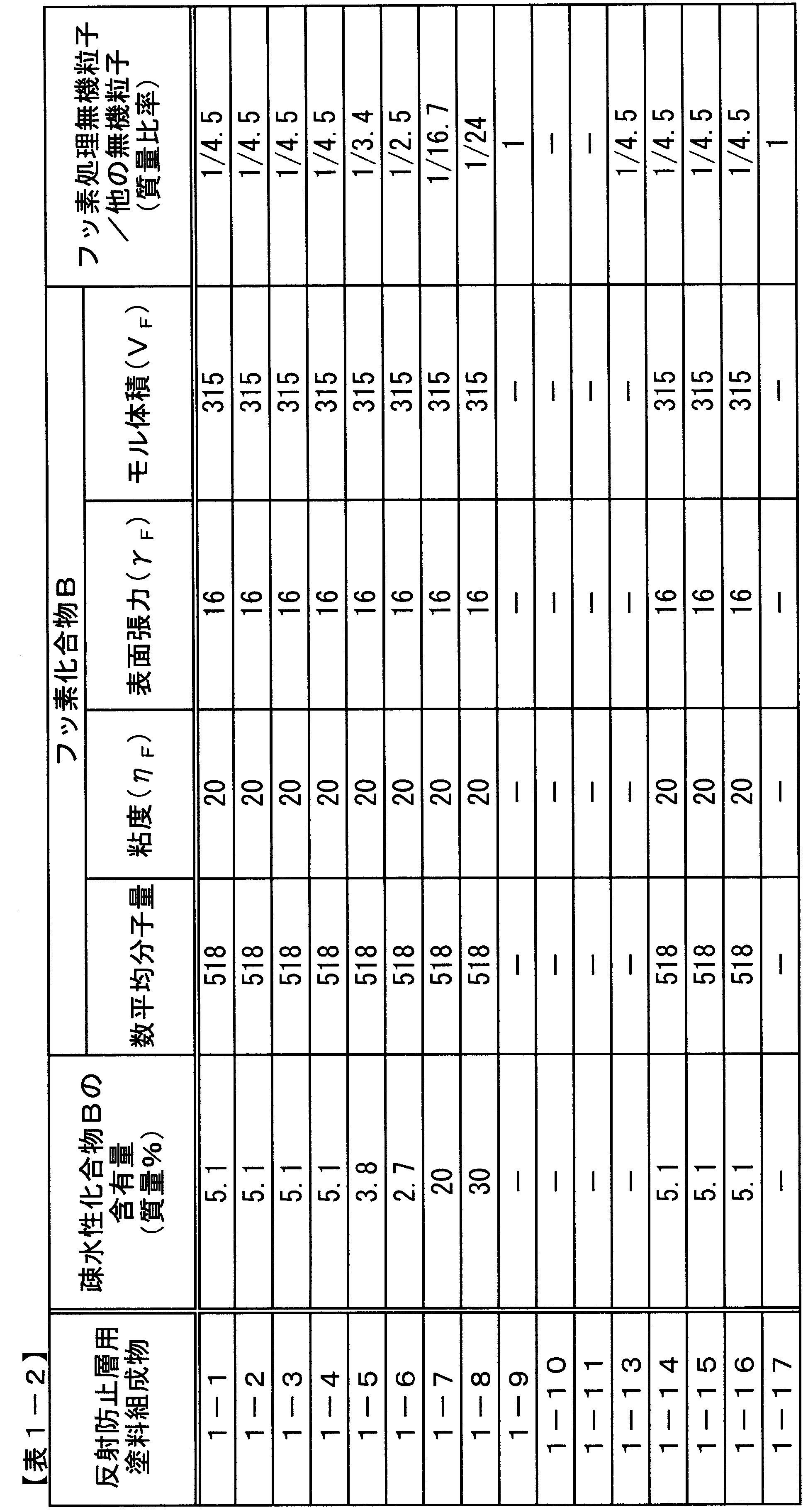
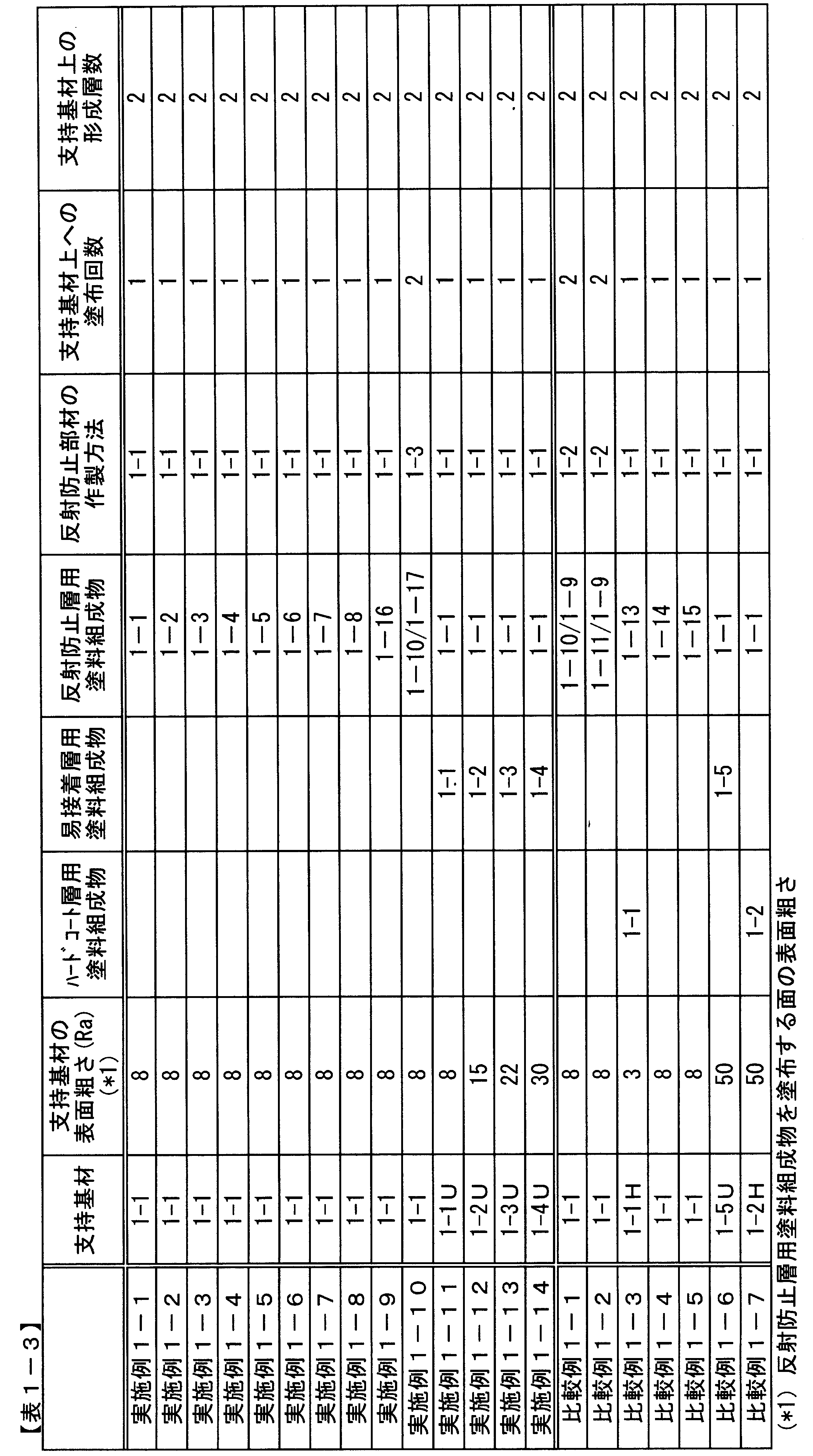


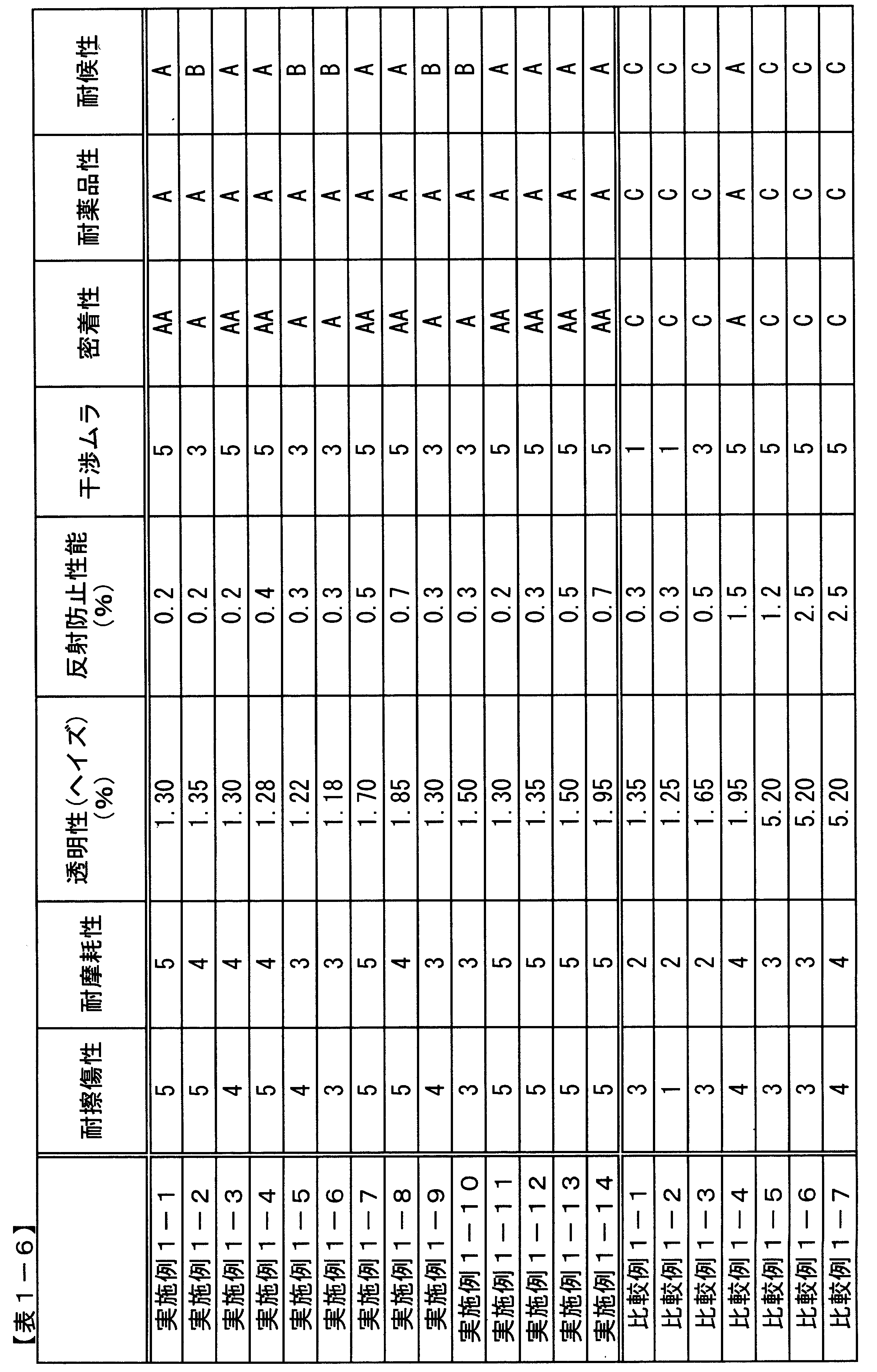
[高屈折率層成分(2-a)]
酸化チタン粒子を含有するELCOM TO1019TIC(日揮触媒化成(株)製:固形分30質量%)6質量部と多官能アクリレートであるカヤラッドDPHA(日本化薬(株)製:固形分100質量%)1質量部を混合し、固形分濃度40質量%の高屈率層成分(2-a)を得た。
アンチモン含有酸化スズ粒子を含有するオプスターTU4005(JSR社製:固形分30質量%)6質量部と多官能アクリレートであるカヤラッドDPHA(日本化薬株(株)製:固形分100質量%)1質量部を混合し、固形分濃度40質量%の高屈率層成分(2-b)を得た。
酸化ジルコニウム粒子を含有するTYZ67-H01(東洋インキ(株)製:固形分30質量%)6質量部と多官能アクリレートであるカヤラッドDPHA(日本化薬(株)製:固形分100質量%)1質量部を混合し、固形分40質量%の高屈折率層成分(2-c)を得た。
酸化チタン粒子を含有するELCOM TO1019TIC(日揮触媒化成(株)製:固形分30質量%)6質量部と多官能アクリレートであるカヤラッドDPHA(日本化薬(株)製:固形分100質量%)1質量部を混合し、固形分濃度60質量%の高屈率層成分(2-d)を得た。
酸化チタン粒子を含有するELCOM TO1019TIC(日揮触媒化成(株)製:固形分30質量%)6質量部と多官能アクリレートであるカヤラッドDPHA(日本化薬(株)製:固形分100質量%)1質量部を混合し、固形分濃度3.5質量%の高屈率層成分(2-e)を得た。
酸化アンチモン含有酸化スズであるオプスターTU4005(JSR社製:固形分30質量%)6質量部と多官能アクリレートであるカヤラッドDPHA(日本化薬(株)製:固形分100質量%)1質量部を混合し、固形分濃度40質量%の高屈率層成分(2-f)を得た。
中空シリカであるスルーリア4110(日揮触媒化成(株)製:固形分濃度20質量%)15gに、メタクリロキシプロピルトリメトキシシラン1.37gと10質量%蟻酸水溶液0.17gを混合し、70℃にて1時間撹拌した。ついでH2C=CH-COO-CH2-(CF2)8F 1.38gと2,2-アゾビスイソブチロニトリル0.057gを加えた後、60分間90℃にて加熱撹拌した。その後、イソプロピルアルコールを加え希釈し、固形分濃度14質量%の低屈折率層成分(2-a)とした。
中空シリカであるスルーリア4110(日揮触媒化成(株)製:固形分濃度20質量%)15gに、メタクリロキシプロピルトリメトキシシラン1.37gと10質量%蟻酸水溶液0.17gを混合し、70℃にて1時間撹拌した。その後、イソプロピルアルコールを加え希釈し、固形分濃度14質量%の低屈折率層成分(2-b)を得た。
中空シリカであるスルーリア4110(日揮触媒化成(株)製:固形分濃度20質量%)15gに、イソプロピルアルコールを加え希釈し、固形分濃度14質量%の低屈折率層成分(2-c)を得た。
中空シリカであるスルーリア4110(日揮触媒化成(株)製:固形分濃度20質量%)15gに、メタクリロキシプロピルトリメトキシシラン1.37gと10質量%蟻酸水溶液0.17gを混合し、70℃にて1時間撹拌した。ついで、H2C=CH-COO-CH2-(CF2)8F 1.38gおよび2,2-アゾビスイソブチロニトリル0.057gを加えた後、60分間90℃にて加熱撹拌した。その後、イソプロピルアルコールを加え希釈し、固形分濃度3.5質量%の低屈折率層成分(2-d)を得た。
低屈折率層成分(2-a)と高屈折率層成分(2-a)をそれぞれ質量比にて1:7となるように混合した溶液100質量部に、2-ヒドロキシ-2-メチル-1-フェニル-プロパン-1-オンを3質量部添加した。さらにフッ素化合物BであるH2C=CH-COO-CH2-(CF2)8Fを、含有量が30質量%となるように添加し、反射防止層用塗料組成物2-1を得た。
低屈折率層成分(2-a)と高屈折率層成分(2-c)をそれぞれ質量比にて1:7となるように混合した溶液100質量部に、2-ヒドロキシ-2-メチル-1-フェニル-プロパン-1-オンを3質量部添加した。さらにフッ素化合物BであるH2C=CH-COO-CH2-(CF2)8Fを、含有量が10質量%となるように添加し、反射防止層用塗料組成物2-2とした。
低屈折率層成分(2-a)と高屈折率層成分(2-b)をそれぞれ質量比にて1:7となるように混合した溶液100質量部に、2-ヒドロキシ-2-メチル-1-フェニル-プロパン-1-オンを3質量部添加した。さらにフッ素化合物BであるH2C=CH-COO-CH2-(CF2)8Fを、含有量が30質量%となるように添加し、反射防止層用塗料組成物2-3とした。
低屈折率層成分(2-a)と高屈折率層成分(2-a)をそれぞれ質量比にて1:7となるように混合した溶液100質量部に、2-ヒドロキシ-2-メチル-1-フェニル-プロパン-1-オンを3質量部添加した。さらにフッ素化合物BであるH2C=CH-COO-CH2-(CF2)8Fを、含有量が40質量%となるように添加し、反射防止層用塗料組成物2-4とした。
低屈折率層成分(2-a)と高屈折率層成分(2-a)をそれぞれ質量比にて1:7となるように混合した溶液100質量部に、2-ヒドロキシ-2-メチル-1-フェニル-プロパン-1-オンを3質量部添加した。さらにフッ素化合物BであるH2C=CH-COO-CH2-(CF2)6Fを、含有量が30質量%となるように添加し、反射防止層用塗料組成物2-5とした。
低屈折率層成分(2-a)と高屈折率層成分(2-a)をそれぞれ質量比にて1:7となるように混合し、2-ヒドロキシ-2-メチル-1-フェニル-プロパン-1-オンを3質量部添加した。さらにフッ素化合物BであるH2C=CH-COO-CH2-(CF2)6Fを、含有量が20質量%となるように添加し、反射防止層用塗料組成物2-6とした。
低屈折率層成分(2-a)と高屈折率層成分(2-a)をそれぞれ質量比にて1:7となるように混合した溶液100質量部に、2-ヒドロキシ-2-メチル-1-フェニル-プロパン-1-オンを3質量部添加した。さらにフッ素化合物BであるH2C=CH-COO-CH2-(CF2)4Fを、含有量が30質量%となるように添加し、反射防止層用塗料組成物2-7とした。
低屈折率層成分(2-a)と高屈折率層成分(2-a)をそれぞれ質量比にて1:7となるように混合した溶液100質量部に、2-ヒドロキシ-2-メチル-1-フェニル-プロパン-1-オンを3質量部添加した。さらにフッ素化合物BであるH2C=CH-COO-CH2-(CF2)4Fを、含有量が20質量%となるように添加し、反射防止層用塗料組成物2-8とした。
低屈折率層成分(2-a)と高屈折率層成分(2-a)をそれぞれ質量比にて1:7となるように混合した溶液100質量部に、2-ヒドロキシ-2-メチル-1-フェニル-プロパン-1-オンを3質量部添加した。さらにフッ素化合物であるH2C=CH-COO-CH2CF2CF3を、含有量が30質量%となるように添加し、反射防止層用塗料組成物2-9とした。
低屈折率層成分(2-a)と高屈折率層成分(2-a)をそれぞれ質量比にて1:7となるように混合した溶液100質量部に、2-ヒドロキシ-2-メチル-1-フェニル-プロパン-1-オンを3質量部添加した。さらにフッ素化合物BであるCF3(CF2)7CH2CH2Si(OCH3)3を、含有量が20質量%となるように添加し、反射防止層用塗料組成物2-10とした。
低屈折率層成分(2-a)と高屈折率層成分(2-a)をそれぞれ質量比にて1:7となるように混合した溶液100質量部に、2-ヒドロキシ-2-メチル-1-フェニル-プロパン-1-オンを3質量部添加した。さらにフッ素化合物BであるCF3(CF2)5CH2CH2Si(OCH3)3を、含有量が25質量%となるように添加し、反射防止層用塗料組成物2-11とした。
低屈折率層成分(2-a)と高屈折率層成分(2-a)をそれぞれ質量比にて1:7となるように混合した溶液100質量部に、2-ヒドロキシ-2-メチル-1-フェニル-プロパン-1-オンを3質量部添加した。さらにフッ素化合物BであるCF3(CF2)7CH2CH2Si(OH)3の9量体オリゴマーを、含有量が5質量%となるように添加し、反射防止層用塗料組成物2-12とした。
低屈折率層成分(2-a)と高屈折率層成分(2-a)をそれぞれ質量比にて1:7となるように混合した溶液100質量部に、2-ヒドロキシ-2-メチル-1-フェニル-プロパン-1-オンを3質量部添加した。さらにフッ素化合物BであるCF3(CF2)7CH2CH2Si(OH)3の7量体オリゴマーを、含有量が10質量%となるように添加し、反射防止層用塗料組成物2-13とした。
低屈折率層成分(2-a)と高屈折率層成分(2-a)をそれぞれ質量比にて1:7となるように混合した溶液100質量部に、2-ヒドロキシ-2-メチル-1-フェニル-プロパン-1-オンを3質量部添加した。さらにフッ素化合物BであるH2C=CH-COO-CH2-(CF2)8Fの6量体オリゴマーを、含有量が15質量%となるように添加し、反射防止層用塗料組成物2-14とした。
低屈折率層成分(2-a)と高屈折率層成分(2-a)をそれぞれ質量比にて1:7となるように混合した溶液100質量部に、2-ヒドロキシ-2-メチル-1-フェニル-プロパン-1-オンを3質量部添加した。さらにフッ素化合物BであるCF3(CF2)7CH2CH2Si(OH)3の3量体オリゴマーを、含有量が20質量%となるように添加し、反射防止層用塗料組成物2-15とした。
低屈折率層成分(2-a)と高屈折率層成分(2-a)をそれぞれ質量比にて1:7となるように混合した溶液100質量部に、2-ヒドロキシ-2-メチル-1-フェニル-プロパン-1-オンを3質量部添加した。さらにフッ素化合物であるHO-CH2-CF2CF3を、含有量が20質量%となるように添加し、反射防止層用塗料組成物2-16とした。
低屈折率層成分(2-a)と高屈折率層成分(2-a)をそれぞれ質量比にて1:7となるように混合した溶液100質量部に、2-ヒドロキシ-2-メチル-1-フェニル-プロパン-1-オンを3質量部添加した。さらにフッ素化合物であるHO-CH2-CF3を、含有量が20質量%となるように添加し、反射防止層用2-17塗料組成物とした。
低屈折率層成分(2-a)と高屈折率層成分(2-a)をそれぞれ質量比にて1:7となるように混合した溶液100質量部に、2-ヒドロキシ-2-メチル-1-フェニル-プロパン-1-オンを3質量部添加した。さらにフッ素化合物であるH2C=CH-COO-CH2-CF3を、含有量が20質量%となるように添加し、反射防止層用塗料組成物2-18とした。
低屈折率層成分(2-b)と高屈折率層成分(2-a)をそれぞれ質量比にて1:7となるように混合した溶液100質量部に、2-ヒドロキシ-2-メチル-1-フェニル-プロパン-1-オンを3質量部添加した。さらにフッ素化合物BであるH2C=CH-COO-CH2-(CF2)8Fを、含有量が30質量%となるように添加し、反射防止層用塗料組成物2-19とした。
低屈折率層成分(2-c)と高屈折率層成分(2-a)をそれぞれ質量比にて1:7となるように混合した溶液100質量部に、2-ヒドロキシ-2-メチル-1-フェニル-プロパン-1-オンを3質量部添加した。さらにフッ素化合物BであるH2C=CH-COO-CH2-(CF2)8Fを、含有量が30質量%となるように添加し、反射防止層用塗料組成物2-20とした。
低屈折率層成分(2-a)と高屈折率層成分(2-d)をそれぞれ質量比にて1:7となるように混合した溶液100質量部に、2-ヒドロキシ-2-メチル-1-フェニル-プロパン-1-オンを3質量部添加した。さらにフッ素化合物BであるH2C=CH-COO-CH2-(CF2)8Fを、含有量が30質量%となるように添加し、反射防止層用塗料組成物2-21とした。
低屈折率層成分(2-d)と高屈折率層成分(2-e)をそれぞれ質量比にて1:1となるように混合した溶液100質量部に、2-ヒドロキシ-2-メチル-1-フェニル-プロパン-1-オンを3質量部添加した。さらにフッ素化合物BであるH2C=CH-COO-CH2-(CF2)8Fを、含有量が1質量%となるように添加し、反射防止層用塗料組成物2-22とした。
低屈折率層成分(2-a)と高屈折率層成分(2-a)をそれぞれ質量比にて1:7となるように混合した溶液100質量部に、2-ヒドロキシ-2-メチル-1-フェニル-プロパン-1-オンを3質量部添加した。さらにアクリレートモノマーであるトリメチロールプロパンEO変性トリアクリレート[CH2=CHCO-(OCH2H4)n-OCH2]3-CCH2CH3を、含有量が44質量%となるように添加し、反射防止層用塗料組成物2-23とした。
フッ素化合物Bを含まない以外は反射防止層用塗料組成物2-1と同様に作成し、反射防止層用塗料組成物2-24とした。
低屈折率層成分(2-d)と高屈折率層成分(2-e)をそれぞれ質量比にて10:1となるように混合した溶液100質量部に、2-ヒドロキシ-2-メチル-1-フェニル-プロパン-1-オンを3質量部添加した。さらにフッ素化合物BであるH2C=CH-COO-CH2-(CF2)8Fを、含有量が1質量%となるように添加し、反射防止層用塗料組成物2-25とした。
低屈折率層成分(2-a)と高屈折率層成分(2-f)をそれぞれ質量比にて1:7となるように混合した溶液100質量部に、2-ヒドロキシ-2-メチル-1-フェニル-プロパン-1-オンを3質量部添加し、反射防止層用塗料組成物2-26とした。
低屈折率層成分(2-a)と高屈折率層成分(2-a)をそれぞれ質量比にて1:7となるように混合した溶液100質量部に、2-ヒドロキシ-2-メチル-1-フェニル-プロパン-1-オンを3質量部添加した。さらにシリコーン化合物BであるPC-4131(大日本インキ化学工業(株)製)を、含有量が20質量%となるように添加し、反射防止層用塗料組成物2-27とした。
低屈折率層成分(2-a)と高屈折率層成分(2-a)をそれぞれ質量比にて1:7となるように混合した溶液100質量部に、2-ヒドロキシ-2-メチル-1-フェニル-プロパン-1-オンを3質量部添加した。さらに長鎖炭化水素化合物Bであるn-デシルトリメトキシシラン(Z-6210、東レ・ダウコーニング(株)製)を、含有量が20質量%となるように添加し、反射防止層用塗料組成物2-28とした。
低屈折率層成分(2-a)と高屈折率層成分(2-a)をそれぞれ質量比にて1:7となるように混合した溶液100質量部に、2-ヒドロキシ-2-メチル-1-フェニル-プロパン-1-オンを3質量部添加した。さらにフッ素化合物BであるH2C=CH-COO-CH2-(CF2)8Fとシリコーン化合物AであるPC-4131を、含有量がそれぞれ2.5質量%と2.5質量%となるように添加し、反射防止層用塗料組成物2-29とした。
低屈折率層成分(2-a)と高屈折率層成分(2-a)をそれぞれ質量比にて1:7となるように混合した溶液100質量部に、2-ヒドロキシ-2-メチル-1-フェニル-プロパン-1-オンを3質量部添加した。さらにフッ素化合物BであるH2C=CH-COO-CH2-(CF2)8Fと長鎖炭化水素化合物Bであるn-オクチルトリトリエトキシシラン(Z-6341、東レ・ダウコーニング(株)製)を、含有量がそれぞれ2.5質量%と2.5質量%となるように添加し、反射防止層用塗料組成物2-30とした。
低屈折率層成分(2-a)と高屈折率層成分(2-a)をそれぞれ質量比にて1:7となるように混合した溶液100質量部に、2-ヒドロキシ-2-メチル-1-フェニル-プロパン-1-オンを3質量部添加し、反射防止層用塗料組成物2-31とした。
低屈折率層成分(2-a)と高屈折率層成分(2-a)をそれぞれ質量比にて1:7となるように混合した溶液100質量部に、2-ヒドロキシ-2-メチル-1-フェニル-プロパン-1-オンを3質量部添加し、反射防止層用塗料組成物2-32とした。
低屈折率層成分(2-b)と高屈折率層成分(2-a)をそれぞれ質量比にて1:7となるように混合した溶液100質量部に、2-ヒドロキシ-2-メチル-1-フェニル-プロパン-1-オンを3質量部添加し、反射防止層用塗料組成物2-33とした。
支持基材としてPETフィルム上に易接着性層が形成されているU46(東レフィルム加工(株)製)を用いた。この支持基材の易接着層面上に、表2-5,2-6に記載の反射防止層用塗料組成物を、バーコーター(#10)を用いて塗工した。塗工後、100℃にて2分間乾燥し、160W/cmの高圧水銀灯ランプ(アイグラフィックス(株)製)を用いて、照度600W/cm2、積算光量800mJ/cm2の紫外線を、酸素濃度0.1体積%の下で照射し、反射防止部材を作製した。
前記製造例1と同じ方法により、評価を行った。
粘度変化(Δη)が10mPa・sを越える反射防止層用塗料組成物を使用した参考比較例2-2,2-3,2-6~2-9の反射防止部材は、反射防止性、透明性に劣り、第1層と第2層の明確な界面が見られなかった。
フッ素処理無機粒子を含有しない反射防止層用塗料組成物を使用した参考比較例2-4,2-5,2-9の反射防止部材は、反射防止性、透明性に劣り、第1層と第2層の明確な界面が見られなかった。

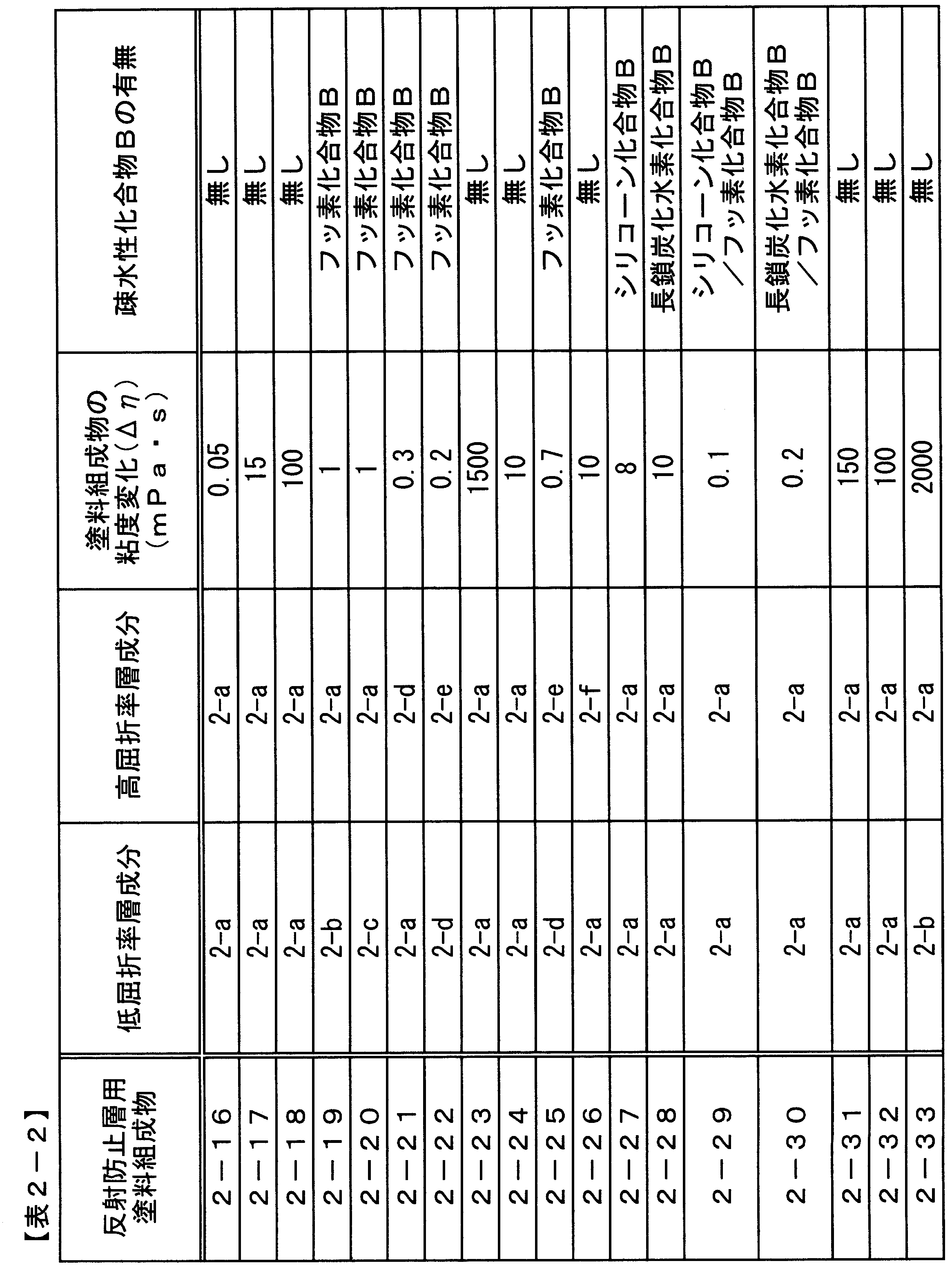


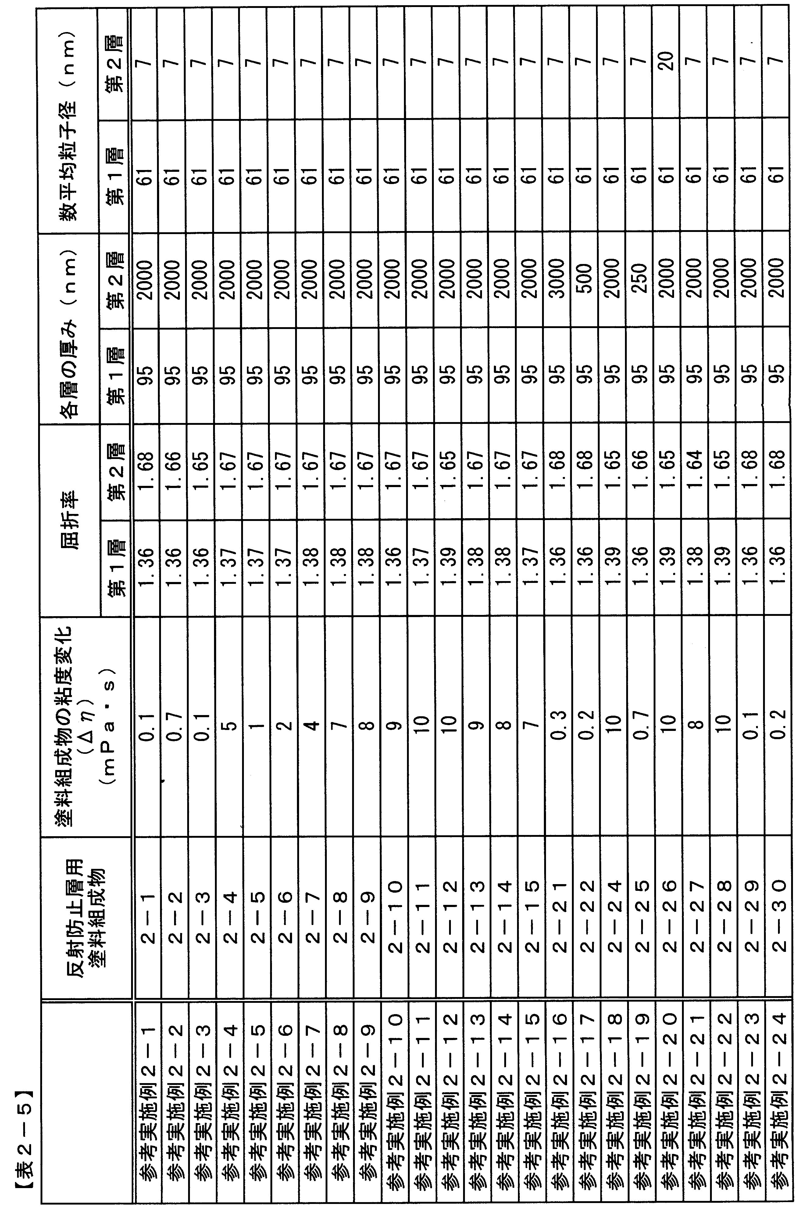

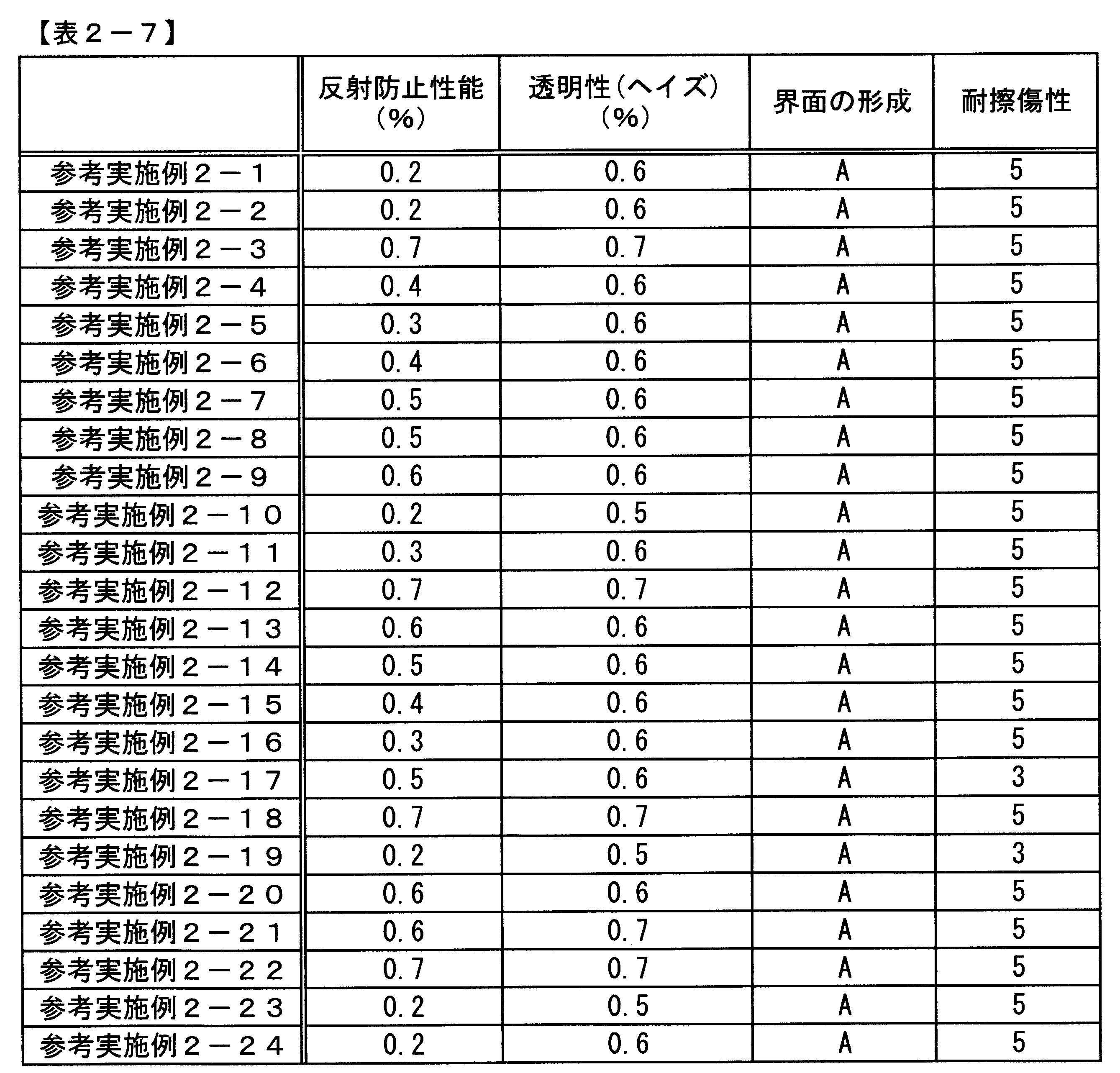

[高屈折率層成分(3-a)]
酸化チタン粒子を含有するELCOM TO1019TIC(日揮触媒化成(株)製:固形分30質量%)6質量部と多官能アクリレートであるカヤラッドDPHA(日本化薬(株)製:固形分100質量%)1質量部を混合し、固形分濃度40質量%の高屈折率層成分(3-a)を得た。
アンチモン含有酸化スズ粒子を含有するオプスターTU4005(JSR社製:固形分30質量%)6質量部と多官能アクリレートであるカヤラッドDPHA(日本化薬(株)製:固形分100質量%)1質量部を混合し、固形分濃度40質量%の高屈折率層成分(3-b)を得た。
酸化ジルコニウム粒子を含有するTYZ67-H01(東洋インキ(株)製:固形分30質量%)6質量部と多官能アクリレートであるカヤラッドDPHA(日本化薬(株)製:固形分100質量%)1質量部を混合し、固形分40質量%の高屈折率層成分(3-c)を得た。
酸化チタン粒子を含有するELCOM TO1019TIC(日揮触媒化成(株)製:固形分30質量%)6質量部と多官能アクリレートであるカヤラッドDPHA(日本化薬(株)製:固形分100質量%)1質量部を混合し、固形分濃度60質量%の高屈折率層成分(3-d)を得た。
酸化チタン粒子を含有するELCOM TO1019TIC(日揮触媒化成(株)製:固形分30質量%)6質量部と多官能アクリレートであるカヤラッドDPHA(日本化薬(株)製:固形分100質量%)1質量部を混合し、固形分濃度3.5質量%の高屈折率層成分(3-e)を得た。
酸化チタン粒子を含有するELCOM TO1019TIC(日揮触媒化成(株)製:固形分30質量%)6質量部と多官能アクリレートであるカヤラッドDPHA(日本化薬(株)製:固形分100質量%)1質量部を混合し、固形分濃度35質量%の高屈折率層成分(3-f)を得た。
中空シリカであるスルーリア4110(日揮触媒化成(株)製:固形分濃度20質量%)15gに、メタクリロキシプロピルトリメトキシシラン1.37gと10質量%蟻酸水溶液0.17gを混合し、70℃にて1時間撹拌した。ついで、H2C=CH-COO-CH2-(CF2)8F 1.38gおよび2,2-アゾビスイソブチロニトリル0.057gを加えた後、60分間90℃にて加熱撹拌した。その後、イソプロピルアルコールを加え希釈し、固形分濃度14質量%の低屈折率層成分(3-a)を得た。
中空シリカであるスルーリア4110(日揮触媒化成(株)製:固形分濃度20質量%)15gに、メタクリロキシプロピルトリメトキシシラン1.37gと10質量%蟻酸水溶液0.17gを混合し、70℃にて1時間撹拌した。その後、イソプロピルアルコールを加え希釈し、固形分濃度14質量%の低屈折率層成分(3-b)を得た。
中空シリカであるスルーリア4110(日揮触媒化成(株)製:固形分濃度20質量%)15gに、イソプロピルアルコールを加え希釈し、固形分濃度14質量%の低屈折率層成分(3-c)を得た。
中空シリカであるスルーリア4110(日揮触媒化成(株)製:固形分濃度20質量%)15gに、メタクリロキシプロピルトリメトキシシラン1.37gと10質量%蟻酸水溶液0.17gを混合し、70℃にて1時間撹拌した。ついで、H2C=CH-COO-CH2-(CF2)8F 1.38gおよび2,2-アゾビスイソブチロニトリル0.057gを加えた後、60分間90℃にて加熱撹拌した。その後、イソプロピルアルコールを加え希釈し、固形分濃度3.5質量%の低屈折率層成分(3-d)を得た。
低屈折率層成分(3-a)と高屈折率層成分(3-a)をそれぞれ質量比にて1:7となるように混合した溶液100質量部に、2-ヒドロキシ-2-メチル-1-フェニル-プロパン-1-オンを3質量部添加した。さらにフッ素化合物BであるH2C=CH-COO-CH2-(CF2)8Fを、塗料組成物全体に対する含有量が30質量%となるように添加し、反射防止層用塗料組成物3-1とした。
低屈折率層成分(3-a)と高屈折率層成分(3-c)をそれぞれ質量比にて1:7となるように混合した溶液100質量部に、2-ヒドロキシ-2-メチル-1-フェニル-プロパン-1-オンを3質量部添加した。さらにフッ素化合物BであるH2C=CH-COO-CH2-(CF2)8Fを、塗料組成物全体に対する含有量が10質量%となるように添加し、反射防止層用塗料組成物3-2とした。
低屈折率層成分(3-a)と高屈折率層成分(3-b)をそれぞれ質量比にて1:7となるように混合した溶液100質量部に、2-ヒドロキシ-2-メチル-1-フェニル-プロパン-1-オンを3質量部添加した。さらにフッ素化合物BであるH2C=CH-COO-CH2-(CF2)8Fを、塗料組成物全体に対する含有量が30質量%となるように添加し、反射防止層用塗料組成物3-3とした。
低屈折率層成分(3-a)と高屈折率層成分(3-a)をそれぞれ質量比にて1:7となるように混合した溶液100質量部に、2-ヒドロキシ-2-メチル-1-フェニル-プロパン-1-オンを3質量部添加した。さらにフッ素化合物BであるH2C=CH-COO-CH2-(CF2)8Fを、塗料組成物全体に対する含有量が40質量%となるように添加し、反射防止層用塗料組成物3-4とした。
低屈折率層成分(3-a)と高屈折率層成分(3-a)をそれぞれ質量比にて1:7となるように混合した溶液100質量部に、2-ヒドロキシ-2-メチル-1-フェニル-プロパン-1-オンを3質量部添加した。さらにフッ素化合物BであるH2C=CH-COO-CH2-(CF2)6Fを、塗料組成物全体に対する含有量が50質量%となるように添加し、反射防止層用塗料組成物3-5とした。
低屈折率層成分(3-a)と高屈折率層成分(3-a)をそれぞれ質量比にて1:7となるように混合し、2-ヒドロキシ-2-メチル-1-フェニル-プロパン-1-オンを3質量部添加した。さらにフッ素化合物BであるH2C=CH-COO-CH2-(CF2)6Fを、塗料組成物全体に対する含有量が20質量%となるように添加し、反射防止層用塗料組成物3-6とした。
低屈折率層成分(3-a)と高屈折率層成分(3-a)をそれぞれ質量比にて1:7となるように混合した溶液100質量部に、2-ヒドロキシ-2-メチル-1-フェニル-プロパン-1-オンを3質量部添加した。さらにフッ素化合物BであるH2C=CH-COO-CH2-(CF2)4Fを、塗料組成物全体に対する含有量が30質量%となるように添加し、反射防止層用塗料組成物3-7とした。
低屈折率層成分(3-a)と高屈折率層成分(3-a)をそれぞれ質量比にて1:7となるように混合した溶液100質量部に、2-ヒドロキシ-2-メチル-1-フェニル-プロパン-1-オンを3質量部添加した。さらにフッ素化合物BであるH2C=CH-COO-CH2-(CF2)4Fを、塗料組成物全体に対する含有量が20質量%となるように添加し、反射防止層用塗料組成物3-8とした。
低屈折率層成分(3-a)と高屈折率層成分(3-a)をそれぞれ質量比にて1:7となるように混合した溶液100質量部に、2-ヒドロキシ-2-メチル-1-フェニル-プロパン-1-オンを3質量部添加した。さらにフッ素化合物であるH2C=CH-COO-CH2CF2CF3を、塗料組成物全体に対する含有量が40質量%となるように添加し、反射防止層用塗料組成物とした。
低屈折率層成分(3-a)と高屈折率層成分(3-a)をそれぞれ質量比にて1:7となるように混合した溶液100質量部に、2-ヒドロキシ-2-メチル-1-フェニル-プロパン-1-オンを3質量部添加した。さらにフッ素化合物BであるCF3(CF2)7CH2CH2Si(OCH3)3を、塗料組成物全体に対する含有量が20質量%となるように添加し、反射防止層用塗料組成物3-10とした。
低屈折率層成分(3-a)と高屈折率層成分(3-a)をそれぞれ質量比にて1:7となるように混合した溶液100質量部に、2-ヒドロキシ-2-メチル-1-フェニル-プロパン-1-オンを3質量部添加した。さらにフッ素化合物BであるCF3(CF2)5CH2CH2Si(OCH3)3を、塗料組成物全体に対する含有量が25質量%となるように添加し、反射防止層用塗料組成物3-11とした。
低屈折率層成分(3-a)と高屈折率層成分(3-a)をそれぞれ質量比にて1:7となるように混合した溶液100質量部に、2-ヒドロキシ-2-メチル-1-フェニル-プロパン-1-オンを3質量部添加した。さらにフッ素化合物であるCF3(CF2)7CH2CH2Si(OH)3の9量体オリゴマーを、塗料組成物全体に対する含有量が20質量%となるように添加し、反射防止層用塗料組成物3-12とした。
低屈折率層成分(3-a)と高屈折率層成分(3-a)をそれぞれ質量比にて1:7となるように混合した溶液100質量部に、2-ヒドロキシ-2-メチル-1-フェニル-プロパン-1-オンを3質量部添加した。さらにフッ素化合物BであるCF3(CF2)7CH2CH2Si(OH)3の7量体オリゴマーを、塗料組成物全体に対する含有量が10質量%となるように添加し、反射防止層用塗料組成物3-13とした。
低屈折率層成分(3-a)と高屈折率層成分(3-a)をそれぞれ質量比にて1:7となるように混合した溶液100質量部に、2-ヒドロキシ-2-メチル-1-フェニル-プロパン-1-オンを3質量部添加した。さらにフッ素化合物BであるCF3(CF2)7CH2CH2Si(OH)3の5量体オリゴマーを、塗料組成物全体に対する含有量が15質量%となるように添加し、反射防止層用塗料組成物3-14とした。
低屈折率層成分(3-a)と高屈折率層成分(3-a)をそれぞれ質量比にて1:7となるように混合した溶液100質量部に、2-ヒドロキシ-2-メチル-1-フェニル-プロパン-1-オンを3質量部添加した。さらにフッ素化合物BであるCF3(CF2)7CH2CH2Si(OH)3の3量体オリゴマーを、塗料組成物全体に対する含有量が20質量%となるように添加し、反射防止層用塗料組成物3-15とした。
低屈折率層成分(3-a)と高屈折率層成分(3-a)をそれぞれ質量比にて1:7となるように混合した溶液100質量部に、2-ヒドロキシ-2-メチル-1-フェニル-プロパン-1-オンを3質量部添加した。さらにフッ素化合物であるHO-CH2-CF2CF3を、塗料組成物全体に対する含有量が20質量%となるように添加し、反射防止層用塗料組成物3-16とした。
低屈折率層成分(3-a)と高屈折率層成分(3-a)をそれぞれ質量比にて1:7となるように混合した溶液100質量部に、2-ヒドロキシ-2-メチル-1-フェニル-プロパン-1-オンを3質量部添加した。さらにフッ素化合物であるHO-CH2-CF3を、塗料組成物全体に対する含有量が20質量%となるように添加し、反射防止層用塗料組成物3-17とした。
低屈折率層成分(3-a)と高屈折率層成分(3-a)をそれぞれ質量比にて1:7となるように混合した溶液100質量部に、2-ヒドロキシ-2-メチル-1-フェニル-プロパン-1-オンを3質量部添加し、さらにフッ素化合物であるH2C=CH-COO-CH2-CF3を、塗料組成物全体に対する含有量が20質量%となるように添加し、反射防止層用塗料組成物3-18とした。
低屈折率層成分(3-b)と高屈折率層成分(3-a)をそれぞれ質量比にて1:7となるように混合した溶液100質量部に、2-ヒドロキシ-2-メチル-1-フェニル-プロパン-1-オンを3質量部添加した。さらにフッ素化合物BであるH2C=CH-COO-CH2-(CF2)8Fを、塗料組成物全体に対する含有量が30質量%となるように添加し、反射防止層用塗料組成物3-19とした。
低屈折率層成分(3-c)と高屈折率層成分(3-a)をそれぞれ質量比にて1:7となるように混合した溶液100質量部に、2-ヒドロキシ-2-メチル-1-フェニル-プロパン-1-オンを3質量部添加した。さらにフッ素化合物BであるH2C=CH-COO-CH2-(CF2)8Fを、塗料組成物全体に対する含有量が30質量%となるように添加し、反射防止層用塗料組成物3-20とした。
低屈折率層成分(3-a)と高屈折率層成分(3-d)をそれぞれ質量比にて1:7となるように混合した溶液100質量部に、2-ヒドロキシ-2-メチル-1-フェニル-プロパン-1-オンを3質量部添加した。さらにフッ素化合物BであるH2C=CH-COO-CH2-(CF2)8Fを、塗料組成物全体に対する含有量が30質量%となるように添加し、反射防止層用塗料組成物3-21とした。
低屈折率層成分(3-d)と高屈折率層成分(3-e)をそれぞれ質量比にて1:1となるように混合した溶液100質量部に、2-ヒドロキシ-2-メチル-1-フェニル-プロパン-1-オンを3質量部添加した。さらにフッ素化合物BであるH2C=CH-COO-CH2-(CF2)8Fを、塗料組成物全体に対する含有量が5質量%となるように添加し、反射防止層用塗料組成物3-22とした。
フッ素化合物BであるH2C=CH-COO-CH2-(CF2)8Fの代わりに、アクリレートモノマーであるトリメチロールプロパンEO変性トリアクリレート[CH2=CHCO-(OCH2H4)n-OCH2]3-CCH2CH3を、塗料組成物全体に対する含有量が30質量%になるように添加した以外は、塗料組成物3-1と同じ組成で作成し、反射防止層用塗料組成物とした。
フッ素化合物を含まない以外は反射防止層用塗料組成物3-1と同様に作成し、反射防止層用塗料組成物3-24とした。
低屈折率層成分(3-d)と高屈折率層成分(3-e)をそれぞれ質量比にて10:1となるように混合した溶液100質量部に、2-ヒドロキシ-2-メチル-1-フェニル-プロパン-1-オンを3質量部添加した。さらにフッ素化合物BであるH2C=CH-COO-CH2-(CF2)8Fを、塗料組成物全体に対する含有量が5質量%となるように添加し、反射防止層用塗料組成物3-25とした。
低屈折率層成分(3-a)と高屈折率層成分(3-f)をそれぞれ質量比にて1:7となるように混合した溶液100質量部に、2-ヒドロキシ-2-メチル-1-フェニル-プロパン-1-オンを3質量部添加し、反射防止層用塗料組成物3-26とした。
高屈折率層成分(3-a)100質量部に、2-ヒドロキシ-2-メチル-1-フェニル-プロパン-1-オンを3質量部添加した。さらにフッ素化合物BであるH2C=CH-COO-CH2-(CF2)8Fを、高屈折率層成体に対する含有量が33質量%となるように添加し、高屈折率層成分(3-a-2)とした。また、低屈折率層成分として、低屈折率層成分(3-a)を用いた。
この高屈折率層成分(3-a-2)と低屈折率成分(3-a)の組合せを便宜的に反射防止用塗料組成物3-27とよぶ。
支持基材としてPET樹脂フィルム上に易接着性塗料が塗工されているU46(東レフィルム加工(株)製)を用いた。この支持基材の易接着塗料が塗工されている面上に、表3-2に記載の反射防止層用塗料組成物を、バーコーター(#10)を用いて塗工した。塗工後、100℃にて2分間乾燥し、160W/cmの高圧水銀灯ランプ(アイグラフィックス(株)製)を用いて、照度600W/cm2、積算光量800mJ/cm2の紫外線を、酸素濃度0.1体積%の下で照射し、反射防止部材を作製した。この反射防止部材の作製方法を作製方法3-1とした。
支持基材としてPET樹脂フィルム上に易接着塗料が塗工されているU46(東レフィルム加工(株)製)を用いた。この支持基材の易接着塗料が塗工されている面上に、高屈折率塗料(3-a-2)をバーコーター(#4)を用いて塗工した。塗工後、100℃にて1分間乾燥し、160W/cmの高圧水銀灯ランプ(アイグラフィックス(株)製)を用いて、照度600W/cm2、積算光量800mJ/cm2の紫外線を、酸素濃度0.1体積%の下で照射した。硬化した高屈折率塗料(3-a-2)の表面に低屈折率塗料(3-a)を、バーコーター(#6)を用いて塗工した。塗工後、100℃にて1分間乾燥し、160W/cmの高圧水銀灯ランプ(アイグラフィックス(株)製)を用いて、照度600W/cm2、積算光量800mJ/cm2の紫外線を、酸素濃度0.1体積%の下で照射し、反射防止部材を作製した。この反射防止部材の作製方法を作製方法3-2とした。
イオン強度比FL/FHが150より大きい参考比較例3-7,3-8の反射防止部材は、反射防止性、透明性、密着性、耐候性、耐薬品性に劣り、2層の明確な界面が見られなかった。
水性化合物Bに由来する成分を含まない反射防止層用塗料組成物を使用した参考比較例3-6~3-8の反射防止部材は、反射防止性、透明性、密着性、耐候性、耐薬品性に劣り、2層の明確な界面が見られなかった。
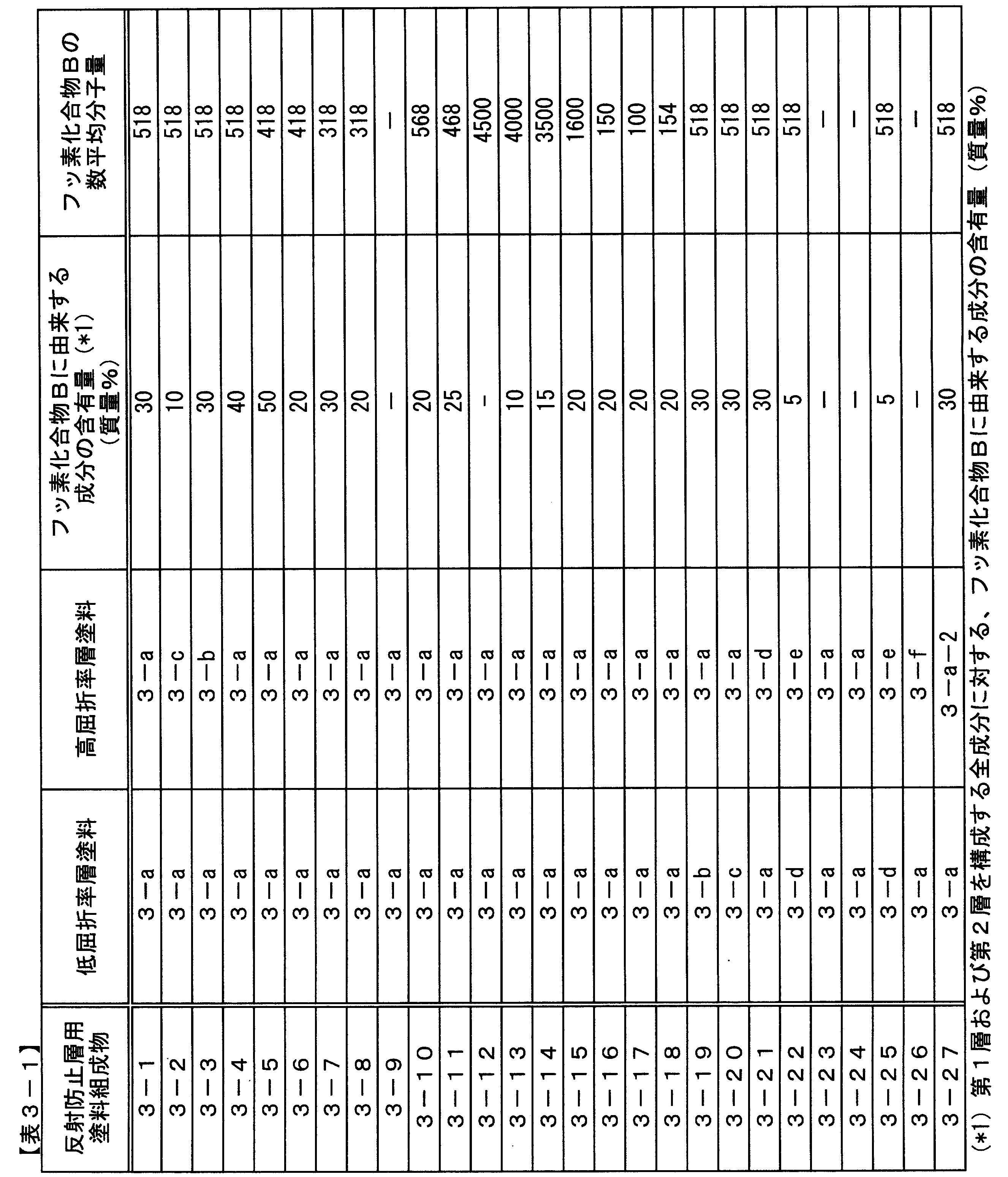
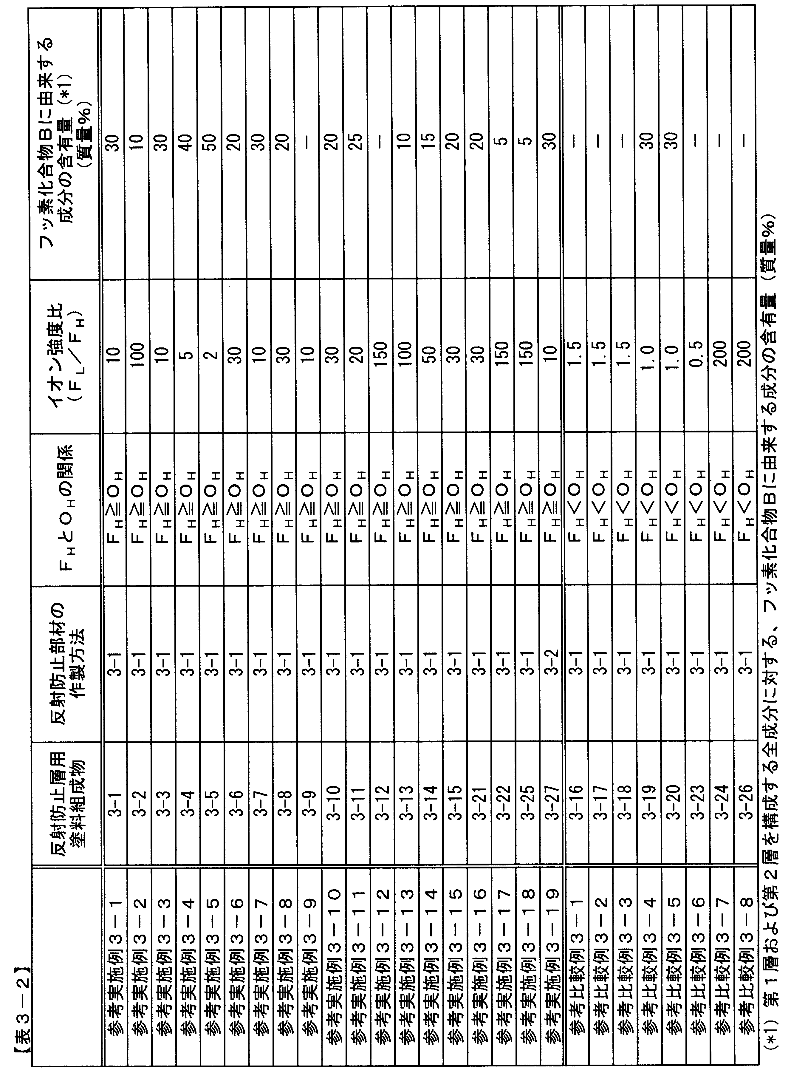

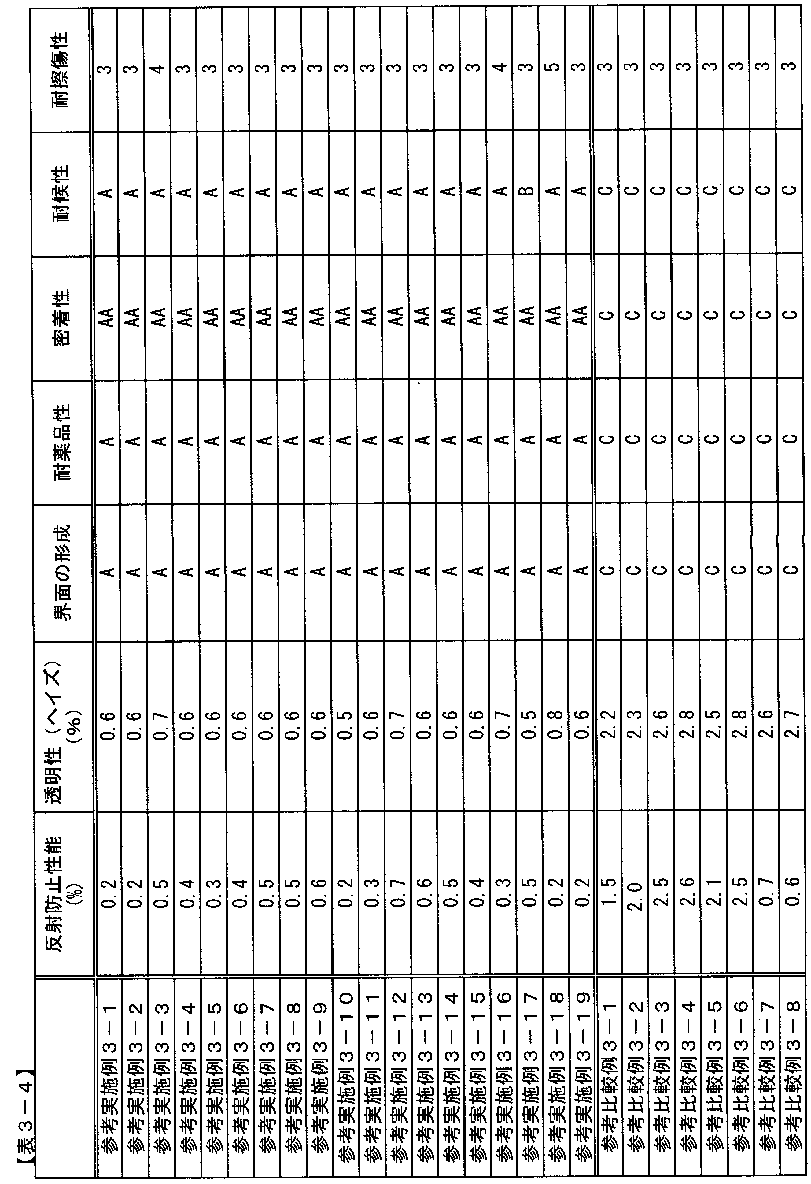
2 支持基材
3 反射防止層
4 低屈折率層
5 高屈折率ハードコート層
6 第2層に存在する粒子
7 第1層に存在する粒子
8 支持基材の第1の面
Claims (10)
- 支持基材の少なくとも第1の面に、屈折率の異なる2つの隣接する層を含む反射防止層を有し、これら屈折率の異なる2つの隣接する層が、前記支持基材から遠い側より第1層および第2層であり、
前記反射防止層が、構成元素が異なる2種類以上の粒子と1種類以上のバインダーとを含み、
前記第1層と第2層との界面上の直線距離が500nm以上の任意の2点をA1、A2としたとき、このA1とA2とを結ぶ線分A1A2の長さaと、この線分A1A2を、前記支持基材の第1の面に垂直な方向に、前記第1層と第2層との界面上へ投影した線の長さbとの比b/aが、1.10より大きく1.45未満である反射防止部材。 - 前記第2層の厚みが500nm以上4000nm以下である、請求項1の反射防止部材。
- 前記第2層中に存在する粒子の数平均粒子径が25nm以下である、請求項1または2の反射防止部材。
- 前記長さbと、前記線分A1A2を、前記支持基材の第1の面に垂直な方向に、前記反射防止層の前記支持基材側とは反対側の面へ投影した線の長さcとの比b/cが、1.05より大きく1.40未満である、請求項1から3のいずれかの反射防止部材。
- 前記第1層および第2層が、炭素数4以上のフルオロアルキル基および反応性部位を有する化合物、炭素数8以上の炭化水素基および反応性部位を有する化合物、ならびにシロキサン基および反応性部位を有する化合物からなる群より選ばれる少なくとも1つの化合物に由来する成分を含む、請求項1から4のいずれかの反射防止部材。
- 前記炭素数4以上のフルオロアルキル基および反応性部位を有する化合物の数平均分子量が、300以上4000以下である、請求項5の反射防止部材。
- 前記第1層の厚み方向の中心位置におけるSIMSによるフッ素原子のイオン強度FLと、前記第2層の厚み方向の中心位置におけるSIMSによるフッ素原子のイオン強度FHとの比FL/FHが、2以上150以下である、請求項1から6のいずれかの反射防止部材。
- 前記第2層の厚み方向の中心位置におけるSIMSによる酸素原子のイオン強度OHと、前記FHとの関係が、FH≧OHである、請求項7の反射防止部材。
- 請求項1から8のいずれかの反射防止部材を製造する方法であって、前記支持基材の少なくとも第1の面上に、塗料組成物を1回のみ塗工することで、屈折率の異なる2つの隣接する層を含む反射防止層を形成する反射防止部材の製造方法。
- 前記支持基材の第1の面のJIS-B-0601(2001年版)で規定される表面粗さが40nm以下である、請求項9の反射防止部材の製造方法。
Priority Applications (4)
| Application Number | Priority Date | Filing Date | Title |
|---|---|---|---|
| CN201080040352.XA CN102483469B (zh) | 2009-09-18 | 2010-09-08 | 防反射部件、和防反射部件的制造方法 |
| US13/394,359 US9423531B2 (en) | 2009-09-18 | 2010-09-08 | Antireflection member and manufacture method for the same |
| KR1020127001459A KR101773874B1 (ko) | 2009-09-18 | 2010-09-08 | 반사 방지 부재 및 그 제조 방법 |
| JP2010537062A JP6061444B2 (ja) | 2009-09-18 | 2010-09-08 | 反射防止部材、およびその製造方法 |
Applications Claiming Priority (6)
| Application Number | Priority Date | Filing Date | Title |
|---|---|---|---|
| JP2009-217096 | 2009-09-18 | ||
| JP2009217098 | 2009-09-18 | ||
| JP2009-217097 | 2009-09-18 | ||
| JP2009-217098 | 2009-09-18 | ||
| JP2009217096 | 2009-09-18 | ||
| JP2009217097 | 2009-09-18 |
Publications (1)
| Publication Number | Publication Date |
|---|---|
| WO2011033976A1 true WO2011033976A1 (ja) | 2011-03-24 |
Family
ID=43758584
Family Applications (1)
| Application Number | Title | Priority Date | Filing Date |
|---|---|---|---|
| PCT/JP2010/065411 Ceased WO2011033976A1 (ja) | 2009-09-18 | 2010-09-08 | 反射防止部材、およびその製造方法 |
Country Status (6)
| Country | Link |
|---|---|
| US (1) | US9423531B2 (ja) |
| JP (1) | JP6061444B2 (ja) |
| KR (1) | KR101773874B1 (ja) |
| CN (1) | CN102483469B (ja) |
| TW (1) | TWI502213B (ja) |
| WO (1) | WO2011033976A1 (ja) |
Cited By (17)
| Publication number | Priority date | Publication date | Assignee | Title |
|---|---|---|---|---|
| US20130222915A1 (en) * | 2011-08-26 | 2013-08-29 | Lg Chem, Ltd. | Anti-reflective coating film |
| JP2014052497A (ja) * | 2012-09-06 | 2014-03-20 | Dainippon Printing Co Ltd | 光学フィルム、光学フィルム用転写体、画像表示装置及び光学フィルムの製造方法 |
| CN103687720A (zh) * | 2011-08-11 | 2014-03-26 | 东丽株式会社 | 层叠体、透明导电性层叠体、接触面板、和层叠体的制造方法 |
| CN104334342A (zh) * | 2012-06-06 | 2015-02-04 | 东丽株式会社 | 叠层体、导电性叠层体和触摸面板、以及涂料组合物和使用该涂料组合物的叠层体的制造方法 |
| WO2018096921A1 (ja) * | 2016-11-25 | 2018-05-31 | リケンテクノス株式会社 | ハードコート積層フィルム |
| CN110632686A (zh) * | 2016-07-14 | 2019-12-31 | 株式会社Lg化学 | 防反射膜 |
| US10596739B2 (en) | 2015-03-18 | 2020-03-24 | Riken Technos Corporation | Molded body |
| US10780685B2 (en) | 2015-03-18 | 2020-09-22 | Riken Technos Corporation | Hard coat laminated film |
| US10809418B2 (en) | 2015-03-18 | 2020-10-20 | Riken Technos Corporation | Anti-glare hard coat laminated film |
| US10816700B2 (en) | 2015-12-08 | 2020-10-27 | Riken Technos Corporation | Hard coat layered film |
| US11065852B2 (en) | 2015-03-18 | 2021-07-20 | Riken Technos Corporation | Adhesive film |
| US11065851B2 (en) | 2015-03-18 | 2021-07-20 | Riken Technos Corporation | Multilayer hard coating film |
| US11241866B2 (en) | 2015-11-25 | 2022-02-08 | Riken Technos Corporation | Door body |
| US11352473B2 (en) | 2015-03-18 | 2022-06-07 | Riken Technos Corporation | Hard coat laminated film and method for producing same |
| US11407870B2 (en) | 2016-09-14 | 2022-08-09 | Riken Technos Corporation | Hard coat laminated film |
| US11433651B2 (en) | 2015-03-18 | 2022-09-06 | Riken Technos Corporation | Hard coat laminated film |
| US11774166B2 (en) | 2015-11-25 | 2023-10-03 | Riken Technos Corporation | Door body |
Families Citing this family (18)
| Publication number | Priority date | Publication date | Assignee | Title |
|---|---|---|---|---|
| US9274612B2 (en) | 2008-01-04 | 2016-03-01 | Tactus Technology, Inc. | User interface system |
| US9760172B2 (en) | 2008-01-04 | 2017-09-12 | Tactus Technology, Inc. | Dynamic tactile interface |
| US9612659B2 (en) | 2008-01-04 | 2017-04-04 | Tactus Technology, Inc. | User interface system |
| US9720501B2 (en) | 2008-01-04 | 2017-08-01 | Tactus Technology, Inc. | Dynamic tactile interface |
| US9552065B2 (en) * | 2008-01-04 | 2017-01-24 | Tactus Technology, Inc. | Dynamic tactile interface |
| WO2012054781A1 (en) | 2010-10-20 | 2012-04-26 | Tactus Technology | User interface system and method |
| JP2012214311A (ja) * | 2011-03-31 | 2012-11-08 | Canon Inc | 二酸化チタン分散液、二酸化チタン分散液の製造方法、および有機光学素子 |
| EP2927718B1 (en) | 2012-12-03 | 2018-09-19 | FUJIFILM Corporation | Ir-cut filter and manufacturing method thereof, solid state image pickup device, and light blocking film formation method |
| JP6274924B2 (ja) * | 2014-03-14 | 2018-02-07 | キヤノン株式会社 | 反射防止膜、光学部材及び光学部材の製造方法 |
| TWI673513B (zh) * | 2014-09-26 | 2019-10-01 | 日商大日本印刷股份有限公司 | 抗反射膜、顯示裝置及顯示裝置之抗反射膜之選擇方法 |
| KR101991928B1 (ko) | 2017-04-28 | 2019-06-21 | 주식회사 엘지화학 | 반사 방지 필름 |
| KR102361621B1 (ko) * | 2017-04-28 | 2022-02-09 | 주식회사 엘지화학 | 반사 방지 필름 |
| JP6580101B2 (ja) * | 2017-09-29 | 2019-09-25 | 日東電工株式会社 | 空隙層、積層体、空隙層の製造方法、光学部材および光学装置 |
| KR102280262B1 (ko) | 2018-05-18 | 2021-07-21 | 주식회사 엘지화학 | 반사 방지 필름, 편광판 및 디스플레이 장치 |
| CN111257974B (zh) * | 2018-11-30 | 2022-05-10 | 大立光电股份有限公司 | 微型光学镜头、取像装置及电子装置 |
| KR102449532B1 (ko) * | 2019-07-30 | 2022-09-29 | 히가시야마 필름 가부시키가이샤 | 반사 방지 필름 |
| CN111421936B (zh) * | 2020-02-28 | 2023-11-03 | 江苏晶华新材料科技有限公司 | 一种ito镀膜用反射率匹配硬化膜 |
| KR102873764B1 (ko) * | 2023-06-29 | 2025-10-20 | 주식회사 쎄노텍 | 세라믹 비드용 비수계 액중성형 조성물 및 이를 이용한 초소형 세라믹 비드의 제조방법 |
Citations (14)
| Publication number | Priority date | Publication date | Assignee | Title |
|---|---|---|---|---|
| JPH11130715A (ja) * | 1997-10-30 | 1999-05-18 | Toray Ind Inc | 含フッ素化合物、光学薄膜および反射防止性物品 |
| JP2002055205A (ja) * | 2000-08-11 | 2002-02-20 | Fuji Photo Film Co Ltd | 反射防止フィルムおよび画像表示装置 |
| JP2002311204A (ja) * | 2001-04-10 | 2002-10-23 | Fuji Photo Film Co Ltd | 反射防止フィルム、偏光板および画像表示装置 |
| JP2003215339A (ja) * | 2002-01-22 | 2003-07-30 | Fuji Photo Film Co Ltd | 偏光板の製造方法、偏光板、および液晶表示装置 |
| JP2003270405A (ja) * | 2002-03-15 | 2003-09-25 | Nitto Denko Corp | 反射防止フィルムの製造方法、反射防止フィルム、光学素子および画像表示装置 |
| JP2004069954A (ja) * | 2002-08-06 | 2004-03-04 | Hitachi Metals Ltd | 光合分波器用多層膜フィルター |
| JP2005037739A (ja) * | 2003-07-16 | 2005-02-10 | Fuji Photo Film Co Ltd | 反射防止膜、偏光板、及びそれを用いた画像表示装置 |
| JP2006030544A (ja) * | 2004-07-15 | 2006-02-02 | Fuji Photo Film Co Ltd | 反射防止フィルム、偏光板および画像表示装置 |
| JP2007216610A (ja) * | 2006-02-20 | 2007-08-30 | Teijin Dupont Films Japan Ltd | 反射防止フィルム |
| JP2008070414A (ja) * | 2006-09-12 | 2008-03-27 | Toray Ind Inc | 反射フイルムの製造方法及び画像表示装置 |
| JP2008070415A (ja) * | 2006-09-12 | 2008-03-27 | Toray Ind Inc | 反射フイルムの製造方法及び画像表示装置 |
| JP2009058954A (ja) * | 2007-08-08 | 2009-03-19 | Toray Ind Inc | 反射防止フィルムの製造方法及び画像表示装置 |
| JP2009075576A (ja) * | 2007-08-27 | 2009-04-09 | Toray Ind Inc | 反射防止フィルムの製造方法及び画像表示装置、塗料組成物 |
| JP2009198748A (ja) * | 2008-02-21 | 2009-09-03 | Toray Ind Inc | 反射防止フイルムの製造方法および画像表示装置 |
Family Cites Families (17)
| Publication number | Priority date | Publication date | Assignee | Title |
|---|---|---|---|---|
| JPS5950401A (ja) | 1982-09-16 | 1984-03-23 | Toray Ind Inc | 表示装置 |
| US6950236B2 (en) * | 2001-04-10 | 2005-09-27 | Fuji Photo Film Co., Ltd. | Antireflection film, polarizing plate, and apparatus for displaying an image |
| JP2003270634A (ja) * | 2002-03-14 | 2003-09-25 | Matsushita Electric Ind Co Ltd | 液晶表示装置 |
| JP2004258209A (ja) | 2003-02-25 | 2004-09-16 | Bridgestone Corp | 反射防止フィルム |
| JP4395349B2 (ja) | 2003-09-29 | 2010-01-06 | 大日本印刷株式会社 | 光学フィルムおよびこの光学フィルムを具備する光学表示装置 |
| JP2005201986A (ja) * | 2004-01-13 | 2005-07-28 | Fuji Photo Film Co Ltd | 反射防止フィルム、偏光板、及び画像表示装置 |
| JP2005227472A (ja) * | 2004-02-12 | 2005-08-25 | Fuji Photo Film Co Ltd | 偏光板、液晶表示素子、及びそれを用いた液晶表示装置 |
| TWM283738U (en) * | 2005-03-10 | 2005-12-21 | Optimax Tech Corp | Anti-glare and anti-reflection film |
| JP5030625B2 (ja) * | 2006-03-22 | 2012-09-19 | 三洋電機株式会社 | 半導体レーザ装置 |
| JP5032785B2 (ja) | 2006-03-31 | 2012-09-26 | 大日本印刷株式会社 | 反射防止積層体及びその製造方法 |
| JP5230079B2 (ja) | 2006-03-31 | 2013-07-10 | 株式会社巴川製紙所 | 反射防止材料 |
| JP5220286B2 (ja) * | 2006-06-15 | 2013-06-26 | 日東電工株式会社 | 防眩性ハードコートフィルム、それを用いた偏光板および画像表示装置 |
| JP2008027736A (ja) * | 2006-07-21 | 2008-02-07 | Sharp Corp | バックライトユニット |
| JP2008122603A (ja) | 2006-11-10 | 2008-05-29 | Bridgestone Corp | 反射防止フィルム及びディスプレイ用フィルター |
| JP2008291174A (ja) * | 2007-05-28 | 2008-12-04 | Jgc Catalysts & Chemicals Ltd | 透明被膜形成用塗料および透明被膜付基材 |
| US20090015142A1 (en) * | 2007-07-13 | 2009-01-15 | 3M Innovative Properties Company | Light extraction film for organic light emitting diode display devices |
| WO2009098941A1 (ja) * | 2008-02-04 | 2009-08-13 | Zeon Corporation | 反射防止フィルム |
-
2010
- 2010-09-08 US US13/394,359 patent/US9423531B2/en not_active Expired - Fee Related
- 2010-09-08 CN CN201080040352.XA patent/CN102483469B/zh not_active Expired - Fee Related
- 2010-09-08 WO PCT/JP2010/065411 patent/WO2011033976A1/ja not_active Ceased
- 2010-09-08 JP JP2010537062A patent/JP6061444B2/ja not_active Expired - Fee Related
- 2010-09-08 KR KR1020127001459A patent/KR101773874B1/ko not_active Expired - Fee Related
- 2010-09-17 TW TW099131542A patent/TWI502213B/zh not_active IP Right Cessation
Patent Citations (14)
| Publication number | Priority date | Publication date | Assignee | Title |
|---|---|---|---|---|
| JPH11130715A (ja) * | 1997-10-30 | 1999-05-18 | Toray Ind Inc | 含フッ素化合物、光学薄膜および反射防止性物品 |
| JP2002055205A (ja) * | 2000-08-11 | 2002-02-20 | Fuji Photo Film Co Ltd | 反射防止フィルムおよび画像表示装置 |
| JP2002311204A (ja) * | 2001-04-10 | 2002-10-23 | Fuji Photo Film Co Ltd | 反射防止フィルム、偏光板および画像表示装置 |
| JP2003215339A (ja) * | 2002-01-22 | 2003-07-30 | Fuji Photo Film Co Ltd | 偏光板の製造方法、偏光板、および液晶表示装置 |
| JP2003270405A (ja) * | 2002-03-15 | 2003-09-25 | Nitto Denko Corp | 反射防止フィルムの製造方法、反射防止フィルム、光学素子および画像表示装置 |
| JP2004069954A (ja) * | 2002-08-06 | 2004-03-04 | Hitachi Metals Ltd | 光合分波器用多層膜フィルター |
| JP2005037739A (ja) * | 2003-07-16 | 2005-02-10 | Fuji Photo Film Co Ltd | 反射防止膜、偏光板、及びそれを用いた画像表示装置 |
| JP2006030544A (ja) * | 2004-07-15 | 2006-02-02 | Fuji Photo Film Co Ltd | 反射防止フィルム、偏光板および画像表示装置 |
| JP2007216610A (ja) * | 2006-02-20 | 2007-08-30 | Teijin Dupont Films Japan Ltd | 反射防止フィルム |
| JP2008070414A (ja) * | 2006-09-12 | 2008-03-27 | Toray Ind Inc | 反射フイルムの製造方法及び画像表示装置 |
| JP2008070415A (ja) * | 2006-09-12 | 2008-03-27 | Toray Ind Inc | 反射フイルムの製造方法及び画像表示装置 |
| JP2009058954A (ja) * | 2007-08-08 | 2009-03-19 | Toray Ind Inc | 反射防止フィルムの製造方法及び画像表示装置 |
| JP2009075576A (ja) * | 2007-08-27 | 2009-04-09 | Toray Ind Inc | 反射防止フィルムの製造方法及び画像表示装置、塗料組成物 |
| JP2009198748A (ja) * | 2008-02-21 | 2009-09-03 | Toray Ind Inc | 反射防止フイルムの製造方法および画像表示装置 |
Cited By (22)
| Publication number | Priority date | Publication date | Assignee | Title |
|---|---|---|---|---|
| CN103687720A (zh) * | 2011-08-11 | 2014-03-26 | 东丽株式会社 | 层叠体、透明导电性层叠体、接触面板、和层叠体的制造方法 |
| CN103687720B (zh) * | 2011-08-11 | 2015-09-16 | 东丽株式会社 | 层叠体、透明导电性层叠体、接触面板、和层叠体的制造方法 |
| US20130222915A1 (en) * | 2011-08-26 | 2013-08-29 | Lg Chem, Ltd. | Anti-reflective coating film |
| US9482789B2 (en) | 2011-08-26 | 2016-11-01 | Lg Chem, Ltd. | Anti-reflective coating film |
| CN104334342A (zh) * | 2012-06-06 | 2015-02-04 | 东丽株式会社 | 叠层体、导电性叠层体和触摸面板、以及涂料组合物和使用该涂料组合物的叠层体的制造方法 |
| CN104334342B (zh) * | 2012-06-06 | 2016-03-09 | 东丽株式会社 | 叠层体、导电性叠层体和触摸面板、以及涂料组合物和使用该涂料组合物的叠层体的制造方法 |
| JP2014052497A (ja) * | 2012-09-06 | 2014-03-20 | Dainippon Printing Co Ltd | 光学フィルム、光学フィルム用転写体、画像表示装置及び光学フィルムの製造方法 |
| US10780685B2 (en) | 2015-03-18 | 2020-09-22 | Riken Technos Corporation | Hard coat laminated film |
| US11065851B2 (en) | 2015-03-18 | 2021-07-20 | Riken Technos Corporation | Multilayer hard coating film |
| US10596739B2 (en) | 2015-03-18 | 2020-03-24 | Riken Technos Corporation | Molded body |
| US11512176B2 (en) | 2015-03-18 | 2022-11-29 | Riken Technos Corporation | Anti-glare hard coat laminated film |
| US10809418B2 (en) | 2015-03-18 | 2020-10-20 | Riken Technos Corporation | Anti-glare hard coat laminated film |
| US11433651B2 (en) | 2015-03-18 | 2022-09-06 | Riken Technos Corporation | Hard coat laminated film |
| US11065852B2 (en) | 2015-03-18 | 2021-07-20 | Riken Technos Corporation | Adhesive film |
| US11352473B2 (en) | 2015-03-18 | 2022-06-07 | Riken Technos Corporation | Hard coat laminated film and method for producing same |
| US11241866B2 (en) | 2015-11-25 | 2022-02-08 | Riken Technos Corporation | Door body |
| US11774166B2 (en) | 2015-11-25 | 2023-10-03 | Riken Technos Corporation | Door body |
| US10816700B2 (en) | 2015-12-08 | 2020-10-27 | Riken Technos Corporation | Hard coat layered film |
| CN110632686A (zh) * | 2016-07-14 | 2019-12-31 | 株式会社Lg化学 | 防反射膜 |
| US11407870B2 (en) | 2016-09-14 | 2022-08-09 | Riken Technos Corporation | Hard coat laminated film |
| WO2018096921A1 (ja) * | 2016-11-25 | 2018-05-31 | リケンテクノス株式会社 | ハードコート積層フィルム |
| US11639428B2 (en) | 2016-11-25 | 2023-05-02 | Riken Technos Corporation | Hardcoat multilayer film |
Also Published As
| Publication number | Publication date |
|---|---|
| TWI502213B (zh) | 2015-10-01 |
| JPWO2011033976A1 (ja) | 2013-02-14 |
| CN102483469A (zh) | 2012-05-30 |
| KR20120067990A (ko) | 2012-06-26 |
| US20120162774A1 (en) | 2012-06-28 |
| CN102483469B (zh) | 2014-08-27 |
| US9423531B2 (en) | 2016-08-23 |
| TW201126196A (en) | 2011-08-01 |
| KR101773874B1 (ko) | 2017-09-01 |
| JP6061444B2 (ja) | 2017-01-18 |
Similar Documents
| Publication | Publication Date | Title |
|---|---|---|
| JP6061444B2 (ja) | 反射防止部材、およびその製造方法 | |
| CN101796146B (zh) | 包含经表面改性的高折射率纳米粒子的自组装抗反射涂层 | |
| CN108431639B (zh) | 抗反射膜 | |
| JP5372417B2 (ja) | 反射防止フィルム | |
| JP2004317734A (ja) | 反射防止膜、その製造方法、反射防止フィルムおよび画像表示装置 | |
| JP2011503658A (ja) | 反射防止コーティング組成物、反射防止フィルムおよびその製造方法 | |
| CN108623761A (zh) | 感光性树脂组合物和防反射膜 | |
| JP2012008158A (ja) | 反射防止部材の製造方法 | |
| JP5032785B2 (ja) | 反射防止積層体及びその製造方法 | |
| JP2007121993A (ja) | 反射防止積層体及びその製造方法 | |
| JP2011133867A (ja) | 反射防止部材、反射防止部材の製造方法、塗料組成物 | |
| JP4857496B2 (ja) | 複合体、コーティング組成物、その塗膜、反射防止膜、反射防止フィルム、及び、画像表示装置 | |
| JP2007272131A (ja) | 反射防止積層体及びその製造方法 | |
| JP5703619B2 (ja) | 塗料組成物、及びそれを用いた反射防止部材の製造方法 | |
| JP2009075576A (ja) | 反射防止フィルムの製造方法及び画像表示装置、塗料組成物 | |
| JP2011065028A (ja) | 反射防止部材の製造方法 | |
| JP5125046B2 (ja) | 低屈折率層用コーティング組成物、及び反射防止膜 | |
| JPH11218604A (ja) | 反射防止膜およびそれを用いた画像表示装置 | |
| JP4303994B2 (ja) | 反射防止膜、反射防止フィルムおよび画像表示装置 | |
| JP5463933B2 (ja) | 塗料組成物、反射防止フィルムの製造方法及び画像表示装置 | |
| JP2006284761A (ja) | 反射防止膜、反射防止フィルムおよび画像表示装置 | |
| JP2010122267A (ja) | ハードコートフィルム、反射防止ハードコートフィルム、光学素子及び画像表示装置 | |
| JP5659502B2 (ja) | 塗料組成物、及びそれを用いた反射防止部材の製造方法、画像表示装置 | |
| TWI362502B (en) | Optical laminate | |
| JP2010039417A (ja) | 反射防止フィルムの製造方法及び画像表示装置 |
Legal Events
| Date | Code | Title | Description |
|---|---|---|---|
| WWE | Wipo information: entry into national phase |
Ref document number: 201080040352.X Country of ref document: CN |
|
| WWE | Wipo information: entry into national phase |
Ref document number: 2010537062 Country of ref document: JP |
|
| 121 | Ep: the epo has been informed by wipo that ep was designated in this application |
Ref document number: 10817089 Country of ref document: EP Kind code of ref document: A1 |
|
| ENP | Entry into the national phase |
Ref document number: 20127001459 Country of ref document: KR Kind code of ref document: A |
|
| WWE | Wipo information: entry into national phase |
Ref document number: 13394359 Country of ref document: US |
|
| NENP | Non-entry into the national phase |
Ref country code: DE |
|
| 122 | Ep: pct application non-entry in european phase |
Ref document number: 10817089 Country of ref document: EP Kind code of ref document: A1 |