US9612659B2 - User interface system - Google Patents
User interface system Download PDFInfo
- Publication number
- US9612659B2 US9612659B2 US14/486,743 US201414486743A US9612659B2 US 9612659 B2 US9612659 B2 US 9612659B2 US 201414486743 A US201414486743 A US 201414486743A US 9612659 B2 US9612659 B2 US 9612659B2
- Authority
- US
- United States
- Prior art keywords
- region
- cavity
- deformable region
- layer
- deformable
- Prior art date
- Legal status (The legal status is an assumption and is not a legal conclusion. Google has not performed a legal analysis and makes no representation as to the accuracy of the status listed.)
- Expired - Fee Related, expires
Links
Images


Classifications
-
- G—PHYSICS
- G06—COMPUTING; CALCULATING OR COUNTING
- G06F—ELECTRIC DIGITAL DATA PROCESSING
- G06F3/00—Input arrangements for transferring data to be processed into a form capable of being handled by the computer; Output arrangements for transferring data from processing unit to output unit, e.g. interface arrangements
- G06F3/01—Input arrangements or combined input and output arrangements for interaction between user and computer
- G06F3/016—Input arrangements with force or tactile feedback as computer generated output to the user
-
- G—PHYSICS
- G06—COMPUTING; CALCULATING OR COUNTING
- G06F—ELECTRIC DIGITAL DATA PROCESSING
- G06F3/00—Input arrangements for transferring data to be processed into a form capable of being handled by the computer; Output arrangements for transferring data from processing unit to output unit, e.g. interface arrangements
- G06F3/01—Input arrangements or combined input and output arrangements for interaction between user and computer
- G06F3/02—Input arrangements using manually operated switches, e.g. using keyboards or dials
- G06F3/0202—Constructional details or processes of manufacture of the input device
-
- G—PHYSICS
- G06—COMPUTING; CALCULATING OR COUNTING
- G06F—ELECTRIC DIGITAL DATA PROCESSING
- G06F3/00—Input arrangements for transferring data to be processed into a form capable of being handled by the computer; Output arrangements for transferring data from processing unit to output unit, e.g. interface arrangements
- G06F3/01—Input arrangements or combined input and output arrangements for interaction between user and computer
- G06F3/03—Arrangements for converting the position or the displacement of a member into a coded form
- G06F3/041—Digitisers, e.g. for touch screens or touch pads, characterised by the transducing means
- G06F3/042—Digitisers, e.g. for touch screens or touch pads, characterised by the transducing means by opto-electronic means
-
- G—PHYSICS
- G06—COMPUTING; CALCULATING OR COUNTING
- G06F—ELECTRIC DIGITAL DATA PROCESSING
- G06F3/00—Input arrangements for transferring data to be processed into a form capable of being handled by the computer; Output arrangements for transferring data from processing unit to output unit, e.g. interface arrangements
- G06F3/01—Input arrangements or combined input and output arrangements for interaction between user and computer
- G06F3/03—Arrangements for converting the position or the displacement of a member into a coded form
- G06F3/041—Digitisers, e.g. for touch screens or touch pads, characterised by the transducing means
- G06F3/045—Digitisers, e.g. for touch screens or touch pads, characterised by the transducing means using resistive elements, e.g. a single continuous surface or two parallel surfaces put in contact
-
- G—PHYSICS
- G06—COMPUTING; CALCULATING OR COUNTING
- G06F—ELECTRIC DIGITAL DATA PROCESSING
- G06F3/00—Input arrangements for transferring data to be processed into a form capable of being handled by the computer; Output arrangements for transferring data from processing unit to output unit, e.g. interface arrangements
- G06F3/01—Input arrangements or combined input and output arrangements for interaction between user and computer
- G06F3/048—Interaction techniques based on graphical user interfaces [GUI]
- G06F3/0487—Interaction techniques based on graphical user interfaces [GUI] using specific features provided by the input device, e.g. functions controlled by the rotation of a mouse with dual sensing arrangements, or of the nature of the input device, e.g. tap gestures based on pressure sensed by a digitiser
- G06F3/0488—Interaction techniques based on graphical user interfaces [GUI] using specific features provided by the input device, e.g. functions controlled by the rotation of a mouse with dual sensing arrangements, or of the nature of the input device, e.g. tap gestures based on pressure sensed by a digitiser using a touch-screen or digitiser, e.g. input of commands through traced gestures
- G06F3/04886—Interaction techniques based on graphical user interfaces [GUI] using specific features provided by the input device, e.g. functions controlled by the rotation of a mouse with dual sensing arrangements, or of the nature of the input device, e.g. tap gestures based on pressure sensed by a digitiser using a touch-screen or digitiser, e.g. input of commands through traced gestures by partitioning the display area of the touch-screen or the surface of the digitising tablet into independently controllable areas, e.g. virtual keyboards or menus
-
- H—ELECTRICITY
- H01—ELECTRIC ELEMENTS
- H01H—ELECTRIC SWITCHES; RELAYS; SELECTORS; EMERGENCY PROTECTIVE DEVICES
- H01H13/00—Switches having rectilinearly-movable operating part or parts adapted for pushing or pulling in one direction only, e.g. push-button switch
- H01H13/70—Switches having rectilinearly-movable operating part or parts adapted for pushing or pulling in one direction only, e.g. push-button switch having a plurality of operating members associated with different sets of contacts, e.g. keyboard
- H01H13/84—Switches having rectilinearly-movable operating part or parts adapted for pushing or pulling in one direction only, e.g. push-button switch having a plurality of operating members associated with different sets of contacts, e.g. keyboard characterised by ergonomic functions, e.g. for miniature keyboards; characterised by operational sensory functions, e.g. sound feedback
-
- G—PHYSICS
- G06—COMPUTING; CALCULATING OR COUNTING
- G06F—ELECTRIC DIGITAL DATA PROCESSING
- G06F3/00—Input arrangements for transferring data to be processed into a form capable of being handled by the computer; Output arrangements for transferring data from processing unit to output unit, e.g. interface arrangements
- G06F3/01—Input arrangements or combined input and output arrangements for interaction between user and computer
- G06F3/03—Arrangements for converting the position or the displacement of a member into a coded form
- G06F3/041—Digitisers, e.g. for touch screens or touch pads, characterised by the transducing means
- G06F3/044—Digitisers, e.g. for touch screens or touch pads, characterised by the transducing means by capacitive means
- G06F3/0447—Position sensing using the local deformation of sensor cells
-
- H—ELECTRICITY
- H01—ELECTRIC ELEMENTS
- H01H—ELECTRIC SWITCHES; RELAYS; SELECTORS; EMERGENCY PROTECTIVE DEVICES
- H01H2215/00—Tactile feedback
- H01H2215/046—Inflatable bubble or cell
-
- H—ELECTRICITY
- H01—ELECTRIC ELEMENTS
- H01H—ELECTRIC SWITCHES; RELAYS; SELECTORS; EMERGENCY PROTECTIVE DEVICES
- H01H2217/00—Facilitation of operation; Human engineering
- H01H2217/018—Indication of switch sites
-
- H—ELECTRICITY
- H01—ELECTRIC ELEMENTS
- H01H—ELECTRIC SWITCHES; RELAYS; SELECTORS; EMERGENCY PROTECTIVE DEVICES
- H01H2223/00—Casings
- H01H2223/062—Inflatable
Definitions
- FIG. 1 is a top view of the user interface system of a preferred embodiment
- FIG. 2 is a cross-sectional view illustrating the operation of a button array in accordance to the preferred embodiments
- FIGS. 3 a , 3 b , and 3 c are cross-sectional views of the retracted, extended, and user input modes of the preferred embodiments, respectively;
- FIGS. 4 a and 4 b , 5 a and 5 b , and 6 a and 6 b are top and cross-sectional views of the circular, rectangular, and ring arrangements, respectively, of the attachment points of the preferred embodiment;
- FIGS. 7 a and 7 b are cross-sectional views of the retracted and extended states, respectively, of the first variation of the first preferred embodiment
- FIGS. 8 a and 8 b are cross-sectional views of the retracted and extended states, respectively, of the second variation of the first preferred embodiment
- FIGS. 9 a and 9 b are cross-sectional views of the retracted and extended states, respectively, of the third variation of the first preferred embodiment
- FIGS. 10 a and 10 b , 11 a and 11 b , and 12 a and 12 b are cross-sectional views of the retracted and extended states of the first variation of the second preferred embodiment with thin regions at the attachment point, thin regions closer to the center of the cavity than the attachment point, and with multiple thin regions, respectively;
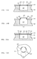
- FIGS. 13 a and 13 b are cross sectional views of the fully expanded and user actuated states, respectively, of the particular region;
- FIGS. 14 a and 14 b are cross-sectional views of the second variation of the second preferred embodiment with a pocket within the layer in the retracted and extended state
- FIGS. 15 a and 15 b are cross-sectional and top views, respectively, of the second variation of the second preferred embodiment with a pocket through the thickness of the layer;
- FIGS. 16 a and 16 b are cross-sectional views of the third variation of the second preferred embodiment in the retracted and extended states, respectively;
- FIGS. 17 a and 17 b are cross-sectional views of the first variation of the third preferred embodiment in the retracted and extended states, respectively;
- FIGS. 18 a and 18 b are cross-sectional views of the second variation of the third preferred embodiment in the retracted and extended states, respectively.
- FIGS. 19 and 20 are top views of examples of the second variation of the third preferred embodiment.
- FIGS. 21 a and 21 b are cross-sectional views of a support member between the layer and the substrate, with the cavity in a retracted volume setting and an expanded volume setting, respectively.
- FIG. 21 c is a top view of the support member.
- FIG. 21 d is a cross-sectional view of an alternative support member that partially defines the cavity.
- FIGS. 22 a -22 d are elevation views of variations of the preferred system.
- FIGS. 23 a -23 c are elevation views of one variation of the preferred system.
- FIGS. 24 a and 24 b are elevation views of one variation of the preferred system.
- FIGS. 25 a and 25 b are elevation views of one variation of the preferred system.
- the user interface system 100 of the preferred embodiment includes: a layer 110 defining a surface 115 , a substrate 120 supporting the layer 110 and at least partially defining a cavity 125 , a displacement device 130 coupled to the cavity 125 and adapted to expand the cavity 125 thereby deforming a particular region 113 of the surface 115 , and a touch sensor 140 that detects inputs from the user.
- the perimeter of the particular region 113 is at least partially defined by one or more attachment points 112 .
- the user interface system 100 may also include a display 150 coupled to the bottom surface of the substrate 120 and adapted to output images to the user.
- the user interface system 100 of the preferred embodiments has been specifically designed to be used as the user interface for an electronic device, more preferably in an electronic device that benefits from an adaptive user interface.
- the electronic device which may or may not include a display, is preferably an automotive console, a desktop computer, a laptop computer, a tablet computer, a television, a radio, a desk phone, a mobile phone, a PDA, a personal navigation device, a personal media player, a camera, a watch, a remote, a mouse, a trackpad, or a keyboard.
- the user interface system 100 may, however, be used as the user interface for any suitable device that interfaces with a user in a tactile and/or visual manner. As shown in FIG.
- the surface 115 of the user interface system 100 preferably remains flat until a tactile guidance is to be provided at the location of the particular region 113 .
- the surface 115 of the user interface system 100 may also be deformed when a user input is required.
- the displacement device 130 expands the cavity 125 to expand the particular region 113 , forming a deformation that may be felt by a user, and providing tactile guidance for the user.
- the expanded particular region 113 preferably also provides tactile feedback when the user applies force onto the particular region 113 to provide input.
- any other arrangement of the user interface system 100 suitable to providing tactile guidance and/or detecting user input may be used.
- the cavities 125 of the preferred embodiment functions to hold a fluid and to have at least two volumetric settings: a retracted volume setting (shown in FIG. 3 a ) and an expanded volume setting (shown in FIG. 3 b ), both of which are actuated by the displacement device 130 .
- a retracted volume setting shown in FIG. 3 a
- an expanded volume setting shown in FIG. 3 b
- the user may inwardly deform (or “actuate”) the particular region 113 to provide a user input (shown in FIG. 3 c ).
- the fluid is preferably a liquid (such as water, glycerin, or ethylene glycol), but may alternatively be a gas (such as air, nitrogen, or argon) or any other substance (such as a gel or aerogel) that expands the cavity 125 and deforms the surface 115 .
- a gas such as air, nitrogen, or argon
- any other substance such as a gel or aerogel
- the deformation of the particular region 113 functions to provide tactile guidance and/or tactile feedback on the surface 115 for the user.
- the deformation of the particular region 113 also preferably functions to inform the user of the type of input the deformation represents.
- the deformation of the particular region 113 may be of a shape that indicates the type of input that the deformation represents.
- the sheet 110 may include tactile instructions, for example, a pattern of beads or substantially small protrusions that may be felt by the user on the particular region 113 that indicate the type of input the deformation represents.
- the tactile instructions on the particular region 113 may alternatively be any other type of feature that is able to be felt tactilely by the user.
- the layer 110 and the substrate 120 of the preferred embodiment function to cooperatively define the cavity 125 .
- the layer 110 and substrate 120 are preferably similar to the layer and substrate disclosed and taught in U.S. application Ser. No. 12/319,334, but may alternatively be any suitable type.
- the layer 110 is preferably more pliable than the substrate 120 such that, as the cavity 125 expands, the layer 110 deforms while the substrate 110 remains relatively undeformed. If the user interface system 100 includes a display 150 , then the layer 110 and the substrate 120 are preferably both relatively transparent to allow the images displayed by the display 150 to be seen through the layer 110 and the substrate 120 .
- the layer 110 and the substrate 120 may also be index matched to allow light transmitted through without interruption. However, the layer 110 and the substrate 120 may be of any other suitable property.
- the layer 110 is preferably directly coupled to the substrate 120 .
- the user interface system 100 may include an additional layer 111 that is in arranged in between the layer 110 and the substrate 120 .
- the additional layer 111 may function as a support layer that includes perforations that allow for the fluid to expand the cavity 125 and deform the layer 110 and the particular region of the surface 113 .
- the attachment point 112 is preferably arranged to couple the layer 110 to the additional layer 111 .
- the additional layer 111 may deform with the layer 110 and the particular region of the surface 110 .
- the attachment point 112 is preferably arranged to couple the additional layer 111 to the substrate 120 .
- any other suitable arrangement of the layer 110 , the substrate 120 , and the attachment point 112 may be used.
- the substrate 120 may include a lattice-like support member 119 under the particular region of the surface 115 .
- the support member 119 functions to prevent a user from “pressing too far” into the deformation below the plane of the surface 115 .
- the support member 119 functions to reduce (or potentially eliminate) the user from feeling “divots” in the surface 115 when swiping a finger across the surface 115 . As shown in FIG.
- the support member 119 preferably includes holes or channels that allow for the expansion of the cavity 125 and the deformation of the surface 115 .
- the support member 119 is preferably integrally formed with the substrate 124 , but may alternatively be formed with the layer 110 or may be separately formed and later attached to the substrate 120 .
- the support member 119 may alternatively partially define the cavity 125 .
- the substrate 120 is preferably rigid, but may alternatively be flexible in one or more directions.
- the substrate 120 —if located above the display 150 —is preferably optically transparent, but may—if located below the display 150 or if bundled without a display 150 —be translucent or opaque.
- the substrate 120 is preferably made from a material including polymers or glass, for example, elastomers, silicon-based organic polymers such as poly-dimethylsiloxane (PDMS), thermoset plastics such as polymethyl methacrylate (PMMA), and photocurable solvent resistant elastomers such as perfluropolyethers.
- the substrate 120 may, however, be made of any suitable material that supports the layer 110 and at least partially defines the cavity 125 .
- the substrate 120 is a single homogenous layer approximately 1 mm to 0.1 mm thick and can be manufactured using well-known techniques for micro-fluid arrays to create one or more cavities and/or micro channels.
- the substrate 120 may be constructed using multiple layers from the same material or from different suitable materials.
- the touch sensor 140 of the preferred embodiment functions to detect the presence of a user input proximate to the particular region 113 of the surface 115 .
- the touch sensor 140 preferably detects the presence of a user touch by detecting a force that inwardly deforms the deformed particular region 113 or any other portion of the surface 115 , but may alternatively detect the presence of a user touch by detecting the presence of the finger at a location proximate to the particular region 113 .
- the touch sensor 140 may be a capacitive sensor, a resistive sensor, a pressure sensor, or any other suitable type of sensor.
- the shape of the deformation of the particular region 113 is preferably one that is felt by a user through their finger (or multiple fingers).
- the shape of the deformation of the particular region 113 preferably acts as and provides the feeling of a button that can be pressed by the user, such as a keyboard (shown in FIGS. 4, 5 a , and 5 b ).
- the shape preferably acts and provides the feeling of a slider that can be pressed by the user in one location along the slider or that can be swept in a sliding motion along the slider, such as the “click wheel” of the Apple iPod—second generation (shown in FIG. 6 ).
- the shape preferably acts and provides the feeling of a pointing stick that can be pressed by the user from multiple directions and/or locations along the surface whereby the user is provided with tactile feedback that distinguishes a first directional touch from a second directional touch and/or a touch in a first location from a touch in a second location, such as the pointing stick marketed by IBM as the TRACKPOINT and by Synaptics as the TOUCHSTYK, which are both informally known as the “nipple”.
- the deformation may, however, act as any other suitable device or method that provides suitable tactile guidance and feedback.
- the shape of the deformation of the particular region 113 also preferably functions to minimize the optical distortion of the image underneath the deformed particular region 113 .
- the shape of the deformation of the particular region 113 is preferably controlled using one of three preferred embodiments.
- the shape is controlled by the location of the attachment points 112 of the layer 110 to the substrate 120 .
- the shape is controlled by the geometry of the layer 110 in relation to the attachment points 112 .
- the shape is controlled by the material composition of the layer 110 in relation to the attachment points 112 .
- the invention is preferably of one of the three aforementioned embodiments, but may alternatively be any combination or permutation of the three aforementioned embodiments.
- the shape of the deformation of the particular region 113 may also be thought of as the result of a formula or combination of characteristics of the particular region 113 of the surface, such as the thickness of the material, the geometry of the material, the modulus of elasticity of the material, and the pressure applied to the particular region 113 , and/or the location of the attachment points 112 .
- any other suitable method for controlling the shape of the deformation of the particular region 113 may be used, for example, the shape of the deformation of the particular region 113 may be changed by adjusting the pressure provided by the displacement device 130 to expand the cavity 125 .
- the first preferred embodiment utilizes the location of the attachment points 112 to control the shape of the distortion of the particular region 113 .
- the perimeter of the particular region 113 is at least partially defined by the attachment points 112 .
- the attachment point 112 defines a “transition point” between a first portion of the layer 110 located on a first side of the attachment point 112 that experiences significant deformation (the particular region 113 ) and a second portion of the layer 110 located on a second side of the attachment point 112 that experiences little or no deformation.
- the attachment points 112 are preferably a series of continuous points that define an edge, but may alternatively be a series of non-continuous points.
- the attachment points 112 are preferably defined during the attachment process of the layer 110 to the substrate 120 .
- the layer 110 may be attached to the substrate 120 using an adhesive, heat treatment, ultra-sonic bonding, oxygen plasma surface treatment, or any other techniques known to one skilled in the art.
- a particular region of the layer 110 is left unattached from the substrate 120 .
- the attached region of the layer 110 directly adjacent to this unattached region is defined as the attachment points 112 .
- the attachment points 112 may also be defined during the manufacturing of the layer 110 and the substrate 120 .
- the substrate 120 may be manufactured with attachment geometry (e.g. a hole) and the layer 110 may be manufactured with a reciprocating attachment geometry (e.g. a post).
- attachment geometry is engaged, attaching the layer 110 to the substrate 120 and defining the attachment points 112 .
- any other method suitable to defining the attachment points 112 may be used.
- the attachment points 112 preferably define the perimeter of the particular region 113 into a shape selected from (1) a substantially circular region (shown in FIG. 4 ) that preferably results in a dome-like deformation, (2) a rectangular region (shown in FIG. 5 ) that preferably results in a ridge-like deformation, (3) a square region (not shown) that preferably results in a square shaped deformation, such as those seen in keyboards, (4) a ring-like region (as shown in FIG. 6 ) that preferably results in a ridge-like deformation in the form of a ring, and/or any other suitable shape for the particular region 113 .
- a substantially circular region shown in FIG. 4
- a rectangular region shown in FIG. 5
- a square region not shown
- a ring-like region as shown in FIG. 6
- the particular region 113 is deformed.
- the particular region 113 is preferably adjacent to the cavity 125 and/or partially defines the cavity 125 , allowing deformation of the cavity 125 to directly deform the particular region 113 , but may alternatively be located in any other suitable location. Because the particular region 113 is located adjacent to the cavity 125 , the location of the attachment points 112 relative to the cavity 125 have a direct effect on the shape of the deformation of the particular region 113 . As shown in FIGS. 7 a and 7 b , the attachment points 112 at first positions that are closer to the center of the cavity 125 may lead to a dome-like deformation with a first diameter along the surface 115 . As shown in FIGS.
- attachment points 112 at second positions that are farther away from the center of the cavity 125 than the first positions may lead to a dome-like deformation with a second diameter along the surface 115 that is larger than the first diameter.
- attachment points 112 at third positions that are closer to the center of the cavity 125 than the first positions may lead to a dome-like deformation with a third diameter that is smaller than the first diameter.
- the described attachment points may also lead to dome-like deformations with a first, second, and third height respectively and/or a first, second and third curvature respectively that may be adjusted by varying the level of deformation caused by the displacement device 130 .
- the tactile feedback felt by the user from the particular region 113 in the variation shown in FIGS. 8 a and 8 b is of a softer surface than that felt in the variation shown in FIGS. 9 a and 9 b.
- the attachment points 112 may also be located along the wall of the cavity 125 at an “depth” lower than the rest of the layer 110 .
- the attachment points 112 are preferably symmetric relative to the center of the cavity 125 , but may alternatively be asymmetric relative to the center of the cavity 125 .
- the attachment point 112 may be located in any other location and/or arrangement suitable to achieve the desired shape and feel for the deformation of the particular region 113 .
- the second preferred embodiment utilizes geometry of the layer 110 in relation to the attachment points 112 to control the shape of the deformation of the particular region 113 .
- the attachment points 112 of the second preferred embodiment are preferably similar or identical to those of the first preferred embodiment.
- the geometry of the layer 110 in relation to the attachment points 112 preferably create regions of higher pliability and regions of lower pliability. As the cavity 125 is expanded, the particular region 113 is deformed to accommodate for the adjusted volume and pressure.
- the regions of higher pliability will deform (e.g. stretch, bend, and/or compress) more while the regions of lower pliability will deform less.
- the implementation of certain combinations of regions of relatively higher pliability and regions of relatively lower pliability along the layer 113 allows for the control of the shape of the deformation of the particular region 113 . Implementation of such regions is preferably achieved in one of several variations.
- the layer 110 includes a first portion 210 with a first thickness and a second portion 220 with a second thickness that is less than the first thickness.
- the surface 115 is preferably planar, thus the thickness is preferably “removed” from the side of the layer 110 opposite of the surface 115 , but may be “removed” from any other suitable portion of the layer 110 that does not cause the side of the layer 110 that defines the surface 115 to be noticeably non-planar.
- the layer 110 is preferably of a homogenous or uniform material.
- the layer 110 may also include a third portion (not shown) of a third thickness that is less than the first thickness, but greater than the second thickness.
- the third portion may alternatively be of a varying thickness and functions as a transitional region between the first portion 210 and the second portion 220 .
- the third portion may alternatively function to provide additional control of the shape of the deformation of the particular region 113 .
- the third portion may function to form a concave top surface, providing the user with a tactile indication of where to place their finger, similar that seen on a key of a keyboard.
- the second portion 220 effectively acts as a material with higher pliability than the first portion 210 and substantially biases the particular region 113 to deform at a higher degree at the second portion 220 than at the first portion 210 .
- the second portion 220 of the layer 110 may be located adjacent to the attachment points 112 (shown in FIG. 10 a ), resulting in a higher degree of deformation at the attachment points 112 (shown in FIG. 10 b ), but may alternatively be located closer to the center of the cavity 125 than the attachment points 112 , as shown in FIG. 11 a , resulting in a lesser degree of deformation at the attachment points 112 and a higher degree of deformation at the second portion 220 of the layer 110 , as shown in FIG. 11 b .
- the second portion 220 of the layer 110 may be located in any other suitable location where a higher degree of deformation is desired.
- the user may feel the pliability differences between the first portion 210 and the second portion 220 .
- the surface of the substrate 120 that interfaces with the layer 110 may include a mating geometry 225 to support the layer 110 at the second portion 220 and decrease the difference felt by the user between the first and second portions 210 and 220 , as shown in FIG. 10 a and 10 b .
- the combination of the first portion 210 and the second portion 220 may also result in a deformation shape that is no longer a typical dome-like shape.
- the resulting shape is preferably a button with a relatively flat top. If the user interface system 100 is provided with a display 150 , this may be advantageous in preventing the optical distortion of an image that is displayed on a display 150 underneath the particular region 113 .
- a plurality of first and second portions 210 and 220 may be included in the layer 110 , which results in a deformation shape of a nub with bellows, as shown in FIG. 12 b .
- This shape may be useful in the application of a pointing stick by allowing for a higher degree of tactile feedback (e.g. from the elastic response of the plurality of second portion 220 S) when the user pushes the deformation in a variety of directions.
- any other suitable arrangement of the thinner second portion 220 S may be used.
- first and second portion 220 S may be used to create a “living” or “natural” hinge, such as those seen in commonly used snap top bottle caps.
- the natural hinge for the deformation of the particular region 113 preferably allows for two states, an extended state and a retracted state.
- the particular region is preferably in the retracted state.
- the particular region 113 is preferably transitioned into an expanded state.
- the particular region 113 is also preferably returned to the retracted state.
- the “living” or “natural” hinge may function to provide a third state to the deformation of the particular region 113 .
- the expanded state of the deformation of the particular region 113 may include two states: the fully expanded state (as shown in FIG. 13 a ) and the user actuated state (as shown in FIG. 13 b ).
- the fully expanded state functions to provide the user with tactile guidance
- the actuated state functions to provide the user with the tactile indication that the user has applied a force to the system.
- the user actuated state is preferably of an expansion that is in between the retracted state and the fully expanded state.
- the deformed particular region preferably returns to the fully actuated state until the cavity 125 is no longer expanded.
- the expanded state of the deformation of the particular region 113 is a bi-modal geometry. This may be applied in user scenarios wherein the user interface system 100 provides tactile guidance for a “clickable” button (e.g. a keyboard key).
- the thinner second portion 220 is preferably created during the manufacturing process of the layer 110 .
- the layer 110 may be molded to contain the first portion 210 , thinner second portion 220 , and/or the third portion.
- the thinner second portion 220 may also be created after the layer 110 has been made.
- the layer 110 may be molded as a continuous sheet with uniform thickness.
- the thinner second portion 220 is then created through a cutting process that removes an amount of thickness from the second portion 220 of the layer 110 .
- any other suitable method and/or process to create the second portion 220 may be used.
- the layer 110 preferably includes a second portion 220 that defines a pocket (or “void”) within the layer 110 and a first portion 210 that is continuous and does not define a cavity.
- the layer 110 is preferably made of a uniform material.
- the layer 110 may also include a third portion that defines a pocket smaller than the pocket of the second region 220 .
- the third portion may alternatively define a pocket of varying size and functions as a transitional region between the first portion 210 and the second portion 220 .
- the third portion may alternatively function to provide additional control of the shape of the deformation of the particular region 113 .
- the third portion may function to form a concave portion of the square, providing the user with a tactile indication of where to place their finger, similar that seen on a key of a keyboard.
- the second portion 220 effectively acts as a material with higher pliability than the first portion 210 and substantially biases the particular region 113 to deform at a higher degree at the second portion 220 than at the first portion 210 , as shown in FIGS. 14 a and 14 b .
- the second portion 220 of the second variation preferably functions similarly or identically to the second portion 220 of a second thickness in the first variation.
- the pocket is preferably defined during the manufacturing process of the layer 110 , for example, the layer 110 may be manufactured using a plurality of thin-layers that are stacked. Thin-layers that are placed towards the middle of the layer 110 preferably define a hole while thin-layers that are placed on the top and bottom of the layer 110 are preferably continuous (e.g. do not define a hole). When stacked, the completed layer 110 will contain the second portion 220 that defines a pocket.
- the pocket may alternatively be defined in a post-manufacturing process, for example, a heat treatment in a particular location along the layer 110 that causes the material of the layer 110 to shrink at the particular location, causing a pocket to form internally.
- the pocket may also be filled with a fluid, gel, or any other suitable material that has a refractive index that is substantially identical to that of the sheet 110 . This will allow the second portion 220 to be a region of higher pliability while remaining substantially invisible to the user. However, any other method and/or process suitable to creating the pocket may be used. Additionally, similar to the first variation, the layer 110 may include a plurality of first and second portions 210 and 220 to create a desired shape for the deformation of the particular region 113 .
- the pocket may extend through the entire thickness of the layer 110 (thereby creating a “canyon”) and alternated with first portions that do not define a pocket.
- the pocket is preferably isolated from the cavity 125 , preferably by the additional layer 111 , but may alternatively be by any other suitable method.
- the additional layer 111 preferably functions to prevent leakage of the fluid from the cavity 125 through the layer 110 onto the surface 115 .
- the additional layer 111 is preferably continuous without any perforations, preventing the passage of the fluid through the additional layer 111 to the layer 110 where the fluid may leak through the pocket onto the surface 115 .
- the additional layer 111 may function to allow fluid to pass through proximal to the first portion 210 of the layer 110 that does not include pockets and to prevent fluid to pass through proximal to the second portion 220 of the layer 110 (for example, by forming a webbing between the additional layer 111 and the layer 110 that directs flow of fluid as desired), thus preventing fluid from leaking out the pockets to the surface 115 .
- the additional layer 111 may prevent leakage of fluid through the layer 110 to the surface 115 in any other suitable method.
- the pocket of this variation may also be defined using the layering method of thin-layers described above, but may alternatively be defined in a post-manufacturing process, for example, a stamping process.
- the layer 110 may be manufactured as a continuous sheet using any suitable method and then cut using a cutting die, creating a pocket through the thickness of the layer 110 .
- the cutting die may create a plurality of pockets at one time, but may alternatively create one pocket at a time. However, any other method and/or process suitable to creating the pocket may be used.
- the pocket of the second variation is preferably of a circular shape (e.g., spherical or cylindrical), but may alternatively be of an arc shape, a rectangular shape (e.g., a rectangular prism), or any other shape suitable to providing the desired geometry of the deformation of the particular region 113 .
- the layer 110 is preferably constructed of a material wherein the molecules, fibers, or an other suitable component of the material may be aligned in a particular direction to influence the overall pliability (i.e., elastic modulus) of the material, for example, the pliability of a polymer material.
- the layer 110 preferably includes a first portion 210 wherein the components of the material are aligned in a first direction and a second portion 220 wherein the components of the material are aligned in a second direction.
- the effective pliability of the layer 110 seen from the force applied by the deformed cavity 125 is preferably higher in the second portion 220 than the first portion 210 .
- the layer 110 is a polymer material
- polymers molecules that are aligned in a parallel fashion are less structurally resistant to force applied perpendicular to the molecules than a force applied along the direction of alignment.
- polymer molecules that are arranged in a lattice structure are also relatively structurally resistant to applied force. Because of these material properties, in this example, the molecules are aligned perpendicular to the force resulting from the deformation of the cavity 125 in the second portion 220 and parallel to the force resulting from the deformation of the cavity 125 and/or arranged in a lattice pattern in the first portion 210 (as shown in FIGS. 16 a and 16 b ).
- the layer 110 may also include a third portion wherein the molecules are aligned at an angle in between a perpendicular angle and a parallel angle to the force resulting from the deformation of the cavity 125 .
- This third portion preferably functions as a transitional region between the first portion 210 and the second portion 220 .
- the third portion may alternatively function to provide additional control of the shape of the deformation of the particular region 113 .
- the third portion may function to form a concave portion of the square, providing the user with a tactile indication of where to place their finger, similar that seen on a key of a keyboard.
- the second portion 220 effectively acts as a material with higher pliability than the first portion 210 and substantially biases the particular region 113 to deform at a higher degree at the second portion 220 than at the first portion 210 .
- the second portion of the third variation preferably functions similarly or identically to the second portion of a second thickness in the first variation.
- any other arrangement of the components of the material of the layer 110 suitable to establishing a first and second portion may be used.
- the layer 110 may include a plurality of first and second portions 210 and 220 to create a desired shape for the deformation of the particular region 113 .
- the third preferred embodiment utilizes the material composition of the layer 110 in relation to the attachment points 112 to control the shape of the deformation of the particular region 113 .
- the attachment points 112 of the third preferred embodiment are preferably similar or identical to those of the first preferred embodiment.
- the material composition of the layer 110 in relation to the attachment points 112 preferably create regions of higher pliability and regions of lower pliability. As the cavity 125 is expanded, the particular region 113 is deformed to accommodate for the adjusted volume and pressure.
- the regions of relatively higher pliability will deform (e.g. stretch, bend, and/or compress) more while the regions of relatively lower pliability will deform less.
- the implementation of certain combinations of these regions along the layer 113 allows for the control of the shape of the deformation of the particular region 113 . Implementation of such regions of relatively higher pliability and regions of relatively lower pliability is preferably achieved in one of several variations.
- the layer 110 may include a first portion 210 of a first type of material and a second portion 220 of a second type of material.
- the second type of material preferably has a higher pliability than the first type of material, resulting in higher pliability of the second portion 220 than the first portion 210 .
- the second portion 220 of this first variation of the third preferred embodiment preferably functions similarly or identically to the second portion 220 of the first variation of the second preferred embodiment.
- the first and second portions 210 and 220 are preferably assembled during the manufacturing of the layer 110 .
- the layer 110 may be created using a double injection molding process such that the first and second types of material are bonded during the injection molding process.
- any other manufacturing method suitable to combine two types of material may be used.
- the first and second portions 210 and 220 may alternatively be assembled in a post-manufacturing process.
- the first portion 210 and the second portion 220 may be manufactured independently and then bonded together using adhesive, heat treatment, ultra-sonic boding, oxygen plasma surface treatment, or any other techniques known to one skilled in the art.
- any other suitable manufacturing method may be used.
- the layer 110 may include a plurality of first and second portions 210 and 220 to create a desired shape for the deformation of the particular region 113 .
- the layer 110 is preferably made of a base material 230 and includes a modifier material 232 that changes the pliability properties of the layer 110 (for example, lower pliability).
- the modifier material 232 preferably changes the pliability of the base material 230 by providing a physical structure that mechanically interacts with and affects the pliability of the base material, for example, by providing a scaffold or a support structure across the base material 230 and decreasing pliability in locations of the layer 110 which include the modifier material 232 .
- the modifier material 232 may change the pliability of the base material 230 by chemically interacting with the base material, for example, the modifier material 232 chemically reacts with the base material 230 to form a third material of lower pliability than the base material.
- the chemical reaction preferably occurs during the manufacturing process, but may alternatively occur post-manufacturing, for example, the user may activate the reaction electrically or mechanically.
- the modifier material 232 may modify the pliability of the base material 230 in any other suitable manner.
- the modifier material 232 is embedded into a first portion 210 of the layer 110 , decreasing the pliability at the first portion 210 , and a second portion 220 that includes only the base material.
- the modifier material 232 may be embedded into the second portion 220 of the layer 110 to increase pliability and the first portion 210 is without the modifier material 232 .
- the modifier material 232 may include a secondary material 234 and a tertiary material 236 , as shown in FIG. 19 , where the combination of the secondary material and the tertiary material changes the pliability properties of the layer 110 .
- the secondary material 234 may be arranged lengthwise along the layer 110 and the tertiary material 236 may be arranged widthwise along the layer 110 and secondary and tertiary materials 234 and 236 overlap at an intersection 235 .
- the secondary material 234 and the tertiary material 236 combine to form an area of different pliability characteristics (for example, higher pliability).
- the intersection 235 is located within the particular region 113 and forms a second portion 220 of increased pliability, but the intersection 235 may alternatively form a first portion 210 of decreased pliability.
- the second example of the modifier material 232 may be of a material type that changes pliability in a direct relationship with the amount of material present, for example, a material where the thickness of the material determines pliability.
- a portion of the modifier material 232 may be arranged lengthwise along a the layer 110 and a second portion of the modifier material 232 may be arranged widthwise along the layer 110 wherein the first and second portions of the modifier material 232 overlap at an intersection 235 .
- a region with a substantially higher content of the modifier material 232 forms, changing the pliability characteristics of the region.
- the region wherein the secondary and tertiary materials 234 and 236 are not combined or where the content of the modifier material 232 is lower may also have a different pliability characteristic from the base material.
- any other suitable arrangement of modifier material 232 may be used.
- the modifier material 232 may be the same material as the base material.
- the pliability of the base material 230 may be adjusted when treated with a treatment such as heat treatment or ultraviolet treatment.
- a treatment such as heat treatment or ultraviolet treatment.
- the polymer chains of a polymer based base material 230 may cross link when exposed to ultraviolet light, thus decreasing the pliability of the cross linked portions of the base material 230 .
- a mask may be placed over the second portion 220 prior to an ultraviolet treatment.
- the regions without the mask will become first portions 210 with lower pliability and the regions with the mask will remain relatively more pliable.
- the base material 230 may be coated to prevent further cross-linking of the polymer chains when exposed to ultraviolet light.
- any other suitable method may be used to adjust the pliability of particular portions of a base material 230 with adjustable pliability.
- the modifier material 232 may be of a material substantially similar to the base material 230 (e.g., a polymer of a second type embedded into a polymer of a first type) or may alternatively be of a material substantially dissimilar from the base material 230 (e.g., a metallic material embedded into a polymer material).
- the modifier material 232 that includes a secondary material and a tertiary material
- the secondary and tertiary materials may be of a material substantially similar or identical to each other and/or the base material.
- the secondary, tertiary, and base materials may be of substantially different types of materials.
- the modifier material 232 may be arranged into a variety of patterns and/or geometries, such as a lattice structure (as shown in FIG. 20 ), a plate structure, a plurality of strips, a ring structure, a plurality of concentric rings, a hexagonal structure, a rectangular structure, or any other suitable structure to control the shape of the deformation of the particular surface 113 .
- a plurality of modifier material 232 may also be embedded at different levels within the thickness of the layer 110 .
- the embedded modifier material 232 preferably functions to decrease the overall pliability of the first portion 210 , allowing the first portion 210 to effectively act as a material with lower pliability than the second portion 220 , substantially biasing the particular region 113 to deform at a higher degree in the second portion 220 than at the first portion 210 .
- the embedded modifier material 232 may function to increase the overall pliability of the second portion 220 .
- the modifier material 232 is preferably embedded into the first portion 210 or the second portion 220 during the manufacturing process of the layer 110 .
- the modifier material 232 may be placed within a mold for the layer 110 and embedded into the layer 110 at the first portion 210 during the molding process.
- the layer 110 may be manufactured using a layering process wherein thin-layers are stacked. During the stacking process of the thin-layers, the modifier material 232 may be placed in the first portion 210 and embedded into the layer 110 during the thin-layer stacking process.
- the layer 110 may consist of at least two thin-layers wherein the thin-layers are each manufactured independently and then assembled with the modifier material 232 placed in between the thin-layers in a suitable arrangement.
- the thin-layers may then be attached or bonded using adhesive, heat treatment, ultra-sonic bonding, oxygen plasma surface treatment, or any other techniques known to one skilled in the art.
- the modifier material 232 may be formed into the suitable arrangement and then inserted in between two layers of base material. The pre-formed modifier material 232 may then be bonded or attached to the base material.
- the modifier material 232 may alternatively be embedded into the first portion 210 after the layer 110 has been made.
- the layer 110 may be molded to define a niche in the first portion 210 .
- the modifier material 232 is then assembled into the niche and sealed with a sealing material that is preferably substantially similar to the base material 230 (for example, a plug made of the base material 230 that is bonded to the layer 110 ) but may alternatively be of a sealing material substantially dissimilar from the base material 230 (for example, an adhesive or a sealant).
- the layer 110 may also be molded as a continuous layer, wherein a post-manufacturing process creates a niche at the first portion 210 of the layer 110 , allowing the modifier material 232 to be assembled into the niche through a process similar to that mentioned above.
- the assembled modifier material 232 and base material 230 of the layer 110 may be put through a heat treatment, an ultraviolet treatment, or any other suitable treatment to activate the chemical reaction between the modifier material 232 and the base material.
- any other suitable method and/or process suitable to embedding a secondary material into the first portion 210 of the layer 110 may be used.
- the tactile layer 110 of the preferred system 100 functions to provide tactile guidance to a user through a deformable region 113 that is tactilely distinguishable from an undeformable region, at the tactile surface 115 of the tactile layer 110 , in at least one of the retracted and expanded settings.
- the tactile layer 110 may be of any form and any thickness across the deformable region 113 and the undeformable region.
- the undeformable region of the tactile layer 110 is substantially uniform in thickness, and a portion of the deformable region 113 is of a uniform thickness greater than the thickness of the undeformable region.
- the portion of the deformable region 113 of greater thickness may substantially resist flexing as compared to a thinner portion of the deformable region 113 such that the tactile surface 115 at the deformable region 113 is substantially planar in both the retracted and expanded settings.
- FIGS. 25 a and 25 b the portion of the deformable region 113 of greater thickness may substantially resist flexing as compared to a thinner portion of the deformable region 113 such that the tactile surface 115 at the deformable region 113 is substantially planar in both the retracted and expanded settings.
- the undeformable region of the tactile layer 110 is substantially uniform in thickness, and the deformable region 113 is of a varying thickness including portions of thickness greater than the thickness of the undeformable region.
- the deformable region 113 is preferably planar at the tactile surface 115 in the retracted setting and defines a greater thickness near the center of the deformable region 113 than at the perimeter of the deformable region 113 such that the tactile surface 115 of the deformable region 113 may also be substantially planar in both the retracted and expanded settings.
- the deformable region 113 may define a “step” at a border between the deformable and undeformable regions. This step may be rectilinear or curvilinear in form, or of any other form.
- the deformable region 113 may extend into the cavity 125 to contact a wall of the cavity 125 in the retracted state.
- the wall of the cavity may define the support member 119 , which may limit inward deformation of the deformable region 113 due to a force applied to the tactile surface 115 .
- the extension of the deformable region 113 into the cavity 125 may be cubic, rectilinear, hemispherical, cylindrical (shown in FIG. 25 a ), conical (shown in FIG.
- the face(s) of the extension are preferably inset from the face(s) of the cavity 125 to permit the extensions to move unobstructed within the cavity 125 as the deformable region 113 transitions between the retracted and expanded settings.
- the extension may be tetrahedral or conical in form, wherein at least one wall of the cavity 125 is inclined at a first angle (a “draft” angle) and the extension of the deformable region 113 includes a wall of an included angle matched with the angle of the inclined wall of the cavity 125 .
- the inclined face of the extension of the deformable region 113 preferably contacts the inclined wall of the cavity 125 in the retracted setting, wherein the wall of the cavity 125 defines the support member 119 that supports the deformable region 113 against inward deformation in the presence of a force on the tactile surface 115 .
- the extension may be of any other form and the cavity may include a face of any other form matched with the extension.
- the extension and/or the cavity may include a latching feature, as shown in FIGS. 22 a -22 d .
- the latching feature is preferably a mechanical construction within the tactile layer 110 and/or the substrate 120 that provides tactile feedback, such as in the form of a “click,” when the deformable region 113 is depressed. In one example implementation shown in FIGS.
- the cavity includes a ridge and the extension of the tactile layer 110 includes a lip such that at least one of the lip and the ridge deform as the deformable region 113 is depressed into the cavity, wherein deformation of the lip and/or ridge results in a “click.”
- the geometry of the lip and ridge can latch the position of the deformable region until a second force is applied, such as by changing fluid pressure within the cavity 125 (e.g., with the displacement device 130 ) or by depressing the deformable region.
- the cavity includes a ridge and the extension of the tactile layer 110 includes a lip such that at least one of the lip and the ridge deform as the deformable region 113 is depressed into the cavity, wherein deformation of the lip and/or ridge results in a “click.”
- the ridge of the cavity is coupled to a bladder or second cavity, wherein displacement of fluid into or out of (or increase or decrease is fluid pressure in) the bladder or second cavity moves the lip into and out of the cavity, respectively, to adjust interference between the lip and the ridge.
- the ridge can be moved toward the lip to yield a firmer click, and the ridge can be moved away from the lip to yield a softer click or to unlatch the deformable region 113 .
- the cavity 125 can include one or more ridges coupled to one or more bladders or second cavities, and the one or more bladders or second cavities can be coupled to the displacement device 130 , can be coupled to an independent displacement device, and/or can be controlled by any number of valves.
- the extension of the deformable region 113 includes a piston that engages a cylinder in the cavity 125 .
- the extension further includes a lip and the cavity 125 further includes a ridge, as described above.
- the cavity 125 and cylinder are filled with the fluid, and as the deformable region is depressed from a first position to a second position, fluid is trapped in the cylinder and compressed by the piston. Once released, the deformable region 113 returns to the first position as the compressed fluid in the cylinder acts as a return spring. Because the lip and/or ridge preferably deform to generate a “click” when the deformable region is depressed from the first position to the second position, and because the lip and/or ridge preferably deform to generate a second “click” when the deformable region returns to the first position, the example implementation can yield tactile feedback that is a double click.
- the piston and cylinder of this example implementation can also be applied to any of the foregoing example implementations or variations.
- the tactile layer 110 , substrate 120 , and/or any other elements of the preferred system 100 can include any other feature or geometry to provide tactile feedback to a user when the deformable region 113 is depressed.
- the attachment surface may extend into the cavity 125 , wherein the deformable region 113 is coupled to the attachment surface at one or more locations within the cavity 125 , as shown in FIGS. 9 a and 9 b .
- the deformable and undeformable regions may be of any other form and interface with the cavity 125 and/or support member 119 in any other way; the support member 119 may also be of any other form and operate in any other way to limit inward deformation of the deformable region 113 due to a force applied to the tactile surface 115 .
- the tactile layer 110 includes a recess, opposite the tactile surface 115 , that substantially defines the fluid channel.
- the tactile layer 110 is preferably coupled to the substrate 120 that is uniform (e.g., continuous) across a face adjacent the tactile layer 110 .
- the fluid channel can be enclosed by substrate 120 , and the substrate 120 can be physically coextensive with any other the display or touch sensor, which can yield the benefit of reducing the component count of the preferred user interface 100 .
- the tactile layer 110 is preferably selectively bonded to the substrate 120 , wherein a bonded region of the tactile layer 110 defines the undeformable region and a region not bonded to the substrate 120 define the deformable region.
- the tactile layer 110 , substrate 120 , and fluid channel can be of any other form or geometry.
Abstract
Description
Claims (14)
Priority Applications (1)
| Application Number | Priority Date | Filing Date | Title |
|---|---|---|---|
| US14/486,743 US9612659B2 (en) | 2008-01-04 | 2014-09-15 | User interface system |
Applications Claiming Priority (7)
| Application Number | Priority Date | Filing Date | Title |
|---|---|---|---|
| US11/969,848 US8547339B2 (en) | 2008-01-04 | 2008-01-04 | System and methods for raised touch screens |
| US12/319,334 US8154527B2 (en) | 2008-01-04 | 2009-01-05 | User interface system |
| US22300209P | 2009-07-03 | 2009-07-03 | |
| US12/652,708 US8199124B2 (en) | 2009-01-05 | 2010-01-05 | User interface system |
| US13/414,589 US9274612B2 (en) | 2008-01-04 | 2012-03-07 | User interface system |
| US13/481,676 US8922510B2 (en) | 2008-01-04 | 2012-05-25 | User interface system |
| US14/486,743 US9612659B2 (en) | 2008-01-04 | 2014-09-15 | User interface system |
Related Parent Applications (1)
| Application Number | Title | Priority Date | Filing Date |
|---|---|---|---|
| US13/481,676 Continuation-In-Part US8922510B2 (en) | 2008-01-04 | 2012-05-25 | User interface system |
Publications (2)
| Publication Number | Publication Date |
|---|---|
| US20150029123A1 US20150029123A1 (en) | 2015-01-29 |
| US9612659B2 true US9612659B2 (en) | 2017-04-04 |
Family
ID=52390063
Family Applications (1)
| Application Number | Title | Priority Date | Filing Date |
|---|---|---|---|
| US14/486,743 Expired - Fee Related US9612659B2 (en) | 2008-01-04 | 2014-09-15 | User interface system |
Country Status (1)
| Country | Link |
|---|---|
| US (1) | US9612659B2 (en) |
Cited By (3)
| Publication number | Priority date | Publication date | Assignee | Title |
|---|---|---|---|---|
| US20160085380A1 (en) * | 2014-09-22 | 2016-03-24 | Hyundai Motor Company | Acoustic user interface apparatus and method for recognizing touch and rubbing |
| US10176942B2 (en) * | 2016-10-28 | 2019-01-08 | Microjet Technology Co., Ltd. | Liftable keyboard |
| US11235351B2 (en) * | 2017-04-24 | 2022-02-01 | Commissariat A L'energie Atomique Et Aux Energies Alternatives | Time reversal interface generating an acoustic lubrication |
Families Citing this family (2)
| Publication number | Priority date | Publication date | Assignee | Title |
|---|---|---|---|---|
| US9791929B2 (en) * | 2014-10-31 | 2017-10-17 | Elwha Llc | Tactile control system |
| DE102016223476A1 (en) * | 2016-11-25 | 2018-05-30 | BSH Hausgeräte GmbH | Haptic control for a household appliance |
Citations (504)
| Publication number | Priority date | Publication date | Assignee | Title |
|---|---|---|---|---|
| US3034628A (en) | 1960-10-31 | 1962-05-15 | Sperry Rand Corp | Pneumatic keyboard |
| US3659354A (en) | 1970-10-21 | 1972-05-02 | Mitre Corp | Braille display device |
| US3759108A (en) | 1971-09-16 | 1973-09-18 | Gen Electric | Single gauge multi-time constant and multi-tissue ratio automatic decompression instruments |
| US3780236A (en) | 1971-05-18 | 1973-12-18 | Gen Signal Corp | Push button switch assembly with slidable interlocking means preventing simultaneous operation of two or more pushbuttons |
| US3818487A (en) | 1972-08-24 | 1974-06-18 | W Brody | Soft control materials |
| US4109118A (en) | 1976-09-01 | 1978-08-22 | Victor Kley | Keyswitch pad |
| US4209819A (en) | 1978-03-13 | 1980-06-24 | Key Tronic Corporation | Capacitive keyswitch |
| US4290343A (en) | 1978-10-30 | 1981-09-22 | Mts Systems Corporation | High volume poppet valve with orifice opening speed control |
| US4307268A (en) | 1978-11-17 | 1981-12-22 | Rogers Corporation | Tactile element and keyboard including the tactile element |
| US4467321A (en) | 1982-04-30 | 1984-08-21 | Volnak William M | Chording keyboard for generating binary data |
| US4477700A (en) | 1983-11-14 | 1984-10-16 | Rogers Corporation | Tactile membrane keyboard with elliptical tactile key elements |
| US4517421A (en) | 1980-01-28 | 1985-05-14 | Margolin George D | Resilient deformable keyboard |
| US4543000A (en) | 1981-10-13 | 1985-09-24 | Hasenbalg Ralph D | Latching actuator |
| US4584625A (en) | 1984-09-11 | 1986-04-22 | Kellogg Nelson R | Capacitive tactile sensor |
| US4700025A (en) | 1986-05-23 | 1987-10-13 | Alps Electric Co., Ltd. | Transparent touch-sensitive panel |
| US4743895A (en) | 1984-04-05 | 1988-05-10 | Phosphor Products Co. Ltd. | Capacitive switches |
| JPS63164122A (en) | 1986-12-26 | 1988-07-07 | 日本メクトロン株式会社 | Transparent touch switch |
| US4772205A (en) | 1986-05-06 | 1988-09-20 | Siemens Aktiengesellschaft | Tactile braille or graphic display |
| US4920343A (en) | 1988-09-30 | 1990-04-24 | Honeywell Inc. | Capacitive keyswitch membrane with self contained sense-to-ground capacitance |
| US4940734A (en) | 1988-11-23 | 1990-07-10 | American Cyanamid | Process for the preparation of porous polymer beads |
| US4980646A (en) | 1988-03-30 | 1990-12-25 | The Trustees Of The University Of Pennsylvania | Impedance tomographic tactile sensor |
| US5194852A (en) | 1986-12-01 | 1993-03-16 | More Edward S | Electro-optic slate for direct entry and display and/or storage of hand-entered textual and graphic information |
| US5195659A (en) | 1991-11-04 | 1993-03-23 | Eiskant Ronald E | Discreet amount toothpaste dispenser |
| US5212473A (en) | 1991-02-21 | 1993-05-18 | Typeright Keyboard Corp. | Membrane keyboard and method of using same |
| US5222895A (en) | 1990-03-13 | 1993-06-29 | Joerg Fricke | Tactile graphic computer screen and input tablet for blind persons using an electrorheological fluid |
| US5286199A (en) | 1991-10-04 | 1994-02-15 | Siegfried Kipke | Electromechanical transducer |
| JPH06125188A (en) | 1992-10-12 | 1994-05-06 | Fujitsu Ltd | System for cooling electronic apparatus |
| US5346476A (en) | 1992-04-29 | 1994-09-13 | Edward E. Elson | Fluid delivery system |
| US5369228A (en) | 1991-11-30 | 1994-11-29 | Signagraphics Corporation | Data input device with a pressure-sensitive input surface |
| US5412189A (en) | 1992-12-21 | 1995-05-02 | International Business Machines Corporation | Touch screen apparatus with tactile information |
| US5459461A (en) | 1993-07-29 | 1995-10-17 | Crowley; Robert J. | Inflatable keyboard |
| US5488204A (en) | 1992-06-08 | 1996-01-30 | Synaptics, Incorporated | Paintbrush stylus for capacitive touch sensor pad |
| US5496175A (en) | 1991-02-01 | 1996-03-05 | Hitachi, Ltd. | Questionnaire system |
| US5496174A (en) | 1994-08-04 | 1996-03-05 | The United States Of America As Represented By The Administrator Of The National Aeronautics And Space Administration | Method and device for producing a tactile display using an electrorheological fluid |
| US5717423A (en) | 1994-12-30 | 1998-02-10 | Merltec Innovative Research | Three-dimensional display |
| US5729222A (en) | 1993-05-21 | 1998-03-17 | Jerry Iggulden | User-configurable control device |
| US5754023A (en) | 1995-10-26 | 1998-05-19 | Cybernet Systems Corporation | Gyro-stabilized platforms for force-feedback applications |
| US5766013A (en) | 1995-03-28 | 1998-06-16 | F.J. Tieman B.V. | Braille cell provided with an actuator comprising a mechanically responding, intrinsic conducting polymer |
| US5767839A (en) | 1995-01-18 | 1998-06-16 | Immersion Human Interface Corporation | Method and apparatus for providing passive force feedback to human-computer interface systems |
| JPH10255106A (en) | 1997-03-10 | 1998-09-25 | Toshiba Corp | Touch panel, touch panel input device and automatic teller machine |
| US5835080A (en) | 1989-11-30 | 1998-11-10 | International Business Machines Corporation | Touch sensitive display |
| US5880411A (en) | 1992-06-08 | 1999-03-09 | Synaptics, Incorporated | Object position detector with edge motion feature and gesture recognition |
| US5889236A (en) | 1992-06-08 | 1999-03-30 | Synaptics Incorporated | Pressure sensitive scrollbar feature |
| US5917906A (en) | 1997-10-01 | 1999-06-29 | Ericsson Inc. | Touch pad with tactile feature |
| US5943043A (en) | 1995-11-09 | 1999-08-24 | International Business Machines Corporation | Touch panel "double-touch" input method and detection apparatus |
| US5977867A (en) | 1998-05-29 | 1999-11-02 | Nortel Networks Corporation | Touch pad panel with tactile feedback |
| US5982304A (en) | 1997-03-24 | 1999-11-09 | International Business Machines Corporation | Piezoelectric switch with tactile response |
| KR20000010511A (en) | 1998-07-15 | 2000-02-15 | 이케다 데루타카 | Touch panel input apparatus |
| US6067116A (en) | 1996-09-27 | 2000-05-23 | Ricoh Company, Ltd. | Digital camera |
| CN1260525A (en) | 1999-01-06 | 2000-07-19 | 伟易达电讯有限公司 | Touch screen cover layer device |
| US6154201A (en) | 1996-11-26 | 2000-11-28 | Immersion Corporation | Control knob with multiple degrees of freedom and force feedback |
| US6154198A (en) | 1995-01-18 | 2000-11-28 | Immersion Corporation | Force feedback interface apparatus including backlash and for generating feel sensations |
| US6160540A (en) | 1998-01-12 | 2000-12-12 | Xerox Company | Zoomorphic computer user interface |
| US6169540B1 (en) | 1995-12-01 | 2001-01-02 | Immersion Corporation | Method and apparatus for designing force sensations in force feedback applications |
| US6188391B1 (en) | 1998-07-09 | 2001-02-13 | Synaptics, Inc. | Two-layer capacitive touchpad and method of making same |
| US6187398B1 (en) | 1997-10-17 | 2001-02-13 | Patrick Eldridge | Mouse pad |
| US6218966B1 (en) | 1998-11-05 | 2001-04-17 | International Business Machines Corporation | Tactile feedback keyboard |
| US6243074B1 (en) | 1997-08-29 | 2001-06-05 | Xerox Corporation | Handedness detection for a physical manipulatory grammar |
| US6243078B1 (en) | 1998-06-23 | 2001-06-05 | Immersion Corporation | Pointing device with forced feedback button |
| US20010008396A1 (en) | 2000-01-14 | 2001-07-19 | Nobuhiro Komata | Recording medium, computer and method for selecting computer display items |
| US6268857B1 (en) | 1997-08-29 | 2001-07-31 | Xerox Corporation | Computer user interface using a physical manipulatory grammar |
| US6271828B1 (en) | 1995-01-18 | 2001-08-07 | Immersion Corporation | Force feedback interface devices providing resistance forces using a fluid |
| US6278441B1 (en) | 1997-01-09 | 2001-08-21 | Virtouch, Ltd. | Tactile interface system for electronic data display system |
| US6300937B1 (en) | 1993-07-16 | 2001-10-09 | Immersion Corporation | Method and apparatus for controlling force feedback for a computer interface device |
| US6310614B1 (en) | 1998-07-15 | 2001-10-30 | Smk Corporation | Touch-panel input device |
| US20010043189A1 (en) | 1998-06-12 | 2001-11-22 | Michel A. Brisebois | Active edge user interface |
| US6323846B1 (en) | 1998-01-26 | 2001-11-27 | University Of Delaware | Method and apparatus for integrating manual input |
| US6337678B1 (en) | 1999-07-21 | 2002-01-08 | Tactiva Incorporated | Force feedback computer input and output device with coordinated haptic elements |
| US6354839B1 (en) | 1998-10-10 | 2002-03-12 | Orbital Research, Inc. | Refreshable braille display system |
| US6359572B1 (en) | 1998-09-03 | 2002-03-19 | Microsoft Corporation | Dynamic keyboard |
| US6366272B1 (en) | 1995-12-01 | 2002-04-02 | Immersion Corporation | Providing interactions between simulated objects using force feedback |
| US6384743B1 (en) | 1999-06-14 | 2002-05-07 | Wisconsin Alumni Research Foundation | Touch screen for the vision-impaired |
| US20020063694A1 (en) | 1998-11-20 | 2002-05-30 | Leroy Bertrand Keely, Jr. | Pen-based computer system |
| US6429846B2 (en) | 1998-06-23 | 2002-08-06 | Immersion Corporation | Haptic feedback for touchpads and other touch controls |
| US20020104691A1 (en) | 2000-10-20 | 2002-08-08 | Joel Kent | Acoustic touch sensor with laminated substrate |
| US20020110237A1 (en) | 1999-04-23 | 2002-08-15 | Krishnan Ravi C. | Cluster key arrangement |
| US6437771B1 (en) | 1995-01-18 | 2002-08-20 | Immersion Corporation | Force feedback device including flexure member between actuator and user object |
| US20020125084A1 (en) | 2001-03-08 | 2002-09-12 | Trw Automotive Safety Systems Gmbh & Co. Kg | Device for damping vibrations in a steering wheel |
| US6462294B2 (en) | 1998-12-22 | 2002-10-08 | Nokia Mobile Phones Limited | Metallic keys |
| US20020149570A1 (en) | 2001-01-18 | 2002-10-17 | Knowles Terence J. | Acoustic wave touch actuated switch with feedback |
| US20020180620A1 (en) | 2001-05-30 | 2002-12-05 | Gettemy Shawn R. | Three-dimensional contact-sensitive feature for electronic devices |
| US6498353B2 (en) | 1998-02-24 | 2002-12-24 | Caliper Technologies | Microfluidic devices and systems incorporating integrated optical elements |
| US6501462B1 (en) | 1999-07-01 | 2002-12-31 | Gateway, Inc. | Ergonomic touch pad |
| US6509892B1 (en) | 1999-12-17 | 2003-01-21 | International Business Machines Corporation | Method, system and program for topographical interfacing |
| US6529183B1 (en) | 1999-09-13 | 2003-03-04 | Interval Research Corp. | Manual interface combining continuous and discrete capabilities |
| US20030087698A1 (en) | 1995-10-09 | 2003-05-08 | Nintendo Co., Ltd. | Video game system with data transmitting/receiving controller |
| US6573844B1 (en) | 2000-01-18 | 2003-06-03 | Microsoft Corporation | Predictive keyboard |
| US20030117371A1 (en) | 2001-12-13 | 2003-06-26 | Roberts John W. | Refreshable scanning tactile graphic display for localized sensory stimulation |
| US20030179190A1 (en) | 2000-09-18 | 2003-09-25 | Michael Franzen | Touch-sensitive display with tactile feedback |
| US6636202B2 (en) | 2001-04-27 | 2003-10-21 | International Business Machines Corporation | Interactive tactile display for computer screen |
| US6639581B1 (en) | 1995-11-17 | 2003-10-28 | Immersion Corporation | Flexure mechanism for interface device |
| US20030206153A1 (en) | 2001-08-28 | 2003-11-06 | Kevin Murphy | Keycap for displaying a plurality of indicia |
| US6657614B1 (en) | 1999-04-21 | 2003-12-02 | Fuji Xerox Co., Ltd. | Detecting apparatus, input apparatus, pointing device, individual identification apparatus, and recording medium |
| US6655788B1 (en) | 2002-05-17 | 2003-12-02 | Viztec Inc. | Composite structure for enhanced flexibility of electro-optic displays with sliding layers |
| US20030223799A1 (en) | 2002-05-30 | 2003-12-04 | Nokia Corporation | Cover structure for a keypad |
| US6667738B2 (en) | 1998-01-07 | 2003-12-23 | Vtech Communications, Ltd. | Touch screen overlay apparatus |
| US20030234769A1 (en) | 2002-06-25 | 2003-12-25 | Cross Elisa M. | Touch sensor |
| US20040001589A1 (en) | 2002-06-27 | 2004-01-01 | Mueller Karl F. | Communications devices with receiver earpieces and methods therefor |
| US6681031B2 (en) | 1998-08-10 | 2004-01-20 | Cybernet Systems Corporation | Gesture-controlled interfaces for self-service machines and other applications |
| US6683627B1 (en) | 2000-09-28 | 2004-01-27 | International Business Machines Corporation | Scroll box controls |
| US6686911B1 (en) | 1996-11-26 | 2004-02-03 | Immersion Corporation | Control knob with control modes and force feedback |
| US6700556B2 (en) | 2001-07-26 | 2004-03-02 | Xerox Corporation | Display sheet with stacked electrode structure |
| US6703924B2 (en) | 2001-12-20 | 2004-03-09 | Hewlett-Packard Development Company, L.P. | Tactile display apparatus |
| US20040056876A1 (en) | 2002-09-25 | 2004-03-25 | Satoshi Nakajima | Tactilely enhanced visual image display |
| US20040056877A1 (en) | 2002-09-25 | 2004-03-25 | Satoshi Nakajima | Interactive apparatus with tactilely enhanced visual imaging capability apparatuses and methods |
| WO2004028955A2 (en) | 2002-09-25 | 2004-04-08 | California Institute Of Technology | Microfluidic large scale integration |
| JP2004111829A (en) | 2002-09-20 | 2004-04-08 | Toshiba Corp | Electronic equipment |
| US20040106360A1 (en) | 2002-11-26 | 2004-06-03 | Gilbert Farmer | Method and apparatus for cleaning combustor liners |
| JP2004178117A (en) | 2002-11-26 | 2004-06-24 | Hitachi Ltd | Liquid-cooling system of personal computer |
| US20040164968A1 (en) | 2001-08-23 | 2004-08-26 | Isshin Miyamoto | Fingertip tactile-sense input device and personal digital assistant using it |
| US6788295B1 (en) | 1999-05-26 | 2004-09-07 | Tactex Controls, Inc. | Touch pad using a non-electrical deformable pressure sensor |
| US20040178006A1 (en) | 2003-03-11 | 2004-09-16 | Eastman Kodak Company | Resistive touch screen with variable resistivity layer |
| JP2004303268A (en) | 2004-06-01 | 2004-10-28 | Hitachi Ltd | Liquid-cooling system and personal computer using the same |
| US6819316B2 (en) | 2001-04-17 | 2004-11-16 | 3M Innovative Properties Company | Flexible capacitive touch sensor |
| US20050007349A1 (en) | 2003-06-30 | 2005-01-13 | Vakil Bharat N. | Touch screen assembly and display for an electronic device |
| US20050007339A1 (en) | 2003-06-12 | 2005-01-13 | Tadamitsu Sato | Inputting method and input device |
| US20050020325A1 (en) | 2003-07-24 | 2005-01-27 | Motorola, Inc. | Multi-configuration portable electronic device and method for operating the same |
| US6850222B1 (en) | 1995-01-18 | 2005-02-01 | Immersion Corporation | Passive force feedback for computer interface devices |
| US20050030292A1 (en) | 2001-12-12 | 2005-02-10 | Diederiks Elmo Marcus Attila | Display system with tactile guidance |
| US6861961B2 (en) | 2000-03-30 | 2005-03-01 | Electrotextiles Company Limited | Foldable alpha numeric keyboard |
| US20050057528A1 (en) | 2003-09-01 | 2005-03-17 | Martin Kleen | Screen having a touch-sensitive user interface for command input |
| US20050073506A1 (en) | 2003-10-05 | 2005-04-07 | Durso Nick P. | C-frame slidable touch input apparatus for displays of computing devices |
| US6877986B2 (en) | 2000-06-21 | 2005-04-12 | Commissariat A L'energie Atomique | Element with expansible relief |
| US6881063B2 (en) | 2003-02-24 | 2005-04-19 | Peichun Yang | Electroactive polymer actuator braille cell and braille display |
| US20050088417A1 (en) | 2003-10-24 | 2005-04-28 | Mulligan Roger C. | Tactile touch-sensing system |
| US20050110768A1 (en) | 2003-11-25 | 2005-05-26 | Greg Marriott | Touch pad for handheld device |
| US20050164148A1 (en) | 2004-01-28 | 2005-07-28 | Microsoft Corporation | Tactile overlay for an imaging display |
| US20050162408A1 (en) | 2004-01-27 | 2005-07-28 | Elo Touchsystems, Inc. | Capacitive touch sensor |
| US6930234B2 (en) | 2002-06-19 | 2005-08-16 | Lanny Davis | Adjustable keyboard apparatus and method |
| US6937225B1 (en) | 2000-05-15 | 2005-08-30 | Logitech Europe S.A. | Notification mechanisms on a control device |
| US20050212773A1 (en) | 2004-03-25 | 2005-09-29 | Asbill Roger L | Resistive touch pad with multiple regions of sensitivity |
| US20050231489A1 (en) | 2004-04-15 | 2005-10-20 | Research In Motion Limited | System and method for providing dynamic tactile feedback on hand-held electronic devices |
| US20050253816A1 (en) | 2002-06-14 | 2005-11-17 | Johan Himberg | Electronic device and method of managing its keyboard |
| US20050270444A1 (en) | 2004-06-02 | 2005-12-08 | Eastman Kodak Company | Color display device with enhanced pixel pattern |
| US6975305B2 (en) | 2001-12-07 | 2005-12-13 | Nec Infrontia Corporation | Pressure-sensitive touch panel |
| US6979164B2 (en) | 1990-02-02 | 2005-12-27 | Immersion Corporation | Force feedback and texture simulating interface device |
| US20050285846A1 (en) | 2004-06-23 | 2005-12-29 | Pioneer Corporation | Tactile display device and touch panel apparatus with tactile display function |
| US6982696B1 (en) | 1999-07-01 | 2006-01-03 | Immersion Corporation | Moving magnet actuator for providing haptic feedback |
| US20060026521A1 (en) | 2004-07-30 | 2006-02-02 | Apple Computer, Inc. | Gestures for touch sensitive input devices |
| US6995745B2 (en) | 2001-09-13 | 2006-02-07 | E-Book Systems Pte Ltd. | Electromechanical information browsing device |
| JP2006053914A (en) | 2005-08-01 | 2006-02-23 | Toshiba Corp | Electronic device |
| US7004655B2 (en) | 2001-02-27 | 2006-02-28 | Ferrara Daniel A | Cushioning element |
| US20060053387A1 (en) | 2004-07-30 | 2006-03-09 | Apple Computer, Inc. | Operation of a computer with touch screen interface |
| US7015894B2 (en) | 2001-09-28 | 2006-03-21 | Ricoh Company, Ltd. | Information input and output system, method, storage medium, and carrier wave |
| US7027032B2 (en) | 1995-12-01 | 2006-04-11 | Immersion Corporation | Designing force sensations for force feedback computer applications |
| US20060087479A1 (en) | 2002-06-21 | 2006-04-27 | Bridgestone Corporation | Image display and method for manufacturing image display |
| US20060097991A1 (en) | 2004-05-06 | 2006-05-11 | Apple Computer, Inc. | Multipoint touchscreen |
| US20060098148A1 (en) | 2002-05-15 | 2006-05-11 | Setsuo Kobayashi | Liquid crystal display device |
| US7056051B2 (en) | 2003-06-16 | 2006-06-06 | Fiffie Artiss J | Inflatable device for displaying information |
| US20060118610A1 (en) | 2004-09-21 | 2006-06-08 | Nokia Corporation | General purpose input board for a touch actuation |
| US20060119586A1 (en) | 2004-10-08 | 2006-06-08 | Immersion Corporation, A Delaware Corporation | Haptic feedback for button and scrolling action simulation in touch input devices |
| US7064655B2 (en) | 2003-12-31 | 2006-06-20 | Sony Ericsson Mobile Communications Ab | Variable-eccentricity tactile generator |
| US20060152474A1 (en) | 2003-03-06 | 2006-07-13 | Noriyuki Saito | Electrodeposition display panel manufacturing method, electrodeposition display panel and electrodeposition display device |
| US20060154216A1 (en) | 2002-12-19 | 2006-07-13 | Moustapha Hafez | Touch-sensitive interface |
| US7079111B2 (en) | 1997-12-18 | 2006-07-18 | E-Book Systems Pte Ltd | Computer based browsing computer program product, system and method |
| US7081888B2 (en) | 2003-04-24 | 2006-07-25 | Eastman Kodak Company | Flexible resistive touch screen |
| WO2006082020A1 (en) | 2005-01-31 | 2006-08-10 | Bartels Mikrotechnik Gmbh | Haptic operating device |
| US7096852B2 (en) | 2003-10-30 | 2006-08-29 | Immersion Corporation | Haptic throttle devices and methods |
| US7102541B2 (en) | 1996-11-26 | 2006-09-05 | Immersion Corporation | Isotonic-isometric haptic feedback interface |
| US20060197753A1 (en) | 2005-03-04 | 2006-09-07 | Hotelling Steven P | Multi-functional hand-held device |
| US7106305B2 (en) | 1999-12-07 | 2006-09-12 | Immersion Corporation | Haptic feedback using a keyboard device |
| US7104152B2 (en) | 2002-04-03 | 2006-09-12 | Immersion Corporation | Haptic shifting devices |
| US7106313B2 (en) | 1995-11-17 | 2006-09-12 | Immersion Corporation | Force feedback interface device with force functionality button |
| US7109967B2 (en) | 2002-03-29 | 2006-09-19 | Kabushiki Kaisha Toshiba | Display input device and display input system |
| US7112737B2 (en) | 2003-12-31 | 2006-09-26 | Immersion Corporation | System and method for providing a haptic effect to a musical instrument |
| US7113166B1 (en) | 1995-06-09 | 2006-09-26 | Immersion Corporation | Force feedback devices using fluid braking |
| US20060214923A1 (en) | 2005-03-28 | 2006-09-28 | Yen-Chang Chiu | Touchpad having capability of inducing sensation of tactile key |
| US7116317B2 (en) | 2003-04-28 | 2006-10-03 | Immersion Corporation | Systems and methods for user interfaces designed for rotary input devices |
| JP2006268068A (en) | 2005-03-22 | 2006-10-05 | Fujitsu Ten Ltd | Touch panel device |
| US7124425B1 (en) | 1999-03-08 | 2006-10-17 | Immersion Entertainment, L.L.C. | Audio/video system and method utilizing a head mounted apparatus with noise attenuation |
| JP2006285785A (en) | 2005-04-01 | 2006-10-19 | Fujitsu Ten Ltd | Touch panel device |
| US20060238510A1 (en) | 2005-04-25 | 2006-10-26 | Georgios Panotopoulos | User interface incorporating emulated hard keys |
| US20060238495A1 (en) | 2005-04-26 | 2006-10-26 | Nokia Corporation | User input device for electronic device |
| US20060238517A1 (en) | 2005-03-04 | 2006-10-26 | Apple Computer, Inc. | Electronic Device Having Display and Surrounding Touch Sensitive Bezel for User Interface and Control |
| US7131073B2 (en) | 1995-12-13 | 2006-10-31 | Immersion Corporation | Force feedback applications based on cursor engagement with graphical targets |
| US7129854B2 (en) | 2004-02-10 | 2006-10-31 | Motorola, Inc. | Electronic device with force sensing key |
| US7136045B2 (en) | 1998-06-23 | 2006-11-14 | Immersion Corporation | Tactile mouse |
| US20060256075A1 (en) | 2005-05-12 | 2006-11-16 | Immersion Corporation | Method and apparatus for providing haptic effects to a touch panel |
| US7138977B2 (en) | 2003-01-15 | 2006-11-21 | Motorola, Inc. | Proportional force input apparatus for an electronic device |
| US7144616B1 (en) | 1999-06-28 | 2006-12-05 | California Institute Of Technology | Microfabricated elastomeric valve and pump systems |
| US20060278444A1 (en) | 2003-06-14 | 2006-12-14 | Binstead Ronald P | Touch technology |
| US7151527B2 (en) | 1997-12-03 | 2006-12-19 | Immersion Corporation | Tactile feedback interface device including display screen |
| US7151432B2 (en) | 2001-09-19 | 2006-12-19 | Immersion Corporation | Circuit and method for a switch matrix and switch sensing |
| US7151528B2 (en) | 1999-06-22 | 2006-12-19 | Cirque Corporation | System for disposing a proximity sensitive touchpad behind a mobile phone keypad |
| CN1882460A (en) | 2003-12-17 | 2006-12-20 | Iee国际电子及工程股份有限公司 | Device for the classification of seat occupancy |
| US7154470B2 (en) | 2001-07-17 | 2006-12-26 | Immersion Corporation | Envelope modulator for haptic feedback devices |
| US7159008B1 (en) | 2000-06-30 | 2007-01-02 | Immersion Corporation | Chat interface with haptic feedback functionality |
| US7161580B2 (en) | 2002-04-25 | 2007-01-09 | Immersion Corporation | Haptic feedback using rotary harmonic moving mass |
| US7161276B2 (en) | 2003-10-24 | 2007-01-09 | Face International Corp. | Self-powered, electronic keyed, multifunction switching system |
| US20070013662A1 (en) | 2005-07-13 | 2007-01-18 | Fauth Richard M | Multi-configurable tactile touch-screen keyboard and associated methods |
| US7168042B2 (en) | 1997-11-14 | 2007-01-23 | Immersion Corporation | Force effects for object types in a graphical user interface |
| KR100677624B1 (en) | 2005-12-19 | 2007-02-02 | 삼성전자주식회사 | Liquid cooling system and electric appliances adopting the same |
| US7176903B2 (en) | 2003-10-07 | 2007-02-13 | Fujitsu Limited | Piezoelectric element and touch screen utilizing the same |
| US20070036492A1 (en) | 2005-08-15 | 2007-02-15 | Lee Yee C | System and method for fiber optics based direct view giant screen flat panel display |
| US7182691B1 (en) | 2000-09-28 | 2007-02-27 | Immersion Corporation | Directional inertial tactile feedback using rotating masses |
| US7191191B2 (en) | 1996-05-21 | 2007-03-13 | Immersion Corporation | Haptic authoring |
| US7196688B2 (en) | 2000-05-24 | 2007-03-27 | Immersion Corporation | Haptic devices using electroactive polymers |
| US7195170B2 (en) | 2005-06-09 | 2007-03-27 | Fuji Xerox Co., Ltd. | Post-bit: multimedia ePaper stickies |
| US7198137B2 (en) | 2004-07-29 | 2007-04-03 | Immersion Corporation | Systems and methods for providing haptic feedback with position sensing |
| US7199790B2 (en) | 1995-12-01 | 2007-04-03 | Immersion Corporation | Providing force feedback to a user of an interface device based on interactions of a user-controlled cursor in a graphical user interface |
| US7202851B2 (en) | 2001-05-04 | 2007-04-10 | Immersion Medical Inc. | Haptic interface for palpation simulation |
| US7205981B2 (en) | 2004-03-18 | 2007-04-17 | Immersion Corporation | Method and apparatus for providing resistive haptic feedback using a vacuum source |
| US20070085837A1 (en) | 2005-10-17 | 2007-04-19 | Eastman Kodak Company | Touch input device with display front |
| US7208671B2 (en) | 2001-10-10 | 2007-04-24 | Immersion Corporation | Sound data output and manipulation using haptic feedback |
| US7209117B2 (en) | 1995-12-01 | 2007-04-24 | Immersion Corporation | Method and apparatus for streaming force values to a force feedback device |
| US7209113B2 (en) | 2002-05-09 | 2007-04-24 | Gateway Inc. | Stylus pen expansion slot |
| US7209028B2 (en) | 2001-06-27 | 2007-04-24 | Immersion Corporation | Position sensor with resistive element |
| US7210160B2 (en) | 1999-05-28 | 2007-04-24 | Immersion Entertainment, L.L.C. | Audio/video programming and charging system and method |
| US7209118B2 (en) | 1999-09-30 | 2007-04-24 | Immersion Corporation | Increasing force transmissibility for tactile feedback interface devices |
| US7215326B2 (en) | 1994-07-14 | 2007-05-08 | Immersion Corporation | Physically realistic computer simulation of medical procedures |
| US7218313B2 (en) | 2003-10-31 | 2007-05-15 | Zeetoo, Inc. | Human interface system |
| US7218310B2 (en) | 1999-09-28 | 2007-05-15 | Immersion Corporation | Providing enhanced haptic feedback effects |
| US7216671B2 (en) | 1999-06-28 | 2007-05-15 | California Institute Of Technology | Microfabricated elastomeric valve and pump systems |
| US20070108032A1 (en) | 2005-11-16 | 2007-05-17 | Matsushita Electric Industrial Co., Ltd. | Touch panel, method of manufacturing the same, and input device using the same |
| US20070122314A1 (en) | 2000-10-06 | 2007-05-31 | Protasis Corporation | Microfluidic substrate assembly and method for making same |
| US7233315B2 (en) | 2002-11-19 | 2007-06-19 | Immersion Corporation | Haptic feedback devices and methods for simulating an orifice |
| US7233476B2 (en) | 2000-08-11 | 2007-06-19 | Immersion Corporation | Actuator thermal protection in haptic feedback devices |
| US7236157B2 (en) | 1995-06-05 | 2007-06-26 | Immersion Corporation | Method for providing high bandwidth force feedback with improved actuator feel |
| US20070152982A1 (en) | 2005-12-29 | 2007-07-05 | Samsung Electronics Co., Ltd. | Input device supporting various input modes and apparatus using the same |
| US20070152983A1 (en) | 2005-12-30 | 2007-07-05 | Apple Computer, Inc. | Touch pad with symbols based on mode |
| US7245202B2 (en) | 2004-09-10 | 2007-07-17 | Immersion Corporation | Systems and methods for networked haptic devices |
| US7245292B1 (en) | 2003-09-16 | 2007-07-17 | United States Of America As Represented By The Secretary Of The Navy | Apparatus and method for incorporating tactile control and tactile feedback into a human-machine interface |
| US20070165004A1 (en) | 2006-01-17 | 2007-07-19 | World Properties, Inc. | Capacitive touch sensor with integral EL backlight |
| US20070171210A1 (en) | 2004-07-30 | 2007-07-26 | Imran Chaudhri | Virtual input device placement on a touch screen user interface |
| US7249951B2 (en) | 1996-09-06 | 2007-07-31 | Immersion Corporation | Method and apparatus for providing an interface mechanism for a computer simulation |
| US7250128B2 (en) | 1999-06-28 | 2007-07-31 | California Institute Of Technology | Method of forming a via in a microfabricated elastomer structure |
| US7253803B2 (en) | 1995-11-17 | 2007-08-07 | Immersion Corporation | Force feedback interface device with sensor |
| US20070182718A1 (en) | 2003-05-30 | 2007-08-09 | Hans-Peter Schoener | Operator control device |
| US7265750B2 (en) | 1998-06-23 | 2007-09-04 | Immersion Corporation | Haptic feedback stylus and other devices |
| US20070229233A1 (en) | 2004-08-02 | 2007-10-04 | Dort David B | Reconfigurable tactile-enhanced display including "tap-and-drop" computing system for vision impaired users |
| US20070229464A1 (en) | 2006-03-30 | 2007-10-04 | Apple Computer, Inc. | Force Imaging Input Device and System |
| US7280095B2 (en) | 2003-04-30 | 2007-10-09 | Immersion Corporation | Hierarchical methods for generating force feedback effects |
| US20070236469A1 (en) | 2006-03-30 | 2007-10-11 | Richard Woolley | Fluid level sensing utilizing a mutual capacitance touchpad device |
| US20070236466A1 (en) | 2006-03-30 | 2007-10-11 | Apple Computer, Inc. | Force and Location Sensitive Display |
| US7283120B2 (en) | 2004-01-16 | 2007-10-16 | Immersion Corporation | Method and apparatus for providing haptic feedback having a position-based component and a predetermined time-based component |
| US7283123B2 (en) | 1997-11-14 | 2007-10-16 | Immersion Corporation | Textures and other spatial sensations for a relative haptic interface device |
| US7283696B2 (en) | 2001-02-28 | 2007-10-16 | Lightwave Microsystems, Inc. | Microfluidic control for waveguide optical switches, variable attenuators, and other optical devices |
| US20070247429A1 (en) | 2006-04-25 | 2007-10-25 | Apple Computer, Inc. | Keystroke tactility arrangement on a smooth touch surface |
| US7289106B2 (en) | 2004-04-01 | 2007-10-30 | Immersion Medical, Inc. | Methods and apparatus for palpation simulation |
| US20070254411A1 (en) | 2006-05-01 | 2007-11-01 | The Charles Stark Draper Laboratory, Inc. | Systems and methods for high density multi-component modules |
| US20070257634A1 (en) | 2006-05-05 | 2007-11-08 | Leschin Stephen J | Self-powered portable electronic device |
| US20070273561A1 (en) | 2006-05-25 | 2007-11-29 | Harald Philipp | Capacitive Keyboard with Position Dependent Reduced Keying Ambiguity |
| US7308831B2 (en) | 1998-01-28 | 2007-12-18 | Immersion Medical, Inc. | Interface device and method for interfacing instruments to vascular access simulation systems |
| US20070296709A1 (en) | 2006-06-27 | 2007-12-27 | Cypress Semiconductor Corporation | Apparatus and method for detecting multiple buttons with one pin |
| US20070296702A1 (en) | 2006-06-21 | 2007-12-27 | Nokia Corporation | Touch sensitive keypad with tactile feedback |
| US20080010593A1 (en) | 2006-06-30 | 2008-01-10 | Nokia Corporation | User interface input device |
| US7319374B2 (en) | 2004-04-14 | 2008-01-15 | Immersion Corporation | Moving magnet actuator |
| US20080024459A1 (en) | 2006-07-31 | 2008-01-31 | Sony Corporation | Apparatus and method for touch screen interaction based on tactile feedback and pressure measurement |
| US7336260B2 (en) | 2001-11-01 | 2008-02-26 | Immersion Corporation | Method and apparatus for providing tactile sensations |
| US7336266B2 (en) | 2003-02-20 | 2008-02-26 | Immersion Corproation | Haptic pads for use with user-interface devices |
| US20080054875A1 (en) | 2006-09-01 | 2008-03-06 | Ivi Smart Technologies, Inc. | Biometric sensor and sensor panel |
| US7342573B2 (en) | 2004-07-07 | 2008-03-11 | Nokia Corporation | Electrostrictive polymer as a combined haptic-seal actuator |
| US20080062151A1 (en) | 1996-08-12 | 2008-03-13 | Joel Kent | Acoustic condition sensor employing a plurality of mutually non-orthogonal waves |
| WO2008037275A1 (en) | 2006-09-27 | 2008-04-03 | Nokia Corporation | Tactile touch screen |
| US7355595B2 (en) | 2005-04-15 | 2008-04-08 | Microsoft Corporation | Tactile device for scrolling |
| US7369115B2 (en) | 2002-04-25 | 2008-05-06 | Immersion Corporation | Haptic devices having multiple operational modes including at least one resonant mode |
| US20080131624A1 (en) | 2006-12-05 | 2008-06-05 | Smk Corporation | Touch panel |
| US20080138774A1 (en) | 2006-12-07 | 2008-06-12 | Electronics And Telecommunications Research Institute | Braille display device using electrorheological fluid and manufacturing method thereof |
| US20080136791A1 (en) | 2006-12-07 | 2008-06-12 | Sony Ericsson Mobile Communications Ab | Liquid resistive touch panel |
| US7391861B2 (en) | 2000-05-22 | 2008-06-24 | Digit Wireless, Llc | Input devices and their use |
| US20080150911A1 (en) | 2008-01-21 | 2008-06-26 | Sony Computer Entertainment America Inc. | Hand-held device with touchscreen and digital tactile pixels |
| US7397466B2 (en) | 2004-11-12 | 2008-07-08 | Eastman Kodak Company | Integral spacer dots for touch screen |
| US20080165139A1 (en) | 2007-01-05 | 2008-07-10 | Apple Inc. | Touch screen stack-up processing |
| US20080174570A1 (en) | 2006-09-06 | 2008-07-24 | Apple Inc. | Touch Screen Device, Method, and Graphical User Interface for Determining Commands by Applying Heuristics |
| US20080174321A1 (en) | 2007-01-19 | 2008-07-24 | Sungchul Kang | Capacitive sensor for sensing tactile and proximity, and a sensing system using the same |
| US20080202251A1 (en) | 2007-02-27 | 2008-08-28 | Iee International Electronics & Engineering S.A. | Capacitive pressure sensor |
| US20080238448A1 (en) | 2007-03-30 | 2008-10-02 | Cypress Semiconductor Corporation | Capacitance sensing for percussion instruments and methods therefor |
| US7433719B2 (en) | 2005-06-03 | 2008-10-07 | Research In Motion Limited | Handheld electronic device and keypad having tactile features |
| US7432912B2 (en) | 2004-03-16 | 2008-10-07 | Technologies Humanware Canada Inc. | Pocket size computer adapted for use by a visually impaired user |
| US7432910B2 (en) | 1998-06-23 | 2008-10-07 | Immersion Corporation | Haptic interface device and actuator assembly providing linear haptic sensations |
| US7432911B2 (en) | 2004-02-26 | 2008-10-07 | Research In Motion Limited | Keyboard for mobile devices |
| US20080249643A1 (en) | 2007-01-08 | 2008-10-09 | Varia Mobil Llc | Selective locking of input controls for a portable media player |
| US20080248836A1 (en) | 2007-04-04 | 2008-10-09 | Motorola, Inc. | Method and apparatus for controlling a skin texture surface on a device using hydraulic control |
| US20080251368A1 (en) | 2007-04-12 | 2008-10-16 | Sony Ericsson Mobile Communications Ab | Input device |
| US20080252607A1 (en) | 2004-12-01 | 2008-10-16 | Koninklijke Philips Electronics, N.V. | Image Display That Moves Physical Objects and Causes Tactile Sensation |
| US20080266264A1 (en) | 1999-11-24 | 2008-10-30 | Nokia Corporation | Electronic device and a method in an electronic device |
| US7453442B1 (en) | 2002-12-03 | 2008-11-18 | Ncr Corporation | Reconfigurable user interface systems |
| US20080286447A1 (en) | 2005-08-12 | 2008-11-20 | Cambrios Technologies Corporation | Nanowires-based transparent conductors |
| US20080291169A1 (en) | 2007-05-21 | 2008-11-27 | Brenner David S | Multimodal Adaptive User Interface for a Portable Electronic Device |
| US20080297475A1 (en) | 2005-08-02 | 2008-12-04 | Woolf Tod M | Input Device Having Multifunctional Keys |
| EP2000884A1 (en) | 2007-06-08 | 2008-12-10 | Research In Motion Limited | Shape-changing disply for a handheld electronic device |
| US20080303796A1 (en) | 2007-06-08 | 2008-12-11 | Steven Fyke | Shape-changing display for a handheld electronic device |
| US20080312577A1 (en) | 2007-02-05 | 2008-12-18 | Boston Scientific Scimed, Inc. | Expandable dialysis apparatus and method |
| US20080314725A1 (en) | 2007-06-22 | 2008-12-25 | Nokia Corporation | Uniform threshold for capacitive sensing |
| US7471280B2 (en) | 2002-06-19 | 2008-12-30 | Koninklijke Philips Electronics N.V. | Tactile device |
| WO2009002605A1 (en) | 2007-06-26 | 2008-12-31 | Immersion Corporation | Method and apparatus for multi-touch tactile touch panel actuator mechanisms |
| US20090002140A1 (en) | 2007-06-29 | 2009-01-01 | Verizon Data Services, Inc. | Haptic Computer Interface |
| US20090002205A1 (en) | 2007-06-28 | 2009-01-01 | Sony Ericsson Mobile Communications Ab | Data input device and portable electronic device |
| US20090002337A1 (en) | 2007-06-28 | 2009-01-01 | Sense Pad Tech Co., Ltd | Capacitive-type touch panel |
| US20090009480A1 (en) | 2007-07-06 | 2009-01-08 | Sony Ericsson Mobile Communications Ab | Keypad with tactile touch glass |
| US20090015547A1 (en) | 2007-07-12 | 2009-01-15 | Franz Roger L | Electronic Device with Physical Alert |
| US20090028824A1 (en) | 2007-07-26 | 2009-01-29 | Entra Pharmaceuticals, Inc. | Systems and methods for delivering drugs |
| US20090033617A1 (en) | 2007-08-02 | 2009-02-05 | Nokia Corporation | Haptic User Interface |
| US7489309B2 (en) | 1996-11-26 | 2009-02-10 | Immersion Corporation | Control knob with multiple degrees of freedom and force feedback |
| US20090059495A1 (en) | 2007-08-30 | 2009-03-05 | Yoshimichi Matsuoka | Housing construction for mobile computing device |
| US20090066672A1 (en) | 2007-09-07 | 2009-03-12 | Tadashi Tanabe | User interface device and personal digital assistant |
| US20090085878A1 (en) | 2007-09-28 | 2009-04-02 | Immersion Corporation | Multi-Touch Device Having Dynamic Haptic Effects |
| WO2009044027A2 (en) | 2007-08-30 | 2009-04-09 | Celsius X Vi Ii | Portable telephone provided with a mechanical watch |
| US7522152B2 (en) | 2004-05-27 | 2009-04-21 | Immersion Corporation | Products and processes for providing haptic feedback in resistive interface devices |
| US20090106655A1 (en) | 2006-10-04 | 2009-04-23 | Immersion Corporation | Haptic Effects With Proximity Sensing |
| US20090115733A1 (en) | 2007-11-02 | 2009-05-07 | Research In Motion Limited | Electronic device and tactile touch screen |
| US20090115734A1 (en) | 2007-11-02 | 2009-05-07 | Sony Ericsson Mobile Communications Ab | Perceivable feedback |
| US20090129021A1 (en) | 2007-11-16 | 2009-05-21 | Manufacturing Resources International, Inc. | Gas station television |
| US20090132093A1 (en) | 2007-08-21 | 2009-05-21 | Motorola, Inc. | Tactile Conforming Apparatus and Method for a Device |
| US20090128503A1 (en) | 2007-11-21 | 2009-05-21 | Immersion Corp. | Method and Apparatus for Providing A Fixed Relief Touch Screen With Locating Features Using Deformable Haptic Surfaces |
| US20090128376A1 (en) | 2007-11-20 | 2009-05-21 | Motorola, Inc. | Method and Apparatus for Controlling a Keypad of a Device |
| US20090135145A1 (en) | 2007-11-23 | 2009-05-28 | Research In Motion Limited | Tactile touch screen for electronic device |
| US20090140989A1 (en) | 2007-12-04 | 2009-06-04 | Nokia Corporation | User interface |
| US7545289B2 (en) | 2006-07-17 | 2009-06-09 | Synaptics Incorporated | Capacitive sensing using a repeated pattern of sensing elements |
| US7548232B2 (en) | 2000-01-19 | 2009-06-16 | Immersion Corporation | Haptic interface for laptop computers and other portable devices |
| US7551161B2 (en) | 2004-12-30 | 2009-06-23 | Mann W Stephen G | Fluid user interface such as immersive multimediator or input/output device with one or more spray jets |
| US20090160813A1 (en) | 2007-12-21 | 2009-06-25 | Sony Corporation | Touch-sensitive sheet member, input device and electronic apparatus |
| US20090167508A1 (en) | 2007-12-31 | 2009-07-02 | Apple Inc. | Tactile feedback in an electronic device |
| US20090167704A1 (en) | 2007-12-31 | 2009-07-02 | Apple Inc. | Multi-touch display screen with localized tactile feedback |
| US20090167567A1 (en) | 2008-01-02 | 2009-07-02 | Israeli Aerospace Industries Ltd. | Method for avoiding collisions and a collision avoidance system |
| US20090167677A1 (en) | 2007-12-28 | 2009-07-02 | Immersion Corp. | Method and Apparatus for Providing Communicatons with Haptic Cues |
| US20090174687A1 (en) * | 2008-01-04 | 2009-07-09 | Craig Michael Ciesla | User Interface System |
| US20090174673A1 (en) | 2008-01-04 | 2009-07-09 | Ciesla Craig M | System and methods for raised touch screens |
| US7561142B2 (en) | 1999-07-01 | 2009-07-14 | Immersion Corporation | Vibrotactile haptic feedback devices |
| US20090181724A1 (en) | 2008-01-14 | 2009-07-16 | Sony Ericsson Mobile Communications Ab | Touch sensitive display with ultrasonic vibrations for tactile feedback |
| US20090182501A1 (en) | 2008-01-14 | 2009-07-16 | Research In Motion Limited | Using a shape-changing display as an adaptive lens for selectively magnifying information displayed onscreen |
| US7567232B2 (en) | 2001-03-09 | 2009-07-28 | Immersion Corporation | Method of using tactile feedback to deliver silent status information to a user of an electronic device |
| US7567243B2 (en) | 2003-05-30 | 2009-07-28 | Immersion Corporation | System and method for low power haptic feedback |
| US20090191402A1 (en) | 2008-01-25 | 2009-07-30 | Board Of Trustees Of University Of Illinois | Self-Healing Laminate System |
| US20090195512A1 (en) | 2008-02-05 | 2009-08-06 | Sony Ericsson Mobile Communications Ab | Touch sensitive display with tactile feedback |
| US20090207148A1 (en) | 2004-06-03 | 2009-08-20 | Sony Corporation | Portable electronic device, method of controlling input operation, and program for controlling input operation |
| US20090215500A1 (en) | 2006-03-28 | 2009-08-27 | Hyaung-Sic You | Mobile communications terminal having key input error prevention function and method thereof |
| US20090243998A1 (en) | 2008-03-28 | 2009-10-01 | Nokia Corporation | Apparatus, method and computer program product for providing an input gesture indicator |
| US20090250267A1 (en) | 2008-04-02 | 2009-10-08 | Immersion Corp. | Method and apparatus for providing multi-point haptic feedback texture systems |
| US7609178B2 (en) | 2006-04-20 | 2009-10-27 | Pressure Profile Systems, Inc. | Reconfigurable tactile sensor input device |
| US20090273578A1 (en) | 2008-05-02 | 2009-11-05 | Seiko Epson Corporation | Sensing circuit, display device and electronic apparatus |
| US20090289922A1 (en) | 2008-05-21 | 2009-11-26 | Hypercom Corporation | Payment terminal stylus with touch screen contact detection |
| US20090303022A1 (en) | 2008-06-09 | 2009-12-10 | Research In Motion Limited | System and method for providing tactile feedback to a user of an electronic device |
| US20090309616A1 (en) | 2008-06-13 | 2009-12-17 | Sony Ericsson Mobile Communications Ab | Touch and force sensing for input devices |
| US7659885B2 (en) | 2002-06-21 | 2010-02-09 | Microsoft Corporation | Method and system for using a keyboard overlay with a touch-sensitive display screen |
| JP2010039602A (en) | 2008-08-01 | 2010-02-18 | Sony Corp | Touch panel, operation method thereof, electronic equipment, and operation method thereof |
| US20100043189A1 (en) | 2006-08-07 | 2010-02-25 | Kyocera Corporation | Method for Manufacturing Surface Acoustic Wave Apparatus |
| US20100045613A1 (en) | 2008-08-20 | 2010-02-25 | Au Optronics Corporation | Touch panel, display, and manufacturing method of touch panel |
| US7671837B2 (en) | 2005-09-06 | 2010-03-02 | Apple Inc. | Scrolling input arrangements using capacitive sensors on a flexible membrane |
| US7679839B2 (en) | 2007-12-10 | 2010-03-16 | Artificial Muscle, Inc. | Optical lens displacement systems |
| US20100073241A1 (en) | 2008-09-25 | 2010-03-25 | Enrique Ayala Vazquez | Cavity antenna for wireless electronic devices |
| US20100078231A1 (en) | 2008-09-30 | 2010-04-01 | J Touch Corporation | Dual-side integrated touch panel structure |
| US20100079404A1 (en) | 2008-09-30 | 2010-04-01 | Apple Inc. | Movable Track Pad with Added Functionality |
| JP2010072743A (en) | 2008-09-16 | 2010-04-02 | Sony Corp | Contact detection device and display device |
| US7701438B2 (en) | 1997-04-25 | 2010-04-20 | Immersion Corporation | Design of force sensations for haptic feedback computer interfaces |
| US20100097323A1 (en) | 2008-10-17 | 2010-04-22 | Honeywell International Inc. | Hydrogel-based tactile-feedback touch screen |
| US20100103116A1 (en) | 2008-10-24 | 2010-04-29 | Apple Inc. | Disappearing Button or Slider |
| US20100103137A1 (en) | 2008-01-04 | 2010-04-29 | Craig Michael Ciesla | User interface system and method |
| US20100109486A1 (en) | 2008-11-05 | 2010-05-06 | Artificial Muscle, Inc. | Surface deformation electroactive polymer transducers |
| US20100121928A1 (en) | 2008-11-07 | 2010-05-13 | Penango, Inc. | Methods and systems for allocating and indicating trustworthiness of secure communications |
| US7733575B2 (en) | 2007-05-31 | 2010-06-08 | Artificial Muscle, Inc. | Optical systems employing compliant electroactive materials |
| US20100141608A1 (en) | 2008-12-09 | 2010-06-10 | Lili Huang | Index Matching For Touch Screens |
| US20100142516A1 (en) | 2008-04-02 | 2010-06-10 | Jeffrey Lawson | System and method for processing media requests during a telephony sessions |
| US7743348B2 (en) | 2004-06-30 | 2010-06-22 | Microsoft Corporation | Using physical objects to adjust attributes of an interactive display application |
| US20100162109A1 (en) | 2008-12-22 | 2010-06-24 | Shuvo Chatterjee | User interface having changeable topography |
| WO2010078596A1 (en) | 2009-01-05 | 2010-07-08 | Tactus Technology, Inc. | User interface system |
| WO2010078597A1 (en) | 2009-01-05 | 2010-07-08 | Tactus Technology, Inc. | User interface system |
| US20100171729A1 (en) | 2007-06-05 | 2010-07-08 | Jin Young Chun | Display Module and LCD Having the Same |
| US7755602B2 (en) | 1995-11-30 | 2010-07-13 | Immersion Corporation | Tactile feedback man-machine interface device |
| US20100177050A1 (en) | 2009-01-14 | 2010-07-15 | Immersion Corporation | Method and Apparatus for Generating Haptic Feedback from Plasma Actuation |
| US20100182245A1 (en) | 2008-10-17 | 2010-07-22 | Honeywell International Inc. | Tactile-feedback touch screen |
| US20100225456A1 (en) | 2009-03-03 | 2010-09-09 | Eldering Charles A | Dynamic Tactile Interface |
| US20100232107A1 (en) | 2007-11-16 | 2010-09-16 | Manufacturing Resources International, Inc. | Cooling System for Outdoor Electronic Displays |
| US20100238367A1 (en) | 2007-10-01 | 2010-09-23 | David James Montgomery | Light output arrangement and display |
| US20100237043A1 (en) | 2009-03-18 | 2010-09-23 | Greg Garlough | Plasma deposition to increase adhesion |
| US20100283731A1 (en) | 2009-05-07 | 2010-11-11 | Immersion Corporation | Method and apparatus for providing a haptic feedback shape-changing display |
| US7834853B2 (en) | 2006-07-24 | 2010-11-16 | Motorola, Inc. | Handset keypad |
| US20100296248A1 (en) | 2006-06-26 | 2010-11-25 | International Business Machines Corporation | Dual-chamber fluid pump for a multi-fluid electronics cooling system and method |
| US20100295820A1 (en) | 2009-05-19 | 2010-11-25 | Microsoft Corporation | Light-induced shape-memory polymer display screen |
| US20100298032A1 (en) | 2009-05-22 | 2010-11-25 | Lg Electronics Inc. | Mobile terminal and method of providing graphic user interface using the same |
| US20100302199A1 (en) | 2009-05-26 | 2010-12-02 | Microsoft Corporation | Ferromagnetic user interfaces |
| US20100321335A1 (en) | 2009-06-19 | 2010-12-23 | Samsung Electronics Co., Ltd. | Touch panel and electronic device including the same |
| US20110001613A1 (en) | 2009-07-03 | 2011-01-06 | Craig Michael Ciesla | Method for adjusting the user interface of a device |
| WO2011003113A1 (en) | 2009-07-03 | 2011-01-06 | Tactus Technology | User interface enhancement system |
| US7869589B2 (en) | 2001-11-28 | 2011-01-11 | Nokia Corporation | Piezoelectric user interface |
| US20110011650A1 (en) | 2009-07-15 | 2011-01-20 | Sony Ericsson Mobile Communications Ab | Sensor assembly and display including a sensor assembly |
| US20110018813A1 (en) | 2009-07-22 | 2011-01-27 | Ezekiel Kruglick | Electro-osmotic tactile display |
| US20110029862A1 (en) | 2009-07-30 | 2011-02-03 | Research In Motion Limited | System and method for context based predictive text entry assistance |
| US20110028305A1 (en) | 2009-07-29 | 2011-02-03 | Korea Institute Of Machinery And Materials | Fabrication method for functional surface |
| US20110043457A1 (en) | 2009-08-21 | 2011-02-24 | Motorola, Inc. | Tactile User Interface for an Electronic Device |
| US20110060998A1 (en) | 2009-09-04 | 2011-03-10 | Rick Schwartz | System and method for managing internet media content |
| US20110074691A1 (en) | 2009-09-30 | 2011-03-31 | At&T Mobility Ii Llc | Predictive Force Sensitive Keypad |
| US7924145B2 (en) | 2007-11-12 | 2011-04-12 | Korea Advanced Institute Of Science And Technology | Haptic module using magnetic force, electronic apparatuses having the module |
| US20110102462A1 (en) | 2009-10-29 | 2011-05-05 | Immersion Corporation | Systems and Methods For Compensating For Visual Distortion Caused By Surface Features On A Display |
| US20110120784A1 (en) | 2009-11-21 | 2011-05-26 | Freescale Semiconductor, Inc. | Methods and apparatus for performing capacitive touch sensing and proximity detection |
| US20110148793A1 (en) | 2008-01-04 | 2011-06-23 | Craig Michael Ciesla | User Interface System |
| US20110148807A1 (en) | 2009-12-18 | 2011-06-23 | Pelikon Ltd. | Human interface device and related methods |
| US20110157056A1 (en) | 2009-12-23 | 2011-06-30 | Colin Karpfinger | Tactile touch-sensing interface system |
| US20110157080A1 (en) | 2008-01-04 | 2011-06-30 | Craig Michael Ciesla | User Interface System |
| US7973773B2 (en) | 1995-06-29 | 2011-07-05 | Pryor Timothy R | Multipoint, virtual control, and force based touch screen applications |
| US20110163978A1 (en) | 2010-01-07 | 2011-07-07 | Samsung Electronics Co., Ltd. | Touch panel and electronic device including the same |
| US7978186B2 (en) | 1998-10-26 | 2011-07-12 | Immersion Corporation | Mechanisms for control knobs and other interface devices |
| US20110175844A1 (en) | 2010-01-19 | 2011-07-21 | Sony Ericsson Mobile Communications Ab | Touch sensing device, touch screen device comprising the touch sensing device, mobile device, method for sensing a touch and method for manufacturing a touch sensing device |
| US7986306B2 (en) | 2003-11-18 | 2011-07-26 | Johnson Controls Technology Company | Reconfigurable user interface |
| EP2348801A2 (en) | 2010-01-07 | 2011-07-27 | Samsung Electronics Co., Ltd. | Display device |
| US20110181530A1 (en) | 2010-01-28 | 2011-07-28 | Samsung Electronics Co., Ltd.. | Touch panel and electronic device including the same |
| US7989181B2 (en) | 2006-04-22 | 2011-08-02 | Scarab Genomics, Llc | Methods and compositions for producing recombinant proteins using a gene for TRNA |
| US20110193787A1 (en) | 2010-02-10 | 2011-08-11 | Kevin Morishige | Input mechanism for providing dynamically protruding surfaces for user interaction |
| US20110194230A1 (en) | 2010-02-11 | 2011-08-11 | Hart Gregory M | Protecting devices from impact damage |
| US7999660B2 (en) | 2008-10-10 | 2011-08-16 | Motorola Mobility, Inc. | Electronic device with suspension interface for localized haptic response |
| US8004492B2 (en) | 2000-04-17 | 2011-08-23 | Immersion Corporation | Interface for controlling a graphical image |
| US8002089B2 (en) | 2004-09-10 | 2011-08-23 | Immersion Corporation | Systems and methods for providing a haptic device |
| US8020095B2 (en) | 1997-11-14 | 2011-09-13 | Immersion Corporation | Force feedback system including multi-tasking graphical host environment |
| WO2011112984A1 (en) | 2010-03-11 | 2011-09-15 | Tactus Technology | User interface system |
| US8022933B2 (en) | 2008-02-21 | 2011-09-20 | Sony Corporation | One button remote control with haptic feedback |
| US20110234502A1 (en) | 2010-03-25 | 2011-09-29 | Yun Tiffany | Physically reconfigurable input and output systems and methods |
| US20110241442A1 (en) | 2010-04-01 | 2011-10-06 | Apple Inc. | Capacitive dome switch |
| US20110242749A1 (en) | 2010-04-02 | 2011-10-06 | Compal Electronics, Inc. | Electronic Device |
| US20110248987A1 (en) | 2010-04-08 | 2011-10-13 | Disney Enterprises, Inc. | Interactive three dimensional displays on handheld devices |
| US20110248947A1 (en) | 2010-04-08 | 2011-10-13 | John Henry Krahenbuhl | Apparatuses, Methods, and Systems for an Electronic Device with a Detachable User Input Attachment |
| US20110254709A1 (en) | 2008-01-04 | 2011-10-20 | Craig Michael Ciesla | Method for Actuating a Tactile Interface Layer |
| US20110254789A1 (en) | 2008-01-04 | 2011-10-20 | Craig Michael Ciesla | User Interface System |
| US8044826B2 (en) | 2007-10-15 | 2011-10-25 | Lg Electronics Inc. | Input device and portable terminal having the same |
| US8068605B2 (en) | 2006-03-07 | 2011-11-29 | Sony Ericsson Mobile Communications Ab | Programmable keypad |
| US8077154B2 (en) | 2007-08-13 | 2011-12-13 | Motorola Mobility, Inc. | Electrically non-interfering printing for electronic devices having capacitive touch sensors |
| US8077440B2 (en) | 2007-06-21 | 2011-12-13 | Nxp B.V. | ESD protection circuit |
| US8077941B2 (en) | 2006-09-25 | 2011-12-13 | Siemens Aktiengesellschaft | Method and imaging processing unit and medical imaging device for producing a contrast enhanced image data record of an examination region of a patient |
| US8094121B2 (en) | 2002-04-12 | 2012-01-10 | Henry K. Obermeyer | Multi-axis joystick and transducer means therefore |
| US8103472B2 (en) | 1999-05-11 | 2012-01-24 | Immersion Corporation | Method and apparatus for compensating for position slip in interface devices |
| US8106787B2 (en) | 2008-11-14 | 2012-01-31 | Nokia Corporation | Warning system indicating excessive force on a touch screen or display |
| US20120032886A1 (en) | 2010-02-10 | 2012-02-09 | Craig Michael Ciesla | Method for assisting user input to a device |
| US8116831B2 (en) | 2007-11-29 | 2012-02-14 | Motorola Mobility, Inc. | Hand-held communication device with auxiliary input apparatus, and method |
| US8115745B2 (en) | 2008-06-19 | 2012-02-14 | Tactile Displays, Llc | Apparatus and method for interactive display with tactile feedback |
| US20120038583A1 (en) | 2010-08-16 | 2012-02-16 | Perceptive Pixel Inc. | Force and true capacitive touch measurement techniques for capacitive touch sensors |
| US20120044277A1 (en) | 2010-08-23 | 2012-02-23 | Atrc Corporation | Brightness control apparatus and brightness control method |
| US20120043191A1 (en) | 2010-08-20 | 2012-02-23 | Apple Inc. | Single support lever keyboard mechanism |
| US8125461B2 (en) | 2008-01-11 | 2012-02-28 | Apple Inc. | Dynamic input graphic display |
| US8125347B2 (en) | 2009-04-09 | 2012-02-28 | Samsung Electronics Co., Ltd. | Text entry system with depressable keyboard on a dynamic display |
| US8130202B2 (en) | 2007-05-01 | 2012-03-06 | International Business Machines Corporation | Infrared touch screen gated by touch force |
| US20120056846A1 (en) | 2010-03-01 | 2012-03-08 | Lester F. Ludwig | Touch-based user interfaces employing artificial neural networks for hdtp parameter and symbol derivation |
| US8144129B2 (en) | 2007-01-05 | 2012-03-27 | Apple Inc. | Flexible touch sensing circuits |
| US8144271B2 (en) | 2006-08-03 | 2012-03-27 | Perceptive Pixel Inc. | Multi-touch sensing through frustrated total internal reflection |
| US20120080302A1 (en) | 2010-10-01 | 2012-04-05 | Dongsup Kim | Touch screen panel |
| US8164573B2 (en) | 2003-11-26 | 2012-04-24 | Immersion Corporation | Systems and methods for adaptive interpretation of input from a touch-sensitive input device |
| US8162009B2 (en) | 2006-04-04 | 2012-04-24 | Chaffee Robert B | Method and apparatus for monitoring and controlling pressure in an inflatable device |
| WO2012054781A1 (en) | 2010-10-20 | 2012-04-26 | Tactus Technology | User interface system and method |
| US20120098789A1 (en) | 2010-10-20 | 2012-04-26 | Craig Michael Ciesla | User Interface System |
| US8169402B2 (en) | 1999-07-01 | 2012-05-01 | Immersion Corporation | Vibrotactile haptic feedback devices |
| US8166649B2 (en) | 2005-12-12 | 2012-05-01 | Nupix, LLC | Method of forming an electroded sheet |
| US8169306B2 (en) | 2009-03-23 | 2012-05-01 | Methode Electronics, Inc. | Touch panel assembly with haptic effects and method of manufacturing thereof |
| US20120105333A1 (en) | 2010-11-02 | 2012-05-03 | Apple Inc. | Methods and systems for providing haptic control |
| US8174495B2 (en) | 2005-10-28 | 2012-05-08 | Sony Corporation | Electronic apparatus |
| US8174372B2 (en) | 2008-06-26 | 2012-05-08 | Immersion Corporation | Providing haptic feedback on a touch surface |
| US8174511B2 (en) | 2006-08-29 | 2012-05-08 | Sony Corporation | Touch panel display, electronic apparatus and playing apparatus |
| US8174508B2 (en) | 2007-11-19 | 2012-05-08 | Microsoft Corporation | Pointing and data entry input device |
| US8178808B2 (en) | 2009-02-24 | 2012-05-15 | Research In Motion Limited | Breathable sealed dome switch assembly |
| US20120120357A1 (en) | 2010-11-15 | 2012-05-17 | Seiko Epson Corporation | Electro-optic device and projection-type display apparatus |
| US8195243B2 (en) | 2008-05-29 | 2012-06-05 | Lg Electronics Inc. | Transparent display and operation method thereof |
| US8199107B2 (en) | 2004-12-22 | 2012-06-12 | University Of Waterloo | Input interface device with transformable form factor |
| US8203094B2 (en) | 2007-06-28 | 2012-06-19 | Apple Inc. | Switch assembly constructions |
| US20120154324A1 (en) | 2009-07-28 | 2012-06-21 | Cypress Semiconductor Corporation | Predictive Touch Surface Scanning |
| US20120162774A1 (en) | 2009-09-18 | 2012-06-28 | Toray Industries, Inc. | Antireflection member and manufacture method for the same |
| US8217904B2 (en) | 2006-11-16 | 2012-07-10 | Lg Electronics Inc. | Mobile terminal and screen display method thereof |
| US8223278B2 (en) | 2006-12-21 | 2012-07-17 | Samsung Electronics Co., Ltd. | Display device having a touch screen panel |
| US8224392B2 (en) | 2009-04-29 | 2012-07-17 | Lg Electronics Inc. | Mobile terminal capable of recognizing fingernail touch and method of controlling the operation thereof |
| US8228305B2 (en) | 1995-06-29 | 2012-07-24 | Apple Inc. | Method for providing human input to a computer |
| US20120200529A1 (en) | 2008-01-04 | 2012-08-09 | Craig Michael Ciesla | User Interface System |
| US20120200528A1 (en) | 2008-01-04 | 2012-08-09 | Craig Michael Ciesla | User Interface System |
| US8253052B2 (en) | 2010-02-23 | 2012-08-28 | Research In Motion Limited | Keyboard dome stiffener assembly |
| US8253703B2 (en) | 2009-03-03 | 2012-08-28 | Empire Technology Development Llc | Elastomeric wave tactile interface |
| US20120223914A1 (en) | 2008-01-04 | 2012-09-06 | Craig Michael Ciesla | User Interface System |
| US20120235935A1 (en) | 2008-01-04 | 2012-09-20 | Craig Michael Ciesla | User Interface System |
| US20120242607A1 (en) | 2008-01-04 | 2012-09-27 | Craig Michael Ciesla | User interface system and method |
| US8279193B1 (en) | 2012-02-15 | 2012-10-02 | Immersion Corporation | Interactivity model for shared feedback on mobile devices |
| US8279172B2 (en) | 1996-11-13 | 2012-10-02 | Immersion Corporation | Hybrid control of haptic feedback for host computer and interface device |
| US8294557B1 (en) | 2009-06-09 | 2012-10-23 | University Of Ottawa | Synchronous interpersonal haptic communication system |
| US8310458B2 (en) | 2009-07-06 | 2012-11-13 | Research In Motion Limited | Electronic device including a moveable touch-sensitive input and method of controlling same |
| US20120306787A1 (en) * | 2008-01-04 | 2012-12-06 | Craig Michael Ciesla | User interface system |
| US8350820B2 (en) | 2009-11-06 | 2013-01-08 | Bose Corporation | Touch-based user interface user operation accuracy enhancement |
| US20130019207A1 (en) | 2011-07-11 | 2013-01-17 | Apple Inc. | Removable Clip With User Interface |
| US8362882B2 (en) | 2008-12-10 | 2013-01-29 | Immersion Corporation | Method and apparatus for providing Haptic feedback from Haptic textile |
| US8363008B2 (en) | 2008-07-23 | 2013-01-29 | Lg Electronics Inc. | Mobile terminal and event control method thereof |
| WO2013022805A1 (en) | 2011-08-05 | 2013-02-14 | Green Revolution Cooling, Inc. | Hard drive cooling for fluid submersion cooling systems |
| US8378797B2 (en) | 2009-07-17 | 2013-02-19 | Apple Inc. | Method and apparatus for localization of haptic feedback |
| US8384680B2 (en) | 2008-12-23 | 2013-02-26 | Research In Motion Limited | Portable electronic device and method of control |
| US8390594B2 (en) | 2009-08-18 | 2013-03-05 | Immersion Corporation | Haptic feedback using composite piezoelectric actuator |
| US8390771B2 (en) | 2008-09-08 | 2013-03-05 | Sharp Kabushiki Kaisha | Liquid crystal display device |
| US8395587B2 (en) | 2007-12-21 | 2013-03-12 | Motorola Mobility Llc | Haptic response apparatus for an electronic device |
| US8400402B2 (en) | 2006-04-14 | 2013-03-19 | Pressure Profile Systems, Inc. | Electronic device housing with integrated user input capability |
| US20130127790A1 (en) | 2011-07-13 | 2013-05-23 | Flatfrog Laboratories Ab | Touch-sensing display panel |
| US20130141118A1 (en) | 2011-12-01 | 2013-06-06 | David Brent GUARD | Capacitive Coupling of Bond Pads |
| US20130215035A1 (en) | 2012-02-21 | 2013-08-22 | David Brent GUARD | Flexible Touch Sensor Input Device |
| US20130241718A1 (en) | 2012-03-16 | 2013-09-19 | Qualcomm Incorporated | Methods and devices for selectively controlling and varying surface texture and/or force levels on a mobile device using haptic feedback |
| US20130275888A1 (en) | 2008-03-04 | 2013-10-17 | Apple Inc. | Touch Event Model Programming Interface |
| US20140034469A1 (en) | 2012-08-06 | 2014-02-06 | Synaptics Incorporated | Touchsurface assembly with deflectable spring mechanism |
| US20140132532A1 (en) | 2012-09-24 | 2014-05-15 | Tactus Technology, Inc. | Dynamic tactile interface and methods |
| US8749489B2 (en) | 2012-05-25 | 2014-06-10 | Nintendo Co., Ltd. | Controller device, information processing system, and communication method |
| US20140160063A1 (en) | 2008-01-04 | 2014-06-12 | Tactus Technology, Inc. | User interface and methods |
| US20140160064A1 (en) | 2008-01-04 | 2014-06-12 | Tactus Technology, Inc | User interface and methods |
| US20140160044A1 (en) | 2008-01-04 | 2014-06-12 | Tactus Technology, Inc. | Dynamic tactile interface |
| WO2014095935A1 (en) | 2012-12-19 | 2014-06-26 | Marcel Peter Gerard Maes | Display apparatus |
| US20140176489A1 (en) | 2012-12-26 | 2014-06-26 | Lg Display Co., Ltd. | Touch sensing apparatus and method |
| US8856679B2 (en) | 2011-09-27 | 2014-10-07 | Z124 | Smartpad-stacking |
| US20150009150A1 (en) | 2013-07-03 | 2015-01-08 | Samsung Electronics Co., Ltd. | Input device and portable terminal therewith |
| US20150015573A1 (en) | 2012-02-23 | 2015-01-15 | Robert Burtzlaff | Visually adaptive surfaces |
| US20150029658A1 (en) | 2008-01-04 | 2015-01-29 | Tactus Technology, Inc. | System for cooling an integrated circuit within a computing device |
| US20150064405A1 (en) | 2011-04-20 | 2015-03-05 | Corning Incorporated | Low reflectivity articles and methods thereof |
| US20150091834A1 (en) | 2013-10-02 | 2015-04-02 | Thomas M. Johnson | Display screen with dynamic tactile pixels and methods of manufacture and use thereof |
| US20150138110A1 (en) | 2008-01-04 | 2015-05-21 | Tactus, Inc. | Dynamic tactile interface |
| US20150145657A1 (en) | 2013-11-26 | 2015-05-28 | Immersion Corporation | Systems and methods for generating friction and vibrotactile effects |
| US9075429B1 (en) | 2012-12-19 | 2015-07-07 | Amazon Technologies, Inc. | Distortion correction for device display |
| US20150205419A1 (en) | 2008-01-04 | 2015-07-23 | Tactus Technology, Inc. | Dynamic tactile interface |
| US20150293591A1 (en) | 2012-09-24 | 2015-10-15 | Tactus Technology, Inc. | Dynamic tactile interface and methods |
| US20150293633A1 (en) | 2008-01-04 | 2015-10-15 | Tactus Technology, Inc. | Dynamic tactile interface |
-
2014
- 2014-09-15 US US14/486,743 patent/US9612659B2/en not_active Expired - Fee Related
Patent Citations (624)
| Publication number | Priority date | Publication date | Assignee | Title |
|---|---|---|---|---|
| US3034628A (en) | 1960-10-31 | 1962-05-15 | Sperry Rand Corp | Pneumatic keyboard |
| US3659354A (en) | 1970-10-21 | 1972-05-02 | Mitre Corp | Braille display device |
| US3780236A (en) | 1971-05-18 | 1973-12-18 | Gen Signal Corp | Push button switch assembly with slidable interlocking means preventing simultaneous operation of two or more pushbuttons |
| US3759108A (en) | 1971-09-16 | 1973-09-18 | Gen Electric | Single gauge multi-time constant and multi-tissue ratio automatic decompression instruments |
| US3818487A (en) | 1972-08-24 | 1974-06-18 | W Brody | Soft control materials |
| US4109118A (en) | 1976-09-01 | 1978-08-22 | Victor Kley | Keyswitch pad |
| US4209819A (en) | 1978-03-13 | 1980-06-24 | Key Tronic Corporation | Capacitive keyswitch |
| US4290343A (en) | 1978-10-30 | 1981-09-22 | Mts Systems Corporation | High volume poppet valve with orifice opening speed control |
| US4307268A (en) | 1978-11-17 | 1981-12-22 | Rogers Corporation | Tactile element and keyboard including the tactile element |
| US4517421A (en) | 1980-01-28 | 1985-05-14 | Margolin George D | Resilient deformable keyboard |
| US4543000A (en) | 1981-10-13 | 1985-09-24 | Hasenbalg Ralph D | Latching actuator |
| US4467321A (en) | 1982-04-30 | 1984-08-21 | Volnak William M | Chording keyboard for generating binary data |
| US4477700A (en) | 1983-11-14 | 1984-10-16 | Rogers Corporation | Tactile membrane keyboard with elliptical tactile key elements |
| US4743895A (en) | 1984-04-05 | 1988-05-10 | Phosphor Products Co. Ltd. | Capacitive switches |
| US4584625A (en) | 1984-09-11 | 1986-04-22 | Kellogg Nelson R | Capacitive tactile sensor |
| US4772205A (en) | 1986-05-06 | 1988-09-20 | Siemens Aktiengesellschaft | Tactile braille or graphic display |
| US4700025A (en) | 1986-05-23 | 1987-10-13 | Alps Electric Co., Ltd. | Transparent touch-sensitive panel |
| US5194852A (en) | 1986-12-01 | 1993-03-16 | More Edward S | Electro-optic slate for direct entry and display and/or storage of hand-entered textual and graphic information |
| JPS63164122A (en) | 1986-12-26 | 1988-07-07 | 日本メクトロン株式会社 | Transparent touch switch |
| US4980646A (en) | 1988-03-30 | 1990-12-25 | The Trustees Of The University Of Pennsylvania | Impedance tomographic tactile sensor |
| US4920343A (en) | 1988-09-30 | 1990-04-24 | Honeywell Inc. | Capacitive keyswitch membrane with self contained sense-to-ground capacitance |
| US4940734A (en) | 1988-11-23 | 1990-07-10 | American Cyanamid | Process for the preparation of porous polymer beads |
| US5835080A (en) | 1989-11-30 | 1998-11-10 | International Business Machines Corporation | Touch sensitive display |
| US6979164B2 (en) | 1990-02-02 | 2005-12-27 | Immersion Corporation | Force feedback and texture simulating interface device |
| US7390157B2 (en) | 1990-02-02 | 2008-06-24 | Immersion Corporation | Force feedback and texture simulating interface device |
| US5222895A (en) | 1990-03-13 | 1993-06-29 | Joerg Fricke | Tactile graphic computer screen and input tablet for blind persons using an electrorheological fluid |
| US5496175A (en) | 1991-02-01 | 1996-03-05 | Hitachi, Ltd. | Questionnaire system |
| US5212473A (en) | 1991-02-21 | 1993-05-18 | Typeright Keyboard Corp. | Membrane keyboard and method of using same |
| US5286199A (en) | 1991-10-04 | 1994-02-15 | Siegfried Kipke | Electromechanical transducer |
| US5195659A (en) | 1991-11-04 | 1993-03-23 | Eiskant Ronald E | Discreet amount toothpaste dispenser |
| US5369228A (en) | 1991-11-30 | 1994-11-29 | Signagraphics Corporation | Data input device with a pressure-sensitive input surface |
| US5346476A (en) | 1992-04-29 | 1994-09-13 | Edward E. Elson | Fluid delivery system |
| US5880411A (en) | 1992-06-08 | 1999-03-09 | Synaptics, Incorporated | Object position detector with edge motion feature and gesture recognition |
| US6414671B1 (en) | 1992-06-08 | 2002-07-02 | Synaptics Incorporated | Object position detector with edge motion feature and gesture recognition |
| US5889236A (en) | 1992-06-08 | 1999-03-30 | Synaptics Incorporated | Pressure sensitive scrollbar feature |
| US5488204A (en) | 1992-06-08 | 1996-01-30 | Synaptics, Incorporated | Paintbrush stylus for capacitive touch sensor pad |
| JPH06125188A (en) | 1992-10-12 | 1994-05-06 | Fujitsu Ltd | System for cooling electronic apparatus |
| US5412189A (en) | 1992-12-21 | 1995-05-02 | International Business Machines Corporation | Touch screen apparatus with tactile information |
| US5729222A (en) | 1993-05-21 | 1998-03-17 | Jerry Iggulden | User-configurable control device |
| US7061467B2 (en) | 1993-07-16 | 2006-06-13 | Immersion Corporation | Force feedback device with microprocessor receiving low level commands |
| US6300937B1 (en) | 1993-07-16 | 2001-10-09 | Immersion Corporation | Method and apparatus for controlling force feedback for a computer interface device |
| US7605800B2 (en) | 1993-07-16 | 2009-10-20 | Immersion Corporation | Method and apparatus for controlling human-computer interface systems providing force feedback |
| US5742241A (en) | 1993-07-29 | 1998-04-21 | Crowley; Robert J. | Flexible data entry panel |
| US5459461A (en) | 1993-07-29 | 1995-10-17 | Crowley; Robert J. | Inflatable keyboard |
| US5666112A (en) | 1993-07-29 | 1997-09-09 | Crowley; Robert J. | Key for flexible keyboard |
| US7215326B2 (en) | 1994-07-14 | 2007-05-08 | Immersion Corporation | Physically realistic computer simulation of medical procedures |
| US5496174A (en) | 1994-08-04 | 1996-03-05 | The United States Of America As Represented By The Administrator Of The National Aeronautics And Space Administration | Method and device for producing a tactile display using an electrorheological fluid |
| US5717423A (en) | 1994-12-30 | 1998-02-10 | Merltec Innovative Research | Three-dimensional display |
| US6437771B1 (en) | 1995-01-18 | 2002-08-20 | Immersion Corporation | Force feedback device including flexure member between actuator and user object |
| US6850222B1 (en) | 1995-01-18 | 2005-02-01 | Immersion Corporation | Passive force feedback for computer interface devices |
| US6271828B1 (en) | 1995-01-18 | 2001-08-07 | Immersion Corporation | Force feedback interface devices providing resistance forces using a fluid |
| US5767839A (en) | 1995-01-18 | 1998-06-16 | Immersion Human Interface Corporation | Method and apparatus for providing passive force feedback to human-computer interface systems |
| US6154198A (en) | 1995-01-18 | 2000-11-28 | Immersion Corporation | Force feedback interface apparatus including backlash and for generating feel sensations |
| US5766013A (en) | 1995-03-28 | 1998-06-16 | F.J. Tieman B.V. | Braille cell provided with an actuator comprising a mechanically responding, intrinsic conducting polymer |
| US7236157B2 (en) | 1995-06-05 | 2007-06-26 | Immersion Corporation | Method for providing high bandwidth force feedback with improved actuator feel |
| US7113166B1 (en) | 1995-06-09 | 2006-09-26 | Immersion Corporation | Force feedback devices using fluid braking |
| US6486872B2 (en) | 1995-06-09 | 2002-11-26 | Immersion Corporation | Method and apparatus for providing passive fluid force feedback |
| US8228305B2 (en) | 1995-06-29 | 2012-07-24 | Apple Inc. | Method for providing human input to a computer |
| US8013843B2 (en) | 1995-06-29 | 2011-09-06 | Pryor Timothy R | Method for providing human input to a computer |
| US7973773B2 (en) | 1995-06-29 | 2011-07-05 | Pryor Timothy R | Multipoint, virtual control, and force based touch screen applications |
| US20030087698A1 (en) | 1995-10-09 | 2003-05-08 | Nintendo Co., Ltd. | Video game system with data transmitting/receiving controller |
| US5754023A (en) | 1995-10-26 | 1998-05-19 | Cybernet Systems Corporation | Gyro-stabilized platforms for force-feedback applications |
| US5943043A (en) | 1995-11-09 | 1999-08-24 | International Business Machines Corporation | Touch panel "double-touch" input method and detection apparatus |
| US7106313B2 (en) | 1995-11-17 | 2006-09-12 | Immersion Corporation | Force feedback interface device with force functionality button |
| US6639581B1 (en) | 1995-11-17 | 2003-10-28 | Immersion Corporation | Flexure mechanism for interface device |
| US7253803B2 (en) | 1995-11-17 | 2007-08-07 | Immersion Corporation | Force feedback interface device with sensor |
| US7193607B2 (en) | 1995-11-17 | 2007-03-20 | Immersion Corporation | Flexure mechanism for interface device |
| US8368641B2 (en) | 1995-11-30 | 2013-02-05 | Immersion Corporation | Tactile feedback man-machine interface device |
| US7755602B2 (en) | 1995-11-30 | 2010-07-13 | Immersion Corporation | Tactile feedback man-machine interface device |
| US7843424B2 (en) | 1995-12-01 | 2010-11-30 | Immersion Corporation | Method and apparatus for designing force sensations in force feedback computer applications |
| US7158112B2 (en) | 1995-12-01 | 2007-01-02 | Immersion Corporation | Interactions between simulated objects with force feedback |
| US7027032B2 (en) | 1995-12-01 | 2006-04-11 | Immersion Corporation | Designing force sensations for force feedback computer applications |
| US7199790B2 (en) | 1995-12-01 | 2007-04-03 | Immersion Corporation | Providing force feedback to a user of an interface device based on interactions of a user-controlled cursor in a graphical user interface |
| US6366272B1 (en) | 1995-12-01 | 2002-04-02 | Immersion Corporation | Providing interactions between simulated objects using force feedback |
| US7209117B2 (en) | 1995-12-01 | 2007-04-24 | Immersion Corporation | Method and apparatus for streaming force values to a force feedback device |
| US6697086B2 (en) | 1995-12-01 | 2004-02-24 | Immersion Corporation | Designing force sensations for force feedback computer applications |
| US6169540B1 (en) | 1995-12-01 | 2001-01-02 | Immersion Corporation | Method and apparatus for designing force sensations in force feedback applications |
| US7131073B2 (en) | 1995-12-13 | 2006-10-31 | Immersion Corporation | Force feedback applications based on cursor engagement with graphical targets |
| US7191191B2 (en) | 1996-05-21 | 2007-03-13 | Immersion Corporation | Haptic authoring |
| US20070130212A1 (en) | 1996-05-21 | 2007-06-07 | Peurach Thomas M | Haptic authoring |
| US20080062151A1 (en) | 1996-08-12 | 2008-03-13 | Joel Kent | Acoustic condition sensor employing a plurality of mutually non-orthogonal waves |
| US7249951B2 (en) | 1996-09-06 | 2007-07-31 | Immersion Corporation | Method and apparatus for providing an interface mechanism for a computer simulation |
| US6067116A (en) | 1996-09-27 | 2000-05-23 | Ricoh Company, Ltd. | Digital camera |
| US8279172B2 (en) | 1996-11-13 | 2012-10-02 | Immersion Corporation | Hybrid control of haptic feedback for host computer and interface device |
| US6154201A (en) | 1996-11-26 | 2000-11-28 | Immersion Corporation | Control knob with multiple degrees of freedom and force feedback |
| US7489309B2 (en) | 1996-11-26 | 2009-02-10 | Immersion Corporation | Control knob with multiple degrees of freedom and force feedback |
| US6686911B1 (en) | 1996-11-26 | 2004-02-03 | Immersion Corporation | Control knob with control modes and force feedback |
| US7233313B2 (en) | 1996-11-26 | 2007-06-19 | Immersion Corporation | Control knob with multiple degrees of freedom and force feedback |
| US8188989B2 (en) | 1996-11-26 | 2012-05-29 | Immersion Corporation | Control knob with multiple degrees of freedom and force feedback |
| US7102541B2 (en) | 1996-11-26 | 2006-09-05 | Immersion Corporation | Isotonic-isometric haptic feedback interface |
| US6278441B1 (en) | 1997-01-09 | 2001-08-21 | Virtouch, Ltd. | Tactile interface system for electronic data display system |
| JPH10255106A (en) | 1997-03-10 | 1998-09-25 | Toshiba Corp | Touch panel, touch panel input device and automatic teller machine |
| US5982304A (en) | 1997-03-24 | 1999-11-09 | International Business Machines Corporation | Piezoelectric switch with tactile response |
| US7701438B2 (en) | 1997-04-25 | 2010-04-20 | Immersion Corporation | Design of force sensations for haptic feedback computer interfaces |
| US6243074B1 (en) | 1997-08-29 | 2001-06-05 | Xerox Corporation | Handedness detection for a physical manipulatory grammar |
| US6268857B1 (en) | 1997-08-29 | 2001-07-31 | Xerox Corporation | Computer user interface using a physical manipulatory grammar |
| US5917906A (en) | 1997-10-01 | 1999-06-29 | Ericsson Inc. | Touch pad with tactile feature |
| US6187398B1 (en) | 1997-10-17 | 2001-02-13 | Patrick Eldridge | Mouse pad |
| US7986303B2 (en) | 1997-11-14 | 2011-07-26 | Immersion Corporation | Textures and other spatial sensations for a relative haptic interface device |
| US8020095B2 (en) | 1997-11-14 | 2011-09-13 | Immersion Corporation | Force feedback system including multi-tasking graphical host environment |
| US7283123B2 (en) | 1997-11-14 | 2007-10-16 | Immersion Corporation | Textures and other spatial sensations for a relative haptic interface device |
| US7168042B2 (en) | 1997-11-14 | 2007-01-23 | Immersion Corporation | Force effects for object types in a graphical user interface |
| US7151527B2 (en) | 1997-12-03 | 2006-12-19 | Immersion Corporation | Tactile feedback interface device including display screen |
| US7079111B2 (en) | 1997-12-18 | 2006-07-18 | E-Book Systems Pte Ltd | Computer based browsing computer program product, system and method |
| US6667738B2 (en) | 1998-01-07 | 2003-12-23 | Vtech Communications, Ltd. | Touch screen overlay apparatus |
| US6160540A (en) | 1998-01-12 | 2000-12-12 | Xerox Company | Zoomorphic computer user interface |
| US6323846B1 (en) | 1998-01-26 | 2001-11-27 | University Of Delaware | Method and apparatus for integrating manual input |
| US7339580B2 (en) | 1998-01-26 | 2008-03-04 | Apple Inc. | Method and apparatus for integrating manual input |
| US7308831B2 (en) | 1998-01-28 | 2007-12-18 | Immersion Medical, Inc. | Interface device and method for interfacing instruments to vascular access simulation systems |
| US6498353B2 (en) | 1998-02-24 | 2002-12-24 | Caliper Technologies | Microfluidic devices and systems incorporating integrated optical elements |
| US5977867A (en) | 1998-05-29 | 1999-11-02 | Nortel Networks Corporation | Touch pad panel with tactile feedback |
| US6369803B2 (en) | 1998-06-12 | 2002-04-09 | Nortel Networks Limited | Active edge user interface |
| US20010043189A1 (en) | 1998-06-12 | 2001-11-22 | Michel A. Brisebois | Active edge user interface |
| US8059105B2 (en) | 1998-06-23 | 2011-11-15 | Immersion Corporation | Haptic feedback for touchpads and other touch controls |
| US6429846B2 (en) | 1998-06-23 | 2002-08-06 | Immersion Corporation | Haptic feedback for touchpads and other touch controls |
| US8063893B2 (en) | 1998-06-23 | 2011-11-22 | Immersion Corporation | Haptic feedback for touchpads and other touch controls |
| US6469692B2 (en) | 1998-06-23 | 2002-10-22 | Immersion Corporation | Interface device with tactile feedback button |
| US7944435B2 (en) | 1998-06-23 | 2011-05-17 | Immersion Corporation | Haptic feedback for touchpads and other touch controls |
| US7432910B2 (en) | 1998-06-23 | 2008-10-07 | Immersion Corporation | Haptic interface device and actuator assembly providing linear haptic sensations |
| US8049734B2 (en) | 1998-06-23 | 2011-11-01 | Immersion Corporation | Haptic feedback for touchpads and other touch control |
| US7592999B2 (en) | 1998-06-23 | 2009-09-22 | Immersion Corporation | Haptic feedback for touchpads and other touch controls |
| US7148875B2 (en) | 1998-06-23 | 2006-12-12 | Immersion Corporation | Haptic feedback for touchpads and other touch controls |
| US8031181B2 (en) | 1998-06-23 | 2011-10-04 | Immersion Corporation | Haptic feedback for touchpads and other touch controls |
| US7265750B2 (en) | 1998-06-23 | 2007-09-04 | Immersion Corporation | Haptic feedback stylus and other devices |
| US7978183B2 (en) | 1998-06-23 | 2011-07-12 | Immersion Corporation | Haptic feedback for touchpads and other touch controls |
| US7136045B2 (en) | 1998-06-23 | 2006-11-14 | Immersion Corporation | Tactile mouse |
| US6243078B1 (en) | 1998-06-23 | 2001-06-05 | Immersion Corporation | Pointing device with forced feedback button |
| US7728820B2 (en) | 1998-06-23 | 2010-06-01 | Immersion Corporation | Haptic feedback for touchpads and other touch controls |
| US7982720B2 (en) | 1998-06-23 | 2011-07-19 | Immersion Corporation | Haptic feedback for touchpads and other touch controls |
| US6188391B1 (en) | 1998-07-09 | 2001-02-13 | Synaptics, Inc. | Two-layer capacitive touchpad and method of making same |
| US6356259B1 (en) | 1998-07-15 | 2002-03-12 | Smk Corporation | Touch-panel input device |
| KR20000010511A (en) | 1998-07-15 | 2000-02-15 | 이케다 데루타카 | Touch panel input apparatus |
| US6310614B1 (en) | 1998-07-15 | 2001-10-30 | Smk Corporation | Touch-panel input device |
| US6681031B2 (en) | 1998-08-10 | 2004-01-20 | Cybernet Systems Corporation | Gesture-controlled interfaces for self-service machines and other applications |
| US6359572B1 (en) | 1998-09-03 | 2002-03-19 | Microsoft Corporation | Dynamic keyboard |
| US20020106614A1 (en) | 1998-10-10 | 2002-08-08 | Prince Troy S. | Refreshable braille display system with a flexible surface |
| US6743021B2 (en) | 1998-10-10 | 2004-06-01 | Orbital Research Inc. | Refreshable braille display system with a flexible surface |
| US6354839B1 (en) | 1998-10-10 | 2002-03-12 | Orbital Research, Inc. | Refreshable braille display system |
| US7978186B2 (en) | 1998-10-26 | 2011-07-12 | Immersion Corporation | Mechanisms for control knobs and other interface devices |
| US6218966B1 (en) | 1998-11-05 | 2001-04-17 | International Business Machines Corporation | Tactile feedback keyboard |
| US20020063694A1 (en) | 1998-11-20 | 2002-05-30 | Leroy Bertrand Keely, Jr. | Pen-based computer system |
| US6462294B2 (en) | 1998-12-22 | 2002-10-08 | Nokia Mobile Phones Limited | Metallic keys |
| CN1260525A (en) | 1999-01-06 | 2000-07-19 | 伟易达电讯有限公司 | Touch screen cover layer device |
| US7124425B1 (en) | 1999-03-08 | 2006-10-17 | Immersion Entertainment, L.L.C. | Audio/video system and method utilizing a head mounted apparatus with noise attenuation |
| US6657614B1 (en) | 1999-04-21 | 2003-12-02 | Fuji Xerox Co., Ltd. | Detecting apparatus, input apparatus, pointing device, individual identification apparatus, and recording medium |
| US20020110237A1 (en) | 1999-04-23 | 2002-08-15 | Krishnan Ravi C. | Cluster key arrangement |
| US8103472B2 (en) | 1999-05-11 | 2012-01-24 | Immersion Corporation | Method and apparatus for compensating for position slip in interface devices |
| US6788295B1 (en) | 1999-05-26 | 2004-09-07 | Tactex Controls, Inc. | Touch pad using a non-electrical deformable pressure sensor |
| US7210160B2 (en) | 1999-05-28 | 2007-04-24 | Immersion Entertainment, L.L.C. | Audio/video programming and charging system and method |
| US6384743B1 (en) | 1999-06-14 | 2002-05-07 | Wisconsin Alumni Research Foundation | Touch screen for the vision-impaired |
| US7151528B2 (en) | 1999-06-22 | 2006-12-19 | Cirque Corporation | System for disposing a proximity sensitive touchpad behind a mobile phone keypad |
| US7250128B2 (en) | 1999-06-28 | 2007-07-31 | California Institute Of Technology | Method of forming a via in a microfabricated elastomer structure |
| US7144616B1 (en) | 1999-06-28 | 2006-12-05 | California Institute Of Technology | Microfabricated elastomeric valve and pump systems |
| US7216671B2 (en) | 1999-06-28 | 2007-05-15 | California Institute Of Technology | Microfabricated elastomeric valve and pump systems |
| US6982696B1 (en) | 1999-07-01 | 2006-01-03 | Immersion Corporation | Moving magnet actuator for providing haptic feedback |
| US6501462B1 (en) | 1999-07-01 | 2002-12-31 | Gateway, Inc. | Ergonomic touch pad |
| US7561142B2 (en) | 1999-07-01 | 2009-07-14 | Immersion Corporation | Vibrotactile haptic feedback devices |
| US8169402B2 (en) | 1999-07-01 | 2012-05-01 | Immersion Corporation | Vibrotactile haptic feedback devices |
| US6337678B1 (en) | 1999-07-21 | 2002-01-08 | Tactiva Incorporated | Force feedback computer input and output device with coordinated haptic elements |
| US6529183B1 (en) | 1999-09-13 | 2003-03-04 | Interval Research Corp. | Manual interface combining continuous and discrete capabilities |
| US7218310B2 (en) | 1999-09-28 | 2007-05-15 | Immersion Corporation | Providing enhanced haptic feedback effects |
| US7209118B2 (en) | 1999-09-30 | 2007-04-24 | Immersion Corporation | Increasing force transmissibility for tactile feedback interface devices |
| US20080266264A1 (en) | 1999-11-24 | 2008-10-30 | Nokia Corporation | Electronic device and a method in an electronic device |
| US7106305B2 (en) | 1999-12-07 | 2006-09-12 | Immersion Corporation | Haptic feedback using a keyboard device |
| US7688310B2 (en) | 1999-12-07 | 2010-03-30 | Immersion Corporation | Haptic feedback using a keyboard device |
| US6509892B1 (en) | 1999-12-17 | 2003-01-21 | International Business Machines Corporation | Method, system and program for topographical interfacing |
| US8212772B2 (en) | 1999-12-21 | 2012-07-03 | Immersion Corporation | Haptic interface device and actuator assembly providing linear haptic sensations |
| US20010008396A1 (en) | 2000-01-14 | 2001-07-19 | Nobuhiro Komata | Recording medium, computer and method for selecting computer display items |
| US6573844B1 (en) | 2000-01-18 | 2003-06-03 | Microsoft Corporation | Predictive keyboard |
| US7548232B2 (en) | 2000-01-19 | 2009-06-16 | Immersion Corporation | Haptic interface for laptop computers and other portable devices |
| US8059104B2 (en) | 2000-01-19 | 2011-11-15 | Immersion Corporation | Haptic interface for touch screen embodiments |
| US8063892B2 (en) | 2000-01-19 | 2011-11-22 | Immersion Corporation | Haptic interface for touch screen embodiments |
| US6861961B2 (en) | 2000-03-30 | 2005-03-01 | Electrotextiles Company Limited | Foldable alpha numeric keyboard |
| US8004492B2 (en) | 2000-04-17 | 2011-08-23 | Immersion Corporation | Interface for controlling a graphical image |
| US6937225B1 (en) | 2000-05-15 | 2005-08-30 | Logitech Europe S.A. | Notification mechanisms on a control device |
| US8094806B2 (en) | 2000-05-22 | 2012-01-10 | Nuance Communications, Inc. | Input devices and their use |
| US7391861B2 (en) | 2000-05-22 | 2008-06-24 | Digit Wireless, Llc | Input devices and their use |
| US7339572B2 (en) | 2000-05-24 | 2008-03-04 | Immersion Corporation | Haptic devices using electroactive polymers |
| US7196688B2 (en) | 2000-05-24 | 2007-03-27 | Immersion Corporation | Haptic devices using electroactive polymers |
| US20080143693A1 (en) | 2000-05-24 | 2008-06-19 | Immersion Corporation | Haptic stylus utilizing an electroactive polymer |
| US7679611B2 (en) | 2000-05-24 | 2010-03-16 | Immersion Corporation | Haptic stylus utilizing an electroactive polymer |
| US6877986B2 (en) | 2000-06-21 | 2005-04-12 | Commissariat A L'energie Atomique | Element with expansible relief |
| US7159008B1 (en) | 2000-06-30 | 2007-01-02 | Immersion Corporation | Chat interface with haptic feedback functionality |
| US7233476B2 (en) | 2000-08-11 | 2007-06-19 | Immersion Corporation | Actuator thermal protection in haptic feedback devices |
| US20030179190A1 (en) | 2000-09-18 | 2003-09-25 | Michael Franzen | Touch-sensitive display with tactile feedback |
| US7182691B1 (en) | 2000-09-28 | 2007-02-27 | Immersion Corporation | Directional inertial tactile feedback using rotating masses |
| US7979797B2 (en) | 2000-09-28 | 2011-07-12 | Immersion Corporation | Device having selective directional tactile feedback capability |
| US6683627B1 (en) | 2000-09-28 | 2004-01-27 | International Business Machines Corporation | Scroll box controls |
| US20070122314A1 (en) | 2000-10-06 | 2007-05-31 | Protasis Corporation | Microfluidic substrate assembly and method for making same |
| US20020104691A1 (en) | 2000-10-20 | 2002-08-08 | Joel Kent | Acoustic touch sensor with laminated substrate |
| US20020149570A1 (en) | 2001-01-18 | 2002-10-17 | Knowles Terence J. | Acoustic wave touch actuated switch with feedback |
| US7004655B2 (en) | 2001-02-27 | 2006-02-28 | Ferrara Daniel A | Cushioning element |
| US7283696B2 (en) | 2001-02-28 | 2007-10-16 | Lightwave Microsystems, Inc. | Microfluidic control for waveguide optical switches, variable attenuators, and other optical devices |
| US20020125084A1 (en) | 2001-03-08 | 2002-09-12 | Trw Automotive Safety Systems Gmbh & Co. Kg | Device for damping vibrations in a steering wheel |
| US7567232B2 (en) | 2001-03-09 | 2009-07-28 | Immersion Corporation | Method of using tactile feedback to deliver silent status information to a user of an electronic device |
| US6819316B2 (en) | 2001-04-17 | 2004-11-16 | 3M Innovative Properties Company | Flexible capacitive touch sensor |
| US6636202B2 (en) | 2001-04-27 | 2003-10-21 | International Business Machines Corporation | Interactive tactile display for computer screen |
| US7202851B2 (en) | 2001-05-04 | 2007-04-10 | Immersion Medical Inc. | Haptic interface for palpation simulation |
| US7864164B2 (en) | 2001-05-04 | 2011-01-04 | Immersion Medical, Inc. | Haptic interface for palpation simulation |
| US7307619B2 (en) | 2001-05-04 | 2007-12-11 | Immersion Medical, Inc. | Haptic interface for palpation simulation |
| US20020180620A1 (en) | 2001-05-30 | 2002-12-05 | Gettemy Shawn R. | Three-dimensional contact-sensitive feature for electronic devices |
| US7209028B2 (en) | 2001-06-27 | 2007-04-24 | Immersion Corporation | Position sensor with resistive element |
| US7154470B2 (en) | 2001-07-17 | 2006-12-26 | Immersion Corporation | Envelope modulator for haptic feedback devices |
| US6700556B2 (en) | 2001-07-26 | 2004-03-02 | Xerox Corporation | Display sheet with stacked electrode structure |
| US20040164968A1 (en) | 2001-08-23 | 2004-08-26 | Isshin Miyamoto | Fingertip tactile-sense input device and personal digital assistant using it |
| US20030206153A1 (en) | 2001-08-28 | 2003-11-06 | Kevin Murphy | Keycap for displaying a plurality of indicia |
| US6995745B2 (en) | 2001-09-13 | 2006-02-07 | E-Book Systems Pte Ltd. | Electromechanical information browsing device |
| US7151432B2 (en) | 2001-09-19 | 2006-12-19 | Immersion Corporation | Circuit and method for a switch matrix and switch sensing |
| US7015894B2 (en) | 2001-09-28 | 2006-03-21 | Ricoh Company, Ltd. | Information input and output system, method, storage medium, and carrier wave |
| US7208671B2 (en) | 2001-10-10 | 2007-04-24 | Immersion Corporation | Sound data output and manipulation using haptic feedback |
| US7336260B2 (en) | 2001-11-01 | 2008-02-26 | Immersion Corporation | Method and apparatus for providing tactile sensations |
| US7808488B2 (en) | 2001-11-01 | 2010-10-05 | Immersion Corporation | Method and apparatus for providing tactile sensations |
| US8159461B2 (en) | 2001-11-01 | 2012-04-17 | Immersion Corporation | Method and apparatus for providing tactile sensations |
| US7869589B2 (en) | 2001-11-28 | 2011-01-11 | Nokia Corporation | Piezoelectric user interface |
| US6975305B2 (en) | 2001-12-07 | 2005-12-13 | Nec Infrontia Corporation | Pressure-sensitive touch panel |
| US20050030292A1 (en) | 2001-12-12 | 2005-02-10 | Diederiks Elmo Marcus Attila | Display system with tactile guidance |
| US20030117371A1 (en) | 2001-12-13 | 2003-06-26 | Roberts John W. | Refreshable scanning tactile graphic display for localized sensory stimulation |
| US6703924B2 (en) | 2001-12-20 | 2004-03-09 | Hewlett-Packard Development Company, L.P. | Tactile display apparatus |
| US7109967B2 (en) | 2002-03-29 | 2006-09-19 | Kabushiki Kaisha Toshiba | Display input device and display input system |
| US7104152B2 (en) | 2002-04-03 | 2006-09-12 | Immersion Corporation | Haptic shifting devices |
| US8094121B2 (en) | 2002-04-12 | 2012-01-10 | Henry K. Obermeyer | Multi-axis joystick and transducer means therefore |
| US7161580B2 (en) | 2002-04-25 | 2007-01-09 | Immersion Corporation | Haptic feedback using rotary harmonic moving mass |
| US7369115B2 (en) | 2002-04-25 | 2008-05-06 | Immersion Corporation | Haptic devices having multiple operational modes including at least one resonant mode |
| US7209113B2 (en) | 2002-05-09 | 2007-04-24 | Gateway Inc. | Stylus pen expansion slot |
| US20060098148A1 (en) | 2002-05-15 | 2006-05-11 | Setsuo Kobayashi | Liquid crystal display device |
| US6655788B1 (en) | 2002-05-17 | 2003-12-02 | Viztec Inc. | Composite structure for enhanced flexibility of electro-optic displays with sliding layers |
| US20030223799A1 (en) | 2002-05-30 | 2003-12-04 | Nokia Corporation | Cover structure for a keypad |
| US20050253816A1 (en) | 2002-06-14 | 2005-11-17 | Johan Himberg | Electronic device and method of managing its keyboard |
| US6930234B2 (en) | 2002-06-19 | 2005-08-16 | Lanny Davis | Adjustable keyboard apparatus and method |
| US7471280B2 (en) | 2002-06-19 | 2008-12-30 | Koninklijke Philips Electronics N.V. | Tactile device |
| US20060087479A1 (en) | 2002-06-21 | 2006-04-27 | Bridgestone Corporation | Image display and method for manufacturing image display |
| US7659885B2 (en) | 2002-06-21 | 2010-02-09 | Microsoft Corporation | Method and system for using a keyboard overlay with a touch-sensitive display screen |
| US20030234769A1 (en) | 2002-06-25 | 2003-12-25 | Cross Elisa M. | Touch sensor |
| US20040001589A1 (en) | 2002-06-27 | 2004-01-01 | Mueller Karl F. | Communications devices with receiver earpieces and methods therefor |
| JP2004111829A (en) | 2002-09-20 | 2004-04-08 | Toshiba Corp | Electronic equipment |
| US20040114324A1 (en) | 2002-09-20 | 2004-06-17 | Kiroyuki Kusaka | Electronic apparatus having a plurality of radiators in which liquid coolant flows |
| US7143785B2 (en) | 2002-09-25 | 2006-12-05 | California Institute Of Technology | Microfluidic large scale integration |
| WO2004028955A2 (en) | 2002-09-25 | 2004-04-08 | California Institute Of Technology | Microfluidic large scale integration |
| US20040056877A1 (en) | 2002-09-25 | 2004-03-25 | Satoshi Nakajima | Interactive apparatus with tactilely enhanced visual imaging capability apparatuses and methods |
| US7138985B2 (en) | 2002-09-25 | 2006-11-21 | Ui Evolution, Inc. | Tactilely enhanced visual image display |
| US20040056876A1 (en) | 2002-09-25 | 2004-03-25 | Satoshi Nakajima | Tactilely enhanced visual image display |
| US7253807B2 (en) | 2002-09-25 | 2007-08-07 | Uievolution, Inc. | Interactive apparatuses with tactiley enhanced visual imaging capability and related methods |
| US7233315B2 (en) | 2002-11-19 | 2007-06-19 | Immersion Corporation | Haptic feedback devices and methods for simulating an orifice |
| US20040106360A1 (en) | 2002-11-26 | 2004-06-03 | Gilbert Farmer | Method and apparatus for cleaning combustor liners |
| JP2004178117A (en) | 2002-11-26 | 2004-06-24 | Hitachi Ltd | Liquid-cooling system of personal computer |
| US7453442B1 (en) | 2002-12-03 | 2008-11-18 | Ncr Corporation | Reconfigurable user interface systems |
| US20060154216A1 (en) | 2002-12-19 | 2006-07-13 | Moustapha Hafez | Touch-sensitive interface |
| US7138977B2 (en) | 2003-01-15 | 2006-11-21 | Motorola, Inc. | Proportional force input apparatus for an electronic device |
| US7336266B2 (en) | 2003-02-20 | 2008-02-26 | Immersion Corproation | Haptic pads for use with user-interface devices |
| US6881063B2 (en) | 2003-02-24 | 2005-04-19 | Peichun Yang | Electroactive polymer actuator braille cell and braille display |
| US20060152474A1 (en) | 2003-03-06 | 2006-07-13 | Noriyuki Saito | Electrodeposition display panel manufacturing method, electrodeposition display panel and electrodeposition display device |
| US20040178006A1 (en) | 2003-03-11 | 2004-09-16 | Eastman Kodak Company | Resistive touch screen with variable resistivity layer |
| CN1530818A (en) | 2003-03-11 | 2004-09-22 | 伊斯曼柯达公司 | Resistant touch screen with variable resistance layer |
| US7081888B2 (en) | 2003-04-24 | 2006-07-25 | Eastman Kodak Company | Flexible resistive touch screen |
| US7116317B2 (en) | 2003-04-28 | 2006-10-03 | Immersion Corporation | Systems and methods for user interfaces designed for rotary input devices |
| US7280095B2 (en) | 2003-04-30 | 2007-10-09 | Immersion Corporation | Hierarchical methods for generating force feedback effects |
| US20070182718A1 (en) | 2003-05-30 | 2007-08-09 | Hans-Peter Schoener | Operator control device |
| US7567243B2 (en) | 2003-05-30 | 2009-07-28 | Immersion Corporation | System and method for low power haptic feedback |
| US20050007339A1 (en) | 2003-06-12 | 2005-01-13 | Tadamitsu Sato | Inputting method and input device |
| US20060278444A1 (en) | 2003-06-14 | 2006-12-14 | Binstead Ronald P | Touch technology |
| US7056051B2 (en) | 2003-06-16 | 2006-06-06 | Fiffie Artiss J | Inflatable device for displaying information |
| US20050007349A1 (en) | 2003-06-30 | 2005-01-13 | Vakil Bharat N. | Touch screen assembly and display for an electronic device |
| US20050020325A1 (en) | 2003-07-24 | 2005-01-27 | Motorola, Inc. | Multi-configuration portable electronic device and method for operating the same |
| US20050057528A1 (en) | 2003-09-01 | 2005-03-17 | Martin Kleen | Screen having a touch-sensitive user interface for command input |
| US7245292B1 (en) | 2003-09-16 | 2007-07-17 | United States Of America As Represented By The Secretary Of The Navy | Apparatus and method for incorporating tactile control and tactile feedback into a human-machine interface |
| US20050073506A1 (en) | 2003-10-05 | 2005-04-07 | Durso Nick P. | C-frame slidable touch input apparatus for displays of computing devices |
| US7176903B2 (en) | 2003-10-07 | 2007-02-13 | Fujitsu Limited | Piezoelectric element and touch screen utilizing the same |
| US7161276B2 (en) | 2003-10-24 | 2007-01-09 | Face International Corp. | Self-powered, electronic keyed, multifunction switching system |
| US20050088417A1 (en) | 2003-10-24 | 2005-04-28 | Mulligan Roger C. | Tactile touch-sensing system |
| US7096852B2 (en) | 2003-10-30 | 2006-08-29 | Immersion Corporation | Haptic throttle devices and methods |
| US7218313B2 (en) | 2003-10-31 | 2007-05-15 | Zeetoo, Inc. | Human interface system |
| US7986306B2 (en) | 2003-11-18 | 2011-07-26 | Johnson Controls Technology Company | Reconfigurable user interface |
| US20050110768A1 (en) | 2003-11-25 | 2005-05-26 | Greg Marriott | Touch pad for handheld device |
| US8164573B2 (en) | 2003-11-26 | 2012-04-24 | Immersion Corporation | Systems and methods for adaptive interpretation of input from a touch-sensitive input device |
| CN1882460A (en) | 2003-12-17 | 2006-12-20 | Iee国际电子及工程股份有限公司 | Device for the classification of seat occupancy |
| US7112737B2 (en) | 2003-12-31 | 2006-09-26 | Immersion Corporation | System and method for providing a haptic effect to a musical instrument |
| US7064655B2 (en) | 2003-12-31 | 2006-06-20 | Sony Ericsson Mobile Communications Ab | Variable-eccentricity tactile generator |
| US7283120B2 (en) | 2004-01-16 | 2007-10-16 | Immersion Corporation | Method and apparatus for providing haptic feedback having a position-based component and a predetermined time-based component |
| US20050162408A1 (en) | 2004-01-27 | 2005-07-28 | Elo Touchsystems, Inc. | Capacitive touch sensor |
| US7403191B2 (en) | 2004-01-28 | 2008-07-22 | Microsoft Corporation | Tactile overlay for an imaging display |
| US20050164148A1 (en) | 2004-01-28 | 2005-07-28 | Microsoft Corporation | Tactile overlay for an imaging display |
| US7129854B2 (en) | 2004-02-10 | 2006-10-31 | Motorola, Inc. | Electronic device with force sensing key |
| US7432911B2 (en) | 2004-02-26 | 2008-10-07 | Research In Motion Limited | Keyboard for mobile devices |
| US7432912B2 (en) | 2004-03-16 | 2008-10-07 | Technologies Humanware Canada Inc. | Pocket size computer adapted for use by a visually impaired user |
| US7205981B2 (en) | 2004-03-18 | 2007-04-17 | Immersion Corporation | Method and apparatus for providing resistive haptic feedback using a vacuum source |
| US7289111B2 (en) | 2004-03-25 | 2007-10-30 | International Business Machines Corporation | Resistive touch pad with multiple regions of sensitivity |
| US20050212773A1 (en) | 2004-03-25 | 2005-09-29 | Asbill Roger L | Resistive touch pad with multiple regions of sensitivity |
| US7289106B2 (en) | 2004-04-01 | 2007-10-30 | Immersion Medical, Inc. | Methods and apparatus for palpation simulation |
| US7319374B2 (en) | 2004-04-14 | 2008-01-15 | Immersion Corporation | Moving magnet actuator |
| US20050231489A1 (en) | 2004-04-15 | 2005-10-20 | Research In Motion Limited | System and method for providing dynamic tactile feedback on hand-held electronic devices |
| US20060097991A1 (en) | 2004-05-06 | 2006-05-11 | Apple Computer, Inc. | Multipoint touchscreen |
| US8154512B2 (en) | 2004-05-27 | 2012-04-10 | Immersion Coporation | Products and processes for providing haptic feedback in resistive interface devices |
| US7522152B2 (en) | 2004-05-27 | 2009-04-21 | Immersion Corporation | Products and processes for providing haptic feedback in resistive interface devices |
| JP2004303268A (en) | 2004-06-01 | 2004-10-28 | Hitachi Ltd | Liquid-cooling system and personal computer using the same |
| US20050270444A1 (en) | 2004-06-02 | 2005-12-08 | Eastman Kodak Company | Color display device with enhanced pixel pattern |
| US20090207148A1 (en) | 2004-06-03 | 2009-08-20 | Sony Corporation | Portable electronic device, method of controlling input operation, and program for controlling input operation |
| US7589714B2 (en) | 2004-06-23 | 2009-09-15 | Pioneer Corporation | Tactile display device and touch panel apparatus with tactile display function using electrorheological fluid |
| US20050285846A1 (en) | 2004-06-23 | 2005-12-29 | Pioneer Corporation | Tactile display device and touch panel apparatus with tactile display function |
| US7743348B2 (en) | 2004-06-30 | 2010-06-22 | Microsoft Corporation | Using physical objects to adjust attributes of an interactive display application |
| US7342573B2 (en) | 2004-07-07 | 2008-03-11 | Nokia Corporation | Electrostrictive polymer as a combined haptic-seal actuator |
| US7198137B2 (en) | 2004-07-29 | 2007-04-03 | Immersion Corporation | Systems and methods for providing haptic feedback with position sensing |
| US20060026521A1 (en) | 2004-07-30 | 2006-02-02 | Apple Computer, Inc. | Gestures for touch sensitive input devices |
| US20070171210A1 (en) | 2004-07-30 | 2007-07-26 | Imran Chaudhri | Virtual input device placement on a touch screen user interface |
| US20060026535A1 (en) | 2004-07-30 | 2006-02-02 | Apple Computer Inc. | Mode-based graphical user interfaces for touch sensitive input devices |
| US20060053387A1 (en) | 2004-07-30 | 2006-03-09 | Apple Computer, Inc. | Operation of a computer with touch screen interface |
| US20070229233A1 (en) | 2004-08-02 | 2007-10-04 | Dort David B | Reconfigurable tactile-enhanced display including "tap-and-drop" computing system for vision impaired users |
| US7245202B2 (en) | 2004-09-10 | 2007-07-17 | Immersion Corporation | Systems and methods for networked haptic devices |
| US8002089B2 (en) | 2004-09-10 | 2011-08-23 | Immersion Corporation | Systems and methods for providing a haptic device |
| US20060118610A1 (en) | 2004-09-21 | 2006-06-08 | Nokia Corporation | General purpose input board for a touch actuation |
| US20060119586A1 (en) | 2004-10-08 | 2006-06-08 | Immersion Corporation, A Delaware Corporation | Haptic feedback for button and scrolling action simulation in touch input devices |
| US7397466B2 (en) | 2004-11-12 | 2008-07-08 | Eastman Kodak Company | Integral spacer dots for touch screen |
| US20080252607A1 (en) | 2004-12-01 | 2008-10-16 | Koninklijke Philips Electronics, N.V. | Image Display That Moves Physical Objects and Causes Tactile Sensation |
| US8199107B2 (en) | 2004-12-22 | 2012-06-12 | University Of Waterloo | Input interface device with transformable form factor |
| US7551161B2 (en) | 2004-12-30 | 2009-06-23 | Mann W Stephen G | Fluid user interface such as immersive multimediator or input/output device with one or more spray jets |
| WO2006082020A1 (en) | 2005-01-31 | 2006-08-10 | Bartels Mikrotechnik Gmbh | Haptic operating device |
| US20060197753A1 (en) | 2005-03-04 | 2006-09-07 | Hotelling Steven P | Multi-functional hand-held device |
| US7656393B2 (en) | 2005-03-04 | 2010-02-02 | Apple Inc. | Electronic device having display and surrounding touch sensitive bezel for user interface and control |
| US20060238517A1 (en) | 2005-03-04 | 2006-10-26 | Apple Computer, Inc. | Electronic Device Having Display and Surrounding Touch Sensitive Bezel for User Interface and Control |
| JP2006268068A (en) | 2005-03-22 | 2006-10-05 | Fujitsu Ten Ltd | Touch panel device |
| US20060214923A1 (en) | 2005-03-28 | 2006-09-28 | Yen-Chang Chiu | Touchpad having capability of inducing sensation of tactile key |
| JP2006285785A (en) | 2005-04-01 | 2006-10-19 | Fujitsu Ten Ltd | Touch panel device |
| US7355595B2 (en) | 2005-04-15 | 2008-04-08 | Microsoft Corporation | Tactile device for scrolling |
| US20060238510A1 (en) | 2005-04-25 | 2006-10-26 | Georgios Panotopoulos | User interface incorporating emulated hard keys |
| US7382357B2 (en) | 2005-04-25 | 2008-06-03 | Avago Technologies Ecbu Ip Pte Ltd | User interface incorporating emulated hard keys |
| US20060238495A1 (en) | 2005-04-26 | 2006-10-26 | Nokia Corporation | User input device for electronic device |
| US20060256075A1 (en) | 2005-05-12 | 2006-11-16 | Immersion Corporation | Method and apparatus for providing haptic effects to a touch panel |
| US7433719B2 (en) | 2005-06-03 | 2008-10-07 | Research In Motion Limited | Handheld electronic device and keypad having tactile features |
| US7195170B2 (en) | 2005-06-09 | 2007-03-27 | Fuji Xerox Co., Ltd. | Post-bit: multimedia ePaper stickies |
| US20070013662A1 (en) | 2005-07-13 | 2007-01-18 | Fauth Richard M | Multi-configurable tactile touch-screen keyboard and associated methods |
| JP2006053914A (en) | 2005-08-01 | 2006-02-23 | Toshiba Corp | Electronic device |
| US20080297475A1 (en) | 2005-08-02 | 2008-12-04 | Woolf Tod M | Input Device Having Multifunctional Keys |
| US20080286447A1 (en) | 2005-08-12 | 2008-11-20 | Cambrios Technologies Corporation | Nanowires-based transparent conductors |
| US20070036492A1 (en) | 2005-08-15 | 2007-02-15 | Lee Yee C | System and method for fiber optics based direct view giant screen flat panel display |
| US7671837B2 (en) | 2005-09-06 | 2010-03-02 | Apple Inc. | Scrolling input arrangements using capacitive sensors on a flexible membrane |
| US20070085837A1 (en) | 2005-10-17 | 2007-04-19 | Eastman Kodak Company | Touch input device with display front |
| US8174495B2 (en) | 2005-10-28 | 2012-05-08 | Sony Corporation | Electronic apparatus |
| US20070108032A1 (en) | 2005-11-16 | 2007-05-17 | Matsushita Electric Industrial Co., Ltd. | Touch panel, method of manufacturing the same, and input device using the same |
| US8166649B2 (en) | 2005-12-12 | 2012-05-01 | Nupix, LLC | Method of forming an electroded sheet |
| KR100677624B1 (en) | 2005-12-19 | 2007-02-02 | 삼성전자주식회사 | Liquid cooling system and electric appliances adopting the same |
| US20070152982A1 (en) | 2005-12-29 | 2007-07-05 | Samsung Electronics Co., Ltd. | Input device supporting various input modes and apparatus using the same |
| US20070152983A1 (en) | 2005-12-30 | 2007-07-05 | Apple Computer, Inc. | Touch pad with symbols based on mode |
| US20070165004A1 (en) | 2006-01-17 | 2007-07-19 | World Properties, Inc. | Capacitive touch sensor with integral EL backlight |
| US8068605B2 (en) | 2006-03-07 | 2011-11-29 | Sony Ericsson Mobile Communications Ab | Programmable keypad |
| US20090215500A1 (en) | 2006-03-28 | 2009-08-27 | Hyaung-Sic You | Mobile communications terminal having key input error prevention function and method thereof |
| US20070236469A1 (en) | 2006-03-30 | 2007-10-11 | Richard Woolley | Fluid level sensing utilizing a mutual capacitance touchpad device |
| US20070229464A1 (en) | 2006-03-30 | 2007-10-04 | Apple Computer, Inc. | Force Imaging Input Device and System |
| US20070236466A1 (en) | 2006-03-30 | 2007-10-11 | Apple Computer, Inc. | Force and Location Sensitive Display |
| US20090231305A1 (en) | 2006-03-30 | 2009-09-17 | Hotelling Steven P | Force Imaging Input Device and System |
| US7511702B2 (en) | 2006-03-30 | 2009-03-31 | Apple Inc. | Force and location sensitive display |
| US8162009B2 (en) | 2006-04-04 | 2012-04-24 | Chaffee Robert B | Method and apparatus for monitoring and controlling pressure in an inflatable device |
| US8400402B2 (en) | 2006-04-14 | 2013-03-19 | Pressure Profile Systems, Inc. | Electronic device housing with integrated user input capability |
| US7609178B2 (en) | 2006-04-20 | 2009-10-27 | Pressure Profile Systems, Inc. | Reconfigurable tactile sensor input device |
| US7989181B2 (en) | 2006-04-22 | 2011-08-02 | Scarab Genomics, Llc | Methods and compositions for producing recombinant proteins using a gene for TRNA |
| US7920131B2 (en) | 2006-04-25 | 2011-04-05 | Apple Inc. | Keystroke tactility arrangement on a smooth touch surface |
| US20070247429A1 (en) | 2006-04-25 | 2007-10-25 | Apple Computer, Inc. | Keystroke tactility arrangement on a smooth touch surface |
| US7978181B2 (en) | 2006-04-25 | 2011-07-12 | Apple Inc. | Keystroke tactility arrangement on a smooth touch surface |
| US20070254411A1 (en) | 2006-05-01 | 2007-11-01 | The Charles Stark Draper Laboratory, Inc. | Systems and methods for high density multi-component modules |
| US20070257634A1 (en) | 2006-05-05 | 2007-11-08 | Leschin Stephen J | Self-powered portable electronic device |
| US20070273561A1 (en) | 2006-05-25 | 2007-11-29 | Harald Philipp | Capacitive Keyboard with Position Dependent Reduced Keying Ambiguity |
| US20070296702A1 (en) | 2006-06-21 | 2007-12-27 | Nokia Corporation | Touch sensitive keypad with tactile feedback |
| US20100296248A1 (en) | 2006-06-26 | 2010-11-25 | International Business Machines Corporation | Dual-chamber fluid pump for a multi-fluid electronics cooling system and method |
| US20070296709A1 (en) | 2006-06-27 | 2007-12-27 | Cypress Semiconductor Corporation | Apparatus and method for detecting multiple buttons with one pin |
| US20080010593A1 (en) | 2006-06-30 | 2008-01-10 | Nokia Corporation | User interface input device |
| US7545289B2 (en) | 2006-07-17 | 2009-06-09 | Synaptics Incorporated | Capacitive sensing using a repeated pattern of sensing elements |
| US7834853B2 (en) | 2006-07-24 | 2010-11-16 | Motorola, Inc. | Handset keypad |
| US20080024459A1 (en) | 2006-07-31 | 2008-01-31 | Sony Corporation | Apparatus and method for touch screen interaction based on tactile feedback and pressure measurement |
| US8144271B2 (en) | 2006-08-03 | 2012-03-27 | Perceptive Pixel Inc. | Multi-touch sensing through frustrated total internal reflection |
| US20100043189A1 (en) | 2006-08-07 | 2010-02-25 | Kyocera Corporation | Method for Manufacturing Surface Acoustic Wave Apparatus |
| US8174511B2 (en) | 2006-08-29 | 2012-05-08 | Sony Corporation | Touch panel display, electronic apparatus and playing apparatus |
| US20080054875A1 (en) | 2006-09-01 | 2008-03-06 | Ivi Smart Technologies, Inc. | Biometric sensor and sensor panel |
| US20080174570A1 (en) | 2006-09-06 | 2008-07-24 | Apple Inc. | Touch Screen Device, Method, and Graphical User Interface for Determining Commands by Applying Heuristics |
| US8077941B2 (en) | 2006-09-25 | 2011-12-13 | Siemens Aktiengesellschaft | Method and imaging processing unit and medical imaging device for producing a contrast enhanced image data record of an examination region of a patient |
| WO2008037275A1 (en) | 2006-09-27 | 2008-04-03 | Nokia Corporation | Tactile touch screen |
| US7890863B2 (en) | 2006-10-04 | 2011-02-15 | Immersion Corporation | Haptic effects with proximity sensing |
| US20090106655A1 (en) | 2006-10-04 | 2009-04-23 | Immersion Corporation | Haptic Effects With Proximity Sensing |
| US8217904B2 (en) | 2006-11-16 | 2012-07-10 | Lg Electronics Inc. | Mobile terminal and screen display method thereof |
| US20080131624A1 (en) | 2006-12-05 | 2008-06-05 | Smk Corporation | Touch panel |
| US20080138774A1 (en) | 2006-12-07 | 2008-06-12 | Electronics And Telecommunications Research Institute | Braille display device using electrorheological fluid and manufacturing method thereof |
| US20080136791A1 (en) | 2006-12-07 | 2008-06-12 | Sony Ericsson Mobile Communications Ab | Liquid resistive touch panel |
| US8047849B2 (en) | 2006-12-07 | 2011-11-01 | Electronics And Telecommunications Research Institute | Braille display device using electrorheological fluid and manufacturing method thereof |
| US8223278B2 (en) | 2006-12-21 | 2012-07-17 | Samsung Electronics Co., Ltd. | Display device having a touch screen panel |
| US20080165139A1 (en) | 2007-01-05 | 2008-07-10 | Apple Inc. | Touch screen stack-up processing |
| US8144129B2 (en) | 2007-01-05 | 2012-03-27 | Apple Inc. | Flexible touch sensing circuits |
| US20080249643A1 (en) | 2007-01-08 | 2008-10-09 | Varia Mobil Llc | Selective locking of input controls for a portable media player |
| US20080174321A1 (en) | 2007-01-19 | 2008-07-24 | Sungchul Kang | Capacitive sensor for sensing tactile and proximity, and a sensing system using the same |
| US20080312577A1 (en) | 2007-02-05 | 2008-12-18 | Boston Scientific Scimed, Inc. | Expandable dialysis apparatus and method |
| US20080202251A1 (en) | 2007-02-27 | 2008-08-28 | Iee International Electronics & Engineering S.A. | Capacitive pressure sensor |
| US20080238448A1 (en) | 2007-03-30 | 2008-10-02 | Cypress Semiconductor Corporation | Capacitance sensing for percussion instruments and methods therefor |
| US20080248836A1 (en) | 2007-04-04 | 2008-10-09 | Motorola, Inc. | Method and apparatus for controlling a skin texture surface on a device using hydraulic control |
| US20080251368A1 (en) | 2007-04-12 | 2008-10-16 | Sony Ericsson Mobile Communications Ab | Input device |
| US8130202B2 (en) | 2007-05-01 | 2012-03-06 | International Business Machines Corporation | Infrared touch screen gated by touch force |
| US20080291169A1 (en) | 2007-05-21 | 2008-11-27 | Brenner David S | Multimodal Adaptive User Interface for a Portable Electronic Device |
| US7733575B2 (en) | 2007-05-31 | 2010-06-08 | Artificial Muscle, Inc. | Optical systems employing compliant electroactive materials |
| US20100171729A1 (en) | 2007-06-05 | 2010-07-08 | Jin Young Chun | Display Module and LCD Having the Same |
| US20080303796A1 (en) | 2007-06-08 | 2008-12-11 | Steven Fyke | Shape-changing display for a handheld electronic device |
| EP2000884A1 (en) | 2007-06-08 | 2008-12-10 | Research In Motion Limited | Shape-changing disply for a handheld electronic device |
| US8077440B2 (en) | 2007-06-21 | 2011-12-13 | Nxp B.V. | ESD protection circuit |
| US20080314725A1 (en) | 2007-06-22 | 2008-12-25 | Nokia Corporation | Uniform threshold for capacitive sensing |
| US20090002328A1 (en) | 2007-06-26 | 2009-01-01 | Immersion Corporation, A Delaware Corporation | Method and apparatus for multi-touch tactile touch panel actuator mechanisms |
| WO2009002605A1 (en) | 2007-06-26 | 2008-12-31 | Immersion Corporation | Method and apparatus for multi-touch tactile touch panel actuator mechanisms |
| US20090002205A1 (en) | 2007-06-28 | 2009-01-01 | Sony Ericsson Mobile Communications Ab | Data input device and portable electronic device |
| US7956770B2 (en) | 2007-06-28 | 2011-06-07 | Sony Ericsson Mobile Communications Ab | Data input device and portable electronic device |
| US20090002337A1 (en) | 2007-06-28 | 2009-01-01 | Sense Pad Tech Co., Ltd | Capacitive-type touch panel |
| US8203094B2 (en) | 2007-06-28 | 2012-06-19 | Apple Inc. | Switch assembly constructions |
| US7952498B2 (en) | 2007-06-29 | 2011-05-31 | Verizon Patent And Licensing Inc. | Haptic computer interface |
| US20110175838A1 (en) | 2007-06-29 | 2011-07-21 | Verizon Patent And Licensing, Inc. | Method and system for providing a haptic computer interface |
| US20090002140A1 (en) | 2007-06-29 | 2009-01-01 | Verizon Data Services, Inc. | Haptic Computer Interface |
| US20090009480A1 (en) | 2007-07-06 | 2009-01-08 | Sony Ericsson Mobile Communications Ab | Keypad with tactile touch glass |
| US20090015547A1 (en) | 2007-07-12 | 2009-01-15 | Franz Roger L | Electronic Device with Physical Alert |
| US20090028824A1 (en) | 2007-07-26 | 2009-01-29 | Entra Pharmaceuticals, Inc. | Systems and methods for delivering drugs |
| US20090033617A1 (en) | 2007-08-02 | 2009-02-05 | Nokia Corporation | Haptic User Interface |
| US8077154B2 (en) | 2007-08-13 | 2011-12-13 | Motorola Mobility, Inc. | Electrically non-interfering printing for electronic devices having capacitive touch sensors |
| US20090132093A1 (en) | 2007-08-21 | 2009-05-21 | Motorola, Inc. | Tactile Conforming Apparatus and Method for a Device |
| US20090059495A1 (en) | 2007-08-30 | 2009-03-05 | Yoshimichi Matsuoka | Housing construction for mobile computing device |
| WO2009044027A2 (en) | 2007-08-30 | 2009-04-09 | Celsius X Vi Ii | Portable telephone provided with a mechanical watch |
| US20090066672A1 (en) | 2007-09-07 | 2009-03-12 | Tadashi Tanabe | User interface device and personal digital assistant |
| JP2009064357A (en) | 2007-09-07 | 2009-03-26 | Sony Ericsson Mobilecommunications Japan Inc | User interface device and personal digital assistant |
| US8203537B2 (en) | 2007-09-07 | 2012-06-19 | Sony Corporation | Tactile and visual user interface device and personal digital assistant |
| US20090085878A1 (en) | 2007-09-28 | 2009-04-02 | Immersion Corporation | Multi-Touch Device Having Dynamic Haptic Effects |
| US20100238367A1 (en) | 2007-10-01 | 2010-09-23 | David James Montgomery | Light output arrangement and display |
| US8044826B2 (en) | 2007-10-15 | 2011-10-25 | Lg Electronics Inc. | Input device and portable terminal having the same |
| US20090115733A1 (en) | 2007-11-02 | 2009-05-07 | Research In Motion Limited | Electronic device and tactile touch screen |
| US20090115734A1 (en) | 2007-11-02 | 2009-05-07 | Sony Ericsson Mobile Communications Ab | Perceivable feedback |
| US8217903B2 (en) | 2007-11-02 | 2012-07-10 | Research In Motion Limited | Electronic device and tactile touch screen |
| US7924145B2 (en) | 2007-11-12 | 2011-04-12 | Korea Advanced Institute Of Science And Technology | Haptic module using magnetic force, electronic apparatuses having the module |
| US20090129021A1 (en) | 2007-11-16 | 2009-05-21 | Manufacturing Resources International, Inc. | Gas station television |
| US20100232107A1 (en) | 2007-11-16 | 2010-09-16 | Manufacturing Resources International, Inc. | Cooling System for Outdoor Electronic Displays |
| US8174508B2 (en) | 2007-11-19 | 2012-05-08 | Microsoft Corporation | Pointing and data entry input device |
| WO2009067572A2 (en) | 2007-11-20 | 2009-05-28 | Motorola, Inc. | Method and apparatus for controlling a keypad of a device |
| US20090128376A1 (en) | 2007-11-20 | 2009-05-21 | Motorola, Inc. | Method and Apparatus for Controlling a Keypad of a Device |
| US20090128503A1 (en) | 2007-11-21 | 2009-05-21 | Immersion Corp. | Method and Apparatus for Providing A Fixed Relief Touch Screen With Locating Features Using Deformable Haptic Surfaces |
| US20090135145A1 (en) | 2007-11-23 | 2009-05-28 | Research In Motion Limited | Tactile touch screen for electronic device |
| US8116831B2 (en) | 2007-11-29 | 2012-02-14 | Motorola Mobility, Inc. | Hand-held communication device with auxiliary input apparatus, and method |
| US20090140989A1 (en) | 2007-12-04 | 2009-06-04 | Nokia Corporation | User interface |
| US7679839B2 (en) | 2007-12-10 | 2010-03-16 | Artificial Muscle, Inc. | Optical lens displacement systems |
| US8395587B2 (en) | 2007-12-21 | 2013-03-12 | Motorola Mobility Llc | Haptic response apparatus for an electronic device |
| US20090160813A1 (en) | 2007-12-21 | 2009-06-25 | Sony Corporation | Touch-sensitive sheet member, input device and electronic apparatus |
| US8123660B2 (en) | 2007-12-28 | 2012-02-28 | Immersion Corporation | Method and apparatus for providing communications with haptic cues |
| US20090167677A1 (en) | 2007-12-28 | 2009-07-02 | Immersion Corp. | Method and Apparatus for Providing Communicatons with Haptic Cues |
| US20090167508A1 (en) | 2007-12-31 | 2009-07-02 | Apple Inc. | Tactile feedback in an electronic device |
| US20090167509A1 (en) | 2007-12-31 | 2009-07-02 | Apple Inc. | Tactile feedback in an electronic device |
| US20090167704A1 (en) | 2007-12-31 | 2009-07-02 | Apple Inc. | Multi-touch display screen with localized tactile feedback |
| US20090167567A1 (en) | 2008-01-02 | 2009-07-02 | Israeli Aerospace Industries Ltd. | Method for avoiding collisions and a collision avoidance system |
| US8928621B2 (en) | 2008-01-04 | 2015-01-06 | Tactus Technology, Inc. | User interface system and method |
| WO2009088985A1 (en) | 2008-01-04 | 2009-07-16 | Tactus Technology, Inc. | User interface system |
| US20120242607A1 (en) | 2008-01-04 | 2012-09-27 | Craig Michael Ciesla | User interface system and method |
| US20110157080A1 (en) | 2008-01-04 | 2011-06-30 | Craig Michael Ciesla | User Interface System |
| US8179375B2 (en) | 2008-01-04 | 2012-05-15 | Tactus Technology | User interface system and method |
| US20120306787A1 (en) * | 2008-01-04 | 2012-12-06 | Craig Michael Ciesla | User interface system |
| US9372539B2 (en) | 2008-01-04 | 2016-06-21 | Tactus Technology, Inc. | Method for actuating a tactile interface layer |
| US8547339B2 (en) | 2008-01-04 | 2013-10-01 | Tactus Technology, Inc. | System and methods for raised touch screens |
| US9274612B2 (en) | 2008-01-04 | 2016-03-01 | Tactus Technology, Inc. | User interface system |
| US20140043291A1 (en) | 2008-01-04 | 2014-02-13 | Tactus Technology., Inc. | Method for adjusting the user interface of a device |
| US20120193211A1 (en) | 2008-01-04 | 2012-08-02 | Craig Michael Ciesla | User Interface System and Method |
| US20140160063A1 (en) | 2008-01-04 | 2014-06-12 | Tactus Technology, Inc. | User interface and methods |
| US20140160064A1 (en) | 2008-01-04 | 2014-06-12 | Tactus Technology, Inc | User interface and methods |
| US20140160044A1 (en) | 2008-01-04 | 2014-06-12 | Tactus Technology, Inc. | Dynamic tactile interface |
| US8922510B2 (en) * | 2008-01-04 | 2014-12-30 | Tactus Technology, Inc. | User interface system |
| US20120200529A1 (en) | 2008-01-04 | 2012-08-09 | Craig Michael Ciesla | User Interface System |
| US20120200528A1 (en) | 2008-01-04 | 2012-08-09 | Craig Michael Ciesla | User Interface System |
| US8922503B2 (en) | 2008-01-04 | 2014-12-30 | Tactus Technology, Inc. | User interface system |
| US8154527B2 (en) | 2008-01-04 | 2012-04-10 | Tactus Technology | User interface system |
| US20120206364A1 (en) | 2008-01-04 | 2012-08-16 | Craig Michael Ciesla | User interface system |
| JP2011508935A (en) | 2008-01-04 | 2011-03-17 | タクタス テクノロジー,インク. | User interface system |
| US20150029658A1 (en) | 2008-01-04 | 2015-01-29 | Tactus Technology, Inc. | System for cooling an integrated circuit within a computing device |
| US20120062483A1 (en) | 2008-01-04 | 2012-03-15 | Craig Michael Ciesla | User Interface System |
| US20120235935A1 (en) | 2008-01-04 | 2012-09-20 | Craig Michael Ciesla | User Interface System |
| US20150293633A1 (en) | 2008-01-04 | 2015-10-15 | Tactus Technology, Inc. | Dynamic tactile interface |
| US20090174673A1 (en) | 2008-01-04 | 2009-07-09 | Ciesla Craig M | System and methods for raised touch screens |
| US20090174687A1 (en) * | 2008-01-04 | 2009-07-09 | Craig Michael Ciesla | User Interface System |
| US20100103137A1 (en) | 2008-01-04 | 2010-04-29 | Craig Michael Ciesla | User interface system and method |
| US9128525B2 (en) | 2008-01-04 | 2015-09-08 | Tactus Technology, Inc. | Dynamic tactile interface |
| US20110148793A1 (en) | 2008-01-04 | 2011-06-23 | Craig Michael Ciesla | User Interface System |
| US20120223914A1 (en) | 2008-01-04 | 2012-09-06 | Craig Michael Ciesla | User Interface System |
| US20150205419A1 (en) | 2008-01-04 | 2015-07-23 | Tactus Technology, Inc. | Dynamic tactile interface |
| US20150070836A1 (en) | 2008-01-04 | 2015-03-12 | Tactus Technology, Inc. | System for cooling an integrated circuit within a computing device |
| US9035898B2 (en) | 2008-01-04 | 2015-05-19 | Tactus Technology, Inc. | System and methods for raised touch screens |
| US20150138110A1 (en) | 2008-01-04 | 2015-05-21 | Tactus, Inc. | Dynamic tactile interface |
| US20110254709A1 (en) | 2008-01-04 | 2011-10-20 | Craig Michael Ciesla | Method for Actuating a Tactile Interface Layer |
| US20150177839A1 (en) | 2008-01-04 | 2015-06-25 | Tactus Technology, Inc. | Method for actuating a tactile interface layer |
| US20110254789A1 (en) | 2008-01-04 | 2011-10-20 | Craig Michael Ciesla | User Interface System |
| US8125461B2 (en) | 2008-01-11 | 2012-02-28 | Apple Inc. | Dynamic input graphic display |
| US20090181724A1 (en) | 2008-01-14 | 2009-07-16 | Sony Ericsson Mobile Communications Ab | Touch sensitive display with ultrasonic vibrations for tactile feedback |
| US20090182501A1 (en) | 2008-01-14 | 2009-07-16 | Research In Motion Limited | Using a shape-changing display as an adaptive lens for selectively magnifying information displayed onscreen |
| US7890257B2 (en) | 2008-01-14 | 2011-02-15 | Research In Motion Limited | Using a shape-changing display as an adaptive lens for selectively magnifying information displayed onscreen |
| US20080150911A1 (en) | 2008-01-21 | 2008-06-26 | Sony Computer Entertainment America Inc. | Hand-held device with touchscreen and digital tactile pixels |
| US20090191402A1 (en) | 2008-01-25 | 2009-07-30 | Board Of Trustees Of University Of Illinois | Self-Healing Laminate System |
| US20090195512A1 (en) | 2008-02-05 | 2009-08-06 | Sony Ericsson Mobile Communications Ab | Touch sensitive display with tactile feedback |
| US8022933B2 (en) | 2008-02-21 | 2011-09-20 | Sony Corporation | One button remote control with haptic feedback |
| US20130275888A1 (en) | 2008-03-04 | 2013-10-17 | Apple Inc. | Touch Event Model Programming Interface |
| US20090243998A1 (en) | 2008-03-28 | 2009-10-01 | Nokia Corporation | Apparatus, method and computer program product for providing an input gesture indicator |
| US20090250267A1 (en) | 2008-04-02 | 2009-10-08 | Immersion Corp. | Method and apparatus for providing multi-point haptic feedback texture systems |
| US20100142516A1 (en) | 2008-04-02 | 2010-06-10 | Jeffrey Lawson | System and method for processing media requests during a telephony sessions |
| US20090273578A1 (en) | 2008-05-02 | 2009-11-05 | Seiko Epson Corporation | Sensing circuit, display device and electronic apparatus |
| US20090289922A1 (en) | 2008-05-21 | 2009-11-26 | Hypercom Corporation | Payment terminal stylus with touch screen contact detection |
| US8195243B2 (en) | 2008-05-29 | 2012-06-05 | Lg Electronics Inc. | Transparent display and operation method thereof |
| US20090303022A1 (en) | 2008-06-09 | 2009-12-10 | Research In Motion Limited | System and method for providing tactile feedback to a user of an electronic device |
| US20090309616A1 (en) | 2008-06-13 | 2009-12-17 | Sony Ericsson Mobile Communications Ab | Touch and force sensing for input devices |
| US8115745B2 (en) | 2008-06-19 | 2012-02-14 | Tactile Displays, Llc | Apparatus and method for interactive display with tactile feedback |
| US8174372B2 (en) | 2008-06-26 | 2012-05-08 | Immersion Corporation | Providing haptic feedback on a touch surface |
| US8363008B2 (en) | 2008-07-23 | 2013-01-29 | Lg Electronics Inc. | Mobile terminal and event control method thereof |
| JP2010039602A (en) | 2008-08-01 | 2010-02-18 | Sony Corp | Touch panel, operation method thereof, electronic equipment, and operation method thereof |
| US20100045613A1 (en) | 2008-08-20 | 2010-02-25 | Au Optronics Corporation | Touch panel, display, and manufacturing method of touch panel |
| US8390771B2 (en) | 2008-09-08 | 2013-03-05 | Sharp Kabushiki Kaisha | Liquid crystal display device |
| JP2010072743A (en) | 2008-09-16 | 2010-04-02 | Sony Corp | Contact detection device and display device |
| US20100073241A1 (en) | 2008-09-25 | 2010-03-25 | Enrique Ayala Vazquez | Cavity antenna for wireless electronic devices |
| US20100079404A1 (en) | 2008-09-30 | 2010-04-01 | Apple Inc. | Movable Track Pad with Added Functionality |
| US20100078231A1 (en) | 2008-09-30 | 2010-04-01 | J Touch Corporation | Dual-side integrated touch panel structure |
| US7999660B2 (en) | 2008-10-10 | 2011-08-16 | Motorola Mobility, Inc. | Electronic device with suspension interface for localized haptic response |
| US20100182245A1 (en) | 2008-10-17 | 2010-07-22 | Honeywell International Inc. | Tactile-feedback touch screen |
| US20100097323A1 (en) | 2008-10-17 | 2010-04-22 | Honeywell International Inc. | Hydrogel-based tactile-feedback touch screen |
| US20100103116A1 (en) | 2008-10-24 | 2010-04-29 | Apple Inc. | Disappearing Button or Slider |
| US20100109486A1 (en) | 2008-11-05 | 2010-05-06 | Artificial Muscle, Inc. | Surface deformation electroactive polymer transducers |
| US20100121928A1 (en) | 2008-11-07 | 2010-05-13 | Penango, Inc. | Methods and systems for allocating and indicating trustworthiness of secure communications |
| US8106787B2 (en) | 2008-11-14 | 2012-01-31 | Nokia Corporation | Warning system indicating excessive force on a touch screen or display |
| US20100141608A1 (en) | 2008-12-09 | 2010-06-10 | Lili Huang | Index Matching For Touch Screens |
| US8362882B2 (en) | 2008-12-10 | 2013-01-29 | Immersion Corporation | Method and apparatus for providing Haptic feedback from Haptic textile |
| US20100162109A1 (en) | 2008-12-22 | 2010-06-24 | Shuvo Chatterjee | User interface having changeable topography |
| US8384680B2 (en) | 2008-12-23 | 2013-02-26 | Research In Motion Limited | Portable electronic device and method of control |
| US20100171720A1 (en) | 2009-01-05 | 2010-07-08 | Ciesla Michael Craig | User interface system |
| WO2010078597A1 (en) | 2009-01-05 | 2010-07-08 | Tactus Technology, Inc. | User interface system |
| WO2010077382A1 (en) | 2009-01-05 | 2010-07-08 | Tactus Technology, Inc. | User interface system and method |
| US8199124B2 (en) | 2009-01-05 | 2012-06-12 | Tactus Technology | User interface system |
| WO2010078596A1 (en) | 2009-01-05 | 2010-07-08 | Tactus Technology, Inc. | User interface system |
| US8179377B2 (en) | 2009-01-05 | 2012-05-15 | Tactus Technology | User interface system |
| US20100171719A1 (en) | 2009-01-05 | 2010-07-08 | Ciesla Michael Craig | User interface system |
| US20100177050A1 (en) | 2009-01-14 | 2010-07-15 | Immersion Corporation | Method and Apparatus for Generating Haptic Feedback from Plasma Actuation |
| US8345013B2 (en) | 2009-01-14 | 2013-01-01 | Immersion Corporation | Method and apparatus for generating haptic feedback from plasma actuation |
| US8178808B2 (en) | 2009-02-24 | 2012-05-15 | Research In Motion Limited | Breathable sealed dome switch assembly |
| US8367957B2 (en) | 2009-02-24 | 2013-02-05 | Research In Motion Limited | Breathable sealed dome switch assembly |
| US8253703B2 (en) | 2009-03-03 | 2012-08-28 | Empire Technology Development Llc | Elastomeric wave tactile interface |
| US20100225456A1 (en) | 2009-03-03 | 2010-09-09 | Eldering Charles A | Dynamic Tactile Interface |
| US20100237043A1 (en) | 2009-03-18 | 2010-09-23 | Greg Garlough | Plasma deposition to increase adhesion |
| US8169306B2 (en) | 2009-03-23 | 2012-05-01 | Methode Electronics, Inc. | Touch panel assembly with haptic effects and method of manufacturing thereof |
| US8125347B2 (en) | 2009-04-09 | 2012-02-28 | Samsung Electronics Co., Ltd. | Text entry system with depressable keyboard on a dynamic display |
| US8224392B2 (en) | 2009-04-29 | 2012-07-17 | Lg Electronics Inc. | Mobile terminal capable of recognizing fingernail touch and method of controlling the operation thereof |
| US20100283731A1 (en) | 2009-05-07 | 2010-11-11 | Immersion Corporation | Method and apparatus for providing a haptic feedback shape-changing display |
| US20100295820A1 (en) | 2009-05-19 | 2010-11-25 | Microsoft Corporation | Light-induced shape-memory polymer display screen |
| US20100298032A1 (en) | 2009-05-22 | 2010-11-25 | Lg Electronics Inc. | Mobile terminal and method of providing graphic user interface using the same |
| US8400410B2 (en) | 2009-05-26 | 2013-03-19 | Microsoft Corporation | Ferromagnetic user interfaces |
| US20100302199A1 (en) | 2009-05-26 | 2010-12-02 | Microsoft Corporation | Ferromagnetic user interfaces |
| US8294557B1 (en) | 2009-06-09 | 2012-10-23 | University Of Ottawa | Synchronous interpersonal haptic communication system |
| US20100321335A1 (en) | 2009-06-19 | 2010-12-23 | Samsung Electronics Co., Ltd. | Touch panel and electronic device including the same |
| WO2011003113A1 (en) | 2009-07-03 | 2011-01-06 | Tactus Technology | User interface enhancement system |
| US20120218214A1 (en) | 2009-07-03 | 2012-08-30 | Craig Michael Ciesla | User Interface Enhancement System |
| US9116617B2 (en) | 2009-07-03 | 2015-08-25 | Tactus Technology, Inc. | User interface enhancement system |
| US8587548B2 (en) | 2009-07-03 | 2013-11-19 | Tactus Technology, Inc. | Method for adjusting the user interface of a device |
| US8207950B2 (en) | 2009-07-03 | 2012-06-26 | Tactus Technologies | User interface enhancement system |
| US20110001613A1 (en) | 2009-07-03 | 2011-01-06 | Craig Michael Ciesla | Method for adjusting the user interface of a device |
| US8243038B2 (en) | 2009-07-03 | 2012-08-14 | Tactus Technologies | Method for adjusting the user interface of a device |
| US20110012851A1 (en) | 2009-07-03 | 2011-01-20 | Craig Michael Ciesla | User Interface Enhancement System |
| US20150091870A1 (en) | 2009-07-03 | 2015-04-02 | Tactus Technology, Inc. | User interface system |
| US20120218213A1 (en) | 2009-07-03 | 2012-08-30 | Craig Michael Ciesla | Method for adjusting the user interface of a device |
| US8310458B2 (en) | 2009-07-06 | 2012-11-13 | Research In Motion Limited | Electronic device including a moveable touch-sensitive input and method of controlling same |
| US20110011650A1 (en) | 2009-07-15 | 2011-01-20 | Sony Ericsson Mobile Communications Ab | Sensor assembly and display including a sensor assembly |
| US8378797B2 (en) | 2009-07-17 | 2013-02-19 | Apple Inc. | Method and apparatus for localization of haptic feedback |
| US8395591B2 (en) | 2009-07-22 | 2013-03-12 | Empire Technology Development Llc | Electro-osmotic tactile display |
| US20110018813A1 (en) | 2009-07-22 | 2011-01-27 | Ezekiel Kruglick | Electro-osmotic tactile display |
| US20120154324A1 (en) | 2009-07-28 | 2012-06-21 | Cypress Semiconductor Corporation | Predictive Touch Surface Scanning |
| US20110028305A1 (en) | 2009-07-29 | 2011-02-03 | Korea Institute Of Machinery And Materials | Fabrication method for functional surface |
| US20110029862A1 (en) | 2009-07-30 | 2011-02-03 | Research In Motion Limited | System and method for context based predictive text entry assistance |
| US8390594B2 (en) | 2009-08-18 | 2013-03-05 | Immersion Corporation | Haptic feedback using composite piezoelectric actuator |
| US20110043457A1 (en) | 2009-08-21 | 2011-02-24 | Motorola, Inc. | Tactile User Interface for an Electronic Device |
| US20110060998A1 (en) | 2009-09-04 | 2011-03-10 | Rick Schwartz | System and method for managing internet media content |
| US20120162774A1 (en) | 2009-09-18 | 2012-06-28 | Toray Industries, Inc. | Antireflection member and manufacture method for the same |
| US20110074691A1 (en) | 2009-09-30 | 2011-03-31 | At&T Mobility Ii Llc | Predictive Force Sensitive Keypad |
| US9274635B2 (en) | 2009-10-29 | 2016-03-01 | Immersion Corporation | Systems and methods for compensating for visual distortion caused by surface features on a display |
| US20110102462A1 (en) | 2009-10-29 | 2011-05-05 | Immersion Corporation | Systems and Methods For Compensating For Visual Distortion Caused By Surface Features On A Display |
| US8350820B2 (en) | 2009-11-06 | 2013-01-08 | Bose Corporation | Touch-based user interface user operation accuracy enhancement |
| US20110120784A1 (en) | 2009-11-21 | 2011-05-26 | Freescale Semiconductor, Inc. | Methods and apparatus for performing capacitive touch sensing and proximity detection |
| US20110148807A1 (en) | 2009-12-18 | 2011-06-23 | Pelikon Ltd. | Human interface device and related methods |
| WO2011087816A1 (en) | 2009-12-21 | 2011-07-21 | Tactus Technology | User interface system |
| WO2011087817A1 (en) | 2009-12-21 | 2011-07-21 | Tactus Technology | User interface system |
| US20110157056A1 (en) | 2009-12-23 | 2011-06-30 | Colin Karpfinger | Tactile touch-sensing interface system |
| EP2348801A2 (en) | 2010-01-07 | 2011-07-27 | Samsung Electronics Co., Ltd. | Display device |
| US20110163978A1 (en) | 2010-01-07 | 2011-07-07 | Samsung Electronics Co., Ltd. | Touch panel and electronic device including the same |
| US20110175844A1 (en) | 2010-01-19 | 2011-07-21 | Sony Ericsson Mobile Communications Ab | Touch sensing device, touch screen device comprising the touch sensing device, mobile device, method for sensing a touch and method for manufacturing a touch sensing device |
| US20110181530A1 (en) | 2010-01-28 | 2011-07-28 | Samsung Electronics Co., Ltd.. | Touch panel and electronic device including the same |
| US20110193787A1 (en) | 2010-02-10 | 2011-08-11 | Kevin Morishige | Input mechanism for providing dynamically protruding surfaces for user interaction |
| US20120032886A1 (en) | 2010-02-10 | 2012-02-09 | Craig Michael Ciesla | Method for assisting user input to a device |
| US20110194230A1 (en) | 2010-02-11 | 2011-08-11 | Hart Gregory M | Protecting devices from impact damage |
| US8253052B2 (en) | 2010-02-23 | 2012-08-28 | Research In Motion Limited | Keyboard dome stiffener assembly |
| US20120056846A1 (en) | 2010-03-01 | 2012-03-08 | Lester F. Ludwig | Touch-based user interfaces employing artificial neural networks for hdtp parameter and symbol derivation |
| WO2011112984A1 (en) | 2010-03-11 | 2011-09-15 | Tactus Technology | User interface system |
| US8232976B2 (en) | 2010-03-25 | 2012-07-31 | Panasonic Corporation Of North America | Physically reconfigurable input and output systems and methods |
| US20110234502A1 (en) | 2010-03-25 | 2011-09-29 | Yun Tiffany | Physically reconfigurable input and output systems and methods |
| US20110241442A1 (en) | 2010-04-01 | 2011-10-06 | Apple Inc. | Capacitive dome switch |
| US20110242749A1 (en) | 2010-04-02 | 2011-10-06 | Compal Electronics, Inc. | Electronic Device |
| US20110248947A1 (en) | 2010-04-08 | 2011-10-13 | John Henry Krahenbuhl | Apparatuses, Methods, and Systems for an Electronic Device with a Detachable User Input Attachment |
| US20110248987A1 (en) | 2010-04-08 | 2011-10-13 | Disney Enterprises, Inc. | Interactive three dimensional displays on handheld devices |
| US20110254672A1 (en) | 2010-04-19 | 2011-10-20 | Craig Michael Ciesla | Method for Actuating a Tactile Interface Layer |
| US8587541B2 (en) | 2010-04-19 | 2013-11-19 | Tactus Technology, Inc. | Method for actuating a tactile interface layer |
| WO2011133605A1 (en) | 2010-04-19 | 2011-10-27 | Tactus Technology | Method of actuating a tactile interface layer |
| WO2011133604A1 (en) | 2010-04-19 | 2011-10-27 | Tactus Technology | User interface system |
| US20120038583A1 (en) | 2010-08-16 | 2012-02-16 | Perceptive Pixel Inc. | Force and true capacitive touch measurement techniques for capacitive touch sensors |
| US20120043191A1 (en) | 2010-08-20 | 2012-02-23 | Apple Inc. | Single support lever keyboard mechanism |
| US20120044277A1 (en) | 2010-08-23 | 2012-02-23 | Atrc Corporation | Brightness control apparatus and brightness control method |
| US20120080302A1 (en) | 2010-10-01 | 2012-04-05 | Dongsup Kim | Touch screen panel |
| WO2012054781A1 (en) | 2010-10-20 | 2012-04-26 | Tactus Technology | User interface system and method |
| US20120098789A1 (en) | 2010-10-20 | 2012-04-26 | Craig Michael Ciesla | User Interface System |
| US20120105333A1 (en) | 2010-11-02 | 2012-05-03 | Apple Inc. | Methods and systems for providing haptic control |
| US20120120357A1 (en) | 2010-11-15 | 2012-05-17 | Seiko Epson Corporation | Electro-optic device and projection-type display apparatus |
| US20150064405A1 (en) | 2011-04-20 | 2015-03-05 | Corning Incorporated | Low reflectivity articles and methods thereof |
| US20130019207A1 (en) | 2011-07-11 | 2013-01-17 | Apple Inc. | Removable Clip With User Interface |
| US20130127790A1 (en) | 2011-07-13 | 2013-05-23 | Flatfrog Laboratories Ab | Touch-sensing display panel |
| JP2014526106A (en) | 2011-08-05 | 2014-10-02 | グリーン・レヴォリューション・クーリング・インコーポレイテッド | Immersion cooling system for cooling hard drives |
| WO2013022805A1 (en) | 2011-08-05 | 2013-02-14 | Green Revolution Cooling, Inc. | Hard drive cooling for fluid submersion cooling systems |
| US8856679B2 (en) | 2011-09-27 | 2014-10-07 | Z124 | Smartpad-stacking |
| US20130141118A1 (en) | 2011-12-01 | 2013-06-06 | David Brent GUARD | Capacitive Coupling of Bond Pads |
| US8279193B1 (en) | 2012-02-15 | 2012-10-02 | Immersion Corporation | Interactivity model for shared feedback on mobile devices |
| US20130215035A1 (en) | 2012-02-21 | 2013-08-22 | David Brent GUARD | Flexible Touch Sensor Input Device |
| US20150015573A1 (en) | 2012-02-23 | 2015-01-15 | Robert Burtzlaff | Visually adaptive surfaces |
| US20130241718A1 (en) | 2012-03-16 | 2013-09-19 | Qualcomm Incorporated | Methods and devices for selectively controlling and varying surface texture and/or force levels on a mobile device using haptic feedback |
| US8749489B2 (en) | 2012-05-25 | 2014-06-10 | Nintendo Co., Ltd. | Controller device, information processing system, and communication method |
| US20140034469A1 (en) | 2012-08-06 | 2014-02-06 | Synaptics Incorporated | Touchsurface assembly with deflectable spring mechanism |
| US20150293591A1 (en) | 2012-09-24 | 2015-10-15 | Tactus Technology, Inc. | Dynamic tactile interface and methods |
| US20140132532A1 (en) | 2012-09-24 | 2014-05-15 | Tactus Technology, Inc. | Dynamic tactile interface and methods |
| WO2014095935A1 (en) | 2012-12-19 | 2014-06-26 | Marcel Peter Gerard Maes | Display apparatus |
| EP2936476A1 (en) | 2012-12-19 | 2015-10-28 | Marcel Peter Gerard Maes | Display apparatus |
| US9075429B1 (en) | 2012-12-19 | 2015-07-07 | Amazon Technologies, Inc. | Distortion correction for device display |
| US20140176489A1 (en) | 2012-12-26 | 2014-06-26 | Lg Display Co., Ltd. | Touch sensing apparatus and method |
| US20150009150A1 (en) | 2013-07-03 | 2015-01-08 | Samsung Electronics Co., Ltd. | Input device and portable terminal therewith |
| US20150091834A1 (en) | 2013-10-02 | 2015-04-02 | Thomas M. Johnson | Display screen with dynamic tactile pixels and methods of manufacture and use thereof |
| US20150145657A1 (en) | 2013-11-26 | 2015-05-28 | Immersion Corporation | Systems and methods for generating friction and vibrotactile effects |
Non-Patent Citations (5)
| Title |
|---|
| "Sharp Develops and Will Mass Produce New System LCD with Embedded Optical Sensors to Provide Input Capabilities Including Touch Screen and Scanner Functions," Sharp Press Release, Aug. 31, 2007, 3 pages, downloaded from the Internet at: http://sharp-world.com/corporate/news/070831.html. |
| Essilor. "Ophthalmic Optic Files Materials," Essilor International, Ser 145 Paris France, Mar. 1997, pp. 1-29, [retrieved on Nov. 18, 2014]. Retrieved from the internet. URL: <http://www.essiloracademy.eu/sites/default/files/9.Materials.pdf>. |
| Jeong et al., "Tunable Microdoublet Lens Array," Optical Society of America, Optics Express; vol. 12, No. 11. 31 May 2004, 7 Pages. |
| Lind. "Two Decades of Negative Thermal Expansion Research: Where Do We Stand?" Department of Chemistry, the University of Toledo, Materials 2012, 5, 1125-1154; doi:10.3390/ma5061125, Jun. 20, 2012 (Jun. 20, 2012) pp. 1125-1154, [retrieved on Nov. 18, 2014]. Retrieved from the internet. URL: <https://www.google.com/webhp?sourceid=chrome-instant&ion=1&espv=2&ie=UTF-8#q=materials-05-01125.pdf>. |
| Preumont, A. Vibration Control of Active Structures: An Introduction, Jul. 2011. |
Cited By (4)
| Publication number | Priority date | Publication date | Assignee | Title |
|---|---|---|---|---|
| US20160085380A1 (en) * | 2014-09-22 | 2016-03-24 | Hyundai Motor Company | Acoustic user interface apparatus and method for recognizing touch and rubbing |
| US9836157B2 (en) * | 2014-09-22 | 2017-12-05 | Hyundai Motor Company | Acoustic user interface apparatus and method for recognizing touch and rubbing |
| US10176942B2 (en) * | 2016-10-28 | 2019-01-08 | Microjet Technology Co., Ltd. | Liftable keyboard |
| US11235351B2 (en) * | 2017-04-24 | 2022-02-01 | Commissariat A L'energie Atomique Et Aux Energies Alternatives | Time reversal interface generating an acoustic lubrication |
Also Published As
| Publication number | Publication date |
|---|---|
| US20150029123A1 (en) | 2015-01-29 |
Similar Documents
| Publication | Publication Date | Title |
|---|---|---|
| US8922510B2 (en) | User interface system | |
| US8199124B2 (en) | User interface system | |
| US9098141B2 (en) | User interface system | |
| US9612659B2 (en) | User interface system | |
| US9626059B2 (en) | User interface system | |
| US9619030B2 (en) | User interface system and method | |
| US8154527B2 (en) | User interface system | |
| CN111263924B (en) | Device with integrated interface system | |
| US8553005B2 (en) | User interface system | |
| US8570295B2 (en) | User interface system | |
| US8922502B2 (en) | User interface system | |
| US8922503B2 (en) | User interface system | |
| US9524025B2 (en) | User interface system and method | |
| JP5406210B2 (en) | User interface system | |
| US8179377B2 (en) | User interface system | |
| US20170003745A1 (en) | User interface system |
Legal Events
| Date | Code | Title | Description |
|---|---|---|---|
| AS | Assignment |
Owner name: TACTUS TECHNOLOGY, INC., CALIFORNIA Free format text: ASSIGNMENT OF ASSIGNORS INTEREST;ASSIGNORS:CIESLA, CRAIG;YAIRI, MICAH;REEL/FRAME:033939/0312 Effective date: 20141010 |
|
| STCF | Information on status: patent grant |
Free format text: PATENTED CASE |
|
| AS | Assignment |
Owner name: SILICON VALLEY BANK, CALIFORNIA Free format text: SECURITY INTEREST;ASSIGNOR:TACTUS TECHNOLOGY, INC.;REEL/FRAME:043445/0953 Effective date: 20170803 |
|
| AS | Assignment |
Owner name: TACTUS TECHNOLOGY, INC., CALIFORNIA Free format text: RELEASE BY SECURED PARTY;ASSIGNOR:SILICON VALLEY BANK;REEL/FRAME:046492/0687 Effective date: 20180508 |
|
| AS | Assignment |
Owner name: SILICON VALLEY BANK, CALIFORNIA Free format text: SECURITY INTEREST;ASSIGNOR:TACTUS TECHNOLOGY, INC.;REEL/FRAME:047155/0587 Effective date: 20180919 |
|
| FEPP | Fee payment procedure |
Free format text: MAINTENANCE FEE REMINDER MAILED (ORIGINAL EVENT CODE: REM.); ENTITY STATUS OF PATENT OWNER: SMALL ENTITY |
|
| LAPS | Lapse for failure to pay maintenance fees |
Free format text: PATENT EXPIRED FOR FAILURE TO PAY MAINTENANCE FEES (ORIGINAL EVENT CODE: EXP.); ENTITY STATUS OF PATENT OWNER: SMALL ENTITY |
|
| STCH | Information on status: patent discontinuation |
Free format text: PATENT EXPIRED DUE TO NONPAYMENT OF MAINTENANCE FEES UNDER 37 CFR 1.362 |
|
| FP | Lapsed due to failure to pay maintenance fee |
Effective date: 20210404 |