WO2010016318A1 - 封止ガラス - Google Patents
封止ガラス Download PDFInfo
- Publication number
- WO2010016318A1 WO2010016318A1 PCT/JP2009/060080 JP2009060080W WO2010016318A1 WO 2010016318 A1 WO2010016318 A1 WO 2010016318A1 JP 2009060080 W JP2009060080 W JP 2009060080W WO 2010016318 A1 WO2010016318 A1 WO 2010016318A1
- Authority
- WO
- WIPO (PCT)
- Prior art keywords
- glass
- sealing
- vacuum
- sealing glass
- exhaust port
- Prior art date
Links
Images


Classifications
-
- C—CHEMISTRY; METALLURGY
- C03—GLASS; MINERAL OR SLAG WOOL
- C03C—CHEMICAL COMPOSITION OF GLASSES, GLAZES OR VITREOUS ENAMELS; SURFACE TREATMENT OF GLASS; SURFACE TREATMENT OF FIBRES OR FILAMENTS MADE FROM GLASS, MINERALS OR SLAGS; JOINING GLASS TO GLASS OR OTHER MATERIALS
- C03C8/00—Enamels; Glazes; Fusion seal compositions being frit compositions having non-frit additions
- C03C8/02—Frit compositions, i.e. in a powdered or comminuted form
- C03C8/08—Frit compositions, i.e. in a powdered or comminuted form containing phosphorus
-
- A—HUMAN NECESSITIES
- A47—FURNITURE; DOMESTIC ARTICLES OR APPLIANCES; COFFEE MILLS; SPICE MILLS; SUCTION CLEANERS IN GENERAL
- A47J—KITCHEN EQUIPMENT; COFFEE MILLS; SPICE MILLS; APPARATUS FOR MAKING BEVERAGES
- A47J41/00—Thermally-insulated vessels, e.g. flasks, jugs, jars
- A47J41/02—Vacuum-jacket vessels, e.g. vacuum bottles
- A47J41/022—Constructional details of the elements forming vacuum space
- A47J41/028—Constructional details of the elements forming vacuum space made of metal
-
- C—CHEMISTRY; METALLURGY
- C03—GLASS; MINERAL OR SLAG WOOL
- C03C—CHEMICAL COMPOSITION OF GLASSES, GLAZES OR VITREOUS ENAMELS; SURFACE TREATMENT OF GLASS; SURFACE TREATMENT OF FIBRES OR FILAMENTS MADE FROM GLASS, MINERALS OR SLAGS; JOINING GLASS TO GLASS OR OTHER MATERIALS
- C03C8/00—Enamels; Glazes; Fusion seal compositions being frit compositions having non-frit additions
- C03C8/24—Fusion seal compositions being frit compositions having non-frit additions, i.e. for use as seals between dissimilar materials, e.g. glass and metal; Glass solders
Definitions
- the present invention relates to a sealing glass for vacuum-sealing the exhaust port of a metal vacuum double container such as a portable thermos, pot, jar or the like.
- the metal vacuum double container is disposed so that the outer container and the inner container overlap each other, and has a structure in which the outer container and the inner container are sealed with sealing glass. Further, the metal vacuum double container has a hollow portion formed between the outer container and the inner container, and the hollow portion is kept in a vacuum state.
- Patent Document 1 describes that “a solid sealing solution is disposed at a position vertically above the exhaust hole while maintaining a gap with the exhaust hole”. That is, in Patent Document 1, the sealing glass is placed at a position vertically above the exhaust port of the metal vacuum double container, and then the vacuum glass firing furnace is kept in that state. And a method of softening and deforming the sealing glass and vacuum-sealing the exhaust port.
- Patent Document 2 states that “a solid sealing material fitting groove that fits the solid sealing material is formed at a predetermined position on the bottom of the outer container and melted at a predetermined bottom surface position of the solid sealing material fitting groove.
- a metal vacuum heat insulating container characterized in that it is provided with an exhaust port that is sealed by stopping the sealing material flowing down. That is, in the metal vacuum double container described in Patent Document 2, a sealing glass fitting groove for fitting the sealing glass is formed at a predetermined position on the bottom of the outer container, and the sealing glass fitting groove is formed. An exhaust port is provided at a predetermined position on the bottom surface of. Then, after the sealing glass is placed at a position other than vertically above the exhaust port, it softens and flows along the sealing glass fitting groove in the vacuum sealing process to cover the exhaust port.
- the sealing glass is placed at a position other than vertically above the exhaust port, the upper portion of the exhaust port is opened until the sealing glass reaches the exhaust port, so that the exhaust efficiency is improved and the sealing is performed. If the glass softens and flows, the exhaust port can be closed with the sealing glass.
- PbO—B 2 O 3 based glass has been used as a sealing glass for vacuum-sealing the exhaust port of a metal vacuum double container.
- the Pb component has been regulated as an environmentally hazardous substance, and from such circumstances, a sealing glass substantially containing no Pb component (hereinafter referred to as lead-free sealing glass) has been developed. (See Patent Documents 3 and 4).
- Lead-free sealing glass is inferior in wettability with metal compared to sealing glass using PbO—B 2 O 3 -based glass, and has a property of hardly flowing in a vacuum sealing process.
- the lead-free sealing glass When the lead-free sealing glass is softened and deformed when placed at a position vertically above the exhaust port, the lead-free sealing glass can fall down vertically and block the exhaust port. In this case, since the lead-free sealing glass does not require fluidity, the exhaust port can be sealed well.
- the lead-free sealing glass when placed at a position other than vertically above the exhaust port, the lead-free sealing glass needs to flow in the vacuum sealing process and close the exhaust port. In this case, the lead-free sealing glass has poor wettability, so that it is difficult to ensure desired fluidity and it is difficult to seal the exhaust port.
- the present invention produces a lead-free sealing glass that flows well and can seal the exhaust port even when it is placed at a position other than vertically above the exhaust port. Obtaining a vacuum double container is a technical issue.
- the sealing glass of the present invention is a sealing glass for vacuum-sealing an exhaust port provided in a metal vacuum double container, and is sealed at a position other than vertically above the exhaust port in a vacuum sealing process.
- a gas that is used in a metal vacuum double vessel with a structure on which glass is placed contains substantially no Pb component, and is generated when the temperature is raised from 30 ° C. to 700 ° C. at 15 ° C./min in a vacuum state.
- the total amount is 900 to 7000 ⁇ L / cm 3 .
- substantially no Pb component refers to the case where the content of the Pb component in the glass composition is 1000 ppm (mass) or less.
- the “total amount of gas generated” can be measured with a vacuum gas extraction device (quadrupole mass spectrometer).
- the sealing glass of this invention prescribed
- the sealing glass of the present invention is used for a metal vacuum double container having a structure in which it is placed at a position other than vertically above the exhaust port in a vacuum sealing process. With such a structure, the sealing glass before softening and flowing is unlikely to be an obstacle to evacuation, and the vacuum degree of the hollow portion can be increased.
- the sealing glass of the present invention contains substantially no Pb component. In this way, environmental demands in recent years can be satisfied.
- the sealing glass of the present invention the total amount of gas generated when the temperature is raised from 30 ° C. to 700 ° C. at 15 ° C./min in a vacuum state is regulated to 900 ⁇ L / cm 3 or more. In this way, the sealing glass is foamed in the vacuum sealing process, and the fluidity of the sealing glass can be promoted. As a result, a predetermined position is provided at a position other than vertically above the exhaust port in the vacuum sealing process. Even in the case of being placed at a distance, the sealing glass easily reaches the exhaust port, and the exhaust port is easily sealed. On the other hand, the sealing glass of the present invention regulates the total amount of gas generated when the temperature is raised from 30 ° C. to 700 ° C.
- FIG. 1 is a photograph showing the behavior of the sealing glass of the present invention in the vacuum sealing process.
- Fig.1 (a) is a photograph of the sealing glass before softening deformation.
- FIG.1 (b) is a photograph which shows the state of the sealing glass in softening deformation
- FIG.1 (c) is a photograph of the sealing glass after a vacuum sealing process, and it turns out that the sealing glass is flowing favorably and bubbles do not remain in the sealing glass.
- the sealing glass of the present invention is characterized in that the total amount of gas generated when the temperature is raised from 30 ° C. to 700 ° C. at 15 ° C./min in a vacuum state is 1500 to 5000 ⁇ L / cm 3 .
- the sealing glass of the present invention is reduced in pressure from 1.0 ⁇ 10 ⁇ 5 to 3.0 ⁇ 10 ⁇ 5 Pa using a vacuum pump before raising the temperature, and then the operating conditions of the vacuum pump
- the total amount of gas generated when the temperature is raised to 700 ° C. is 900 to 7000 ⁇ L / cm 3 .
- the sealing glass of the present invention is reduced in pressure from 1.0 ⁇ 10 ⁇ 5 to 3.0 ⁇ 10 ⁇ 5 Pa using a vacuum pump before raising the temperature, and then the operating conditions of the vacuum pump And the total amount of gas generated when the temperature is raised to 700 ° C. is 1500 to 5000 ⁇ L / cm 3 .
- the sealing glass of the present invention is characterized by being formed by a drop forming method.
- the drop molding method is a method of molding a sealing glass by dropping a predetermined volume of molten glass onto a mold. When this method is used, machining such as cutting can be omitted or simplified, so that the sealing glass can be manufactured at low cost. Further, when the drop molding is performed following the melting of the glass, a state in which a large amount of gas is dissolved in the glass can be maintained. In addition, if molten glass is pressurized with a shaping
- the sealing glass of the present invention is characterized by being produced by pouring molten glass into a mold. If it does in this way, in the case of preparation of sealing glass, a post process can be simplified.
- the sealing glass of the present invention has a glass composition in terms of mol%, SnO 30-70%, P 2 O 5 15-40%, ZnO 0-20%, MgO 0-20%, Al 2 O 3 0-10%, SiO 2 0-15%, B 2 O 3 0-30%, WO 3 0-20%, Li 2 O + Na 2 O + K 2 O + Cs 2 O (Li 2 O, Na 2 O, K 2 The total amount of O and Cs 2 O) is 0 to 20%. If the glass composition range is regulated as described above, it can be sealed at a temperature of 600 ° C.
- the hermeticity of the metal vacuum double container can be maintained over a long period of time without deterioration.
- the sealing glass of the present invention has a glass composition in terms of mol%, Bi 2 O 3 20 to 55%, B 2 O 3 10 to 40%, ZnO 0 to 30%, BaO + SrO (BaO, SrO The total amount of CuO is 0 to 15%, CuO is 0 to 20%, and Al 2 O 3 is 0 to 10%. If the glass composition range is regulated as described above, it can be sealed at a temperature of 600 ° C. or less, and it is difficult to alter the metal in the metal vacuum double container, and after the vacuum sealing step, the surface is devitrified, As a result, the hermeticity of the metal vacuum double container can be ensured over a long period of time.
- the sealing glass of the present invention has a glass composition in terms of mol%, V 2 O 5 20-60%, P 2 O 5 10-40%, Bi 2 O 3 0-30%, TeO 2. 0-40%, Sb 2 O 3 0-25%, Li 2 O + Na 2 O + K 2 O + Cs 2 O 0-20%, MgO + CaO + SrO + BaO (total amount of MgO, CaO, SrO, BaO) 0-30%
- the glass composition range is regulated as described above, it can be sealed at a temperature of 600 ° C. or less, and it is difficult to alter the metal in the metal vacuum double container, and after the vacuum sealing step, the surface is devitrified, As a result, the hermeticity of the metal vacuum double container can be ensured over a long period of time.
- the method for sealing a metal vacuum double container of the present invention is substantially the same as the method for sealing a metal vacuum double container for vacuum-sealing the exhaust port provided in the metal vacuum double container.
- a sealing glass containing no Pb component is used, and after the sealing glass is placed at a position other than vertically above the exhaust port, a gas is generated from the sealing glass in a vacuum sealing process. Is made to reach the exhaust port, and the exhaust port is vacuum-sealed. In this way, even if the lead-free sealing glass is inferior in wettability with a metal, the fluidity can be promoted, so that the exhaust port can be easily sealed.
- the vacuum pump is operated (preferably after the pressure is reduced from 1.0 ⁇ 10 ⁇ 5 to 3.0 ⁇ 10 ⁇ 5 Pa using a vacuum pump before the temperature is raised)
- the total amount of gas generated when the temperature is raised from 30 ° C. to 700 ° C. at 15 ° C./min in a state where the conditions are maintained is 900 to 7000 ⁇ L / cm 3 , preferably 1200 to 6000 ⁇ L / cm 3 , fluidity and vacuum sealing process Considering the remaining gas later, it is 1500 to 5500 ⁇ L / cm 3 , particularly 2500 to 5000 ⁇ L / cm 3 .
- the sealing glass will hardly flow to the exhaust port, and it will be difficult to ensure the airtightness of the metal vacuum double container. Furthermore, if the total amount of gas generated is too small, it becomes difficult to float and remove the gas dissolved in the sealing glass as bubbles in the vacuum sealing process. As a result, after the vacuum sealing process, bubbles are generated in the sealing glass. It remains and leaks from the bubble portion of the sealing glass, making it difficult to maintain the airtightness of the metal vacuum double container. On the other hand, if the total amount of gas generated is too large, the sealing glass is excessively foamed in the vacuum sealing process, and bubbles remain in the sealing glass after the vacuum sealing process, and leakage occurs from the bubble portion of the sealing glass.
- the pressure of 1.0 ⁇ 10 ⁇ 5 to 3.0 ⁇ 10 ⁇ 5 Pa is a reduced pressure state compared to the actual vacuum sealing process of the vacuum double container made of metal.
- the pressure is reduced from 1.0 ⁇ 10 ⁇ 5 to 3.0 ⁇ 10 ⁇ 5 Pa using a vacuum pump before the temperature rises, the adsorbed gas in the vacuum firing furnace can be eliminated and the sealing glass Most of the dissolved gas therein can be released, and as a result, a measurement value with good reliability and reproducibility can be obtained.
- the temperature range in which gas is generated from the sealing glass in the vacuum sealing step depends on the thermophysical properties of the sealing glass, and is above the yield point of the sealing glass, specifically 200 to 600 ° C., particularly 350 to 600. ° C. Moreover, in order to prevent the metal (for example, stainless steel) used for a metal vacuum double container from changing in a vacuum sealing process, it is necessary to regulate the upper limit of sealing temperature to 600 degrees C or less. Considering the above, most of the gas remaining in the sealing glass is released in the temperature range.
- the sealing glass releases dissolved gas from around 350 ° C in the vacuum sealing process and starts to flow.
- the sealing glass and the exhaust port are arranged at a distance, the exhaust port is immediately in this temperature range. Therefore, the hollow portion is in a sufficient vacuum state through the exhaust port. Thereafter, the sealing glass flows completely, closes the exhaust port, and is cooled to room temperature. In the process of the sealing glass flowing, the vacuum state of the hollow portion is maintained. The higher the degree of vacuum in the hollow portion, the better the heat retaining property of the metal vacuum double container.
- the sealing glass and the exhaust port are arranged with a gap therebetween, it is advantageous because the exhaust efficiency increases. Since the sealing glass of this invention is excellent in fluidity
- FIG. 2 is data showing the gas generation behavior of the sealing glass of the present invention in the vacuum sealing process, and shows the generation rate of gas generated when the temperature is raised from room temperature to 700 ° C. at 15 ° C./min.
- FIG. 2A shows that the main component of the generated gas is H 2 O, and H 2 O is generated in the temperature range from around 350 ° C. to 700 ° C.
- FIG. 2B is a graph in which the scale of the vertical axis in FIG. 2A is changed in order to clarify the generation of gases other than H 2 O. From FIG. 2B, it can be seen that gases other than H 2 O begin to be generated from around 350 ° C., but the amount of generation is small.
- the sealing glass of the present invention is preferably formed by a drop forming method. If the molten glass is directly formed by the drop molding method, more gas remains in the sealing glass than the redraw method (a method in which the molten glass is drawn into a rod shape and then annealed and cut into a predetermined size). In addition, the thermal history can be reduced and devitrification is less likely to occur in the glass. Moreover, when shape
- the volume of the sealing glass can be controlled by adjusting the nozzle outer diameter and the viscosity of the molten glass.
- the volume of the sealing glass is preferably equal to or less than the volume of the recess formed around the exhaust port of the metal vacuum double container. If the volume of the sealing glass is too larger than the volume of the recess, the sealing glass part is easily cracked due to the difference in expansion between the sealing glass and the metal (for example, SUS304 series), and the airtightness of the hollow part is increased. It becomes difficult to maintain.
- the volume of the sealing glass is a minimum volume that reaches the exhaust port, there is a possibility that the exhaust port cannot be reliably sealed. Therefore, the volume of the sealing glass is preferably 50 to 120% of the volume of the recess formed around the exhaust port.
- the sealing glass of the present invention can be produced by pouring molten glass into a mold. Producing sealing glass by this method is effective when the total amount of gas dissolved in the sealing glass is unlikely to decrease, and the glass is highly devitrified and difficult to form by dropping.
- a method for introducing a gas from a glass raw material (2) a method for introducing a gas during melting, and (3) a method for introducing a gas during molding.
- a raw material having a high water content for example, a hydroxide raw material is used, and a method of increasing the release of H 2 O in the vacuum sealing step, or a carbonate compound raw material is used, and a vacuum sealing step And a method for increasing the release of CO 2 .
- a method of (2) a method of lowering the melting temperature as much as possible, specifically, a method of setting the melting temperature to 1000 ° C. or less, or a method of shortening the melting time, specifically, putting a glass batch into the melting furnace.
- a method for the time required for dissolution of the glass batch to less than 5 hours, in the melting atmosphere or molten glass and a method of introducing a gas containing a large amount of H 2 O.
- a method of directly bubbling a gas containing a large amount of H 2 O for example, as shown in FIG. 3, bubbling a gas such as air, N 2 , or O 2 in water, H after contained much 2 O, a method of bubbling directly the gas in the molten glass
- a method of (3) there is a method of forming molten glass into droplets by a dropping molding method without pouring the molten glass into a mold.
- the melting temperature is as low as possible, specifically 900 ° C. or less, or the melting time is 5 hours or less.
- an inert atmosphere such as nitrogen, argon or helium.
- a method of bubbling an inert gas in the molten glass can be assumed, but in this case, in order to leave a large amount of gas in the sealing glass, no bubbling is performed, or It is preferable to use an inert gas containing a large amount of moisture.
- the glass-based melting furnace (melting crucible) material As the glass-based melting furnace (melting crucible) material, refractories such as platinum and its alloys, zirconium and its alloys, quartz glass, alumina and zirconia can be used. When the sealing glass is formed by dropping, a dropping nozzle is required, and it is necessary to weld the melting furnace and the nozzle. Considering the weldability of the melting furnace and the nozzle, platinum and its alloy, zirconium and its alloy are suitable as the melting furnace material.
- a hydrate raw material such as aluminum hydroxide
- a carbonate compound raw material is used in order to release a large amount of CO 2 in the vacuum sealing step. It is preferable to do.
- a melting method in order to introduce a gas into the glass, it is preferable to lower the melting temperature as much as possible, specifically 1000 ° C. or less, preferably 950 ° C. or less.
- Bi 2 O 3 —B 2 O 3 -based glass is preferably melted in the air in order to reduce the melting cost.
- the glass-based melting furnace (melting crucible) material As the glass-based melting furnace (melting crucible) material, refractories such as platinum and its alloys, alumina, zirconia, and the like can be used. When the sealing glass is formed by dropping, a dropping nozzle is required, and it is necessary to weld the melting furnace and the nozzle. Considering the weldability between the melting furnace and the nozzle, platinum and its alloys are suitable as the melting furnace material.
- the melting temperature in order to introduce a gas into the glass, it is preferable to lower the melting temperature as much as possible, specifically 1000 ° C. or less, preferably 950 ° C. or less.
- the V 2 O 5 —P 2 O 5 glass is preferably melted in the atmosphere in order to reduce the melting cost.
- the glass-based melting furnace (melting crucible) material As the glass-based melting furnace (melting crucible) material, refractories such as platinum and its alloys, alumina, zirconia, and the like can be used. When the sealing glass is formed by dropping, a dropping nozzle is required, and it is necessary to weld the melting furnace and the nozzle. Considering the weldability between the melting furnace and the nozzle, platinum and its alloys are suitable as the melting furnace material.
- SnO is a component that lowers the melting point of glass.
- the content of SnO is less than 30%, the viscosity of the glass increases and the sealing temperature tends to be high, and when it exceeds 70%, vitrification becomes difficult.
- the SnO content is 65% or less, it becomes easy to prevent devitrification of the glass at the time of sealing, and if it is 40% or more, the fluidity of the glass can be improved and the airtight reliability is improved. be able to.
- P 2 O 5 is a glass forming oxide. If the content of P 2 O 5 is less than 15%, it is difficult to obtain a thermally stable glass. When the content of P 2 O 5 is in the range of 15 to 40%, a thermally stable glass can be obtained. However, when the content of P 2 O 5 is more than 40%, moisture resistance tends to decrease. . On the other hand, if the content of P 2 O 5 is 20% or more, the thermal stability of the glass is improved, but if it is more than 35%, the weather resistance of the sealing glass tends to be slightly lowered. Therefore, the content of P 2 O 5 is 15 to 40%, preferably 20 to 35%.
- ZnO is an intermediate oxide and is not an essential component, but is a component that has a large effect of stabilizing the glass when added in a small amount, and its content is preferably 0.5% or more.
- the ZnO content is 0 to 20%, preferably 0.5 to 15%.
- MgO is a network-modifying oxide and is not an essential component, but has the effect of stabilizing the glass, so it can be added up to 20% during the glass composition.
- the content of MgO is more than 20%, devitrification crystals are likely to be generated on the glass surface during sealing.
- Al 2 O 3 is an intermediate oxide and is not an essential component, but has the effect of stabilizing the glass and the effect of reducing the thermal expansion coefficient. Therefore, it can be added to the glass composition up to 10%. it can. However, if the content of Al 2 O 3 is more than 10%, the softening temperature rises and the sealing temperature tends to increase. Therefore, the content of Al 2 O 3 is preferably 0 to 10%, and 0.5 to 5% is preferable in consideration of stability, thermal expansion coefficient, fluidity, and the like.
- SiO 2 is a glass-forming oxide and is not an essential component, but has an effect of suppressing devitrification, so it can be added up to 15% in the glass composition. However, if the content of SiO 2 is more than 10%, the softening temperature rises and the sealing temperature tends to increase. Therefore, the content of SiO 2 is 0 to 15%, preferably 0 to 10%.
- B 2 O 3 is a glass-forming oxide and is not an essential component, but is a component that can stabilize the glass with a small amount of addition. However, if the content of B 2 O 3 is more than 30%, the viscosity of the glass becomes too high, and the fluidity of the sealing glass is remarkably lowered in the vacuum sealing process, and the airtightness of the metal vacuum double container May be damaged.
- the content of B 2 O 3 is 0 to 30%, and when there is a need to improve fluidity, the content of B 2 O 3 is regulated to 25% or less, particularly 0.5 to 25%. It is preferable.
- WO 3 is not an essential component, it is a component that improves the wettability with respect to a metal such as stainless steel, and the fluidity of the sealing glass is enhanced by its effect. Therefore, it is preferable to add it positively into the glass composition.
- WO 3 also has the effect of reducing the thermal expansion coefficient. However, if the content of WO 3 is more than 20%, the sealing temperature tends to increase. Therefore, the content of WO 3 is 0 to 20%, and 3 to 10% in consideration of fluidity.
- Li 2 O + Na 2 O + K 2 O + Cs 2 O is not an essential component, but if at least one of alkali metal oxides is added to the glass composition, the adhesion to metals such as stainless steel can be increased. However, if the content of Li 2 O + Na 2 O + K 2 O + Cs 2 O is more than 20%, the glass tends to be devitrified during sealing. In consideration of surface devitrification and fluidity, the content of Li 2 O + Na 2 O + K 2 O + Cs 2 O is desirably 10% or less.
- the SnO—P 2 O 5 glass according to the present invention may contain up to 40% of other components in addition to the above components.
- the lanthanoid oxide is not an essential component, but is a component that can improve the weather resistance if it is added in an amount of 0.1% or more in the glass composition. On the other hand, when the content of the lanthanoid oxide is more than 25%, the sealing temperature tends to be high.
- the content of the lanthanoid oxide is preferably 0 to 15%, particularly preferably 0.1 to 15%.
- the lanthanoid oxide La 2 O 3 , CeO 2 , Nd 2 O 3 and the like can be used.
- the weather resistance can be further improved by adding a rare earth oxide such as Y 2 O 3 .
- the rare earth oxide content is preferably 0 to 5%.
- a total amount of stabilizing components such as MoO 3 , Nb 2 O 5 , TiO 2 , ZrO 2 , CuO, MnO, In 2 O 3 , MgO, CaO, SrO, BaO can be contained up to 35%.
- stabilizing components such as MoO 3 , Nb 2 O 5 , TiO 2 , ZrO 2 , CuO, MnO, In 2 O 3 , MgO, CaO, SrO, BaO can be contained up to 35%.
- the content of MoO 3 is preferably 0 to 20%, particularly preferably 0 to 10%. When the content of MoO 3 is more than 20%, the viscosity of the glass tends to increase.
- the Nb 2 O 5 content is preferably 0 to 15%, particularly preferably 0 to 10%. If the content of Nb 2 O 5 is more than 15%, the glass tends to become thermally unstable.
- the content of TiO 2 is preferably 0 to 15%, particularly preferably 0 to 10%. If the content of TiO 2 is more than 15%, the glass tends to become thermally unstable.
- the content of ZrO 2 is preferably 0 to 15%, particularly preferably 0 to 10%. If the content of ZrO 2 is more than 15%, the glass tends to become thermally unstable.
- the CuO content is preferably 0 to 10%, particularly preferably 0 to 5%. If the CuO content is more than 10%, the glass tends to become thermally unstable.
- the MnO content is preferably 0 to 10%, particularly preferably 0 to 5%. When the content of MnO is more than 10%, the glass tends to be thermally unstable.
- In 2 O 3 is a component that significantly increases the weather resistance, and its content is preferably 0 to 5%. When the content of In 2 O 3 is more than 5%, the batch cost increases.
- the content of MgO + CaO + SrO + BaO is preferably 0 to 15%, particularly preferably 0 to 5%. If the content of MgO + CaO + SrO + BaO is more than 15%, the glass tends to be thermally unstable.
- the above SnO—P 2 O 5 glass has a glass transition point of about 270 to 350 ° C., a deformation point of about 320 to 380 ° C., and a thermal expansion coefficient of about 100 to 130 ⁇ 10 ⁇ in the temperature range. It is 7 / ° C. and exhibits good fluidity in the temperature range of 400 to 600 ° C.
- Bi 2 O 3 is a main component for lowering the softening point, and its content is 20 to 55%, preferably 25 to 50%.
- the content of Bi 2 O 3 is less than 20%, the softening point becomes too high and it tends to be difficult to flow in vacuum at 600 ° C. or less, and when it is more than 55%, a thermally stable glass is obtained. It tends to be difficult.
- B 2 O 3 is an essential component as a glass forming component, and its content is 10 to 40%, preferably 18 to 40%. If the content of B 2 O 3 is less than 10%, the glass becomes unstable and tends to devitrify. Also, if the content of B 2 O 3 is less than 10%, even if devitrification crystals do not occur in the glass at the time of melting, the precipitation rate of crystals becomes extremely high in the vacuum sealing process, and the desired fluidity is ensured. It becomes difficult. On the other hand, when the content of B 2 O 3 is more than 40%, the viscosity of the glass becomes too high, and it becomes difficult to flow in vacuum at 600 ° C. or lower.
- ZnO is a component that contributes to stabilization of the glass, and its content is 0 to 30%, preferably 15 to 25%. When the content of ZnO is more than 30%, the glass tends to be devitrified and the fluidity tends to decrease.
- BaO + SrO is a component that suppresses devitrification at the time of melting, and its content is 0 to 15%.
- the component balance of a glass composition will be impaired, glass will become easy to devitrify, and there exists a tendency for fluidity
- CuO is a component that contributes to glass stabilization, and its content is 0 to 20%, preferably 0.1 to 15%. When there is more content of CuO than 20%, it will become easy to devitrify glass and there exists a tendency for fluidity
- Al 2 O 3 is a component that further stabilizes the glass, and its content is 10% or less, preferably 5% or less. When the content of Al 2 O 3 is more than 10%, too high the viscosity of the glass becomes difficult to flow at 600 ° C. or less in a vacuum.
- the Bi 2 O 3 —B 2 O 3 based glass according to the present invention can contain other components up to 30% in addition to the above components.
- Fe 2 O 3 is a component that contributes to stabilization of the glass, and its content is 0 to 5%, preferably 0 to 2%. When the content of Fe 2 O 3 is more than 5%, is impaired balance of components glass composition tends to glass becomes thermally unstable in reverse.
- SiO 2 is a component that improves weather resistance, and can be added up to 3% (preferably 1%). When the content of SiO 2 is more than 1%, the softening point becomes too high, and it becomes difficult to flow at 600 ° C. or less in vacuum.
- the Bi 2 O 3 —B 2 O 3 glass according to the present invention may contain up to 5% of WO 3 , Sb 2 O 3 , and In 2 O 5 in the glass composition for stabilization.
- the Bi 2 O 3 —B 2 O 3 glass according to the present invention is not limited to MgO, La 2 O 3 , TiO 2 , ZrO 2 , V, in order to adjust the viscosity and thermal expansion coefficient of the glass.
- 2 O 5 , Nb 2 O 5 , MoO 3 , TeO 2 , Ag 2 O, Na 2 O, K 2 O, and Li 2 O can each be contained up to 5%.
- the Bi 2 O 3 —B 2 O 3 based glass has a glass transition point of about 300 to 380 ° C., a yield point of about 330 to 390 ° C., and a thermal expansion coefficient of about 100 to 130 ° C. in the temperature range. ⁇ 10 ⁇ 7 / ° C., showing good fluidity in the temperature range of 400 to 600 ° C.
- V 2 O 5 is a network-forming oxide and is a main component for lowering the softening point, and its content is 20 to 60%, preferably 35 to 55%. If the content of V 2 O 5 is less than 20%, the softening point tends to be too high and it tends to be difficult to flow in vacuum at 600 ° C. or less, and if it is more than 60%, a thermally stable glass is obtained. It tends to be difficult.
- P 2 O 5 is a glass forming oxide. In the region where the content of P 2 O 5 is less than 10%, the stability of the glass becomes insufficient, and the effect of lowering the melting point of the glass becomes poor. When the content of P 2 O 5 is in the range of 10 to 40%, high thermal stability can be obtained, but when it exceeds 40%, the moisture resistance decreases. Further, if the content of P 2 O 5 is 20% or more, the glass is thermally stabilized, but if it is more than 35%, the weather resistance tends to be slightly lowered. Therefore, the content of P 2 O 5 is preferably 20 to 35%.
- Bi 2 O 3 is an intermediate oxide and a component that lowers the softening point.
- Bi 2 O 3 is not necessarily a necessary component, but when 2 % or more of Bi 2 O 3 is contained in the V 2 O 5 —P 2 O 5 glass.
- the weather resistance can be increased, and when 3% or more is contained, the weather resistance can be further improved.
- the content of Bi 2 O 3 is preferably 0 to 30%.
- TeO 2 is an intermediate oxide and a component that lowers the temperature of the glass. However, if the TeO 2 content is more than 40%, the thermal expansion coefficient may be too high. Moreover, since TeO 2 is an expensive raw material, if a large amount of TeO 2 is contained in the glass composition, the cost of the sealing glass increases, which is not realistic. Considering these, the content of TeO 2 is preferably 0 to 40%. In particular, if the content of TeO 2 is 0 to 25%, the effect of thermal stabilization can be enjoyed without inhibiting the effect of lowering the melting point.
- Sb 2 O 3 is a network-forming oxide, and is a component that stabilizes the glass by balancing the valence change of vanadium in the V 2 O 5 —P 2 O 5 series glass.
- the content of Sb 2 O 3 is more than 25%, the glass tends to have a high melting point. Therefore, the content of Sb 2 O 3 is 0 to 25%.
- Sb 2 O 3 is designated as a non-medical deleterious substance by the “Poisonous and Deleterious Substances Control Law”. Therefore, it is preferable that substantially no Sb 2 O 3 is contained in consideration of environmental load.
- “substantially does not contain Sb 2 O 3 ” refers to a case where the content of Sb 2 O 3 in the glass composition is 1000 ppm (mass) or less.
- Li 2 O + Na 2 O + K 2 O + Cs 2 O is not an essential component, but when at least one of alkali metal oxides is added to the glass composition, the adhesive force with the object to be sealed can be increased. However, if the content of Li 2 O + Na 2 O + K 2 O + Cs 2 O is more than 20%, the glass tends to devitrify during firing. In consideration of devitrification and fluidity, the content of Li 2 O + Na 2 O + K 2 O + Cs 2 O is desirably 15% or less. Of the alkali metal oxides, Li 2 O and Na 2 O are preferably used as much as possible because they have a high effect of improving the adhesive force with the glass substrate. However, when the alkali metal oxide is contained individually by 15% or more, the glass is easily devitrified. Therefore, when the content of alkali metal oxide is 15% or more, it is preferable to use a plurality of alkali metal oxides in combination.
- MgO + CaO + SrO + BaO is a network-modifying oxide and a component that stabilizes glass, and its content is 0 to 30%.
- the content of MgO + CaO + SrO + BaO is preferably 25% or less.
- BaO is a component having the highest thermal stabilization effect
- MgO is also a component having a high thermal stabilization effect.
- ZnO, SiO 2 , B 2 O 3 , CuO, Fe 2 O 3 , WO 3 , MoO 3 and the like can be added up to 35% to stabilize the glass. .
- the V 2 O 5 —P 2 O 5 series glass has a glass transition point of about 300 to 330 ° C., a yield point of about 330 to 350 ° C., and a thermal expansion coefficient of about 90 to 110 ° C. ⁇ 10 ⁇ 7 / ° C., showing good fluidity in the temperature range of 400 to 600 ° C.
- the shape of the sealing glass of the present invention is not limited as long as it can be stably placed on a metal vacuum double container.
- a rectangular parallelepiped, a cylinder, a sphere, a hemisphere, an elliptical sphere, an egg shape, or a shape similar to the above is assumed.
- the sealing glass of the present invention preferably contains substantially no refractory filler powder. If it does in this way, the manufacturing cost of sealing glass can be reduced.
- the metal used for the metal vacuum double container is preferably stainless steel, more preferably stainless steel SUS304. These metals have a property that is difficult to oxidize by heat treatment. As a result, when these metals are used, the metal vacuum double container is hardly deteriorated and the vacuum state of the hollow portion is easily maintained.
- the sealing glass of the present invention is preferably placed at a distance of not less than the radius of the sealing glass and not more than 6 times the diameter of the exhaust port from the exhaust port. In this way, the exhaust port can be efficiently sealed while enhancing the exhaust efficiency.
- the method for sealing a metal vacuum double container of the present invention is a method for sealing a metal vacuum double container in which an exhaust port provided in the metal vacuum double container is vacuum sealed. After using sealing glass that does not contain and placing the sealing glass at a position other than vertically above the exhaust port, in the vacuum sealing process, while generating gas from the sealing glass, the sealing glass to the exhaust port And the exhaust port is vacuum-sealed.
- the sealing method of the metal vacuum double container of the present invention since the technical characteristics (a suitable aspect, a suitable numerical range etc.) are described in the column of explanation of the sealing glass of the present invention, the sealing method of the metal vacuum double container of the present invention, Here, the description is omitted for convenience.
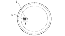
- FIG. 4 is an explanatory view showing the structure of the metal vacuum double container 10, and a hollow portion 2 is formed between the outer container 1 and the inner container 3 of the metal vacuum double container 10.
- FIG. 5 is an explanatory diagram showing the bottom surface of the outer container 1 before the sealing glass 5 flows in the vacuum sealing process.
- FIG. 6 is a schematic cross-sectional view showing a state in the vicinity of the exhaust port 6 before the sealing glass 5 flows in the vacuum sealing process.
- FIG. 7 is a schematic cross-sectional view showing a state in the vicinity of the exhaust port 6 after the sealing glass 5 flows in the vacuum sealing process.
- an exhaust port 6 is formed on the bottom surface of the outer container 1 in order to make the hollow portion 2 of the metal vacuum double container 10 in a vacuum state.
- a recess 4 is formed on the bottom surface of the outer container 1 in order to place the sealing glass 5 in the horizontal direction of the exhaust port 6.
- the metal vacuum double container 10 is arranged so that the exhaust port 6 of the metal vacuum double container 10 in FIG. 1 is downward, that is, the bottom surface shown in FIG.
- the sealing glass 5 is placed in the horizontal direction of the exhaust port 6.
- the metal vacuum double container 10 is put into a vacuum firing furnace with the exhaust port 6 of the metal vacuum double container 10 of FIG. 1 being downward, that is, the bottom surface shown in FIG. It is heated to a temperature below the yield point of the sealing glass 5 in a vacuum state. At that time, the hollow portion 2 is in a vacuum state.
- the metal vacuum double container 10 is heated to a temperature equal to or higher than the yield point of the sealing glass 5 while maintaining the vacuum state of the hollow portion 2, and the sealing glass 5 is foaming in the process. It softens and flows in the horizontal direction, eventually reaches the exhaust port, closes the exhaust port, and enters the state shown in FIG.
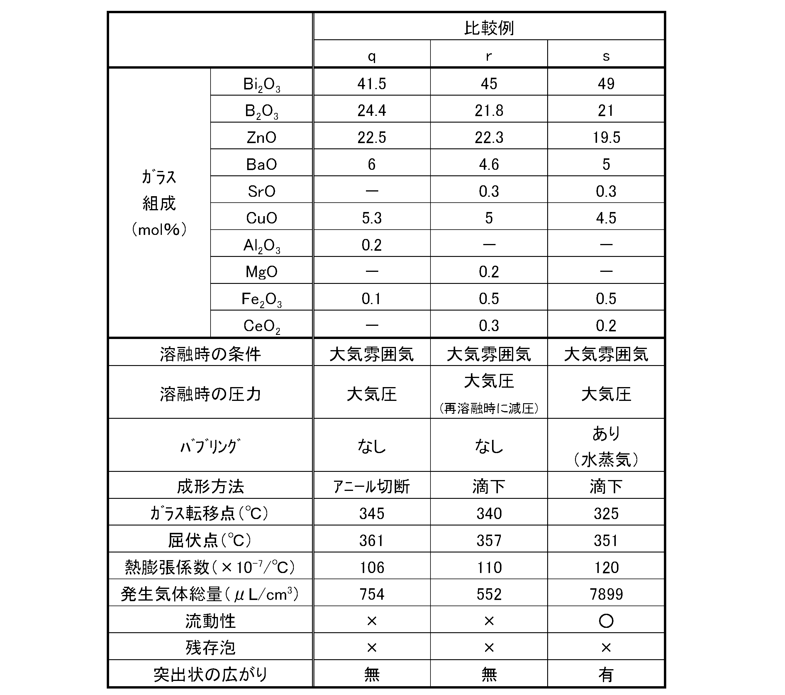
- Tables 1 to 6 show examples of the present invention (sa to l) and comparative examples (samples m to v).
- Samples a to e were prepared as follows.
- a glass batch is prepared using tin monoxide, orthophosphoric acid (85% phosphoric acid), zinc oxide or the like so as to have the glass composition described in the table, and this is put in a zirconium crucible, and the atmosphere in the table And melted at 900 ° C. for 1 hour under the pressure in the table.
- sample e is bubbling N 2 in water, after sufficiently impregnated with water in N 2, was introduced the gas into molten atmosphere.
- the glass batch was completely melted, it was dropped and formed into a cylindrical shape with a mold press immediately after dropping.
- Samples f to i were prepared as follows. A glass batch was prepared using bismuth oxide, boron oxide having a high water content, aluminum hydroxide, etc. so as to have the glass composition described in the table, and this was put into a platinum-rhodium alloy crucible. The mixture was melted at 1000 ° C. for 1 hour under the pressure in the table. Further, the sample i is the O 2 by bubbling in the water, after not sufficiently contain moisture O 2, was bubbled through the gas in the molten glass. In addition, after the glass batch was completely melted, it was dropped and formed into a cylindrical shape with a mold press immediately after dropping.
- Samples j to l were prepared as follows.
- a glass batch is prepared using vanadium pentoxide, orthophosphoric acid (85% phosphoric acid), zinc oxide, boron oxide having a high moisture content, aluminum hydroxide, and the like so as to have the glass composition described in the table. This was put into a platinum-rhodium alloy crucible and melted at 1000 ° C. for 1 hour under the atmosphere and pressure in the table. Sample 1 was bubbled in molten glass after the atmosphere was bubbled in water to sufficiently contain moisture. In addition, after the glass batch was completely melted, it was dropped and formed into a cylindrical shape with a mold press immediately after dropping.
- Sample m was prepared as follows. The prepared glass batch was put into a quartz crucible so as to have the glass composition described in the table, and after the inside of the melting furnace was replaced with Ar, the atmosphere in the table and the pressure in the table were bubbled with dried N 2. It melted at 950 ° C. for 1 hour. Next, the molten glass was molded into a cylindrical shape with a mold press immediately after the drop molding.
- Sample n was produced as follows. So that the glass composition described in Table, placed glass batch was prepared in a quartz crucible, the melting furnace after N 2 substitution, while bubbling with N 2 drying, in the table the atmosphere, in the table It melted at 950 ° C. for 1 hour under pressure. Next, the molten glass was molded into a cylindrical shape with a mold press immediately after the drop molding.
- Sample o was produced as follows. The prepared glass batch was put into a quartz crucible so as to have the glass composition shown in the table, and after the inside of the melting furnace was replaced with nitrogen, the pressure was reduced to 500 Torr, and the temperature in the table was 900 ° C. under the pressure in the table. Melted for 2 hours. Next, the molten glass was poured out into a plate shape, annealed, and then cut into a predetermined volume.
- Sample p was produced as follows. So that the glass composition described in Table, placed glass batch was prepared in a quartz crucible, after the melting furnace and N 2 substitution, by bubbling N 2 in water, excessively moistened with water in the N 2 Then, while bubbling with this gas, it was melted at 950 ° C. for 1 hour under the atmosphere and pressure in the table. Next, the molten glass was molded into a cylindrical shape with a mold press immediately after the drop molding.
- Sample q was prepared as follows. A glass batch is prepared using a glass raw material having a low moisture content so as to have the glass composition described in the table, and the glass batch is placed in a platinum crucible. Melted for hours. Next, the molten glass was poured out into a plate shape, annealed, and then cut into a predetermined volume.
- Samples q and r were produced as follows. A glass batch is prepared using a glass raw material having a low moisture content so as to have the glass composition described in the table, and the glass batch is placed in a platinum crucible. Melted for hours. Next, after pouring the molten glass into a carbon mold, a glass block was obtained. Note that no annealing treatment was performed after molding. Further, the obtained glass block was remelted in a reduced pressure environment, and then dropped.
- Sample s was prepared as follows. Using a glass raw material with a high water content so as to have the glass composition described in the table, a glass batch is prepared, put into a platinum crucible, O 2 is bubbled in water, and O 2 is sufficient. After excessively containing moisture, it was melted at 1000 ° C. for 2 hours under the atmosphere and pressure in the table while bubbling with this gas. Next, the molten glass was poured out into a plate shape, annealed, and then cut into a predetermined volume.
- Samples t and u were produced as follows. A glass batch prepared with a glass raw material having a low water content so as to have the glass composition described in the table was placed in an alumina crucible and melted at 950 ° C. for 1 hour under the atmosphere and pressure in the table. Next, the molten glass was molded into a cylindrical shape with a mold press immediately after the drop molding.
- Sample v was prepared as follows. Using a glass raw material with a high moisture content so as to have the glass composition described in the table, a glass batch is prepared, placed in a platinum crucible, and the atmosphere is bubbled in water to provide sufficient moisture to the atmosphere. After containing excessively, it was melted at 950 ° C. for 2 hours under the atmosphere and pressure in the table while bubbling with this gas. Next, the molten glass was molded into a cylindrical shape with a mold press immediately after the drop molding.
- the glass transition point, the yield point, the thermal expansion coefficient, the total amount of gas generated, the fluidity, the residual bubbles, and the spread on the protrusions were evaluated.
- the glass transition point, yield point, and thermal expansion coefficient are values measured with a push rod type thermal dilatometer (Rigaku Steel TMA).
- the dimension of the measurement sample was 20 ⁇ 5 mm ⁇ .
- the thermal expansion coefficient is a value measured in the temperature range of 30 to 250 ° C.
- the total amount of generated gas was evaluated as follows. Each sample was crushed so as not to be powdered to form a piece having a volume of 35 mm 3 and used as a measurement sample. After putting the measurement sample into the measurement device, the atmosphere in the measurement device was evacuated with an oil rotary pump (rotary pump), then switched to a temperature programmed desorption analysis circuit, and evacuated with a turbo molecular pump. The evacuation was continued until the pressure in the system was stabilized from 1.0 ⁇ 10 ⁇ 5 Pa to 3.0 ⁇ 10 ⁇ 5 Pa. When the pressure in this range was reached, the operating condition of the pump was maintained, and the measurement sample was heated from room temperature to 700 ° C. at 15 ° C. per minute. During heating, the generated gas was introduced into a mass spectrometer, and the total amount of gas was measured. If the mass spectrum obtained by mass spectrometry is analyzed, the total amount of gas can be calculated.
- each sample was formed (molded) into a cylindrical shape having an outer diameter of 5.3 mm ⁇ and a height of 3.0 mm, and this was placed on a SUS304 stainless steel substrate of ⁇ 40 mm ⁇ 0.5 mm thickness and vacuum fired. Baked in a furnace. The firing condition was that the temperature was raised from room temperature to 400 ° C. at 20 ° C./minute, held at 400 ° C. for 20 minutes, then heated from 400 ° C. to 500 ° C. at 20 ° C./minute, and held at 500 ° C. for 20 minutes. Thereafter, the temperature was lowered to room temperature at 20 ° C./min.
- the actual production of the metal vacuum double vessel is generally a batch transfer type (a method of moving between individually temperature controlled vacuum firing furnaces), so the temperature rising rate was set to 20 ° C./min. .
- the vacuum condition is a combination of a rotary pump and a turbo molecular pump. After the pressure is reduced from 1 ⁇ 10 ⁇ 2 Pa to 1 ⁇ 10 ⁇ 3 Pa before the temperature rises, the pump operating condition is maintained until the temperature is lowered to 300 ° C. The condition was Finally, the outer diameter of each sample after firing was measured at four points, and the fluidity was evaluated as “ ⁇ ” if the average value was 9 mm or more, and “x” if it was less than 9 mm.
Landscapes
- Chemical & Material Sciences (AREA)
- Engineering & Computer Science (AREA)
- Materials Engineering (AREA)
- Life Sciences & Earth Sciences (AREA)
- Chemical Kinetics & Catalysis (AREA)
- General Chemical & Material Sciences (AREA)
- Geochemistry & Mineralogy (AREA)
- Organic Chemistry (AREA)
- Food Science & Technology (AREA)
- Thermal Sciences (AREA)
- Physics & Mathematics (AREA)
- Glass Compositions (AREA)
- Thermally Insulated Containers For Foods (AREA)
Abstract
Description


2 中空部
3 内容器
4 凹部(窪み)
5 封止ガラス
6 排気口
10 金属製真空二重容器
Claims (10)
- 金属製真空二重容器に設けられた排気口を真空封止するための封止ガラスにおいて、
真空封止工程で排気口の鉛直上方以外の位置に封止ガラスが載置される構造の金属製真空二重容器に用いられるとともに、
実質的にPb成分を含有せず、
真空状態で30℃から700℃まで15℃/分で昇温した時に発生する気体総量が900~7000μL/cm3であることを特徴とする封止ガラス。 - 真空状態で30℃から700℃まで15℃/分で昇温した時に発生する気体総量が1500~5000μL/cm3であることを特徴とする請求項1に記載の封止ガラス。
- 昇温前に、真空ポンプを用いて1.0×10⁻⁵から3.0×10⁻⁵Paの圧力に減圧した後、真空ポンプの動作条件を維持した上で、700℃まで昇温した時に発生する気体総量が900~7000μL/cm3であることを特徴とする請求項1に記載の封止ガラス。
- 昇温前に、真空ポンプを用いて1.0×10⁻⁵から3.0×10⁻⁵Paの圧力に減圧した後、真空ポンプの動作条件を維持した上で、700℃まで昇温した時に発生する気体総量が1500~5000μL/cm3であることを特徴とする請求項1に記載の封止ガラス。
- 滴下成形法で成形されてなることを特徴とする請求項1~4のいずれかに記載の封止ガラス。
- 溶融ガラスを成形型に流し出すことで作製されてなることを特徴とする請求項1~4のいずれかに記載の封止ガラス。
- ガラス組成として、モル%表示で、SnO 30~70%、P2O5 15~40%、ZnO 0~20%、MgO 0~20%、Al2O3 0~10%、SiO2 0~15%、B2O3 0~30%、WO3 0~20%、Li2O+Na2O+K2O+Cs2O 0~20%含有することを特徴とする請求項1~6のいずれかに記載の封止ガラス。
- ガラス組成として、モル%表示で、Bi2O3 20~55%、B2O3 10~40%、ZnO 0~30%、BaO+SrO 0~15%、CuO 0~20%、Al2O3 0~10%含有することを特徴とする請求項1~6のいずれかに記載の封止ガラス。
- ガラス組成として、モル%表示で、V2O5 20~60%、P2O5 10~40%、Bi2O3 0~30%、TeO2 0~40%、Sb2O3 0~25%、Li2O+Na2O+K2O+Cs2O 0~20%、MgO+CaO+SrO+BaO 0~30%含有することを特徴とする請求項1~6のいずれかに記載の封止ガラス。
- 金属製真空二重容器に設けられた排気口を真空封止する金属製真空二重容器の封止方法において、
実質的にPb成分を含有しない封止ガラスを用いるとともに、
封止ガラスを排気口の鉛直上方以外の位置に載置した後、
真空封止工程で、封止ガラスから気体を発生させつつ、封止ガラスを排気口に到達させて、排気口を真空封止することを特徴とする金属製真空二重容器の封止方法。
Priority Applications (5)
| Application Number | Priority Date | Filing Date | Title |
|---|---|---|---|
| EP09804805A EP2308806A4 (en) | 2008-08-06 | 2009-06-02 | A sealing |
| CN200980119282.4A CN102046549B (zh) | 2008-08-06 | 2009-06-02 | 密封玻璃 |
| US13/054,987 US20110126976A1 (en) | 2008-08-06 | 2009-06-02 | Sealing glass |
| KR1020107023442A KR101520316B1 (ko) | 2008-08-06 | 2009-06-02 | 밀봉 유리 |
| US13/930,602 US20130305786A1 (en) | 2008-08-06 | 2013-06-28 | Sealing glass |
Applications Claiming Priority (2)
| Application Number | Priority Date | Filing Date | Title |
|---|---|---|---|
| JP2008-202978 | 2008-08-06 | ||
| JP2008202978 | 2008-08-06 |
Related Child Applications (1)
| Application Number | Title | Priority Date | Filing Date |
|---|---|---|---|
| US13/930,602 Division US20130305786A1 (en) | 2008-08-06 | 2013-06-28 | Sealing glass |
Publications (1)
| Publication Number | Publication Date |
|---|---|
| WO2010016318A1 true WO2010016318A1 (ja) | 2010-02-11 |
Family
ID=41663543
Family Applications (1)
| Application Number | Title | Priority Date | Filing Date |
|---|---|---|---|
| PCT/JP2009/060080 WO2010016318A1 (ja) | 2008-08-06 | 2009-06-02 | 封止ガラス |
Country Status (6)
| Country | Link |
|---|---|
| US (2) | US20110126976A1 (ja) |
| EP (1) | EP2308806A4 (ja) |
| JP (1) | JP5384203B2 (ja) |
| KR (1) | KR101520316B1 (ja) |
| CN (1) | CN102046549B (ja) |
| WO (1) | WO2010016318A1 (ja) |
Cited By (6)
| Publication number | Priority date | Publication date | Assignee | Title |
|---|---|---|---|---|
| JP2011173735A (ja) * | 2010-02-23 | 2011-09-08 | Nippon Electric Glass Co Ltd | ビスマス系ガラス |
| US8022000B2 (en) * | 2006-01-06 | 2011-09-20 | Hitachi Displays Ltd. | Display device and production method thereof |
| JP2013199410A (ja) * | 2012-03-26 | 2013-10-03 | Asahi Glass Co Ltd | 低融点ガラス体及び低融点ガラス体の製造方法 |
| JP2013208615A (ja) * | 2011-08-09 | 2013-10-10 | Panasonic Corp | 気体吸着材およびその製造方法、ならびに真空断熱体 |
| CN104150778A (zh) * | 2014-08-11 | 2014-11-19 | 海南中航特玻材料有限公司 | 一种无铅低熔点封接玻璃 |
| JP2019202921A (ja) * | 2018-05-25 | 2019-11-28 | 日本電気硝子株式会社 | ガラス組成物及び封着材料 |
Families Citing this family (33)
| Publication number | Priority date | Publication date | Assignee | Title |
|---|---|---|---|---|
| JP2011046550A (ja) * | 2009-08-26 | 2011-03-10 | Nippon Electric Glass Co Ltd | 封止ガラスの製造方法および封止ガラス |
| JP5679519B2 (ja) * | 2010-07-28 | 2015-03-04 | 日本電気硝子株式会社 | 封止ガラス |
| US9309146B2 (en) | 2011-02-22 | 2016-04-12 | Guardian Industries Corp. | Vanadium-based frit materials, binders, and/or solvents and methods of making the same |
| US8802203B2 (en) * | 2011-02-22 | 2014-08-12 | Guardian Industries Corp. | Vanadium-based frit materials, and/or methods of making the same |
| US9290408B2 (en) | 2011-02-22 | 2016-03-22 | Guardian Industries Corp. | Vanadium-based frit materials, and/or methods of making the same |
| TWI490180B (zh) * | 2012-06-22 | 2015-07-01 | Hoya Corp | Optical glass and optical element manufacturing method |
| WO2013191270A1 (ja) * | 2012-06-22 | 2013-12-27 | Hoya株式会社 | ガラスおよび光学素子の製造方法 |
| JP5953537B2 (ja) * | 2012-07-08 | 2016-07-20 | 岡本硝子株式会社 | 低軟化点ガラス粉末 |
| KR20150050575A (ko) * | 2012-08-30 | 2015-05-08 | 코닝 인코포레이티드 | 안티몬-비함유 유리, 안티몬-비함유 프릿 및 프릿으로 기밀된 유리 패키지 |
| JP2014156369A (ja) * | 2013-02-15 | 2014-08-28 | Hitachi Ltd | ガラス及びその製造方法 |
| JP2015151280A (ja) * | 2014-02-12 | 2015-08-24 | 日本電気硝子株式会社 | 光学ガラス |
| JP5793165B2 (ja) * | 2013-04-26 | 2015-10-14 | Hoya株式会社 | ガラス、光学ガラス、プレス成形用ガラス素材および光学素子 |
| JP5793164B2 (ja) * | 2013-04-26 | 2015-10-14 | Hoya株式会社 | ガラス、光学ガラス、プレス成形用ガラス素材および光学素子 |
| CN103449724A (zh) * | 2013-08-23 | 2013-12-18 | 青岛光路玻璃器件有限公司 | 无铅低温封接玻璃 |
| JP6148943B2 (ja) * | 2013-09-03 | 2017-06-14 | タイガー魔法瓶株式会社 | ステンレス鋼製真空二重容器の封着用無鉛ガラス |
| US9834465B2 (en) | 2013-09-30 | 2017-12-05 | Hoya Corporation | Optical glass and method for producing the same |
| CN103723924B (zh) * | 2013-11-20 | 2018-11-02 | 江苏凯尚绿色建筑管理有限公司 | 一种用于负压釜法制造真空玻璃的封边材料 |
| US10358379B2 (en) | 2013-12-11 | 2019-07-23 | Hitachi Chemical Company, Ltd. | Heat-insulating member, low-melting glass composition, and sealing material paste |
| US20160068294A1 (en) * | 2014-09-04 | 2016-03-10 | Steel Technology, Llc | Vacuum flask with tin phosphorus oxide sealing glass |
| CN105170967A (zh) * | 2015-10-13 | 2015-12-23 | 河北钢铁股份有限公司邯郸分公司 | 炼钢浇铸过程中防止空气通过水口进入钢水中的方法 |
| JP6610228B2 (ja) * | 2015-12-10 | 2019-11-27 | 日本電気硝子株式会社 | ガラス管成形用スリーブ |
| CN106495492B (zh) * | 2016-11-01 | 2019-06-07 | 福州大学 | 一种含Sn的低温封接玻璃及其制备和使用方法 |
| CN106495491B (zh) * | 2016-11-01 | 2019-05-10 | 福州大学 | 一种含Al2O3的LED低温封接玻璃 |
| JP2018188341A (ja) * | 2017-05-10 | 2018-11-29 | 株式会社日立製作所 | 複層ガラス及びその製造方法 |
| JP6876537B2 (ja) * | 2017-06-19 | 2021-05-26 | 日本山村硝子株式会社 | ステンレス鋼製真空二重容器封着用無鉛ガラス組成物 |
| JP7027719B2 (ja) * | 2017-08-07 | 2022-03-02 | Agc株式会社 | ガラス組成物およびガラス粉末 |
| CN108640519B (zh) * | 2018-05-31 | 2022-01-11 | 北京天力创玻璃科技开发有限公司 | 无铅封接玻璃及其制备方法 |
| CN109052965B (zh) * | 2018-09-07 | 2021-12-24 | 苏州融睿电子科技有限公司 | 一种组合体、混合料、封接玻璃及其制作方法 |
| KR102217221B1 (ko) | 2018-11-09 | 2021-02-18 | 엘지전자 주식회사 | 무연계 저온 소성 글라스 프릿, 페이스트 및 이를 이용한 진공 유리 조립체 |
| JP7172848B2 (ja) * | 2019-05-17 | 2022-11-16 | 日本電気硝子株式会社 | ガラス組成物及び封着材料 |
| GB201915010D0 (en) * | 2019-10-17 | 2019-12-04 | Johnson Matthey Plc | Composition, paste and methods |
| KR102504050B1 (ko) * | 2020-11-11 | 2023-02-28 | 한국광기술원 | 친환경 유리 실링재 및 그의 제조방법 |
| CN112573015A (zh) * | 2020-12-08 | 2021-03-30 | 赣州中瓷科技有限公司 | 一种真空保温容器的无铅玻璃密封组件及其制作方法 |
Citations (10)
| Publication number | Priority date | Publication date | Assignee | Title |
|---|---|---|---|---|
| JPH06141989A (ja) | 1992-11-12 | 1994-05-24 | Nippon Sanso Kk | 金属製真空二重容器の製造方法 |
| JPH07289449A (ja) | 1994-04-28 | 1995-11-07 | Tiger Vacuum Bottle Co Ltd | 金属製真空保温容器の真空封止構造 |
| JPH10165A (ja) * | 1996-06-14 | 1998-01-06 | Tiger Vacuum Bottle Co Ltd | 金属製真空二重瓶 |
| JP2001106548A (ja) * | 1999-10-07 | 2001-04-17 | Nippon Electric Glass Co Ltd | 低融点ガラス及び封着用材料 |
| JP2002348152A (ja) * | 2001-05-29 | 2002-12-04 | Tiger Vacuum Bottle Co Ltd | 金属製真空二重容器とその製造方法、封着用組成物 |
| JP2004067406A (ja) * | 2002-08-02 | 2004-03-04 | Asahi Techno Glass Corp | 金属製真空二重構造容器の封止用フリット及び金属製真空二重構造容器 |
| JP2005319150A (ja) | 2004-05-11 | 2005-11-17 | Nippon Electric Glass Co Ltd | 封止用ガラス |
| JP2005350314A (ja) | 2004-06-11 | 2005-12-22 | Nippon Electric Glass Co Ltd | 封止用ガラスおよび封止方法 |
| JP2006290665A (ja) * | 2005-04-08 | 2006-10-26 | Boe Technology Group Co Ltd | 無鉛シーリングガラス粉末及び製造方法 |
| JP2008024558A (ja) * | 2006-07-24 | 2008-02-07 | Nihon Yamamura Glass Co Ltd | 金属製真空二重容器の封着用無鉛ガラス組成物 |
Family Cites Families (3)
| Publication number | Priority date | Publication date | Assignee | Title |
|---|---|---|---|---|
| US2305739A (en) * | 1939-05-09 | 1942-12-22 | Shackelford Orie | Apparatus and method for charging molds with molten glass |
| US3929494A (en) * | 1972-12-22 | 1975-12-30 | Owens Illinois Inc | Sealant for glass-ceramic surfaces |
| JP2005052208A (ja) * | 2003-08-05 | 2005-03-03 | Nippon Electric Glass Co Ltd | 金属製真空二重容器の封止用ガラス |
-
2009
- 2009-06-02 KR KR1020107023442A patent/KR101520316B1/ko active IP Right Grant
- 2009-06-02 CN CN200980119282.4A patent/CN102046549B/zh not_active Expired - Fee Related
- 2009-06-02 EP EP09804805A patent/EP2308806A4/en not_active Withdrawn
- 2009-06-02 JP JP2009133166A patent/JP5384203B2/ja not_active Expired - Fee Related
- 2009-06-02 US US13/054,987 patent/US20110126976A1/en not_active Abandoned
- 2009-06-02 WO PCT/JP2009/060080 patent/WO2010016318A1/ja active Application Filing
-
2013
- 2013-06-28 US US13/930,602 patent/US20130305786A1/en not_active Abandoned
Patent Citations (10)
| Publication number | Priority date | Publication date | Assignee | Title |
|---|---|---|---|---|
| JPH06141989A (ja) | 1992-11-12 | 1994-05-24 | Nippon Sanso Kk | 金属製真空二重容器の製造方法 |
| JPH07289449A (ja) | 1994-04-28 | 1995-11-07 | Tiger Vacuum Bottle Co Ltd | 金属製真空保温容器の真空封止構造 |
| JPH10165A (ja) * | 1996-06-14 | 1998-01-06 | Tiger Vacuum Bottle Co Ltd | 金属製真空二重瓶 |
| JP2001106548A (ja) * | 1999-10-07 | 2001-04-17 | Nippon Electric Glass Co Ltd | 低融点ガラス及び封着用材料 |
| JP2002348152A (ja) * | 2001-05-29 | 2002-12-04 | Tiger Vacuum Bottle Co Ltd | 金属製真空二重容器とその製造方法、封着用組成物 |
| JP2004067406A (ja) * | 2002-08-02 | 2004-03-04 | Asahi Techno Glass Corp | 金属製真空二重構造容器の封止用フリット及び金属製真空二重構造容器 |
| JP2005319150A (ja) | 2004-05-11 | 2005-11-17 | Nippon Electric Glass Co Ltd | 封止用ガラス |
| JP2005350314A (ja) | 2004-06-11 | 2005-12-22 | Nippon Electric Glass Co Ltd | 封止用ガラスおよび封止方法 |
| JP2006290665A (ja) * | 2005-04-08 | 2006-10-26 | Boe Technology Group Co Ltd | 無鉛シーリングガラス粉末及び製造方法 |
| JP2008024558A (ja) * | 2006-07-24 | 2008-02-07 | Nihon Yamamura Glass Co Ltd | 金属製真空二重容器の封着用無鉛ガラス組成物 |
Non-Patent Citations (1)
| Title |
|---|
| See also references of EP2308806A4 * |
Cited By (8)
| Publication number | Priority date | Publication date | Assignee | Title |
|---|---|---|---|---|
| US8022000B2 (en) * | 2006-01-06 | 2011-09-20 | Hitachi Displays Ltd. | Display device and production method thereof |
| JP2011173735A (ja) * | 2010-02-23 | 2011-09-08 | Nippon Electric Glass Co Ltd | ビスマス系ガラス |
| JP2013208615A (ja) * | 2011-08-09 | 2013-10-10 | Panasonic Corp | 気体吸着材およびその製造方法、ならびに真空断熱体 |
| JP2013199410A (ja) * | 2012-03-26 | 2013-10-03 | Asahi Glass Co Ltd | 低融点ガラス体及び低融点ガラス体の製造方法 |
| CN104150778A (zh) * | 2014-08-11 | 2014-11-19 | 海南中航特玻材料有限公司 | 一种无铅低熔点封接玻璃 |
| JP2019202921A (ja) * | 2018-05-25 | 2019-11-28 | 日本電気硝子株式会社 | ガラス組成物及び封着材料 |
| WO2019225335A1 (ja) * | 2018-05-25 | 2019-11-28 | 日本電気硝子株式会社 | ガラス組成物及び封着材料 |
| JP7222182B2 (ja) | 2018-05-25 | 2023-02-15 | 日本電気硝子株式会社 | ガラス組成物及び封着材料 |
Also Published As
| Publication number | Publication date |
|---|---|
| EP2308806A4 (en) | 2013-01-02 |
| EP2308806A1 (en) | 2011-04-13 |
| KR20110049743A (ko) | 2011-05-12 |
| JP2010057893A (ja) | 2010-03-18 |
| JP5384203B2 (ja) | 2014-01-08 |
| CN102046549B (zh) | 2014-05-28 |
| US20110126976A1 (en) | 2011-06-02 |
| US20130305786A1 (en) | 2013-11-21 |
| CN102046549A (zh) | 2011-05-04 |
| KR101520316B1 (ko) | 2015-05-14 |
Similar Documents
| Publication | Publication Date | Title |
|---|---|---|
| JP5384203B2 (ja) | 封止ガラス | |
| JP5354445B2 (ja) | 金属被覆用ガラス及び半導体封止材料 | |
| JP2008037740A (ja) | 封着用ガラス組成物および封着材料 | |
| WO2008007504A1 (fr) | Composition de verre pour l'étanchéité et matériau étanche | |
| JP5170817B2 (ja) | ガラスの溶融方法 | |
| JP6617541B2 (ja) | 無鉛ガラス及び封着材料 | |
| CN106977117A (zh) | 复层玻璃及其制造方法 | |
| JP4596358B2 (ja) | 封止用ガラス | |
| JP4529173B2 (ja) | 封止用ガラスおよび封止方法 | |
| JP2011046550A (ja) | 封止ガラスの製造方法および封止ガラス | |
| JP4093353B2 (ja) | 金属製真空二重構造容器の封止用フリット及び金属製真空二重構造容器 | |
| JP2010100485A (ja) | 液滴成形用ノズル | |
| JP2003238199A (ja) | プレスフリット | |
| JP2005132650A (ja) | 封着用複合材料 | |
| JP5071876B2 (ja) | 光透過用金属キャップ | |
| JP4556544B2 (ja) | 封止用ガラス | |
| CN110395905B (zh) | 用于制作玻璃的组合物、封接料及制备方法、玻璃及制造方法 | |
| WO2012014619A1 (ja) | 封止用ガラス及び封止用複合材料 | |
| JP6489414B2 (ja) | ガラスの製造方法 | |
| JP2019147720A (ja) | 断熱部材用ゲッター材、及びそれを用いた断熱部材 | |
| JP5669027B2 (ja) | 封着用ガラス組成物および封着材料 | |
| JP5679519B2 (ja) | 封止ガラス | |
| JP2022063400A (ja) | 封止材料 | |
| JP2016108164A (ja) | 封着用ガラス及び封着材料 | |
| JP2001048580A (ja) | Crt用フリット |
Legal Events
| Date | Code | Title | Description |
|---|---|---|---|
| WWE | Wipo information: entry into national phase |
Ref document number: 200980119282.4 Country of ref document: CN |
|
| 121 | Ep: the epo has been informed by wipo that ep was designated in this application |
Ref document number: 09804805 Country of ref document: EP Kind code of ref document: A1 |
|
| ENP | Entry into the national phase |
Ref document number: 20107023442 Country of ref document: KR Kind code of ref document: A |
|
| WWE | Wipo information: entry into national phase |
Ref document number: 13054987 Country of ref document: US |
|
| WWE | Wipo information: entry into national phase |
Ref document number: 2009804805 Country of ref document: EP |
|
| NENP | Non-entry into the national phase |
Ref country code: DE |