WO2010001663A1 - 光ファイバケーブル及び光ファイバテープ - Google Patents
光ファイバケーブル及び光ファイバテープ Download PDFInfo
- Publication number
- WO2010001663A1 WO2010001663A1 PCT/JP2009/059146 JP2009059146W WO2010001663A1 WO 2010001663 A1 WO2010001663 A1 WO 2010001663A1 JP 2009059146 W JP2009059146 W JP 2009059146W WO 2010001663 A1 WO2010001663 A1 WO 2010001663A1
- Authority
- WO
- WIPO (PCT)
- Prior art keywords
- optical fiber
- core
- cable
- core coated
- resin
- Prior art date
Links
Images


Classifications
-
- G—PHYSICS
- G02—OPTICS
- G02B—OPTICAL ELEMENTS, SYSTEMS OR APPARATUS
- G02B6/00—Light guides; Structural details of arrangements comprising light guides and other optical elements, e.g. couplings
- G02B6/44—Mechanical structures for providing tensile strength and external protection for fibres, e.g. optical transmission cables
- G02B6/4401—Optical cables
- G02B6/441—Optical cables built up from sub-bundles
-
- G—PHYSICS
- G02—OPTICS
- G02B—OPTICAL ELEMENTS, SYSTEMS OR APPARATUS
- G02B6/00—Light guides; Structural details of arrangements comprising light guides and other optical elements, e.g. couplings
- G02B6/44—Mechanical structures for providing tensile strength and external protection for fibres, e.g. optical transmission cables
- G02B6/4401—Optical cables
- G02B6/4403—Optical cables with ribbon structure
-
- G—PHYSICS
- G02—OPTICS
- G02B—OPTICAL ELEMENTS, SYSTEMS OR APPARATUS
- G02B6/00—Light guides; Structural details of arrangements comprising light guides and other optical elements, e.g. couplings
- G02B6/44—Mechanical structures for providing tensile strength and external protection for fibres, e.g. optical transmission cables
- G02B6/4401—Optical cables
- G02B6/4429—Means specially adapted for strengthening or protecting the cables
- G02B6/443—Protective covering
- G02B6/4432—Protective covering with fibre reinforcements
- G02B6/4433—Double reinforcement laying in straight line with optical transmission element
Definitions
- the present invention relates to an optical fiber tape and an optical fiber cable, which are components of information wiring using optical fibers outdoors and indoors.
- an optical fiber cable having a small diameter and a high density for example, in Patent Document 1, a plurality of optical fibers in which an increase in optical loss due to bending is reduced and a plurality of single-core coated optical fibers in which the outer periphery of the optical fiber is coated are assembled.
- a multi-fiber optical fiber cable having a very small diameter and high density has been proposed by using a structure in which the outer periphery of the bundle is coated.
- the optical fiber cable described in Patent Document 1 uses a single-core coated optical fiber, it is necessary to connect the optical fiber cables when constructing an optical fiber transmission line, but the number of connections increases. There was a problem of poor connection efficiency.
- optical fiber tape cores coated with a plurality of single-core coated optical fibers arranged in parallel are optical fiber units that can be connected together with a fusion splicer, etc., and are often used for conventional optical fiber cables. It has been.
- the conventional optical fiber ribbon has a bending anisotropy that it is difficult to bend in the width direction due to its shape, and when subjected to the bending in the width direction in the optical fiber cable, the optical fiber has a large strain or light. Since loss occurs, it is necessary to use an optical fiber tape or a cable structure that can suppress this.
- Each of the optical fiber cables described in Patent Documents 2 to 5 uses an optical fiber tape core wire in which a plurality of single-core coated optical fibers are intermittently bonded in the longitudinal direction. Improvement of single-fiber separation performance for separating only a desired optical fiber from the optical fiber ribbon at the time of post-branching is attempted.
- Each of the optical fiber cables of Patent Documents 2 and 3 is an optical fiber tape core in which resin portions for adhering the entire width direction of a plurality of single-core coated optical fibers arranged in parallel are intermittently arranged in the longitudinal direction. And is housed in the cable in a stacked state.
- the optical fiber cable of Patent Document 4 is an optical fiber tape core in which a conventional optical fiber ribbon is intermittently divided in the manufacturing process, and the divided portion is shifted in the width direction along the longitudinal direction of the optical fiber tape. It uses wires and is housed in the cable in a stacked state. In addition, it is possible to reduce the distortion of the optical fiber against the bending in the width direction that the optical fiber tape core wire undergoes during manufacture by arranging the dividing portion in, for example, the twist reversal portion of the SZ twisted slot type optical fiber cable. Has been.
- the resin part is a resin in which only two adjacent cores of the single-core coated optical fiber are bonded to each other, and the length of the resin part is shorter than the length of the unbonded part and is adjacent in the width direction.
- the part uses an optical fiber tape core wire characterized in that it is spaced apart, and some are folded and accommodated in a cable. Since such an optical fiber ribbon has a small bending anisotropy and can be easily folded into a cylindrical shape, it may be possible to manufacture a small-diameter and high-density optical fiber cable in the same manner as a bundle of single-core coated optical fibers. Are known.
- an optical fiber cable is laid on a bent pipe or the like and used for a long time, it can maintain a stable optical loss characteristic against an external force applied to the cable, Even in the radius, it is necessary to ensure sufficient long-term reliability so that a large strain is not applied to the optical fiber.
- the optical fiber cables described in Patent Documents 2 to 4 are accommodated in the cable core part in a form in which a plurality of optical fiber tape core wires bonded intermittently are stacked.
- a plurality of optical fiber ribbons are housed in a stacked state, a large gap is formed in the cable. Therefore, in order to increase the mounting density of the cable core, it is overwhelming to use a bundle of single-core coated optical fibers. Is advantageous. For this reason, the optical fiber cables described in Patent Documents 2 to 4 are unsuitable for small diameter and high density optical fiber cables.
- the optical fiber cables described in Patent Documents 2 to 4 are bonded to the whole or three or more of the optical fiber ribbons in the width direction.
- the resin portion is present, and the resin portion has a large bending anisotropy, which is insufficient because a large optical loss or distortion occurs locally during cable manufacturing or cable bending.
- the optical fiber cable shown at the end of the background art has been devised to reduce the bending anisotropy of the optical fiber ribbon described above, and can be accommodated at the same mounting density as when a bundle of single-core coated optical fibers is used. Therefore, the mounting density of the cable core part can be increased as much as possible.
- optical loss increases due to random bending applied to the optical fiber during manufacturing of the optical fiber cable, and optical loss increases due to bending of the optical fiber in the cable due to bending applied to the cable and side pressure. Occurs, and stable light loss characteristics cannot be maintained.
- the strain applied when the cable is bent has a problem in that long-term reliability cannot be secured because strain exceeding the allowable value is applied to the optical fiber depending on the bonding state of the single-core coated optical fiber in the optical fiber ribbon used for the cable. is there.
- the present invention has been made in view of the above circumstances, and has a good optical fiber connection efficiency, prevents an increase in optical loss generated in the optical fiber, provides a stable optical loss characteristic, and reduces distortion applied to the optical fiber.
- the first object is to provide a small-diameter and high-density optical fiber cable with sufficient long-term reliability.
- Each of the optical fiber tapes used in the optical fiber cables described in Patent Documents 2 to 4 and 6 has a structure in which the optical fiber tapes are intermittently bonded and is manufactured continuously in the length direction. Compared to a tape, a mechanism for intermittently applying or dividing a resin is required for a manufacturing apparatus, and there is a problem that the manufacturing speed is not excellent and, as a result, economical efficiency is lacking.
- the present invention has been made in view of the above circumstances, and has a thickness and length that can easily buckle a connecting portion that connects adjacent single-core coated optical fibers against an external force applied in the width direction of the optical fiber tape. Therefore, the bending anisotropy of the optical fiber tape can be reduced, and the optical fiber tape with sufficient long-term reliability and the small diameter and high density can be secured without causing excessive distortion during bending.
- a second object is to provide an optical fiber cable that can be used.
- the present invention is an optical fiber cable comprising an optical fiber ribbon comprising three or more single-core coated optical fibers coated on the outer periphery of an optical fiber,
- the optical fiber has a bending loss characteristic in which an increase in optical loss when bent at a radius of 13 mm at a wavelength of 1.55 ⁇ m is 0.2 dB / 10 turn or less, and the optical fiber ribbon is formed by two adjacent optical fibers.
- the length is shorter than the length of the non-resin portion where the same adjacent two-core single-core coated optical fibers are not bonded, and the resin portions adjacent in the width direction of the optical fiber ribbon are the optical fibers.
- the optical fiber cable accommodates a unit in which a plurality of units each composed of a plurality of single-core coated optical fibers constituting the optical fiber ribbon are twisted together.
- the outer periphery of the cable core portion and the outer periphery of the cable core portion has a jacket, and the ratio of the cross-sectional area occupied by the plurality of single-core coated optical fibers to the cross-sectional area of the cable core portion is 0.3 or more. It is a feature.
- the present invention is configured so that n (n is a plurality) single-core coated optical fibers arranged so as not to contact each other, and adjacent single-core coated optical fibers are arranged in the longitudinal direction.
- An optical fiber tape composed of n-1 connecting portions connected continuously to each other, wherein at least n / 2-1 connecting portions, the thickness of the connecting portion is b, When the outer diameter is d, b ⁇ d, and the length h of the connecting portion is in the range of 100 (b / d) ⁇ 2 ⁇ h ⁇ 312.5-d (the unit is ⁇ m). It is a feature.
- a resin having a Young's modulus after curing of less than 500 MPa is used as a material for at least n / 2-1 connecting portions of the plurality of connecting portions. It is a feature.
- the present invention is characterized in that in the optical fiber tape, a layer of the same material as that of the connecting portion is formed around the single-core coated optical fiber.
- the present invention is characterized in that, in the optical fiber tape, the connecting portion is arranged shifted in the thickness direction of the optical fiber tape from a line connecting the centers of the single-core coated optical fibers.
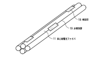
- the present invention is characterized in that in the optical fiber tape, a photonic crystal fiber having a hole in a cladding portion of the optical fiber is used as the optical fiber.
- the optical fiber cable of the present invention is characterized in that a plurality of the optical fiber tapes are collected and accommodated.
- the optical fiber cable of the present invention comprises a cable core portion that accommodates a plurality of twisted units of the optical fiber tape, and a jacket applied to the outer periphery of the cable core portion,
- the ratio of the cross-sectional area occupied by the plurality of single-core coated optical fibers to the cross-sectional area of the cable core portion is 0.3 or more.
- two strength members are embedded in the jacket so as to be symmetrical with respect to the center of the optical fiber cable, and the strength members are embedded.
- the thickness of the outer cover of the part which is present is characterized by being thicker than the thickness of the other outer cover.
- the optical fiber cable of the present invention maintains a stable optical loss characteristic with respect to external force applied during use at a mounting density of the cable core portion that is almost equivalent to that of an optical fiber cable using a single-core coated optical fiber,
- the distortion applied to the optical fiber with respect to cable bending is small, and sufficient long-term reliability can be ensured.
- the optical fiber cable of the present invention can be collectively connected using the optical fiber ribbon, there is an effect that the connection efficiency is high.
- the desired optical fiber can be easily distinguished and taken out, and the single-core separation at the time of intermediate post-branching is also excellent.
- the connecting portion for connecting adjacent single-core coated optical fibers has a thickness and length that easily buckles against an external force applied in the width direction of the optical fiber tape. Because it easily buckles against external force applied in the width direction of the fiber tape, the bending anisotropy of the optical fiber tape can be made very small, and excessive strain does not occur even when the cable is bent. Reliability can be ensured, multi-core batch connection is possible, manufacturing speed is high, and economy is excellent.
- FIG. 6 is a characteristic diagram showing measurement results obtained by performing a temperature cycle test on the optical fiber cable according to the embodiment of the present invention in a temperature range of ⁇ 30 ° C. to 70 ° C.
- FIG. 1 It is a characteristic view which shows the example of a result of having measured distribution of the distortion added to the optical fiber longitudinal direction when the optical fiber cable which concerns on embodiment of this invention is bent. It is a characteristic view which shows the example of a result of having measured distribution of the distortion added to the optical fiber longitudinal direction when the optical fiber cable which concerns on embodiment of this invention is bent. It is a characteristic view which shows the measurement result of the strain distribution added to the optical fiber longitudinal direction in a cable, when the tape core optical fiber cable which concerns on the comparative example of this invention is bent.
- FIG. 6 is a characteristic diagram showing a measurement result of a relationship between a maximum strain value applied in the longitudinal direction of the optical fiber in the cable and a bending radius of the cable when the optical fiber cable, the single-core fiber and the ribbon fiber-optic cable according to the embodiment of the present invention are bent. is there.
- (A) is sectional drawing which shows an example of the optical fiber tape which concerns on the 1st Embodiment of this invention
- (b) is a cross section which shows the other example of the optical fiber tape which concerns on the 1st Embodiment of this invention
- the single-core coated optical fibers 11 arranged in parallel as shown in FIG. 2 are connected by the resin portion 18 as an optical fiber ribbon, and the single-core coated optical fiber (11 as shown in FIG. 8). ⁇ 14, 21 ⁇ 28) connected by connecting portions (15 ⁇ 17, 31 ⁇ 37) are referred to as optical fiber tapes.
- FIG. 1 is a cross-sectional view showing an optical fiber cable according to an embodiment of the present invention.
- 11 is a single-core coated optical fiber
- 92 is an identification thread
- 93 is a protective tape
- 94 is a jacket
- 95 is a tensile body
- 96 is a projection
- 97 is a tear string.
- a unit is formed by winding an identification yarn 92 around the outer periphery of an optical fiber bundle in which a plurality of, for example, 20 single-core coated optical fibers 11 having a diameter of 0.25 mm are densely assembled. Furthermore, the unit has a presser winding layer composed of a plurality of thin protective tapes 93 on the outer periphery in which a plurality of units, for example, ten units are twisted in one direction, and are densely assembled. 94, a very high-density, 200-fiber optical fiber cable is constructed. The unit is configured by using an optical fiber tape core composed of three or more single-core coated optical fibers in which the outer periphery of the optical fiber is coated. That is, the multi-core optical fiber cable is configured to include a cable core portion that accommodates a plurality of twisted units, and a jacket on the outer periphery of the cable core portion.
- the jacket 94 is made of, for example, polyethylene.
- the optical fiber cable of FIG. 1 has protrusions 96 embedded in the jacket 94 so that the two strength members 95 are symmetrical with respect to the center of the optical fiber cable.
- the thickness of the outer cover 94 of the protruding portion 96 is thicker than the thickness of the outer cover 94 other than the protruding portion 96.
- the strength member 95 is made of, for example, a steel wire having a diameter of 0.95 mm.
- a tear string 97 is provided at a position symmetrical to each other with respect to the center of the optical fiber cable at an intermediate portion between the strength members 95 in the jacket 94. The tear string 97 is provided for tearing the jacket 94 and taking out the single-core coated optical fiber 11.
- ⁇ is the circular ratio. Therefore, the cross-sectional area Afiber occupied by a plurality of single-core coated optical fibers 11 in this embodiment is 9.82 mm 2 .
- the ratio of the cross-sectional area Afiber occupied by a plurality of single-core coated optical fibers 11 to the cross-sectional area Acore of the cable core portion is Afiber / Acore ⁇ 0.36.
- Afiber / Acore was about 0.3 to about 0.55 in a 100-1000 optical fiber cable. Therefore, this embodiment is characterized in that the ratio of the cross-sectional area occupied by the plurality of single-core coated optical fibers to the cross-sectional area of the cable core portion is 0.3 or more.
- the same In the 200-core optical fiber cable Afiber / Acore is about 0.1, and the optical fiber cable according to the embodiment of the present invention is three times or more, which is greatly different from the conventional optical fiber cable, and has a very high density. It can be seen that
- the cross-sectional shape of the optical fiber cable according to the embodiment of the present invention is not necessarily provided with the protrusion 96 in the outer sheath 94, and may be circular. Further, the number n of the optical fibers 11 in the optical fiber cable is usually about several tens to 1,000. Further, the standard outer diameter d of the single-core coated optical fiber 11 is not limited to 0.25 mm, and may be other outer diameters such as 0.5 mm and 0.9 mm that are currently used.
- ten units are twisted in one direction.
- the present invention is not limited to this, and for example, SZ twisting having a twisted portion in the opposite direction may be performed in the middle.
- the outer diameter of the optical fiber cable (or the shorter diameter when the cross-sectional shape is not circular) is D, and the optical fiber cable is bent at a bending radius of 10D.
- the maximum strain applied in the direction is 0.2% or less.
- FIG. 2 is a schematic perspective view showing an optical fiber ribbon according to an embodiment of the present invention
- FIG. 3 is a schematic perspective view showing a folded state of the optical fiber ribbon according to an embodiment of the present invention.
- 18 is a resin part
- 19 is a non-resin part.
- the optical fiber tape constituting the optical fiber cable has three or more, for example, four single-core coated optical fibers 11 and two adjacent single-core coated optical fibers 11.
- a plurality of resin portions 18 to be bonded are provided, and the resin portions 18 are two-dimensionally arranged in a longitudinal direction and a width direction.
- the resin portion 18 may be made of an ultraviolet curable resin, a thermoplastic resin, or a thermosetting resin that bonds the single-core coated optical fibers 11 together. Moreover, in order to provide the discriminability of the optical fiber ribbon, the resin portion 18 may be colored. An explanation will be given of a case where N single-core coated optical fibers 11 (N is a multiple of 8) are arranged in parallel. It is assumed that the single-core coated optical fibers 11 are grouped every eight. The resin portion 18 is colored in a different color for each group. For example, the resin portion 18 that connects the first group of single-core coated optical fibers 11 is red, the resin portion 18 that connects the second group of single-core coated optical fibers 11 is yellow, and the third group of single-core coated optical fibers 11.
- the resin portion 18 that connects the two is color-coded such as blue.
- each group employs resin portions 18 of different colors.
- the color of the resin part 18 that connects the single-core coated optical fibers 11 between the groups can be improved, for example, by setting the color to black. Note that only the color of the resin portion 18 that connects the single-core coated optical fibers 11 between the groups may be different from the color of the resin portion 18 that connects the single-core coated optical fibers 11 in the group.
- the optical fiber ribbon can have an identification function for identifying a group. Further, the operator can easily know the number of single-core coated optical fibers arranged in parallel with the optical fiber ribbon using this identification function.
- the optical fiber tape core shown in FIG. 2 has the length B of the resin portion 18 provided between the same adjacent two-core single-coated optical fibers 11 and the same two adjacent single-core fibers. It is characterized by being shorter than the length AB of the non-resin portion 19 where the coated optical fiber 11 is not bonded.
- the interval A between the resin portions 18 arranged in the longitudinal direction of the single-core coated optical fiber 11 is about 200 mm
- the length B of the resin portion is about 80 mm. That is, in this embodiment, the ratio of the length of the resin part 18 to the interval between the resin parts 18 arranged in the longitudinal direction of the single-core coated optical fiber 11 is 0.4 or less, and the length of the resin part 18 Is 80 mm or less.
- a material having a Young's modulus smaller than that used for the outermost coating layer of the single-core coated optical fiber 11 is used as the material of the resin portion 18.
- the resin portions 18 adjacent in the width direction of the optical fiber ribbon are disposed apart from each other in the longitudinal direction of the optical fiber ribbon.
- the resin portion 18 is arranged so as to have a portion where the resin portion 18 does not exist at all in the width direction of the optical fiber ribbon. This is because the adjacent resin portions 18 do not affect each other so that the optical fiber tape core wire can be easily folded as shown in FIG. This is because it is easy to increase the ratio of the occupied area, that is, Afiber / Acore.
- the length C of the portion where the resin portion 18 does not exist at all in the width direction of the optical fiber ribbon is desirably 50 mm or less.
- the resin portion 18 Since it is unknown where to cut when using the optical fiber cable, a state where the resin portion 18 does not exist at all in the width direction of the optical fiber ribbon is disposed at the tip of the optical fiber ribbon However, it can be said that it is a situation in which it is difficult to align the plurality of single-core coated optical fibers 11 in a plane when connecting the optical fiber ribbons. For this reason, from the viewpoint of ensuring a certain connection efficiency, the resin portion 18 is completely present in the width direction of the optical fiber ribbon from the length (about 50 mm) of the optical fiber holder used for general optical fiber fusion splicing. It is necessary to make the length of the portion not to be short and at least one resin portion 18 to exist.
- optical fiber tape core wire composed of the four-core single-core coated optical fiber 11 and the resin portion 18 that bonds the single-core coated optical fibers 11 to each other has been described.
- the optical fiber ribbon may be composed of another number of cores, for example, an eight-core single-core coated optical fiber and a resin portion.
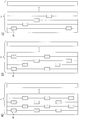
- FIG. 17 is a diagram for explaining an arrangement pattern of resin portions in the optical fiber ribbon in the present embodiment.
- FIG. 17A shows a resin portion 18 that bonds two adjacent single-core coated optical fibers 11, for example, the n-th single-core coated optical fiber 11 and the (n + 1) -th single-core coated optical fiber 11,
- FIG. 17A shows a resin portion 18 that bonds two adjacent single-core coated optical fibers 11, for example, the n-th single-core coated optical fiber 11 and the (n + 1) -th single-core coated optical fiber 11,
- FIG. 17B there is a resin portion 18 for bonding the n-th single-core coated optical fiber 11 and the (n + 1) -th single-core coated optical fiber 11, and in the width direction of the optical fiber ribbon of the resin portion 18.
- the other resin portion 18 is arranged between the n + 4th single-core coated optical fiber 11 and the n + 5th single-core coated optical fiber 11 with an arrangement interval between the resin portion 18 and the other resin portion 18. It may be sufficient, and arrangement intervals may be further provided.
- FIG. 17 (c) shows an optical fiber ribbon that has only one resin portion 18 in the width direction of the optical fiber ribbon.
- the optical fiber cable of the present embodiment may include any one of the optical fiber ribbons shown in FIGS. 17 (a) to 17 (c).
- the length and the arrangement interval of the resin portions arranged between the first and second fibers of the four-core single-core coated optical fibers arranged in parallel are, for example, resins arranged between the second and third fibers. It may be different from the length of the part and the arrangement interval. In this case, it is necessary to set the arrangement interval so that the resin portions are not adjacent to each other in the width direction of the optical fiber ribbon.
- FIG. 14 is a view for explaining optical fiber ribbons having two types of arrangement intervals of the resin portions 18. It is assumed that the single-core coated optical fibers 11 are grouped every eight. The optical fiber ribbon of FIG. 14 uses two types of arrangement intervals.
- the arrangement interval A ′ of the resin portions 18 ′ arranged between the 8n (n is a natural number) and the 8n + 1-th single-core coated optical fibers 11, that is, the resin portions 18 ′ arranged between the groups is This is different from the arrangement interval A of the resin portions 18 in the group G.
- the optical fiber ribbon can have an identification function for identifying the group G. For example, since a multi-fiber optical fiber ribbon composed of N pieces can easily identify a group G (subunit tape) of an arbitrary unit, by separating the resin portion 18 ′ as a starting point, the group G ( Subunit tape) can be easily operated and connected in units of the number of core wires.
- a photonic crystal fiber having a hole in the clad portion of the optical fiber can be used as the optical fiber.
- FIG. 4 is a characteristic diagram showing the results of measuring the relationship between the increase in optical loss at the time of manufacturing the optical fiber cable according to the embodiment of the present invention and the bending loss characteristic of the optical fiber used.
- the bending loss characteristic of the optical fiber is represented by a minimum allowable bending radius (a bending radius that becomes 0.2 dB / 10 turn at a wavelength of 1.55 ⁇ m), and is experimentally obtained from a bending test of the optical fiber.
- Several types of optical fibers having various minimum allowable bending radii were mounted on the optical fiber cable according to the present embodiment.
- the bending loss characteristic in this embodiment is “IEC 60793-1-47 edition 2 (2006-09)“ Optical fibers ”. -Part1-47 Measurement methods and test procedure-Obtained by the measurement method specified in "Macrobending loss”.
- FIG. 4 shows that when the minimum allowable bending radius of the optical fiber is increased, that is, when the loss tolerance to the bending of the optical fiber is reduced, the optical loss is rapidly increased during manufacturing. This is due to random bending applied to the optical fiber when the optical fiber cable is manufactured. Further, it can be seen that by using an optical fiber having a minimum allowable bending radius of about 13 mm or less, an increase in optical loss at the time of manufacturing the optical fiber cable according to the present embodiment can be suppressed, and other optical fibers cannot be suppressed.
- FIG. 5 is a characteristic diagram showing measurement results obtained by performing a temperature cycle test in the temperature range of ⁇ 30 ° C. to 70 ° C. for the optical fiber cable according to the embodiment of the present invention.
- the optical loss increases rapidly. This is because bending and lateral pressure are applied to the optical fiber in the cable because the cable expands and contracts as the temperature changes.
- an optical fiber having a minimum allowable bending radius of about 13 mm or less stable optical loss characteristics can be maintained, and other optical fibers cannot be maintained.
- an optical fiber having a minimum allowable bending radius of 13 mm or less may be used as a condition for suppressing an increase in optical loss due to temperature change when manufacturing the optical fiber cable according to the present embodiment.
- the optical loss increase for bending, lateral pressure, tension, ironing, and twisting tests which are general mechanical tests assuming external force applied to the optical fiber cable, also satisfies the above minimum allowable bending radius conditions, It has been experimentally confirmed that stable optical loss characteristics can be maintained.
- the optical fiber cable which concerns on this invention uses the optical fiber tape core wire bonded intermittently, the optical fiber cable which uses the single core coating
- Optical fiber having a bending loss characteristic with a minimum allowable bending radius of about 13 mm or less for example, an optical fiber having a bending loss characteristic with an increase in light loss of 0.2 dB / 10 turn or less when bent at a radius of 13 mm at a wavelength of 1.55 ⁇ m
- the amount of germanium added to the optical fiber core is increased, or the refractive index of the cladding is lowered by adding fluorine, for example, from the optical fiber core, so that light can be easily confined even in a bent state.
- An optical fiber for guiding light has been proposed.
- a photonic crystal fiber has also been proposed that has a hole in the cladding of the optical fiber so that light can be easily confined in the optical fiber core even in a bent state, and light can be guided.
- FIG. 6a is a characteristic diagram showing an example of a result of measuring a distribution of strain applied in the longitudinal direction of the optical fiber when the optical fiber cable according to the embodiment of the present invention is bent.
- FIG. 6B and FIG. 6C show the results of measuring and measuring optical fiber cables having the same outer diameter and cable core portion and different subunit structures.
- FIG. 6b is a characteristic diagram showing a measurement result of a strain distribution applied in the longitudinal direction of the optical fiber in the cable when the single-core optical fiber cable according to the comparative example of the present invention is bent
- FIG. 6c is according to the comparative example of the present invention. It is a characteristic view which shows the measurement result of the distortion distribution added to the optical fiber longitudinal direction in a cable when a tape core optical fiber cable is bent.
- FIG. 6B shows an optical fiber cable having a structure in which there is no resin part for bonding single-core coated optical fibers and a unit in which 20 single-core coated optical fibers are assembled in a straight line (hereinafter referred to as single-core optical fiber cable).
- FIG. 6c shows a structure using a unit in which five conventional optical fiber ribbons, which are continuously coated in the longitudinal direction with four single-core coated optical fibers, are gathered in a straight line.
- the result in an optical fiber cable (hereinafter referred to as a tape core optical fiber cable) is shown. Note that the number of cores is 200.
- the cable bending radius is 100 mm.
- FIG. 6b shows that the strain applied in the longitudinal direction of the optical fiber in the single-core optical fiber cable only changes gently with a large period, and the amount of strain change is small.
- an optical frequency domain interferometer Optical Frequency domain interferometry method shown in Non-Patent Document 1 is effective.
- the measurement distance resolution is about 20 mm or less.
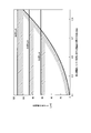
- FIG. 7 shows the measurement results of the relationship between the maximum value of strain applied to the longitudinal direction of the optical fiber in the cable and the bending radius of the cable when the optical fiber cable, the single-core optical fiber cable, and the tape optical fiber cable according to the embodiment of the present invention are bent.
- FIG. 7 shows the result of measuring the maximum value of strain applied in the longitudinal direction of the optical fiber by changing the bending radius of the optical fiber cable according to the present embodiment.
- the results for the above-described single-core optical fiber cable and tape-core optical fiber cable are also shown.
- Fig. 7 shows that the strain increases as the cable bend radius decreases.
- the optical fiber cable according to the present embodiment has a strain characteristic that is almost intermediate between the two, unlike the strain characteristics of the tape core optical fiber cable and the single core optical fiber cable.
- optical fiber cables with low mounting density in the cable core and weak optical fiber tape core wire restraint in the cable are considered to have a small difference in strain characteristics due to cable bending because the optical fiber can easily move within the cable.
- the optical fiber cable according to the present embodiment has a very high cable core portion, that is, Afiber / Acore is 0.3 or more, as described in FIGS. The characteristic is greatly different from the characteristic of the optical fiber cable having the other subunit structure.
- the strain allowed for the optical fiber in the optical fiber cable is calculated by the proof strain amount and the fatigue coefficient n.
- the strain allowed for a silica-based optical fiber used in a normal environment with an n value of about 20 is required to be about 1/3 or less of the proof strain in order to ensure long-term reliability over 20 years.
- the proof strain of currently produced optical fiber is, for example, 1.0%, so that the allowable strain for the optical fiber is about 0.3%.
- residual strain, etc. remaining at the time of optical fiber cable manufacture and after laying is also superimposed on the strain generated by cable bending (about 0.1%).
- the strain needs to be about 0.2% or less.
- the tape core optical fiber cable it is about 0.3% when the bending radius is about 100 mm, and it is understood that long-term reliability cannot be ensured.
- the optical fiber cable according to the present embodiment is used with a smaller bending radius of 10 D or less, as a first method for satisfying the strain allowed for the cable bending, in the longitudinal direction of the single-core coated optical fiber, It is effective to lengthen the interval between the arranged resin parts and to make the length of the resin parts smaller than 80 mm so as to reduce the constraint imposed on the single-core coated optical fiber in the optical fiber ribbon. That is, it is effective to reduce the ratio of the length of the resin portion to the interval between the resin portions arranged in the longitudinal direction of the single-core coated optical fiber (0.4 in this embodiment). This means that when the ratio is infinitely small, it means a bundle of single-core coated optical fibers, and conversely, when the ratio is large and approaches 1 as much as possible, it means an optical fiber ribbon. I can imagine it easily.
- the 1st method for reducing the said distortion also has the effect of improving the workability
- a resin having a low Young's modulus that is, an elongation
- a material having a Young's modulus after curing lower than the Young's modulus after curing of the outermost coating resin of the single-core coated optical fiber about 250 to 1500 MPa, for example, see Patent Document 6
- a conventional single-core coating By using the resin used for the primary coating layer of the optical fiber (Young's modulus after curing is about 5-100 MPa or less, for example, see Patent Document 6), the strain generated in the longitudinal direction of the optical fiber when the optical fiber cable is bent is alleviated. Is possible.
- the second method for reducing the strain can also be separated without applying a large external force to the single-core coated optical fiber during the single-core separation operation. There is also an effect of suppressing an increase in loss.
- the present invention is not limited to the above-described embodiment as it is, and can be embodied by modifying the constituent elements without departing from the scope of the invention in the implementation stage. Further, various inventions can be formed by appropriately combining a plurality of constituent elements disclosed in the embodiment. For example, some components may be deleted from all the components shown in the embodiment. Furthermore, you may combine suitably the component covering different embodiment.
- FIG. 8A is a sectional view showing an example of the optical fiber tape according to the first embodiment of the present invention
- FIG. 8B is another view of the optical fiber tape according to the first embodiment of the present invention. It is sectional drawing which shows an example.
- 11, 12, 13, and 14 are single-core coated optical fibers, and 15, 16, and 17 are connecting portions.
- n 4 single-core coated optical fibers 11, 12, 13, and 14 having an outer diameter d ( ⁇ m) are arranged, and each single-core coated light is arranged.
- the fibers 11, 12, 13, and 14 are arranged so as not to contact each other, and n ⁇ 1, that is, the adjacent single-core coated optical fibers 11, 12, 13, and 14 are adjacent to each other by the three connecting portions 15, 16, and 17. Are continuously connected in the length direction.
- one connecting portion 16 is made of a resin having a thickness b ( ⁇ m) and a length h ( ⁇ m). .
- the thickness b of the connecting portion 16 is equal to or smaller than the outer diameter d of the single-core coated optical fibers 11, 12, 13, and 14, and b ⁇ d.
- the optical fiber of the single-core coated optical fiber is “IEC 60793-1-47 edition 2 (2006-09)“ Optical fibers ”.
- the buckling stress is an index of the ease of buckling when the optical fiber tape is subjected to a compressive load in the width direction.
- the buckling stress is a large deflection when a certain amount of stress is applied. Is the magnitude of the stress at the time of generating, and is generally represented by the formula (2-1).
- 21, 22, 23, 24, 25, 26, 27, and 28 are single-core coated optical fibers, and 31, 32, 33, 34, 35, 36, and 37 are connecting portions.
- n 8 single-core coated optical fibers 21 to 28 having an outer diameter d ( ⁇ m) are arranged so that the single-core coated optical fibers 21 to 28 do not contact each other. Adjacent single-core coated optical fibers 21 to 28 are continuously connected in the length direction by n ⁇ 1, that is, seven connecting portions 31 to 37.
- the three connecting portions 32, 34, and 36 are made of a resin having a thickness b ( ⁇ m) and a length h ( ⁇ m). ing. At this time, the thickness b of the connecting portions 32, 34, and 36 is equal to or smaller than the outer diameter d of the single-core coated optical fibers 21 to 28, and b ⁇ d.
- b / d 0.5
- a V-groove optical fiber array having a groove pitch of 250 ⁇ m as shown in Non-Patent Document 4 is used for the optical fiber alignment mechanism of the fusion splicer.
- the maximum value of the length h of the connecting portion needs to be 312.5-d ( ⁇ m).
- the length h of the connecting portion is given as a function of the thickness b of the connecting portion and the outer diameter d of the single-core coated optical fiber, and 100 (b / d) ⁇ 2 ⁇ h ⁇ 312.5 ⁇ d (where When the unit is in the range of ⁇ m), an optical fiber tape having an easily deformable shape and having an optical fiber arrangement pitch capable of multi-fiber batch connection can be realized.
- FIG. 10 is a sectional view showing an optical fiber tape according to the second embodiment of the present invention. 10, the same parts as those in FIG. 8A are denoted by the same reference numerals, and the description thereof is omitted. In FIG. 10, 41, 42, 43, and 44 are layers.
- 11 (a), (b), and (c) are cross-sectional views showing an example of an optical fiber tape according to the third embodiment of the present invention.
- FIGS. 12 (a), (b), and (c) It is sectional drawing which shows the other example of the optical fiber tape which concerns on the 3rd Embodiment of this invention.
- 11 (a), 11 (b), and 11 (c), 11 to 14 are single-core coated optical fibers, and 51 to 59 are connecting portions.
- 12 (a), 12 (b), and 12 (c), 21 to 28 are single-core coated optical fibers, and 61 to 81 are connecting portions.
- FIGS. 12 in the width direction of the optical fiber tape, the connecting portions 51-59, 61-81 The arrangement position is shifted in the thickness direction of the optical fiber tape.
- the connecting portions 54, 56, 57, 62, 66, 68, 70, 72, 74, 75, 76, 77, 79, 80, 81 are located at the centers of the single-core coated optical fibers 11-14, 21-28.
- the connecting portions 52, 55, 59, 64, 69, 71, 73 and 78 are arranged so as to be shifted from the connecting line in the thickness direction of the optical fiber tape, and the centers of the single-core coated optical fibers 11 to 14 and 21 to 28 are arranged. Is shifted from the line connecting the two to the lower side in the thickness direction of the optical fiber tape.
- a resin having a high Young's modulus of about 500 MPa to 1 GPa is used in order to integrate so as to cover the whole of a plurality of single-core coated optical fibers arranged in parallel. Even if a certain amount of compressive load is applied in the tape width direction, the single-core coated optical fiber is not easily bent without buckling.
- a resin having a low Young's modulus and a large breaking strain as a material of at least n / 2-1 connecting portions of the optical fiber tape according to the embodiment of the present invention.
- a low Young's modulus resin having a Young's modulus of 10 MPa or less which has a Young's modulus after curing of less than 500 MPa, particularly used for a primary coating layer of a single-core coated optical fiber, always has a large strain at break and excellent extensibility. It is desirable to use it.
- the optical fiber tape according to the embodiment of the present invention is easily buckled in the width direction, in order to obtain good transmission characteristics even when the optical fiber tape is buckled in the width direction in the optical fiber cable. It is desirable to use an optical fiber with reduced loss with respect to bending of the optical fiber.
- An optical fiber with reduced loss due to bending can be bent by increasing the amount of germanium or the like added to the optical fiber core, or by lowering the refractive index of the cladding from the optical fiber core by adding, for example, fluorine.
- an optical fiber that can easily confine light in an optical fiber core and guide light.
- a photonic crystal fiber that can easily confine light in the optical fiber core and can guide light even when bent in the same manner by providing holes in the cladding of the optical fiber has also been proposed.
- an optical fiber having an optical loss characteristic in which an increase in optical loss is 0.2 dB / 10 turn or less even at a bending radius of 15 mm is available.
- FIG. 13 is a cross-sectional view showing an optical fiber cable according to an embodiment of the present invention.
- 91 is an optical fiber tape according to an embodiment of the present invention
- 92 is a colored thread for identification
- 93 is a protective tape
- 94 is a jacket
- 95 is a tension member
- 97 is a string for tearing the jacket.
- an identification colored yarn 92 is provided on the outer periphery of a bundle of optical fiber tapes 91 in which a plurality of, for example, four or five optical fiber tapes 91 each consisting of four single-core-coated optical fibers are closely gathered in a straight line.
- a plurality of units for example, two units composed of four optical fiber tapes 91 and six units composed of five optical fiber tapes 91 are twisted in one direction.
- a protective tape 93 having a presser winding layer composed of a plurality of thin protective tapes is formed on the outer periphery which is densely gathered, and an outer cover 94 is applied to the outer periphery of the protective tape 93 to provide a very high density.
- a 152-core multi-fiber optical fiber cable is configured.
- a unit configured by winding an identification colored yarn around the outer periphery of an optical fiber tape bundle in which five optical fiber tapes made of four single-core coated optical fibers are closely gathered straightly is formed,
- a cable core portion having a presser winding layer composed of a plurality of thin protective tapes is formed on the outer periphery in which the ten units are twisted in one direction and densely gathered, and the outer cover is formed on the outer periphery of the cable core portion.
- the optical fiber cable according to the embodiment of the present invention includes two strength members 95 and a jacket 94, and the two strength members 95 are symmetrical to each other with respect to the center of the optical fiber cable. It is characterized in that the thickness of the outer cover 94 of the portion (projection) embedded in the outer cover 94 is thicker than the thickness of the other outer cover 94.
- a plurality of units are twisted in one direction.
- the present invention is not limited to this.
- SZ twisting having a twisted portion in the opposite direction may be performed in the middle.
- the major axis measured at the projection is, for example, 11.7 mm
- the thickness of the outer jacket excluding the protrusions is, for example, 1.9 mm.
- the area where the optical fiber is accommodated that is, the area Acore of the cable core portion is calculated from ((D-1.9 ⁇ 2) / 2) ⁇ 2 ⁇ ⁇ , for example, 27.3 mm 2 , of which 200
- d is the outer diameter (for example, 0.25) of the single-core coated optical fiber
- ⁇ is the circular ratio.
- the area Afiber occupied by a plurality of single-core coated optical fibers in the embodiment of the present invention is 9.82 mm 2 .
- the ratio of the area Afiber occupied by a plurality of single-core coated optical fibers to the area Acore of the cable core portion is Afiber / Acore ⁇ 0.36.
- the optical fiber tape is stacked, for example, the optical fiber tape is mounted in the same direction.
- the lateral pressure in the width direction is applied to the optical fiber tape accommodated therein. Since it is easily deformed even if is added, there is an effect that strain can be relaxed.
- the optical fiber tape according to the embodiment of the present invention can be easily deformed in the width direction, so that the unit can be formed in a folded state. Similar to the bundle of coated optical fibers, the cable can be manufactured.
- the optical fiber cable according to the embodiment of the present invention is different in that an optical fiber tape having a uniform structure is used continuously in the length direction, and is excellent in manufacturability. Therefore, it is advantageous in making the optical fiber cable economical.
- the cable core portion has a very high density, that is, Afiber / Acore is 0.3 or more, so that the strain characteristic with respect to cable bending is an optical fiber mounted with a conventional optical fiber tape. It is characterized by a great difference from the characteristics of the cable.
- the present invention is not limited to the above-described embodiment as it is, and can be embodied by modifying the constituent elements without departing from the scope of the invention in the implementation stage. Further, various inventions can be formed by appropriately combining a plurality of constituent elements disclosed in the embodiment. For example, some components may be deleted from all the components shown in the embodiment. Furthermore, you may combine suitably the component covering different embodiment.
- the optical fiber cable described with reference to FIGS. 1 and 13 further includes a side pressure protection layer formed of a metal tube 99 on the outer periphery of the jacket 94.
- the metal tube 99 can be a corrugated tube that has been corrugated.
- FIG. 15 is a diagram illustrating a case where the optical fiber cable described in FIG. 1 includes a metal tube 99.
- FIG. 16 is a diagram illustrating a case where the optical fiber cable described in FIG. 13 includes a metal tube 99.
- the metal tube 99 protects against the cable side pressure, so that it can be buried directly in the ground without laying in the pipe.
- 11, 12, 13, 14, 21 to 28 single-core coated optical fiber, 15, 16, 17, 31 to 37, 51 to 81: connecting portion, 41 to 44: layer, 18: resin portion, 19: non-resin Part: 91: optical fiber tape, 92: colored thread for identification, 93: protective tape, 94: jacket, 95: tensile body, 96: protrusion, 97: string for tearing the jacket.
Abstract
Description
図1は本発明の実施形態に係る光ファイバケーブルを示す断面図である。図1において、11は単心被覆光ファイバ、92は識別用糸、93は保護テープ、94は外被、95は抗張力体、96は突起部、97は切り裂き紐である。
Afiber=n×(d/2)2×π (1-1)
となる。
- part1-47 Measurement methods and test procedure - Macrobending loss”」で規定された測定方法で取得したものである。
以下図面を参照して本発明の実施の形態を詳細に説明する。図8(a)は本発明の第1の実施形態に係る光ファイバテープの一例を示す断面図であり、図8(b)は本発明の第1の実施形態に係る光ファイバテープの他の例を示す断面図である。図8(a)において、11,12,13,14は単心被覆光ファイバ、15,16,17は連結部である。
- part1-47 Measurement methods and test procedure - Macrobending loss”」に規定される測定方法で測定し、波長1.55μmにおいて半径13mmで曲げた時の光損失増加が0.2dB/10turn以下となる曲げ損失特性を有していることが好ましい。
なお、ここでEは連結部16の材料のヤング率、Iは連結部16の厚さbと奥行きからなる断面の断面二次モーメント、Aは連結部16の断面積である。仮に光ファイバテープ長さ方向に、一定長である奥行きv(μm)を仮定すると、断面二次モーメントI及び連結部16の断面積Aは式(2-2),(2-3)で与えられる。
A=vb (2-3)
Afiber=n×(d/2)2×π (2-4)
となる。ここで、nは光ファイバケーブル中の光ファイバの本数(=200)、dは単心被覆光ファイバの外径(例えば0.25)、πは円周率を意味する。
図1や図13で説明した光ファイバケーブルは、外被94の外周に金属製チューブ99で構成される側圧防護層をさらに備える。金属製チューブ99は波付加工が施されたコルゲートチューブとすることができる。図15は、図1で説明した光ファイバケーブルが金属製チューブ99を備えている場合を説明した図である。図16は、図13で説明した光ファイバケーブルが金属製チューブ99を備えている場合を説明した図である。図15や図16の光ファイバケーブルは、金属製チューブ99がケーブル側圧に対する防護となるので、管路に布設せず直接地中に埋設することができる。
Claims (22)
- 光ファイバの外周に被覆を施した3心以上の単心被覆光ファイバから構成される光ファイバテープ心線を具備した光ファイバケーブルであって、
前記光ファイバテープ心線を複数本撚り合わせたものを収容するケーブルコア部と、
前記ケーブルコア部の外周に施された外被と、
を備え、
前記光ファイバテープ心線は、隣接する2心の前記単心被覆光ファイバ同士を接着する樹脂部を長手方向及び幅方向の二次元的に複数箇所配置し、
同一の前記隣接する2心単心被覆光ファイバ間に施された前記樹脂部の長さは、同一の前記隣接する2心単心被覆光ファイバ間が接着されない非樹脂部の長さよりも短いことを特徴とする光ファイバケーブル。 - 前記光ファイバテープ心線の幅方向に隣接する前記樹脂部同士は前記光ファイバテープ心線の長手方向に互いに離れて配置されていることを特徴とする請求項1に記載の光ファイバケーブル。
- 前記単心被覆光ファイバの長手方向に配置した前記樹脂部の間隔に対する前記樹脂部の長さの比率が0.4以下であることを特徴とする請求項1又は2に記載の光ファイバケーブル。
- 前記樹脂部の長さが80mm以下であることを特徴とする請求項1から3のいずれかに記載の光ファイバケーブル。
- 前記樹脂部の材料に、前記単心被覆光ファイバの最外被覆層に用いる材料よりもヤング率が小さい材料を用いることを特徴とする請求項1から4のいずれかに記載の光ファイバケーブル。
- 前記光ファイバテープ心線は、前記光ファイバテープ心線の幅方向に前記樹脂部が全く存在しない部分を有し、前記部分の長さは、50mm以下であることを特徴とする請求項1から5のいずれかに記載の光ファイバケーブル。
- 前記光ファイバは、クラッド部に空孔を有するフォトニック結晶ファイバであることを特徴とする請求項1から6のいずれかに記載の光ファイバケーブル。
- 前記光ファイバテープ心線は、隣接する複数の前記単心被覆光ファイバのグループに分かれており、
前記樹脂部は前記グループを識別する識別機能を持つことを特徴とする請求項1から7のいずれかに記載の光ファイバケーブル。 - 前記樹脂部が持つ識別機能は、
隣接する前記グループ間における前記単心被覆光ファイバの長手方向に配置した前記樹脂部の間隔と前記グループ内における前記単心被覆光ファイバの長手方向に配置した前記樹脂部の間隔とが異なる構造で発揮されることを特徴とする請求項8に記載の光ファイバケーブル。 - 前記樹脂部が持つ識別機能は、前記樹脂部に着色した色の識別性で発揮されることを特徴とする請求項8に記載の光ファイバケーブル。
- 光ファイバの外周に被覆を施したn(nは2以上の自然数)心以上の単心被覆光ファイバと、前記単心被覆光ファイバを互いに接触しないように離れて配置し、隣接する前記単心被覆光ファイバ同士を長さ方向に連続に連結するn-1個の連結部と、を有する光ファイバテープであって、
少なくともn/2-1個の連結部において、
連結部の厚さをb、前記単心被覆光ファイバの外径をdとした時、b≦dであり、
連結部の長さhは、100(b/d)^2≦h≦312.5-d(ただし単位はμm)の範囲にあることを特徴とする光ファイバテープ。 - 前記複数の連結部のうち少なくともn/2-1個の連結部の材料には、硬化後のヤング率が500MPa未満である樹脂を用いていることを特徴とする請求項11に記載の光ファイバテープ。
- 単心被覆光ファイバの周囲に前記連結部と同じ材料の層が形成されることを特徴とする
請求項11又は12に記載の光ファイバテープ。 - 連結部が、単心被覆光ファイバの中心を結ぶ線より光ファイバテープの厚さ方向にずれ
て配置されることを特徴とする請求項11から13のいずれかに記載の光ファイバテープ。 - 前記光ファイバは、クラッド部に空孔を有するフォトニック結晶ファイバであることを特徴とする請求項11から14のいずれかに記載の光ファイバテープ。
- 請求項11から15のいずれかに記載の光ファイバテープが複数集合して収容されたことを特徴する光ファイバケーブル。
- 請求項11から15のいずれかに記載の光ファイバテープを具備した光ファイバケーブルであって、
前記光ファイバテープ心線を複数本撚り合わせたものを収容するケーブルコア部と、
前記ケーブルコア部の外周に施された外被と、
を備えることを特徴とする光ファイバケーブル。 - 前記光ファイバは、波長1.55μmにおいて半径13mmで曲げた時の光損失増加が0.2dB/10turn以下となる曲げ損失特性を有していることを特徴とする請求項1、2、3、4、5、6、7、8、9、10又は17のいずれかに記載の光ファイバケーブル。
- 前記ケーブルコア部の断面積に対する前記複数の単心被覆光ファイバが占める断面積の比が、0.3以上であることを特徴とする請求項1、2、3、4、5、6、7、8、9、17又は18に記載の光ファイバケーブル。
- 前記ケーブルコア部の中心に対して互いに対称の位置になるように前記外被に埋め込まれた2本の抗張力体をさらに備え、
前記抗張力体が埋め込まれている部分の外被の厚さが、他の部分の外被の厚さよりも厚いことを特徴とする請求項1、2、3、4、5、6、7、8、9、17、18又は19に記載の光ファイバケーブル。 - 前記外被の外周に金属製チューブで構成される側圧防護層をさらに備えることを特徴とする請求項1、2、3、4、5、6、7、8、9、17、18、19又は20に記載される光ファイバケーブル。
- 前記金属製チューブは、波付加工が施されたコルゲートチューブであることを特徴とする請求項21に記載の光ファイバケーブル。
Priority Applications (2)
| Application Number | Priority Date | Filing Date | Title |
|---|---|---|---|
| US12/996,761 US8548294B2 (en) | 2008-06-30 | 2009-05-18 | Optical fiber cable and optical fiber ribbon |
| CN200980121268.8A CN102057309B (zh) | 2008-06-30 | 2009-05-18 | 光纤缆线以及光纤带 |
Applications Claiming Priority (4)
| Application Number | Priority Date | Filing Date | Title |
|---|---|---|---|
| JP2008-170986 | 2008-06-30 | ||
| JP2008170986A JP4619424B2 (ja) | 2008-06-30 | 2008-06-30 | 光ファイバケーブル |
| JP2008-291341 | 2008-11-13 | ||
| JP2008291341A JP5235125B2 (ja) | 2008-11-13 | 2008-11-13 | 光ファイバテープ及び光ファイバケーブル |
Publications (1)
| Publication Number | Publication Date |
|---|---|
| WO2010001663A1 true WO2010001663A1 (ja) | 2010-01-07 |
Family
ID=41465766
Family Applications (1)
| Application Number | Title | Priority Date | Filing Date |
|---|---|---|---|
| PCT/JP2009/059146 WO2010001663A1 (ja) | 2008-06-30 | 2009-05-18 | 光ファイバケーブル及び光ファイバテープ |
Country Status (3)
| Country | Link |
|---|---|
| US (1) | US8548294B2 (ja) |
| CN (2) | CN102057309B (ja) |
| WO (1) | WO2010001663A1 (ja) |
Cited By (17)
| Publication number | Priority date | Publication date | Assignee | Title |
|---|---|---|---|---|
| JP2010286735A (ja) * | 2009-06-12 | 2010-12-24 | Nippon Telegr & Teleph Corp <Ntt> | 光ファイバケーブル及びその心線識別方法 |
| JP2011191587A (ja) * | 2010-03-16 | 2011-09-29 | Furukawa Electric Co Ltd:The | 光ファイバケーブル、光ファイバケーブルの分岐部形成方法、および光ファイバケーブルの敷設方法 |
| WO2012023508A1 (ja) * | 2010-08-19 | 2012-02-23 | 株式会社フジクラ | 光ファイバテープの製造方法及びこの製造方法を実行する光ファイバテープの製造装置並びにこの製造方法により製造された光ファイバテープ |
| JP2012088445A (ja) * | 2010-10-18 | 2012-05-10 | Fujikura Ltd | 光ファイバテープの製造方法及び製造装置、並びに、光ファイバテープ |
| JP2012208313A (ja) * | 2011-03-30 | 2012-10-25 | Sumitomo Electric Ind Ltd | 光ファイバテープ心線 |
| WO2013058206A1 (ja) * | 2011-10-18 | 2013-04-25 | 株式会社フジクラ | 光ファイバテープ心線及びその光ファイバテープ心線を収納した光ファイバケーブル |
| JP2014016529A (ja) * | 2012-07-10 | 2014-01-30 | Sumitomo Electric Ind Ltd | 光ファイバケーブル |
| JP2014016528A (ja) * | 2012-07-10 | 2014-01-30 | Sumitomo Electric Ind Ltd | 光ファイバテープ心線ユニットおよび光ファイバケーブル |
| US8787718B2 (en) | 2011-03-30 | 2014-07-22 | Swcc Showa Cable Systems Co., Ltd. | Optical fiber ribbon, method of manufacturing optical fiber ribbon, and optical cable |
| US20140233899A1 (en) * | 2011-09-21 | 2014-08-21 | Afl Telecommunications Llc | Optical trunk cable |
| RU2584175C2 (ru) * | 2012-03-02 | 2016-05-20 | Фудзикура Лтд. | Лента из оптических волокон и волоконно-оптический кабель, в котором заключена лента из оптических волокон |
| CN105652402A (zh) * | 2016-04-05 | 2016-06-08 | 苏州胜信光电科技有限公司 | 一种减重抗压的入室光缆 |
| JP2016146003A (ja) * | 2016-05-20 | 2016-08-12 | 日本電信電話株式会社 | 間欠接着型光ファイバテープおよびこれを用いた光ケーブル |
| CN112867952A (zh) * | 2018-11-06 | 2021-05-28 | 住友电气工业株式会社 | 光纤缆线 |
| JP2022010112A (ja) * | 2019-04-25 | 2022-01-14 | 株式会社フジクラ | 光ファイバケーブルの解体方法および光ファイバケーブル |
| WO2023113012A1 (ja) * | 2021-12-17 | 2023-06-22 | 住友電気工業株式会社 | 光ファイバケーブル |
| WO2023127828A1 (ja) * | 2021-12-27 | 2023-07-06 | 昭和電線ケーブルシステム株式会社 | 光ファイバテープ心線およびスロットレス型光ケーブル |
Families Citing this family (267)
| Publication number | Priority date | Publication date | Assignee | Title |
|---|---|---|---|---|
| US8600206B2 (en) | 2008-11-07 | 2013-12-03 | Draka Comteq, B.V. | Reduced-diameter optical fiber |
| US8805143B2 (en) * | 2009-10-19 | 2014-08-12 | Draka Comteq, B.V. | Optical-fiber cable having high fiber count and high fiber density |
| JP5309189B2 (ja) * | 2011-06-03 | 2013-10-09 | 株式会社フジクラ | 光ファイバテープ心線の製造方法及びその製造方法で製造した光ファイバテープ心線 |
| CA3178019A1 (en) * | 2012-05-02 | 2013-11-07 | Afl Telecommunications Llc | Round and small diameter optical cables with a ribbon-like optical fiber structure |
| US9091830B2 (en) | 2012-09-26 | 2015-07-28 | Corning Cable Systems Llc | Binder film for a fiber optic cable |
| US11287589B2 (en) | 2012-09-26 | 2022-03-29 | Corning Optical Communications LLC | Binder film for a fiber optic cable |
| US8620124B1 (en) | 2012-09-26 | 2013-12-31 | Corning Cable Systems Llc | Binder film for a fiber optic cable |
| US9113347B2 (en) | 2012-12-05 | 2015-08-18 | At&T Intellectual Property I, Lp | Backhaul link for distributed antenna system |
| US10009065B2 (en) | 2012-12-05 | 2018-06-26 | At&T Intellectual Property I, L.P. | Backhaul link for distributed antenna system |
| US9999038B2 (en) | 2013-05-31 | 2018-06-12 | At&T Intellectual Property I, L.P. | Remote distributed antenna system |
| US9525524B2 (en) | 2013-05-31 | 2016-12-20 | At&T Intellectual Property I, L.P. | Remote distributed antenna system |
| US9482839B2 (en) | 2013-08-09 | 2016-11-01 | Corning Cable Systems Llc | Optical fiber cable with anti-split feature |
| US9075212B2 (en) | 2013-09-24 | 2015-07-07 | Corning Optical Communications LLC | Stretchable fiber optic cable |
| US8805144B1 (en) | 2013-09-24 | 2014-08-12 | Corning Optical Communications LLC | Stretchable fiber optic cable |
| US8913862B1 (en) | 2013-09-27 | 2014-12-16 | Corning Optical Communications LLC | Optical communication cable |
| US9594226B2 (en) | 2013-10-18 | 2017-03-14 | Corning Optical Communications LLC | Optical fiber cable with reinforcement |
| US8897697B1 (en) | 2013-11-06 | 2014-11-25 | At&T Intellectual Property I, Lp | Millimeter-wave surface-wave communications |
| US9209902B2 (en) | 2013-12-10 | 2015-12-08 | At&T Intellectual Property I, L.P. | Quasi-optical coupler |
| JP2015129887A (ja) * | 2014-01-08 | 2015-07-16 | 住友電気工業株式会社 | 空気圧送用光ファイバケーブル |
| JP6228486B2 (ja) * | 2014-02-21 | 2017-11-08 | 矢崎総業株式会社 | 電線、及び、ワイヤーハーネス |
| US9389382B2 (en) | 2014-06-03 | 2016-07-12 | Corning Optical Communications LLC | Fiber optic ribbon cable and ribbon |
| US9692101B2 (en) | 2014-08-26 | 2017-06-27 | At&T Intellectual Property I, L.P. | Guided wave couplers for coupling electromagnetic waves between a waveguide surface and a surface of a wire |
| US9768833B2 (en) | 2014-09-15 | 2017-09-19 | At&T Intellectual Property I, L.P. | Method and apparatus for sensing a condition in a transmission medium of electromagnetic waves |
| US10063280B2 (en) | 2014-09-17 | 2018-08-28 | At&T Intellectual Property I, L.P. | Monitoring and mitigating conditions in a communication network |
| JP2016061871A (ja) * | 2014-09-17 | 2016-04-25 | 古河電気工業株式会社 | 光ファイバケーブル |
| JP6639773B2 (ja) * | 2014-09-17 | 2020-02-05 | 古河電気工業株式会社 | ルースチューブ型光ファイバユニット |
| US10150252B2 (en) | 2014-09-23 | 2018-12-11 | Stryker Sustainability Solutions, Inc. | Method of recoupling components during reprocessing |
| US9628854B2 (en) | 2014-09-29 | 2017-04-18 | At&T Intellectual Property I, L.P. | Method and apparatus for distributing content in a communication network |
| US9615269B2 (en) | 2014-10-02 | 2017-04-04 | At&T Intellectual Property I, L.P. | Method and apparatus that provides fault tolerance in a communication network |
| US9685992B2 (en) | 2014-10-03 | 2017-06-20 | At&T Intellectual Property I, L.P. | Circuit panel network and methods thereof |
| US9503189B2 (en) | 2014-10-10 | 2016-11-22 | At&T Intellectual Property I, L.P. | Method and apparatus for arranging communication sessions in a communication system |
| US9762289B2 (en) | 2014-10-14 | 2017-09-12 | At&T Intellectual Property I, L.P. | Method and apparatus for transmitting or receiving signals in a transportation system |
| US9973299B2 (en) | 2014-10-14 | 2018-05-15 | At&T Intellectual Property I, L.P. | Method and apparatus for adjusting a mode of communication in a communication network |
| US9577306B2 (en) | 2014-10-21 | 2017-02-21 | At&T Intellectual Property I, L.P. | Guided-wave transmission device and methods for use therewith |
| US9780834B2 (en) | 2014-10-21 | 2017-10-03 | At&T Intellectual Property I, L.P. | Method and apparatus for transmitting electromagnetic waves |
| US9627768B2 (en) | 2014-10-21 | 2017-04-18 | At&T Intellectual Property I, L.P. | Guided-wave transmission device with non-fundamental mode propagation and methods for use therewith |
| US9653770B2 (en) | 2014-10-21 | 2017-05-16 | At&T Intellectual Property I, L.P. | Guided wave coupler, coupling module and methods for use therewith |
| US9520945B2 (en) | 2014-10-21 | 2016-12-13 | At&T Intellectual Property I, L.P. | Apparatus for providing communication services and methods thereof |
| US9769020B2 (en) | 2014-10-21 | 2017-09-19 | At&T Intellectual Property I, L.P. | Method and apparatus for responding to events affecting communications in a communication network |
| US9564947B2 (en) | 2014-10-21 | 2017-02-07 | At&T Intellectual Property I, L.P. | Guided-wave transmission device with diversity and methods for use therewith |
| US9312919B1 (en) | 2014-10-21 | 2016-04-12 | At&T Intellectual Property I, Lp | Transmission device with impairment compensation and methods for use therewith |
| US10009067B2 (en) | 2014-12-04 | 2018-06-26 | At&T Intellectual Property I, L.P. | Method and apparatus for configuring a communication interface |
| US9544006B2 (en) | 2014-11-20 | 2017-01-10 | At&T Intellectual Property I, L.P. | Transmission device with mode division multiplexing and methods for use therewith |
| US9997819B2 (en) | 2015-06-09 | 2018-06-12 | At&T Intellectual Property I, L.P. | Transmission medium and method for facilitating propagation of electromagnetic waves via a core |
| US10505250B2 (en) | 2014-11-20 | 2019-12-10 | At&T Intellectual Property I, L.P. | Communication system having a cable with a plurality of stranded uninsulated conductors forming interstitial areas for propagating guided wave modes therein and methods of use |
| US9654173B2 (en) | 2014-11-20 | 2017-05-16 | At&T Intellectual Property I, L.P. | Apparatus for powering a communication device and methods thereof |
| US10505252B2 (en) | 2014-11-20 | 2019-12-10 | At&T Intellectual Property I, L.P. | Communication system having a coupler for guiding electromagnetic waves through interstitial areas formed by a plurality of stranded uninsulated conductors and method of use |
| US9800327B2 (en) | 2014-11-20 | 2017-10-24 | At&T Intellectual Property I, L.P. | Apparatus for controlling operations of a communication device and methods thereof |
| US10411920B2 (en) | 2014-11-20 | 2019-09-10 | At&T Intellectual Property I, L.P. | Methods and apparatus for inducing electromagnetic waves within pathways of a cable |
| US10516555B2 (en) | 2014-11-20 | 2019-12-24 | At&T Intellectual Property I, L.P. | Methods and apparatus for creating interstitial areas in a cable |
| US11025460B2 (en) | 2014-11-20 | 2021-06-01 | At&T Intellectual Property I, L.P. | Methods and apparatus for accessing interstitial areas of a cable |
| US9954287B2 (en) | 2014-11-20 | 2018-04-24 | At&T Intellectual Property I, L.P. | Apparatus for converting wireless signals and electromagnetic waves and methods thereof |
| US10340573B2 (en) | 2016-10-26 | 2019-07-02 | At&T Intellectual Property I, L.P. | Launcher with cylindrical coupling device and methods for use therewith |
| US9742462B2 (en) | 2014-12-04 | 2017-08-22 | At&T Intellectual Property I, L.P. | Transmission medium and communication interfaces and methods for use therewith |
| US10505249B2 (en) | 2014-11-20 | 2019-12-10 | At&T Intellectual Property I, L.P. | Communication system having a cable with a plurality of stranded uninsulated conductors forming interstitial areas for guiding electromagnetic waves therein and method of use |
| US9461706B1 (en) | 2015-07-31 | 2016-10-04 | At&T Intellectual Property I, Lp | Method and apparatus for exchanging communication signals |
| US10505248B2 (en) | 2014-11-20 | 2019-12-10 | At&T Intellectual Property I, L.P. | Communication cable having a plurality of uninsulated conductors forming interstitial areas for propagating electromagnetic waves therein and method of use |
| US9680670B2 (en) | 2014-11-20 | 2017-06-13 | At&T Intellectual Property I, L.P. | Transmission device with channel equalization and control and methods for use therewith |
| US10554454B2 (en) | 2014-11-20 | 2020-02-04 | At&T Intellectual Property I, L.P. | Methods and apparatus for inducing electromagnetic waves in a cable |
| JP6412779B2 (ja) * | 2014-11-20 | 2018-10-24 | 株式会社フジクラ | 光ファイバテープ心線、光ファイバケーブル、および、光ファイバテープ心線の製造方法 |
| US10243784B2 (en) | 2014-11-20 | 2019-03-26 | At&T Intellectual Property I, L.P. | System for generating topology information and methods thereof |
| JP6408389B2 (ja) * | 2015-01-26 | 2018-10-17 | 株式会社フジクラ | 光ファイバテープの製造方法、異常検出方法及び製造システム |
| US10144036B2 (en) | 2015-01-30 | 2018-12-04 | At&T Intellectual Property I, L.P. | Method and apparatus for mitigating interference affecting a propagation of electromagnetic waves guided by a transmission medium |
| US9876570B2 (en) | 2015-02-20 | 2018-01-23 | At&T Intellectual Property I, Lp | Guided-wave transmission device with non-fundamental mode propagation and methods for use therewith |
| US9749013B2 (en) | 2015-03-17 | 2017-08-29 | At&T Intellectual Property I, L.P. | Method and apparatus for reducing attenuation of electromagnetic waves guided by a transmission medium |
| JP5925930B1 (ja) | 2015-03-18 | 2016-05-25 | 日本航空電子工業株式会社 | 光ファイバケーブルアセンブリ及び測定装置 |
| US9705561B2 (en) | 2015-04-24 | 2017-07-11 | At&T Intellectual Property I, L.P. | Directional coupling device and methods for use therewith |
| US10224981B2 (en) | 2015-04-24 | 2019-03-05 | At&T Intellectual Property I, Lp | Passive electrical coupling device and methods for use therewith |
| US9793954B2 (en) | 2015-04-28 | 2017-10-17 | At&T Intellectual Property I, L.P. | Magnetic coupling device and methods for use therewith |
| US9948354B2 (en) | 2015-04-28 | 2018-04-17 | At&T Intellectual Property I, L.P. | Magnetic coupling device with reflective plate and methods for use therewith |
| US9490869B1 (en) | 2015-05-14 | 2016-11-08 | At&T Intellectual Property I, L.P. | Transmission medium having multiple cores and methods for use therewith |
| US9871282B2 (en) | 2015-05-14 | 2018-01-16 | At&T Intellectual Property I, L.P. | At least one transmission medium having a dielectric surface that is covered at least in part by a second dielectric |
| US9748626B2 (en) | 2015-05-14 | 2017-08-29 | At&T Intellectual Property I, L.P. | Plurality of cables having different cross-sectional shapes which are bundled together to form a transmission medium |
| US10679767B2 (en) | 2015-05-15 | 2020-06-09 | At&T Intellectual Property I, L.P. | Transmission medium having a conductive material and methods for use therewith |
| US10650940B2 (en) | 2015-05-15 | 2020-05-12 | At&T Intellectual Property I, L.P. | Transmission medium having a conductive material and methods for use therewith |
| US9917341B2 (en) | 2015-05-27 | 2018-03-13 | At&T Intellectual Property I, L.P. | Apparatus and method for launching electromagnetic waves and for modifying radial dimensions of the propagating electromagnetic waves |
| US10103801B2 (en) | 2015-06-03 | 2018-10-16 | At&T Intellectual Property I, L.P. | Host node device and methods for use therewith |
| WO2016196419A1 (en) * | 2015-06-03 | 2016-12-08 | Corning Optical Communications LLC | Optical fiber cable with bonded core elements |
| US9866309B2 (en) | 2015-06-03 | 2018-01-09 | At&T Intellectual Property I, Lp | Host node device and methods for use therewith |
| US10348391B2 (en) | 2015-06-03 | 2019-07-09 | At&T Intellectual Property I, L.P. | Client node device with frequency conversion and methods for use therewith |
| US10812174B2 (en) | 2015-06-03 | 2020-10-20 | At&T Intellectual Property I, L.P. | Client node device and methods for use therewith |
| US10154493B2 (en) | 2015-06-03 | 2018-12-11 | At&T Intellectual Property I, L.P. | Network termination and methods for use therewith |
| US9912381B2 (en) | 2015-06-03 | 2018-03-06 | At&T Intellectual Property I, Lp | Network termination and methods for use therewith |
| US9913139B2 (en) | 2015-06-09 | 2018-03-06 | At&T Intellectual Property I, L.P. | Signal fingerprinting for authentication of communicating devices |
| US9608692B2 (en) | 2015-06-11 | 2017-03-28 | At&T Intellectual Property I, L.P. | Repeater and methods for use therewith |
| US10142086B2 (en) | 2015-06-11 | 2018-11-27 | At&T Intellectual Property I, L.P. | Repeater and methods for use therewith |
| US9820146B2 (en) | 2015-06-12 | 2017-11-14 | At&T Intellectual Property I, L.P. | Method and apparatus for authentication and identity management of communicating devices |
| US9667317B2 (en) | 2015-06-15 | 2017-05-30 | At&T Intellectual Property I, L.P. | Method and apparatus for providing security using network traffic adjustments |
| US9509415B1 (en) | 2015-06-25 | 2016-11-29 | At&T Intellectual Property I, L.P. | Methods and apparatus for inducing a fundamental wave mode on a transmission medium |
| US9640850B2 (en) | 2015-06-25 | 2017-05-02 | At&T Intellectual Property I, L.P. | Methods and apparatus for inducing a non-fundamental wave mode on a transmission medium |
| US9865911B2 (en) | 2015-06-25 | 2018-01-09 | At&T Intellectual Property I, L.P. | Waveguide system for slot radiating first electromagnetic waves that are combined into a non-fundamental wave mode second electromagnetic wave on a transmission medium |
| US10205655B2 (en) | 2015-07-14 | 2019-02-12 | At&T Intellectual Property I, L.P. | Apparatus and methods for communicating utilizing an antenna array and multiple communication paths |
| US10033107B2 (en) | 2015-07-14 | 2018-07-24 | At&T Intellectual Property I, L.P. | Method and apparatus for coupling an antenna to a device |
| US9853342B2 (en) | 2015-07-14 | 2017-12-26 | At&T Intellectual Property I, L.P. | Dielectric transmission medium connector and methods for use therewith |
| US10033108B2 (en) | 2015-07-14 | 2018-07-24 | At&T Intellectual Property I, L.P. | Apparatus and methods for generating an electromagnetic wave having a wave mode that mitigates interference |
| US10148016B2 (en) | 2015-07-14 | 2018-12-04 | At&T Intellectual Property I, L.P. | Apparatus and methods for communicating utilizing an antenna array |
| US10170840B2 (en) | 2015-07-14 | 2019-01-01 | At&T Intellectual Property I, L.P. | Apparatus and methods for sending or receiving electromagnetic signals |
| US9847566B2 (en) | 2015-07-14 | 2017-12-19 | At&T Intellectual Property I, L.P. | Method and apparatus for adjusting a field of a signal to mitigate interference |
| US10320586B2 (en) | 2015-07-14 | 2019-06-11 | At&T Intellectual Property I, L.P. | Apparatus and methods for generating non-interfering electromagnetic waves on an insulated transmission medium |
| US10044409B2 (en) | 2015-07-14 | 2018-08-07 | At&T Intellectual Property I, L.P. | Transmission medium and methods for use therewith |
| US10341142B2 (en) | 2015-07-14 | 2019-07-02 | At&T Intellectual Property I, L.P. | Apparatus and methods for generating non-interfering electromagnetic waves on an uninsulated conductor |
| US9836957B2 (en) | 2015-07-14 | 2017-12-05 | At&T Intellectual Property I, L.P. | Method and apparatus for communicating with premises equipment |
| US9882257B2 (en) | 2015-07-14 | 2018-01-30 | At&T Intellectual Property I, L.P. | Method and apparatus for launching a wave mode that mitigates interference |
| US9628116B2 (en) | 2015-07-14 | 2017-04-18 | At&T Intellectual Property I, L.P. | Apparatus and methods for transmitting wireless signals |
| US9722318B2 (en) | 2015-07-14 | 2017-08-01 | At&T Intellectual Property I, L.P. | Method and apparatus for coupling an antenna to a device |
| US10090606B2 (en) | 2015-07-15 | 2018-10-02 | At&T Intellectual Property I, L.P. | Antenna system with dielectric array and methods for use therewith |
| US9608740B2 (en) | 2015-07-15 | 2017-03-28 | At&T Intellectual Property I, L.P. | Method and apparatus for launching a wave mode that mitigates interference |
| US9793951B2 (en) | 2015-07-15 | 2017-10-17 | At&T Intellectual Property I, L.P. | Method and apparatus for launching a wave mode that mitigates interference |
| US9912027B2 (en) | 2015-07-23 | 2018-03-06 | At&T Intellectual Property I, L.P. | Method and apparatus for exchanging communication signals |
| US9948333B2 (en) | 2015-07-23 | 2018-04-17 | At&T Intellectual Property I, L.P. | Method and apparatus for wireless communications to mitigate interference |
| US10784670B2 (en) | 2015-07-23 | 2020-09-22 | At&T Intellectual Property I, L.P. | Antenna support for aligning an antenna |
| US9871283B2 (en) | 2015-07-23 | 2018-01-16 | At&T Intellectual Property I, Lp | Transmission medium having a dielectric core comprised of plural members connected by a ball and socket configuration |
| US9749053B2 (en) | 2015-07-23 | 2017-08-29 | At&T Intellectual Property I, L.P. | Node device, repeater and methods for use therewith |
| US10020587B2 (en) | 2015-07-31 | 2018-07-10 | At&T Intellectual Property I, L.P. | Radial antenna and methods for use therewith |
| JP6641480B2 (ja) | 2015-07-31 | 2020-02-05 | コーニング オプティカル コミュニケイションズ リミテッド ライアビリティ カンパニー | ロール可能な光ファイバリボン |
| US10514517B2 (en) * | 2015-07-31 | 2019-12-24 | Sumitomo Electric Industries, Ltd. | Optical fiber cable |
| US9735833B2 (en) | 2015-07-31 | 2017-08-15 | At&T Intellectual Property I, L.P. | Method and apparatus for communications management in a neighborhood network |
| US9967173B2 (en) | 2015-07-31 | 2018-05-08 | At&T Intellectual Property I, L.P. | Method and apparatus for authentication and identity management of communicating devices |
| CN105116487A (zh) * | 2015-09-01 | 2015-12-02 | 昂纳信息技术(深圳)有限公司 | 一种将散光纤并成带纤的工装及其并带方法 |
| US9904535B2 (en) | 2015-09-14 | 2018-02-27 | At&T Intellectual Property I, L.P. | Method and apparatus for distributing software |
| US10051629B2 (en) | 2015-09-16 | 2018-08-14 | At&T Intellectual Property I, L.P. | Method and apparatus for use with a radio distributed antenna system having an in-band reference signal |
| US10136434B2 (en) | 2015-09-16 | 2018-11-20 | At&T Intellectual Property I, L.P. | Method and apparatus for use with a radio distributed antenna system having an ultra-wideband control channel |
| US10009063B2 (en) | 2015-09-16 | 2018-06-26 | At&T Intellectual Property I, L.P. | Method and apparatus for use with a radio distributed antenna system having an out-of-band reference signal |
| US10079661B2 (en) | 2015-09-16 | 2018-09-18 | At&T Intellectual Property I, L.P. | Method and apparatus for use with a radio distributed antenna system having a clock reference |
| US9705571B2 (en) | 2015-09-16 | 2017-07-11 | At&T Intellectual Property I, L.P. | Method and apparatus for use with a radio distributed antenna system |
| US10009901B2 (en) | 2015-09-16 | 2018-06-26 | At&T Intellectual Property I, L.P. | Method, apparatus, and computer-readable storage medium for managing utilization of wireless resources between base stations |
| JP6569429B2 (ja) * | 2015-09-25 | 2019-09-04 | 住友電気工業株式会社 | 光ファイバテープ心線 |
| US9769128B2 (en) | 2015-09-28 | 2017-09-19 | At&T Intellectual Property I, L.P. | Method and apparatus for encryption of communications over a network |
| US9729197B2 (en) | 2015-10-01 | 2017-08-08 | At&T Intellectual Property I, L.P. | Method and apparatus for communicating network management traffic over a network |
| US9876264B2 (en) | 2015-10-02 | 2018-01-23 | At&T Intellectual Property I, Lp | Communication system, guided wave switch and methods for use therewith |
| US10074890B2 (en) | 2015-10-02 | 2018-09-11 | At&T Intellectual Property I, L.P. | Communication device and antenna with integrated light assembly |
| US9882277B2 (en) | 2015-10-02 | 2018-01-30 | At&T Intellectual Property I, Lp | Communication device and antenna assembly with actuated gimbal mount |
| US10355367B2 (en) | 2015-10-16 | 2019-07-16 | At&T Intellectual Property I, L.P. | Antenna structure for exchanging wireless signals |
| US10665942B2 (en) | 2015-10-16 | 2020-05-26 | At&T Intellectual Property I, L.P. | Method and apparatus for adjusting wireless communications |
| US10051483B2 (en) | 2015-10-16 | 2018-08-14 | At&T Intellectual Property I, L.P. | Method and apparatus for directing wireless signals |
| US9869838B2 (en) * | 2015-11-25 | 2018-01-16 | Fujikura Ltd. | Optical fiber cable and method of manufacturing same |
| WO2017095544A1 (en) * | 2015-11-30 | 2017-06-08 | Corning Optical Communications LLC | Fiber-bundle assembly for maintaining a select order in an optical fiber cable |
| WO2017122518A1 (ja) * | 2016-01-13 | 2017-07-20 | 住友電気工業株式会社 | 間欠連結型光ファイバテープ心線、光ケーブルおよび間欠連結型光ファイバテープ心線の製造方法 |
| US10268009B2 (en) * | 2016-01-28 | 2019-04-23 | Sumitomo Electric Industries, Ltd. | Optical fiber cable |
| US10989888B2 (en) * | 2016-02-02 | 2021-04-27 | Ofs Fitel, Llc | Flexible ribbon structure and method for making |
| US9880368B2 (en) * | 2016-02-02 | 2018-01-30 | Ofs Fitel, Llc | Method for high speed processing of partially bonded ribbon structures |
| JP2017142285A (ja) * | 2016-02-08 | 2017-08-17 | 住友電気工業株式会社 | 光ファイバケーブル |
| EP3422062A4 (en) * | 2016-02-23 | 2019-10-23 | Sumitomo Electric Industries, Ltd. | FIBERGLASS BELT WITH BROKEN CONNECTION, MANUFACTURING METHOD FOR FIBERBAND BELT WITH BROKEN LINKAGE, FIBERGLASS BELT AND FIBER OPTIC CABLE |
| US9921380B2 (en) * | 2016-03-22 | 2018-03-20 | Ofs Fitel, Llc | Composite cable |
| US11256056B2 (en) * | 2016-04-08 | 2022-02-22 | Fujikura Ltd. | Method for manufacturing optical fiber ribbon, optical fiber ribbon, and optical cable |
| EP3258219A1 (en) * | 2016-06-15 | 2017-12-20 | Eidgenössische Materialprüfungs- und Forschungsanstalt EMPA | In-situ and real time quality control in additive manufacturing process |
| ES2801054T3 (es) | 2016-07-27 | 2021-01-08 | Prysmian Spa | Cinta de fibra óptica flexible |
| CA3033384A1 (en) * | 2016-08-08 | 2018-02-15 | Corning Optical Communications LLC | Flexible optical fiber ribbon with intermittently bonded polymer layers |
| US9912419B1 (en) | 2016-08-24 | 2018-03-06 | At&T Intellectual Property I, L.P. | Method and apparatus for managing a fault in a distributed antenna system |
| US9860075B1 (en) | 2016-08-26 | 2018-01-02 | At&T Intellectual Property I, L.P. | Method and communication node for broadband distribution |
| US10291311B2 (en) | 2016-09-09 | 2019-05-14 | At&T Intellectual Property I, L.P. | Method and apparatus for mitigating a fault in a distributed antenna system |
| US11032819B2 (en) | 2016-09-15 | 2021-06-08 | At&T Intellectual Property I, L.P. | Method and apparatus for use with a radio distributed antenna system having a control channel reference signal |
| JP6310522B2 (ja) | 2016-09-20 | 2018-04-11 | 株式会社フジクラ | 光ファイバユニットおよび光ファイバケーブル |
| US10135147B2 (en) | 2016-10-18 | 2018-11-20 | At&T Intellectual Property I, L.P. | Apparatus and methods for launching guided waves via an antenna |
| US10135146B2 (en) | 2016-10-18 | 2018-11-20 | At&T Intellectual Property I, L.P. | Apparatus and methods for launching guided waves via circuits |
| US10340600B2 (en) | 2016-10-18 | 2019-07-02 | At&T Intellectual Property I, L.P. | Apparatus and methods for launching guided waves via plural waveguide systems |
| US10374316B2 (en) | 2016-10-21 | 2019-08-06 | At&T Intellectual Property I, L.P. | System and dielectric antenna with non-uniform dielectric |
| US9876605B1 (en) | 2016-10-21 | 2018-01-23 | At&T Intellectual Property I, L.P. | Launcher and coupling system to support desired guided wave mode |
| US9991580B2 (en) | 2016-10-21 | 2018-06-05 | At&T Intellectual Property I, L.P. | Launcher and coupling system for guided wave mode cancellation |
| US10811767B2 (en) | 2016-10-21 | 2020-10-20 | At&T Intellectual Property I, L.P. | System and dielectric antenna with convex dielectric radome |
| US10312567B2 (en) | 2016-10-26 | 2019-06-04 | At&T Intellectual Property I, L.P. | Launcher with planar strip antenna and methods for use therewith |
| US10291334B2 (en) | 2016-11-03 | 2019-05-14 | At&T Intellectual Property I, L.P. | System for detecting a fault in a communication system |
| US10224634B2 (en) | 2016-11-03 | 2019-03-05 | At&T Intellectual Property I, L.P. | Methods and apparatus for adjusting an operational characteristic of an antenna |
| US10225025B2 (en) | 2016-11-03 | 2019-03-05 | At&T Intellectual Property I, L.P. | Method and apparatus for detecting a fault in a communication system |
| US10498044B2 (en) | 2016-11-03 | 2019-12-03 | At&T Intellectual Property I, L.P. | Apparatus for configuring a surface of an antenna |
| US10340601B2 (en) | 2016-11-23 | 2019-07-02 | At&T Intellectual Property I, L.P. | Multi-antenna system and methods for use therewith |
| US10090594B2 (en) | 2016-11-23 | 2018-10-02 | At&T Intellectual Property I, L.P. | Antenna system having structural configurations for assembly |
| US10340603B2 (en) | 2016-11-23 | 2019-07-02 | At&T Intellectual Property I, L.P. | Antenna system having shielded structural configurations for assembly |
| US10178445B2 (en) | 2016-11-23 | 2019-01-08 | At&T Intellectual Property I, L.P. | Methods, devices, and systems for load balancing between a plurality of waveguides |
| US10535928B2 (en) | 2016-11-23 | 2020-01-14 | At&T Intellectual Property I, L.P. | Antenna system and methods for use therewith |
| EP3548947A1 (en) * | 2016-11-29 | 2019-10-09 | Corning Optical Communications LLC | Laser sintered flexible ribbon |
| US10305190B2 (en) | 2016-12-01 | 2019-05-28 | At&T Intellectual Property I, L.P. | Reflecting dielectric antenna system and methods for use therewith |
| US10361489B2 (en) | 2016-12-01 | 2019-07-23 | At&T Intellectual Property I, L.P. | Dielectric dish antenna system and methods for use therewith |
| US10326494B2 (en) | 2016-12-06 | 2019-06-18 | At&T Intellectual Property I, L.P. | Apparatus for measurement de-embedding and methods for use therewith |
| US10020844B2 (en) | 2016-12-06 | 2018-07-10 | T&T Intellectual Property I, L.P. | Method and apparatus for broadcast communication via guided waves |
| US10727599B2 (en) | 2016-12-06 | 2020-07-28 | At&T Intellectual Property I, L.P. | Launcher with slot antenna and methods for use therewith |
| US9927517B1 (en) | 2016-12-06 | 2018-03-27 | At&T Intellectual Property I, L.P. | Apparatus and methods for sensing rainfall |
| US10637149B2 (en) | 2016-12-06 | 2020-04-28 | At&T Intellectual Property I, L.P. | Injection molded dielectric antenna and methods for use therewith |
| US10694379B2 (en) * | 2016-12-06 | 2020-06-23 | At&T Intellectual Property I, L.P. | Waveguide system with device-based authentication and methods for use therewith |
| US10439675B2 (en) | 2016-12-06 | 2019-10-08 | At&T Intellectual Property I, L.P. | Method and apparatus for repeating guided wave communication signals |
| US10819035B2 (en) | 2016-12-06 | 2020-10-27 | At&T Intellectual Property I, L.P. | Launcher with helical antenna and methods for use therewith |
| US10382976B2 (en) | 2016-12-06 | 2019-08-13 | At&T Intellectual Property I, L.P. | Method and apparatus for managing wireless communications based on communication paths and network device positions |
| US10135145B2 (en) | 2016-12-06 | 2018-11-20 | At&T Intellectual Property I, L.P. | Apparatus and methods for generating an electromagnetic wave along a transmission medium |
| US10755542B2 (en) | 2016-12-06 | 2020-08-25 | At&T Intellectual Property I, L.P. | Method and apparatus for surveillance via guided wave communication |
| US10139820B2 (en) | 2016-12-07 | 2018-11-27 | At&T Intellectual Property I, L.P. | Method and apparatus for deploying equipment of a communication system |
| US10243270B2 (en) | 2016-12-07 | 2019-03-26 | At&T Intellectual Property I, L.P. | Beam adaptive multi-feed dielectric antenna system and methods for use therewith |
| US10168695B2 (en) | 2016-12-07 | 2019-01-01 | At&T Intellectual Property I, L.P. | Method and apparatus for controlling an unmanned aircraft |
| US9893795B1 (en) | 2016-12-07 | 2018-02-13 | At&T Intellectual Property I, Lp | Method and repeater for broadband distribution |
| US10547348B2 (en) | 2016-12-07 | 2020-01-28 | At&T Intellectual Property I, L.P. | Method and apparatus for switching transmission mediums in a communication system |
| US10027397B2 (en) | 2016-12-07 | 2018-07-17 | At&T Intellectual Property I, L.P. | Distributed antenna system and methods for use therewith |
| US10446936B2 (en) | 2016-12-07 | 2019-10-15 | At&T Intellectual Property I, L.P. | Multi-feed dielectric antenna system and methods for use therewith |
| US10389029B2 (en) | 2016-12-07 | 2019-08-20 | At&T Intellectual Property I, L.P. | Multi-feed dielectric antenna system with core selection and methods for use therewith |
| US10359749B2 (en) | 2016-12-07 | 2019-07-23 | At&T Intellectual Property I, L.P. | Method and apparatus for utilities management via guided wave communication |
| US9911020B1 (en) | 2016-12-08 | 2018-03-06 | At&T Intellectual Property I, L.P. | Method and apparatus for tracking via a radio frequency identification device |
| US10938108B2 (en) | 2016-12-08 | 2021-03-02 | At&T Intellectual Property I, L.P. | Frequency selective multi-feed dielectric antenna system and methods for use therewith |
| US10777873B2 (en) | 2016-12-08 | 2020-09-15 | At&T Intellectual Property I, L.P. | Method and apparatus for mounting network devices |
| US10530505B2 (en) | 2016-12-08 | 2020-01-07 | At&T Intellectual Property I, L.P. | Apparatus and methods for launching electromagnetic waves along a transmission medium |
| US10069535B2 (en) | 2016-12-08 | 2018-09-04 | At&T Intellectual Property I, L.P. | Apparatus and methods for launching electromagnetic waves having a certain electric field structure |
| US10601494B2 (en) | 2016-12-08 | 2020-03-24 | At&T Intellectual Property I, L.P. | Dual-band communication device and method for use therewith |
| US10389037B2 (en) | 2016-12-08 | 2019-08-20 | At&T Intellectual Property I, L.P. | Apparatus and methods for selecting sections of an antenna array and use therewith |
| US10326689B2 (en) | 2016-12-08 | 2019-06-18 | At&T Intellectual Property I, L.P. | Method and system for providing alternative communication paths |
| US9998870B1 (en) | 2016-12-08 | 2018-06-12 | At&T Intellectual Property I, L.P. | Method and apparatus for proximity sensing |
| US10411356B2 (en) | 2016-12-08 | 2019-09-10 | At&T Intellectual Property I, L.P. | Apparatus and methods for selectively targeting communication devices with an antenna array |
| US10916969B2 (en) | 2016-12-08 | 2021-02-09 | At&T Intellectual Property I, L.P. | Method and apparatus for providing power using an inductive coupling |
| US10103422B2 (en) | 2016-12-08 | 2018-10-16 | At&T Intellectual Property I, L.P. | Method and apparatus for mounting network devices |
| US9838896B1 (en) | 2016-12-09 | 2017-12-05 | At&T Intellectual Property I, L.P. | Method and apparatus for assessing network coverage |
| US10340983B2 (en) | 2016-12-09 | 2019-07-02 | At&T Intellectual Property I, L.P. | Method and apparatus for surveying remote sites via guided wave communications |
| US10264586B2 (en) | 2016-12-09 | 2019-04-16 | At&T Mobility Ii Llc | Cloud-based packet controller and methods for use therewith |
| EP3561564A4 (en) * | 2016-12-20 | 2020-07-22 | Furukawa Electric Co., Ltd. | FIBER OPTIC INTERMITTENT BAND CORE AND FIBER OPTIC INTERMITTENT BAND CORE MANUFACTURING PROCESS |
| US9973940B1 (en) | 2017-02-27 | 2018-05-15 | At&T Intellectual Property I, L.P. | Apparatus and methods for dynamic impedance matching of a guided wave launcher |
| US10298293B2 (en) | 2017-03-13 | 2019-05-21 | At&T Intellectual Property I, L.P. | Apparatus of communication utilizing wireless network devices |
| WO2018174004A1 (ja) * | 2017-03-21 | 2018-09-27 | 住友電気工業株式会社 | 光ファイバケーブル |
| EP3602155A1 (en) | 2017-03-21 | 2020-02-05 | Corning Research & Development Corporation | Fiber optic cable assembly with thermoplastically overcoated fusion splice, and related method and apparatus |
| CA3056060A1 (en) * | 2017-03-31 | 2018-10-04 | Afl Telecommunications Llc | Single jacket reduced diameter ruggedized fiber optic distribution cables |
| JPWO2018230618A1 (ja) * | 2017-06-14 | 2020-04-16 | 住友電気工業株式会社 | スロット型光ケーブル |
| MX2020000080A (es) * | 2017-07-05 | 2020-02-17 | Corning Res & Dev Corp | Cable plano con alta densidad de fibras. |
| EP3652575B1 (en) | 2017-07-11 | 2023-12-27 | Prysmian S.p.A. | An optical fiber ribbon and a method of producing the same |
| CA3067742C (en) | 2017-07-11 | 2024-04-02 | Prysmian S.P.A. | An optical fiber ribbon assembly and a method of producing the same |
| WO2019021998A1 (ja) | 2017-07-24 | 2019-01-31 | 住友電気工業株式会社 | 光ファイバテープ心線および光ファイバケーブル |
| EP3665521B1 (en) * | 2017-08-08 | 2023-11-08 | Corning Research & Development Corporation | Rollable optical fiber ribbon with low attenuation, large mode field diameter optical fiber and cable |
| CN111149033A (zh) * | 2017-09-21 | 2020-05-12 | 住友电气工业株式会社 | 光纤线缆 |
| CN107767995B (zh) * | 2017-09-23 | 2023-10-03 | 立讯精密工业股份有限公司 | 圆形线缆 |
| WO2019088255A1 (ja) * | 2017-11-02 | 2019-05-09 | 住友電気工業株式会社 | 光ファイバユニットおよび光ファイバケーブル |
| EP3705923A4 (en) * | 2017-11-02 | 2021-08-11 | Sumitomo Electric Industries, Ltd. | FIBER OPTIC UNIT AND FIBER OPTIC CABLE |
| JP6676032B2 (ja) * | 2017-12-21 | 2020-04-08 | 株式会社フジクラ | 光ファイバケーブル |
| US20190219783A1 (en) * | 2018-01-12 | 2019-07-18 | Ofs Fitel, Llc | Multi-fiber unit tube optical fiber microcable incorporating rollable optical fibers ribbons |
| RU2759664C1 (ru) | 2018-01-15 | 2021-11-16 | Призмиан С.П.А. | Способ изготовления гибкой волоконно-оптической ленты и лента |
| US11256051B2 (en) | 2018-01-15 | 2022-02-22 | Prysmian S.P.A. | Flexible optical-fiber ribbon |
| CN111886529B (zh) * | 2018-01-15 | 2023-08-01 | 普睿司曼股份公司 | 光纤带及其生产方法和生产系统 |
| JP7151727B2 (ja) | 2018-01-18 | 2022-10-12 | 住友電気工業株式会社 | 光ファイバケーブル |
| US11262516B2 (en) * | 2018-07-05 | 2022-03-01 | Prysmian S.P.A. | High density optical cables |
| US10718917B2 (en) | 2018-08-24 | 2020-07-21 | Prysmian S.P.A. | Flexible optical fiber ribbons and methods of formation thereof |
| CN112888978B (zh) | 2018-09-07 | 2023-01-13 | 康宁公司 | 具有用于多路熔接的带化接口的光纤扇出组件及其制造方法 |
| US10976492B2 (en) | 2018-09-07 | 2021-04-13 | Corning Incorporated | Cable with overcoated non-coplanar groups of fusion spliced optical fibers, and fabrication method |
| CN109106465A (zh) * | 2018-09-25 | 2019-01-01 | 中国科学院深圳先进技术研究院 | 一种双光纤结构及其制备方法 |
| JP7063217B2 (ja) * | 2018-09-27 | 2022-05-09 | 住友電気工業株式会社 | 光ファイバの製造方法 |
| WO2020075734A1 (ja) * | 2018-10-11 | 2020-04-16 | 株式会社フジクラ | 光ファイバケーブル |
| CN109655963B (zh) * | 2019-02-28 | 2021-04-27 | 武汉理工大学 | 一种具有定点涂层的光纤 |
| US20220196945A1 (en) * | 2019-03-20 | 2022-06-23 | Sumitomo Electric Industries, Ltd. | Intermittent connection-type optical fiber tape core, optical fiber cable and connector-equipped optical fiber cord |
| CN109975934A (zh) * | 2019-04-12 | 2019-07-05 | 汕头高新区奥星光通信设备有限公司 | 一种带标色可卷束光纤带 |
| US11131817B2 (en) | 2019-05-09 | 2021-09-28 | Go!Foton Holdings, Inc. | Multi-fiber cable |
| US10678012B1 (en) | 2019-05-22 | 2020-06-09 | Corning Research & Development Corporation | Fiber optic cable assembly with integrated shuffle and fabrication method |
| US11762161B2 (en) | 2019-06-19 | 2023-09-19 | Sumitomo Electric Industries, Ltd. | Optical fiber cable |
| US11360265B2 (en) | 2019-07-31 | 2022-06-14 | Corning Research & Development Corporation | Fiber optic cable assembly with overlapping bundled strength members, and fabrication method and apparatus |
| US11579387B2 (en) * | 2019-08-14 | 2023-02-14 | Sterlite Technologies Limited | Arrangement of optical fibre ribbon stack and an optical fibre ribbon thereof |
| EP4027180A4 (en) * | 2019-09-05 | 2022-11-02 | Sumitomo Electric Industries, Ltd. | FIBER OPTIC RIBBON, FIBER OPTIC CABLE, AND FIBER OPTIC CORD WITH CONNECTOR |
| JP7157026B2 (ja) * | 2019-09-12 | 2022-10-19 | 株式会社フジクラ | 光ファイバ整列方法、光ファイバ融着方法、コネクタ付き光ファイバテープの製造方法及び間欠連結型の光ファイバテープ |
| US10884213B1 (en) * | 2019-11-14 | 2021-01-05 | Prysmian S.P.A. | Optical-fiber ribbon with distorted sinusoidal adhesive pattern and method therefor |
| US11300749B2 (en) | 2019-11-18 | 2022-04-12 | Ofs Fitel, Llc | Preparation of fiber optic cables for duct applications |
| US11953749B2 (en) * | 2020-03-16 | 2024-04-09 | Sterlite Technologies Limited | Intermittently bonded ribbon with colored bonds |
| US11886009B2 (en) | 2020-10-01 | 2024-01-30 | Corning Research & Development Corporation | Coating fusion spliced optical fibers and subsequent processing methods thereof |
| US11808983B2 (en) | 2020-11-24 | 2023-11-07 | Corning Research & Development Corporation | Multi-fiber splice protector with compact splice-on furcation housing |
| US11442238B2 (en) | 2020-12-22 | 2022-09-13 | Prysmian S.P.A. | Optical-fiber ribbon with spaced optical-fiber units |
| US11860429B2 (en) | 2020-12-22 | 2024-01-02 | Prysmian S.P.A. | Optical-fiber ribbon with spaced optical-fiber units |
| US11460652B2 (en) | 2020-12-22 | 2022-10-04 | Prysmian S.P.A. | Optical-fiber ribbon with adhesive-free gaps |
| US11867947B2 (en) | 2021-04-30 | 2024-01-09 | Corning Research & Development Corporation | Cable assembly having routable splice protectors |
| CN113359230B (zh) * | 2021-05-18 | 2022-04-29 | 烽火通信科技股份有限公司 | 一种柔性光纤带及光缆 |
| CN113311535B (zh) * | 2021-05-18 | 2022-05-17 | 烽火通信科技股份有限公司 | 一种光纤带及光缆 |
| EP4348317A1 (en) * | 2021-06-02 | 2024-04-10 | Corning Research & Development Corporation | High core density optical fiber cables |
| WO2023081039A1 (en) * | 2021-11-03 | 2023-05-11 | Corning Research & Development Corporation | Optical fiber ribbon configured to maintain orientation of polarization-maintaining and multicore optical fibers |
| CN114217398B (zh) * | 2021-12-20 | 2023-03-24 | 长飞光纤光缆股份有限公司 | 柔性光纤带的成型方法及用于实施该成型方法的点胶设备 |
| CN114047587B (zh) * | 2022-01-13 | 2022-04-22 | 长飞光纤光缆股份有限公司 | 一种固化包束层绞式光缆及其制备方法 |
| CN114384657B (zh) * | 2022-03-25 | 2022-08-02 | 长飞光纤光缆股份有限公司 | 一种阻水柔性光纤带以及全干式高密度光缆 |
| WO2023205446A1 (en) * | 2022-04-21 | 2023-10-26 | Commscope Technologies Llc | Rolled fiber ribbon and method for manufacturing |
| CN114927282B (zh) * | 2022-05-23 | 2023-05-12 | 长飞光电线缆(苏州)有限公司 | 一种具有弯曲套管的光纤带光缆 |
| CN115144957B (zh) * | 2022-09-06 | 2022-11-04 | 江苏中天科技股份有限公司 | 一种可定向卷绕式柔性光纤带及其光缆 |
| CN115144956B (zh) * | 2022-09-06 | 2022-11-04 | 江苏中天科技股份有限公司 | 一种柔性光纤带及带状光缆 |
Citations (4)
| Publication number | Priority date | Publication date | Assignee | Title |
|---|---|---|---|---|
| JP2002048955A (ja) * | 2000-08-02 | 2002-02-15 | Sumitomo Electric Ind Ltd | 光ファイバテープ心線とその製造方法 |
| WO2006098471A1 (ja) * | 2005-03-18 | 2006-09-21 | The Furukawa Electric Co., Ltd. | 光ファイバおよび導波路 |
| JP2007011019A (ja) * | 2005-06-30 | 2007-01-18 | Sumitomo Electric Ind Ltd | 光ファイバケーブル |
| JP2007279226A (ja) * | 2006-04-04 | 2007-10-25 | Fujikura Ltd | 光ファイバテープ心線及び前記光ファイバテープ心線を収納した光ファイバケーブル |
Family Cites Families (11)
| Publication number | Priority date | Publication date | Assignee | Title |
|---|---|---|---|---|
| JPH05281444A (ja) | 1992-04-03 | 1993-10-29 | Nippon Steel Weld Prod & Eng Co Ltd | 多心光ファイバケーブル |
| JP3560687B2 (ja) | 1995-06-08 | 2004-09-02 | 昭和電線電纜株式会社 | 光ファイバケーブル |
| US5802236A (en) * | 1997-02-14 | 1998-09-01 | Lucent Technologies Inc. | Article comprising a micro-structured optical fiber, and method of making such fiber |
| US6259844B1 (en) * | 1997-12-15 | 2001-07-10 | Siecor Operations, Llc | Strengthened fiber optic cable |
| US6584257B1 (en) * | 2000-12-27 | 2003-06-24 | Corning Cable Systems, Llc | Fiber optic assembly and method of making same |
| JP3912532B2 (ja) | 2002-02-21 | 2007-05-09 | 住友電気工業株式会社 | 被覆光ファイバ心線、コネクタ付被覆光ファイバ心線、及び、光ファイバケーブル |
| JP4049154B2 (ja) | 2002-05-28 | 2008-02-20 | 住友電気工業株式会社 | 光ファイバテープ心線 |
| JP4055000B2 (ja) | 2003-08-11 | 2008-03-05 | 住友電気工業株式会社 | 光ファイバケーブル、光ファイバケーブルの製造方法及び光ファイバケーブルの製造装置 |
| US6973246B2 (en) * | 2004-04-28 | 2005-12-06 | Furukawa Electric North America, Inc. | High count optical fiber cable |
| JP4774337B2 (ja) | 2005-07-08 | 2011-09-14 | 日本電信電話株式会社 | 多心光ファイバケーブル |
| JP5309189B2 (ja) * | 2011-06-03 | 2013-10-09 | 株式会社フジクラ | 光ファイバテープ心線の製造方法及びその製造方法で製造した光ファイバテープ心線 |
-
2009
- 2009-05-18 US US12/996,761 patent/US8548294B2/en active Active
- 2009-05-18 WO PCT/JP2009/059146 patent/WO2010001663A1/ja active Application Filing
- 2009-05-18 CN CN200980121268.8A patent/CN102057309B/zh active Active
- 2009-05-18 CN CN201210132063.3A patent/CN102681119B/zh active Active
Patent Citations (4)
| Publication number | Priority date | Publication date | Assignee | Title |
|---|---|---|---|---|
| JP2002048955A (ja) * | 2000-08-02 | 2002-02-15 | Sumitomo Electric Ind Ltd | 光ファイバテープ心線とその製造方法 |
| WO2006098471A1 (ja) * | 2005-03-18 | 2006-09-21 | The Furukawa Electric Co., Ltd. | 光ファイバおよび導波路 |
| JP2007011019A (ja) * | 2005-06-30 | 2007-01-18 | Sumitomo Electric Ind Ltd | 光ファイバケーブル |
| JP2007279226A (ja) * | 2006-04-04 | 2007-10-25 | Fujikura Ltd | 光ファイバテープ心線及び前記光ファイバテープ心線を収納した光ファイバケーブル |
Non-Patent Citations (2)
| Title |
|---|
| KUNIHIRO TOGE ET AL.: "Chosaikei·Komitsudo Hikari Faiber Cable no Tashinka ni Kansuru Kento", 2008 NEN THE INSTITUTE OF ELECTRONICS, INFORMATION AND COMMUNICATION ENGINEERS SOGO TAIKAI KOEN RONBUNSHU TSUSHIN 2, 5 March 2008 (2008-03-05), pages 453 * |
| YUSUKE YAMADA ET AL.: "Shinkei·Komitsudo 100 Shinko Cable no Kiso Kento", 2006 NEN DENSHI JOHO TSUSHIN GAKKAI TSUSHIN SOCIETY TAIKAI KOEN RONBUNSHU 2, 7 September 2006 (2006-09-07), pages 339 * |
Cited By (33)
| Publication number | Priority date | Publication date | Assignee | Title |
|---|---|---|---|---|
| JP2010286735A (ja) * | 2009-06-12 | 2010-12-24 | Nippon Telegr & Teleph Corp <Ntt> | 光ファイバケーブル及びその心線識別方法 |
| JP2011191587A (ja) * | 2010-03-16 | 2011-09-29 | Furukawa Electric Co Ltd:The | 光ファイバケーブル、光ファイバケーブルの分岐部形成方法、および光ファイバケーブルの敷設方法 |
| WO2012023508A1 (ja) * | 2010-08-19 | 2012-02-23 | 株式会社フジクラ | 光ファイバテープの製造方法及びこの製造方法を実行する光ファイバテープの製造装置並びにこの製造方法により製造された光ファイバテープ |
| JP2012042749A (ja) * | 2010-08-19 | 2012-03-01 | Fujikura Ltd | 光ファイバテープの製造方法及びこの製造方法を実行する光ファイバテープの製造装置並びにこの製造方法により製造された光ファイバテープ |
| CN103069322A (zh) * | 2010-08-19 | 2013-04-24 | 株式会社藤仓 | 光纤带的制造方法、执行该制造方法的光纤带的制造装置及由该制造方法制造的光纤带 |
| US9389386B2 (en) | 2010-08-19 | 2016-07-12 | Fujikura Ltd. | Manufacturing method of optical fiber ribbon, manufacturing device for optical fiber ribbon implementing said manufacturing method, and optical fiber ribbon manufactured with said manufacturing method |
| AU2011291785B2 (en) * | 2010-08-19 | 2013-11-21 | Fujikura Ltd. | Optical fiber tape manufacturing method, optical fiber tape manufacturing device implementing said manufacturing method, and optical fiber tape manufactured with said manufacturing method |
| CN103069322B (zh) * | 2010-08-19 | 2015-07-08 | 株式会社藤仓 | 光纤带的制造方法、执行该制造方法的光纤带的制造装置及由该制造方法制造的光纤带 |
| JP2012088445A (ja) * | 2010-10-18 | 2012-05-10 | Fujikura Ltd | 光ファイバテープの製造方法及び製造装置、並びに、光ファイバテープ |
| US8787718B2 (en) | 2011-03-30 | 2014-07-22 | Swcc Showa Cable Systems Co., Ltd. | Optical fiber ribbon, method of manufacturing optical fiber ribbon, and optical cable |
| JP2012208313A (ja) * | 2011-03-30 | 2012-10-25 | Sumitomo Electric Ind Ltd | 光ファイバテープ心線 |
| US20140233899A1 (en) * | 2011-09-21 | 2014-08-21 | Afl Telecommunications Llc | Optical trunk cable |
| US9995896B2 (en) | 2011-10-18 | 2018-06-12 | Fujikura Ltd. | Optical fiber ribbon and optical fiber cable housing optical fiber ribbon |
| US20220317398A1 (en) * | 2011-10-18 | 2022-10-06 | Fujikura Ltd. | Optical fiber ribbon and optical fiber cable housing optical fiber ribbon |
| US11892694B2 (en) | 2011-10-18 | 2024-02-06 | Fujikura Ltd. | Optical fiber ribbon and optical fiber cable housing optical fiber ribbon |
| US11422325B2 (en) | 2011-10-18 | 2022-08-23 | Fujikura Ltd. | Optical fiber ribbon and optical fiber cable housing optical fiber ribbon |
| WO2013058206A1 (ja) * | 2011-10-18 | 2013-04-25 | 株式会社フジクラ | 光ファイバテープ心線及びその光ファイバテープ心線を収納した光ファイバケーブル |
| US20160161692A1 (en) * | 2011-10-18 | 2016-06-09 | Nippon Telegraph And Telephone Corporation | Optical fiber ribbon and optical fiber cable housing optical fiber ribbon |
| RU2589445C2 (ru) * | 2011-10-18 | 2016-07-10 | Фудзикура Лтд. | Оптоволоконная лента и оптоволоконный кабель, в котором установлена оптоволоконная лента |
| JP2013088617A (ja) * | 2011-10-18 | 2013-05-13 | Fujikura Ltd | 光ファイバテープ心線及びその光ファイバテープ心線を収納した光ファイバケーブル |
| US20170184803A1 (en) * | 2011-10-18 | 2017-06-29 | Fujikura, Ltd. | Optical fiber ribbon and optical fiber cable housing optical fiber ribbon |
| US20170115461A1 (en) * | 2011-10-18 | 2017-04-27 | Fujikura, Ltd. | Optical fiber ribbon and optical fiber cable housing optical fiber ribbon |
| US9739965B2 (en) | 2012-03-02 | 2017-08-22 | Fujikura Ltd. | Optical fiber ribbon and optical fiber cable housing the optical fiber ribbon |
| RU2584175C2 (ru) * | 2012-03-02 | 2016-05-20 | Фудзикура Лтд. | Лента из оптических волокон и волоконно-оптический кабель, в котором заключена лента из оптических волокон |
| JP2014016528A (ja) * | 2012-07-10 | 2014-01-30 | Sumitomo Electric Ind Ltd | 光ファイバテープ心線ユニットおよび光ファイバケーブル |
| JP2014016529A (ja) * | 2012-07-10 | 2014-01-30 | Sumitomo Electric Ind Ltd | 光ファイバケーブル |
| CN105652402A (zh) * | 2016-04-05 | 2016-06-08 | 苏州胜信光电科技有限公司 | 一种减重抗压的入室光缆 |
| JP2016146003A (ja) * | 2016-05-20 | 2016-08-12 | 日本電信電話株式会社 | 間欠接着型光ファイバテープおよびこれを用いた光ケーブル |
| CN112867952A (zh) * | 2018-11-06 | 2021-05-28 | 住友电气工业株式会社 | 光纤缆线 |
| JP2022010112A (ja) * | 2019-04-25 | 2022-01-14 | 株式会社フジクラ | 光ファイバケーブルの解体方法および光ファイバケーブル |
| JP7444833B2 (ja) | 2019-04-25 | 2024-03-06 | 株式会社フジクラ | 光ファイバケーブルの解体方法および光ファイバケーブル |
| WO2023113012A1 (ja) * | 2021-12-17 | 2023-06-22 | 住友電気工業株式会社 | 光ファイバケーブル |
| WO2023127828A1 (ja) * | 2021-12-27 | 2023-07-06 | 昭和電線ケーブルシステム株式会社 | 光ファイバテープ心線およびスロットレス型光ケーブル |
Also Published As
| Publication number | Publication date |
|---|---|
| US8548294B2 (en) | 2013-10-01 |
| CN102681119A (zh) | 2012-09-19 |
| US20110110635A1 (en) | 2011-05-12 |
| CN102681119B (zh) | 2015-01-28 |
| CN102057309A (zh) | 2011-05-11 |
| CN102057309B (zh) | 2014-04-16 |
Similar Documents
| Publication | Publication Date | Title |
|---|---|---|
| WO2010001663A1 (ja) | 光ファイバケーブル及び光ファイバテープ | |
| JP4619424B2 (ja) | 光ファイバケーブル | |
| JP5235125B2 (ja) | 光ファイバテープ及び光ファイバケーブル | |
| US7787727B2 (en) | Dry fiber optic cables and assemblies | |
| WO2013129475A1 (ja) | 光ファイバテープ心線及びその光ファイバテープ心線を収納した光ファイバケーブル | |
| US8600205B2 (en) | Optical fiber array cables and associated fiber optic cables and systems | |
| JP3896794B2 (ja) | 光ファイバアレイ付きテープ光ファイバコード | |
| WO2013114770A1 (ja) | マルチコア光ファイバテープ | |
| JP2020024257A (ja) | 光ファイバテープ心線、光ファイバケーブル、および光ファイバテープ心線の融着接続方法 | |
| JP2012083418A (ja) | 光ファイバコード | |
| CN112334809B (zh) | 光纤电缆 | |
| US11886026B2 (en) | Optical fiber ribbon, optical fiber cable, and connector-equipped optical fiber cord | |
| WO2011111688A1 (ja) | 光ファイバケーブル | |
| US11803007B2 (en) | Optical fiber | |
| JP2007025233A (ja) | 多心光ファイバケーブル | |
| JP2021157154A (ja) | 光ファイバユニットおよび光ファイバケーブル | |
| JP2004086069A (ja) | 多心光フェルール、多心光コネクタ、及び光モジュール | |
| US20210223475A1 (en) | Optical fiber cable | |
| WO2023008341A1 (ja) | マルチコアファイバ、ピッチ変換器、光ファイバ接続体および光ファイバ接続体の製造方法 | |
| JP2004012616A (ja) | 光ファイバ心線、2次元テープ状光ファイバ心線および光ファイバコード | |
| JP2017044890A (ja) | テープ心線及び光ケーブル | |
| KR100315476B1 (ko) | 리본 광섬유 | |
| JP2002228898A (ja) | 光ファイバ配列変換心線 | |
| JP2005292261A (ja) | 光ファイバテープ心線 | |
| Toge et al. | Densely assembled low-rigidity ribbon cable using bending-loss insensitive fibers |
Legal Events
| Date | Code | Title | Description |
|---|---|---|---|
| WWE | Wipo information: entry into national phase |
Ref document number: 200980121268.8 Country of ref document: CN |
|
| 121 | Ep: the epo has been informed by wipo that ep was designated in this application |
Ref document number: 09773241 Country of ref document: EP Kind code of ref document: A1 |
|
| NENP | Non-entry into the national phase |
Ref country code: DE |
|
| WWE | Wipo information: entry into national phase |
Ref document number: 12996761 Country of ref document: US |
|
| 122 | Ep: pct application non-entry in european phase |
Ref document number: 09773241 Country of ref document: EP Kind code of ref document: A1 |