WO2009150979A1 - プラズマ処理装置及びプラズマ処理方法 - Google Patents
プラズマ処理装置及びプラズマ処理方法 Download PDFInfo
- Publication number
- WO2009150979A1 WO2009150979A1 PCT/JP2009/060159 JP2009060159W WO2009150979A1 WO 2009150979 A1 WO2009150979 A1 WO 2009150979A1 JP 2009060159 W JP2009060159 W JP 2009060159W WO 2009150979 A1 WO2009150979 A1 WO 2009150979A1
- Authority
- WO
- WIPO (PCT)
- Prior art keywords
- gas
- plasma processing
- flow path
- processing apparatus
- gas flow
- Prior art date
- Legal status (The legal status is an assumption and is not a legal conclusion. Google has not performed a legal analysis and makes no representation as to the accuracy of the status listed.)
- Ceased
Links
Images


Classifications
-
- H—ELECTRICITY
- H01—ELECTRIC ELEMENTS
- H01J—ELECTRIC DISCHARGE TUBES OR DISCHARGE LAMPS
- H01J37/00—Discharge tubes with provision for introducing objects or material to be exposed to the discharge, e.g. for the purpose of examination or processing thereof
- H01J37/32—Gas-filled discharge tubes
- H01J37/32431—Constructional details of the reactor
- H01J37/3244—Gas supply means
-
- H—ELECTRICITY
- H01—ELECTRIC ELEMENTS
- H01J—ELECTRIC DISCHARGE TUBES OR DISCHARGE LAMPS
- H01J37/00—Discharge tubes with provision for introducing objects or material to be exposed to the discharge, e.g. for the purpose of examination or processing thereof
- H01J37/32—Gas-filled discharge tubes
- H01J37/32009—Arrangements for generation of plasma specially adapted for examination or treatment of objects, e.g. plasma sources
- H01J37/32192—Microwave generated discharge
-
- H—ELECTRICITY
- H01—ELECTRIC ELEMENTS
- H01J—ELECTRIC DISCHARGE TUBES OR DISCHARGE LAMPS
- H01J37/00—Discharge tubes with provision for introducing objects or material to be exposed to the discharge, e.g. for the purpose of examination or processing thereof
- H01J37/32—Gas-filled discharge tubes
- H01J37/32431—Constructional details of the reactor
- H01J37/3244—Gas supply means
- H01J37/32449—Gas control, e.g. control of the gas flow
Definitions
- the present invention relates to a plasma processing apparatus and a plasma processing method for generating plasma using electromagnetic waves and performing plasma processing on an object to be processed.
- it relates to the introduction of gas into the processing vessel.
- the plasma processing apparatus processes involving chemical reactions such as film formation and etching are performed.
- processes involving chemical reactions such as film formation and etching are performed.
- the gas is usually introduced into the processing container from a plurality of gas discharge holes provided at a substantially equal pitch on the surface facing the object to be processed (see, for example, Patent Document 1).
- the gas flow rate discharged from the gas discharge hole near the gas supply source is larger than the gas flow rate discharged from the gas discharge hole far from the gas supply source.
- the branch gas close to the gas supply source is required if the gas conductance of the main gas flow path is not sufficiently larger than the gas conductance of the branch gas flow path. Sufficient gas is released from the gas discharge hole provided in the flow path, but there is little gas reaching the far branch gas flow path from the gas supply source, and sufficient gas is released from the gas discharge hole of the far branch gas flow path. May not be released.
- the gas supply path is designed so that the gas conductance of the main gas flow path is sufficiently larger than the gas conductances of a number of branch gas flow paths, and the branch gas flows from the main gas flow path. Gas must be evenly distributed in the flow path.
- the present invention has been made in view of the above problems, and an object of the present invention is to increase the ratio of gas conductance between the main gas flow path and the plurality of branch gas flow paths. It is to provide a plasma processing apparatus.
- a plasma processing apparatus that excites a gas to perform plasma processing on an object to be processed, the processing container, and a gas supply source that supplies a desired gas
- a main gas passage for flowing gas supplied from the gas supply source into the apparatus, a plurality of branch gas passages connected to the downstream side of the main gas passage, and a plurality of branch gas passages.
- Each of the branch gas flow paths for narrowing the branch gas flow paths and for releasing the gas that has passed through the plurality of throttle sections provided in the plurality of branch gas flow paths into the processing container.
- a plasma processing apparatus having one or more gas discharge holes is provided.
- the plurality of branch gas flow paths are provided with a plurality of throttle portions for narrowing the branch gas flow paths.
- the ratio of the gas conductance between the main gas channel and the plurality of branch gas channels can be increased.
- the gas conductance of the throttle portion when the desired gas flows is smaller than the sum of gas conductances of the one or more gas discharge holes provided on the downstream side of the throttle portion, and the main conductance It can be made smaller than the gas conductance of the gas flow path.
- the gas can be evenly distributed from the main gas flow path to the multiple branch gas flow paths, and the gas can be supplied uniformly into the processing chamber.
- the constriction is provided near the main gas flow path and the gas conductance is adjusted at the root of the branch gas flow path, the gas discharge hole at the tip of the branch gas flow path is made narrower as in the past. This eliminates the need to adjust the gas conductance. Therefore, the flow velocity of the gas released into the processing chamber can be prevented from reaching the sonic velocity, and the gas flow velocity can be introduced into the processing chamber in a laminar flow while being reduced to some extent. As a result, the gas density in the processing chamber can be made uniform, and plasma can be generated uniformly.
- the gas conductance of the throttle when the desired gas flows is smaller than the sum of the gas conductances of the one or more gas discharge holes provided on the downstream side of the throttle, and the main gas flow It may be smaller than the gas conductance of the road.
- the main gas flow path and the plurality of branch gas flow paths may be embedded in a lid body of the processing container facing the object to be processed.
- the plurality of branch gas flow paths may be provided at substantially equal pitches.
- the center of the plasma processing apparatus is The closer to the outer periphery of the plasma processing apparatus, the larger the Cr / N value may be. According to this, the plasma density on the outer peripheral side can be maintained at a predetermined level or more by increasing the gas flow rate supplied to the outer peripheral side than the gas flow rate supplied to the center.
- the diameter of the gas discharge hole may be larger as the throttle portion is closer to the outer peripheral portion of the plasma processing apparatus than the center of the plasma processing apparatus. According to this, the outer gas flow rate can be made larger than the inner gas flow rate while keeping the gas ejection speed constant.
- Each of the plurality of throttle portions may be a thin tube having an approximately equal inner diameter.
- the conductance can be adjusted by adjusting the length while keeping the inner diameter of the throttle portion constant.
- Each of the plurality of throttle portions may be a thin tube having an approximately equal inner diameter.
- a metal processing container for storing a substrate to be plasma-treated; and an electromagnetic wave source for supplying an electromagnetic wave necessary for exciting plasma in the processing container;
- One or two or more dielectrics that are partly exposed inside the processing container and that pass through the inside of the processing container are provided on the lower surface of the lid of the processing container, and electromagnetic waves are transmitted along the metal surface exposed inside the processing container.
- a plasma processing apparatus in which a surface wave propagating portion to be propagated is provided adjacent to the dielectric, and a gas supply source for supplying a desired gas, and a gas supplied from the gas supply source for the processing container There is provided a plasma processing apparatus further comprising a plurality of gas discharge holes that discharge into the interior of the plasma processing apparatus.
- electromagnetic waves can be propagated along the metal surface exposed inside the processing container.
- the gas discharged from the plurality of gas discharge holes is uniformly dissociated, and plasma with high uniformity can be generated.
- a metal electrode adjacent to the dielectric plate is provided, and the plurality of gas discharge holes include a plurality of first gas discharge holes opened in the metal electrode, and the processing container is formed from the plurality of first gas discharge holes. Gas may be introduced into the inside.
- a metal cover is provided adjacent to the dielectric plate on the lower surface of the lid of the processing vessel where the dielectric plate is not provided, and the plurality of gas discharge holes are a plurality of first holes opened in the metal cover.
- the gas may be introduced into the processing container from a plurality of second gas discharge holes of the metal cover.
- the gas discharge hole may include a plurality of second gas discharge holes opened in the side cover, and gas may be introduced into the processing container from the plurality of second gas discharge holes of the side cover.
- a first gas flow path may be provided inside the metal electrode, and the gas may be guided into the processing container from the plurality of first gas discharge holes via the first gas flow path.
- a first gas flow path is provided between the metal electrode and the dielectric plate, and a gas is introduced into the processing container from the plurality of first gas discharge holes via the first gas flow path. You may lead.
- the first gas flow path may be a groove formed on at least one of a surface adjacent to the dielectric plate of the metal electrode or a surface adjacent to the metal electrode of the dielectric plate.
- a second gas flow path is provided inside at least one of the metal cover and the side cover, and the plurality of second gas discharge holes are inserted into the processing container through the second gas flow path. Gas may be introduced.
- a second gas flow path is provided between at least one of the metal cover or the side cover and the lid, and the processing container is provided from the plurality of second gas discharge holes via the second gas flow path. Gas may be introduced inside.
- the second gas flow path is a groove formed in at least one of a surface of the metal cover and side cover adjacent to the lid body or a surface of the lid body adjacent to the metal cover and side cover. Also good.
- the depth of the groove may be 0.2 mm or less. This is to prevent the abnormal discharge in the gas flow path by making the electrons positively collide with the wall surface of the gas flow path by setting the groove depth in consideration of the mean free path of electrons.
- the dielectric and the metal electrode are fixed to the lid with screws
- the metal cover and the side cover are fixed to the main body of the lid with screws
- the first and second gas flow paths are connected to the screws. You may connect with the 3rd gas flow path provided in the inside or side surface, or the 5th gas flow path.
- the first gas discharge holes and the second gas discharge holes provided in at least one of the metal cover and the side cover may be arranged at a substantially equal pitch.
- the branch gas flow path is formed in a screw that fixes the dielectric and the metal electrode to the lid, and a third gas flow path is provided inside the plurality of screws, and the plurality of gas
- the discharge hole includes a plurality of third gas discharge holes opened in the plurality of screws, and introduces gas into the processing container from the plurality of third gas discharge holes via the third gas flow path. May be.
- the gas conductance of the plurality of third gas discharge holes may be smaller than the gas conductance of the third gas flow path.
- the third gas discharge hole may have a cylindrical shape, and the first gas discharge hole, the second gas discharge hole, and the third gas discharge hole may have substantially the same diameter and length.
- the first gas discharge holes and the second gas discharge holes may be arranged at substantially equal pitches.
- the first gas discharge hole, the second gas discharge hole, and the third gas discharge hole may be arranged at a substantially equal pitch.
- At least one of the first gas discharge hole, the second gas discharge hole, or the third gas discharge hole is a convex formed on a metal surface of at least one of the metal electrode, the metal cover, and the side cover. It may be provided in the part.
- a fourth gas flow path is provided on the inner side surface of the screw, and the gas that has passed through the third gas flow path passes through the fourth gas flow path to the first gas flow path or the first gas flow path. You may guide to two gas flow paths.
- the gas conductance of the first gas channel, the second gas channel, and the third gas channel may be larger than the gas conductance of the fourth gas channel.
- the conductance of the third gas discharge hole may be approximately equal to the conductance of the fourth gas flow path.
- the fourth gas flow path and the third gas discharge hole are cylindrical, and the diameter and length of the fourth gas flow path are substantially equal to the diameter and length of the third gas discharge hole. May be.
- a fifth gas flow path is provided between the screw and the lid, and the plurality of the plurality of gas flows from the first gas flow path and the second gas flow path via the fifth gas flow path.
- the gas may be guided to the first gas discharge hole and the plurality of second gas discharge holes.
- a sixth gas flow path that guides the gas that has passed through the main gas flow path to the fifth gas flow path may be provided.
- the sixth gas flow path may be disposed obliquely toward the object to be processed.
- the throttle portion may be arranged adjacent to the main gas flow path so that the gas conductance of the sixth gas flow path is smaller than the gas conductance of the main gas flow path.
- the throttle portion may be disposed adjacent to the main gas flow path so that the gas conductance of the third gas flow path is smaller than the gas conductance of the main gas flow path.
- the plurality of gas discharge holes include a plurality of fifth gas discharge holes opened in a lid exposed to the processing container, and gas is introduced into the processing container from the plurality of fifth gas discharge holes. Also good.
- Each of the dielectric plates is provided with a metal electrode inside the container, and the plurality of gas discharge holes include a plurality of first gas discharge holes opened in the metal electrode, and the plurality of fifth gas discharges. Gas may be introduced into the processing container from the hole and the first gas discharge hole.
- a seventh gas flow path may be provided inside the lid, and the gas may be guided from the fifth gas discharge hole into the processing container via the seventh gas flow path.
- the first gas discharge hole and the fifth gas discharge hole may be cylindrical, and the diameter and length of the first gas discharge hole and the fifth gas discharge hole may be approximately equal to each other.
- the gas conductance of the fifth gas discharge hole may be substantially equal to the gas conductance of the third gas discharge hole.
- the plurality of third gas discharge holes may be approximately the same thickness as the fifth gas discharge hole.
- the main gas flow path may be provided inside the lid, and the plurality of main gas flow paths may divide a gas into the gas flow paths of the plurality of branch gas flow paths.
- the lid may include an upper lid and a lower lid, and the main gas flow path may be provided at a boundary portion between the upper lid and the lower lid.
- Gas that is disposed in a space in the processing container between a space below the lid and a space that houses the substrate, and gas supplied from a gas supply source different from the gas supply source is supplied to the substrate. It may have a gas discharge part which discharges towards the space which stores.
- Gas flow in the plurality of branch gas passages which is connected to the plurality of branch gas passages and includes a lower shower member disposed in a space between the lid body and the object to be processed, and is narrowed by the throttle portion Gas may be passed through the lower shower member from the inside of the passage, and the gas may be introduced into the processing container from the lower shower member.
- a metal processing container that houses a substrate to be plasma-treated, and an electromagnetic wave necessary to excite plasma in the processing container are supplied.
- the plasma processing apparatus is provided with a surface wave propagation part for propagating electromagnetic waves along a metal surface exposed inside the processing container, the plasma processing apparatus including the plasma excitation gas.
- a first gas supply source for supplying a first gas
- a second gas supply source for supplying a desired second gas
- the first gas supplied from the first gas supply source is provided.
- the internal space of the processing container A first gas discharge part that discharges to a first space adjacent to the lower surface of the lid, and a second space between the first space and the space that houses the substrate, which is a space in the processing container.
- a plasma processing apparatus is provided that includes a second gas discharge unit that discharges the second gas supplied from the second gas supply source.
- the second gas discharge portion is provided in each of a plurality of gas conduction paths that pass through the inside of the lid body and extends to the vicinity of the second space, and the gas conduction paths, and the second space is provided in the second space. And at least one gas discharge hole for discharging the second gas.
- the second gas discharge part may be formed of a porous body.
- the second gas discharge part may be a slit-shaped opening.
- the plurality of gas conduction paths include a first gas pipe arranged in a state substantially perpendicular to the object to be processed and a plurality of second gas pipes connected to the first gas pipe in a state substantially horizontal to the object to be processed. And a gas pipe.
- the plurality of second gas pipes may be arranged at substantially equal angles around the first gas pipe.
- a plurality of the first gas pipes may be arranged at an equal pitch, and each of the first gas pipes may be connected to the four second gas pipes.
- the plurality of second gas pipes may be provided with a plurality of gas discharge holes at equal intervals on a surface facing the object to be processed.
- the plurality of gas conduction paths may be arranged at a predetermined angle with respect to the object to be processed.
- the third gas pipe may be arranged so that a plurality of the third gas pipes extend in different directions at substantially equal angles from a plurality of parts on the lower surface of the lid to reach the vicinity of the second space. .
- the gas discharge holes may be provided at the end portions of the plurality of third gas pipes, and the gas discharge holes may be arranged at substantially equal intervals on the same plane parallel to the object to be processed.
- a plasma processing apparatus for plasma processing a target object by exciting a gas, the processing container and a gas supply source for supplying a desired gas
- a main gas flow path for flowing the gas supplied from the gas supply source, a plurality of branch gas flow paths connected to the downstream side of the main gas flow path, and the plurality of branch gas flow paths, A plurality of throttle portions for narrowing the plurality of branch gas flow paths; and being fixed to the plurality of branch gas flow paths to be disposed in a space between the lid inside the processing container and the object to be processed;
- a plurality of lower gas discharge members having one or two or more gas discharge portions per branch gas flow path and discharging the gas that has passed through the plurality of branch gas flow paths to a space between the lid and the object to be processed Is provided.
- the ratio of gas conductance between the main gas channel and the branch gas channel can be increased by the throttle portion.
- the gas can be supplied uniformly into the processing chamber, and it is not necessary to make the gas discharge hole narrow in consideration of the gas conductance, and the gas can be introduced in a laminar flow by recommending the flow rate of the gas. it can.
- the gas density in the processing chamber can be made uniform, and plasma can be generated uniformly.
- the plurality of lower gas discharge members may be fixed to a plurality of screws in which the branch gas flow path is formed, or may be formed integrally with the branch gas flow path.
- the gas discharge portions of the plurality of lower gas discharge members may be formed of a porous body.
- the gas discharge part of the plurality of lower gas discharge members may be a slit-shaped opening.
- the plurality of lower shower members include a first gas pipe disposed in a state substantially perpendicular to the object to be processed and a plurality of second gas pipes connected to the first gas pipe in a state substantially horizontal to the object to be processed. It may be formed from a gas pipe.
- the plurality of second gas pipes may be arranged at substantially equal angles around the first gas pipe.
- a plurality of the first gas pipes are arranged at an equal pitch, Four first gas pipes may be connected to each first gas pipe.
- a plurality of the fourth gas discharge holes may be formed at equal intervals on a surface facing the object to be processed.
- Each of the plurality of lower shower members is formed of one or more third gas pipes, A gas may be introduced into the processing container from a plurality of the fourth gas discharge holes provided in the third gas pipe.
- the plurality of lower shower members are formed from a plurality of the third gas pipes, and the plurality of third gas pipes are fixed to a plurality of screws in which the branch gas flow paths are formed, These screws may be arranged at substantially equal angles around the screw.
- third gas pipes are connected to each of the plurality of screws, and the end portions of the four third gas pipes are arranged at substantially equal intervals on the same plane parallel to the object to be processed. It may be.
- a desired gas is supplied from a gas supply source, the supplied desired gas is passed through a main gas flow path, and the main gas flow path is
- the gas that has passed through the apparatus is provided in the plurality of branch gas passages connected to the downstream side of the main gas passage, and the gas that has passed through the plurality of constrictions that narrow the plurality of branch gas passages.
- a metal processing container that houses a substrate to be plasma-treated, and an electromagnetic wave necessary to excite plasma in the processing container are supplied.
- a surface wave propagation unit for propagating electromagnetic waves along a metal surface exposed inside the processing vessel is provided from a gas supply source using a plasma processing apparatus provided adjacent to the dielectric. Gas is supplied, and the supplied gas is discharged into the processing container from a plurality of gas discharge holes, and the plurality of gas discharge holes includes a plurality of fifth gas discharge holes opened in the lid.
- the guided electromagnetic wave, plasma processing method for performing plasma processing on a processing target by exciting the desired gas released into the processing chamber is provided.
- a desired gas is supplied from a gas supply source, the supplied desired gas is passed through the main gas flow path, and passes through the main gas flow path.
- Gas is passed through a plurality of branch gas passages connected to the downstream side of the main gas passage, and passes through a plurality of throttle portions provided in the plurality of branch gas passages and narrowing the plurality of branch gas passages.
- the branch gas flow paths are provided in a plurality of lower shower members that are fixed to the plurality of branch gas flow paths and are disposed in a space between the lid inside the processing container and the object to be processed.
- a plasma processing method in which one or two or more gas discharge portions are discharged into the processing container, the introduced gas is turned into plasma, and the object to be processed is plasma processed in the processing container.
- a metal processing container that houses a substrate to be plasma-treated, and an electromagnetic wave necessary to excite plasma in the processing container are supplied.
- the plasma processing apparatus is provided with a surface wave propagation part that propagates an electromagnetic wave along a metal surface exposed inside the processing container and is provided adjacent to the dielectric, and supplies a desired gas A gas supply source; and a plurality of gas discharge holes for discharging the gas supplied from the gas supply source to the inside of the processing container, wherein the plurality of gas discharge holes are a plurality of openings opened in the lid.
- First gas release Including, a plasma processing apparatus is provided.
- Each of the dielectric plates is provided with a metal electrode inside the container, and the plurality of gas discharge holes include a plurality of second gas discharge holes opened in the metal electrode, and the plurality of first and second gas discharge holes are provided.
- a gas may be introduced into the processing container from the gas discharge hole.
- a first gas flow path may be provided inside the lid, and gas may be guided into the processing container from the plurality of first gas discharge holes via the first gas flow path.
- a second gas flow path is provided between the metal electrode and the dielectric plate, and gas is introduced into the processing container from the plurality of second gas discharge holes via the second gas flow path. You may lead.
- the second gas flow path may be a groove formed on at least one of a surface adjacent to the dielectric plate of the metal electrode or a surface adjacent to the metal electrode of the dielectric plate.
- the lid may include a metal cover and a side cover provided in a portion where no dielectric is provided, and the plurality of first gas discharge holes may be opened in the metal cover and the side cover.
- a third gas flow path connected to the first gas flow path is provided in the metal cover and the side cover or between the metal cover and the side cover and the lid, and the third gas A gas may be introduced into the processing container from the plurality of first gas discharge holes via a flow path.
- the third gas flow path is a groove formed in at least one of a surface of the metal cover and side cover adjacent to the lid body or a surface of the lid body adjacent to the metal cover and side cover. Also good.
- the depth of the groove may be 0.2 mm or less.
- the dielectric and the metal electrode are attached to the lid with a first screw, and the metal cover and the side cover are attached to a main body portion of the lid with a second screw, and the second and third
- the gas flow path may be connected to the first gas flow path via gas passages provided in or on the side surfaces of the first and second screws.
- the first gas discharge holes and the second gas discharge holes may be arranged at substantially equal pitches.
- Gas that is disposed in a space in the processing container between a space below the lid and a space that houses the substrate, and gas supplied from a gas supply source different from the gas supply source is supplied to the substrate. It may have a gas discharge part which discharges towards the space which stores.
- the ratio of the gas conductance between the main gas channel and the plurality of branch gas channels can be increased.
- FIG. 1 is a sectional view taken along the line 1-1 in FIG.
- FIG. 3 is a cross-sectional view taken along the line 3-3 in FIG. 1. It is the figure which showed the mechanism which prevents the gas leak from a screw outer periphery. It is the figure which showed the mechanism which prevents the gas leak from a screw outer periphery. It is the figure which showed the mechanism which prevents the gas leak from a screw outer periphery. It is the figure which showed the mechanism which prevents the gas leak from a screw outer periphery. It is the figure which showed the mechanism which prevents the gas leak from a screw outer periphery. It is the figure which showed the mechanism which prevents the gas leak from a screw outer periphery.
- FIG. 4 is a sectional view taken along line 4-4 of FIG. It is the vertical and horizontal cross section and bottom view of the lower shower nozzle of the porous body concerning the embodiment. It is a longitudinal cross-sectional view of the microwave plasma processing apparatus concerning 3rd Embodiment.
- FIG. 8 is a sectional view taken along the line 8-8 in FIG.
- FIG. 13 is a sectional view taken along the line 10-10 in FIG.
- FIG. 13 is a sectional view taken along line 12-12 of FIG.
- FIG. 13 is a longitudinal cross-sectional view of the microwave plasma processing apparatus for semiconductor concerning 5th Embodiment.
- FIG. 13 is a sectional view taken along line 13-13 of FIG.
- FIG. 15 is a sectional view taken along line 15-15 in FIG. 17;
- It is a longitudinal cross-sectional view of the microwave plasma processing apparatus for semiconductor concerning 7th Embodiment.
- FIG. 20 is a sectional view taken along line 17-17 in FIG. It is an image figure of the plasma processing apparatus for solar cells.
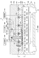
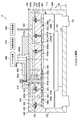
- FIG. 1 schematically shows a longitudinal sectional view of the apparatus.
- FIG. 1 shows a 2-OO′-2 cross section of FIG.
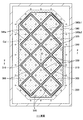
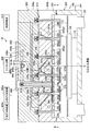
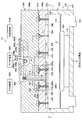
- FIG. 2 is a ceiling surface of the microwave plasma processing apparatus 10 and shows a cross section 1-1 of FIG.
- an upper gas shower plate is provided on the ceiling surface.
- the microwave plasma processing apparatus 10 includes a processing container 100 for plasma processing a glass substrate (hereinafter referred to as “substrate G”).
- the processing container 100 includes a container body 200 and a lid body 300.
- the container body 200 has a bottomed cubic shape with an upper portion opened, and the opening is closed by a lid 300.
- the lid body 300 includes an upper lid body 300a and a lower lid body 300b.
- An O-ring 205 is provided on a contact surface between the container main body 200 and the lower lid body 300b, whereby the container main body 200 and the lower lid body 300b are hermetically sealed to define a processing chamber.
- An O-ring 210 and an O-ring 215 are also provided on the contact surface between the upper lid body 300a and the lower lid body 300b, whereby the upper lid body 300a and the lower lid body 300b are sealed.
- the container body 200 and the lid body 300 are made of a metal such as an aluminum alloy, for example, and are electrically grounded.
- a susceptor 105 (stage) for placing the substrate G is provided.
- Susceptor 105 is made of, for example, aluminum nitride.
- the susceptor 105 is supported by a support 110, and a baffle plate 115 for controlling the gas flow in the processing chamber to a preferable state is provided around the susceptor 105.
- a gas exhaust pipe 120 is provided at the bottom of the processing container 100, and the gas in the processing container 100 is exhausted using a vacuum pump (not shown) provided outside the processing container 100.
- the dielectric plate 305, the metal electrode 310, and the metal cover 320 are regularly arranged on the ceiling surface of the processing vessel 100.
- a side cover 350 is provided around the metal electrode 310 and the metal cover 320.
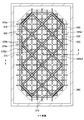
- the dielectric plate 305, the metal electrode 310, and the metal cover 320 are substantially square plates with slightly rounded corners. In addition, a rhombus may be sufficient.
- the metal electrode 310 refers to a flat plate provided adjacent to the dielectric plate 305 so that the dielectric plate 305 is substantially uniformly exposed from the outer edge of the metal electrode 310. As a result, the dielectric plate 305 is sandwiched between the inner wall of the lid 300 and the metal electrode 310.
- the metal electrode 310 is electrically connected to the inner wall of the processing container 100.
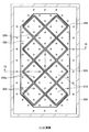
- the eight dielectric plates 305 and the metal electrodes 310 are arranged at an equal pitch at a position substantially inclined by 45 ° with respect to the substrate G and the processing container 100.
- the pitch is determined such that the diagonal length of one dielectric plate 305 is 0.9 times or more the distance between the centers of adjacent dielectric plates 305. Thereby, the slightly cut corners of the dielectric plate 305 are arranged adjacent to each other.
- the metal electrode 310 and the metal cover 320 are thicker than the metal cover 320 by the thickness of the dielectric plate 305. According to such a shape, the height of the ceiling surface becomes substantially equal, and at the same time, the portion where the dielectric plate 305 is exposed and the shape of the recesses in the vicinity thereof all have substantially the same pattern.
- the dielectric plate 305 is made of alumina, and the metal electrode 310, the metal cover 320, and the side cover 350 are made of an aluminum alloy.
- the eight dielectric plates 305 and the metal electrodes 310 are arranged in four rows in two rows.
- the present invention is not limited to this, and the increase in the number of the dielectric plates 305 and the metal electrodes 310 is also reduced. You can also.
- the dielectric plate 305 and the metal electrode 310 are equally supported by the lid 300 from four locations by screws 325 (see FIG. 2).
- the metal cover 320 and the side cover 350 are attached to the main body portion of the lid 300 with screws 325.
- a main gas flow path 330 formed in a lattice shape in a direction perpendicular to the paper surface is provided between the upper lid body 300a and the lower lid body 300b.
- the main gas flow path 330 divides the gas into a third gas flow path 325 a provided in the plurality of screws 325.
- a narrow tube 335 that narrows the flow path is fitted into the inlet of the third gas flow path 325a.
- the thin tube 335 is made of ceramics or metal.
- a first gas channel 310 a is provided between the metal electrode 310 and the dielectric plate 305.
- Second gas flow paths 320 a 1 and 320 a 2 are also provided between the metal cover 320 and the dielectric plate 305 and between the side cover 350 and the dielectric plate 305.
- the front end surface of the screw 325 is flush with the lower surfaces of the metal electrode 310, the metal cover 320, and the side cover 350 so as not to disturb the plasma distribution.
- the first gas discharge holes 345a opened in the metal electrode 310 and the second gas discharge holes 345b1 and 345b2 opened in the metal cover 320 and the side cover 350 are arranged at an equal pitch.
- the gas output from the gas supply source 905 passes from the main gas flow path 330 through the third gas flow path 325a (branch gas flow path), and the first gas flow path 310a and the metal cover 320 in the metal electrode 310.
- the first gas discharge hole 345a and the second gas discharge holes 345b1 and 345b2 are supplied to the processing chamber through the second gas flow paths 320a1 and 320a2 in the side cover 350.
- An O-ring 220 is provided on the contact surface between the lower lid 300 b and the dielectric plate 305 in the vicinity of the outer periphery of the first coaxial waveguide 610, and the atmosphere in the first coaxial waveguide 610 is placed inside the processing container 100. It is designed not to enter.
- the inner conductor 610a is inserted into the outer conductor 610b of the first coaxial waveguide formed by digging the lid 300.
- the inner conductors 620a to 640a of the second to fourth coaxial waveguides are inserted into the outer conductors 620b to 640b of the second to fourth coaxial waveguides formed by digging in the same manner, and the upper part thereof is the lid cover. It is covered with 660.
- the inner conductor of each coaxial tube is made of copper with good thermal conductivity.
- the surface of the dielectric plate 305 shown in FIG. 1 is a metal film 305a except for a portion where the microwave is incident on the dielectric plate 305 from the first coaxial waveguide 610 and a portion where the microwave is emitted from the dielectric plate 305. It is covered with. Accordingly, the propagation of the microwave is not disturbed by the gap generated between the dielectric plate 305 and the adjacent member, and the microwave can be stably guided into the processing container.
- the dielectric plate 305 is covered with the metal cover 320 and the inner wall of the processing vessel 100 in which the metal plate 310 and the dielectric plate 305 are not disposed one-on-one. (Including the inner wall of the processing container 100).
- the dielectric plate 305 and the inner wall of the processing vessel 100 in which the dielectric plate 305 is not disposed are substantially similar in shape or substantially The shape is symmetrical. According to such a configuration, the surface wave propagation part that propagates electromagnetic waves along the metal surface exposed inside the processing container 100 causes the metal plate side and the inner wall side (or the metal cover 320 and the side cover 350 side) from the dielectric plate 305. ) Can be supplied with microwave power almost evenly.
- the microwave emitted from the dielectric plate 305 propagates through the surfaces of the metal electrode 310, the metal cover 320, and the side cover 350 while distributing power in half as a surface wave.
- the surface wave propagating between the metal surface on the inner surface of the processing vessel and the plasma is hereinafter referred to as a conductor surface wave (metal surface wave).
- the conductor surface wave propagates to the entire ceiling surface, and uniform plasma is stably generated below the ceiling surface of the microwave plasma processing apparatus 10 according to the present embodiment.
- the side cover 350 is formed with an octagonal groove 340 so as to surround the entire eight dielectric plates 305, and the conductor surface wave propagating on the ceiling surface is prevented from propagating outside the groove 340. To do.
- a plurality of grooves 340 may be formed in multiple in parallel.
- a region having the center point of the adjacent metal cover 320 around the metal electrode 310 as a center is hereinafter referred to as a cell Cel (see FIG. 1).
- a cell Cel On the ceiling surface, a cell Cel is defined as a unit, and the configuration of the same pattern is regularly arranged in an 8-cell Cel.
- the refrigerant supply source 910 is connected to the refrigerant pipe 910a inside the lid, and the refrigerant supplied from the refrigerant supply source 910 circulates in the refrigerant pipe 910a inside the lid and returns to the refrigerant supply source 910 again.
- the processing container 100 is kept at a desired temperature.
- a refrigerant pipe 910b passes through the inner conductor 640a of the fourth coaxial waveguide in the longitudinal direction. Heating of the internal conductor 640a is suppressed by passing the coolant through this flow path.
- FIG. 3 is a 3-3 cross section of FIG.
- the gas supplied from the gas supply source 905 flows to the main gas flow path 330.
- the main gas flow path 330 is formed using a space between the upper lid body 300a and the lower lid body 300b. That is, the main gas channel 330 is provided in the front-rear direction of the paper surface of FIG. As a result, the boundary portion between the upper lid body 300a and the lower lid body 300b becomes a gas flow path having a lattice shape on one side.
- the main gas flow path 330 divides the gas into gas flow paths (hereinafter referred to as third gas flow paths 325a) provided in the plurality of screws 325. This is part of the branch gas flow path.
- a narrow tube 335 that narrows the flow path is fitted into the inlet of the third gas flow path 325a.
- the thin tube 335 is made of ceramics or metal.
- the third gas flow path 325a communicates with a horizontal hole (referred to as a fourth gas flow path 325a1) formed in the side surface of the screw 325.
- the gas that has passed through the fourth gas flow path 325a1 passes through the gap between the wave washer 355a and the spacer 355b and the screw 325, and the gap (first gap) formed between the metal electrode 310 and the dielectric plate 305. (Referred to as gas flow path 310a).
- the first gas flow path 310a is formed by digging the upper surface of the metal electrode 310.
- a plurality of first gas discharge holes 345a are opened at an equal pitch on the lower surface of the metal electrode 310.
- the gas introduced into the first gas flow path 310a is discharged into the processing container from the plurality of first gas discharge holes 345a.
- the gas flow paths of the metal cover 320 and the side cover 350 are the same as those of the metal electrode 310. That is, the gas that has passed through the fourth gas flow path 325a1 has a gap formed between the metal cover 320 and the dielectric plate 305, and a gap formed between the side cover 350 and the dielectric plate 305 ( It is led to the second gas flow path 320a1, 320a2).
- a plurality of second gas discharge holes 345b1 and 345b2 are opened at equal pitches on the lower surfaces of the metal cover 320 and the side cover 350.
- the gas introduced into the second gas flow paths 320a1 and 320a2 is discharged into the processing container from the plurality of second gas discharge holes 345b1 and 345b2.
- a plurality of branch gas flow paths are connected to the downstream side of the main gas flow path 330, and further, a plurality of first gas discharge holes 345a and second gas flow paths are connected to the downstream side. Gas discharge holes 345b1 and 345b2 are provided.
- the metal electrode 310 and the metal cover 320 are thicker than the metal cover 320 by the thickness of the dielectric plate 305. Therefore, if the depths of the first gas flow path 310a and the second gas flow paths 320a1 and 320a2 are equal, the lengths of the second gas discharge holes 345b1 and 345b2 are larger than the length of the first gas discharge hole 345a. Also gets longer.
- the second gas discharge holes 345b1 and 345b2 are thick at the top and thin at the bottom. The thickness and length of the narrowed portion of the lower part of the second gas discharge holes 345b1 and 345b2 are equal to the thickness and length of the first gas discharge hole 345a.
- a wave washer 355a and a spacer 355b are provided between the lid 300 and the metal electrode 310 in a state where they are arranged vertically.
- the wave washer 355a is made of a metal such as stainless steel (SUS) or an aluminum alloy.
- the spacer 355b is made of a metal such as an aluminum alloy.
- a wave washer 355a is provided between the lid 300 and the metal electrode 310 so that the lid 300 and the metal electrode 310 are securely and electrically connected even when both surfaces of the dielectric plate 305 are in close contact with the metal portion.
- the wave washer 355a may be any elastic material such as a disc spring, a spring washer, and a metal spring.
- the metal electrode 310 can be lifted through the screw 325 with an appropriate force at all times (a force slightly larger than the force for crushing the O-ring 220 to bring the dielectric plate 305 and the lower lid 300b into close contact).
- a wave washer 430b having an optimal spring force is inserted between the nut 435 and the lower lid 300b. When the nut 435 is tightened, the deformation amount is constant without being tightened until the wave washer 430b becomes flat.
- any elastic material such as a disc spring, a spring washer, and a metal spring may be used.
- a washer 430a is provided between the nut 435 and the wave washer 430b, but it may or may not be present. Further, a washer 430c is provided between the wave washer 430b and the lower lid 300b. Normally, there is a gap between the screw 325 and the lid 300, and the gas in the main gas flow path 330 flows to the first gas flow path 310a through this gap. When this uncontrolled gas flow rate is large, there is a problem that the gas discharge from the first gas discharge hole 345a becomes non-uniform. For this reason, the gap between the washer 430c and the screw 325 is reduced, and the thickness of the washer 430c is increased to suppress the flow rate of the gas flowing through the outside of the screw 325.
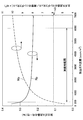
- Fig. 5 shows the calculation result of the in-plane uniformity of the gas flow rate discharged from the shower plate.
- the horizontal axis represents the gas flow rate per unit area supplied into the processing container 100.
- the solid line Rp is the uniformity of the discharge gas flow rate, that is, the ratio of the discharge gas flow rate at both ends of the main gas flow channel 330 when the gas is introduced from the gas supply source 905 to one end of the main gas flow channel 330. Is the ratio of gas conductance between the main gas flow path 330 and the narrow tube 335.
- the width of the main gas flow path 330 is 20 mm
- the height is 6 mm
- the inner diameter of the narrow tube 335 is 0.5 mm
- the length is 12 mm
- the diameter of the first gas discharge hole 345a is 0.6 mm
- the length is 5 mm.
- FIG. 5 shows that the gas conductance ratio between the main gas flow path 330 and the narrow tube 335 increases as the discharge gas flow rate increases. This is due to the following reason.
- the gas conductance of the cylinder is proportional to the cube of the diameter in the molecular flow region where the pressure is low, and is independent of the pressure. On the other hand, in a viscous flow region where the pressure is high, it is proportional to the fourth power of the diameter, and further proportional to the pressure.
- the pressure of the gas flow path becomes high. If both the main gas flow path 330 and the narrow tube 335 are in a viscous flow region, their gas conductance is proportional to the pressure, so that the gas conductance ratio is constant with respect to the discharge gas flow rate. On the other hand, when the discharge gas flow rate is decreased, the narrow tube 335 having a smaller diameter first becomes a molecular flow region, and the gas conductance becomes independent of pressure, so that the gas conductance ratio becomes smaller.
- the gas conductance ratio between the main gas flow path 330 and the narrow tube 335 is 59000.
- the uniformity of the discharge gas flow rate at this time is 0.3%, and it can be seen that excellent uniformity is obtained.
- the uniformity is further improved with increasing discharge gas flow rate. This is because the gas conductance ratio between the main gas flow path 330 and the narrow tube 335 increases.
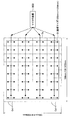
- the metal electrode 310 is provided with a total of 64 first gas discharge holes 345a in 8 rows ⁇ 8 rows. All of these gas discharge holes communicate with the first gas flow path 310a.
- the gas that has passed through the four narrow tubes 335 flows into the first gas flow path 310a. Accordingly, gas is supplied to 16 (64/4) first gas discharge holes 345a per one thin tube 335.
- the metal cover 320 Regarding the side cover 350, the number of gas discharge holes supplied by the narrow tube 335 is different.
- the values of Cr / N are equal for all the thin tubes 335. That is, the gas is uniformly discharged from all the gas discharge holes. This makes it possible to perform uniform processing on the substrate G.
- the Cr / N values the same, for the metal electrode 310 and the metal cover 320, the diameter and length of the narrow tube 335 are made equal to make the gas conductance equal.
- the diameter of the narrow tube 335 is kept constant, and the length is adjusted so that the gas conductance Cr becomes a desired value.
- the gas conductance of the narrow tube 335 is set smaller than the sum of the gas conductances of the 16 first gas discharge holes 345a supplied per thin tube 335.
- (the gas conductance of the thin tube 335) / (the sum of the gas conductances of the first gas discharge holes 345a) is 1 / 36.4 to 1/1 at the assumed gas flow rate of 300 to 6000 sccm / m 2. 14.5.
- the flow velocity of the gas discharged from the first gas discharge hole 345a is 90 m / s at the maximum, which is much smaller than the sound speed of 360 m / s.
- the gas conductance of the main gas channel 330 In order to discharge gas uniformly over the front surface of the substrate G, the gas conductance of the main gas channel 330 must be sufficiently larger than the gas conductance of the branch gas channel.
- the diameter of the gas discharge hole is reduced in order to keep the gas conductance of the branch gas flow path small.
- this method is technically difficult because a large number of small-diameter holes must be formed with very high accuracy.
- the pitch of the gas discharge holes must be increased, uneven plasma processing may occur.
- the gas ejection flow rate reaches the sonic velocity, the gas flow in the processing container is disturbed, and good processing cannot be performed, and an unnecessary film may be deposited on the inner surface of the processing container.
- the conductance is limited by providing a constriction (narrow tube 335) in a part of the upstream side of the branch gas flow path instead of the gas discharge hole. That is, the function of releasing gas and the function of limiting conductance are separated. As described above, only the narrow tube 335 is used so that (the gas conductance of the narrow tube 335) / (the sum of the gas conductances of the first gas discharge holes 345a) is sufficiently smaller than 1 (1 / 14.5 or less). The conductance is effectively limited. Thereby, even if the conductance changes somewhat downstream of the narrow tube 335, uniformity is maintained. Further, the gas conductance ratio between the main gas flow path 330 and the narrow tube 335 is set sufficiently larger than 1 (59000 or more in the present embodiment) so that high uniformity can be obtained.
- the pressure of the gas flow path on the downstream side can be kept low by disposing the throttle part (the narrow tube 335) in the upstream part of the branch gas flow path.
- the flow rate of the gas leaking from the downstream gas flow path into the processing container 100 through the gap without passing through the gas discharge hole can be kept low, so that the gas can be discharged more uniformly.
- the exposed area of the dielectric plate 305 disposed on the ceiling surface is large, electrons are attracted to the dielectric plate 305 by the electric field in the sheath, and the surface of the dielectric plate 305 is negative. Is biased to etch the surface of the dielectric plate 305, or the ion energy assists to promote a chemical reaction on the surface of the dielectric plate 305.
- the reaction product is treated by the reducing action of hydrogen radicals. It accumulates on the inner surface of the container and causes contamination and particles.
- the upper gas shower plate by providing a plurality of gas discharge holes in the metal electrode 310 and the metal cover 320, the etching of the surface of the dielectric plate 305 is suppressed and the inner surface of the processing vessel is moved. It is possible to suppress the accumulation of reaction products, and to reduce contamination and particles. Further, since the upper gas shower head is made of metal, it can be easily processed and the cost can be greatly reduced.
- the thin tube 335 is an example of a throttle portion that is provided in a plurality of branch gas passages and narrows the gas passages of the branch gas passages.
- Other examples of the throttle portion include a narrow hole, an orifice, a valve body, a porous member, and the like.
- the restricting portion may be provided at a position closer to the main gas flow path 330 than the plurality of first gas discharge holes 345a and the second gas discharge holes 345b. It may be provided inside the branch gas channel (screw 325) or between the main gas channel 330 and the plurality of branch gas channels.
- the first gas flow path 310a may be a groove formed on the surface of the dielectric plate 305 adjacent to the metal electrode 310.
- the second gas flow path 320 a may be a groove formed on a surface of the lid 300 adjacent to the metal cover 320 or the side cover 350.
- FIG. 4E A modification of the first embodiment is shown in FIG. Below, it demonstrates centering on a different point from 1st Embodiment, and abbreviate
- a fifth gas flow path 325c is provided between the screw 325 and the lower lid body 300b.
- a gas flow path is not provided inside the screw 325.
- the gas introduced into the main gas flow path flows through the fifth gas flow path 325c through the narrow hole 360 (throttle portion) provided in the washer 430c, as shown in an enlarged view in FIG. 4E.
- the plurality of first gas discharge holes 345a and the plurality of second gas discharge holes 345b1 and 345b2 are guided from the one gas flow path 310a and the second gas flow paths 320a1 and 320a2.
- the front end surface of the screw 325 is not flush with the lower surfaces of the metal electrode 310, the metal cover 320, and the side cover 350, and is easy to manufacture.
- the first gas flow path 310 a is provided inside the metal electrode 310.
- the metal electrode 310 can form the 1st gas flow path 310a inside by combining two aluminum plates and joining by welding.
- second gas flow paths 320a1 and 320a2 are provided inside the metal cover 320 or the side cover 350, respectively.
- the first to third gas flow paths 310a, 320a, and 325a are part of the branch gas flow paths.
- FIG. 7 shows a 5-OO′-5 cross section of FIG.
- FIG. 8 shows a 4-4 cross section of FIG.
- a lower gas nozzle is provided in addition to the upper gas shower plate.
- the present embodiment two types of main gas flow paths are provided at the boundary between the upper lid body 300a and the lower lid body 300b.
- One is a first main gas flow path 330a formed on the upper surface of the lower lid 300b.
- the other is a second main gas flow path 330b formed inside the lower lid 300b.
- the second main gas flow path 330b is a groove provided on the upper surface of the lower lid 300b, which is covered with an aluminum alloy plate, but may be a long hole provided in the lower lid 300b. Good.
- the first main gas flow path 330a is a flow path for supplying gas to the lower gas nozzle 370, and for example, a processing gas for film formation or etching is supplied.
- the second main gas flow path 330b is a flow path for supplying gas to the upper gas shower plate.
- a plasma excitation gas such as a rare gas is supplied from the upper gas supply source 905a.
- the upper gas supply source 905a corresponds to a first gas supply source that supplies a first gas including a plasma excitation gas.
- the plasma excitation gas is emitted from the upper part where the electron temperature is high, and the lower electron temperature is lowered from the lower gas supply source 905b (corresponding to the second gas supply source).
- the lower gas supply source 905b corresponds to a second gas supply source that supplies a desired second gas.
- a fifth gas flow path 325c is provided between the screw 325 and the lower lid 300b.
- a sixth gas channel 365 is provided between the second main gas channel 330b and the fifth gas channel 325c.
- the sixth gas flow path 365 connects the second main gas flow path 330b and the fifth gas flow path 325c while being inclined obliquely toward the substrate side. As a result, the gas passes through the second main gas flow path 330b and is guided from the sixth gas flow path 365 to the fifth gas flow path 325c.
- the gas that has passed through the fifth gas flow path 325c is guided to the first gas flow path 310a and the second gas flow paths 320a1 and 320a2, and the first gas discharge holes 345a and the second gas flow holes 345a provided in the upper shower plate are provided.
- the second gas discharge holes 345b1 and 345b2 are discharged to the substrate G side.
- the first gas discharge hole 345a and the second gas discharge holes 345b1 and 345b2 are the first gas supplied from the first gas supply source, which is the first space adjacent to the lower surface of the lid, which is the internal space of the processing container. It is an example of the 1st gas discharge
- a narrow tube 335a that narrows the second main gas channel 325a and a narrow tube 335b that narrows the sixth gas channel 365 are provided.
- the gas conductance of the second main gas channel 325 a and the sixth gas channel 365 is significantly smaller than the gas conductance of the main gas channel 330.
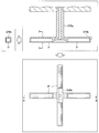
- the lower gas nozzle 370 is provided in the space between the ceiling surface of the lid 300 and the substrate G.
- the screw 325 penetrates the dielectric plate 305 and the metal electrode 310 and is connected to the first gas pipe 370a.
- the first gas pipes 370a are arranged on the ceiling surface at an equal pitch.
- four second gas pipes 370b are connected to the tip of the first gas pipe 370a in a cross shape.
- the second gas pipe 370b is arranged substantially equiangularly with the first gas pipe 370a as the center, substantially perpendicular to the first gas pipe 370a.
- a plurality of fourth gas discharge holes 370b1 are provided on the substrate G side surface of the branch gas flow path (second gas pipe 370b).
- the gas introduced into the first main gas flow path 330a passes through the flow paths in the narrow tube 335a, the third gas discharge hole 345c, the first gas pipe 370a, and the second gas pipe 370b, and reaches the fourth. From the gas discharge hole 370b1 to the substrate G side.
- Fourth gas discharge hole 370b1 is provided on the substrate G side surface of the branch gas flow path (second gas pipe 370b).
- the lower gas nozzle 370 is made of an aluminum alloy having an alumina protective film on the surface. Further, as shown in FIG. 8, the lower gas nozzle 370 on the outer peripheral portion may include only one or two second gas pipes 370 b. In the present embodiment, the screw 325 and the first gas pipe 370a, and the first gas pipe 370a and the second gas pipe 370b are integrally formed, but may be separable. . The number of the second gas pipes connected to the first gas pipe 370a may not be four, or may not be connected vertically to the first gas pipe 370a.
- the flow rate of the gas discharged from the gas discharge hole is reduced by providing the throttle portion upstream of the branch gas flow path.
- the gas can be uniformly introduced onto the large area substrate while being suppressed. As a result, uniform and high-quality plasma processing can be performed.
- the lower gas nozzle 370 there is no fear of bending due to thermal expansion as compared with a conventional shower head in which pipe-like gas pipes are integrally formed in a lattice shape. Further, since the lower gas nozzle 370 is made of metal, there is no problem of rigidity with respect to the shower head formed of the conventional dielectric plate 305, and it can be used for a large substrate. Moreover, it is possible to prevent abnormal discharge from occurring inside the gas pipe.
- a part of the second gas pipe 370b may be formed of a porous body P as shown in FIG. 9 is a cross section of the lower gas nozzle 370 (cross section 6-6 in the lower view of FIG. 9), the lower view of FIG. 9 is the lower surface of the lower gas nozzle 370, and the left side of FIG. 9 is a cross section of the second gas pipe 370b. (7-7 cross section in the upper view of FIG. 9) is shown.
- the porous body P is made of a metal such as aluminum or a ceramic such as alumina.
- the gas is discharged into the processing chamber through the first gas pipe 370a and between the pores of the porous body P of the second gas pipe 370b. Therefore, the gas flow rate can be sufficiently reduced and released into the processing chamber.
- a single or a plurality of slit-shaped openings may be formed in the second gas pipe 370b, and gas may be introduced into the processing chamber from the slit-shaped openings formed in a cross shape.
- FIG. 10 shows a cross section taken along line 9-0-0'-9 of FIG.
- FIG. 11 shows an 8-8 cross section of FIG.
- the shape of the lower gas nozzle 370 is different from that of the lower gas nozzle 370 according to the second embodiment.
- each of the plurality of lower gas nozzles 370 includes four third gas pipes 370c.
- the third gas pipe 370c is made of ceramics such as alumina, glass such as quartz, or metal such as aluminum alloy.
- the four third gas pipes 370c are fixed to the screw 325 by welding, bonding, press-fitting, screwing, or the like.
- the four third gas pipes 370c are arranged at substantially equal angles around the plurality of branch gas flow paths (screws 325).
- Each third gas pipe 370c has a pipe shape.
- a fourth gas discharge hole 370c1 is provided at the tip of the third gas pipe 370c.
- the gas introduced into the first main gas flow path 330a passes through the narrow tube 335a, the third gas discharge hole 345c, and the third gas tube 370c, and is discharged from the fourth gas discharge hole 370c1 to the substrate G side. Is done.
- the fourth gas discharge hole 370b1 and the fourth gas discharge hole 370c1 are spaces in the processing container, and are formed in the second space between the first space and the space for storing the substrate.
- a plurality of fourth gas discharge holes 370c1 are provided at equal intervals on the same plane that is opposite to the substrate G and parallel to the substrate G.
- the substrate G can be uniformly processed.
- the outer shape of the third gas pipe 370c is thin, plasma diffusion is not hindered so much. For this reason, high-speed processing can be performed.
- the lower gas nozzle 370 is composed of a pipe-shaped third gas pipe 370c, the cost is low, the structure is simple, and maintenance is easy.
- some of the lower gas nozzles 370 on the outer peripheral portion include only one or two third gas pipes 370c.
- the screw 325 and the third gas pipe 370c are directly connected, but the connecting portion of the third gas pipe 370c may be separable from the screw 325.
- the number of the third gas pipes 370c connected to the screw 325 may not be four, or may be connected vertically.
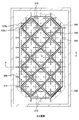
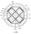
- FIG. 12 shows a cross section taken along the line 11-OO′-11 of FIG.
- FIG. 13 shows a 10-10 cross section of FIG.
- FIG. 14 is a cross section taken along line 12-12 of FIG.
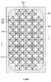
- the microwave plasma processing apparatus 10 is for a circular substrate (for example, a semiconductor substrate), and is provided only with an upper gas shower plate.
- the gas flow paths in the metal electrode 310, the metal cover 320, and the side cover 350 are formed by grooves formed on the upper surface of each member.
- the third gas channel 325a is formed inside the screw 325.
- the number of cells is four, and the first gas discharge holes 345a and the second gas discharge holes 345b1 and 345b2 are equally arranged at an equal pitch.
- the microwave is supplied from the microwave source 900, transmitted from the transmission line 900a to the coaxial tube 900b, and transmitted from the branch plate 900c to the first coaxial tube 610.
- Each coaxial tube is disposed inside the lid cover 660.
- the gas supplied from the gas supply source 905 flows to the main gas flow path 330 as shown in FIG.
- the main gas flow path 330 is an octagonal space provided between the upper lid body 300a and the lower lid body 300b. As a result, one surface of the boundary portion between the upper lid body 300a and the lower lid body 300b becomes a gas flow path.
- the main gas flow path 330 divides the gas into the third gas flow path 325a provided in the plurality of screws 325.
- a narrow tube 335 that narrows the flow path is fitted into the inlet of the third gas flow path 325a.
- the gas flow rate discharged from the gas discharge hole in the peripheral part of the processing container 100 is the gas discharged from the gas discharge hole in the central part. It is designed to be greater than the flow rate. That is, when Cr is the gas conductance of the narrow tube 335 and N is the number of gas holes supplied per thin tube 335, the value of Cr / N is larger in the narrow tube 335 closer to the outer periphery. Thereby, even the small processing container 100 can perform uniform processing on the substrate G.
- the inner diameter of the narrow tube 335 is unified to 0.4 mm, and the gas conductance is adjusted by changing the length. Further, the gas conductance may be adjusted by changing the inner diameter of the narrow tube 335.
- two grooves 340a and 340b for suppressing propagation of conductor surface waves are provided.
- a plurality of grooves having different sizes and aspect ratios it is possible to deal with a wider range of electron density.
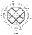
- FIG. 15 is a cross-sectional view taken along line 14-0-0′-14 of FIG.
- FIG. 16 shows a 13-13 cross section of FIG.
- the microwave plasma processing apparatus 10 according to the fifth embodiment is for a circular substrate (for example, a semiconductor substrate) as in the fourth embodiment, but is provided with a lower gas shower plate 410 in addition to the upper gas shower plate. This is different from the fourth embodiment in which only the upper gas shower plate is provided.
- the number of cells is also four in this case, and the first gas discharge holes 345a and the second gas discharge holes 345b1 and 345b2 are equally arranged at an equal pitch.
- the microwave is supplied from the microwave source 900 and transmitted from the transmission line 900 a to the fourth coaxial waveguide 640.
- the fourth coaxial waveguide 640 is T-branched to the third coaxial waveguide 630 (rod 630a1 and internal conductor connecting plate 630a2), and the third coaxial waveguide 630 is the fifth coaxial waveguide 650. T-branch to
- the first gas flow path 310a and the second gas flow paths 320a1 and 320a2 in the metal electrode 310, the metal cover 320, and the side cover 350 are formed by grooves formed on the upper surface of each member.
- a third gas flow path 325 a is formed inside the screw 325.
- the lower gas shower plate 410 is formed integrally with the processing container 100 in a mesh shape.
- the plasma excitation gas is supplied from the upper gas shower plate into the processing container.
- the processing gas is supplied below the position where the plasma excitation gas is supplied from the lower gas shower plate 410. Thereby, desired plasma can be generated and good plasma treatment can be performed on the substrate.
- the lower gas nozzle 370 and the lower gas shower plate 410 are an example of a lower gas discharge member that discharges the gas that has passed through the plurality of branch gas flow paths into the space between the lid 300 and the substrate G.
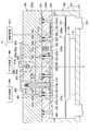
- FIG. 17 shows a 16-O—O′-16 cross section of FIG.
- FIG. 18 shows a section 15-15 in FIG.
- This embodiment is different from the above-described embodiments in that the metal cover 320 and the side cover 350 are not provided. Further, in the present embodiment, there is no diaphragm portion.
- the metal cover 320 and the side cover 350 are not provided on the right side of the center line O shown in FIG. 17, and the lower lid 300b is exposed on the ceiling surface.
- a plurality of gas discharge holes (referred to as fifth gas discharge holes 345d) are provided directly on the lower surface of the lower lid 300b.
- the lower part of the fifth gas discharge hole 345d is thinner than the other part.
- a wide main gas flow path 330 communicating with the plurality of second gas discharge holes 345b is installed at a boundary portion between the upper lid 300a and the lower lid 300b.
- a third gas flow path 325 a is provided inside the plurality of screws 325.
- a third gas discharge hole 345c narrower than the third gas flow path 325a is formed at the tip of the third gas flow path 325a.
- the gas passes through the gas flow path of the main gas flow path 330 and is introduced into the processing container from the plurality of third gas discharge holes 345c through the third gas flow path 325a.
- the gas passes from the fourth gas flow path 325a1 provided on the side surface of the screw 325 above the third gas discharge hole 345c to the first gas flow path 310a provided on the upper surface of the metal electrode 310.
- the plurality of first gas discharge holes 345a are guided. Of the four screws 325 for fixing the metal electrode, only one of the four screws 325a1 is provided, and the other three are not provided.
- the first gas discharge hole 345a, the fifth gas discharge hole 345d, and the third gas discharge hole 345c are arranged at an equal pitch.
- the gas conductance of the first gas channel 310a and the first gas discharge hole 345a is set sufficiently larger than the gas conductance of the fourth gas channel 325a1.
- the narrow hole under the fifth gas discharge hole 345d, the third gas discharge hole 345c, and the fourth gas flow path 325a1 have substantially the same diameter and length, and the gas conductance is equal. Yes. Thereby, gas can be uniformly emitted from the entire ceiling surface.
- the dielectric 305 is not covered with a metal film. As described above, when the dielectric 305 is not covered with the metal film, the dielectric 305 is provided in the metal electrode 310 so as not to discharge in the groove (first gas flow path 310a) provided in the metal electrode 310.
- the depth of the groove formed is preferably 0.2 mm or less. The reason will be explained.
- the gas flow path loses energy by colliding with the wall before the energy required for ionization is obtained from the microwave electric field by narrowing the interval. It becomes difficult to discharge.
- the depth of the gas flow path should be set to such a size that does not discharge even in the situation where discharge is most likely under actual use conditions.
- ua is the average velocity of electrons
- ⁇ c is the collision frequency of electrons.
- k is a Boltzmann constant
- T is an electron temperature
- the microwave frequency 915 MHz
- the mean free path at this time is calculated from the above equation, it is 0.20 mm. That is, if the depth of the gas channel is 0.2 mm or less, stable plasma can always be excited without discharging in the gas channel.
- the gas discharge holes 345a and 345c are formed in the metal electrode 310, and a plurality of gas discharge holes 345d are also formed directly in the metal lid 300.
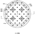
- FIG. 19 shows a cross section taken along line 18-O′-18 of FIG.
- FIG. 20 shows a 17-17 cross section of FIG.
- the gas passes through the main gas flow path 330 and is introduced into the processing container from the plurality of third gas discharge holes 345c via the third gas flow path 325a.
- the plurality of third gas discharge holes 345c are evenly arranged on the ceiling surface.
- the lower part of the third gas discharge hole 345c is thinner than the other part of the third gas discharge hole 345c and the third gas flow path 325a. Thereby, gas can be uniformly emitted from the entire ceiling surface.
- the metal electrode 310, the metal cover 320, and the side cover 350 are not provided with gas discharge holes.
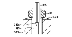
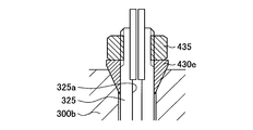
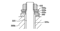
- a nut 435 is attached to the outer periphery of the screw 325 protruding into the main gas flow path 330.
- An O-ring 225 is provided on the side contact surface between the lower lid 300b and the screw 325 to seal the gap between the lower lid 300b and the screw 325. This prevents gas from leaking around the screw 325.
- the O-ring 225 may be disposed at a position in contact with the washer 430c.
- An elastic member such as a wave washer and a disc spring may be used together with the O-ring 225.
- a seal washer may be used in place of the O-ring 225 for sealing.
- a disc spring 430d may be used as shown in FIG. 4B. Since the disc spring 430d has a strong spring force, it can generate a force sufficient to crush the O-ring 220. Since the upper and lower corners of the disc spring 430d are in close contact with the nut 435 and the lower lid 300b, gas leakage can be suppressed.
- the material of the disc spring is Ni-plated SUS or the like.
- gas leakage may be prevented by using a taper washer 430e.
- the taper washer 430e and the lower lid body 300b are in contact with each other in an oblique direction. And the lower lid 300b can be reliably sealed.
- the screw 325 is fixed to the lower lid 300b by the taper washer 430e, the screw 325 does not rotate together with the nut 435 when the nut 435 is tightened. For this reason, there is no possibility that the screw 325 and the metal electrode 310 and the like are slid and the surface is damaged, and the protective film formed on the surface is not peeled off.
- the material of the taper washer 430e is preferably metal or resin.
- the screw 325 in order to prevent the screw 325 from rotating, the screw 325 may be fixed to the metal electrode 310 or the like by press-fitting, shrink fitting, welding, adhesion, or the like, or the screw 325 may be fixed to the metal electrode. You may form integrally with 310 grade
- the gas supply can be well controlled by providing the upper gas shower plate, the lower gas nozzle, or the lower gas shower plate.
- the gas supply can be well controlled by providing the upper gas shower plate, the lower gas nozzle, or the lower gas shower plate.
- the metal electrode 310, the metal lid 300, the metal cover 320, and the side cover 350 it is possible to suppress the etching of the surface of the dielectric plate that has conventionally occurred and to the inner surface of the processing vessel. Accumulation of reaction products can be suppressed, and contamination and particles can be reduced.
- the first gas discharge hole 345 a of the metal electrode 310, the metal cover 320, the second gas discharge holes 345 b 1 and 345 b 2 of the side cover 350, and the fifth gas discharge hole 345 d of the cover body 300 are the substrate of the cover body 300. You may be located in the convex part formed in the surface of the side. This is to prevent the occurrence of abnormal discharge in the vicinity of the gas discharge hole provided in the convex portion by utilizing the fact that plasma is hardly generated in the convex portion.
- the plasma processing apparatus may be an apparatus having only the lower gas nozzle 370 shown in FIGS. 7 and 10 without the upper gas shower head.
- the plurality of types of upper gas shower heads and lower gas nozzles 370 disclosed in the embodiments can be arbitrarily combined.
- a conventional lower gas nozzle 370 may be added to the upper gas shower head having the throttle portion shown in FIGS.
- the lower gas nozzle 370 can also be formed from ceramics.
- the microwave source 900 that outputs a 915 MHz microwave is described, but a microwave source that outputs a microwave such as 896 MHz, 922 MHz, and 2.45 GHz may be used.
- the microwave source is an example of an electromagnetic wave source that generates an electromagnetic wave for exciting plasma, and includes a magnetron and a high-frequency power source as long as the electromagnetic wave source outputs an electromagnetic wave of 100 MHz or higher.
- the shape of the metal electrode 310 is not limited to a quadrangular shape, and may be a triangular shape, a hexagonal shape, or an octagonal shape.
- the shape of the dielectric plate 305 and the metal cover 320 is the same as the shape of the metal electrode 310.
- the metal cover 320 may or may not be provided, but if the metal cover 320 is not provided, the gas flow path may be formed directly in the lid 300.
- the microwave plasma processing apparatus can execute various processes for finely processing an object to be processed by plasma, such as a film forming process, a diffusion process, an etching process, an ashing process, and a plasma doping process.
- the plasma processing apparatus can process a large-area glass substrate, a circular silicon wafer, and a square SOI (Silicon On Insulator) substrate.
- a large-area glass substrate a circular silicon wafer, and a square SOI (Silicon On Insulator) substrate.
- the plasma processing apparatus is not limited to the above-described microwave plasma processing apparatus.
- a radial line slot antenna (RLSA) a CMEP (Cellular Microwave Exclusion Plasma) plasma processing apparatus, and an ICP (InductivePulsePulse). It can be used for apparatuses such as a plasma processing apparatus, a capacitively coupled plasma processing apparatus, and an ECR (Electron Cyclotron Resonance).
- the CMEP plasma processing apparatus is an apparatus that emits microwaves transmitted through a waveguide into a processing container from a plurality of dielectric plates, and generates plasma by microwave energy. For example, it is described in JP2007-273636A.
- the upper gas shower plate or the lower gas nozzle according to the present invention can be used in a plasma processing apparatus for solar cells having a substrate size of 1352 mm ⁇ 1206 mm as shown in FIG.
- the microwave output from the microwave source propagates through the branch circuit, is supplied to the cell Cel while distributing power, and the conductor surface wave propagates through the metal surface of the ceiling.
- the plasma excitation area Ea is designed to be larger than the size of the substrate G in order to uniformly plasma process the substrate.
Landscapes
- Physics & Mathematics (AREA)
- Engineering & Computer Science (AREA)
- Plasma & Fusion (AREA)
- Chemical & Material Sciences (AREA)
- Analytical Chemistry (AREA)
- Plasma Technology (AREA)
- Drying Of Semiconductors (AREA)
- Chemical Vapour Deposition (AREA)
Priority Applications (3)
| Application Number | Priority Date | Filing Date | Title |
|---|---|---|---|
| KR1020107024030A KR101202270B1 (ko) | 2008-06-11 | 2009-06-03 | 플라즈마 처리 장치 및 플라즈마 처리 방법 |
| US12/997,211 US9196460B2 (en) | 2008-06-11 | 2009-06-03 | Plasma processing apparatus and plasma processing method |
| CN2009801214626A CN102057465A (zh) | 2008-06-11 | 2009-06-03 | 等离子体处理装置及等离子体处理方法 |
Applications Claiming Priority (2)
| Application Number | Priority Date | Filing Date | Title |
|---|---|---|---|
| JP2008-153379 | 2008-06-11 | ||
| JP2008153379A JP5520455B2 (ja) | 2008-06-11 | 2008-06-11 | プラズマ処理装置 |
Publications (1)
| Publication Number | Publication Date |
|---|---|
| WO2009150979A1 true WO2009150979A1 (ja) | 2009-12-17 |
Family
ID=41416688
Family Applications (1)
| Application Number | Title | Priority Date | Filing Date |
|---|---|---|---|
| PCT/JP2009/060159 Ceased WO2009150979A1 (ja) | 2008-06-11 | 2009-06-03 | プラズマ処理装置及びプラズマ処理方法 |
Country Status (6)
| Country | Link |
|---|---|
| US (1) | US9196460B2 (enExample) |
| JP (1) | JP5520455B2 (enExample) |
| KR (1) | KR101202270B1 (enExample) |
| CN (2) | CN102760633B (enExample) |
| TW (1) | TW201015653A (enExample) |
| WO (1) | WO2009150979A1 (enExample) |
Cited By (1)
| Publication number | Priority date | Publication date | Assignee | Title |
|---|---|---|---|---|
| US9267205B1 (en) * | 2012-05-30 | 2016-02-23 | Alta Devices, Inc. | Fastener system for supporting a liner plate in a gas showerhead reactor |
Families Citing this family (29)
| Publication number | Priority date | Publication date | Assignee | Title |
|---|---|---|---|---|
| JP5520455B2 (ja) * | 2008-06-11 | 2014-06-11 | 東京エレクトロン株式会社 | プラズマ処理装置 |
| JP5478058B2 (ja) * | 2008-12-09 | 2014-04-23 | 国立大学法人東北大学 | プラズマ処理装置 |
| KR101327458B1 (ko) * | 2012-01-10 | 2013-11-08 | 주식회사 유진테크 | 냉각 방식의 샤워헤드 및 이를 구비하는 기판 처리 장치 |
| KR101206836B1 (ko) * | 2012-03-14 | 2012-11-30 | 한국델파이주식회사 | 스티어링 기어의 랙 바 지지 장치 |
| JP2014096553A (ja) * | 2012-10-09 | 2014-05-22 | Tokyo Electron Ltd | プラズマ処理方法、及びプラズマ処理装置 |
| JP2014082354A (ja) * | 2012-10-17 | 2014-05-08 | Hitachi High-Technologies Corp | プラズマ処理装置 |
| JP5700032B2 (ja) * | 2012-12-26 | 2015-04-15 | 東京エレクトロン株式会社 | プラズマドーピング装置、およびプラズマドーピング方法 |
| JP6137986B2 (ja) * | 2013-08-07 | 2017-05-31 | 株式会社荏原製作所 | 基板洗浄及び乾燥装置 |
| US9336997B2 (en) * | 2014-03-17 | 2016-05-10 | Applied Materials, Inc. | RF multi-feed structure to improve plasma uniformity |
| JP6378360B2 (ja) * | 2014-11-26 | 2018-08-22 | 株式会社日立ハイテクノロジーズ | イオンビーム装置 |
| JP6404111B2 (ja) * | 2014-12-18 | 2018-10-10 | 東京エレクトロン株式会社 | プラズマ処理装置 |
| DE102015101461A1 (de) | 2015-02-02 | 2016-08-04 | Aixtron Se | Vorrichtung zum Beschichten eines großflächigen Substrats |
| WO2018042877A1 (ja) * | 2016-09-05 | 2018-03-08 | 信越半導体株式会社 | 気相成長装置、エピタキシャルウェーハの製造方法及び気相成長装置用のアタッチメント |
| JP6624110B2 (ja) * | 2017-02-10 | 2019-12-25 | 株式会社豊田中央研究所 | 化合物単結晶製造装置、及び化合物単結晶の製造方法 |
| CN106604514A (zh) * | 2017-02-21 | 2017-04-26 | 唐山铸锐科技有限公司 | 排管及低温等离子体发生设备 |
| CN107118381A (zh) * | 2017-06-16 | 2017-09-01 | 南京工业大学 | 聚四氟乙烯亲水性改性等离子体处理装置及方法 |
| US11239057B2 (en) * | 2017-07-28 | 2022-02-01 | Sumitomo Electric Industries, Ltd. | Showerhead and method for manufacturing the same |
| NL2022556A (en) | 2018-02-13 | 2019-08-19 | Asml Netherlands Bv | Cleaning a structure surface in an euv chamber |
| JP6835019B2 (ja) | 2018-03-14 | 2021-02-24 | 株式会社豊田中央研究所 | 半導体装置及びその製造方法 |
| JP7346698B2 (ja) * | 2019-07-15 | 2023-09-19 | アプライド マテリアルズ インコーポレイテッド | フラットパネルディスプレイ用の大面積高密度プラズマ処理チャンバ |
| CN112349572B (zh) * | 2019-08-09 | 2024-03-08 | 中微半导体设备(上海)股份有限公司 | 一种气体喷淋头及等离子处理装置 |
| JP7428521B2 (ja) * | 2020-01-15 | 2024-02-06 | 株式会社テクノ菱和 | 電極 |
| JP7540864B2 (ja) * | 2020-06-15 | 2024-08-27 | 東京エレクトロン株式会社 | シャワープレート及び成膜装置 |
| US12394604B2 (en) | 2020-09-11 | 2025-08-19 | Applied Materials, Inc. | Plasma source with floating electrodes |
| US11776793B2 (en) | 2020-11-13 | 2023-10-03 | Applied Materials, Inc. | Plasma source with ceramic electrode plate |
| JP7648307B2 (ja) * | 2021-06-22 | 2025-03-18 | 東京エレクトロン株式会社 | シャワーヘッド及びプラズマ処理装置 |
| KR102858462B1 (ko) * | 2021-12-08 | 2025-09-12 | 가부시키가이샤 티마이크 | 활성 가스 생성 장치 |
| TWI821950B (zh) * | 2022-03-18 | 2023-11-11 | 韓商細美事有限公司 | 晶粒表面處理裝置以及其晶粒結合系統 |
| US12327810B2 (en) | 2022-04-21 | 2025-06-10 | Semes Co., Ltd. | Die surface treatment apparatus and die bonding system including the same |
Citations (3)
| Publication number | Priority date | Publication date | Assignee | Title |
|---|---|---|---|---|
| JP2006515039A (ja) * | 2003-04-16 | 2006-05-18 | アプライド マテリアルズ インコーポレイテッド | 大面積プラズマ化学気相堆積法のためのガス分配プレートアセンブリ |
| JP2006169588A (ja) * | 2004-12-16 | 2006-06-29 | Shimadzu Corp | 表面波励起プラズマcvd装置 |
| JP2007273913A (ja) * | 2006-03-31 | 2007-10-18 | Shimadzu Corp | 表面波励起プラズマ処理装置 |
Family Cites Families (43)
| Publication number | Priority date | Publication date | Assignee | Title |
|---|---|---|---|---|
| JPH02114530A (ja) | 1988-10-25 | 1990-04-26 | Mitsubishi Electric Corp | 薄膜形成装置 |
| US5091049A (en) * | 1989-06-13 | 1992-02-25 | Plasma & Materials Technologies, Inc. | High density plasma deposition and etching apparatus |
| US5122251A (en) * | 1989-06-13 | 1992-06-16 | Plasma & Materials Technologies, Inc. | High density plasma deposition and etching apparatus |
| TW293983B (enExample) * | 1993-12-17 | 1996-12-21 | Tokyo Electron Co Ltd | |
| US5611864A (en) * | 1994-03-24 | 1997-03-18 | Matsushita Electric Industrial Co., Ltd. | Microwave plasma processing apparatus and processing method using the same |
| US5620523A (en) * | 1994-04-11 | 1997-04-15 | Canon Sales Co., Inc. | Apparatus for forming film |
| TW283250B (en) * | 1995-07-10 | 1996-08-11 | Watkins Johnson Co | Plasma enhanced chemical processing reactor and method |
| JPH10158847A (ja) * | 1996-12-06 | 1998-06-16 | Toshiba Corp | マイクロ波励起によるプラズマ処理装置 |
| US6357385B1 (en) * | 1997-01-29 | 2002-03-19 | Tadahiro Ohmi | Plasma device |
| US6042687A (en) * | 1997-06-30 | 2000-03-28 | Lam Research Corporation | Method and apparatus for improving etch and deposition uniformity in plasma semiconductor processing |
| JP3317209B2 (ja) * | 1997-08-12 | 2002-08-26 | 東京エレクトロンエイ・ティー株式会社 | プラズマ処理装置及びプラズマ処理方法 |
| US6132552A (en) * | 1998-02-19 | 2000-10-17 | Micron Technology, Inc. | Method and apparatus for controlling the temperature of a gas distribution plate in a process reactor |
| JP4141021B2 (ja) * | 1998-09-18 | 2008-08-27 | 東京エレクトロン株式会社 | プラズマ成膜方法 |
| JP3668079B2 (ja) * | 1999-05-31 | 2005-07-06 | 忠弘 大見 | プラズマプロセス装置 |
| JP3645768B2 (ja) | 1999-12-07 | 2005-05-11 | シャープ株式会社 | プラズマプロセス装置 |
| JP3482949B2 (ja) * | 2000-08-04 | 2004-01-06 | 松下電器産業株式会社 | プラズマ処理方法及び装置 |
| US7008484B2 (en) * | 2002-05-06 | 2006-03-07 | Applied Materials Inc. | Method and apparatus for deposition of low dielectric constant materials |
| JP4179041B2 (ja) * | 2003-04-30 | 2008-11-12 | 株式会社島津製作所 | 有機el用保護膜の成膜装置、製造方法および有機el素子 |
| WO2005086215A1 (ja) * | 2004-03-03 | 2005-09-15 | Tokyo Electron Limited | プラズマ処理方法及びコンピュータ記憶媒体 |
| CN100449708C (zh) * | 2004-05-27 | 2009-01-07 | 东京毅力科创株式会社 | 基板处理装置 |
| JP2006128000A (ja) * | 2004-10-29 | 2006-05-18 | Advanced Lcd Technologies Development Center Co Ltd | プラズマ処理装置 |
| JP2006310736A (ja) * | 2005-03-30 | 2006-11-09 | Tokyo Electron Ltd | ゲート絶縁膜の製造方法および半導体装置の製造方法 |
| TWI423308B (zh) * | 2005-09-01 | 2014-01-11 | 松下電器產業股份有限公司 | A plasma processing apparatus, a plasma processing method, and a dielectric window for use therefor and a method of manufacturing the same |
| US20080254220A1 (en) * | 2006-01-20 | 2008-10-16 | Tokyo Electron Limited | Plasma processing apparatus |
| CN101371341B (zh) | 2006-01-20 | 2010-08-18 | 东京毅力科创株式会社 | 等离子处理装置 |
| US20080081114A1 (en) * | 2006-10-03 | 2008-04-03 | Novellus Systems, Inc. | Apparatus and method for delivering uniform fluid flow in a chemical deposition system |
| JP5252613B2 (ja) * | 2006-12-25 | 2013-07-31 | 国立大学法人東北大学 | イオン注入装置およびイオン注入方法 |
| KR101173268B1 (ko) * | 2007-03-29 | 2012-08-10 | 도쿄엘렉트론가부시키가이샤 | 플라즈마 처리 장치 |
| JPWO2008153053A1 (ja) * | 2007-06-11 | 2010-08-26 | 東京エレクトロン株式会社 | プラズマ処理装置、給電装置およびプラズマ処理装置の使用方法 |
| DE112008001548B4 (de) * | 2007-06-11 | 2013-07-11 | Tokyo Electron Ltd. | Plasmabearbeitungsvorrichtung und Plasmabearbeitungsverfahren |
| US8568556B2 (en) * | 2007-06-11 | 2013-10-29 | Tokyo Electron Limited | Plasma processing apparatus and method for using plasma processing apparatus |
| JP2008305736A (ja) * | 2007-06-11 | 2008-12-18 | Tokyo Electron Ltd | プラズマ処理装置、プラズマ処理装置の使用方法およびプラズマ処理装置のクリーニング方法 |
| US20080303744A1 (en) * | 2007-06-11 | 2008-12-11 | Tokyo Electron Limited | Plasma processing system, antenna, and use of plasma processing system |
| JP5058727B2 (ja) * | 2007-09-06 | 2012-10-24 | 東京エレクトロン株式会社 | 天板構造及びこれを用いたプラズマ処理装置 |
| CN102057762A (zh) * | 2008-06-11 | 2011-05-11 | 东京毅力科创株式会社 | 等离子体处理装置及等离子体处理方法 |
| JP5213530B2 (ja) * | 2008-06-11 | 2013-06-19 | 東京エレクトロン株式会社 | プラズマ処理装置 |
| JP5520455B2 (ja) * | 2008-06-11 | 2014-06-11 | 東京エレクトロン株式会社 | プラズマ処理装置 |
| JP5421551B2 (ja) * | 2008-06-11 | 2014-02-19 | 東京エレクトロン株式会社 | プラズマ処理装置及びプラズマ処理方法 |
| JP5478058B2 (ja) * | 2008-12-09 | 2014-04-23 | 国立大学法人東北大学 | プラズマ処理装置 |
| JP5222744B2 (ja) * | 2009-01-21 | 2013-06-26 | 国立大学法人東北大学 | プラズマ処理装置 |
| KR101930230B1 (ko) * | 2009-11-06 | 2018-12-18 | 가부시키가이샤 한도오따이 에네루기 켄큐쇼 | 반도체 장치를 제작하기 위한 방법 |
| JP5483245B2 (ja) * | 2012-02-17 | 2014-05-07 | 国立大学法人東北大学 | プラズマ処理装置およびプラズマ処理方法 |
| US9343291B2 (en) * | 2013-05-15 | 2016-05-17 | Tokyo Electron Limited | Method for forming an interfacial layer on a semiconductor using hydrogen plasma |
-
2008
- 2008-06-11 JP JP2008153379A patent/JP5520455B2/ja active Active
-
2009
- 2009-06-03 CN CN201210243672.6A patent/CN102760633B/zh active Active
- 2009-06-03 KR KR1020107024030A patent/KR101202270B1/ko active Active
- 2009-06-03 WO PCT/JP2009/060159 patent/WO2009150979A1/ja not_active Ceased
- 2009-06-03 CN CN2009801214626A patent/CN102057465A/zh active Pending
- 2009-06-03 US US12/997,211 patent/US9196460B2/en active Active
- 2009-06-09 TW TW098119217A patent/TW201015653A/zh unknown
Patent Citations (3)
| Publication number | Priority date | Publication date | Assignee | Title |
|---|---|---|---|---|
| JP2006515039A (ja) * | 2003-04-16 | 2006-05-18 | アプライド マテリアルズ インコーポレイテッド | 大面積プラズマ化学気相堆積法のためのガス分配プレートアセンブリ |
| JP2006169588A (ja) * | 2004-12-16 | 2006-06-29 | Shimadzu Corp | 表面波励起プラズマcvd装置 |
| JP2007273913A (ja) * | 2006-03-31 | 2007-10-18 | Shimadzu Corp | 表面波励起プラズマ処理装置 |
Cited By (1)
| Publication number | Priority date | Publication date | Assignee | Title |
|---|---|---|---|---|
| US9267205B1 (en) * | 2012-05-30 | 2016-02-23 | Alta Devices, Inc. | Fastener system for supporting a liner plate in a gas showerhead reactor |
Also Published As
| Publication number | Publication date |
|---|---|
| CN102760633A (zh) | 2012-10-31 |
| US20110180213A1 (en) | 2011-07-28 |
| CN102057465A (zh) | 2011-05-11 |
| TW201015653A (en) | 2010-04-16 |
| JP2009302205A (ja) | 2009-12-24 |
| US9196460B2 (en) | 2015-11-24 |
| KR20100126571A (ko) | 2010-12-01 |
| CN102760633B (zh) | 2015-09-02 |
| KR101202270B1 (ko) | 2012-11-16 |
| JP5520455B2 (ja) | 2014-06-11 |
Similar Documents
| Publication | Publication Date | Title |
|---|---|---|
| JP5520455B2 (ja) | プラズマ処理装置 | |
| KR100416308B1 (ko) | 플라즈마 처리 장치 | |
| CN101647101B (zh) | 等离子加工设备 | |
| JP4944198B2 (ja) | プラズマ処理装置および処理方法 | |
| US8327796B2 (en) | Plasma processing apparatus and plasma processing method | |
| KR100689037B1 (ko) | 마이크로파 공명 플라즈마 발생장치 및 그것을 구비하는플라즈마 처리 시스템 | |
| JP5213150B2 (ja) | プラズマ処理装置及びプラズマ処理装置を用いた製品の製造方法 | |
| US6417111B2 (en) | Plasma processing apparatus | |
| JP4502639B2 (ja) | シャワープレート、プラズマ処理装置、及び、製品の製造方法 | |
| US20090311872A1 (en) | Gas ring, apparatus for processing semiconductor substrate, the apparatus including the gas ring, and method of processing semiconductor substrate by using the apparatus | |
| WO2002080249A1 (en) | Plasma processing device | |
| JP2001023955A (ja) | プラズマ処理装置 | |
| TW201331408A (zh) | 電漿處理裝置 | |
| KR20100133015A (ko) | 플라즈마 처리 장치 | |
| US8267040B2 (en) | Plasma processing apparatus and plasma processing method | |
| JP5438260B2 (ja) | プラズマ処理装置 | |
| JP5522887B2 (ja) | プラズマ処理装置 | |
| KR101280567B1 (ko) | 플라즈마 처리 장치 | |
| US20090145553A1 (en) | Suppressor of hollow cathode discharge in a shower head fluid distribution system | |
| JP7281433B2 (ja) | プラズマ処理装置 | |
| US20240014010A1 (en) | Plasma processing apparatus | |
| JP4304280B2 (ja) | プラズマ生成装置およびプラズマ処理製造方法 | |
| JP5601348B2 (ja) | プラズマ発生ユニット及び表面波励起プラズマ処理装置 | |
| JP2004235430A (ja) | プラズマ発生装置 |
Legal Events
| Date | Code | Title | Description |
|---|---|---|---|
| WWE | Wipo information: entry into national phase |
Ref document number: 200980121462.6 Country of ref document: CN |
|
| 121 | Ep: the epo has been informed by wipo that ep was designated in this application |
Ref document number: 09762409 Country of ref document: EP Kind code of ref document: A1 |
|
| ENP | Entry into the national phase |
Ref document number: 20107024030 Country of ref document: KR Kind code of ref document: A |
|
| NENP | Non-entry into the national phase |
Ref country code: DE |
|
| WWE | Wipo information: entry into national phase |
Ref document number: 12997211 Country of ref document: US |
|
| 122 | Ep: pct application non-entry in european phase |
Ref document number: 09762409 Country of ref document: EP Kind code of ref document: A1 |