WO2009148008A1 - Microsoufflante piézoélectrique - Google Patents
Microsoufflante piézoélectrique Download PDFInfo
- Publication number
- WO2009148008A1 WO2009148008A1 PCT/JP2009/059951 JP2009059951W WO2009148008A1 WO 2009148008 A1 WO2009148008 A1 WO 2009148008A1 JP 2009059951 W JP2009059951 W JP 2009059951W WO 2009148008 A1 WO2009148008 A1 WO 2009148008A1
- Authority
- WO
- WIPO (PCT)
- Prior art keywords
- inner case
- diaphragm
- case
- outer case
- top plate
- Prior art date
Links
Images


Classifications
-
- F—MECHANICAL ENGINEERING; LIGHTING; HEATING; WEAPONS; BLASTING
- F04—POSITIVE - DISPLACEMENT MACHINES FOR LIQUIDS; PUMPS FOR LIQUIDS OR ELASTIC FLUIDS
- F04B—POSITIVE-DISPLACEMENT MACHINES FOR LIQUIDS; PUMPS
- F04B45/00—Pumps or pumping installations having flexible working members and specially adapted for elastic fluids
- F04B45/04—Pumps or pumping installations having flexible working members and specially adapted for elastic fluids having plate-like flexible members, e.g. diaphragms
- F04B45/047—Pumps having electric drive
-
- F—MECHANICAL ENGINEERING; LIGHTING; HEATING; WEAPONS; BLASTING
- F04—POSITIVE - DISPLACEMENT MACHINES FOR LIQUIDS; PUMPS FOR LIQUIDS OR ELASTIC FLUIDS
- F04F—PUMPING OF FLUID BY DIRECT CONTACT OF ANOTHER FLUID OR BY USING INERTIA OF FLUID TO BE PUMPED; SIPHONS
- F04F7/00—Pumps displacing fluids by using inertia thereof, e.g. by generating vibrations therein
Definitions
- the present invention relates to a piezoelectric microblower suitable for transporting a compressible fluid such as air.
- Piezoelectric micro blowers are known as blowers for blowing air for effectively releasing heat generated inside a casing of a portable electronic device or for supplying oxygen necessary for power generation by a fuel cell.
- a piezoelectric micro blower is a kind of pump that uses a diaphragm that bends and deforms when a voltage is applied to a piezoelectric element.
- the piezoelectric micro blower has an advantage that it has a simple structure, can be made compact and thin, and has low power consumption.
- Patent Document 1 a base body having a pressurizing chamber filled with a fluid, a nozzle plate having a nozzle provided so as to face the pressurizing chamber, and an opening are provided, and the nozzle is located substantially at the center of the opening.
- the vibrator is mounted on the nozzle plate as described above, and the nozzle plate and the vibrator are mounted on the substrate, and an AC signal having a frequency near the resonance frequency of the vibrator is supplied to the vibrator.
- a device has been proposed. In this case, the check valve can be omitted, and the flow rate can be increased by driving the vibrator at a high frequency.
- an inflow air chamber is provided in front of the nozzle plate, and an air flow ejected from the nozzle is discharged from the discharge port while entraining air in the surrounding air chamber.
- Patent Document 2 discloses a micro that includes an injection unit that sucks and injects external air, a cover part in which a discharge port that discharges air injected from the injection unit is formed, and a base unit that is coupled to the injection unit.
- a blower is disclosed.
- FIG. 4 of Patent Document 2 an injection plate having a suction hole and an injection hole is provided, and a diaphragm including a magnetic sheet is attached to the back of the injection plate via a pressurizing chamber.
- a structure is disclosed in which a jet air current is generated from a cavity by being vibrated by a coil, and air in a cover cavity located in front of the jet plate is entrained and discharged from a discharge port.
- Patent Document 3 a piezoelectric element is attached to one surface of a stainless steel disk to form an ultrasonic driving body, and a first stainless steel film body is fixed to the other surface of the stainless steel disk.
- a gas flow generator having a structure in which a second stainless-steel film body is fixed with a constant cavity between the two is disclosed.
- One of the characteristics required as a micro blower is high energy efficiency. That is, it is necessary to convert input electric energy into an air discharge flow rate as efficiently as possible.
- Patent Document 1 since the inner case and the outer case have a double wall structure, the vibration of the inner case is difficult to leak to the outside, but the wall portion connecting the inner case and the outer case is a rigid body.
- the wall portion extends in the vibration direction of the vibrator, the vibration of the vibrator easily propagates from the inner case to the outer case through the wall portion.
- the outer case is fixed to the equipment casing and board, etc., but the vibration of the vibrator leaks to the outer case, resulting in increased energy loss and fluctuations in the characteristics depending on the fixing structure between the outer case and the casing. There is a problem that it ends up.
- Patent Document 2 a vibrator is attached to an injection plate via a reservoir body, and an outer peripheral portion of the injection plate is fixed to an outer case. Since the ejection plate is a relatively thick plate that does not vibrate with the vibration of the vibrator, the vibration of the vibrator propagates to the outer case, and the energy loss increases as in Patent Document 1.
- Patent Document 3 the second stainless steel film body is fixed to a housing or the like, but the first stainless steel film body and the second stainless steel film body are fixed at the outer peripheral portion.
- the vibration of the ultrasonic driving body leaks to the outside as it is, and it is considered that the energy loss is further increased as compared with Patent Documents 1 and 2.
- An object of the present invention is to provide a piezoelectric micro blower that makes it difficult for vibrations of a diaphragm to leak to the outside and can reduce energy loss.
- the present invention provides a diaphragm having a piezoelectric element, an inner case that fixes the periphery of the diaphragm and forms a blower chamber with the diaphragm, and a central portion of the diaphragm.
- a first opening provided in a wall portion of the opposing inner case, an outer case that covers the outside of the inner case in a non-contact manner with a predetermined gap, and a wall portion of the outer case that faces the first opening portion.
- a plurality of connecting portions that connect the second opening portion formed between the inner case and the outer case and substantially suppress vibration propagation from the inner case to the outer case, and an inner portion that faces the diaphragm Formed between the wall portion of the case and the wall portion of the outer case facing the wall portion of the inner case, the fluid flowing from the outside through the gap is guided, and the first opening and the second opening A central space communicating with the portion, and applying a voltage of a predetermined frequency to the piezoelectric element.
- the inner case that is the driving unit and the outer case that is the non-driving unit are connected via a plurality of connecting portions that substantially suppress the propagation of vibration from the inner case to the outer case. Leakage to the outer case can be reduced and energy loss is small. Therefore, the electric energy input to the piezoelectric element can be efficiently converted into an air flow rate, and an efficient piezoelectric micro blower can be realized.
- by separating the inner case as the driving portion and the outer case as the non-driving portion into separate structures it is possible to prevent fluctuations in characteristics due to attachment to a housing or the like. Furthermore, since the entire gap between the inner case and the outer case can be used as an inflow passage, the flow resistance can be reduced and a further increase in the flow rate can be realized.
- the connecting portion is formed in the inflow passage, the connecting portion only has to be provided at intervals in the circumferential direction, so that the flow resistance is not substantially achieved.
- the diaphragm in the present invention is a unimorph type in which a piezoelectric element that expands and contracts in a planar direction is attached to one side of a diaphragm (for example, a metal plate), a bimorph type in which piezoelectric elements that extend in opposite directions are attached to both sides of the diaphragm, A bimorph type in which a laminated piezoelectric element that itself bends and deforms on one side of the diaphragm may be attached, or a diaphragm may be formed by omitting the diaphragm.
- the shape of the piezoelectric element may be a disk shape, a rectangular shape, or an annular shape.
- the structure which affixed the intermediate board between the piezoelectric element and the diaphragm may be sufficient. In any case, it is sufficient that the vibration plate bends and vibrates in the plate thickness direction by applying an alternating voltage (AC voltage or rectangular wave voltage) to the piezoelectric element.
- AC voltage or rectangular wave voltage an alternating voltage
- the primary resonance frequency may be audible to humans and may increase noise.
- the third-order resonance mode third-order resonance frequency
- the amount of displacement is smaller than that of the first-order resonance mode, but a larger amount of displacement is obtained than when the resonance mode is not used, and the audible region is reduced. Since it can be driven at a frequency exceeding, noise can be prevented.
- the primary resonance mode is a vibration mode with one antinode of the diaphragm
- the tertiary resonance mode is a vibration mode in which one antinode is generated at each of the central part and the peripheral part of the diaphragm. That is.
- the wall of the inner case is preferably formed so as to resonate with the resonance drive of the diaphragm. That is, by making the natural frequency of the portion of the inner case wall facing the central space close to the resonance frequency of the diaphragm, or by setting it to an integral multiple or a fraction of the resonance frequency of the diaphragm, The wall of the inner case can be made to resonate following the displacement. In this case, there is a function to increase the flow rate of the fluid generated by the diaphragm by the displacement of the wall portion of the inner case, and a further increase in the flow rate can be realized.
- the diaphragm and the wall of the inner case may vibrate in the same resonance mode, or one may vibrate in the primary resonance mode and the other may vibrate in the tertiary resonance mode.
- the connecting portion may be formed of a spring member that is displaceable in the same direction as the vibration direction of the diaphragm.
- the displacement direction of the connecting part is not particularly limited, but when it is formed of a spring member that can be displaced in the same direction as the vibration direction of the diaphragm, the leakage of vibration from the inner case to the outer case is more effectively reduced. can do.
- the wall portion of the inner case facing the diaphragm is formed of an elastic metal plate, and the connecting portion is an elastic piece formed on the outer peripheral portion of the elastic metal plate with a circumferential interval, and the outer end of the elastic piece The part may be fixed to the outer case.
- the connecting portion is formed integrally with the elastic metal plate constituting the wall portion of the inner case, it is easy to secure the strength of the connecting portion, and the inner case and the outer case can be easily attached to each other. become.
- one end portion of the connecting portion may be connected to a vibration node of the wall portion of the inner case. Since the connecting portion is connected to the portion where the vibration of the wall portion of the inner case is least likely to occur, the vibration of the inner case can be less leaked to the outer case, and the energy loss can be reduced.
- the vibration mode of the wall part of the inner case changes variously according to the vibration mode of the diaphragm.For example, when the wall part of the inner case vibrates in a vibration mode in which the outer peripheral edge is a node, the connecting part is By connecting to the outer peripheral edge of the wall portion of the inner case, leakage of vibration can be effectively reduced.
- the connecting portion when the wall of the inner case vibrates in a vibration mode where the part inside the outer periphery becomes a node, the leakage of vibration is effectively reduced by connecting the connecting part to this node. it can.
- the connecting portion When the connecting portion is connected to the node portion in this way, the connecting portion does not necessarily have spring elasticity, but it is desirable to have a structure that can allow the angle change of the node portion of the wall portion of the inner case. .
- the connecting part When the connecting part is connected to the vibration node of the wall part of the inner case, the connecting part protrudes in a direction perpendicular to the wall part of the inner case, and the other end part of the connecting part faces the wall part of the inner case You may connect to the wall part of the outer case.
- a gap serving as a central space can be provided between the wall portion of the inner case and the wall portion of the outer case by the length of the connecting portion.
- the connecting portion when the connecting portion is connected to the vibration node of the wall portion of the inner case, the connecting portion protrudes radially outward of the inner case in parallel with the inner case wall portion, and the other end portion of the connecting portion is You may connect to the inner wall of a case.
- the diameter of the piezoelectric element may be larger than the inner diameter of the blower chamber.
- the entire drive unit including the diaphragm and the inner case can be vibrated so that the outer peripheral end is a free end. Therefore, by supporting the outer peripheral end of the drive part with a connecting part having springiness or by supporting the vibration node of the drive part with the connecting part, a large displacement of the diaphragm, and consequently a large displacement of the top plate of the inner case Is obtained, and the flow rate can be increased.
- a peripheral wall that surrounds the central space protrudes from the wall of the inner case or the wall of the outer case, and an inflow passage is formed in the peripheral wall from the gap between the inner case and the outer case to the central space. It is preferable that a minute gap is formed between the top surface of the portion and the wall portion of the inner case or the outer case facing the top surface. In this case, not only the central space communicates with the outside via the inflow passage, but also the central space communicates with the outside with a minute gap over the entire circumference, so the flow resistance of the air flowing into the central space is reduced, Furthermore, the efficiency of the blower is improved.
- the minute gap between the peripheral wall part and the wall part of the inner case is a gap that does not contact even if the wall part of the inner case resonates. It is necessary to.
- not only the wall portion of the inner case facing the central space but also the surrounding portion can resonate simultaneously, so that the vibration region of the wall portion of the inner case can be widened, and an increase in flow rate can be realized.
- the inner case be formed of a metal material and the outer case be formed of a resin material. If the inner case is formed of a metal material, the inner case can be used as a conductive path when one electrode of the piezoelectric element is pulled out. On the other hand, if the outer case is made of an insulating material, the electrode of the piezoelectric element can be prevented from being short-circuited with the case when the outer case is fixed to the case.
- the inner case as the driving portion and the outer case as the non-driving portion are separated as separate bodies, and the inner case and the outer case are separated from the inner case to the outer case.
- the vibration of the inner case can be reduced from leaking to the outer case, and the energy loss can be reduced.
- the outer case is attached to a housing or the like, characteristic fluctuation due to attachment can be reduced.
- the gap between the inner case and the outer case can be entirely used as an inflow passage, the flow path resistance can be reduced. As a result, an efficient piezoelectric micro blower can be realized.
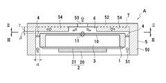
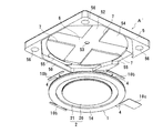
- FIG. 2 is a sectional view taken along line II-II in FIG.
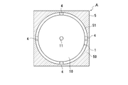
- FIG. 3 is a cross-sectional view taken along line III-III in FIG.
- FIG. 1 to 3 show a first embodiment of a piezoelectric micro blower according to the present invention, showing an example of using it as a blower for electronic equipment.
- This piezoelectric micro blower A is generally composed of an inner case 1 and an outer case 5 that covers the outer side of the inner case 1 in a non-contact manner with a predetermined gap ⁇ , and between the inner case 1 and the outer case 5 is formed. They are connected by a plurality of connecting portions 4.
- the outer case 5 has a side wall portion 50 and a top wall portion 52, and a cylindrical hollow portion 51 having an open bottom is formed therein.
- the disc-shaped inner case 1 is accommodated in the hollow portion 51 with a predetermined gap ⁇ .
- the connecting portion 4 is provided between the outer peripheral portion of the inner case 1 and the side wall portion 50 of the outer case 5.
- the inner case 1 is formed in a U-shaped cross section with an opening at the bottom, and a diaphragm 21 of the diaphragm 2 is fixed so as to close the opening of the inner case 1, and the blower chamber 3 is interposed between the inner case 1 and the diaphragm 2. Is formed.
- the diaphragm 2 of the present embodiment has a unimorph structure in which a piezoelectric element 20 made of a piezoelectric ceramic is attached to the central portion of a diaphragm 21 made of a metal thin plate. The entire plate 2 is resonantly driven in the bending mode.
- a first opening portion 11 is formed in the top plate portion (wall portion) 10 of the inner case 1 facing the center portion of the diaphragm 2.
- the top plate portion 10 of the inner case 1 is formed thin so as to resonate with the resonance drive of the diaphragm 2.
- the top plate portion (wall portion) 52 of the outer case 5 facing the top plate portion 10 of the inner case 1 is formed with a second opening portion 53 that is aligned with the first opening portion 11.
- the second opening 53 is slightly larger than the first opening 11.
- Convex portions (peripheral wall portions) 54 that are close to each other with ⁇ are formed.
- the gap ⁇ may be smaller than the gap ⁇ , and is set to a dimension that prevents the top plate portion 10 from contacting the convex portion 54 when the top plate portion 10 resonates.
- the height ⁇ of the convex portion 54 is larger than the gap ⁇ and may be equal to the gap ⁇ .
- a central space 6 communicating with the first opening portion 11 and the second opening portion 53 is formed on the inner periphery of the convex portion 54, and a plurality of (four in this case) extending radially from the central space 6 are formed on the convex portion 54.
- An inflow passage 7 (see FIG. 2) made of a groove is formed. In this embodiment, not only the inflow passage 7 but also the gap ⁇ between the convex portion 54 and the top plate portion 10 functions as an inflow passage, and the gap ⁇ communicates over the entire circumference. It can reduce and can contribute to an increase in flow rate.
- a plurality of (four in this case) connecting portions 4 are provided in the circumferential direction at portions different in phase from the inflow passage 7, and softly support the inner case 1 with respect to the outer case 5.
- the connecting portion 4 is made of a spring member such as a leaf spring, and has low spring elasticity in the direction of vibration in the bending mode of the diaphragm and high spring elasticity in a direction perpendicular to the direction of vibration in the bending mode of the diaphragm. . For this reason, when the inner case 1 vibrates in the vertical direction with the resonance drive of the diaphragm 2, the vibration is prevented from leaking to the outer case 5.
- An annular gap ⁇ is formed between the outer circumference of the inner case 1 and the inner circumference of the side wall portion 50 of the outer case 5, and external air is sucked through the gap ⁇ and passes through the inflow passage 7. Guided to the central space 6.
- the connecting portion 4 is interposed in the middle of the gap ⁇ , the connecting portion 4 is arranged at intervals in the circumferential direction, and therefore there is no possibility of air flow resistance.
- the operation of the piezoelectric micro blower A having the above-described configuration will be described.
- the diaphragm 2 is resonantly driven in the primary resonance mode or the tertiary resonance mode, thereby changing the distance between the first opening 11 and the diaphragm 2.
- the distance between the first opening 11 and the diaphragm 2 increases, the air in the central space 6 is sucked into the blower chamber 3 through the first opening 11, and conversely the first opening 11 and the diaphragm 2
- the distance decreases the air in the blower chamber 3 passes through the first opening 11 and is discharged into the central space 6.
- the diaphragm 2 Since the diaphragm 2 is driven at a high frequency, the high speed / high energy air flow discharged from the first opening 11 to the central space 6 passes through the central space 6 and is discharged from the second opening 53. . At this time, the air in the central space 6 is discharged from the second opening 53 while entraining the air, so that a continuous air flow from the inflow passage 7 toward the central space 6 occurs, and the air is jetted from the second opening 53. It is discharged continuously.
- the air flow is indicated by arrows in FIG.
- the top plate portion 10 of the inner case 1 When the top plate portion 10 of the inner case 1 is thinly formed so as to resonate with the resonance drive of the diaphragm 2, the distance between the first opening 11 and the diaphragm 2 is the diaphragm 2. Therefore, the flow rate of the air discharged from the second opening 53 is dramatically increased as compared with the case where the top plate 10 does not resonate.
- the entire top plate 10 When the entire top plate 10 is formed thin as shown in FIG. 1, the entire top plate 10 can be resonated, so that a further increase in flow rate can be realized.
- the top plate 10 may resonate in either the primary resonance mode or the tertiary resonance mode.
- the inner case 1 vibrates up and down with the resonance drive of the diaphragm 2.
- the vibration of the inner case 1 is 5 hardly leaks and energy loss can be reduced.
- a micro-blower with a large flow rate can be realized with relatively small input energy.
- the outer case 5 hardly vibrates, when the outer case 5 is fixed to a housing or a substrate, the vibration of the diaphragm 2 is not affected by the fixing structure, and characteristic fluctuations such as flow rate can be eliminated. .
- FIG. 4 shows a second embodiment of a piezoelectric microblower according to the present invention.
- the same portions as those of the piezoelectric micro blower A of the first embodiment are denoted by the same reference numerals, and redundant description is omitted.
- a convex portion (peripheral wall portion) 12 protruding upward is formed on the top surface of the top plate portion 10 of the inner case 1, and the inner surface of the top plate portion 52 of the outer case 5 is a flat surface. is there.
- An inflow passage 7 is formed in the convex portion 12 in the radial direction.
- the portion other than the convex portion 12 of the top plate portion 10 of the inner case 1, that is, the portion 10 a of the top plate portion 10 facing the central space 6 resonates up and down with the resonance drive of the diaphragm 2.
- the convex parts 54 and 12 in 1st, 2nd embodiment are not essential, and it is good also considering the upper surface of the top plate part 10 of the inner case 1 and the lower surface of the top plate part 52 of the outer case 5 as a flat surface. In this case, the entire space between the top plate portion 10 of the inner case 1 and the top plate portion 52 of the outer case 5 becomes the central space 6 and the inflow passage 7.
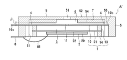
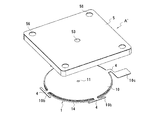
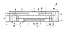
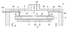
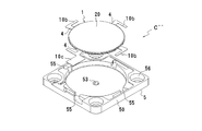
- FIGS. 5 to 7 show the microblower of the first embodiment described above, and corresponding parts are denoted by the same reference numerals except for those given new numerals, and redundant description is omitted.
- the inner case 1 of the micro blower A ′ includes a top plate 10, an annular first frame 13 fixed to the lower surface of the top plate 10, a diaphragm 2 fixed to the lower surface of the first frame 13, It has a laminated structure with an annular second frame 14 fixed to the lower surface of the diaphragm 2.
- the thickness of the blower chamber 3 is set by the thickness of the first frame 13.
- the top plate 10 is made of a disc-shaped metal plate having spring elasticity, and as shown in FIG. 6, four narrow connecting portions 4 are integrally projected at 90 ° intervals on the outer periphery thereof.
- Wide attachment portions 10b and 10c are formed at the outer end portion of the portion 4.
- One of the attachment portions 10 c protrudes from the outer case 5 in the outer peripheral direction, and this attachment portion 10 c also serves as one electrode terminal for applying a voltage to the piezoelectric element 20.
- the first frame body 13 and the second frame body 14 are also made of a metal material, and the upper and lower surfaces of the metal diaphragm 21 of the diaphragm 2 are sandwiched between the first frame body 13 and the second frame body 14, thereby
- the electrode on one side of the element 20 can be electrically connected to the electrode terminal 10c of the top plate 10 without separately wiring.
- the diaphragm 2 is obtained by bonding a diaphragm 21 and a piezoelectric element 20 with an intermediate plate 22 therebetween.
- the intermediate plate 22 is also made of a metal plate similar to the diaphragm 21, and is set so that the neutral surface of the displacement is within the range of the thickness of the intermediate plate 22 when the diaphragm 2 is bent and deformed.
- the outer case 5 is integrally formed of, for example, a resin material, and the other electrode terminal 8 is fixed to the end surface of the peripheral wall portion.
- An electrode formed on the other surface of the piezoelectric element 20 is electrically connected to the electrode terminal 8 via a lead wire 81.
- a plurality of mounting holes 56 penetrating vertically are formed in the peripheral wall portion of the outer case 5, and bolts (or screws) are inserted into the mounting holes 56 and fastened to a housing or a substrate, whereby this micro
- the blower A ′ is attached.
- the cavity 51 of the outer case 5 opens downward and the piezoelectric element 20 is exposed to the outside.
- the lower surface opening of the outer case 5 is closed with a lid so as to cover the piezoelectric element 20. May be.
- FIG. 8 shows the driving frequency and the center of the diaphragm in the connecting structure in which only the driving part (inner case + diaphragm) of the micro blower A ′ is connected by the connecting part under the following conditions.
- the displacement is compared by simulation. The simulation was performed with a configuration in which the space between the top plate 10 of the inner case 1 and the top plate 52 of the outer case 5 becomes the central space 6 (the convex portion 54 for forming the flow path is omitted).
- the driving area ( ⁇ 17 mm) of the diaphragm is a tertiary mode
- the driving area ( ⁇ 17 mm) of the top plate of the inner case is a tertiary mode different from that of the diaphragm. Vibrated.
- FIG. 9A shows a state in which the diaphragm is driven in the tertiary mode
- FIG. 9B shows a state in which the diaphragm is driven in the primary mode.
- the diameter of the piezoelectric element is substantially the same as that of the diaphragm and is larger than the inner diameter of the blower chamber.
- the top plate of the inner case vibrates in a tertiary mode having nodes at the center and its peripheral part. Since the diaphragm and the top plate of the inner case vibrate so that the outer peripheral end thereof becomes a free end, the connecting portion that supports the outer peripheral end of the inner case top plate is formed of a material having a high spring property. Is desirable.
- the flow rate can be increased compared to the case of driving in the tertiary mode ((a) of FIG. 9). It becomes possible.
- the inner case and the outer case are connected via the connecting portion having the spring elasticity, so that the vibration energy of the driving part leaks to the outer case. Energy loss can be reduced, and a desired flow rate can be obtained even if the size is reduced. Further, the flow characteristics can be maintained regardless of the mounting method. Further, since the gap ⁇ (0.1 mm) between the inner case and the convex portion functions as a flow path, there is an effect that the flow path resistance is reduced and the flow rate is increased as compared with the case where the inflow passage has the same thickness.
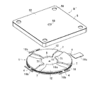
- FIGS. 10 to 12 illustrate the micro blower B of the second embodiment, and portions corresponding to the micro blower A ′ of the first embodiment are denoted by the same reference numerals, and redundant description is omitted.
- this micro blower B ′ a plurality of convex portions (peripheral wall portions) 12 are bonded to the upper surface of the top plate 10 of the inner case 1.
- a gap ⁇ is provided between the upper surface of the convex portion 12 and the top plate 52 of the outer case 5.
- a groove-shaped inflow passage 7 is formed between the convex portions 12 in the radial direction, and a throttle portion 71 is formed at the inner end of the inflow passage 7.
- the inflow passage 7 and the central space 6 communicate with each other through the throttle portion 71.
- the central space 6 is formed in a concentric circle with the first opening 11 as the center. Only the portion of the top plate 10 other than the bonding portion of the convex portion 12, that is, the portion 10 a facing the central space 6 resonates as the diaphragm 2 is driven.
- FIG. 13 and 14 show a third embodiment of a piezoelectric microblower according to the present invention.
- the same parts as those of the piezoelectric micro blowers A and B of the first and second embodiments are denoted by the same reference numerals, and redundant description is omitted.
- a plurality (four in this case) of connecting portions 4 are formed vertically on the top surface of the top plate 10 of the inner case 1, and the top plate 10 is connected to the outer case 5 via these connecting portions 4.
- the top plate 52 is fixed.
- the connecting portion 4 may be formed of a member having no spring elasticity, but a spring member is preferable.
- the radial distance R from the center (first opening 11) of the top plate 10 to the connecting portion 4 is set so that the position of the connecting portion 4 coincides with the vibration node of the top plate 10.
- Other configurations are substantially the same as in the first embodiment, but the convex portions 12 and 54 for forming the flow path are not provided. Therefore, the space between the top plate 10 of the inner case 1 and the top plate 52 of the outer case 5 becomes the central space 6.
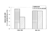
- FIG. 15 shows a driving frequency and diaphragm at the time of driving using the piezoelectric micro blower C in which the connecting portion 4 is connected perpendicularly to the vibration node and the comparative example in which the connecting portion 4 is connected to the outer peripheral end of the top plate 10.
- This is an analysis of the center displacement amount.
- the characteristic of the structure of only the drive part with respect to the connection structure in which the drive part (inner case 1 + diaphragm 2) and the outer case 5 are connected by the connection part is shown as a ratio.
- the drive frequency is 25 kHz, and indicates a frequency at which the diaphragm that vibrates in the primary resonance mode and the inner case are in a resonance state when driven at 15 Vpp.
- each part of a drive part is as follows.
- a central space 6 is formed between the top plate 10 of the inner case 1 and the top plate 52 of the outer case 5.
- Blower chamber (inner diameter, thickness) ( ⁇ 5mm, t0.15mm)
- Piezoelectric element (diameter, thickness) ( ⁇ 11mm, t0.1mm)
- Diaphragm (drive area diameter, thickness, material) ( ⁇ 11mm, t0.1mm, 42Ni)
- Connecting part (length, width, thickness, material) (0.5mm, 1mm, 0.05mm, SUS430)
- Distance R 4mm
- the left side is a case where the outer periphery is held, and the right side is a case where the node is held.
- the diaphragm and the top plate of the inner case vibrate so that their outer peripheral ends are free ends.
- the vibration node is located at the inside of the outer edge.
- the vibration node of the top plate of the inner case is almost at the same position as the vibration node.
- the outer peripheral portion which is a free end is restrained by the holding portion, and therefore the driving frequency is about 10% higher than that of the driving portion alone.
- the center displacement amount of the diaphragm which affects the flow rate characteristic is reduced to 66%.
- the drive frequency is the same as the drive frequency of the single drive part, and the difference in the center displacement of the diaphragm is also less than 1%. From this, it is understood that the energy loss due to leakage of the vibration of the inner case to the outer case is very small by connecting the connecting portion to the node of the top plate of the inner case.
- the primary resonance mode here is a vibration mode of the diaphragm, and is not a vibration mode of the top plate (wall part) of the inner case.
- the top plate of the inner case vibrates with the vibration of the diaphragm on which the piezoelectric element is formed.
- the vibration of the top plate of the inner case does not necessarily match the vibration mode of the diaphragm, and is a complicated vibration. I do.
- the diaphragm equipped with the piezoelectric element vibrates in the primary resonance mode with the outer periphery being a free end, and a node is generated in the vibration of the top plate of the inner case, and the position of the node is the outer periphery of the inner case. Located inside the edge.
- the position of this node can be obtained by individually measuring the vibration of the top plate of the inner case with an LDV (laser Doppler velocimeter). For this reason, depending on the vibration state of the diaphragm, there is a possibility that a vibration node of the inner case is located at the outer peripheral end of the top plate of the inner case.
- LDV laser Doppler velocimeter
- the reason why the center displacement amount of the diaphragm increases is not only because the top plate of the inner case is supported by the node, but also because the diameter of the piezoelectric element 20 is larger than the diameter of the blower chamber 3. Yes. That is, when the diameter of the piezoelectric element 20 is larger than the diameter of the blower chamber 3, the outer peripheral end of the piezoelectric element 20 is positioned on the first frame body 13, so that the displacement of the piezoelectric element 20 is generally caused by the first frame body 13. It is constrained and the displacement is considered to be small.
- the inner case including the diaphragm 2 is included.
- the whole 1 can be displaced without difficulty so that the outer peripheral end is a free end. Therefore, it is presumed that a large displacement of the diaphragm 2 and a large displacement of the top plate of the inner case 1 were obtained.
- the flow rate can be further increased by setting the diameter of the blower chamber 3 so as to be a resonance space.
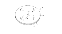
- FIGS. 16 to 18 embody the micro blower C of the third embodiment described above, and portions corresponding to those in FIG.
- the inner case 1 of the micro blower C ′ has a laminated structure of a top plate 10, an annular frame 13 fixed to the lower surface of the top plate 10, and a diaphragm 21 fixed to the lower surface of the frame 13. Yes.
- a blower chamber 3 is formed inside the frame body 13.
- the top plate 10 is made of a disc-shaped metal plate having spring elasticity, and as shown in FIG. 17, four crank-shaped connecting portions 4 are integrally formed on the outer periphery thereof.
- the connecting portion 4 is bent at a right angle with respect to the top plate 10.
- the distance R between the connecting portion 4 and the first opening 11 is set so that the connection position between the inner end 41 of the connecting portion 4 and the top plate 10 becomes a vibration node of the top plate 10.
- the outer end 42 of the connecting portion 4 protrudes in the radial direction from the top plate 10 and is supported on the inner surface of the top plate 52 of the outer case 5.
- a mounting portion 10 b formed at the distal end portion of the outer end portion 42 is supported by the support surface 55 of the outer case 5.
- One of the attachment portions 10c protrudes from the support surface 55 of the outer case 5 to the outside, and also serves as an electrode terminal.
- the connecting portion 4 can be integrally formed from the top plate 10, the structure is simplified, and the outer end 42 of the connecting portion 4 is supported by the inner surface of the top plate 52 of the outer case 5.
- the inner case 1 can be stably supported with respect to the outer case 5.
- the connecting portion 4 since the connecting portion 4 is connected to the vibration node of the top plate 10, the connecting portion 4 does not substantially vibrate even when the top plate 10 vibrates. That is, since the connection part 4 does not require elasticity, the thing of arbitrary materials can be selected.
- the connecting portion 4 extends in the radial direction on the same plane as the top plate 10. Slits 10d are formed on both sides of the connecting portion 4, and the cut amount of these slits 10d, that is, the connecting portion 4 By appropriately setting the distance R between the inner end 41 and the center of the top plate 10 (first opening 11), the inner end 41 of the connecting portion 4 is adjusted so as to be a vibration node of the top plate 10.
- connection portion 4 There is a frame 13 interposed between the top plate 10 and the diaphragm 21 at a position corresponding to the connection portion 4 so that the connection portion 4 does not come into contact with the top plate 10 at the outer side of the node of vibration.
- a notch 13a is formed, and a recess may be used instead of the notch 13a.
- the present invention is not limited to the above-described embodiments or examples.
- the example in which the top plate portion of the inner case corresponding to the central space is vibrated with the vibration of the diaphragm has been shown, but the top plate portion of the inner case is not necessarily vibrated.
- the shape of the inflow passage is not limited to a shape linearly extending in the radial direction from the central space, and can be arbitrarily selected. Also, the number of inflow passages is arbitrary and can be selected according to the flow rate and the degree of noise.
- the shape of the piezoelectric element is not limited to a disk shape, but may be a ring shape.
- the member on the inner case side that connects one end of the connecting portion may be any member, and is not limited to the top plate 10 as in the embodiment, but the first frame body interposed between the top plate 10 and the diaphragm 21. 13 or a diaphragm 21 may be used.
- A, A ′, B, B ′, C, C ′, C ′′ Piezoelectric micro blower 1 Inner case 10 Top plate (wall) 11 1st opening part 12 Convex part (circumferential wall part) 13 1st frame 14 2nd frame 2 Diaphragm 20 Piezoelectric element 21 Diaphragm 3 Blower chamber 4 Connection part 5 Outer case 51 Cavity part 52 Top plate part (wall part) 53 2nd opening part 54 convex part (circumferential wall part) 6 Central space 7 Inflow passage
Landscapes
- Engineering & Computer Science (AREA)
- Mechanical Engineering (AREA)
- General Engineering & Computer Science (AREA)
- Reciprocating Pumps (AREA)
- Micromachines (AREA)
Abstract
L'invention porte sur une microsoufflante piézoélectrique dans laquelle les vibrations d'une plaque vibrante ne fuient pas aisément vers l'extérieur et les pertes d'énergie peuvent être réduites. La microsoufflante comporte un boîtier interne (1) dans lequel la périphérie d'une plaque vibrante (2), qui comprend un élément piézoélectrique (20), est fixée, et une chambre de soufflante (3) comprend la plaque vibrante ; et un boîtier externe (5) qui recouvre le côté extérieur du boîtier interne sans contact et avec un intervalle spécifié. Le boîtier interne (1) est supporté de façon élastique par le boîtier externe (5) par le biais d'une pluralité d'éléments de liaison (4). Une première ouverture (11) est formée dans un élément de plaque supérieur (10) du boîtier interne (1) opposé à la partie centrale de la plaque vibrante. Une seconde ouverture (53) est formée dans un élément de plaque supérieur (52) du boîtier externe (5) opposé à la première ouverture. Un espace central (6) dans lequel est introduit le fluide d’arrivée provenant de l'extérieur, par le biais de l'intervalle entre les deux boîtiers, est formé entre les deux éléments de plaque supérieurs (10, 52). De l'air est aspiré dans l'espace central (6) et déchargé à partir de la seconde ouverture (53) par actionnement de la plaque vibrante (2) dans le mode flexion. Les éléments de liaison (4) empêchent la fuite des vibrations de la plaque vibrante (2) du boîtier interne (1) au boîtier externe (5), ce qui réduit les pertes d'énergie.
Priority Applications (6)
| Application Number | Priority Date | Filing Date | Title |
|---|---|---|---|
| JP2010515855A JP5115626B2 (ja) | 2008-06-03 | 2009-06-01 | 圧電マイクロブロア |
| CN2009801211882A CN102046978B (zh) | 2008-06-03 | 2009-06-01 | 压电微型鼓风机 |
| EP16163739.2A EP3073114B1 (fr) | 2008-06-03 | 2009-06-01 | Microsoufflante piézoélectrique |
| EP09758275.3A EP2306018B1 (fr) | 2008-06-03 | 2009-06-01 | Microsoufflante piézoélectrique |
| US12/958,573 US8596998B2 (en) | 2008-06-03 | 2010-12-02 | Piezoelectric micro-blower |
| US14/066,958 US9109592B2 (en) | 2008-06-03 | 2013-10-30 | Piezoelectric micro-blower |
Applications Claiming Priority (2)
| Application Number | Priority Date | Filing Date | Title |
|---|---|---|---|
| JP2008145395 | 2008-06-03 | ||
| JP2008-145395 | 2008-06-03 |
Related Child Applications (1)
| Application Number | Title | Priority Date | Filing Date |
|---|---|---|---|
| US12/958,573 Continuation US8596998B2 (en) | 2008-06-03 | 2010-12-02 | Piezoelectric micro-blower |
Publications (1)
| Publication Number | Publication Date |
|---|---|
| WO2009148008A1 true WO2009148008A1 (fr) | 2009-12-10 |
Family
ID=41398086
Family Applications (1)
| Application Number | Title | Priority Date | Filing Date |
|---|---|---|---|
| PCT/JP2009/059951 WO2009148008A1 (fr) | 2008-06-03 | 2009-06-01 | Microsoufflante piézoélectrique |
Country Status (5)
| Country | Link |
|---|---|
| US (2) | US8596998B2 (fr) |
| EP (2) | EP2306018B1 (fr) |
| JP (2) | JP5115626B2 (fr) |
| CN (2) | CN102046978B (fr) |
| WO (1) | WO2009148008A1 (fr) |
Cited By (16)
| Publication number | Priority date | Publication date | Assignee | Title |
|---|---|---|---|---|
| WO2011145544A1 (fr) * | 2010-05-21 | 2011-11-24 | 株式会社村田製作所 | Pompe à fluide |
| WO2012140931A1 (fr) * | 2011-04-11 | 2012-10-18 | 株式会社村田製作所 | Dispositif de régulation de fluide et méthode de raccord de pompe |
| WO2012140932A1 (fr) * | 2011-04-11 | 2012-10-18 | 株式会社村田製作所 | Soupape active et dispositif de régulation de fluide |
| JP2014088790A (ja) * | 2012-10-29 | 2014-05-15 | Murata Mfg Co Ltd | ブロア |
| WO2015045727A1 (fr) * | 2013-09-24 | 2015-04-02 | 株式会社村田製作所 | Dispositif de commande de gaz |
| TWI503654B (zh) * | 2009-12-29 | 2015-10-11 | Foxconn Tech Co Ltd | 電子裝置及其微型液體冷卻裝置 |
| JP2017198164A (ja) * | 2016-04-28 | 2017-11-02 | シャープ株式会社 | 送風装置 |
| US10107281B2 (en) | 2013-03-22 | 2018-10-23 | Murata Manufacturing Co., Ltd. | Piezoelectric blower |
| JP2019039436A (ja) * | 2014-10-23 | 2019-03-14 | 株式会社村田製作所 | 流体制御装置 |
| JP2019044770A (ja) * | 2017-08-31 | 2019-03-22 | 研能科技股▲ふん▼有限公司 | 気体輸送装置 |
| JP2019044769A (ja) * | 2017-08-31 | 2019-03-22 | 研能科技股▲ふん▼有限公司 | 気体輸送装置 |
| WO2019111922A1 (fr) * | 2017-12-08 | 2019-06-13 | 株式会社村田製作所 | Pompe |
| WO2019124060A1 (fr) * | 2017-12-22 | 2019-06-27 | 株式会社村田製作所 | Pompe |
| JP2019128349A (ja) * | 2018-01-26 | 2019-08-01 | 研能科技股▲ふん▼有限公司 | ガス検出装置 |
| JP2019203877A (ja) * | 2018-03-30 | 2019-11-28 | 研能科技股▲ふん▼有限公司 | 作動検知モジュール |
| CN112211807A (zh) * | 2015-04-27 | 2021-01-12 | 株式会社村田制作所 | 泵 |
Families Citing this family (104)
| Publication number | Priority date | Publication date | Assignee | Title |
|---|---|---|---|---|
| EP2306018B1 (fr) * | 2008-06-03 | 2016-05-11 | Murata Manufacturing Co. Ltd. | Microsoufflante piézoélectrique |
| DE102011078853B4 (de) * | 2011-07-08 | 2014-01-23 | Osram Gmbh | Erzeugung eines Luftstroms mittels Schwingungen |
| JP5900155B2 (ja) * | 2011-09-06 | 2016-04-06 | 株式会社村田製作所 | 流体制御装置 |
| JP5528404B2 (ja) | 2011-09-06 | 2014-06-25 | 株式会社村田製作所 | 流体制御装置 |
| JP5682513B2 (ja) * | 2011-09-06 | 2015-03-11 | 株式会社村田製作所 | 流体制御装置 |
| DE102012101861A1 (de) | 2012-03-06 | 2013-09-12 | Continental Automotive Gmbh | Mikropumpe mit gasdurchlässigem, aber flüssigkeitsundurchlässigen Gewebe im Ansaugbereich |
| DE102012101859A1 (de) | 2012-03-06 | 2013-09-12 | Continental Automotive Gmbh | Drucksensor für ein Aufprallsensorsystem |
| JP5761455B2 (ja) * | 2012-05-09 | 2015-08-12 | 株式会社村田製作所 | 冷却装置、加熱冷却装置 |
| TWI475180B (zh) * | 2012-05-31 | 2015-03-01 | Ind Tech Res Inst | 合成噴流裝置 |
| WO2013187271A1 (fr) * | 2012-06-11 | 2013-12-19 | 株式会社村田製作所 | Soufflante |
| CN103016296B (zh) * | 2012-12-13 | 2015-08-26 | 江苏大学 | 基于合成射流的压电微泵 |
| JP5987919B2 (ja) * | 2013-01-18 | 2016-09-07 | 株式会社村田製作所 | 揚液装置及び揚液方法 |
| CN105026050A (zh) * | 2013-03-14 | 2015-11-04 | 通用电气公司 | 低共振声音合成喷射器结构 |
| CN104185356B (zh) | 2013-05-24 | 2017-09-29 | 华为技术有限公司 | 光模块散热系统 |
| KR101435899B1 (ko) * | 2013-06-10 | 2014-09-04 | 김정훈 | 단일 액추에이터로 동작하는 냉각 분사 장치 |
| JP2015004645A (ja) * | 2013-06-24 | 2015-01-08 | 株式会社村田製作所 | 酸素濃度測定装置 |
| JP6287089B2 (ja) * | 2013-11-13 | 2018-03-07 | 村田機械株式会社 | 基板浮上装置、基板移載装置、および基板搬送装置 |
| GB201322103D0 (en) * | 2013-12-13 | 2014-01-29 | The Technology Partnership Plc | Fluid pump |
| EP2890228A1 (fr) * | 2013-12-24 | 2015-07-01 | Samsung Electronics Co., Ltd | Appareil de rayonnement |
| EP3488880B1 (fr) * | 2014-01-30 | 2020-07-01 | Murata Manufacturing Co., Ltd. | Dispositif d'aspiration |
| CN108317093B (zh) * | 2014-02-21 | 2019-12-10 | 株式会社村田制作所 | 鼓风机 |
| EP3109472B1 (fr) * | 2014-02-21 | 2019-10-30 | Murata Manufacturing Co., Ltd. | Dispositif de commande de fluide et pompe |
| CN106536704B (zh) | 2014-07-08 | 2020-03-06 | 国立研究开发法人产业技术综合研究所 | 核酸扩增装置、核酸扩增方法以及核酸扩增用芯片 |
| JP5907322B1 (ja) * | 2014-07-11 | 2016-04-26 | 株式会社村田製作所 | 吸引装置 |
| GB2542527B (en) * | 2014-07-16 | 2020-08-26 | Murata Manufacturing Co | Fluid control device |
| TWI553230B (zh) * | 2014-09-15 | 2016-10-11 | 研能科技股份有限公司 | 微型氣壓動力裝置 |
| JP6380075B2 (ja) * | 2014-12-15 | 2018-08-29 | 株式会社村田製作所 | ブロア |
| US10744295B2 (en) | 2015-01-13 | 2020-08-18 | ResMed Pty Ltd | Respiratory therapy apparatus |
| JP6572619B2 (ja) * | 2015-05-11 | 2019-09-11 | 株式会社村田製作所 | ブロア |
| EP3297697B1 (fr) * | 2015-05-18 | 2022-05-11 | Smith & Nephew plc | Appareil de traitement des plaies par pression négative |
| JP2017002942A (ja) * | 2015-06-05 | 2017-01-05 | 株式会社ジェイテクト | 転がり軸受装置 |
| CN107614875B (zh) * | 2015-06-11 | 2019-08-20 | 株式会社村田制作所 | 泵 |
| TWI557321B (zh) * | 2015-06-25 | 2016-11-11 | 科際精密股份有限公司 | 壓電泵及其操作方法 |
| CA2995469C (fr) | 2015-08-13 | 2023-10-03 | Smith & Nephew, Inc. | Systemes et procedes pour la mise en oeuvre d'une therapie par pression reduite |
| GB2557088B (en) | 2015-08-31 | 2021-05-19 | Murata Manufacturing Co | Blower |
| CN108138759B (zh) * | 2015-10-05 | 2020-02-21 | 株式会社村田制作所 | 流体控制装置、减压装置以及加压装置 |
| WO2017059660A1 (fr) * | 2015-10-08 | 2017-04-13 | 广东奥迪威传感科技股份有限公司 | Structure de pompe à air piézoélectrique miniature |
| US9976673B2 (en) | 2016-01-29 | 2018-05-22 | Microjet Technology Co., Ltd. | Miniature fluid control device |
| US10487821B2 (en) | 2016-01-29 | 2019-11-26 | Microjet Technology Co., Ltd. | Miniature fluid control device |
| EP3203078B1 (fr) | 2016-01-29 | 2021-05-26 | Microjet Technology Co., Ltd | Dispositif pneumatique miniature |
| EP3203077B1 (fr) | 2016-01-29 | 2021-06-16 | Microjet Technology Co., Ltd | Actionneur piézoélectrique |
| US10529911B2 (en) | 2016-01-29 | 2020-01-07 | Microjet Technology Co., Ltd. | Piezoelectric actuator |
| EP3203080B1 (fr) | 2016-01-29 | 2021-09-22 | Microjet Technology Co., Ltd | Dispositif pneumatique miniature |
| US10487820B2 (en) | 2016-01-29 | 2019-11-26 | Microjet Technology Co., Ltd. | Miniature pneumatic device |
| US10388849B2 (en) | 2016-01-29 | 2019-08-20 | Microjet Technology Co., Ltd. | Piezoelectric actuator |
| US10385838B2 (en) | 2016-01-29 | 2019-08-20 | Microjet Technology Co., Ltd. | Miniature fluid control device |
| US10451051B2 (en) | 2016-01-29 | 2019-10-22 | Microjet Technology Co., Ltd. | Miniature pneumatic device |
| US10388850B2 (en) | 2016-01-29 | 2019-08-20 | Microjet Technology Co., Ltd. | Piezoelectric actuator |
| TWM539009U (zh) * | 2016-01-29 | 2017-04-01 | Microjet Technology Co Ltd | 微型氣壓動力裝置 |
| US10584695B2 (en) | 2016-01-29 | 2020-03-10 | Microjet Technology Co., Ltd. | Miniature fluid control device |
| CN105822527B (zh) * | 2016-03-24 | 2017-12-05 | 北京理工大学 | 利用压电陶瓷驱动的多功能流体分配系统及其驱动方法 |
| JP2018012154A (ja) | 2016-07-20 | 2018-01-25 | 株式会社マキタ | 電動作業機 |
| WO2018021514A1 (fr) * | 2016-07-29 | 2018-02-01 | 株式会社村田製作所 | Soupape et dispositif de régulation de gaz |
| TWI625468B (zh) | 2016-09-05 | 2018-06-01 | 研能科技股份有限公司 | 流體控制裝置 |
| TWI602995B (zh) | 2016-09-05 | 2017-10-21 | 研能科技股份有限公司 | 流體控制裝置 |
| TWI613367B (zh) | 2016-09-05 | 2018-02-01 | 研能科技股份有限公司 | 流體控制裝置 |
| TWI683959B (zh) * | 2016-09-05 | 2020-02-01 | 研能科技股份有限公司 | 壓電致動器及其所適用之微型流體控制裝置 |
| TWI606936B (zh) | 2016-09-05 | 2017-12-01 | 研能科技股份有限公司 | 流體控制裝置 |
| US10634130B2 (en) * | 2016-09-07 | 2020-04-28 | Sung Won Moon | Compact voice coil driven high flow fluid pumps and methods |
| US10683861B2 (en) | 2016-11-10 | 2020-06-16 | Microjet Technology Co., Ltd. | Miniature pneumatic device |
| US10746169B2 (en) | 2016-11-10 | 2020-08-18 | Microjet Technology Co., Ltd. | Miniature pneumatic device |
| US10655620B2 (en) | 2016-11-10 | 2020-05-19 | Microjet Technology Co., Ltd. | Miniature fluid control device |
| TWI622701B (zh) * | 2017-01-20 | 2018-05-01 | 研能科技股份有限公司 | 流體輸送裝置 |
| WO2018150263A1 (fr) | 2017-02-15 | 2018-08-23 | Smith & Nephew Pte. Limited | Appareils de traitement de plaie par pression négative et leurs procédés d'utilisation |
| TWI667636B (zh) * | 2017-08-21 | 2019-08-01 | 研能科技股份有限公司 | 具致動傳感模組之裝置 |
| TWI650545B (zh) * | 2017-08-22 | 2019-02-11 | 研能科技股份有限公司 | 致動傳感模組 |
| CN109424520B (zh) * | 2017-08-31 | 2021-03-02 | 研能科技股份有限公司 | 气体输送装置 |
| CN109424522B (zh) * | 2017-08-31 | 2021-02-09 | 研能科技股份有限公司 | 气体输送装置 |
| CN109424528B (zh) * | 2017-08-31 | 2021-02-23 | 研能科技股份有限公司 | 气体输送装置 |
| TWI683059B (zh) | 2017-08-31 | 2020-01-21 | 研能科技股份有限公司 | 氣體輸送裝置 |
| CN109424521B (zh) * | 2017-08-31 | 2021-02-23 | 研能科技股份有限公司 | 气体输送装置 |
| TW201912248A (zh) * | 2017-08-31 | 2019-04-01 | 研能科技股份有限公司 | 氣體輸送裝置 |
| WO2019063467A1 (fr) | 2017-09-29 | 2019-04-04 | T.J.Smith And Nephew,Limited | Appareil de traitement des plaies par pression négative à panneaux amovibles |
| TWI650484B (zh) * | 2017-10-27 | 2019-02-11 | 研能科技股份有限公司 | 氣體輸送裝置 |
| CN109723627B (zh) * | 2017-10-27 | 2021-02-23 | 研能科技股份有限公司 | 气体输送装置 |
| CN109723626B (zh) * | 2017-10-27 | 2021-04-06 | 研能科技股份有限公司 | 气体输送装置 |
| CN109899327B (zh) * | 2017-12-07 | 2021-09-21 | 昆山纬绩资通有限公司 | 气流产生装置 |
| US10620106B2 (en) | 2017-12-15 | 2020-04-14 | Microjet Technology Co., Ltd. | Particulate matter measuring device |
| WO2019124029A1 (fr) * | 2017-12-22 | 2019-06-27 | 株式会社村田製作所 | Pompe |
| GB201813282D0 (en) | 2018-08-15 | 2018-09-26 | Smith & Nephew | System for medical device activation and opertion |
| TWI635291B (zh) * | 2017-12-29 | 2018-09-11 | 研能科技股份有限公司 | 微型丙酮檢測裝置 |
| TWI661185B (zh) * | 2018-01-08 | 2019-06-01 | 研能科技股份有限公司 | 氣體檢測裝置 |
| WO2019159501A1 (fr) * | 2018-02-16 | 2019-08-22 | 株式会社村田製作所 | Dispositif de régulation de fluide |
| TWI660724B (zh) * | 2018-03-16 | 2019-06-01 | 研能科技股份有限公司 | 正壓呼吸裝置 |
| GB201804347D0 (en) | 2018-03-19 | 2018-05-02 | Smith & Nephew Inc | Securing control of settings of negative pressure wound therapy apparatuses and methods for using the same |
| US11559619B2 (en) | 2018-04-30 | 2023-01-24 | Smith & Nephew Asia Pacific Pte. Limited | Systems and methods for controlling dual mode negative pressure wound therapy apparatus |
| GB201806988D0 (en) | 2018-04-30 | 2018-06-13 | Quintanar Felix Clarence | Power source charging for negative pressure wound therapy apparatus |
| TWI681120B (zh) | 2018-05-21 | 2020-01-01 | 研能科技股份有限公司 | 微型輸送裝置 |
| GB201808438D0 (en) | 2018-05-23 | 2018-07-11 | Smith & Nephew | Systems and methods for determining blockages in a negative pressure wound therapy system |
| WO2019230189A1 (fr) * | 2018-05-29 | 2019-12-05 | 株式会社村田製作所 | Dispositif de commande de fluide |
| US20210340969A1 (en) | 2018-06-26 | 2021-11-04 | Mst Innovation Gmbh | Improved micropump |
| JP2020020283A (ja) * | 2018-07-31 | 2020-02-06 | セイコーエプソン株式会社 | ダイヤフラム式圧縮機、冷却機、プロジェクター及び流体の圧縮方法 |
| DE102018120782B3 (de) | 2018-08-24 | 2019-08-22 | Bartels Mikrotechnik Gmbh | Mikrogebläse |
| JP7218566B2 (ja) * | 2018-12-21 | 2023-02-07 | セイコーエプソン株式会社 | 変位拡大装置、ダイヤフラム式圧縮機、冷却ユニット、プロジェクター、記録装置及び三次元造形物製造装置 |
| JP2020111434A (ja) * | 2019-01-11 | 2020-07-27 | ヒューレット−パッカード デベロップメント カンパニー エル.ピー.Hewlett‐Packard Development Company, L.P. | ブロアを備えた光学メディアセンサ |
| WO2021049460A1 (fr) * | 2019-09-11 | 2021-03-18 | 京セラ株式会社 | Pompe piézoélectrique et unité de pompe |
| CN110594137A (zh) * | 2019-10-28 | 2019-12-20 | 南京航空航天大学 | 一种板式无阀压电泵及其工作方法 |
| TWI747076B (zh) * | 2019-11-08 | 2021-11-21 | 研能科技股份有限公司 | 行動裝置散熱組件 |
| CN113339244A (zh) * | 2020-02-18 | 2021-09-03 | 研能科技股份有限公司 | 薄型气体传输装置 |
| TWI709208B (zh) | 2020-02-18 | 2020-11-01 | 研能科技股份有限公司 | 薄型氣體傳輸裝置 |
| CN111779656B (zh) * | 2020-06-17 | 2022-05-10 | 长春大学 | 一种双摆式压电风机 |
| CN113464410B (zh) * | 2021-08-19 | 2022-03-22 | 浙江大学 | 一种压力无级可调的大流量压电泵 |
| WO2023019493A1 (fr) * | 2021-08-19 | 2023-02-23 | 浙江大学 | Pompe piézoélectrique à haut débit et à pression réglable en continu |
| USD991984S1 (en) * | 2021-11-30 | 2023-07-11 | Murata Manufacturing Co., Ltd. | Piezoelectric pump |
Citations (6)
| Publication number | Priority date | Publication date | Assignee | Title |
|---|---|---|---|---|
| JPS58140491A (ja) * | 1982-02-16 | 1983-08-20 | Matsushita Electric Ind Co Ltd | 流れ発生装置 |
| JPS642783B2 (fr) | 1983-11-14 | 1989-01-18 | Ebara Mfg | |
| JP2005113918A (ja) | 2003-10-07 | 2005-04-28 | Samsung Electronics Co Ltd | バルブレスマイクロ空気供給装置 |
| JP2006522896A (ja) | 2003-04-09 | 2006-10-05 | ザ テクノロジー パートナーシップ ピーエルシー | ガス流発生器 |
| WO2008069266A1 (fr) * | 2006-12-09 | 2008-06-12 | Murata Manufacturing Co., Ltd. | Micro-ventilateur piézoélectrique |
| WO2009050990A1 (fr) * | 2007-10-16 | 2009-04-23 | Murata Manufacturing Co., Ltd. | Microsoufflerie piézoélectrique |
Family Cites Families (23)
| Publication number | Priority date | Publication date | Assignee | Title |
|---|---|---|---|---|
| US4231287A (en) * | 1978-05-01 | 1980-11-04 | Physics International Company | Spring diaphragm |
| JPS59221485A (ja) * | 1983-05-31 | 1984-12-13 | Sharp Corp | ポンプ |
| JPS642793A (en) | 1987-06-23 | 1989-01-06 | Mitsubishi Electric Corp | Laser beam cutting method for al |
| JP2652980B2 (ja) | 1990-09-28 | 1997-09-10 | 日本電気株式会社 | ディスク装置 |
| JP2002242898A (ja) * | 2001-02-14 | 2002-08-28 | Sony Corp | 圧電ファン |
| US6663351B2 (en) * | 2001-03-15 | 2003-12-16 | Samsung Electronics Co., Ltd. | Piezoelectric actuated elastic membrane for a compressor and method for controlling the same |
| DE10135569B4 (de) * | 2001-07-20 | 2007-10-25 | Bartels Mikrotechnik Gmbh | Mikromechanisches Bauteil |
| DE10233235B4 (de) * | 2002-07-22 | 2004-07-22 | Siemens Ag | Pumpvorrichtung und Verfahren zur Herstellung der Pumpvorrichtung |
| JP2004332705A (ja) | 2003-05-09 | 2004-11-25 | Honda Motor Co Ltd | マイクロポンプ |
| WO2005012729A1 (fr) * | 2003-08-04 | 2005-02-10 | Nec Corporation | Pompe a membrane et systeme de refroidissement equipe d'une telle pompe a membrane |
| EP1515043B1 (fr) * | 2003-09-12 | 2006-11-22 | Samsung Electronics Co., Ltd. | Pompe à membrane pour air de refroidissement |
| JP2005229038A (ja) | 2004-02-16 | 2005-08-25 | Hitachi Ltd | 液冷システム及びそれを備えた電子機器 |
| EP1828601A1 (fr) * | 2004-12-22 | 2007-09-05 | Matsushita Electric Works, Ltd. | Appareil de regulation des debits de liquide |
| JP2006207436A (ja) * | 2005-01-26 | 2006-08-10 | Matsushita Electric Works Ltd | 圧電ダイヤフラムポンプ |
| JP4887652B2 (ja) * | 2005-04-21 | 2012-02-29 | ソニー株式会社 | 噴流発生装置及び電子機器 |
| EP1722412B1 (fr) * | 2005-05-02 | 2012-08-29 | Sony Corporation | Système de jet d' atomisation et dispositif electronique associé |
| CN100365278C (zh) * | 2005-06-04 | 2008-01-30 | 胡军 | 一种用于制造微型泵的压电陶瓷片和微型气泵 |
| CN2846796Y (zh) * | 2005-10-14 | 2006-12-13 | 北京工业大学 | 内置波纹渠道无阀压电泵 |
| JP2007222727A (ja) * | 2006-02-22 | 2007-09-06 | Sony Corp | 振動アクチュエータ及び噴流発生装置 |
| CN101438057A (zh) * | 2006-03-07 | 2009-05-20 | 流体公司 | 流体能量传递装置 |
| US7608984B2 (en) * | 2006-05-15 | 2009-10-27 | Adaptivenergy, Llc | Motion amplification using piezoelectric element |
| EP2306018B1 (fr) * | 2008-06-03 | 2016-05-11 | Murata Manufacturing Co. Ltd. | Microsoufflante piézoélectrique |
| TW201011954A (en) * | 2008-09-15 | 2010-03-16 | Micro Base Technology Corp | Conduction wire structure applied to the inner of micro piezoelectric pump |
-
2009
- 2009-06-01 EP EP09758275.3A patent/EP2306018B1/fr active Active
- 2009-06-01 WO PCT/JP2009/059951 patent/WO2009148008A1/fr active Application Filing
- 2009-06-01 EP EP16163739.2A patent/EP3073114B1/fr active Active
- 2009-06-01 JP JP2010515855A patent/JP5115626B2/ja active Active
- 2009-06-01 CN CN2009801211882A patent/CN102046978B/zh active Active
- 2009-06-01 CN CN201310525885.2A patent/CN103527452A/zh active Pending
-
2010
- 2010-12-02 US US12/958,573 patent/US8596998B2/en active Active
-
2012
- 2012-10-10 JP JP2012224911A patent/JP5168426B2/ja active Active
-
2013
- 2013-10-30 US US14/066,958 patent/US9109592B2/en active Active
Patent Citations (6)
| Publication number | Priority date | Publication date | Assignee | Title |
|---|---|---|---|---|
| JPS58140491A (ja) * | 1982-02-16 | 1983-08-20 | Matsushita Electric Ind Co Ltd | 流れ発生装置 |
| JPS642783B2 (fr) | 1983-11-14 | 1989-01-18 | Ebara Mfg | |
| JP2006522896A (ja) | 2003-04-09 | 2006-10-05 | ザ テクノロジー パートナーシップ ピーエルシー | ガス流発生器 |
| JP2005113918A (ja) | 2003-10-07 | 2005-04-28 | Samsung Electronics Co Ltd | バルブレスマイクロ空気供給装置 |
| WO2008069266A1 (fr) * | 2006-12-09 | 2008-06-12 | Murata Manufacturing Co., Ltd. | Micro-ventilateur piézoélectrique |
| WO2009050990A1 (fr) * | 2007-10-16 | 2009-04-23 | Murata Manufacturing Co., Ltd. | Microsoufflerie piézoélectrique |
Non-Patent Citations (1)
| Title |
|---|
| See also references of EP2306018A4 * |
Cited By (34)
| Publication number | Priority date | Publication date | Assignee | Title |
|---|---|---|---|---|
| TWI503654B (zh) * | 2009-12-29 | 2015-10-11 | Foxconn Tech Co Ltd | 電子裝置及其微型液體冷卻裝置 |
| EP3623624A1 (fr) * | 2010-05-21 | 2020-03-18 | Murata Manufacturing Co., Ltd. | Pompe a fluides |
| CN102597520A (zh) * | 2010-05-21 | 2012-07-18 | 株式会社村田制作所 | 流体泵 |
| WO2011145544A1 (fr) * | 2010-05-21 | 2011-11-24 | 株式会社村田製作所 | Pompe à fluide |
| US8747080B2 (en) | 2010-05-21 | 2014-06-10 | Murata Manufacturing Co., Ltd. | Fluid pump |
| JP5494801B2 (ja) * | 2010-05-21 | 2014-05-21 | 株式会社村田製作所 | 流体ポンプ |
| EP2557312A4 (fr) * | 2010-05-21 | 2018-01-03 | Murata Manufacturing Co., Ltd. | Pompe à fluide |
| JP2014098396A (ja) * | 2010-05-21 | 2014-05-29 | Murata Mfg Co Ltd | 流体ポンプ |
| JP2015092082A (ja) * | 2011-04-11 | 2015-05-14 | 株式会社村田製作所 | 流体制御装置およびポンプ接続方法 |
| WO2012140932A1 (fr) * | 2011-04-11 | 2012-10-18 | 株式会社村田製作所 | Soupape active et dispositif de régulation de fluide |
| WO2012140931A1 (fr) * | 2011-04-11 | 2012-10-18 | 株式会社村田製作所 | Dispositif de régulation de fluide et méthode de raccord de pompe |
| JP5776767B2 (ja) * | 2011-04-11 | 2015-09-09 | 株式会社村田製作所 | 流体制御装置およびポンプ接続方法 |
| JP5500310B2 (ja) * | 2011-04-11 | 2014-05-21 | 株式会社村田製作所 | アクティブバルブ、流体制御装置 |
| JP2014088790A (ja) * | 2012-10-29 | 2014-05-15 | Murata Mfg Co Ltd | ブロア |
| US10107281B2 (en) | 2013-03-22 | 2018-10-23 | Murata Manufacturing Co., Ltd. | Piezoelectric blower |
| WO2015045727A1 (fr) * | 2013-09-24 | 2015-04-02 | 株式会社村田製作所 | Dispositif de commande de gaz |
| JPWO2015045727A1 (ja) * | 2013-09-24 | 2017-03-09 | 株式会社村田製作所 | 気体制御装置 |
| US10648463B2 (en) | 2013-09-24 | 2020-05-12 | Murata Manufacturing Co., Ltd. | Gas control device |
| JP2019039436A (ja) * | 2014-10-23 | 2019-03-14 | 株式会社村田製作所 | 流体制御装置 |
| CN112211807A (zh) * | 2015-04-27 | 2021-01-12 | 株式会社村田制作所 | 泵 |
| CN112211807B (zh) * | 2015-04-27 | 2022-07-05 | 株式会社村田制作所 | 泵 |
| JP2017198164A (ja) * | 2016-04-28 | 2017-11-02 | シャープ株式会社 | 送風装置 |
| JP2019044769A (ja) * | 2017-08-31 | 2019-03-22 | 研能科技股▲ふん▼有限公司 | 気体輸送装置 |
| JP2019044770A (ja) * | 2017-08-31 | 2019-03-22 | 研能科技股▲ふん▼有限公司 | 気体輸送装置 |
| JP7137407B2 (ja) | 2017-08-31 | 2022-09-14 | 研能科技股▲ふん▼有限公司 | 気体輸送装置 |
| WO2019111922A1 (fr) * | 2017-12-08 | 2019-06-13 | 株式会社村田製作所 | Pompe |
| JPWO2019124060A1 (ja) * | 2017-12-22 | 2020-04-23 | 株式会社村田製作所 | ポンプ |
| WO2019124060A1 (fr) * | 2017-12-22 | 2019-06-27 | 株式会社村田製作所 | Pompe |
| US11795934B2 (en) | 2017-12-22 | 2023-10-24 | Murata Manufacturing Co., Ltd. | Piezoelectric pump with an upper and lower vibrating body |
| JP2019128349A (ja) * | 2018-01-26 | 2019-08-01 | 研能科技股▲ふん▼有限公司 | ガス検出装置 |
| JP7152297B2 (ja) | 2018-01-26 | 2022-10-12 | 研能科技股▲ふん▼有限公司 | ガス検出装置 |
| JP7152297B6 (ja) | 2018-01-26 | 2022-10-31 | 研能科技股▲ふん▼有限公司 | ガス検出装置 |
| JP2019203877A (ja) * | 2018-03-30 | 2019-11-28 | 研能科技股▲ふん▼有限公司 | 作動検知モジュール |
| JP7064459B2 (ja) | 2018-03-30 | 2022-05-10 | 研能科技股▲ふん▼有限公司 | 作動検知モジュール |
Also Published As
| Publication number | Publication date |
|---|---|
| US20110076170A1 (en) | 2011-03-31 |
| JPWO2009148008A1 (ja) | 2011-10-27 |
| EP2306018A4 (fr) | 2014-11-19 |
| US8596998B2 (en) | 2013-12-03 |
| CN102046978A (zh) | 2011-05-04 |
| EP2306018A1 (fr) | 2011-04-06 |
| EP3073114B1 (fr) | 2018-07-25 |
| US20140178220A1 (en) | 2014-06-26 |
| US9109592B2 (en) | 2015-08-18 |
| JP2013050108A (ja) | 2013-03-14 |
| JP5168426B2 (ja) | 2013-03-21 |
| JP5115626B2 (ja) | 2013-01-09 |
| CN103527452A (zh) | 2014-01-22 |
| EP2306018B1 (fr) | 2016-05-11 |
| EP3073114A1 (fr) | 2016-09-28 |
| CN102046978B (zh) | 2013-11-20 |
Similar Documents
| Publication | Publication Date | Title |
|---|---|---|
| JP5115626B2 (ja) | 圧電マイクロブロア | |
| JP5287854B2 (ja) | 圧電マイクロブロア | |
| JP5110159B2 (ja) | 圧電マイクロブロア | |
| JP5333012B2 (ja) | マイクロブロア | |
| US8678787B2 (en) | Piezoelectric micro-blower | |
| JP5012889B2 (ja) | 圧電マイクロブロア | |
| KR101333542B1 (ko) | 유체 펌프 | |
| JP5177331B1 (ja) | ポンプ装置 | |
| US8272851B2 (en) | Fluidic energy transfer devices | |
| WO2010035862A1 (fr) | Pompe piézoélectrique | |
| JP4957501B2 (ja) | 圧電マイクロブロア | |
| JP2009097414A (ja) | 圧電ポンプおよびその製造方法 | |
| JP2023126991A (ja) | ポンプ及び流体制御装置 |
Legal Events
| Date | Code | Title | Description |
|---|---|---|---|
| WWE | Wipo information: entry into national phase |
Ref document number: 200980121188.2 Country of ref document: CN |
|
| 121 | Ep: the epo has been informed by wipo that ep was designated in this application |
Ref document number: 09758275 Country of ref document: EP Kind code of ref document: A1 |
|
| WWE | Wipo information: entry into national phase |
Ref document number: 2010515855 Country of ref document: JP |
|
| WWE | Wipo information: entry into national phase |
Ref document number: 2009758275 Country of ref document: EP |
|
| NENP | Non-entry into the national phase |
Ref country code: DE |