US9793418B2 - Schottky barrier diode - Google Patents
Schottky barrier diode Download PDFInfo
- Publication number
- US9793418B2 US9793418B2 US14/615,008 US201514615008A US9793418B2 US 9793418 B2 US9793418 B2 US 9793418B2 US 201514615008 A US201514615008 A US 201514615008A US 9793418 B2 US9793418 B2 US 9793418B2
- Authority
- US
- United States
- Prior art keywords
- epitaxial layer
- schottky
- barrier diode
- peripheral
- schottky barrier
- Prior art date
- Legal status (The legal status is an assumption and is not a legal conclusion. Google has not performed a legal analysis and makes no representation as to the accuracy of the status listed.)
- Active
Links
- 230000004888 barrier function Effects 0.000 title claims description 110
- 230000002093 peripheral effect Effects 0.000 claims abstract description 170
- 229910052751 metal Inorganic materials 0.000 claims abstract description 100
- 239000002184 metal Substances 0.000 claims abstract description 100
- 239000004020 conductor Substances 0.000 claims abstract description 31
- 229910052710 silicon Inorganic materials 0.000 claims description 35
- 239000010703 silicon Substances 0.000 claims description 35
- 239000004065 semiconductor Substances 0.000 claims description 32
- 239000000758 substrate Substances 0.000 claims description 31
- 229910021420 polycrystalline silicon Inorganic materials 0.000 claims description 18
- 229920005591 polysilicon Polymers 0.000 claims description 18
- 239000012535 impurity Substances 0.000 claims description 7
- 239000010410 layer Substances 0.000 abstract description 209
- 239000002344 surface layer Substances 0.000 abstract description 17
- XUIMIQQOPSSXEZ-UHFFFAOYSA-N Silicon Chemical compound [Si] XUIMIQQOPSSXEZ-UHFFFAOYSA-N 0.000 description 34
- 229910052581 Si3N4 Inorganic materials 0.000 description 15
- 230000003247 decreasing effect Effects 0.000 description 15
- HQVNEWCFYHHQES-UHFFFAOYSA-N silicon nitride Chemical compound N12[Si]34N5[Si]62N3[Si]51N64 HQVNEWCFYHHQES-UHFFFAOYSA-N 0.000 description 15
- 238000000206 photolithography Methods 0.000 description 14
- 238000000034 method Methods 0.000 description 11
- 229920001296 polysiloxane Polymers 0.000 description 11
- 238000005229 chemical vapour deposition Methods 0.000 description 10
- 239000010936 titanium Substances 0.000 description 10
- 230000000052 comparative effect Effects 0.000 description 9
- 230000000694 effects Effects 0.000 description 7
- 238000004519 manufacturing process Methods 0.000 description 7
- KDLHZDBZIXYQEI-UHFFFAOYSA-N Palladium Chemical compound [Pd] KDLHZDBZIXYQEI-UHFFFAOYSA-N 0.000 description 6
- 230000005684 electric field Effects 0.000 description 6
- 238000004544 sputter deposition Methods 0.000 description 6
- 238000005530 etching Methods 0.000 description 4
- 239000000463 material Substances 0.000 description 4
- PXHVJJICTQNCMI-UHFFFAOYSA-N Nickel Chemical compound [Ni] PXHVJJICTQNCMI-UHFFFAOYSA-N 0.000 description 3
- 230000003647 oxidation Effects 0.000 description 3
- 238000007254 oxidation reaction Methods 0.000 description 3
- ZOKXTWBITQBERF-UHFFFAOYSA-N Molybdenum Chemical compound [Mo] ZOKXTWBITQBERF-UHFFFAOYSA-N 0.000 description 2
- RTAQQCXQSZGOHL-UHFFFAOYSA-N Titanium Chemical compound [Ti] RTAQQCXQSZGOHL-UHFFFAOYSA-N 0.000 description 2
- 229910052782 aluminium Inorganic materials 0.000 description 2
- XAGFODPZIPBFFR-UHFFFAOYSA-N aluminium Chemical compound [Al] XAGFODPZIPBFFR-UHFFFAOYSA-N 0.000 description 2
- 229910052750 molybdenum Inorganic materials 0.000 description 2
- 239000011733 molybdenum Substances 0.000 description 2
- 229910052763 palladium Inorganic materials 0.000 description 2
- 229910021332 silicide Inorganic materials 0.000 description 2
- FVBUAEGBCNSCDD-UHFFFAOYSA-N silicide(4-) Chemical compound [Si-4] FVBUAEGBCNSCDD-UHFFFAOYSA-N 0.000 description 2
- 229910052719 titanium Inorganic materials 0.000 description 2
- 102220480414 Adhesion G-protein coupled receptor D1_S13A_mutation Human genes 0.000 description 1
- 102220560218 Calcium/calmodulin-dependent protein kinase type IV_S12A_mutation Human genes 0.000 description 1
- HIVGXUNKSAJJDN-UHFFFAOYSA-N [Si].[P] Chemical compound [Si].[P] HIVGXUNKSAJJDN-UHFFFAOYSA-N 0.000 description 1
- 229910052785 arsenic Inorganic materials 0.000 description 1
- 229910017052 cobalt Inorganic materials 0.000 description 1
- 239000010941 cobalt Substances 0.000 description 1
- GUTLYIVDDKVIGB-UHFFFAOYSA-N cobalt atom Chemical compound [Co] GUTLYIVDDKVIGB-UHFFFAOYSA-N 0.000 description 1
- 230000008878 coupling Effects 0.000 description 1
- 238000010168 coupling process Methods 0.000 description 1
- 238000005859 coupling reaction Methods 0.000 description 1
- 239000011521 glass Substances 0.000 description 1
- 239000012212 insulator Substances 0.000 description 1
- 239000011159 matrix material Substances 0.000 description 1
- 229910052759 nickel Inorganic materials 0.000 description 1
- 229910052698 phosphorus Inorganic materials 0.000 description 1
- 238000005036 potential barrier Methods 0.000 description 1
- 102200048773 rs2224391 Human genes 0.000 description 1
Images


Classifications
-
- H—ELECTRICITY
- H01—ELECTRIC ELEMENTS
- H01L—SEMICONDUCTOR DEVICES NOT COVERED BY CLASS H10
- H01L29/00—Semiconductor devices adapted for rectifying, amplifying, oscillating or switching, or capacitors or resistors with at least one potential-jump barrier or surface barrier, e.g. PN junction depletion layer or carrier concentration layer; Details of semiconductor bodies or of electrodes thereof ; Multistep manufacturing processes therefor
- H01L29/66—Types of semiconductor device ; Multistep manufacturing processes therefor
- H01L29/86—Types of semiconductor device ; Multistep manufacturing processes therefor controllable only by variation of the electric current supplied, or only the electric potential applied, to one or more of the electrodes carrying the current to be rectified, amplified, oscillated or switched
- H01L29/861—Diodes
- H01L29/872—Schottky diodes
- H01L29/8725—Schottky diodes of the trench MOS barrier type [TMBS]
-
- H—ELECTRICITY
- H01—ELECTRIC ELEMENTS
- H01L—SEMICONDUCTOR DEVICES NOT COVERED BY CLASS H10
- H01L29/00—Semiconductor devices adapted for rectifying, amplifying, oscillating or switching, or capacitors or resistors with at least one potential-jump barrier or surface barrier, e.g. PN junction depletion layer or carrier concentration layer; Details of semiconductor bodies or of electrodes thereof ; Multistep manufacturing processes therefor
- H01L29/40—Electrodes ; Multistep manufacturing processes therefor
- H01L29/402—Field plates
- H01L29/407—Recessed field plates, e.g. trench field plates, buried field plates
-
- H—ELECTRICITY
- H01—ELECTRIC ELEMENTS
- H01L—SEMICONDUCTOR DEVICES NOT COVERED BY CLASS H10
- H01L29/00—Semiconductor devices adapted for rectifying, amplifying, oscillating or switching, or capacitors or resistors with at least one potential-jump barrier or surface barrier, e.g. PN junction depletion layer or carrier concentration layer; Details of semiconductor bodies or of electrodes thereof ; Multistep manufacturing processes therefor
- H01L29/40—Electrodes ; Multistep manufacturing processes therefor
- H01L29/43—Electrodes ; Multistep manufacturing processes therefor characterised by the materials of which they are formed
- H01L29/47—Schottky barrier electrodes
-
- H—ELECTRICITY
- H01—ELECTRIC ELEMENTS
- H01L—SEMICONDUCTOR DEVICES NOT COVERED BY CLASS H10
- H01L29/00—Semiconductor devices adapted for rectifying, amplifying, oscillating or switching, or capacitors or resistors with at least one potential-jump barrier or surface barrier, e.g. PN junction depletion layer or carrier concentration layer; Details of semiconductor bodies or of electrodes thereof ; Multistep manufacturing processes therefor
- H01L29/66—Types of semiconductor device ; Multistep manufacturing processes therefor
- H01L29/66007—Multistep manufacturing processes
- H01L29/66075—Multistep manufacturing processes of devices having semiconductor bodies comprising group 14 or group 13/15 materials
- H01L29/66083—Multistep manufacturing processes of devices having semiconductor bodies comprising group 14 or group 13/15 materials the devices being controllable only by variation of the electric current supplied or the electric potential applied, to one or more of the electrodes carrying the current to be rectified, amplified, oscillated or switched, e.g. two-terminal devices
- H01L29/6609—Diodes
- H01L29/66143—Schottky diodes
-
- H—ELECTRICITY
- H01—ELECTRIC ELEMENTS
- H01L—SEMICONDUCTOR DEVICES NOT COVERED BY CLASS H10
- H01L29/00—Semiconductor devices adapted for rectifying, amplifying, oscillating or switching, or capacitors or resistors with at least one potential-jump barrier or surface barrier, e.g. PN junction depletion layer or carrier concentration layer; Details of semiconductor bodies or of electrodes thereof ; Multistep manufacturing processes therefor
- H01L29/66—Types of semiconductor device ; Multistep manufacturing processes therefor
- H01L29/86—Types of semiconductor device ; Multistep manufacturing processes therefor controllable only by variation of the electric current supplied, or only the electric potential applied, to one or more of the electrodes carrying the current to be rectified, amplified, oscillated or switched
- H01L29/861—Diodes
- H01L29/872—Schottky diodes
Definitions
- the present invention relates to a Schottky barrier diode.
- a Schottky barrier diode includes an n-type semiconductor substrate, an n-type epitaxial layer formed on the n-type semiconductor substrate, and a Schottky metal which is in Schottky-contact with a surface of the n-type epitaxial layer.
- the surface of the n-type epitaxial layer includes an active region where the Schottky metal is in Schottky-contact with the surface of the n-type epitaxial layer, and a peripheral region outside thereof.
- Patent Document 1 Japanese Unexamined Patent Publication No. 09-283771.
- One of important properties of the Schottky barrier diode is that a leakage current is small at a time of applying the reverse voltage. Further, another important property is that a forward voltage for bringing into a conduction state is low. In order to decrease the leakage current of the Schottky barrier diode, it is preferable to increase a specific resistance of the n-type epitaxial layer. On the other hand, in order to decrease the forward voltage of the Schottky barrier diode, it is preferable to decrease a resistance of the n-type epitaxial layer which is presented as a product between the specific resistance of the n-type epitaxial layer and a thickness of the n-type epitaxial layer. That is, while the specific resistance of the n-type epitaxial layer can be decreased in order to decrease the forward voltage, the decreased specific resistance increases the leakage current. As a result, the leakage current and the forward voltage are in a trade-off relation.
- a reverse pressure resistance (hereinafter referred to merely as the “pressure resistance”) of the Schottky barrier diode.
- a depletion layer is expanded from a Schottky junction surface of the active region, and at the same time, a depletion layer is expanded under the p-type region.
- the depletion layer under the p-type region is widely expanded lower than the depletion layer of the active region (on a side of the n-type semiconductor substrate).
- the pressure resistance of the Schottky barrier diode is defined by a voltage at which a lower end of the depletion layer formed under the p-type region reaches the n-type semiconductor substrate at the time of applying the reverse voltage. Accordingly, when the thickness of the n-type epitaxial layer is made thin, the pressure resistance is lowered.
- a subject of the present invention is to provide a Schottky barrier diode which can decrease a forward voltage without sacrificing a leakage current and easily ensures a required pressure resistance.
- the Schottky barrier diode according to the present invention includes a Schottky barrier diode, comprising: a semiconductor substrate having a first conductivity type; an epitaxial layer having a first conductivity type which is formed on the semiconductor substrate and has an impurity concentration lower than that of the semiconductor substrate; a Schottky metal which is in Schottky-contact with a surface of the epitaxial layer; a peripheral trench formed by digging from the surface of the epitaxial layer in a boundary portion between an active region where the Schottky metal is in Schottky-contact with the surface of the epitaxial layer and a peripheral region outside of the active region; an insulating film formed on an entire area of inner wall surfaces of the peripheral trench; and a conductor which is connected to the Schottky metal and is opposed to the entire area of the inner wall surfaces of the peripheral trench via the insulating film.
- the peripheral trench is formed in the boundary portion between the active region and the peripheral region, and the insulating film is formed on the entire area of the inner wall surfaces of the peripheral trench.
- the conductor which is connected to the Schottky metal and is opposed to the entire area of the inner wall surfaces of the peripheral trench via the insulating film is provided in the peripheral trench. That is, a field plate structure is formed in the boundary portion between the active region and the peripheral region outside thereof. As a result, a portion immediately below the peripheral trench and outside of the side surfaces of the peripheral trench are depleted by field plate effect at a time of applying a reverse voltage. Therefore, concentration of an electric field can be alleviated in the boundary portion between the active region and the peripheral region.
- a thickness of a depletion layer formed immediately below the peripheral trench can be thinned at the time of applying the reverse voltage in comparison to the structure of Patent Document 1 where a region having a conductivity type different from a conductivity type of the epitaxial layer is formed at the boundary portion between the active region and the peripheral region on a surface layer portion of the epitaxial layer.
- the thickness of the epitaxial layer can be thinned without significantly worsening a pressure resistance. Consequently, a resistance of the epitaxial layer can be decreased without decreasing a specific resistance of the epitaxial layer.
- a forward voltage can be decreased without sacrificing a leakage current.
- the inner wall surfaces of the peripheral trench include side surfaces and a bottom surface of the peripheral trench.
- the peripheral trench has a shape of a quadrangular endless circle in plan view.
- a depth of a depletion layer formed immediately below the peripheral trench at a time of applying a reverse voltage is not larger than a depth of a depletion layer formed in the active region.
- a pressure resistance is defined by a depletion layer extended from the active region, an epitaxial layer can be thinned to a thickness corresponding to a thickness of a depletion layer below the active region. Consequently, a forward voltage can be further lowered.
- a pressure resistance of a Schottky barrier diode can be heightened through providing an epitaxial layer having a certain thickness.
- a depth of a depletion layer formed immediately below the peripheral trench at a time of applying a reverse voltage is as approximately the same as a depth of a depletion layer formed in the active region. According to this configuration, since a lower end of a depletion layer formed in an epitaxial layer can be made planar at the time of applying the reverse voltage, a concentration of an electric field can be more effectively alleviated.
- the Schottky barrier diode is a planar Schottky barrier diode where the surface of the epitaxial layer being in Schottky-contact with the Schottky metal is planar. According to this configuration, since the epitaxial layer is thin, a forward voltage can be lowered.
- a plurality of inside trenches dug from the surface of the epitaxial layer are formed on the epitaxial layer in the active region, and the Schottky barrier diode is a trench junction Schottky barrier diode where the Schottky metal is formed to contact the surface of the epitaxial layer including the inner wall surfaces of the inside trench.
- a region having a second conductivity type which is different from a conductivity type of the epitaxial layer is not formed on a lower side of the peripheral trench, particularly in a region contacting the insulating film.
- the conductor is polysilicon.
- FIG. 1 is a schematic plan view showing a Schottky barrier diode according to a first embodiment of the present invention.
- FIG. 2 is a sectional view along a line II-II in FIG. 1 .
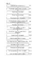
- FIG. 3 is a flow chart for explaining a manufacturing process of the Schottky barrier diode in FIG. 1 .
- FIG. 4A is a graph showing voltage-current characteristics at a time of a reverse bias with respect to three types of samples which have a structure of the first embodiment and whose respective epitaxial layer thicknesses are different.
- FIG. 4B is a graph showing voltage-current characteristics at a time of a reverse bias with respect to three types of samples which have a structure of a comparative example and whose respective epitaxial layer thicknesses are different.
- FIG. 5A is a graph showing a characteristic of a reverse pressure resistance with respect to an epitaxial layer thickness of the first embodiment.
- FIG. 5B is a graph showing a characteristic of a reverse pressure resistance with respect to an epitaxial layer thickness of the comparative example.
- FIG. 6 is a graph showing voltage-current characteristics at a time of a forward bias with respect to three types of samples which have the structure of the first embodiment and whose respective epitaxial layer thicknesses are different.
- FIG. 7 is a schematic plan view showing a Schottky barrier diode according to a second embodiment of the present invention.
- FIG. 8 is a sectional view along a line VIII-VIII in FIG. 7 .
- FIG. 9 is a flow chart for explaining a manufacturing process of the Schottky barrier diode in FIG. 7 .
- FIG. 10 is a schematic plan view showing a Schottky barrier diode according to a third embodiment of the present invention.
- FIG. 11 is a sectional view along a line XI-XI in FIG. 10 .
- FIG. 12 is a flow chart for explaining a manufacturing process of the Schottky barrier diode in FIG. 10 .
- FIG. 13 is a schematic plan view showing a Schottky barrier diode according to a fourth embodiment of the present invention.
- FIG. 14 is a sectional view along a line XIV-XIV in FIG. 13 .
- FIG. 15 is a schematic plan view showing a Schottky barrier diode according to a fifth embodiment of the present invention.
- FIG. 16 is a sectional view along a line XVI-XVI in FIG. 15 .
- FIG. 17 is a schematic plan view showing a Schottky barrier diode according to a sixth embodiment of the present invention.
- FIG. 18 is a sectional view along a line XVIII-XVIII in FIG. 17 .
- FIG. 1 is a plan view showing a Schottky barrier diode according to a first embodiment of the present invention.
- FIG. 2 is a sectional view along a line II-II in FIG. 1 .
- the Schottky barrier diode 1 is formed in a quadrangular chip shape in plan view, as shown in FIG. 1 , for example.
- Each length of four sides of the Schottky barrier diode 1 in plan view is several millimeters, for example.
- the Schottky barrier diode 1 comprises a semiconductor substrate 2 formed of n + -type (whose n-type impurity concentration is 1 ⁇ 10 18 to 1 ⁇ 10 21 cm ⁇ 3 , for example) silicone (Si).
- a cathode electrode 3 is formed on a rear surface of the semiconductor substrate 2 to cover an entire area thereof.
- the cathode electrode 3 is formed of a metal (Au, nickel (Ni) silicide and cobalt silicide, for example) which is brought into ohmic contact with an n-type silicone.
- An epitaxial layer 4 formed of an n ⁇ -type (whose n-type impurity concentration is 1 ⁇ 10 15 to 1 ⁇ 10 17 cm ⁇ 3 , for example) silicone with a concentration lower than that of the semiconductor substrate 2 is laminated on a front surface of the semiconductor substrate 2 .
- a thickness of the epitaxial layer 4 is 2 to 10 ⁇ m, for example.
- a field insulating film 5 formed of oxide silicon (SiO 2 ) is laminated on a surface of the epitaxial layer 4 .
- a thickness of the field insulating film 5 is, for example, 1,000 ⁇ or more, and is preferably 7,000 to 40,000 ⁇ .
- the field insulating film 5 may be formed of other insulator such as silicon nitride (SiN).
- the field insulating film 5 is provided with an opening 6 which exposes a center portion of the epitaxial layer 4 .
- An anode electrode 7 is formed on the field insulating film 5 .
- the anode electrode 7 is extended outside of the opening 6 in a flange shape to fill the opening 6 of the field insulating film 5 and cover a peripheral portion 8 of the opening 6 in the field insulating film 5 from above. That is, the peripheral portion 8 of the opening 6 in the field insulating film 5 is sandwiched from both of top and bottom sides thereof along an entire circumference by the epitaxial layer 4 and the anode electrode 7 .
- the anode electrode 7 has a multi-layer structure (two-layer structure in this embodiment) of a Schottky metal 9 joined to the epitaxial layer 4 in the opening 6 of the field insulating film 5 and an electrode metal 10 laminated on this Schottky metal 9 .
- the Schottky metal 9 is formed of a metal (titanium (Ti), molybdenum (Mo) and palladium (Pd), for example) forming Schottky-junction by joint with an n-type silicone.
- the Schottky metal 9 joined to the epitaxial layer 4 forms a Schottky barrier (potential barrier) of 0.52 to 0.9 eV, for example, in relation to a silicon semiconductor configuring the epitaxial layer 4 .
- a thickness of the Schottky metal 9 is, for example, 0.02 to 0.20 ⁇ m in this embodiment.
- the electrode metal 10 is a portion of the anode electrode 7 which is exposed on an outermost surface of the Schottky barrier diode 1 to be joined by a bonding wire and the like.
- the electrode metal 10 is formed of aluminum (Al), for example.
- a thickness of the electrode metal 10 is larger than that of the Schottky metal 9 , and is 0.5 to 5.0 ⁇ m, for example.
- the outermost surface of the Schottky barrier diode 1 is provided with a surface protection film 11 formed of SiN.
- a center portion of the surface protection film 11 is provided with an opening 12 which exposes the electrode metal 10 .
- a bonding wire or the like is joined to the electrode metal 10 via this opening 12 .
- a region of the surface of the epitaxial layer 4 where the Schottky metal 9 is in Schottky-contact with the surface of the epitaxial layer 4 is referred to as an active region 21 , and a region surrounding the active region 21 is referred to as a peripheral region 22 .
- a surface layer portion of the epitaxial layer 4 is provided with a peripheral trench 13 dug from the surface of the epitaxial layer 4 in a boundary portion between the active region 21 and the peripheral region 22 .
- the peripheral trench 13 has a circular shape (a quadrangular endless circle in this embodiment) in plan view, and is formed along a boundary of the active region 21 and the peripheral region 22 across the active region 21 and the peripheral region 22 .
- a bottom surface of the peripheral trench 13 includes a planar surface along the surface of the epitaxial layer 4 and a surface of the semiconductor substrate 2 . As a result, a section of the peripheral trench 13 has a generally rectangular shape.
- An entire area of inner wall surfaces (side surfaces and the bottom surface) of the peripheral trench 13 is provided with an insulating film 14 formed of oxide silicon (SiO 2 ), for example.
- a thickness of the insulating film 14 is 0.2 to 0.5 ⁇ m, for example.
- a conductor 15 which is connected to the Schottky metal 9 , is formed of polysilicon and is opposed to the entire area of the inner wall surfaces (including the side surfaces and the bottom surface) of the peripheral trench 13 via the insulating film 14 in the peripheral trench 13 .
- the conductor 15 may be provided in a manner to fill an empty portion in the peripheral trench 13 where the insulating film 14 is provided, or may be formed as a film along an inner surface of the insulating film 14 .
- This Schottky barrier diode 1 is a planar Schottky barrier diode where the surface of the epitaxial layer 4 in Schottky-contact with the Schottky metal 9 is planar.
- FIG. 3 is a process chart showing an example of a manufacturing process of the Schottky barrier diode 1 .
- an n + -type semiconductor wafer (not shown) as a source substrate of the semiconductor substrate 2 .
- a plurality of Schottky barrier diode regions corresponding to a plurality of Schottky barrier diodes 1 are set in a matrix arrangement on a surface of the semiconductor wafer.
- a boundary region (scribe line) is provided between adjacent Schottky barrier diodes.
- the boundary region is a band-shaped region having an approximately constant width, and is extended in two orthogonal directions to be formed in a lattice shape.
- the semiconductor wafer is cut off along the boundary region, whereby the plurality of Schottky barrier diodes 1 can be obtained. In this manner, a plurality of Schottky barrier diodes can be obtained from an n + -type semiconductor wafer also in second and third embodiments described below.
- an epitaxial layer 4 formed of n ⁇ -type silicone is developed on an n + -type silicon substrate (n + -type semiconductor wafer) 2 (step S 1 ).
- n + -type semiconductor wafer n + -type semiconductor wafer
- P or As can be used as an n-type impurity.
- step S 2 After a surface protecting thermally-oxidized film formed of SiO 2 is provided on a surface of the epitaxial layer 4 , an alignment mark is formed at a predetermined portion on a scribe line of the surface protecting thermally-oxidized film (step S 2 ).
- the alignment mark is used to align positions of a photomask and the wafer in following steps where photolithography is used.
- a hard mask formed of SiN and SiO 2 is provided by a CVD (Chemical Vapor Deposition) method, for example, on the surface protecting thermally-oxidized film (step S 3 ).
- the hard mask is patterned by a photography technique and an etching technique thereby to form the hard mask corresponding to a pattern of a peripheral trench 13 (step S 4 ). Then, the epitaxial layer 4 is etched through the hard mask thereby to form the peripheral trench 13 (step S 5 ).
- an insulating film 14 formed of SiO 2 is provided by thermal oxidation on an entire area of inner wall surfaces (including side surfaces and a bottom surface) of the peripheral trench 13 (step S 6 ).
- This insulating film 14 may be a combination of SiO 2 and PSG (Phosphorus Silicon Glass).
- step S 7 polysilicon is deposited by the CVD method, for example, until the peripheral trench 13 is filled and the entire surface of the epitaxial layer 4 is covered. Then, polysilicon is removed from outside of the peripheral trench 13 by etch back (step S 8 ).
- a field insulating film 5 formed of SiO 2 is provided on the epitaxial layer 4 (step S 9 ). Then, the field insulating film 5 and the surface protecting thermally-oxidized film are etched using as a mask a resist pattern (not shown) formed by photolithography, thereby to form an opening 6 which exposes a center portion (active region) of the epitaxial layer 4 and a portion of a conductor 15 in the peripheral trench 13 (step S 10 ).
- step S 11 Ti is deposited on surfaces of the epitaxial layer 4 and the field insulating film 5 by a sputtering method, for example, and this Ti layer is patterned by photolithography, thereby to form a Schottky metal 9 (step S 11 ).
- the Schottky metal 9 is formed in a manner to contact the conductor 15 and to cover an entire area of a surface of the epitaxial layer 4 in the opening 6 .
- Al is deposited on the Schottky metal 9 by the sputtering method, for example, and this Al layer is patterned by photolithography, thereby to form an electrode metal 10 (step S 12 ).
- an SiN layer is formed on surfaces of the electrode metal 10 and the field insulating film 5 by the CVD method, for example, and this SiN layer is patterned by photolithography, thereby to form a surface protection film 11 (step S 13 ).
- a cathode electrode 3 is formed on a rear surface of the n + -type silicon substrate 2 (step S 14 ). As a result, there can be obtained the Schottky barrier diode 1 as shown in FIGS. 1 and 2 .
- the peripheral trench 13 is formed on the boundary portion between the active region 21 and the peripheral region 22 , and the insulating film 14 is formed on the entire area of the inner wall surfaces of this peripheral trench 13 . Further, there is provided with a conductor 15 which is connected to the Schottky metal 9 and is opposed to the entire area of the inner wall surfaces of the peripheral trench 13 via the insulating film 14 in the peripheral trench 13 . That is, a field plate structure is formed on the boundary portion between the active region 21 and the peripheral region 22 . As a result, a portion immediately below the peripheral trench and outside of the side surfaces of the peripheral trench are depleted by field plate effect at a time of applying a reverse voltage. Therefore, concentration of an electric field can be alleviated on the boundary portion between the active region 21 and the peripheral region 22 .
- a thickness of a depletion layer formed immediately below the peripheral trench 13 can be thinned at the time of applying the reverse voltage in comparison to the structure of Patent Document 1 where a region of a conductivity type different from a conductivity type of an epitaxial layer is formed on a boundary portion between an active region 21 and a peripheral region 22 .
- the thickness of the epitaxial layer 4 can be thinned without significantly worsening a pressure resistance. Consequently, a resistance of the epitaxial layer 4 can be decreased without decreasing a specific resistance of the epitaxial layer 4 . Consequently, a forward voltage can be decreased without sacrificing a leakage current.
- a depth of the depletion layer formed immediately below the peripheral trench 13 can be made as approximately the same as a depth of a depletion layer formed in the active region 21 at the time of applying the reverse voltage, as shown by alternate long and short dash lines 30 in FIG. 2 .
- a lower end of a depletion layer formed in the epitaxial layer 4 can be made planar at the time of applying the reverse voltage, and therefore, the concentration of the electric field can be more effectively alleviated.
- a depth of a depletion layer formed immediately below the boundary portion between the active region 21 and the peripheral region 22 is larger than the depth of the depletion layer formed in the active region 21 at the time of applying the reverse voltage, as shown by alternate long and two short dashes lines 41 in FIG. 2 .
- characteristics of the Schottky barrier diode 1 of the first embodiment are compared to characteristics of a comparative example.
- a p-type region p-type guard ring
- the comparative example was used as the comparative example in place of the field plate structure comprising the peripheral trench 13 , the insulating film 14 and the conductor 15 in the Schottky barrier diode 1 shown in FIGS. 1 and 2 .
- FIG. 4A is a graph showing voltage-current characteristics (VR-IR characteristics) at a time of a reverse bias with respect to three types of samples which have a structure of the first embodiment and whose respective epitaxial layer thicknesses are different.
- FIG. 4B is a graph showing voltage-current characteristics (VR-IR characteristics) at a time of a reverse bias with respect to three types of samples which have a structure of a comparative example and whose respective epitaxial layer thicknesses are different.
- FIG. 4A shows VR-IR characteristics with respect to three types of samples where thicknesses of epitaxial layers 4 (hereinafter sometimes referred to as the “epitaxial layer thicknesses (Epi thicknesses)”) are respectively 2.4, 3.1 and 3.8 ⁇ m.
- Epi thicknesses epitaxial layers 4
- FIG. 4B shows VR-IR characteristics with respect to three types of samples where epitaxial layer thicknesses (Epi thicknesses) are respectively 3.2, 3.5 and 3.8 ⁇ m. It can be understood from FIG. 4A that in the first embodiment, leakage currents are not differentiated even when the epitaxial layer thicknesses are decreased.
- FIG. 5A is a graph showing a characteristic of a reverse pressure resistance (BV) with respect to an epitaxial layer thickness (Epi thickness) of the first embodiment.
- FIG. 5B is a graph showing a characteristic of a reverse pressure resistance (BV) with respect to an epitaxial layer thickness (Epi thickness) of the comparative example.
- the graph in FIG. 5A is made based on the VR-IR characteristics with respect to the three samples of FIG. 4A .
- the graph in FIG. 5B is made based on the VR-IR characteristics with respect to the three samples of FIG. 4B .
- a target value of the reverse pressure resistance is 57 V, for example.
- the comparative example requires an epitaxial layer thickness of 3.8 ⁇ m or more, while the first embodiment only requires an epitaxial layer thickness of 2.4 ⁇ m or more. That is, an epitaxial layer thickness required to obtain the targeted reverse pressure resistance is thinner in the first embodiment than in the comparative example.
- an epitaxial layer thickness can be made thinner in the first embodiment than in the comparative example, a resistance of the epitaxial layer 4 can be decreased without decreasing a specific resistance of the epitaxial layer 4 . Consequently, a forward voltage can be decreased without sacrificing a leakage current, and a Schottky barrier diode which easily ensures a required pressure resistance can be provided.
- FIG. 6 is a graph showing voltage-current characteristics (VR-IR characteristics) at a time of a forward bias with respect to three types of samples which have a structure of the first embodiment and whose respective epitaxial layer thicknesses are different. It can be understood from FIG. 6 that when an Epi thickness is made thin, a forward voltage is decreased in the first embodiment.
- FIG. 7 is a schematic plan view showing a Schottky barrier diode according to a second embodiment of the present invention.
- FIG. 8 is a sectional view along a line VIII-VIII in FIG. 7 . Portions in FIGS. 7 and 8 corresponding to the respective portions shown in above-described FIGS. 1 and 2 have the same reference symbols.
- a Schottky barrier diode 1 A of the second embodiment is different from the Schottky barrier diode 1 of the first embodiment in that a plurality of inside trenches 18 are formed in a surface layer portion of an epitaxial layer 4 on a region in an opening 6 of a field insulating film 5 , and in that a Schottky metal 9 is formed to contact a surface of the epitaxial layer 4 including inner wall surfaces of each inside trench 18 . That is, while the Schottky barrier diode 1 of the first embodiment is a planar Schottky barrier diode, the Schottky barrier diode 1 A of the second embodiment is a trench junction Schottky barrier diode.
- the plurality of inside trenches 18 are formed by digging the epitaxial layer 4 from the surface thereof on the surface layer portion of the epitaxial layer 4 in the region within the opening 6 of the field insulating film 5 .
- Each inside trench 18 is a longitudinal groove extending in a predetermined direction.
- a bottom surface of the inside trench 18 includes a planar surface along a surface of an n+-type silicon substrate 2 . Therefore, a section of each inside trench 18 has a generally rectangular shape.
- the plurality of inside trenches 18 are extended parallelly at a predetermined interval. Accordingly, these inside trenches 18 have a stripe shape in plan view.
- side surfaces of the inside trenches 18 may be approximately parallel to a normal line of the surface of the epitaxial layer 4 (thickness direction of the epitaxial layer 4 ).
- a surface area of the epitaxial layer 4 is larger by the side wall surfaces of the inside trenches 18 in comparison to a case where the inside trenches 18 are not formed.
- a mesa portion 19 is formed at a portion sandwiched by adjacent inside trenches 18 on the surface layer portion of the epitaxial layer 4 .
- the mesa portion 19 has accordingly a section of a generally rectangular shape.
- Each mesa portion 19 has a pair of side wall surfaces (side surfaces of the inside trench 18 ) which rise, for example, approximately vertically from respective one side edges of the bottom surface of an adjacent pair of inside trenches 18 , and has a top surface (the surface of the epitaxial layer 4 ) coupling these pair of side wall surfaces.
- the Schottky metal 9 is formed to contact the surface of the epitaxial layer 4 including the inner wall surfaces of the inside trench 18 (including the side surfaces and the bottom surface). Accordingly, the Schottky metal 9 is in contact with the surface of the epitaxial layer 4 on the inner wall surfaces of all the inside trenches 18 and outside of the inside trenches 18 . Further, the Schottky metal 9 covers an entire area of the inner wall surfaces of each inside trench 18 and extends continuously to outside of the inside trenches 18 . That is, the Schottky metal 9 is joined to the surface of the epitaxial layer 4 exposed from the opening 6 in a manner to cover an entire area thereof.
- the Schottky metal 9 includes a bottom surface portion contacting the bottom surface of the inside trench 18 , side surface portions contacting the side surfaces of the inside trench 18 (the side wall surfaces of the mesa portion 19 ), and a top surface portion contacting the top surface of the mesa portion 19 .
- a junction surface (a Schottky junction surface) S between the Schottky metal 9 and the surface of the epitaxial layer 4 is formed to have a concavo-convex section. Accordingly, a surface area of the Schottky junction surface S is larger than an apparent area of the epitaxial layer 4 in a plan view where the surface of the epitaxial layer 4 (a portion extending horizontally in FIG. 8 ) is looked down in the normal line thereof.
- the Schottky junction surface S includes a bottom surface portion S 1 contacting the bottom surface of the inside trench 18 , side surface portions S 2 contacting the side surfaces of the inside trench 18 (the side wall surfaces of the mesa portion 19 ), and a top surface portion S 3 contacting the top surface of the mesa portion 19 .
- the inside trenches 18 have a section of a generally rectangular shape, the area of the Schottky junction surface S can be increased by the side wall surfaces S 2 in comparison to a case where the inside trenches 18 are not formed.
- An electrode metal 10 is embedded in each inside trench 18 to contact the Schottky metal 9 covering the inner wall surfaces of each inside trench 18 .
- a surface of the electrode metal 10 opposite to aside contacting the Schottky metal 9 is planar along the surface of the epitaxial layer 4 (except the inner wall surfaces of the inside trench 18 ).
- a region where the Schottky metal 9 is in Schottky-contact with the surface of the epitaxial layer 4 is an active region 21
- a region which surrounds the active region 21 is a peripheral region 22 .
- a field plate structure comprising a peripheral trench 13 , an insulating film 14 and a conductor 15 is formed on a boundary portion between the active region 21 and the peripheral region 22 in the surface layer portion of the epitaxial layer 4 , similarly to the first embodiment.
- FIG. 9 is a process chart showing an example of a manufacturing process of the Schottky barrier diode 1 A.
- steps corresponding to the respective steps in FIG. 3 have the same step numbers as those in FIG. 3 .
- an epitaxial layer 4 formed of n ⁇ -type silicone is developed on an n + -type silicon substrate (n + -type semiconductor wafer) 2 (step S 1 ).
- a surface protecting thermally-oxidized film formed of SiO 2 is provided on a surface of the epitaxial layer 4 .
- the alignment mark is used to align positions of a photomask and a wafer in following steps where photolithography is used.
- a hard mask formed of SiN and SiO 2 is provided by the CVD method, for example, on the surface protecting thermally-oxidized film (step S 3 ).
- the hard mask is patterned by the photography technique and the etching technique thereby to form the hard mask corresponding to a pattern of a peripheral trench 13 (step S 4 ). Then, the epitaxial layer 4 is etched through the hard mask thereby to form the peripheral trench 13 (step S 5 ).
- an insulating film 14 formed of oxide silicon (SiO 2 ) is provided by thermal oxidation on an entire area of inner wall surfaces (side surfaces and a bottom surface) of the peripheral trench 13 (step S 6 ).
- step S 7 polysilicon is deposited by the CVD method, for example, until the peripheral trench 13 is filled and the entire surface of the epitaxial layer 4 is covered. Then, polysilicon is removed from outside of the peripheral trench 13 by etch back (step S 8 ).
- step S 21 a mask corresponding to a pattern of the inside trenches 18 by photography. Then, the inside trenches 18 are formed by etching the epitaxial layer 4 via this mask (step S 22 ).
- a field insulating film 5 formed of SiO 2 is provided on the epitaxial layer 4 (step S 9 ). Then, the field insulating film 5 and the surface protecting thermally-oxidized film are etched using as a mask a resist pattern (not shown) formed by photolithography, thereby to form an opening 6 which exposes a center portion (active region) of the epitaxial layer 4 and a portion of a conductor 15 in the peripheral trench 13 (step S 10 ).
- step S 11 Ti is deposited on surfaces of the epitaxial layer 4 and the field insulating film 5 by the sputtering method, for example, and this Ti layer is patterned by photolithography, thereby to form a Schottky metal 9 (step S 11 ).
- the Schottky metal 9 is formed in a manner to contact the conductor 15 and to cover an entire area of the surface of the epitaxial layer 4 in the opening 6 .
- Al is deposited on the Schottky metal 9 by the sputtering method, for example, and this Al layer is patterned by photolithography, thereby to form an electrode metal 10 (step S 12 ).
- an SiN layer is formed on surfaces of the electrode metal 10 and the field insulating film 5 by the CVD method, for example, and this SiN layer is patterned by photolithography, thereby to form a surface protection film 11 (step S 13 ).
- a cathode electrode 3 is formed on a rear surface of the n + -type silicon substrate 2 (step S 14 ). As a result, there can be obtained the Schottky barrier diode 1 A as shown in FIGS. 7 and 8 .
- FIG. 10 is a plan view showing a Schottky barrier diode according to a third embodiment of the present invention.
- FIG. 11 is a sectional view along a line XI-XI in FIG. 10 .
- Portions in FIGS. 10 and 11 corresponding to the respective portions shown in above-described FIGS. 1 and 2 have the same reference symbols.
- a Schottky barrier diode 1 B of the third embodiment is different from the Schottky barrier diode 1 of the first embodiment in that a field insulating film is not formed on a peripheral portion of an epitaxial layer 4 .
- an anode electrode 7 which is quadrangular in plan view is formed on a center region except a peripheral portion of a surface of the epitaxial layer 4 .
- the anode electrode 7 has a multi-layer structure (two-layer structure in this embodiment) of a Schottky metal 9 being in Schottky junction with the epitaxial layer 4 and an electrode metal 10 laminated on this Schottky metal 9 .
- An outermost surface of the Schottky barrier diode 1 B is provided with a surface protection film 11 formed of SiN.
- a center portion of the surface protection film 11 is provided with an opening 12 which exposes the electrode metal 10 .
- a region where the Schottky metal 9 is in Schottky-contact with the surface of the epitaxial layer 4 is an active region 21
- a region which surrounds the active region 21 is a peripheral region 22 .
- a field plate structure comprising a peripheral trench 13 , an insulating film 14 and a conductor 15 is formed on a boundary portion between the active region 21 and the peripheral region 22 in a surface layer portion of the epitaxial layer 4 , similarly to the first embodiment.
- FIG. 12 is a process chart showing an example of a manufacturing process of the Schottky barrier diode 1 B.
- steps corresponding to the respective steps in FIG. 3 have the same step numbers as those in FIG. 3 .
- an epitaxial layer 4 formed of n ⁇ -type silicone is developed on an n + -type silicon substrate 2 (step S 1 ).
- a surface protecting thermally-oxidized film formed of SiO 2 is provided on a surface of the epitaxial layer 4 (step S 2 ).
- a hard mask formed of SiN and SiO 2 is provided by the CVD method, for example, on the surface protecting thermally-oxidized film (step S 3 ).
- the hard mask is patterned by the photography technique and the etching technique thereby to form the hard mask corresponding to a pattern of a peripheral trench 13 and a pattern of an alignment mark (step S 4 A).
- the epitaxial layer 4 is etched through the hard mask thereby to form the peripheral trench 13 and the alignment mark (step S 5 A).
- the alignment mark is used to align positions of a photomask and a wafer in following steps where photolithography is used.
- an insulating film 14 formed of SiO 2 is provided by thermal oxidation on an entire area of inner wall surfaces (side surfaces and a bottom surface) of the peripheral trench 13 (step S 6 ).
- step S 7 polysilicon is deposited by the CVD method, for example, until the peripheral trench 13 is filled and the entire surface of the epitaxial layer 4 is covered. Then, polysilicon is removed from outside of the peripheral trench 13 by etch back (step S 8 ).
- step S 31 the surface protecting thermally-oxidized film is removed.
- Ti is deposited on the surface of the epitaxial layer 4 by the sputtering method, for example, and this Ti layer is patterned by photolithography, thereby to form a Schottky metal 9 (step S 11 A).
- the Schottky metal 9 is formed in a manner to contact the conductor 15 and to cover an entire area of the surface of the epitaxial layer 4 in a region surrounded by the peripheral trench 13 .
- Al is deposited on the Schottky metal 9 by the sputtering method, for example, and this Al layer is patterned by photolithography, thereby to form an electrode metal 10 (step S 12 A).
- an SiN layer is formed on surfaces of the electrode metal 10 and the epitaxial layer 4 by the CVD method, for example, and this SiN layer is patterned by photolithography, thereby to form a surface protection film 11 (step S 13 A).
- a cathode electrode 3 is formed on a rear surface of the n + -type silicon substrate 2 (step S 14 ). As a result, there can be obtained the Schottky barrier diode 1 B as shown in FIGS. 10 and 11 .
- FIG. 13 is a plan view showing a Schottky barrier diode according to a fourth embodiment of the present invention.
- FIG. 14 is a sectional view along a line XIV-XIV in FIG. 14 .
- Portions in FIGS. 13 and 14 corresponding to the respective portions shown in above-described FIGS. 1 and 2 have the same reference symbols.
- a Schottky barrier diode 1 C of the fourth embodiment is different from the Schottky barrier diode 1 of the first embodiment in that a peripheral trench 13 is configured from three peripheral trenches 13 A, 13 B and 13 C.
- the first peripheral trench 13 A, the second peripheral trench 13 B and the third peripheral trench 13 C dug from a surface of an epitaxial layer 4 are formed at a peripheral portion of the surface of the epitaxial layer 4 on a surface layer portion of the epitaxial layer 4 .
- Each of the peripheral trenches 13 A, 13 B and 13 C has a circular shape (a quadrangular endless circle in this embodiment) in plan view and is arranged at an interval.
- the first peripheral trench 13 A is arranged at an innermost portion.
- the third peripheral trench 13 C is arranged at an outermost portion.
- the second peripheral trench 13 B is arranged between the first peripheral trench 13 A and the third peripheral trench 13 C.
- a bottom surface of each of the peripheral trenches 13 A, 13 B and 13 C includes a planar surface along the surface of the epitaxial layer 4 and a surface of a semiconductor substrate 2 .
- a section of each of the peripheral trenches 13 A, 13 B and 13 C has a generally rectangular shape.
- An entire area of inner wall surfaces (side surfaces and the bottom surface) of each of the peripheral trenches 13 A, 13 B and 13 C is provided with an insulating film 14 formed of oxide silicon (SiO 2 ), for example.
- a conductor 15 which is formed of polysilicon and is opposed to the entire area of the inner wall surfaces (the side surfaces and the bottom surface) of each of the peripheral trenches 13 A, 13 B and 13 C via the insulating film 14 in each of the peripheral trenches 13 A, 13 B and 13 C.
- the conductor 15 may be provided in a manner to fill an empty portion in each of the peripheral trenches 13 A, 13 B and 13 C where the insulating film 14 is formed, or may be formed as a film along an inner surface of the insulating film 14 .
- An anode electrode 7 is formed to cover a region surrounded by the first peripheral trench 13 A on the surface of the epitaxial layer 4 , the insulating film 14 and the conductor 15 which are exposed in an opening of each of the peripheral trenches 13 A, 13 B and 13 C, the field insulating film 5 formed at the region between adjacent peripheral trenches, and an inner peripheral portion of the field insulating film 5 formed on the outer peripheral region of the third peripheral trench 13 C.
- the anode electrode 7 comprises a Schottky metal 9 which is in Schottky-contact with the surface of the epitaxial layer 4 and an electrode metal 10 laminated on this Schottky metal 9 .
- the Schottky metal 9 is joined to the region surrounded by the first peripheral trench 13 A on the surface of the epitaxial layer 4 , and is connected to the conductor 15 provided in each of the peripheral trenches 13 A, 13 B and 13 C.
- a surface of the electrode metal 10 opposite to a side contacting the Schottky metal 9 is planar along the surface of the epitaxial layer 4 .
- An outermost surface of the Schottky barrier diode 1 C is provided with a surface protection film 11 formed of SiN.
- a center portion of the surface protection film 11 is provided with an opening 12 which exposes the electrode metal 10 .
- a region where the Schottky metal 9 is in Schottky-contact with the surface of the epitaxial layer 4 is an active region 21
- a region surrounding the active region 21 is a peripheral region 22 .
- a field plate structure comprising the peripheral trenches 13 A, 13 B and 13 C, the insulating film 14 and the conductor 15 is formed at a boundary portion between the active region 21 and the peripheral region 22 on the surface layer portion of the epitaxial layer 4 , similarly to the first embodiment.
- FIG. 15 is a schematic plan view showing a Schottky barrier diode according to a fifth embodiment of the present invention.
- FIG. 16 is a sectional view along a line XVI-XVI in FIG. 15 . Portions in FIGS. 15 and 16 corresponding to the respective portions shown in above-described FIGS. 1 and 2 have the same reference symbols.
- a Schottky barrier diode 1 D of the fifth embodiment is different from the Schottky barrier diode 1 of the first embodiment in that a plurality of inside trenches 18 are formed on a surface layer portion of an epitaxial layer 4 in a region within an opening 6 of a field insulating film 5 , an oxide film 31 is formed on inner wall surfaces (side surfaces and a bottom surface) of each of these inside trenches 18 , and polysilicon 32 is embedded in each of the inside trenches 18 to contact the oxide film 31 . That is, while the Schottky barrier diode 1 of the first embodiment is a planar Schottky barrier diode, the Schottky barrier diode 1 D of the fifth embodiment is a trench MOS Schottky barrier diode.
- the plurality of inside trenches 18 are formed by digging the epitaxial layer 4 from the surface thereof on the surface layer portion of the epitaxial layer 4 in the region within the opening 6 of the field insulating film 5 .
- Each inside trench 18 is a longitudinal groove extending in a predetermined direction.
- a bottom surface of the inside trench 18 includes a planar surface along a surface of an n + -type silicon substrate 2 . Therefore, a section of each inside trench 18 has a generally rectangular shape.
- the plurality of inside trenches 18 are extended parallelly at a predetermined interval. Accordingly, these inside trenches 18 have a stripe shape in plan view.
- side surfaces of the inside trenches 18 may be approximately parallel to a normal line of the surface of the epitaxial layer 4 (thickness direction of the epitaxial layer 4 ).
- the oxide film 31 is formed on the inner wall surfaces (the side surfaces and the bottom surface) of each inside trench 18 .
- the polysilicon 32 is embedded in the inside trench 18 to contact the oxide film 31 .
- An anode electrode 7 is extended outside of the opening 6 in a flange shape to fill the opening 6 of the field insulating film 5 and cover a peripheral portion 8 of the opening 6 in the field insulating film 5 from above.
- the anode electrode 7 comprises a Schottky metal 9 which is in Schottky-contact with the surface of the epitaxial layer 4 and an electrode metal 10 laminated on this Schottky metal 9 .
- the Schottky metal 9 is joined to the surface of the epitaxial layer 4 outside the inside and peripheral trenches 18 and 13 in the region within the opening 6 of the field insulating film 5 , and at the same time, is connected to the polysilicon 32 in the inside trench 18 and a conductor 15 in the peripheral trench 13 .
- a surface of the electrode metal 10 opposite to a side contacting the Schottky metal 9 is planar along the surface of the epitaxial layer 4 (except the inner wall surfaces of the inside trench 18 ).
- a region where the Schottky metal 9 is in Schottky-contact with the surface of the epitaxial layer 4 is an active region 21
- a region which surrounds the active region 21 is a peripheral region 22 .
- a field plate structure comprising the peripheral trench 13 , the insulating film 14 and the conductor 15 is formed on a boundary portion between the active region 21 and the peripheral region 22 in the surface layer portion of the epitaxial layer 4 , similarly to the first embodiment.
- FIG. 17 is a plan view showing a Schottky barrier diode according to a sixth embodiment of the present invention.
- FIG. 18 is a sectional view along a line XVIII-XVIII in FIG. 17 .
- Portions in FIGS. 17 and 18 corresponding to the respective portions shown in above-described FIGS. 1 and 2 have the same reference symbols.
- a Schottky barrier diode 1 E of the sixth embodiment is similar to the above-described Schottky barrier diode 1 D of the fifth embodiment (see FIGS. 15 and 16 ). That is, the Schottky barrier diode 1 E of the sixth embodiment is a trench MOS Schottky barrier diode.
- the Schottky barrier diode 1 E of the sixth embodiment is different from the Schottky barrier diode 1 D of the fifth embodiment in that a peripheral trench 13 is configured from three peripheral trenches 13 A, 13 B and 13 C.
- the first peripheral trench 13 A, the second peripheral trench 13 B and the third peripheral trench 13 C dug from a surface of an epitaxial layer 4 are formed at a peripheral portion of the surface of the epitaxial layer 4 on a surface layer portion of the epitaxial layer 4 .
- Each of the peripheral trenches 13 A, 13 B and 13 C has a circular shape (a quadrangular endless circle in this embodiment) in plan view and is arranged at an interval.
- the first peripheral trench 13 A is arranged at an innermost portion.
- the third peripheral trench 13 C is arranged at an outermost portion.
- the second peripheral trench 13 B is arranged between the first peripheral trench 13 A and the third peripheral trench 13 C.
- a bottom surface of each of the peripheral trenches 13 A, 13 B and 13 C includes a planar surface along the surface of the epitaxial layer 4 and a surface of a semiconductor substrate 2 .
- a section of each of the peripheral trenches 13 A, 13 B and 13 C has a generally rectangular shape.
- An entire area of inner wall surfaces (side surfaces and the bottom surface) of each of the peripheral trenches 13 A, 13 B and 13 C is provided with an insulating film 14 formed of oxide silicon (SiO 2 ), for example.
- a conductor 15 which is formed of polysilicon and is opposed to the entire area of the inner wall surfaces (the side surfaces and the bottom surface) of each of the peripheral trenches 13 A, 13 B and 13 C via the insulating film 14 in each of the peripheral trenches 13 A, 13 B and 13 C.
- the conductor 15 may be provided in a manner to fill an empty portion in each of the peripheral trenches 13 A, 13 B and 13 C where the insulating film 14 is formed, or may be formed as a film along an inner surface of the insulating film 14 .
- a plurality of inside trenches 18 are formed on the surface layer portion of the epitaxial layer 4 in a region surrounded by the first peripheral trench 13 A, an oxide film 31 is formed on inner wall surfaces (side surfaces and a bottom surface) of each of these inside trenches 18 , and a polysilicon 32 is embedded in each of the inside trenches 18 to contact this oxide film 31 .
- An anode electrode 7 is formed to cover the oxide film 31 and polysilicon 32 which are exposed in an opening of the inside trench 18 , the surface of the epitaxial layer 4 outside the inside trench 18 in a region surrounded by the first peripheral trench 13 A, the insulating film 14 and the conductor 15 which are exposed in an opening of each of the peripheral trenches 13 A, 13 B and 13 C, the field insulating film 5 formed at the region between adjacent peripheral trenches, and an inner peripheral portion of the field insulating film 5 formed on an outer peripheral region of the third peripheral trench 13 C.
- the anode electrode 7 comprises a Schottky metal 9 which is in Schottky-contact with the surface of the epitaxial layer 4 and an electrode metal 10 laminated on this Schottky metal 9 .
- the Schottky metal 9 is joined to the surface of the epitaxial layer 4 outside the inside trench 18 in the region surrounded by the first peripheral trench 13 A, and at the same time, is connected to the polysilicon 32 in the inside trench 18 and the conductor 15 in each of the peripheral trenches 13 A, 13 B and 13 C.
- a surface of the electrode metal 10 opposite to a side contacting the Schottky metal 9 is planar along the surface of the epitaxial layer 4 (except the inner wall surfaces of the inside trench 18 ).
- An outermost surface of the Schottky barrier diode 1 E is provided with a surface protection film 11 formed of SiN.
- a center portion of the surface protection film 11 is provided with an opening 12 which exposes the electrode metal 10 .
- a region where the Schottky metal 9 is in Schottky-contact with the surface of the epitaxial layer 4 is an active region 21
- a region surrounding the active region 21 is a peripheral region 22 .
- a field plate structure comprising the peripheral trenches 13 A, 13 B and 13 C, the insulating film 14 and the conductor 15 is formed at a boundary portion between the active region 21 and the peripheral region 22 on the surface layer portion of the epitaxial layer 4 , similarly to the first embodiment.
- the conductor 15 is polysilicon in the above first to sixth embodiments, the conductor 15 may be a metal used for the Schottky metal 9 (titanium (Ti), molybdenum (Mo), palladium (Pd), for example) and a metal used for the electrode metal 10 (aluminum (Al), for example).
- the Schottky metal 9 titanium (Ti), molybdenum (Mo), palladium (Pd), for example
- a metal used for the electrode metal 10 aluminum (Al), for example).
- the semiconductor substrate 2 is not limited to a semiconductor substrate formed of silicone, but may be a semiconductor other than silicone.
- the impurity concentration of the semiconductor substrate 2 is an example, and a suitable value can be appropriately selected and used.
- the epitaxial layer 4 is not limited to an epitaxial layer formed of silicone, but may be an epitaxial layer other than silicone.
- the impurity concentration and thickness of the epitaxial layer 4 are examples, and suitable values can be appropriately selected and used.
- a suitable material can be appropriately selected and used for a material of the insulating film 14 .
- the thickness of the insulating film 14 is an example, and a suitable value can be appropriately selected and used.
- the anode electrode 7 has a two-layer structure of the Schottky metal 9 and the electrode metal 10
- the anode electrode 7 may have a one-layer structure or a three or more-layer structure.
- a suitable material can be appropriately selected and used for a material of the Schottky metal 9 and the electrode metal 10 .
- the thicknesses of the Schottky metal 9 and the electrode metal 10 are examples, and suitable values can be appropriately selected and used.
- the depth of the depletion layer formed immediately below the peripheral trench 13 at the time of applying the reverse voltage is not larger than the depth of the depletion layer formed in the active region 21 .
- a p-type portion may be n-type, and an n-type portion may be p-type.
Priority Applications (1)
| Application Number | Priority Date | Filing Date | Title |
|---|---|---|---|
| US15/711,655 US20180013015A1 (en) | 2014-02-10 | 2017-09-21 | Schottky barrier diode and a method of manufacturing the same |
Applications Claiming Priority (2)
| Application Number | Priority Date | Filing Date | Title |
|---|---|---|---|
| JP2014023571A JP6296445B2 (ja) | 2014-02-10 | 2014-02-10 | ショットキーバリアダイオード |
| JP2014-023571 | 2014-02-10 |
Related Child Applications (1)
| Application Number | Title | Priority Date | Filing Date |
|---|---|---|---|
| US15/711,655 Continuation US20180013015A1 (en) | 2014-02-10 | 2017-09-21 | Schottky barrier diode and a method of manufacturing the same |
Publications (2)
| Publication Number | Publication Date |
|---|---|
| US20150228809A1 US20150228809A1 (en) | 2015-08-13 |
| US9793418B2 true US9793418B2 (en) | 2017-10-17 |
Family
ID=53775698
Family Applications (2)
| Application Number | Title | Priority Date | Filing Date |
|---|---|---|---|
| US14/615,008 Active US9793418B2 (en) | 2014-02-10 | 2015-02-05 | Schottky barrier diode |
| US15/711,655 Abandoned US20180013015A1 (en) | 2014-02-10 | 2017-09-21 | Schottky barrier diode and a method of manufacturing the same |
Family Applications After (1)
| Application Number | Title | Priority Date | Filing Date |
|---|---|---|---|
| US15/711,655 Abandoned US20180013015A1 (en) | 2014-02-10 | 2017-09-21 | Schottky barrier diode and a method of manufacturing the same |
Country Status (2)
| Country | Link |
|---|---|
| US (2) | US9793418B2 (ja) |
| JP (1) | JP6296445B2 (ja) |
Families Citing this family (13)
| Publication number | Priority date | Publication date | Assignee | Title |
|---|---|---|---|---|
| JP6222771B2 (ja) * | 2013-11-22 | 2017-11-01 | 国立研究開発法人産業技術総合研究所 | 炭化珪素半導体装置の製造方法 |
| JP7433611B2 (ja) * | 2016-04-28 | 2024-02-20 | 株式会社タムラ製作所 | トレンチmos型ショットキーダイオード |
| JP7147141B2 (ja) * | 2017-09-11 | 2022-10-05 | Tdk株式会社 | ショットキーバリアダイオード |
| CN107946351B (zh) * | 2017-09-20 | 2023-09-12 | 重庆中科渝芯电子有限公司 | 一种肖特基接触超级势垒整流器及其制作方法 |
| JP7045008B2 (ja) * | 2017-10-26 | 2022-03-31 | Tdk株式会社 | ショットキーバリアダイオード |
| CN108336152A (zh) * | 2018-03-20 | 2018-07-27 | 重庆大学 | 具有浮动结的沟槽型碳化硅sbd器件及其制造方法 |
| JP6626929B1 (ja) | 2018-06-29 | 2019-12-25 | 京セラ株式会社 | 半導体デバイス及び電気装置 |
| JP2020141086A (ja) * | 2019-03-01 | 2020-09-03 | 京セラ株式会社 | 半導体装置及び半導体装置の製造方法 |
| CN110047944A (zh) * | 2019-04-25 | 2019-07-23 | 江阴新顺微电子有限公司 | 一种低成本的tmbs器件结构及制造方法 |
| JP7371484B2 (ja) * | 2019-12-18 | 2023-10-31 | Tdk株式会社 | ショットキーバリアダイオード |
| JP7415537B2 (ja) * | 2019-12-18 | 2024-01-17 | Tdk株式会社 | ショットキーバリアダイオード |
| CN113471301B (zh) * | 2020-03-31 | 2023-10-17 | 比亚迪半导体股份有限公司 | 一种沟槽肖特基二极管及其制备方法 |
| CN113903813B (zh) * | 2021-09-30 | 2024-02-09 | 上海芯导电子科技股份有限公司 | 肖特基二极管及其制备方法、电子设备 |
Citations (8)
| Publication number | Priority date | Publication date | Assignee | Title |
|---|---|---|---|---|
| JPH09283771A (ja) | 1996-04-12 | 1997-10-31 | Fuji Electric Co Ltd | ショットキーバリアダイオード |
| JP2002217426A (ja) | 2000-09-22 | 2002-08-02 | General Semiconductor Inc | 終端構造及びトレンチ金属酸化膜半導体素子 |
| JP2008300506A (ja) | 2007-05-30 | 2008-12-11 | Denso Corp | ジャンクションバリアショットキーダイオードを備えた炭化珪素半導体装置 |
| JP2010123741A (ja) | 2008-11-19 | 2010-06-03 | Showa Denko Kk | 半導体装置および半導体装置の製造方法 |
| JP2011142123A (ja) | 2010-01-05 | 2011-07-21 | Fuji Electric Co Ltd | 半導体装置 |
| US20110227151A1 (en) | 2010-03-16 | 2011-09-22 | Vishay General Semiconductor Llc | Trench dmos device with improved termination structure for high voltage applications |
| JP2012023199A (ja) | 2010-07-14 | 2012-02-02 | Rohm Co Ltd | ショットキバリアダイオード |
| US20120146055A1 (en) * | 2010-12-08 | 2012-06-14 | Rohm Co., Ltd. | SiC SEMICONDUCTOR DEVICE |
Family Cites Families (3)
| Publication number | Priority date | Publication date | Assignee | Title |
|---|---|---|---|---|
| JP5541842B2 (ja) * | 2008-03-18 | 2014-07-09 | 新電元工業株式会社 | 炭化珪素ショットキダイオード |
| WO2012105611A1 (ja) * | 2011-02-02 | 2012-08-09 | ローム株式会社 | 半導体パワーデバイスおよびその製造方法 |
| JP5928101B2 (ja) * | 2012-03-30 | 2016-06-01 | 富士電機株式会社 | SiC半導体デバイスの製造方法 |
-
2014
- 2014-02-10 JP JP2014023571A patent/JP6296445B2/ja active Active
-
2015
- 2015-02-05 US US14/615,008 patent/US9793418B2/en active Active
-
2017
- 2017-09-21 US US15/711,655 patent/US20180013015A1/en not_active Abandoned
Patent Citations (8)
| Publication number | Priority date | Publication date | Assignee | Title |
|---|---|---|---|---|
| JPH09283771A (ja) | 1996-04-12 | 1997-10-31 | Fuji Electric Co Ltd | ショットキーバリアダイオード |
| JP2002217426A (ja) | 2000-09-22 | 2002-08-02 | General Semiconductor Inc | 終端構造及びトレンチ金属酸化膜半導体素子 |
| JP2008300506A (ja) | 2007-05-30 | 2008-12-11 | Denso Corp | ジャンクションバリアショットキーダイオードを備えた炭化珪素半導体装置 |
| JP2010123741A (ja) | 2008-11-19 | 2010-06-03 | Showa Denko Kk | 半導体装置および半導体装置の製造方法 |
| JP2011142123A (ja) | 2010-01-05 | 2011-07-21 | Fuji Electric Co Ltd | 半導体装置 |
| US20110227151A1 (en) | 2010-03-16 | 2011-09-22 | Vishay General Semiconductor Llc | Trench dmos device with improved termination structure for high voltage applications |
| JP2012023199A (ja) | 2010-07-14 | 2012-02-02 | Rohm Co Ltd | ショットキバリアダイオード |
| US20120146055A1 (en) * | 2010-12-08 | 2012-06-14 | Rohm Co., Ltd. | SiC SEMICONDUCTOR DEVICE |
Also Published As
| Publication number | Publication date |
|---|---|
| JP6296445B2 (ja) | 2018-03-20 |
| JP2015153769A (ja) | 2015-08-24 |
| US20180013015A1 (en) | 2018-01-11 |
| US20150228809A1 (en) | 2015-08-13 |
Similar Documents
| Publication | Publication Date | Title |
|---|---|---|
| US9793418B2 (en) | Schottky barrier diode | |
| US10559658B2 (en) | Schottky barrier diode | |
| JP6241572B2 (ja) | 半導体装置 | |
| JP2019165206A (ja) | 絶縁ゲート型半導体装置及びその製造方法 | |
| JP6411258B2 (ja) | 半導体装置 | |
| TW201011822A (en) | Semiconductor device and method of producing the same | |
| US9236431B2 (en) | Semiconductor device and termination region structure thereof | |
| JP2009267032A (ja) | 半導体装置とその製造方法 | |
| JP6484304B2 (ja) | ショットキバリアダイオード | |
| WO2017187856A1 (ja) | 半導体装置 | |
| TWI750875B (zh) | 肖特基能障二極體 | |
| TWI608617B (zh) | 半導體裝置及其製造方法 | |
| WO2021124650A1 (ja) | ショットキーバリアダイオード | |
| JP6293380B1 (ja) | 半導体装置 | |
| JP2005005486A (ja) | 炭化けい素半導体装置 | |
| JP7159949B2 (ja) | 半導体装置 | |
| TWI688100B (zh) | 寬帶隙半導體裝置 | |
| JP6200107B1 (ja) | ワイドギャップ型半導体装置 | |
| JP4957050B2 (ja) | 半導体装置およびその製造方法 | |
| TWI837700B (zh) | 合併PiN蕭特基(MPS)二極體與其製造方法 | |
| JP7113386B2 (ja) | 半導体装置 | |
| CN117790583A (zh) | 碳化硅半导体装置 | |
| JP2016096351A (ja) | ショットキバリアダイオード |
Legal Events
| Date | Code | Title | Description |
|---|---|---|---|
| AS | Assignment |
Owner name: ROHM CO., LTD., JAPAN Free format text: ASSIGNMENT OF ASSIGNORS INTEREST;ASSIGNOR:SUGIURA, HIROTO;REEL/FRAME:035449/0105 Effective date: 20150402 |
|
| STCF | Information on status: patent grant |
Free format text: PATENTED CASE |
|
| MAFP | Maintenance fee payment |
Free format text: PAYMENT OF MAINTENANCE FEE, 4TH YEAR, LARGE ENTITY (ORIGINAL EVENT CODE: M1551); ENTITY STATUS OF PATENT OWNER: LARGE ENTITY Year of fee payment: 4 |