JP6245107B2 - 半導体装置及び半導体装置の製造方法 - Google Patents
半導体装置及び半導体装置の製造方法 Download PDFInfo
- Publication number
- JP6245107B2 JP6245107B2 JP2014160719A JP2014160719A JP6245107B2 JP 6245107 B2 JP6245107 B2 JP 6245107B2 JP 2014160719 A JP2014160719 A JP 2014160719A JP 2014160719 A JP2014160719 A JP 2014160719A JP 6245107 B2 JP6245107 B2 JP 6245107B2
- Authority
- JP
- Japan
- Prior art keywords
- insulating film
- contact
- semiconductor
- semiconductor substrate
- trench
- Prior art date
- Legal status (The legal status is an assumption and is not a legal conclusion. Google has not performed a legal analysis and makes no representation as to the accuracy of the status listed.)
- Active
Links
- 239000004065 semiconductor Substances 0.000 title claims description 189
- 238000004519 manufacturing process Methods 0.000 title claims description 16
- 239000010410 layer Substances 0.000 claims description 139
- 239000000758 substrate Substances 0.000 claims description 83
- 239000004020 conductor Substances 0.000 claims description 69
- 239000011229 interlayer Substances 0.000 claims description 48
- 238000005530 etching Methods 0.000 claims description 7
- 238000000034 method Methods 0.000 claims description 7
- 229910052782 aluminium Inorganic materials 0.000 claims description 5
- 229910052721 tungsten Inorganic materials 0.000 claims description 5
- 238000007747 plating Methods 0.000 claims description 4
- 238000004544 sputter deposition Methods 0.000 claims description 4
- 229910052802 copper Inorganic materials 0.000 claims description 3
- 239000000463 material Substances 0.000 claims description 3
- 229910052751 metal Inorganic materials 0.000 claims description 2
- 239000002184 metal Substances 0.000 claims description 2
- 210000000746 body region Anatomy 0.000 description 16
- 239000012535 impurity Substances 0.000 description 9
- 238000011084 recovery Methods 0.000 description 5
- 238000005516 engineering process Methods 0.000 description 3
- XAGFODPZIPBFFR-UHFFFAOYSA-N aluminium Chemical compound [Al] XAGFODPZIPBFFR-UHFFFAOYSA-N 0.000 description 2
- 230000015572 biosynthetic process Effects 0.000 description 2
- WFKWXMTUELFFGS-UHFFFAOYSA-N tungsten Chemical compound [W] WFKWXMTUELFFGS-UHFFFAOYSA-N 0.000 description 2
- 239000010937 tungsten Substances 0.000 description 2
- XUIMIQQOPSSXEZ-UHFFFAOYSA-N Silicon Chemical compound [Si] XUIMIQQOPSSXEZ-UHFFFAOYSA-N 0.000 description 1
- 229910045601 alloy Inorganic materials 0.000 description 1
- 239000000956 alloy Substances 0.000 description 1
- 230000015556 catabolic process Effects 0.000 description 1
- 239000012141 concentrate Substances 0.000 description 1
- 230000005684 electric field Effects 0.000 description 1
- 238000009413 insulation Methods 0.000 description 1
- 239000012212 insulator Substances 0.000 description 1
- 238000012986 modification Methods 0.000 description 1
- 230000004048 modification Effects 0.000 description 1
- 230000002250 progressing effect Effects 0.000 description 1
- 229910052710 silicon Inorganic materials 0.000 description 1
- 239000010703 silicon Substances 0.000 description 1
- 229910000679 solder Inorganic materials 0.000 description 1
Images


Classifications
-
- H—ELECTRICITY
- H01—ELECTRIC ELEMENTS
- H01L—SEMICONDUCTOR DEVICES NOT COVERED BY CLASS H10
- H01L27/00—Devices consisting of a plurality of semiconductor or other solid-state components formed in or on a common substrate
- H01L27/02—Devices consisting of a plurality of semiconductor or other solid-state components formed in or on a common substrate including semiconductor components specially adapted for rectifying, oscillating, amplifying or switching and having at least one potential-jump barrier or surface barrier; including integrated passive circuit elements with at least one potential-jump barrier or surface barrier
- H01L27/04—Devices consisting of a plurality of semiconductor or other solid-state components formed in or on a common substrate including semiconductor components specially adapted for rectifying, oscillating, amplifying or switching and having at least one potential-jump barrier or surface barrier; including integrated passive circuit elements with at least one potential-jump barrier or surface barrier the substrate being a semiconductor body
- H01L27/06—Devices consisting of a plurality of semiconductor or other solid-state components formed in or on a common substrate including semiconductor components specially adapted for rectifying, oscillating, amplifying or switching and having at least one potential-jump barrier or surface barrier; including integrated passive circuit elements with at least one potential-jump barrier or surface barrier the substrate being a semiconductor body including a plurality of individual components in a non-repetitive configuration
- H01L27/07—Devices consisting of a plurality of semiconductor or other solid-state components formed in or on a common substrate including semiconductor components specially adapted for rectifying, oscillating, amplifying or switching and having at least one potential-jump barrier or surface barrier; including integrated passive circuit elements with at least one potential-jump barrier or surface barrier the substrate being a semiconductor body including a plurality of individual components in a non-repetitive configuration the components having an active region in common
- H01L27/0705—Devices consisting of a plurality of semiconductor or other solid-state components formed in or on a common substrate including semiconductor components specially adapted for rectifying, oscillating, amplifying or switching and having at least one potential-jump barrier or surface barrier; including integrated passive circuit elements with at least one potential-jump barrier or surface barrier the substrate being a semiconductor body including a plurality of individual components in a non-repetitive configuration the components having an active region in common comprising components of the field effect type
- H01L27/0711—Devices consisting of a plurality of semiconductor or other solid-state components formed in or on a common substrate including semiconductor components specially adapted for rectifying, oscillating, amplifying or switching and having at least one potential-jump barrier or surface barrier; including integrated passive circuit elements with at least one potential-jump barrier or surface barrier the substrate being a semiconductor body including a plurality of individual components in a non-repetitive configuration the components having an active region in common comprising components of the field effect type in combination with bipolar transistors and diodes, or capacitors, or resistors
- H01L27/0716—Devices consisting of a plurality of semiconductor or other solid-state components formed in or on a common substrate including semiconductor components specially adapted for rectifying, oscillating, amplifying or switching and having at least one potential-jump barrier or surface barrier; including integrated passive circuit elements with at least one potential-jump barrier or surface barrier the substrate being a semiconductor body including a plurality of individual components in a non-repetitive configuration the components having an active region in common comprising components of the field effect type in combination with bipolar transistors and diodes, or capacitors, or resistors in combination with vertical bipolar transistors and diodes, or capacitors, or resistors
-
- H—ELECTRICITY
- H01—ELECTRIC ELEMENTS
- H01L—SEMICONDUCTOR DEVICES NOT COVERED BY CLASS H10
- H01L27/00—Devices consisting of a plurality of semiconductor or other solid-state components formed in or on a common substrate
- H01L27/02—Devices consisting of a plurality of semiconductor or other solid-state components formed in or on a common substrate including semiconductor components specially adapted for rectifying, oscillating, amplifying or switching and having at least one potential-jump barrier or surface barrier; including integrated passive circuit elements with at least one potential-jump barrier or surface barrier
- H01L27/04—Devices consisting of a plurality of semiconductor or other solid-state components formed in or on a common substrate including semiconductor components specially adapted for rectifying, oscillating, amplifying or switching and having at least one potential-jump barrier or surface barrier; including integrated passive circuit elements with at least one potential-jump barrier or surface barrier the substrate being a semiconductor body
- H01L27/06—Devices consisting of a plurality of semiconductor or other solid-state components formed in or on a common substrate including semiconductor components specially adapted for rectifying, oscillating, amplifying or switching and having at least one potential-jump barrier or surface barrier; including integrated passive circuit elements with at least one potential-jump barrier or surface barrier the substrate being a semiconductor body including a plurality of individual components in a non-repetitive configuration
- H01L27/07—Devices consisting of a plurality of semiconductor or other solid-state components formed in or on a common substrate including semiconductor components specially adapted for rectifying, oscillating, amplifying or switching and having at least one potential-jump barrier or surface barrier; including integrated passive circuit elements with at least one potential-jump barrier or surface barrier the substrate being a semiconductor body including a plurality of individual components in a non-repetitive configuration the components having an active region in common
- H01L27/0705—Devices consisting of a plurality of semiconductor or other solid-state components formed in or on a common substrate including semiconductor components specially adapted for rectifying, oscillating, amplifying or switching and having at least one potential-jump barrier or surface barrier; including integrated passive circuit elements with at least one potential-jump barrier or surface barrier the substrate being a semiconductor body including a plurality of individual components in a non-repetitive configuration the components having an active region in common comprising components of the field effect type
- H01L27/0727—Devices consisting of a plurality of semiconductor or other solid-state components formed in or on a common substrate including semiconductor components specially adapted for rectifying, oscillating, amplifying or switching and having at least one potential-jump barrier or surface barrier; including integrated passive circuit elements with at least one potential-jump barrier or surface barrier the substrate being a semiconductor body including a plurality of individual components in a non-repetitive configuration the components having an active region in common comprising components of the field effect type in combination with diodes, or capacitors or resistors
-
- H—ELECTRICITY
- H01—ELECTRIC ELEMENTS
- H01L—SEMICONDUCTOR DEVICES NOT COVERED BY CLASS H10
- H01L21/00—Processes or apparatus adapted for the manufacture or treatment of semiconductor or solid state devices or of parts thereof
- H01L21/70—Manufacture or treatment of devices consisting of a plurality of solid state components formed in or on a common substrate or of parts thereof; Manufacture of integrated circuit devices or of parts thereof
- H01L21/71—Manufacture of specific parts of devices defined in group H01L21/70
- H01L21/768—Applying interconnections to be used for carrying current between separate components within a device comprising conductors and dielectrics
-
- H—ELECTRICITY
- H01—ELECTRIC ELEMENTS
- H01L—SEMICONDUCTOR DEVICES NOT COVERED BY CLASS H10
- H01L21/00—Processes or apparatus adapted for the manufacture or treatment of semiconductor or solid state devices or of parts thereof
- H01L21/70—Manufacture or treatment of devices consisting of a plurality of solid state components formed in or on a common substrate or of parts thereof; Manufacture of integrated circuit devices or of parts thereof
- H01L21/77—Manufacture or treatment of devices consisting of a plurality of solid state components or integrated circuits formed in, or on, a common substrate
- H01L21/78—Manufacture or treatment of devices consisting of a plurality of solid state components or integrated circuits formed in, or on, a common substrate with subsequent division of the substrate into plural individual devices
- H01L21/82—Manufacture or treatment of devices consisting of a plurality of solid state components or integrated circuits formed in, or on, a common substrate with subsequent division of the substrate into plural individual devices to produce devices, e.g. integrated circuits, each consisting of a plurality of components
- H01L21/822—Manufacture or treatment of devices consisting of a plurality of solid state components or integrated circuits formed in, or on, a common substrate with subsequent division of the substrate into plural individual devices to produce devices, e.g. integrated circuits, each consisting of a plurality of components the substrate being a semiconductor, using silicon technology
- H01L21/8248—Combination of bipolar and field-effect technology
- H01L21/8249—Bipolar and MOS technology
-
- H—ELECTRICITY
- H01—ELECTRIC ELEMENTS
- H01L—SEMICONDUCTOR DEVICES NOT COVERED BY CLASS H10
- H01L23/00—Details of semiconductor or other solid state devices
- H01L23/52—Arrangements for conducting electric current within the device in operation from one component to another, i.e. interconnections, e.g. wires, lead frames
- H01L23/522—Arrangements for conducting electric current within the device in operation from one component to another, i.e. interconnections, e.g. wires, lead frames including external interconnections consisting of a multilayer structure of conductive and insulating layers inseparably formed on the semiconductor body
- H01L23/5226—Via connections in a multilevel interconnection structure
-
- H—ELECTRICITY
- H01—ELECTRIC ELEMENTS
- H01L—SEMICONDUCTOR DEVICES NOT COVERED BY CLASS H10
- H01L23/00—Details of semiconductor or other solid state devices
- H01L23/52—Arrangements for conducting electric current within the device in operation from one component to another, i.e. interconnections, e.g. wires, lead frames
- H01L23/522—Arrangements for conducting electric current within the device in operation from one component to another, i.e. interconnections, e.g. wires, lead frames including external interconnections consisting of a multilayer structure of conductive and insulating layers inseparably formed on the semiconductor body
- H01L23/528—Geometry or layout of the interconnection structure
- H01L23/5283—Cross-sectional geometry
-
- H—ELECTRICITY
- H01—ELECTRIC ELEMENTS
- H01L—SEMICONDUCTOR DEVICES NOT COVERED BY CLASS H10
- H01L29/00—Semiconductor devices adapted for rectifying, amplifying, oscillating or switching, or capacitors or resistors with at least one potential-jump barrier or surface barrier, e.g. PN junction depletion layer or carrier concentration layer; Details of semiconductor bodies or of electrodes thereof ; Multistep manufacturing processes therefor
- H01L29/02—Semiconductor bodies ; Multistep manufacturing processes therefor
- H01L29/06—Semiconductor bodies ; Multistep manufacturing processes therefor characterised by their shape; characterised by the shapes, relative sizes, or dispositions of the semiconductor regions ; characterised by the concentration or distribution of impurities within semiconductor regions
- H01L29/0684—Semiconductor bodies ; Multistep manufacturing processes therefor characterised by their shape; characterised by the shapes, relative sizes, or dispositions of the semiconductor regions ; characterised by the concentration or distribution of impurities within semiconductor regions characterised by the shape, relative sizes or dispositions of the semiconductor regions or junctions between the regions
- H01L29/0692—Surface layout
- H01L29/0696—Surface layout of cellular field-effect devices, e.g. multicellular DMOS transistors or IGBTs
-
- H—ELECTRICITY
- H01—ELECTRIC ELEMENTS
- H01L—SEMICONDUCTOR DEVICES NOT COVERED BY CLASS H10
- H01L29/00—Semiconductor devices adapted for rectifying, amplifying, oscillating or switching, or capacitors or resistors with at least one potential-jump barrier or surface barrier, e.g. PN junction depletion layer or carrier concentration layer; Details of semiconductor bodies or of electrodes thereof ; Multistep manufacturing processes therefor
- H01L29/40—Electrodes ; Multistep manufacturing processes therefor
- H01L29/41—Electrodes ; Multistep manufacturing processes therefor characterised by their shape, relative sizes or dispositions
- H01L29/417—Electrodes ; Multistep manufacturing processes therefor characterised by their shape, relative sizes or dispositions carrying the current to be rectified, amplified or switched
- H01L29/41708—Emitter or collector electrodes for bipolar transistors
-
- H—ELECTRICITY
- H01—ELECTRIC ELEMENTS
- H01L—SEMICONDUCTOR DEVICES NOT COVERED BY CLASS H10
- H01L29/00—Semiconductor devices adapted for rectifying, amplifying, oscillating or switching, or capacitors or resistors with at least one potential-jump barrier or surface barrier, e.g. PN junction depletion layer or carrier concentration layer; Details of semiconductor bodies or of electrodes thereof ; Multistep manufacturing processes therefor
- H01L29/66—Types of semiconductor device ; Multistep manufacturing processes therefor
- H01L29/66007—Multistep manufacturing processes
- H01L29/66075—Multistep manufacturing processes of devices having semiconductor bodies comprising group 14 or group 13/15 materials
- H01L29/66227—Multistep manufacturing processes of devices having semiconductor bodies comprising group 14 or group 13/15 materials the devices being controllable only by the electric current supplied or the electric potential applied, to an electrode which does not carry the current to be rectified, amplified or switched, e.g. three-terminal devices
- H01L29/66409—Unipolar field-effect transistors
- H01L29/66477—Unipolar field-effect transistors with an insulated gate, i.e. MISFET
- H01L29/66674—DMOS transistors, i.e. MISFETs with a channel accommodating body or base region adjoining a drain drift region
- H01L29/66712—Vertical DMOS transistors, i.e. VDMOS transistors
- H01L29/66734—Vertical DMOS transistors, i.e. VDMOS transistors with a step of recessing the gate electrode, e.g. to form a trench gate electrode
-
- H—ELECTRICITY
- H01—ELECTRIC ELEMENTS
- H01L—SEMICONDUCTOR DEVICES NOT COVERED BY CLASS H10
- H01L29/00—Semiconductor devices adapted for rectifying, amplifying, oscillating or switching, or capacitors or resistors with at least one potential-jump barrier or surface barrier, e.g. PN junction depletion layer or carrier concentration layer; Details of semiconductor bodies or of electrodes thereof ; Multistep manufacturing processes therefor
- H01L29/66—Types of semiconductor device ; Multistep manufacturing processes therefor
- H01L29/68—Types of semiconductor device ; Multistep manufacturing processes therefor controllable by only the electric current supplied, or only the electric potential applied, to an electrode which does not carry the current to be rectified, amplified or switched
- H01L29/70—Bipolar devices
- H01L29/72—Transistor-type devices, i.e. able to continuously respond to applied control signals
- H01L29/739—Transistor-type devices, i.e. able to continuously respond to applied control signals controlled by field-effect, e.g. bipolar static induction transistors [BSIT]
- H01L29/7393—Insulated gate bipolar mode transistors, i.e. IGBT; IGT; COMFET
- H01L29/7395—Vertical transistors, e.g. vertical IGBT
- H01L29/7396—Vertical transistors, e.g. vertical IGBT with a non planar surface, e.g. with a non planar gate or with a trench or recess or pillar in the surface of the emitter, base or collector region for improving current density or short circuiting the emitter and base regions
- H01L29/7397—Vertical transistors, e.g. vertical IGBT with a non planar surface, e.g. with a non planar gate or with a trench or recess or pillar in the surface of the emitter, base or collector region for improving current density or short circuiting the emitter and base regions and a gate structure lying on a slanted or vertical surface or formed in a groove, e.g. trench gate IGBT
-
- H—ELECTRICITY
- H01—ELECTRIC ELEMENTS
- H01L—SEMICONDUCTOR DEVICES NOT COVERED BY CLASS H10
- H01L29/00—Semiconductor devices adapted for rectifying, amplifying, oscillating or switching, or capacitors or resistors with at least one potential-jump barrier or surface barrier, e.g. PN junction depletion layer or carrier concentration layer; Details of semiconductor bodies or of electrodes thereof ; Multistep manufacturing processes therefor
- H01L29/66—Types of semiconductor device ; Multistep manufacturing processes therefor
- H01L29/68—Types of semiconductor device ; Multistep manufacturing processes therefor controllable by only the electric current supplied, or only the electric potential applied, to an electrode which does not carry the current to be rectified, amplified or switched
- H01L29/76—Unipolar devices, e.g. field effect transistors
- H01L29/772—Field effect transistors
- H01L29/78—Field effect transistors with field effect produced by an insulated gate
- H01L29/7801—DMOS transistors, i.e. MISFETs with a channel accommodating body or base region adjoining a drain drift region
- H01L29/7802—Vertical DMOS transistors, i.e. VDMOS transistors
- H01L29/7803—Vertical DMOS transistors, i.e. VDMOS transistors structurally associated with at least one other device
- H01L29/7804—Vertical DMOS transistors, i.e. VDMOS transistors structurally associated with at least one other device the other device being a pn-junction diode
-
- H—ELECTRICITY
- H01—ELECTRIC ELEMENTS
- H01L—SEMICONDUCTOR DEVICES NOT COVERED BY CLASS H10
- H01L29/00—Semiconductor devices adapted for rectifying, amplifying, oscillating or switching, or capacitors or resistors with at least one potential-jump barrier or surface barrier, e.g. PN junction depletion layer or carrier concentration layer; Details of semiconductor bodies or of electrodes thereof ; Multistep manufacturing processes therefor
- H01L29/66—Types of semiconductor device ; Multistep manufacturing processes therefor
- H01L29/68—Types of semiconductor device ; Multistep manufacturing processes therefor controllable by only the electric current supplied, or only the electric potential applied, to an electrode which does not carry the current to be rectified, amplified or switched
- H01L29/76—Unipolar devices, e.g. field effect transistors
- H01L29/772—Field effect transistors
- H01L29/78—Field effect transistors with field effect produced by an insulated gate
- H01L29/7801—DMOS transistors, i.e. MISFETs with a channel accommodating body or base region adjoining a drain drift region
- H01L29/7802—Vertical DMOS transistors, i.e. VDMOS transistors
- H01L29/7813—Vertical DMOS transistors, i.e. VDMOS transistors with trench gate electrode, e.g. UMOS transistors
-
- H—ELECTRICITY
- H01—ELECTRIC ELEMENTS
- H01L—SEMICONDUCTOR DEVICES NOT COVERED BY CLASS H10
- H01L29/00—Semiconductor devices adapted for rectifying, amplifying, oscillating or switching, or capacitors or resistors with at least one potential-jump barrier or surface barrier, e.g. PN junction depletion layer or carrier concentration layer; Details of semiconductor bodies or of electrodes thereof ; Multistep manufacturing processes therefor
- H01L29/66—Types of semiconductor device ; Multistep manufacturing processes therefor
- H01L29/86—Types of semiconductor device ; Multistep manufacturing processes therefor controllable only by variation of the electric current supplied, or only the electric potential applied, to one or more of the electrodes carrying the current to be rectified, amplified, oscillated or switched
- H01L29/861—Diodes
- H01L29/8613—Mesa PN junction diodes
-
- H—ELECTRICITY
- H01—ELECTRIC ELEMENTS
- H01L—SEMICONDUCTOR DEVICES NOT COVERED BY CLASS H10
- H01L2924/00—Indexing scheme for arrangements or methods for connecting or disconnecting semiconductor or solid-state bodies as covered by H01L24/00
- H01L2924/0001—Technical content checked by a classifier
- H01L2924/0002—Not covered by any one of groups H01L24/00, H01L24/00 and H01L2224/00
Description
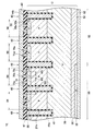
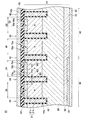
次に、半導体装置10の製造方法を説明する。半導体装置10は、ドリフト領域28と略同じn型不純物濃度を有するn型の半導体基板(シリコン基板)から製造される。まず、エミッタ領域20、ボディ領域21、ドリフト領域28、アノード領域50、トレンチ40、絶縁膜42、トレンチ電極44を形成する。次に、図4に示すように、半導体基板上に層間絶縁膜47を形成する。
20:エミッタ領域
21:ボディ領域
28:ドリフト領域
30:バッファ領域
32:コレクタ領域
40:トレンチ
42:絶縁膜
44:トレンチ電極
47:層間絶縁膜
50:アノード領域
52:カソード領域
60:上部電極
62:下部電極
70:コンタクトホール
74:導電体層
90:IGBT領域
92:ダイオード領域
Claims (7)
- 半導体基板を有する半導体装置であって、
前記半導体基板の上面に形成された平行に伸びる複数のトレンチと、
前記各トレンチの内面を覆うトレンチ絶縁膜と、
前記各トレンチの内部に配置されており、前記トレンチ絶縁膜によって前記半導体基板から絶縁されているトレンチ電極と、
前記複数のトレンチのうちの隣り合うトレンチに挟まれた第1範囲内の前記半導体基板に形成されており、前記半導体基板の前記上面に露出しており、前記トレンチ絶縁膜に接している第1導電型の第1半導体層と、
前記第1範囲内の前記半導体基板に形成されており、一部が前記半導体基板の前記上面に露出しており、前記第1半導体層の下側で前記トレンチ絶縁膜に接している第2導電型の第2半導体層と、
前記半導体基板に形成されており、前記第2半導体層の下側に配置されており、前記第2半導体層によって前記第1半導体層から分離されており、前記第2半導体層の下側で前記トレンチ絶縁膜に接している第1導電型の第3半導体層と、
前記半導体基板の前記上面及び前記トレンチ電極上に配置されており、前記第1範囲内に配置された複数のコンタクトホールを有する層間絶縁膜と、
前記各コンタクトホール内に配置されており、前記第1半導体層と前記第2半導体層の少なくとも一方に接続されている第1導電体層と、
前記第1導電体層上及び前記層間絶縁膜上に配置されており、前記各第1導電体層に接続されている表面電極、
を有し、
前記各コンタクトホールが、前記各トレンチと平行な方向に沿って長く伸びており、
前記第1範囲に隣接する2つのトレンチのうちの一方から他方に向かう方向に、前記複数のコンタクトホールが間隔を開けて配列されている、
半導体装置。 - 前記第1範囲とは異なる前記複数のトレンチのうちの隣り合うトレンチに挟まれた範囲である第2範囲内の前記半導体基板に形成されており、前記半導体基板の前記上面に露出している第2導電型の第4半導体層と、
第2導電体層、
をさらに有しており、
前記第3半導体層の一部が、前記第4半導体層の下側に配置されており、前記第4半導体層に接しており、
前記層間絶縁膜が、前記第2範囲内に配置されたコンタクトホールを有しており、
前記第2導電体層が、前記第2範囲内の前記コンタクトホール内に配置されており、前記第4半導体層に接続されており、
前記表面電極の一部が、前記第2導電体層上に配置されており、前記第2導電体層に接続されており、
前記複数の第1導電体層の前記半導体基板に対するコンタクト面積を前記第1範囲の面積で除算した値が、前記第2導電体層の前記半導体基板に対するコンタクト面積を前記第2範囲の面積で除算した値よりも大きい、
請求項1の半導体装置。 - 前記第1導電体層のヤング率は、前記表面電極のヤング率よりも高い請求項1または2の半導体装置。
- 前記第1導電体層は、CVD、メッキ、スパッタによって形成可能な材料によって構成されている請求項1〜3のいずれか一項の半導体装置。
- 前記第1導電体層は、W、Al、Cuのいずれかを含む金属によって構成されている請求項1〜4のいずれか一項の半導体装置。
- 前記各トレンチ電極上の前記層間絶縁膜の幅が、前記第1範囲内の複数のコンタクトホールに挟まれた前記層間絶縁膜の幅よりも広い請求項1〜5のいずれか一項の半導体装置。
- 加工用ウエハから半導体装置を製造する方法であって、
前記加工用ウエハが、
平行に伸びる複数のトレンチが上面に形成された半導体基板と、
前記各トレンチの内面を覆うトレンチ絶縁膜と、
前記各トレンチの内部に配置されており、前記トレンチ絶縁膜によって前記半導体基板から絶縁されているトレンチ電極、
を有しており、
前記半導体基板が、
前記複数のトレンチのうちの隣り合うトレンチに挟まれた範囲内に形成されており、前記半導体基板の前記上面に露出しており、前記トレンチ絶縁膜に接している第1導電型の第1半導体層と、
前記範囲内に形成されており、一部が前記半導体基板の前記上面に露出しており、前記第1半導体層の下側で前記トレンチ絶縁膜に接している第2導電型の第2半導体層と、
前記第2半導体層の下側に配置されており、前記第2半導体層によって前記第1半導体層から分離されており、前記第2半導体層の下側で前記トレンチ絶縁膜に接している第1導電型の第3半導体層、
を有しており、
前記方法が、
前記加工用ウエハの上面に、層間絶縁膜を形成する工程と、
前記範囲内の前記層間絶縁膜に、複数のコンタクトホールを形成する工程と、
前記複数のコンタクトホール内及び前記層間絶縁膜上に、導電体層を成長させる工程と、
前記複数のコンタクトホール内に前記導電体層が残存するように前記層間絶縁膜上の前記導電体層をエッチングする工程と、
前記エッチングの後に、前記導電体層上及び前記層間絶縁膜上に、表面電極を形成する工程、
を有し、
前記各コンタクトホールが、前記各トレンチと平行な方向に沿って長く伸びるように形成され、
前記範囲に隣接する2つのトレンチのうちの一方から他方に向かう方向に、前記複数のコンタクトホールが間隔を開けて配列されるように前記各コンタクトホールが形成される、
製造方法。
Priority Applications (3)
| Application Number | Priority Date | Filing Date | Title |
|---|---|---|---|
| JP2014160719A JP6245107B2 (ja) | 2014-08-06 | 2014-08-06 | 半導体装置及び半導体装置の製造方法 |
| US15/325,954 US9966372B2 (en) | 2014-08-06 | 2015-06-08 | Semiconductor device and method of manufacturing semiconductor device having parallel contact holes between adjacent trenches |
| PCT/JP2015/066523 WO2016021299A1 (ja) | 2014-08-06 | 2015-06-08 | 半導体装置及び半導体装置の製造方法 |
Applications Claiming Priority (1)
| Application Number | Priority Date | Filing Date | Title |
|---|---|---|---|
| JP2014160719A JP6245107B2 (ja) | 2014-08-06 | 2014-08-06 | 半導体装置及び半導体装置の製造方法 |
Publications (3)
| Publication Number | Publication Date |
|---|---|
| JP2016039215A JP2016039215A (ja) | 2016-03-22 |
| JP2016039215A5 JP2016039215A5 (ja) | 2016-12-08 |
| JP6245107B2 true JP6245107B2 (ja) | 2017-12-13 |
Family
ID=55263577
Family Applications (1)
| Application Number | Title | Priority Date | Filing Date |
|---|---|---|---|
| JP2014160719A Active JP6245107B2 (ja) | 2014-08-06 | 2014-08-06 | 半導体装置及び半導体装置の製造方法 |
Country Status (3)
| Country | Link |
|---|---|
| US (1) | US9966372B2 (ja) |
| JP (1) | JP6245107B2 (ja) |
| WO (1) | WO2016021299A1 (ja) |
Families Citing this family (4)
| Publication number | Priority date | Publication date | Assignee | Title |
|---|---|---|---|---|
| JP6673499B2 (ja) * | 2016-11-17 | 2020-03-25 | 富士電機株式会社 | 半導体装置 |
| US10510832B2 (en) | 2017-07-14 | 2019-12-17 | Fuji Electric Co., Ltd. | Semiconductor device |
| JP7143575B2 (ja) | 2017-07-18 | 2022-09-29 | 富士電機株式会社 | 半導体装置 |
| JP6958210B2 (ja) * | 2017-10-11 | 2021-11-02 | 株式会社デンソー | 半導体装置 |
Family Cites Families (7)
| Publication number | Priority date | Publication date | Assignee | Title |
|---|---|---|---|---|
| JP4797265B2 (ja) * | 2001-03-21 | 2011-10-19 | 富士電機株式会社 | 半導体装置および半導体装置の製造方法 |
| JP2011044494A (ja) | 2009-08-19 | 2011-03-03 | Panasonic Corp | 半導体装置およびその製造方法 |
| JP5566272B2 (ja) * | 2010-11-26 | 2014-08-06 | 三菱電機株式会社 | 半導体装置 |
| DE112012005869B4 (de) | 2012-02-14 | 2021-09-23 | Denso Corporation | IGBT und IGBT-Herstellungsverfahren |
| JP2014013850A (ja) * | 2012-07-05 | 2014-01-23 | Sumitomo Electric Ind Ltd | 炭化珪素基板および半導体装置の製造方法、ならびに炭化珪素基板および半導体装置 |
| JP6112600B2 (ja) | 2012-12-10 | 2017-04-12 | ローム株式会社 | 半導体装置および半導体装置の製造方法 |
| JP5924420B2 (ja) * | 2012-12-20 | 2016-05-25 | トヨタ自動車株式会社 | 半導体装置 |
-
2014
- 2014-08-06 JP JP2014160719A patent/JP6245107B2/ja active Active
-
2015
- 2015-06-08 US US15/325,954 patent/US9966372B2/en active Active
- 2015-06-08 WO PCT/JP2015/066523 patent/WO2016021299A1/ja active Application Filing
Also Published As
| Publication number | Publication date |
|---|---|
| JP2016039215A (ja) | 2016-03-22 |
| US9966372B2 (en) | 2018-05-08 |
| US20170162563A1 (en) | 2017-06-08 |
| WO2016021299A1 (ja) | 2016-02-11 |
Similar Documents
| Publication | Publication Date | Title |
|---|---|---|
| JP6135636B2 (ja) | 半導体装置 | |
| JP6274154B2 (ja) | 逆導通igbt | |
| JP6197773B2 (ja) | 半導体装置 | |
| KR101231077B1 (ko) | 반도체장치 | |
| JP2015118966A (ja) | 半導体装置 | |
| JP5867484B2 (ja) | 半導体装置の製造方法 | |
| JP6245107B2 (ja) | 半導体装置及び半導体装置の製造方法 | |
| JP5487956B2 (ja) | 半導体装置 | |
| JP2010135646A (ja) | 半導体装置 | |
| KR20190098452A (ko) | 신뢰성이 고려된 배면 구조를 가진 전력 반도체 | |
| JP2010232335A (ja) | 絶縁ゲートバイポーラトランジスタ | |
| US9607961B2 (en) | Semiconductor device | |
| JP2013161918A (ja) | 半導体装置 | |
| US11916112B2 (en) | SiC semiconductor device | |
| JP2019106430A (ja) | 半導体装置 | |
| JP6217708B2 (ja) | 半導体装置とその製造方法 | |
| JP2010258385A (ja) | 炭化珪素半導体装置およびその製造方法 | |
| US11658238B2 (en) | Semiconductor device | |
| JP2009182217A (ja) | 半導体装置およびその製造方法 | |
| JP7274974B2 (ja) | 半導体装置 | |
| JP6620889B2 (ja) | 半導体装置 | |
| JP7158317B2 (ja) | 半導体装置 | |
| JP6852541B2 (ja) | 半導体装置 | |
| JP2017054928A (ja) | 半導体装置 | |
| JP5358141B2 (ja) | 半導体装置 |
Legal Events
| Date | Code | Title | Description |
|---|---|---|---|
| A621 | Written request for application examination |
Free format text: JAPANESE INTERMEDIATE CODE: A621 Effective date: 20160728 |
|
| A521 | Request for written amendment filed |
Free format text: JAPANESE INTERMEDIATE CODE: A523 Effective date: 20161021 |
|
| A131 | Notification of reasons for refusal |
Free format text: JAPANESE INTERMEDIATE CODE: A131 Effective date: 20170502 |
|
| A521 | Request for written amendment filed |
Free format text: JAPANESE INTERMEDIATE CODE: A523 Effective date: 20170524 |
|
| TRDD | Decision of grant or rejection written | ||
| A01 | Written decision to grant a patent or to grant a registration (utility model) |
Free format text: JAPANESE INTERMEDIATE CODE: A01 Effective date: 20171017 |
|
| A61 | First payment of annual fees (during grant procedure) |
Free format text: JAPANESE INTERMEDIATE CODE: A61 Effective date: 20171030 |
|
| R151 | Written notification of patent or utility model registration |
Ref document number: 6245107 Country of ref document: JP Free format text: JAPANESE INTERMEDIATE CODE: R151 |
|
| S111 | Request for change of ownership or part of ownership |
Free format text: JAPANESE INTERMEDIATE CODE: R313113 |
|
| R350 | Written notification of registration of transfer |
Free format text: JAPANESE INTERMEDIATE CODE: R350 |
|
| R250 | Receipt of annual fees |
Free format text: JAPANESE INTERMEDIATE CODE: R250 |
|
| R250 | Receipt of annual fees |
Free format text: JAPANESE INTERMEDIATE CODE: R250 |
|
| R250 | Receipt of annual fees |
Free format text: JAPANESE INTERMEDIATE CODE: R250 |
|
| R250 | Receipt of annual fees |
Free format text: JAPANESE INTERMEDIATE CODE: R250 |