JP4188202B2 - Game machine - Google Patents
Game machine Download PDFInfo
- Publication number
- JP4188202B2 JP4188202B2 JP2003365356A JP2003365356A JP4188202B2 JP 4188202 B2 JP4188202 B2 JP 4188202B2 JP 2003365356 A JP2003365356 A JP 2003365356A JP 2003365356 A JP2003365356 A JP 2003365356A JP 4188202 B2 JP4188202 B2 JP 4188202B2
- Authority
- JP
- Japan
- Prior art keywords
- display
- variation display
- identification information
- variation
- special symbol
- Prior art date
- Legal status (The legal status is an assumption and is not a legal conclusion. Google has not performed a legal analysis and makes no representation as to the accuracy of the status listed.)
- Expired - Fee Related
Links
Images


Landscapes
- Display Devices Of Pinball Game Machines (AREA)
- Pinball Game Machines (AREA)
Description
本発明は、遊技媒体を遊技領域に発射することにより遊技者が遊技を行い、あらかじめ定められている第1の始動条件または第2の始動条件が成立した後、変動表示の開始条件の成立にもとづいて各々が識別可能な第1の識別情報または第2の識別情報の変動表示を開始し、当該第1の識別情報または第2の識別情報の変動表示の表示結果が特定表示結果となったときに遊技者にとって有利な特定遊技状態に制御可能となるパチンコ遊技機等の遊技機に関する。 In the present invention, after a player plays a game by firing a game medium into the game area, and the predetermined first start condition or the second start condition is satisfied, the start condition of the variable display is satisfied. Based on this, the variable display of the first identification information or the second identification information that can be identified is started, and the display result of the variable display of the first identification information or the second identification information becomes the specific display result. The present invention relates to a gaming machine such as a pachinko gaming machine that can be controlled to a specific gaming state that is sometimes advantageous to the player.
遊技機として、遊技球などの遊技媒体を発射装置によって遊技領域に発射し、遊技領域に設けられている入賞口などの入賞領域に遊技媒体が入賞すると、所定個の賞球が遊技者に払い出されるものがある。さらに、識別情報を可変表示可能な可変表示手段が設けられ、入賞領域のうちの始動領域である始動入賞口に遊技媒体が入賞すると、可変表示手段において識別情報の変動表示が実行され、当該識別情報の可変表示の表示結果が特定の表示結果となった場合に遊技者にとって有利な特定遊技状態に制御可能となるように構成されたものがある。 As a gaming machine, a game medium such as a game ball is launched into a game area by a launching device, and when a game medium wins a prize area such as a prize opening provided in the game area, a predetermined number of prize balls are paid out to the player. There is something to be done. Furthermore, a variable display means capable of variably displaying the identification information is provided, and when the game medium wins a winning winning opening that is a starting area of the winning areas, the variable display means executes a variable display of the identification information, and the identification information is displayed. There is one configured to be able to control to a specific gaming state advantageous to the player when the display result of the variable display of information becomes a specific display result.
特定遊技状態とは、所定の遊技価値が付与された遊技者にとって有利な状態を意味する。具体的には、特定遊技状態は、例えば可変入賞球装置の状態が打球が入賞しやすい遊技者にとって有利な状態(大当り遊技状態)、遊技者にとって有利な状態となるための権利が発生した状態、景品遊技媒体払出の条件が成立しやすくなる状態などの、所定の遊技価値が付与された状態である。なお、賞球や得点などの遊技の結果として付与される価値を遊技価値と呼ぶこともある。 The specific game state means a state advantageous for a player who is given a predetermined game value. Specifically, the specific gaming state is, for example, a state in which the state of the variable winning ball apparatus is advantageous for a player who is easy to win a ball (a big hit gaming state), or a state in which a right to be advantageous for a player has occurred. A state in which a predetermined game value is given, such as a state where conditions for paying out premium game media are easily established. A value given as a result of a game such as a prize ball or a score may be referred to as a game value.
パチンコ遊技機では、特別図柄(識別情報)を表示する可変表示手段の表示結果があらかじめ定められた特定の表示態様の組合せとなることを、通常、「大当り」という。大当りが発生すると、例えば、大入賞口が所定回数開放して打球が入賞しやすい大当り遊技状態に移行する。そして、各開放期間において、所定個(例えば10個)の大入賞口への入賞があると大入賞口は閉成する。そして、大入賞口の開放回数は、所定回数(例えば15ラウンド)に固定されている。なお、各開放について開放時間(例えば29.5秒)が決められ、入賞数が所定個に達しなくても開放時間が経過すると大入賞口は閉成する。また、大入賞口が閉成した時点で所定の条件(例えば、大入賞口内に設けられているVゾーンへの入賞)が成立していない場合には、大当り遊技状態は終了する。 In a pachinko gaming machine, the fact that the display result of the variable display means for displaying a special symbol (identification information) is a combination of specific display modes determined in advance is usually called “big hit”. When the big hit occurs, for example, the big winning opening is opened a predetermined number of times, and the game shifts to a big hit gaming state where the hit ball is easy to win. And in each open period, if there is a prize for a predetermined number (for example, 10) of the big prize opening, the big prize opening is closed. And the number of times the special winning opening is opened is fixed to a predetermined number (for example, 15 rounds). An opening time (for example, 29.5 seconds) is determined for each opening, and even if the number of winnings does not reach a predetermined number, the big winning opening is closed when the opening time elapses. Further, when a predetermined condition (for example, winning in the V zone provided in the big prize opening) is not established at the time when the big prize opening is closed, the big hit gaming state is ended.
また、可変表示手段において最終停止図柄(例えば左右中図柄のうち中図柄)となる図柄以外の図柄が、所定時間継続して、特定の表示結果と一致している状態で停止、揺動、拡大縮小もしくは変形している状態、または、複数の図柄が同一図柄で同期して変動したり、表示図柄の位置が入れ替わっていたりして、最終結果が表示される前で大当り発生の可能性が継続している状態(以下、これらの状態をリーチ状態という。)において行われる演出をリーチ演出という。なお、最終停止図柄となる図柄以外の図柄が、特定の表示結果と一致していることを「リーチ」という。また、リーチ状態やその様子をリーチ態様という。さらに、リーチ演出を含む可変表示をリーチ可変表示という。リーチ状態において、変動パターンを通常状態における変動パターンとは異なるパターンにすることによって、遊技の興趣が高められている。そして、可変表示手段に可変表示される図柄の表示結果がリーチ状態となる条件を満たさない場合には「はずれ」となり、可変表示状態は終了する。遊技者は、大当りをいかにして発生させるかを楽しみつつ遊技を行う。 In addition, the symbols other than the symbol that becomes the final stop symbol (for example, the middle symbol of the left and right middle symbols) on the variable display means continue for a predetermined time and stop, swing, or expand in a state that matches the specific display result. The possibility of big hits continues before the final result is displayed due to a reduced or deformed state, or multiple symbols changing synchronously with the same symbol, or the position of the display symbol changing. An effect performed in a state in which the player is in a state (hereinafter, these states are referred to as reach states) is referred to as reach effect. It should be noted that “reach” means that a symbol other than the symbol that is the final stop symbol matches the specific display result. Further, the reach state and its state are referred to as a reach mode. Furthermore, variable display including reach production is called reach variable display. In the reach state, the interest of the game is enhanced by making the variation pattern different from the variation pattern in the normal state. And when the display result of the symbol variably displayed on the variable display means does not satisfy the condition for reaching the reach state, it becomes “displaced”, and the variable display state ends. A player plays a game while enjoying how to generate a big hit.
このような遊技機として、特別図柄を表示する表示器が複数設けられ、複数箇所で特別図柄の変動表示が行われるものがある(例えば、特許文献1参照)。 As such a gaming machine, there is one in which a plurality of indicators for displaying special symbols are provided, and special symbols are variably displayed at a plurality of locations (see, for example, Patent Document 1).
特許文献1に記載された遊技機では、遊技領域内の離れた場所にある別個の表示領域で特別図柄の変動表示を別々に行うというだけであり、遊技の興趣を向上させるまでには至っていないと考えられる。
In the gaming machine described in
また、特別図柄を複数箇所で変動表示させるため、遊技者にとっては、いずれの表示器で変動表示が実行されるのか分かりづらいという問題があった。 In addition, since special symbols are variably displayed at a plurality of locations, there is a problem that it is difficult for the player to understand which display is used to display the variability display.
そこで、本発明は、識別情報の変動表示を行う表示領域が複数設けられた遊技機において、ゲーム性を高めることができるとともに、遊技の内容を遊技者に容易に認識させることができ、遊技の興趣を向上させることができる遊技機を提供することを目的とする。 Therefore, the present invention can improve the game performance in a gaming machine provided with a plurality of display areas for performing variable display of identification information, and can make the player easily recognize the contents of the game. An object is to provide a gaming machine capable of improving interest.
本発明による遊技機は、遊技媒体を遊技領域に発射することにより遊技者が遊技を行い、あらかじめ定められている第1の始動条件(例えば始動入賞口14Aに遊技球が入賞したことにより有効始動入賞が発生したこと)または第2の始動条件(例えば始動入賞口14Bに遊技球が入賞したことにより有効始動入賞が発生したこと)が成立した後、変動表示の開始条件(例えば、前回の特別図柄の可変表示および大当り遊技状態が終了し、かつ、総始動入賞記憶数が0でないこと)の成立にもとづいて各々が識別可能な第1の識別情報(例えば第1特別図柄)または第2の識別情報(例えば第2特別図柄)の変動表示を開始し、当該第1の識別情報または第2の識別情報の変動表示の表示結果が特定表示結果(例えばあらかじめ定められた大当り図柄)となったときに遊技者にとって有利な特定遊技状態(例えば大当り遊技状態)に制御可能となる遊技機であって、第1の始動条件が成立したことにもとづいて第1の識別情報の変動時間を特定可能な変動表示態様を決定し、第2の始動条件が成立したことにもとづいて第2の識別情報の変動時間を特定可能な変動表示態様を決定する特別変動表示態様決定手段(例えばCPU56を含む遊技制御手段におけるステップS54a〜S62,ステップS54b〜S62を実行する部分)と、特別変動表示態様決定手段が決定した変動表示態様を記憶する変動表示態様記憶手段(例えば遊技制御手段におけるステップS62dを実行する部分)と、特別変動表示態様決定手段により決定された第1の識別情報の変動表示態様にもとづいて、第1の変動表示部(例えば特別図柄表示器33)にて第1の識別情報の変動表示を行わせる第1の変動表示制御手段と、特別変動表示態様決定手段により決定された第2の識別情報の変動表示態様にもとづいて、第2の変動表示部(例えば特別図柄表示器39)にて第2の識別情報の変動表示を行わせる第2の変動表示制御手段と、第1の始動条件は成立したが未だ開始条件が成立していない変動表示の開始をあらかじめ定められている第1の上限数(例えば「4」)まで保留記憶する第1の保留記憶手段(例えば第1特別図柄判定用バッファ)と、第2の始動条件は成立したが未だ開始条件が成立していない変動表示の開始をあらかじめ定められている第2の上限数(例えば「4」)まで保留記憶する第2の保留記憶手段(例えば第2特別図柄判定用バッファ)と、第1の識別情報および第2の識別情報の変動表示態様にもとづいて、第1の識別情報および第2の識別情報の変動表示態様に対応する第3の識別情報の変動時間を特定可能な飾り変動表示態様を決定する飾り変動表示態様決定手段(例えば表示制御用CPU101を含む表示制御手段におけるステップS804a,S804bを実行する部分)と、飾り変動表示態様決定手段が決定した飾り変動表示態様を記憶する飾り変動表示態様記憶手段(例えば表示制御手段におけるステップS804fを実行する部分)と、飾り変動表示態様決定手段により決定された第3の識別情報の飾り変動表示態様にもとづいて、第1の識別情報の変動表示と第2の識別情報の変動表示の開始と停止に対応して第3の変動表示部(例えば可変表示装置9)にて1箇所での第3の識別情報の変動表示の開始と停止を行わせる第3の変動表示制御手段と、第1の保留記憶手段が記憶している保留数(例えば第1始動入賞記憶数)と第2の保留記憶手段が記憶している保留数(例えば第2始動入賞記憶数)との総数である総保留数(例えば総始動入賞記憶数)が特定可能(例えば遊技者が特定することができる)な総保留数特定表示を行う保留記憶数表示手段(例えば可変表示装置9における始動記憶数表示エリア18)と、を備え、第1の変動表示制御手段および第2の変動表示制御手段は、第1の識別情報と第2の識別情報のいずれか一方の変動表示が行われているときに、変動表示が行われていない他方の識別情報の開始条件が成立した場合、変動表示が行われている一方の識別情報の変動表示の停止を待たずに他方の識別情報の変動表示が開始されることにより第1の識別情報と第2の識別情報とが同時に変動表示可能であり、特別変動表示態様決定手段は、変動表示態様記憶手段が記憶している既に決定された変動表示態様にもとづいて、後に変動表示が開始された他方の識別情報の変動表示が先に変動表示が開始された一方の識別情報の変動表示よりも後に停止する他方の識別情報の変動表示態様を決定し、飾り変動表示態様決定手段は、飾り変動表示態様記憶手段が記憶している既に決定された飾り変動表示態様にもとづいて、第1の識別情報と第2の識別情報とが同時に変動表示している場合において、同時に変動表示が行われたのち第1の識別情報と第2の識別情報のいずれか一方の変動表示が停止したときから、未だ変動表示が行われている他方の識別情報の変動表示が停止するときまでの残り変動時間に対応させて飾り変動表示態様を決定することを特徴とする。
In the gaming machine according to the present invention, a player plays a game by launching a game medium into the game area, and the game machine is effectively started when a predetermined first start condition (for example, a game ball wins a start winning opening 14A). After a winning condition has been established) or a second starting condition (for example, an effective starting prize has been generated by winning a game ball in the starting prize opening 14B), a variable display start condition (for example, the special The first identification information (for example, the first special symbol) or the second identification information that can be identified based on the establishment of the variable display of symbols and the big hit gaming state is completed and the total starting winning memory number is not 0) The variable information display of the identification information (for example, the second special symbol) is started, and the display result of the variable display of the first identification information or the second identification information is the specific display result (for example, Ri a controllable become gaming machine to an advantageous specific gaming state (e.g. jackpot gaming state) for the player when a symbol), the first identification information based on the first starting condition is established Special variation display mode determining means for determining a variation display mode that can identify the variation time of the second identification information and determining a variation display mode that can identify the variation time of the second identification information based on the fact that the second start condition is satisfied (For example, a portion for executing steps S54a to S62 and steps S54b to S62 in the game control means including the CPU 56) and a variation display mode storage unit (for example, a game control unit) that stores the variation display mode determined by the special variation display mode determination unit. step S62d and the portions for performing), based on the variable display mode of the first identification information determined by the particular variable display mode determining means in A first variable display control means for causing the variable display of the first identification information in the first variable display unit (e.g., the special symbol display device 33), a second identification which are determined by a special change display mode decision unit Based on the information variation display mode , second variation display control means for causing the second variation display section (for example, the special symbol display 39) to perform variation display of the second identification information, and a first start condition The first hold storage means (for example, the first special symbol determination, for example) that holds the start of the variable display for which the start condition is not yet satisfied up to a predetermined first upper limit number (for example, “4”). Buffer), and the second start-up of the variable display in which the second start condition is satisfied but the start condition is not yet satisfied is suspended and stored up to a predetermined second upper limit number (for example, “4”). Holding storage means (for example, second special The third identification information corresponding to the variation display mode of the first identification information and the second identification information based on the variation display mode of the symbol determination buffer) and the first identification information and the second identification information. Decoration variation display mode determination means (for example, a portion for executing steps S804a and S804b in the display control means including the display control CPU 101) and decoration variation display mode determination means for determining a decoration variation display mode that can specify the variation time. The decoration variation display mode storage unit (for example, the portion of the display control unit that executes step S804f) that stores the decoration variation display mode and the decoration variation display mode of the third identification information determined by the decoration variation display mode determination unit. based, the third variable display unit in response to starting and stopping variable display of the variable display and the second identification information of the first identification information (for example Variable display device 9) by the third and the third variable display control means for causing start and stop the variable display of the identification information, the number of holding the first holding memory means has stored in one place (e.g. The total number of holds (for example, the total number of start winning prizes) that is the total of the number of holds (for example, the number of second start prizes stored) stored in the second holding storage means (for example, the total number of start winning prizes) can be specified ( For example, a reserved memory number display means (for example, a start memory
第1の始動条件または第2の始動条件が成立したことにもとづいて、第3の識別情報の変動表示の変動表示態様を決定する飾り変動表示態様決定手段(例えば表示制御用CPU101を含む表示制御手段におけるステップS804a,S804bを実行する部分)を備え、第3の識別情報の変動表示は、第1の始動条件と第2の始動条件との成立順番に従って順次行われ、飾り変動表示態様決定手段は、第1の始動条件と第2の始動条件とのうち成立順番が最先の始動条件の開始条件が成立する前に、当該成立順番が最先の始動条件にもとづく変動表示の後に行われる第1または第2の識別情報の変動表示の変動表示態様を判定し(例えばステップS804h)、当該判定結果に応じて、成立順番が最先の始動条件にもとづく第1または第2の識別情報の変動表示に応じて実行する第3の識別情報の変動表示の変動表示態様を決定する(例えばステップS804i,S804j)ように構成されていてもよい。
Decoration variation display mode determination means (for example, display control including the
遊技領域に設けられた第1の始動入賞領域を遊技媒体が通過したことを検出する第1の始動検出手段(例えば始動口スイッチ14a)と、第1の始動検出手段とは異なり、遊技領域に設けられた第2の始動入賞領域を遊技媒体が通過したことを検出する第2の始動検出手段(例えば始動口スイッチ14b)と、第1の始動入賞領域の遊技媒体の通過を第1の始動検出手段が検出したことにもとづいて第1の始動条件が成立したと判定する第1始動条件判定手段(例えば遊技制御手段におけるステップS311,S111を実行する部分)と、第2の始動入賞領域の遊技媒体の通過を第2の始動検出手段が検出したことにもとづいて第2の始動条件が成立したと判定する第2始動条件判定手段(例えば遊技制御手段におけるステップS313,S121を実行する部分)と、を備えていてもよい。
Unlike the first start detection means and the first start detection means for detecting that the game medium has passed through the first start winning area provided in the game area and the first start detection means, the game area A second start detection means (for example, a
第1の識別情報の変動表示の表示結果を特定表示結果とするか否かの第1決定確率と、第2の識別情報の変動表示の表示結果を特定表示結果とするか否かの第2決定確率とを記憶する特定確率記憶手段(例えばROM54における第1の大当り判定用テーブルと第2の大当り判定用テーブルとが格納された記憶領域)を備え、特定確率記憶手段は、第1決定確率とは異なる確率の第2決定確率を記憶するように構成されていてもよい。 A first determination probability as to whether or not the display result of the variation display of the first identification information is the specific display result, and a second as to whether or not the display result of the variation display of the second identification information is the specific display result Specific probability storage means for storing a determination probability (for example, a storage area in which the first jackpot determination table and the second jackpot determination table in the ROM 54 are stored), and the specific probability storage means includes a first determination probability. It may be configured to store the second determination probabilities having different probabilities.
特定遊技状態は、あらかじめ複数種類(例えば、大入賞口の開放回数が異なるもの、時短の有無など)設けられており、第1の識別情報の変動表示の表示結果が特定表示結果となったときと、第2の識別情報の変動表示の表示結果が特定表示結果となったときとで、異なる種類の特定遊技状態に制御する特定遊技状態制御手段(例えばCPU56におけるステップS59a,S59bでの決定結果に応じて制御を行う部分)を備えていてもよい。 There are multiple types of specific game states (for example, different winning opening times, presence / absence of time), and the display result of the variable display of the first identification information is the specific display result. And when the display result of the variation display of the second identification information becomes the specific display result, the specific game state control means for controlling to a different type of specific game state (for example, determination results in steps S59a and S59b in the CPU 56) May be provided).
請求項1記載の発明によれば、第1、第2、および第3の変動表示部を用いて識別情報の変動表示制御を行う構成としたので、ゲーム性を高めることができ、遊技の興趣を向上させることができる。また、第3の変動表示制御手段が、第1の識別情報の変動表示と第2の識別情報の変動表示の開始と停止に対応して第3の変動表示部にて1箇所での第3の識別情報を変動表示の開始と停止を行わせ、保留記憶数表示手段が、第1の保留記憶手段が記憶している保留数と第2の保留記憶手段が記憶している保留数との総数である総保留数が特定可能な総保留数特定表示を行う構成としたので、遊技の内容を遊技者に容易に認識させることができる。 According to the first aspect of the present invention, since the variation display control of the identification information is performed using the first, second, and third variation display units, the game performance can be enhanced, and the game is interesting. Can be improved. The third variable display control means, a third in one place at the third variable display unit in response to starting and stopping variable display of the variable display and the second identification information of the first identification information The identification display information is started and stopped in a variable display , and the hold memory number display means calculates the hold number stored in the first hold storage means and the hold number stored in the second hold storage means. Since the total number-of-holds specific display which can specify the total number of holds, which is the total number, is performed , the contents of the game can be easily recognized by the player.
請求項2記載の発明では、第1の識別情報の変動表示の始動条件と第2の識別情報の変動表示の始動条件とが、それぞれ異なる始動検出手段の検出によって成立するようにすることができ、ゲーム性を向上させることができる。 In the second aspect of the present invention, the starting conditions of the variable display of the first identification information and the start condition of the variable display of the second identification information, is to Rukoto to stand by the detection of different start detecting means Can improve the game performance.
請求項3記載の発明では、第1の識別情報の変動表示が実行されたときと、第2の識別情報の変動表示が実行されたときとで、特定遊技状態となる確率を異ならせることができ、ゲーム性を向上させることができる。
In the invention according to
以下、本発明の実施の形態を図面を参照して説明する。
まず、遊技機の一例である第1種パチンコ遊技機の全体の構成について説明する。図1はパチンコ遊技機を正面からみた正面図である。
Hereinafter, embodiments of the present invention will be described with reference to the drawings.
First, the overall configuration of a first type pachinko gaming machine that is an example of a gaming machine will be described. FIG. 1 is a front view of a pachinko gaming machine as viewed from the front.
パチンコ遊技機1は、縦長の方形状に形成された外枠(図示せず)と、外枠の内側に開閉可能に取り付けられた遊技枠とで構成される。また、パチンコ遊技機1は、遊技枠に開閉可能に設けられている額縁状に形成されたガラス扉枠2を有する。遊技枠は、外枠に対して開閉自在に設置される前面枠(図示せず)と、機構部品等が取り付けられる機構板と、それらに取り付けられる種々の部品(後述する遊技盤を除く。)とを含む構造体である。
The
図1に示すように、パチンコ遊技機1は、額縁状に形成されたガラス扉枠2を有する。ガラス扉枠2の下部表面には打球供給皿(上皿)3がある。打球供給皿3の下部には、打球供給皿3に収容しきれない遊技球を貯留する余剰球受皿4と打球を発射する打球操作ハンドル(操作ノブ)5が設けられている。ガラス扉枠2の背面には、遊技盤6が着脱可能に取り付けられている。なお、遊技盤6は、それを構成する板状体と、その板状体に取り付けられた種々の部品とを含む構造体である。また、遊技盤6の前面には遊技領域7が形成されている。
As shown in FIG. 1, the
遊技領域7の中央付近には、それぞれが識別情報としての飾り図柄を可変表示する複数の可変表示部を含む可変表示装置(特別可変表示部)9が設けられている。可変表示装置9には、例えば「左」、「中」、「右」の3つの可変表示部(図柄表示エリア)がある。
Near the center of the
可変表示装置9の下方の左右には、始動入賞口14Aを含む可変入賞球装置15Aと、始動入賞口14Bを含む可変入賞球装置15Bとが設けられている。始動入賞口14Aに入った入賞球は、遊技盤6の背面に導かれ、始動口スイッチ14aによって検出される。また、可変入賞球装置15Aは、開閉動作を行う左右の開閉片を備えている。この開閉片は、ソレノイド16Aによって開状態とされる。始動入賞口14Bに入った入賞球は、遊技盤6の背面に導かれ、始動口スイッチ14bによって検出される。また、可変入賞球装置15Bは、開閉動作を行う左右の開閉片を備えている。この開閉片は、ソレノイド16Bによって開状態とされる。なお、スイッチやソレノイドについては、図1には図示されていない。
A variable winning
また、可変表示装置9の表示領域には、始動入賞口14A,14Bに入った有効入賞球数すなわち始動入賞記憶数を表示する特別図柄始動記憶数表示エリア(始動記憶数表示エリア)18が設けれている。本例では、始動記憶数表示エリア18には、第1始動入賞記憶数と第2始動入賞記憶数との総数である総始動入賞記憶数が表示される。第1始動入賞記憶数は、始動入賞口14Aへの入賞(第1始動入賞)にもとづく始動入賞記憶数であり、第2始動入賞記憶数は、始動入賞口14Bへの入賞(第2始動入賞)にもとづく始動入賞記憶数である。
In the display area of the variable display device 9, there is provided a special symbol start memory number display area (start memory number display area) 18 for displaying the number of effective winning balls entered into the
この例では、有効始動入賞(始動入賞記憶数があらかじめ定められている上限数未満のときに発生した始動入賞)がある毎に、始動記憶数表示エリア18に表示されている始動入賞記憶数を示す表示エリアを1増やす。そして、可変表示装置9の可変表示が開始される毎に、始動記憶数表示エリア18に表示されている始動入賞記憶数を示す表示エリアを1減らす。
In this example, every time there is a valid start prize (a start prize generated when the start prize memory number is less than the predetermined upper limit number), the start prize memory number displayed in the start memory
なお、始動入賞記憶の上限数は、第1始動入賞にもとづく始動入賞記憶と、第2始動入賞記憶数は、第2始動入賞にもとづく始動入賞記憶とでそれぞれ定められている。よって、有効始動入賞となるか否かは、第1始動入賞と第2始動入賞とで別個に判断される。また、総始動入賞記憶の上限数は、第1始動入賞にもとづく始動入賞記の上限数と、憶第1始動入賞にもとづく始動入賞記憶の上限数とを加算した値となる。 The upper limit number of start prize memories is determined by the start prize memory based on the first start prize, and the second start prize memory is determined by the start prize memory based on the second start prize. Therefore, whether or not it becomes an effective start prize is determined separately for the first start prize and the second start prize. Further, the upper limit number of the total start winning memory is a value obtained by adding the upper limit number of the start winning record based on the first start winning and the upper limit number of the starting winning memory based on the first start winning memory.
なお、始動入賞記憶数は、可変表示装置9以外の他の表示器を用いて表示するようにしてもよい。また、始動入賞記憶数は、数値により表すようにしてもよいし、例えば始動入賞記憶数に応じた数のランプを点灯させるなどのような他の方法で表すようにしてもよい。 The start winning memory number may be displayed using a display other than the variable display device 9. Further, the start winning memory number may be expressed by a numerical value, or may be expressed by other methods such as lighting a number of lamps corresponding to the starting winning memory number.
可変入賞球装置15Aの左側には、それぞれが識別情報としての特別図柄を可変表示(変動表示)する複数の可変表示部を含む特別図柄表示器33が設けられている。特別図柄表示器33には、例えば「左」、「右」の3つの可変表示部(特別図柄表示エリア)がある。本例では、特別図柄表示器33にて変動表示される特別図柄を、第1特別図柄と呼ぶことにする。
On the left side of the variable winning
また、可変入賞球装置15Bの右側には、それぞれが識別情報としての特別図柄を可変表示する複数の可変表示部を含む特別図柄表示器39が設けられている。特別図柄表示器39には、例えば「左」、「右」の3つの可変表示部(特別図柄表示エリア)がある。本例では、特別図柄表示器39にて変動表示される特別図柄を、第2特別図柄と呼ぶことにする。
Also, a
遊技領域7の下方には、特定遊技状態(大当り状態)においてソレノイド21によって開状態とされる開閉板20が設けられている。開閉板20は大入賞口を開閉する手段である。開閉板20から遊技盤6の背面に導かれた入賞球のうち一方(V入賞領域)に入った入賞球はV入賞スイッチ22で検出され、開閉板20からの入賞球はカウントスイッチ23で検出される。遊技盤6の背面には、大入賞口内の経路を切り換えるためのソレノイド21Aも設けられている。
Below the
ゲート32A,32Bに遊技球が入賞しゲートスイッチ32a,32bで検出されると、普通図柄始動入賞記憶が上限に達していなければ、所定の乱数値が抽出される。そして、普通図柄表示器10において表示状態が変化する可変表示を開始できる状態であれば、普通図柄表示器10の表示の可変表示が開始される。普通図柄表示器10において表示状態が変化する可変表示を開始できる状態でなければ、普通図柄始動入賞記憶の値が1増やされる。普通図柄表示器10の近傍には、普通図柄始動入賞記憶数を表示する4つのLEDによる表示部を有する普通図柄始動記憶表示器41が設けられている。ゲート32A,32Bへの入賞がある毎に、普通図柄始動記憶表示器41は点灯するLEDを1増やす。そして、普通図柄表示器10の可変表示が開始される毎に、点灯するLEDを1減らす。なお、特別図柄と普通図柄とを一つの可変表示装置で可変表示するように構成することもできる。その場合には、特別可変表示部と普通可変表示部とは1つの可変表示装置で実現される。
When a game ball wins the gates 32A and 32B and is detected by the gate switches 32a and 32b, a predetermined random number value is extracted if the normal symbol start winning memory does not reach the upper limit. And if it is a state which can start the variable display in which a display state changes in the
この実施の形態では、左右のランプ(点灯時に図柄が視認可能になる)が交互に点灯することによって普通図柄の可変表示が行われ、可変表示は所定時間(例えば29.2秒)継続する。そして、可変表示の終了時に左側のランプが点灯すれば当りとなる。当りとするか否かは、ゲート32A,32Bに遊技球が入賞したときに抽出された乱数の値が所定の当り判定値と一致したか否かによって決定される。普通図柄表示器10における可変表示の表示結果が当りである場合に、可変入賞球装置15A,15Bが所定回数、所定時間だけ開状態になって遊技球が入賞しやすい状態になる。すなわち、可変入賞球装置15A,15Bの状態は、普通図柄の停止図柄が当り図柄である場合に、遊技者にとって不利な状態から有利な状態に変化する。
In this embodiment, the left and right lamps (the symbols can be visually recognized at the time of lighting) are alternately turned on, whereby the normal symbols are variably displayed, and the variable display continues for a predetermined time (for example, 29.2 seconds). If the left lamp is turned on at the end of the variable display, it is a win. Whether or not to win is determined by whether or not the value of the random number extracted when the game ball wins the gates 32A and 32B matches a predetermined hit determination value. When the display result of the variable display on the
さらに、後述する特別遊技状態としての確変状態では、普通図柄表示器10における停止図柄が当り図柄になる確率が高められる(例えば、当りとなる確率が1/10から9/10に高められる)とともに、可変入賞球装置15の開放時間と開放回数とのうちの一方または双方が高められ(例えば、開放時間が0.5秒から3秒に増加されたり、開放回数が1回から2回に増加される)、遊技者にとってさらに有利になる。また、確変状態等の所定の状態では、普通図柄表示器10における可変表示期間(変動時間)が短縮される(例えば、29.2秒から1秒に短縮される)ことによって、遊技者にとってさらに有利になるようにしてもよい。
Further, in the probability variation state as the special gaming state described later, the probability that the stop symbol in the
遊技盤6には、複数の入賞口29,30が設けられ、遊技球の入賞口29,30への入賞は、それぞれ入賞口スイッチ29a,30aによって検出される。遊技領域7の左右周辺には、遊技中に点滅表示される飾りランプ25が設けられ、下部には、入賞しなかった打球を吸収するアウト口26がある。また、遊技領域7の外側の左右上部には、効果音や音声を発する2つのスピーカ27が設けられている。遊技領域7の外周には、天枠ランプ28a、左枠ランプ28bおよび右枠ランプ28cが設けられている。
The
そして、この例では、左枠ランプ28bの近傍に、賞球残数があるときに点灯する賞球ランプ51が設けられ、右枠ランプ28cの近傍に、補給球が切れたときに点灯する球切れランプ52が設けられている。
In this example, a
打球発射装置から発射された遊技球は、打球レールを通って遊技領域7に入り、その後、遊技領域7を下りてくる。打球が始動入賞口14A,14Bに入り始動口スイッチ14a,14bで検出されると、図柄の可変表示を開始できる状態であれば、特別図柄表示器33,39において特別図柄が可変表示を始めるとともに、可変表示装置9において飾り図柄が可変表示を始める。図柄の可変表示を開始できる状態でなければ、第1始動入賞記憶数または第2始動入賞記憶数を1増やすとともに、総始動入賞記憶数を1増やす。
The game balls launched from the hit ball launching device enter the
可変表示装置9における飾り図柄の可変表示は、一定時間が経過したときに停止する。停止時の飾り図柄の組み合わせが大当り図柄(特定表示態様)であると、大当り遊技状態に移行する。すなわち、開閉板20が、一定時間経過するまで、または、所定個数(例えば10個)の打球が入賞するまで開放する。そして、開閉板20の開放中に打球がV入賞領域に入賞しV入賞スイッチ22で検出されると、継続権が発生し開閉板20の開放が再度行われる。継続権の発生は、所定回数(例えば15ラウンド)許容される。
The variable display of the decorative symbols on the variable display device 9 stops when a certain time has elapsed. If the combination of the decorative symbols at the time of the stop is a jackpot symbol (specific display mode), the game shifts to a jackpot gaming state. That is, the opening /
停止時の可変表示装置9における飾り図柄の組み合わせが確率変動を伴う大当り図柄(確変図柄)の組み合わせである場合には、次に大当りとなる確率が高くなる。すなわち、確変状態という遊技者にとってさらに有利な状態(特別遊技状態)となる。 When the combination of decorative symbols on the variable display device 9 at the time of stoppage is a combination of jackpot symbols (probability variation symbols) with a probability variation, the probability of the next jackpot increases. That is, it becomes a more advantageous state (special game state) for the player, which is a probable change state.
図2は、遊技機の裏面に設置されている遊技制御基板(主基板)31における回路構成の一例を示すブロック図である。なお、図2には、払出制御基板37、ランプ制御基板35、音制御基板70、発射制御基板91および表示制御基板80も示されている。主基板31には、プログラムに従ってパチンコ遊技機1を制御する基本回路53と、ゲートスイッチ32a,32b、始動口スイッチ14a,14b、V入賞スイッチ22、カウントスイッチ23、入賞口スイッチ29a,30a、満タンスイッチ48およびクリアスイッチ921からの信号を基本回路53に与えるスイッチ回路58と、可変入賞球装置15Aを開閉するソレノイド16A、可変入賞球装置15Bを開閉するソレノイド16B、開閉板20を開閉するソレノイド21および大入賞口内の経路を切り換えるためのソレノイド21Aを基本回路53からの指令に従って駆動するソレノイド回路59とが搭載されている。
FIG. 2 is a block diagram showing an example of a circuit configuration of the game control board (main board) 31 installed on the back surface of the gaming machine. 2 also shows a payout control board 37, a
なお、ゲートスイッチ32a,32b、始動口スイッチ14a,14b、V入賞スイッチ22、カウントスイッチ23、入賞口スイッチ29a,30a等のスイッチは、センサと称されているものでもよい。すなわち、遊技球を検出できる遊技球検出手段(遊技媒体検出手段の一例)であれば、その名称を問わない。
Note that the switches such as the gate switches 32a and 32b, the
また、主基板31には、基本回路53から与えられるデータに従って、大当りの発生を示す大当り情報、特別図柄の可変表示開始に利用された始動入賞球の個数を示す有効始動情報、確率変動が生じたことを示す確変情報等の情報出力信号をホールコンピュータ等の外部機器に対して出力する情報出力回路64が搭載されている。
In addition, according to the data given from the basic circuit 53, the main board 31 generates jackpot information indicating the occurrence of the jackpot, effective starting information indicating the number of starting winning balls used for the variable symbol display start, and probability fluctuations. An
基本回路53は、ゲーム制御用のプログラム等を記憶するROM54、ワークメモリとして使用される記憶手段(変動データを記憶する手段)としてのRAM55、プログラムに従って制御動作を行うCPU56およびI/Oポート部57を含む。この実施の形態では、ROM54,RAM55はCPU56に内蔵されている。すなわち、CPU56は、1チップマイクロコンピュータである。なお、1チップマイクロコンピュータは、少なくともRAM55が内蔵されていればよく、ROM54およびI/Oポート部57は外付けであっても内蔵されていてもよい。
The basic circuit 53 includes a ROM 54 for storing a game control program and the like, a
また、RAM(CPU内蔵RAMであってもよい)55は、一部または全部が、遊技機が備える電源基板(図示せず)において作成されるバックアップ電源によってバックアップされているバックアップRAMである。すなわち、遊技機に対する電力供給が停止しても、所定期間は、RAM55の一部または全部の内容は保存される。
The RAM 55 (which may be a CPU built-in RAM) is a backup RAM that is partially or entirely backed up by a backup power source created on a power supply board (not shown) provided in the gaming machine. That is, even if the power supply to the gaming machine is stopped, a part or all of the contents of the
遊技球を打撃して発射する打球発射装置は発射制御基板91上の回路によって制御される駆動モータ94で駆動される。そして、駆動モータ94の駆動力は、操作ノブ5の操作量に従って調整される。すなわち、発射制御基板91上の回路によって、操作ノブ5の操作量に応じた速度で打球が発射されるように制御される。
A ball hitting device for hitting and launching a game ball is driven by a
なお、この実施の形態では、ランプ制御基板35に搭載されているランプ制御用CPU(ランプ制御手段)が、遊技盤に設けられている普通図柄始動記憶表示器41およびサイドランプ25等の表示制御を行うとともに、枠側に設けられている天枠ランプ28a、左枠ランプ28b、右枠ランプ28c、賞球ランプ51および球切れランプ52の表示制御を行う。なお、各ランプはLEDその他の種類の発光体でもよい。すなわち、ランプやLEDは発光体の一例であり、以下、ランプ・LEDと総称することがある。
In this embodiment, the lamp control CPU (lamp control means) mounted on the
ランプ制御手段は、ランプ・LEDを駆動するための駆動信号を作成して各発光体に出力する。なお、遊技機に演出手段としての可動部材が設置されている場合には、ランプ制御手段は、可動部材を駆動するためのモータやソレノイド等の演出用駆動手段を駆動するための駆動信号を作成して出力する処理を行う。 The lamp control means creates a drive signal for driving the lamp / LED and outputs it to each light emitter. When a movable member is provided as a production means in the gaming machine, the lamp control means creates a drive signal for driving the production drive means such as a motor or a solenoid for driving the movable member. Process to output.
また、可変表示装置9、普通図柄表示器10、特別図柄表示器33および特別図柄表示器39の表示制御は、表示制御基板80に搭載されている表示制御手段によって行われる。また、音制御基板70に搭載されている音制御用CPU(音制御手段)701がスピーカ27の制御を行う。そして、景品としての遊技球の払い出しを行う球払出装置97は、払出制御基板37に搭載されている払出制御用CPU(払出制御手段)によって制御される。ランプ制御手段および音制御手段は一つの基板に搭載されていてもよい。また、表示制御手段、ランプ制御手段および音制御手段が一つの基板に搭載されていてもよい。さらに、表示制御基板80、ランプ制御基板35、音制御基板70によって制御される電気部品の一部又は全部を、主基板31が制御する構成としてもよい。
The display control of the variable display device 9, the
図3は、表示制御基板80、ランプ制御基板35および音声制御基板70の回路構成例を示すブロック図である。表示制御基板80、ランプ制御基板35および音声制御基板70では、主基板31からの制御コマンドに応じて、各種の処理を実行する。
FIG. 3 is a block diagram illustrating a circuit configuration example of the
表示制御基板80は、表示制御用のプログラム等を記憶するROM102、ワークメモリとして使用される記憶手段としてのRAM103、主基板31からの表示制御コマンドに従って表示制御を行う表示制御用マイクロコンピュータとしての表示制御用CPU101を含む。
The
表示制御基板80において、表示制御用CPU101は、ROM102に格納されたプログラムに従って動作し、主基板31からのストローブ信号(表示制御INT信号)に応じて、表示制御コマンドを受信する。また、表示制御用CPU101は、表示制御コマンドにもとづいて、図示しないVDP(ビデオディスプレイプロセッサ)に、LCDを用いた可変表示装置9の表示制御を行わせる。VDPは、GCL(グラフィックコントローラLSI)と呼ばれることもある。
In the
この実施の形態では、総始動入賞記憶数を示す表示制御コマンドが主基板31から表示制御基板80に出力される。表示制御用CPU101は、総始動入賞記憶数を示す表示制御コマンドにもとづいて、可変表示装置9の表示制御を行い、始動記憶数表示エリア18に総始動入賞記憶数を表示させる。
In this embodiment, a display control command indicating the total number of start winning memories is output from the main board 31 to the
ランプ制御基板35は、発光体制御用のプログラム等を記憶するROM352、ワークメモリとして使用される記憶手段としてのRAM353、主基板31からのランプ制御コマンドに従って発光体制御を行う発光体制御用マイクロコンピュータとしてのランプ制御用CPU351を含む。
The
この実施の形態では、サイドランプ25の点灯/消灯を示すランプ制御コマンドが主基板31からランプ制御基板35に出力される。また、普通図柄始動記憶表示器41の点灯個数を示すランプ制御コマンドも主基板31からランプ制御基板35に出力される。
In this embodiment, a lamp control command indicating lighting / extinguishing of the
ランプ制御に関するランプ制御コマンドは、CPU56におけるI/Oポート部57から出力される。I/Oポート部57は、8ビットのデータと、1ビットのINT信号とを出力する。ランプ制御基板35において、主基板31からのランプ制御コマンドは、ランプ制御基板35におけるI/Oポート部の入力ポートを介してランプ制御用CPU351に入力する。
A lamp control command related to the lamp control is output from the I /
ランプ制御基板35において、ランプ制御用CPU351は、各制御コマンドに応じて定義されているサイドランプ25の点灯/消灯パターンに従って、サイドランプ25に対して点灯/消灯信号を出力する。なお、点灯/消灯パターンは、ROM353(ランプ制御用CPU351の内蔵ROMまたは外付けROM)に記憶されている。
On the
音声制御基板70は、音声制御用のプログラムや音声データ等を記憶する音声データROM702、主基板31からの音制御コマンドに従って音声出力制御を行う音制御用マイクロコンピュータとしての音声制御用CPU701を含む。
The
この実施の形態では、遊技進行に応じて、遊技領域7の外側に設けられているスピーカ27の音声出力を指示するための音制御コマンドが、主基板31から音声制御基板70に出力される。
In this embodiment, a sound control command for instructing sound output from the
音制御コマンドは、CPU56におけるI/Oポート部57から出力される。I/Oポート部57は、8ビットのデータと、1ビットのINT信号とを出力する。音声制御基板70において、主基板31からの音制御コマンドは、音声制御基板70におけるI/Oポート部の入力ポートを介して音制御用CPU701に入力する。音制御用CPU701は、受信した音制御コマンドに応じたデータを音声データROM702から読み出す。
The sound control command is output from the I /
そして、音制御用CPU701は、音声や効果音を発生し増幅回路703に出力する。増幅回路703は、音声制御用CPU701の出力レベルを、ボリューム704にて設定されている音量(例えば、遊技機に設けられているボリューム切替スイッチの操作状態に応じた音量)に応じたレベルに増幅した音声信号をスピーカ27に出力する。
The
音声データROM702に格納されている音制御コマンドに応じたデータは、所定期間(例えば特別図柄の変動期間)における効果音または音声の出力態様を時系列的に示すデータの集まりである。音制御用CPU701は、音制御コマンドを受信すると、音声データROM702内の対応するデータに従って音出力制御を行う。対応するデータに従った音出力制御は、次の音制御コマンドを受信するまで継続される。そして、音制御用CPU701は、次の音制御コマンドを受信すると、新た入力した音制御コマンドに対応した音声データROM702内のデータに従って音出力制御を行う。
The data corresponding to the sound control command stored in the
次に遊技機の動作について説明する。先ず、主基板31における遊技制御手段(CPU56およびROM,RAM等の周辺回路)が実行するメイン処理について説明する。遊技機に対して電源が投入され、リセット端子の入力レベルがハイレベルになると、CPU56は、メイン処理を開始する。メイン処理において、CPU56は、まず、必要な初期設定を行う。
Next, the operation of the gaming machine will be described. First, main processing executed by game control means (
次いで、CPU56は、遊技機への電力供給が停止したときにバックアップRAM領域のデータ保護処理(例えばパリティデータの付加等の電力供給停止時処理)が行われたか否か確認する。そのような保護処理が行われていないことを確認したら、CPU56は初期化処理を実行する。バックアップRAM領域にバックアップデータがあるか否かは、例えば、電力供給停止時処理においてバックアップRAM領域に設定されるバックアップフラグの状態によって確認される。
Next, the
バックアップありを確認したら、CPU56は、バックアップRAM領域のデータチェック(この例ではパリティチェック)を行う。チェック結果が正常でなければ、内部状態を電力供給停止時の状態に戻すことができないので、電力供給の停止からの復旧時でない電源投入時に実行される初期化処理を実行する。
After confirming that there is a backup, the
チェック結果が正常であれば、CPU56は、遊技制御手段の内部状態と表示制御手段等の電気部品制御手段の制御状態を電力供給停止時の状態に戻すための遊技状態復旧処理を行う。そして、バックアップRAM領域に保存されていたPC(プログラムカウンタ)の退避値がPCに設定され、そのアドレスに復帰する。
If the check result is normal, the
初期化処理では、CPU56は、まず、RAMクリア処理を行う。また、所定の作業領域(例えば、普通図柄判定用乱数カウンタ、普通図柄判定用バッファ、特別図柄左右図柄バッファ、特別図柄プロセスフラグ、払出コマンド格納ポインタ、賞球中フラグ、球切れフラグ、払出停止フラグなど制御状態に応じて選択的に処理を行うためのフラグ)に初期値を設定する作業領域設定処理を行う。さらに、サブ基板(この実施の形態では払出制御基板37、表示制御基板80、ランプ制御基板35、音声制御基板70)を初期化するための初期化コマンドを各サブ基板に送信する処理を実行する。初期化コマンドとして、可変表示装置9に表示される初期図柄を示すコマンドや賞球ランプ51および球切れランプ52の消灯を指示するコマンド等がある。
In the initialization process, the
そして、2ms毎に定期的にタイマ割込がかかるようにCPU56に設けられているCTCのレジスタの設定が行われる。すなわち、初期値として2msに相当する値が所定のレジスタ(時間定数レジスタ)に設定される。
Then, a CTC register set in the
初期化処理の実行が完了すると、メイン処理で、表示用乱数更新処理および初期値用乱数更新処理が繰り返し実行される。表示用乱数更新処理および初期値用乱数更新処理が実行されるときには割込禁止状態とされ、表示用乱数更新処理および初期値用乱数更新処理の実行が終了すると割込許可状態とされる。表示用乱数とは、特別図柄表示器33,39に表示される図柄を決定するための乱数であり、表示用乱数更新処理とは、表示用乱数を発生するためのカウンタのカウント値を更新する処理である。また、初期値用乱数更新処理とは、初期値用乱数を発生するためのカウンタのカウント値を更新する処理である。初期値用乱数とは、大当りとするか否かを決定するための乱数を発生するためのカウンタ(大当り判定用乱数発生カウンタ)等の、カウント値の初期値を決定するための乱数である。後述する遊技制御処理において、大当り判定用乱数発生カウンタのカウント値が1周すると、そのカウンタに初期値が設定される。 When the execution of the initialization process is completed, the display random number update process and the initial value random number update process are repeatedly executed in the main process. When the display random number update process and the initial value random number update process are executed, the interrupt is prohibited. When the display random number update process and the initial value random number update process are finished, the interrupt is permitted. The display random number is a random number for determining the symbol displayed on the special symbol displays 33 and 39, and the display random number update processing is to update the count value of the counter for generating the display random number. It is processing. The initial value random number update process is a process for updating the count value of the counter for generating the initial value random number. The initial value random number is a random number for determining the initial value of the count value, such as a counter for generating a random number for determining whether or not to make a big hit (a big hit determination random number generation counter). In a game control process described later, when the count value of the jackpot determination random number generation counter makes one round, an initial value is set in the counter.
次に、2ms毎に発生するタイマ割込を契機として実行されるタイマ割込処理(遊技制御処理)について説明する。
タイマ割込が発生すると、CPU56は、遊技制御処理を実行する。遊技制御処理において、CPU56は、まず、電源断信号が出力されたか否か(オン状態になったか否か)を検出する電源断検出処理を実行する。電源断信号は、例えば電源基板に搭載されている電圧低下監視回路が、遊技機に供給される電源の電圧の低下を検出した場合に出力する。そして、電源断検出処理において、CPU56は、電源断信号が出力されたことを検出したら、必要なデータをバックアップRAM領域に保存するための電力供給停止時処理を実行する。次いで、スイッチ回路58を介して、ゲートスイッチ32a,32b、始動口スイッチ14a,14b、カウントスイッチ23および入賞口スイッチ24a等のスイッチの検出信号を入力し、それらの状態判定を行う(スイッチ処理)。
Next, a timer interrupt process (game control process) executed with a timer interrupt generated every 2 ms as a trigger will be described.
When the timer interrupt occurs, the
次に、遊技制御に用いられる大当り判定用の乱数等の各判定用乱数を生成するための各カウンタのカウント値を更新する処理を行う(判定用乱数更新処理)。CPU56は、さらに、初期値用乱数を生成するためのカウンタのカウント値を更新する処理および表示用乱数を生成するためのカウンタのカウント値を更新する処理を行う(表示用乱数更新処理)。
Next, a process of updating the count value of each counter for generating each determination random number such as a big hit determination random number used for game control is performed (determination random number update process). The
ここで、本例の遊技機で用いられる各乱数について説明する。各乱数は、以下のように使用される。
(1)ランダム1:大当りを発生させるか否か決定する(大当り判定用)
(2)ランダム2−1〜2−3(ランダム2):特別図柄の左中右のはずれ図柄決定用(特別図柄左中右)
(3)ランダム3:大当りを発生させる特別図柄の組合せを決定する(大当り図柄決定用)
(4)ランダム4:特別図柄の変動パターンを決定する(変動パターン決定用)
(5)ランダム5:大当りを発生させない場合にリーチとするか否かを決定する(リーチ判定用)
(6)ランダム6:普通図柄にもとづく当りを発生させるか否か決定する(普通図柄当り判定用)
(7)ランダム7:ランダム1の初期値を決定する(ランダム1初期値決定用)
(8)ランダム8:ランダム6の初期値を決定する(ランダム6初期値決定用)
Here, each random number used in the gaming machine of this example will be described. Each random number is used as follows.
(1) Random 1: Decide whether or not to generate a big hit (for big hit judgment)
(2) Random 2-1 to 2-3 (Random 2): For determining the left middle right of the special symbol (special symbol left middle right)
(3) Random 3: Determines the combination of special symbols that generate a big hit (for determining big hit symbols)
(4) Random 4: Determine the variation pattern of the special symbol (for variation pattern determination)
(5) Random 5: Decide whether or not to reach when no big hit is generated (for reach determination)
(6) Random 6: Determines whether or not to generate a hit based on a normal symbol (for normal symbol hit determination)
(7) Random 7: Determine initial value of random 1 (for determining random 1 initial value)
(8) Random 8: Determine initial value of random 6 (for determining random 6 initial value)
遊技制御処理における判定用乱数更新処理では、CPU56は、(1)の大当り判定用乱数、(3)の大当り図柄決定用乱数、および(6)の普通図柄当り判定用乱数を生成するためのカウンタのカウントアップ(1加算)を行う。すなわち、それらが判定用乱数であり、それら以外の乱数が表示用乱数または初期値用乱数である。なお、遊技効果を高めるために、上記(1)〜(8)の乱数以外の普通図柄に関する乱数等も用いられている。
In the determination random number update process in the game control process, the
さらに、CPU56は、特別図柄プロセス処理を行う。特別図柄プロセス制御では、遊技状態に応じてパチンコ遊技機1を所定の順序で制御するための特別図柄プロセスフラグに従って該当する処理が選び出されて実行される。そして、特別図柄プロセスフラグの値は、遊技状態に応じて各処理中に更新される。また、普通図柄プロセス処理を行う。普通図柄プロセス処理では、普通図柄表示器10の表示状態を所定の順序で制御するための普通図柄プロセスフラグに従って該当する処理が選び出されて実行される。そして、普通図柄プロセスフラグの値は、遊技状態に応じて各処理中に更新される。
Further, the
次いで、CPU56は、特別図柄に関する表示制御コマンドをRAM55の所定の領域に設定して表示制御コマンドを送出する処理を行う(特別図柄コマンド制御処理)。また、普通図柄に関する表示制御コマンドをRAM55の所定の領域に設定して表示制御コマンドを送出する処理を行う(普通図柄コマンド制御処理)。
Next, the
また、CPU56は、入賞口スイッチ29a,30aの検出信号にもとづく賞球個数の設定などを行う賞球処理を実行する。
Further, the
そして、CPU56は、総始動入賞記憶数の増減をチェックする記憶処理を実行する。記憶処理では、CPU56は、総始動入賞記憶カウンタのカウント値が前回総始動入賞記憶カウンタのカウント値と同じであるか否か確認し、同じでなければ、すなわち総始動入賞記憶数に変化が生じていれば、総始動入賞記憶数に応じた総始動入賞記憶指定のコマンド送信テーブルのアドレスをポインタにセットし、サブルーチンであるコマンドセット処理を実行する。そして、総始動入賞記憶カウンタのカウント値を、前回総始動入賞記憶カウンタに設定しておく。このようにして、記憶処理において、総始動入賞記憶数が変化したときには、表示制御基板80に搭載されている表示制御手段に対して、総始動入賞記憶数指定の表示制御コマンドが送信される。
And CPU56 performs the memory | storage process which checks the increase / decrease in the total start prize memory | storage number. In the storing process, the
また、遊技機の制御状態を遊技機外部で確認できるようにするための情報出力信号を送信する情報出力信号送信処理を実行する。さらに、所定の条件が成立したときにソレノイド回路59に駆動指令を行う。可変入賞球装置15A,15Bや開閉板20を開状態または閉状態としたり、大入賞口内の遊技球通路を切り替えたりするために、ソレノイド回路59は、駆動指令に応じてソレノイド16A,16B,21,21Aを駆動する。その後、割込許可状態に設定する。
Also, an information output signal transmission process for transmitting an information output signal for enabling the control state of the gaming machine to be confirmed outside the gaming machine is executed. Furthermore, a drive command is issued to the
この実施の形態では、以上のような遊技制御処理が実行され、この遊技制御処理は2ms毎に起動されることになる。なお、この実施の形態では、タイマ割込処理で遊技制御処理が実行されているが、タイマ割込処理では例えば割込が発生したことを示すフラグのセットのみがなされ、遊技制御処理はメイン処理において実行されるようにしてもよい。 In this embodiment, the game control process as described above is executed, and this game control process is started every 2 ms. In this embodiment, the game control process is executed by the timer interrupt process. However, in the timer interrupt process, for example, only a flag indicating that an interrupt has occurred is set, and the game control process is performed by the main process. May be executed.
図4は、CPU56が実行する特別図柄プロセス処理のプログラムの一例を示すフローチャートである。図4に示す処理は、上述した遊技制御処理における特別図柄プロセス処理の具体的な処理である。CPU56は、特別図柄プロセス処理を行う際に、変動短縮タイマ減算処理(ステップS310)を行い、遊技盤6に設けられている始動入賞口14Aに遊技球が入賞したことを検出するための始動口スイッチ14aがオンしていたら、すなわち遊技球が始動入賞口14Aに入賞して第1始動入賞が発生していたら(ステップS311)、第1始動口スイッチ通過処理(ステップS312)を行う。
FIG. 4 is a flowchart showing an example of a special symbol process processing program executed by the
また、遊技盤6に設けられている始動入賞口14Bに遊技球が入賞したことを検出するための始動口スイッチ14bがオンしていたら、すなわち遊技球が始動入賞口14Bに入賞して第2始動入賞が発生していたら(ステップS313)、第2始動口スイッチ通過処理(ステップS314)を行う。その後に、内部状態に応じて、ステップS300〜S308のうちのいずれかの処理を行う。変動短縮タイマは、特別図柄の変動時間が短縮される場合に、変動時間を設定するためのタイマである。なお、始動口スイッチ14a,14bがオンしたか否かは、上述したスイッチ処理での始動口スイッチ14a,14bの状態判定結果に応じて判定される。
Further, if the
特別図柄通常処理(ステップS300):特別図柄の可変表示を開始できる状態になるのを待つ。特別図柄の可変表示が開始できる状態になると、総始動入賞記憶数を確認する。総始動入賞記憶数が0でなければ、特別図柄の可変表示の結果を特定表示結果とするか否か、すなわち大当りとするか否か決定する。そして、内部状態(特別図柄プロセスフラグ)をステップS301に移行するように更新する。 Special symbol normal processing (step S300): Waits until the variable symbol variable display can be started. When the special symbol variable display can be started, the total start winning memory number is confirmed. If the total start winning memory number is not 0, it is determined whether or not the result of variable display of the special symbol is the specific display result, that is, whether or not it is a big hit. Then, the internal state (special symbol process flag) is updated so as to shift to step S301.
特別図柄停止図柄設定処理(ステップS301):特別図柄の可変表示後の停止図柄を決定する。そして、内部状態(特別図柄プロセスフラグ)をステップS302に移行するように更新する。 Special symbol stop symbol setting process (step S301): A stop symbol after variable display of the special symbol is determined. Then, the internal state (special symbol process flag) is updated so as to shift to step S302.
変動パターン設定処理(ステップS302):特別図柄の可変表示の変動パターン(可変表示態様)を、ランダム4の値に応じて決定する。また、変動時間タイマをスタートさせる。このとき、表示制御基板80に対して、最終停止図柄と変動態様(変動パターン)を指令する情報とが送信される。そして、内部状態(特別図柄プロセスフラグ)をステップS303に移行するように更新する。
Fluctuation pattern setting process (step S302): A variation pattern (variable display mode) of variable display of special symbols is determined according to a random 4 value. Also, a variable time timer is started. At this time, the final stop symbol and information for instructing the variation mode (variation pattern) are transmitted to the
特別図柄変動処理(ステップS303):所定時間(ステップS302の変動時間タイマで示された時間)が経過すると、内部状態(特別図柄プロセスフラグ)をステップS304に移行するように更新する。 Special symbol variation process (step S303): When a predetermined time (the time indicated by the variation time timer in step S302) elapses, the internal state (special symbol process flag) is updated to shift to step S304.
特別図柄停止処理(ステップS304):可変表示装置9において表示される全図柄が停止されるように制御する。具体的には、特別図柄停止を示す表示制御コマンドが送信される状態に設定する。そして、停止図柄が大当り図柄である場合には、内部状態(特別図柄プロセスフラグ)をステップS305に移行するように更新する。そうでない場合には、内部状態(特別図柄プロセスフラグ)をステップS300に移行するように更新する。 Special symbol stop process (step S304): Control is performed so that all symbols displayed on the variable display device 9 are stopped. Specifically, it is set to a state in which a display control command indicating special symbol stop is transmitted. If the stop symbol is a big hit symbol, the internal state (special symbol process flag) is updated to shift to step S305. Otherwise, the internal state (special symbol process flag) is updated to shift to step S300.
大入賞口開放前処理(ステップS305):大入賞口を開放する制御を開始する。具体的には、カウンタやフラグを初期化するとともに、ソレノイド21を駆動して大入賞口を開放する。また、プロセスタイマによって大入賞口開放中処理の実行時間を設定し、大当り中フラグをセットする。そして、内部状態(特別図柄プロセスフラグ)をステップS306に移行するように更新する。
Preliminary winning opening opening process (step S305): Control for opening the large winning opening is started. Specifically, the counter and the flag are initialized, and the
大入賞口開放中処理(ステップS306):大入賞口ラウンド表示の表示制御コマンドを表示制御基板80に送出する制御や大入賞口の閉成条件の成立を確認する処理等を行う。最後の大入賞口の閉成条件が成立したら、内部状態(特別図柄プロセスフラグ)をステップS307に移行するように更新する。
Processing for opening a special prize opening (step S306): Control for sending a display control command for round display of a special prize opening to the
特定領域有効時間処理(ステップS307):V入賞スイッチ22の通過の有無を監視して、大当り遊技状態継続条件の成立を確認する処理を行う。大当り遊技状態継続の条件が成立し、かつ、まだ残りラウンドがある場合には、内部状態(特別図柄プロセスフラグ)をステップS305に移行するように更新する。また、所定の有効時間内に大当り遊技状態継続条件が成立しなかった場合、または、全てのラウンドを終えた場合には、内部状態(特別図柄プロセスフラグ)をステップS308に移行するように更新する。
Specific area valid time process (step S307): The presence / absence of passing through the
大当り終了処理(ステップS308):大当り遊技状態が終了したことを遊技者に報知する表示制御を表示制御手段に行わせるための制御を行う。そして、内部状態(特別図柄プロセスフラグ)をステップS300に移行するように更新する。 Big hit end processing (step S308): Control for causing the display control means to perform display control for notifying the player that the big hit gaming state has ended. Then, the internal state (special symbol process flag) is updated so as to shift to step S300.
図5は、始動入賞口14Aに遊技球が入賞したときに実行される第1始動口スイッチ通過処理(ステップS312)を示すフローチャートである。第1始動口スイッチ通過処理において、CPU56は、第1始動入賞記憶数があらかじめ設定されている上限値(例えば「4」)に達しているかどうか確認する(ステップS111)。第1始動入賞記憶数が上限値に達していなければ、第1始動入賞記憶数を1増やすとともに(ステップS112)、総始動入賞記憶数を1増やす(ステップS113)。
FIG. 5 is a flowchart showing a first start port switch passing process (step S312) executed when a game ball wins the
次いで、CPU56は、大当り判定用乱数等の各乱数の値を抽出し、抽出した各乱数の値を、第1保存領域(第1特別図柄判定用バッファ)における第1始動入賞記憶数の値に対応した保存領域に格納する(ステップS114)。なお、乱数を抽出するとは、乱数を生成させるためのカウンタからカウント値を読み出して、読み出したカウント値を乱数値とすることである。ステップS113では、上述したランダム1〜5が抽出される。そして、変動時間を短縮するか否かの判定を行うための変動時間短縮判定時間をセットする(ステップS115)。
Next, the
図6は、始動入賞口14Bに遊技球が入賞したときに実行される第2始動口スイッチ通過処理(ステップS314)を示すフローチャートである。第2始動口スイッチ通過処理において、CPU56は、第2始動入賞記憶数があらかじめ設定されている上限値(例えば「4」)に達しているかどうか確認する(ステップS121)。第2始動入賞記憶数が上限値に達していなければ、第2始動入賞記憶数を1増やすとともに(ステップS122)、総始動入賞記憶数を1増やす(ステップS123)。
FIG. 6 is a flowchart showing a second start port switch passage process (step S314) executed when a game ball wins the start winning port 14B. In the second start port switch passing process, the
次いで、CPU56は、大当り判定用乱数等の各乱数の値を抽出し、抽出した各乱数の値を、第2保存領域(第2特別図柄判定用バッファ)における第2始動入賞記憶数の値に対応した保存領域に格納する(ステップS124)。なお、乱数を抽出するとは、乱数を生成させるためのカウンタからカウント値を読み出して、読み出したカウント値を乱数値とすることである。ステップS124では、上述したランダム1〜5が抽出される。そして、変動時間を短縮するか否かの判定を行うための変動時間短縮判定時間をセットする(ステップS125)。
Next, the
なお、この実施の形態では、特別図柄は、それぞれ、「0」〜「11」の12通りあって、特別図柄表示器33,39において「0」から順に特別図柄の表示が変化することによって特別図柄の変動が実現される。なお、特別図柄の変動中において、表示図柄の表示は非連続的に変化してもよい。また、特別図柄の最終停止図柄(確定図柄)が奇数で停止した場合に大当りとなる。そして、大当りとなる場合において、「3」または「7」で停止したときには、大当り遊技終了後に高確率状態(大当りとなる確率が高められた状態であり、直接的あるいは間接的に大当りとなる確率が高められた状態を意味する「確変状態」と同等の概念である)に移行する。また、高確率状態において、大当りが発生すると、または、所定回の特別図柄の変動が行われると、高確率状態は終了し低確率状態に戻る。
In this embodiment, there are 12 special symbols “0” to “11”, respectively, and the
また、この実施の形態では、左中右の飾り図柄は、それぞれ、「0」〜「9」の10通りあって、可変表示装置9において「0」から順に飾り図柄の表示が変化することによって飾り図柄の変動が実現される。なお、飾り図柄の変動中において、表示図柄の表示は非連続的に変化してもよい。また、特別図柄が大当り図柄となるときは、飾り図柄は、左中右揃った最終停止図柄とされる。また、リーチとすることが決定されているときには、飾り図柄は、左右が揃った最終停止図柄とされる。 Further, in this embodiment, there are 10 decorative patterns on the left, middle and right, respectively, “0” to “9”, and the variable display device 9 changes the display of decorative symbols in order from “0”. Variations in decorative design are realized. Note that the display of the display symbol may change discontinuously during the change of the decorative symbol. Further, when the special symbol becomes a big hit symbol, the decorative symbol is a final stop symbol aligned with the left middle right. Further, when it is determined to reach, the decorative symbol is a final stop symbol in which left and right are aligned.
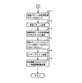
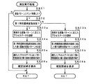
図7,図8は、変動開始時処理を示すフローチャートである。変動開始時処理は、特別図柄プロセス処理における特別図柄通常処理(ステップS300)、特別図柄停止図柄設定処理(ステップS301)、および変動パターン設定処理(ステップS302)をまとめて示す処理である。 7 and 8 are flowcharts showing the fluctuation start process. The variation start process is a process that collectively shows the special symbol normal process (step S300), the special symbol stop symbol setting process (step S301), and the variation pattern setting process (step S302) in the special symbol process.
変動開始時処理において、CPU56は、特別図柄の変動を開始することができる状態(例えば特別図柄プロセスフラグの値がステップS300を示す値となっている場合)には(ステップS51)、総始動入賞記憶数(保留記憶数)の値を確認する(ステップS52)。具体的には、総始動入賞カウンタのカウント値を確認する。なお、特別図柄プロセスフラグの値がステップS300を示す値となっている場合とは、特別図柄表示器33,39において特別図柄の変動がなされておらず、かつ、大当り遊技中でもない場合である。
In the variation start process, the
総始動入賞記憶数が0でなければ、CPU56は、次に実行する特別図柄の変動が、始動入賞口14aへの入賞にもとづく変動であるか、始動入賞口14bへの入賞にもとづく変動であるかを確認する(ステップS53)。ステップS53では、総始動入賞記憶数=1に対応する保存領域に格納されている入賞識別情報に応じて確認する。入賞識別情報は、始動入賞口14aへの入賞にもとづく保留記憶であるか始動入賞口14bへの入賞にもとづく保留記憶であるかを示す情報であり、上述したステップS113(始動入賞口14aへの入賞の場合)やステップS123(始動入賞口14bへの入賞の場合)にて総始動入賞記憶数に対応付けされてRAM55の所定領域に記憶される。
If the total start winning memory number is not 0, the
始動入賞口14aへの入賞にもとづく変動であれば、CPU56は、第1始動入賞記憶数=1に対応する保存領域に格納されている各乱数値を読み出してRAM55の乱数バッファ領域に格納するとともに(ステップS54a)、第1始動入賞記憶数の値を1減らし(第1始動入賞記憶カウンタのカウント値を1減らし)、かつ、各保存領域の内容をシフトする(ステップS55a)。すなわち、第1始動入賞記憶数=n(n=2,3,4)に対応する保存領域(第1始動入賞記憶保存領域)に格納されている各乱数値を、第1始動入賞記憶数=n−1に対応する保存領域に格納する。よって、各第1始動入賞記憶数に対応するそれぞれの保存領域に格納されている各乱数値が抽出された順番は、常に、第1始動入賞記憶数=1,2,3,4の順番と一致するようになっている。すなわち、この例では、CPU56は、可変表示の開始条件が成立する毎に、各第1始動入賞記憶保存領域の内容をシフトする処理を実行するので、始動入賞口14Aへの始動入賞が生じたときに実行された第1始動口スイッチ通過処理の処理結果(具体的にはステップS114の処理結果)が、いずれの第1始動入賞記憶に対応するのかを容易に特定することができる。
If the fluctuation is based on winning at the
また、CPU56は、総始動入賞記憶数の値を1減らし(総始動入賞記憶カウンタのカウント値を1減らし)、かつ、入賞識別情報が格納されている各保存領域の内容をシフトする(ステップS56a)。すなわち、総始動入賞記憶数=n(n=2,3,・・・,8)に対応する保存領域(総始動入賞記憶保存領域)に格納されている各乱数値を、総始動入賞記憶数=n−1に対応する保存領域に格納する。よって、各総始動入賞記憶数に対応するそれぞれの保存領域に格納されている各入賞識別情報の格納順番は、常に、総始動入賞記憶数=1,2,・・・,8の順番と一致するようになっている。すなわち、この例では、CPU56は、可変表示の開始条件が成立する毎に、各総始動入賞記憶保存領域の内容をシフトする処理を実行するので、始動入賞が生じたときに設定された入賞識別情報が、いずれの総始動入賞記憶に対応するのかを容易に特定することができる。
Further, the
次いで、CPU56は、乱数格納バッファから大当り判定用乱数を読み出し(ステップS57a)、大当りとするか否かを判定する大当り判定処理を実行する(ステップS58a)。ステップS58aでは、大当り判定値があらかじめ設定された第1の大当り判定用テーブルが用いられる。大当りとすることに決定した場合には、あらかじめ用意された複数の大当りの種類(特定遊技状態の種類)から1の種類を選択し、いずれの大当りとするかを決定する(ステップS59a)。なお、第1の大当り判定用テーブルは、例えばROM54の所定領域に格納されている。
Next, the
大当りの種類は、例えば、大入賞口の開放回数の上限を異ならせたり、時短の有無、確変の有無、普通図柄の変動時間の短縮の有無、可変入賞球装置15A,15Bの開放回数や開放時間短縮の有無などによって複数設けられる。
The types of jackpots include, for example, different upper limits on the number of times that a big winning opening is opened, whether or not there is a short time, whether or not there is a certain change, whether or not the fluctuation time of a normal symbol is shortened, and how many times the variable winning
なお、大当りとすることに決定しない場合には、乱数格納バッファからリーチ判定用乱数を読み出して、リーチとするか否かを判定するリーチ判定処理を実行する。 If it is not determined to be a big hit, a reach determination random number is read from the random number storage buffer and a reach determination process for determining whether or not to reach is executed.
大当りの有無(はずれの場合にはリーチの有無)を決定すると、CPU56は、第1始動入賞記憶数=1に対応する保存領域に保存されているランダム3の格納値(大当りとする場合)、あるいは、ランダム2の格納値(はずれとする場合)を抽出し、特別図柄の停止図柄を決定する(ステップS60a)。
When the presence / absence of the big hit (the presence / absence of reach in the case of a loss) is determined, the
始動入賞口14bへの入賞にもとづく変動であれば、CPU56は、第2始動入賞記憶数=1に対応する保存領域に格納されている各乱数値を読み出してRAM55の乱数バッファ領域に格納するとともに(ステップS54b)、第2始動入賞記憶数の値を1減らし(第2始動入賞記憶カウンタのカウント値を1減らし)、かつ、各保存領域の内容をシフトする(ステップS55b)。すなわち、第2始動入賞記憶数=n(n=2,3,4)に対応する保存領域(第2始動入賞記憶保存領域)に格納されている各乱数値を、第2始動入賞記憶数=n−1に対応する保存領域に格納する。よって、各第2始動入賞記憶数に対応するそれぞれの保存領域に格納されている各乱数値が抽出された順番は、常に、第2始動入賞記憶数=1,2,3,4の順番と一致するようになっている。すなわち、この例では、CPU56は、可変表示の開始条件が成立する毎に、各第2始動入賞記憶保存領域の内容をシフトする処理を実行するので、始動入賞口14Bへの始動入賞が生じたときに実行された第2始動口スイッチ通過処理の処理結果(具体的にはステップS124の処理結果)が、いずれの第2始動入賞記憶に対応するのかを容易に特定することができる。
If the fluctuation is based on winning at the
また、CPU56は、ステップS56aと同様に、総始動入賞記憶数の値を1減らし(総始動入賞記憶カウンタのカウント値を1減らし)、かつ、入賞識別情報が格納されている各保存領域の内容をシフトする(ステップS56b)。
Similarly to step S56a, the
次いで、CPU56は、乱数格納バッファから大当り判定用乱数を読み出し(ステップS57b)、大当りとするか否かを判定する大当り判定処理を実行する(ステップS58b)。ステップS58bでは、大当り判定値があらかじめ設定された第2の大当り判定用テーブルが用いられる。大当りとすることに決定した場合には、あらかじめ用意された複数の大当りの種類(特定遊技状態の種類)から1の種類を選択し、いずれの大当りとするかを決定する(ステップS59b)。なお、第2の大当り判定用テーブルは、例えばROM54の所定領域に格納されている。
Next, the
ステップS59bでは、上述したステップS59aとは異なる種類の大当りとすることに決定される。すなわち、ステップS59aで選択され得る大当りの種類と、ステップS59bで選択され得る大当りの種類とが異なるように設定されている。例えば、ステップS59aでは、大当り時の大入賞口の開放回数の上限が5回〜8回から選択されるようにし、ステップS59bでは、大当り時の大入賞口の開放回数の上限が12回〜16回から選択されるようにすればよい。このように、第1特別図柄の変動表示によって大当りが発生したときと、第2特別図柄の変動表示によって大当りが発生したときとで、大当りの価値を異ならせるようにすればよい。このように、この実施の形態では、第1の識別情報の変動表示によって特定遊技状態が発生したときと、第2の識別情報の変動表示によって特定遊技状態が発生したときとで、特定遊技状態の種類を異ならせることができ、ゲーム性を向上させることができる。 In step S59b, it is determined that the type of jackpot is different from that in step S59a described above. That is, the type of jackpot that can be selected in step S59a is set to be different from the type of jackpot that can be selected in step S59b. For example, in step S59a, the upper limit of the number of opening of the big winning opening at the time of the big hit is selected from 5 to 8 times, and in step S59b, the upper limit of the number of opening of the big winning opening at the time of the big hit is 12 to 16. It may be selected from times. In this way, the value of the jackpot may be made different between when the big hit is generated by the variation display of the first special symbol and when the big hit is generated by the variation display of the second special symbol. As described above, in this embodiment, the specific gaming state is generated when the specific gaming state is generated by the variation display of the first identification information and when the specific gaming state is generated by the variation display of the second identification information. It is possible to make different types of games and improve the game performance.
なお、大当りとすることに決定しない場合には、乱数格納バッファからリーチ判定用乱数を読み出して、リーチとするか否かを判定するリーチ判定処理を実行する。 If it is not determined to be a big hit, a reach determination random number is read from the random number storage buffer and a reach determination process for determining whether or not to reach is executed.
本例では、第2の大当り判定用テーブルと、第1の大当り判定用テーブルとは、大当りとなる確率が互いに異なるように大当り判定値がそれぞれ設定されている。本例では、第2の大当り判定用テーブルは、第1の大当り判定用テーブルよりも多くの数の大当り判定値が設定されている。すなわち、始動入賞口14Aに遊技球が入賞したときよりも、始動入賞口14Bに遊技球が入賞したときの方が、高確率で大当りとなるように各大当り判定用テーブルが設定されている。
In this example, the jackpot determination values are set so that the second jackpot determination table and the first jackpot determination table have different jackpot probabilities. In this example, the second jackpot determination table is set with a larger number of jackpot determination values than the first jackpot determination table. That is, each jackpot determination table is set so that a big hit is made with high probability when a game ball wins the start winning opening 14B than when a game ball wins the
大当りの有無(はずれの場合にはリーチの有無)を決定すると、CPU56は、第2始動入賞記憶数=1に対応する保存領域に保存されているランダム3の格納値(大当りとする場合)、あるいは、ランダム2の格納値(はずれとする場合)を抽出し、特別図柄の停止図柄を決定する(ステップS60b)。
When the presence / absence of the big hit (the presence / absence of reach in the case of a loss) is determined, the
次いで、CPU56は、変動パターン決定用乱数カウンタから変動パターン決定用乱数を抽出し(ステップS61)、抽出した変動パターン決定用乱数の値に応じて変動パターンを決定する(ステップS62)。具体的には、ステップS62において、あらかじめ用意されている複数種類の変動パターンの中から、あらかじめ定められている変動パターン選択用のテーブルに配されている比較値のうち、抽出した変動パターン決定用乱数の値と一致する比較値が対応付けられている変動パターンとすることに決定される。
Next, the
変動パターンを決定すると、CPU56は、決定した変動パターンの変動時間データを特別図柄プロセスタイマに設定する(ステップS63)。そして、CPU56は、決定した変動パターン指定のコマンド送信テーブルのアドレスをポインタにセットし(ステップS64)、サブルーチンであるコマンドセット処理を実行する(ステップS65)。そして、内部状態(特別図柄プロセスフラグ)をステップS303に移行するように更新する(ステップS66)。
When the variation pattern is determined, the
次に、遊技制御手段から表示制御手段に対する表示制御コマンドの送出方式について説明する。この実施の形態では、表示制御コマンドは、表示制御信号D0〜D7の8本の信号線で主基板31から表示制御基板80に送信される。また、主基板31と表示制御基板80との間には、ストローブ信号(表示制御INT信号)を送信するための表示制御INT信号の信号線が配線されている。すなわち、表示制御コマンドは、8本の信号線と1本のINT信号の信号線によって送信される。なお、表示制御コマンド以外の制御コマンド(払出制御コマンド、ランプ制御コマンド、音制御コマンド)の送出方式も、表示制御コマンドの送出方式と同様である。
Next, a method for sending a display control command from the game control means to the display control means will be described. In this embodiment, the display control command is transmitted from the main board 31 to the
この実施の形態では、表示制御コマンドは2バイト構成であり、1バイト目はMODE(コマンドの分類)を表し、2バイト目はEXT(コマンドの種類)を表す。MODEデータの先頭ビット(ビット7)は必ず「1」とされ、EXTデータの先頭ビット(ビット7)は必ず「0」とされる。なお、そのようなコマンド形態は一例であって他のコマンド形態を用いてもよい。例えば、1バイトや3バイト以上で構成される制御コマンドを用いてもよい。 In this embodiment, the display control command has a 2-byte configuration, the first byte represents MODE (command classification), and the second byte represents EXT (command type). The first bit (bit 7) of the MODE data is always “1”, and the first bit (bit 7) of the EXT data is always “0”. Note that such a command form is an example, and other command forms may be used. For example, a control command composed of 1 byte or 3 bytes or more may be used.
表示制御コマンドの8ビットの表示制御コマンドデータは、表示制御INT信号に同期して出力される。表示制御基板80に搭載されている表示制御手段は、表示制御INT信号が立ち上がったことを検知して、割込処理によって1バイトのデータの取り込み処理を開始する。従って、表示制御手段から見ると、表示制御INT信号は、表示制御コマンドデータの取り込みの契機となる取込信号に相当する。
The 8-bit display control command data of the display control command is output in synchronization with the display control INT signal. The display control means mounted on the
表示制御コマンドは、表示制御手段が認識可能に1回だけ送出される。認識可能とは、この例では、表示制御INT信号のレベルが変化することであり、認識可能に1回だけ送出されるとは、例えば表示制御コマンドデータの1バイト目および2バイト目のそれぞれに応じて表示制御INT信号が1回だけパルス状(矩形波状)に出力されることである。 The display control command is sent only once so that the display control means can recognize it. In this example, “recognizable” means that the level of the display control INT signal changes, and that it is sent only once so as to be recognizable means, for example, that each of the first and second bytes of the display control command data. Accordingly, the display control INT signal is output in a pulse shape (rectangular wave shape) only once.
ここで、表示制御基板80に送出される表示制御コマンドの内容の一例について説明する。特別図柄を可変表示する可変表示装置9における特別図柄の変動パターンを指定する表示制御コマンドは、コマンド8000(H)〜8058(H)とされる。なお、変動パターンを指定するコマンド(変動パターンコマンド)は変動開始指示も兼ねている。
Here, an example of the content of the display control command sent to the
普通図柄の変動パターンに関する表示制御コマンドは、コマンド88XX(H)(X=4ビットの任意の値)とされる。普通図柄の停止図柄を指定する表示制御コマンドは、コマンド89XX(H)とされる。また、普通図柄の可変表示の停止を指示する表示制御コマンドは、コマンド8A00(H)で表される。 The display control command related to the variation pattern of the normal symbol is a command 88XX (H) (X = any value of 4 bits). A display control command for designating a stop symbol of a normal symbol is a command 89XX (H). The display control command for instructing the stop of variable display of normal symbols is represented by command 8A00 (H).
特別図柄の停止図柄を指定する表示制御コマンドは、コマンド91XX(H)で表される。「XX」には図柄番号が設定される。また、特別図柄の可変表示の停止を指示する表示制御コマンドは、コマンドA000(H)とされる。 A display control command for designating a special symbol stop symbol is represented by a command 91XX (H). A symbol number is set in “XX”. The display control command for instructing the stop of variable display of special symbols is command A000 (H).
可変表示装置9の始動入賞記憶数表示領域18に表示される総始動入賞記憶数を示す表示制御コマンドは、コマンドE0XX(H)とされる。例えば、表示制御手段は、始動入賞記憶数表示領域18に「XX(H)」で指定される個数を表示する。すなわち、コマンドE0XX(H)は、保留個数という情報を報知するために設けられている始動入賞記憶数表示領域18の制御を指示するコマンドである。なお、始動入賞記憶数表示領域18に表示する総始動入賞記憶数に関するコマンドが、総始動入賞記憶数の増減を示すように構成されていてもよい。
The display control command indicating the total start winning memory number displayed in the starting winning memory
表示制御基板80の表示制御手段は、主基板31の遊技制御手段から表示制御コマンドを受信すると、その表示制御コマンドに応じて可変表示装置9、普通図柄表示器10、始動入賞記憶数表示領域18の表示状態を変更する。また、ランプ制御基板35のランプ制御手段は、主基板31の遊技制御手段からランプ制御コマンドを受信すると、そのランプ制御コマンドに応じてランプ・LEDの表示状態を変更する。さらに、音声制御基板70の音声制御手段は、主基板31の遊技制御手段から音制御コマンドを受信すると、その音制御コマンドに応じて音声出力制御を実行する。なお、上述した制御コマンド以外の制御コマンドも遊技制御手段から各サブ基板に送信される。例えば、賞球ランプ51や球切れランプ52の表示状態、および普通図柄始動記憶表示器41の点灯個数を示す制御コマンド等や、大当り遊技に関するより詳細な制御コマンドも遊技制御手段から各サブ基板に送信される。
When the display control means of the
可変表示の開始を示す可変表示開始指定コマンドおよび可変表示態様を特定可能な可変表示態様指定コマンドは、変動パターン指定の表示制御コマンドで実現され、識別情報の表示結果を特定可能な識別情報指定コマンドは、左図柄指定、中図柄指定、右図柄指定の表示制御コマンドで実現され、可変表示の終了を示す可変表示終了指定コマンドは、特別図柄停止の表示制御コマンドで実現されている。また、この実施の形態では、変動パターン指定の表示制御コマンドが可変表示の開始を示す可変表示開始指定コマンドおよび可変表示態様を特定可能な可変表示態様指定コマンドとして兼用されているが、可変表示開始指定コマンドと可変表示態様を特定可能な可変表示態様指定コマンドとを別にしてもよい。 The variable display start specifying command for indicating the start of variable display and the variable display mode specifying command for specifying the variable display mode are realized by the display control command for specifying the variation pattern, and the identification information specifying command for specifying the display result of the identification information. Is realized by a display control command for designating left symbol, middle symbol, and right symbol, and a variable display end designating command indicating the end of variable display is realized by a display control command for stopping special symbols. In this embodiment, the display control command for specifying the variation pattern is also used as a variable display start specifying command for indicating the start of variable display and a variable display mode specifying command for specifying the variable display mode. The designation command and the variable display mode designation command that can specify the variable display mode may be separated.
次に、表示制御手段の動作を説明する。まず、表示制御用CPU101が実行するメイン処理について説明する。メイン処理では、RAM領域のクリアや各種初期値の設定、また表示制御の起動間隔を決めるための2msタイマの初期設定等を行うための初期化処理が行われる。その後、表示制御用CPU101は、タイマ割込フラグの監視の確認を行うループ処理に移行する。タイマ割込が発生すると、表示制御用CPU101は、タイマ割込処理においてタイマ割込フラグをセットする。メイン処理において、タイマ割込フラグがセットされていたら、表示制御用CPU101は、そのフラグをクリアし、以下の表示制御処理を実行する。
Next, the operation of the display control means will be described. First, main processing executed by the
この実施の形態では、タイマ割込は2ms毎にかかる。すなわち、表示制御処理は、2ms毎に起動される。また、この実施の形態では、タイマ割込処理ではフラグセットのみがなされ、具体的な表示制御処理はメイン処理において実行されるが、タイマ割込処理で表示制御処理を実行してもよい。 In this embodiment, the timer interrupt takes every 2 ms. That is, the display control process is started every 2 ms. In this embodiment, only the flag is set in the timer interrupt process, and the specific display control process is executed in the main process. However, the display control process may be executed in the timer interrupt process.
表示制御処理において、表示制御用CPU101は、まず、受信した表示制御コマンドを解析する(コマンド解析実行処理)。コマンド解析処理では、表示制御用CPU101は、コマンド受信バッファに格納されている表示制御コマンドの内容を確認し、受信コマンドに対応するフラグのセットなどの処理を行う。例えば、受信コマンドが変動パターンコマンドである場合には、変動パターンコマンド受信フラグをセットするとともに、表示制御コマンド(80XX(H))の「XX」で示されるEXTデータを保存しておく処理を行う。また、その他の表示制御コマンドが特別図柄左指定の表示制御コマンドである場合には、表示制御コマンド(91XX(H))の「XX」で示される左、中、右図柄を示すデータを、RAMにおける左、中、右図柄格納領域にそれぞれ格納する処理を行う。次いで、表示制御用CPU101は、表示制御プロセス処理を行う。表示制御プロセス処理では、制御状態に応じた各プロセスのうち、現在の制御状態に対応したプロセスを選択して実行する。その後、タイマ割込フラグの確認を行う処理に戻る。
In the display control process, the
次に、主基板31からの表示制御コマンド受信処理について説明する。主基板31から受信した表示制御コマンドは、コマンド受信バッファに格納される。この例では、2バイト構成の表示制御コマンドを6個格納可能なリングバッファ形式のコマンド受信バッファが用いられる。従って、コマンド受信バッファは、受信コマンドバッファ1〜12の12バイトの領域で構成される。そして、受信したコマンドをどの領域に格納するのかを示すコマンド受信個数カウンタが用いられる。コマンド受信個数カウンタは、0〜11の値をとる。なお、必ずしもリングバッファ形式でなくてもよく、例えば、図柄指定コマンド格納領域を3個(2×3=6バイトのコマンド受信バッファ)、それ以外の変動パターン指定などのコマンド格納領域を1個(2×1=2バイトのコマンド受信バッファ)のようなバッファ構成としてもよい。
Next, display control command reception processing from the main board 31 will be described. The display control command received from the main board 31 is stored in the command reception buffer. In this example, a command reception buffer of a ring buffer format capable of storing six display control commands having a 2-byte configuration is used. Therefore, the command reception buffer is configured by a 12-byte area of
主基板31からの表示制御用のINT信号は表示制御用CPU101の割込端子に入力されている。例えば、主基板31からのINT信号がオン状態になると、表示制御用CPU101において割込がかかる。そして、表示制御用CPU101は、割込処理において表示制御コマンドの受信処理を実行する。表示制御コマンドの受信処理において、表示制御用CPU101は、受信した表示制御コマンドデータを、コマンド受信個数カウンタが示す受信コマンドバッファに格納する。
An INT signal for display control from the main board 31 is input to an interrupt terminal of the
次に、変動パターンテーブル毎に設定されているプロセスデータについて説明する。プロセスデータは、プロセスタイマ設定値と表示制御実行データの組み合わせが複数集まったデータで構成されている。表示制御実行データは、特別図柄の変動期間中における可変表示装置9の表示状態を示すデータが設定されている。例えば、表示制御実行データ1には、可変表示開始時の可変表示装置9の表示状態を示すデータが設定されている。そして、特別図柄の変動期間中において、表示状態を切り替えるタイミング(例えば可変表示装置9において新たなキャラクタが登場するタイミング)が到来すると、表示制御手段は、プロセスデータにおける次の表示制御実行データに従って、可変表示装置9の表示状態を制御する。プロセスタイマ設定値には、切替のタイミングに応じた時間が設定されている。
Next, process data set for each variation pattern table will be described. The process data is composed of data obtained by collecting a plurality of combinations of process timer setting values and display control execution data. As the display control execution data, data indicating the display state of the variable display device 9 during the variation period of the special symbol is set. For example, the display
この例では、表示制御手段が、ROM102に記憶されているプログラムおよびプロセスデータにもとづいて可変表示装置9を制御する。また、演出手段(この実施の形態では可変表示装置9)の制御に関わるプログラムは、表示制御基板80に搭載されているROM102に格納されている。
In this example, the display control means controls the variable display device 9 based on the program and process data stored in the
本例で使用されるプロセスデータは、表示制御基板80におけるROM102に格納されている。また、プロセスデータは、各変動パターンのそれぞれに応じて用意されている。
The process data used in this example is stored in the
図9は、演出実行処理の一例を示すフローチャートである。演出実行処理は、メイン処理における表示制御プロセス処理に含まれる複数の処理の一部をまとめて示すものである。 FIG. 9 is a flowchart illustrating an example of the effect execution process. The effect execution process collectively indicates a part of a plurality of processes included in the display control process process in the main process.
演出実行処理において、表示制御用CPU101は、変動時間を特定可能な表示制御コマンド(変動パターンコマンド)を受信したか否か確認する(ステップS801)。具体的には、変動パターンコマンドが受信されたことを示すフラグ(変動パターン受信フラグ)がセットされたか否か確認する。変動パターン受信フラグは、コマンド解析処理によって、変動パターン指定の表示制御コマンドが受信されたことが確認された場合にセットされる。
In the effect execution process, the
変動パターンコマンドを受信していれば、表示制御用CPU101は、受信した変動パターンコマンドが、第1特別図柄の変動表示を行う特別図柄表示器33での表示制御を指定するコマンドであるか、第2特別図柄の変動表示を行う特別図柄表示器39での表示制御を指定するコマンドであるか確認する(ステップS802)。
If the variation pattern command has been received, the
第1特別図柄の変動表示を指定する変動パターンコマンドであれば、表示制御用CPU101は、第1特別図柄の変動表示の変動パターンに応じたプロセスデータを選択し(ステップS803a)、第1特別図柄の変動表示の変動パターンに応じた飾り図柄の変動表示の変動パターンを決定する(ステップS804a)。次いで、表示制御用CPU101は、第1特別図柄の変動パターンコマンドにもとづいて選択したプロセスデータにもとづいて、特別図柄表示器33での第1特別図柄の変動表示制御と、可変表示装置9での飾り図柄の変動表示制御とを実行する(ステップS805a)。ステップS805aでは、第1特別図柄の変動を開始するとともに左中右の飾り図柄の変動を開始し、第1特別図柄および飾り図柄について、変動パターンを構成する各変動状態(変動速度)の切替タイミングを制御するとともに、変動時間の終了を監視する処理が実行される。また、ステップS805aでは、飾り図柄のうちの左右図柄の停止制御が行われる。
If it is a variation pattern command for designating the variation display of the first special symbol, the
そして、使用するプロセスデータにより定まる変動時間の終了時に、全図柄停止を指示する表示制御コマンド(特別図柄停止の表示制御コマンド)を受信していたら、表示制御用CPU101は、第1特別図柄の変動を停止し、記憶されている停止図柄(確定図柄)を表示する制御を行うとともに、飾り図柄の変動を停止し、決定されている停止図柄を表示する制御を行う(ステップS806a)。
If the display control command (special symbol stop display control command) for instructing the stop of all symbols is received at the end of the variation time determined by the process data to be used, the
第2特別図柄の変動表示を指定する変動パターンコマンドであれば、表示制御用CPU101は、第2特別図柄の変動表示の変動パターンに応じたプロセスデータを選択し(ステップS803b)、第2特別図柄の変動表示の変動パターンに応じた飾り図柄の変動表示の変動パターンを決定する(ステップS804b)。次いで、表示制御用CPU101は、第2特別図柄の変動パターンコマンドにもとづいて選択したプロセスデータにもとづいて、特別図柄表示器39での第2特別図柄の変動表示制御と、可変表示装置9での飾り図柄の変動表示制御とを実行する(ステップS805b)。ステップS805bでは、第2特別図柄の変動を開始するとともに左中右の飾り図柄の変動を開始し、第2特別図柄および飾り図柄について、変動パターンを構成する各変動状態(変動速度)の切替タイミングを制御するとともに、変動時間の終了を監視する処理が実行される。また、ステップS805bでは、飾り図柄のうちの左右図柄の停止制御が行われる。
If it is a variation pattern command designating the variation display of the second special symbol, the
そして、使用するプロセスデータにより定まる変動時間の終了時に、全図柄停止を指示する表示制御コマンド(特別図柄停止の表示制御コマンド)を受信していたら、表示制御用CPU101は、第2特別図柄の変動を停止し、記憶されている停止図柄(確定図柄)を表示する制御を行うとともに、飾り図柄の変動を停止し、決定されている停止図柄を表示する制御を行う(ステップS806b)。
If the display control command (special symbol stop display control command) for instructing the stop of all symbols is received at the end of the variation time determined by the process data to be used, the
以上説明したように、第1特別図柄と第2特別図柄とを用いて複数箇所で特別図柄の変動表示を行うとともに、第1特別図柄および第2特別図柄の変動表示態様に応じて飾り図柄による演出制御を行う構成としたので、ゲーム性を高めることができるとともに、遊技の内容を遊技者に容易に認識させることができ、遊技の興趣を向上させることができる。 As described above, the special symbol is displayed in a variable manner at a plurality of locations using the first special symbol and the second special symbol, and depending on the decorative design according to the variation display mode of the first special symbol and the second special symbol. Since the effect control is performed, it is possible to improve the game performance, make it possible for the player to easily recognize the contents of the game, and improve the fun of the game.
特別図柄の変動表示が複数箇所で実行されると、遊技者にとっては分かりづらいものとなるおそれがあるが、上述した実施の形態では、特別図柄の変動表示態様に応じた飾り図柄の変動表示を1箇所で実行する構成としているので、遊技者は、変動表示結果などの遊技状態を把握するために、複数箇所での特別図柄の変動表示を確認する必要がなくなり、飾り図柄だけに注目していればよくなる。すなわち、遊技の内容を遊技者に容易に認識させることができ、遊技の興趣を向上させることができるのである。 If the special symbol variation display is executed at a plurality of locations, it may be difficult for the player to understand. However, in the above-described embodiment, the decorative symbol variation display according to the special symbol variation display mode is performed. Since it is configured to be executed in one place, the player does not need to check the variation display of special symbols in multiple locations in order to grasp the gaming state such as the variation display result, and pays attention only to the decorative symbols. It will be better. That is, the contents of the game can be easily recognized by the player, and the interest of the game can be improved.
また、上述したように、複数の始動入賞口14A,14Bを設け、各始動入賞口14A,14Bと、始動入賞の発生に応じて特別図柄の変動表示を行う特別図柄表示器33,39とを対応付けする構成としたので、特別図柄表示器33での第1特別図柄の変動表示を実行させたい場合は始動入賞口14Aに入賞させればよく、特別図柄表示器39での第2特別図柄の変動表示を実行させたい場合は始動入賞口14Bに入賞させればよいこととすることができ、ゲーム性を向上させることができる。すなわち、始動入賞口14A,14Bのいずれか一方を狙って遊技球を打込むなどして遊技を楽しむことができるようになるため、遊技者の選択を広げることができる。
In addition, as described above, a plurality of
また、各始動入賞口14A,14Bと、始動入賞の発生に応じて特別図柄の変動表示を行う特別図柄表示器33,39とを対応付けする構成としたので、第1特別図柄の変動表示の始動条件と、第2特別図柄の変動表示の始動条件とを、明確に区別することができ、遊技者にとって分かりやすい遊技内容とすることができるとともに、ゲーム性を向上させることができる。
In addition, since each start winning
また、上述したように、第1特別図柄の変動表示が実行されたときと、第2特別図柄の変動表示が実行されたときとで、大当りとなる確率を異ならせるように構成したので、遊技に幅を持たせることができるようになり、ゲーム性を向上させることができる。 In addition, as described above, since the variation display of the first special symbol is executed and the variation display of the second special symbol is executed, the probability of winning a big hit is different. It is possible to increase the width of the game and improve the game performance.
また、上述したように、第1特別図柄の変動表示によって大当りが発生したときと、第2特別図柄の変動表示によって大当りが発生したときとで、異なる種類の大当りを発生させる構成としたので、大当り発生の原因となった特別図柄の違いによって発生する大当りの種類を異ならせることができる。従って、大当り発生の原因となった特別図柄の違いによって、大当りの価値(例えば出玉数)を異ならせるようにすることができ、ゲーム性を向上させることができる。 In addition, as described above, when the big hit is generated by the fluctuation display of the first special symbol and when the big hit is generated by the fluctuation display of the second special symbol, different types of big hits are generated. Different types of jackpots can be made depending on the difference in the special symbol that caused the jackpot. Accordingly, the value of the jackpot (for example, the number of balls) can be made different depending on the difference in the special symbol that caused the jackpot occurrence, and the game performance can be improved.
なお、上述した実施の形態では、前回の特別図柄の変動表示が完了したあとに、次の特別図柄の変動表示が開始される構成としていたが、前回の特別図柄の変動表示が完了する前に、次の特別図柄の変動表示を開始するようにしてもよい。すなわち、特別図柄の変動表示が複数箇所で時間的に重複して実行される構成とされていてもよい。具体的には、例えば、第1特別図柄の変動表示の実行中に、次の順番の第2特別図柄の変動表示の実行を開始するようにしてもよい。 In the above-described embodiment, after the previous special symbol variation display is completed, the next special symbol variation display is started, but before the previous special symbol variation display is completed, The next special symbol variation display may be started. That is, the special symbol variation display may be executed at a plurality of locations in a time-overlapping manner. Specifically, for example, during the execution of the variable display of the first special symbol, the execution of the variable display of the second special symbol in the next order may be started.
以下、特別図柄の変動表示が複数箇所で時間的に重複して実行される場合について、図10〜図12を参照して説明する。 Hereinafter, the case where the special symbol variation display is performed at a plurality of locations in a time-overlapping manner will be described with reference to FIGS.
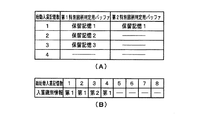
図10(A)は、RAM55の所定領域の設けられている第1特別図柄判定用バッファと第2特別図柄判定用バッファの記憶内容の例を示す説明図である。図10(B)は、RAM55の所定領域に記憶されている入賞識別情報の例を示す説明図である。
FIG. 10A is an explanatory diagram showing an example of the storage contents of the first special symbol determination buffer and the second special symbol determination buffer in which a predetermined area of the
ここでは、図10(A)に示すように、3つの第1始動入賞記憶(保留記憶1〜保留記憶3)と、1つの第2保留始動入賞記憶(保留記憶1)とがあるものとする。
Here, as shown in FIG. 10A, there are three first start winning memories (holding
また、図10(B)に示すように、総始動入賞記憶数1〜4に、それぞれ、「第1」(ここでは始動入賞口14Aへの入賞にもとづく保留記憶であることを意味する)、「第1」、「第2」(ここでは始動入賞口14Bへの入賞にもとづく保留記憶であることを意味する)、「第1」が対応付けされている。従って、総始動入賞記憶数1〜4に対応する保留記憶は、始動入賞口14A、始動入賞口14A、始動入賞口14B、始動入賞口14Aの順番で入賞したことによるものであり、特別図柄の変動表示は、第1特別図柄、第1特別図柄、第2特別図柄、第1特別図柄の順番で実行されることになる。
Further, as shown in FIG. 10B, the total starting winning
図11は、図10に示す保留記憶状態であるときに順次実行される変動表示を説明するための説明図である。図12は、図10に示す保留記憶状態であるときに順次実行される変動表示のタイミングの例を示すタイミングチャートである。なお、ここでは、新たな始動入賞はないものとする。 FIG. 11 is an explanatory diagram for explaining the variable display that is sequentially executed in the reserved storage state shown in FIG. FIG. 12 is a timing chart showing an example of the timing of the variable display that is sequentially executed when in the reserved storage state shown in FIG. Here, it is assumed that there is no new starting prize.
図10に示す保留記憶状態の総始動入賞記憶数が4であるときに、表示制御用CPU101は、先ず、総始動入賞記憶数の表示を1減算した3とし、特別図柄表示器33にて第1特別図柄の変動表示(図12に示す変動表示A)を開始するとともに、可変表示装置9にて変動表示Aに対応した飾り図柄の変動表示(図12に示すA対応表示)を開始する(図11(A))。
When the total start winning memory number in the hold storage state shown in FIG. 10 is 4, the
変動表示AおよびA対応表示が完了すると、表示制御用CPU101は、総始動入賞記憶数の表示を1減算した2とし、特別図柄表示器33にて第1特別図柄の変動表示(図12に示す変動表示B)を開始するとともに、可変表示装置9にて変動表示Bに対応した飾り図柄の変動表示(図12に示すB対応表示)を開始する(図11(B))。
When the variable display A and the A-corresponding display are completed, the
次いで、表示制御用CPU101は、変動表示BおよびB対応表示が開始された後、あらかじめ定められた所定期間を経過すると、総始動入賞記憶数の表示を1減算した1とし、特別図柄表示器39にて第2特別図柄の変動表示(図12に示す変動表示C)を開始する(図11(C))。図11(C)に示すように、この例では、変動表示BおよびB対応表示が完了する前に、変動表示Cが開始される。また、図12に示すように、この例では、変動表示Cが開始された場合であっても、可変表示装置9では、B対応表示が継続して実行される。
Next, after the variable display B and the B-corresponding display are started, the
その後、図12に示すように、変動表示BおよびB対応表示が完了すると、表示制御用CPU101は、可変表示装置9での飾り図柄の変動表示を、B対応表示から、継続して実行されている変動表示Cに対応した飾り図柄の変動表示(図12に示すC対応表示)に切り替える(図11(D))。
After that, as shown in FIG. 12, when the variable display B and the B-corresponding display are completed, the
そして、変動表示CおよびC対応表示が完了すると、表示制御用CPU101は、総始動入賞記憶数の表示を1減算した0とし、特別図柄表示器33にて第1特別図柄の変動表示(図12に示す変動表示D)を開始するとともに、可変表示装置9にて変動表示Dに対応した飾り図柄の変動表示(図12に示すD対応表示)を開始する(図11(E))。その後、表示制御用CPU101は、変動表示DおよびD対応表示を完了させる。
When the variable display C and the C-corresponding display are completed, the
なお、上記の例では、主基板31のCPU56は、図12に示す変動表示Bの指定を行うための変動パターンコマンドを送信したあと、変動表示Bの変動期間が完了する前(例えば所定期間経過後)に、変動表示Cの指定を行うための変動パターンコマンドを送信する処理を実行するように構成すればよい。
In the above example, the
上記のように、第1特別図柄と第2特別図柄とを用いて複数箇所で時間的に重複させて特別図柄の変動表示を行うとともに、第1特別図柄および第2特別図柄の変動表示態様に応じて飾り図柄による演出制御を行う構成としたので、ゲーム性をさらに高めることができるとともに、遊技の内容を遊技者に容易に認識させることができ、遊技の興趣を向上させることができる。 As described above, the first special symbol and the second special symbol are temporally overlapped at a plurality of locations to display the special symbol in a variable manner, and the first special symbol and the second special symbol in a variable display mode. Accordingly, since the effect control by the decorative design is performed, the game performance can be further improved, the game content can be easily recognized by the player, and the entertainment of the game can be improved.
特別図柄の変動表示が複数箇所で時間的に重複して実行されると、遊技者にとっては非常に分かりづらいものとなるおそれがあるが、上記の例では、先に開始された特別図柄の変動表示が完了するまでは、先に開始された特別図柄の変動表示に対応する飾り図柄の変動表示を行うものとし、先に開始された特別図柄の変動表示が完了したときに、後に開始された特別図柄の変動表示に対応する飾り図柄の変動表示に切り替えることとし、特別図柄の変動表示態様に応じた飾り図柄の変動表示を1箇所で実行する構成としているので、遊技者は、変動表示結果などの遊技状態を把握するために、時間的に重複した複数箇所での特別図柄の変動表示を確認する必要がなくなり、飾り図柄だけに注目していればよくなる。すなわち、遊技の内容を遊技者に容易に認識させることができ、遊技の興趣を向上させることができるのである。 If the special symbol variation display is executed in multiple places at the same time, it may be very difficult for the player to understand, but in the above example, the special symbol variation started earlier Until the display is completed, the decorative pattern corresponding to the variable display of the special symbol that was started first will be displayed, and when the variable display of the special symbol that was started first is completed, it will be started later. Since the player is switched to the display of the decorative design corresponding to the display of the special design, and the display of the display of the decorative design corresponding to the display of the special design is performed in one place. In order to grasp the gaming state such as, it is not necessary to confirm the change display of the special symbols at a plurality of locations that overlap in time, and it is only necessary to pay attention to only the decorative symbols. That is, the contents of the game can be easily recognized by the player, and the interest of the game can be improved.
なお、図10〜図12に示した上記の例では特に言及していないが、前に実行される特別図柄の変動表示の変動表示態様や、後に実行される特別図柄の変動表示の変動表示態様にもとづいて、特別図柄の変動表示の変動表示態様を決定する構成としてもよい。 Although not particularly mentioned in the above examples shown in FIGS. 10 to 12, the variation display mode of the variation display of the special symbol executed before and the variation display mode of the variation display of the special symbol performed later On the basis of the above, a configuration may be adopted in which the variation display mode of the variation display of the special symbol is determined.
図13は、1回前に実行される特別図柄の変動表示の変動表示態様にもとづいて、特別図柄の変動表示の変動表示態様を決定する構成とした場合における変動パターン決定処理(図8に示すステップS62の処理)の例を示すフローチャートである。 FIG. 13 shows a variation pattern determination process (shown in FIG. 8) when the variation display mode of the special symbol variation display is determined based on the variation display variation of the special symbol variation display executed once before. It is a flowchart which shows the example of a process of step S62.
変動パターン決定処理において、CPU56は、先ず、変動パターン決定処理を前回実行したときにステップS62dにてRAM55の変動態様履歴記憶領域に記憶された変動表示態様情報を読み出し(ステップS62a)、読み出した変動表示態様情報が示す変動表示態様に対応付けされている変動パターン決定用テーブルを使用テーブルに設定する(ステップS62b)。
In the variation pattern determination process, the
この例では、第1特別図柄についての変動表示態様毎に変動パターン決定用テーブルが用意されているとともに、第2特別図柄についての変動表示態様毎に変動パターン決定用テーブルが用意されている。各変動パターン決定用テーブルには、変動パターン決定用乱数と比較される比較値と、各比較値に対応した変動パターンとが設定されている。 In this example, a variation pattern determination table is prepared for each variation display mode for the first special symbol, and a variation pattern determination table is prepared for each variation display mode for the second special symbol. In each variation pattern determination table, a comparison value to be compared with the variation pattern determination random number and a variation pattern corresponding to each comparison value are set.
ここで、変動表示態様は、変動時間を含む変動パターンを意味する。また、変動表示態様情報は、変動表示態様を示す情報と、変動対象となる特別図柄が第1特別図柄であるか第2特別図柄であるかを示す情報とを含む。 Here, the fluctuation display mode means a fluctuation pattern including a fluctuation time. The variable display mode information includes information indicating the variable display mode and information indicating whether the special symbol to be changed is the first special symbol or the second special symbol.
次いで、CPU56は、設定されている変動パターン決定用テーブルを用いて、ステップS61にてロードした変動パターン決定用乱数カウンタの値と一致する比較値に対応付けされている変動パターンを、特別図柄の変動表示の変動パターンに決定する(ステップS62c)。
Next, the
ステップS62cにて決定される変動パターンは、1回前の特別図柄の変動表示と、今回の特別図柄の変動表示とで、確定表示される順番が入れ替わってしまわないようなものとされる。すなわち、ステップS62bにて、そのような支障が生じないような複数の変動パターンが設けられている変動パターン決定用テーブルが設定される。 The variation pattern determined in step S62c is such that the order of final display is not switched between the variation display of the special symbol one time before and the variation display of the special symbol of this time. That is, in step S62b, a variation pattern determination table in which a plurality of variation patterns that do not cause such a trouble is provided.
具体的には、例えば、前回の特別図柄の変動表示が変動表示B(図12参照)であり、今回の特別図柄の変動表示が変動表示C(図12参照)であるとすると、変動表示Bの確定表示タイミングよりも遅いタイミングで変動表示Cが確定表示されるような変動パターンに決定される。 Specifically, for example, if the previous special symbol fluctuation display is the fluctuation display B (see FIG. 12), and the current special symbol fluctuation display is the fluctuation display C (see FIG. 12), the fluctuation display B The fluctuation pattern is determined such that the fluctuation display C is fixedly displayed at a timing later than the fixed display timing.
そして、CPU56は、今回決定した変動パターンを含む変動表示態様情報をRAM55の変動態様履歴記憶領域に記憶する(ステップS62d)。
Then, the
上記のように、前回変動表示される特別図柄が第1特別図柄であるか第2特別図柄であるかの別と、および前回の変動表示の変動表示態様とにもとづいて、今回の特別図柄の変動表示の変動表示態様を決定する構成とされているので、特別図柄の変動表示の実行(特に確定表示タイミング)の順番が、始動条件が成立した順番に一致するように制御することが容易にできるようになる。すなわち、後に開始された特別図柄の変動表示が、先に完了してしまうことを防止することが容易となる。 As described above, based on whether the special symbol displayed in the previous variation is the first special symbol or the second special symbol, and the variation display mode of the previous variation display, Since it is configured to determine the variation display mode of the variation display, it is easy to control the order of execution of the variation display of the special symbol (particularly the fixed display timing) so that it matches the order in which the starting conditions are satisfied. become able to. That is, it becomes easy to prevent the variation display of the special symbol started later from being completed first.
なお、上記の例において、前回変動表示される特別図柄の変動表示の表示結果をも考慮して、今回の特別図柄の変動表示の変動表示態様を決定するようにしてもよい。この場合、前回変動表示される特別図柄の変動表示の表示結果が大当りとなるときに、大当り演出が終了するまで今回の特別図柄の変動表示を開始させないように決定したり、大当り演出が終了するまでの十分な変動時間(例えば最長期間)の変動パターンとすることに決定したりする構成とすればよい。なお、最長期間とした場合、大当り演出が終了したときに変動期間の強制終了を指定する変動期間短縮コマンドを送信して停止表示する構成とすればよい。このように構成すれば、前回の特別図柄の変動表示結果が大当りとなる場合であっても、特別図柄の変動表示の実行(特に確定表示タイミング)の順番が、始動条件が成立した順番に一致するように制御することが容易にできる。 In the above example, the variation display mode of the variation display of the special symbol this time may be determined in consideration of the display result of the variation display of the special symbol that is variably displayed last time. In this case, when the display result of the variation display of the special symbol that is variably displayed last time is a big hit, it is decided not to start the variation display of the special symbol this time until the big hit effect ends, or the big hit effect ends. It may be determined that the variation pattern has a sufficient variation time (for example, the longest period). In the case where the longest period is set, a variable period shortening command for designating the forced end of the variable period may be transmitted and stopped and displayed when the big hit effect ends. With this configuration, even if the previous special symbol variation display result is a big hit, the execution order of the special symbol variation display (especially the fixed display timing) matches the order in which the starting conditions are satisfied. Can be controlled easily.
また、図10〜図12に示した上記の例では特に言及していないが、前に実行される飾り図柄の変動表示の変動表示態様や、後に実行される飾り図柄の変動表示の変動表示態様にもとづいて、飾り図柄の変動表示の変動表示態様を決定する構成としてもよい。 Although not particularly mentioned in the above examples shown in FIGS. 10 to 12, the variation display mode of the variation display of the decorative symbol executed before, and the variation display mode of the variation display of the decoration symbol performed later. On the basis of the above, a variation display mode of the variation display of the decorative symbol may be determined.
図14は、1回前に実行される飾り図柄の変動表示の変動表示態様にもとづいて、飾り図柄の変動表示の変動表示態様を決定する構成とした場合における飾り図柄変動パターン決定処理(ステップS804:図9に示すステップS804a,ステップS804bの処理)の例を示すフローチャートである。 FIG. 14 shows a decorative pattern variation pattern determination process (step S804) when the variation display mode of the decorative symbol variation display is determined based on the variation display variation of the decorative symbol variation display executed once before. FIG. 10 is a flowchart showing an example of processing in steps S804a and S804b shown in FIG.
飾り図柄変動パターン決定処理において、表示制御用CPU101は、先ず、飾り図柄変動パターン決定処理を前回実行したときにステップS804fにてRAM103の飾り図柄変動態様履歴記憶領域に記憶された飾り図柄変動表示態様情報を読み出し(ステップS804c)、読み出した飾り図柄変動表示態様情報が示す飾り図柄変動表示態様に対応付けされている飾り図柄変動パターン決定用テーブルを使用テーブルに設定する(ステップS804d)。
In the decorative symbol variation pattern determination process, the
この例では、飾り図柄変動表示態様毎に飾り図柄変動パターン決定用テーブルが用意されている。各飾り図柄変動パターン決定用テーブルには、前回の飾り図柄の変動表示の後に続けて実行される飾り図柄の変動表示を示す飾り図柄変動パターンが設定されている。 In this example, a decorative symbol variation pattern determination table is prepared for each decorative symbol variation display mode. In each decorative symbol variation pattern determination table, a decorative symbol variation pattern indicating a variation display of a decorative symbol executed after the previous variation variation display of the decorative symbol is set.
ここで、飾り図柄変動表示態様は、変動時間を含む飾り図柄変動パターンを意味する。また、飾り図柄変動表示態様情報は、飾り図柄変動表示態様を示す情報を含む。 Here, the decorative symbol variation display mode means a decorative symbol variation pattern including a variation time. The decorative symbol variation display mode information includes information indicating the decorative symbol variation display mode.
次いで、表示制御用CPU101は、設定されている飾り図柄変動パターン決定用テーブルを用いて、今回の変動時間に合致する飾り図柄変動パターンを、飾り図柄の変動表示の変動パターンに決定する(ステップS804e)。
Next, the
ステップS804eにて決定される飾り図柄変動パターンは、1回前の飾り図柄の変動表示の後に続けて今回の飾り図柄の変動表示が実行されても、見た目上支障のないようなものとされる。すなわち、ステップS804dにて、そのような支障が生じないような複数の飾り図柄変動パターンが設けられている飾り図柄変動パターン決定用テーブルが設定される。 The decorative pattern variation pattern determined in step S804e is such that even if the decorative pattern variation display of this time is executed after the previous one of the decorative pattern variation display, there is no apparent problem. . That is, in step S804d, a decorative symbol variation pattern determination table in which a plurality of decorative symbol variation patterns that do not cause such trouble is provided.
具体的には、例えば、再変動演出のような表示演出、停止表示されている飾り図柄のいくつかの停止状態を維持した今回の変動表示を開始するようにし、演出が継続しているかのような表示演出、複数回の特別図柄の変動表示に対応する飾り図柄演出において途中で停止表示を行うことなく継続して変動表示を行い最後だけ停止表示する表示演出などのような飾り図柄変動パターンが選択される。 Specifically, for example, display effects such as re-variation effects, and the current variable display that maintains several stopped states of decorative symbols that are stopped are started, and the effects continue There are decorative pattern variation patterns such as a display effect in which a variable display is continuously displayed without a stop display in the middle and a stop display is displayed only at the end in a decorative pattern production corresponding to a variable display of multiple special designs. Selected.
また、ステップS804eにて決定される飾り図柄変動パターンは、今回の飾り図柄の変動表示に対応する特別図柄の変動期間とは必ずしも一致しない変動期間であって、前回の飾り図柄の変動表示に対応する特別図柄の変動表示が完了したときから、今回の飾り図柄の変動表示に対応する特別図柄の変動表示が完了するときまでの変動期間のものとされる。すなわち、ステップS804eにてそのような変動期間の飾り図柄変動パターンが選択される。 Also, the decorative symbol variation pattern determined in step S804e is a variation period that does not necessarily coincide with the special symbol variation period corresponding to the current decorative symbol variation display, and corresponds to the previous decorative symbol variation display. The variation period from when the special symbol variation display to be completed is completed until when the special symbol variation display corresponding to the current decorative symbol variation display is completed. That is, in step S804e, such a decorative pattern variation pattern during the variation period is selected.
具体的には、例えば、対応する前回の特別図柄の変動表示が変動表示B(図12参照)であり、対応する今回の特別図柄の変動表示が変動表示C(図12参照)であるとすると、今回の飾り図柄の変動表示は、変動表示Bの確定表示タイミングから、変動表示Cの確定表示タイミングまでの変動期間であるC対応表示(図12参照)のような変動パターンとされる。 Specifically, for example, if the corresponding previous special symbol fluctuation display is the fluctuation display B (see FIG. 12), and the corresponding current special symbol fluctuation display is the fluctuation display C (see FIG. 12). The variation display of the decorative pattern this time is a variation pattern such as a C correspondence display (see FIG. 12) which is a variation period from the fixed display timing of the variable display B to the fixed display timing of the variable display C.
そして、表示制御用CPU101は、今回決定した飾り図柄変動パターンを含む飾り図柄変動表示態様情報をRAM55の飾り図柄変動態様履歴記憶領域に記憶する(ステップS804f)。
Then, the
上記のように、前に実行される飾り図柄の変動表示の表示態様に応じて、今回の飾り図柄の変動表示の表示態様を決定することができるため、複数回分の特別図柄の変動表示に対応する飾り図柄の変動表示を、1回の変動表示に見せるようにするようなことができるようになり、演出効果を向上させることができる。 As described above, since the display mode of the decorative display of the decorative pattern this time can be determined according to the display mode of the variable display of the decorative pattern executed before, it corresponds to the variable display of special symbols for multiple times. The variation display of the decorative pattern to be displayed can be made to appear as one variation display, and the effect of production can be improved.
図15は、1回後に実行される飾り図柄の変動表示の変動表示態様にもとづいて、飾り図柄の変動表示の変動表示態様を決定する構成とした場合における飾り図柄変動パターン決定処理(ステップS804:図9に示すステップS804a,ステップS804bの処理)の例を示すフローチャートである。 FIG. 15 shows a decorative pattern variation pattern determination process (step S804: FIG. 15) in which the variation display mode of the decorative symbol variation display is determined based on the variation display variation of the decorative symbol variation display executed once after. 10 is a flowchart illustrating an example of steps S804a and S804b illustrated in FIG. 9.
飾り図柄変動パターン決定処理において、表示制御用CPU101は、先ず、1回後に実行される特別図柄の変動表示を指定する変動パターンコマンドにもとづいて、1回後に実行される飾り図柄の変動表示の変動表示態様を判定する(ステップS804h)。すなわち、この例では、1回後に実行される特別図柄の変動表示を指定する変動パターンコマンドがあらかじめ主基板31から送信される構成とし、表示制御基板80にて1回後の特別図柄の変動表示を指定する変動パターンコマンドをあらかじめ受信して保持しておく構成とされる。つまり、この例では、主基板31は、送信済の変動パターンコマンドにもとづく変動表示が開始されていなくても、保留記憶があれば次回の特別図柄の変動表示を指定する変動パターンコマンドを送信する処理を実行する。
In the decorative symbol variation pattern determination process, the
具体的には、例えば3つの保留記憶がある場合には、主基板31のCPU56は、例えば、1回目の特別図柄の変動表示を指定する変動パターンコマンドを送信したあと、表示制御基板80にて1回目の特別図柄の変動表示が開始される前(少なくともステップS804hの処理が開始される前)に、2回目の特別図柄の変動表示を指定する変動パターンコマンドを送信する処理を行うようにすればよい。また、その後に、CPU56は、表示制御基板80にて2回目の特別図柄の変動表示が開始される前(少なくともステップS804hの処理が開始される前)に、3回目の特別図柄の変動表示を指定する変動パターンコマンドを送信する処理を行うようにすればよい。
Specifically, for example, when there are three reserved memories, the
また、表示制御用CPU101は、主基板31から送信された変動パターンコマンドを受信して保持しておき、1回目の特別図柄の変動表示を行うときに、ステップS804hにて、保持している2回目の特別図柄の変動表示を指定する変動パターンコマンドを用いるようにすればよい。また、その後、表示制御用CPU101は、2回目の特別図柄の変動表示を行うときに、ステップS804hにて、保持している3回目の特別図柄の変動表示を指定する変動パターンコマンドを用いるようにすればよい。
Further, the
次いで、表示制御用CPU101は、ステップS804hにて判定した飾り図柄の変動表示の変動表示態様に対応付けされている飾り図柄変動パターン決定用テーブルを使用テーブルに設定する(ステップS804i)。
Next, the
この例では、飾り図柄変動表示態様毎に飾り図柄変動パターン決定用テーブルが用意されている。各飾り図柄変動パターン決定用テーブルには、次回の飾り図柄の変動表示の前に実行される飾り図柄の変動表示を示す飾り図柄変動パターンが設定されている。 In this example, a decorative symbol variation pattern determination table is prepared for each decorative symbol variation display mode. In each decorative symbol variation pattern determination table, a decorative symbol variation pattern indicating a decorative symbol variation display that is executed before the next decorative symbol variation display is set.
そして、表示制御用CPU101は、設定されている飾り図柄変動パターン決定用テーブルを用いて、今回の変動時間に合致する飾り図柄変動パターンを、飾り図柄の変動表示の変動パターンに決定する(ステップS804j)。
Then, the
ステップS804eにて決定される飾り図柄変動パターンは、1回後の飾り図柄の変動表示の前に今回の飾り図柄の変動表示が実行されても、見た目上支障のないようなものとされる。言い換えれば、今回の飾り図柄の変動表示の後に続けて1回後の飾り図柄の変動表示が実行されても、見た目上支障のないようなものとされる。すなわち、ステップS804iにて、そのような支障が生じないような複数の飾り図柄変動パターンが設けられている飾り図柄変動パターン決定用テーブルが設定される。 The decorative symbol variation pattern determined in step S804e is such that even if the current decorative symbol variation display is executed before the decorative symbol variation display one time later, there is no apparent problem. In other words, even if the variation display of the decorative pattern is executed one time after the current variation display of the decorative symbol, there is no apparent problem. That is, in step S804i, a decorative symbol variation pattern determination table in which a plurality of decorative symbol variation patterns that do not cause such trouble is provided.
具体的には、例えば、再変動演出のような表示演出、停止表示する飾り図柄のいくつかが停止状態を維持したまま次回の変動表示が開始される表示演出、停止表示することなく次回の変動表示が開始される表示演出などのような、演出が継続しているかのような表示演出を行う飾り図柄変動パターンが選択される。 Specifically, for example, a display effect such as a re-change effect, a display effect in which the next change display is started while some of the decorative symbols to be stopped are kept stopped, and the next change without being stopped. A decorative design variation pattern that performs a display effect as if the effect continues, such as a display effect that starts display, is selected.
また、ステップS804jにて決定される飾り図柄変動パターンは、今回の飾り図柄の変動表示に対応する特別図柄の変動期間とは必ずしも一致しない変動期間であって、今回の飾り図柄の変動表示に対応する特別図柄の変動表示が開始するときから、次回の飾り図柄の変動表示に対応する特別図柄の変動表示が開始するときまでの変動期間のものとされる。すなわち、ステップS804jにてそのような変動期間の飾り図柄変動パターンが選択される。 Also, the decorative symbol variation pattern determined in step S804j is a variation period that does not necessarily coincide with the special symbol variation period corresponding to the current decorative symbol variation display, and corresponds to the current decorative symbol variation display. The variation period from the start of the special symbol variation display to the time when the special symbol variation display corresponding to the next decorative symbol variation display is started. That is, in step S804j, such a decorative pattern variation pattern during the variation period is selected.
上記のように、後に実行される飾り図柄の変動表示の表示態様に応じて、今回の飾り図柄の変動表示の表示態様を決定する構成としたので、複数回分の特別図柄の変動表示に対応する飾り図柄の変動表示を、1回の変動表示に見せるようにするようなことができるようになり、演出効果を向上させることができる。特に、複数回の飾り図柄の変動表示における先の変動表示の内容を、後の変動表示の内容にもとづいて決定するので、継続して実行されているような表示演出とすることが容易となる。 As described above, since the display mode of the variation display of the decorative symbol this time is determined according to the display mode of the variation display of the decorative symbol executed later, it corresponds to the variation display of the special symbol for a plurality of times. The variation display of the decorative design can be made to appear as one variation display, and the effect of production can be improved. In particular, since the content of the previous variation display in the variation display of the decorative pattern multiple times is determined based on the content of the subsequent variation display, it is easy to obtain a display effect that is continuously executed. .
なお、上述した実施の形態では特に言及していないが、大入賞口を2つ設ける構成とし、第1特別図柄の変動表示によって大当りとなったときと、第2特別図柄の変動表示によって大当りとなったときとで、大当り遊技において開放される大入賞口を別個のものとするように構成されていてもよい。 Although not particularly mentioned in the above-described embodiment, it is configured to provide two big prize openings, and when the big win is obtained by the variable display of the first special symbol, and when the big special is displayed by the variable display of the second special symbol. It may be configured such that the big winning opening that is opened in the big hit game is made separate.
また、上述した実施の形態では2つの特別図柄表示器33,39により第1特別図柄と第2特別図柄とで特別図柄の変動表示を行う構成としていたが、特別図柄表示器を3つ以上設け、三箇所以上で特別図柄の変動表示を行う構成としてもよい。
In the above-described embodiment, the special symbol display is changed by the two
また、上述した実施の形態では始動入賞が発生した順番に変動表示が実行されることとしていたが、2つの特別図柄表示器33,39による第1特別図柄の変動表示と第2特別図柄の変動表示とに優先順位を設け、優先順位の高い方の保留記憶を優先的に消化するようにしてもよい。具体的には、例えば第2特別図柄の変動表示が、第1特別図柄の変動表示よりも優先度が高く設定されており、第1始動入賞記憶数が「3」で、第2始動入賞記憶数が「2」である場合には、どのような順番で始動入賞が発生したかに関わらず、2回の第2特別図柄の変動表示を優先的に実行し、その後に3回の第1特別図柄の変動表示を実行する。なお、優先度ではなく、特別図柄の変動表示を実行するときに、抽選を行い、第1特別図柄の変動表示と第2特別図柄の変動表示とのいずれを行うかを決定するようにしてもよい。
In the above-described embodiment, the variable display is executed in the order in which the start winnings are generated. However, the first special symbol change display and the second special symbol change by the two
また、上述した実施の形態では2つの特別図柄表示器33,39と、可変表示装置9とを別個に備え、第1特別図柄、第2特別図柄、飾り図柄をそれぞれ別個の表示器で変動表示する構成としていたが、第1特別図柄、第2特別図柄、飾り図柄のうちの任意の2つ、あるいは第1特別図柄、第2特別図柄および飾り図柄の3つを同じ表示器で変動表示する構成とされていてもよい。すなわち、1つの表示器に、第1特別図柄を変動表示する表示部と、第2特別図柄を変動表示する表示部と、飾り図柄を変動表示する表示部とを備えるような構成としてもよい。 In the embodiment described above, the two special symbol displays 33 and 39 and the variable display device 9 are separately provided, and the first special symbol, the second special symbol, and the decorative symbol are variably displayed on the separate indicators. However, any two of the first special symbol, the second special symbol, and the decorative symbol, or the first special symbol, the second special symbol, and the decorative symbol are variably displayed on the same display. It may be configured. That is, it is good also as a structure provided with the display part which variably displays a 1st special symbol, the display part which variably displays a 2nd special symbol, and the display part which variably displays a decoration symbol in one display.
なお、上述した実施の形態では、以下の遊技機も開示されている。
保留記憶数表示手段が、第1の保留記憶手段が記憶している保留記憶であるか第2の保留記憶手段が記憶している保留記憶であるかを区別不能に総保留数特定表示を行う(具体的には図11参照)遊技機。すなわち、始動入賞口14Aへの入賞による保留記憶であるか、始動入賞口14Bへの入賞による保留記憶であるかを区別することなく、始動記憶数表示エリア18に総始動入賞記憶数を表示する構成としている。このように構成されているので、遊技者に総保留記憶数を容易に認識させることができる。
In the above-described embodiment, the following gaming machines are also disclosed.
The hold memory number display means displays the total hold number indistinguishably whether it is the hold memory stored in the first hold memory means or the hold memory stored in the second hold storage means. (See FIG. 11 for details) A gaming machine. That is, the total start winning memory number is displayed in the starting memorized
なお、上記の各実施の形態の遊技機は、始動入賞にもとづいて可変表示装置9に可変表示される特別図柄の停止図柄が所定の図柄の組み合わせになると所定の遊技価値が遊技者に付与可能になる第1種パチンコ遊技機であり、かつ、プリペイドカードによって球貸しを行うカードリーダ(CR:Card Reader )式の第1種パチンコ遊技機であったが、プリペイドカードによって球貸しを行うCR式パチンコ遊技機だけでなく、現金によって球貸しを行うパチンコ遊技機にも適用可能である。さらに、始動入賞にもとづいて開放する電動役物の所定領域への入賞があると所定の遊技価値が遊技者に付与可能になる第2種パチンコ遊技機や、始動入賞にもとづいて可変表示される図柄の停止図柄が所定の図柄の組み合わせになると開放する所定の電動役物への入賞があると所定の権利が発生または継続する第3種パチンコ遊技機であっても、本発明を適用できる。 Note that the gaming machine of each of the above embodiments can give a predetermined game value to a player when a special symbol stop symbol variably displayed on the variable display device 9 based on the start winning combination is a combination of the predetermined symbols. The first type of pachinko gaming machine that becomes a card reader (CR: Card Reader) type lending ball with a prepaid card, but the CR type that lends a ball with a prepaid card It is applicable not only to pachinko machines but also to pachinko machines that lend balls with cash. Furthermore, when there is a winning in a predetermined area of the electric game that is released based on the start winning, a second type pachinko gaming machine that can give a predetermined game value to the player, or variably displayed based on the starting winning The present invention can be applied even to a third-class pachinko gaming machine in which a predetermined right is generated or continues when a winning is made for a predetermined electric combination that is released when the symbol stop symbol becomes a predetermined symbol combination.
また、上記の各実施の形態において、「特別遊技状態」とは、大当りとなりやすい遊技者にとって有利な状態を意味する。具体的には、「特別遊技状態」は、例えば、特別図柄が大当り図柄で揃う確率が高確率状態とされる確変状態、単位時間あたりの普通図柄の変動回数が高められる時短状態、可変入賞球装置15A,15Bの開成期間や開成回数が高められる開放延長状態などの大当りとなる確率が高められている高確率状態である。なお、時短状態は、可変入賞球装置15,15Bの開放回数が高められていることから単位時間あたりの入賞回数が増加し、単位時間あたりの特別図柄の可変表示回数が高められるので、大当りとなる確率が高められている状態といえる。また、同様に、開放延長状態は、可変入賞球装置15,15Bの開成期間や開成回数が高められていることから単位時間あたりの入賞回数が増加し、単位時間あたりの特別図柄の可変表示回数が高められるので、大当りとなる確率が高められている状態といえる。
In each of the above embodiments, the “special game state” means a state advantageous to a player who is likely to make a big hit. Specifically, the “special game state” includes, for example, a probability variation state in which the probability that a special symbol is a big hit symbol is a high probability state, a short time state in which the number of fluctuations of a normal symbol per unit time is increased, a variable winning ball This is a high-probability state in which the probability of a big hit such as an open extension state in which the
本発明は、パチンコ遊技機などの遊技に適用可能であり、特に、識別情報の変動表示を行う表示領域が複数設けられた遊技機において、ゲーム性を高めるとともに、遊技の内容を遊技者に容易に認識させるようにして、遊技の興趣を向上させるために有用である。 The present invention can be applied to a game such as a pachinko game machine, and in particular, in a game machine provided with a plurality of display areas for performing variable display of identification information, the game performance is improved and the contents of the game can be easily made to the player. It is useful to improve the fun of the game.
1 パチンコ遊技機
9 可変表示装置
14a,14b 始動口スイッチ
15A,15B 可変入賞球装置
31 主基板
33,39 特別図柄表示器
56 CPU
80 表示制御基板
101 表示制御用CPU
1 Pachinko machine 9
80
Claims (3)
前記第1の始動条件が成立したことにもとづいて第1の識別情報の変動時間を特定可能な変動表示態様を決定し、前記第2の始動条件が成立したことにもとづいて第2の識別情報の変動時間を特定可能な変動表示態様を決定する特別変動表示態様決定手段と、
前記特別変動表示態様決定手段が決定した変動表示態様を記憶する変動表示態様記憶手段と、
前記特別変動表示態様決定手段により決定された第1の識別情報の変動表示態様にもとづいて、第1の変動表示部にて第1の識別情報の変動表示を行わせる第1の変動表示制御手段と、
前記特別変動表示態様決定手段により決定された第2の識別情報の変動表示態様にもとづいて、第2の変動表示部にて第2の識別情報の変動表示を行わせる第2の変動表示制御手段と、
前記第1の始動条件は成立したが未だ前記開始条件が成立していない変動表示の開始をあらかじめ定められている第1の上限数まで保留記憶する第1の保留記憶手段と、
前記第2の始動条件は成立したが未だ前記開始条件が成立していない変動表示の開始をあらかじめ定められている第2の上限数まで保留記憶する第2の保留記憶手段と、
第1の識別情報および第2の識別情報の変動表示態様にもとづいて、第1の識別情報および第2の識別情報の変動表示態様に対応する第3の識別情報の変動時間を特定可能な飾り変動表示態様を決定する飾り変動表示態様決定手段と、
前記飾り変動表示態様決定手段が決定した飾り変動表示態様を記憶する飾り変動表示態様記憶手段と、
前記飾り変動表示態様決定手段により決定された第3の識別情報の飾り変動表示態様にもとづいて、第1の識別情報の変動表示と第2の識別情報の変動表示の開始と停止に対応して第3の変動表示部にて1箇所での第3の識別情報の変動表示の開始と停止を行わせる第3の変動表示制御手段と、
前記第1の保留記憶手段が記憶している保留数と前記第2の保留記憶手段が記憶している保留数との総数である総保留数が特定可能な総保留数特定表示を行う保留記憶数表示手段と、を備え、
前記第1の変動表示制御手段および前記第2の変動表示制御手段は、第1の識別情報と第2の識別情報のいずれか一方の変動表示が行われているときに、変動表示が行われていない他方の識別情報の開始条件が成立した場合、変動表示が行われている一方の識別情報の変動表示の停止を待たずに他方の識別情報の変動表示が開始されることにより第1の識別情報と第2の識別情報とが同時に変動表示可能であり、
前記特別変動表示態様決定手段は、前記変動表示態様記憶手段が記憶している既に決定された変動表示態様にもとづいて、後に変動表示が開始された他方の識別情報の変動表示が先に変動表示が開始された一方の識別情報の変動表示よりも後に停止する他方の識別情報の変動表示態様を決定し、
前記飾り変動表示態様決定手段は、前記飾り変動表示態様記憶手段が記憶している既に決定された飾り変動表示態様にもとづいて、第1の識別情報と第2の識別情報とが同時に変動表示している場合において、同時に変動表示が行われたのち第1の識別情報と第2の識別情報のいずれか一方の変動表示が停止したときから、未だ変動表示が行われている他方の識別情報の変動表示が停止するときまでの残り変動時間に対応させて飾り変動表示態様を決定する
ことを特徴とする遊技機。 After the player plays a game by launching the game medium into the game area, and the predetermined first start condition or the second start condition is satisfied, each of them is determined based on the start condition of the variable display. The player starts the variable display of the identifiable first identification information or the second identification information, and the display result of the variable display of the first identification information or the second identification information becomes the specific display result. A gaming machine that can be controlled to a specific gaming state advantageous to
A variation display mode capable of specifying a variation time of the first identification information is determined based on the establishment of the first start condition, and the second identification information is determined based on the establishment of the second start condition. Special fluctuation display mode determining means for determining a fluctuation display mode capable of specifying the fluctuation time of
Fluctuation display mode storage means for storing the fluctuation display mode determined by the special fluctuation display mode determination means;
First variation display control means for causing the first variation display section to perform variation display of the first identification information based on the variation display mode of the first identification information determined by the special variation display mode determination unit. When,
Second variation display control means for causing the second variation display section to perform variation display of the second identification information based on the variation display mode of the second identification information determined by the special variation display mode determination means. When,
First holding storage means for holding and storing up to a predetermined first upper limit number of variable displays in which the first start condition is satisfied but the start condition is not yet satisfied;
A second holding storage means for holding the start of the variable display in which the second start condition is satisfied but the start condition is not yet satisfied up to a predetermined second upper limit number;
A decoration that can specify the variation time of the third identification information corresponding to the variation display mode of the first identification information and the second identification information based on the variation display mode of the first identification information and the second identification information. A decoration variation display mode determining means for determining a variation display mode;
Decoration variation display mode storage means for storing the decoration variation display mode determined by the decoration variation display mode determination means;
Based on the decoration variation display mode of the third identification information determined by the decoration variation display mode determination means , corresponding to the start and stop of the variation display of the first identification information and the variation display of the second identification information Third variation display control means for causing the third variation display section to start and stop the variation display of the third identification information at one location ;
Pending storage for displaying the total number of holdings that can specify the total number of holdings, which is the total number of holdings stored in the first holding storage unit and the number of holdings stored in the second holding storage unit. A number display means,
The first variation display control unit and the second variation display control unit perform variation display when variation display of any one of the first identification information and the second identification information is performed. If the start condition of the other identification information that has not been established is satisfied, the first display of the variation of the other identification information is started without waiting for the suspension of the variation display of the one identification information being displayed. The identification information and the second identification information can be variably displayed at the same time,
The special variation display mode determining means is configured to display the variation display of the other identification information whose variation display is started later based on the already determined variation display mode stored in the variation display mode storage unit. Determining the variation display mode of the other identification information that stops after the variation display of the one identification information started,
The decoration variation display mode determining means displays the first identification information and the second identification information in a variable manner based on the already determined decoration variation display mode stored in the decoration variation display mode storage unit. In this case, since the variable display of either one of the first identification information and the second identification information is stopped after the variable display is performed at the same time, the other identification information for which the variable display is still performed is displayed. A game machine characterized in that a decoration variation display mode is determined in accordance with a remaining variation time until the variation display stops .
前記第1の始動検出手段とは異なり、前記遊技領域に設けられた第2の始動入賞領域を遊技媒体が通過したことを検出する第2の始動検出手段と、
第1の始動入賞領域の遊技媒体の通過を前記第1の始動検出手段が検出したことにもとづいて第1の始動条件が成立したと判定する第1始動条件判定手段と、
第2の始動入賞領域の遊技媒体の通過を前記第2の始動検出手段が検出したことにもとづいて第2の始動条件が成立したと判定する第2始動条件判定手段と、を備えた
請求項1記載の遊技機。 First start detecting means for detecting that the game medium has passed through a first start winning area provided in the game area;
Unlike the first start detection means, second start detection means for detecting that a game medium has passed through a second start winning area provided in the game area;
First start condition determining means for determining that the first start condition is established based on the fact that the first start detecting means detects passage of the game medium in the first start winning area;
And a second start condition determining means for determining that the second start condition is established based on the fact that the second start detecting means detects the passage of the game medium in the second start winning area. The gaming machine according to 1 .
特定確率記憶手段は、前記第1決定確率とは異なる確率の前記第2決定確率を記憶する
請求項1または請求項2記載の遊技機。 A first determination probability as to whether or not the display result of the variation display of the first identification information is the specific display result, and a second as to whether or not the display result of the variation display of the second identification information is the specific display result A specific probability storage means for storing a determination probability;
Particular probability storage means according to claim 1 or claim 2 gaming machine according storing said second decision probability of the different probabilities from the first decision probability.
Priority Applications (1)
| Application Number | Priority Date | Filing Date | Title |
|---|---|---|---|
| JP2003365356A JP4188202B2 (en) | 2003-10-24 | 2003-10-24 | Game machine |
Applications Claiming Priority (1)
| Application Number | Priority Date | Filing Date | Title |
|---|---|---|---|
| JP2003365356A JP4188202B2 (en) | 2003-10-24 | 2003-10-24 | Game machine |
Related Child Applications (1)
| Application Number | Title | Priority Date | Filing Date |
|---|---|---|---|
| JP2007122497A Division JP4463839B2 (en) | 2007-05-07 | 2007-05-07 | Game machine |
Publications (3)
| Publication Number | Publication Date |
|---|---|
| JP2005124939A JP2005124939A (en) | 2005-05-19 |
| JP2005124939A5 JP2005124939A5 (en) | 2007-06-21 |
| JP4188202B2 true JP4188202B2 (en) | 2008-11-26 |
Family
ID=34644042
Family Applications (1)
| Application Number | Title | Priority Date | Filing Date |
|---|---|---|---|
| JP2003365356A Expired - Fee Related JP4188202B2 (en) | 2003-10-24 | 2003-10-24 | Game machine |
Country Status (1)
| Country | Link |
|---|---|
| JP (1) | JP4188202B2 (en) |
Families Citing this family (175)
| Publication number | Priority date | Publication date | Assignee | Title |
|---|---|---|---|---|
| JP4601715B2 (en) * | 2003-12-24 | 2010-12-22 | 株式会社ソフイア | Game machine |
| JP4491227B2 (en) * | 2003-12-24 | 2010-06-30 | 株式会社ソフイア | Game machine |
| JP2005342249A (en) * | 2004-06-03 | 2005-12-15 | Samii Kk | Pinball machine |
| JP4544516B2 (en) * | 2004-06-28 | 2010-09-15 | サミー株式会社 | Bullet ball machine |
| JP5067915B2 (en) * | 2005-06-14 | 2012-11-07 | サミー株式会社 | Bullet ball machine |
| JP4914032B2 (en) * | 2005-06-27 | 2012-04-11 | 株式会社大一商会 | Game machine |
| JP2007007105A (en) * | 2005-06-29 | 2007-01-18 | Samii Kk | Pinball game machine |
| JP2007007106A (en) * | 2005-06-29 | 2007-01-18 | Samii Kk | Pinball game machine |
| JP4993161B2 (en) * | 2005-07-11 | 2012-08-08 | サミー株式会社 | Bullet ball machine |
| JP4993160B2 (en) * | 2005-07-11 | 2012-08-08 | サミー株式会社 | Bullet ball machine |
| JP5143343B2 (en) * | 2005-07-21 | 2013-02-13 | 株式会社藤商事 | Bullet ball machine |
| JP2007029256A (en) * | 2005-07-25 | 2007-02-08 | Daiichi Shokai Co Ltd | Game machine |
| JP2007029242A (en) * | 2005-07-25 | 2007-02-08 | Daiichi Shokai Co Ltd | Game machine |
| JP4844953B2 (en) * | 2005-07-26 | 2011-12-28 | 株式会社大一商会 | Game machine |
| JP4947537B2 (en) * | 2005-10-21 | 2012-06-06 | サミー株式会社 | Pachinko machine |
| JP2007111374A (en) * | 2005-10-21 | 2007-05-10 | Samii Kk | Pachinko game machine |
| JP4986011B2 (en) * | 2005-10-21 | 2012-07-25 | サミー株式会社 | Pachinko machine |
| JP2007111375A (en) * | 2005-10-21 | 2007-05-10 | Samii Kk | Pachinko game machine |
| JP4730896B2 (en) * | 2005-10-28 | 2011-07-20 | サミー株式会社 | Bullet ball machine |
| JP4840761B2 (en) * | 2005-12-01 | 2011-12-21 | 株式会社大一商会 | Game machine |
| JP4840759B2 (en) * | 2005-12-01 | 2011-12-21 | 株式会社大一商会 | Game machine |
| JP4840762B2 (en) * | 2005-12-01 | 2011-12-21 | 株式会社大一商会 | Game machine |
| JP4840760B2 (en) * | 2005-12-01 | 2011-12-21 | 株式会社大一商会 | Game machine |
| JP5033946B2 (en) * | 2005-12-01 | 2012-09-26 | 株式会社大一商会 | Game machine |
| JP2007151814A (en) * | 2005-12-05 | 2007-06-21 | Daikoku Denki Co Ltd | Pachinko game machine |
| JP4756502B2 (en) * | 2005-12-13 | 2011-08-24 | 株式会社大一商会 | Game machine |
| JP4808487B2 (en) * | 2005-12-15 | 2011-11-02 | 株式会社三共 | Game machine |
| JP4808486B2 (en) * | 2005-12-15 | 2011-11-02 | 株式会社三共 | Game machine |
| JP4895165B2 (en) * | 2005-12-22 | 2012-03-14 | 奥村遊機株式会社 | Pachinko machine |
| JP2007167567A (en) * | 2005-12-26 | 2007-07-05 | Daiichi Shokai Co Ltd | Pachinko game machine |
| JP2007185306A (en) * | 2006-01-12 | 2007-07-26 | Taiyo Elec Co Ltd | Pinball game machine |
| JP5207503B2 (en) * | 2006-01-27 | 2013-06-12 | サミー株式会社 | Bullet ball machine |
| JP5080746B2 (en) * | 2006-03-28 | 2012-11-21 | 株式会社三共 | Game machine |
| JP4571091B2 (en) * | 2006-03-29 | 2010-10-27 | 株式会社三共 | Game machine |
| JP4571092B2 (en) * | 2006-03-29 | 2010-10-27 | 株式会社三共 | Game machine |
| JP4619974B2 (en) * | 2006-03-29 | 2011-01-26 | 株式会社三共 | Game machine |
| JP5101035B2 (en) * | 2006-04-24 | 2012-12-19 | 株式会社三共 | Game machine |
| JP2007289523A (en) * | 2006-04-26 | 2007-11-08 | Sankyo Kk | Game machine |
| JP2007295945A (en) * | 2006-04-27 | 2007-11-15 | Sankyo Kk | Game machine |
| JP2007295944A (en) * | 2006-04-27 | 2007-11-15 | Sankyo Kk | Game machine |
| JP4584183B2 (en) * | 2006-04-28 | 2010-11-17 | 株式会社三共 | Game machine |
| JP4531721B2 (en) * | 2006-04-28 | 2010-08-25 | 株式会社三共 | Game machine |
| JP4584182B2 (en) * | 2006-04-28 | 2010-11-17 | 株式会社三共 | Game machine |
| JP5024508B2 (en) * | 2006-04-30 | 2012-09-12 | 株式会社大一商会 | Game machine |
| JP4909629B2 (en) * | 2006-04-30 | 2012-04-04 | 株式会社大一商会 | Game machine |
| JP4909630B2 (en) * | 2006-04-30 | 2012-04-04 | 株式会社大一商会 | Game machine |
| JP4909628B2 (en) * | 2006-04-30 | 2012-04-04 | 株式会社大一商会 | Game machine |
| JP4909627B2 (en) * | 2006-04-30 | 2012-04-04 | 株式会社大一商会 | Game machine |
| JP4909631B2 (en) * | 2006-04-30 | 2012-04-04 | 株式会社大一商会 | Game machine |
| JP5367213B2 (en) * | 2006-05-12 | 2013-12-11 | 株式会社三洋物産 | Game machine |
| JP4909634B2 (en) * | 2006-05-14 | 2012-04-04 | 株式会社大一商会 | Game machine |
| JP5044752B2 (en) * | 2006-05-14 | 2012-10-10 | 株式会社大一商会 | Game machine |
| JP4909636B2 (en) * | 2006-05-14 | 2012-04-04 | 株式会社大一商会 | Game machine |
| JP4909635B2 (en) * | 2006-05-14 | 2012-04-04 | 株式会社大一商会 | Game machine |
| JP5122087B2 (en) * | 2006-05-26 | 2013-01-16 | 株式会社三共 | Game machine |
| JP2007319267A (en) * | 2006-05-30 | 2007-12-13 | Okumura Yu-Ki Co Ltd | Game machine |
| JP2007319277A (en) * | 2006-05-30 | 2007-12-13 | Okumura Yu-Ki Co Ltd | Game machine |
| JP2007319269A (en) * | 2006-05-30 | 2007-12-13 | Okumura Yu-Ki Co Ltd | Game machine |
| JP2007319270A (en) * | 2006-05-30 | 2007-12-13 | Okumura Yu-Ki Co Ltd | Game machine |
| JP2007319274A (en) * | 2006-05-30 | 2007-12-13 | Okumura Yu-Ki Co Ltd | Game machine |
| JP4808549B2 (en) * | 2006-06-02 | 2011-11-02 | 株式会社三共 | Game machine |
| JP4842020B2 (en) * | 2006-06-02 | 2011-12-21 | 株式会社三共 | Game machine |
| JP4808548B2 (en) * | 2006-06-02 | 2011-11-02 | 株式会社三共 | Game machine |
| JP4813268B2 (en) * | 2006-06-30 | 2011-11-09 | 高砂電器産業株式会社 | Game machine |
| JP4499068B2 (en) * | 2006-07-05 | 2010-07-07 | 株式会社三共 | Game machine |
| JP5211454B2 (en) * | 2006-09-01 | 2013-06-12 | 株式会社三洋物産 | Game machine |
| JP4511501B2 (en) * | 2006-09-25 | 2010-07-28 | 株式会社三共 | Game machine |
| JP2008086499A (en) * | 2006-09-29 | 2008-04-17 | Aruze Corp | Game machine |
| JP2008099955A (en) * | 2006-10-20 | 2008-05-01 | Fujishoji Co Ltd | Pinball game machine |
| JP4906089B2 (en) * | 2006-11-13 | 2012-03-28 | 株式会社ニューギン | Game machine |
| JP4896676B2 (en) * | 2006-11-15 | 2012-03-14 | 株式会社ニューギン | Game machine |
| JP4514744B2 (en) * | 2006-11-24 | 2010-07-28 | 株式会社三共 | Game machine |
| JP4514745B2 (en) * | 2006-11-24 | 2010-07-28 | 株式会社三共 | Game machine |
| JP2008136768A (en) * | 2006-12-05 | 2008-06-19 | Fujishoji Co Ltd | Pinball game machine |
| JP2008167873A (en) * | 2007-01-10 | 2008-07-24 | Aruze Corp | Pinball game machine |
| JP4519144B2 (en) * | 2007-01-22 | 2010-08-04 | 株式会社三共 | Game machine |
| JP4519145B2 (en) * | 2007-01-26 | 2010-08-04 | 株式会社三共 | Game machine |
| JP4584273B2 (en) * | 2007-02-13 | 2010-11-17 | 株式会社三共 | Game machine |
| JP2008220792A (en) * | 2007-03-15 | 2008-09-25 | Daito Giken:Kk | Game machine |
| JP5593531B2 (en) * | 2007-03-15 | 2014-09-24 | 株式会社大都技研 | Amusement stand |
| JP4674772B2 (en) * | 2007-03-28 | 2011-04-20 | サミー株式会社 | Pachinko machine |
| JP4607141B2 (en) * | 2007-03-29 | 2011-01-05 | 株式会社三共 | Game machine |
| JP4635019B2 (en) * | 2007-04-03 | 2011-02-16 | 株式会社三共 | Game machine |
| JP4574637B2 (en) * | 2007-04-04 | 2010-11-04 | 株式会社三共 | Game machine |
| JP4635021B2 (en) * | 2007-04-04 | 2011-02-16 | 株式会社三共 | Game machine |
| JP4635022B2 (en) * | 2007-04-04 | 2011-02-16 | 株式会社三共 | Game machine |
| JP4635024B2 (en) * | 2007-04-10 | 2011-02-16 | 株式会社三共 | Game machine |
| JP5075479B2 (en) * | 2007-05-25 | 2012-11-21 | 株式会社三共 | Game machine |
| JP2008295952A (en) * | 2007-06-04 | 2008-12-11 | Olympia:Kk | Game machine, program, and record medium |
| JP4726864B2 (en) * | 2007-06-28 | 2011-07-20 | 株式会社三共 | Game machine |
| JP4753317B2 (en) * | 2007-08-24 | 2011-08-24 | サミー株式会社 | Bullet ball machine |
| JP4753318B2 (en) * | 2007-09-03 | 2011-08-24 | サミー株式会社 | Bullet ball machine |
| JP5452855B2 (en) * | 2007-09-10 | 2014-03-26 | 株式会社平和 | Game machine |
| JP5277406B2 (en) * | 2007-09-26 | 2013-08-28 | 株式会社大一商会 | Game machine |
| JP5007190B2 (en) * | 2007-09-28 | 2012-08-22 | 株式会社三共 | Game machine |
| JP2009142494A (en) * | 2007-12-14 | 2009-07-02 | Aruze Corp | Pinball game machine |
| JP5232958B2 (en) * | 2008-02-12 | 2013-07-10 | 株式会社高尾 | Bullet ball machine |
| JP5358805B2 (en) * | 2008-02-29 | 2013-12-04 | 豊丸産業株式会社 | Game machine |
| JP5385550B2 (en) * | 2008-05-16 | 2014-01-08 | 株式会社ニューギン | Game machine |
| JP2010035737A (en) * | 2008-08-04 | 2010-02-18 | Taiyo Elec Co Ltd | Game machine |
| JP5266946B2 (en) * | 2008-08-07 | 2013-08-21 | 株式会社三洋物産 | Game machine |
| JP5226451B2 (en) * | 2008-10-07 | 2013-07-03 | ダイコク電機株式会社 | Pachinko machine |
| JP4832497B2 (en) * | 2008-11-19 | 2011-12-07 | 株式会社高尾 | Bullet ball machine |
| JP5255414B2 (en) * | 2008-12-01 | 2013-08-07 | マルホン工業株式会社 | Pachinko machine |
| JP5263961B2 (en) * | 2009-02-18 | 2013-08-14 | サミー株式会社 | Pachinko machine |
| JP4668325B2 (en) * | 2009-03-13 | 2011-04-13 | 株式会社三共 | Game machine |
| JP4668326B2 (en) * | 2009-03-13 | 2011-04-13 | 株式会社三共 | Game machine |
| JP4808263B2 (en) * | 2009-03-17 | 2011-11-02 | 株式会社三共 | Game machine |
| JP4854762B2 (en) * | 2009-05-18 | 2012-01-18 | 株式会社藤商事 | Bullet ball machine |
| JP5143786B2 (en) * | 2009-05-29 | 2013-02-13 | 株式会社藤商事 | Bullet ball machine |
| JP2009202023A (en) * | 2009-06-17 | 2009-09-10 | Sankyo Co Ltd | Game machine |
| JP4808268B2 (en) * | 2009-06-17 | 2011-11-02 | 株式会社三共 | Game machine |
| JP2009202024A (en) * | 2009-06-17 | 2009-09-10 | Sankyo Co Ltd | Game machine |
| JP5145312B2 (en) * | 2009-11-12 | 2013-02-13 | 株式会社ソフイア | Game machine |
| JP2010075763A (en) * | 2010-01-14 | 2010-04-08 | Fujishoji Co Ltd | Pinball game machine |
| JP4833347B2 (en) * | 2010-04-02 | 2011-12-07 | 株式会社三共 | Game machine |
| JP4786754B2 (en) * | 2010-04-07 | 2011-10-05 | 株式会社三共 | Game machine |
| JP4786755B2 (en) * | 2010-04-07 | 2011-10-05 | 株式会社三共 | Game machine |
| JP2010207651A (en) * | 2010-07-02 | 2010-09-24 | Sammy Corp | Pinball game machine |
| JP4730921B2 (en) * | 2010-07-02 | 2011-07-20 | サミー株式会社 | Bullet ball machine |
| JP4730922B2 (en) * | 2010-07-02 | 2011-07-20 | サミー株式会社 | Bullet ball machine |
| JP4730923B2 (en) * | 2010-07-02 | 2011-07-20 | サミー株式会社 | Bullet ball machine |
| JP5386680B2 (en) * | 2010-08-06 | 2014-01-15 | 株式会社高尾 | Bullet ball machine |
| JP5334329B2 (en) * | 2010-09-08 | 2013-11-06 | サミー株式会社 | Bullet ball machine |
| JP4932023B2 (en) * | 2010-09-29 | 2012-05-16 | 株式会社三共 | Game machine |
| JP5068850B2 (en) * | 2010-10-08 | 2012-11-07 | 株式会社三共 | Game machine |
| JP5145441B2 (en) * | 2011-05-12 | 2013-02-20 | 株式会社ソフイア | Game machine |
| JP5051737B2 (en) * | 2011-05-19 | 2012-10-17 | サミー株式会社 | Bullet ball machine |
| JP5145442B2 (en) * | 2011-06-03 | 2013-02-20 | 株式会社ソフイア | Game machine |
| JP5189190B2 (en) * | 2011-07-13 | 2013-04-24 | 株式会社三共 | Game machine |
| JP5189189B2 (en) * | 2011-07-13 | 2013-04-24 | 株式会社三共 | Game machine |
| JP5223161B2 (en) * | 2011-08-05 | 2013-06-26 | 株式会社ソフイア | Game machine |
| JP5311514B2 (en) * | 2011-08-12 | 2013-10-09 | 株式会社大一商会 | Game machine |
| JP5311513B2 (en) * | 2011-08-12 | 2013-10-09 | 株式会社大一商会 | Game machine |
| JP5311512B2 (en) * | 2011-08-12 | 2013-10-09 | 株式会社大一商会 | Game machine |
| JP5068881B2 (en) * | 2011-09-02 | 2012-11-07 | 株式会社三共 | Game machine |
| JP5385956B2 (en) * | 2011-09-12 | 2014-01-08 | 株式会社藤商事 | Bullet ball machine |
| JP5184686B2 (en) * | 2011-10-05 | 2013-04-17 | 株式会社三共 | Game machine |
| JP5671433B2 (en) * | 2011-10-11 | 2015-02-18 | 株式会社大一商会 | Game machine |
| JP5756936B2 (en) * | 2011-10-11 | 2015-07-29 | 株式会社大一商会 | Game machine |
| JP5497727B2 (en) * | 2011-12-16 | 2014-05-21 | 株式会社藤商事 | Bullet ball machine |
| JP5257908B2 (en) * | 2011-12-27 | 2013-08-07 | サミー株式会社 | Bullet ball machine |
| JP6190095B2 (en) * | 2011-12-28 | 2017-08-30 | 株式会社三共 | Game machine |
| JP5565423B2 (en) * | 2012-02-13 | 2014-08-06 | 株式会社三洋物産 | Game machine |
| JP5362870B2 (en) * | 2012-03-22 | 2013-12-11 | 株式会社三共 | Game machine |
| JP5362872B2 (en) * | 2012-03-22 | 2013-12-11 | 株式会社三共 | Game machine |
| JP5362868B2 (en) * | 2012-03-22 | 2013-12-11 | 株式会社三共 | Game machine |
| JP5362871B2 (en) * | 2012-03-22 | 2013-12-11 | 株式会社三共 | Game machine |
| JP5362869B2 (en) * | 2012-03-22 | 2013-12-11 | 株式会社三共 | Game machine |
| JP5362873B2 (en) * | 2012-03-22 | 2013-12-11 | 株式会社三共 | Game machine |
| JP5352699B2 (en) * | 2012-03-29 | 2013-11-27 | 株式会社三共 | Game machine |
| JP5352698B2 (en) * | 2012-03-29 | 2013-11-27 | 株式会社三共 | Game machine |
| JP5661674B2 (en) * | 2012-03-29 | 2015-01-28 | 株式会社三共 | Game machine |
| JP5666499B2 (en) * | 2012-03-29 | 2015-02-12 | 株式会社三共 | Game machine |
| JP5604485B2 (en) * | 2012-08-28 | 2014-10-08 | 株式会社平和 | Game machine |
| JP2012245378A (en) * | 2012-09-14 | 2012-12-13 | Fujishoji Co Ltd | Pinball game machine |
| JP5763698B2 (en) * | 2013-03-13 | 2015-08-12 | 株式会社三共 | Game machine |
| JP5763697B2 (en) * | 2013-03-13 | 2015-08-12 | 株式会社三共 | Game machine |
| JP5633081B2 (en) * | 2013-05-13 | 2014-12-03 | 株式会社大一商会 | Game machine |
| JP5612733B2 (en) * | 2013-07-01 | 2014-10-22 | 株式会社藤商事 | Bullet ball machine |
| JP5757027B2 (en) * | 2013-08-08 | 2015-07-29 | 豊丸産業株式会社 | Game machine |
| JP5700088B2 (en) * | 2013-08-23 | 2015-04-15 | 株式会社三洋物産 | Game machine |
| JP2015123138A (en) * | 2013-12-25 | 2015-07-06 | 株式会社大一商会 | Game machine |
| JP2014193289A (en) * | 2014-02-20 | 2014-10-09 | Fujishoji Co Ltd | Pinball game machine |
| JP5895262B2 (en) * | 2014-03-28 | 2016-03-30 | 株式会社大一商会 | Game machine |
| JP5813170B2 (en) * | 2014-04-14 | 2015-11-17 | 株式会社大一商会 | Game machine |
| JP5789857B2 (en) * | 2014-04-30 | 2015-10-07 | 株式会社大一商会 | Game machine |
| JP2014230926A (en) * | 2014-08-12 | 2014-12-11 | 株式会社三洋物産 | Game machine |
| JP5938448B2 (en) * | 2014-08-25 | 2016-06-22 | 株式会社平和 | Game machine |
| JP5977303B2 (en) * | 2014-10-16 | 2016-08-24 | 株式会社三共 | Game machine |
| JP5963029B2 (en) * | 2015-05-11 | 2016-08-03 | 豊丸産業株式会社 | Game machine |
| JP5951853B2 (en) * | 2015-06-19 | 2016-07-13 | 株式会社大一商会 | Game machine |
| JP5951869B2 (en) * | 2015-10-02 | 2016-07-13 | 株式会社大一商会 | Game machine |
| JP6341244B2 (en) * | 2016-09-05 | 2018-06-13 | 株式会社三洋物産 | Game machine |
| JP2021083506A (en) * | 2019-11-25 | 2021-06-03 | 株式会社ソフイア | Game machine |
-
2003
- 2003-10-24 JP JP2003365356A patent/JP4188202B2/en not_active Expired - Fee Related
Also Published As
| Publication number | Publication date |
|---|---|
| JP2005124939A (en) | 2005-05-19 |
Similar Documents
| Publication | Publication Date | Title |
|---|---|---|
| JP4188202B2 (en) | Game machine | |
| JP4342909B2 (en) | Game machine | |
| JP4874677B2 (en) | Game machine | |
| JP4463839B2 (en) | Game machine | |
| JP2007319278A (en) | Game machine | |
| JP2005192818A (en) | Game machine | |
| JP2005131027A (en) | Game machine | |
| JP4912633B2 (en) | Game machine | |
| JP2005124941A (en) | Game machine | |
| JP2005192844A (en) | Game machine | |
| JP4875015B2 (en) | Game machine | |
| JP4704160B2 (en) | Game machine | |
| JP2005319048A (en) | Game machine | |
| JP4668314B2 (en) | Game machine | |
| JP5236718B2 (en) | Game machine | |
| JP6616796B2 (en) | Game machine | |
| JP4397610B2 (en) | Game machine | |
| JP4459605B2 (en) | Game machine | |
| JP4668339B2 (en) | Game machine | |
| JP2005312671A (en) | Game machine | |
| JP4668340B2 (en) | Game machine | |
| JP4805380B2 (en) | Game machine | |
| JP2018198900A (en) | Game machine | |
| JP4397612B2 (en) | Game machine | |
| JP4397611B2 (en) | Game machine |
Legal Events
| Date | Code | Title | Description |
|---|---|---|---|
| A621 | Written request for application examination |
Free format text: JAPANESE INTERMEDIATE CODE: A621 Effective date: 20050725 |
|
| RD04 | Notification of resignation of power of attorney |
Free format text: JAPANESE INTERMEDIATE CODE: A7424 Effective date: 20051207 |
|
| RD03 | Notification of appointment of power of attorney |
Free format text: JAPANESE INTERMEDIATE CODE: A7423 Effective date: 20060127 |
|
| A521 | Written amendment |
Free format text: JAPANESE INTERMEDIATE CODE: A523 Effective date: 20070502 |
|
| A131 | Notification of reasons for refusal |
Free format text: JAPANESE INTERMEDIATE CODE: A131 Effective date: 20071127 |
|
| A521 | Written amendment |
Free format text: JAPANESE INTERMEDIATE CODE: A523 Effective date: 20080123 |
|
| A131 | Notification of reasons for refusal |
Free format text: JAPANESE INTERMEDIATE CODE: A131 Effective date: 20080415 |
|
| A521 | Written amendment |
Free format text: JAPANESE INTERMEDIATE CODE: A523 Effective date: 20080613 |
|
| TRDD | Decision of grant or rejection written | ||
| A01 | Written decision to grant a patent or to grant a registration (utility model) |
Free format text: JAPANESE INTERMEDIATE CODE: A01 Effective date: 20080902 |
|
| A01 | Written decision to grant a patent or to grant a registration (utility model) |
Free format text: JAPANESE INTERMEDIATE CODE: A01 |
|
| A61 | First payment of annual fees (during grant procedure) |
Free format text: JAPANESE INTERMEDIATE CODE: A61 Effective date: 20080910 |
|
| R150 | Certificate of patent or registration of utility model |
Ref document number: 4188202 Country of ref document: JP Free format text: JAPANESE INTERMEDIATE CODE: R150 Free format text: JAPANESE INTERMEDIATE CODE: R150 |
|
| FPAY | Renewal fee payment (event date is renewal date of database) |
Free format text: PAYMENT UNTIL: 20110919 Year of fee payment: 3 |
|
| FPAY | Renewal fee payment (event date is renewal date of database) |
Free format text: PAYMENT UNTIL: 20110919 Year of fee payment: 3 |
|
| FPAY | Renewal fee payment (event date is renewal date of database) |
Free format text: PAYMENT UNTIL: 20110919 Year of fee payment: 3 |
|
| FPAY | Renewal fee payment (event date is renewal date of database) |
Free format text: PAYMENT UNTIL: 20110919 Year of fee payment: 3 |
|
| FPAY | Renewal fee payment (event date is renewal date of database) |
Free format text: PAYMENT UNTIL: 20120919 Year of fee payment: 4 |
|
| R250 | Receipt of annual fees |
Free format text: JAPANESE INTERMEDIATE CODE: R250 |
|
| FPAY | Renewal fee payment (event date is renewal date of database) |
Free format text: PAYMENT UNTIL: 20120919 Year of fee payment: 4 |
|
| FPAY | Renewal fee payment (event date is renewal date of database) |
Free format text: PAYMENT UNTIL: 20130919 Year of fee payment: 5 |
|
| R250 | Receipt of annual fees |
Free format text: JAPANESE INTERMEDIATE CODE: R250 |
|
| R250 | Receipt of annual fees |
Free format text: JAPANESE INTERMEDIATE CODE: R250 |
|
| R250 | Receipt of annual fees |
Free format text: JAPANESE INTERMEDIATE CODE: R250 |
|
| R250 | Receipt of annual fees |
Free format text: JAPANESE INTERMEDIATE CODE: R250 |
|
| R250 | Receipt of annual fees |
Free format text: JAPANESE INTERMEDIATE CODE: R250 |
|
| R250 | Receipt of annual fees |
Free format text: JAPANESE INTERMEDIATE CODE: R250 |
|
| R250 | Receipt of annual fees |
Free format text: JAPANESE INTERMEDIATE CODE: R250 |
|
| R250 | Receipt of annual fees |
Free format text: JAPANESE INTERMEDIATE CODE: R250 |
|
| LAPS | Cancellation because of no payment of annual fees |