JP2017192225A - Dcリンクコンデンサの電圧変動を抑制するモータ駆動装置 - Google Patents
Dcリンクコンデンサの電圧変動を抑制するモータ駆動装置 Download PDFInfo
- Publication number
- JP2017192225A JP2017192225A JP2016080871A JP2016080871A JP2017192225A JP 2017192225 A JP2017192225 A JP 2017192225A JP 2016080871 A JP2016080871 A JP 2016080871A JP 2016080871 A JP2016080871 A JP 2016080871A JP 2017192225 A JP2017192225 A JP 2017192225A
- Authority
- JP
- Japan
- Prior art keywords
- voltage
- threshold value
- motor
- link capacitor
- value
- Prior art date
- Legal status (The legal status is an assumption and is not a legal conclusion. Google has not performed a legal analysis and makes no representation as to the accuracy of the status listed.)
- Granted
Links
Images


Classifications
-
- H—ELECTRICITY
- H02—GENERATION; CONVERSION OR DISTRIBUTION OF ELECTRIC POWER
- H02P—CONTROL OR REGULATION OF ELECTRIC MOTORS, ELECTRIC GENERATORS OR DYNAMO-ELECTRIC CONVERTERS; CONTROLLING TRANSFORMERS, REACTORS OR CHOKE COILS
- H02P27/00—Arrangements or methods for the control of AC motors characterised by the kind of supply voltage
- H02P27/04—Arrangements or methods for the control of AC motors characterised by the kind of supply voltage using variable-frequency supply voltage, e.g. inverter or converter supply voltage
- H02P27/06—Arrangements or methods for the control of AC motors characterised by the kind of supply voltage using variable-frequency supply voltage, e.g. inverter or converter supply voltage using dc to ac converters or inverters
- H02P27/08—Arrangements or methods for the control of AC motors characterised by the kind of supply voltage using variable-frequency supply voltage, e.g. inverter or converter supply voltage using dc to ac converters or inverters with pulse width modulation
-
- H—ELECTRICITY
- H02—GENERATION; CONVERSION OR DISTRIBUTION OF ELECTRIC POWER
- H02M—APPARATUS FOR CONVERSION BETWEEN AC AND AC, BETWEEN AC AND DC, OR BETWEEN DC AND DC, AND FOR USE WITH MAINS OR SIMILAR POWER SUPPLY SYSTEMS; CONVERSION OF DC OR AC INPUT POWER INTO SURGE OUTPUT POWER; CONTROL OR REGULATION THEREOF
- H02M1/00—Details of apparatus for conversion
- H02M1/14—Arrangements for reducing ripples from dc input or output
-
- H—ELECTRICITY
- H02—GENERATION; CONVERSION OR DISTRIBUTION OF ELECTRIC POWER
- H02M—APPARATUS FOR CONVERSION BETWEEN AC AND AC, BETWEEN AC AND DC, OR BETWEEN DC AND DC, AND FOR USE WITH MAINS OR SIMILAR POWER SUPPLY SYSTEMS; CONVERSION OF DC OR AC INPUT POWER INTO SURGE OUTPUT POWER; CONTROL OR REGULATION THEREOF
- H02M5/00—Conversion of ac power input into ac power output, e.g. for change of voltage, for change of frequency, for change of number of phases
- H02M5/40—Conversion of ac power input into ac power output, e.g. for change of voltage, for change of frequency, for change of number of phases with intermediate conversion into dc
- H02M5/42—Conversion of ac power input into ac power output, e.g. for change of voltage, for change of frequency, for change of number of phases with intermediate conversion into dc by static converters
- H02M5/44—Conversion of ac power input into ac power output, e.g. for change of voltage, for change of frequency, for change of number of phases with intermediate conversion into dc by static converters using discharge tubes or semiconductor devices to convert the intermediate dc into ac
- H02M5/453—Conversion of ac power input into ac power output, e.g. for change of voltage, for change of frequency, for change of number of phases with intermediate conversion into dc by static converters using discharge tubes or semiconductor devices to convert the intermediate dc into ac using devices of a triode or transistor type requiring continuous application of a control signal
- H02M5/458—Conversion of ac power input into ac power output, e.g. for change of voltage, for change of frequency, for change of number of phases with intermediate conversion into dc by static converters using discharge tubes or semiconductor devices to convert the intermediate dc into ac using devices of a triode or transistor type requiring continuous application of a control signal using semiconductor devices only
- H02M5/4585—Conversion of ac power input into ac power output, e.g. for change of voltage, for change of frequency, for change of number of phases with intermediate conversion into dc by static converters using discharge tubes or semiconductor devices to convert the intermediate dc into ac using devices of a triode or transistor type requiring continuous application of a control signal using semiconductor devices only having a rectifier with controlled elements
-
- H—ELECTRICITY
- H02—GENERATION; CONVERSION OR DISTRIBUTION OF ELECTRIC POWER
- H02P—CONTROL OR REGULATION OF ELECTRIC MOTORS, ELECTRIC GENERATORS OR DYNAMO-ELECTRIC CONVERTERS; CONTROLLING TRANSFORMERS, REACTORS OR CHOKE COILS
- H02P6/00—Arrangements for controlling synchronous motors or other dynamo-electric motors using electronic commutation dependent on the rotor position; Electronic commutators therefor
- H02P6/14—Electronic commutators
Abstract
Description
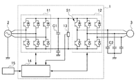
図1は、本発明の実施形態に係るモータ駆動装置1の回路構成を示す図である。
モータ駆動装置1は、商用の三相交流電源2及びモータ3と接続され、交流電源2からの電力を用いてモータ3を駆動及び制御する。
なお、交流電源2は、三相交流に限定されず、例えば、単相交流であってもよい。
順変換器11は、例えば、パワー半導体素子及びパワー半導体素子に逆並列に接続されたダイオードのブリッジ回路を有するダイオード整流コンバータ又はPWMコンバータで構成される。順変換器11は、モータ3へ電力を供給するときには、ダイオードによって三相交流電源からの交流電圧を全波整流して直流電圧に変換する。
また、モータ制御部14は、例えば、コンピュータ等を備える外部機器15と接続される。
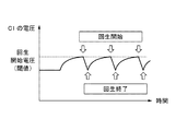
図2及び3は、本発明の実施形態に係るモータ駆動装置1の回生動作時の電流の流れを示す図である。図4は、DCリンクコンデンサC1の電圧変動を示す図である。
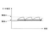
図5は、本発明の実施形態に係るモータ駆動装置1のDCリンクコンデンサC1の電圧変動を示す図である。
また、モータ制御部14は、電圧検出部13で検出される直流電圧値の単位時間当たりの増加量が一定量以上である場合には、回生を開始する電圧の閾値を第1の閾値Aよりも大きい第2の閾値Bに設定する。
なお、モータ制御部14は、回生を開始する電圧の閾値を第1の閾値A又は第2の閾値Bに設定した状態で処理を開始する。
ステップS4において、モータ制御部14は、第1の閾値Aで回生を開始し、その後、処理は、ステップ1へ戻る。
ステップS7において、モータ制御部14は、第2の閾値Bで回生を開始し、その後、処理は、ステップS1へ戻る。
2 交流電源
3 モータ
11 順変換器
12 逆変換器
13 電圧検出部
14 モータ制御部
15 外部機器
C1 DCリンクコンデンサ
C2 浮遊容量
Claims (4)
- 電源からの交流電力を直流電力に変換する順変換器と、
前記順変換器に接続されるDCリンクコンデンサと、
前記DCリンクコンデンサにおける直流電圧値を検出する電圧検出部と、
前記DCリンクコンデンサに接続され、前記直流電力をモータの駆動電力に変換すると共に、前記電圧検出部で検出される前記直流電圧値が前記モータの回生を開始する閾値に達した場合に、前記直流電力を三相交流電力に変換する逆変換器と、
前記直流電圧値の単位時間当たりの増加量が一定量未満である場合には、前記閾値を第1の閾値に設定し、前記直流電圧値の単位時間当たりの増加量が一定量以上である場合には、前記閾値を前記第1の閾値よりも大きい第2の閾値に設定するモータ制御部と、
を備えるモータ駆動装置。 - 前記モータ制御部は、前記直流電圧値の単位時間当たりの増加量が前記モータの減速時の直流電圧値の単位時間当たりの増加量よりも小さい場合に、前記直流電圧値の単位時間当たりの増加量が一定量未満であると判断し、前記閾値を第1の閾値に設定する請求項1に記載のモータ駆動装置。
- 前記モータ制御部は、前記閾値が前記第1の閾値に設定されている状態で、前記直流電圧値の単位時間当たりの増加量が前記モータ駆動装置の最大許容値を超える場合に、前記直流電圧値の単位時間当たりの増加量が一定量以上であると判断し、前記閾値を前記第2の閾値に設定する請求項1又は2に記載のモータ駆動装置。
- 前記第1の閾値、前記第2の閾値及び前記モータ駆動装置の最大許容値は、外部機器によって書き換え可能である請求項1から3のいずれか一項に記載のモータ駆動装置。
Priority Applications (4)
| Application Number | Priority Date | Filing Date | Title |
|---|---|---|---|
| JP2016080871A JP6608761B2 (ja) | 2016-04-14 | 2016-04-14 | Dcリンクコンデンサの電圧変動を抑制するモータ駆動装置 |
| US15/479,469 US10727775B2 (en) | 2016-04-14 | 2017-04-05 | Motor drive device suppressing voltage fluctuation in DC link capacitor |
| DE102017205874.9A DE102017205874A1 (de) | 2016-04-14 | 2017-04-06 | Motoransteuereinrichtung zur Unterdrückung von Spannungsschwankungen in einem DC-Stützkondensator |
| CN201710236288.6A CN107302332B (zh) | 2016-04-14 | 2017-04-12 | 抑制dc链路电容器的电压变动的电动机驱动装置 |
Applications Claiming Priority (1)
| Application Number | Priority Date | Filing Date | Title |
|---|---|---|---|
| JP2016080871A JP6608761B2 (ja) | 2016-04-14 | 2016-04-14 | Dcリンクコンデンサの電圧変動を抑制するモータ駆動装置 |
Publications (2)
| Publication Number | Publication Date |
|---|---|
| JP2017192225A true JP2017192225A (ja) | 2017-10-19 |
| JP6608761B2 JP6608761B2 (ja) | 2019-11-20 |
Family
ID=59980446
Family Applications (1)
| Application Number | Title | Priority Date | Filing Date |
|---|---|---|---|
| JP2016080871A Active JP6608761B2 (ja) | 2016-04-14 | 2016-04-14 | Dcリンクコンデンサの電圧変動を抑制するモータ駆動装置 |
Country Status (4)
| Country | Link |
|---|---|
| US (1) | US10727775B2 (ja) |
| JP (1) | JP6608761B2 (ja) |
| CN (1) | CN107302332B (ja) |
| DE (1) | DE102017205874A1 (ja) |
Cited By (1)
| Publication number | Priority date | Publication date | Assignee | Title |
|---|---|---|---|---|
| JP2020150713A (ja) * | 2019-03-14 | 2020-09-17 | 富士電機株式会社 | モータ駆動装置 |
Families Citing this family (2)
| Publication number | Priority date | Publication date | Assignee | Title |
|---|---|---|---|---|
| JP7299723B2 (ja) * | 2019-03-14 | 2023-06-28 | 三菱重工サーマルシステムズ株式会社 | 制御装置、電動コンプレッサおよび制御方法 |
| DE102022125719A1 (de) | 2022-10-05 | 2024-04-11 | Sma Solar Technology Ag | Verfahren zum betrieb eines leistungswandlers, steuereinheit und elektrolyseanlage |
Citations (2)
| Publication number | Priority date | Publication date | Assignee | Title |
|---|---|---|---|---|
| JP2014176252A (ja) * | 2013-03-12 | 2014-09-22 | Aisin Seiki Co Ltd | 空気調和装置 |
| WO2015050068A1 (ja) * | 2013-10-01 | 2015-04-09 | 日立オートモティブシステムズ株式会社 | 電力変換装置 |
Family Cites Families (9)
| Publication number | Priority date | Publication date | Assignee | Title |
|---|---|---|---|---|
| JP2007325377A (ja) | 2006-05-31 | 2007-12-13 | Nippon Reliance Kk | 電力変換装置 |
| WO2009128216A1 (ja) * | 2008-04-15 | 2009-10-22 | パナソニック株式会社 | モータ装置、およびそれらを備えたモータ駆動システム並びに集積回路装置 |
| US8473110B2 (en) * | 2008-11-25 | 2013-06-25 | Regal Beloit America, Inc. | Systems and methods for controlling operation of a motor |
| JP5444304B2 (ja) | 2011-10-25 | 2014-03-19 | ファナック株式会社 | 無効電流指令作成部を有するモータ駆動装置 |
| JP6070591B2 (ja) * | 2014-01-28 | 2017-02-01 | トヨタ自動車株式会社 | ハイブリッド車両およびハイブリッド車両の制御方法 |
| JP5826440B1 (ja) * | 2014-06-19 | 2015-12-02 | 三菱電機株式会社 | 交流モータ駆動システム |
| JP5797313B1 (ja) * | 2014-08-25 | 2015-10-21 | 株式会社京三製作所 | 回生サーキュレータ、高周波電源装置、及び高周波電力の回生方法 |
| JP6546203B2 (ja) * | 2015-02-10 | 2019-07-17 | 株式会社東芝 | 電力変換装置の制御装置、制御プログラム及び電力変換装置 |
| US10439402B2 (en) * | 2017-02-14 | 2019-10-08 | The Johns Hopkins University | Constant power adaptive power system |
-
2016
- 2016-04-14 JP JP2016080871A patent/JP6608761B2/ja active Active
-
2017
- 2017-04-05 US US15/479,469 patent/US10727775B2/en active Active
- 2017-04-06 DE DE102017205874.9A patent/DE102017205874A1/de active Pending
- 2017-04-12 CN CN201710236288.6A patent/CN107302332B/zh active Active
Patent Citations (2)
| Publication number | Priority date | Publication date | Assignee | Title |
|---|---|---|---|---|
| JP2014176252A (ja) * | 2013-03-12 | 2014-09-22 | Aisin Seiki Co Ltd | 空気調和装置 |
| WO2015050068A1 (ja) * | 2013-10-01 | 2015-04-09 | 日立オートモティブシステムズ株式会社 | 電力変換装置 |
Cited By (2)
| Publication number | Priority date | Publication date | Assignee | Title |
|---|---|---|---|---|
| JP2020150713A (ja) * | 2019-03-14 | 2020-09-17 | 富士電機株式会社 | モータ駆動装置 |
| JP7207040B2 (ja) | 2019-03-14 | 2023-01-18 | 富士電機株式会社 | モータ駆動装置 |
Also Published As
| Publication number | Publication date |
|---|---|
| JP6608761B2 (ja) | 2019-11-20 |
| CN107302332A (zh) | 2017-10-27 |
| CN107302332B (zh) | 2022-06-24 |
| US10727775B2 (en) | 2020-07-28 |
| DE102017205874A1 (de) | 2017-10-19 |
| US20170302213A1 (en) | 2017-10-19 |
Similar Documents
| Publication | Publication Date | Title |
|---|---|---|
| JP5931148B2 (ja) | 静電容量計算部を有するpwm整流器 | |
| JP6200457B2 (ja) | 初期充電回路の異常発熱を検出する手段を有するモータ駆動装置 | |
| JP6219888B2 (ja) | Pwmコンバータを有するモータ駆動装置 | |
| JP5077348B2 (ja) | モータ駆動装置、モータ装置、および集積回路装置 | |
| JP5954313B2 (ja) | モータ制御システム、制御装置及び制御方法 | |
| JP2009207305A (ja) | モータ駆動装置 | |
| JP6608761B2 (ja) | Dcリンクコンデンサの電圧変動を抑制するモータ駆動装置 | |
| JP5807156B2 (ja) | モータ駆動用インバータ制御回路および電気掃除機 | |
| JP5476788B2 (ja) | インバータ装置 | |
| JP6197690B2 (ja) | モータ制御システム | |
| JP2020058184A (ja) | 電力供給モード切替え機能を有するモータ駆動装置 | |
| JP4607717B2 (ja) | 交流電気車用電力変換装置 | |
| JP5214995B2 (ja) | 車両用電力変換装置及び車両用駆動制御装置 | |
| JP5248880B2 (ja) | 車両用電力変換装置及び車両用駆動制御装置 | |
| JP6957383B2 (ja) | 電力変換装置 | |
| JP5537264B2 (ja) | 電気推進船の駆動装置及び駆動方法 | |
| JP2014014226A (ja) | 交流電動機駆動装置 | |
| JP6704518B2 (ja) | エレベータの制御装置 | |
| JP6808471B2 (ja) | 初期充電装置及び負荷駆動システム | |
| JP5900136B2 (ja) | エレベータ駆動用電源装置 | |
| JP6800278B2 (ja) | 回転電機の制御装置 | |
| JP6927900B2 (ja) | Dcリンク部のコンデンサの短絡判定部を有するモータ駆動装置 | |
| JP2009171745A (ja) | 電動機駆動システム | |
| JP6616199B2 (ja) | モータの減速用速度変化率を変更する手段を有するモータ制御装置 | |
| JP4865892B2 (ja) | 交流電気車用電力変換装置及びその制御方法 |
Legal Events
| Date | Code | Title | Description |
|---|---|---|---|
| A621 | Written request for application examination |
Free format text: JAPANESE INTERMEDIATE CODE: A621 Effective date: 20170519 |
|
| A131 | Notification of reasons for refusal |
Free format text: JAPANESE INTERMEDIATE CODE: A131 Effective date: 20180130 |
|
| A521 | Request for written amendment filed |
Free format text: JAPANESE INTERMEDIATE CODE: A523 Effective date: 20180313 |
|
| A02 | Decision of refusal |
Free format text: JAPANESE INTERMEDIATE CODE: A02 Effective date: 20180605 |
|
| A521 | Request for written amendment filed |
Free format text: JAPANESE INTERMEDIATE CODE: A523 Effective date: 20180830 |
|
| A911 | Transfer to examiner for re-examination before appeal (zenchi) |
Free format text: JAPANESE INTERMEDIATE CODE: A911 Effective date: 20180907 |
|
| A912 | Re-examination (zenchi) completed and case transferred to appeal board |
Free format text: JAPANESE INTERMEDIATE CODE: A912 Effective date: 20181005 |
|
| A61 | First payment of annual fees (during grant procedure) |
Free format text: JAPANESE INTERMEDIATE CODE: A61 Effective date: 20191024 |
|
| R150 | Certificate of patent or registration of utility model |
Ref document number: 6608761 Country of ref document: JP Free format text: JAPANESE INTERMEDIATE CODE: R150 |