US10727775B2 - Motor drive device suppressing voltage fluctuation in DC link capacitor - Google Patents
Motor drive device suppressing voltage fluctuation in DC link capacitor Download PDFInfo
- Publication number
- US10727775B2 US10727775B2 US15/479,469 US201715479469A US10727775B2 US 10727775 B2 US10727775 B2 US 10727775B2 US 201715479469 A US201715479469 A US 201715479469A US 10727775 B2 US10727775 B2 US 10727775B2
- Authority
- US
- United States
- Prior art keywords
- threshold
- voltage
- voltage value
- motor
- drive device
- Prior art date
- Legal status (The legal status is an assumption and is not a legal conclusion. Google has not performed a legal analysis and makes no representation as to the accuracy of the status listed.)
- Active
Links
- 239000003990 capacitor Substances 0.000 title claims abstract description 52
- 230000008929 regeneration Effects 0.000 claims abstract description 29
- 238000011069 regeneration method Methods 0.000 claims abstract description 29
- 238000001514 detection method Methods 0.000 abstract description 17
- 238000005549 size reduction Methods 0.000 abstract description 6
- 239000004065 semiconductor Substances 0.000 description 8
- 230000000694 effects Effects 0.000 description 3
- 238000004519 manufacturing process Methods 0.000 description 3
- 238000001816 cooling Methods 0.000 description 2
- 238000005516 engineering process Methods 0.000 description 2
- 230000037361 pathway Effects 0.000 description 2
- 230000000630 rising effect Effects 0.000 description 2
- 230000008901 benefit Effects 0.000 description 1
- 230000008859 change Effects 0.000 description 1
- 230000008030 elimination Effects 0.000 description 1
- 238000003379 elimination reaction Methods 0.000 description 1
- 230000005284 excitation Effects 0.000 description 1
- 230000004044 response Effects 0.000 description 1
Images


Classifications
-
- H—ELECTRICITY
- H02—GENERATION; CONVERSION OR DISTRIBUTION OF ELECTRIC POWER
- H02P—CONTROL OR REGULATION OF ELECTRIC MOTORS, ELECTRIC GENERATORS OR DYNAMO-ELECTRIC CONVERTERS; CONTROLLING TRANSFORMERS, REACTORS OR CHOKE COILS
- H02P27/00—Arrangements or methods for the control of AC motors characterised by the kind of supply voltage
- H02P27/04—Arrangements or methods for the control of AC motors characterised by the kind of supply voltage using variable-frequency supply voltage, e.g. inverter or converter supply voltage
- H02P27/06—Arrangements or methods for the control of AC motors characterised by the kind of supply voltage using variable-frequency supply voltage, e.g. inverter or converter supply voltage using dc to ac converters or inverters
- H02P27/08—Arrangements or methods for the control of AC motors characterised by the kind of supply voltage using variable-frequency supply voltage, e.g. inverter or converter supply voltage using dc to ac converters or inverters with pulse width modulation
-
- H—ELECTRICITY
- H02—GENERATION; CONVERSION OR DISTRIBUTION OF ELECTRIC POWER
- H02M—APPARATUS FOR CONVERSION BETWEEN AC AND AC, BETWEEN AC AND DC, OR BETWEEN DC AND DC, AND FOR USE WITH MAINS OR SIMILAR POWER SUPPLY SYSTEMS; CONVERSION OF DC OR AC INPUT POWER INTO SURGE OUTPUT POWER; CONTROL OR REGULATION THEREOF
- H02M1/00—Details of apparatus for conversion
- H02M1/14—Arrangements for reducing ripples from dc input or output
-
- H—ELECTRICITY
- H02—GENERATION; CONVERSION OR DISTRIBUTION OF ELECTRIC POWER
- H02M—APPARATUS FOR CONVERSION BETWEEN AC AND AC, BETWEEN AC AND DC, OR BETWEEN DC AND DC, AND FOR USE WITH MAINS OR SIMILAR POWER SUPPLY SYSTEMS; CONVERSION OF DC OR AC INPUT POWER INTO SURGE OUTPUT POWER; CONTROL OR REGULATION THEREOF
- H02M5/00—Conversion of ac power input into ac power output, e.g. for change of voltage, for change of frequency, for change of number of phases
- H02M5/40—Conversion of ac power input into ac power output, e.g. for change of voltage, for change of frequency, for change of number of phases with intermediate conversion into dc
- H02M5/42—Conversion of ac power input into ac power output, e.g. for change of voltage, for change of frequency, for change of number of phases with intermediate conversion into dc by static converters
- H02M5/44—Conversion of ac power input into ac power output, e.g. for change of voltage, for change of frequency, for change of number of phases with intermediate conversion into dc by static converters using discharge tubes or semiconductor devices to convert the intermediate dc into ac
- H02M5/453—Conversion of ac power input into ac power output, e.g. for change of voltage, for change of frequency, for change of number of phases with intermediate conversion into dc by static converters using discharge tubes or semiconductor devices to convert the intermediate dc into ac using devices of a triode or transistor type requiring continuous application of a control signal
- H02M5/458—Conversion of ac power input into ac power output, e.g. for change of voltage, for change of frequency, for change of number of phases with intermediate conversion into dc by static converters using discharge tubes or semiconductor devices to convert the intermediate dc into ac using devices of a triode or transistor type requiring continuous application of a control signal using semiconductor devices only
- H02M5/4585—Conversion of ac power input into ac power output, e.g. for change of voltage, for change of frequency, for change of number of phases with intermediate conversion into dc by static converters using discharge tubes or semiconductor devices to convert the intermediate dc into ac using devices of a triode or transistor type requiring continuous application of a control signal using semiconductor devices only having a rectifier with controlled elements
-
- H—ELECTRICITY
- H02—GENERATION; CONVERSION OR DISTRIBUTION OF ELECTRIC POWER
- H02P—CONTROL OR REGULATION OF ELECTRIC MOTORS, ELECTRIC GENERATORS OR DYNAMO-ELECTRIC CONVERTERS; CONTROLLING TRANSFORMERS, REACTORS OR CHOKE COILS
- H02P6/00—Arrangements for controlling synchronous motors or other dynamo-electric motors using electronic commutation dependent on the rotor position; Electronic commutators therefor
- H02P6/14—Electronic commutators
Definitions
- the present invention relates to a motor drive device that suppresses voltage fluctuation in a DC link capacitor.
- the motor drive device that controls a motor such as a servomotor includes a DC link capacitor between a converter and an inverter.
- a motor drive device technology has been known for suppressing voltage fluctuation of the DC link capacitor (for example, refer to Patent Documents 1 and 2).
- the motor drive device described in Patent Document 1 includes voltage to ground capacitors C 100 at an input portion of the converter of a motor drive device 100 , as shown in FIG. 7 , for suppressing voltage fluctuation of the DC link capacitor.
- the technology for suppressing voltage fluctuation of the DC link capacitor by connecting a DC/DC power source, resistor 110 , etc. to both ends of the DC link capacitor has also been known, as shown in FIG. 7 .
- the motor drive device described in Patent Document 2 in the case of the voltage of the DC link capacitor rising, increases the consumption energy of the motor by flowing reactive current to the motor to suppress voltage fluctuation of the DC link capacitor.
- Patent Document 1 Japanese Unexamined Patent Application, Publication No. 2007-325377
- Patent Document 2 Japanese Unexamined Patent Application, Publication No. 2013-093957
- the present invention has an object of providing a motor drive device that suppresses voltage fluctuation in the DC link capacitor, as well as enabling for low cost and a size reduction.
- a motor control device includes: a converter (for example, the converter 11 described later) that converts AC electric power from a power source into DC electric power; a voltage detection unit (for example, the voltage detection unit 13 described later) that detects a DC voltage value of the DC link capacitor (for example, the DC link capacitor C 1 described later); an inverter (for example, the inverter 12 described later) that is connected to the DC link capacitor, converts the DC electric power into drive electric power of a motor (for example, the motor 3 described later), and converts the DC electric power into three-phase AC electric power in a case of the DC voltage value detected by the voltage detection unit reaching a threshold at which to start regeneration of the motor; and a motor control unit (for example, the motor control unit 14 described later) that sets the threshold to a first threshold in a case of an increased amount per unit time of the DC voltage value being less than a certain amount, and sets the threshold to a second threshold that is larger than the first threshold, in
- the motor control unit may determine that the increased amount per unit time of the DC voltage value is less than the certain amount, in a case of the increased amount per unit time of the DC voltage value being smaller than an increased amount per unit time of DC voltage value during deceleration of the motor, and set the threshold to a first threshold.
- the motor control unit in a state in which the threshold is set to the first threshold, may determine that the increased amount per unit time of the DC voltage value is at least the certain amount, in a case of the increased amount per unit time of the DC voltage value exceeding a maximum allowed value of the motor drive device, and set the threshold to a second threshold.
- the first threshold, the second threshold and the maximum allowed value of the motor drive device may be rewritable by external equipment.
- FIG. 1 is a view showing a circuit configuration of a motor drive device according to an embodiment of the present invention
- FIG. 2 is a view showing the flow of current during regeneration operation of the motor drive device according to the embodiment of the present invention
- FIG. 3 is a view showing the flow of current during regeneration operation of the motor drive device according to the embodiment of the present invention.
- FIG. 4 is a graph showing voltage fluctuation of a DC link capacitor
- FIG. 5 is a graph showing voltage fluctuation of the DC link capacitor of the motor drive device according to the embodiment of the present invention.
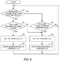
- FIG. 6 is a flowchart showing the flow of processing of the motor drive device according to the embodiment of the present invention.
- FIG. 7 is a view showing the circuit configuration of a conventional motor drive device.
- FIG. 1 is a view showing a circuit configuration of a motor drive device 1 according to the embodiment of the present invention.
- the motor drive device 1 is connected with a commercial three-phase AC power source 2 and motor 3 , and drives and controls the motor 3 using the electric power from the AC power source 2 .
- the AC power source 2 is not limited to three-phase alternating current, and may be single-phase alternating current, for example.
- the motor drive device 1 includes a converter 11 , inverter 12 , DC link capacitor C 1 , voltage detection unit 13 , and motor control unit 14 .
- the converter 11 converts the AC electric power inputted from the AC power source 2 into DC electric power.
- the converter 11 for example, is configured by a diode rectification converter or PWM converter having a power semiconductor element and a bridge circuit of a diode connected reversely parallel to the power semiconductor element.
- the converter 11 full-wave rectifies the AC electric power from the three-phase AC power source to convert to DC electric power by way of the diode, when supplying electric power to the motor 3 .
- the inverter 12 converts the DC electric power into AC electric power for driving of the motor 3 . In addition, the inverter 12 converts the AC electric power regenerated from the motor 3 into DC electric power.
- the inverter 12 for example, is configured from power semiconductor elements and a bridge circuit connected reversely parallel thereto. Then, by ON-OFF controlling (e.g., PWM control) these power semiconductor elements according to the commands from the motor control unit 14 , the DC electric power is converted into AC electric power of a desired waveform and frequency. The inverter 12 supplies the outputted AC current to the motor 3 .
- ON-OFF controlling e.g., PWM control
- the switching operation of the inverter 12 is controlled by the motor control unit 14 .
- the motor control unit 14 creates a command for the motor 3 to operate at a desired speed (accelerate, decelerate, constant speed, stop, etc.), torque or rotor position.
- the motor control unit 14 outputs ON-OFF commands to the power semiconductor elements of the inverter 12 , so that the inverter 12 outputs AC current having the waveform and frequency required in order for the motor 3 to operate.
- the AC current outputted by the inverter 12 is inputted to the motor 3 , whereby the motor 3 performs a rotation operation.
- the DC link capacitor C 1 connects the DC side of the converter 11 with the DC side of the inverter 12 , and performs transfer of DC electric power.
- the DC link capacitor C 1 smooths the DC voltage converted by the converter 11 or inverter 12 .
- the voltage detection unit 13 detects the DC voltage value of the DC link capacitor C 1 .
- the voltage detection unit 13 sends the detected DC voltage value to the motor control unit 14 .
- As the voltage detection unit 13 it is possible to use an existing voltage detection circuit, for example.
- the motor control unit 14 is connected with the converter 11 , the inverter 12 and the voltage detection unit 13 , and performs predetermined controls.
- the motor control unit 14 is configured by an arithmetic processor such as a DSP (Digital Signal Processor), or FPGA (field-Programmable Gate Array), for example. Operation of the motor control unit 14 is realized by executing predetermined software (program).
- the motor control unit 14 is connected, for example, with external equipment 15 including a computer, etc.
- FIGS. 2 and 3 are views showing the flow of current during regeneration operation of the motor drive device 1 according to the embodiment of the present invention.
- FIG. 4 is a view showing voltage fluctuation of the DC link capacitor C 1 .
- the voltage of the DC link capacitor C 1 increases according to ON/OFF of the power semiconductor element S 1 . Then, when reaching the voltage (threshold) at which the voltage of the DC link capacitor C 1 starts regeneration as shown in FIG. 4 , regeneration is started.
- the voltage increase of the DC link capacitor C 1 is not a voltage increase by the regeneration electric power generating during deceleration of the motor 3 ; therefore, the voltage increase of the DC link capacitor C 1 is instantly eliminated and regeneration also ends.
- FIG. 5 is a graph showing the voltage fluctuation of the DC link capacitor C 1 of the motor drive device 1 according to the embodiment of the present invention.
- the motor control device 14 sets the threshold for the voltage to start regeneration to a first threshold A, in a case of the increased amount per unit time of the DC voltage value detected by the voltage detection unit 13 being less than a certain amount.
- the motor control unit 14 sets the threshold for the voltage at which to start regeneration to a second threshold B which is larger than the first threshold A, in the case of the increased amount per unit time of the DC voltage value detected by the voltage detection unit 13 being at least a certain amount.
- the motor control unit 14 curbs a drastic rising in the voltage of the DC link capacitor C 1 , by performing regeneration also in the case of the increased amount per unit time of the voltage of the DC link capacitor C 1 being small (first threshold A) in this way.
- the motor drive device 1 can thereby curb the voltage fluctuation of the DC link capacitor C 1 occurring by repetition of charge-discharge of the charge of the floating capacitance C 2 and the start/end of regeneration.
- the motor control unit 14 determines that the increased amount per unit time of the DC voltage value is less than a certain amount in a case of the increased amount per unit time of the DC voltage value being smaller than the increased amount per unit time of the DC voltage amount during deceleration of the motor 3 , and sets the threshold for the voltage at which to start regeneration to the first threshold A.
- the motor control unit 14 may determine whether or not the increased amount per unit time of the DC voltage value is less than a certain amount, by obtaining the slope of voltage fluctuation of the DC link capacitor C 1 .
- the motor control unit 14 determines that the increase amount per unit time of the DC voltage value is at least a certain amount, in a case of the increased amount per unit time of the DC voltage value exceeding a maximum allowed value of the motor drive device 1 , and sets the threshold to the second threshold B.
- the first threshold A, second threshold B and maximum allowed value of the motor drive device 1 are preferably rewritable by the external equipment 15 connected to the motor control unit 14 .
- FIG. 6 is flowchart showing the flow of processing of the motor drive device 1 according to the embodiment of the present invention. It should be noted that the motor control unit 14 starts the processing in a state setting the threshold for the voltage at which to start regeneration to the first threshold A or the second threshold B.
- Step S 1 the motor control unit 14 determines whether or not the increased amount per unit time of the DC voltage value detected by the voltage detection amount 13 is less than the certain amount, by determining whether or not the increased amount per unit time of the DC voltage value is smaller than the increased amount per unit time of the DC voltage value during deceleration of the motor 3 .
- the processing advances to Step S 2 .
- the processing advances to Step S 5 .
- Step S 2 the motor control unit 14 determines whether or not the increased amount per unit time of the DC voltage value is less than the maximum allowed value for the motor drive device 1 . In the case of the increased amount per unit time of the DC voltage value being less than the maximum allowed value for the motor drive device 1 (YES), the processing advances to Step S 3 . In the case of the increase amount per unit time of the DC voltage value exceeding the maximum allowed value of the motor drive device 1 (NO), the processing advances to Step S 6 .
- Step S 3 the motor control unit 14 sets the threshold for the voltage at which to start regeneration to the first threshold A.
- Step S 4 the motor control unit 14 starts regeneration at the first threshold A, and subsequently, the processing returns to Step S 1 .
- Step S 5 the motor control unit 14 determines whether the voltage value of the DC link capacitor C 1 , i.e. DC voltage value detected by the voltage detection unit 13 , has reached the second threshold B. In the case of the DC voltage value having reached the second threshold B (YES), the processing advances to Step S 6 . In the case of the DC voltage value not having reached the second threshold B (NO), the processing returns to Step S 1 .
- Step S 6 the motor control unit 14 sets the threshold for the voltage at which to start regeneration to the second threshold B.
- Step S 7 the motor control unit 14 starts regeneration at the second threshold B, and subsequently, the processing returns to Step S 1 .
- the motor drive device 1 sets the threshold for the voltage at which to start regeneration to the first threshold A or second threshold B, in response to the increased amount per unit time of the DC voltage value detected by the voltage detection unit 13 .
- the motor drive device 1 can thereby curb the voltage fluctuation of the DC link capacitor C 1 produced by charge-discharge of the charge of the floating capacitance C 2 and start/end of regeneration.
- the motor drive device 1 curbs the voltage fluctuation of the DC link capacitor C 1 according to the setting of the threshold; therefore, for example, it is not necessary to provide a device or the like for cooling the motor accompanying the increase in thermal loss of the motor. Therefore, the motor drive device 1 curbs the voltage fluctuation of the DC link capacitor C 1 , and enables a decrease in production cost and a size reduction.
- the motor drive device 1 sets the threshold to the first threshold A in the case of the increased amount per unit time of the DC voltage value being smaller than the increased amount per unit time of the DC voltage value during deceleration of the motor 3 . In this way, the motor drive device 1 can appropriately set the threshold according to the state of the motor 3 , by judging the increased amount per unit time of the DC voltage value with the increase amount per unit time of the DC voltage value during deceleration of the motor 3 .
- the motor drive device 1 sets the threshold to the second threshold B which is greater than the first threshold A, in a case of the increased amount per unit time of the DC voltage value exceeding a maximum allowed value of the motor drive device 1 .
- the motor drive device 1 can thereby appropriately set the threshold according to the state of the DC link capacitor C 1 to perform the appropriate regeneration.
- the motor drive device 1 in the motor drive device 1 , the first threshold A, second threshold B and maximum allowed value of the motor drive device 1 are rewritable by external equipment 15 connected to the motor control unit 14 ; therefore, the motor drive device 1 can change the first threshold, second threshold and maximum allowed value to appropriate values, even if after setting values temporarily.
- the motor control unit 14 may determine a state of all of the motors 3 stopping as the motor 3 being stopped, for example.
- the motor control unit 14 may determine from the rotation command or speed command to the motor 3 as the state in which the motor 3 stopped, or may determine according to an event of the current of the motor 3 becoming 0.
Applications Claiming Priority (2)
| Application Number | Priority Date | Filing Date | Title |
|---|---|---|---|
| JP2016-080871 | 2016-04-14 | ||
| JP2016080871A JP6608761B2 (ja) | 2016-04-14 | 2016-04-14 | Dcリンクコンデンサの電圧変動を抑制するモータ駆動装置 |
Publications (2)
| Publication Number | Publication Date |
|---|---|
| US20170302213A1 US20170302213A1 (en) | 2017-10-19 |
| US10727775B2 true US10727775B2 (en) | 2020-07-28 |
Family
ID=59980446
Family Applications (1)
| Application Number | Title | Priority Date | Filing Date |
|---|---|---|---|
| US15/479,469 Active US10727775B2 (en) | 2016-04-14 | 2017-04-05 | Motor drive device suppressing voltage fluctuation in DC link capacitor |
Country Status (4)
| Country | Link |
|---|---|
| US (1) | US10727775B2 (ja) |
| JP (1) | JP6608761B2 (ja) |
| CN (1) | CN107302332B (ja) |
| DE (1) | DE102017205874A1 (ja) |
Families Citing this family (3)
| Publication number | Priority date | Publication date | Assignee | Title |
|---|---|---|---|---|
| JP7299723B2 (ja) * | 2019-03-14 | 2023-06-28 | 三菱重工サーマルシステムズ株式会社 | 制御装置、電動コンプレッサおよび制御方法 |
| JP7207040B2 (ja) * | 2019-03-14 | 2023-01-18 | 富士電機株式会社 | モータ駆動装置 |
| DE102022125719A1 (de) | 2022-10-05 | 2024-04-11 | Sma Solar Technology Ag | Verfahren zum betrieb eines leistungswandlers, steuereinheit und elektrolyseanlage |
Citations (11)
| Publication number | Priority date | Publication date | Assignee | Title |
|---|---|---|---|---|
| JP2007325377A (ja) | 2006-05-31 | 2007-12-13 | Nippon Reliance Kk | 電力変換装置 |
| US20100131083A1 (en) * | 2008-11-25 | 2010-05-27 | Thaylen Leany | Systems and methods for controlling operation of a motor |
| US20110029137A1 (en) * | 2008-04-15 | 2011-02-03 | Panasonic Corporation | Motor devices, and motor driving system and integrated circuit device comprising the same |
| US20130099705A1 (en) * | 2011-10-25 | 2013-04-25 | Fanuc Corporation | Motor driving device having reactive current instruction generating unit |
| JP2014176252A (ja) | 2013-03-12 | 2014-09-22 | Aisin Seiki Co Ltd | 空気調和装置 |
| WO2015050068A1 (ja) | 2013-10-01 | 2015-04-09 | 日立オートモティブシステムズ株式会社 | 電力変換装置 |
| WO2015194013A1 (ja) * | 2014-06-19 | 2015-12-23 | 三菱電機株式会社 | 交流モータ駆動システム |
| US20160368483A1 (en) * | 2014-01-28 | 2016-12-22 | Toyota Jidosha Kabushiki Kaisha | Hybrid vehicle and control method for hybrid vehicle |
| US20170279364A1 (en) * | 2014-08-25 | 2017-09-28 | Kyosan Electric Mfg. Co., Ltd. | Regeneration circulator, high-frequency power supply device, and high-frequency power regeneration method |
| US20180226803A1 (en) * | 2015-02-10 | 2018-08-09 | Kabushiki Kaisha Toshiba | Control device for power converter, control program and power conversion device |
| US10439402B2 (en) * | 2017-02-14 | 2019-10-08 | The Johns Hopkins University | Constant power adaptive power system |
-
2016
- 2016-04-14 JP JP2016080871A patent/JP6608761B2/ja active Active
-
2017
- 2017-04-05 US US15/479,469 patent/US10727775B2/en active Active
- 2017-04-06 DE DE102017205874.9A patent/DE102017205874A1/de active Pending
- 2017-04-12 CN CN201710236288.6A patent/CN107302332B/zh active Active
Patent Citations (13)
| Publication number | Priority date | Publication date | Assignee | Title |
|---|---|---|---|---|
| JP2007325377A (ja) | 2006-05-31 | 2007-12-13 | Nippon Reliance Kk | 電力変換装置 |
| US20110029137A1 (en) * | 2008-04-15 | 2011-02-03 | Panasonic Corporation | Motor devices, and motor driving system and integrated circuit device comprising the same |
| US20100131083A1 (en) * | 2008-11-25 | 2010-05-27 | Thaylen Leany | Systems and methods for controlling operation of a motor |
| US20130099705A1 (en) * | 2011-10-25 | 2013-04-25 | Fanuc Corporation | Motor driving device having reactive current instruction generating unit |
| JP2013093957A (ja) | 2011-10-25 | 2013-05-16 | Fanuc Ltd | 無効電流指令作成部を有するモータ駆動装置 |
| JP2014176252A (ja) | 2013-03-12 | 2014-09-22 | Aisin Seiki Co Ltd | 空気調和装置 |
| WO2015050068A1 (ja) | 2013-10-01 | 2015-04-09 | 日立オートモティブシステムズ株式会社 | 電力変換装置 |
| US20160368483A1 (en) * | 2014-01-28 | 2016-12-22 | Toyota Jidosha Kabushiki Kaisha | Hybrid vehicle and control method for hybrid vehicle |
| WO2015194013A1 (ja) * | 2014-06-19 | 2015-12-23 | 三菱電機株式会社 | 交流モータ駆動システム |
| US20170149369A1 (en) * | 2014-06-19 | 2017-05-25 | Mitsubishi Electric Corporation | Ac motor drive system |
| US20170279364A1 (en) * | 2014-08-25 | 2017-09-28 | Kyosan Electric Mfg. Co., Ltd. | Regeneration circulator, high-frequency power supply device, and high-frequency power regeneration method |
| US20180226803A1 (en) * | 2015-02-10 | 2018-08-09 | Kabushiki Kaisha Toshiba | Control device for power converter, control program and power conversion device |
| US10439402B2 (en) * | 2017-02-14 | 2019-10-08 | The Johns Hopkins University | Constant power adaptive power system |
Also Published As
| Publication number | Publication date |
|---|---|
| JP2017192225A (ja) | 2017-10-19 |
| CN107302332B (zh) | 2022-06-24 |
| US20170302213A1 (en) | 2017-10-19 |
| JP6608761B2 (ja) | 2019-11-20 |
| DE102017205874A1 (de) | 2017-10-19 |
| CN107302332A (zh) | 2017-10-27 |
Similar Documents
| Publication | Publication Date | Title |
|---|---|---|
| CN1024456C (zh) | 电梯的停电运行装置 | |
| US9954426B2 (en) | Motor driving device having PWM converter | |
| JP5381361B2 (ja) | インバータ装置 | |
| EP2273662B1 (en) | Power conversion device | |
| JP5602890B2 (ja) | 蓄電装置および抵抗放電装置を有するモータ制御装置 | |
| US10059563B2 (en) | Elevator car speed control in a battery powered elevator system | |
| EP1862348A1 (en) | Motor control apparatus and on-vehicle motor drive system | |
| JP2016005317A (ja) | 充電抵抗の保護手段を有するモータ制御装置 | |
| US20090218976A1 (en) | Motor driving apparatus | |
| US8736234B2 (en) | Power converter control apparatus | |
| EP2675060A1 (en) | Power conversion apparatus | |
| US10727775B2 (en) | Motor drive device suppressing voltage fluctuation in DC link capacitor | |
| EP3138725B1 (en) | Dual-source multi-mode vehicle power supply | |
| EP2034608A1 (en) | Inverter control method | |
| CN105141214B (zh) | 一种电机控制器对母线电压故障的处理方法 | |
| EP2921337A2 (en) | Apparatus for controlling motor in electric vehicle and method for preventing overheating of traction motor | |
| US10566923B2 (en) | Motor drive device including PWM converter controlled in boosting ratio | |
| JP5753770B2 (ja) | 電力変換装置 | |
| US9647597B2 (en) | Motor control apparatus and method for controlling motor | |
| JP6197690B2 (ja) | モータ制御システム | |
| JP2014036552A (ja) | 充電用回路及びその充電方法 | |
| JP2012239247A (ja) | モータ制御装置 | |
| JP6030468B2 (ja) | 電力変換装置 | |
| TWI523403B (zh) | Motor control device and motor control method | |
| CN111512541A (zh) | 电动机驱动装置 |
Legal Events
| Date | Code | Title | Description |
|---|---|---|---|
| AS | Assignment |
Owner name: FANUC CORPORATION, JAPAN Free format text: ASSIGNMENT OF ASSIGNORS INTEREST;ASSIGNORS:YOSHIDA, TOMOKAZU;INABA, KIICHI;HANYUU, SHIGEKI;REEL/FRAME:041859/0144 Effective date: 20170209 |
|
| STPP | Information on status: patent application and granting procedure in general |
Free format text: RESPONSE TO NON-FINAL OFFICE ACTION ENTERED AND FORWARDED TO EXAMINER |
|
| STPP | Information on status: patent application and granting procedure in general |
Free format text: FINAL REJECTION MAILED |
|
| STPP | Information on status: patent application and granting procedure in general |
Free format text: ADVISORY ACTION MAILED |
|
| STPP | Information on status: patent application and granting procedure in general |
Free format text: DOCKETED NEW CASE - READY FOR EXAMINATION |
|
| STPP | Information on status: patent application and granting procedure in general |
Free format text: NON FINAL ACTION MAILED |
|
| STPP | Information on status: patent application and granting procedure in general |
Free format text: RESPONSE TO NON-FINAL OFFICE ACTION ENTERED AND FORWARDED TO EXAMINER |
|
| STPP | Information on status: patent application and granting procedure in general |
Free format text: PUBLICATIONS -- ISSUE FEE PAYMENT VERIFIED |
|
| STCF | Information on status: patent grant |
Free format text: PATENTED CASE |
|
| MAFP | Maintenance fee payment |
Free format text: PAYMENT OF MAINTENANCE FEE, 4TH YEAR, LARGE ENTITY (ORIGINAL EVENT CODE: M1551); ENTITY STATUS OF PATENT OWNER: LARGE ENTITY Year of fee payment: 4 |