JP2017192225A - Motor drive device for suppressing voltage fluctuation of dc link capacitor - Google Patents
Motor drive device for suppressing voltage fluctuation of dc link capacitor Download PDFInfo
- Publication number
- JP2017192225A JP2017192225A JP2016080871A JP2016080871A JP2017192225A JP 2017192225 A JP2017192225 A JP 2017192225A JP 2016080871 A JP2016080871 A JP 2016080871A JP 2016080871 A JP2016080871 A JP 2016080871A JP 2017192225 A JP2017192225 A JP 2017192225A
- Authority
- JP
- Japan
- Prior art keywords
- voltage
- threshold value
- motor
- link capacitor
- value
- Prior art date
- Legal status (The legal status is an assumption and is not a legal conclusion. Google has not performed a legal analysis and makes no representation as to the accuracy of the status listed.)
- Granted
Links
Images


Classifications
-
- H—ELECTRICITY
- H02—GENERATION; CONVERSION OR DISTRIBUTION OF ELECTRIC POWER
- H02P—CONTROL OR REGULATION OF ELECTRIC MOTORS, ELECTRIC GENERATORS OR DYNAMO-ELECTRIC CONVERTERS; CONTROLLING TRANSFORMERS, REACTORS OR CHOKE COILS
- H02P27/00—Arrangements or methods for the control of AC motors characterised by the kind of supply voltage
- H02P27/04—Arrangements or methods for the control of AC motors characterised by the kind of supply voltage using variable-frequency supply voltage, e.g. inverter or converter supply voltage
- H02P27/06—Arrangements or methods for the control of AC motors characterised by the kind of supply voltage using variable-frequency supply voltage, e.g. inverter or converter supply voltage using dc to ac converters or inverters
- H02P27/08—Arrangements or methods for the control of AC motors characterised by the kind of supply voltage using variable-frequency supply voltage, e.g. inverter or converter supply voltage using dc to ac converters or inverters with pulse width modulation
-
- H—ELECTRICITY
- H02—GENERATION; CONVERSION OR DISTRIBUTION OF ELECTRIC POWER
- H02M—APPARATUS FOR CONVERSION BETWEEN AC AND AC, BETWEEN AC AND DC, OR BETWEEN DC AND DC, AND FOR USE WITH MAINS OR SIMILAR POWER SUPPLY SYSTEMS; CONVERSION OF DC OR AC INPUT POWER INTO SURGE OUTPUT POWER; CONTROL OR REGULATION THEREOF
- H02M1/00—Details of apparatus for conversion
- H02M1/14—Arrangements for reducing ripples from dc input or output
-
- H—ELECTRICITY
- H02—GENERATION; CONVERSION OR DISTRIBUTION OF ELECTRIC POWER
- H02M—APPARATUS FOR CONVERSION BETWEEN AC AND AC, BETWEEN AC AND DC, OR BETWEEN DC AND DC, AND FOR USE WITH MAINS OR SIMILAR POWER SUPPLY SYSTEMS; CONVERSION OF DC OR AC INPUT POWER INTO SURGE OUTPUT POWER; CONTROL OR REGULATION THEREOF
- H02M5/00—Conversion of ac power input into ac power output, e.g. for change of voltage, for change of frequency, for change of number of phases
- H02M5/40—Conversion of ac power input into ac power output, e.g. for change of voltage, for change of frequency, for change of number of phases with intermediate conversion into dc
- H02M5/42—Conversion of ac power input into ac power output, e.g. for change of voltage, for change of frequency, for change of number of phases with intermediate conversion into dc by static converters
- H02M5/44—Conversion of ac power input into ac power output, e.g. for change of voltage, for change of frequency, for change of number of phases with intermediate conversion into dc by static converters using discharge tubes or semiconductor devices to convert the intermediate dc into ac
- H02M5/453—Conversion of ac power input into ac power output, e.g. for change of voltage, for change of frequency, for change of number of phases with intermediate conversion into dc by static converters using discharge tubes or semiconductor devices to convert the intermediate dc into ac using devices of a triode or transistor type requiring continuous application of a control signal
- H02M5/458—Conversion of ac power input into ac power output, e.g. for change of voltage, for change of frequency, for change of number of phases with intermediate conversion into dc by static converters using discharge tubes or semiconductor devices to convert the intermediate dc into ac using devices of a triode or transistor type requiring continuous application of a control signal using semiconductor devices only
- H02M5/4585—Conversion of ac power input into ac power output, e.g. for change of voltage, for change of frequency, for change of number of phases with intermediate conversion into dc by static converters using discharge tubes or semiconductor devices to convert the intermediate dc into ac using devices of a triode or transistor type requiring continuous application of a control signal using semiconductor devices only having a rectifier with controlled elements
-
- H—ELECTRICITY
- H02—GENERATION; CONVERSION OR DISTRIBUTION OF ELECTRIC POWER
- H02P—CONTROL OR REGULATION OF ELECTRIC MOTORS, ELECTRIC GENERATORS OR DYNAMO-ELECTRIC CONVERTERS; CONTROLLING TRANSFORMERS, REACTORS OR CHOKE COILS
- H02P6/00—Arrangements for controlling synchronous motors or other dynamo-electric motors using electronic commutation dependent on the rotor position; Electronic commutators therefor
- H02P6/14—Electronic commutators
Abstract
Description
本発明は、DCリンクコンデンサの電圧変動を抑制するモータ駆動装置に関する。 The present invention relates to a motor drive device that suppresses voltage fluctuation of a DC link capacitor.
従来より、サーボモータ等のモータを制御するモータ駆動装置は、順変換器と逆変換器との間にDCリンクコンデンサを備えている。このようなモータ駆動装置において、DCリンクコンデンサの電圧変動を抑制する技術が知られている(例えば、特許文献1及び2参照)。
2. Description of the Related Art Conventionally, a motor drive device that controls a motor such as a servo motor has a DC link capacitor between a forward converter and an inverse converter. In such a motor drive device, a technique for suppressing voltage fluctuation of a DC link capacitor is known (see, for example,
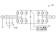
例えば、特許文献1に記載のモータ駆動装置は、DCリンクコンデンサの電圧変動を抑制するために、図7に示すようにモータ駆動装置100の順変換器の入力部分に対地間コンデンサC100を備えている。また、図7に示すようにDCリンクコンデンサの両端にDC/DC電源や抵抗110等を接続することによりDCリンクコンデンサの電圧変動を抑制する技術も知られている。
For example, the motor drive device described in
また、特許文献2に記載のモータ駆動装置は、DCリンクコンデンサの電圧が上昇した場合に、モータに無効電流を流すことによりモータの消費エネルギーを増加させ、DCリンクコンデンサの電圧変動を抑制している。 In addition, when the voltage of the DC link capacitor rises, the motor driving device described in Patent Document 2 increases the energy consumption of the motor by flowing an invalid current to the motor, and suppresses the voltage fluctuation of the DC link capacitor. Yes.
しかし、特許文献1等のように対地間コンデンサ、DC/DC電源、抵抗等の部品をモータ駆動装置に追加した場合、製造コストが増大し、モータ駆動装置の小型化が困難であった。
However, when components such as a ground-to-ground capacitor, a DC / DC power supply, and a resistor are added to the motor driving device as in
また、特許文献2のようにモータの消費エネルギーを増加させる場合、モータの熱損失が大きくなるため、モータの熱損失の増加に伴ってモータを冷却する装置を設ける必要がある。そのため、特許文献2のようなモータ駆動装置でも製造コストが増大し、モータ駆動装置の小型化が困難であった。 In addition, when the energy consumption of the motor is increased as in Patent Document 2, since the heat loss of the motor increases, it is necessary to provide a device for cooling the motor as the heat loss of the motor increases. For this reason, the manufacturing cost of the motor driving device as in Patent Document 2 also increases, and it is difficult to reduce the size of the motor driving device.
そこで、本発明は、DCリンクコンデンサの電圧変動を抑制すると共に、低コスト及び小型化が可能なモータ駆動装置を提供することを目的とする。 Therefore, an object of the present invention is to provide a motor drive device that can suppress voltage fluctuation of a DC link capacitor and can be reduced in cost and size.
本発明に係るモータ駆動装置(例えば、後述のモータ駆動装置1)は、電源からの交流電力を直流電力に変換する順変換器(例えば、後述の順変換器11)と、前記順変換器に接続されるDCリンクコンデンサ(例えば、後述のDCリンクコンデンサC1)と、前記DCリンクコンデンサにおける直流電圧値を検出する電圧検出部(例えば、後述の電圧検出部13)と、前記DCリンクコンデンサに接続され、前記直流電力をモータの駆動電力に変換すると共に、前記電圧検出部で検出される前記直流電圧値が前記モータの回生を開始する閾値に達した場合に、前記直流電力を三相交流電力に変換する逆変換器(例えば、後述の逆変換器12)と、前記直流電圧値の単位時間当たりの増加量が一定量未満である場合には、前記閾値を第1の閾値に設定し、前記直流電圧値の単位時間当たりの増加量が一定量以上である場合には、前記閾値を前記第1の閾値よりも大きい第2の閾値に設定するモータ制御部(例えば、後述のモータ制御部14)と、を備える
A motor drive device according to the present invention (for example, a
前記モータ制御部は、前記直流電圧値の単位時間当たりの増加量が前記モータの減速時の直流電圧値の単位時間当たりの増加量よりも小さい場合に、前記直流電圧値の単位時間当たりの増加量が一定量未満であると判断し、前記閾値を第1の閾値に設定してもよい。 The motor control unit increases the DC voltage value per unit time when the increase amount per unit time of the DC voltage value is smaller than the increase amount per unit time of the DC voltage value during deceleration of the motor. The amount may be determined to be less than a certain amount, and the threshold value may be set as the first threshold value.
前記モータ制御部は、前記閾値が前記第1の閾値に設定されている状態で、前記直流電圧値の単位時間当たりの増加量が前記モータ駆動装置の最大許容値を超える場合に、前記直流電圧値の単位時間当たりの増加量が一定量以上であると判断し、前記閾値を前記第2の閾値に設定してもよい。 In the state where the threshold value is set to the first threshold value, the motor control unit is configured to output the DC voltage when an increase amount per unit time of the DC voltage value exceeds a maximum allowable value of the motor driving device. The increase amount per unit time may be determined to be a certain amount or more, and the threshold value may be set as the second threshold value.
前記第1の閾値、前記第2の閾値及び前記モータ駆動装置の最大許容値は、外部機器によって書き換え可能であってもよい。 The first threshold value, the second threshold value, and the maximum allowable value of the motor driving device may be rewritable by an external device.
本発明によれば、DCリンクコンデンサの電圧変動を抑制すると共に、低コスト及び小型化が可能なモータ駆動装置を提供することができる。 ADVANTAGE OF THE INVENTION According to this invention, while suppressing the voltage fluctuation of a DC link capacitor, the motor drive device which can be reduced in cost and size can be provided.
以下、本発明の実施形態の一例について説明する。
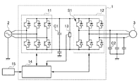
図1は、本発明の実施形態に係るモータ駆動装置1の回路構成を示す図である。
モータ駆動装置1は、商用の三相交流電源2及びモータ3と接続され、交流電源2からの電力を用いてモータ3を駆動及び制御する。
なお、交流電源2は、三相交流に限定されず、例えば、単相交流であってもよい。
Hereinafter, an example of an embodiment of the present invention will be described.
FIG. 1 is a diagram showing a circuit configuration of a
The
Note that the AC power supply 2 is not limited to a three-phase AC, and may be a single-phase AC, for example.
モータ駆動装置1は、順変換器(コンバータ)11と、逆変換器(インバータ)12と、DCリンクコンデンサC1と、電圧検出部13と、モータ制御部14と、を備える。
The
順変換器11は、交流電源2から入力された交流電力を直流電力に変換する。
順変換器11は、例えば、パワー半導体素子及びパワー半導体素子に逆並列に接続されたダイオードのブリッジ回路を有するダイオード整流コンバータ又はPWMコンバータで構成される。順変換器11は、モータ3へ電力を供給するときには、ダイオードによって三相交流電源からの交流電圧を全波整流して直流電圧に変換する。
The
The
逆変換器12は、直流電力をモータ3の駆動のための交流電力に変換する。また、逆変換器12は、モータ3から回生される交流電力を直流電力に変換する。
The
逆変換器12は、例えば、パワー半導体素子及びこれに逆並列に接続されたダイオードを有するブリッジ回路から構成される。そして、これらのパワー半導体素子をモータ制御部14からの指令によりオンオフ制御(例えばPWM制御)することにより、直流電圧を所望の波形及び周波数の交流電圧に変換する。逆変換器12は、出力した交流電流をモータ3に供給する。
The
逆変換器12のスイッチング動作は、モータ制御部14によって制御される。すなわち、モータ制御部14は、モータ3が所望の速度(加速、減速、定速、停止等)、トルク又は回転子の位置で動作するための指令を作成する。
The switching operation of the
そして、モータ制御部14は、当該指令に基づいてモータ3が動作するために必要な波形や周波数を有する交流電流を逆変換器12が出力するように、逆変換器12のパワー半導体素子にオンオフ指令を出力する。モータ3には逆変換器12が出力した交流電流が入力され、これによりモータ3は回転動作を行う。
Then, the
DCリンクコンデンサC1は、順変換器11の直流側と逆変換器12の直流側とを接続し、直流電力の受け渡しを行う。DCリンクコンデンサC1は、順変換器11又は逆変換器12によって変換された直流電圧を平滑化する。
The DC link capacitor C1 connects the direct current side of the
電圧検出部13は、DCリンクコンデンサC1における直流電圧値を検出する。電圧検出部13は、検出した直流電圧値をモータ制御部14に送信する。電圧検出部13としては、例えば、既存の電圧検出回路を用いることができる。
The
モータ制御部14は、順変換器11、逆変換器12及び電圧検出部13と接続され、所定の制御を行う。モータ制御部14は、例えば、DSP(Digital Signal Processor)、FPGA(Field−Programmable Gate Array)等の演算プロセッサで構成される。モータ制御部14の動作は、所定のソフトウェア(プログラム)を実行することで実現される。
また、モータ制御部14は、例えば、コンピュータ等を備える外部機器15と接続される。
The
In addition, the
次に、本発明の実施形態に係るモータ駆動装置1のDCリンクコンデンサC1の電圧変動について説明する。
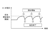
図2及び3は、本発明の実施形態に係るモータ駆動装置1の回生動作時の電流の流れを示す図である。図4は、DCリンクコンデンサC1の電圧変動を示す図である。
Next, voltage fluctuation of the DC link capacitor C1 of the
2 and 3 are diagrams showing a current flow during the regenerative operation of the
モータ3が停止して励磁のみの状態のときに、逆変換器12のパワー半導体素子S1をオンにすると、図2に示すように、充電電流は、交流電源2から浮遊容量C2に対してルートXの経路で流れ、浮遊容量C2に電荷が蓄えられる。
When the power semiconductor element S1 of the
次に、パワー半導体素子S1をオフにすると、図3に示すように、浮遊容量C2に蓄えられた電荷は、DCリンクコンデンサC1にルートYの経路で流れ込み、DCリンクコンデンサC1の電圧が増加する。 Next, when the power semiconductor element S1 is turned off, as shown in FIG. 3, the charge stored in the stray capacitance C2 flows into the DC link capacitor C1 through the route Y, and the voltage of the DC link capacitor C1 increases. .
パワー半導体素子S1のオン・オフによりDCリンクコンデンサC1の電圧は増加する。そして、図4に示すようにDCリンクコンデンサC1の電圧が回生を開始する電圧(閾値)に達すると、回生が開始される。しかし、DCリンクコンデンサC1の電圧増加は、モータ3の減速時に発生する回生電力による電圧増加ではないため、DCリンクコンデンサC1の電圧増加は、直ぐに解消され、回生も終了する。 The voltage of the DC link capacitor C1 increases as the power semiconductor element S1 is turned on / off. Then, as shown in FIG. 4, when the voltage of the DC link capacitor C1 reaches a voltage (threshold value) at which regeneration is started, regeneration is started. However, the increase in the voltage of the DC link capacitor C1 is not an increase in the voltage due to the regenerative power generated when the motor 3 is decelerated. Therefore, the increase in the voltage of the DC link capacitor C1 is immediately eliminated and the regeneration is also terminated.
このように、浮遊容量C2の電荷の充放電及び回生の開始/終了の繰り返しによって、DCリンクコンデンサC1の電圧増加と電圧増加の解消とが繰り返されるため、DCリンクコンデンサC1の電圧変動は、大きくなる。 As described above, since the charge increase / decrease of the charge of the stray capacitance C2 and the start / end of the regeneration are repeated, the voltage increase of the DC link capacitor C1 and the cancellation of the voltage increase are repeated. Become.
そこで、DCリンクコンデンサC1の電圧変動を抑制するために、本発明の実施形態に係るモータ駆動装置1は、以下のような制御を行う。
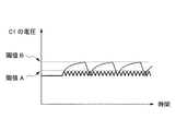
図5は、本発明の実施形態に係るモータ駆動装置1のDCリンクコンデンサC1の電圧変動を示す図である。
Therefore, in order to suppress the voltage fluctuation of the DC link capacitor C1, the
FIG. 5 is a diagram showing voltage fluctuation of the DC link capacitor C1 of the
図5に示すように、モータ制御部14は、電圧検出部13で検出される直流電圧値の単位時間当たりの増加量が一定量未満である場合には、回生を開始する電圧の閾値を第1の閾値Aに設定する。
また、モータ制御部14は、電圧検出部13で検出される直流電圧値の単位時間当たりの増加量が一定量以上である場合には、回生を開始する電圧の閾値を第1の閾値Aよりも大きい第2の閾値Bに設定する。
As shown in FIG. 5, when the increase amount per unit time of the DC voltage value detected by the
Further, the
このように、モータ制御部14は、DCリンクコンデンサC1の電圧の単位時間当たりの増加量が小さい場合(第1の閾値A)でも回生を行うことにより、DCリンクコンデンサC1の電圧の大幅な上昇を抑える。これにより、モータ駆動装置1は、浮遊容量C2の電荷の充放電及び回生の開始/終了の繰り返しにより生じるDCリンクコンデンサC1の電圧変動を抑えることができる。
Thus, the
より具体的には、モータ制御部14は、直流電圧値の単位時間当たりの増加量がモータ3の減速時の直流電圧値の単位時間当たりの増加量よりも小さい場合に、直流電圧値の単位時間当たりの増加量が一定量未満であると判断し、回生を開始する電圧の閾値を第1の閾値Aに設定する。
More specifically, the
また、モータ制御部14は、DCリンクコンデンサC1の電圧変化の傾きから求めることによって、直流電圧値の単位時間当たりの増加量が一定量未満であるかどうかを判断してもよい。
Further, the
モータ制御部14は、閾値が第1の閾値Aに設定されている状態で、直流電圧値の単位時間当たりの増加量がモータ駆動装置1の最大許容値を超える場合に、直流電圧値の単位時間当たりの増加量が一定量以上であると判断し、閾値を第2の閾値Bに設定する。
When the threshold value is set to the first threshold value A and the increase amount per unit time of the DC voltage value exceeds the maximum allowable value of the
第1の閾値A、第2の閾値B及びモータ駆動装置1の最大許容値は、モータ制御部14に接続された外部機器15によって書き換え可能であることが好ましい。
It is preferable that the first threshold value A, the second threshold value B, and the maximum allowable value of the
図6は、本発明の実施形態に係るモータ駆動装置1の処理の流れを示すフローチャートである。
なお、モータ制御部14は、回生を開始する電圧の閾値を第1の閾値A又は第2の閾値Bに設定した状態で処理を開始する。
FIG. 6 is a flowchart showing a process flow of the
The
ステップS1において、モータ制御部14は、直流電圧値の単位時間当たりの増加量がモータ3の減速時の直流電圧値の単位時間当たりの増加量よりも小さいかどうかを判断することにより、電圧検出部13で検出される直流電圧値の単位時間当たりの増加量が一定量未満であるどうかを判断する。直流電圧値の単位時間当たりの増加量が一定量未満である場合(YES)には、ステップS2へ進む。直流電圧値の単位時間当たりの増加量が一定量以上である場合(NO)には、ステップS5へ進む。
In step S1, the
ステップS2において、モータ制御部14は、直流電圧値の単位時間当たりの増加量がモータ駆動装置1の最大許容値未満かどうかを判断する。直流電圧値の単位時間当たりの増加量がモータ駆動装置1の最大許容値未満である場合(YES)には、ステップS3へ進む。直流電圧値の単位時間当たりの増加量がモータ駆動装置1の最大許容値を超える場合(NO)には、ステップS6へ進む。
In step S <b> 2, the
ステップS3において、モータ制御部14は、回生を開始する電圧の閾値を第1の閾値Aに設定する。
ステップS4において、モータ制御部14は、第1の閾値Aで回生を開始し、その後、処理は、ステップ1へ戻る。
In step S <b> 3, the
In step S4, the
ステップS5において、モータ制御部14は、DCリンクコンデンサC1の電圧値、つまりの電圧検出部13で検出される直流電圧値が第2の閾値Bに達したかを判断する。直流電圧値が第2の閾値Bに達した場合(YES)には、ステップS6へ進む。直流電圧値が第2の閾値Bに達していない場合(NO)には、ステップS1へ戻る。
In step S5, the
ステップS6において、モータ制御部14は、回生を開始する電圧の閾値を第2の閾値Bに設定する。
ステップS7において、モータ制御部14は、第2の閾値Bで回生を開始し、その後、処理は、ステップS1へ戻る。
In step S <b> 6, the
In step S7, the
本実施形態によれば、モータ駆動装置1は、電圧検出部13で検出される直流電圧値の単位時間当たりの増加量に応じて、回生を開始する電圧の閾値を第1の閾値A又は第2の閾値Bに設定する。DCリンクコンデンサC1の電圧の単位時間当たりの増加量が小さい場合(第1の閾値A)でも回生を行うことにより、DCリンクコンデンサC1の電圧の大幅な上昇を抑えることができる。これにより、モータ駆動装置1は、浮遊容量C2の電荷の充放電及び回生の開始/終了の繰り返しにより生じるDCリンクコンデンサC1の電圧変動を抑えることができる。
According to the present embodiment, the
また、モータ駆動装置1は、閾値の設定によってDCリンクコンデンサC1の電圧変動を抑えているため、例えば、モータの熱損失の増加に伴うモータを冷却する装置等を設ける必要がない。したがって、モータ駆動装置1は、DCリンクコンデンサC1の電圧変動を抑えると共に、製造コストの低減及び小型化が可能となる。
In addition, since the
また、モータ駆動装置1は、直流電圧値の単位時間当たりの増加量がモータ3の減速時の直流電圧値の単位時間当たりの増加量よりも小さい場合に、閾値を第1の閾値Aに設定する。このように、モータ駆動装置1は、直流電圧値の単位時間当たりの増加量をモータ3の減速時の直流電圧値の単位時間当たりの増加量で判断することにより、モータ3の状態に応じて閾値を適切に設定することができる。
The
また、モータ駆動装置1は、直流電圧値の単位時間当たりの増加量がモータ駆動装置1の最大許容値を超える場合に、閾値を第1の閾値Aよりも大きい第2の閾値Bに設定する。これにより、モータ駆動装置1は、DCリンクコンデンサC1の状態に応じて閾値を適切に設定し、適切な回生を行うことができる。
Further, the
また、モータ駆動装置1において、第1の閾値A、第2の閾値B及びモータ駆動装置1の最大許容値は、モータ制御部14に接続された外部機器15によって書き換え可能であるため、モータ駆動装置1は、一旦、値を設定した後であっても、第1の閾値、第2の閾値及び最大許容値を適切な値に変更することができる。
In the
以上、本発明の実施形態について説明したが、本発明は前述した実施形態に限るものではない。また、本実施形態に記載された効果は、本発明から生じる最も好適な効果を列挙したに過ぎず、本発明による効果は、本実施形態に記載されたものに限定されるものではない。 As mentioned above, although embodiment of this invention was described, this invention is not restricted to embodiment mentioned above. Further, the effects described in the present embodiment are merely a list of the most preferable effects resulting from the present invention, and the effects of the present invention are not limited to those described in the present embodiment.
例えば、上述した実施形態では、モータ3は、1つのみであったが、モータ3は、複数設けられてもよい。モータ3が複数存在する場合には、モータ制御部14は、例えば、全てのモータ3が停止した状態をモータ3が停止していると判断としてもよい。モータ制御部14は、モータ3が停止した状態として、モータ3への回転指令や速度指令から判断してもよく、又はモータ3の電流が0となったことによって判断してもよい。
For example, in the embodiment described above, there is only one motor 3, but a plurality of motors 3 may be provided. When there are a plurality of motors 3, the
1 モータ駆動装置
2 交流電源
3 モータ
11 順変換器
12 逆変換器
13 電圧検出部
14 モータ制御部
15 外部機器
C1 DCリンクコンデンサ
C2 浮遊容量
DESCRIPTION OF
Claims (4)
前記順変換器に接続されるDCリンクコンデンサと、
前記DCリンクコンデンサにおける直流電圧値を検出する電圧検出部と、
前記DCリンクコンデンサに接続され、前記直流電力をモータの駆動電力に変換すると共に、前記電圧検出部で検出される前記直流電圧値が前記モータの回生を開始する閾値に達した場合に、前記直流電力を三相交流電力に変換する逆変換器と、
前記直流電圧値の単位時間当たりの増加量が一定量未満である場合には、前記閾値を第1の閾値に設定し、前記直流電圧値の単位時間当たりの増加量が一定量以上である場合には、前記閾値を前記第1の閾値よりも大きい第2の閾値に設定するモータ制御部と、
を備えるモータ駆動装置。 A forward converter that converts AC power from the power source into DC power;
A DC link capacitor connected to the forward converter;
A voltage detection unit for detecting a DC voltage value in the DC link capacitor;
The DC link capacitor is connected to the DC link capacitor to convert the DC power into motor drive power, and when the DC voltage value detected by the voltage detection unit reaches a threshold value for starting regeneration of the motor, An inverse converter that converts power into three-phase AC power;
When the increase amount per unit time of the DC voltage value is less than a certain amount, the threshold value is set to a first threshold value, and the increase amount per unit time of the DC voltage value is a certain amount or more Includes a motor control unit that sets the threshold value to a second threshold value that is greater than the first threshold value;
A motor drive device comprising:
Priority Applications (4)
| Application Number | Priority Date | Filing Date | Title |
|---|---|---|---|
| JP2016080871A JP6608761B2 (en) | 2016-04-14 | 2016-04-14 | Motor drive device for suppressing voltage fluctuation of DC link capacitor |
| US15/479,469 US10727775B2 (en) | 2016-04-14 | 2017-04-05 | Motor drive device suppressing voltage fluctuation in DC link capacitor |
| DE102017205874.9A DE102017205874A1 (en) | 2016-04-14 | 2017-04-06 | Motor driver for suppressing voltage fluctuations in a DC backup capacitor |
| CN201710236288.6A CN107302332B (en) | 2016-04-14 | 2017-04-12 | Motor drive device for suppressing voltage variation of DC link capacitor |
Applications Claiming Priority (1)
| Application Number | Priority Date | Filing Date | Title |
|---|---|---|---|
| JP2016080871A JP6608761B2 (en) | 2016-04-14 | 2016-04-14 | Motor drive device for suppressing voltage fluctuation of DC link capacitor |
Publications (2)
| Publication Number | Publication Date |
|---|---|
| JP2017192225A true JP2017192225A (en) | 2017-10-19 |
| JP6608761B2 JP6608761B2 (en) | 2019-11-20 |
Family
ID=59980446
Family Applications (1)
| Application Number | Title | Priority Date | Filing Date |
|---|---|---|---|
| JP2016080871A Active JP6608761B2 (en) | 2016-04-14 | 2016-04-14 | Motor drive device for suppressing voltage fluctuation of DC link capacitor |
Country Status (4)
| Country | Link |
|---|---|
| US (1) | US10727775B2 (en) |
| JP (1) | JP6608761B2 (en) |
| CN (1) | CN107302332B (en) |
| DE (1) | DE102017205874A1 (en) |
Cited By (1)
| Publication number | Priority date | Publication date | Assignee | Title |
|---|---|---|---|---|
| JP2020150713A (en) * | 2019-03-14 | 2020-09-17 | 富士電機株式会社 | Motor drive device |
Families Citing this family (2)
| Publication number | Priority date | Publication date | Assignee | Title |
|---|---|---|---|---|
| JP7299723B2 (en) * | 2019-03-14 | 2023-06-28 | 三菱重工サーマルシステムズ株式会社 | CONTROL DEVICE, ELECTRIC COMPRESSOR AND CONTROL METHOD |
| DE102022125719A1 (en) | 2022-10-05 | 2024-04-11 | Sma Solar Technology Ag | METHOD FOR OPERATING A POWER CONVERTER, CONTROL UNIT AND ELECTROLYSIS SYSTEM |
Citations (2)
| Publication number | Priority date | Publication date | Assignee | Title |
|---|---|---|---|---|
| JP2014176252A (en) * | 2013-03-12 | 2014-09-22 | Aisin Seiki Co Ltd | Air conditioner |
| WO2015050068A1 (en) * | 2013-10-01 | 2015-04-09 | 日立オートモティブシステムズ株式会社 | Power conversion device |
Family Cites Families (9)
| Publication number | Priority date | Publication date | Assignee | Title |
|---|---|---|---|---|
| JP2007325377A (en) | 2006-05-31 | 2007-12-13 | Nippon Reliance Kk | Power conversion device |
| US8497642B2 (en) * | 2008-04-15 | 2013-07-30 | Panasonic Corporation | Motor devices, and motor driving system and integrated circuit device comprising the same |
| US8473110B2 (en) * | 2008-11-25 | 2013-06-25 | Regal Beloit America, Inc. | Systems and methods for controlling operation of a motor |
| JP5444304B2 (en) | 2011-10-25 | 2014-03-19 | ファナック株式会社 | Motor drive device having reactive current command generation unit |
| JP6070591B2 (en) * | 2014-01-28 | 2017-02-01 | トヨタ自動車株式会社 | Hybrid vehicle and control method of hybrid vehicle |
| WO2015194013A1 (en) * | 2014-06-19 | 2015-12-23 | 三菱電機株式会社 | Ac motor drive system |
| JP5797313B1 (en) * | 2014-08-25 | 2015-10-21 | 株式会社京三製作所 | Regenerative circulator, high frequency power supply device, and high frequency power regeneration method |
| WO2016129464A1 (en) * | 2015-02-10 | 2016-08-18 | 株式会社 東芝 | Control device for power conversion apparatus, control program, and power conversion apparatus |
| US10439402B2 (en) * | 2017-02-14 | 2019-10-08 | The Johns Hopkins University | Constant power adaptive power system |
-
2016
- 2016-04-14 JP JP2016080871A patent/JP6608761B2/en active Active
-
2017
- 2017-04-05 US US15/479,469 patent/US10727775B2/en active Active
- 2017-04-06 DE DE102017205874.9A patent/DE102017205874A1/en active Pending
- 2017-04-12 CN CN201710236288.6A patent/CN107302332B/en active Active
Patent Citations (2)
| Publication number | Priority date | Publication date | Assignee | Title |
|---|---|---|---|---|
| JP2014176252A (en) * | 2013-03-12 | 2014-09-22 | Aisin Seiki Co Ltd | Air conditioner |
| WO2015050068A1 (en) * | 2013-10-01 | 2015-04-09 | 日立オートモティブシステムズ株式会社 | Power conversion device |
Cited By (2)
| Publication number | Priority date | Publication date | Assignee | Title |
|---|---|---|---|---|
| JP2020150713A (en) * | 2019-03-14 | 2020-09-17 | 富士電機株式会社 | Motor drive device |
| JP7207040B2 (en) | 2019-03-14 | 2023-01-18 | 富士電機株式会社 | motor drive |
Also Published As
| Publication number | Publication date |
|---|---|
| DE102017205874A1 (en) | 2017-10-19 |
| US10727775B2 (en) | 2020-07-28 |
| CN107302332A (en) | 2017-10-27 |
| US20170302213A1 (en) | 2017-10-19 |
| CN107302332B (en) | 2022-06-24 |
| JP6608761B2 (en) | 2019-11-20 |
Similar Documents
| Publication | Publication Date | Title |
|---|---|---|
| JP5931148B2 (en) | PWM rectifier with capacitance calculator | |
| JP6200457B2 (en) | Motor driving device having means for detecting abnormal heat generation in initial charging circuit | |
| JP6219888B2 (en) | Motor drive device having PWM converter | |
| JP5077348B2 (en) | Motor drive device, motor device, and integrated circuit device | |
| JP2009207305A (en) | Motor driving apparatus | |
| JP2015126620A (en) | Motor control system, control device, and control method | |
| JP6608761B2 (en) | Motor drive device for suppressing voltage fluctuation of DC link capacitor | |
| JP5807156B2 (en) | Motor drive inverter control circuit and vacuum cleaner | |
| JP5476788B2 (en) | Inverter device | |
| JP6197690B2 (en) | Motor control system | |
| JP2020058184A (en) | Motor drive device having power supply mode changeover function | |
| JP4607717B2 (en) | AC electric vehicle power converter | |
| JP5214995B2 (en) | VEHICLE POWER CONVERSION DEVICE AND VEHICLE DRIVE CONTROL DEVICE | |
| JP5248880B2 (en) | VEHICLE POWER CONVERSION DEVICE AND VEHICLE DRIVE CONTROL DEVICE | |
| JP2020014326A (en) | Electric power conversion device | |
| JP6957383B2 (en) | Power converter | |
| JP5537264B2 (en) | Driving device and driving method for electric propulsion ship | |
| JP2014014226A (en) | Ac motor drive device | |
| JP6704518B2 (en) | Elevator control equipment | |
| JP6808471B2 (en) | Initial charging device and load drive system | |
| JP5900136B2 (en) | Elevator drive power supply | |
| JP6800278B2 (en) | Rotating electric machine control device | |
| JP6927900B2 (en) | Motor drive device having a short-circuit determination part of the capacitor of the DC link part | |
| JP2009171745A (en) | Motor driving system | |
| JP6616199B2 (en) | Motor control device having means for changing speed change rate of motor deceleration |
Legal Events
| Date | Code | Title | Description |
|---|---|---|---|
| A621 | Written request for application examination |
Free format text: JAPANESE INTERMEDIATE CODE: A621 Effective date: 20170519 |
|
| A131 | Notification of reasons for refusal |
Free format text: JAPANESE INTERMEDIATE CODE: A131 Effective date: 20180130 |
|
| A521 | Request for written amendment filed |
Free format text: JAPANESE INTERMEDIATE CODE: A523 Effective date: 20180313 |
|
| A02 | Decision of refusal |
Free format text: JAPANESE INTERMEDIATE CODE: A02 Effective date: 20180605 |
|
| A521 | Request for written amendment filed |
Free format text: JAPANESE INTERMEDIATE CODE: A523 Effective date: 20180830 |
|
| A911 | Transfer to examiner for re-examination before appeal (zenchi) |
Free format text: JAPANESE INTERMEDIATE CODE: A911 Effective date: 20180907 |
|
| A912 | Re-examination (zenchi) completed and case transferred to appeal board |
Free format text: JAPANESE INTERMEDIATE CODE: A912 Effective date: 20181005 |
|
| A61 | First payment of annual fees (during grant procedure) |
Free format text: JAPANESE INTERMEDIATE CODE: A61 Effective date: 20191024 |
|
| R150 | Certificate of patent or registration of utility model |
Ref document number: 6608761 Country of ref document: JP Free format text: JAPANESE INTERMEDIATE CODE: R150 |