EP4171906B1 - Kreissäge mit blatthalterung für kreissägeblatt und verfahren zur befestigung eines kreissägeblatts an einer kreissäge - Google Patents
Kreissäge mit blatthalterung für kreissägeblatt und verfahren zur befestigung eines kreissägeblatts an einer kreissäge Download PDFInfo
- Publication number
- EP4171906B1 EP4171906B1 EP21735669.0A EP21735669A EP4171906B1 EP 4171906 B1 EP4171906 B1 EP 4171906B1 EP 21735669 A EP21735669 A EP 21735669A EP 4171906 B1 EP4171906 B1 EP 4171906B1
- Authority
- EP
- European Patent Office
- Prior art keywords
- blade
- circular saw
- inner flange
- flange
- outer flange
- Prior art date
- Legal status (The legal status is an assumption and is not a legal conclusion. Google has not performed a legal analysis and makes no representation as to the accuracy of the status listed.)
- Active
Links
Images






Classifications
-
- B—PERFORMING OPERATIONS; TRANSPORTING
- B27—WORKING OR PRESERVING WOOD OR SIMILAR MATERIAL; NAILING OR STAPLING MACHINES IN GENERAL
- B27B—SAWS FOR WOOD OR SIMILAR MATERIAL; COMPONENTS OR ACCESSORIES THEREFOR
- B27B9/00—Portable power-driven circular saws for manual operation
- B27B9/02—Arrangements for adjusting the cutting depth or the amount of tilting
-
- B—PERFORMING OPERATIONS; TRANSPORTING
- B27—WORKING OR PRESERVING WOOD OR SIMILAR MATERIAL; NAILING OR STAPLING MACHINES IN GENERAL
- B27B—SAWS FOR WOOD OR SIMILAR MATERIAL; COMPONENTS OR ACCESSORIES THEREFOR
- B27B5/00—Sawing machines working with circular or cylindrical saw blades; Components or equipment therefor
- B27B5/29—Details; Component parts; Accessories
- B27B5/30—Details; Component parts; Accessories for mounting or securing saw blades or saw spindles
- B27B5/32—Devices for securing circular saw blades to the saw spindle
-
- B—PERFORMING OPERATIONS; TRANSPORTING
- B23—MACHINE TOOLS; METAL-WORKING NOT OTHERWISE PROVIDED FOR
- B23D—PLANING; SLOTTING; SHEARING; BROACHING; SAWING; FILING; SCRAPING; LIKE OPERATIONS FOR WORKING METAL BY REMOVING MATERIAL, NOT OTHERWISE PROVIDED FOR
- B23D47/00—Sawing machines or sawing devices working with circular saw blades, characterised only by constructional features of particular parts
- B23D47/02—Sawing machines or sawing devices working with circular saw blades, characterised only by constructional features of particular parts of frames; of guiding arrangements for work-table or saw-carrier
-
- B—PERFORMING OPERATIONS; TRANSPORTING
- B27—WORKING OR PRESERVING WOOD OR SIMILAR MATERIAL; NAILING OR STAPLING MACHINES IN GENERAL
- B27B—SAWS FOR WOOD OR SIMILAR MATERIAL; COMPONENTS OR ACCESSORIES THEREFOR
- B27B5/00—Sawing machines working with circular or cylindrical saw blades; Components or equipment therefor
- B27B5/29—Details; Component parts; Accessories
- B27B5/30—Details; Component parts; Accessories for mounting or securing saw blades or saw spindles
Definitions
- the present disclosure is directed to circular saws that include blade mounts for circular saw blades and/or to methods of attaching circular saw blades to circular saws.
- Circular saws utilize a rotating circular saw blade to cut a workpiece.
- the circular saw generally is configured such that the circular saw blade may be selectively attached to and separated from the circular saw, such as to permit sharpening of the circular saw blade, replacement of the circular saw blade, and/or operative attachment of application-specific circular saw blades to the circular saw. Clearances for the circular saw blade, within the circular saw, may be relatively tight. As such, it sometimes may be challenging to attach and/or to remove certain circular saw blades from certain circular saws utilizing conventional attachment mechanisms. Thus, there exists a need for improved circular saws that include blade mounts and/or for improved methods of attaching circular saw blades to circular saws.
- a circular saw according to the preamble of claim 1 and a method according to the preamble of claim 10 are known from GB 2408 709 A .
- a circular saw defined by the features of claim 1 and a method defined by the features of claim 10 are provided.
- Circular saws that include blade mounts for circular saw blades and methods of attaching circular saw blades to circular saws are disclosed herein.
- a circular saw which includes a motor, an arbor, and a blade mount.
- the motor includes a motor shaft configured to rotate about a shaft rotational axis.
- the arbor is configured to receive a torque from the motor when the motor shaft rotates about the shaft rotational axis.
- the blade mount is operatively attached to the arbor and is configured to selectively and operatively attach a circular saw blade to the arbor.
- the blade mount includes an inner flange that includes an inner flange blade-contacting surface that faces away from the motor and is configured to contact the circular saw blade when the circular saw blade is selectively and operatively attached to the circular saw.
- the inner flange is free from any structure that projects away from the motor and also away from the inner flange blade-contacting surface.
- the blade mount further includes an outer flange and a fastener that operatively retains the outer flange on the arbor, wherein the outer flange includes and/or defines a central outer flange opening, which receives a fastener and/or is configured to permit the fastener to pass therethrough.
- a method includes operatively aligning a central opening of a circular saw blade with an inner flange of a circular saw such that an inner planar blade surface of the circular saw blade is in face-to-face contact with an inner flange blade-contacting surface of a blade mount of the inner flange.
- the operatively aligning also includes operatively aligning such that the central opening of the circular saw blade is free from any structure that projects from the inner flange.
- the methods also include positioning an outer flange of the blade mount such that an outer flange blade-contacting surface of the outer flange is in face-to-face contact with an outer planar blade surface of the circular saw blade and also such that an outer flange projecting region of the outer flange extends through the central opening of the circular saw blade and into an inner flange recessed region of the inner flange.
- the method further include operatively retaining the outer flange on the arbor with a fastener.
- Figs. 1-17 provide examples of circular saws 10 and/or of methods 1000, according to the present disclosure. Elements that serve a similar, or at least substantially similar, purpose are labeled with like numbers in each of Figs. 1-17 , and these elements may not be discussed in detail herein with reference to each of Figs. 1-17 . Similarly, all elements may not be labeled in each of Figs. 1-17 , but reference numerals associated therewith may be utilized herein for consistency. Elements, components, and/or features that are discussed herein with reference to one or more of Figs. 1-17 may be included in and/or utilized with any of Figs. 1-17 .
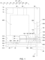
- Fig. 1 is a schematic illustration of examples of circular saws 10 according to the present disclosure
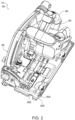
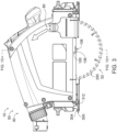
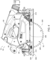
- Figs. 2-10 are less schematic illustrations of an example of a circular saw 10 according to the present disclosure, in the form of a plunge saw 30.
- Fig. 2 illustrates a top profile view of circular saw 10
- Fig. 3 illustrates a right side view of circular saw 10.
- Fig. 4 illustrates a left side view of circular saw 10 illustrating the circular saw in a fully plunged orientation 52
- Fig. 5 illustrates the left side view of circular saw 10 illustrating the circular saw in a fully retracted orientation 54
- Fig. 6 illustrates the left side view of Fig. 5 with several covers removed.
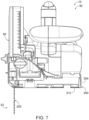
- Fig. 7 is a front view of circular saw 10
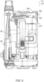
- Fig. 8 is a rear view of circular saw
- Fig. 9 is a top view of circular saw 10
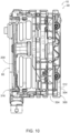
- Fig. 10 is a bottom view of circular saw 10.
- circular saws 10 include a motor 90 that includes a motor shaft 92 configured to rotate about a shaft axis of rotation 94.
- Circular saws 10 also include an arbor 100 configured to receive a torque from motor 90 when motor shaft 92 rotates about the shaft rotational axis.
- circular saws 10 also may include a circular saw blade 200.
- Circular saw blade 200 when present, may be operatively attached to the circular saw via arbor 100 and/or may be configured for rotational movement with the arbor. Rotation of circular saw blade 200 may facilitate cutting of a workpiece 98 with the circular saw blade, as schematically illustrated in Fig. 1 .
- Circular saws 10 may include any suitable type or style of circular saw that is adapted, configured, designed, and/or constructed to utilize a circular saw blade 200 to cut the workpiece.
- Examples of circular saws 10 include a handheld circular saw 12, a miter saw 14, a radial arm saw 16, a table saw 18, a chop saw 20, an upcut saw 22, a panel saw 24, a plunge saw 30, a track saw 40, and/or a bevel saw 50, as schematically illustrated in Fig. 1 .
- circular saws 10 may include structures and/or features from two or more of the above saws, and/or may incorporate functionality of two or more of the above saws.
- a given circular saw 10 may be and/or may incorporate functionality of handheld circular saw 12, plunge saw 30, track saw 40, and/or bevel saw 50.
- Circular saws 10 according to the present disclosure thus may include one or more of the features disclosed herein, but circular saws 10 are not required to include all of the features disclosed herein.
- Motor 90 may include any suitable structure that may provide the motive force for rotation of motor shaft 92 and/or for actuation of circular saw blade 200.
- Examples of motor 90 include an electric motor, an AC electric motor, a DC electric motor, a brushless DC motor, a variable-speed motor, and/or a single-speed motor.
- circular saws 10 may include a gripping region 60 that is configured to be gripped and/or held by a user during operation of the circular saw.
- Gripping region 60 when present, also may be referred to herein as and/or may be a handle, or hand grip.
- circular saws 10 may include at least one switch 65.
- Switch(es) 65 when present, may be configured to be selectively actuated by the user of the circular saw, such as to enable and/or permit electric current to be provided to at least one other component of the circular saw and/or to permit powered operation of the at least one other component of the circular saw.
- selective actuation of switch(es) 65 may be utilized to enable operation of a motor controller of the circular saw, to selectively apply an electric current to motor 90, to enable the motor controller to selectively apply the electric current to the motor, and/or to permit, or direct, the motor to provide the motive force for rotation of the motor shaft.
- the electric current may be utilized to power, or to directly power, at least one other component of the circular saw, such as motor 90.
- the electric current also may be referred to herein as an electric power signal.
- the electric current may be an electric data signal that is sent to at least one other component of the circular saw, such as the motor controller of the circular saw.
- the electric current also may be referred to herein as a data signal and/or as an electric data signal.
- Examples of switch 65 include an electrical switch, a normally open electrical switch, a momentary electrical switch, and/or a locking momentary electrical switch.
- circular saws 10 may include a workpiece support 300.
- Workpiece support 300 when present, may be configured to support workpiece 98 and/or to position the circular saw relative to the workpiece when the workpiece is cut or otherwise acted upon by the implement.
- many circular saws 10 in the form of saws include workpiece support 300 in the form of a base plate, table, shoe, rack, or pad.
- Circular saws 10 may include any suitable power source, and corresponding power structures, for powering motor 90.
- Examples of the power structures include a power supply structure 70, a power cord 72, and/or a battery 74, as illustrated in Fig. 1 .
- circular saws 10 may include a blade guard 80.
- Blade guard 80 when present, may be configured to cover, to house, and/or to contain at least a region of circular saw blade 200, such as to prevent, or to decrease a potential for, contact between the user and the circular saw blade.
- blade guard 80 may include a retractable region 82, as illustrated in Fig. 1 .
- the retractable region may be configured to fold, rotate, and/or otherwise retract when the circular saw is utilized to cut the workpiece.
- Retractable region 82 additionally or alternatively may be referred to as a retracting region 82 and/or a collapsing region 82.
- circular saws 10 may include and/or be plunge saw 30.
- arbor 100 may be configured to move relative to workpiece support 300, such as to selectively vary a region of circular saw blade 200 that projects from the workpiece support and/or to selectively vary a depth-of-cut of the circular saw.
- arbor 100 may be configured to pivot relative to workpiece support 300, as illustrated by the transition between a fully plunged orientation 52, such as illustrated in Figs. 3-4 and 7-8 , and a fully retracted orientation 54, such as illustrated in Figs. 5-6 .
- workpiece support 300 may include and/or be a base plate 304 that defines an arbor-facing side 308 and an arbor-opposed side 312.
- Arbor 100 may be operatively attached to arbor-facing side 308 of base plate 304 with, via, and/or utilizing a base plate pivot 316.
- arbor 100 and base plate 304 may be configured to rotate, relative to one another, about base plate pivot 316, such as to selectively vary a region 320 of circular saw blade 200 that extends on arbor-opposed side 312 of the base plate, as perhaps best illustrated by the transition from the configuration that is illustrated in Fig. 4 , which illustrates fully plunged orientation 52, to the configuration that is illustrated in Fig. 5 , which illustrates fully retracted orientation 54.
- arbor 100 may be configured to pivot relative to workpiece support 300 throughout a range of relative orientations, or relative angles, that may be bounded by the fully plunged orientation and the fully retracted orientation.
- circular saw blade 200 may extend on arbor-opposed side 312 by a corresponding amount, thereby providing a corresponding maximum depth-of-cut for the circular saw.
- circular saws 10 may include and/or be track saw 40.
- base plate 304 may include a rib-receiving channel 324, which may be configured to receive a raised elongate rib 44 of a track 42, as perhaps best illustrated in Fig. 1 .
- Track 42 also may be referred to herein as an elongate track 42 and may be formed from one or more elongate track segments, or track sections, 46, which may be operatively attached to one another to define any suitable track length.
- track 42 may be operatively attached, or clamped, to workpiece 98 such that an edge of the track corresponds to a desired cut line for the track saw.
- the track saw may be positioned, relative to the track, such that raised elongate rib 44 is positioned within rib-receiving channel 324; and the track saw then may be translated along at least a fraction of the length of the elongate track, thereby producing a straight cut along the desired cut line.
- Circular saws 10, according to the present disclosure also include a blade mount 108, which is operatively attached to arbor 100
- Figs. 11-16 are illustrations of examples of components of a circular saw 10 that emphasize examples of arbor 100 operatively attached to blade mounts 108 and/or utilized to retain circular saw blades 200, according to the present disclosure.
- Fig. 11 is a schematic illustration of examples of an arbor 100, a blade mount 108, and a circular saw blade 200 that may be utilized with circular saws 10, according to the present disclosure.
- Fig. 12 is a partially exploded profile view of an example of circular saws 10
- Fig. 13 is a cross-sectional view of circular saws 10 of Fig. 12 taken along line 13-13 of Fig. 3 .
- FIG. 14 is an exploded view illustrating arbor 100, blade mount 108, and circular saw blade 200 of circular saw 10
- Fig. 15 is an assembled view of the arbor, the blade mount, and the circular saw blade of Fig. 14
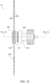
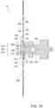
- Fig. 16 is a cross-sectional view of the arbor, the blade mount, and the circular saw blade of Fig. 14 taken along line 16-16 of Fig. 15 .
- Circular saws 10 of Figs. 11-16 may include and/or be more detailed and/or different illustrations, views, and/or examples of circular saws 10 of Figs. 1-10 .
- any of the structures, functions, and/or features disclosed herein with reference to circular saws 10 of Figs. 11-16 may be included in and/or utilized with circular saws 10 of Figs. 1-10 without departing from the scope of the present disclosure.
- any of the structures, functions, and/or features disclosed herein with reference to circular saws 10 of Figs. 1-10 may be included in and/or utilized with circular saws 10 of Figs. 11-16 without departing from the scope of the present disclosure.
- arbor 100 and/or blade mount 108 may be configured to facilitate selective and repeated separation of circular saw blade 200 from a remainder of the circular saw and/or to facilitate selective and repeated attachment, or operative attachment, of the circular saw blade to the remainder of the circular saw. This may be accomplished in any suitable manner.
- arbor 100 may include and/or be a threaded arbor 104
- blade mounts 108 may include a fastener 168 that may thread into threaded arbor 104, as illustrated in Figs. 1 and 11 .
- Arbor 100 may be configured to rotate, or to rotate circular saw blade 200, about an arbor rotational axis 106.
- Arbor rotational axis 106 may be parallel, or at least substantially parallel, to shaft axis of rotation 94 of motor shaft 92 of motor 90, as perhaps best illustrated in Figs. 1 and 13 and as discussed in more detail herein.
- circular saws 10 include blade mount 108.
- Blade mount 108 may be operatively attached to arbor 100, may be at least partially defined by arbor 100, and/or may be configured to operatively attach circular saw blade 200 to arbor 100.
- Blade mount 108 includes an inner flange 112 and may include an outer flange 136 and a fastener 168.
- Fastener 168 may be configured to threadingly engage with and/or within threaded arbor 104 and/or to selectively and/or operatively retain inner flange 112, outer flange 136, and/or circular saw blade 200 on arbor 100.
- inner flange 112 may be operatively attached to arbor 100, such as by fastener 168. In some examples, inner flange 112 may be defined by and/or may form a portion of arbor 100.
- inner flange 112 may extend radially from, or away from, arbor 100 and/or arbor rotational axis 106. As perhaps best illustrated in Figs. 11 , 13-14 and 16 , inner flange 112 may include and/or define a central inner flange opening 116, which may be configured to receive fastener 168 and/or to permit the fastener to pass therethrough. As also illustrated, inner flange 112 may be positioned proximate motor 90 relative to outer flange 136 when the blade mount is utilized to selectively and operatively attach the circular saw blade to the arbor.
- inner flange 112 may include and/or define an inner flange blade-contacting surface 120, which may be configured to contact circular saw blade 200 when the circular saw blade is selectively and operatively attached to the circular saw via blade mount 108.
- Inner flange blade-contacting surface 120 may face away from motor 90, may face away from arbor 100, and/or may face away from a remainder of arbor 100.
- Inner flange blade-contacting surface 120 may be configured for at least partial, or even complete, face-to-face contact with a planar blade surface, such as an inner planar blade surface 202, of circular saw blade 200, as perhaps best illustrated in Figs. 1 , 11 , 13 , and 15-16 .
- Inner flange 112 also may include and/or define an inner flange recessed region 128.
- the inner flange recessed region also may be referred to herein as a recessed central region 128 of the inner flange.
- inner flange recessed region 128 may be sized and/or shaped to accept and/or to interlock with an outer flange projecting region 152 of outer flange 136.
- Inner flange recessed region 128 may have and/or define a maximum inner flange recessed region dimension 132, which may be measured in and/or within an inner flange plane 124 that may be defined by, may be parallel to, and/or may be coextensive with inner flange blade-contacting surface 120, as perhaps best illustrated in Figs. 11 and 16 .
- Maximum inner flange recessed region dimension 132 may correspond to a maximum central opening dimension 216 of a central opening 212 of circular saw blade 200.
- maximum inner flange recessed region dimension 132 may be equal to maximum central opening dimension 216 and/or may be within a threshold dimension tolerance of maximum central opening dimension 216.
- the threshold dimension tolerance may be selected to provide a sliding fit between inner flange recessed region 128 and outer flange projecting region 152 and/or between central opening 212 and the outer flange projecting region 152.
- Such a configuration may permit outer flange projecting region 152 to extend through central opening 212 of circular saw blade 200 and into inner flange recessed region 128 of inner flange 112.
- Inner flange 112 may be free from any structure that projects away from a remainder of the inner flange, or away from motor 90, and that also projects away from inner flange blade-contacting surface 120. Additionally or alternatively, an entirety of inner flange 112 may be external central opening 212 of circular saw blade 200 and/or may not extend into the central opening when blade mount 108 selectively and operatively attaches the circular saw blade to the arbor. Stated another way, an entirety of inner flange 112 may be proximate arbor 100 relative to inner flange plane 124 and/or may be proximate motor 90 relative to the inner flange plane.
- blade mount 108 may be configured to permit and/or facilitate removal of the circular saw blade from the circular saw and/or attachment of the circular saw blade to the circular saw without a need to move the circular saw blade in a direction that is parallel to arbor rotational axis 106 and/or while only requiring motion of the circular saw blade in a direction that is perpendicular, or at least substantially perpendicular, to the arbor rotational axis.
- Blade mount 108 thus may be configured to permit removal and replacement of circular saw blade 200 via only radial movement of the circular saw blade relative to the inner flange, as opposed to conventional blade mounts that require both radial and translational movement of the circular saw blade.
- outer flange 136 may extend radially from, or away from, arbor 100 and/or arbor rotational axis 106. As perhaps best illustrated in Figs. 11 , 13-14 , and 16 , outer flange 136 includes and/or define a central outer flange opening 140, which is configured to receive fastener 168 and/or to permit the fastener to pass therethrough. As also illustrated, outer flange 136 may be positioned distal motor 90 relative to inner flange 112 when the blade mount is utilized to selectively and operatively attach the circular saw blade to the arbor.
- Outer flange 136 may include and/or define an outer flange recessed region 160, which may be shaped, sized, and/or configured to receive a fastener head 172 of fastener 168.
- outer flange recessed region 160 may include an outer flange shoulder 164, which may be sized to permit fastener 168 to extend at least partially through central outer flange opening 140 but to restrict fastener head 172 from extending through the central outer flange opening.
- Such a configuration may permit fastener head 172 to compress circular saw blade 200 between inner flange 112 and outer flange 136 when fastener 168 is threaded onto arbor 100.
- Outer flange 136 may have and/or define an outer flange blade-contacting surface 144, as perhaps best illustrated in Fig. 16 .
- Outer flange blade-contacting surface 144 may be configured to contact circular saw blade 200, may be configured for at least partial face-to-face contact with the circular saw blade, and/or may be configured for complete face-to-face contact with the circular saw blade and/or with an outer planar blade surface 204 of the circular saw blade when the circular saw blade is selectively and operatively attached to the circular saw.
- Outer flange blade-contacting surface 144 and outer flange recessed region 160 may be on opposed, or opposite, sides of outer flange 136.
- Outer flange blade-contacting surface 144 may face toward inner flange blade-contacting surface 120, may face toward arbor 100, and/or may face toward motor 90 when blade mount 108 selectively and operatively attaches the circular saw blade to the arbor.
- outer flange 136 includes outer flange projecting region 152.
- Outer flange projecting region 152 projects from outer flange blade-contacting surface 144 and/or away from outer flange recessed region 160.
- outer flange projecting region 152 may be sized to be received within central opening 212 of circular saw blade 200 and/or within inner flange recessed region 128 of inner flange 112.
- a maximum outer flange projecting region dimension 156 of outer flange projecting region 152 may correspond to maximum central opening dimension 216 of circular saw blade 200 and/or to maximum inner flange recessed region dimension 132 of inner flange 112, as illustrated in Fig.
- outer flange projecting region 152 may be clearanced to fit with, may be sized for a sliding fit with, and/or may be within a sliding fit tolerance of maximum central opening dimension 216 and/or maximum inner flange recessed region dimension 132.
- Maximum outer flange projecting region dimension 156 may be measured within an outer flange plane 148 that may be defined by, may be parallel to, and/or may be coextensive with outer flange blade-contacting surface 144.
- inner flange 112 may include an inner flange interlock structure 134
- outer flange 136 may include an outer flange interlock structure 166.
- Inner flange interlock structure 134 and outer flange interlock structure 166 may be configured to operatively interlock with one another, such as to resist and/or to prevent rotation of outer flange 136 relative to inner flange 112 about arbor rotational axis 106.
- inner flange interlock structure 134 and outer flange interlock structure 166 include any suitable non-circular region, non-cylindrical region, keyed region, key recess, and/or key.
- Fig. 17 is a flowchart illustrating examples of methods 1000 of selectively and operatively attaching a circular saw blade to an arbor of a circular saw, according to the present disclosure.
- the circular saws include a blade mount that is operatively attached to the arbor.
- the blade mount includes an inner flange that defines an inner flange blade-contacting surface.
- Examples of circular saws that may be utilized with methods 1000 are disclosed herein with reference to circular saws 10.
- Examples of the arbor are disclosed herein with reference to arbor 100.
- Examples of the blade mount are disclosed herein with reference to blade mounts 108.
- Examples of inner flange blade-contacting surfaces are disclosed herein with reference to inner flange blade-contacting surface 120.
- Methods 1000 include operatively aligning at 1010, positioning at 1020, and operatively retaining at 1030.
- Operatively aligning at 1010 may include operatively aligning a central opening of the circular saw blade with the inner flange. This may include operatively aligning such that an inner planar blade surface of the circular saw blade is in face-to-face contact with the inner flange blade-contacting surface.
- the operatively aligning at 1010 may include operatively aligning such that the central opening of the circular saw blade is free from any structure that projects from the inner flange, such that the central opening is free from any structure that projects from the inner flange subsequent to the operatively aligning at 1010, such that no portion of the inner flange extends into the central opening, and/or such that, subsequent to the operatively aligning at 1010, the inner flange blade-contacting surface extends radially from the central opening.
- Examples of the central opening are disclosed herein with reference to central opening 212.
- Examples of the inner planar blade surface are disclosed herein with reference to inner planar blade surface 202.
- the operatively aligning at 1010 may include operatively translating one of the circular saw blade and the inner flange relative to the other of the circular saw blade and the inner flange. This may include operatively translating within, or in some examples at least substantially only within, an inner flange plane of the inner flange blade-contacting surface. Additionally or alternatively, the operatively translating at 1010 may include operatively translating in a radial direction, or only in a radial direction, relative to an arbor rotational axis of the arbor. Examples of the inner flange plane are disclosed herein with reference to inner flange plane 124. Examples of the arbor rotational axis are disclosed herein with reference to arbor rotational axis 106.
- the inner planar blade surface is in face-to-face contact with the inner flange blade-contacting surface during at least a contact timeframe of the operatively translating. In some such examples, an entirety of the inner planar blade surface is in face-to-face contact with the inner flange blade-contacting surface during the contact timeframe and/or during at least a subset of the contact timeframe.
- the contact timeframe may include and/or be any suitable timeframe, or duration of time, during the operatively aligning at 1010.
- the contact timeframe may be prior to, or at least partially prior to, operatively aligning between the central opening and the inner flange.
- the absence of any structure that projects from the inner flange and into the central opening may permit and/or facilitate contact, face-to-face contact, and/or complete contact of the inner flange blade-contacting surface with the inner planar blade surface during relative motion between the circular saw blade and the central opening that is utilized to accomplish the operatively aligning at 1010.
- Positioning at 1020 may include positioning an outer flange of the blade mount such that an outer flange blade-contacting surface of the outer flange is in face-to-face contact with an outer planar blade surface of the circular saw blade. Additionally or alternatively, the positioning at 1020 may include positioning such that an outer flange projecting region of the outer flange extends through the central opening of the circular saw blade and/or into an inner flange recessed region of the inner flange. Examples of the outer flange are disclosed herein with reference to outer flange 136. Examples of the outer flange blade-contacting surface are disclosed herein with reference to outer flange blade-contacting surface 144. Examples of the outer flange projecting region are disclosed herein with reference to outer flange projecting region 152. Examples of the inner flange recessed region are disclosed herein with reference to inner flange recessed region 128.
- the outer flange blade-contacting surface may extend radially from the central opening of the circular saw blade. In some examples, and subsequent to the positioning at 1020, the outer flange may be positioned distal the motor relative to the inner flange and/or distal the arbor relative to the inner flange.
- Operatively retaining at 1030 may include operatively retaining the outer flange on the arbor with a fastener. Examples of the fastener are disclosed herein with reference to fastener 168.
- the operatively retaining at 1030 may include compressing the circular saw blade between the inner flange and the outer flange. In some examples, the operatively retaining at 1030 may include threading the fastener into the inner flange and/or into the arbor. In some examples, the operatively retaining at 1030 further may include operatively retaining the inner flange on the arbor with the fastener.
- the operatively retaining at 1030 may include extending the fastener through a central inner flange opening of the inner flange and also through a central outer flange opening of the outer flange.
- Examples of the central inner flange opening are disclosed herein with reference to central inner flange opening 116.
- Examples of the central outer flange opening are disclosed herein with reference to central outer flange opening 140.
- the term "and/or" placed between a first entity and a second entity means one of (1) the first entity, (2) the second entity, and (3) the first entity and the second entity.
- Multiple entities listed with “and/or” should be construed in the same manner, i.e., "one or more" of the entities so conjoined.
- Other entities may optionally be present other than the entities specifically identified by the "and/or” clause, whether related or unrelated to those entities specifically identified.
- a reference to "A and/or B,” when used in conjunction with open-ended language such as “comprising” may refer, in one embodiment, to A only (optionally including entities other than B); in another embodiment, to B only (optionally including entities other than A); in yet another embodiment, to both A and B (optionally including other entities).
- These entities may refer to elements, actions, structures, steps, operations, values, and the like.
- the phrase "at least one,” in reference to a list of one or more entities should be understood to mean at least one entity selected from any one or more of the entities in the list of entities, but not necessarily including at least one of each and every entity specifically listed within the list of entities and not excluding any combinations of entities in the list of entities.
- This definition also allows that entities may optionally be present other than the entities specifically identified within the list of entities to which the phrase "at least one" refers, whether related or unrelated to those entities specifically identified.
- At least one of A and B may refer, in one embodiment, to at least one, optionally including more than one, A, with no B present (and optionally including entities other than B); in another embodiment, to at least one, optionally including more than one, B, with no A present (and optionally including entities other than A); in yet another embodiment, to at least one, optionally including more than one, A, and at least one, optionally including more than one, B (and optionally including other entities).
- each of the expressions “at least one of A, B, and C,” “at least one of A, B, or C,” “one or more of A, B, and C,” “one or more of A, B, or C,” and “A, B, and/or C” may mean A alone, B alone, C alone, A and B together, A and C together, B and C together, A, B, and C together, and optionally any of the above in combination with at least one other entity.
- adapted and “configured” mean that the element, component, or other subject matter is designed and/or intended to perform a given function.
- the use of the terms “adapted” and “configured” should not be construed to mean that a given element, component, or other subject matter is simply “capable of” performing a given function but that the element, component, and/or other subject matter is specifically selected, created, implemented, utilized, programmed, and/or designed for the purpose of performing the function.
- elements, components, and/or other recited subject matter that is recited as being adapted to perform a particular function may additionally or alternatively be described as being configured to perform that function, and vice versa.
- the phrase, "for example,” the phrase, “as an example,” and/or simply the term “example,” when used with reference to one or more components, features, details, structures, embodiments, and/or methods according to the present disclosure, are intended to convey that the described component, feature, detail, structure, embodiment, and/or method is an illustrative, non-exclusive example of components, features, details, structures, embodiments, and/or methods according to the present disclosure.
- an object that is at least substantially formed from a material includes objects for which at least 75% of the objects are formed from the material and also includes objects that are completely formed from the material.
- a first length that is at least substantially as long as a second length includes first lengths that are within 75% of the second length and also includes first lengths that are as long as the second length.
Landscapes
- Life Sciences & Earth Sciences (AREA)
- Engineering & Computer Science (AREA)
- Mechanical Engineering (AREA)
- Wood Science & Technology (AREA)
- Forests & Forestry (AREA)
- Sawing (AREA)
- Physics & Mathematics (AREA)
- Optics & Photonics (AREA)
- Gripping On Spindles (AREA)
- Portable Power Tools In General (AREA)
Claims (15)
- Kreissäge (10), umfassend: einen Motor (90) mit einer Motorwelle (92), die dazu ausgebildet ist, sich um eine Wellendrehachse (94) zu drehen; einen Dorn (100), der dazu ausgebildet ist, ein Drehmoment von dem Motor (90) aufzunehmen, wenn sich die Motorwelle (92) um die Wellendrehachse (94) dreht; eine Sägeblattbefestigung (108), die operativ an dem Dorn (100) angebracht ist, wobei die Sägeblattbefestigung (108) ausgebildet ist, um ein Kreissägeblatt (200) selektiv und operativ an dem Dorn (100) anzubringen, wobei die Sägeblattbefestigung (108) einen inneren Flansch (112) umfasst, wobei der innere Flansch (112) eine innere Flansch-Sägeblatt-Kontaktfläche (120) aufweist, die vom Motor (90) weg weist und so ausgebildet ist, dass sie das Kreissägeblatt (200) berührt, wenn das Kreissägeblatt (200) selektiv und operativ an der Kreissäge (10) angebracht wird, und wobei der innere Flansch (112) außerdem frei von jeglicher Struktur ist, die vom Motor (90) und auch von der inneren Flansch-Sägeblatt-Kontaktfläche (120) wegragt,
dadurch gekennzeichnet, dass
die Sägeblattbefestigung (108) ferner einen äußeren Flansch (136) und ein Befestigungselement (168) umfasst, das den äußeren Flansch (136) operativ auf dem Dorn (100) hält, und dass der äußere Flansch (136) eine zentrale Öffnung (140) des äußeren Flansches umfasst und/oder definiert, die ein Befestigungselement (168) aufnimmt und/oder so ausgebildet ist, dass das Befestigungselement (168) durch sie verlaufen kann. - Kreissäge (10) nach Anspruch 1, wobei die innere Flansch-Sägeblatt-Kontaktfläche (120) für einen flächigen Kontakt mit einer ebenen Sägeblattfläche (202, 204) des Kreissägeblatts (200) ausgebildet ist und/oder wobei sich der innere Flansch (112) radial von dem Dorn (100) erstreckt.
- Kreissäge (10) nach Anspruch 1 oder 2, wobei der innere Flansch (112) relativ zum äußeren Flansch (136) nahe dem Motor (90) positioniert ist, wenn die Sägeblattbefestigung (108) das Kreissägeblatt (200) selektiv und operativ am Dorn (100) befestigt.
- Kreissäge (10) gemäß einem der Ansprüche 1 bis 3, wobei der innere Flansch (112) ferner eine zentrale Öffnung (116) des inneren Flansches aufweist, die zur Aufnahme des Befestigungselements (168) ausgebildet ist.
- Kreissäge (10) gemäß einem der Ansprüche 1 bis 4, wobei der innere Flansch (112) ferner einen inneren Flansch-Vertiefungsbereich (128) aufweist, der sich von der inneren Flansch-Sägeblatt-Kontaktfläche (120) in den inneren Flansch (112) hinein erstreckt, wobei der äußere Flansch (136) eine äußere Flansch-Sägeblatt-Kontaktfläche (144) und einen vorstehenden Bereich des äußeren Flansches (152) aufweist, der von der äußeren Flansch-Sägeblatt-Kontaktfläche (144) vorsteht, wobei der innere Flansch-Vertiefungsbereich (128) so bemessen ist, dass er den vorstehenden Bereich des äußeren Flansches aufnimmt.
- Kreissäge (10) nach einem der Ansprüche 1 bis 5, wobei der äußere Flansch (136) eine zentrale Öffnung (140) des äußeren Flansches, die zur Aufnahme des Befestigungselements (168) ausgebildet ist, und einen vertieften Bereich (160) des äußeren Flansches aufweist, der zur Aufnahme eines Kopfes (172) des Befestigungselements (168) ausgebildet ist, und wobei der vertiefte Bereich (160) des äußeren Flansches ferner eine Schulter (164) des äußeren Flansches aufweist, die so bemessen ist, dass das Befestigungselement (168) sich durch die zentrale Öffnung (140) des äußeren Flansches erstrecken kann, und dass der Kopf (172) des Befestigungselements daran gehindert wird, sich durch die zentrale Öffnung (140) des äußeren Flansches zu erstrecken.
- Kreissäge (10) von Anspruch 6.8, sofern von Anspruch 5 abhängig, wobei sich die äußere Flansch-Sägeblatt-Kontaktfläche (144) und der vertiefte Bereich des äußeren Flansches (160) auf gegenüberliegenden Seiten des äußeren Flansches (136) befinden.
- Kreissäge (10) gemäß einem der Ansprüche 1-7, wobei der äußere Flansch (136) relativ zum inneren Flansch (112) distal zum Motor (90) positioniert ist, wenn die Sägeblattbefestigung (108) das Kreissägeblatt (200) selektiv und operativ am Dorn (100) befestigt.
- Kreissäge (10) gemäß einem der Ansprüche 1-8, wobei, wenn die Sägeblattbefestigung (108) das Kreissägeblatt (200) selektiv und operativ am Dorn (100) befestigt, kein Teil des inneren Flansches (112) in eine zentrale Öffnung (212) des Kreissägeblatts (200) hineinragt.
- Verfahren zum selektiven und operativen Befestigen eines Kreissägeblatts (200) an einem Dorn (100) einer Kreissäge (10), wobei die Kreissäge (10) eine Sägeblattbefestigung (108) aufweist, wobei die Sägeblattbefestigung (108) operativ an dem Dorn (100) angebracht ist und einen inneren Flansch (112) aufweist, der eine innere Flansch-Sägeblatt-Kontaktfläche (120) definiert, wobei das Verfahren umfasst:- operatives Ausrichten einer zentralen Öffnung (212) des Kreissägeblatts (200) mit dem inneren Flansch (112), so dass eine innere ebene Sägeblattfläche (202) des Kreissägeblatts (200) in flächigem Kontakt mit der inneren Flansch-Sägeblatt-Kontaktfläche (120) steht und auch so, dass die zentrale Öffnung (212) des Kreissägeblatts (200) frei von jeglichen Strukturen ist, die vom inneren Flansch (112) hervorstehen;- Positionieren eines äußeren Flansches (136) der Sägeblattbefestigung (108), so dass eine äußere Flansch-Sägeblatt-Kontaktfläche (144) des äußeren Flansches (136) in flächigem Kontakt mit einer äußeren ebenen Sägeblattfläche (204) des Kreissägeblattes (200) steht,gekennzeichnet durch die Positionierung eines äußeren Flansches der Sägeblattbefestigung, so dass ein vorstehender Bereich (152) des äußeren Flansches (136) durch die zentrale Öffnung (212) des Kreissägeblatts (200) und in einen inneren Flansch-Vertiefungsbereich (128) des inneren Flansches (112) hineinragt; unddurch operatives Halten des äußeren Flansches (136) auf dem Dorn (100) mit einem Befestigungselement (168).
- Verfahren nach Anspruch 10, wobei das operative Ausrichten ein operatives Verschieben des inneren Flansches (112) und/oder des Sägeblatts in Bezug auf den jeweils anderen Teil, d. h. den inneren Flansch (112) oder das Sägeblatt, innerhalb einer Ebene des inneren Flansches der inneren Flansch-Sägeblatt-Kontaktfläche (120) umfasst.
- Verfahren nach Anspruch 11, wobei die innere ebene Sägeblattfläche (202) während mindestens eines Kontaktzeitraums der operativen Translationsbewegung in flächigem Kontakt mit der inneren Flansch-Sägeblatt-Kontaktfläche (120) steht.
- Verfahren nach Anspruch 12, wobei die gesamte innere ebene Sägeblattfläche (202) während des Kontaktzeitraums in flächigem Kontakt mit der inneren Flansch-Sägeblatt-Kontaktfläche (120) steht.
- Verfahren nach einem der Ansprüche 12-13, wobei der Kontaktzeitraum zumindest teilweise vor der operativen Ausrichtung zwischen der zentralen Öffnung (212) und dem inneren Flansch (112) liegt.
- Verfahren nach einem der Ansprüche 10-14, wobei sich nach dem operativen Ausrichten die innere Flansch-Sägeblatt-Kontaktfläche (120) radial von der zentralen Öffnung (212) des Kreissägeblatts (200) erstreckt und/oderwobei sich nach dem operativen Ausrichten die äußere Flansch-Sägeblatt-Kontaktfläche (144) radial von der zentralen Öffnung (212) des Kreissägeblatts (200) erstreckt, und/oderwobei der äußere Flansch (136) nach der Positionierung relativ zum inneren Flansch (112) distal zu einem Motor (90) der Kreissäge (10) positioniert ist, und/oderwobei das operative Halten das Zusammendrücken des Kreissägeblatts (200) zwischen dem inneren Flansch (112) und dem äußeren Flansch (136) umfasst, und/oder wobei das operative Halten das Erstrecken des Befestigungselements (168) durch eine zentrale Öffnung (116) des inneren Flansches des inneren Flansches (112) und auch durch eine zentrale Öffnung (140) des äußeren Flansches des äußeren Flansches (136) umfasst, und/oderwobei die Positionierung eine Positionierung nur durch radiale Bewegung des Kreissägeblatts (200) relativ zum inneren Flansch (112) umfasst.
Applications Claiming Priority (2)
| Application Number | Priority Date | Filing Date | Title |
|---|---|---|---|
| US202063044034P | 2020-06-25 | 2020-06-25 | |
| PCT/EP2021/067116 WO2021259983A1 (en) | 2020-06-25 | 2021-06-23 | Circular saw with a blade mount for circular saw blades and method of attaching a circular saw blade to a circular saw |
Publications (2)
| Publication Number | Publication Date |
|---|---|
| EP4171906A1 EP4171906A1 (de) | 2023-05-03 |
| EP4171906B1 true EP4171906B1 (de) | 2025-04-02 |
Family
ID=76662489
Family Applications (9)
| Application Number | Title | Priority Date | Filing Date |
|---|---|---|---|
| EP21735671.6A Active EP4171910B1 (de) | 2020-06-25 | 2021-06-23 | Geführte säge mit selbsteinstellendem führungssatz und betriebsverfahren |
| EP21735672.4A Active EP4171856B1 (de) | 2020-06-25 | 2021-06-23 | Tauchsäge mit schnittindikatoren und verfahren zum betrieb einer tauchsäge |
| EP21735669.0A Active EP4171906B1 (de) | 2020-06-25 | 2021-06-23 | Kreissäge mit blatthalterung für kreissägeblatt und verfahren zur befestigung eines kreissägeblatts an einer kreissäge |
| EP21735919.9A Pending EP4171912A1 (de) | 2020-06-25 | 2021-06-23 | Kreissägen mit schwenkanordnungen und schwenkvorspannmechanismen |
| EP25214630.3A Pending EP4684899A3 (de) | 2020-06-25 | 2021-06-23 | Handkreissägen mit verbesserten schneidefähigkeiten |
| EP21735918.1A Pending EP4171911A1 (de) | 2020-06-25 | 2021-06-23 | Kreissägen mit durchsichtigen fenstern, die sich in klingenschutzöffnungen erstrecken und befestigungsstrukturen abdecken |
| EP21735673.2A Active EP4171909B1 (de) | 2020-06-25 | 2021-06-23 | Handkreissägen mit verbesserten schneidefähigkeiten |
| EP21735917.3A Pending EP4171908A1 (de) | 2020-06-25 | 2021-06-23 | Schrägsägen, die so konfiguriert sind, dass sie einen schrägschnitt in einem werkstück ausführen |
| EP21735670.8A Active EP4171907B1 (de) | 2020-06-25 | 2021-06-23 | Kreissäge mit schalterschlossbaugruppen |
Family Applications Before (2)
| Application Number | Title | Priority Date | Filing Date |
|---|---|---|---|
| EP21735671.6A Active EP4171910B1 (de) | 2020-06-25 | 2021-06-23 | Geführte säge mit selbsteinstellendem führungssatz und betriebsverfahren |
| EP21735672.4A Active EP4171856B1 (de) | 2020-06-25 | 2021-06-23 | Tauchsäge mit schnittindikatoren und verfahren zum betrieb einer tauchsäge |
Family Applications After (6)
| Application Number | Title | Priority Date | Filing Date |
|---|---|---|---|
| EP21735919.9A Pending EP4171912A1 (de) | 2020-06-25 | 2021-06-23 | Kreissägen mit schwenkanordnungen und schwenkvorspannmechanismen |
| EP25214630.3A Pending EP4684899A3 (de) | 2020-06-25 | 2021-06-23 | Handkreissägen mit verbesserten schneidefähigkeiten |
| EP21735918.1A Pending EP4171911A1 (de) | 2020-06-25 | 2021-06-23 | Kreissägen mit durchsichtigen fenstern, die sich in klingenschutzöffnungen erstrecken und befestigungsstrukturen abdecken |
| EP21735673.2A Active EP4171909B1 (de) | 2020-06-25 | 2021-06-23 | Handkreissägen mit verbesserten schneidefähigkeiten |
| EP21735917.3A Pending EP4171908A1 (de) | 2020-06-25 | 2021-06-23 | Schrägsägen, die so konfiguriert sind, dass sie einen schrägschnitt in einem werkstück ausführen |
| EP21735670.8A Active EP4171907B1 (de) | 2020-06-25 | 2021-06-23 | Kreissäge mit schalterschlossbaugruppen |
Country Status (6)
| Country | Link |
|---|---|
| US (8) | US20230158703A1 (de) |
| EP (9) | EP4171910B1 (de) |
| JP (8) | JP7542086B2 (de) |
| CN (10) | CN118024358A (de) |
| DE (1) | DE202021107000U1 (de) |
| WO (8) | WO2021259999A1 (de) |
Families Citing this family (8)
| Publication number | Priority date | Publication date | Assignee | Title |
|---|---|---|---|---|
| EP4171910B1 (de) * | 2020-06-25 | 2025-08-06 | Festool GmbH | Geführte säge mit selbsteinstellendem führungssatz und betriebsverfahren |
| WO2022109381A1 (en) * | 2020-11-23 | 2022-05-27 | Milwaukee Electric Tool Corporation | Track saw assembly |
| US12465982B2 (en) | 2022-02-24 | 2025-11-11 | Techtronic Cordless Gp | Track saw including plunge lockout mechanism |
| DE102022205095A1 (de) * | 2022-05-23 | 2023-11-23 | Robert Bosch Gesellschaft mit beschränkter Haftung | Werkzeugmaschinenvorrichtung, Werkzeugmaschine und System |
| US11897114B1 (en) | 2022-08-16 | 2024-02-13 | Techtronic Cordless Gp | Accessory storage location for power tool |
| USD1055655S1 (en) | 2022-08-16 | 2024-12-31 | Techtronic Cordless Gp | Power tool |
| US12083613B2 (en) | 2022-10-18 | 2024-09-10 | Techtronic Cordless Gp | Track saw including plunge lockout mechanism |
| DE112023004574T5 (de) * | 2022-11-01 | 2025-09-04 | Koki Holdings Co., Ltd. | Arbeitsmaschine |
Family Cites Families (160)
| Publication number | Priority date | Publication date | Assignee | Title |
|---|---|---|---|---|
| US1830579A (en) * | 1930-01-30 | 1931-11-03 | Wappat Inc | Electric handsaw |
| DE743056C (de) | 1942-03-28 | 1943-12-17 | Festo Maschf Stoll G | Handkreissaege |
| US2562396A (en) * | 1947-03-15 | 1951-07-31 | Walt Inc De | Safety device for saws |
| DE838951C (de) | 1948-10-02 | 1952-05-15 | Festo Maschf Stoll G | Handkreissaege |
| DE834897C (de) * | 1949-11-01 | 1952-03-24 | Eugen Lutz Holzbearbeitungsmas | Kreissaege mit Motorantrieb, die beim Arbeiten von Hand angesetzt und gefuehrt wird und deren Saegeblatt durch Schwenken des Motorgehaeuses in auf einer Grundplatte vorgesehenen Zapfenlagern schraeg gestellt werden kann |
| AT183946B (de) * | 1953-10-24 | 1955-11-25 | Walter Wuhrmann | Gehrungssäge |
| US2861607A (en) * | 1955-10-24 | 1958-11-25 | Porter Cable Machine Co | Jack shaft and guard unit for wood working saws |
| US3262472A (en) * | 1964-05-08 | 1966-07-26 | Black & Decker Mfg Co | Depth and bevel adjustment means for portable power-driven saw |
| US3722496A (en) * | 1971-01-28 | 1973-03-27 | A Schuman | Concrete cutting hand saw |
| US3721141A (en) * | 1971-07-06 | 1973-03-20 | Rockwell Mfg Co | Movable blade guard and mounting for portable circular saws |
| JPS5117654Y2 (de) * | 1971-07-19 | 1976-05-12 | ||
| US3973179A (en) * | 1974-08-23 | 1976-08-03 | The Black And Decker Manufacturing Company | Modular cordless tools |
| US3971906A (en) * | 1974-11-01 | 1976-07-27 | Lucerne Products, Inc. | Trigger-lock control |
| US4022182A (en) * | 1976-01-12 | 1977-05-10 | Lenkevich Steve T | Dust and water confinement unit for portable circular saw |
| JPS52139483U (de) * | 1976-04-16 | 1977-10-22 | ||
| JPS567052Y2 (de) * | 1977-09-20 | 1981-02-16 | ||
| DE3104340C2 (de) * | 1980-03-06 | 1986-06-05 | AEG Power Tool Corp. (APTC), Norwich, Conn. | Tragbare Kreissäge |
| JPS5756109U (de) | 1980-09-16 | 1982-04-01 | ||
| DE3106098A1 (de) * | 1981-02-19 | 1982-09-02 | Eugen Lutz GmbH u. Co Maschinenfabrik, 7130 Mühlacker | Kombinierte tisch- und gehrungssaege |
| DE3341003C2 (de) | 1983-11-12 | 1986-01-30 | Festo-Maschinenfabrik Gottlieb Stoll, 7300 Esslingen | Führungseinrichtung für eine transportable Säge |
| DE3621718C2 (de) * | 1986-06-28 | 1995-04-06 | Black & Decker Inc | Motorgetriebene Kreissäge |
| US4729193A (en) * | 1986-12-22 | 1988-03-08 | Eugene Gant | Cutting disk mounting assembly |
| DE3721471A1 (de) | 1987-06-30 | 1989-01-12 | Eisele Maschf Chr | Kreissaegemaschine |
| US4879438A (en) * | 1988-08-01 | 1989-11-07 | Ryobi Motor Products Corp. | Lock-on/lock-off switch for power tool |
| US4892022A (en) * | 1988-09-20 | 1990-01-09 | Robert Bosch Power Tool Corporation | Safety guard for sawing power tool particularly mitre saw |
| JPH0737782Y2 (ja) * | 1989-12-15 | 1995-08-30 | 日立工機株式会社 | 電気丸鋸のベース傾斜機構 |
| US5010651A (en) * | 1990-07-10 | 1991-04-30 | Skil Corporation | Portable circular saw |
| JPH04269502A (ja) * | 1991-02-25 | 1992-09-25 | Matsushita Electric Works Ltd | 電動刃物機器 |
| DE4124234A1 (de) * | 1991-07-22 | 1993-01-28 | Bosch Gmbh Robert | Handkreissaege und saegeverfahren |
| DE4124233A1 (de) * | 1991-07-22 | 1993-01-28 | Bosch Gmbh Robert | Handkreissaege |
| US5235753A (en) * | 1992-03-20 | 1993-08-17 | Black & Decker Inc. | Circular saw lower guard chip deflector |
| US5303688A (en) * | 1992-04-03 | 1994-04-19 | Chiuminatta Edward R | Mounting arbor for saw cutting blades |
| JP3336036B2 (ja) * | 1992-05-26 | 2002-10-21 | 松下電工株式会社 | 電動丸鋸 |
| FI91136C (fi) * | 1992-07-03 | 1994-05-25 | Kauko Rautio | Pyöröterän kiinnitysjärjestelmä |
| GB9316724D0 (en) * | 1993-08-12 | 1993-09-29 | Black & Decker Inc | Pivot bearing for a chop saw |
| US5406752A (en) * | 1993-09-13 | 1995-04-18 | American Pneumatic Technologies | Reversible sander |
| JPH08177813A (ja) * | 1994-12-22 | 1996-07-12 | Power Tool Holders Inc | 締付け用ネジ |
| US5588213A (en) | 1995-03-07 | 1996-12-31 | Swanberg; Alan M. | Circular saw with dust trapper |
| US5794351A (en) * | 1996-05-31 | 1998-08-18 | Black & Decker, Inc. | Window assembly and lower saw guard for circular saw |
| US5822864A (en) * | 1996-05-31 | 1998-10-20 | Black & Decker, Inc. | Viewing window for circular saw guard |
| US5718621A (en) * | 1996-09-11 | 1998-02-17 | Turley; Edward Michael | Reversible angle grinder with top arbour lock |
| US5856715A (en) * | 1996-12-13 | 1999-01-05 | Ryobi North America, Inc. | Portable electrical power tool having a rare earth permanent magnet motor |
| US6093090A (en) * | 1998-01-28 | 2000-07-25 | The Stanley Works | Reversible clamping hub |
| US6091035A (en) * | 1998-08-14 | 2000-07-18 | Black & Decker, Inc. | Lockout mechanism for power tool |
| US6202311B1 (en) * | 1999-07-30 | 2001-03-20 | Black & Decker Inc. | Circular saw with bevel angle adjustment mechanism |
| DE29922107U1 (de) | 1999-12-16 | 2000-02-17 | Hilti Ag, Schaan | Handkreissäge |
| WO2001052384A1 (en) * | 2000-01-07 | 2001-07-19 | Black & Decker Inc. | Brushless dc motor |
| DE10032294B4 (de) * | 2000-07-03 | 2005-10-13 | Hilti Ag | Werkzeugmaschine für Trennarbeiten |
| JP4119601B2 (ja) | 2000-07-07 | 2008-07-16 | 日立工機株式会社 | 携帯用丸鋸 |
| US6561063B1 (en) * | 2000-08-18 | 2003-05-13 | Campbell Hausfeld/Scott Fetzer Company | Hand-held rotary cut-off tool |
| JP4269502B2 (ja) | 2000-09-07 | 2009-05-27 | 三菱マテリアル株式会社 | データキャリア |
| DE20017862U1 (de) * | 2000-10-18 | 2001-02-08 | FESTO Tooltechnic GmbH & Co., 73728 Esslingen | Führungsvorrichtung für eine Werkzeugmaschine |
| DE20100087U1 (de) * | 2001-01-04 | 2001-03-15 | FESTO Tooltechnic GmbH & Co., 73728 Esslingen | Handkreissäge |
| US6543143B2 (en) * | 2001-04-06 | 2003-04-08 | Black & Decker Inc. | Metal cutting circular saw with integral sight window |
| US6755107B2 (en) | 2001-05-18 | 2004-06-29 | One World Technologies Lmt. | Miter saw having a light beam alignment system |
| DE10141454A1 (de) * | 2001-08-23 | 2003-03-13 | Hilti Ag | Batteriebetriebene Kreissäge |
| JP2003071803A (ja) | 2001-08-31 | 2003-03-12 | Ryobi Ltd | 丸 鋸 |
| US7096587B2 (en) * | 2001-09-07 | 2006-08-29 | Hitachi Koki Co., Ltd. | Portable circular power saw with optical alignment |
| DE20117159U1 (de) * | 2001-10-16 | 2002-02-14 | C. & E. Fein GmbH & Co KG, 70176 Stuttgart | Werkzeugmaschine mit Befestigungsflansch |
| US6584695B1 (en) * | 2002-01-02 | 2003-07-01 | Chin-Chin Chang | Laser alignment device of a circular saw |
| US7159497B2 (en) | 2002-01-25 | 2007-01-09 | Eastway Fair Company Ltd. | Light beam alignment system |
| NL1020056C2 (nl) * | 2002-02-25 | 2003-08-27 | Skil Europ Bv | Motor en overbrengingsconstructie voor een handgereedschap. |
| US20070180710A1 (en) * | 2002-04-03 | 2007-08-09 | Keith Moore | Metal cutting circular saw with integral sight window |
| CN2561565Y (zh) * | 2002-05-14 | 2003-07-23 | 南京泉峰国际贸易有限公司 | 带激光对准装置的电圆锯 |
| JP4656806B2 (ja) * | 2002-11-01 | 2011-03-23 | 株式会社マキタ | 電動工具 |
| US7062817B2 (en) * | 2003-03-14 | 2006-06-20 | Winia Mando, Inc. | Hinge assembly structure for opening and closing of door of storage facility |
| JP2004345256A (ja) | 2003-05-23 | 2004-12-09 | Hitachi Koki Co Ltd | 携帯用切断機 |
| DE10356051A1 (de) * | 2003-12-01 | 2005-06-23 | Robert Bosch Gmbh | Handwerkzeugmaschine |
| CN100473509C (zh) * | 2004-01-16 | 2009-04-01 | 罗伯特·博世有限公司 | 切削斜角和深度锁止系统 |
| US6905401B1 (en) * | 2004-05-07 | 2005-06-14 | Sunmatch Industrial Co., Ltd. | Bi-directional rotation pneumatic grinding tool |
| WO2005118195A2 (en) | 2004-05-28 | 2005-12-15 | Scientific Molding Corporation Ltd. | Hand-held circular saw, in particular plunge-cut saw |
| CN2734387Y (zh) * | 2004-08-23 | 2005-10-19 | 周海生 | 一种电圆锯 |
| DK1640118T3 (da) * | 2004-09-22 | 2008-03-17 | Black & Decker Inc | Låsbar triggerknap til borehammer |
| US20060156887A1 (en) * | 2005-01-14 | 2006-07-20 | Robert Hutchings | Circular saw guard and foot |
| US20060185492A1 (en) * | 2005-02-18 | 2006-08-24 | Francois Chianese | Shoulder bushing for saw blades |
| DE602005010404D1 (de) | 2005-06-01 | 2008-11-27 | Black & Decker Inc | Kreissäge mit Anti-Rückschlagmittel |
| JP4762607B2 (ja) | 2005-06-01 | 2011-08-31 | 株式会社マキタ | 切断機の案内装置 |
| EP1842635B1 (de) * | 2005-06-01 | 2016-06-15 | Black & Decker, Inc. | Rückschlagsicherung für eine Kreissäge |
| DE102006025137B4 (de) * | 2005-06-01 | 2013-08-08 | Makita Corp. | Schneidwerkzeuge und Führungseinrichtung |
| JP4954504B2 (ja) * | 2005-06-28 | 2012-06-20 | 株式会社マキタ | 携帯丸鋸 |
| JP4804823B2 (ja) | 2005-07-26 | 2011-11-02 | 株式会社マキタ | 携帯丸鋸 |
| US20070107235A1 (en) * | 2005-11-15 | 2007-05-17 | Eastway Fair Company Limited Of Trident Chambers | Light assembly for circular saw |
| JP4780524B2 (ja) * | 2006-02-22 | 2011-09-28 | 日立工機株式会社 | 携帯用切断機 |
| DE202006007224U1 (de) | 2006-04-28 | 2007-07-05 | Schmid & Wezel Gmbh & Co. | Antriebseinheit mit einem rotierenden Sägeblatt zum Anschluss an einen Roboter |
| WO2008008429A1 (en) * | 2006-07-13 | 2008-01-17 | Eastway Fair Company Limited | Portable power tool for cutting concrete board and other substrates |
| US20080017005A1 (en) * | 2006-07-18 | 2008-01-24 | Hsin-Chih Tung | Light path molding apparatus of cutting machine tool |
| JP5275044B2 (ja) | 2007-01-09 | 2013-08-28 | 株式会社マキタ | 回転刃具の固定装置 |
| DE102007010249A1 (de) * | 2007-03-02 | 2008-09-04 | Festool Gmbh | Hand-Werkzeugmaschine mit einer Führungsplatte |
| JP4964642B2 (ja) | 2007-03-27 | 2012-07-04 | 株式会社マキタ | 回転刃具の固定装置 |
| JP4936220B2 (ja) * | 2007-04-19 | 2012-05-23 | 日立工機株式会社 | 電動工具 |
| EP2018936B1 (de) * | 2007-07-26 | 2010-07-14 | BLACK & DECKER INC. | Fußplatte |
| CN201346645Y (zh) * | 2007-09-13 | 2009-11-18 | 布莱克和戴克公司 | 圆锯 |
| US8695224B2 (en) | 2007-09-13 | 2014-04-15 | Black & Decker Inc. | Saw with increased depth of cut |
| GB0719802D0 (en) * | 2007-10-04 | 2007-11-21 | Black & Decker Inc | A Power tool |
| US8198560B2 (en) * | 2009-01-09 | 2012-06-12 | Makita Corporation | Switch devices for power tools |
| DE202009001440U1 (de) | 2009-01-30 | 2010-07-01 | C. & E. Fein Gmbh | Kraftgetriebenes Handwerkzeug mit Spanneinrichtung für ein Werkzeug |
| WO2010124293A1 (en) * | 2009-04-24 | 2010-10-28 | Martin Charles B | Portable cutting device with on-board debris collection |
| US8435437B2 (en) | 2009-09-04 | 2013-05-07 | Abbott Cardiovascular Systems Inc. | Setting laser power for laser machining stents from polymer tubing |
| CN102114555B (zh) | 2010-01-04 | 2014-05-28 | 泉峰(中国)贸易有限公司 | 电动工具 |
| JP5510887B2 (ja) * | 2010-01-13 | 2014-06-04 | 日立工機株式会社 | 電動工具 |
| US8776657B2 (en) * | 2010-01-26 | 2014-07-15 | Robert Bosch Gmbh | Blade mounting assembly |
| GB201003262D0 (en) * | 2010-02-26 | 2010-04-14 | 7Rdd Ltd | Saw guard means and method of use thereof |
| US8479401B2 (en) | 2010-06-15 | 2013-07-09 | Robert Bosch Gmbh | Power tool with virtual pivot |
| US20120079931A1 (en) | 2010-10-01 | 2012-04-05 | Joel Hansen | Track Saw System |
| GB201102368D0 (en) * | 2011-02-10 | 2011-03-30 | 7Rdd Ltd | Powered circular saw and method of use thereof |
| CN103402682B (zh) * | 2011-02-28 | 2016-09-07 | 株式会社牧田 | 切断工具 |
| EP2776195B1 (de) * | 2011-09-01 | 2017-08-23 | Robert Bosch GmbH | Mit bürstenlosem gleichstrommotor angetriebene kreissäge |
| US9434015B2 (en) * | 2011-09-30 | 2016-09-06 | Robert Bosch Gmbh | Saw assembly with bevel gear drivetrain |
| US8857067B2 (en) * | 2011-09-30 | 2014-10-14 | Robert Bosch Gmbh | Saw assembly with floating bearing for worm drive and motor shaft |
| US20130167383A1 (en) * | 2011-12-30 | 2013-07-04 | Robert Bosch Gmbh | Substrate specific cutting guide |
| US9044869B2 (en) * | 2012-02-06 | 2015-06-02 | Chervon (Hk) Limited | Electric circular saw |
| DE102012219397A1 (de) * | 2012-07-04 | 2014-01-09 | Robert Bosch Gmbh | Schnittlängenanzeigevorrichtung |
| JP5962309B2 (ja) | 2012-07-31 | 2016-08-03 | 日立工機株式会社 | 切断機 |
| US9610704B2 (en) * | 2012-12-11 | 2017-04-04 | Robert Bosch Tool Corporation | Circular saw blade guard with scratch-resistant panel |
| JP2014166745A (ja) * | 2013-01-30 | 2014-09-11 | Makita Corp | 充電式切断工具 |
| CN104014868B (zh) * | 2013-03-01 | 2017-09-26 | 博世电动工具(中国)有限公司 | 圆锯 |
| CN203380425U (zh) * | 2013-07-09 | 2014-01-08 | 南京久驰机电实业有限公司 | 一种电圆锯 |
| CN103418836B (zh) * | 2013-08-02 | 2016-01-20 | 江苏苏美达五金工具有限公司 | 一种带有滑动导轨的手持电动工具 |
| DE102013020723B4 (de) | 2013-12-07 | 2024-05-08 | Festool Gmbh | Hand-Werkzeugmaschine mit einer Sicherungseinrichtung |
| JP6347599B2 (ja) * | 2013-12-09 | 2018-06-27 | 株式会社マキタ | 携帯用マルノコ |
| CN203650629U (zh) * | 2013-12-30 | 2014-06-18 | 邹建静 | 带多切割锯片的木料切割机锯片装配机构 |
| EP2907634A1 (de) * | 2014-02-14 | 2015-08-19 | HILTI Aktiengesellschaft | Gehrungswinkelanschlag |
| JP6234861B2 (ja) | 2014-03-26 | 2017-11-22 | 株式会社マキタ | 電動工具用トリガスイッチ |
| JP6421495B2 (ja) * | 2014-08-27 | 2018-11-14 | マックス株式会社 | 携帯用切断機 |
| US20160121513A1 (en) * | 2014-10-30 | 2016-05-05 | Robert Bosch Tool Corporation | Lower Blade Guard for a Circular Saw |
| DE102014224571A1 (de) * | 2014-12-02 | 2016-06-02 | Robert Bosch Gmbh | Schnittlängenanzeigevorrichtung |
| JP2017024116A (ja) | 2015-07-21 | 2017-02-02 | 株式会社マキタ | 加工機 |
| JP6596249B2 (ja) * | 2015-07-21 | 2019-10-23 | 株式会社マキタ | 加工機 |
| JP2017064854A (ja) | 2015-09-30 | 2017-04-06 | 日立工機株式会社 | レールアダプタ、レールアダプタ付き切断工具、及びガイド装置付き切断工具 |
| DE102015221637A1 (de) * | 2015-11-04 | 2017-05-04 | Robert Bosch Gmbh | 21Schnittlängenanzeigevorrichtung |
| CN205309881U (zh) | 2015-12-14 | 2016-06-15 | 河北吉美达工具股份有限公司 | 一种圆锯片中心精确定位装置 |
| CN205312467U (zh) | 2016-01-28 | 2016-06-15 | 广州市行天自动化设备有限公司 | 一种自动输送线载具无隙式定位传送结构 |
| JP2017196853A (ja) | 2016-04-28 | 2017-11-02 | 日立工機株式会社 | 切断工具及びサブベース |
| WO2017208708A1 (ja) * | 2016-05-31 | 2017-12-07 | 日立工機株式会社 | 丸鋸 |
| US10543542B2 (en) * | 2016-07-27 | 2020-01-28 | Tti (Macao Commercial Offshore) Limited | Miter saw |
| US20180036900A1 (en) * | 2016-08-02 | 2018-02-08 | Cuz-D Manufacturing, Inc., Dba Cuzdey R&D | Arbors for circular saws and associated systems and methods |
| US10668644B2 (en) * | 2016-09-01 | 2020-06-02 | Makita Corporation | Portable cutting devices |
| US20180093335A1 (en) * | 2016-10-04 | 2018-04-05 | Tti (Macao Commercial Offshore) Limited | Trigger lock for a miter saw |
| US11007586B2 (en) * | 2016-12-28 | 2021-05-18 | Koki Holdings Co., Ltd. | Portable cutter |
| CN206445286U (zh) * | 2017-01-22 | 2017-08-29 | 南京德朔实业有限公司 | 电圆锯 |
| JP6918553B2 (ja) | 2017-04-05 | 2021-08-11 | 株式会社マキタ | 携帯用加工機 |
| JP2018187702A (ja) * | 2017-04-28 | 2018-11-29 | 工機ホールディングス株式会社 | 電動工具 |
| WO2018229563A1 (en) * | 2017-06-12 | 2018-12-20 | Brevetti Montolit S.P.A. | Improved handheld motorized cutting device and relative accessory |
| CN207310133U (zh) * | 2017-08-22 | 2018-05-04 | 中建八局第一建设有限公司 | 一种新型切割机锯片防护罩 |
| DE102017129811A1 (de) * | 2017-09-29 | 2019-04-04 | Festool Gmbh | Mobile Werkzeugmaschine |
| DE102017129809A1 (de) * | 2017-09-29 | 2019-04-04 | Festool Gmbh | Mobile Werkzeugmaschine |
| WO2019114777A1 (zh) * | 2017-12-13 | 2019-06-20 | 南京德朔实业有限公司 | 电圆锯 |
| DE102017222662A1 (de) | 2017-12-13 | 2019-06-13 | Robert Bosch Gmbh | Handwerkzeugmaschine |
| JP7061915B2 (ja) | 2018-04-19 | 2022-05-02 | 京セラインダストリアルツールズ株式会社 | 丸鋸 |
| DE102018112324B4 (de) * | 2018-05-23 | 2023-12-14 | Metabowerke Gmbh | Handwerkzeugmaschine mit einem Führungskörper und einem Verstellmechanismus für den Führungskörper |
| DE102019206810A1 (de) * | 2018-05-31 | 2019-12-05 | Bosch Limited | Eine Halteanordnung für ein Kreissägewerkzeug |
| DE102019108793A1 (de) * | 2018-06-12 | 2019-12-12 | Festool Gmbh | Hand-Werkzeugmaschine |
| CN208866497U (zh) * | 2018-08-23 | 2019-05-17 | 创科(澳门离岸商业服务)有限公司 | 切入式圆锯 |
| DE102018125423B4 (de) * | 2018-10-15 | 2020-11-05 | Metabowerke Gmbh | Werkzeugmaschinensystem |
| JP7249797B2 (ja) * | 2019-02-08 | 2023-03-31 | 株式会社マキタ | 携帯用加工機 |
| CN210256539U (zh) | 2019-03-06 | 2020-04-07 | 创科(澳门离岸商业服务)有限公司 | 导向调节机构以及具有该机构的电动切割工具 |
| DE102019134417A1 (de) | 2019-12-13 | 2021-06-17 | Festool Gmbh | Mobile Hand-Sägemaschine mit Vorritzaggregat und Handgriff |
| EP4171910B1 (de) * | 2020-06-25 | 2025-08-06 | Festool GmbH | Geführte säge mit selbsteinstellendem führungssatz und betriebsverfahren |
| US11613040B2 (en) * | 2020-12-11 | 2023-03-28 | Techtronic Cordless Gp | Circular saw with adjustable base |
| JP2025087112A (ja) | 2023-11-29 | 2025-06-10 | 日本ポリプロ株式会社 | ポリプロピレン樹脂組成物および無機物質粉末含有繊維 |
-
2021
- 2021-06-23 EP EP21735671.6A patent/EP4171910B1/de active Active
- 2021-06-23 CN CN202410241744.6A patent/CN118024358A/zh active Pending
- 2021-06-23 JP JP2022577545A patent/JP7542086B2/ja active Active
- 2021-06-23 CN CN202180043156.6A patent/CN115916494A/zh active Pending
- 2021-06-23 WO PCT/EP2021/067136 patent/WO2021259999A1/en not_active Ceased
- 2021-06-23 CN CN202180037321.7A patent/CN115666835B/zh active Active
- 2021-06-23 WO PCT/EP2021/067123 patent/WO2021259990A1/en not_active Ceased
- 2021-06-23 US US17/919,643 patent/US20230158703A1/en active Pending
- 2021-06-23 CN CN202180045661.4A patent/CN115803165A/zh active Pending
- 2021-06-23 EP EP21735672.4A patent/EP4171856B1/de active Active
- 2021-06-23 JP JP2022577498A patent/JP7569868B2/ja active Active
- 2021-06-23 CN CN202180045648.9A patent/CN115734856B/zh active Active
- 2021-06-23 WO PCT/EP2021/067122 patent/WO2021259989A2/en not_active Ceased
- 2021-06-23 EP EP21735669.0A patent/EP4171906B1/de active Active
- 2021-06-23 CN CN202180045617.3A patent/CN115734858A/zh active Pending
- 2021-06-23 US US17/919,568 patent/US20230166424A1/en active Pending
- 2021-06-23 US US17/919,648 patent/US12427693B2/en active Active
- 2021-06-23 CN CN202180045260.9A patent/CN115776933B/zh active Active
- 2021-06-23 WO PCT/EP2021/067120 patent/WO2021259987A1/en not_active Ceased
- 2021-06-23 EP EP21735919.9A patent/EP4171912A1/de active Pending
- 2021-06-23 JP JP2022577492A patent/JP7634023B2/ja active Active
- 2021-06-23 EP EP25214630.3A patent/EP4684899A3/de active Pending
- 2021-06-23 US US17/919,654 patent/US12420445B2/en active Active
- 2021-06-23 EP EP21735918.1A patent/EP4171911A1/de active Pending
- 2021-06-23 CN CN202180045681.1A patent/CN115734857B/zh active Active
- 2021-06-23 US US17/919,614 patent/US12420444B2/en active Active
- 2021-06-23 JP JP2022577481A patent/JP7635273B2/ja active Active
- 2021-06-23 US US17/919,612 patent/US11980955B2/en active Active
- 2021-06-23 JP JP2022577497A patent/JP7603721B2/ja active Active
- 2021-06-23 WO PCT/EP2021/067139 patent/WO2021260001A1/en not_active Ceased
- 2021-06-23 EP EP21735673.2A patent/EP4171909B1/de active Active
- 2021-06-23 EP EP21735917.3A patent/EP4171908A1/de active Pending
- 2021-06-23 WO PCT/EP2021/067133 patent/WO2021259998A1/en not_active Ceased
- 2021-06-23 WO PCT/EP2021/067116 patent/WO2021259983A1/en not_active Ceased
- 2021-06-23 WO PCT/EP2021/067125 patent/WO2021259992A2/en not_active Ceased
- 2021-06-23 CN CN202180045670.3A patent/CN115867420A/zh active Pending
- 2021-06-23 JP JP2022577519A patent/JP7534450B2/ja active Active
- 2021-06-23 JP JP2022577475A patent/JP7635272B2/ja active Active
- 2021-06-23 CN CN202410244487.1A patent/CN118024359A/zh active Pending
- 2021-06-23 US US17/919,638 patent/US20230182219A1/en active Pending
- 2021-06-23 EP EP21735670.8A patent/EP4171907B1/de active Active
- 2021-06-23 US US17/919,618 patent/US20230158702A1/en active Pending
- 2021-06-23 JP JP2022577494A patent/JP7770345B2/ja active Active
- 2021-12-22 DE DE202021107000.5U patent/DE202021107000U1/de active Active
Also Published As
Similar Documents
| Publication | Publication Date | Title |
|---|---|---|
| EP4171906B1 (de) | Kreissäge mit blatthalterung für kreissägeblatt und verfahren zur befestigung eines kreissägeblatts an einer kreissäge | |
| EP3581308A1 (de) | Gehrungssäge | |
| CN208787660U (zh) | 一种切割装置 | |
| EP2753458B1 (de) | Anordnung mit einer gehrungssäge und einer werkstückhaltevorrichtung | |
| CN210649455U (zh) | 加工辅具设备 | |
| CN217167251U (zh) | 一种硬质合金刀具加工用焊机 | |
| CN206273551U (zh) | 可防止工件剥裂的木工机械 |
Legal Events
| Date | Code | Title | Description |
|---|---|---|---|
| STAA | Information on the status of an ep patent application or granted ep patent |
Free format text: STATUS: UNKNOWN |
|
| STAA | Information on the status of an ep patent application or granted ep patent |
Free format text: STATUS: THE INTERNATIONAL PUBLICATION HAS BEEN MADE |
|
| PUAI | Public reference made under article 153(3) epc to a published international application that has entered the european phase |
Free format text: ORIGINAL CODE: 0009012 |
|
| STAA | Information on the status of an ep patent application or granted ep patent |
Free format text: STATUS: REQUEST FOR EXAMINATION WAS MADE |
|
| 17P | Request for examination filed |
Effective date: 20230125 |
|
| AK | Designated contracting states |
Kind code of ref document: A1 Designated state(s): AL AT BE BG CH CY CZ DE DK EE ES FI FR GB GR HR HU IE IS IT LI LT LU LV MC MK MT NL NO PL PT RO RS SE SI SK SM TR |
|
| DAV | Request for validation of the european patent (deleted) | ||
| DAX | Request for extension of the european patent (deleted) | ||
| REG | Reference to a national code |
Ref country code: DE Ref legal event code: R079 Free format text: PREVIOUS MAIN CLASS: B27B0005300000 Ipc: B23D0047020000 Ref document number: 602021028529 Country of ref document: DE |
|
| GRAP | Despatch of communication of intention to grant a patent |
Free format text: ORIGINAL CODE: EPIDOSNIGR1 |
|
| STAA | Information on the status of an ep patent application or granted ep patent |
Free format text: STATUS: GRANT OF PATENT IS INTENDED |
|
| RIC1 | Information provided on ipc code assigned before grant |
Ipc: B27B 9/02 20060101ALI20250113BHEP Ipc: B23D 47/02 20060101AFI20250113BHEP |
|
| GRAS | Grant fee paid |
Free format text: ORIGINAL CODE: EPIDOSNIGR3 |
|
| INTG | Intention to grant announced |
Effective date: 20250124 |
|
| GRAA | (expected) grant |
Free format text: ORIGINAL CODE: 0009210 |
|
| STAA | Information on the status of an ep patent application or granted ep patent |
Free format text: STATUS: THE PATENT HAS BEEN GRANTED |
|
| AK | Designated contracting states |
Kind code of ref document: B1 Designated state(s): AL AT BE BG CH CY CZ DE DK EE ES FI FR GB GR HR HU IE IS IT LI LT LU LV MC MK MT NL NO PL PT RO RS SE SI SK SM TR |
|
| REG | Reference to a national code |
Ref country code: GB Ref legal event code: FG4D |
|
| REG | Reference to a national code |
Ref country code: CH Ref legal event code: EP |
|
| REG | Reference to a national code |
Ref country code: DE Ref legal event code: R096 Ref document number: 602021028529 Country of ref document: DE |
|
| REG | Reference to a national code |
Ref country code: IE Ref legal event code: FG4D |
|
| P01 | Opt-out of the competence of the unified patent court (upc) registered |
Free format text: CASE NUMBER: APP_15046/2025 Effective date: 20250327 |
|
| REG | Reference to a national code |
Ref country code: NL Ref legal event code: FP |
|
| PGFP | Annual fee paid to national office [announced via postgrant information from national office to epo] |
Ref country code: DE Payment date: 20250618 Year of fee payment: 5 |
|
| PGFP | Annual fee paid to national office [announced via postgrant information from national office to epo] |
Ref country code: GB Payment date: 20250618 Year of fee payment: 5 |
|
| PGFP | Annual fee paid to national office [announced via postgrant information from national office to epo] |
Ref country code: NL Payment date: 20250618 Year of fee payment: 5 |
|
| PGFP | Annual fee paid to national office [announced via postgrant information from national office to epo] |
Ref country code: FR Payment date: 20250627 Year of fee payment: 5 |
|
| PGFP | Annual fee paid to national office [announced via postgrant information from national office to epo] |
Ref country code: AT Payment date: 20250721 Year of fee payment: 5 |
|
| REG | Reference to a national code |
Ref country code: AT Ref legal event code: MK05 Ref document number: 1780818 Country of ref document: AT Kind code of ref document: T Effective date: 20250402 |
|
| PG25 | Lapsed in a contracting state [announced via postgrant information from national office to epo] |
Ref country code: FI Free format text: LAPSE BECAUSE OF FAILURE TO SUBMIT A TRANSLATION OF THE DESCRIPTION OR TO PAY THE FEE WITHIN THE PRESCRIBED TIME-LIMIT Effective date: 20250402 Ref country code: ES Free format text: LAPSE BECAUSE OF FAILURE TO SUBMIT A TRANSLATION OF THE DESCRIPTION OR TO PAY THE FEE WITHIN THE PRESCRIBED TIME-LIMIT Effective date: 20250402 Ref country code: PT Free format text: LAPSE BECAUSE OF FAILURE TO SUBMIT A TRANSLATION OF THE DESCRIPTION OR TO PAY THE FEE WITHIN THE PRESCRIBED TIME-LIMIT Effective date: 20250804 |
|
| REG | Reference to a national code |
Ref country code: LT Ref legal event code: MG9D |
|
| PG25 | Lapsed in a contracting state [announced via postgrant information from national office to epo] |
Ref country code: NO Free format text: LAPSE BECAUSE OF FAILURE TO SUBMIT A TRANSLATION OF THE DESCRIPTION OR TO PAY THE FEE WITHIN THE PRESCRIBED TIME-LIMIT Effective date: 20250702 Ref country code: GR Free format text: LAPSE BECAUSE OF FAILURE TO SUBMIT A TRANSLATION OF THE DESCRIPTION OR TO PAY THE FEE WITHIN THE PRESCRIBED TIME-LIMIT Effective date: 20250703 |
|
| PG25 | Lapsed in a contracting state [announced via postgrant information from national office to epo] |
Ref country code: PL Free format text: LAPSE BECAUSE OF FAILURE TO SUBMIT A TRANSLATION OF THE DESCRIPTION OR TO PAY THE FEE WITHIN THE PRESCRIBED TIME-LIMIT Effective date: 20250402 |
|
| PG25 | Lapsed in a contracting state [announced via postgrant information from national office to epo] |
Ref country code: BG Free format text: LAPSE BECAUSE OF FAILURE TO SUBMIT A TRANSLATION OF THE DESCRIPTION OR TO PAY THE FEE WITHIN THE PRESCRIBED TIME-LIMIT Effective date: 20250402 |
|
| PG25 | Lapsed in a contracting state [announced via postgrant information from national office to epo] |
Ref country code: HR Free format text: LAPSE BECAUSE OF FAILURE TO SUBMIT A TRANSLATION OF THE DESCRIPTION OR TO PAY THE FEE WITHIN THE PRESCRIBED TIME-LIMIT Effective date: 20250402 |
|
| PG25 | Lapsed in a contracting state [announced via postgrant information from national office to epo] |
Ref country code: AT Free format text: LAPSE BECAUSE OF FAILURE TO SUBMIT A TRANSLATION OF THE DESCRIPTION OR TO PAY THE FEE WITHIN THE PRESCRIBED TIME-LIMIT Effective date: 20250402 |
|
| PG25 | Lapsed in a contracting state [announced via postgrant information from national office to epo] |
Ref country code: RS Free format text: LAPSE BECAUSE OF FAILURE TO SUBMIT A TRANSLATION OF THE DESCRIPTION OR TO PAY THE FEE WITHIN THE PRESCRIBED TIME-LIMIT Effective date: 20250702 |
|
| PG25 | Lapsed in a contracting state [announced via postgrant information from national office to epo] |
Ref country code: IS Free format text: LAPSE BECAUSE OF FAILURE TO SUBMIT A TRANSLATION OF THE DESCRIPTION OR TO PAY THE FEE WITHIN THE PRESCRIBED TIME-LIMIT Effective date: 20250802 |
|
| PG25 | Lapsed in a contracting state [announced via postgrant information from national office to epo] |
Ref country code: LV Free format text: LAPSE BECAUSE OF FAILURE TO SUBMIT A TRANSLATION OF THE DESCRIPTION OR TO PAY THE FEE WITHIN THE PRESCRIBED TIME-LIMIT Effective date: 20250402 |
|
| REG | Reference to a national code |
Ref country code: DE Ref legal event code: R097 Ref document number: 602021028529 Country of ref document: DE |
|
| PG25 | Lapsed in a contracting state [announced via postgrant information from national office to epo] |
Ref country code: DK Free format text: LAPSE BECAUSE OF FAILURE TO SUBMIT A TRANSLATION OF THE DESCRIPTION OR TO PAY THE FEE WITHIN THE PRESCRIBED TIME-LIMIT Effective date: 20250402 Ref country code: SM Free format text: LAPSE BECAUSE OF FAILURE TO SUBMIT A TRANSLATION OF THE DESCRIPTION OR TO PAY THE FEE WITHIN THE PRESCRIBED TIME-LIMIT Effective date: 20250402 |
|
| PG25 | Lapsed in a contracting state [announced via postgrant information from national office to epo] |
Ref country code: CZ Free format text: LAPSE BECAUSE OF FAILURE TO SUBMIT A TRANSLATION OF THE DESCRIPTION OR TO PAY THE FEE WITHIN THE PRESCRIBED TIME-LIMIT Effective date: 20250402 |
|
| PG25 | Lapsed in a contracting state [announced via postgrant information from national office to epo] |
Ref country code: EE Free format text: LAPSE BECAUSE OF FAILURE TO SUBMIT A TRANSLATION OF THE DESCRIPTION OR TO PAY THE FEE WITHIN THE PRESCRIBED TIME-LIMIT Effective date: 20250402 |
|
| PG25 | Lapsed in a contracting state [announced via postgrant information from national office to epo] |
Ref country code: SK Free format text: LAPSE BECAUSE OF FAILURE TO SUBMIT A TRANSLATION OF THE DESCRIPTION OR TO PAY THE FEE WITHIN THE PRESCRIBED TIME-LIMIT Effective date: 20250402 |
|
| REG | Reference to a national code |
Ref country code: CH Ref legal event code: H13 Free format text: ST27 STATUS EVENT CODE: U-0-0-H10-H13 (AS PROVIDED BY THE NATIONAL OFFICE) Effective date: 20260127 |
|
| PG25 | Lapsed in a contracting state [announced via postgrant information from national office to epo] |
Ref country code: IT Free format text: LAPSE BECAUSE OF FAILURE TO SUBMIT A TRANSLATION OF THE DESCRIPTION OR TO PAY THE FEE WITHIN THE PRESCRIBED TIME-LIMIT Effective date: 20250402 |
|
| PG25 | Lapsed in a contracting state [announced via postgrant information from national office to epo] |
Ref country code: MC Free format text: LAPSE BECAUSE OF FAILURE TO SUBMIT A TRANSLATION OF THE DESCRIPTION OR TO PAY THE FEE WITHIN THE PRESCRIBED TIME-LIMIT Effective date: 20250402 |
|
| PLBE | No opposition filed within time limit |
Free format text: ORIGINAL CODE: 0009261 |
|
| STAA | Information on the status of an ep patent application or granted ep patent |
Free format text: STATUS: NO OPPOSITION FILED WITHIN TIME LIMIT |
|
| REG | Reference to a national code |
Ref country code: CH Ref legal event code: L10 Free format text: ST27 STATUS EVENT CODE: U-0-0-L10-L00 (AS PROVIDED BY THE NATIONAL OFFICE) Effective date: 20260211 |
|
| PG25 | Lapsed in a contracting state [announced via postgrant information from national office to epo] |
Ref country code: LU Free format text: LAPSE BECAUSE OF NON-PAYMENT OF DUE FEES Effective date: 20250623 |
|
| REG | Reference to a national code |
Ref country code: BE Ref legal event code: MM Effective date: 20250630 |
|
| PG25 | Lapsed in a contracting state [announced via postgrant information from national office to epo] |
Ref country code: RO Free format text: LAPSE BECAUSE OF FAILURE TO SUBMIT A TRANSLATION OF THE DESCRIPTION OR TO PAY THE FEE WITHIN THE PRESCRIBED TIME-LIMIT Effective date: 20250402 |
|
| 26N | No opposition filed |
Effective date: 20260105 |
|
| PG25 | Lapsed in a contracting state [announced via postgrant information from national office to epo] |
Ref country code: IE Free format text: LAPSE BECAUSE OF NON-PAYMENT OF DUE FEES Effective date: 20250623 |
|
| PG25 | Lapsed in a contracting state [announced via postgrant information from national office to epo] |
Ref country code: BE Free format text: LAPSE BECAUSE OF NON-PAYMENT OF DUE FEES Effective date: 20250630 |
|
| PG25 | Lapsed in a contracting state [announced via postgrant information from national office to epo] |
Ref country code: CH Free format text: LAPSE BECAUSE OF NON-PAYMENT OF DUE FEES Effective date: 20250630 |