EP4095447B1 - Filterreiniger-einheit - Google Patents
Filterreiniger-einheit Download PDFInfo
- Publication number
- EP4095447B1 EP4095447B1 EP22173504.6A EP22173504A EP4095447B1 EP 4095447 B1 EP4095447 B1 EP 4095447B1 EP 22173504 A EP22173504 A EP 22173504A EP 4095447 B1 EP4095447 B1 EP 4095447B1
- Authority
- EP
- European Patent Office
- Prior art keywords
- dust container
- agitator
- disposed
- filter
- housing
- Prior art date
- Legal status (The legal status is an assumption and is not a legal conclusion. Google has not performed a legal analysis and makes no representation as to the accuracy of the status listed.)
- Active
Links
Images


Classifications
-
- B—PERFORMING OPERATIONS; TRANSPORTING
- B01—PHYSICAL OR CHEMICAL PROCESSES OR APPARATUS IN GENERAL
- B01D—SEPARATION
- B01D46/00—Filters or filtering processes specially modified for separating dispersed particles from gases or vapours
- B01D46/02—Particle separators, e.g. dust precipitators, having hollow filters made of flexible material
- B01D46/04—Cleaning filters
-
- B—PERFORMING OPERATIONS; TRANSPORTING
- B01—PHYSICAL OR CHEMICAL PROCESSES OR APPARATUS IN GENERAL
- B01D—SEPARATION
- B01D46/00—Filters or filtering processes specially modified for separating dispersed particles from gases or vapours
- B01D46/42—Auxiliary equipment or operation thereof
- B01D46/48—Removing dust other than cleaning filters, e.g. by using collecting trays
-
- F—MECHANICAL ENGINEERING; LIGHTING; HEATING; WEAPONS; BLASTING
- F24—HEATING; RANGES; VENTILATING
- F24F—AIR-CONDITIONING; AIR-HUMIDIFICATION; VENTILATION; USE OF AIR CURRENTS FOR SCREENING
- F24F1/00—Room units for air-conditioning, e.g. separate or self-contained units or units receiving primary air from a central station
- F24F1/0007—Indoor units, e.g. fan coil units
- F24F1/0071—Indoor units, e.g. fan coil units with means for purifying supplied air
- F24F1/0073—Indoor units, e.g. fan coil units with means for purifying supplied air characterised by the mounting or arrangement of filters
-
- F—MECHANICAL ENGINEERING; LIGHTING; HEATING; WEAPONS; BLASTING
- F24—HEATING; RANGES; VENTILATING
- F24F—AIR-CONDITIONING; AIR-HUMIDIFICATION; VENTILATION; USE OF AIR CURRENTS FOR SCREENING
- F24F8/00—Treatment, e.g. purification, of air supplied to human living or working spaces otherwise than by heating, cooling, humidifying or drying
- F24F8/10—Treatment, e.g. purification, of air supplied to human living or working spaces otherwise than by heating, cooling, humidifying or drying by separation, e.g. by filtering
- F24F8/108—Treatment, e.g. purification, of air supplied to human living or working spaces otherwise than by heating, cooling, humidifying or drying by separation, e.g. by filtering using dry filter elements
-
- F—MECHANICAL ENGINEERING; LIGHTING; HEATING; WEAPONS; BLASTING
- F24—HEATING; RANGES; VENTILATING
- F24F—AIR-CONDITIONING; AIR-HUMIDIFICATION; VENTILATION; USE OF AIR CURRENTS FOR SCREENING
- F24F8/00—Treatment, e.g. purification, of air supplied to human living or working spaces otherwise than by heating, cooling, humidifying or drying
- F24F8/90—Cleaning of purification apparatus
-
- Y—GENERAL TAGGING OF NEW TECHNOLOGICAL DEVELOPMENTS; GENERAL TAGGING OF CROSS-SECTIONAL TECHNOLOGIES SPANNING OVER SEVERAL SECTIONS OF THE IPC; TECHNICAL SUBJECTS COVERED BY FORMER USPC CROSS-REFERENCE ART COLLECTIONS [XRACs] AND DIGESTS
- Y02—TECHNOLOGIES OR APPLICATIONS FOR MITIGATION OR ADAPTATION AGAINST CLIMATE CHANGE
- Y02A—TECHNOLOGIES FOR ADAPTATION TO CLIMATE CHANGE
- Y02A50/00—TECHNOLOGIES FOR ADAPTATION TO CLIMATE CHANGE in human health protection, e.g. against extreme weather
- Y02A50/20—Air quality improvement or preservation, e.g. vehicle emission control or emission reduction by using catalytic converters
- Y02A50/2351—Atmospheric particulate matter [PM], e.g. carbon smoke microparticles, smog, aerosol particles, dust
Definitions
- the present invention relates to a filter cleaner for cleaning a filter provided in an air-processing apparatus.
- An air-processing apparatus may conceptually include an air conditioner, configured to discharge heat-exchanged air, and an air purifier, configured to discharge filtered air.
- a filter for removing foreign substances from air flowing into an air-processing apparatus is disposed in an inlet of the air-processing apparatus.
- Korean Patent Laid-Open Publication No. 10-2020-0106401 discloses a filter cleaner for cleaning a filter disposed at the rear side of an air conditioner.
- the filter cleaner disclosed in the above patent document is used for a stand-type air conditioner, and is structured so as to move in an upward-downward direction. Therefore, it is difficult to apply this conventional filter cleaner to a product having an inlet formed in a leftward-rightward direction.
- the filter cleaner removes foreign substances from the filter using an agitator, and collects the foreign substances removed from the filter in a dust container.
- the foreign substances removed from the filter may be present all over the agitator and the dust container.
- US 2019/275455 A1 discloses an indoor unit for an air conditioner comprising a filter cleaner unit.
- the filter cleaner unit comprises an agitator for removing dust from a filter and a dust container separately from each other wherein the dust container is configured to be introduced into or withdrawn out of the housing of the filter cleaning unit.
- a filter cleaner includes a housing forming the external appearance of the filter cleaner and having a suction hole formed in one side thereof and a discharge hole formed in another side thereof, a moving gear rotatably disposed in the housing to move the housing, a gear motor configured to rotate the moving gear, a dust container disposed so as to be introduced into or withdrawn out of the housing and configured to store foreign substances introduced thereinto through the suction hole and to accommodate an agitator rotatably disposed therein, an agitator gear disposed inside the housing to rotate the agitator, an agitator motor disposed inside the housing to operate the agitator gear, and a suction device disposed inside the housing to induce air to flow into the dust container through the suction hole.
- the agitator gear is connected to the agitator, thereby making it possible to separate the agitator disposed in the dust container.
- the dust container includes a dust container housing having formed therein a storage space in which foreign substances removed from a filter are stored and an agitator space in which the agitator is disposed.
- the dust container housing may have an agitator hole formed therein to allow the agitator space to communicate with the outside.
- the agitator hole may be located at a position corresponding to the suction hole. That is, when the dust container is mounted in the housing, the agitator is capable of operating.
- the dust container housing may have a flow hole formed therein to allow the storage space to communicate with the outside of the dust container housing.
- the dust container may include a dust container filter disposed in the storage space to remove foreign substances from air flowing to the flow hole.
- the suction device When the dust container is mounted in the housing, the suction device may communicate with the flow hole. Accordingly, air may be introduced into the dust container by the operation of the suction device.
- the dust container filter may include a first filter disposed on one side of the flow hole in the dust container housing, a second filter disposed so as to be spaced apart from the first filter, and a mounting body configured to fix positions of the first filter and the second filter disposed inside the dust container housing. Accordingly, the first filter and the second filter may be stably disposed inside the dust container.
- the mounting body may include a lower plate disposed in the lower side of the storage space, an upper plate disposed so as to be spaced upwards apart from the lower plate, and a connection plate configured to interconnect the lower plate and the upper plate and to support the second filter disposed on one side thereof.
- the second filter may have a mesh shape, and may be formed integrally with the connection plate. Accordingly, it is possible to easily manage the second filter.
- connection plate on which the second filter is disposed may be inclined relative to the first filter. Accordingly, the region in which the second filter is disposed may be increased inside the storage space.
- the first filter may be fixedly disposed between the lower plate and the upper plate. Accordingly, the first filter may be stably disposed inside the dust container housing.
- the dust container may include an inner partition configured to isolate the storage space and the agitator space from each other inside the dust container housing.
- the inner partition may have an inner hole formed therein to allow the storage space and the agitator space to communicate with each other. Accordingly, foreign substances introduced into the agitator space may be introduced into the storage space.
- a duster may be disposed in the agitator space so as to be in contact with an end portion of the agitator. Accordingly, it is possible to remove foreign substances from the agitator and to prevent foreign substances introduced into the storage space from escaping to the outside.
- the filter cleaner further includes an agitator connection shaft configured to transmit rotational force of the agitator gear to the agitator.
- the agitator gear is fixedly disposed on the circumference of the agitator connection shaft so as to rotate together with the agitator connection shaft. Accordingly, when the dust container is mounted in the housing, the agitator is capable of being rotated.
- the agitator has a connection recess formed therein to allow the agitator connection shaft to be inserted thereinto.
- the agitator connection shaft is inserted into the connection recess. That is, when the dust container is mounted in the housing, the agitator is capable of being rotated.
- the agitator connection shaft may have an end portion connected to the agitator, and the end portion of the agitator connection shaft may have an elliptical-shaped or polygonal-shaped section.
- the connection recess may have a shape corresponding to the end portion of the agitator. Accordingly, when the agitator shaft is inserted into the connection recess, the rotational force of the agitator shaft may be transmitted to the agitator.
- the dust container may include a dust container guide configured to displace the dust container disposed in the housing, and the dust container guide may have a connection hole formed therein to allow the agitator connection shaft to pass therethrough. Accordingly, the dust container guide may displace the dust container, and may connect the agitator depending on the displacement of the dust container.
- the dust container guide may include a guide plate, which is disposed above the dust container, and a guide gear, which extends upwards from the guide plate and meshes with a dust container gear.
- a magnet may be disposed on the guide plate to fix the dust container. Accordingly, the dust container may be fixed to the guide plate.
- the dust container guide may include mounting guides to guide the dust container to move to the correct position on the guide plate when the dust container moves upwards, and the mounting guides may be bent and extend downwards from the front end and the rear end of the guide plate. Accordingly, the dust container mounted by the dust container guide may be disposed at the correct position.
- the filter cleaner may further include a partition wall disposed inside the housing to partition the inner space in the housing.
- the dust container guide may be movably disposed on the partition wall.
- the partition wall may include a horizontal partition to partition the inner space in the housing in an upward-downward direction.
- the dust container gear may be disposed above the horizontal partition to move the dust container guide.
- the dust container guide may be movably disposed below the horizontal partition. Accordingly, the dust container gear may be stably disposed, and thus the dust container guide, which meshes with the dust container gear, may be stably moved.
- the agitator gear may be connected to the agitator motor above the horizontal partition.
- the horizontal partition may have a shaft hole formed therein to allow the agitator connection shaft to pass therethrough.
- the shaft hole and the connection hole may be located so as to be aligned with each other. Accordingly, when the dust container is mounted in the housing, the agitator shaft may be connected to the agitator.
- an air-processing apparatus may include a case having therein an outlet formed so as to be open in a downward direction and an inlet formed so as to be open in a direction perpendicular to the outlet, a filter disposed in the inlet, a guide rail disposed above the inlet, and a filter cleaner configured to move along the guide rail to remove foreign substances from the filter.
- the filter cleaner may include a housing forming the external appearance of the filter cleaner and having a suction hole formed in one side thereof and a discharge hole formed in another side thereof, a moving gear rotatably disposed in the housing to move the housing, a gear motor configured to rotate the moving gear, a dust container disposed so as to be introduced into or withdrawn out of the housing and configured to store foreign substances introduced thereinto through the suction hole and to accommodate an agitator rotatably disposed therein, an agitator gear disposed inside the housing to rotate the agitator, an agitator motor disposed inside the housing to operate the agitator gear, and a suctioner disposed inside the housing to induce air to flow into the dust container through the suction hole.
- the agitator gear is connected to the agitator.
- An air-processing apparatus may include a case, which forms the external appearance of the air-processing apparatus and has an inlet formed in one side thereof, a filter disposed in the inlet, a guide rail disposed above the inlet, and a filter cleaner configured to move along the guide rail and to remove foreign substances from the filter.
- the filter cleaner may include a housing disposed so as to face the filter and to move along the guide rail, a moving gear configured to mesh with the guide rail and to move the housing in the leftward-rightward direction of the filter, a gear motor configured to rotate the moving gear, a dust container disposed inside the housing and having formed therein a space for storing foreign substances, an agitator disposed inside the housing and configured to rotate while contacting the filter, a suction device configured to deliver foreign substances removed from the agitator to the dust container, a guide roller rotatably disposed in the housing and configured to move along the guide rail and to maintain the gap between the filter and the surface of the housing that faces the filter, and a support roller rotatably disposed in the housing and contacting the case.
- the support roller may be disposed above the guide roller.
- the rotation axis of the support roller may extend in a direction different from that in which the rotation axis of the guide roller extends. Accordingly, the filter cleaner, which moves along the guide rail of the case, may be stably disposed.
- the leftward-rightward direction is a direction parallel to a floor or ceiling along an inlet of the air-processing apparatus while the rearward-forward direction is a direction parallel to a floor or ceiling and perpendicular to the leftward-rightward direction.
- the upward direction is towards a ceiling and the downward direction is towards a floor. This is indicated by arrows in the figures for illustrational purposes. The directions, however, are not to be construed as limiting to the orientation or installation of the air-processing apparatus and its components.
- a filter cleaner 300 of the present invention may clean a pre-filter 188 disposed in a case of an air-processing apparatus for adjusting the temperature of air or an air-processing apparatus for purifying air.
- the air-processing apparatus may include a first air-processing apparatus 100 for adjusting the temperature of air to be discharged and a second air-processing apparatus 200 for removing foreign substances from the air to be discharged.
- first air-processing apparatus 100 hereinafter referred to as an "air-processing apparatus"
- the following description of the configuration of the air-processing apparatus 100 may also apply to the second air-processing apparatus.
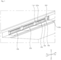
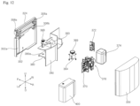
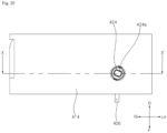
- the air-processing apparatus 100 includes a case 102, which defines the external appearance of the air-processing apparatus 100 and has an inlet 102a formed in one side thereof, a filter 188, which is disposed in the inlet 102a, a guide rail 10, which is disposed on the case 102 at a position above the inlet 102a, and a filter cleaner 300, which moves along the guide rail 10 to remove foreign substances from the filter 188.
- the case 102 includes a rear cover 114, in which the inlet 102a is formed, and a lower cover 106, which is disposed perpendicular to the rear cover 114 and in which an outlet 102b is formed.
- the case 102 may further include an upper cover (not shown), which is disposed above the lower cover 106 so as to be spaced apart therefrom, and a front cover (not shown), which is disposed in front of the rear cover 114 so as to be spaced apart therefrom.
- the inlet is formed in the rear cover 114 in a leftward-rightward direction.
- the filter 188 is disposed in the rear cover 114 in the leftward-rightward direction, in which the inlet 102a is formed.
- the inlet 102a is formed in the case 102 so as to be open in a rearward direction, which is perpendicular to a downward direction toward the floor, and the outlet 102b is formed in the case 102 at a position ahead of the inlet 102a so as to be open in the downward direction.
- the guide rail 10, along which the filter cleaner 300 moves, is mounted on the rear cover 114.
- the rear cover 114 is provided with a rail-fixing protrusion 117 for fixing one side of the guide rail 10.
- the rail-fixing protrusion 117 protrudes from the rear cover 114 in the rearward direction.
- the filter cleaner 300 moves along the rear cover 114 of the air-processing apparatus 100.
- the guide rail 10 for guiding the movement of the filter cleaner 300 is disposed on the rear cover 114.
- a support rail 116 for supporting the movement of the filter cleaner 300 is disposed at the upper end of the rear cover 114.
- the guide rail 10 may be formed integrally with the rear cover 114.
- the support rail 116 includes a top plate 116a, which protrudes rearwards from the upper end of the rear cover 114, and a bent portion 116b, which is bent and extends downwards from the rear end of the top plate 116a.
- a support roller 326 of the filter cleaner 300 which will be described later, may be disposed so as to be in contact with the inner surface of the bent portion 116b.
- the guide rail 10 is disposed on the rear side of the rear cover 114.
- the guide rail 10 is disposed above the inlet 102a in the rear cover 114.
- the guide rail 10 has a structure that extends in the leftward-rightward direction on the rear side of the rear cover 114.
- the guide rail 10 may be fixedly disposed below the rail-fixing protrusion 117.
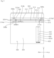
- the guide rail 10 includes a gear rail 20, which has threads to be engaged with a moving gear 358 of the filter cleaner 300, and a roller rail 22, which is in contact with guide rollers 308a and 308b of the filter cleaner 300.
- the roller rail 22 is disposed at each of the upper and lower ends of the rear surface 14 of the guide rail 10.
- the roller rail 22 is disposed behind the gear rail 20.
- the roller rail 22 is disposed at each of the upper side and the lower side of the guide rail 10.
- the roller rail 22 may have a rib structure that protrudes from the rear end of the guide rail 10 in the upward-downward direction.
- the roller rail 22 is formed so as to protrude downwards further than the threads of the gear rail 20.
- the gear rail 20 is disposed in front of the roller rail 22.
- the gear rail 20 is formed on the lower surface of the guide rail 10.
- the gear rail 20 may have the shape of a rack gear.
- the moving gear 358, which is engaged with the gear rail 20, may have the shape of a pinion gear.
- the guide rail 10 When viewed from the rear, the guide rail 10 may have a structure in which the gear rail 20 is shielded by the roller rail 22.
- the front surface 12 of the guide rail 10, which faces the rear cover 114, and the upper surface 16 of the guide rail 10, which faces the rail-fixing protrusion 117, may be in contact with the rear cover 114.
- a rail groove 24 is formed in the rear surface 14 of the guide rail 10.
- the rail groove 24 has a shape that is recessed in the forward direction, and extends in the leftward-rightward direction.
- An object to be sensed 26 is disposed in the rail groove 24. Referring to FIG. 6 , the object to be sensed may be provided in a plural number, and the plurality of objects to be sensed may be disposed so as to be spaced apart from each other in the leftward-rightward direction.
- a position detection sensor 322 may be disposed at the filter cleaner 300, and when the position detection sensor 322 senses the object to be sensed 26, the position of the filter cleaner 300 may be detected.
- the object to be sensed 26 may be formed in a structure corresponding to the position detection sensor 322.
- the position detection sensor 322 is a switch sensor
- the object to be sensed 26 may have the shape of a protrusion that protrudes rearwards.
- the position detection sensor 322 is a Hall sensor
- the object to be sensed 26 may be implemented as a magnet.
- an end plate 28 for limiting the movement of the filter cleaner 300 in one direction is disposed at the left end or the right end of the guide rail 10.
- the end plate 28 is disposed in a direction perpendicular to the direction in which the guide rail 10 extends.
- the end plate 28 protrudes rearwards from the rear cover 114.
- the end plate 28 is provided with a charging terminal 30, with which a connection terminal 320 of the filter cleaner 300 is brought into contact.
- the charging terminal 30 protrudes from the end plate 28 in the direction in which the guide rail 10 extends. Accordingly, when the filter cleaner 300 reaches the end plate 28, the connection terminal 320 of the filter cleaner 300 may be brought into contact with and connected to the charging terminal 30.
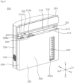
- the filter cleaner 300 is disposed at the rear side of the air-processing apparatus 100 so as to be movable in the leftward-rightward direction.
- the filter cleaner 300 moves in the leftward-rightward direction along the guide rail 10 disposed on the rear cover 114.
- the filter cleaner 300 may remove foreign substances adhered to the pre-filter 188.
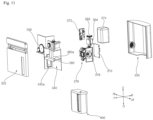
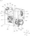
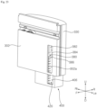
- the filter cleaner 300 includes housings 302 and 330, which define the external appearance of the filter cleaner 300, a moving gear 358, which is rotatably disposed inside the housings 302 and 330 in order to move the housings 302 and 330, a gear motor 356, which is disposed inside the housings 302 and 330 in order to rotate the moving gear 358, guide rollers 308a and 308b, which are rotatably disposed inside the housings 302 and 330 in order to guide the movement of the housings 302 and 330, a dust container 400, which receives foreign substances removed from the pre-filter 188, and a suction device 376, which forms the flow of air to the dust container 400.
- a moving gear 358 which is rotatably disposed inside the housings 302 and 330 in order to move the housings 302 and 330
- a gear motor 356 which is disposed inside the housings 302 and 330 in order to rotate the moving gear 358
- guide rollers 308a and 308b
- the dust container 400 includes a dust container housing 402 and an agitator 420 (refer to FIG. 19 ), which removes foreign substances from the pre-filter 188 by contacting the same.
- the concrete configuration of the dust container 400 will be described in detail later.
- the filter cleaner 300 includes a partition wall 340, which is disposed inside the housings 302 and 330 in order to partition the inner space in the housings 302 and 330, and a dust container guide 380, which is movably disposed on the partition wall 340 in order to displace the dust container 400.
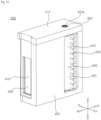
- the housings 302 and 330 define the external appearance of the filter cleaner 300.
- the housings 302 and 330 include a first housing 302, which is disposed so as to face the rear cover 114 when the filter cleaner 300 is mounted to the guide rail 10, and a second housing 330, which is disposed at the rear side of the first housing 302 in order to cover the same.
- the housings 302 and 330 have a dust container hole 301 formed in the lower surfaces thereof to allow the dust container 400 to be withdrawn therefrom or inserted thereinto.
- the first housing 302 may have the shape of a plate that is parallel to the pre-filter 188. When the filter cleaner 300 moves in the region behind the pre-filter 188, the first housing 302 may be maintained at a constant interval behind the pre-filter 188.
- the first housing 302 includes a base plate 304, which has the shape of a plate that is parallel to the pre-filter 188, and a guide groove 310, which is formed in the base plate 304 so as to be recessed rearwards in order to provide a space in which the guide rail 10 is disposed.
- the base plate 304 has a suction hole 302a formed therein to introduce foreign substances into the dust container 400 therethrough.
- the agitator 420 is disposed at a position corresponding to the suction hole 302a.
- the suction hole 302a may be formed to have a size corresponding to that of the pre-filter 188 disposed on the rear cover 114. That is, the height of the suction hole 302a in the upward-downward direction may be set to correspond to the height of the pre-filter 188 in the upward-downward direction.
- the first housing 302 includes a peripheral wall 306, which extends rearwards from the periphery of the base plate 304, and a top wall 324, which is bent and extends rearwards from the upper end of the base plate 304.
- the top wall 324 is disposed so as to be spaced upwards apart from the peripheral wall 306.
- a support roller 326 which is in contact with the support rail 116 of the rear cover 114, is disposed on the top wall 324.
- the support roller 326 rotates about a rotation axis 326RS extending in the upward-downward direction.
- the rotation axis 326RS of the support roller 326 extends perpendicular to the rotation axes 308aRS and 308bRS of the guide rollers 308a and 308b.
- the rotation axis 326RS of the support roller 326 extends perpendicular to the rotation axis 358RS of the moving gear 358.
- the support roller 326 may be in contact with the bent portion 116b of the support rail 116, thereby supporting displacement of the filter cleaner 300.
- the guide groove 310 may be defined by an upper wall 312, a lower wall 314, and an inner wall 316.
- the upper wall 312 covers the upper portion of the guide groove 310.
- the upper wall 312 has therein upper roller holes 312a1 and 312a2, through which portions of the guide rollers 308a pass.
- two upper roller holes 312a1 and 312a2 may be disposed in the upper wall 312 so as to be spaced apart from each other in the leftward-rightward direction.
- the upper roller holes 312a1 and 312a2 include a first upper roller hole 312a1 and a second upper roller hole 312a2, which is spaced apart from the first upper roller hole 312a1 in the leftward-rightward direction.
- the first upper roller hole 312a1 is disposed above a lower roller hole 314a
- the second upper roller hole 312a2 is disposed above a support protrusion 315.
- the lower wall 314 covers the lower portion of the guide groove 310.
- the lower wall 314 has therein a lower roller hole 314a, through which a portion of the guide roller 308b passes, and a gear hole 314b, through which a portion of the moving gear 358 passes.
- the lower wall 314 is provided with a support protrusion 315 protruding upwards toward the guide rail.
- the support protrusion 315 is spaced apart from the lower roller hole 314a in the leftward-rightward direction.
- the support protrusion 315 may be disposed above the dust container 400.
- the gear hole 314b is formed between the support protrusion 315 and the lower roller hole 314a.
- the height 315H by which the support protrusion 315 protrudes upwards from the lower wall 314 is set to be lower than the height 308bH by which the guide roller 308b protrudes from the lower wall 314.
- the inner wall 316 interconnects the rear end of the lower wall 314 and the rear end of the upper wall 312.
- the inner wall 316 is provided with a protruding portion 318 protruding forwards.
- the protruding portion 318 extends in the leftward-rightward direction along the inner wall 316.
- the position detection sensor 322 is disposed on the protruding portion 318 in order to detect the position of the filter cleaner 300.
- the position detection sensor 322 may be implemented as a switch sensor or a Hall sensor.
- the position detection sensor 322 may react with the object to be sensed 26 disposed on the guide rail 10, thereby detecting the position of the filter cleaner 300.
- connection terminal 320 protrudes from one lateral end of the protruding portion 318.
- the connection terminal 320 protrudes toward the end plate 28.
- power may be supplied to a battery 374 disposed inside the housings 302 and 330.
- the guide rollers 308a and 308b are disposed in the first housing 302 so as to rotate in contact with the roller rail 22 of the guide rail 10 and to guide the movement of the filter cleaner 300.
- the guide rollers 308a and 308b are disposed in the guide groove 310 in the upward-downward direction.
- the guide rollers 308a and 308b are disposed such that portions thereof protrude into the guide groove 310.
- the guide rollers 308a and 308b are disposed inside the first housing 302.
- the guide rollers 308a and 308b may include upper rollers 308a disposed at the upper side of the guide groove 310 and a lower roller 308b disposed at the lower side of the guide groove 310.
- each of the guide rollers 308a and 308b has a groove 309 formed concavely in the circumferential surface thereof in the circumferential direction.
- the roller rail 22 of the guide rail 10 may be inserted into the groove 309 formed in each of the guide rollers 308a and 308b. Since the roller rail 22 is inserted into the guide rollers 308a and 308b, the filter cleaner 300 may move stably.
- the filter cleaner 300 includes two upper rollers 308a and one lower roller 308b.
- the two upper rollers 308a are spaced apart from each other in the leftward-rightward direction.
- One of the two upper rollers 308a is disposed above the lower roller 308b.
- the support protrusion 315 may be disposed below the other one of the two upper rollers 308a.
- the rotation axes 308aRS and 308bRS of the guide rollers 308a and 308b extend perpendicular to the rotation axis 326RS of the support roller 326.
- the moving gear 358 is rotatably disposed at the lower side of the guide groove 310. A portion of the moving gear 358 is disposed in the guide groove 310 through the gear hole 314b formed in the lower wall 314.
- the moving gear 358 may be rotatably mounted in the first housing 302 or to the partition wall 340 to be described later.
- the moving gear 358 is disposed at a position further forward than the guide rollers 308a and 308b.
- the rotation axis of the moving gear 358 extends parallel to the rotation axes of the guide rollers 308a and 308b.
- a space in which an agitator gear 366 and an agitator connection shaft 368, which will be described later, are rotatably disposed is formed in the inner surface of the first housing 302.
- the partition wall 340 is disposed between the first housing 302 and the second housing 330.
- the partition wall 340 may include a plurality of partition plates to partition the interior of the housings 302 and 330.
- the partition wall 340 may be disposed inside the housings 302 and 330 to increase the rigidity of the housings 302 and 330.
- the partition wall 340 forms a space in which the dust container 400 is disposed.
- a dust container guide 380 for guiding the movement of the dust container 400 is disposed on the partition wall 340.
- the dust container guide 380 may be displaced in the upward-downward direction by a dust container gear and a dust container motor 360, which are disposed on the partition wall 340.
- the partition wall 340 may isolate the space in which the dust container 400 is disposed from the space in which the suction device 376 is disposed.
- the partition wall 340 may isolate the space in which the dust container 400 is disposed from the space in which the dust container gear 362 for displacing the dust container 400 is disposed.
- the partition wall 340 may isolate the space in which the dust container 400 is disposed from the space in which a first printed circuit board 370 is disposed.
- the partition wall 340 may isolate the space in which the battery 374 is disposed from the space in which the suction device 376 is disposed.
- the partition wall 340 may isolate the space in which the battery 374 is disposed from the space in which the moving gear 358 is disposed.
- the partition wall 340 may isolate the space in which the dust container motor 360 is disposed from the space in which the agitator motor 364 is disposed.
- the partition wall 340 may partition the inner space in the housings 302 and 330 into a plurality of regions using a plurality of plates arranged perpendicular to or parallel to each other.
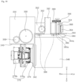
- the partition wall 340 includes a vertical partition 342, which partitions the interior of the housings 302 and 330 in the leftward-rightward direction, horizontal partitions 344 and 346, which partition the interior of the housings 302 and 330 in the upward-downward direction, and forward-rearward partitions 348 and 350, which partition the interior of the housings 302 and 330 in the forward-rearward direction.
- the vertical partition 342 isolates the space in which the suctioner 376 is disposed from the space in which the dust container 400 is disposed.
- the vertical partition 342 extends in the upward-downward direction inside the housings 302 and 330.
- the vertical partition 342 isolates the space in which the battery 374 is disposed from the space in which the dust container 400 is disposed.
- the vertical partition 342 isolates the space in which the battery 374 is disposed from the space in which the dust container gear 362 and the agitator gear 366 are disposed.
- the battery 374 is disposed above the suction device 376.
- the vertical partition 342 has therein a communication hole 342a formed at a portion corresponding to the suctioner 376, through which the suction device 376 and the dust container 400 communicate with each other.
- the horizontal partitions 344 and 346 include a first horizontal partition 344, which isolates the space in which the dust container 400 is disposed from the space in which the dust container gear 362 and the agitator gear 366 are disposed, and a second horizontal partition 346, which isolates the space in which the suction device 376 is disposed from the space in which the battery 374 is disposed.
- the first horizontal partition 344 has a shaft hole 344b formed therein to allow the agitator connection shaft 368 to pass therethrough.
- the first horizontal partition 344 has a guide hole 344a formed therein to allow some components of the dust container guide 380 to pass therethrough.
- the forward-rearward partitions 348 and 350 include a first forward-rearward partition 348, which isolates the space in which the dust container 400 is disposed from the space in which the first printed circuit board 370 is disposed, and a second forward-rearward partition 350, which isolates the space in which the battery 374 is disposed from the space in which the moving gear 358 is disposed.
- the partition wall 340 includes a first support plate 352, which is disposed on the first horizontal partition 344 to support placement of the dust container motor 360, and a second support plate 354, which is disposed above the first horizontal partition 344 to support placement of the agitator gear 366 and the agitator connection shaft 368.
- the dust container 400 is disposed below the first horizontal partition 344.
- the dust container 400 is disposed on one side of the vertical partition 342.
- the dust container guide 380 is disposed above the dust container 400.
- the dust container guide 380 may be connected to the dust container gear 362 to displace the dust container 400.
- the dust container guide 380 includes a guide plate 384, which is disposed above the dust container 400, and a guide gear 382, which extends upwards from the guide plate 384 and is engaged with the dust container gear 362.
- the guide plate 384 is disposed below the first horizontal partition 344.
- a magnet 388 may be disposed on the guide plate 384. Accordingly, when the dust container 400 is brought into contact with the magnet 388, the dust container 400 may be secured to the dust container guide 380 by the magnet 388.
- the dust container guide 380 includes mounting guides 386, which are bent and extend downwards from the front end and the rear end of the guide plate 384.
- the mounting guides 386 may guide the dust container 400 to move to the correct position on the guide plate 384.
- the guide plate 384 has a connection hole 380a formed therein to allow the agitator connection shaft 368 to pass therethrough.
- the connection hole 380a is formed at a position corresponding to the shaft hole 344b formed in the first horizontal partition 344.
- the guide gear 382 is disposed through the guide hole 344a formed in the first horizontal partition 344.
- the guide gear 382 may be implemented as a rack gear.
- the guide gear 382 meshes with the dust container gear 362.
- the guide gear 382 may move in the upward-downward direction in response to rotation of the dust container gear 362. Accordingly, when the dust container motor 360 operates, the dust container guide 380 may move in the upward-downward direction.
- the dust container motor 360 is disposed above the first horizontal partition 344, and is mounted to the first support plate 352.
- the first printed circuit board 370 is disposed on the rear surface of the first forward-rearward partition 348.
- the suction device 376 is disposed below the second horizontal partition 346.
- the suction device 376 is disposed on the opposite side of the vertical partition 342.
- the suction device 376 may include a fan 376a, which causes air to flow, and a fan motor 376b, which rotates the fan 376a.
- a connection pipe 378 for connecting the suction device 376 to the vertical partition 342 may be disposed at one side of the suctioner 376.
- the connection pipe 378 is fixed to the portion of the vertical partition 342 in which the communication hole 342a is formed, thereby inducing air to flow from the dust container 400 to the suction device 376.
- the battery 374 may be disposed above the second horizontal partition 346.
- the battery 374 may be disposed above the suction device 376.
- a second printed circuit board 372 and a gear motor 356 for rotating the moving gear 358 are disposed in the space in which the battery 374 is disposed.
- the second printed circuit board 372 and the moving gear 358 are mounted to the second forward-rearward partition 350.
- the moving gear 358 and a connection gear 359, which meshes with the moving gear 358 and which is connected to the gear motor 356, are disposed in front of the second forward-rearward partition 350.
- the moving gear 358 may have a larger radius than the connection gear 359.
- the agitator motor 364 and the agitator gear 366 are disposed above the first horizontal partition 344.
- the second support plate 354 is spaced upwards apart from the first horizontal partition 344.
- the second support plate 354 is disposed parallel to the first horizontal partition 344.
- the agitator motor 364 is disposed below the second support plate 354.
- the agitator gear 366 and an auxiliary gear 369, which is connected to the agitator motor 364 and which meshes with the agitator gear 366, are disposed above the second support plate 354.
- the agitator gear 366 is fixedly disposed on the circumference of the agitator connection shaft 368. Accordingly, when the agitator gear 366 rotates, the agitator connection shaft 368 also rotates together therewith.
- the agitator connection shaft 368 is disposed so as to penetrate the second horizontal partition 346.
- the agitator connection shaft 368 may have a circular-shaped section. However, the lower end of the agitator connection shaft 368 may have an elliptical-shaped or polygonal-shaped section in order to transmit rotational force to the agitator 420.
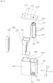
- the dust container 400 includes a storage space 402a, in which foreign substances removed from the pre-filter 188 are stored, a dust container housing 402, which forms an agitator space 402b in which the agitator 420 is disposed, a dust container cover 414, which covers an open side of the dust container housing 402, an agitator 420, which is rotatably disposed inside the dust container housing 402, and a dust container filter 428, which is disposed at one side of the dust container housing 402 in order to remove foreign substances from the air discharged from the dust container housing 402.
- the agitator space 402b in which the agitator 420 is disposed and the storage space 402a in which dust is stored are formed inside the dust container housing 402.
- the dust container housing 402 has an open upper portion. Accordingly, the agitator 420 or the dust container filter 428 may be withdrawn out of the dust container housing 403 through the open upper portion of the dust container housing 403.
- the dust container housing 402 has an agitator hole 406 formed therein to allow the agitator space 402b to communicate with the outside. A portion of the agitator 420 may be exposed to the outside of the dust container housing 402 through the agitator hole 406.
- the agitator hole 406 may be formed to have a size corresponding to the size of the suction hole 302a in the first housing 302.
- the dust container housing 402 has a flow hole 410 formed therein to allow the air in the storage space 402a to flow to the outside of the dust container housing 402.
- the flow hole 410 is formed in the lateral surface of the dust container housing 402.
- the flow hole 410 is formed to have a size corresponding to the size of the communication hole 342a in the vertical partition 342.
- the flow hole 410 is disposed at a position corresponding to the communication hole 342a.
- an inner partition 404 for isolating the storage space 402a and the agitator space 402b from each other is disposed in the dust container housing 402.
- the inner partition 404 is formed so as to extend in the upward-downward direction.
- the inner partition 404 has an inner hole 408 formed therein to allow the storage space 402a and the agitator space 402b to communicate with each other.
- a duster 412 is disposed in the agitator space 402b so as to be in contact with an end portion of the agitator 420.
- the duster 412 may remove foreign substances from a blade 426 of the agitator 420, which will be described later.
- the duster 412 may be disposed so as to rub the blade 426 when the agitator 420 rotates.
- the duster 412 may be disposed so as to protrude toward the agitator 420.
- the duster 412 has a sawtooth shape, and is disposed on one side of the inner hole 408.
- the duster 412 protrudes so as to contact the blade 426. Accordingly, when the agitator 420 operates, the duster 412 may remove foreign substances from the blade 426 of the agitator 420. Also, when the dust container 400 is removed from the filter cleaner 300, the duster 412 may prevent the foreign substances stored in the storage space 402a from escaping to the outside through the agitator space 402b.
- an agitator-mounting part 405, to which the agitator 420 is mounted is disposed in the dust container housing 402.
- the agitator-mounting part 405 may be disposed at the lower portion of the agitator space 402b, and the lower end portion of the agitator 420 may be seated on the agitator-mounting part 405.
- the dust container cover 414 covers the open upper portion of the dust container housing 402.
- the dust container cover 414 has therein a through-hole 416, through which the lower portion of the agitator connection shaft 368 passes.
- the through-hole 416 is formed at a position corresponding to the connection hole 380a formed in the guide plate 384 of the dust container guide 380. Accordingly, when the dust container 400 is mounted to the dust container guide 380, the connection hole 380a and the through-hole 416 may be located so as to be aligned with each other.
- a counterpart member 418 which responds to the magnet 388 disposed on the guide plate 384, may be disposed on the dust container cover 414.
- the counterpart member 418 may be made of a material that is attracted to the magnet 388. Accordingly, when the dust container 400 is brought close to the dust container guide 380, the dust container 400 may be secured to the dust container guide 380 due to the magnet 388 and the counterpart member 418.
- the agitator 420 is rotatably mounted to the dust container housing 402.
- the agitator 420 may rotate about a rotation axis extending in the upward-downward direction.
- the agitator 420 may be disposed so as to be in contact with the outer side of the pre-filter.
- the agitator 420 may shake foreign substances off the pre-filter 188.
- the agitator 420 includes a rotating body 422, which rotates about a rotation axis extending in the upward-downward direction, a plurality of blades 426, which protrude from the outer circumferential surface of the rotating body 422 in the radial direction, and a connection body 424, which is disposed at one end of the rotating body 422 and which is connected to the agitator connection shaft 368.
- the agitator 420 further includes a mounting body 425, which is rotatably connected to the rotating body 422.
- the mounting body 425 is mounted to the agitator-mounting part 405 of the dust container housing 402 in order to fix the agitator 420 in place. Since the mounting body 425 is rotatably connected to the rotating body 422, the agitator 420 may rotate stably in the state of being fixed to the agitator-mounting part 405.
- connection body 424 is disposed at the upper side of the rotating body 422.
- the connection body 424 has a connection recess 424a formed in the upper surface thereof to allow the lower end of the agitator connection shaft 368 to be inserted thereinto.
- the connection recess 424a may have a shape corresponding to the shape of the lower end of the agitator connection shaft 368. Accordingly, when the agitator connection shaft 368 is inserted into the connection recess 424a in the connection body 424, the agitator connection shaft 368 and the agitator 420 may rotate together.
- the dust container filter 428 is disposed in the storage space 402a in the dust container housing 402.
- the dust container filter 428 includes a first filter 430, which is disposed on one side of the flow hole 410 in the dust container housing 402 to remove fine foreign substances from the air flowing to the flow hole 410, a second filter 432, which is disposed in the storage space 402a while being spaced apart from the first filter 430, and a mounting body 434, which fixes the second filter 432 in place.
- the mounting body 434 has a structure that is capable of being mounted in the storage space 402a.
- the mounting body 434 includes a lower plate 436, which is disposed in the lower side of the storage space 402a, an upper plate 438, which is disposed so as to be spaced upwards apart from the lower plate 436, and a connection plate 440, which interconnects the lower plate 436 and the upper plate 438 and supports the second filter 432, which is disposed on one side thereof.
- the lower plate 436 is fixed to the lower portion of the storage space 402a.
- the upper plate 438 is fixed to the upper portion of the storage space 402a. Accordingly, when the dust container filter 428 is disposed in the storage space 402a, the position of the dust container filter 428 inside the storage space 402a may be maintained.
- the second filter 432 may be fixedly disposed on the mounting body 434. That is, the second filter 432 may be formed integrally with the connection plate 440.
- connection plate 440 may be disposed so as to be inclined relative to the first filter 430.
- the second filter 432 may be spaced apart from the first filter 430, and may be inclined relative to the first filter 430.
- the first filter 430 may be implemented as a high-efficiency particulate air (HEPA) filter to remove fine foreign substances.
- the second filter 432 may implemented as a filter that removes foreign substances having a size larger than the size of foreign substances removed by the first filter 430.
- the second filter 432 may be implemented as a filter that is capable of being washed for reuse.
- the first filter 430 may be mounted in the mounting body 434.
- the first filter 430 may be disposed between the upper plate 438 and the lower plate 436 of the mounting body 434.
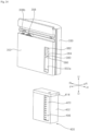
- the filter cleaner 300 is maintained in the state in which the same is mounted on the guide rail 10. Therefore, it may be difficult for a user to reach the filter cleaner 300 mounted in the ceiling-mounted air-processing apparatus 100.
- the dust container 400 since the dust container 400 is capable of being moved downwards by the dust container guide 380, the user may easily reach the same.
- the dust container 400 may be moved in the upward-downward direction by the dust container guide 380.
- the dust container guide 380 may be moved in the upward-downward direction by the operation of the dust container gear 362.
- the dust container 400 may be securely disposed on the dust container guide 380 by the magnet 388 of the dust container guide 380.
- the magnet 388 of the dust container guide 380 attracts the counterpart member 418 of the dust container 400, so the dust container 400 may be secured to the dust container guide 380.
- the dust container 400 may be located at a first position P1, at which the same is located inside the housings 302 and 330, or a second position P2, at which a portion of the dust container 400 is located outside the housings 302 and 330.
- the agitator 420 is connected to the agitator connection shaft 368. Accordingly, when the dust container 400 is located at the first position P1, the agitator 420 may be rotated by the operation of the agitator motor 364.
- the agitator 420 is separated from the agitator connection shaft 368. Accordingly, when the dust container 400 is located at the second position P2, the agitator 420 is not rotated even when the agitator motor 364 operates.
- the user is capable of separating the dust container 400 from the filter cleaner 300, as shown in FIG. 24 .
- the air-processing apparatus of the present disclosure has one or more effects as follows.
- the agitator is disposed inside the dust container, and the dust container is mounted in the housing of the filter cleaner. Accordingly, the dust container and the agitator, in which foreign substances may be present, are capable of being managed together, whereby it is possible to maintain the cleanliness of the filter cleaner.
- the dust container is capable of being moved downwards from the filter cleaner by the dust container guide, a user is capable of easily separating and replacing the dust container even when the filter cleaner is used in a product that is mounted on a ceiling.
- the agitator is disposed inside the dust container, the region in which foreign substances are stored communicates with the outside via the agitator region. Due to this structure, when the dust container is separated, it is possible to minimize the amount of foreign substances that escape from the dust container to the outside.
- the filter cleaner is capable of moving stably along the guide rail due to the guide rollers provided so as to move along the guide rail and the support roller disposed on the guide rail. Further, since the rotation axis of the support roller extends in a direction different from that in which the rotation axes of the guide rollers extend, it is possible to maintain a constant gap between the filter and the filter cleaner below the guide rail.
- the filter cleaner includes therein a battery, and when the filter cleaner is located in a non-cleaning section, the battery is charged by receiving external power through terminals. As such, since the filter cleaner does not require an electric wire for connection to an external power source, the filter cleaner is capable of moving freely.
Landscapes
- Engineering & Computer Science (AREA)
- Chemical & Material Sciences (AREA)
- Combustion & Propulsion (AREA)
- Mechanical Engineering (AREA)
- General Engineering & Computer Science (AREA)
- Chemical Kinetics & Catalysis (AREA)
- Filtering Of Dispersed Particles In Gases (AREA)
Claims (14)
- Ein Filterreiniger (300), der aufweist:ein Gehäuse (302, 330), das die äußere Erscheinung des Filterreinigers (300) bildet, wobei das Gehäuse (302, 330) eine Ansaugöffnung (302a), die in einer Seite davon ausgebildet ist, und eine Auslassöffnung aufweist, die in einer anderen Seite davon ausgebildet ist;ein Bewegungszahnrad (358), das drehbar in dem Gehäuse (302, 330) angeordnet ist, um das Gehäuse (302, 330) zu bewegen;einen Getriebemotor (356), der konfiguriert ist, das Bewegungszahnrad (358) zu drehen; einen Staubbehälter (400), der so angeordnet ist, dass er in das Gehäuse (302, 330) eingeführt oder aus diesem herausgezogen werden kann, wobei der Staubbehälter (400) konfiguriert ist, Fremdstoffe zu speichern, die durch die Ansaugöffnung (302a) in ihn eingeführt werden, wobei der Staubbehälter (400) ein Staubbehältergehäuse (402), in dem ein Speicherraum (402a) ausgebildet ist, in dem von einem Filter (188) entfernte Fremdstoffe gespeichert werden, einen Rührwerksraum (402b) und ein Rührwerk (420) aufweist, der drehbar im Rührwerksraum (402b) angeordnet und konfiguriert ist, Fremdstoffe vom Filter (188) zu entfernen, indem es diesen berührt;ein Rührwerkszahnrad (366), das innerhalb des Gehäuses (302, 330) angeordnet ist, um das Rührwerk (420) zu drehen;eine Rührwerksverbindungswelle (368), die konfiguriert ist, eine Drehkraft des Rührwerkszahnrads (366) auf das Rührwerk (420) zu übertragen;einen Rührwerksmotor (364), der innerhalb des Gehäuses (302, 330) angeordnet ist, um das Rührwerkszahnrad (366) zu betreiben; undeine Ansaugvorrichtung (376), die innerhalb des Gehäuses (302, 330) angeordnet ist, um zu bewirken, dass Luft in den Staubbehälter (400) durch die Ansaugöffnung (302a) strömt, wenn der Staubbehälter (400) im Gehäuse (302, 330) angebracht ist,wobei das Rührwerkszahnrad (366) fest an einem Umfang der Rührwerksverbindungswelle (368) angeordnet ist, so dass es sich zusammen mit der Rührwerksverbindungswelle (368) dreht,wobei das Rührwerk (420) eine darin ausgebildete Verbindungsaussparung (424a) aufweist, um es zu ermöglichen, dass die Rührwerksverbindungswelle (368) darin eingesetzt wird, undwobei, wenn der Staubbehälter (400) im Gehäuse (302, 330) angebracht ist, die Rührwerksverbindungswelle (368) in der Verbindungsaussparung (424a) eingesetzt ist.
- Filterreiniger (300) nach Anspruch 1,wobei das Staubbehältergehäuse (402) eine darin ausgebildete Rührwerksöffnung (406) aufweist, um es zu ermöglichen, dass der Rührwerksraum (402b) mit dem Äußeren in Verbindung steht, undwobei, wenn der Staubbehälter (400) in dem Gehäuse (302, 330) angebracht ist, die Rührwerksöffnung (406) an einer Position angeordnet ist, die der Ansaugöffnung (302a) entspricht.
- Filterreiniger (300) nach Anspruch 2, wobei das Staubbehältergehäuse (402) eine darin ausgebildete Durchflussöffnung (410) aufweist, um es zu ermöglichen, dass der Speicherraum (402a) mit einem Äußeren des Staubbehältergehäuses (402) in Verbindung steht,wobei der Staubbehälter (400) einen Staubbehälterfilter (428) aufweist, der im Speicherraum (402a) angeordnet ist, um Fremdstoffe aus der zur Durchflussöffnung (410) strömenden Luft zu entfernen, undwobei, wenn der Staubbehälter (400) in dem Gehäuse (302, 330) angebracht ist, die Saugvorrichtung (376) mit der Durchflussöffnung (410) in Verbindung steht.
- Filterreiniger (300) nach Anspruch 3, wobei der Staubbehälterfilter (428) aufweist:einen ersten Filter (430), der auf einer Seite der Durchflussöffnung (410) im Staubbehältergehäuse (402) angeordnet ist;einen zweiten Filter (432), der so angeordnet ist, dass er vom ersten Filter (430) beabstandet ist; undeinen Befestigungskörper (434), der konfiguriert ist, Positionen des ersten Filters (430) und des zweiten Filters (432) zu fixieren, die innerhalb des Staubbehältergehäuses (402) angeordnet sind.
- Filterreiniger (300) nach Anspruch 4, wobei der Befestigungskörper (434) aufweist:eine untere Platte (436), die an einer Unterseite des Speicherraums (402a) angeordnet ist;eine obere Platte (438), die so angeordnet ist, dass sie nach oben von der unteren Platte (436) beabstandet ist; undeine Verbindungsplatte (440), die konfiguriert ist, die untere Platte (436) und die obere Platte (438) miteinander zu verbinden und den zweiten Filter (432) zu halten, der auf einer Seite davon angeordnet ist.
- Filterreiniger (300) nach Anspruch 5, wobei der zweite Filter (432) eine Maschenform aufweist und integral mit der Verbindungsplatte (440) ausgebildet ist.
- Filterreiniger (300) nach Anspruch 5 oder 6, wobei die Verbindungsplatte (440), auf der der zweite Filter (432) angeordnet ist, relativ zum ersten Filter (430) geneigt ist, wobei der erste Filter (430) fest zwischen der unteren Platte (436) und der oberen Platte (438) angeordnet ist.
- Filterreiniger (300) nach einem der Ansprüche 2 bis 7, wobei der Staubbehälter (400) eine innere Trennwand (404) aufweist, die konfiguriert ist, den Speicherraum (402a) und den Rührwerksraum (402b) innerhalb des Staubbehältergehäuses (402) voneinander zu isolieren, und
wobei die innere Trennwand (404) eine darin ausgebildete innere Öffnung (408) aufweist, um zu ermöglichen, dass der Speicherraum (402a) und der Rührwerksraum (402b) miteinander in Verbindung stehen. - Filterreiniger (300) nach einem der Ansprüche 2 bis 8, wobei ein Staubtuch (412) im Rührwerksraum (402b) so angeordnet ist, dass es mit einem Endabschnitt des Rührwerks (420) in Kontakt steht.
- Filterreiniger (300) nach einem der vorhergehenden Ansprüche, wobei die Rührwerksverbindungswelle (368) einen mit dem Rührwerk (420) verbundenen Endabschnitt aufweist, wobei der Endabschnitt der Rührwerksverbindungswelle (368) einen elliptisch oder polygonal geformten Querschnitt aufweist, und
wobei die Verbindungsaussparung (424a) eine Form hat, die dem Endabschnitt des Rührwerks (420) entspricht. - Filterreiniger (300) nach einem der vorhergehenden Ansprüche, wobei der Staubbehälter (400) eine Staubbehälterführung (380) aufweist, die konfiguriert ist, den im Gehäuse (302, 330) angeordneten Staubbehälter (400) zu verschieben, und
wobei die Staubbehälterführung (380) eine darin ausgebildete Verbindungsöffnung (380a) aufweist, um es zu ermöglichen, dass die Rührwerksverbindungswelle (368) dort hindurchgeht. - Filterreiniger (300) nach Anspruch 11, wobei die Staubbehälterführung (380) aufweist:eine Führungsplatte (384), die über dem Staubbehälter (400) angeordnet ist; undein Führungszahnrad (382), das sich von der Führungsplatte (384) nach oben erstreckt, wobei das Führungszahnrad (382) mit einem Staubbehälterzahnrad (362) in Eingriff steht, undwobei ein Magnet (388) an der Führungsplatte (384) angeordnet ist, um den Staubbehälter (400) zu befestigen.
- Filterreiniger (300) nach Anspruch 12, wobei die Staubbehälterführung (380) Befestigungsführungen (386) aufweist, um den Staubbehälter (400) in eine korrekte Position auf der Führungsplatte (384) zu führen, wenn sich der Staubbehälter (400) nach oben bewegt, und
wobei die Befestigungsführungen (386) gebogen sind und sich von einem vorderen Ende und einem hinteren Ende der Führungsplatte (384) nach unten erstrecken. - Filterreiniger (300) nach Anspruch 12 oder 13, der ferner aufweist:eine Trennwand (340), die innerhalb des Gehäuses (302, 330) angeordnet ist, um einen Innenraum in dem Gehäuse (302, 330) zu unterteilen,wobei die Staubbehälterführung (380) beweglich an der Trennwand (340) angeordnet ist, wobei die Trennwand (340) eine horizontale Trennwand (344, 346) aufweist, um den Innenraum im Gehäuse (302, 330) in einer vertikalen Richtung zu unterteilen,wobei das Staubbehälterzahnrad (362) über der horizontalen Trennwand (344, 346) angeordnet ist, um die Staubbehälterführung (380) zu bewegen, undwobei die Staubbehälterführung (380) unter der horizontalen Trennwand (344, 346) beweglich angeordnet ist.
Applications Claiming Priority (2)
| Application Number | Priority Date | Filing Date | Title |
|---|---|---|---|
| KR1020210065984A KR102534208B1 (ko) | 2021-05-24 | 2021-05-24 | 필터청소기와 이를 포함하는 공기처리장치 |
| KR1020210065985A KR102553491B1 (ko) | 2021-05-24 | 2021-05-24 | 공기처리장치 |
Publications (2)
| Publication Number | Publication Date |
|---|---|
| EP4095447A1 EP4095447A1 (de) | 2022-11-30 |
| EP4095447B1 true EP4095447B1 (de) | 2024-06-26 |
Family
ID=82019161
Family Applications (1)
| Application Number | Title | Priority Date | Filing Date |
|---|---|---|---|
| EP22173504.6A Active EP4095447B1 (de) | 2021-05-24 | 2022-05-16 | Filterreiniger-einheit |
Country Status (4)
| Country | Link |
|---|---|
| US (1) | US12134058B2 (de) |
| EP (1) | EP4095447B1 (de) |
| JP (1) | JP2022180329A (de) |
| CN (1) | CN115388472A (de) |
Families Citing this family (5)
| Publication number | Priority date | Publication date | Assignee | Title |
|---|---|---|---|---|
| US12480667B2 (en) * | 2021-05-24 | 2025-11-25 | Lg Electronics Inc. | Air-conditioning system |
| US12326277B2 (en) * | 2021-05-24 | 2025-06-10 | Lg Electronics Inc. | Air-conditioning system |
| US12474068B2 (en) * | 2021-05-24 | 2025-11-18 | Lg Electronics Inc. | Air-conditioning system |
| US12385666B2 (en) | 2021-05-24 | 2025-08-12 | Lg Electronics Inc. | Air-processing apparatus |
| CN117339319B (zh) * | 2023-10-12 | 2024-07-26 | 意朗智能科技(南通)有限公司 | 节能空压机用空气分级过滤干燥装置 |
Family Cites Families (109)
| Publication number | Priority date | Publication date | Assignee | Title |
|---|---|---|---|---|
| JPH06106967A (ja) | 1992-09-29 | 1994-04-19 | Nippon Plast Co Ltd | 車両用空調吹出装置 |
| JPH06147531A (ja) | 1992-11-10 | 1994-05-27 | Toshiba Corp | 空気調和装置の室内ユニット |
| JP2965120B2 (ja) | 1994-02-10 | 1999-10-18 | 株式会社富士通ゼネラル | 空気調和機 |
| JPH085091A (ja) | 1994-06-15 | 1996-01-12 | Shimizu Corp | 天井内埋込式の空気調和装置 |
| JP3519482B2 (ja) | 1995-02-20 | 2004-04-12 | 三菱電機株式会社 | 換気システム、及び、換気ユニット |
| JP3365135B2 (ja) | 1995-03-30 | 2003-01-08 | 三菱電機株式会社 | 空気調和装置 |
| US5595068A (en) | 1995-12-15 | 1997-01-21 | Carrier Corporation | Ceiling mounted indoor unit for an air conditioning system |
| KR100267549B1 (ko) | 1998-02-03 | 2000-10-16 | 구자홍 | 공기조화기의 공기 토출장치 |
| KR200164654Y1 (ko) | 1999-09-01 | 2000-02-15 | 대우전자주식회사 | 공기조화기 실내기의 토출구 개폐장치 |
| KR200184583Y1 (ko) | 1999-12-30 | 2000-06-01 | 주식회사일진엔지니어링 | 대용량 건식 제습공조기 |
| JP3861555B2 (ja) | 2000-03-24 | 2006-12-20 | 松下電器産業株式会社 | セパレート型空気調和機 |
| WO2002103248A2 (en) | 2001-06-19 | 2002-12-27 | Lg Electronics Inc. | Air conditioner |
| JP4688367B2 (ja) | 2001-08-24 | 2011-05-25 | 三洋電機株式会社 | 壁掛け型空気調和装置 |
| JP2003148763A (ja) | 2001-11-08 | 2003-05-21 | Sanyo Electric Co Ltd | 壁掛け型空気調和装置 |
| KR100432693B1 (ko) | 2001-12-24 | 2004-05-22 | 위니아만도 주식회사 | 에어컨 실내기의 프레임필터 승강장치 |
| JP4145106B2 (ja) | 2002-09-10 | 2008-09-03 | シャープ株式会社 | 空気調和機 |
| KR20040056151A (ko) | 2002-12-23 | 2004-06-30 | 삼성전자주식회사 | 공기청정기 |
| AU2003203151A1 (en) | 2003-02-07 | 2004-08-30 | A/S Ribe Jernindustri | Ventilating aggregate , units, system and methode including units that are easily connectable to other units and safety switch |
| KR101086607B1 (ko) | 2003-03-04 | 2011-11-23 | 파나소닉 주식회사 | 공기 필터의 자동 청소 기능부 실내 유닛을 구비한 공기 조화기 |
| FR2859522B1 (fr) | 2003-09-10 | 2006-10-27 | Airinspace Ltd | Procede et dispositif de ventilation et de decontamination aeroportee par un melange a flux de soufflage et aspiration attaches par effet coanda |
| JP2005172261A (ja) | 2003-12-08 | 2005-06-30 | Matsushita Electric Ind Co Ltd | 空気調和機の制御装置 |
| JP2005214429A (ja) | 2004-01-27 | 2005-08-11 | Hitachi Ltd | 室内ユニット |
| KR20050117665A (ko) | 2004-06-11 | 2005-12-15 | 엘지전자 주식회사 | 분리형 공기조화기의 실내기 |
| KR100546618B1 (ko) | 2004-06-24 | 2006-01-26 | 엘지전자 주식회사 | 공조 시스템 |
| KR101123316B1 (ko) | 2004-08-16 | 2012-03-20 | 엘지전자 주식회사 | 공기조화기 |
| JP4050774B2 (ja) | 2004-10-18 | 2008-02-20 | 松下電器産業株式会社 | 空気調和機 |
| JP4843500B2 (ja) | 2004-11-05 | 2011-12-21 | パナソニック株式会社 | 空気調和機 |
| KR20060056107A (ko) | 2004-11-19 | 2006-05-24 | 삼성전자주식회사 | 천정형 공기 조화기 및 그 운전제어방법 |
| JP3847313B2 (ja) | 2004-12-10 | 2006-11-22 | シャープ株式会社 | 空気調和機 |
| KR200380530Y1 (ko) | 2005-01-11 | 2005-03-30 | 한국 창호 자동화 주식회사 | 공압실린더 개폐식 투명루버 |
| KR20060119068A (ko) | 2005-05-18 | 2006-11-24 | 위니아만도 주식회사 | 독립 공기청정기능이 부가된 공기조화기 |
| JP2007024345A (ja) | 2005-07-12 | 2007-02-01 | Mitsubishi Electric Corp | 空気調和機 |
| WO2007012163A1 (en) | 2005-07-29 | 2007-02-01 | Carrier Corporation | Horizontal louver support bracket for an evaporator unit |
| JP2008039293A (ja) | 2006-08-07 | 2008-02-21 | Toshiba Kyaria Kk | 空気調和機の室内機 |
| KR100865090B1 (ko) | 2006-09-20 | 2008-10-24 | 엘지전자 주식회사 | 공기조화기 |
| JP4175408B2 (ja) * | 2006-08-31 | 2008-11-05 | ダイキン工業株式会社 | 空気調和機 |
| TW200817640A (en) | 2006-08-31 | 2008-04-16 | Daikin Ind Ltd | Air conditioner |
| JP4175421B2 (ja) * | 2006-08-31 | 2008-11-05 | ダイキン工業株式会社 | 空気調和機 |
| JP4737015B2 (ja) | 2006-09-12 | 2011-07-27 | 株式会社富士通ゼネラル | 空気調和機 |
| KR101085903B1 (ko) | 2006-11-09 | 2011-11-23 | 삼성전자주식회사 | 천장형 공기조화기 |
| KR100787501B1 (ko) | 2006-11-24 | 2007-12-21 | 삼성전자주식회사 | 천장형 공기조화기 |
| JP2008133973A (ja) | 2006-11-27 | 2008-06-12 | Matsushita Electric Ind Co Ltd | 空気調和機 |
| KR20080058732A (ko) | 2006-12-22 | 2008-06-26 | 엘지전자 주식회사 | 공기조화기 및 그 제어방법 |
| JP4943833B2 (ja) | 2006-12-27 | 2012-05-30 | シャープ株式会社 | 空気調和機 |
| DE202007001644U1 (de) | 2007-01-31 | 2007-06-06 | Schmidt, Carsten, Dipl.-Ing. (FH) | Modular aufgebaute Lüftungseinrichtung für den Einsatz im Reinraum |
| KR20080078199A (ko) | 2007-02-22 | 2008-08-27 | 엘지전자 주식회사 | 공기조화기 |
| JP4125354B1 (ja) | 2007-03-13 | 2008-07-30 | 松下電器産業株式会社 | 空気調和機 |
| JP2008241054A (ja) | 2007-03-26 | 2008-10-09 | Hitachi Appliances Inc | 空気調和機 |
| JP2008267795A (ja) | 2007-03-27 | 2008-11-06 | Daikin Ind Ltd | 空調管理システム |
| JP2009002602A (ja) | 2007-06-22 | 2009-01-08 | Panasonic Corp | 空気調和機 |
| KR101346829B1 (ko) | 2007-08-14 | 2014-01-02 | 엘지전자 주식회사 | 공기조화기의 실내기 |
| KR101336717B1 (ko) * | 2007-10-31 | 2013-12-03 | 엘지전자 주식회사 | 공기조화기 |
| KR101420321B1 (ko) | 2007-11-21 | 2014-07-16 | 엘지전자 주식회사 | 공기조화기 및 그 제어방법 |
| KR101329754B1 (ko) | 2008-01-24 | 2013-11-14 | 엘지전자 주식회사 | 천장형 공기조화기 |
| JP4894773B2 (ja) | 2008-02-05 | 2012-03-14 | ダイキン工業株式会社 | 空調室内機 |
| TWM349665U (en) | 2008-08-15 | 2009-01-21 | Enermax Technology Corp | Fan device with light emitting |
| JP5193782B2 (ja) | 2008-09-30 | 2013-05-08 | 三洋電機株式会社 | 空気調和機、及び、空気調和機の制御方法 |
| WO2010047443A1 (en) | 2008-10-21 | 2010-04-29 | Lg Electronics Inc. | Air conditioner |
| KR101632884B1 (ko) | 2008-12-23 | 2016-06-23 | 엘지전자 주식회사 | 천장형 공기조화기 |
| KR100921921B1 (ko) | 2009-04-22 | 2009-10-16 | 주식회사 태하엔지니어링건축사사무소 | 습식 필터세척 기능을 갖는 공기조화기 |
| JP4735736B2 (ja) * | 2009-04-30 | 2011-07-27 | ダイキン工業株式会社 | 空気調和装置の室内ユニット |
| KR101357886B1 (ko) | 2009-06-11 | 2014-02-03 | 히타치 어플라이언스 가부시키가이샤 | 공기 조화기 |
| JP4883170B2 (ja) | 2009-10-05 | 2012-02-22 | ダイキン工業株式会社 | 空気調和機の室内機 |
| US8790228B2 (en) * | 2009-12-13 | 2014-07-29 | Felton, Inc. | Agricultural harvester stripper roller |
| JP5489890B2 (ja) | 2010-07-05 | 2014-05-14 | 三菱重工業株式会社 | エアフィルタ自動清掃機構およびそれを備えた空気調和機 |
| KR20120034446A (ko) | 2010-10-01 | 2012-04-12 | 엘지전자 주식회사 | 공기조화시스템 |
| JP2012128280A (ja) * | 2010-12-16 | 2012-07-05 | Sanyo Electric Co Ltd | エアフィルタ装置及び電子機器 |
| KR101331246B1 (ko) | 2012-03-26 | 2013-11-19 | 전영길 | 시스템 루버 장치 |
| CN202747532U (zh) | 2012-06-21 | 2013-02-20 | 杭州洲洋电器有限公司 | 一种照明通风空气净化器 |
| JP2014077599A (ja) | 2012-10-11 | 2014-05-01 | Daikin Ind Ltd | 空調システム |
| KR20140056465A (ko) | 2012-10-26 | 2014-05-12 | 삼성전자주식회사 | 공기조화기 |
| JP6160806B2 (ja) | 2012-12-28 | 2017-07-12 | 株式会社富士通ゼネラル | 空気調和機および制御回路 |
| KR102149736B1 (ko) | 2013-08-09 | 2020-08-31 | 삼성전자주식회사 | 공기 조화기의 실내기 |
| KR102199380B1 (ko) | 2014-01-17 | 2021-01-06 | 엘지전자 주식회사 | 공기조화기 |
| GB201412453D0 (en) | 2014-07-14 | 2014-08-27 | Payne Robert A | An air conditioning filter cleaner and associated multiple filter cleaning system |
| JP6370406B2 (ja) | 2015-01-29 | 2018-08-08 | 三菱電機株式会社 | 空気調和機 |
| KR102095757B1 (ko) | 2015-02-18 | 2020-04-01 | 다이킨 고교 가부시키가이샤 | 공조 시스템 |
| US10895402B2 (en) | 2015-03-27 | 2021-01-19 | Mitsubishi Electric Corporation | Indoor unit for air-conditioning apparatus |
| EP3279574B1 (de) | 2015-03-31 | 2020-10-21 | GD Midea Air-Conditioning Equipment Co., Ltd. | Innenraumeinheit einer klimaanlage |
| KR102403337B1 (ko) | 2015-12-31 | 2022-05-27 | 엘지전자 주식회사 | 공기조화기 |
| KR102403336B1 (ko) | 2015-12-31 | 2022-05-27 | 엘지전자 주식회사 | 공기조화기 |
| JP6658107B2 (ja) | 2016-03-02 | 2020-03-04 | ダイキン工業株式会社 | 空調システム |
| EP3276276B1 (de) | 2016-07-28 | 2021-11-03 | Daikin Industries, Ltd. | Filterreinigungsvorrichtung für eine klimaanlage und klimaanlage mit solch einer filterreinigungsvorrichtung |
| CN106247448A (zh) * | 2016-08-09 | 2016-12-21 | 广州国灵空调有限公司 | 一种空调通风系统初中效自清洁过滤装置 |
| CN109690398B (zh) * | 2016-09-15 | 2021-09-03 | 索尼公司 | 投射型图像显示装置、过滤装置、控制装置和控制方法 |
| KR102613507B1 (ko) | 2016-12-09 | 2023-12-14 | 엘지전자 주식회사 | 공기조화기 |
| EP3604954B1 (de) | 2017-03-31 | 2022-05-25 | Daikin Industries, Ltd. | Klimatisierungssystem |
| CN206682042U (zh) | 2017-04-01 | 2017-11-28 | 东莞动利电子有限公司 | 一种扇叶模块及其透光扇叶 |
| KR102549153B1 (ko) | 2017-05-17 | 2023-06-30 | 코웨이 주식회사 | 공기청정기 |
| KR102187748B1 (ko) | 2017-12-21 | 2020-12-07 | 엘지전자 주식회사 | 공기조화기의 천장형 실내기 |
| CN108180547B (zh) | 2018-01-04 | 2023-05-19 | 青岛海尔空调器有限总公司 | 空调器室内机 |
| CN111742180A (zh) | 2018-02-28 | 2020-10-02 | 夏普株式会社 | 空气调节机及空气调节系统 |
| KR102103586B1 (ko) | 2018-03-06 | 2020-04-23 | 동서콘트롤(주) | 실내 공기조화 통합 제어 시스템 |
| US11541342B2 (en) | 2018-03-07 | 2023-01-03 | Lg Electronics Inc. | Indoor unit for air conditioner |
| KR102390638B1 (ko) * | 2018-03-07 | 2022-04-26 | 엘지전자 주식회사 | 공기조화기의 실내기 |
| KR102521295B1 (ko) | 2018-03-13 | 2023-04-12 | 엘지전자 주식회사 | 공기조화기의 실내기 |
| JP6816737B2 (ja) | 2018-03-29 | 2021-01-20 | 三菱電機株式会社 | 除湿機 |
| CN108387133A (zh) | 2018-04-12 | 2018-08-10 | 吉林大学 | 一种汽车空调系统蒸发器自动清洁装置 |
| DE102018219702A1 (de) | 2018-11-16 | 2020-05-20 | Faurecia Innenraum Systeme Gmbh | Luftausströmer mit einem Leuchtmittel |
| KR102111216B1 (ko) | 2018-11-30 | 2020-05-14 | 자이에스앤디 주식회사 | 공기 청정기 및 이를 갖는 실내 공기 청정 시스템 |
| CN111503729B (zh) | 2019-01-31 | 2022-01-28 | Lg电子株式会社 | 空气调节器的室内机及其控制方法 |
| CN210463497U (zh) | 2019-03-01 | 2020-05-05 | 广东美的制冷设备有限公司 | 面板组件和空气处理设备 |
| KR102493848B1 (ko) | 2019-03-04 | 2023-01-30 | 엘지전자 주식회사 | 공기조화기의 실내기 |
| CN209763287U (zh) | 2019-04-30 | 2019-12-10 | 广东美的制冷设备有限公司 | 空气处理设备 |
| CN210050921U (zh) | 2019-05-22 | 2020-02-11 | 广东美的制冷设备有限公司 | 空气处理设备及空调器 |
| CN110332611B (zh) | 2019-07-19 | 2024-11-29 | 珠海格力电器股份有限公司 | 导风板组件、换热设备及空调器 |
| JP7289039B2 (ja) | 2019-09-19 | 2023-06-09 | パナソニックIpマネジメント株式会社 | フィルタ清掃装置を備える空気調和機及び空気調和機のエアフィルタ清掃方法 |
| CN211977205U (zh) | 2020-04-22 | 2020-11-20 | 广东美的制冷设备有限公司 | 导风组件和空气处理设备 |
| CN111637508A (zh) | 2020-05-11 | 2020-09-08 | 东南大学 | 一种适用于高大空间候车厅的冷暖辐射空调系统 |
-
2022
- 2022-05-12 US US17/742,706 patent/US12134058B2/en active Active
- 2022-05-16 CN CN202210527724.6A patent/CN115388472A/zh active Pending
- 2022-05-16 EP EP22173504.6A patent/EP4095447B1/de active Active
- 2022-05-23 JP JP2022083488A patent/JP2022180329A/ja active Pending
Also Published As
| Publication number | Publication date |
|---|---|
| JP2022180329A (ja) | 2022-12-06 |
| US12134058B2 (en) | 2024-11-05 |
| CN115388472A (zh) | 2022-11-25 |
| EP4095447A1 (de) | 2022-11-30 |
| US20220370942A1 (en) | 2022-11-24 |
Similar Documents
| Publication | Publication Date | Title |
|---|---|---|
| EP4095447B1 (de) | Filterreiniger-einheit | |
| TWI637718B (zh) | 真空吸塵器 | |
| JP6289054B2 (ja) | 自走式掃除機 | |
| US4905341A (en) | Upright-type electric vacuum cleaner | |
| US9827525B2 (en) | Air conditioner | |
| TWI643597B (zh) | 真空吸塵器 | |
| TWI636758B (zh) | 真空吸塵器 | |
| US20070000219A1 (en) | Air purifier | |
| TW201731436A (zh) | 真空吸塵器 | |
| TW201731433A (zh) | 真空吸塵器 | |
| EP3000370B1 (de) | Roboterreiniger | |
| CN105517473B (zh) | 自走式吸尘器 | |
| EP3000372B1 (de) | Roboterreiniger | |
| CN210050913U (zh) | 空气净化器 | |
| CN101504171B (zh) | 吊顶式空调 | |
| KR20200109348A (ko) | 집진 박스 및 로봇 청소기 | |
| EP3028619A1 (de) | Roboterreiniger | |
| CN209857261U (zh) | 空气净化器 | |
| KR20190114475A (ko) | 수직 회전과 수평 회전이 가능한 공기 청정기 | |
| US9622633B2 (en) | Robot cleaner | |
| EP4374761A2 (de) | Reinigungsstation | |
| EP3943177B1 (de) | Luftreiniger | |
| KR102553491B1 (ko) | 공기처리장치 | |
| KR102534208B1 (ko) | 필터청소기와 이를 포함하는 공기처리장치 | |
| KR20210008133A (ko) | 공기 청정기 |
Legal Events
| Date | Code | Title | Description |
|---|---|---|---|
| PUAI | Public reference made under article 153(3) epc to a published international application that has entered the european phase |
Free format text: ORIGINAL CODE: 0009012 |
|
| STAA | Information on the status of an ep patent application or granted ep patent |
Free format text: STATUS: REQUEST FOR EXAMINATION WAS MADE |
|
| 17P | Request for examination filed |
Effective date: 20220616 |
|
| AK | Designated contracting states |
Kind code of ref document: A1 Designated state(s): AL AT BE BG CH CY CZ DE DK EE ES FI FR GB GR HR HU IE IS IT LI LT LU LV MC MK MT NL NO PL PT RO RS SE SI SK SM TR |
|
| RBV | Designated contracting states (corrected) |
Designated state(s): AL AT BE BG CH CY CZ DE DK EE ES FI FR GB GR HR HU IE IS IT LI LT LU LV MC MK MT NL NO PL PT RO RS SE SI SK SM TR |
|
| GRAP | Despatch of communication of intention to grant a patent |
Free format text: ORIGINAL CODE: EPIDOSNIGR1 |
|
| STAA | Information on the status of an ep patent application or granted ep patent |
Free format text: STATUS: GRANT OF PATENT IS INTENDED |
|
| RIC1 | Information provided on ipc code assigned before grant |
Ipc: F24F 8/90 20210101ALI20240202BHEP Ipc: F24F 1/0073 20190101AFI20240202BHEP |
|
| INTG | Intention to grant announced |
Effective date: 20240311 |
|
| GRAS | Grant fee paid |
Free format text: ORIGINAL CODE: EPIDOSNIGR3 |
|
| GRAA | (expected) grant |
Free format text: ORIGINAL CODE: 0009210 |
|
| STAA | Information on the status of an ep patent application or granted ep patent |
Free format text: STATUS: THE PATENT HAS BEEN GRANTED |
|
| AK | Designated contracting states |
Kind code of ref document: B1 Designated state(s): AL AT BE BG CH CY CZ DE DK EE ES FI FR GB GR HR HU IE IS IT LI LT LU LV MC MK MT NL NO PL PT RO RS SE SI SK SM TR |
|
| REG | Reference to a national code |
Ref country code: GB Ref legal event code: FG4D |
|
| REG | Reference to a national code |
Ref country code: CH Ref legal event code: EP |
|
| REG | Reference to a national code |
Ref country code: DE Ref legal event code: R096 Ref document number: 602022004106 Country of ref document: DE |
|
| PG25 | Lapsed in a contracting state [announced via postgrant information from national office to epo] |
Ref country code: BG Free format text: LAPSE BECAUSE OF FAILURE TO SUBMIT A TRANSLATION OF THE DESCRIPTION OR TO PAY THE FEE WITHIN THE PRESCRIBED TIME-LIMIT Effective date: 20240626 |
|
| PG25 | Lapsed in a contracting state [announced via postgrant information from national office to epo] |
Ref country code: FI Free format text: LAPSE BECAUSE OF FAILURE TO SUBMIT A TRANSLATION OF THE DESCRIPTION OR TO PAY THE FEE WITHIN THE PRESCRIBED TIME-LIMIT Effective date: 20240626 Ref country code: HR Free format text: LAPSE BECAUSE OF FAILURE TO SUBMIT A TRANSLATION OF THE DESCRIPTION OR TO PAY THE FEE WITHIN THE PRESCRIBED TIME-LIMIT Effective date: 20240626 |
|
| REG | Reference to a national code |
Ref country code: LT Ref legal event code: MG9D |
|
| PG25 | Lapsed in a contracting state [announced via postgrant information from national office to epo] |
Ref country code: GR Free format text: LAPSE BECAUSE OF FAILURE TO SUBMIT A TRANSLATION OF THE DESCRIPTION OR TO PAY THE FEE WITHIN THE PRESCRIBED TIME-LIMIT Effective date: 20240927 |
|
| PG25 | Lapsed in a contracting state [announced via postgrant information from national office to epo] |
Ref country code: LV Free format text: LAPSE BECAUSE OF FAILURE TO SUBMIT A TRANSLATION OF THE DESCRIPTION OR TO PAY THE FEE WITHIN THE PRESCRIBED TIME-LIMIT Effective date: 20240626 |
|
| REG | Reference to a national code |
Ref country code: NL Ref legal event code: MP Effective date: 20240626 |
|
| PG25 | Lapsed in a contracting state [announced via postgrant information from national office to epo] |
Ref country code: NO Free format text: LAPSE BECAUSE OF FAILURE TO SUBMIT A TRANSLATION OF THE DESCRIPTION OR TO PAY THE FEE WITHIN THE PRESCRIBED TIME-LIMIT Effective date: 20240926 Ref country code: LV Free format text: LAPSE BECAUSE OF FAILURE TO SUBMIT A TRANSLATION OF THE DESCRIPTION OR TO PAY THE FEE WITHIN THE PRESCRIBED TIME-LIMIT Effective date: 20240626 Ref country code: HR Free format text: LAPSE BECAUSE OF FAILURE TO SUBMIT A TRANSLATION OF THE DESCRIPTION OR TO PAY THE FEE WITHIN THE PRESCRIBED TIME-LIMIT Effective date: 20240626 Ref country code: GR Free format text: LAPSE BECAUSE OF FAILURE TO SUBMIT A TRANSLATION OF THE DESCRIPTION OR TO PAY THE FEE WITHIN THE PRESCRIBED TIME-LIMIT Effective date: 20240927 Ref country code: FI Free format text: LAPSE BECAUSE OF FAILURE TO SUBMIT A TRANSLATION OF THE DESCRIPTION OR TO PAY THE FEE WITHIN THE PRESCRIBED TIME-LIMIT Effective date: 20240626 Ref country code: BG Free format text: LAPSE BECAUSE OF FAILURE TO SUBMIT A TRANSLATION OF THE DESCRIPTION OR TO PAY THE FEE WITHIN THE PRESCRIBED TIME-LIMIT Effective date: 20240626 Ref country code: RS Free format text: LAPSE BECAUSE OF FAILURE TO SUBMIT A TRANSLATION OF THE DESCRIPTION OR TO PAY THE FEE WITHIN THE PRESCRIBED TIME-LIMIT Effective date: 20240926 |
|
| PG25 | Lapsed in a contracting state [announced via postgrant information from national office to epo] |
Ref country code: NL Free format text: LAPSE BECAUSE OF FAILURE TO SUBMIT A TRANSLATION OF THE DESCRIPTION OR TO PAY THE FEE WITHIN THE PRESCRIBED TIME-LIMIT Effective date: 20240626 |
|
| REG | Reference to a national code |
Ref country code: AT Ref legal event code: MK05 Ref document number: 1698004 Country of ref document: AT Kind code of ref document: T Effective date: 20240626 |
|
| PG25 | Lapsed in a contracting state [announced via postgrant information from national office to epo] |
Ref country code: NL Free format text: LAPSE BECAUSE OF FAILURE TO SUBMIT A TRANSLATION OF THE DESCRIPTION OR TO PAY THE FEE WITHIN THE PRESCRIBED TIME-LIMIT Effective date: 20240626 |
|
| PG25 | Lapsed in a contracting state [announced via postgrant information from national office to epo] |
Ref country code: PT Free format text: LAPSE BECAUSE OF FAILURE TO SUBMIT A TRANSLATION OF THE DESCRIPTION OR TO PAY THE FEE WITHIN THE PRESCRIBED TIME-LIMIT Effective date: 20241028 |
|
| PG25 | Lapsed in a contracting state [announced via postgrant information from national office to epo] |
Ref country code: PT Free format text: LAPSE BECAUSE OF FAILURE TO SUBMIT A TRANSLATION OF THE DESCRIPTION OR TO PAY THE FEE WITHIN THE PRESCRIBED TIME-LIMIT Effective date: 20241028 |
|
| PG25 | Lapsed in a contracting state [announced via postgrant information from national office to epo] |
Ref country code: PL Free format text: LAPSE BECAUSE OF FAILURE TO SUBMIT A TRANSLATION OF THE DESCRIPTION OR TO PAY THE FEE WITHIN THE PRESCRIBED TIME-LIMIT Effective date: 20240626 |
|
| PG25 | Lapsed in a contracting state [announced via postgrant information from national office to epo] |
Ref country code: EE Free format text: LAPSE BECAUSE OF FAILURE TO SUBMIT A TRANSLATION OF THE DESCRIPTION OR TO PAY THE FEE WITHIN THE PRESCRIBED TIME-LIMIT Effective date: 20240626 |
|
| PG25 | Lapsed in a contracting state [announced via postgrant information from national office to epo] |
Ref country code: IS Free format text: LAPSE BECAUSE OF FAILURE TO SUBMIT A TRANSLATION OF THE DESCRIPTION OR TO PAY THE FEE WITHIN THE PRESCRIBED TIME-LIMIT Effective date: 20241026 Ref country code: AT Free format text: LAPSE BECAUSE OF FAILURE TO SUBMIT A TRANSLATION OF THE DESCRIPTION OR TO PAY THE FEE WITHIN THE PRESCRIBED TIME-LIMIT Effective date: 20240626 |
|
| PG25 | Lapsed in a contracting state [announced via postgrant information from national office to epo] |
Ref country code: CZ Free format text: LAPSE BECAUSE OF FAILURE TO SUBMIT A TRANSLATION OF THE DESCRIPTION OR TO PAY THE FEE WITHIN THE PRESCRIBED TIME-LIMIT Effective date: 20240626 |
|
| PG25 | Lapsed in a contracting state [announced via postgrant information from national office to epo] |
Ref country code: RO Free format text: LAPSE BECAUSE OF FAILURE TO SUBMIT A TRANSLATION OF THE DESCRIPTION OR TO PAY THE FEE WITHIN THE PRESCRIBED TIME-LIMIT Effective date: 20240626 Ref country code: SK Free format text: LAPSE BECAUSE OF FAILURE TO SUBMIT A TRANSLATION OF THE DESCRIPTION OR TO PAY THE FEE WITHIN THE PRESCRIBED TIME-LIMIT Effective date: 20240626 |
|
| PG25 | Lapsed in a contracting state [announced via postgrant information from national office to epo] |
Ref country code: SM Free format text: LAPSE BECAUSE OF FAILURE TO SUBMIT A TRANSLATION OF THE DESCRIPTION OR TO PAY THE FEE WITHIN THE PRESCRIBED TIME-LIMIT Effective date: 20240626 Ref country code: ES Free format text: LAPSE BECAUSE OF FAILURE TO SUBMIT A TRANSLATION OF THE DESCRIPTION OR TO PAY THE FEE WITHIN THE PRESCRIBED TIME-LIMIT Effective date: 20240626 |
|
| PG25 | Lapsed in a contracting state [announced via postgrant information from national office to epo] |
Ref country code: SM Free format text: LAPSE BECAUSE OF FAILURE TO SUBMIT A TRANSLATION OF THE DESCRIPTION OR TO PAY THE FEE WITHIN THE PRESCRIBED TIME-LIMIT Effective date: 20240626 Ref country code: SK Free format text: LAPSE BECAUSE OF FAILURE TO SUBMIT A TRANSLATION OF THE DESCRIPTION OR TO PAY THE FEE WITHIN THE PRESCRIBED TIME-LIMIT Effective date: 20240626 Ref country code: RO Free format text: LAPSE BECAUSE OF FAILURE TO SUBMIT A TRANSLATION OF THE DESCRIPTION OR TO PAY THE FEE WITHIN THE PRESCRIBED TIME-LIMIT Effective date: 20240626 Ref country code: PL Free format text: LAPSE BECAUSE OF FAILURE TO SUBMIT A TRANSLATION OF THE DESCRIPTION OR TO PAY THE FEE WITHIN THE PRESCRIBED TIME-LIMIT Effective date: 20240626 Ref country code: IS Free format text: LAPSE BECAUSE OF FAILURE TO SUBMIT A TRANSLATION OF THE DESCRIPTION OR TO PAY THE FEE WITHIN THE PRESCRIBED TIME-LIMIT Effective date: 20241026 Ref country code: ES Free format text: LAPSE BECAUSE OF FAILURE TO SUBMIT A TRANSLATION OF THE DESCRIPTION OR TO PAY THE FEE WITHIN THE PRESCRIBED TIME-LIMIT Effective date: 20240626 Ref country code: EE Free format text: LAPSE BECAUSE OF FAILURE TO SUBMIT A TRANSLATION OF THE DESCRIPTION OR TO PAY THE FEE WITHIN THE PRESCRIBED TIME-LIMIT Effective date: 20240626 Ref country code: CZ Free format text: LAPSE BECAUSE OF FAILURE TO SUBMIT A TRANSLATION OF THE DESCRIPTION OR TO PAY THE FEE WITHIN THE PRESCRIBED TIME-LIMIT Effective date: 20240626 Ref country code: AT Free format text: LAPSE BECAUSE OF FAILURE TO SUBMIT A TRANSLATION OF THE DESCRIPTION OR TO PAY THE FEE WITHIN THE PRESCRIBED TIME-LIMIT Effective date: 20240626 |
|
| PG25 | Lapsed in a contracting state [announced via postgrant information from national office to epo] |
Ref country code: IT Free format text: LAPSE BECAUSE OF FAILURE TO SUBMIT A TRANSLATION OF THE DESCRIPTION OR TO PAY THE FEE WITHIN THE PRESCRIBED TIME-LIMIT Effective date: 20240626 |
|
| REG | Reference to a national code |
Ref country code: DE Ref legal event code: R097 Ref document number: 602022004106 Country of ref document: DE |
|
| PG25 | Lapsed in a contracting state [announced via postgrant information from national office to epo] |
Ref country code: DK Free format text: LAPSE BECAUSE OF FAILURE TO SUBMIT A TRANSLATION OF THE DESCRIPTION OR TO PAY THE FEE WITHIN THE PRESCRIBED TIME-LIMIT Effective date: 20240626 |
|
| PLBE | No opposition filed within time limit |
Free format text: ORIGINAL CODE: 0009261 |
|
| STAA | Information on the status of an ep patent application or granted ep patent |
Free format text: STATUS: NO OPPOSITION FILED WITHIN TIME LIMIT |
|
| 26N | No opposition filed |
Effective date: 20250327 |
|
| PGFP | Annual fee paid to national office [announced via postgrant information from national office to epo] |
Ref country code: DE Payment date: 20250407 Year of fee payment: 4 |
|
| PG25 | Lapsed in a contracting state [announced via postgrant information from national office to epo] |
Ref country code: SE Free format text: LAPSE BECAUSE OF FAILURE TO SUBMIT A TRANSLATION OF THE DESCRIPTION OR TO PAY THE FEE WITHIN THE PRESCRIBED TIME-LIMIT Effective date: 20240626 |