EP3816680A1 - Lichtsteuerfilter - Google Patents
Lichtsteuerfilter Download PDFInfo
- Publication number
- EP3816680A1 EP3816680A1 EP19799385.0A EP19799385A EP3816680A1 EP 3816680 A1 EP3816680 A1 EP 3816680A1 EP 19799385 A EP19799385 A EP 19799385A EP 3816680 A1 EP3816680 A1 EP 3816680A1
- Authority
- EP
- European Patent Office
- Prior art keywords
- light
- control filter
- light control
- principal surface
- island
- Prior art date
- Legal status (The legal status is an assumption and is not a legal conclusion. Google has not performed a legal analysis and makes no representation as to the accuracy of the status listed.)
- Pending
Links
- 229920001971 elastomer Polymers 0.000 claims abstract description 113
- 239000005060 rubber Substances 0.000 claims abstract description 31
- 239000000806 elastomer Substances 0.000 claims description 82
- 239000010410 layer Substances 0.000 description 60
- 238000000465 moulding Methods 0.000 description 60
- 238000000034 method Methods 0.000 description 54
- 239000002243 precursor Substances 0.000 description 46
- 239000000463 material Substances 0.000 description 34
- 238000007789 sealing Methods 0.000 description 31
- 239000003973 paint Substances 0.000 description 20
- 229920005989 resin Polymers 0.000 description 20
- 239000011347 resin Substances 0.000 description 20
- 239000011295 pitch Substances 0.000 description 18
- 238000004519 manufacturing process Methods 0.000 description 16
- 229920001296 polysiloxane Polymers 0.000 description 16
- 238000003825 pressing Methods 0.000 description 16
- 238000002834 transmittance Methods 0.000 description 16
- 229920001187 thermosetting polymer Polymers 0.000 description 15
- 239000011521 glass Substances 0.000 description 13
- 238000005259 measurement Methods 0.000 description 13
- 239000007788 liquid Substances 0.000 description 12
- 230000001965 increasing effect Effects 0.000 description 10
- 238000001723 curing Methods 0.000 description 9
- 229920002379 silicone rubber Polymers 0.000 description 9
- 239000004945 silicone rubber Substances 0.000 description 9
- 150000001875 compounds Chemical class 0.000 description 8
- 238000005520 cutting process Methods 0.000 description 8
- 238000012360 testing method Methods 0.000 description 8
- 238000012545 processing Methods 0.000 description 6
- 239000012780 transparent material Substances 0.000 description 6
- 238000007796 conventional method Methods 0.000 description 5
- 238000010438 heat treatment Methods 0.000 description 5
- 238000001746 injection moulding Methods 0.000 description 5
- -1 polyethylene terephthalate Polymers 0.000 description 5
- OKTJSMMVPCPJKN-UHFFFAOYSA-N Carbon Chemical compound [C] OKTJSMMVPCPJKN-UHFFFAOYSA-N 0.000 description 4
- 239000006096 absorbing agent Substances 0.000 description 4
- 239000011358 absorbing material Substances 0.000 description 4
- 239000006229 carbon black Substances 0.000 description 4
- 238000010030 laminating Methods 0.000 description 4
- 230000003287 optical effect Effects 0.000 description 4
- 229920002635 polyurethane Polymers 0.000 description 4
- 239000004814 polyurethane Substances 0.000 description 4
- 238000007493 shaping process Methods 0.000 description 4
- 239000002356 single layer Substances 0.000 description 4
- 239000000758 substrate Substances 0.000 description 4
- XUIMIQQOPSSXEZ-UHFFFAOYSA-N Silicon Chemical compound [Si] XUIMIQQOPSSXEZ-UHFFFAOYSA-N 0.000 description 3
- 230000005540 biological transmission Effects 0.000 description 3
- 229910052799 carbon Inorganic materials 0.000 description 3
- 230000002708 enhancing effect Effects 0.000 description 3
- 238000007689 inspection Methods 0.000 description 3
- 230000001788 irregular Effects 0.000 description 3
- 239000012948 isocyanate Substances 0.000 description 3
- 150000002513 isocyanates Chemical class 0.000 description 3
- 238000000691 measurement method Methods 0.000 description 3
- 229910052751 metal Inorganic materials 0.000 description 3
- 239000002184 metal Substances 0.000 description 3
- 238000005498 polishing Methods 0.000 description 3
- 229920000642 polymer Polymers 0.000 description 3
- 229920005862 polyol Polymers 0.000 description 3
- 150000003077 polyols Chemical class 0.000 description 3
- 230000009467 reduction Effects 0.000 description 3
- 229910052710 silicon Inorganic materials 0.000 description 3
- 239000010703 silicon Substances 0.000 description 3
- KAKZBPTYRLMSJV-UHFFFAOYSA-N Butadiene Chemical compound C=CC=C KAKZBPTYRLMSJV-UHFFFAOYSA-N 0.000 description 2
- 239000004593 Epoxy Substances 0.000 description 2
- PXHVJJICTQNCMI-UHFFFAOYSA-N Nickel Chemical compound [Ni] PXHVJJICTQNCMI-UHFFFAOYSA-N 0.000 description 2
- PPBRXRYQALVLMV-UHFFFAOYSA-N Styrene Chemical compound C=CC1=CC=CC=C1 PPBRXRYQALVLMV-UHFFFAOYSA-N 0.000 description 2
- 230000008901 benefit Effects 0.000 description 2
- 239000011230 binding agent Substances 0.000 description 2
- 238000001312 dry etching Methods 0.000 description 2
- 230000000694 effects Effects 0.000 description 2
- 238000001020 plasma etching Methods 0.000 description 2
- 238000009832 plasma treatment Methods 0.000 description 2
- 229920000139 polyethylene terephthalate Polymers 0.000 description 2
- 239000005020 polyethylene terephthalate Substances 0.000 description 2
- 239000002685 polymerization catalyst Substances 0.000 description 2
- 239000003505 polymerization initiator Substances 0.000 description 2
- 229920006268 silicone film Polymers 0.000 description 2
- 238000004381 surface treatment Methods 0.000 description 2
- 229920003002 synthetic resin Polymers 0.000 description 2
- 239000000057 synthetic resin Substances 0.000 description 2
- 239000004925 Acrylic resin Substances 0.000 description 1
- 229920000178 Acrylic resin Polymers 0.000 description 1
- 238000012935 Averaging Methods 0.000 description 1
- 229920000049 Carbon (fiber) Polymers 0.000 description 1
- VYZAMTAEIAYCRO-UHFFFAOYSA-N Chromium Chemical compound [Cr] VYZAMTAEIAYCRO-UHFFFAOYSA-N 0.000 description 1
- 229920002943 EPDM rubber Polymers 0.000 description 1
- JOYRKODLDBILNP-UHFFFAOYSA-N Ethyl urethane Chemical compound CCOC(N)=O JOYRKODLDBILNP-UHFFFAOYSA-N 0.000 description 1
- 229920000181 Ethylene propylene rubber Polymers 0.000 description 1
- YCKRFDGAMUMZLT-UHFFFAOYSA-N Fluorine atom Chemical compound [F] YCKRFDGAMUMZLT-UHFFFAOYSA-N 0.000 description 1
- 244000043261 Hevea brasiliensis Species 0.000 description 1
- 229920000106 Liquid crystal polymer Polymers 0.000 description 1
- 239000004977 Liquid-crystal polymers (LCPs) Substances 0.000 description 1
- 239000004743 Polypropylene Substances 0.000 description 1
- 239000006087 Silane Coupling Agent Substances 0.000 description 1
- BQCADISMDOOEFD-UHFFFAOYSA-N Silver Chemical compound [Ag] BQCADISMDOOEFD-UHFFFAOYSA-N 0.000 description 1
- 229920006311 Urethane elastomer Polymers 0.000 description 1
- 230000009471 action Effects 0.000 description 1
- 230000001154 acute effect Effects 0.000 description 1
- 239000000853 adhesive Substances 0.000 description 1
- 230000001070 adhesive effect Effects 0.000 description 1
- 150000001336 alkenes Chemical class 0.000 description 1
- 229910052782 aluminium Inorganic materials 0.000 description 1
- XAGFODPZIPBFFR-UHFFFAOYSA-N aluminium Chemical compound [Al] XAGFODPZIPBFFR-UHFFFAOYSA-N 0.000 description 1
- 230000002238 attenuated effect Effects 0.000 description 1
- 239000004917 carbon fiber Substances 0.000 description 1
- 239000003054 catalyst Substances 0.000 description 1
- 230000008859 change Effects 0.000 description 1
- 238000003486 chemical etching Methods 0.000 description 1
- 229910052804 chromium Inorganic materials 0.000 description 1
- 239000011651 chromium Substances 0.000 description 1
- 239000002131 composite material Substances 0.000 description 1
- 230000006835 compression Effects 0.000 description 1
- 238000007906 compression Methods 0.000 description 1
- 239000000470 constituent Substances 0.000 description 1
- 150000001925 cycloalkenes Chemical class 0.000 description 1
- 230000003247 decreasing effect Effects 0.000 description 1
- 230000007547 defect Effects 0.000 description 1
- 238000006073 displacement reaction Methods 0.000 description 1
- 238000005401 electroluminescence Methods 0.000 description 1
- 238000010894 electron beam technology Methods 0.000 description 1
- 239000003822 epoxy resin Substances 0.000 description 1
- 150000002148 esters Chemical class 0.000 description 1
- 229910052731 fluorine Inorganic materials 0.000 description 1
- 239000011737 fluorine Substances 0.000 description 1
- PCHJSUWPFVWCPO-UHFFFAOYSA-N gold Chemical compound [Au] PCHJSUWPFVWCPO-UHFFFAOYSA-N 0.000 description 1
- 229910052737 gold Inorganic materials 0.000 description 1
- 239000010931 gold Substances 0.000 description 1
- 229910002804 graphite Inorganic materials 0.000 description 1
- 239000010439 graphite Substances 0.000 description 1
- 230000006872 improvement Effects 0.000 description 1
- 230000001678 irradiating effect Effects 0.000 description 1
- 229920003049 isoprene rubber Polymers 0.000 description 1
- 238000003475 lamination Methods 0.000 description 1
- 238000010329 laser etching Methods 0.000 description 1
- 239000004973 liquid crystal related substance Substances 0.000 description 1
- 239000000203 mixture Substances 0.000 description 1
- 230000004048 modification Effects 0.000 description 1
- 238000012986 modification Methods 0.000 description 1
- 229920003052 natural elastomer Polymers 0.000 description 1
- 229920001194 natural rubber Polymers 0.000 description 1
- 229910052759 nickel Inorganic materials 0.000 description 1
- JRZJOMJEPLMPRA-UHFFFAOYSA-N olefin Natural products CCCCCCCC=C JRZJOMJEPLMPRA-UHFFFAOYSA-N 0.000 description 1
- 239000013307 optical fiber Substances 0.000 description 1
- 150000001451 organic peroxides Chemical class 0.000 description 1
- 239000003960 organic solvent Substances 0.000 description 1
- 230000035515 penetration Effects 0.000 description 1
- 239000000049 pigment Substances 0.000 description 1
- 229920000515 polycarbonate Polymers 0.000 description 1
- 239000004417 polycarbonate Substances 0.000 description 1
- 229920000647 polyepoxide Polymers 0.000 description 1
- 229920000728 polyester Polymers 0.000 description 1
- 229920001155 polypropylene Polymers 0.000 description 1
- 239000010453 quartz Substances 0.000 description 1
- 230000001105 regulatory effect Effects 0.000 description 1
- VYPSYNLAJGMNEJ-UHFFFAOYSA-N silicon dioxide Inorganic materials O=[Si]=O VYPSYNLAJGMNEJ-UHFFFAOYSA-N 0.000 description 1
- 229910052709 silver Inorganic materials 0.000 description 1
- 239000004332 silver Substances 0.000 description 1
- 239000000243 solution Substances 0.000 description 1
- 239000002904 solvent Substances 0.000 description 1
- 230000007480 spreading Effects 0.000 description 1
- 238000003892 spreading Methods 0.000 description 1
- 238000000992 sputter etching Methods 0.000 description 1
- 229920003048 styrene butadiene rubber Polymers 0.000 description 1
- 238000012719 thermal polymerization Methods 0.000 description 1
- 229920002725 thermoplastic elastomer Polymers 0.000 description 1
- 238000012546 transfer Methods 0.000 description 1
- 238000009281 ultraviolet germicidal irradiation Methods 0.000 description 1
- 229920006305 unsaturated polyester Polymers 0.000 description 1
Images


Classifications
-
- G—PHYSICS
- G02—OPTICS
- G02B—OPTICAL ELEMENTS, SYSTEMS OR APPARATUS
- G02B5/00—Optical elements other than lenses
- G02B5/20—Filters
-
- F—MECHANICAL ENGINEERING; LIGHTING; HEATING; WEAPONS; BLASTING
- F21—LIGHTING
- F21V—FUNCTIONAL FEATURES OR DETAILS OF LIGHTING DEVICES OR SYSTEMS THEREOF; STRUCTURAL COMBINATIONS OF LIGHTING DEVICES WITH OTHER ARTICLES, NOT OTHERWISE PROVIDED FOR
- F21V9/00—Elements for modifying spectral properties, polarisation or intensity of the light emitted, e.g. filters
- F21V9/40—Elements for modifying spectral properties, polarisation or intensity of the light emitted, e.g. filters with provision for controlling spectral properties, e.g. colour, or intensity
-
- G—PHYSICS
- G02—OPTICS
- G02B—OPTICAL ELEMENTS, SYSTEMS OR APPARATUS
- G02B5/00—Optical elements other than lenses
- G02B5/20—Filters
- G02B5/201—Filters in the form of arrays
-
- G—PHYSICS
- G02—OPTICS
- G02B—OPTICAL ELEMENTS, SYSTEMS OR APPARATUS
- G02B5/00—Optical elements other than lenses
- G02B5/20—Filters
- G02B5/22—Absorbing filters
-
- G—PHYSICS
- G02—OPTICS
- G02B—OPTICAL ELEMENTS, SYSTEMS OR APPARATUS
- G02B1/00—Optical elements characterised by the material of which they are made; Optical coatings for optical elements
- G02B1/04—Optical elements characterised by the material of which they are made; Optical coatings for optical elements made of organic materials, e.g. plastics
-
- G—PHYSICS
- G02—OPTICS
- G02B—OPTICAL ELEMENTS, SYSTEMS OR APPARATUS
- G02B2207/00—Coding scheme for general features or characteristics of optical elements and systems of subclass G02B, but not including elements and systems which would be classified in G02B6/00 and subgroups
- G02B2207/123—Optical louvre elements, e.g. for directional light blocking
Definitions
- Patent Literature 1 There has hitherto been known a light control film for regulating a transmittance and a viewing angle of light.
- a light control film which includes, as a base film, a photocurable resin containing a light-absorbing material, and in which a plurality of mortar-shaped recesses each having a diameter reduced from one principal surface of the base film to another principal surface on an opposite side are formed.
- Each of the recesses does not penetrate through the film, and a bottom surface of the recess is formed of a land film made of the above-mentioned photocurable resin having a thickness of more than 0.1 ⁇ m.
- the land film is inevitably formed in a manufacturing process of the light control film of Patent Literature 1.
- the manufacturing process involves pouring a polymerizable resin into a mold, curing the polymerizable resin to obtain a microstructured layer, and then laminating a flexible layer configured to support the microstructured layer.
- the light having entered the recess of the light control film of Patent Literature 1 needs to be transmitted through the land film.
- the land film includes the light-absorbing material. Therefore, there is a problem in that a part of the incident light is absorbed, and the amount of transmitted light is reduced.
- a liquid transparent material is injected into the recess in the manufacturing process, when the land film is present, there is a problem in that air bubbles remain in the recess. Therefore, it is desired that the land film not be present on the bottom surface of the recess.
- the land film is inevitably generated, and there is no disclosure of a method of removing the land film.
- the photocurable resin forming the light control film of Patent Literature 1 is relatively brittle among synthetic resins. Therefore, when the photocurable resin is poured into a mold, and a cured microstructured layer is released from the mold, cracks and chips are liable to occur. In order to prevent the occurrence of those defects, it is required to laminate a flexible layer (support layer) configured to support the microstructured layer. When the land film is present on the bottom surface of each of the recesses of the microstructured layer, there is an advantage in that the support layer can be easily laminated.
- This disclosure provides a light control filter that can be handled as a single layer.
- the light control filter according to this disclosure has high flexibility and is easily elastically deformed because at least the sea portion thereof has an MD-1 rubber hardness of 25 or more and 80 or less. Therefore, the support layer and the land film, which have hitherto been required, are not essentially required members. With this, the light control filter can be handled in the form of a single layer as a single light control filter, and is excellent in light-transmitting property. In addition, it is not required to laminate the support layer. Therefore, the light control filter can be reduced in thickness, and the foregoing is useful also for reduction in thickness of a device to which the light control filter is to be mounted.
- a light control filter of this disclosure is a light control filter including a sheet having a sea-island structure including a light-transmit ting portion and a light-shielding portion.
- the light-transmitting portion and the light-shielding portion each extend from a first principal surface to a second principal surface. Any one of the light-transmitting portion and the light-shielding portion forms a plurality of island portions that penetrate through the sheet from the first principal surface to the second principal surface, and another of the light-transmitting portion and the light-shielding portion forms a sea portion configured to separate the plurality of island portions from one another.
- the sea portion has an MD-1 rubber hardness of 25 or more and 80 or less.
- a main body of the light control filter is a sheet.
- the single sea portion forms the sheet, and the plurality of island portions form a plurality of penetration regions that penetrate through the sheet in a thickness direction.
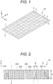
- a light control filter 10 illustrated in FIG. 1 as a first embodiment of this disclosure includes a first principal surface 1 and a second principal surface 2 on an opposite side, light-transmitting portions 3 that extend between the first principal surface 1 and the second principal surface 2, and a light-shielding portion 4 that extends between the first principal surface 1 and the second principal surface 2.
- the light-transmitting portions 3 and the light-shielding portion 4 form a sea-island structure.
- the light-transmitting portions 3 form a plurality of island portions 5 that penetrate through the light control filter from the first principal surface 1 to the second principal surface 2, and the light-shielding portion 4 that does not form the island portions 5 forms a sea portion 6 configured to separate the plurality of island portions 5 from one another.
- the sea portion 6 has an MD-1 rubber hardness of 25 or more and 80 or less.
- the MD-1 rubber hardness is preferably 40 or more and 75 or less, more preferably 50 or more and 70 or less.
- the MD-1 rubber hardness is equal to or more than the above-mentioned lower limit value, it becomes easy to cut an excess residual film after the light control filter 10 is taken out from a molding mold at the time of manufacturing, and a smooth principal surface can be easily obtained.
- the MD-1 rubber hardness is equal to or less than the above-mentioned upper limit value, it becomes easy to take out the light control filter 10 from the molding mold at the time of manufacturing.
- the MD-1 rubber hardness is a value measured from the light control filter 10 formed only of the sea portion 6 by pressing the sea portion of the light control filter in a thickness direction of a sheet at a temperature of from 21°C to 25°C, preferably 23°C through use of a micro rubber hardness meter.
- the hardness is measured by reading, with a detector, the amount of displacement generated when the surface of a test piece is deformed with pressing needles provided in the micro rubber hardness meter.
- the locations which are pressed with the pressing needles are set to be ten or more randomly selected locations in the sea portion, and an average value thereof is defined as a measurement value.
- the MD-1 rubber hardness indicates a value close to a value (Shore A hardness) measured with a type A durometer specified under JIS K6253-3:2012.
- the hardness of a thin test piece can be easily measured.
- the thickness of the sea portion of the light control filter (test piece) is less than 1.0 mm, a plurality of the same light control filters are stacked to form a laminate, and the hardness in a thickness direction of a laminate of 1.0 mm or more obtained by stacking a minimum number of the light control filters is measured.
- the micro rubber hardness meter to be used is preferably "Micro Rubber Hardness Meter” product name: MD-1capa manufactured by Kobunshi Keiki Co., Ltd.
- the load system of this micro rubber hardness meter is a cantilever plate spring. The measurement is performed by setting a pressing needle shape to type A (height: 0.50 mm, ⁇ 0.16 mm, columnar shape), pressure leg dimensions to type A (outer diameter: 4.0 mm, inner diameter: 1.5 mm), a spring load to 22 mN (2.24 g), and a measurement mode to a normal mode, respectively.
- the island portions 5 are removed by laser irradiation, chemical etching, or the like to obtain the light control filter 10 formed only of the sea portion 6, and the resultant is used as a test piece.
- the temperature of each of the test piece to be measured for an MD-1 rubber hardness and a test chamber is set to from 21°C to 25°C, preferably 23°C.
- the sea portion 6 having the above-mentioned MD-1 rubber hardness include an elastomer and be formed of the elastomer.
- the MD-1 rubber hardness of the entire light control filter 10 including the sea portion 6 and the island portions 5 is preferably 25 or more and 80 or less, more preferably 40 or more and 75 or more, still more preferably 50 or more and 70 or more.
- the MD-1 rubber hardness of the entire light control filter 10 fall within the above-mentioned ranges because the light control filter 10 has high flexibility and can be easily elastically deformed.
- the MD-1 rubber hardness of the entire light control filter 10 is obtained by measuring an MD-1 rubber hardness in a thickness direction of the light control filter 10 in each of ten or more randomly selected locations based on the above-mentioned measurement method, and averaging those measurement values.
- thermosetting elastomers such as a urethane rubber, an isoprene rubber, an ethylene propylene rubber, a natural rubber, an ethylene propylene diene rubber, a styrene butadiene rubber, and a silicone rubber
- thermoplastic elastomers such as urethane-based, ester-based, styrene-based, olefin-based, butadiene-based, and fluorine-based elastomers
- a silicone rubber is preferred.
- the silicone rubber has a small dimensional change after being taken out from a molding mold described later, and is not warped after being taken out from the molding mold.
- the silicone rubber has a small compression set and high heat resistance, and is also excellent in weather resistance and cold resistance.
- the elastomer is preferably a polymer having a Shore A hardness, which is measured through use of a durometer in accordance with JIS K6253-3:2012, of A25 or more and A80 or less, more preferably a polymer having a Shore A hardness of A40 or more and A75 or less, still more preferably a polymer having a Shore A hardness of A50 or more and A70 or less.
- the reasons that the silicone rubber is preferred are as described above.
- the light control filter 10 has a rectangular sheet shape.
- a longitudinal direction thereof is defined as the X-direction (the left-right direction of the drawing sheet in FIG. 2 ), a short direction thereof is defined as the Y-direction (the vertical direction of the drawing sheet in FIG. 2 ), and a direction perpendicular to the principal surface thereof (that is, the thickness direction of the sheet) is defined as the Z-direction.
- the shape of the light control filter 10 in plan view is not limited to a rectangle, and a circle, an ellipse, a polygon, or any other shapes may be adopted.
- the vertical and horizontal sizes of the light control filter 10 are not particularly limited, and may be set to, for example, sizes of from 5 mm ⁇ 5 mm to 100 cm ⁇ 100 cm.
- the thickness of the light control filter 10 is, for example, preferably 50 ⁇ m or more and 1,000 ⁇ m or less, more preferably 80 ⁇ m or more and 500 ⁇ m or less, still more preferably 100 ⁇ m or more and 300 ⁇ m or less.
- the thickness is equal to or more than the above-mentioned lower limit value, it becomes easier to control the viewing angle of light.
- the thickness is equal to or less than the above-mentioned upper limit value, the flexibility becomes higher.
- the thickness of the light control filter 10 is determined as an average value of values measured in ten or more randomly selected cross-sections.
- Known microstructure observation means such as a measurement microscope, is applied to the measurement.
- the light control filter 10 has a sea-island structure including the plurality of island portions 5 forming the light-transmitting portions 3 (sometimes referred to as “first portions") and the sea portion 6 forming the light-shielding portion 4 (sometimes referred to as "second portion").
- a main body of the light control filter 10 is a sheet.
- One surface of the sheet is referred to as "first principal surface”, and another surface is referred to as "second principal surface”.
- the total area of the sea portion 6 with respect to the total area of the first principal surface 1 is preferably from 36% to 99.2%, more preferably from 49% to 96%, still more preferably from 65% to 91%. It is preferred that the total area of the sea portion 6 on the second principal surface 2 be also similar to that of the sea portion 6 on the first principal surface 1.
- the total area of the island portions 5 and the sea portion 6 on each principal surface is determined by subjecting an image obtained by photographing each principal surface to image processing by a known method.
- the light beam transmittance of each of the light-transmitting portions 3 is preferably 70% or more, more preferably 80% or more, still more preferably 90% or more.
- the light beam transmittance of the light-transmitting portions 3 may be 100%. When the light beam transmittance is equal to or more than the above-mentioned lower limit value, the amount of light passing through the light control filter 10 is sufficient.
- the light beam transmittance of the light-shielding portion 4 is preferably less than 70%, more preferably less than 50%, still more preferably less than 30%, particularly preferably less than 10%.
- the light beam transmittance of the light-shielding portion 4 may be 0%. When the light beam transmittance is less than the above-mentioned upper limit value, the viewing angle is sufficiently controlled by the light control filter 10.
- the light beam transmittance of each of the light-transmitting portions 3 be 70% or more and 100% or less, and the light beam transmittance of the light-shielding portion 4 be 0% or more and less than 70%. It is more preferred that the light beam transmittance of each of the light-transmitting portions 3 be 80% or more and 100% or less, and the light beam transmittance of the light-shielding portion 4 be 0% or more and less than 50%. It is still more preferred that the light beam transmittance of each of the light-transmitting portions 3 be 90% or more and 100% or less, and the light beam transmittance of the light-shielding portion 4 be 0% or more and less than 30%.
- “A” represents an output value of the light-receiving sensor in a state in which there is no object to be measured on an optical path of the inspection light
- “B” represents an output value in a state in which an object to be measured is set on the optical path of the inspection light, and the transmitted light transmitted through the object to be measured is received by the light-receiving sensor.
- the light-transmitting portions 3 of the light control filter 10 correspond to the island portions 5 in the sea-island structure and a plurality of columnar transparent portions that are separated from one another by the sea portion 6.
- Each of the island portions 5 penetrates through the light control filter 10. Therefore, a first end portion of each of the island portions 5 is exposed to the first principal surface 1 of the light control filter 10, and a second end portion of each of the island portions 5 is exposed to the second principal surface 2 of the light control filter 10.
- the respective island portions 5 are arranged at a constant pitch along the X-direction and the Y-direction.
- each of the island portions 5 that penetrate through the light control filter 10 in the Z-direction be a columnar shape.
- the island portion 5 having a columnar shape means that the island portion 5 is recognized as a three-dimensional columnar shape when it is assumed that the island portion 5 is taken out from the light control filter 10.
- the height direction of the columnar shape is along the thickness direction of the light control filter 10.
- An upper surface (top surface) and a bottom surface of a column forming the columnar shape are parallel to the first principal surface 1 and the second principal surface 2, respectively.
- sectional shape obtained by cutting the island portion 5 in the XY-plane there are given, for example, a circle, an ellipse, a rectangle, and other polygons.
- the sectional shape of the first end portion of the island portion 5 exposed to the first principal surface 1 (planar shape of the island portion 5 on the first principal surface 1) and the sectional shape of the second end portion exposed to the second principal surface 2 (planar shape of the island portion 5 on the second principal surface 2) may be identical to or different from each other. From the viewpoint of ease of light control, it is preferred that the sectional shapes be identical to each other.
- the sectional shapes of the respective island portions may be identical to or different from each other. From the viewpoint of ease of light control, it is preferred that the sectional shapes be identical to each other.
- An axial line of a center axis of the columnar island portion 5 may be perpendicular or inclined with respect to the first principal surface 1 and the second principal surface 2. From the viewpoints of ease of manufacturing and ease of viewing angle control, it is preferred that the axial line be substantially perpendicular to the first principal surface 1 and the second principal surface 2.
- substantially perpendicular refers to intersecting at 90° ⁇ 2°.
- the angle formed by the axial line and the principal surface, and the height H of the island portion 5 are determined by measuring a cross-section including the island portion 5 and the principal surface with known microstructure observation means, such as a measurement microscope.
- the height H of the island portion 5 is a distance between the first principal surface 1 and the second principal surface 2.
- a size R of the end portion exposed to each principal surface is a diameter of a smallest circle including the end portion.
- the diameter is, for example, preferably from 5 ⁇ m to 100 ⁇ m, more preferably from 10 ⁇ m to 50 ⁇ m from the viewpoint of ease of control of the viewing angle of light transmitted through the light control filter 10.
- the diameter is equal to or more than the above-mentioned lower limit value, breakage of a part (for example, a columnar protruding portion) of the molding mold to be used at the time of manufacturing, which corresponds to the island portion 5, can be prevented.
- the diameter is equal to or less than the above-mentioned upper limit value, an aspect ratio described later can be easily increased even when the light control filter 10 is thin.
- the sizes R of two end portions exposed to the respective principal surfaces of the single island portion 5 may be identical to or different from each other.
- An average of the diameters of ten or more island portions 5 that are randomly selected from the plurality of island portions 5 on an arbitrary principal surface of the light control filter 10 is preferably from 5 ⁇ m to 100 ⁇ m, more preferably from 10 ⁇ m to 50 ⁇ m.
- the diameter may be measured with known microstructure observation means, such as a measurement microscope.
- the aspect ratio represented by (size R:height H) of the columnar island portion 5 is preferably from 1:5 to 1:30, more preferably from 1:8.5 to 1:25.5.
- a viewing angle ⁇ is from 22.6° to 3.6°.
- the viewing angle ⁇ is from 13.4° to 4.5°.
- the refractive index of the transparent material is usually larger than that of air, and hence the viewing angle ⁇ is widened as compared to the range in the case in which the island portion 5 is hollow as described above. Therefore, from the viewpoint of narrowing the viewing angle ⁇ , it is preferred that the island portion 5 be hollow.
- the amount of light transmitted through the island portion 5 of the light control filter 10 can be increased.
- the light control filter 10 can be relatively easily manufactured.
- the aspect ratio is a ratio between an average value obtained by measuring the sizes R of both the end portions and an average value obtained by measuring the heights H in ten or more island portions 5 randomly selected from the plurality of island portions 5 of the light control filter 10.
- Each of the sizes R and each of the heights H may be measured through use of known microstructure observation means, such as a measurement microscope.
- a pitch P of the arrangement of the island portions 5 on the first principal surface 1 and the second principal surface 2, that is, the pitch P between adjacent end portions of the island portions 5 exposed to each of the principal surfaces is a distance between centers of smallest circles each including an end portion.
- the pitch P is, for example, preferably from 10 ⁇ m to 500 ⁇ m, more preferably from 15 ⁇ m to 300 ⁇ m, still more preferably from 20 ⁇ m to 200 ⁇ m from the viewpoint of ease of control of the viewing angle of light transmitted through the light control filter 10.
- the pitch P is equal to or more than the above-mentioned lower limit value, it becomes easy to produce a molding mold to be used for manufacturing.
- the pitch P is equal to or less than the above-mentioned upper limit value, the visibility of an image viewed through the light control filter 10 is increased, and a sufficient resolution is easily obtained.
- the pitch P is preferably constant on each of the principal surfaces.
- the pitch P between the respective principal surfaces may be identical to or different from each other.
- the pitch P is determined by subjecting an image obtained by photographing an arbitrary principal surface to image processing by a known method.
- the pitch P on an arbitrary principal surface varies depending on the region of the principal surface, it is preferred that the pitch P of three or more consecutive island portions 5 fall within the above-mentioned ranges. It is more preferred that the pitch P of five or more consecutive island portions 5 fall within the above-mentioned ranges. It is still more preferred that the pitch P of ten or more consecutive island portions 5 fall within the above-mentioned ranges.
- the arrangement of the island portions 5 on the first principal surface 1 and the second principal surface 2 is a two-dimensional array arrangement of X columns ⁇ Y rows.
- the arrangement of the island portions 5 is not limited to this example, and any arrangement patterns are adopted.
- X columns ⁇ Y rows for example, X and Y may be independently set to any integers of from 10 to 1,000.
- each line segment connecting the centers of the adjacent island portions 5 in an arbitrary column is located on one straight line
- each line segment connecting the centers of the adjacent island portions 5 in an arbitrary row is located on one straight line.
- the above-mentioned straight line representing each column and the above-mentioned straight line representing each row intersect with each other at about 90°.
- the arrangement pattern may be a two-dimensional array shape, a zigzag shape, any other patterns, or an arbitrary random arrangement.
- the array direction of the island portions 5 of each column (direction of the straight line representing each column) is parallel to a side in the X-direction forming an outer edge of the light control filter 10
- the array direction of the island portions 5 of each row (direction of the straight line representing each row) is parallel to a side in the Y direction forming an outer edge of the light control filter 10.
- the Y rows of the two-dimensional array of X columns ⁇ Y rows including the plurality of island portions 5 may be arranged in a direction that is not parallel to the side in the Y-direction of the outer edge but intersects therewith.
- the X rows of the two-dimensional array are arranged in a direction that is not parallel to the side in the X-direction of the outer edge but intersects therewith.
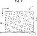
- FIG. 7 when the Y-direction of the outer edge of the light control filter 30 is represented by a straight line Q1, and the array direction of the Y rows of the island portions 5 is represented by a straight line Q2, the straight line Q1 and the straight line Q2 intersect with each other at an angle ⁇ .
- the angle ⁇ of an intersection between the side in the Y-direction and the Y rows may be arbitrarily adjusted, and is set to preferably from 10° to 30°, for example, on an acute angle side.
- the intersection angle is provided as described above, when the light control filter is aligned to be bonded to a frame of a display screen, the occurrence of interference fringes (moire) caused by interference between the pixel array pattern on the display screen and the array pattern of the plurality of island portions 5 included in the light control filter can be reduced.
- the light-transmitting portions 3 that are the island portion 5 of the light control filter 10 are through holes formed in the light-shielding portion 4 that is the sea portion 6.
- Each of the through holes may be filled with air or may be filled with a light-transmitting material.
- the refractive index of transmitted light is small, and hence the viewing angle ⁇ can be reduced.
- the through hole is filled with a light-transmitting material, the shape of the through hole is easily kept by the light-transmitting material, and the shape of each of the light-transmitting portions 3 is easily kept even when the light control filter 10 is deformed.
- the light-transmitting material examples include a transparent resin and glass. From the viewpoint of increasing the flexibility of the light control filter 10, a transparent elastomer is preferred. Specific examples of the transparent elastomer include silicone and polyurethane. The number of the kinds of the transparent elastomer filled into the through hole may be one or two or more. From the viewpoints of excellent transparency, heat resistance, and the like, the transparent elastomer is preferably a silicone rubber.
- the light-shielding portion 4 of the light control filter 10 is the sea portion 6 in the sea-island structure, and is an opaque portion excluding the island portions 5.
- the length in the Z-direction of the light-shielding portion 4 is the same as the thickness of the light control filter 10, and is preferably 50 ⁇ m or more and 1,000 ⁇ m or less, more preferably 80 ⁇ m or more and 500 ⁇ m or less, still more preferably 100 ⁇ m or more and 300 ⁇ m or less.
- the length is equal to or more than the above-mentioned lower limit value, it becomes easy to control the viewing angle (transmission angle) ⁇ of light.
- the length is equal to or less than the above-mentioned upper limit value, the flexibility is further increased.
- the content of the elastomer with respect to the total mass of the light-shielding portion 4 is preferably from 50 mass% to 99 mass%, more preferably from 60 mass% to 97 mass%, still more preferably from 70 mass% to 95 mass%.
- the flexibility of the light control filter 10 is sufficiently increased.
- the content is equal to or less than the above-mentioned upper limit value, there can be room for sufficient inclusion of a light-shielding material in the light-shielding portion 4.
- the remaining part excluding the content of the elastomer in the total mass may be allocated to the light-shielding material.
- the light control filter 10 is formed of an elastomer, and hence the light control filter 10 can be easily removed from the molding mold, and processing required for adjusting the thickness is also facilitated.
- the light control filter 10 be formed of an elastomer because the light control filter 10 is reduced in weight as compared to the case in which the light control filter 10 is formed of silicon or a metal.
- a known elastomer is applied to the elastomer forming the light-shielding portion 4, and the elastomer may be transparent or opaque.
- the number of the kinds of the elastomer forming the light-shielding portion 4 may be one or two or more.
- the light-transmitting portions 3 each include an elastomer
- the adhesiveness between the light-shielding portion 4 and the light-transmitting portions 3 is increased, and the light-shielding portion 4 and the light-transmitting portions 3 are integrated to sufficiently increase the flexibility of the light control filter 10. Therefore, it is preferred that the elastomer included in the light-transmitting portions 3 and the elastomer included in the light-shielding portion 4 be the same.
- the elastomer included in the light-shielding portion 4 is preferably a silicone rubber.
- the light-shielding portion 4 include a light-shielding material in addition to the elastomer.
- a light-shielding material at least one of a light-absorbing material or a light-reflecting material is used.
- the light-absorbing material contains a light-absorbing agent.
- the light-absorbing agent include carbon, a dye, and a pigment.
- carbon is preferred because the light-absorbing property thereof is excellent.
- the carbon include carbon black, graphite, and carbon fibers, and carbon black is preferred because carbon black is widely used as a light-absorbing agent.
- the light-reflecting material is a metal.
- the metal include aluminum, silver, gold, chromium, and nickel.
- a light control filter 20 illustrated in FIG. 4 as a second embodiment of this disclosure includes the light control filter 10 according to the first embodiment as a main body, and a first transparent sealing layer 7 and a second transparent sealing layer 8 are laminated on the principal surfaces 1 and 2 of the main body, respectively.
- Each of the transparent sealing layers of the light control filter 20 covers each of the principal surfaces of the main body to protect the main body.
- each of the transparent sealing layers is present, when the light-transmitting portions 3 are cavity through holes, foreign matter can be prevented from entering the through holes from outside.
- each of the transparent sealing layers is smooth, irregular reflection of light on the surface is prevented, and an opposite side of the light control filter 20 can be seen through the light-transmitting portions 3.
- An arithmetic average roughness (Ra) of the exposed surface of each of the transparent sealing layers is preferably 0 ⁇ m or more and 1 ⁇ m or less, more preferably 0 ⁇ m or more and 0.2 ⁇ m or less.
- the arithmetic average roughness (Ra) falls within the above-mentioned ranges, irregular reflection of light on the surface of the transparent sealing layer is suppressed, and light is enabled to be easily transmitted.
- the arithmetic average roughness (Ra) is a value determined in accordance with JIS B0601:2013 (ISO 4287:1997) .
- a constituent material for each of the transparent sealing layers only needs to be transparent, and examples thereof include glass and a transparent synthetic resin. Specific examples thereof include a silicone, a polyurethane, an acrylic resin, an epoxy resin, a polyester, a polycarbonate, a cycloolefin, and a liquid crystal polymer.
- the material forming the transparent sealing layer is preferably an elastomer similar to the elastomer included in the sea portion 6 forming the main body.
- the transparent sealing layer is glass, rigidity can be imparted to the light control filter 20, and the heat resistance can be further improved.
- the transparent sealing layer is glass
- Examples of the surface treatment include excimer UV irradiation treatment, plasma treatment, and primer application treatment using a silane coupling agent or the like.
- the first transparent sealing layer 7 and the second transparent sealing layer 8 may be each formed of the same transparent material, or may be formed of different transparent materials.
- Each of the first transparent sealing layer 7 and the second transparent sealing layer 8 may be formed as a plurality of layers.
- the respective layers may be formed of the same transparent material or different materials .
- a laminate of a glass layer and a transparent resin layer may form the above-mentioned transparent sealing layer.
- the glass layer may be brought into contact with the principal surface of the sheet, or the transparent resin layer may be brought into contact with the principal surface of the sheet.
- the thickness of each of the transparent sealing layers is preferably 1 ⁇ m or more and 200 ⁇ m or less, more preferably 3 ⁇ m or more and 175 ⁇ m or less, still more preferably 5 ⁇ m or more and 150 ⁇ m or less.
- the thickness of the transparent sealing layer is equal to and more than the above-mentioned lower limit value, the main body of the light control filter can be sufficiently protected, and the irregularities of each of the principal surfaces of the main body can be sufficiently smoothened, with the result that the thickness of each of the transparent sealing layers can be easily controlled at the time of manufacturing.
- the thickness of each of the transparent sealing layers is equal to or less than the above-mentioned upper limit value, a sufficient light-transmitting property can be ensured, and satisfactory optical characteristics are obtained.
- the thickness of the transparent sealing layer is determined as an average value of values measured in ten or more randomly selected cross-sections.
- Known microstructure observation means such as a measurement microscope, is applied to the measurement.
- the MD-1 rubber hardness of the sea portion 6 of the light control filter 20 is a value measured by removing the first transparent sealing layer 7 and the second transparent sealing layer 8 to obtain only a sheet forming the sea-island structure.
- the light control filters according to the first and second embodiments described above each include the light-transmitting portions 3 that are the island portions 5 and the light-shielding portion 4 that is the sea portion 6.
- the light-transmitting portions 3 that are the island portions 5
- the light-shielding portion 4 that is the sea portion 6.
- a light beam having entered the columnar island portions 5 is transmitted therethrough and emitted from the second principal surface 2, and a light beam having entered the sea portion 6 is absorbed or reflected by the sea portion 6.
- the pitch P, the size R, and the aspect ratio of the light-transmitting portions 3 of the columnar island portions 5 are appropriately adjusted, the viewing angle (transmission angle) ⁇ of the light beam, and the amount of transmitted light can be controlled.
- the sea portion 6 has an MD-1 rubber hardness of 25 or more and 80 or less, and hence the light control filter 10 has high flexibility, and is easily elastically deformed.
- the MD-1 rubber hardness of the entire light control filter 10 is 25 or more and 80 or less, the light control filter 10 has higher flexibility, and is more easily elastically deformed. Therefore, it is not required to laminate a support layer configured to maintain the mechanical strength of the light control filter 10, and the light control filter 10 can be handled in the form of a single body as a single layer light control filter.
- the support layer is laminated, the thickness of the support layer is added. Therefore, light is attenuated in the support layer, and the light-transmitting property is decreased. In contrast, when there is no support layer that causes attenuation of light, the light-transmitting property is increased.
- the light control filter 10 it is not required to laminate the support layer, and hence the light control filter 10 can be reduced in thickness.
- the lamination of the support layer is not suitable for the purpose of reducing thickness because the thickness of the support layer is added.
- the light control filter 10 that can be reduced in thickness can reduce the occupied space thereof in a device to which the light control filter is to be mounted, and hence the light control filter 10 contributes to the reduction in thickness of the device.
- the flexibility of the light control filter 10 that is the main body of the light control filter 20 and the ease of reduction in thickness thereof are useful.
- Light control filters (not shown) according to third and fourth embodiments of this disclosure each include light-shielding portions that are island portions and a light-transmitting portion that is a sea portion.
- the light control filters according to the third and fourth embodiments of this disclosure are the same as those according to the first and second embodiments except that the light-shielding portion and the light-transmitting portion are inverted.
- the sea portion may include materials other than the elastomer.
- the island portion includes the above-mentioned light-shielding material, and may include a known binder in addition thereto. From the viewpoint of enhancing the adhesion between the sea portion and the island portions, it is preferred that an elastomer of the same kind as that of the elastomer forming the sea portion be included also in the island portions.
- the light control filters according to the third and fourth embodiments described above each include the light-shielding portions that are the island portions and the light-transmitting portion that is the sea portion.
- a light beam having entered the columnar island portions is absorbed or reflected by the columnar island portions, and a light beam having entered the sea portion is transmitted therethrough and emitted from the second principal surface.
- the viewing angle (transmission angle) of the light beam, and the amount of transmitted light can be controlled.
- the light control filter according to this disclosure is mounted on an image display apparatus, such as a liquid crystal display apparatus, for example, for the purposes of viewing angle control, brightness improvement, antiglare treatment, and the like.
- the light control filter may be mounted on, for example, a light-emitting body, such as a light-emitting diode or an organic electroluminescence element, or a light-receiving body, such as an optical sensor.
- a method of manufacturing the light control filter of this disclosure for example, there is given a method involving molding a sheet through use of a molding mold having irregularities formed thereon and transferring the irregularities of the molding mold onto the sheet.
- a liquid elastomer precursor L containing a light-shielding material is applied to the surface of a molding mold K in which a recess M corresponding to the sea portion 6 in the sea-island structure of the light control filter 10 according to the first embodiment is formed.
- a liquid elastomer precursor L containing a light-shielding material is applied to the surface of a molding mold K in which a recess M corresponding to the sea portion 6 in the sea-island structure of the light control filter 10 according to the first embodiment is formed.
- the elastomer precursor L filled into the recess M of the molding mold K is cured, to thereby form the light control filter 10 in the molding mold K.
- a protruding portion (non-recess portion) of the surface of the molding mold K is present.
- the elastomer precursor L having overflowed from the recess M without entering the recess M becomes a residual film N that covers one principal surface of the light control filter 10.
- the excess residual film N is removed by cutting or polishing, and the target light control filter 10 is taken out from the molding mold K.
- each of the island portions 5 that penetrate through the obtained light control filter 10 in a thickness direction thereof is a cavity ( FIG. 5(c) ), and may be filled with a light-transmitting material as required ( FIG. 5 (d) ).
- the first transparent sealing layer 7 and the second transparent sealing layer 8 are laminated on the first principal surface 1 and the second principal surface 2 of the light control filter 10, respectively, by a conventional method, the light control filter 20 according to the second embodiment is obtained ( FIG. 5(e) ).
- the molding mold K is a flat sheet in which a recess for forming the sea portion 6 and a plurality of columnar protruding portions (non-recess portions) for forming the island portions 5 in the recess are formed on the surface.
- the depth of the recess and the height of the protruding portion are the same.
- the pitch between the protruding portions corresponds to the pitch P between the island portions 5
- the height of the protruding portion corresponds to the height of the island portion 5
- the size of the protruding portion corresponds to the size R of the island portion 5.
- the axial line direction of a central axis of each of the protruding portions and the side surface of the protruding portion are arranged so as to be perpendicular to the bottom surface of the molding mold K.
- the side surface of the island portion 5 in the obtained light control filter 10 can be formed so as to be perpendicular to each principal surface of the light control filter 10.
- a method of producing the molding mold K there are given, for example, a method involving forming the recess M by subjecting one surface of a base material having a flat sheet shape to dry etching and a method involving forming the recess M by cutting one surface of a base material having a flat sheet shape.
- a base material having a flat sheet shape there are given, for example, a silicon wafer and a quartz substrate.
- Examples of the dry etching include plasma etching, laser etching, and ion etching.
- a method for the plasma etching there is given a method involving arranging a mask on a surface of a base material and irradiating a substrate surface with plasma through the mask to etch only the surface that is not covered with the mask, to thereby form the recess M.
- the liquid elastomer precursor L there are given, for example, curable compounds, such as a curable silicone, an isocyanate, and a polyol.
- a polymerization catalyst may be added to the elastomer precursor L.
- a thermal polymerization catalyst is added.
- a photopolymerization catalyst is used.
- the above-mentioned light-shielding material may be added to the elastomer precursor L. When the light-shielding material is added, the light-shielding portion 4 is formed in the sea portion 6.
- the light-transmitting portion 3 is formed in the sea portion 6.
- Other components such as a solvent, may be further mixed with the elastomer precursor L as required (the same applies also to the following methods).
- the support film a film which can be easily peeled from the obtained light control filter 10 is preferred, and there are given, for example, a polyethylene terephthalate film, a polypropylene film, and the like.
- a method of applying the elastomer precursor L to the support film there is given a method using a known coater. The amount of the elastomer precursor L applied to the support film is adjusted to an amount sufficient for manufacturing the target light control filter 10.
- the elastomer precursor L is filled into the recess M by pressing the recess M of the molding mold K against the film of the elastomer precursor L formed on the support film, to thereby form irregularities in which irregular shapes are inverted on the film.
- a method of thermally curing the elastomer precursor L there are given, for example, a method involving heating the molding mold K pressed against the film, and a method involving heating the molding mold K through use of an external heater provided separately from the molding mold K.
- the elastomer precursor L is photocured, for example, the elastomer precursor L is photocured by irradiation with UV light or an electron beam.
- the light control filter 10 can be formed.
- the amount of the elastomer precursor L that is caused to flow down to the recess M of the molding mold K is adjusted to an amount with which the target light control filter 10 is obtained.
- the surface of the elastomer precursor L is levelled with a spatula or the like, to thereby fill the elastomer precursor L into the recess M.
- the elastomer precursor L is cured to form the light control filter 10.
- a curing method the same method as that in the above-mentioned (a-1) may be adopted.
- a method of applying the elastomer precursor L in the method (a-3) there is given, for example, a method involving pressing and spreading the elastomer precursor L against the liquid elastomer precursor L adhering to an arbitrary position of the recess M of the molding mold K by pressing a pressing die, to thereby fill the elastomer precursor L into the recess M.
- a known coater may be adopted as the application method.
- the same method as that in the above-mentioned (a-1) may be adopted.
- the method (a-4) is a press molding method using a known press molding machine.
- the light control filter 10 can be formed by mounting the molding mold K on the press molding machine and press-molding an elastomer.
- the elastomer may contain the light-shielding material and other components.
- the method (a-5) is an injection molding method using a known injection molding machine.
- the light control filter 10 can be formed by mounting the molding mold K on the injection molding machine and molding an elastomer.
- the elastomer may contain the light-shielding material and other components.
- the elastomer precursor L having overflowed from the recess M without entering the recess M becomes the residual film N.
- the shape of an edge of an opening of the recess M (shape of a distal end of the protruding portion) is easily reflected on the shape of an end portion of the island portion 5 of the light control filter 10 to be formed, that is, the island portion 5 reflecting the shape of the recess M can be formed with satisfactory accuracy.
- a method of removing the excess residual film N after curing there are given, for example, a known contact method involving cutting or polishing a surface of a general substrate, and a known non-contact method, such as laser processing and plasma treatment.
- the light control filter 10 When the light control filter 10 is shaped into a desired form, it is preferred that the light control filter 10 be cooled to, for example, a temperature of from -10°C to -50°C, preferably from -20°C to -40°C to increase the hardness of the light control filter 10, and then the light control filter be cut, because shaping processing, such as cutting, is facilitated.
- the Shore A hardness of the sea portion 6 of the light control filter 10 is A50 or more, the light control filter 10 can be easily subjected to cutting processing at an ordinary temperature (for example, from 20°C to 25°C) .
- the light control filter 10 has flexibility and is elastically deformed. Therefore, it is relatively easy to take out the light control filter 10 from the molding mold K, and the irregularities of the molding mold K can be prevented from being broken when the light control filter 10 is taken out.
- the paint filled into the through holes is cured by a conventional method.
- the paint contain a curable resin precursor or a binder.
- the light-transmitting portions 3 can be formed in the island portions 5.
- the light-shielding portions 4 can be formed in the island portions 5.
- the resin precursor examples include a thermosetting silicone, an isocyanate and a polyol forming a polyurethane, an acrylic compound, an epoxy compound, and an unsaturated polyester.
- a light-transmitting material may be set in each of the island portions 5 by inserting an optical fiber made of a resin or glass that is fitted with the island portion 5 into the island portion 5.
- the land film is not present in each of the island portions 5 of the light control filter 10, and hence the paint can be easily caused to flow into the island portion 5, and the light-transmitting member can be easily inserted into the island portion 5.
- a conventional method of forming a transparent layer on the surface of a general substrate is applied. Specifically, there are given, for example, the following methods (c-1) and (c-2).
- thermosetting compound and the photocurable compound examples include an acrylic compound, an epoxy compound, a thermosetting silicone, and an isocyanate and a polyol forming a polyurethane.
- the paint containing those curable compounds may contain a polymerization initiator.
- the polymerization initiator include organic peroxides and azo compounds.
- the paint may contain a known organic solvent.
- the method involving laminating a transparent resin film or transparent glass there are given, for example, a method involving bonding through use of an adhesive and a method involving thermocompression bonding.
- a residual film R remains on the second principal surface 2 of the light control filter 10 before or after a light-transmitting member is set in each of the island portions 5 of the light control filter 10 according to each embodiment, as a suitable method of removing the residual film R and molding the first principal surface 1 on a surface parallel to the second principal surface 2, there is given a method exemplified below.
- a method exemplified below there is illustrated a case of removing the residual film R of the light control filter 10 after the light-transmitting member is set in each of the island portions 5.
- the residual film R can be removed by the same method also in the light control filter 10 in which the island portions 5 immediately after demolding are hollow (cavities).
- the residual film R corresponds to the residual film N of FIGS. 5 .
- the residual film R remaining on the second principal surface 2 of the light control filter 10 is fixed in close contact with a flat support surface S of a support stage.
- the thickness of the residual film R may be non-uniform, and in the figure, the residual film R is drawn so as to emphasize that the residual film R is increased in thickness toward the right side of the drawing sheet.
- a cutting blade or a laser is moved in parallel to the support surface S to cut to slice the light control filter 10 at a position as close as possible to a boundary between the residual film R and the second principal surface 2 (for example, a position indicated by the broken line C1 of the figure) so as not to include the residual film R, to thereby form a new flattened second principal surface 2.
- the first principal surface 1 and the second principal surface 2 of the light control filter 10 that has been cut out may be non-parallel to each other.
- the new second principal surface 2 of the light control filter 10 is fixed in close contact with the flat support surface S of the support stage.
- the cutting blade or laser is moved again in parallel to the support surface S to cut the light control filter 10 at a position as close as possible to the original first principal surface 1 (for example, a position indicated by the broken line C2 of the figure) so as not to leave the original first principal surface 1, to thereby form a new flattened first principal surface 1.
- the first principal surface 1 and the second principal surface 2 of the light control filter 10 that has been cut out are parallel to each other in this stage.
- an angle formed by a straight line connecting the first end portion and the second end portion of each of the island portions 5 with respect to the first principal surface 1 and the second principal surface 2 is changed before and after the residual film R is excised due to the non-uniformity of the thickness of the residual film R.
- the island portions 5 are perpendicular to the original first principal surface 1 but are inclined to the new first principal surface 1.
- the residual film R can be easily excised, and the first principal surface 1 and the second principal surface 2 that are smooth and parallel to each other are molded.
- the light control filter 10 having a small thickness, in which the first end portion and the second end portion of each of the island portions 5 are exposed to the first principal surface 1 and the second principal surface 2, respectively, can be easily obtained.
- a molding mold made of silicon made of Si
- a recess having dimensions of 20 mm ⁇ 20mm ⁇ 180 ⁇ m (length ⁇ width ⁇ depth) was formed on the surface, and 400 ⁇ 400 columnar protruding portions (diameter: 30 ⁇ m, height: 180 ⁇ m) were arrayed in a grid shape at pitches of 50 ⁇ m along the X-Y direction in the recess.
- thermosetting silicone manufactured by Shin-Etsu Chemical Co., Ltd., KE-1935
- carbon black were mixed to obtain a paint for forming a light-shielding portion.
- the content of the thermosetting silicone with respect to the total mass of the paint was adjusted to be about 95 mass% with respect to the total mass of a cured product obtained after the paint was cured.
- the paint for forming a light-shielding portion was applied to the surface of a polyethylene terephthalate film to form a thermosetting silicone film.
- the light control filter had flexibility, was elastically deformed, and had sufficient mechanical strength. Therefore, when the light control filter was taken out, the light control filter was able to be easily taken out without breaking the molding mold.
- a sea portion of the light control filter that has been taken out is formed of light-shielding silicone, and island portions thereof are through holes filled with air.
- MD-1 rubber hardness was measured through use of, as a test piece, a laminate (thickness: 1,080 ⁇ m) of stacked six light control filters each being formed only of the sea portion, which has been taken out from the molding mold, with "Micro Rubber Hardness Meter” product name: MD-1capa, manufactured by Kobunshi Keiki Co., Ltd. in an environment at 23°C in accordance with the above-mentioned measurement method (pressing needle shape: type A, pressure leg dimensions: type A, spring load: 22 mN, measurement mode: normal mode). As a result, the MD-1 rubber hardness was 55.
- liquid thermosetting silicone manufactured by Shin-Etsu Chemical Co., Ltd., KE-1935-A/B was placed on one principal surface of the light control filter. After the liquid thermosetting silicone was pushed into the through holes through use of a pressing die, the liquid thermosetting silicone was cured by heating to 130°C to form transparent silicone in the through holes.
- An MD-1 rubber hardness was measured through use of, as a test piece, a laminate (thickness: 1,080 ⁇ m) of the stacked six light control filters obtained herein, in which the sea portion and the island portions were each formed of a silicone rubber, with MD-1capa in an environment at 23°C in accordance with the above-mentioned measurement method. As a result, the MD-1 rubber hardness was 55.
- the sea portion of the obtained light control filter is formed of light-shielding silicone, and the island portions are each formed of transparent silicone.
- the obtained light control filter had flexibility, was able to be easily elastically deformed, had sufficient mechanical strength, and had high adhesion between the sea portion and the island portions, and the light beam transmittance of the light-transmitting portion formed in each of the island portions was excellent.
- both the principal surfaces of the light control filter were irradiated with a YAG laser to clean both the principal surfaces.
- the light control filter had flexibility, was elastically deformed, and had sufficient mechanical strength, and hence the light control filter was easy to handle as a single body.
Landscapes
- Physics & Mathematics (AREA)
- General Physics & Mathematics (AREA)
- Optics & Photonics (AREA)
- Spectroscopy & Molecular Physics (AREA)
- Engineering & Computer Science (AREA)
- General Engineering & Computer Science (AREA)
- Optical Elements Other Than Lenses (AREA)
- Optical Filters (AREA)
- Eye Examination Apparatus (AREA)
- Optical Communication System (AREA)
- Planar Illumination Modules (AREA)
Applications Claiming Priority (2)
| Application Number | Priority Date | Filing Date | Title |
|---|---|---|---|
| JP2018091448A JP2019197158A (ja) | 2018-05-10 | 2018-05-10 | 光制御フィルター |
| PCT/JP2019/018402 WO2019216342A1 (ja) | 2018-05-10 | 2019-05-08 | 光制御フィルター |
Publications (2)
| Publication Number | Publication Date |
|---|---|
| EP3816680A1 true EP3816680A1 (de) | 2021-05-05 |
| EP3816680A4 EP3816680A4 (de) | 2022-02-23 |
Family
ID=68467520
Family Applications (1)
| Application Number | Title | Priority Date | Filing Date |
|---|---|---|---|
| EP19799385.0A Pending EP3816680A4 (de) | 2018-05-10 | 2019-05-08 | Lichtsteuerfilter |
Country Status (7)
| Country | Link |
|---|---|
| US (1) | US12001037B2 (de) |
| EP (1) | EP3816680A4 (de) |
| JP (1) | JP2019197158A (de) |
| KR (1) | KR20210006398A (de) |
| CN (1) | CN112262328B (de) |
| TW (1) | TWI805750B (de) |
| WO (1) | WO2019216342A1 (de) |
Families Citing this family (3)
| Publication number | Priority date | Publication date | Assignee | Title |
|---|---|---|---|---|
| JP7372833B2 (ja) | 2019-12-27 | 2023-11-01 | 国立大学法人 東京大学 | 開口部用装置 |
| JP7407654B2 (ja) * | 2020-05-07 | 2024-01-04 | 信越ポリマー株式会社 | 光制御フィルターの製造方法 |
| WO2023214244A1 (en) * | 2022-05-06 | 2023-11-09 | 3M Innovative Properties Company | Light control film and method of fabricating same |
Family Cites Families (28)
| Publication number | Priority date | Publication date | Assignee | Title |
|---|---|---|---|---|
| JPH0515836A (ja) | 1991-07-16 | 1993-01-26 | Dainippon Printing Co Ltd | 方向選択性光線調整シートの製造方法 |
| JP3999206B2 (ja) | 2004-02-05 | 2007-10-31 | シャープ株式会社 | 視野角制御素子およびそれを用いた映像表示装置 |
| JP2007249052A (ja) * | 2006-03-17 | 2007-09-27 | Nec Corp | 光制御フィルム、照明装置、および表示装置 |
| JP4382791B2 (ja) * | 2006-05-16 | 2009-12-16 | Nec液晶テクノロジー株式会社 | 光線方向制御素子の製造方法 |
| JP2008089728A (ja) * | 2006-09-29 | 2008-04-17 | Nec Lcd Technologies Ltd | 光学素子、それを用いた照明装置、表示装置、および電子機器 |
| JP2008148445A (ja) | 2006-12-11 | 2008-06-26 | Fuji Electric Systems Co Ltd | 鉄道車両の駆動制御装置 |
| JP2007249210A (ja) * | 2007-03-15 | 2007-09-27 | Kureha Elastomer Co Ltd | 表示画面用光学フィルター |
| JP2008242175A (ja) * | 2007-03-28 | 2008-10-09 | Sumitomo Chemical Co Ltd | 薄膜パターンの形成方法及びカラーフィルタ用ブラックマトリックス基板の製造方法 |
| JP2009025472A (ja) * | 2007-07-18 | 2009-02-05 | Shin Etsu Polymer Co Ltd | 視野角制御シート |
| JP2009069477A (ja) * | 2007-09-13 | 2009-04-02 | Bridgestone Corp | ディスプレイ用光学フィルタ、これを備えたディスプレイ及びプラズマディスプレイパネル |
| JP5260259B2 (ja) * | 2008-12-22 | 2013-08-14 | 東洋紡株式会社 | 表示画面用光学フィルター |
| WO2012057257A1 (ja) * | 2010-10-29 | 2012-05-03 | 信越ポリマー株式会社 | 透明導電ガラス基板 |
| US9329311B2 (en) * | 2011-05-25 | 2016-05-03 | 3M Innovative Properties Company | Light control film |
| JP2013020118A (ja) * | 2011-07-12 | 2013-01-31 | Shin Etsu Polymer Co Ltd | 機能性遮光フィルム |
| JP6242578B2 (ja) * | 2012-03-27 | 2017-12-06 | 恵和株式会社 | 視野角制限シート及びフラットパネルディスプレイ |
| JP2013225008A (ja) * | 2012-04-20 | 2013-10-31 | Sharp Corp | 光制御フィルム、表示装置、および光制御フィルムの製造方法 |
| JP5898560B2 (ja) * | 2012-05-08 | 2016-04-06 | 東芝機械株式会社 | 覗き見防止フィルムおよび覗き見防止フィルムの製造方法 |
| JP2014008445A (ja) * | 2012-06-28 | 2014-01-20 | Sumitomo Chemical Co Ltd | 封口用マスク、並びに、これを用いたハニカム構造体の封口方法及びハニカムフィルタの製造方法 |
| EP2920645A4 (de) * | 2012-12-20 | 2016-04-13 | Nokia Technologies Oy | Vorrichtung mit einer blitzlichtschaltungsanordnung |
| JP2014142637A (ja) * | 2012-12-27 | 2014-08-07 | Nitto Denko Corp | プライバシーフィルタ |
| JP2015022109A (ja) * | 2013-07-18 | 2015-02-02 | 旭化成株式会社 | 光学フィルタ及び光学フィルタ積層体 |
| US20180052263A1 (en) * | 2015-03-03 | 2018-02-22 | Corning Incorporated | Privacy filter |
| JP6624714B2 (ja) * | 2015-05-29 | 2019-12-25 | 信越ポリマー株式会社 | 光透過方向制御シート、照明装置及び光センサー装置 |
| JP6751566B2 (ja) * | 2016-02-15 | 2020-09-09 | 信越ポリマー株式会社 | 光透過方向制御シート |
| JP6593966B2 (ja) * | 2016-06-29 | 2019-10-23 | ソマール株式会社 | 光学装置用遮光部材 |
| JP6715946B2 (ja) * | 2016-11-07 | 2020-07-01 | 富士フイルム株式会社 | 光吸収体含有フィルムおよびバックライトユニット |
| JP6929638B2 (ja) | 2016-12-06 | 2021-09-01 | 日東精工株式会社 | 軸継手、ダンパ装置、衝撃トルク低減装置 |
| CN106772720A (zh) * | 2016-12-06 | 2017-05-31 | 四川龙华光电薄膜股份有限公司 | 视角限制片及其制造方法 |
-
2018
- 2018-05-10 JP JP2018091448A patent/JP2019197158A/ja active Pending
-
2019
- 2019-04-30 TW TW108115075A patent/TWI805750B/zh active
- 2019-05-08 KR KR1020207034226A patent/KR20210006398A/ko not_active Application Discontinuation
- 2019-05-08 WO PCT/JP2019/018402 patent/WO2019216342A1/ja active Application Filing
- 2019-05-08 US US17/053,355 patent/US12001037B2/en active Active
- 2019-05-08 EP EP19799385.0A patent/EP3816680A4/de active Pending
- 2019-05-08 CN CN201980037386.4A patent/CN112262328B/zh active Active
Also Published As
| Publication number | Publication date |
|---|---|
| CN112262328B (zh) | 2023-05-02 |
| EP3816680A4 (de) | 2022-02-23 |
| KR20210006398A (ko) | 2021-01-18 |
| TW201947277A (zh) | 2019-12-16 |
| CN112262328A (zh) | 2021-01-22 |
| US12001037B2 (en) | 2024-06-04 |
| WO2019216342A1 (ja) | 2019-11-14 |
| JP2019197158A (ja) | 2019-11-14 |
| US20210231848A1 (en) | 2021-07-29 |
| TWI805750B (zh) | 2023-06-21 |
Similar Documents
| Publication | Publication Date | Title |
|---|---|---|
| US12001037B2 (en) | Light control filter | |
| JP5670198B2 (ja) | 光学要素およびウェハスケールアセンブリの製造方法 | |
| EP3401711B1 (de) | Optisches diffraktives element und lichtbestrahlungsvorrichtung | |
| EP2735029B1 (de) | Verfahren zur herstellung passiver optischer komponenten und vorrichtungen damit | |
| KR100955170B1 (ko) | 광제어 필름 및 그것을 사용한 백라이트 장치 | |
| KR20160042804A (ko) | 평행 배치된 광반사부를 구비한 광제어 패널의 제조 방법 | |
| CN109994531B (zh) | 柔性显示面板、制作方法及柔性显示装置 | |
| JPH11123771A (ja) | 平板型マイクロレンズアレイ製造用スタンパ及び平板型マイクロレンズアレイの製造方法 | |
| WO2021256452A1 (ja) | 細胞培養用シリコーンゴムシート及び細胞培養用容器 | |
| TWI624040B (zh) | 光學晶圓之製造 | |
| JP7064549B2 (ja) | 光制御フィルターの製造方法 | |
| JP6820969B2 (ja) | 光制御フィルター | |
| JP2844158B2 (ja) | 複合型精密成形品の製造方法およびその成形型 | |
| JP3239598B2 (ja) | 回折光学素子の製造方法 | |
| EP3462082A1 (de) | Optischer körper und lichtemittierende vorrichtung | |
| KR20170069196A (ko) | 편광판 및 그 제조 방법, 매체 | |
| JP7407654B2 (ja) | 光制御フィルターの製造方法 | |
| JP2021076682A (ja) | 光制御フィルター | |
| JP2021076681A (ja) | 光制御フィルター及びその製造方法 | |
| JP7162575B2 (ja) | 光学フィルターの製造方法 | |
| JP2876277B2 (ja) | 複合型成形品 | |
| JP2021085933A (ja) | 光制御フィルターの製造方法 | |
| JP2021092692A (ja) | 光制御フィルターの製造方法 | |
| CN113260499B (zh) | 制造多个光学元件的方法 | |
| JP2005055485A (ja) | マイクロレンズアレイを用いた表示板 |
Legal Events
| Date | Code | Title | Description |
|---|---|---|---|
| STAA | Information on the status of an ep patent application or granted ep patent |
Free format text: STATUS: THE INTERNATIONAL PUBLICATION HAS BEEN MADE |
|
| STAA | Information on the status of an ep patent application or granted ep patent |
Free format text: STATUS: THE INTERNATIONAL PUBLICATION HAS BEEN MADE |
|
| PUAI | Public reference made under article 153(3) epc to a published international application that has entered the european phase |
Free format text: ORIGINAL CODE: 0009012 |
|
| STAA | Information on the status of an ep patent application or granted ep patent |
Free format text: STATUS: REQUEST FOR EXAMINATION WAS MADE |
|
| 17P | Request for examination filed |
Effective date: 20201208 |
|
| AK | Designated contracting states |
Kind code of ref document: A1 Designated state(s): AL AT BE BG CH CY CZ DE DK EE ES FI FR GB GR HR HU IE IS IT LI LT LU LV MC MK MT NL NO PL PT RO RS SE SI SK SM TR |
|
| DAV | Request for validation of the european patent (deleted) | ||
| DAX | Request for extension of the european patent (deleted) | ||
| REG | Reference to a national code |
Ref country code: DE Ref legal event code: R079 Free format text: PREVIOUS MAIN CLASS: G02B0005000000 Ipc: G02B0005200000 |
|
| A4 | Supplementary search report drawn up and despatched |
Effective date: 20220120 |
|
| RIC1 | Information provided on ipc code assigned before grant |
Ipc: G02B 5/22 20060101ALI20220114BHEP Ipc: G02B 5/20 20060101AFI20220114BHEP |
|
| STAA | Information on the status of an ep patent application or granted ep patent |
Free format text: STATUS: EXAMINATION IS IN PROGRESS |