EP3781822B1 - Set of panels with a mechanical locking device - Google Patents
Set of panels with a mechanical locking device Download PDFInfo
- Publication number
- EP3781822B1 EP3781822B1 EP19788121.2A EP19788121A EP3781822B1 EP 3781822 B1 EP3781822 B1 EP 3781822B1 EP 19788121 A EP19788121 A EP 19788121A EP 3781822 B1 EP3781822 B1 EP 3781822B1
- Authority
- EP
- European Patent Office
- Prior art keywords
- panel
- groove
- rod
- edge
- shaped element
- Prior art date
- Legal status (The legal status is an assumption and is not a legal conclusion. Google has not performed a legal analysis and makes no representation as to the accuracy of the status listed.)
- Active
Links
Images


Classifications
-
- A—HUMAN NECESSITIES
- A47—FURNITURE; DOMESTIC ARTICLES OR APPLIANCES; COFFEE MILLS; SPICE MILLS; SUCTION CLEANERS IN GENERAL
- A47B—TABLES; DESKS; OFFICE FURNITURE; CABINETS; DRAWERS; GENERAL DETAILS OF FURNITURE
- A47B47/00—Cabinets, racks or shelf units, characterised by features related to dismountability or building-up from elements
- A47B47/0066—Formed panels connected without frames
-
- A—HUMAN NECESSITIES
- A47—FURNITURE; DOMESTIC ARTICLES OR APPLIANCES; COFFEE MILLS; SPICE MILLS; SUCTION CLEANERS IN GENERAL
- A47B—TABLES; DESKS; OFFICE FURNITURE; CABINETS; DRAWERS; GENERAL DETAILS OF FURNITURE
- A47B47/00—Cabinets, racks or shelf units, characterised by features related to dismountability or building-up from elements
- A47B47/0075—Flat or flat-like panels connected without frames
-
- A—HUMAN NECESSITIES
- A47—FURNITURE; DOMESTIC ARTICLES OR APPLIANCES; COFFEE MILLS; SPICE MILLS; SUCTION CLEANERS IN GENERAL
- A47B—TABLES; DESKS; OFFICE FURNITURE; CABINETS; DRAWERS; GENERAL DETAILS OF FURNITURE
- A47B47/00—Cabinets, racks or shelf units, characterised by features related to dismountability or building-up from elements
- A47B47/04—Cabinets, racks or shelf units, characterised by features related to dismountability or building-up from elements made mainly of wood or plastics
- A47B47/042—Panels connected without frames
-
- A—HUMAN NECESSITIES
- A47—FURNITURE; DOMESTIC ARTICLES OR APPLIANCES; COFFEE MILLS; SPICE MILLS; SUCTION CLEANERS IN GENERAL
- A47B—TABLES; DESKS; OFFICE FURNITURE; CABINETS; DRAWERS; GENERAL DETAILS OF FURNITURE
- A47B88/00—Drawers for tables, cabinets or like furniture; Guides for drawers
- A47B88/90—Constructional details of drawers
-
- A—HUMAN NECESSITIES
- A47—FURNITURE; DOMESTIC ARTICLES OR APPLIANCES; COFFEE MILLS; SPICE MILLS; SUCTION CLEANERS IN GENERAL
- A47B—TABLES; DESKS; OFFICE FURNITURE; CABINETS; DRAWERS; GENERAL DETAILS OF FURNITURE
- A47B97/00—Furniture or accessories for furniture, not provided for in other groups of this subclass
-
- F—MECHANICAL ENGINEERING; LIGHTING; HEATING; WEAPONS; BLASTING
- F16—ENGINEERING ELEMENTS AND UNITS; GENERAL MEASURES FOR PRODUCING AND MAINTAINING EFFECTIVE FUNCTIONING OF MACHINES OR INSTALLATIONS; THERMAL INSULATION IN GENERAL
- F16B—DEVICES FOR FASTENING OR SECURING CONSTRUCTIONAL ELEMENTS OR MACHINE PARTS TOGETHER, e.g. NAILS, BOLTS, CIRCLIPS, CLAMPS, CLIPS OR WEDGES; JOINTS OR JOINTING
- F16B12/00—Jointing of furniture or the like, e.g. hidden from exterior
- F16B12/10—Jointing of furniture or the like, e.g. hidden from exterior using pegs, bolts, tenons, clamps, clips, or the like
- F16B12/12—Jointing of furniture or the like, e.g. hidden from exterior using pegs, bolts, tenons, clamps, clips, or the like for non-metal furniture parts, e.g. made of wood, of plastics
- F16B12/125—Jointing of furniture or the like, e.g. hidden from exterior using pegs, bolts, tenons, clamps, clips, or the like for non-metal furniture parts, e.g. made of wood, of plastics using mortise and tenon joints
-
- F—MECHANICAL ENGINEERING; LIGHTING; HEATING; WEAPONS; BLASTING
- F16—ENGINEERING ELEMENTS AND UNITS; GENERAL MEASURES FOR PRODUCING AND MAINTAINING EFFECTIVE FUNCTIONING OF MACHINES OR INSTALLATIONS; THERMAL INSULATION IN GENERAL
- F16B—DEVICES FOR FASTENING OR SECURING CONSTRUCTIONAL ELEMENTS OR MACHINE PARTS TOGETHER, e.g. NAILS, BOLTS, CIRCLIPS, CLAMPS, CLIPS OR WEDGES; JOINTS OR JOINTING
- F16B12/00—Jointing of furniture or the like, e.g. hidden from exterior
- F16B12/10—Jointing of furniture or the like, e.g. hidden from exterior using pegs, bolts, tenons, clamps, clips, or the like
- F16B12/12—Jointing of furniture or the like, e.g. hidden from exterior using pegs, bolts, tenons, clamps, clips, or the like for non-metal furniture parts, e.g. made of wood, of plastics
- F16B12/24—Jointing of furniture or the like, e.g. hidden from exterior using pegs, bolts, tenons, clamps, clips, or the like for non-metal furniture parts, e.g. made of wood, of plastics using separate pins, dowels, or the like
-
- F—MECHANICAL ENGINEERING; LIGHTING; HEATING; WEAPONS; BLASTING
- F16—ENGINEERING ELEMENTS AND UNITS; GENERAL MEASURES FOR PRODUCING AND MAINTAINING EFFECTIVE FUNCTIONING OF MACHINES OR INSTALLATIONS; THERMAL INSULATION IN GENERAL
- F16B—DEVICES FOR FASTENING OR SECURING CONSTRUCTIONAL ELEMENTS OR MACHINE PARTS TOGETHER, e.g. NAILS, BOLTS, CIRCLIPS, CLAMPS, CLIPS OR WEDGES; JOINTS OR JOINTING
- F16B12/00—Jointing of furniture or the like, e.g. hidden from exterior
- F16B12/10—Jointing of furniture or the like, e.g. hidden from exterior using pegs, bolts, tenons, clamps, clips, or the like
- F16B12/12—Jointing of furniture or the like, e.g. hidden from exterior using pegs, bolts, tenons, clamps, clips, or the like for non-metal furniture parts, e.g. made of wood, of plastics
- F16B12/26—Jointing of furniture or the like, e.g. hidden from exterior using pegs, bolts, tenons, clamps, clips, or the like for non-metal furniture parts, e.g. made of wood, of plastics using snap-action elements
-
- E—FIXED CONSTRUCTIONS
- E04—BUILDING
- E04F—FINISHING WORK ON BUILDINGS, e.g. STAIRS, FLOORS
- E04F2201/00—Joining sheets or plates or panels
- E04F2201/01—Joining sheets, plates or panels with edges in abutting relationship
- E04F2201/0138—Joining sheets, plates or panels with edges in abutting relationship by moving the sheets, plates or panels perpendicular to the main plane
Definitions
- Embodiments of the present invention relate to panels that may be arranged perpendicular to each other and locked together with a mechanical locking device.
- the panels may be assembled and locked together to obtain a furniture product, such as a bookshelf, a cupboard, a wardrobe, a box, a drawer or a furniture component and may thereafter be dismantled.
- the mechanical locking device may comprise a flexible tongue.
- a furniture product provided with a mechanical locking device is known in the art, as evidenced by WO2015/038059 .
- the furniture product comprises a first panel connected perpendicular to a second panel by a mechanical locking device comprising a flexible tongue in an insertion groove.
- a further set is known from BE 810 507 .
- Embodiments of the present invention address a need to provide panels that can be assembled and dismantled.
- a further object of at least certain aspects of the present invention is to facilitate assembling of panels configured to be assembled without the need of using any tools.
- a further object of at least certain aspects of the present invention is to facilitate dismantling of panels configured to be assembled.
- a further object of at least certain aspects of the present invention is to facilitate assembling and dismantling of panels configured to be assembled with a locking device that is easy to manufacture and to use.
- a further object of at least certain aspects of the present invention is to facilitate a method of dismantling assembled panels.
- a set comprising a first panel, a second panel and a mechanical locking device for locking the first panel to the second panel
- the first panel comprises a first edge surface and a first panel surface
- the second panel comprises a second panel surface
- the first edge surface is facing the second panel surface in a locked position of the first and the second panel
- the mechanical locking device comprises an panel groove at the second panel surface, a flexible tongue positioned in the panel groove, a rod-shaped element at the first edge surface and an insertion groove at the second panel surface extending from the second panel surface to the panel groove
- the rod-shaped element is configured to be inserted into the insertion groove and the rod-shaped element comprises a recess
- the flexible tongue is configured to cooperate with the recess for a locking of the first panel to the second panel in a first direction which is perpendicular to the second panel surface, and the panel groove extending at an angle in the second panel in view of the second panel surface.
- the set can hereby be dismantled after assembly. This opens up for that that a set, or a product comprising one or more sets, can be dismantled and thus easier to move or to alter how the set is assembled. This also opens up for that the panels can be reused in different ways.
- the angle is between 10-80 degrees.
- the angle is between 30-70 degrees. According to an aspect the angle is between 10-70 degrees. According to an aspect the angle is between 15-50 degrees. According to an aspect the angle is between 25-35 degrees.
- the second panel comprises a second edge surface at a distance from the panel groove.
- a width of the panel groove in the second panel surface is smaller than a width of the first edge surface.
- a width of the panel groove in the second panel surface is larger than a diameter of the rod-shaped element.
- the panel groove is a bottom-ended groove, comprising a bottom surface which is positioned at a distance from the insertion groove.
- the flexible tongue is arranged at the bottom surface of the panel groove.
- the flexible tongue is configured to be flexed inwards towards the bottom surface to be completely positioned in the panel groove.
- the flexible tongue in an unflexed state, is configured to be position partly in the panel groove and partly in the insertion groove.
- the insertion groove is a longitudinal groove that extends in a longitudinal direction of the second planar surface.
- the longitudinal direction of the longitudinal groove is substantially parallel to the second edge surface.
- the second panel comprises a third edge surface and that the panel groove of the mechanical locking device further is positioned at the third edge surface.
- the second panel comprises a fourth edge surface and that the panel groove of the mechanical locking device further is positioned at the fourth edge surface.
- the panel groove extends from the third edge surface to the fourth edge surface.
- the insertion groove is a bottom-ended groove, such as a bottom ended drill hole, comprising a bottom surface which is positioned at a distance from the panel groove.
- the first edge surface comprises two or more of said rod-shaped element and the second panel surface comprises two or more of said insertion groove, preferably arranged linearly, wherein each of the rod-shaped elements is configured to be inserted into one of the insertion grooves.
- the panel groove in the locked position, is configured to receive a dismantling-rod.
- the rod-shaped element when the dismantling rod is received in the panel groove, the rod-shaped element is configured to cooperate with the dismantling-rod for flexing the flexible tongue inwards in the panel groove,
- the rod-shaped element and the dismantling-rod when the flexible tongue is flexed inwards in the panel groove, is configured to be moveable outwards in the insertion groove and out of the insertion groove to dismantle the first panel from the second panel.
- the mechanical locking device is configured to automatically lock the first panel to the second panel when the rod-shaped element is inserted into the insertion groove and the first edge surface is arranged against the second panel surface.
- the flexible tongue is arranged between the recess and the bottom surface of the panel groove in the locked position.
- the rod-shaped element is configured to be attached in an attachment groove in the first edge surface.
- the second edge surface is essentially perpendicular to the second panel surface.
- a method for dismantling a set in accordance to any of the above aspects from a locked position to a dismantled position comprising inserting a dismantling-rod into the edge groove and move the flexible tongue out of the recess of the rod-shaped element by flexing the flexible tongue inwards in the edge groove, move the rod-shaped element and the dismantling-rod outwards in the insertion groove and out of the insertion groove to dismantle the first panel from the second panel.
- the flexible tongue is according to the flexible tongue described and shown in FIGS 2A -2F and page 6, line 15 to page 7, line 2, in WO2015/105449 .
- the core of the first panel and/or of the second panel may be a wood-based core, preferably made of MDF, HDF, OSB, WPC, plywood or particleboard.
- the core may also be a plastic core comprising thermosetting plastic or thermoplastic e.g. vinyl, PVC, PU or PET.
- the plastic core may comprise fillers.
- the first panel and/or the second panel may also be of solid wood.
- the first panel and/or the second panel may be provided with a decorative layer, such as a foil or a veneer, on one or more surfaces.
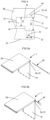
- FIGS 1a - 4 A first example not according to the invention is shown in FIGS 1a - 4 including a set 1 comprising a first panel 10, a second panel 20 and a mechanical locking device 30 for locking the first panel 10 to the second panel 20.
- the first panel 10 comprises a first edge surface 11 and a first panel surface 12.
- the second panel 20 comprises a second edge surface 21 and a second panel surface 22.
- the first edge surface 11 is facing the second panel surface 22 in a locked position of the first and the second panel 10, 20.
- the mechanical locking device 30 comprises a rod-shaped element 31 at the first edge surface 11 and an insertion groove 32 at the second panel surface 22.
- the mechanical locking device 30 further comprises an edge groove 33 at the second edge surface 21 and a flexible tongue 6 positioned in the edge groove 33.
- the rod-shaped element 31 comprises a recess 34.
- the rod-shaped element 31 is configured to be inserted into the insertion groove 32.
- the flexible tongue 6 is configured to cooperate with the recess 34 for a locking of the first panel 10 to the second panel 20 in a first direction which is perpendicular to the second panel surface 22.
- the first panel 10 and the second panel 20 are preferably panels for a furniture product and may be a part of a frame of a furniture product.
- the set 1 is preferably configured for locking the first panel 10 to the second panel 20 with the first panel surface 12 perpendicular or essentially perpendicular to the second panel surface 22.
- Figs. 1a-c disclose the set according to an aspect in an unassembled or dismantled state.
- Figs. 2a-b disclose the set according to an aspect in an assembled state.
- the set 1 may be assembled by displacing the first panel 10 relative the second panel 20 in a direction which is perpendicular to the second panel surface 22.
- the mechanical locking device 20 may be configured to automatically lock the first panel 10 to the second panel 20 when the rod-shaped element 31 is inserted into the insertion groove 32 and the first edge surface 11 is arranged against the second panel surface 22.
- the insertion groove 32 may be formed in the second panel surface 22 and in a core of the second panel 20.
- the second panel surface 22 may comprise a decorative layer and the insertion groove may extend though the decorative layer.
- the insertion groove may be formed by mechanical cutting, such as drilling.
- a first part of the flexible tongue 6 is configured to cooperate with the edge groove 33 and a second part is configured to cooperate with the recess 34 of the rod-shaped element 31.
- the second part may comprise a first bevel 65, which is configured to cooperate with the rod-shaped element 31 during assembling, and a second bevel 64, which is configured to cooperate with the recess 34 for the locking.
- the flexible tongue 6 may comprise a flexible material to enable compression and a displacement of the flexible tongue 6 in the edge groove 33 during assembling and dismantling.
- the flexible tongue 6 may comprise an element which is flexible to enable compression and a displacement of the flexible tongue 6 in the edge groove 33 during assembling and dismantling and another element which is less flexible in order to improve the locking strength.
- a part of a curved surface of an embodiment of the flexible tongue 6 may be configured to be displaced against a surface, such as a cylindrical surface, of the edge groove 33.
- the flexible tongue 6 may comprise a first essentially straight edge and a second edge which comprises a bendable part 61, preferably a first bendable part and a second bendable part.
- the first edge is preferably configured to cooperate with the recess 34 of the rod-shaped element 31.
- the flexible tongue preferably comprises a recess 63 at each of said bendable parts.
- a locking surface of the flexible tongue 6 may cooperate with a locking surface 62 of the recess 34 for the locking of the first panel 10 to the second panel 20.
- the first edge surface 11 may comprise two or more of said rod shaped element 31 and the second panel surface 22 may comprise two or more of said insertion groove 32, preferably arranged linearly, wherein each of the rod-shaped elements 31 is configured to be inserted into one of the insertion grooves 31.
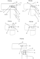
- FIG. 6a-e An aspect of the rod-shaped element 31 is shown in FIG. 6a-e which comprises an embodiment of the recess 34.
- the rod-shaped element 31 has a longitudinal shape with a length direction L, which is parallel to the first panel surface.
- a first crosscut of the rod-shaped element 31, in a plane parallel to the second panel surface 21 may have a circular shape, a rectangular shape, a star shape, an oval shape or a hexagon shape.
- the crosscut may be between the recess 34 and the edge 11.
- a locking of the first panel 10 to the second panel 20 in a second direction which is perpendicular to the first panel surface 12 may be obtained by cooperating locking surfaces between the insertion groove 32 and the rod-shaped element 31.
- a locking of the first panel to the second panel in a third direction which is perpendicular to the first direction and the second direction surface may be obtained by cooperating locking surfaces between the insertion groove 32 and the rod-shaped element 31.
- a second cross cut of the insertion groove 32, in a plane parallel to the second panel surface, preferably has a shape that matches a first cross cut of the rod-shaped element 31, in a plane parallel to the second panel surface.
- FIG. 4 is a cross cut along the insertion groove 32.
- the edge groove 33 extends from the second edge surface 21 of the second panel 20 inwards in the second panel 20.
- the edge groove 33 comprises an inner part 36 and an outer part 37.
- the inner part 36 of the edge groove has a first height H1.
- the outer part 37 of the edge groove has a second height H2.
- the height of the inner and outer part is seen in a direction that is parallel with the second end surface 21. Put in another way the height of the inner and outer part H1, H2 extend in the thickness of the second panel.
- the second height H2 of the outer part 37 is larger than the first height H1 of the inner part 36.
- the outer part 37 is located closer to the second edge surface than the inner part.
- the inner part 36 of the edge groove 33 may comprise a first surface, an opposite second surface and a bottom surface 35 extending between the first surface and the opposite second surface.
- the edge groove 33 is a bottom-ended groove comprising the bottom surface 35.
- the bottom surface 35 may be positioned at a distance from the insertion groove 32.
- the outer part 37 of the edge groove 33 may comprise a first surface, an opposite second surface and a bottom surface 38 extending between the first surface and the opposite second surface.
- the bottom surface 38 of the second part 37 comprises an opening 39 of the first part 36.
- the height H1 of the inner part 36 of the edge groove 33 is equal to or larger than a thickness of the flexible tongue 6.
- the rod shaped element 31 is connected to the first edge surface 11 at a first end 41 and comprise a rod surface 42 positioned between the recess 34 and a second end 43 of the rod-shaped element 31.
- the difference between the second height H2 of the outer part 37 of the edge groove 33 and the first height H1 of the inner part 36 of the edge groove 33 is equal to or larger than a length of the rod surface 41 between the recess 34 and the second end 43 of the rod-shaped element 31.
- the difference between the second height H2 of the outer part 37 of the edge groove 33 and the first height H1 of the inner part 36 of the edge groove 33 is or equal to or larger than a distance from an outer tip 66 of the flexible tongue 6 and a surface 67 of the flexible tongue 6 which cooperate with a surface of the inner part 36 of the edge groove 33.
- the difference between the second height H2 of the outer part 37 of the edge groove 33 and the first height H1 of the inner part 36 of the edge groove 33 is or equal to or larger than a distance from an outer tip of the flexible tongue and the locking surface 62 of the flexible tongue 6.
- the second height H2 of the outer part 37 of the edge groove 33 is 1,1 - 2,5 times larger than the first height H1 of the inner part 36. According to an aspect the second height H2 of the outer part 37 of the edge groove 33 is 1,1-1,5 times larger than the first height of the inner part.
- the flexible tongue 6 is arranged at the bottom surface 35 of the edge groove 33.
- the flexible tongue 6 is configured to be flexed inwards towards the bottom surface 35 to be completely positioned in the inner part 36 of the edge groove 33, as disclosed in FIGS. 6b,c,d .
- the flexible tongue 6, in an unflexed state is configured to be position partly in the outer part 37 and partly in the inner part 37 of the edge groove, as disclosed in FIG. 6a and e.
- the edge groove 33 is a longitudinal groove 33 that extends in a longitudinal direction of the second edge surface 22, as disclosed in FIGS. 1a,c and 2 a .
- second panel 20 comprise a third edge surface 23.
- edge groove 33 of the mechanical locking device 30 further is positioned at the third edge surface 23 as disclosed in FIG. 2a .
- the second panel 20 comprises a fourth edge surface 24.
- the edge groove 33 of the mechanical locking device 30 further is positioned at the fourth edge surface 24, as disclosed in FIG. 2a .
- the edge groove 33 extends from the third edge surface 23 to the fourth edge surface 24.
- the bendable part 61 of the flexible tongue 6 may be arranged at the bottom surface 35 of the edge groove 33.
- the flexible tongue 6 may be arranged at the bottom surface 35 of the edge groove 33.
- the flexible tongue may be arranged between the recess 34 and the bottom surface 35 of the edge groove in the locked position.
- a part of the flexible tongue 6 may be configured to be displaced against a surface of the edge groove 35, such as the first surface and/or the second surface.
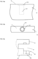
- the rod-shaped element 31 have a longitudinal shape with the length direction L which is parallel to the first panel surface 12.
- the rod-shaped element 31 comprises a first part 51 at the first end 41 and a second part 52 at the second end 43.
- the recess 34 is according to an aspect comprised in the second part 52.
- the first part 51 of the rod-shaped element 31 is configured to be inserted into an attachment groove 101 in the first edge surface 11, as disclosed in FIG. 1a , 6e 8a, b , 10 , 18a and 18b.
- FIG 18a shows a side view
- FIG 18b shows a top view of a part of an embodiment of the first panel 10.
- the second part 52 of the rod-shaped element 31 is according to an aspect configured to be inserted into the insertion groove 32.
- the rod shaped element 31 comprises a third part 53.
- the third part is located between the first and second part 51, 52.
- the third part 53 has according to an aspect an extension perpendicular to the length direction L that is larger than the extension of the attachment groove 101 in the first edge surface 11 in the corresponding direction.
- the third part is configured to restrict/define/limit the depth that the first part 51 could be inserted into the attachment groove 101.
- the depth of the attachment groove 101 does not define the position of the rod-shaped element 31 as long as the depth is larger than the first part 51. This opens up for that the attachment groove 101 could be manufactured with large tolerances without affecting the position of the rod-shaped element in the insertion groove 32. This will lower the production costs of the set.
- the third part 53 is integrated in the second part 52.
- the extension perpendicular to the length direction L of the third part 53 is equal to the extension of the second part 52 in the corresponding direction.
- the extension perpendicular to the length direction L of the third part 53 is larger than the extension D1 of the insertion groove 32 in the corresponding direction, such that the third part 53 is configured to restrict/define/limit the depth that the second part 52 could be inserted into the insertion groove 32.
- the length of the rod-shaped element 31 that could be inserted into the insertion groove 32 is limited and defined and lower the tolerances on the set 1 for positioning the rod-shaped element 31 in an intended locking position in view of the flexible tongue 6.
- the third part 53 comprise a flange 54 extending perpendicular to the length direction L.
- the flange 54 is a circumferential flange 54.
- the flange 54 is rectangular, square, triangular, or star shaped.
- the first edge surface 11 comprise a counterbore 102 corresponding to a shape of the third part 53.
- the second panel surface 22 of the second panel 20 may comprise a counterbore 102 corresponding to a shape of the third part 53.
- FIG. 18c shows a sideview of a part of the second panel 20.
- a depth of the counterbore 102 of the first edge surface 11 and/or the second panel surface 22 is equal to a thickness of the third part 53 in the length direction L.
- the first, second and third part 51, 52, 53 of the rod-shaped element 31 is made in one piece.
- the attachment groove 101 is a bottom-ended groove, such as a bottom ended drill hole, comprising a bottom surface which is positioned at a distance from the first edge surface 11 that is larger than a length of the first part 51 in the length direction L.
- the first part 51 of the rod-shaped element 31 is configured to be attached to the attachment groove 101 by friction.
- the rod-shaped element 31 is made from one or more of a wood based material, a polymer material, preferably with a reinforcement material, such as glass fibre or a metal.
- one or more of the first, second and third part 51, 52, 53 of the rod-shaped element 31 has a substantial circular shape.
- the rod-shaped element 31 may be configured to be glued in the attachment groove 101 in the first edge surface 11.
- the first part 51 of the rod-shaped element 31 comprises threads.
- the first part 51 of the rod-shaped element 31 comprise barbs 54, as disclosed in FIGS. 14 a, b .
- the rod-shaped element 31 is configured to be locked in the attachment groove 101 by a friction connection or by a mechanically connection, such as the threads or by a locking element, such as the barbs 54.
- the insertion groove 32 is according to an aspect a bottom-ended groove, such as a bottom ended drill hole, comprising a bottom surface 46, which is positioned at a distance from the edge groove 33.
- the insertion groove 32 may have a first part 43 on a first side of the edge groove 33 and a second part 44 on a second side of the edge groove 33, wherein the second part comprises the bottom surface 46 and side walls, wherein, in a locked position, the rod-shaped element 31 passes through the first part 43 of the insertion groove 32, through the edge groove 33 and into the second part 44 of the insertion groove 32.
- FIG. 6a shows a cross cut of the first panel 10 and the second panel 20 in a locked position, i.e. in an assembled position.
- the insertion groove according to an aspect extends from the second panel surface 22 to the edge groove 33.
- the rod-shaped element 31 may be configured to cooperate, for the locking in the second direction, with the side walls the second part 44 of the insertion groove 32.
- the rod-shaped element 31 may be configured to cooperate, in a locked position, with the bottom surface 46.
- the first part 43 of the insertion groove 32 may comprise side walls, wherein the rod-shaped element 31 may be configured to cooperate, for the locking in the second direction, with side walls of the first part 43.
- the sidewalls may comprise material of the core of the second panel 20.
- the second edge surface 21 may be essentially perpendicular to the second panel surface 22.
- the first panel 10 may be assembled by displacing the first panel 10 relative the second panel 20 in a direction which is perpendicular to the second panel surface 22.
- the mechanical locking device 30 is according to an aspect configured to automatically lock the first panel 10 to the second panel 20 when the rod-shaped element 31 is inserted into the insertion groove 32 and the first edge surface 11 is arranged against the second panel surface 22.
- the assembled first and second panel 10, 20 may be dismantled from each other. Put in another way, after the first and second panel 10, 20 has been assembled, they could be disassembled and separated. After they have been dismantled, they could be assembled together once again or assembled with another panel.
- the outer part 37 of the edge groove 33 is configured to receive a dismantling-rod 40.
- the dismantling-rod 40 is a rod shaped element that is insertable in the outer part 37 of the outer groove 33.
- the dismantling-rod has a longitudinal shape with a first end and a second end.
- the second end of the dismantling-rod 40 is adapted to be gripped by a user and the first end is adapted to be inserted into the edge groove 33.
- the cross sectional shape of the dismantling-rod 40 in a direction perpendicular to its longitudinal length is according to an aspect a polygon, for instance a trapezoid as disclosed in FIG. 6b and 6c .
- the cross sectional shape of the dismantling-rod 40 in a direction perpendicular to its longitudinal length is round, square, rectangular or triangular.
- the dismantling-rod 40 is flexible such that it is insertable into the edge groove 33 from the second edge surface 21. As the dismantling rod 40 is inserted from the second edge surface it flexes and bends such that it is positioned at the flexible tongue 6 and the recess 34. According to an aspect the dismantling-rod 40 is insertable into the edge groove 33 from the third edge surface 23. According to an aspect the dismantling-rod 40 is insertable into the edge groove 33 from the fourth edge surface 24.
- the user When a user should dismantle the first panel 10 from the second panel 20 and thus unlock the mechanical locking device 30, the user inserts the first end of the dismantling-rod 40 into the outer part 37 of the edge groove 33.
- the rod-shaped element 31 is configured to cooperate with the dismantling-rod 40 for flexing the flexible tongue 6 inwards in the edge groove 33.
- the dismantling-rod 40 When the dismantling-rod 40 is inserted into the outer part 37, it makes contact with the recess 34 of the rod-shaped element 31 and the flexible tongue 6.
- the shape of the dismantling-rod 40 corresponds to the shape of the recess 34 and when the dismantling-rod 40 is inserted further into the outer part 37 it will be positioned in the recess 34 and flex the flexible tongue 6 out of the recess 34 towards the inner part 36 of the edge groove 33, as disclosed in FIG. 6b .
- the rod-shaped element 31 When the flexible tongue 6 is flexed inwards in the edge groove 33, the rod-shaped element 31 is configured to be moveable in the insertion groove 32, as disclosed in FIG. 6b . According to an aspect and the orientation of the set, the rod-shaped element is moveable upwards or downwards, i.e. it is moveable outwards in the direction of the first edge surface 11. As the rod-shaped element 31 is moved the dismantling-rod 40 will after being moved a distance make contact with the inner wall of the outer part 37 of the edge groove 33, as disclosed in FIG. 6c . According to an aspect the distance that the rod-shaped element could be moved is the difference between the first height H1 of the inner part 36 and the second height H2 of the outer part 37.
- the flexible tongue 6 is positioned at the rod surface 42 of the rod-shaped element 31.
- the rod surface 42 restricts that the flexible tongue 6 is flexed outwards. According to an aspect the flexible tongue 6 flexes outward until it makes contact with the rod surface 42 of the rod-shaped element 31.
- the dismantling-rod 40 When the rod-shaped element 31 is moved upwards in the insertion groove 32 by the user and the flexible tongue 6 is not positioned in the recess 34, the dismantling-rod 40 is configured to be moved out of the edge groove 33. As the flexible tongue 6 is restricted from being flexed back into the recess 34 by the rod surface 42 in this position, the dismantling-rod 40 could be extracted from the outer part 37 without the mechanical locking device 30 returning to its locked position.
- the rod-shaped element 31 is configured to be moved further outwards and out of the insertion groove 32 to dismantle the first panel 10 from the second panel 20.
- the first panel 10 is now dismantled from the second panel 20.
- the flexible tongue 6 is flexed outwards towards the rod surface 42 of the rod-shaped element 31.
- a method for dismantling the set 1 from a locked position to a dismantled position by inserting the dismantling-rod 40 into the outer part 37 of the edge groove 33 and move the flexible tongue 6 out of the recess 34 of the rod-shaped element 31 by flexing the flexible tongue 6 inwards in the edge groove 33, move the rod-shaped element 31 and the dismantling-rod 40 outwards in the insertion groove 32, retract the dismantling-rod 40 out of the edge groove 33, and retract the rod-shaped element 31 further outwards and out of the insertion groove 32 to dismantle the first panel 10 from the second panel 20.
- the step of moving comprise moving the rod-shaped element 31 such a distance outwards that the flexible tongue 6 is unable to flex back into the recess 34.
- the first panel 10 can be assembled once again to the second panel 20 or to another panel comprising corresponding features.
- the second panel 20 can be assembled once again to the second panel 10 or to another panel comprising corresponding features.
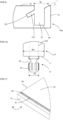
- the set 1 comprise a second panel 20a and the mechanical locking device 30 comprises a panel groove 133 at a second panel surface 22 of the second panel 20a.
- the panel groove 133 has the same function as the edge groove 33 disclosed above, however, according to this aspect the groove is positioned at the second panel surface 22 instead of at the second edge surface 21.
- the panel groove 133 extends at an angle ⁇ in the second panel 20a in view of the second panel surface 22. Put in another way, the panel groove 133 is made in the second panel 20a and is angled with an angle ⁇ in view of the second panel surface, as is disclosed in FIG. 9 .
- the flexible tongue 6, not disclosed in FIG. 9 is according to the invention positioned in the panel groove 133.
- the rod-shaped element 31 is positioned at the first edge surface 11 as disclosed above.
- the insertion groove 32 is, according to the invention, positioned at the second panel surface 22 and extends from the second panel surface 22 to the panel groove 133.
- the rod-shaped element 31 is configured to be inserted into the insertion groove 32 and the rod-shaped element 31 comprises a recess 34.
- the flexible tongue 6 is configured to cooperate with the recess 34 for a locking of the first panel 10 to the second panel 20a in a first direction which is perpendicular to the second panel surface 22.
- the angle ⁇ is between 10°-80° degrees. According to an aspect the angle ⁇ is between 10°-70° degrees. According to an aspect the angle is between 20-70 degrees. According to an aspect the angle ⁇ is between 15°-50° degrees. According to an aspect the angle ⁇ is between 25°-35° degrees. According to an aspect the second edge surface 21 of the second panel 20a is positioned at a distance from the panel groove 133.
- a width W1 of the panel groove 133 in the second panel surface 22 is smaller than a width W2 of the first edge surface 11. Put in another way the first edge surface 11 of the first panel 10 covers the panel groove 133 when the first panel 10 is locked towards the second panel 20a.
- the width W1 of the panel groove 133 in the second panel surface 22 is larger than a diameter D2, disclosed in FIG. 10 , of the rod-shaped element 133.
- the panel groove 133 is a bottom-ended groove, comprising a bottom surface 135 which is positioned at a distance from the insertion groove 32.
- the flexible tongue 6 is arranged at the bottom surface 135 of the panel groove 133.
- the flexible tongue 6 is configured to be flexed inwards towards the bottom surface 135 to be completely positioned in the panel groove 133.
- the flexible tongue 6, in an unflexed state is configured to be position partly in the panel groove 133 and partly in the insertion groove 32.
- the panel groove 133 is a longitudinal groove 133 that extends in a longitudinal direction of the second planar surface 22.
- the longitudinal direction of the longitudinal groove 133 is substantially parallel to the second edge surface 21.
- the second panel 20a comprise a third edge surface 23 and that the panel groove 133 of the mechanical locking device 30 further is positioned at the third edge surface 23.
- the second panel 20a comprise a fourth edge surface 24 and that the panel groove 133 of the mechanical locking device 30 further is positioned at the fourth edge surface 24.
- the panel groove 133 extends from the third edge surface 23 to the fourth edge surface 24.
- the insertion groove 32 is a bottom-ended groove, such as a bottom ended drill hole, comprising a bottom surface 46 which is positioned at a distance from the panel groove 133.
- the first edge surface 11 comprises two or more of said rod-shaped element 31 and the second panel surface 22 comprises two or more of said insertion groove 32 and one or more panel groove 133, preferably arranged linearly, wherein each of the rod-shaped elements 31 is configured to be inserted into one of the insertion grooves 32.
- the panel groove 133 is configured to receive the dismantling-rod 40.
- the rod-shaped element 31 When the dismantling rod 40 is received in the panel groove 133, the rod-shaped element 31 is configured to cooperate with the dismantling-rod 40 for flexing the flexible tongue 6 inwards in the panel groove 133. Thereafter, when the flexible tongue 6 is flexed inwards in the panel groove 133, the rod-shaped element 31 and the dismantling-rod 40 is configured to be moveable outwards in the insertion groove 32 and out of the insertion groove 32 to dismantle the first panel 10 from the second panel 20a. As the panel groove 133 extend from the second panel surface 22 the dismantling could be made in less steps than the dismantling method described above. This is due to that the insertion groove 32 and the panel groove 133 is positioned at one and the same surface, the second panel surface 22.
- the mechanical locking device 30 is configured to automatically lock the first panel 10 to the second panel 20a when the rod-shaped element 31 is inserted into the insertion groove 32 and the first edge surface 11 is arranged against the second panel surface 22.
- the flexible tongue 6 is arranged between the recess 34 of the rod-shaped element 31 and the bottom surface 135 of the panel groove 133 in the locked position.
- the second edge surface 21 is essentially perpendicular to the second panel surface 22.
- the rod-shaped element 31 according to the above could be connected to a second panel 20 comprising an edge groove 33 according to the above or to a panel groove 133 according to the above.
- the second panel 20, 20a comprise one or more edge grooves 33 and one or more panel grooves 133. According to an aspect the second panel 20, 20a is connected and locked to two or more first panels 10.
- the insertion groove 32 may be formed in the second panel surface 22 and in a core of the second panel 20.
- the second panel surface 22 may comprise a decorative layer and the insertion groove may extend though the decorative layer.
- the insertion groove may be formed by mechanical cutting, such as milling or sawing.
- An edge element such as an edge band, is according to an aspect attached to the second edge for covering the edge groove and for reinforcing the second edge 21.
- the edge element may be glued to the second edge or attached by a mechanical locking device, which may comprise a part that protrudes from the edge element and is configured to be inserted into the edge groove 53. The part may be attached to the edge groove by friction.
- the edge element is according to an aspect not covering the third and/or the fourth edge surface 23, 24 such that the dismantling-rod 40 could be inserted into the edge groove 33.
- the edge element is according to an aspect removable such that the dismantling-rod 40 could be inserted into the edge groove 33.
- the second panel may comprise two or more of said edge groove 5.
- the first panel 10 comprises two or more first edge surfaces 11 according to the above.
- one or more rod-shaped elements 31 can be positioned at two or more of the edges of the first panel 10, as disclosed in FIG. 15 and 17 .
- one or more rod-shaped elements 31 at one first edge surface 11 of one first panel 10 is positioned off-set in view of one or more rod-shaped elements at another first edge surface 11 of the first panel 10.
- one second panel could be connected to four first panels as disclosed in FIG. 15 .
- the second panel 20 comprises two second panel surfaces 22 and that one or more insertion grooves 32 extend from one of the second panel surface 22 and one or more insertion grooves 32 extend from the other second panel surface 22 to a common edge groove 33, as disclosed in FIG. 15 and 16 .
- a panel could be a combination of the first panel 10 and the second panel 20, 20a and comprise rod-shaped elements 31 at one edge and a panel groove 133 at a panel surface and/or an edge groove at another edge surface, as disclosed in FIG. 17 .
- the flexible tongue 6 may be according to the flexible tongue described and shown in FIGS 2A -2F and the related disclosure from page 6, line 15 to page 7, line 2, in WO2015/105449 .
- the core of the first panel 10 and/or of the second panel 20, 20a may be a wood-based core, preferably made of MDF, HDF, OSB, WPC, plywood or particleboard.
- the core may also be a plastic core comprising thermosetting plastic or thermoplastic e.g. vinyl, PVC, PU or PET.
- the plastic core may comprise fillers.
- the first panel 10 and/or the second panel 20, 20a may also be of solid wood.
- the first panel 10 and/or the second panel 20, 20a may be provided with a decorative layer, such as a foil or a veneer, on one or more surfaces.
- the set 1 are one of a bottom piece of a drawer, a frame and a back piece of a furniture product.
- the set of panels are resilient panels.
- the resilient panels may comprise a core comprising thermoplastic material.
- the thermoplastic material may be foamed.
- the thermoplastic material may comprise polyvinyl chloride (PVC), polyester, polypropylene (PP), polyethylene (PE), polystyrene (PS), polyurethane (PU), polyethylene terephthalate (PET), polyacrylate, methacrylate, polycarbonate, polyvinyl butyral, polybutylene terephthalate, or a combination thereof.
- the core may be formed of several layers.
- the aspects described above may comprise a decorative layer, such as a decorative foil comprising a thermoplastic material.
- the thermoplastic material of the decorative layer may be or comprise polyvinyl chloride (PVC), polyester, polypropylene (PP), polyethylene (PE), polystyrene (PS), polyurethane (PU), polyethylene terephthalate (PET), polyacrylate, methacrylate, polycarbonate, polyvinyl butyral, polybutylene terephthalate, or a combination thereof.
- the decorative foil is preferably printed, for example by direct printing, rotogravure, or digital printing.
- the decorative layer comprise melamine, a high pressure laminate (HPL) or a veneer.
- the aspects described above may comprise a wear layer such as a film or foil.
- the wear layer may comprise thermoplastic material.
- the thermoplastic material may be polyvinyl chloride (PVC), polyester, polypropylene (PP), polyethylene (PE), polystyrene (PS), polyurethane (PU), polyethylene terephthalate (PET), polyacrylate, methacrylate, polycarbonate, polyvinyl butyral, polybutylene terephthalate, or a combination thereof.
- the aspects described above may comprise a wood base core, such as HDF, MDF, plywood, particleboard, OSB or Masonite.
- a wood base core such as HDF, MDF, plywood, particleboard, OSB or Masonite.
Landscapes
- Engineering & Computer Science (AREA)
- General Engineering & Computer Science (AREA)
- Mechanical Engineering (AREA)
- Life Sciences & Earth Sciences (AREA)
- Wood Science & Technology (AREA)
- Connection Of Plates (AREA)
- Furniture Connections (AREA)
- Snaps, Bayonet Connections, Set Pins, And Snap Rings (AREA)
Applications Claiming Priority (2)
| Application Number | Priority Date | Filing Date | Title |
|---|---|---|---|
| SE1850447 | 2018-04-18 | ||
| PCT/SE2019/050363 WO2019203723A1 (en) | 2018-04-18 | 2019-04-17 | Set of panels with a mechanical locking device |
Publications (3)
| Publication Number | Publication Date |
|---|---|
| EP3781822A1 EP3781822A1 (en) | 2021-02-24 |
| EP3781822A4 EP3781822A4 (en) | 2022-01-19 |
| EP3781822B1 true EP3781822B1 (en) | 2024-08-21 |
Family
ID=68237143
Family Applications (1)
| Application Number | Title | Priority Date | Filing Date |
|---|---|---|---|
| EP19788121.2A Active EP3781822B1 (en) | 2018-04-18 | 2019-04-17 | Set of panels with a mechanical locking device |
Country Status (9)
| Country | Link |
|---|---|
| US (1) | US11076691B2 (https=) |
| EP (1) | EP3781822B1 (https=) |
| JP (1) | JP7305673B2 (https=) |
| CN (1) | CN112292537B (https=) |
| CA (1) | CA3096995A1 (https=) |
| EA (1) | EA202092389A1 (https=) |
| MY (1) | MY204226A (https=) |
| PL (1) | PL3781822T3 (https=) |
| WO (1) | WO2019203723A1 (https=) |
Families Citing this family (48)
| Publication number | Priority date | Publication date | Assignee | Title |
|---|---|---|---|---|
| UA109938C2 (uk) | 2011-05-06 | 2015-10-26 | Механічна фіксуюча система для будівельних панелей | |
| EA032305B1 (ru) | 2013-09-16 | 2019-05-31 | Велинге Инновейшн Аб | Собранное изделие |
| US9726210B2 (en) | 2013-09-16 | 2017-08-08 | Valinge Innovation Ab | Assembled product and a method of assembling the product |
| US9714672B2 (en) | 2014-01-10 | 2017-07-25 | Valinge Innovation Ab | Panels comprising a mechanical locking device and an assembled product comprising the panels |
| CR20160294A (es) | 2014-01-10 | 2016-09-27 | Valinge Innovoation Ab | Un panel para mobiliario |
| EP3140555B1 (en) | 2014-05-09 | 2021-03-17 | Välinge Innovation AB | Mechanical locking system for building panels |
| CA2969843C (en) | 2014-12-19 | 2023-09-26 | Valinge Innovation Ab | Panels comprising a mechanical locking device and an assembled product comprising the panels |
| EP3285620A4 (en) | 2015-04-21 | 2018-11-14 | Välinge Innovation AB | Panel with a slider |
| KR20170141223A (ko) | 2015-04-30 | 2017-12-22 | 뵈린게 이노베이션 에이비이 | 체결 디바이스를 갖는 패널 |
| LT3353429T (lt) | 2015-09-22 | 2024-03-25 | Välinge Innovation AB | Plokščių rinkinys, apimantis mechaninį fiksavimo įrenginį, ir minėtų plokščių išmontavimo būdas |
| MX2018006522A (es) | 2015-12-03 | 2018-11-29 | Vaelinge Innovation Ab | Paneles que comprenden un dispositivo de bloqueo mecanico y un producto ensamblado que comprende los paneles. |
| AU2017212222B2 (en) | 2016-01-26 | 2022-02-10 | Välinge Innovation AB | Panels comprising a mechanical locking device and an assembled product comprising the panels |
| KR20180109957A (ko) | 2016-02-04 | 2018-10-08 | 뵈린게 이노베이션 에이비이 | 조립된 제품을 위한 패널들의 세트 |
| EA037625B1 (ru) | 2016-02-15 | 2021-04-22 | Велинге Инновейшн Аб | Способ формирования панели для сборочного мебельного изделия |
| BR112019007619B1 (pt) | 2016-10-27 | 2023-02-14 | Välinge Innovation AB | Conjunto de painéis com um dispositivo de travamento mecânico |
| JP7201617B2 (ja) | 2017-05-15 | 2023-01-10 | ベーリンゲ、イノベイション、アクチボラグ | 組立品用のエレメント及び係止装置 |
| WO2019125291A1 (en) | 2017-12-22 | 2019-06-27 | Välinge Innovation AB | A set of panels, a method for assembly of the same and a locking device for a furniture product |
| CN111465773B (zh) | 2017-12-22 | 2021-11-02 | 瓦林格创新股份有限公司 | 镶板组、用于组装该镶板组的方法和用于家具产品的锁定装置 |
| HRP20231305T1 (hr) | 2018-03-23 | 2024-02-02 | Välinge Innovation AB | Skup ploča |
| EP3781823B1 (en) | 2018-04-18 | 2024-04-10 | Välinge Innovation AB | Set of panels with a mechanical locking device |
| EP3781824B1 (en) | 2018-04-18 | 2024-04-10 | Välinge Innovation AB | Set of panels with a mechanical locking device |
| WO2019203720A1 (en) | 2018-04-18 | 2019-10-24 | Välinge Innovation AB | Symmetric tongue & t-cross |
| US11614114B2 (en) | 2018-04-19 | 2023-03-28 | Valinge Innovation Ab | Panels for an assembled product |
| WO2020046194A1 (en) | 2018-08-30 | 2020-03-05 | Välinge Innovation AB | Set of panels with a mechanical locking device |
| FI3844407T3 (fi) | 2018-08-30 | 2024-05-08 | Vaelinge Innovation Ab | Paneelisarja mekaanisella lukituslaitteella |
| EP3730807A1 (en) | 2019-04-26 | 2020-10-28 | Välinge Innovation AB | Set of panels with a mechanical locking device |
| EP3834661A1 (en) | 2019-12-11 | 2021-06-16 | Välinge Innovation AB | Mechanical locking system for panels |
| CA3163335A1 (en) | 2019-12-19 | 2021-06-24 | Valinge Innovation Ab | Set of panels with a mechanical locking device |
| WO2021150162A1 (en) | 2020-01-22 | 2021-07-29 | Välinge Innovation AB | Set of panels with a mechanical locking device |
| EP3871559A1 (en) * | 2020-02-26 | 2021-09-01 | Välinge Innovation AB | Set of panels with a mechanical locking device |
| EP3871560A1 (en) | 2020-02-26 | 2021-09-01 | Välinge Innovation AB | Set of panels with a mechanical locking device |
| EP4162124A4 (en) | 2020-06-05 | 2024-07-31 | Välinge Innovation AB | Building panels comprising a locking device |
| US12038029B2 (en) * | 2020-07-17 | 2024-07-16 | Välinge Innovation AB | Mechanical locking system for panels |
| US20220090378A1 (en) * | 2020-09-18 | 2022-03-24 | Sharon Laing | Student Protection Screen |
| CN112360852A (zh) * | 2020-11-18 | 2021-02-12 | 金螳螂精装科技(苏州)有限公司 | 一种室内装修用用于模块式组合柜的侧板连接结构 |
| EP4258943B1 (en) | 2020-12-11 | 2026-01-28 | Välinge Innovation AB | Rail for cabinets |
| CA3205979A1 (en) | 2021-01-07 | 2022-07-14 | Valinge Innovation Ab | Wedge-shaped tongue insertion groove |
| CA3207233A1 (en) | 2021-01-19 | 2022-07-28 | Valinge Innovation Ab | A set of panels, a method for assembly of the same and a locking device for a furniture product |
| CA3206480A1 (en) | 2021-02-03 | 2022-08-11 | Valinge Innovation Ab | Building panels comprising a locking device |
| WO2022169399A1 (en) | 2021-02-08 | 2022-08-11 | Välinge Innovation AB | Furniture fitting assembly, mounting bracket and method for assembling furniture |
| CA3208921A1 (en) * | 2021-03-01 | 2022-09-09 | Valinge Innovation Ab | Mechanical connection arrangement for panels |
| WO2022184446A1 (en) | 2021-03-01 | 2022-09-09 | Välinge Innovation AB | Mechanical connection arrangement for panels |
| NL2028247B1 (en) * | 2021-05-19 | 2022-12-06 | J Van Klinken Holding B V | Interlockable wall reinforcement panel, wall reinforcement assembly and method for wall reinforcement |
| EP4352370A4 (en) | 2021-06-11 | 2025-04-09 | Välinge Innovation AB | A locking device comprising a spring and a locking pin and a set comprising furniture components and the locking device |
| CN113503294B (zh) * | 2021-07-24 | 2024-02-09 | 广东精诺五金实业有限公司 | 一种第一连接件、连接组件、连接系统及安装方法 |
| USD1060068S1 (en) * | 2022-05-05 | 2025-02-04 | Georg Rothbucher | Surveying instrument accessory |
| USD1060064S1 (en) * | 2022-07-26 | 2025-02-04 | Georg Rothbucher | Surveying instrument accessory |
| USD1044535S1 (en) * | 2022-07-26 | 2024-10-01 | Georg Rothbucher | Surveying instrument accessory |
Family Cites Families (302)
| Publication number | Priority date | Publication date | Assignee | Title |
|---|---|---|---|---|
| US291032A (en) | 1884-01-01 | Isaac g- | ||
| DE228872C (https=) | ||||
| US634581A (en) | 1898-11-21 | 1899-10-10 | Robert H Miller | Carpenter's square. |
| US701000A (en) | 1901-07-31 | 1902-05-27 | Carl F W Ahrens | File-cabinet. |
| US861911A (en) | 1905-11-04 | 1907-07-30 | William Stewart | Joint for articles of furniture or woodwork. |
| US881673A (en) | 1907-03-11 | 1908-03-10 | Arthur L Ellison | Wardrobe or safe. |
| US1534468A (en) | 1922-10-30 | 1925-04-21 | Jr John J Shea | Joint structure |
| US1533099A (en) | 1924-07-14 | 1925-04-14 | Robert E Carroll | Square-corner glue joint |
| GB245332A (en) | 1925-05-04 | 1926-01-07 | George Hugh Foster | An improved dowelled joint for woodwork and the like |
| US1800386A (en) | 1926-08-28 | 1931-04-14 | Andrew Hoffman Mfg Company | Display rail |
| US1800387A (en) | 1926-12-30 | 1931-04-14 | Andrew Hoffman Mfg Company | Article-supporting device |
| US1802245A (en) | 1930-08-26 | 1931-04-21 | Clarence L Foretich | Display stand and shelving |
| US1954242A (en) | 1932-07-28 | 1934-04-10 | Thomas E Heppenstall | Dovetail spring joint |
| US2360451A (en) | 1942-06-02 | 1944-10-17 | Stone Abraham | Collapsible clothing container |
| US2362904A (en) | 1943-01-20 | 1944-11-14 | Allied Purchasing Corp | Joint for demountable furniture |
| US2496184A (en) | 1946-06-11 | 1950-01-31 | Canon Paul L Von | Furniture drawer construction and method |
| US2681483A (en) | 1948-10-14 | 1954-06-22 | Morawetz Hugo | Dowel connection |
| DE1107910B (de) | 1957-03-26 | 1961-05-31 | Curt Weinert | Biegsamer Duebel |
| CH365507A (de) | 1958-11-17 | 1962-11-15 | Antonius Bus Johannes | Einrichtung zur Verbindung von senkrecht aufeinanderstehenden Wänden mit selbsttätiger Sperrung, insbesondere Möbelwänden |
| US3002630A (en) | 1960-05-24 | 1961-10-03 | Robert E Heisser | Toothbrush rack |
| US3195968A (en) | 1962-12-06 | 1965-07-20 | Lok Trim Corp | Knock-down furniture |
| DE1240638B (de) | 1963-03-07 | 1967-05-18 | Kueche | Zerlegbares Moebelstueck |
| AT260460B (de) | 1963-08-19 | 1968-03-11 | Trepatent As | Führung für Schubladen, Regalplatten od. dgl. |
| US3313054A (en) | 1965-06-09 | 1967-04-11 | Poster Products Inc | Display devices |
| IS831B6 (is) | 1965-10-28 | 1973-04-12 | Nordischer Maschinenbau Rud. BaaderNordischer Maschinenbau, Rud. Baader | Aðferð til þess að fjarlægja lifur úr fiskiTæki til að hausa hásskorinn fisk, þannig að vætubeinið verði eftir á fiskinum |
| US3410441A (en) | 1966-06-29 | 1968-11-12 | Jeff S. Rhyne | Container |
| US3347610A (en) | 1966-07-28 | 1967-10-17 | Pilliod Cabinet Company | Cabinet construction |
| DE1955922C3 (de) | 1969-11-06 | 1974-01-10 | Hefendehl, Hansfriedrich, 5893 Kierspe | Kastenmöbel aus Kunststoff |
| US3722704A (en) | 1970-07-23 | 1973-03-27 | Castelli Sas Anonima | Structural components for the composition of disassemblable pieces offurniture |
| JPS4817135U (https=) * | 1971-07-05 | 1973-02-26 | ||
| US3765465A (en) | 1972-01-05 | 1973-10-16 | Deutsch Fastener Corp | Retractable captive fastener |
| US3742807A (en) | 1972-02-03 | 1973-07-03 | D Manning | Leveling and locking pin |
| GB1398187A (en) | 1972-06-22 | 1975-06-18 | Schreiber Furniture | Kitchen cabinets |
| US3884002A (en) | 1973-03-15 | 1975-05-20 | American Store Equip | Partition system |
| BE810507A (fr) * | 1974-02-01 | 1974-05-29 | Moyen d'assemblage de deux parois d'armoire ou de meuble. | |
| DE2414104A1 (de) | 1974-03-23 | 1975-10-09 | Alfer Alu Fertigbau | Holzregal |
| DE2514357C3 (de) | 1974-04-02 | 1979-03-22 | Takeshi Tokio Shimizu | Beschlag zum verschwenkbaren Verbinden einer Möbelplatte mit einem feststehenden Möbelteil |
| US3885845A (en) | 1974-06-27 | 1975-05-27 | Hans Krieks | Knock-down furniture system |
| US3981118A (en) | 1974-10-17 | 1976-09-21 | The Goodyear Tire & Rubber Company | Clamping insert |
| CA1062321A (en) | 1976-05-12 | 1979-09-11 | I. T. W. Ltd. | Grommets for furniture connectors |
| DE2635237A1 (de) | 1976-08-05 | 1978-02-09 | Heinze Fa R | Moebelscharnier |
| JPS53113160U (https=) * | 1977-02-16 | 1978-09-08 | ||
| US4116510A (en) | 1977-03-03 | 1978-09-26 | Gte Automatic Electric Laboratories Incorporated | Chassis formed of sheet stock |
| US4099887A (en) | 1977-07-18 | 1978-07-11 | Einhard Mackenroth | Structural joints |
| US4222544A (en) | 1977-08-10 | 1980-09-16 | Kenneth Crowder | Picture rail apparatus |
| SE409603B (sv) | 1977-12-20 | 1979-08-27 | Stockum Design Ab | Forbindning |
| SE7809081L (sv) | 1978-08-29 | 1980-03-01 | Hafa Fabriks Ab | Anordning for uppberning av skap, speglar, hyllor och andra detaljer |
| US4211379A (en) | 1978-11-20 | 1980-07-08 | Morgan Myron B | Panelboard and mounting fixture combination |
| US4299067A (en) | 1979-10-30 | 1981-11-10 | J. C. Penney Company, Inc. | Partition connector system |
| US4308961A (en) | 1980-05-05 | 1982-01-05 | Kunce Thomas M | Article supporting structure |
| US4324517A (en) | 1980-06-16 | 1982-04-13 | Sps Technologies, Inc. | Panel fastener assembly with retainer ring |
| DE3047642A1 (de) | 1980-12-17 | 1982-10-28 | Arturo Salice S.p.A., 22060 Novedrate, Como | Verbindungsbeschlag |
| DE3103281C2 (de) | 1981-01-31 | 1984-05-10 | C + A Dick GmbH, 5275 Bergneustadt | Materialschrank |
| FR2501805A1 (fr) | 1981-03-10 | 1982-09-17 | Haeusler Roland | Nouveau systeme d'assemblage du genre a tenon et mortaise et articles mobiliers incorporant ledit systeme |
| FR2517187A1 (fr) | 1981-12-01 | 1983-06-03 | Beaux Dominique | Caisson demontable a usage de meuble |
| US4509648A (en) | 1982-07-26 | 1985-04-09 | The Stanley Works | Merchandising display system and components therefor |
| US4593734A (en) | 1983-09-26 | 1986-06-10 | M. Bosley Wright | Frame routing apparatus |
| US4629076A (en) | 1984-05-10 | 1986-12-16 | Amstore Corporation | Slatboard |
| GB2163825B (en) | 1984-08-30 | 1988-03-02 | Hettich Paul Gmbh & Co | Furniture connector |
| US4595105A (en) | 1984-09-12 | 1986-06-17 | Gold Kenneth S | Interlocking bookrack |
| US4750794A (en) | 1984-11-21 | 1988-06-14 | Bass Cabinet Manufacturing, Inc. | Slide-fitted article of furniture |
| US4597122A (en) | 1985-06-10 | 1986-07-01 | Hirsh Company | Free-standing drawer |
| US4615448A (en) | 1985-09-27 | 1986-10-07 | Masonite Corporation | Display panel |
| US4891897A (en) | 1985-12-12 | 1990-01-09 | Gieske Detlef J | Display panel |
| FR2597173B1 (fr) | 1986-04-10 | 1988-10-07 | Forschle Andre | Dispositif pour assembler et modifier facilement la composition d'un meuble en kit |
| GB8612597D0 (en) | 1986-05-23 | 1986-07-02 | George W R | Joint between members |
| FR2602013B1 (fr) | 1986-07-25 | 1988-12-30 | Kapikian Jean Claude | Systeme d'assemblage du type a tenon et mortaise aisement montable et demontable |
| US4815908A (en) | 1986-10-14 | 1989-03-28 | Avibank Mfg., Inc. | Captive panel fastener assembly |
| US4844266A (en) | 1987-07-16 | 1989-07-04 | Intercraft Industries Corporation | Display system |
| CA1297934C (en) | 1987-07-24 | 1992-03-24 | Craig Mengel | Method of and structure for the joining of substantially rigidparts together |
| US4886326A (en) | 1988-01-29 | 1989-12-12 | Tetrad Marketing/Sales Ltd. | Interlock system for ready to assemble furniture, and furniture incorporating such system |
| US4961295A (en) | 1988-03-14 | 1990-10-09 | Kosch Sr Paul | Metal slat and wall system utilizing same |
| US4817900A (en) | 1988-05-09 | 1989-04-04 | Gorrie Advertising Management Limited | Support device for use on a display wall |
| US4869564A (en) * | 1988-08-24 | 1989-09-26 | Nova Office Furniture, Inc. | Modular furniture |
| JPH0266308A (ja) | 1988-08-30 | 1990-03-06 | Kazuhiro Matsui | 組立具 |
| IT215989Z2 (it) | 1988-09-02 | 1991-03-26 | Cattarozzi Andrea | Contenitore modulare componibile e trasportabile manualmente, per la conservazione di sostanze, in special modo per uso alimentare |
| NL8802459A (nl) | 1988-10-07 | 1990-05-01 | Homburg Interieuren B V | Uitstalwand. |
| US5471804A (en) | 1988-11-21 | 1995-12-05 | Winter, Iv; Amos G. | Building system using prefabricated building panels and fastening components used therewith |
| US4944416A (en) | 1988-11-21 | 1990-07-31 | Petersen Robert J | Light-weight slot-wall display panel |
| US4909581A (en) | 1988-12-12 | 1990-03-20 | American Moulding & Millwork Company | Drawer construction |
| WO1990007066A2 (de) | 1988-12-13 | 1990-06-28 | Rudolf Tanner | Verbindungselement zum formschlüssigen verbinden |
| US5018323A (en) | 1989-05-12 | 1991-05-28 | Knud Clausen | Wall panel system |
| US5109993A (en) | 1989-10-31 | 1992-05-05 | Hutchison V James | Merchandise display system and merchandise holder therefor |
| US5138803A (en) | 1991-01-11 | 1992-08-18 | Commercial And Architectural Products, Inc. | Display panel assembly |
| US5121578A (en) | 1991-01-28 | 1992-06-16 | Holz Plastics, Inc. | Slat wall decorating system |
| WO1992017657A1 (en) | 1991-04-01 | 1992-10-15 | Walter Lindal | Wooden frame building construction |
| US5209556A (en) | 1991-04-01 | 1993-05-11 | Anderson Robert F | Drawer assembly |
| US5114265A (en) | 1991-04-15 | 1992-05-19 | Grisley Kenneth M | Interlocking routed joint |
| US5299509A (en) | 1991-07-29 | 1994-04-05 | Ballard Donald M | Connectors for shelves and bins |
| US5125518A (en) | 1991-08-12 | 1992-06-30 | Innovative Accessories | Interlocking hanging system |
| CH684284A5 (de) | 1991-09-03 | 1994-08-15 | Edgar Probst | Rückwandbeschlag. |
| US5212925A (en) | 1991-11-21 | 1993-05-25 | Mcclinton John | Wall corner composite, mold and method for producing glazed unit for such |
| US5360121A (en) | 1992-08-07 | 1994-11-01 | Commerical And Architectural Products, Inc. | Slotted display wall panel |
| JP2530326Y2 (ja) | 1992-08-24 | 1997-03-26 | 株式会社イトーキクレビオ | 家具等における部材の連結装置 |
| CH685276A5 (de) | 1992-11-25 | 1995-05-31 | Werner Schmidt | Bausatz zur Herstellung von Regalen, Schränken und Wohnwänden und Regale, Schränke und Wohnwände hergestellt mit diesem Bausatz. |
| ZA94676B (en) | 1993-02-03 | 1994-08-03 | Rohm & Haas | Reduction of microfoam in spray-applied waterborne composition. |
| US5423155A (en) | 1993-06-02 | 1995-06-13 | Darko Company, Inc. | Panel for resurfacing slat walls |
| US5499667A (en) | 1994-06-21 | 1996-03-19 | Nakanishi Construction Company | Drill/cutting bit, and method of making structural joint |
| US5527103A (en) | 1993-10-01 | 1996-06-18 | Pittman; Charles | Cabinet of improved design and construction |
| US5375802A (en) | 1993-11-17 | 1994-12-27 | Bill Branham Designs, Ltd. | Structure for fastening facing structural units |
| US5451102A (en) | 1994-01-13 | 1995-09-19 | Chuan; Yuan-Jung | Cabinet with connecting mechanism for two adjacent wall plate |
| US5499886A (en) | 1994-03-02 | 1996-03-19 | Sauder Woodworking Co. | Coupling assembly for furniture components |
| DE4410901A1 (de) | 1994-03-29 | 1995-10-05 | Licentia Gmbh | Kühlschrank mit Kühlgutablagen |
| US5507331A (en) | 1994-06-21 | 1996-04-16 | Nakanishi Construction Company | Drilling/cutting bit, and method of making joint |
| DE9417168U1 (de) | 1994-10-26 | 1995-02-09 | Seeland, Peter, 37130 Gleichen | Bausatz für ein Möbelstück |
| SE9500810D0 (sv) | 1995-03-07 | 1995-03-07 | Perstorp Flooring Ab | Golvplatta |
| DK9500332U3 (da) | 1995-08-29 | 1996-12-27 | Ikea Of Sweden Ab | Hjørnesamling mellem endepartierne af to bræddeagtige emner |
| US5658086A (en) | 1995-11-24 | 1997-08-19 | Brokaw; Paul E. | Furniture connector |
| US5775521A (en) | 1996-03-22 | 1998-07-07 | Custom Plastics, Inc. | Office organizer |
| CA2207533A1 (en) | 1996-06-12 | 1997-12-12 | David P. Thurston | Adjustable hanger system |
| US5950389A (en) | 1996-07-02 | 1999-09-14 | Porter; William H. | Splines for joining panels |
| US5810505A (en) | 1996-07-26 | 1998-09-22 | Kimball International, Inc. | Double threaded fastener system |
| GB2315988A (en) | 1996-08-07 | 1998-02-18 | Ultimate Systems Limited | Furniture with adjustable size panels |
| US5711115A (en) | 1996-10-30 | 1998-01-27 | Design Components, Inc. | Fireplace shelf and mantel support system |
| US6050426A (en) | 1997-03-19 | 2000-04-18 | Leurdijk; Jan B. | Storage track system |
| US5857304A (en) | 1997-04-07 | 1999-01-12 | Abex Display Systems | Slidable locking system for disengageable panels |
| CA2204301C (en) | 1997-05-02 | 2000-04-18 | Shang-Ming Lee | A connecting assembly for horizontal boards and wall boards of a cabinet |
| DE29714096U1 (de) | 1997-08-07 | 1998-12-03 | Dorth, Ursel, 51766 Engelskirchen | Verbindersystem |
| NO974666L (no) | 1997-10-09 | 1999-04-12 | New Ideas | Sammenf°yningsanordning for plateformete konstruksjonsdeler, samt m°belkonstruksjon |
| US5941026A (en) | 1998-01-20 | 1999-08-24 | Storewall Llc | Slatwall display system |
| DE19805538A1 (de) | 1998-02-03 | 1999-08-12 | Montana Innovations Corp | Verbindungsanordnung für in einem Winkel zueinander stehende flächige Körper oder Bauteile |
| AT406181B (de) | 1998-02-09 | 2000-03-27 | Blum Gmbh Julius | Befestigungsvorrichtung für die befestigung mehrerer möbelbeschläge an einem möbelteil |
| DE29924630U1 (de) | 1998-02-11 | 2004-05-13 | Ipeg Gmbh - Ingenieurdienstleistungen | Verbindungsvorrichtung für flächige Körper oder sonstige Bauteile |
| EP1055073A2 (de) | 1998-02-11 | 2000-11-29 | IPEG GmbH | Verbindungsvorrichtung für flächige körper oder sonstige bauteile |
| US6363645B1 (en) | 1998-02-25 | 2002-04-02 | Bruce A Hunter | Insert for display panels |
| US5944294A (en) | 1998-07-06 | 1999-08-31 | Baer; Thomas C. | Mounting device in form of C-clamp mounted space from a wall |
| DE29820031U1 (de) | 1998-11-10 | 1999-02-25 | Grant, Alasdair E., 33659 Bielefeld | Formschlüsselige Verbindungseinrichtung für Möbel bzw. Plattenelemente |
| US6349507B1 (en) | 1999-03-15 | 2002-02-26 | Spectra Products Corporation | Slat wall structure with profile for different shelf support brackets and the like |
| US6547086B1 (en) | 1999-03-25 | 2003-04-15 | Russell-William, Ltd. | Display wall panel |
| SE517478C2 (sv) | 1999-04-30 | 2002-06-11 | Valinge Aluminium Ab | Låssystem för mekanisk hofogning av golvskivor, golvskiva försedd med låssystemet samt metod för framställning av mekaniskt hopfogningsbara golvskivor |
| IT1307424B1 (it) | 1999-04-29 | 2001-11-06 | Costa S P A A | Metodo per la profilatura di listelli per parquet e macchinasquadratrice atta a realizzare tale metodo. |
| US7896571B1 (en) | 1999-06-30 | 2011-03-01 | Akzenta Paneele + Profile Gmbh | Panel and panel fastening system |
| DE29911462U1 (de) | 1999-07-02 | 1999-11-18 | Akzenta Paneele & Profile Gmbh | Befestigungssystem für Paneele |
| DE10001076C1 (de) | 2000-01-13 | 2001-10-04 | Huelsta Werke Huels Kg | Paneelelement |
| SE517183C2 (sv) | 2000-01-24 | 2002-04-23 | Valinge Aluminium Ab | Låssystem för mekanisk hopfogning av golvskivor, golvskiva försedd med låssystemet och metod för framställning av sådana golvskivor |
| MXPA02009326A (es) | 2000-03-24 | 2003-10-14 | Commercial And Architectural P | Sistema exhibidor de panel de mercancia. |
| US6413007B1 (en) | 2000-05-01 | 2002-07-02 | Sauder Woodworking Co. | Joint assembly |
| US6578498B1 (en) | 2000-06-06 | 2003-06-17 | Steelcase Development Corporation | Furniture accessory kit for portable computers and the like |
| HUP0400740A2 (en) | 2001-01-12 | 2004-07-28 | Valinge Aluminium Ab | Floorboard and locking system |
| US6675979B2 (en) | 2001-05-21 | 2004-01-13 | Gregory Albert Taylor | Furniture assembly system |
| DE20122553U1 (de) | 2001-08-10 | 2006-03-23 | Akzenta Paneele + Profile Gmbh | Paneel sowie Befestigungssystem für Paneele |
| DE10142508A1 (de) | 2001-08-30 | 2003-03-27 | Bsh Bosch Siemens Hausgeraete | Rastvorrichtung und mit dieser ausgestattete Küchenmaschine |
| SE525558C2 (sv) | 2001-09-20 | 2005-03-08 | Vaelinge Innovation Ab | System för bildande av en golvbeläggning, sats av golvskivor samt förfarande för tillverkning av två olika typer av golvskivor |
| DE60208218T2 (de) | 2001-09-26 | 2006-08-17 | Agostino Ferrari S.P.A. | Vorrichtung und verfahren zur lösbaren verbindung aneinanderstossender lasttragender teile und zugglied zur verwendung zur herstellung der vorrichtung |
| JP2003239921A (ja) | 2002-02-20 | 2003-08-27 | Takagaki Mokuzai Kogei Kk | ほぞとほぞ穴による接合構造 |
| UA81113C2 (en) | 2002-04-03 | 2007-12-10 | Valinge Innovation Ab | Floor board and method to make floor board |
| USD482552S1 (en) | 2002-04-03 | 2003-11-25 | Commercial And Architectural Products, Inc. | Insert for a display panel |
| US6772890B2 (en) | 2002-04-03 | 2004-08-10 | Commercial And Architectural Products, Inc. | Narrow groove display panel |
| AUPS265502A0 (en) | 2002-05-30 | 2002-06-20 | Ibj Resources Pty Ltd | Mounting system |
| WO2004009452A2 (en) | 2002-07-17 | 2004-01-29 | Device Works Company | Cable organization and hardware shelving system |
| US6827028B1 (en) | 2002-12-11 | 2004-12-07 | E. Pryor Callaway | Collapsible support |
| US7228977B2 (en) | 2003-06-16 | 2007-06-12 | Whirlpool Corporation | Workroom storage system |
| ATE471415T1 (de) | 2003-03-06 | 2010-07-15 | Vaelinge Innovation Ab | Fussbodensysteme und installationsverfahren |
| US7306299B2 (en) | 2003-03-07 | 2007-12-11 | Masterbrand Cabinets, Inc. | Semi-frameless cabinet and method for making the same |
| DE20304761U1 (de) | 2003-03-24 | 2004-04-08 | Kronotec Ag | Einrichtung zum Verbinden von Bauplatten, insbesondere Bodenpaneele |
| US6971614B2 (en) | 2003-07-11 | 2005-12-06 | Jifram Extrusions, Inc. | Slatwall hanger stabilizing chip |
| KR100975937B1 (ko) | 2003-09-30 | 2010-08-16 | 엘지전자 주식회사 | 냉장고용 도어바스켓 장착장치 |
| SE526596C2 (sv) | 2004-01-13 | 2005-10-11 | Vaelinge Innovation Ab | Flytande golv med mekanisk låssystem som möjliggör rörelse mellan golvskivorna |
| US20050166516A1 (en) | 2004-01-13 | 2005-08-04 | Valinge Aluminium Ab | Floor covering and locking systems |
| CH696889A5 (de) | 2004-03-23 | 2008-01-15 | Vifian Moebelwerkstaette Ag | Verriegelungselement und Verfahren zur Verriegelung von zwei Platten. |
| US20050247653A1 (en) | 2004-05-06 | 2005-11-10 | Dr. Brooks Innovations, L.L.C. | System for holding implements |
| US7641414B1 (en) | 2004-09-04 | 2010-01-05 | Joyce Jared L | Furniture and joint systems |
| DK1650375T4 (da) | 2004-10-22 | 2011-02-28 | Vaelinge Innovation Ab | Sæt af gulvpaneler |
| US7841144B2 (en) | 2005-03-30 | 2010-11-30 | Valinge Innovation Ab | Mechanical locking system for panels and method of installing same |
| US7454875B2 (en) | 2004-10-22 | 2008-11-25 | Valinge Aluminium Ab | Mechanical locking system for floor panels |
| DE202004017486U1 (de) | 2004-11-11 | 2006-04-13 | Vietmeyer, Adolf | Rahmen eines Schrankes, eines Regales o.dgl. |
| GB0426634D0 (en) | 2004-12-03 | 2005-01-05 | Abbott Ooo | Display panel and display system |
| DE202004019882U1 (de) | 2004-12-20 | 2006-04-27 | Fritz Egger Gmbh & Co. | Möbelteile mit Verbindungsmitteln |
| US7686172B2 (en) | 2005-02-14 | 2010-03-30 | Whirlpool Corporation | Storage bin |
| GB2423332B (en) | 2005-02-17 | 2009-05-27 | Arctium As | Connecting device |
| JP2008534878A (ja) | 2005-03-29 | 2008-08-28 | ヘンダーソン,ピエター,マーティン | コンポーネントを連接するための締結具とこれを具現するアッセンブリ |
| US20060273085A1 (en) | 2005-05-18 | 2006-12-07 | Casto Daniel A | Joint for connecting workpieces |
| US20090014401A1 (en) | 2005-05-24 | 2009-01-15 | Windquest Companies, Inc. | Slotwall mounting assembly |
| SE529076C2 (sv) | 2005-07-11 | 2007-04-24 | Pergo Europ Ab | En fog till paneler |
| EP1913214A1 (en) | 2005-07-28 | 2008-04-23 | Granbay Holdings PTY Ltd. | Interlocking members |
| CH698988B1 (de) | 2005-08-27 | 2009-12-31 | Lindauer Gmbh | Plattenförmiges Vollholzelement und Abdeckung |
| DE202005019986U1 (de) | 2005-12-20 | 2006-02-23 | fif Möbel Vertriebs GmbH | Bausatz für ein Kastenmöbel |
| SE530653C2 (sv) | 2006-01-12 | 2008-07-29 | Vaelinge Innovation Ab | Fuktsäker golvskiva samt golv med ett elastiskt ytskikt omfattande ett dekorativt spår |
| DE102006011887A1 (de) | 2006-01-13 | 2007-07-19 | Akzenta Paneele + Profile Gmbh | Sperrelement, Paneel mit separatem Sperrelement, Verfahren zur Installation eines Paneelbelags aus Paneelen mit Sperrelementen sowie Verfahren und Vorrichtung zur Vormontage eines Sperrelements an einem Paneel |
| DE102006006124A1 (de) | 2006-02-10 | 2007-08-23 | Flooring Technologies Ltd. | Einrichtung zum Verriegeln zweier Bauplatten |
| SE533410C2 (sv) | 2006-07-11 | 2010-09-14 | Vaelinge Innovation Ab | Golvpaneler med mekaniska låssystem med en flexibel och förskjutbar tunga samt tunga därför |
| US7861482B2 (en) | 2006-07-14 | 2011-01-04 | Valinge Innovation Ab | Locking system comprising a combination lock for panels |
| DE102006037614B3 (de) | 2006-08-10 | 2007-12-20 | Guido Schulte | Fußbodenbelag und Verlegeverfahren |
| US20080042532A1 (en) | 2006-08-16 | 2008-02-21 | Crabtree Phillip C | Cabinet system and method of assembling the same |
| US7614350B2 (en) | 2006-10-05 | 2009-11-10 | Haworth, Inc. | Wall-mounted shelf unit |
| DE502007001064D1 (de) | 2006-11-14 | 2009-08-27 | Spichtig Ag | Ablage- und Sortiervorrichtung |
| SE531111C2 (sv) | 2006-12-08 | 2008-12-23 | Vaelinge Innovation Ab | Mekanisk låsning av golvpaneler |
| GB2445954A (en) | 2007-01-23 | 2008-07-30 | Touac Internat Ltd | A panel joining fastener |
| ES2317821T3 (es) | 2007-05-08 | 2015-10-15 | Franz Baur | Medios y método de unión para establecer una unión de un primer componente a un segundo componente |
| SE533028C2 (sv) | 2007-06-05 | 2010-06-15 | Rickard Olsson | Lådkonstruktion och monteringsmetod |
| US7818939B2 (en) | 2007-06-05 | 2010-10-26 | Irvin Bearinger | Snap lock joint |
| US8220217B2 (en) | 2007-07-20 | 2012-07-17 | Innovaris Ag | Flooring system |
| US7726088B2 (en) | 2007-07-20 | 2010-06-01 | Moritz Andre Muehlebach | Flooring system |
| CN101099618A (zh) | 2007-07-26 | 2008-01-09 | 刘瑞东 | 榫卯式家具 |
| DE102007043308B4 (de) | 2007-09-11 | 2009-12-03 | Flooring Technologies Ltd. | Einrichtung zur Verbindung und Verriegelung zweier Bauplatten, insbesondere Fussbodenpaneele |
| US8146754B2 (en) | 2007-12-07 | 2012-04-03 | Red Star Traders, Llc | Storage and organization system |
| US8505257B2 (en) | 2008-01-31 | 2013-08-13 | Valinge Innovation Ab | Mechanical locking of floor panels |
| CA2623707A1 (en) | 2008-03-07 | 2009-09-07 | Pierre Trudel | Tongue and groove profile to ease desassembly of floorboards |
| GB0808252D0 (en) | 2008-05-07 | 2008-06-11 | Self Energising Coupling Compa | Latch mechanism |
| US7717278B2 (en) | 2008-07-07 | 2010-05-18 | Jui-Chien Kao | Tool suspension device |
| DE102008035293A1 (de) | 2008-07-29 | 2010-02-04 | Gronbach Forschungs- Und Entwicklungs Gmbh & Co. Kg | Einrichtungsgegenstand für Wohnungen oder Möbel |
| US8220648B2 (en) | 2008-08-01 | 2012-07-17 | Southern Imperial, Inc. | Folded slatwall inserts |
| DE202008011589U1 (de) | 2008-09-01 | 2008-11-27 | Akzenta Paneele + Profile Gmbh | Fußbodenpaneel aus Kunststoff mit mechanischen Verriegelungskanten |
| WO2010042182A1 (en) | 2008-10-08 | 2010-04-15 | Armstrong World Industries, Inc. | Flooring panel with first and second decorative surfaces |
| US20100104354A1 (en) * | 2008-10-29 | 2010-04-29 | Lamar Spalding | Pinned Lock Joint |
| BE1018389A3 (nl) * | 2008-12-17 | 2010-10-05 | Unilin Bvba | Samengesteld element, meerlagige plaat en paneelvormig element voor het vormen van zulk samengesteld element. |
| US7998549B2 (en) | 2009-01-08 | 2011-08-16 | Thermwood Corporation | Structure and method of assembly thereof |
| BE1018627A5 (nl) | 2009-01-16 | 2011-05-03 | Flooring Ind Ltd Sarl | Vloerpaneel. |
| CA2951650C (en) | 2009-01-30 | 2019-03-12 | Valinge Innovation Ab | Mechanical lockings of floor panels and a tongue blank |
| US8464408B2 (en) | 2009-06-03 | 2013-06-18 | Tracy Leigh Hazzard | Hardware for furniture assembly |
| NL2003019C2 (nl) | 2009-06-12 | 2010-12-15 | 4Sight Innovation Bv | Vloerpaneel en vloerbedekking bestaande uit meerdere van dergelijke vloerpanelen. |
| DE102009034902B4 (de) | 2009-07-27 | 2015-10-01 | Guido Schulte | Belag aus mechanisch miteinander verbindbaren Paneelen |
| CA2764965C (en) | 2009-07-31 | 2017-10-03 | Vaelinge Innovation Ab | Methods and arrangements relating to edge machining of building panels |
| US8365499B2 (en) | 2009-09-04 | 2013-02-05 | Valinge Innovation Ab | Resilient floor |
| DE102009041142B4 (de) | 2009-09-14 | 2015-11-05 | System 180 Gmbh | Anordnung mit Wandelementen, Bausatz für eine Anordnung sowie Wandelement für ein Möbel |
| DE202009012917U1 (de) | 2009-09-26 | 2011-02-10 | Fehre, Jürgen | Schubkasten |
| EP2333353A3 (en) | 2009-12-02 | 2012-07-25 | Lolli, Paride | Longitudinal sliding joint |
| EP4092213B1 (en) | 2010-01-11 | 2023-12-13 | Välinge Innovation AB | Floor covering with interlocking design |
| CN102695838B (zh) | 2010-01-12 | 2016-01-20 | 瓦林格创新股份有限公司 | 地板镶板的机械锁定系统 |
| DE102010004717A1 (de) | 2010-01-15 | 2011-07-21 | Pergo (Europe) Ab | Set aus Paneelen umfassend Halteprofile mit einem separaten Clip sowie Verfahren zum Einbringen des Clips |
| US8234830B2 (en) | 2010-02-04 | 2012-08-07 | Välinge Innovations AB | Mechanical locking system for floor panels |
| WO2011096879A1 (en) | 2010-02-04 | 2011-08-11 | Välinge Innovation AB | Mechanical locking system for floor panels and a tongue therefore |
| GB201002535D0 (en) | 2010-02-15 | 2010-03-31 | Fgb Ltd | Improvements relating to cabinets |
| BE1019361A5 (nl) | 2010-06-03 | 2012-06-05 | Unilin Bvba | Samengesteld element. |
| EP2575542B1 (en) | 2010-06-03 | 2021-03-10 | Unilin, BV | Composed element and corner connection applied herewith |
| WO2011160173A1 (en) | 2010-06-22 | 2011-12-29 | Joinlock Pty Ltd | Key and keyway connectors |
| US20120009383A1 (en) | 2010-07-09 | 2012-01-12 | Michael Hardesty | Method for Joining Workpieces Together and Product Made Thereby |
| US8911037B2 (en) | 2010-12-14 | 2014-12-16 | Tenn-Tex Plastics, Inc. | Brackets and associated components for drawer and tray slides in cabinetry |
| GB201100622D0 (en) | 2011-01-14 | 2011-03-02 | Phillips Sean | Article of furniture |
| IT1403925B1 (it) | 2011-02-09 | 2013-11-08 | O M M S A S Dell Ing Roberto Mariani & C | Dispositivo di giunzione di pannelli di un mobile. |
| US8864407B1 (en) | 2011-03-17 | 2014-10-21 | Petter Sorum | Locking joint for joining structural members |
| UA109938C2 (uk) * | 2011-05-06 | 2015-10-26 | Механічна фіксуюча система для будівельних панелей | |
| EP2526819A1 (en) | 2011-05-25 | 2012-11-28 | Steen Sauer | Assembling of drawer |
| US8602227B1 (en) | 2011-06-08 | 2013-12-10 | Megawall, Inc. | Slatwall panel |
| CH705082A2 (de) | 2011-06-14 | 2012-12-14 | Denz Ag | Verriegelungselement für Schränke und Tablare und eine Verriegelungsanordnung an Schränken und Tablaren. |
| BE1020044A5 (nl) | 2011-06-29 | 2013-04-02 | Unilin Bvba | Lade, ladeconstructie en werkwijze voor het vervaardigen van een lade. |
| EP2732109B1 (en) | 2011-07-11 | 2019-08-28 | Ceraloc Innovation AB | Mechanical locking system for floor panels |
| US9725912B2 (en) | 2011-07-11 | 2017-08-08 | Ceraloc Innovation Ab | Mechanical locking system for floor panels |
| MY164223A (en) | 2011-08-15 | 2017-11-30 | Ceraloc Innovation Ab | Mechanical locking system for floor panels |
| US20130048632A1 (en) | 2011-08-29 | 2013-02-28 | Yi Hsiang Chen | Quick-disconnect storage box modular structure |
| KR101147274B1 (ko) | 2011-11-09 | 2012-05-18 | 주식회사 한샘 | 가구용 패널의 제조방법 |
| BE1020453A3 (nl) | 2011-12-01 | 2013-10-01 | Unilin Bvba | Meubel en werkwijze voor het vervaardigen van meubels. |
| DE102011057018B4 (de) | 2011-12-23 | 2017-11-02 | Guido Schulte | Leimloser Korpus |
| DE102012105219A1 (de) | 2011-12-23 | 2013-06-27 | Guido Schulte | Leimloser Korpus |
| US20150034522A1 (en) | 2012-01-27 | 2015-02-05 | Dic Corporation | Coating material composition, can coating material containing the same, and metal material with coating formed by the can coating material for can interior surfaces |
| BE1020495A4 (nl) | 2012-02-08 | 2013-11-05 | Unilin Bvba | Samengesteld element en hoekverbinding hierbij toegepast. |
| US8596013B2 (en) | 2012-04-04 | 2013-12-03 | Valinge Innovation Ab | Building panel with a mechanical locking system |
| US9216541B2 (en) | 2012-04-04 | 2015-12-22 | Valinge Innovation Ab | Method for producing a mechanical locking system for building panels |
| ITBO20120281A1 (it) | 2012-05-23 | 2013-11-24 | Biesse Spa | Macchina per la bordatura di pannelli di legno o simili |
| BE1020722A3 (nl) | 2012-06-01 | 2014-04-01 | Unilin Bvba | Paneel voor het vormen van een vloerbekleding en werkwijze voor het vervaardigen van dergelijke panelen. |
| US9510518B2 (en) | 2012-07-11 | 2016-12-06 | Dimitri Shein | Sheet metal structure |
| DE102012013807A1 (de) | 2012-07-12 | 2014-05-15 | Kolbus Gmbh & Co. Kg | Vorrichtung zum Nuten von Pappenzuschnitten |
| US9763528B2 (en) | 2012-09-27 | 2017-09-19 | Whirlpool Corporation | Track for slotted wall system |
| KR101423546B1 (ko) | 2012-09-28 | 2014-07-25 | 주식회사 한샘 | 엣지시트가 접착된 가구용 패널 및 그 제조방법 |
| US9771964B2 (en) | 2012-11-06 | 2017-09-26 | Inter Ikea Systems B.V. | Fastening device, fastening system and furniture assembly |
| DE102013100352A1 (de) | 2013-01-14 | 2014-07-17 | Guido Schulte | Leimloser Plattenverbund sowie Verfahren zum leimlosen Verbinden zweier Plattenelemente |
| WO2014121410A1 (es) | 2013-02-05 | 2014-08-14 | Luis Antonio Lira Campino | Celda de construcción modular prefabricada |
| US20140294498A1 (en) | 2013-04-02 | 2014-10-02 | William Robert Logan | Furniture component joining system |
| WO2015015603A1 (ja) | 2013-07-31 | 2015-02-05 | 株式会社白井産業 | 部材の結合構造及びこれを備えた組立構造物 |
| CN203424576U (zh) | 2013-08-21 | 2014-02-12 | 陈世威 | 板材组合自动锁及组合式柜体 |
| US9955781B2 (en) | 2013-08-30 | 2018-05-01 | Ikea Supply Ag | Furniture module |
| US9726210B2 (en) | 2013-09-16 | 2017-08-08 | Valinge Innovation Ab | Assembled product and a method of assembling the product |
| EA032305B1 (ru) | 2013-09-16 | 2019-05-31 | Велинге Инновейшн Аб | Собранное изделие |
| GB2520927A (en) | 2013-11-13 | 2015-06-10 | Hassan Fouladi | Panel for building a structure |
| US9700157B2 (en) | 2013-12-20 | 2017-07-11 | Andreas Gesswein | Suspension device |
| CR20160294A (es) | 2014-01-10 | 2016-09-27 | Valinge Innovoation Ab | Un panel para mobiliario |
| EP3594513A1 (en) | 2014-01-10 | 2020-01-15 | Välinge Innovation AB | Panels comprising a mechanical locking device and an assembled product comprising the panels |
| US9714672B2 (en) | 2014-01-10 | 2017-07-25 | Valinge Innovation Ab | Panels comprising a mechanical locking device and an assembled product comprising the panels |
| MY179793A (en) | 2014-01-10 | 2020-11-14 | Valinge Innovation Ab | An assembled product and a method of assembling the product |
| FR3019862B1 (fr) | 2014-04-11 | 2017-07-21 | Elsa Profil | Systeme d'assemblage de panneaux suivant un diedre pour realiser un meuble et meuble ainsi realise |
| EP3140555B1 (en) * | 2014-05-09 | 2021-03-17 | Välinge Innovation AB | Mechanical locking system for building panels |
| UA119565C2 (uk) | 2014-07-11 | 2019-07-10 | Велінге Інновейшн Аб | Панель з напрямною |
| DE102014110124A1 (de) | 2014-07-18 | 2016-01-21 | Guido Schulte | Nut- und Federeckverbindung von zwei Bauelementen unter Eingliederung einer zusätzlichen Nut- und Federsteckverbindung |
| US9938066B2 (en) | 2014-09-12 | 2018-04-10 | Sonoco Development, Inc. | Temperature controlled pallet shipper |
| EP3031998B1 (de) | 2014-12-08 | 2017-09-27 | Innovations4Flooring Holding N.V. | Paneel mit einem hakenförmigen Verriegelungssystem |
| CA2969843C (en) | 2014-12-19 | 2023-09-26 | Valinge Innovation Ab | Panels comprising a mechanical locking device and an assembled product comprising the panels |
| CA2876325A1 (en) | 2014-12-31 | 2016-06-30 | Fitneff Inc. | Clip and rail attachment system |
| US10378570B2 (en) | 2015-01-07 | 2019-08-13 | Fyrn | Securing pin for securing structural members |
| EP3285620A4 (en) | 2015-04-21 | 2018-11-14 | Välinge Innovation AB | Panel with a slider |
| KR20170141223A (ko) * | 2015-04-30 | 2017-12-22 | 뵈린게 이노베이션 에이비이 | 체결 디바이스를 갖는 패널 |
| WO2016187533A1 (en) | 2015-05-20 | 2016-11-24 | Richard Stack | Modular cabinet hidden clamping system |
| LT3353429T (lt) | 2015-09-22 | 2024-03-25 | Välinge Innovation AB | Plokščių rinkinys, apimantis mechaninį fiksavimo įrenginį, ir minėtų plokščių išmontavimo būdas |
| MX2018006522A (es) | 2015-12-03 | 2018-11-29 | Vaelinge Innovation Ab | Paneles que comprenden un dispositivo de bloqueo mecanico y un producto ensamblado que comprende los paneles. |
| AU2017212222B2 (en) | 2016-01-26 | 2022-02-10 | Välinge Innovation AB | Panels comprising a mechanical locking device and an assembled product comprising the panels |
| KR20180109957A (ko) | 2016-02-04 | 2018-10-08 | 뵈린게 이노베이션 에이비이 | 조립된 제품을 위한 패널들의 세트 |
| EP3413752B1 (en) | 2016-02-09 | 2020-11-25 | Välinge Innovation AB | A set of three panel-shaped elements |
| KR20180110027A (ko) | 2016-02-09 | 2018-10-08 | 뵈린게 이노베이션 에이비이 | 분해 홈을 제공하기 위한 요소 및 방법 |
| EA037625B1 (ru) | 2016-02-15 | 2021-04-22 | Велинге Инновейшн Аб | Способ формирования панели для сборочного мебельного изделия |
| WO2018004435A1 (en) | 2016-06-30 | 2018-01-04 | Välinge Innovation AB | Device for inserting a tongue |
| BR112019007619B1 (pt) | 2016-10-27 | 2023-02-14 | Välinge Innovation AB | Conjunto de painéis com um dispositivo de travamento mecânico |
| DE202017101856U1 (de) | 2017-03-30 | 2017-04-27 | Häfele Berlin Gmbh & Co Kg | Rückwand-Einsteckkeil |
| JP7201617B2 (ja) | 2017-05-15 | 2023-01-10 | ベーリンゲ、イノベイション、アクチボラグ | 組立品用のエレメント及び係止装置 |
| WO2019125291A1 (en) | 2017-12-22 | 2019-06-27 | Välinge Innovation AB | A set of panels, a method for assembly of the same and a locking device for a furniture product |
| CN111465773B (zh) | 2017-12-22 | 2021-11-02 | 瓦林格创新股份有限公司 | 镶板组、用于组装该镶板组的方法和用于家具产品的锁定装置 |
| HRP20231305T1 (hr) | 2018-03-23 | 2024-02-02 | Välinge Innovation AB | Skup ploča |
| EP3781823B1 (en) | 2018-04-18 | 2024-04-10 | Välinge Innovation AB | Set of panels with a mechanical locking device |
| EP3781824B1 (en) | 2018-04-18 | 2024-04-10 | Välinge Innovation AB | Set of panels with a mechanical locking device |
| WO2019203720A1 (en) | 2018-04-18 | 2019-10-24 | Välinge Innovation AB | Symmetric tongue & t-cross |
| US11614114B2 (en) | 2018-04-19 | 2023-03-28 | Valinge Innovation Ab | Panels for an assembled product |
| FI3844407T3 (fi) | 2018-08-30 | 2024-05-08 | Vaelinge Innovation Ab | Paneelisarja mekaanisella lukituslaitteella |
| WO2020046194A1 (en) | 2018-08-30 | 2020-03-05 | Välinge Innovation AB | Set of panels with a mechanical locking device |
| EP3730807A1 (en) | 2019-04-26 | 2020-10-28 | Välinge Innovation AB | Set of panels with a mechanical locking device |
-
2019
- 2019-04-17 EP EP19788121.2A patent/EP3781822B1/en active Active
- 2019-04-17 US US16/386,824 patent/US11076691B2/en active Active
- 2019-04-17 CA CA3096995A patent/CA3096995A1/en active Pending
- 2019-04-17 WO PCT/SE2019/050363 patent/WO2019203723A1/en not_active Ceased
- 2019-04-17 PL PL19788121.2T patent/PL3781822T3/pl unknown
- 2019-04-17 EA EA202092389A patent/EA202092389A1/ru unknown
- 2019-04-17 CN CN201980038399.3A patent/CN112292537B/zh active Active
- 2019-04-17 JP JP2020555894A patent/JP7305673B2/ja active Active
- 2019-04-17 MY MYPI2020005263A patent/MY204226A/en unknown
Also Published As
| Publication number | Publication date |
|---|---|
| EA202092389A1 (ru) | 2021-01-27 |
| WO2019203723A1 (en) | 2019-10-24 |
| EP3781822A4 (en) | 2022-01-19 |
| US20190320793A1 (en) | 2019-10-24 |
| BR112020020666A2 (pt) | 2021-01-12 |
| PL3781822T3 (pl) | 2024-11-18 |
| JP7305673B2 (ja) | 2023-07-10 |
| JP2021521387A (ja) | 2021-08-26 |
| US11076691B2 (en) | 2021-08-03 |
| EP3781822A1 (en) | 2021-02-24 |
| MY204226A (en) | 2024-08-16 |
| CN112292537B (zh) | 2022-11-29 |
| CA3096995A1 (en) | 2019-10-24 |
| CN112292537A (zh) | 2021-01-29 |
Similar Documents
| Publication | Publication Date | Title |
|---|---|---|
| EP3781822B1 (en) | Set of panels with a mechanical locking device | |
| EP3781823B1 (en) | Set of panels with a mechanical locking device | |
| EP3781824B1 (en) | Set of panels with a mechanical locking device | |
| EP4110135B1 (en) | Set of panels with a mechanical locking device | |
| US12408748B2 (en) | Set of panels with a mechanical locking device | |
| AU2019330606B2 (en) | Set of panels with a mechanical locking device | |
| EP4110134B1 (en) | Set of panels with a mechanical locking device | |
| US20240229844A9 (en) | Set of panels with a mechanical locking device | |
| EP3167198B1 (en) | Panel with a slider | |
| US20260123745A1 (en) | Set of panels with a mechanical locking device | |
| EA040753B1 (ru) | Набор панелей с механическим блокирующим устройством |
Legal Events
| Date | Code | Title | Description |
|---|---|---|---|
| STAA | Information on the status of an ep patent application or granted ep patent |
Free format text: STATUS: THE INTERNATIONAL PUBLICATION HAS BEEN MADE |
|
| PUAI | Public reference made under article 153(3) epc to a published international application that has entered the european phase |
Free format text: ORIGINAL CODE: 0009012 |
|
| STAA | Information on the status of an ep patent application or granted ep patent |
Free format text: STATUS: REQUEST FOR EXAMINATION WAS MADE |
|
| 17P | Request for examination filed |
Effective date: 20201118 |
|
| AK | Designated contracting states |
Kind code of ref document: A1 Designated state(s): AL AT BE BG CH CY CZ DE DK EE ES FI FR GB GR HR HU IE IS IT LI LT LU LV MC MK MT NL NO PL PT RO RS SE SI SK SM TR |
|
| AX | Request for extension of the european patent |
Extension state: BA ME |
|
| RAP3 | Party data changed (applicant data changed or rights of an application transferred) |
Owner name: VAELINGE INNOVATION AB |
|
| DAV | Request for validation of the european patent (deleted) | ||
| DAX | Request for extension of the european patent (deleted) | ||
| A4 | Supplementary search report drawn up and despatched |
Effective date: 20211217 |
|
| RIC1 | Information provided on ipc code assigned before grant |
Ipc: F16B 21/07 20060101ALI20211213BHEP Ipc: F16B 12/24 20060101ALI20211213BHEP Ipc: F16B 5/00 20060101ALI20211213BHEP Ipc: F16B 12/26 20060101AFI20211213BHEP |
|
| GRAP | Despatch of communication of intention to grant a patent |
Free format text: ORIGINAL CODE: EPIDOSNIGR1 |
|
| STAA | Information on the status of an ep patent application or granted ep patent |
Free format text: STATUS: GRANT OF PATENT IS INTENDED |
|
| INTG | Intention to grant announced |
Effective date: 20231109 |
|
| P01 | Opt-out of the competence of the unified patent court (upc) registered |
Effective date: 20231213 |
|
| GRAJ | Information related to disapproval of communication of intention to grant by the applicant or resumption of examination proceedings by the epo deleted |
Free format text: ORIGINAL CODE: EPIDOSDIGR1 |
|
| STAA | Information on the status of an ep patent application or granted ep patent |
Free format text: STATUS: REQUEST FOR EXAMINATION WAS MADE |
|
| INTC | Intention to grant announced (deleted) | ||
| GRAP | Despatch of communication of intention to grant a patent |
Free format text: ORIGINAL CODE: EPIDOSNIGR1 |
|
| STAA | Information on the status of an ep patent application or granted ep patent |
Free format text: STATUS: GRANT OF PATENT IS INTENDED |
|
| INTG | Intention to grant announced |
Effective date: 20240418 |
|
| GRAS | Grant fee paid |
Free format text: ORIGINAL CODE: EPIDOSNIGR3 |
|
| GRAA | (expected) grant |
Free format text: ORIGINAL CODE: 0009210 |
|
| STAA | Information on the status of an ep patent application or granted ep patent |
Free format text: STATUS: THE PATENT HAS BEEN GRANTED |
|
| AK | Designated contracting states |
Kind code of ref document: B1 Designated state(s): AL AT BE BG CH CY CZ DE DK EE ES FI FR GB GR HR HU IE IS IT LI LT LU LV MC MK MT NL NO PL PT RO RS SE SI SK SM TR |
|
| REG | Reference to a national code |
Ref country code: GB Ref legal event code: FG4D |
|
| REG | Reference to a national code |
Ref country code: CH Ref legal event code: EP |
|
| REG | Reference to a national code |
Ref country code: IE Ref legal event code: FG4D |
|
| REG | Reference to a national code |
Ref country code: DE Ref legal event code: R096 Ref document number: 602019057467 Country of ref document: DE |
|
| REG | Reference to a national code |
Ref country code: LT Ref legal event code: MG9D |
|
| REG | Reference to a national code |
Ref country code: NL Ref legal event code: MP Effective date: 20240821 |
|
| PG25 | Lapsed in a contracting state [announced via postgrant information from national office to epo] |
Ref country code: NO Free format text: LAPSE BECAUSE OF FAILURE TO SUBMIT A TRANSLATION OF THE DESCRIPTION OR TO PAY THE FEE WITHIN THE PRESCRIBED TIME-LIMIT Effective date: 20241121 |
|
| REG | Reference to a national code |
Ref country code: AT Ref legal event code: MK05 Ref document number: 1715726 Country of ref document: AT Kind code of ref document: T Effective date: 20240821 |
|
| PG25 | Lapsed in a contracting state [announced via postgrant information from national office to epo] |
Ref country code: NL Free format text: LAPSE BECAUSE OF FAILURE TO SUBMIT A TRANSLATION OF THE DESCRIPTION OR TO PAY THE FEE WITHIN THE PRESCRIBED TIME-LIMIT Effective date: 20240821 Ref country code: FI Free format text: LAPSE BECAUSE OF FAILURE TO SUBMIT A TRANSLATION OF THE DESCRIPTION OR TO PAY THE FEE WITHIN THE PRESCRIBED TIME-LIMIT Effective date: 20240821 Ref country code: GR Free format text: LAPSE BECAUSE OF FAILURE TO SUBMIT A TRANSLATION OF THE DESCRIPTION OR TO PAY THE FEE WITHIN THE PRESCRIBED TIME-LIMIT Effective date: 20241122 Ref country code: PT Free format text: LAPSE BECAUSE OF FAILURE TO SUBMIT A TRANSLATION OF THE DESCRIPTION OR TO PAY THE FEE WITHIN THE PRESCRIBED TIME-LIMIT Effective date: 20241223 |
|
| PG25 | Lapsed in a contracting state [announced via postgrant information from national office to epo] |
Ref country code: BG Free format text: LAPSE BECAUSE OF FAILURE TO SUBMIT A TRANSLATION OF THE DESCRIPTION OR TO PAY THE FEE WITHIN THE PRESCRIBED TIME-LIMIT Effective date: 20240821 |
|
| PG25 | Lapsed in a contracting state [announced via postgrant information from national office to epo] |
Ref country code: LV Free format text: LAPSE BECAUSE OF FAILURE TO SUBMIT A TRANSLATION OF THE DESCRIPTION OR TO PAY THE FEE WITHIN THE PRESCRIBED TIME-LIMIT Effective date: 20240821 |
|
| PG25 | Lapsed in a contracting state [announced via postgrant information from national office to epo] |
Ref country code: AT Free format text: LAPSE BECAUSE OF FAILURE TO SUBMIT A TRANSLATION OF THE DESCRIPTION OR TO PAY THE FEE WITHIN THE PRESCRIBED TIME-LIMIT Effective date: 20240821 Ref country code: IS Free format text: LAPSE BECAUSE OF FAILURE TO SUBMIT A TRANSLATION OF THE DESCRIPTION OR TO PAY THE FEE WITHIN THE PRESCRIBED TIME-LIMIT Effective date: 20241221 |
|
| PG25 | Lapsed in a contracting state [announced via postgrant information from national office to epo] |
Ref country code: HR Free format text: LAPSE BECAUSE OF FAILURE TO SUBMIT A TRANSLATION OF THE DESCRIPTION OR TO PAY THE FEE WITHIN THE PRESCRIBED TIME-LIMIT Effective date: 20240821 |
|
| PG25 | Lapsed in a contracting state [announced via postgrant information from national office to epo] |
Ref country code: RS Free format text: LAPSE BECAUSE OF FAILURE TO SUBMIT A TRANSLATION OF THE DESCRIPTION OR TO PAY THE FEE WITHIN THE PRESCRIBED TIME-LIMIT Effective date: 20241121 Ref country code: ES Free format text: LAPSE BECAUSE OF FAILURE TO SUBMIT A TRANSLATION OF THE DESCRIPTION OR TO PAY THE FEE WITHIN THE PRESCRIBED TIME-LIMIT Effective date: 20240821 |
|
| PG25 | Lapsed in a contracting state [announced via postgrant information from national office to epo] |
Ref country code: RS Free format text: LAPSE BECAUSE OF FAILURE TO SUBMIT A TRANSLATION OF THE DESCRIPTION OR TO PAY THE FEE WITHIN THE PRESCRIBED TIME-LIMIT Effective date: 20241121 Ref country code: PT Free format text: LAPSE BECAUSE OF FAILURE TO SUBMIT A TRANSLATION OF THE DESCRIPTION OR TO PAY THE FEE WITHIN THE PRESCRIBED TIME-LIMIT Effective date: 20241223 Ref country code: NO Free format text: LAPSE BECAUSE OF FAILURE TO SUBMIT A TRANSLATION OF THE DESCRIPTION OR TO PAY THE FEE WITHIN THE PRESCRIBED TIME-LIMIT Effective date: 20241121 Ref country code: NL Free format text: LAPSE BECAUSE OF FAILURE TO SUBMIT A TRANSLATION OF THE DESCRIPTION OR TO PAY THE FEE WITHIN THE PRESCRIBED TIME-LIMIT Effective date: 20240821 Ref country code: LV Free format text: LAPSE BECAUSE OF FAILURE TO SUBMIT A TRANSLATION OF THE DESCRIPTION OR TO PAY THE FEE WITHIN THE PRESCRIBED TIME-LIMIT Effective date: 20240821 Ref country code: IS Free format text: LAPSE BECAUSE OF FAILURE TO SUBMIT A TRANSLATION OF THE DESCRIPTION OR TO PAY THE FEE WITHIN THE PRESCRIBED TIME-LIMIT Effective date: 20241221 Ref country code: HR Free format text: LAPSE BECAUSE OF FAILURE TO SUBMIT A TRANSLATION OF THE DESCRIPTION OR TO PAY THE FEE WITHIN THE PRESCRIBED TIME-LIMIT Effective date: 20240821 Ref country code: GR Free format text: LAPSE BECAUSE OF FAILURE TO SUBMIT A TRANSLATION OF THE DESCRIPTION OR TO PAY THE FEE WITHIN THE PRESCRIBED TIME-LIMIT Effective date: 20241122 Ref country code: FI Free format text: LAPSE BECAUSE OF FAILURE TO SUBMIT A TRANSLATION OF THE DESCRIPTION OR TO PAY THE FEE WITHIN THE PRESCRIBED TIME-LIMIT Effective date: 20240821 Ref country code: ES Free format text: LAPSE BECAUSE OF FAILURE TO SUBMIT A TRANSLATION OF THE DESCRIPTION OR TO PAY THE FEE WITHIN THE PRESCRIBED TIME-LIMIT Effective date: 20240821 Ref country code: BG Free format text: LAPSE BECAUSE OF FAILURE TO SUBMIT A TRANSLATION OF THE DESCRIPTION OR TO PAY THE FEE WITHIN THE PRESCRIBED TIME-LIMIT Effective date: 20240821 Ref country code: AT Free format text: LAPSE BECAUSE OF FAILURE TO SUBMIT A TRANSLATION OF THE DESCRIPTION OR TO PAY THE FEE WITHIN THE PRESCRIBED TIME-LIMIT Effective date: 20240821 |
|
| PG25 | Lapsed in a contracting state [announced via postgrant information from national office to epo] |
Ref country code: DK Free format text: LAPSE BECAUSE OF FAILURE TO SUBMIT A TRANSLATION OF THE DESCRIPTION OR TO PAY THE FEE WITHIN THE PRESCRIBED TIME-LIMIT Effective date: 20240821 Ref country code: SM Free format text: LAPSE BECAUSE OF FAILURE TO SUBMIT A TRANSLATION OF THE DESCRIPTION OR TO PAY THE FEE WITHIN THE PRESCRIBED TIME-LIMIT Effective date: 20240821 Ref country code: RO Free format text: LAPSE BECAUSE OF FAILURE TO SUBMIT A TRANSLATION OF THE DESCRIPTION OR TO PAY THE FEE WITHIN THE PRESCRIBED TIME-LIMIT Effective date: 20240821 |
|
| PG25 | Lapsed in a contracting state [announced via postgrant information from national office to epo] |
Ref country code: EE Free format text: LAPSE BECAUSE OF FAILURE TO SUBMIT A TRANSLATION OF THE DESCRIPTION OR TO PAY THE FEE WITHIN THE PRESCRIBED TIME-LIMIT Effective date: 20240821 |
|
| PG25 | Lapsed in a contracting state [announced via postgrant information from national office to epo] |
Ref country code: CZ Free format text: LAPSE BECAUSE OF FAILURE TO SUBMIT A TRANSLATION OF THE DESCRIPTION OR TO PAY THE FEE WITHIN THE PRESCRIBED TIME-LIMIT Effective date: 20240821 |
|
| PG25 | Lapsed in a contracting state [announced via postgrant information from national office to epo] |
Ref country code: SK Free format text: LAPSE BECAUSE OF FAILURE TO SUBMIT A TRANSLATION OF THE DESCRIPTION OR TO PAY THE FEE WITHIN THE PRESCRIBED TIME-LIMIT Effective date: 20240821 Ref country code: IT Free format text: LAPSE BECAUSE OF FAILURE TO SUBMIT A TRANSLATION OF THE DESCRIPTION OR TO PAY THE FEE WITHIN THE PRESCRIBED TIME-LIMIT Effective date: 20240821 |
|
| REG | Reference to a national code |
Ref country code: DE Ref legal event code: R097 Ref document number: 602019057467 Country of ref document: DE |
|
| PLBE | No opposition filed within time limit |
Free format text: ORIGINAL CODE: 0009261 |
|
| STAA | Information on the status of an ep patent application or granted ep patent |
Free format text: STATUS: NO OPPOSITION FILED WITHIN TIME LIMIT |
|
| PGFP | Annual fee paid to national office [announced via postgrant information from national office to epo] |
Ref country code: DE Payment date: 20250319 Year of fee payment: 7 |
|
| 26N | No opposition filed |
Effective date: 20250522 |
|
| PG25 | Lapsed in a contracting state [announced via postgrant information from national office to epo] |
Ref country code: SE Free format text: LAPSE BECAUSE OF FAILURE TO SUBMIT A TRANSLATION OF THE DESCRIPTION OR TO PAY THE FEE WITHIN THE PRESCRIBED TIME-LIMIT Effective date: 20240821 |
|
| REG | Reference to a national code |
Ref country code: CH Ref legal event code: H13 Free format text: ST27 STATUS EVENT CODE: U-0-0-H10-H13 (AS PROVIDED BY THE NATIONAL OFFICE) Effective date: 20251125 |
|
| PG25 | Lapsed in a contracting state [announced via postgrant information from national office to epo] |
Ref country code: LU Free format text: LAPSE BECAUSE OF NON-PAYMENT OF DUE FEES Effective date: 20250417 |
|
| PG25 | Lapsed in a contracting state [announced via postgrant information from national office to epo] |
Ref country code: MC Free format text: LAPSE BECAUSE OF FAILURE TO SUBMIT A TRANSLATION OF THE DESCRIPTION OR TO PAY THE FEE WITHIN THE PRESCRIBED TIME-LIMIT Effective date: 20240821 |
|
| REG | Reference to a national code |
Ref country code: BE Ref legal event code: MM Effective date: 20250430 |
|
| PG25 | Lapsed in a contracting state [announced via postgrant information from national office to epo] |
Ref country code: BE Free format text: LAPSE BECAUSE OF NON-PAYMENT OF DUE FEES Effective date: 20250430 |
|
| PG25 | Lapsed in a contracting state [announced via postgrant information from national office to epo] |
Ref country code: CH Free format text: LAPSE BECAUSE OF NON-PAYMENT OF DUE FEES Effective date: 20250430 |
|
| PGFP | Annual fee paid to national office [announced via postgrant information from national office to epo] |
Ref country code: GB Payment date: 20260319 Year of fee payment: 8 |
|
| PG25 | Lapsed in a contracting state [announced via postgrant information from national office to epo] |
Ref country code: IE Free format text: LAPSE BECAUSE OF NON-PAYMENT OF DUE FEES Effective date: 20250417 |
|
| PGFP | Annual fee paid to national office [announced via postgrant information from national office to epo] |
Ref country code: FR Payment date: 20260319 Year of fee payment: 8 |
|
| PGFP | Annual fee paid to national office [announced via postgrant information from national office to epo] |
Ref country code: PL Payment date: 20260325 Year of fee payment: 8 |