EP3781823B1 - Set of panels with a mechanical locking device - Google Patents
Set of panels with a mechanical locking device Download PDFInfo
- Publication number
- EP3781823B1 EP3781823B1 EP19788887.8A EP19788887A EP3781823B1 EP 3781823 B1 EP3781823 B1 EP 3781823B1 EP 19788887 A EP19788887 A EP 19788887A EP 3781823 B1 EP3781823 B1 EP 3781823B1
- Authority
- EP
- European Patent Office
- Prior art keywords
- panel
- edge
- groove
- rod
- shaped element
- Prior art date
- Legal status (The legal status is an assumption and is not a legal conclusion. Google has not performed a legal analysis and makes no representation as to the accuracy of the status listed.)
- Active
Links
- 238000003780 insertion Methods 0.000 claims description 69
- 230000037431 insertion Effects 0.000 claims description 69
- -1 polypropylene Polymers 0.000 description 12
- 229920000139 polyethylene terephthalate Polymers 0.000 description 8
- 239000005020 polyethylene terephthalate Substances 0.000 description 8
- 238000000034 method Methods 0.000 description 7
- 239000012815 thermoplastic material Substances 0.000 description 7
- 239000004698 Polyethylene Substances 0.000 description 6
- 239000004743 Polypropylene Substances 0.000 description 6
- 229920000573 polyethylene Polymers 0.000 description 6
- 229920001155 polypropylene Polymers 0.000 description 6
- 239000002023 wood Substances 0.000 description 6
- 239000011888 foil Substances 0.000 description 5
- 239000004814 polyurethane Substances 0.000 description 5
- 239000004800 polyvinyl chloride Substances 0.000 description 5
- 229920003023 plastic Polymers 0.000 description 4
- 239000004033 plastic Substances 0.000 description 4
- CERQOIWHTDAKMF-UHFFFAOYSA-M Methacrylate Chemical compound CC(=C)C([O-])=O CERQOIWHTDAKMF-UHFFFAOYSA-M 0.000 description 3
- 239000004793 Polystyrene Substances 0.000 description 3
- 239000000463 material Substances 0.000 description 3
- 239000011120 plywood Substances 0.000 description 3
- 229920002037 poly(vinyl butyral) polymer Polymers 0.000 description 3
- 229920000058 polyacrylate Polymers 0.000 description 3
- 229920001707 polybutylene terephthalate Polymers 0.000 description 3
- 239000004417 polycarbonate Substances 0.000 description 3
- 229920000515 polycarbonate Polymers 0.000 description 3
- 229920000728 polyester Polymers 0.000 description 3
- 230000006835 compression Effects 0.000 description 2
- 238000007906 compression Methods 0.000 description 2
- 238000006073 displacement reaction Methods 0.000 description 2
- 239000000945 filler Substances 0.000 description 2
- 238000004519 manufacturing process Methods 0.000 description 2
- 229920002635 polyurethane Polymers 0.000 description 2
- 229920000915 polyvinyl chloride Polymers 0.000 description 2
- 239000007787 solid Substances 0.000 description 2
- 229920001169 thermoplastic Polymers 0.000 description 2
- 229920001187 thermosetting polymer Polymers 0.000 description 2
- 239000004416 thermosoftening plastic Substances 0.000 description 2
- 125000000391 vinyl group Chemical group [H]C([*])=C([H])[H] 0.000 description 2
- 229920002554 vinyl polymer Polymers 0.000 description 2
- 229920000877 Melamine resin Polymers 0.000 description 1
- 238000010017 direct printing Methods 0.000 description 1
- 238000005553 drilling Methods 0.000 description 1
- 239000003365 glass fiber Substances 0.000 description 1
- JDSHMPZPIAZGSV-UHFFFAOYSA-N melamine Chemical compound NC1=NC(N)=NC(N)=N1 JDSHMPZPIAZGSV-UHFFFAOYSA-N 0.000 description 1
- 239000002184 metal Substances 0.000 description 1
- 238000003801 milling Methods 0.000 description 1
- 238000012986 modification Methods 0.000 description 1
- 230000004048 modification Effects 0.000 description 1
- 239000002861 polymer material Substances 0.000 description 1
- 238000007639 printing Methods 0.000 description 1
- 230000002787 reinforcement Effects 0.000 description 1
Images


Classifications
-
- F—MECHANICAL ENGINEERING; LIGHTING; HEATING; WEAPONS; BLASTING
- F16—ENGINEERING ELEMENTS AND UNITS; GENERAL MEASURES FOR PRODUCING AND MAINTAINING EFFECTIVE FUNCTIONING OF MACHINES OR INSTALLATIONS; THERMAL INSULATION IN GENERAL
- F16B—DEVICES FOR FASTENING OR SECURING CONSTRUCTIONAL ELEMENTS OR MACHINE PARTS TOGETHER, e.g. NAILS, BOLTS, CIRCLIPS, CLAMPS, CLIPS OR WEDGES; JOINTS OR JOINTING
- F16B12/00—Jointing of furniture or the like, e.g. hidden from exterior
- F16B12/10—Jointing of furniture or the like, e.g. hidden from exterior using pegs, bolts, tenons, clamps, clips, or the like
- F16B12/12—Jointing of furniture or the like, e.g. hidden from exterior using pegs, bolts, tenons, clamps, clips, or the like for non-metal furniture parts, e.g. made of wood, of plastics
- F16B12/24—Jointing of furniture or the like, e.g. hidden from exterior using pegs, bolts, tenons, clamps, clips, or the like for non-metal furniture parts, e.g. made of wood, of plastics using separate pins, dowels, or the like
-
- A—HUMAN NECESSITIES
- A47—FURNITURE; DOMESTIC ARTICLES OR APPLIANCES; COFFEE MILLS; SPICE MILLS; SUCTION CLEANERS IN GENERAL
- A47B—TABLES; DESKS; OFFICE FURNITURE; CABINETS; DRAWERS; GENERAL DETAILS OF FURNITURE
- A47B47/00—Cabinets, racks or shelf units, characterised by features related to dismountability or building-up from elements
- A47B47/04—Cabinets, racks or shelf units, characterised by features related to dismountability or building-up from elements made mainly of wood or plastics
- A47B47/042—Panels connected without frames
-
- F—MECHANICAL ENGINEERING; LIGHTING; HEATING; WEAPONS; BLASTING
- F16—ENGINEERING ELEMENTS AND UNITS; GENERAL MEASURES FOR PRODUCING AND MAINTAINING EFFECTIVE FUNCTIONING OF MACHINES OR INSTALLATIONS; THERMAL INSULATION IN GENERAL
- F16B—DEVICES FOR FASTENING OR SECURING CONSTRUCTIONAL ELEMENTS OR MACHINE PARTS TOGETHER, e.g. NAILS, BOLTS, CIRCLIPS, CLAMPS, CLIPS OR WEDGES; JOINTS OR JOINTING
- F16B12/00—Jointing of furniture or the like, e.g. hidden from exterior
- F16B12/10—Jointing of furniture or the like, e.g. hidden from exterior using pegs, bolts, tenons, clamps, clips, or the like
- F16B12/12—Jointing of furniture or the like, e.g. hidden from exterior using pegs, bolts, tenons, clamps, clips, or the like for non-metal furniture parts, e.g. made of wood, of plastics
- F16B12/20—Jointing of furniture or the like, e.g. hidden from exterior using pegs, bolts, tenons, clamps, clips, or the like for non-metal furniture parts, e.g. made of wood, of plastics using clamps, clips, wedges, sliding bolts, or the like
-
- F—MECHANICAL ENGINEERING; LIGHTING; HEATING; WEAPONS; BLASTING
- F16—ENGINEERING ELEMENTS AND UNITS; GENERAL MEASURES FOR PRODUCING AND MAINTAINING EFFECTIVE FUNCTIONING OF MACHINES OR INSTALLATIONS; THERMAL INSULATION IN GENERAL
- F16B—DEVICES FOR FASTENING OR SECURING CONSTRUCTIONAL ELEMENTS OR MACHINE PARTS TOGETHER, e.g. NAILS, BOLTS, CIRCLIPS, CLAMPS, CLIPS OR WEDGES; JOINTS OR JOINTING
- F16B12/00—Jointing of furniture or the like, e.g. hidden from exterior
- F16B12/10—Jointing of furniture or the like, e.g. hidden from exterior using pegs, bolts, tenons, clamps, clips, or the like
- F16B12/12—Jointing of furniture or the like, e.g. hidden from exterior using pegs, bolts, tenons, clamps, clips, or the like for non-metal furniture parts, e.g. made of wood, of plastics
- F16B12/26—Jointing of furniture or the like, e.g. hidden from exterior using pegs, bolts, tenons, clamps, clips, or the like for non-metal furniture parts, e.g. made of wood, of plastics using snap-action elements
-
- F—MECHANICAL ENGINEERING; LIGHTING; HEATING; WEAPONS; BLASTING
- F16—ENGINEERING ELEMENTS AND UNITS; GENERAL MEASURES FOR PRODUCING AND MAINTAINING EFFECTIVE FUNCTIONING OF MACHINES OR INSTALLATIONS; THERMAL INSULATION IN GENERAL
- F16B—DEVICES FOR FASTENING OR SECURING CONSTRUCTIONAL ELEMENTS OR MACHINE PARTS TOGETHER, e.g. NAILS, BOLTS, CIRCLIPS, CLAMPS, CLIPS OR WEDGES; JOINTS OR JOINTING
- F16B12/00—Jointing of furniture or the like, e.g. hidden from exterior
- F16B12/44—Leg joints; Corner joints
- F16B12/46—Non-metal corner connections
-
- A—HUMAN NECESSITIES
- A47—FURNITURE; DOMESTIC ARTICLES OR APPLIANCES; COFFEE MILLS; SPICE MILLS; SUCTION CLEANERS IN GENERAL
- A47B—TABLES; DESKS; OFFICE FURNITURE; CABINETS; DRAWERS; GENERAL DETAILS OF FURNITURE
- A47B88/00—Drawers for tables, cabinets or like furniture; Guides for drawers
- A47B88/90—Constructional details of drawers
- A47B88/941—Drawers being constructed from two or more parts
-
- F—MECHANICAL ENGINEERING; LIGHTING; HEATING; WEAPONS; BLASTING
- F16—ENGINEERING ELEMENTS AND UNITS; GENERAL MEASURES FOR PRODUCING AND MAINTAINING EFFECTIVE FUNCTIONING OF MACHINES OR INSTALLATIONS; THERMAL INSULATION IN GENERAL
- F16B—DEVICES FOR FASTENING OR SECURING CONSTRUCTIONAL ELEMENTS OR MACHINE PARTS TOGETHER, e.g. NAILS, BOLTS, CIRCLIPS, CLAMPS, CLIPS OR WEDGES; JOINTS OR JOINTING
- F16B12/00—Jointing of furniture or the like, e.g. hidden from exterior
- F16B12/10—Jointing of furniture or the like, e.g. hidden from exterior using pegs, bolts, tenons, clamps, clips, or the like
- F16B2012/103—Sleeves or dowels for connection fittings
Definitions
- Embodiments of the present invention relate to panels that may be arranged perpendicular to each other and locked together with a mechanical locking device.
- the panels may be assembled and locked together to obtain a furniture product, such as a bookshelf, a cupboard, a wardrobe, a box, a drawer or a furniture component and may thereafter be dismantled.
- the mechanical locking device may comprise a flexible tongue.
- a furniture product provided with a mechanical locking device is known in the art, as evidenced by WO2015/038059 .
- the furniture product comprises a first panel connected perpendicular to a second panel by a mechanical locking device comprising a flexible tongue in an insertion groove.
- a further set comprising panels and a locking device is known from WO 2012/154113 .
- Embodiments of the present invention address a need to provide panels that can be assembled and dismantled.
- a further object of at least certain aspects of the present invention is to facilitate assembling of panels configured to be assembled without the need of using any tools.
- a further object of at least certain aspects of the present invention is to facilitate dismantling of panels configured to be assembled.
- a further object of at least certain aspects of the present invention is to facilitate assembling and dismantling of panels configured to be assembled with a locking device that is easy to manufacture and to use.
- a further object of at least certain aspects of the present invention is to facilitate a method of dismantling assembled panels.
- the set can hereby be dismantled after assembly. This opens up for that that the set, or a product comprising one or more sets, can be dismantled and thus easier to move or to alter how the set is assembled. This also opens up for that the panels can be reused in different ways.
- the rod shaped element is connected to the first edge surface at a first end and comprise a rod surface positioned between the recess and a second end of the rod-shaped element.
- the height of the inner part of the edge groove is equal to or larger than a thickness of the flexible tongue.
- the difference between the second height of the outer part of the edge groove and the first height of the inner part of the edge groove is equal to or larger than a length of the rod surface between the recess and the second end of the rod-shaped element or equal to or larger than a distance from an outer tip of the flexible tongue and a surface of the flexible tongue which cooperate with a surface of the inner part of the edge groove.
- the second height of the outer part of the edge groove is 1,1 - 2,5 times larger than the first height of the inner part, preferably 1,1-1,5 times larger than the first height of the inner part.
- the edge groove is a bottom-ended groove, comprising a bottom surface which is positioned at a distance from the insertion groove.
- the inner part of the edge groove is positioned closer to the bottom surface than the outer part of the edge groove.
- the flexible tongue is arranged at the bottom surface of the edge groove.
- the flexible tongue is configured to be flexed inwards towards the bottom surface to be completely positioned in the inner part of the edge groove.
- the flexible tongue in an unflexed state, is configured to be position partly in the outer part and partly in the inner part of the edge groove.
- the edge groove is a longitudinal groove that extends in a longitudinal direction of the second edge surface.
- the second panel comprises a third edge surface and the edge groove of the mechanical locking device further is positioned at the third edge surface.
- the second panel comprises a fourth edge surface and the edge groove of the mechanical locking device further is positioned at the fourth edge surface.
- the edge groove extends from the third edge surface to the fourth edge surface.
- the insertion groove is a bottom-ended groove, such as a bottom ended drill hole, comprising a bottom surface which is positioned at a distance from the edge groove that is equal to or smaller than the difference between the second height of the outer part of the edge groove and the first height of the inner part of the edge groove.
- the first edge surface comprises two or more of said rod-shaped element and the second panel surface comprises two or more of said insertion groove, preferably arranged linearly, wherein each of the rod-shaped elements is configured to be inserted into one of the insertion grooves.
- the outer part of the edge groove is configured to receive a dismantling-rod.
- the rod-shaped element when the dismantling rod is received in the edge groove, the rod-shaped element is configured to cooperate with the dismantling-rod for flexing the flexible tongue inwards in the edge groove.
- the rod-shaped element when the flexible tongue is flexed inwards in the edge groove, the rod-shaped element is configured to be moveable outwards in the insertion groove.
- the dismantling-rod when the rod-shaped element is moved outwards in the insertion groove, the dismantling-rod is configured to be moved out of the edge groove. According to an aspect, when the dismantling-rod is moved out of the edge groove and the rod-shaped element is moved outwards in the insertion groove, the rod-shaped element is configured to be moved further outwards and out of the insertion groove to dismantle the first panel from the second panel.
- the flexible tongue when the rod-shaped element is moved outwards in the insertion groove, the flexible tongue is flexed outwards towards the rod surface of the rod-shaped element.
- the mechanical locking device is configured to automatically lock the first panel to the second panel when the rod-shaped element is inserted into the insertion groove and the first edge surface is arranged against second panel surface.
- the flexible tongue is according to the flexible tongue described and shown in FIGS 2A -2F and the related disclosure from page 6, line 15 to page 7, line 2, in WO2015/105449 .
- the core of the first panel and/or of the second panel may be a wood-based core, preferably made of MDF, HDF, OSB, WPC, plywood or particleboard.
- the core may also be a plastic core comprising thermosetting plastic or thermoplastic e.g. vinyl, PVC, PU or PET.
- the plastic core may comprise fillers.
- the first panel and/or the second panel may also be of solid wood.
- the first panel and/or the second panel may be provided with a decorative layer, such as a foil or a veneer, on one or more surfaces.
- a method for dismantling a set in accordance with any of the above aspects from a locked position to a dismantled position comprising inserting a dismantling-rod into the outer part of the edge groove and move the flexible tongue out of the recess of the rod-shaped element by flexing the flexible tongue inwards in the edge groove, move the rod-shaped element and the dismantling-rod outwards in the insertion groove, retract the dismantling-rod out of the edge groove, and retract the rod-shaped element further outwards and out of the insertion groove to dismantle the first panel from the second panel.
- the step of moving comprise moving the rod-shaped element such a distance outwards that the flexible tongue is unable to flex back into the recess.
- FIGS 1a - 4 A first embodiment of the invention is shown in FIGS 1a - 4 including a set 1 comprising a first panel 10, a second panel 20 and a mechanical locking device 30 for locking the first panel 10 to the second panel 20.
- the first panel 10 comprises a first edge surface 11 and a first panel surface 12.
- the second panel 20 comprises a second edge surface 21 and a second panel surface 22.
- the first edge surface 11 is facing the second panel surface 22 in a locked position of the first and the second panel 10, 20.
- the mechanical locking device 30 comprises a rod-shaped element 31 at the first edge surface 11 and an insertion groove 32 at the second panel surface 22.
- the mechanical locking device 30 further comprises an edge groove 33 at the second edge surface 21 and a flexible tongue 6 positioned in the edge groove 33.
- the rod-shaped element 31 comprises a recess 34.
- the rod-shaped element 31 is configured to be inserted into the insertion groove 32.
- the flexible tongue 6 is configured to cooperate with the recess 34 for a locking of the first panel 10 to the second panel 20 in a first direction which is perpendicular to the second panel surface 22.
- the first panel 10 and the second panel 20 are preferably panels for a furniture product and may be a part of a frame of a furniture product.
- the set 1 is preferably configured for locking the first panel 10 to the second panel 20 with the first panel surface 12 perpendicular or essentially perpendicular to the second panel surface 22.
- Fig. 1a-c disclose the set according to an aspect in an unassembled or dismantled state.
- Fig. 2a-b disclose the set according to an aspect in an assembled state.
- the set 1 may be assembled by displacing the first panel 10 relative the second panel 20 in a direction which is perpendicular to the second panel surface 22.
- the mechanical locking device 20 may be configured to automatically lock the first panel 10 to the second panel 20 when the rod-shaped element 31 is inserted into the insertion groove 32 and the first edge surface 11 is arranged against the second panel surface 22.
- the insertion groove 32 is formed in the second panel surface 22 and in a core of the second panel 20.
- the second panel surface 22 may comprise a decorative layer and the insertion groove may extend though the decorative layer.
- the insertion groove may be formed by mechanical cutting, such as drilling.
- a first part of the flexible tongue 6 is configured to cooperate with the edge groove 33 and a second part is configured to cooperate with the recess 34 of the rod-shaped element 31.
- the second part may comprise a first bevel 65, which is configured to cooperate with the rod-shaped element 31 during assembling, and a second bevel 64, which is configured to cooperate with the recess 34 for the locking.
- the flexible tongue 6 may comprise a flexible material to enable compression and a displacement of the flexible tongue 6 in the edge groove 33 during assembling and dismantling.
- the flexible tongue 6 may comprise an element which is flexible to enable compression and a displacement of the flexible tongue 6 in the edge groove 33 during assembling and dismantling and another element which is less flexible in order to improve the locking strength.
- a part of a curved surface of an embodiment of the flexible tongue 6 may be configured to be displaced against a surface, such as a cylindrical surface, of the edge groove 33.
- the flexible tongue 6 may comprise a first essentially straight edge and a second edge which comprises a bendable part 61, preferably a first bendable part and a second bendable part.
- the first edge is preferably configured to cooperate with the recess 34 of the rod-shaped element 31.
- the flexible tongue preferably comprises a recess 63 at each of said bendable parts.
- a locking surface of the flexible tongue 6 may cooperate with a locking surface 62 of the recess 34 for the locking of the first panel 10 to the second panel 20.
- the first edge surface 11 may comprise two or more of said rod shaped element 33 and the second panel surface 22 may comprise two or more of said insertion groove 32, preferably arranged linearly, wherein each of the rod-shaped elements 31 is configured to be inserted into one of the insertion grooves 32.
- FIG. 6a-e An aspect of the rod-shaped element 31 is shown in FIG. 6a-e which comprises an embodiment of the recess 34.
- the rod-shaped element 31 has a longitudinal shape with a length direction L, which is parallel to the first panel surface.
- a first crosscut of the rod-shaped element 31, in a plane parallel to the second panel surface 21 may have a circular shape, a rectangular shape, a star shape, an oval shape or a hexagon shape.
- the crosscut may be between the recess 34 and the edge 11.
- a locking of the first panel 10 to the second panel 20 in a second direction which is perpendicular to the first panel surface 22 may be obtained by cooperating locking surfaces between the insertion groove 32 and the rod-shaped element 31.
- a locking of the first panel to the second panel in a third direction which is perpendicular to the first direction and the second direction surface may be obtained by cooperating locking surfaces between the insertion groove 32 and the rod-shaped element 31.
- a second cross cut of the insertion groove 32, in a plane parallel to the second panel surface, preferably has a shape that matches a first cross cut of the rod-shaped element 31, in a plane parallel to the second panel surface.
- FIG. 4 is a cross cut along the insertion groove 32.
- the edge groove 33 extends from the second edge surface 21 of the second panel 20 inwards in the second panel 20.
- the edge groove 33 comprises an inner part 36 and an outer part 37.
- the inner part 36 of the edge groove has a first height H1.
- the outer part 37 of the edge groove has a second height H2.
- the height of the inner and outer part is seen in a direction that is parallel with the second end surface 21. Put in another way the height of the inner and outer part H1, H2 extend in the thickness of the second panel.
- the second height H2 of the outer part 37 is larger than the first height H1 of the inner part 36.
- the outer part 37 is located closer to the second edge surface than the inner part.
- the inner part 36 of the edge groove 33 may comprise a first surface, an opposite second surface and a bottom surface 35 extending between the first surface and the opposite second surface.
- the edge groove 33 is a bottom-ended groove comprising the bottom surface 35.
- the bottom surface 35 is positioned at a distance from the insertion groove 32.
- the outer part 37 of the edge groove 33 may comprise a first surface, an opposite second surface and a bottom surface 38 extending between the first surface and the opposite second surface.
- the bottom surface 38 of the second part 37 comprises an opening 39 of the first part 36.
- the height H1 of the inner part 36 of the edge groove 33 is equal to or larger than a thickness of the flexible tongue 6.
- the rod shaped element 31 is connected to the first edge surface 11 at a first end 41 and comprise a rod surface 42 positioned between the recess 34 and a second end 43 of the rod-shaped element 31.
- the difference between the second height H2 of the outer part 37 of the edge groove 33 and the first height H1 of the inner part 36 of the edge groove 33 is equal to or larger than a length of the rod surface 41 between the recess 34 and the second end 43 of the rod-shaped element 31.
- the difference between the second height H2 of the outer part 37 of the edge groove 33 and the first height H1 of the inner part 36 of the edge groove 33 is or equal to or larger than a distance from an outer tip 66 of the flexible tongue 6 and a surface 67 of the flexible tongue 6 which cooperate with a surface of the inner part 36 of the edge groove 33.
- the difference between the second height H2 of the outer part 37 of the edge groove 33 and the first height H1 of the inner part 36 of the edge groove 33 is or equal to or larger than a distance from an outer tip of the flexible tongue and the locking surface 62 of the flexible tongue 6.
- the second height H2 of the outer part 37 of the edge groove 33 is 1.1 - 2.5 times larger than the first height H1 of the inner part 36. According to an aspect the second height H2 of the outer part 37 of the edge groove 33 is 1.1-1.5 times larger than the first height of the inner part. According to an aspect the flexible tongue 6 is arranged at the bottom surface 35 of the edge groove 33.
- the flexible tongue 6, in an unflexed state is configured to be position partly in the outer part 37 and partly in the inner part 37 of the edge groove, as disclosed in FIG. 6a and e.
- the edge groove 33 is a longitudinal groove 33 that extends in a longitudinal direction of the second edge surface 22, as disclosed in FIG. 1a ,c and 2 a.
- second panel 20 comprise a third edge surface 23.
- edge groove 33 of the mechanical locking device 30 further is positioned at the third edge surface 23 as disclosed in FIG. 2a .
- the second panel 20 comprises a fourth edge surface 24.
- the edge groove 33 of the mechanical locking device 30 further is positioned at the fourth edge surface 24, as disclosed in FIG. 2a .
- the edge groove 33 extends from the third edge surface 23 to the fourth edge surface 24.
- the bendable part 61 of the flexible tongue 6 may be arranged at the bottom surface 35 of the edge groove 33.
- the flexible tongue 6 may be arranged at the bottom surface 35 of the edge groove 33.
- the flexible tongue may be arranged between the recess 34 and the bottom surface 35 of the edge groove in the locked position.
- a part of the flexible tongue 6 may be configured to be displaced against a surface of the edge groove 35, such as the first surface and/or the second surface.
- the rod-shaped element 31 have a longitudinal shape with the length direction L which is parallel to the first panel surface 12.
- the rod-shaped element 31 comprises a first part 51 at the first end 41 and a second part 52 at the second end 43.
- the recess 34 is according to an aspect comprised in the second part 52.
- the first part 51 of the rod-shaped element 31 is configured to be inserted into an attachment groove 101 in the first edge surface 11, as disclosed in FIG. 1a , 6e , 8a, b , 10 , 18a and 18b.
- FIG 18a shows a side view
- FIG 18b shows a top view of a part of an embodiment of the first panel 10.
- the second part 52 of the rod-shaped element 31 is according to an aspect configured to be inserted into the insertion groove 32.
- the rod shaped element 31 comprises a third part 53.
- the third part is located between the first and second part 51, 52.
- the third part 53 has according to an aspect an extension perpendicular to the length direction L that is larger than the extension of the attachment groove 101 in the first edge surface 11 in the corresponding direction.
- the third part is configured to restrict/define/limit the depth that the first part 51 could be inserted into the attachment groove.
- the depth of the attachment groove 101 does not define the position of the rod-shaped element 31 as long as the depth is larger than the first part 51. This opens up for that the attachment groove 101 could be manufactured with large tolerances without affecting the position of the rod-shaped element in the insertion groove 32. This will lower the production costs of the set.
- the third part 53 is integrated in the second part 52.
- the extension perpendicular to the length direction L of the third part 53 is equal to the extension of the second part 52 in the corresponding direction.
- the extension perpendicular to the length direction L of the third part 53 is larger than the extension D1 of the insertion groove 32 in the corresponding direction, such that the third part 53 is configured to restrict/define/limit the depth that the second part 52 could be inserted into the insertion groove 32.
- the length of the rod-shaped element 31 that could be inserted into the insertion groove 32 is limited and defined and lower the tolerances on the set 1 for positioning the rod-shaped element 31 in an intended locking position in view of the flexible tongue 6.
- the third part 53 comprise a flange 54 extending perpendicular to the length direction L.
- the flange 54 is a circumferential flange 54. According to an aspect the flange 54 is rectangular, square, triangular, or star shaped.
- the first edge surface 11 comprise a counterbore 102 corresponding to a shape of the third part 53.
- the second panel surface 22 of the second panel 20 may comprise a counterbore 102 corresponding to a shape of the third part 53.
- FIG. 18c shows a sideview of a part of the second panel 20.
- a depth of the counterbore 102 of the first edge surface 11 and/or the second panel surface 22 is equal to a thickness of the third part 53 in the length direction L.
- the first, second and third part 51, 52, 53 of the rod-shaped element 31 is made in one piece.
- the attachment groove 101 is a bottom-ended groove, such as a bottom ended drill hole, comprising a bottom surface which is positioned at a distance from the first edge surface 11 that is larger than a length of the first part 51 in the length direction L.
- the first part 51 of the rod-shaped element 31 is configured to be attached to the attachment groove 101 by friction.
- the rod-shaped element 31 is made from one or more of a wood based material, a polymer material, preferably with a reinforcement, such as glass fibre or a metal.
- one or more of the first, second and third part 51, 52, 53 of the rod-shaped element 31 has a substantial circular shape.
- the rod-shaped element 31 may be configured to be glued in the attachment groove 101 in the first edge surface 11.
- the first part 51 of the rod-shaped element 31 comprise threads.
- the first part 51 of the rod-shaped element 31 comprise barbs 54, as disclosed in FIG. 14 a, b .
- the rod-shaped element 31 is configured to be locked in the attachment groove 101 by a friction connection or by a mechanically connection, such as the threads or by a locking element, such as the barbs 54.
- the insertion groove 32 is according to an aspect a bottom-ended groove, such as a bottom ended drill hole, comprising a bottom surface 46, which is positioned at a distance from the edge groove 33.
- the insertion groove 32 may have a first part 43 on a first side of the edge groove 33 and a second part 44 on a second side of the edge groove 33, wherein the second part comprises the bottom surface 46 and side walls, wherein, in a locked position, the rod-shaped element 31 passes through the first part 43 of the insertion groove 32, through the edge groove 33 and into the second part 44 of the insertion groove 32.
- FIG. 6a shows a cross cut of the first panel 10 and the second panel 20 in a locked position, i.e. in an assembled position.
- the insertion groove extends from the second panel surface 22 to the edge groove 33.
- the rod-shaped element 21 may be configured to cooperate, for the locking in the second direction, with the side walls the second part 44 of the insertion groove 32.
- the rod-shaped element 31 may be configured to cooperate, in a locked position, with the bottom surface 46.
- the first part 43 of the insertion groove 32 may comprise side walls, wherein the rod-shaped element 31 may be configured to cooperate, for the locking in the second direction, with side walls of the first part 43.
- the sidewalls may comprise material of the core of the second panel 20.
- the second edge surface 21 may be essentially perpendicular to the second panel surface 22.
- the first panel 10 may be assembled by displacing the first panel 10 relative the second panel 20 in a direction which is perpendicular to the second panel surface 22.
- the mechanical locking device 30 is according to an aspect configured to automatically lock the first panel 10 to the second panel 20 when the rod-shaped element 31 is inserted into the insertion groove 32 and the first edge surface 11 is arranged against the second panel surface 22.
- the assembled first and second panel 10, 20 may be dismantled from each other. Put in another way, after the first and second panel 10, 20 has been assembled, they could be disassembled and separated. After they have been dismantled, they could be assembled together once again or assembled with another panel.
- the outer part 37 of the edge groove 33 is configured to receive a dismantling-rod 40.
- the dismantling-rod 40 is a rod shaped element that is insertable in the outer part 37 of the outer groove 33.
- the dismantling-rod has a longitudinal shape with a first end and a second end.
- the second end of the dismantling-rod 40 is adapted to be gripped by a user and the first end is adapted to be inserted into the edge groove 33.
- the cross sectional shape of the dismantling-rod 40 in a direction perpendicular to its longitudinal length is according to an aspect a polygon, for instance a trapezoid as disclosed in FIG. 6b and 6c .
- the cross sectional shape of the dismantling-rod 40 in a direction perpendicular to its longitudinal length is round, square, rectangular or triangular.
- the dismantling-rod 40 is flexible such that it is insertable into the edge groove 33 from the second edge surface 21. As the dismantling rod 40 is inserted from the second edge surface it flexes and bends such that it is positioned at the flexible tongue 6 and the recess 34. According to an aspect the dismantling-rod 40 is insertable into the edge groove 33 from the third edge surface 23. According to an aspect the dismantling-rod 40 is insertable into the edge groove 33 from the fourth edge surface 24.
- the user When a user should dismantle the first panel 10 from the second panel 20 and thus unlock the mechanical locking device 30, the user inserts the first end of the dismantling-rod 40 into the outer part 37 of the edge groove 33.
- the rod-shaped element 33 is configured to cooperate with the dismantling-rod 40 for flexing the flexible tongue 6 inwards in the edge groove 33.
- the dismantling-rod 40 When the dismantling-rod 40 is inserted into the outer part 37, it makes contact with the recess 34 of the rod-shaped element 31 and the flexible tongue 6.
- the shape of the dismantling-rod 40 corresponds to the shape of the recess 34 and when the dismantling-rod 40 is inserted further into the outer part 37 it will be positioned in the recess 34 and flex the flexible tongue 6 out of the recess 34 towards the inner part 36 of the edge groove 33, as disclosed in FIG. 6b .
- the rod-shaped element 33 When the flexible tongue 6 is flexed inwards in the edge groove 33, the rod-shaped element 33 is configured to be moveable in the insertion groove 32, as disclosed in FIG. 6b . According to an aspect and the orientation of the set, the rod-shaped element is moveable upwards or downwards, i.e. it is moveable outwards in the direction of the first edge surface 11. As the rod-shaped element 31 is moved the dismantling-rod 40 will after being moved a distance make contact with the inner wall of the outer part 37 of the edge groove 33, as disclosed in FIG. 6c . According to an aspect the distance that the rod-shaped element could be moved is the difference between the first height H1 of the inner part 36 and the second height H2 of the outer part 37.
- the flexible tongue 6 is positioned at the rod surface 42 of the rod-shaped element 31.
- the rod surface 42 restricts that the flexible tongue 6 is flexed outwards. According to an aspect the flexible tongue 6 flexes outward until it makes contact with the rod surface 42 of the rod-shaped element 31.
- the dismantling-rod 40 When the rod-shaped element 31 is moved upwards in the insertion groove 32 by the user and the flexible tongue 6 is not positioned in the recess 34, the dismantling-rod 40 is configured to be moved out of the edge groove 33. As the flexible tongue 6 is restricted from being flexed back into the recess 34 by the rod surface 42 in this position, the dismantling-rod 40 could be extracted from the outer part 37 without the mechanical locking device 30 returning to its locked position.
- the rod-shaped element 31 is configured to be moved further outwards and out of the insertion groove 32 to dismantle the first panel 10 from the second panel 20.
- the first panel 10 is now dismantled from the second panel 20.
- the flexible tongue 6 is flexed outwards towards the rod surface 42 of the rod-shaped element 31.
- a method for dismantling the set 1 from a locked position to a dismantled position by inserting the dismantling-rod 40 into the outer part 37 of the edge groove 33 and move the flexible tongue 6 out of the recess 34 of the rod-shaped element 33 by flexing the flexible tongue 6 inwards in the edge groove 33, move the rod-shaped element 31 and the dismantling-rod 40 outwards in the insertion groove 32, retract the dismantling-rod 40 out of the edge groove 33, and retract the rod-shaped element 31 further outwards and out of the insertion groove 32 to dismantle the first panel 10 from the second panel 20.
- the step of moving comprise moving the rod-shaped element 31 such a distance outwards that the flexible tongue 6 is unable to flex back into the recess 34.
- the first panel 10 can be assembled once again to the second panel 20 or to another panel comprising corresponding features.
- the second panel 20 can be assembled once again to the second panel 10 or to another panel comprising corresponding features.
- the set 1 comprise a second panel 20a and the mechanical locking device 30 comprises a panel groove 133 at a second panel surface 22 of the second panel 20a.
- the panel groove 133 has the same function as the edge groove 33 disclosed above, however, according to this aspect the groove is positioned at the second panel surface 22 instead of at the second edge surface 21.
- the panel groove 133 extends at an angle ⁇ in the second panel 20a in view of the second panel surface 22. Put in another way, the panel groove 133 is made in the second panel 20a and is angled with an angle ⁇ in view of the second panel surface, as is disclosed in FIG. 9 .
- the flexible tongue 6, not disclosed in FIG. 9 is according to an aspect positioned in the panel groove 133.
- the rod-shaped element 31 is positioned at the first edge surface 11 as disclosed above.
- the insertion groove 32 is, according to this aspect, positioned at the second panel surface 22 and extends from the second panel surface 22 to the panel groove 133.
- the rod-shaped element 31 is configured to be inserted into the insertion groove 32 and the rod-shaped element 31 comprises a recess 34.
- the flexible tongue 6 is configured to cooperate with the recess 34 for a locking of the first panel 10 to the second panel 20a in a first direction which is perpendicular to the second panel surface 22.
- the angle ⁇ is between 10°-80° degrees. According to an aspect the angle ⁇ is between 10°-70° degrees. According to an aspect the angle is between 20-70 degrees. According to an aspect the angle ⁇ is between 15°-50° degrees. According to an aspect the angle ⁇ is between 25°-35° degrees. According to an aspect the second edge surface 21 of the second panel 20a is positioned at a distance from the panel groove 133.
- a width W1 of the panel groove 133 in the second panel surface 22 is smaller than a width W2 of the first edge surface 11. Put in another way the first edge surface 11 of the first panel 10 covers the panel groove 133 when the first panel 10 is locked towards the second panel 20a.
- the width W1 of the panel groove 133 in the second panel surface 22 is larger than a diameter D2, disclosed in FIG. 10 , of the rod-shaped element 133.
- the panel groove 133 is a bottom-ended groove, comprising a bottom surface 135 which is positioned at a distance from the insertion groove 32.
- the flexible tongue 6 is arranged at the bottom surface 135 of the panel groove 133.
- the flexible tongue 6 is configured to be flexed inwards towards the bottom surface 135 to be completely positioned in the panel groove 133.
- the flexible tongue 6, in an unflexed state is configured to be position partly in the panel groove 133 and partly in the insertion groove 32.
- the panel groove 133 is a longitudinal groove 133 that extends in a longitudinal direction of the second planar surface 22.
- the longitudinal direction of the longitudinal groove 133 is substantially parallel to the second edge surface 21.
- the second panel 20a comprise a third edge surface 23 and that the panel groove 133 of the mechanical locking device 30 further is positioned at the third edge surface 23.
- the second panel 20a comprise a fourth edge surface 24 and that the panel groove 133 of the mechanical locking device 30 further is positioned at the fourth edge surface 24.
- the panel groove 133 extends from the third edge surface 23 to the fourth edge surface 24.
- the insertion groove 32 is a bottom-ended groove, such as a bottom ended drill hole, comprising a bottom surface 46 which is positioned at a distance from the panel groove 133.
- the first edge surface 11 comprises two or more of said rod-shaped element 31 and the second panel surface 22 comprises two or more of said insertion groove 32 and one or more panel groove 133, preferably arranged linearly, wherein each of the rod-shaped elements 31 is configured to be inserted into one of the insertion grooves 32.
- the panel groove 133 is configured to receive the dismantling-rod 40.
- the rod-shaped element 31 When the dismantling rod 40 is received in the panel groove 133, the rod-shaped element 31 is configured to cooperate with the dismantling-rod 40 for flexing the flexible tongue 6 inwards in the panel groove 133. Thereafter, when the flexible tongue 6 is flexed inwards in the panel groove 133, the rod-shaped element 31 and the dismantling-rod 40 is configured to be moveable outwards in the insertion groove 32 and out of the insertion groove 32 to dismantle the first panel 10 from the second panel 20a. As the panel groove 133 extend from the second panel surface 22 the dismantling could be made in less steps than the dismantling method described above. This is due to that the insertion groove 32 and the panel groove 133 is positioned at one and the same surface, the second panel surface 22.
- the mechanical locking device 30 is configured to automatically lock the first panel 10 to the second panel 20a when the rod-shaped element 31 is inserted into the insertion groove 32 and the first edge surface 11 is arranged against the second panel surface 22.
- the flexible tongue 6 is arranged between the recess 34 of the rod-shaped element 31 and the bottom surface 135 of the panel groove 133 in the locked position.
- the second edge surface 21 is essentially perpendicular to the second panel surface 22.
- the rod-shaped element 31 according to the above could be connected to a second panel 20 comprising an edge groove 33 according to the above or to a panel groove 133 according to the above.
- the second panel 20, 20a comprise one or more edge grooves 33 and one or more panel grooves 133.
- the second panel 20, 20a is connected and locked to two or more first panels 10.
- the insertion groove 32 may be formed in the second panel surface 22 and in a core of the second panel 20.
- the second panel surface 22 may comprise a decorative layer and the insertion groove may extend though the decorative layer.
- the insertion groove may be formed by mechanical cutting, such as milling or sawing.
- An edge element such as an edge band, is according to an aspect attached to the second edge for covering the edge groove and for enforcing the second edge 21.
- Embodiments of edge bands are shown in WO 2018/080387 .
- the edge element may be glued to the second edge or attached by a mechanical locking device, which may comprise a part that protrudes from the edge element and is configured to be inserted into the edge groove 33. The part may be attached to the edge groove by friction.
- the edge element is according to an aspect not covering the third and/or the fourth edge surface 23, 24 such that the dismantling-rod 40 could be inserted into the edge groove 33.
- the edge element is according to an aspect removable such that the dismantling-rod 40 could be inserted into the edge groove 33.
- the second panel may comprise two or more of said edge groove 33.
- the first panel 10 comprises two or more first edge surfaces 11 according to the above.
- one or more rod-shaped elements 31 can be positioned at two or more of the edges of the first panel 10, as disclosed in FIG. 15 and 17 .
- one or more rod-shaped elements 31 at one first edge surface 11 of one first panel 10 is positioned off-set in view of one or more rod-shaped elements at another first edge surface 11 of the first panel 10.
- one second panel could be connected to four first panels as disclosed in FIG. 15 .
- the second panel 20 comprises two second panel surfaces 22 and that one or more insertion grooves 32 extend from one of the second panel surface 22 and one or more insertion grooves 32 extend from the other second panel surface 22 to a common edge groove 33, as disclosed in FIG. 15 and 16 .
- a panel could be a combination of the first panel 10 and the second panel 20, 20a and comprise rod-shaped elements 31 at one edge and a panel groove 133 at a panel surface and/or an edge groove at another edge surface, as disclosed in FIG. 17 .
- the flexible tongue 6 may be according to the flexible tongue described and shown in FIGS 2A -2F and the related disclosure from page 6, line 15 to page 7, line 2, in WO2015/105449 .
- the core of the first panel 10 and/or of the second panel 20, 20a may be a wood-based core, preferably made of MDF, HDF, OSB, WPC, plywood or particleboard.
- the core may also be a plastic core comprising thermosetting plastic or thermoplastic e.g. vinyl, PVC, PU or PET.
- the plastic core may comprise fillers.
- the first panel 10 and/or the second panel 20, 20a may also be of solid wood.
- the first panel 10 and/or the second panel 20, 20a may be provided with a decorative layer, such as a foil or a veneer, on one or more surfaces.
- the set 1 are one of a bottom piece of a drawer, a frame and a back piece of a furniture product.
- the set of panels are resilient panels.
- the resilient panels may comprise a core comprising thermoplastic material.
- the thermoplastic material may be foamed.
- the thermoplastic material may comprise polyvinyl chloride (PVC), polyester, polypropylene (PP), polyethylene (PE), polystyrene (PS), polyurethane (PU), polyethylene terephthalate (PET), polyacrylate, methacrylate, polycarbonate, polyvinyl butyral, polybutylene terephthalate, or a combination thereof.
- the core may be formed of several layers.
- the aspects described above may comprise a decorative layer, such as a decorative foil comprising a thermoplastic material.
- the thermoplastic material of the decorative layer may be or comprise polyvinyl chloride (PVC), polyester, polypropylene (PP), polyethylene (PE), polystyrene (PS), polyurethane (PU), polyethylene terephthalate (PET), polyacrylate, methacrylate, polycarbonate, polyvinyl butyral, polybutylene terephthalate, or a combination thereof.
- the decorative foil is preferably printed, for example by direct printing, rotogravure, or digital printing.
- the decorative layer comprises melamine, a high pressure laminate (HPL) or a veneer.
- the aspects described above may comprise a wear layer such as a film or foil.
- the wear layer may comprise thermoplastic material.
- the thermoplastic material may be polyvinyl chloride (PVC), polyester, polypropylene (PP), polyethylene (PE), polystyrene (PS), polyurethane (PU), polyethylene terephthalate (PET), polyacrylate, methacrylate, polycarbonate, polyvinyl butyral, polybutylene terephthalate, or a combination thereof.
- the aspects described above may comprise a wood base core, such as HDF, MDF, plywood, particleboard, OSB or Masonite.
- a wood base core such as HDF, MDF, plywood, particleboard, OSB or Masonite.
Description
- Embodiments of the present invention relate to panels that may be arranged perpendicular to each other and locked together with a mechanical locking device. The panels may be assembled and locked together to obtain a furniture product, such as a bookshelf, a cupboard, a wardrobe, a box, a drawer or a furniture component and may thereafter be dismantled. The mechanical locking device may comprise a flexible tongue.
- A furniture product provided with a mechanical locking device is known in the art, as evidenced by
WO2015/038059 . The furniture product comprises a first panel connected perpendicular to a second panel by a mechanical locking device comprising a flexible tongue in an insertion groove. - A further set comprising panels and a locking device is known from
WO 2012/154113 . - Embodiments of the present invention address a need to provide panels that can be assembled and dismantled.
- It is an object of certain aspects of the present invention to provide an improvement over the above described techniques and known art; particularly, achieve a set that could be dismantled/disassembled after assembly without damaging the mechanical locking device, such that the set yet again could be assembled.
- It is an object of at least certain embodiments and aspects of the present invention to provide an improvement over the above described techniques and known art.
- A further object of at least certain aspects of the present invention is to facilitate assembling of panels configured to be assembled without the need of using any tools.
- A further object of at least certain aspects of the present invention is to facilitate dismantling of panels configured to be assembled.
- A further object of at least certain aspects of the present invention is to facilitate assembling and dismantling of panels configured to be assembled with a locking device that is easy to manufacture and to use.
- A further object of at least certain aspects of the present invention is to facilitate a method of dismantling assembled panels. These objects and advantages that will be apparent from the description have been achieved by a set according to
claim 1, wherein said set comprises a first panel, a second panel and a mechanical locking device for locking the first panel to the second panel, wherein the first panel comprises a first edge surface and a first panel surface, the second panel comprises a second edge surface and a second panel surface, the first edge surface is facing the second panel surface in a locked position of the first and the second panel, the mechanical locking device comprises an edge groove at the second edge surface, a flexible tongue positioned in the edge groove, a rod-shaped element at the first edge surface and an insertion groove at the second panel surface extending from the second panel surface to the edge groove, the rod-shaped element is configured to be inserted into the insertion groove and the rod-shaped element comprises a recess, the flexible tongue is configured to cooperate with the recess for a locking of the first panel to the second panel in a first direction which is perpendicular to the second panel surface, and an inner part of the edge groove has a first height and an outer part of the edge groove has a second height that is larger than the first height. The set can hereby be dismantled after assembly. This opens up for that that the set, or a product comprising one or more sets, can be dismantled and thus easier to move or to alter how the set is assembled. This also opens up for that the panels can be reused in different ways. - According to an aspect the rod shaped element is connected to the first edge surface at a first end and comprise a rod surface positioned between the recess and a second end of the rod-shaped element.
- According to an aspect the height of the inner part of the edge groove is equal to or larger than a thickness of the flexible tongue.
- According to an aspect the difference between the second height of the outer part of the edge groove and the first height of the inner part of the edge groove is equal to or larger than a length of the rod surface between the recess and the second end of the rod-shaped element or equal to or larger than a distance from an outer tip of the flexible tongue and a surface of the flexible tongue which cooperate with a surface of the inner part of the edge groove.
- According to an aspect the second height of the outer part of the edge groove is 1,1 - 2,5 times larger than the first height of the inner part, preferably 1,1-1,5 times larger than the first height of the inner part.
- According to the invention, the edge groove is a bottom-ended groove, comprising a bottom surface which is positioned at a distance from the insertion groove.
- According to an aspect the inner part of the edge groove is positioned closer to the bottom surface than the outer part of the edge groove.
- According to an aspect the flexible tongue is arranged at the bottom surface of the edge groove.
- According to the invention, the flexible tongue is configured to be flexed inwards towards the bottom surface to be completely positioned in the inner part of the edge groove.
- According to an aspect the flexible tongue, in an unflexed state, is configured to be position partly in the outer part and partly in the inner part of the edge groove. According to an aspect the edge groove is a longitudinal groove that extends in a longitudinal direction of the second edge surface.
- According to an aspect the second panel comprises a third edge surface and the edge groove of the mechanical locking device further is positioned at the third edge surface.
- According to an aspect the second panel comprises a fourth edge surface and the edge groove of the mechanical locking device further is positioned at the fourth edge surface.
- According to an aspect the edge groove extends from the third edge surface to the fourth edge surface.
- According to an aspect the insertion groove is a bottom-ended groove, such as a bottom ended drill hole, comprising a bottom surface which is positioned at a distance from the edge groove that is equal to or smaller than the difference between the second height of the outer part of the edge groove and the first height of the inner part of the edge groove.
- According to an aspect the first edge surface comprises two or more of said rod-shaped element and the second panel surface comprises two or more of said insertion groove, preferably arranged linearly, wherein each of the rod-shaped elements is configured to be inserted into one of the insertion grooves.
- According to an aspect, in the locked position, the outer part of the edge groove is configured to receive a dismantling-rod.
- According to an aspect, when the dismantling rod is received in the edge groove, the rod-shaped element is configured to cooperate with the dismantling-rod for flexing the flexible tongue inwards in the edge groove.
- According to an aspect, when the flexible tongue is flexed inwards in the edge groove, the rod-shaped element is configured to be moveable outwards in the insertion groove.
- According to an aspect, when the rod-shaped element is moved outwards in the insertion groove, the dismantling-rod is configured to be moved out of the edge groove. According to an aspect, when the dismantling-rod is moved out of the edge groove and the rod-shaped element is moved outwards in the insertion groove, the rod-shaped element is configured to be moved further outwards and out of the insertion groove to dismantle the first panel from the second panel.
- According to an aspect, when the rod-shaped element is moved outwards in the insertion groove, the flexible tongue is flexed outwards towards the rod surface of the rod-shaped element.
- According to an aspect the mechanical locking device is configured to automatically lock the first panel to the second panel when the rod-shaped element is inserted into the insertion groove and the first edge surface is arranged against second panel surface.
- According to an aspect the flexible tongue is according to the flexible tongue described and shown in
FIGS 2A -2F and the related disclosure frompage 6, line 15 to page 7, line 2, inWO2015/105449 . - According to an aspect the core of the first panel and/or of the second panel may be a wood-based core, preferably made of MDF, HDF, OSB, WPC, plywood or particleboard. The core may also be a plastic core comprising thermosetting plastic or thermoplastic e.g. vinyl, PVC, PU or PET. The plastic core may comprise fillers.
- The first panel and/or the second panel may also be of solid wood.
- The first panel and/or the second panel may be provided with a decorative layer, such as a foil or a veneer, on one or more surfaces.
- Further, at least some of these and other objects and advantages that will be apparent from the description have been achieved by a method for dismantling a set in accordance with any of the above aspects from a locked position to a dismantled position, comprising inserting a dismantling-rod into the outer part of the edge groove and move the flexible tongue out of the recess of the rod-shaped element by flexing the flexible tongue inwards in the edge groove, move the rod-shaped element and the dismantling-rod outwards in the insertion groove, retract the dismantling-rod out of the edge groove, and retract the rod-shaped element further outwards and out of the insertion groove to dismantle the first panel from the second panel.
- According to an aspect the step of moving comprise moving the rod-shaped element such a distance outwards that the flexible tongue is unable to flex back into the recess.
- At least some of the above identified and other objects and advantages that may be apparent from the description have been achieved by a locking device for a furniture product in accordance with the above.
- These and other aspects, features and advantages of which embodiments of the invention are capable of, will be apparent and elucidated from the following description of embodiments and aspects of the present invention, reference being made to the accompanying drawings, in which
-
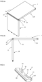
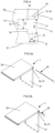
FIG. 1a shows a 3D view from above of a set in an unassembled/dismantled state of an aspect of the invention. -
FIG. 1b shows a side view of a set in an unassembled/dismantled state of an aspect of the invention. -
FIG. 1c shows a 3D view from below of a set in an unassembled/dismantled state of an aspect of the invention. -
FIG. 2a shows a 3D view from above of a set in an assembled state of an aspect of the invention. -
FIG. 2b shows a side view of a set in an assembled state of an aspect of the invention. -
FIG. 3 shows an embodiment of a flexible tongue according to an aspect of the invention. -
FIG. 4 shows a side view of an enlargement of a part of the first panel. -
FIGS. 5a-5b show a 3D view from above of a set and a dismantling-rod according to an aspect of the invention during dismantling of the set. -
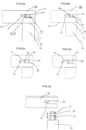
FIGS. 6a-6e show an enlargement of a part of the set and the dismantling-rod during dismantling of the set from an assembled state to a dismantled state. -
FIGS. 7a - 7b show view from above and a side view of an embodiment of the second panel not according to the invention. -
FIGS. 8a - 8b show view from above and a side view of an embodiment of the first panel according to an aspect of the invention. -
FIG. 9 shows a cross sectional view of a part of the second panel inFIG. 7a, 7b not according to the invention. -
FIG. 10 shows a side view of a part of the first panel inFIG. 8a, 8b and a rod-shaped element according to an aspect of the invention. -
FIG. 11 shows a 3D view from above of a part of the first panel inFIG. 7a, 7b not according to the invention. -
FIGS. 12a - 12b show a side view and a 3D view from above of a rod-shaped element according to an aspect of the invention. -
FIGS. 13a - 13b show a side view and a 3D view from above of a rod-shaped element according to an aspect of the invention. -
FIGS. 14a - 14b show a side view and a 3D view from above of a rod-shaped element according to an aspect of the invention. -
FIG. 15 shows a side view of a set in an assembled state and in an unassembled stat of an aspect of the invention. -
FIG. 16 shows a side view of an enlargement of a part of the set inFIG. 15 . -
FIG. 17 shows a view from above of 2 of the second panels inFIG. 15 . -
FIG. 18a-18b shows a side view and a top view of an embodiment of the attachment groove. -
FIG. 18c shows a side view of a part of an embodiment of the second panel - Aspects of the present disclosure will be described more fully hereinafter with reference to the accompanying drawings. Like numbers in the drawings refer to like elements throughout.
- The terminology used herein is for the purpose of describing particular aspects of the disclosure only, and is not intended to limit the disclosure. As used herein, the singular forms "a", "an" and "the" are intended to include the plural forms as well, unless the context clearly indicates otherwise.
- In the drawings and specification, there have been disclosed exemplary aspects of the disclosure. However, many variations and modifications can be made to these aspects without substantially departing from the principles of the present disclosure. Thus, the disclosure should be regarded as illustrative rather than restrictive, and not as being limited to the particular aspects discussed above. Accordingly, although specific terms are employed, they are used in a generic and descriptive sense only and not for purposes of limitation, for example, definition of dimensions such as width or breadth or height or length or diameter depends on how exemplary aspects are depicted, hence, if depicted differently, a shown width or diameter in one depiction is a length or thickness in another depiction.
- It should be noted that the word "comprising" does not necessarily exclude the presence of other elements or steps than those listed and the words "a" or "an" preceding an element do not exclude the presence of a plurality of such elements. It should further be noted that any reference signs do not limit the scope of the claims and that several "means", "units" or "devices" may be represented by the same item of hardware.
- A first embodiment of the invention is shown in
FIGS 1a - 4 including aset 1 comprising afirst panel 10, asecond panel 20 and amechanical locking device 30 for locking thefirst panel 10 to thesecond panel 20. Thefirst panel 10 comprises afirst edge surface 11 and afirst panel surface 12. Thesecond panel 20 comprises asecond edge surface 21 and asecond panel surface 22. Thefirst edge surface 11 is facing thesecond panel surface 22 in a locked position of the first and thesecond panel mechanical locking device 30 comprises a rod-shapedelement 31 at thefirst edge surface 11 and aninsertion groove 32 at thesecond panel surface 22. Themechanical locking device 30 further comprises anedge groove 33 at thesecond edge surface 21 and aflexible tongue 6 positioned in theedge groove 33. The rod-shapedelement 31 comprises arecess 34. The rod-shapedelement 31 is configured to be inserted into theinsertion groove 32. Theflexible tongue 6 is configured to cooperate with therecess 34 for a locking of thefirst panel 10 to thesecond panel 20 in a first direction which is perpendicular to thesecond panel surface 22. - The
first panel 10 and thesecond panel 20 are preferably panels for a furniture product and may be a part of a frame of a furniture product. - The
set 1 is preferably configured for locking thefirst panel 10 to thesecond panel 20 with thefirst panel surface 12 perpendicular or essentially perpendicular to thesecond panel surface 22. -
Fig. 1a-c disclose the set according to an aspect in an unassembled or dismantled state.Fig. 2a-b disclose the set according to an aspect in an assembled state. Theset 1 may be assembled by displacing thefirst panel 10 relative thesecond panel 20 in a direction which is perpendicular to thesecond panel surface 22. Themechanical locking device 20 may be configured to automatically lock thefirst panel 10 to thesecond panel 20 when the rod-shapedelement 31 is inserted into theinsertion groove 32 and thefirst edge surface 11 is arranged against thesecond panel surface 22. - The
insertion groove 32 is formed in thesecond panel surface 22 and in a core of thesecond panel 20. - The
second panel surface 22 may comprise a decorative layer and the insertion groove may extend though the decorative layer. - The insertion groove may be formed by mechanical cutting, such as drilling.
- An aspect of the
flexible tongue 6 is shown inFig. 3 . A first part of theflexible tongue 6 is configured to cooperate with theedge groove 33 and a second part is configured to cooperate with therecess 34 of the rod-shapedelement 31. - The second part may comprise a first bevel 65, which is configured to cooperate with the rod-shaped
element 31 during assembling, and a second bevel 64, which is configured to cooperate with therecess 34 for the locking. - The
flexible tongue 6 may comprise a flexible material to enable compression and a displacement of theflexible tongue 6 in theedge groove 33 during assembling and dismantling. - The
flexible tongue 6 may comprise an element which is flexible to enable compression and a displacement of theflexible tongue 6 in theedge groove 33 during assembling and dismantling and another element which is less flexible in order to improve the locking strength. - A part of a curved surface of an embodiment of the
flexible tongue 6 may be configured to be displaced against a surface, such as a cylindrical surface, of theedge groove 33. - The
flexible tongue 6 may comprise a first essentially straight edge and a second edge which comprises abendable part 61, preferably a first bendable part and a second bendable part. The first edge is preferably configured to cooperate with therecess 34 of the rod-shapedelement 31. The flexible tongue preferably comprises arecess 63 at each of said bendable parts. An advantage with this embodiment of the flexible tongue is that a stronger spring force may be obtained which may provide a stronger locking. - A locking surface of the
flexible tongue 6 may cooperate with a lockingsurface 62 of therecess 34 for the locking of thefirst panel 10 to thesecond panel 20. - The
first edge surface 11 may comprise two or more of said rod shapedelement 33 and thesecond panel surface 22 may comprise two or more of saidinsertion groove 32, preferably arranged linearly, wherein each of the rod-shapedelements 31 is configured to be inserted into one of theinsertion grooves 32. - An aspect of the rod-shaped
element 31 is shown inFIG. 6a-e which comprises an embodiment of therecess 34. The rod-shapedelement 31 has a longitudinal shape with a length direction L, which is parallel to the first panel surface. A first crosscut of the rod-shapedelement 31, in a plane parallel to thesecond panel surface 21 may have a circular shape, a rectangular shape, a star shape, an oval shape or a hexagon shape. The crosscut may be between therecess 34 and theedge 11. - A locking of the
first panel 10 to thesecond panel 20 in a second direction which is perpendicular to thefirst panel surface 22 may be obtained by cooperating locking surfaces between theinsertion groove 32 and the rod-shapedelement 31. - A locking of the first panel to the second panel in a third direction which is perpendicular to the first direction and the second direction surface may be obtained by cooperating locking surfaces between the
insertion groove 32 and the rod-shapedelement 31. - A second cross cut of the
insertion groove 32, in a plane parallel to the second panel surface, preferably has a shape that matches a first cross cut of the rod-shapedelement 31, in a plane parallel to the second panel surface. An advantage of this may be that an improved locking of thefirst panel 10 to thesecond panel 20 in a second direction is obtained and/or an improved locking of thefirst panel 10 to thesecond panel 20 in a third direction is obtained. - The
edge groove 33 and theinsertion groove 32 are disclosed in more detail inFIG. 4 , which is a cross cut along theinsertion groove 32. - The
edge groove 33 extends from thesecond edge surface 21 of thesecond panel 20 inwards in thesecond panel 20. Theedge groove 33 comprises aninner part 36 and anouter part 37. Theinner part 36 of the edge groove has a first height H1. Theouter part 37 of the edge groove has a second height H2. The height of the inner and outer part is seen in a direction that is parallel with thesecond end surface 21. Put in another way the height of the inner and outer part H1, H2 extend in the thickness of the second panel. The second height H2 of theouter part 37 is larger than the first height H1 of theinner part 36. Theouter part 37 is located closer to the second edge surface than the inner part. - The
inner part 36 of theedge groove 33 may comprise a first surface, an opposite second surface and abottom surface 35 extending between the first surface and the opposite second surface. According to the invention, theedge groove 33 is a bottom-ended groove comprising thebottom surface 35. - The
bottom surface 35 is positioned at a distance from theinsertion groove 32. - The
outer part 37 of theedge groove 33 may comprise a first surface, an opposite second surface and abottom surface 38 extending between the first surface and the opposite second surface. Thebottom surface 38 of thesecond part 37 comprises anopening 39 of thefirst part 36. - According to an aspect the height H1 of the
inner part 36 of theedge groove 33 is equal to or larger than a thickness of theflexible tongue 6. - According to an aspect the rod shaped
element 31 is connected to thefirst edge surface 11 at afirst end 41 and comprise arod surface 42 positioned between therecess 34 and asecond end 43 of the rod-shapedelement 31. - According to an aspect the difference between the second height H2 of the
outer part 37 of theedge groove 33 and the first height H1 of theinner part 36 of theedge groove 33 is equal to or larger than a length of therod surface 41 between therecess 34 and thesecond end 43 of the rod-shapedelement 31. - According to an aspect the difference between the second height H2 of the
outer part 37 of theedge groove 33 and the first height H1 of theinner part 36 of theedge groove 33 is or equal to or larger than a distance from anouter tip 66 of theflexible tongue 6 and asurface 67 of theflexible tongue 6 which cooperate with a surface of theinner part 36 of theedge groove 33. According to an aspect the difference between the second height H2 of theouter part 37 of theedge groove 33 and the first height H1 of theinner part 36 of theedge groove 33 is or equal to or larger than a distance from an outer tip of the flexible tongue and the lockingsurface 62 of theflexible tongue 6. - According to an aspect the second height H2 of the
outer part 37 of theedge groove 33 is 1.1 - 2.5 times larger than the first height H1 of theinner part 36. According to an aspect the second height H2 of theouter part 37 of theedge groove 33 is 1.1-1.5 times larger than the first height of the inner part. According to an aspect theflexible tongue 6 is arranged at thebottom surface 35 of theedge groove 33. - According to the invention, the
flexible tongue 6 is configured to be flexed inwards towards thebottom surface 35 to be completely positioned in theinner part 36 of theedge groove 33, as disclosed inFIG. 6b,c,d . - According to an aspect the
flexible tongue 6, in an unflexed state, is configured to be position partly in theouter part 37 and partly in theinner part 37 of the edge groove, as disclosed inFIG. 6a and e. - According to an aspect the
edge groove 33 is alongitudinal groove 33 that extends in a longitudinal direction of thesecond edge surface 22, as disclosed inFIG. 1a ,c and 2 a. - According to an aspect
second panel 20 comprise athird edge surface 23. According to an aspect theedge groove 33 of themechanical locking device 30 further is positioned at thethird edge surface 23 as disclosed inFIG. 2a . - According to an aspect the
second panel 20 comprises afourth edge surface 24. According to an aspect theedge groove 33 of themechanical locking device 30 further is positioned at thefourth edge surface 24, as disclosed inFIG. 2a . According to an aspect theedge groove 33 extends from thethird edge surface 23 to thefourth edge surface 24. - The
bendable part 61 of theflexible tongue 6 may be arranged at thebottom surface 35 of theedge groove 33. - The
flexible tongue 6 may be arranged at thebottom surface 35 of theedge groove 33. - The flexible tongue may be arranged between the
recess 34 and thebottom surface 35 of the edge groove in the locked position. - A part of the
flexible tongue 6 may be configured to be displaced against a surface of theedge groove 35, such as the first surface and/or the second surface. - According to an aspect and as disclosed in
FIG. 12a , b; 13a, b; 14a, b, the rod-shapedelement 31 have a longitudinal shape with the length direction L which is parallel to thefirst panel surface 12. The rod-shapedelement 31 comprises afirst part 51 at thefirst end 41 and asecond part 52 at thesecond end 43. Therecess 34 is according to an aspect comprised in thesecond part 52. - The
first part 51 of the rod-shapedelement 31 is configured to be inserted into anattachment groove 101 in thefirst edge surface 11, as disclosed inFIG. 1a ,6e ,8a, b ,10 ,18a and 18b. FIG 18a shows a side view andFIG 18b shows a top view of a part of an embodiment of thefirst panel 10. Thesecond part 52 of the rod-shapedelement 31 is according to an aspect configured to be inserted into theinsertion groove 32. According to an aspect the rod shapedelement 31 comprises athird part 53. The third part is located between the first andsecond part third part 53 has according to an aspect an extension perpendicular to the length direction L that is larger than the extension of theattachment groove 101 in thefirst edge surface 11 in the corresponding direction. By having a larger extension the third part is configured to restrict/define/limit the depth that thefirst part 51 could be inserted into the attachment groove. By limiting the length the rod-shapedelement 31 could be inserted into theattachment groove 101 in thefirst panel 10, the depth of theattachment groove 101 does not define the position of the rod-shapedelement 31 as long as the depth is larger than thefirst part 51. This opens up for that theattachment groove 101 could be manufactured with large tolerances without affecting the position of the rod-shaped element in theinsertion groove 32. This will lower the production costs of the set. - According to an aspect, as disclosed in
FIG. 13a , b; 14a, b, thethird part 53 is integrated in thesecond part 52. According to an aspect the extension perpendicular to the length direction L of thethird part 53 is equal to the extension of thesecond part 52 in the corresponding direction. - According to an aspect, as disclosed in
FIG. 12a, b , the extension perpendicular to the length direction L of thethird part 53 is larger than the extension D1 of theinsertion groove 32 in the corresponding direction, such that thethird part 53 is configured to restrict/define/limit the depth that thesecond part 52 could be inserted into theinsertion groove 32. By this the length of the rod-shapedelement 31 that could be inserted into theinsertion groove 32 is limited and defined and lower the tolerances on theset 1 for positioning the rod-shapedelement 31 in an intended locking position in view of theflexible tongue 6. - According to an aspect the
third part 53 comprise aflange 54 extending perpendicular to the length direction L. - According to an aspect the
flange 54 is acircumferential flange 54. According to an aspect theflange 54 is rectangular, square, triangular, or star shaped. - According to an aspect the
first edge surface 11 comprise acounterbore 102 corresponding to a shape of thethird part 53. - According to an aspect the
second panel surface 22 of thesecond panel 20 may comprise acounterbore 102 corresponding to a shape of thethird part 53.FIG. 18c . shows a sideview of a part of thesecond panel 20. - According to an aspect a depth of the
counterbore 102 of thefirst edge surface 11 and/or thesecond panel surface 22 is equal to a thickness of thethird part 53 in the length direction L. - According to an aspect the first, second and
third part element 31 is made in one piece. - According to an aspect the
attachment groove 101 is a bottom-ended groove, such as a bottom ended drill hole, comprising a bottom surface which is positioned at a distance from thefirst edge surface 11 that is larger than a length of thefirst part 51 in the length direction L. - According to an aspect the
first part 51 of the rod-shapedelement 31 is configured to be attached to theattachment groove 101 by friction. - According to an aspect the rod-shaped
element 31 is made from one or more of a wood based material, a polymer material, preferably with a reinforcement, such as glass fibre or a metal. - According to an aspect one or more of the first, second and
third part element 31 has a substantial circular shape. - According to an aspect the rod-shaped
element 31 may be configured to be glued in theattachment groove 101 in thefirst edge surface 11. - According to an aspect the
first part 51 of the rod-shapedelement 31 comprise threads. According to an aspect thefirst part 51 of the rod-shapedelement 31 comprisebarbs 54, as disclosed inFIG. 14 a, b . According to an aspect the rod-shapedelement 31 is configured to be locked in theattachment groove 101 by a friction connection or by a mechanically connection, such as the threads or by a locking element, such as thebarbs 54. - The
insertion groove 32 is according to an aspect a bottom-ended groove, such as a bottom ended drill hole, comprising abottom surface 46, which is positioned at a distance from theedge groove 33. - The
insertion groove 32 may have afirst part 43 on a first side of theedge groove 33 and a second part 44 on a second side of theedge groove 33, wherein the second part comprises thebottom surface 46 and side walls, wherein, in a locked position, the rod-shapedelement 31 passes through thefirst part 43 of theinsertion groove 32, through theedge groove 33 and into the second part 44 of theinsertion groove 32. -
FIG. 6a shows a cross cut of thefirst panel 10 and thesecond panel 20 in a locked position, i.e. in an assembled position. The insertion groove, according to an aspect, extends from thesecond panel surface 22 to theedge groove 33. - The rod-shaped
element 21 may be configured to cooperate, for the locking in the second direction, with the side walls the second part 44 of theinsertion groove 32. - The rod-shaped
element 31 may be configured to cooperate, in a locked position, with thebottom surface 46. - The
first part 43 of theinsertion groove 32 may comprise side walls, wherein the rod-shapedelement 31 may be configured to cooperate, for the locking in the second direction, with side walls of thefirst part 43. - The sidewalls may comprise material of the core of the
second panel 20. - The
second edge surface 21 may be essentially perpendicular to thesecond panel surface 22. - According to an aspect the
first panel 10 may be assembled by displacing thefirst panel 10 relative thesecond panel 20 in a direction which is perpendicular to thesecond panel surface 22. Themechanical locking device 30 is according to an aspect configured to automatically lock thefirst panel 10 to thesecond panel 20 when the rod-shapedelement 31 is inserted into theinsertion groove 32 and thefirst edge surface 11 is arranged against thesecond panel surface 22. - According to an aspect the assembled first and
second panel second panel - Hereafter the method of dismantling the
first panel 10 from thesecond panel 20 will be described with reference toFIG.5a, b and6a-e . - In the assembled position the
outer part 37 of theedge groove 33 is configured to receive a dismantling-rod 40. The dismantling-rod 40 is a rod shaped element that is insertable in theouter part 37 of theouter groove 33. The dismantling-rod has a longitudinal shape with a first end and a second end. The second end of the dismantling-rod 40 is adapted to be gripped by a user and the first end is adapted to be inserted into theedge groove 33. The cross sectional shape of the dismantling-rod 40 in a direction perpendicular to its longitudinal length is according to an aspect a polygon, for instance a trapezoid as disclosed inFIG. 6b and 6c . According to an aspect the cross sectional shape of the dismantling-rod 40 in a direction perpendicular to its longitudinal length is round, square, rectangular or triangular. - According to an aspect the dismantling-
rod 40 is flexible such that it is insertable into theedge groove 33 from thesecond edge surface 21. As the dismantlingrod 40 is inserted from the second edge surface it flexes and bends such that it is positioned at theflexible tongue 6 and therecess 34. According to an aspect the dismantling-rod 40 is insertable into theedge groove 33 from thethird edge surface 23. According to an aspect the dismantling-rod 40 is insertable into theedge groove 33 from thefourth edge surface 24. - When a user should dismantle the
first panel 10 from thesecond panel 20 and thus unlock themechanical locking device 30, the user inserts the first end of the dismantling-rod 40 into theouter part 37 of theedge groove 33. When the dismantlingrod 40 is inserted and received in theedge groove 33, the rod-shapedelement 33 is configured to cooperate with the dismantling-rod 40 for flexing theflexible tongue 6 inwards in theedge groove 33. When the dismantling-rod 40 is inserted into theouter part 37, it makes contact with therecess 34 of the rod-shapedelement 31 and theflexible tongue 6. The shape of the dismantling-rod 40 corresponds to the shape of therecess 34 and when the dismantling-rod 40 is inserted further into theouter part 37 it will be positioned in therecess 34 and flex theflexible tongue 6 out of therecess 34 towards theinner part 36 of theedge groove 33, as disclosed inFIG. 6b . - When the
flexible tongue 6 is flexed inwards in theedge groove 33, the rod-shapedelement 33 is configured to be moveable in theinsertion groove 32, as disclosed inFIG. 6b . According to an aspect and the orientation of the set, the rod-shaped element is moveable upwards or downwards, i.e. it is moveable outwards in the direction of thefirst edge surface 11. As the rod-shapedelement 31 is moved the dismantling-rod 40 will after being moved a distance make contact with the inner wall of theouter part 37 of theedge groove 33, as disclosed inFIG. 6c . According to an aspect the distance that the rod-shaped element could be moved is the difference between the first height H1 of theinner part 36 and the second height H2 of theouter part 37. In this position theflexible tongue 6 is positioned at therod surface 42 of the rod-shapedelement 31. Therod surface 42 restricts that theflexible tongue 6 is flexed outwards. According to an aspect theflexible tongue 6 flexes outward until it makes contact with therod surface 42 of the rod-shapedelement 31. - When the rod-shaped
element 31 is moved upwards in theinsertion groove 32 by the user and theflexible tongue 6 is not positioned in therecess 34, the dismantling-rod 40 is configured to be moved out of theedge groove 33. As theflexible tongue 6 is restricted from being flexed back into therecess 34 by therod surface 42 in this position, the dismantling-rod 40 could be extracted from theouter part 37 without themechanical locking device 30 returning to its locked position. - After the dismantling-
rod 40 has been moved out of theedge groove 33 the rod-shapedelement 31 is configured to be moved further outwards and out of theinsertion groove 32 to dismantle thefirst panel 10 from thesecond panel 20. Thefirst panel 10 is now dismantled from thesecond panel 20. - According to an aspect when the rod-shaped
element 31 is moved outwards in theinsertion groove 32, theflexible tongue 6 is flexed outwards towards therod surface 42 of the rod-shapedelement 31. - According to an aspect a method for dismantling the
set 1 from a locked position to a dismantled position by inserting the dismantling-rod 40 into theouter part 37 of theedge groove 33 and move theflexible tongue 6 out of therecess 34 of the rod-shapedelement 33 by flexing theflexible tongue 6 inwards in theedge groove 33, move the rod-shapedelement 31 and the dismantling-rod 40 outwards in theinsertion groove 32, retract the dismantling-rod 40 out of theedge groove 33, and retract the rod-shapedelement 31 further outwards and out of theinsertion groove 32 to dismantle thefirst panel 10 from thesecond panel 20. - According to an aspect the step of moving comprise moving the rod-shaped
element 31 such a distance outwards that theflexible tongue 6 is unable to flex back into therecess 34. - After the
first panel 10 has been dismantled from thesecond panel 20 thefirst panel 10 can be assembled once again to thesecond panel 20 or to another panel comprising corresponding features. After thefirst panel 10 has been dismantled from thesecond panel 20 thesecond panel 20 can be assembled once again to thesecond panel 10 or to another panel comprising corresponding features. - According to an aspect not according to the invention, as disclosed in
FIG. 9, 10, 11 theset 1 comprise asecond panel 20a and themechanical locking device 30 comprises apanel groove 133 at asecond panel surface 22 of thesecond panel 20a. Thepanel groove 133 has the same function as theedge groove 33 disclosed above, however, according to this aspect the groove is positioned at thesecond panel surface 22 instead of at thesecond edge surface 21. Thepanel groove 133 extends at an angle α in thesecond panel 20a in view of thesecond panel surface 22. Put in another way, thepanel groove 133 is made in thesecond panel 20a and is angled with an angle α in view of the second panel surface, as is disclosed inFIG. 9 . - The
flexible tongue 6, not disclosed inFIG. 9 , is according to an aspect positioned in thepanel groove 133. The rod-shapedelement 31 is positioned at thefirst edge surface 11 as disclosed above. Theinsertion groove 32 is, according to this aspect, positioned at thesecond panel surface 22 and extends from thesecond panel surface 22 to thepanel groove 133. - According to an aspect the rod-shaped
element 31 is configured to be inserted into theinsertion groove 32 and the rod-shapedelement 31 comprises arecess 34. - According to an aspect the
flexible tongue 6 is configured to cooperate with therecess 34 for a locking of thefirst panel 10 to thesecond panel 20a in a first direction which is perpendicular to thesecond panel surface 22. - According to an aspect the angle α is between 10°-80° degrees. According to an aspect the angle α is between 10°-70° degrees. According to an aspect the angle is between 20-70 degrees. According to an aspect the angle α is between 15°-50° degrees. According to an aspect the angle α is between 25°-35° degrees. According to an aspect the
second edge surface 21 of thesecond panel 20a is positioned at a distance from thepanel groove 133. - According to an aspect a width W1 of the
panel groove 133 in thesecond panel surface 22 is smaller than a width W2 of thefirst edge surface 11. Put in another way thefirst edge surface 11 of thefirst panel 10 covers thepanel groove 133 when thefirst panel 10 is locked towards thesecond panel 20a. - According to an aspect the width W1 of the
panel groove 133 in thesecond panel surface 22 is larger than a diameter D2, disclosed inFIG. 10 , of the rod-shapedelement 133. - According to an aspect the
panel groove 133 is a bottom-ended groove, comprising abottom surface 135 which is positioned at a distance from theinsertion groove 32. - According to an aspect the
flexible tongue 6 is arranged at thebottom surface 135 of thepanel groove 133. - According to an aspect the
flexible tongue 6 is configured to be flexed inwards towards thebottom surface 135 to be completely positioned in thepanel groove 133. - According to an aspect the
flexible tongue 6, in an unflexed state, is configured to be position partly in thepanel groove 133 and partly in theinsertion groove 32. - According to an aspect the
panel groove 133 is alongitudinal groove 133 that extends in a longitudinal direction of the secondplanar surface 22. - According to an aspect the longitudinal direction of the
longitudinal groove 133 is substantially parallel to thesecond edge surface 21. - According to an aspect the
second panel 20a comprise athird edge surface 23 and that thepanel groove 133 of themechanical locking device 30 further is positioned at thethird edge surface 23. - According to an aspect the
second panel 20a comprise afourth edge surface 24 and that thepanel groove 133 of themechanical locking device 30 further is positioned at thefourth edge surface 24. - According to an aspect the
panel groove 133 extends from thethird edge surface 23 to thefourth edge surface 24. - According to an aspect the
insertion groove 32 is a bottom-ended groove, such as a bottom ended drill hole, comprising abottom surface 46 which is positioned at a distance from thepanel groove 133. - According to an aspect the
first edge surface 11 comprises two or more of said rod-shapedelement 31 and thesecond panel surface 22 comprises two or more of saidinsertion groove 32 and one ormore panel groove 133, preferably arranged linearly, wherein each of the rod-shapedelements 31 is configured to be inserted into one of theinsertion grooves 32. - According to an aspect, in the locked position between the
first panel 10 and thesecond panel 20a, thepanel groove 133 is configured to receive the dismantling-rod 40. - When the dismantling
rod 40 is received in thepanel groove 133, the rod-shapedelement 31 is configured to cooperate with the dismantling-rod 40 for flexing theflexible tongue 6 inwards in thepanel groove 133. Thereafter, when theflexible tongue 6 is flexed inwards in thepanel groove 133, the rod-shapedelement 31 and the dismantling-rod 40 is configured to be moveable outwards in theinsertion groove 32 and out of theinsertion groove 32 to dismantle thefirst panel 10 from thesecond panel 20a. As thepanel groove 133 extend from thesecond panel surface 22 the dismantling could be made in less steps than the dismantling method described above. This is due to that theinsertion groove 32 and thepanel groove 133 is positioned at one and the same surface, thesecond panel surface 22. - According to an aspect the
mechanical locking device 30 is configured to automatically lock thefirst panel 10 to thesecond panel 20a when the rod-shapedelement 31 is inserted into theinsertion groove 32 and thefirst edge surface 11 is arranged against thesecond panel surface 22. - According to an aspect the
flexible tongue 6 is arranged between therecess 34 of the rod-shapedelement 31 and thebottom surface 135 of thepanel groove 133 in the locked position. According to an aspect thesecond edge surface 21 is essentially perpendicular to thesecond panel surface 22. - According to an aspect the rod-shaped
element 31 according to the above could be connected to asecond panel 20 comprising anedge groove 33 according to the above or to apanel groove 133 according to the above. - According to an aspect the
second panel more edge grooves 33 and one ormore panel grooves 133. According to an aspect thesecond panel first panels 10. Theinsertion groove 32 may be formed in thesecond panel surface 22 and in a core of thesecond panel 20. - The
second panel surface 22 may comprise a decorative layer and the insertion groove may extend though the decorative layer. - The insertion groove may be formed by mechanical cutting, such as milling or sawing.
- An edge element, such as an edge band, is according to an aspect attached to the second edge for covering the edge groove and for enforcing the
second edge 21. Embodiments of edge bands are shown inWO 2018/080387 . The edge element may be glued to the second edge or attached by a mechanical locking device, which may comprise a part that protrudes from the edge element and is configured to be inserted into theedge groove 33. The part may be attached to the edge groove by friction. The edge element is according to an aspect not covering the third and/or thefourth edge surface rod 40 could be inserted into theedge groove 33. The edge element is according to an aspect removable such that the dismantling-rod 40 could be inserted into theedge groove 33. - According to an aspect the second panel may comprise two or more of said
edge groove 33. - According to an aspect the
first panel 10 comprises two or more first edge surfaces 11 according to the above. Put in another way, one or more rod-shapedelements 31 can be positioned at two or more of the edges of thefirst panel 10, as disclosed inFIG. 15 and 17 . - According to an aspect one or more rod-shaped
elements 31 at onefirst edge surface 11 of onefirst panel 10 is positioned off-set in view of one or more rod-shaped elements at anotherfirst edge surface 11 of thefirst panel 10. By positioning the rod-shapedelements 31 off-set at different first edge surfaces 11 of thefirst panel 10, unintended assembly of different first andsecond panels elements 31 atfirst edge surface 11 only correspond to the position of theinsertion grooves 32 at thesecond panel surface 22 to which it intended to be connected. - According to an aspect one second panel could be connected to four first panels as disclosed in
FIG. 15 . According to an aspect thesecond panel 20 comprises two second panel surfaces 22 and that one ormore insertion grooves 32 extend from one of thesecond panel surface 22 and one ormore insertion grooves 32 extend from the othersecond panel surface 22 to acommon edge groove 33, as disclosed inFIG. 15 and 16 . - According to an aspect a panel could be a combination of the
first panel 10 and thesecond panel elements 31 at one edge and apanel groove 133 at a panel surface and/or an edge groove at another edge surface, as disclosed inFIG. 17 . - The
flexible tongue 6 may be according to the flexible tongue described and shown inFIGS 2A -2F and the related disclosure frompage 6, line 15 to page 7, line 2, inWO2015/105449 . - The core of the
first panel 10 and/or of thesecond panel first panel 10 and/or thesecond panel first panel 10 and/or thesecond panel - According to an aspect the
set 1 are one of a bottom piece of a drawer, a frame and a back piece of a furniture product. - According to an aspect the set of panels are resilient panels. The resilient panels may comprise a core comprising thermoplastic material. The thermoplastic material may be foamed.
- The thermoplastic material may comprise polyvinyl chloride (PVC), polyester, polypropylene (PP), polyethylene (PE), polystyrene (PS), polyurethane (PU), polyethylene terephthalate (PET), polyacrylate, methacrylate, polycarbonate, polyvinyl butyral, polybutylene terephthalate, or a combination thereof. The core may be formed of several layers.
- The aspects described above may comprise a decorative layer, such as a decorative foil comprising a thermoplastic material. The thermoplastic material of the decorative layer may be or comprise polyvinyl chloride (PVC), polyester, polypropylene (PP), polyethylene (PE), polystyrene (PS), polyurethane (PU), polyethylene terephthalate (PET), polyacrylate, methacrylate, polycarbonate, polyvinyl butyral, polybutylene terephthalate, or a combination thereof. The decorative foil is preferably printed, for example by direct printing, rotogravure, or digital printing. According to an aspect the decorative layer comprises melamine, a high pressure laminate (HPL) or a veneer.
- The aspects described above may comprise a wear layer such as a film or foil. The wear layer may comprise thermoplastic material. The thermoplastic material may be polyvinyl chloride (PVC), polyester, polypropylene (PP), polyethylene (PE), polystyrene (PS), polyurethane (PU), polyethylene terephthalate (PET), polyacrylate, methacrylate, polycarbonate, polyvinyl butyral, polybutylene terephthalate, or a combination thereof.
- The aspects described above may comprise a wood base core, such as HDF, MDF, plywood, particleboard, OSB or Masonite.
Claims (13)
- A set (1) comprising a first panel (10), a second panel (20) and a mechanical locking device (30) for locking the first panel (10) to the second panel (20), wherein- the first panel (10) comprises a first edge surface (11) and a first panel surface (12),- the second panel (20) comprises a second edge surface (21) and a second panel surface (22),- the first edge surface (11) is facing the second panel surface (22) in a locked position of the first and the second panel (10, 20),- the mechanical locking device (30) comprises an edge groove (33) at the second edge surface (21), a flexible tongue (6) positioned in the edge groove (33), a rod-shaped element (31) at the first edge surface (11) and an insertion groove (32) at the second panel surface (22) extending from the second panel surface (22) to the edge groove (33),- the rod-shaped element (31) is configured to be inserted into the insertion groove (32) and the rod-shaped element (31) comprises a recess (34),- the flexible tongue (6) is configured to cooperate with the recess (34) for a locking of the first panel (10) to the second panel (20) in a first direction which is perpendicular to the second panel surface (22),- an inner part (36) of the edge groove (33) has a first height (H1) and an outer part (37) of the edge groove (37) has a second height (H2) that is larger than the first height (H1),- the edge groove (33) is a bottom-ended groove, comprising a bottom surface (35) which is positioned at a distance from the insertion groove (32), andthe flexible tongue (6) is configured to be flexed inwards towards the bottom surface (35) to be completely positioned in the inner part (36) of the edge groove (33).
- The set (1) as claimed in claim 1, wherein the rod shaped element (31) is connected to the first edge surface (11) at a first end (41) and comprises a rod surface (42) positioned between the recess (34) and a second end (43) of the rod-shaped element (31).
- The set (1) as claimed in claim 1 or 2, wherein the height (H1) of the inner part (36) of the edge groove (33) is equal to or larger than a thickness of the flexible tongue (6)
- The set (1) as claimed in claim 2 or 3, wherein the difference between the second height (H2) of the outer part (37) of the edge groove (33) and the first height (H1) of the inner part (36) of the edge groove (33) is equal to or larger than a length of the rod surface (42) between the recess (34) and the second end (43) of the rod-shaped element (31) or equal to or larger than a distance from an outer tip 66 of the flexible tongue (6) and a surface (67) of the flexible tongue (6) which cooperate with a surface of the inner part (36) of the edge groove (33).
- The set (1) as claimed in any of the preceding claims, wherein the second height (H2) of the outer part (37) of the edge groove (33) is 1,1 - 2,5 times larger than the first height (H1) of the inner part (36), preferably 1,1-1,5 times larger than the first height (H1) of the inner part (36).
- The set (1) as claimed in any of the preceding claims , wherein the inner part (36) of the edge groove (33) is positioned closer to the bottom surface (35) than the outer part (37) of the edge groove (33).
- The set (1) as claimed in any of the preceding claims , wherein the flexible tongue (6) is arranged at the bottom surface (35) of the edge groove (33).
- The set (1) as claimed in any of the preceding claims, wherein the flexible tongue (6), in an unflexed state, is configured to be position partly in the outer part (37) and partly in the inner part (36) of the edge groove (33).
- The set (1) as claimed in any one of the preceding claims, wherein the edge groove (33) is a longitudinal groove (33) that extends in a longitudinal direction of the second edge surface (21).
- The set (1) as claimed in any of the preceding claims, wherein the second panel (20) comprise a third edge surface (23) and that the edge groove (33) of the mechanical locking device (30) further is positioned at the third edge surface (23).
- The set (1) as claimed in any of the preceding claims, wherein the second panel (20) comprise a fourth edge surface (24) and that the edge groove (33) of the mechanical locking device (30) further is positioned at the fourth edge surface (24).
- The set (1) as claimed in claim 11, wherein the edge groove (33) extends from a third edge surface (23) of the second panel (20) to the fourth edge surface (24).
- The set (1) as claimed in any one of the preceding claims, wherein the insertion groove (32) is a bottom-ended groove, such as a bottom ended drill hole, comprising a bottom surface (46) which is positioned at a distance from the edge groove (33) that is equal to or smaller than the difference between the second height (H2) of the outer part (37) of the edge groove (33) and the first height (H1) of the inner part (36) of the edge groove (33).
Applications Claiming Priority (2)
| Application Number | Priority Date | Filing Date | Title |
|---|---|---|---|
| SE1850445 | 2018-04-18 | ||
| PCT/SE2019/050361 WO2019203721A1 (en) | 2018-04-18 | 2019-04-17 | Set of panels with a mechanical locking device |
Publications (3)
| Publication Number | Publication Date |
|---|---|
| EP3781823A1 EP3781823A1 (en) | 2021-02-24 |
| EP3781823A4 EP3781823A4 (en) | 2022-01-19 |
| EP3781823B1 true EP3781823B1 (en) | 2024-04-10 |
Family
ID=68236277
Family Applications (1)
| Application Number | Title | Priority Date | Filing Date |
|---|---|---|---|
| EP19788887.8A Active EP3781823B1 (en) | 2018-04-18 | 2019-04-17 | Set of panels with a mechanical locking device |
Country Status (4)
| Country | Link |
|---|---|
| US (2) | US11448252B2 (en) |
| EP (1) | EP3781823B1 (en) |
| CN (1) | CN112119226B (en) |
| WO (1) | WO2019203721A1 (en) |
Families Citing this family (32)
| Publication number | Priority date | Publication date | Assignee | Title |
|---|---|---|---|---|
| UA109938C2 (en) | 2011-05-06 | 2015-10-26 | MECHANICAL LOCKING SYSTEM FOR CONSTRUCTION PANELS | |
| UA120422C2 (en) | 2013-09-16 | 2019-12-10 | Велінге Інновейшн Аб | An assembled product and a method of assembling the assembled product |
| US9726210B2 (en) | 2013-09-16 | 2017-08-08 | Valinge Innovation Ab | Assembled product and a method of assembling the product |
| EA031843B1 (en) | 2014-01-10 | 2019-02-28 | Велинге Инновейшн Аб | Furniture panel |
| US9714672B2 (en) | 2014-01-10 | 2017-07-25 | Valinge Innovation Ab | Panels comprising a mechanical locking device and an assembled product comprising the panels |
| US10876562B2 (en) | 2014-05-09 | 2020-12-29 | Valinge Innovation Ab | Mechanical locking system for building panels |
| UA120109C2 (en) | 2014-12-19 | 2019-10-10 | Велінґе Інновейшн Аб | Panels comprising a mechanical locking device and an assembled product comprising the panels |
| EP3285620A4 (en) | 2015-04-21 | 2018-11-14 | Välinge Innovation AB | Panel with a slider |
| JP6713486B2 (en) | 2015-04-30 | 2020-06-24 | ベーリンゲ、イノベイション、アクチボラグVaelinge Innovation Ab | Panel with fastening device |
| CN108026956B (en) | 2015-09-22 | 2020-07-17 | 瓦林格创新股份有限公司 | Panel comprising a mechanical locking device and assembled product comprising said panel |
| AU2016364705B2 (en) | 2015-12-03 | 2021-02-25 | Välinge Innovation AB | Panels comprising a mechanical locking device and an assembled product comprising the panels |
| BR112018014151B1 (en) | 2016-01-26 | 2022-12-27 | Vãlinge Innovation Ab | ASSEMBLY OF PANELS COMPRISING A MECHANICAL LOCKING DEVICE |
| EP3411599B1 (en) | 2016-02-04 | 2021-03-31 | Välinge Innovation AB | A set of panels for an assembled product |
| PT3416792T (en) | 2016-02-15 | 2021-01-28 | Vaelinge Innovation Ab | A method for forming a panel for a furniture product |
| EA037341B1 (en) | 2016-10-27 | 2021-03-15 | Велинге Инновейшн Аб | Set of panels with a mechanical locking device |
| MY196739A (en) | 2017-05-15 | 2023-05-03 | Valinge Innovation Ab | Elements and a locking device for an assembled product |
| WO2019125292A1 (en) | 2017-12-22 | 2019-06-27 | Välinge Innovation AB | A set of panels, a method for assembly of the same and a locking device for a furniture product. |
| WO2019125291A1 (en) | 2017-12-22 | 2019-06-27 | Välinge Innovation AB | A set of panels, a method for assembly of the same and a locking device for a furniture product |
| EA202092196A1 (en) | 2018-03-23 | 2021-01-14 | Велинге Инновейшн Аб | PANELS CONTAINING MECHANICAL LOCKING DEVICE AND ASSEMBLED PRODUCT CONTAINING PANELS |
| BR112020020666A2 (en) | 2018-04-18 | 2021-01-12 | Välinge Innovation AB | PANEL SET WITH MECHANICAL LOCKING DEVICE |
| KR20200141076A (en) | 2018-04-18 | 2020-12-17 | 뵈린게 이노베이션 에이비이 | Symmetrical tongue and tea-cross |
| WO2019203722A1 (en) | 2018-04-18 | 2019-10-24 | Välinge Innovation AB | Set of panels with a mechanical locking device |
| US11614114B2 (en) | 2018-04-19 | 2023-03-28 | Valinge Innovation Ab | Panels for an assembled product |
| JP2021535330A (en) | 2018-08-30 | 2021-12-16 | ベーリンゲ、イノベイション、アクチボラグVaelinge Innovation Ab | A set of panels with a mechanical locking device |
| EP3834661A1 (en) | 2019-12-11 | 2021-06-16 | Välinge Innovation AB | Mechanical locking system for panels |
| US11441590B2 (en) | 2019-12-19 | 2022-09-13 | Valinge Innovation Ab | Set of panels with a mechanical locking device |
| WO2021150162A1 (en) | 2020-01-22 | 2021-07-29 | Välinge Innovation AB | Set of panels with a mechanical locking device |
| US11702844B2 (en) | 2020-06-05 | 2023-07-18 | Valinge Innovation Ab | Building panels comprising a locking device |
| CN115867171A (en) * | 2020-07-17 | 2023-03-28 | 瓦林格创新股份有限公司 | Mechanical locking system for panels |
| EP4258943A1 (en) | 2020-12-11 | 2023-10-18 | Välinge Innovation AB | Rail for cabinets |
| CA3205979A1 (en) | 2021-01-07 | 2022-07-14 | Valinge Innovation Ab | Wedge-shaped tongue insertion groove |
| CN112922943B (en) * | 2021-02-27 | 2023-03-21 | 广东精诺五金实业有限公司 | Connecting device |
Family Cites Families (329)
| Publication number | Priority date | Publication date | Assignee | Title |
|---|---|---|---|---|
| US291032A (en) | 1884-01-01 | Isaac g- | ||
| DE228872C (en) | ||||
| US634581A (en) | 1898-11-21 | 1899-10-10 | Robert H Miller | Carpenter's square. |
| US701000A (en) | 1901-07-31 | 1902-05-27 | Carl F W Ahrens | File-cabinet. |
| US861911A (en) | 1905-11-04 | 1907-07-30 | William Stewart | Joint for articles of furniture or woodwork. |
| US881673A (en) | 1907-03-11 | 1908-03-10 | Arthur L Ellison | Wardrobe or safe. |
| US1534468A (en) | 1922-10-30 | 1925-04-21 | Jr John J Shea | Joint structure |
| US1533099A (en) | 1924-07-14 | 1925-04-14 | Robert E Carroll | Square-corner glue joint |
| GB245332A (en) | 1925-05-04 | 1926-01-07 | George Hugh Foster | An improved dowelled joint for woodwork and the like |
| US1800386A (en) | 1926-08-28 | 1931-04-14 | Andrew Hoffman Mfg Company | Display rail |
| US1800387A (en) | 1926-12-30 | 1931-04-14 | Andrew Hoffman Mfg Company | Article-supporting device |
| US1723306A (en) * | 1927-08-02 | 1929-08-06 | Harry E Sipe | Resilient attaching strip |
| US1802245A (en) | 1930-08-26 | 1931-04-21 | Clarence L Foretich | Display stand and shelving |
| US1954242A (en) | 1932-07-28 | 1934-04-10 | Thomas E Heppenstall | Dovetail spring joint |
| US2360451A (en) | 1942-06-02 | 1944-10-17 | Stone Abraham | Collapsible clothing container |
| US2362904A (en) | 1943-01-20 | 1944-11-14 | Allied Purchasing Corp | Joint for demountable furniture |
| US2496184A (en) | 1946-06-11 | 1950-01-31 | Canon Paul L Von | Furniture drawer construction and method |
| US2681483A (en) | 1948-10-14 | 1954-06-22 | Morawetz Hugo | Dowel connection |
| DE1107910B (en) | 1957-03-26 | 1961-05-31 | Curt Weinert | Flexible duebel |
| CH365507A (en) | 1958-11-17 | 1962-11-15 | Antonius Bus Johannes | Device for connecting perpendicular walls with automatic locking, in particular furniture walls |
| US3002630A (en) | 1960-05-24 | 1961-10-03 | Robert E Heisser | Toothbrush rack |
| US3195968A (en) | 1962-12-06 | 1965-07-20 | Lok Trim Corp | Knock-down furniture |
| DE1240638B (en) | 1963-03-07 | 1967-05-18 | Kueche | Dismountable furniture |
| GB1022377A (en) | 1963-08-19 | 1966-03-09 | Trepatent As | Arrangement of building sections for cupboards, benches or other equipment |
| US3313054A (en) | 1965-06-09 | 1967-04-11 | Poster Products Inc | Display devices |
| IS831B6 (en) | 1965-10-28 | 1973-04-12 | Nordischer Maschinenbau Rud. BaaderNordischer Maschinenbau, Rud. Baader | Method of removing the liver from the fishToys to decapitate the highly cut fish so that the wet bone remains on the fish |
| US3410441A (en) | 1966-06-29 | 1968-11-12 | Jeff S. Rhyne | Container |
| US3347610A (en) | 1966-07-28 | 1967-10-17 | Pilliod Cabinet Company | Cabinet construction |
| DE1955922C3 (en) | 1969-11-06 | 1974-01-10 | Hefendehl, Hansfriedrich, 5893 Kierspe | Box furniture made of plastic |
| US3722704A (en) | 1970-07-23 | 1973-03-27 | Castelli Sas Anonima | Structural components for the composition of disassemblable pieces offurniture |
| US3730568A (en) * | 1971-03-15 | 1973-05-01 | F Giovannetti | Connector |
| DE2153713A1 (en) * | 1971-10-28 | 1973-05-03 | Groth | PANEL CONSTRUCTION SYSTEM WITH CLAMPING-IN CONNECTING ELEMENTS |
| US3765465A (en) | 1972-01-05 | 1973-10-16 | Deutsch Fastener Corp | Retractable captive fastener |
| US3742807A (en) | 1972-02-03 | 1973-07-03 | D Manning | Leveling and locking pin |
| DE2206684C2 (en) * | 1972-02-12 | 1981-12-17 | Vario-Werke Dichmann Ag, 6233 Kelkheim | Connection fitting for furniture sections - has stud head and locking wedge with wedge surfaces interacting with locking member |
| GB1398187A (en) | 1972-06-22 | 1975-06-18 | Schreiber Furniture | Kitchen cabinets |
| US3884002A (en) | 1973-03-15 | 1975-05-20 | American Store Equip | Partition system |
| BE810507A (en) * | 1974-02-01 | 1974-05-29 | MEANS OF ASSEMBLING TWO WALLS OF CABINET OR FURNITURE. | |
| DE2414104A1 (en) | 1974-03-23 | 1975-10-09 | Alfer Alu Fertigbau | Fastener for wooden shelving - comprises straight locking pins engaged by pressure of support plate |
| DE2514357C3 (en) | 1974-04-02 | 1979-03-22 | Takeshi Tokio Shimizu | Fitting for the pivotable connection of a furniture panel with a fixed furniture part |
| US3885845A (en) | 1974-06-27 | 1975-05-27 | Hans Krieks | Knock-down furniture system |
| US3981118A (en) | 1974-10-17 | 1976-09-21 | The Goodyear Tire & Rubber Company | Clamping insert |
| US4012090A (en) * | 1975-11-05 | 1977-03-15 | Raymond Pfeifer | Knockdown put-together drawer |
| CA1062321A (en) | 1976-05-12 | 1979-09-11 | I. T. W. Ltd. | Grommets for furniture connectors |
| DE2635237A1 (en) | 1976-08-05 | 1978-02-09 | Heinze Fa R | FURNITURE HINGE |
| JPS53113160U (en) * | 1977-02-16 | 1978-09-08 | ||
| US4116510A (en) | 1977-03-03 | 1978-09-26 | Gte Automatic Electric Laboratories Incorporated | Chassis formed of sheet stock |
| US4099887A (en) | 1977-07-18 | 1978-07-11 | Einhard Mackenroth | Structural joints |
| US4222544A (en) | 1977-08-10 | 1980-09-16 | Kenneth Crowder | Picture rail apparatus |
| SE409603B (en) | 1977-12-20 | 1979-08-27 | Stockum Design Ab | CONNECTION |
| SE7809081L (en) | 1978-08-29 | 1980-03-01 | Hafa Fabriks Ab | DEVICE FOR COLLECTION OF CABINETS, MIRRORS, SHELVES AND OTHER DETAILS |
| US4211379A (en) | 1978-11-20 | 1980-07-08 | Morgan Myron B | Panelboard and mounting fixture combination |
| US4299067A (en) | 1979-10-30 | 1981-11-10 | J. C. Penney Company, Inc. | Partition connector system |
| US4308961A (en) | 1980-05-05 | 1982-01-05 | Kunce Thomas M | Article supporting structure |
| US4324517A (en) | 1980-06-16 | 1982-04-13 | Sps Technologies, Inc. | Panel fastener assembly with retainer ring |
| DE3047642A1 (en) | 1980-12-17 | 1982-10-28 | Arturo Salice S.p.A., 22060 Novedrate, Como | CONNECTING FITTING |
| DE3103281C2 (en) | 1981-01-31 | 1984-05-10 | C + A Dick GmbH, 5275 Bergneustadt | Material cupboard |
| FR2501805A1 (en) | 1981-03-10 | 1982-09-17 | Haeusler Roland | NEW TYPE TENON AND MORTISE GENDER ASSEMBLY SYSTEM AND FURNITURE ARTICLES INCORPORATING THE SAME SYSTEM |
| FR2517187A1 (en) | 1981-12-01 | 1983-06-03 | Beaux Dominique | DETACHABLE BOX FOR FURNITURE USE |
| US4509648A (en) | 1982-07-26 | 1985-04-09 | The Stanley Works | Merchandising display system and components therefor |
| US4593734A (en) | 1983-09-26 | 1986-06-10 | M. Bosley Wright | Frame routing apparatus |
| US4629076A (en) | 1984-05-10 | 1986-12-16 | Amstore Corporation | Slatboard |
| GB2163825B (en) | 1984-08-30 | 1988-03-02 | Hettich Paul Gmbh & Co | Furniture connector |
| US4595105A (en) | 1984-09-12 | 1986-06-17 | Gold Kenneth S | Interlocking bookrack |
| US4750794A (en) | 1984-11-21 | 1988-06-14 | Bass Cabinet Manufacturing, Inc. | Slide-fitted article of furniture |
| US4597122A (en) | 1985-06-10 | 1986-07-01 | Hirsh Company | Free-standing drawer |
| US4615448A (en) | 1985-09-27 | 1986-10-07 | Masonite Corporation | Display panel |
| US4891897A (en) | 1985-12-12 | 1990-01-09 | Gieske Detlef J | Display panel |
| FR2597173B1 (en) | 1986-04-10 | 1988-10-07 | Forschle Andre | DEVICE FOR EASILY ASSEMBLING AND MODIFYING THE COMPOSITION OF A KITCHEN FURNITURE |
| GB8612597D0 (en) | 1986-05-23 | 1986-07-02 | George W R | Joint between members |
| FR2602013B1 (en) | 1986-07-25 | 1988-12-30 | Kapikian Jean Claude | ASSEMBLY SYSTEM OF TENON AND MORTISE TYPE EASILY MOUNTABLE AND REMOVABLE |
| US4815908A (en) | 1986-10-14 | 1989-03-28 | Avibank Mfg., Inc. | Captive panel fastener assembly |
| US4844266A (en) | 1987-07-16 | 1989-07-04 | Intercraft Industries Corporation | Display system |
| CA1297934C (en) | 1987-07-24 | 1992-03-24 | Craig Mengel | Method of and structure for the joining of substantially rigidparts together |
| US4886326A (en) | 1988-01-29 | 1989-12-12 | Tetrad Marketing/Sales Ltd. | Interlock system for ready to assemble furniture, and furniture incorporating such system |
| US4961295A (en) | 1988-03-14 | 1990-10-09 | Kosch Sr Paul | Metal slat and wall system utilizing same |
| US4817900A (en) | 1988-05-09 | 1989-04-04 | Gorrie Advertising Management Limited | Support device for use on a display wall |
| JPH0266308A (en) | 1988-08-30 | 1990-03-06 | Kazuhiro Matsui | Assembly tool |
| IT215989Z2 (en) | 1988-09-02 | 1991-03-26 | Cattarozzi Andrea | MODULAR CONTAINER MODULAR AND MANUALLY TRANSPORTABLE, FOR THE STORAGE OF SUBSTANCES, IN SPECIAL WAY FOR FOOD USE |
| NL8802459A (en) | 1988-10-07 | 1990-05-01 | Homburg Interieuren B V | SHOW WALL. |
| US4944416A (en) | 1988-11-21 | 1990-07-31 | Petersen Robert J | Light-weight slot-wall display panel |
| US5471804A (en) | 1988-11-21 | 1995-12-05 | Winter, Iv; Amos G. | Building system using prefabricated building panels and fastening components used therewith |
| US4909581A (en) | 1988-12-12 | 1990-03-20 | American Moulding & Millwork Company | Drawer construction |
| WO1990007066A2 (en) | 1988-12-13 | 1990-06-28 | Rudolf Tanner | Connecting element for form-fitting connection |
| US5018323A (en) | 1989-05-12 | 1991-05-28 | Knud Clausen | Wall panel system |
| US5109993A (en) | 1989-10-31 | 1992-05-05 | Hutchison V James | Merchandise display system and merchandise holder therefor |
| US5138803A (en) | 1991-01-11 | 1992-08-18 | Commercial And Architectural Products, Inc. | Display panel assembly |
| US5121578A (en) | 1991-01-28 | 1992-06-16 | Holz Plastics, Inc. | Slat wall decorating system |
| CA2107465C (en) | 1991-04-01 | 1999-06-29 | Walter Lindal | Wooden frame building construction |
| US5209556A (en) | 1991-04-01 | 1993-05-11 | Anderson Robert F | Drawer assembly |
| US5114265A (en) | 1991-04-15 | 1992-05-19 | Grisley Kenneth M | Interlocking routed joint |
| US5299509A (en) | 1991-07-29 | 1994-04-05 | Ballard Donald M | Connectors for shelves and bins |
| US5125518A (en) | 1991-08-12 | 1992-06-30 | Innovative Accessories | Interlocking hanging system |
| CH684284A5 (en) | 1991-09-03 | 1994-08-15 | Edgar Probst | Rear wall fitting. |
| US5212925A (en) | 1991-11-21 | 1993-05-25 | Mcclinton John | Wall corner composite, mold and method for producing glazed unit for such |
| US5360121A (en) | 1992-08-07 | 1994-11-01 | Commerical And Architectural Products, Inc. | Slotted display wall panel |
| JP2530326Y2 (en) | 1992-08-24 | 1997-03-26 | 株式会社イトーキクレビオ | Device for connecting members in furniture etc. |
| CH685276A5 (en) | 1992-11-25 | 1995-05-31 | Werner Schmidt | Building elements for assembling shelves, cupboards and walling |
| ZA94676B (en) | 1993-02-03 | 1994-08-03 | Rohm & Haas | Reduction of microfoam in spray-applied waterborne composition. |
| US5423155A (en) | 1993-06-02 | 1995-06-13 | Darko Company, Inc. | Panel for resurfacing slat walls |
| US5403109A (en) * | 1993-06-09 | 1995-04-04 | Hon Industries Inc. | Fastening device for furniture construction and method of manufacture |
| US5499667A (en) | 1994-06-21 | 1996-03-19 | Nakanishi Construction Company | Drill/cutting bit, and method of making structural joint |
| US5527103A (en) | 1993-10-01 | 1996-06-18 | Pittman; Charles | Cabinet of improved design and construction |
| US5375802A (en) | 1993-11-17 | 1994-12-27 | Bill Branham Designs, Ltd. | Structure for fastening facing structural units |
| US5451102A (en) | 1994-01-13 | 1995-09-19 | Chuan; Yuan-Jung | Cabinet with connecting mechanism for two adjacent wall plate |
| US5499886A (en) | 1994-03-02 | 1996-03-19 | Sauder Woodworking Co. | Coupling assembly for furniture components |
| DE4410901A1 (en) | 1994-03-29 | 1995-10-05 | Licentia Gmbh | Fridge with refrigerated goods shelves |
| US5507331A (en) | 1994-06-21 | 1996-04-16 | Nakanishi Construction Company | Drilling/cutting bit, and method of making joint |
| DE9417168U1 (en) | 1994-10-26 | 1995-02-09 | Seeland Peter | Kit for a piece of furniture |
| KR200202626Y1 (en) * | 1995-01-13 | 2000-11-15 | 정영호 | An accumulative assembly type wardrobe |
| SE9500810D0 (en) | 1995-03-07 | 1995-03-07 | Perstorp Flooring Ab | Floor tile |
| DK9500332U3 (en) | 1995-08-29 | 1996-12-27 | Ikea Of Sweden Ab | Corner assembly between the end portions of two board-like items |
| US5658086A (en) | 1995-11-24 | 1997-08-19 | Brokaw; Paul E. | Furniture connector |
| US5775521A (en) | 1996-03-22 | 1998-07-07 | Custom Plastics, Inc. | Office organizer |
| CA2207533A1 (en) | 1996-06-12 | 1997-12-12 | David P. Thurston | Adjustable hanger system |
| US5950389A (en) | 1996-07-02 | 1999-09-14 | Porter; William H. | Splines for joining panels |
| US5810505A (en) | 1996-07-26 | 1998-09-22 | Kimball International, Inc. | Double threaded fastener system |
| GB2315988A (en) | 1996-08-07 | 1998-02-18 | Ultimate Systems Limited | Furniture with adjustable size panels |
| US5711115A (en) | 1996-10-30 | 1998-01-27 | Design Components, Inc. | Fireplace shelf and mantel support system |
| CA2200422C (en) | 1997-03-19 | 2002-05-07 | Jan B. Leurdijk | Storage track system |
| US5857304A (en) | 1997-04-07 | 1999-01-12 | Abex Display Systems | Slidable locking system for disengageable panels |
| CA2204301C (en) | 1997-05-02 | 2000-04-18 | Shang-Ming Lee | A connecting assembly for horizontal boards and wall boards of a cabinet |
| DE29714096U1 (en) | 1997-08-07 | 1998-12-03 | Dorth Ursel | Connector system |
| NO974666L (en) | 1997-10-09 | 1999-04-12 | New Ideas | Joining device for plate-shaped structural parts, as well as measuring structure |
| US5941026A (en) | 1998-01-20 | 1999-08-24 | Storewall Llc | Slatwall display system |
| DE19805538A1 (en) | 1998-02-03 | 1999-08-12 | Montana Innovations Corp | Securing vehicle load using cams mounted on U-shaped frame |
| AT406181B (en) | 1998-02-09 | 2000-03-27 | Blum Gmbh Julius | FASTENING DEVICE FOR FASTENING SEVERAL FURNITURE FITTINGS ON ONE FURNITURE PART |
| CO4870729A1 (en) * | 1998-02-09 | 1999-12-27 | Steven C Meyerson | CONSTRUCTION PANELS |
| WO1999041508A2 (en) | 1998-02-11 | 1999-08-19 | Ipeg Unabhängige Immobilienberatungs- Und Patentverwertungs-Gmbh | Device for joining flat elements or other components |
| DE29924630U1 (en) | 1998-02-11 | 2004-05-13 | Ipeg Gmbh - Ingenieurdienstleistungen | Securing vehicle load using cams mounted on U-shaped frame |
| US6363645B1 (en) | 1998-02-25 | 2002-04-02 | Bruce A Hunter | Insert for display panels |
| US5944294A (en) | 1998-07-06 | 1999-08-31 | Baer; Thomas C. | Mounting device in form of C-clamp mounted space from a wall |
| DE29820031U1 (en) | 1998-11-10 | 1999-02-25 | Grant Alasdair E | Form-fitting connecting device for furniture or panel elements |
| US6349507B1 (en) | 1999-03-15 | 2002-02-26 | Spectra Products Corporation | Slat wall structure with profile for different shelf support brackets and the like |
| US6547086B1 (en) | 1999-03-25 | 2003-04-15 | Russell-William, Ltd. | Display wall panel |
| IT1307424B1 (en) | 1999-04-29 | 2001-11-06 | Costa S P A A | METHOD FOR PROFILING STRIPS FOR PARQUET AND SQUARING MACHINE SUITABLE TO CREATE SUCH METHOD. |
| SE517478C2 (en) | 1999-04-30 | 2002-06-11 | Valinge Aluminium Ab | Locking system for mechanical hoisting of floorboards, floorboard provided with the locking system and method for producing mechanically foldable floorboards |
| DE29911462U1 (en) | 1999-07-02 | 1999-11-18 | Akzenta Paneele & Profile Gmbh | Fastening system for panels |
| ATE222634T1 (en) | 1999-06-30 | 2002-09-15 | Akzenta Paneele & Profile Gmbh | PANEL AND FASTENING SYSTEM FOR PANELS |
| DE10001076C1 (en) | 2000-01-13 | 2001-10-04 | Huelsta Werke Huels Kg | Panel element to construct floor covering; has groove and spring on opposite longitudinal sides and has groove and tongue on opposite end faces, to connect and secure adjacent panel elements |
| SE517183C2 (en) | 2000-01-24 | 2002-04-23 | Valinge Aluminium Ab | Locking system for mechanical joining of floorboards, floorboard provided with the locking system and method for making such floorboards |
| CA2404021A1 (en) | 2000-03-24 | 2001-10-04 | Commercial And Architectural Products, Inc. | Merchandising panel display system |
| US6413007B1 (en) | 2000-05-01 | 2002-07-02 | Sauder Woodworking Co. | Joint assembly |
| US6578498B1 (en) | 2000-06-06 | 2003-06-17 | Steelcase Development Corporation | Furniture accessory kit for portable computers and the like |
| IL156528A0 (en) | 2001-01-12 | 2004-01-04 | Valinge Aluminium Ab | Floorboard and locking system |
| US6675979B2 (en) | 2001-05-21 | 2004-01-13 | Gregory Albert Taylor | Furniture assembly system |
| DE20122553U1 (en) | 2001-08-10 | 2006-03-23 | Akzenta Paneele + Profile Gmbh | Fastening system for especially floor panels hook-in connecting system, with each connection having additional locking element preventing release of connection in direction perpendicular to plane of laid panels |
| DE10142508A1 (en) | 2001-08-30 | 2003-03-27 | Bsh Bosch Siemens Hausgeraete | Locking device and food processor equipped with this |
| SE525558C2 (en) | 2001-09-20 | 2005-03-08 | Vaelinge Innovation Ab | System for forming a floor covering, set of floorboards and method for manufacturing two different types of floorboards |
| ES2255637T3 (en) | 2001-09-26 | 2006-07-01 | Agostino Ferrari S.P.A. | DEVICE AND PROCEDURE FOR CONNECTING ENVIRONMENTALLY STRUCTURAL SUPPORT PARTS AND A MEMBER OF UNION TO FORM THIS DEVICE. |
| JP2003239921A (en) | 2002-02-20 | 2003-08-27 | Takagaki Mokuzai Kogei Kk | Joining structure by tenon and mortise |
| US6772890B2 (en) | 2002-04-03 | 2004-08-10 | Commercial And Architectural Products, Inc. | Narrow groove display panel |
| BRPI0308966B8 (en) | 2002-04-03 | 2016-05-17 | Vaelinge Innovation Ab | floor board |
| USD482552S1 (en) | 2002-04-03 | 2003-11-25 | Commercial And Architectural Products, Inc. | Insert for a display panel |
| AUPS265502A0 (en) | 2002-05-30 | 2002-06-20 | Ibj Resources Pty Ltd | Mounting system |
| US20050236544A1 (en) | 2002-07-17 | 2005-10-27 | Device Works Company | Cable organization and hardware shelving system |
| US6827028B1 (en) | 2002-12-11 | 2004-12-07 | E. Pryor Callaway | Collapsible support |
| US7228977B2 (en) | 2003-06-16 | 2007-06-12 | Whirlpool Corporation | Workroom storage system |
| AU2004217582B2 (en) | 2003-03-06 | 2009-10-29 | Valinge Innovation Ab | Flooring systems and methods for installation |
| US7306299B2 (en) | 2003-03-07 | 2007-12-11 | Masterbrand Cabinets, Inc. | Semi-frameless cabinet and method for making the same |
| DE20304761U1 (en) | 2003-03-24 | 2004-04-08 | Kronotec Ag | Device for connecting building boards, in particular floor panels |
| US6971614B2 (en) | 2003-07-11 | 2005-12-06 | Jifram Extrusions, Inc. | Slatwall hanger stabilizing chip |
| KR100975937B1 (en) | 2003-09-30 | 2010-08-16 | 엘지전자 주식회사 | A mounting apparatus of door basket for refrigerator |
| US20050166516A1 (en) | 2004-01-13 | 2005-08-04 | Valinge Aluminium Ab | Floor covering and locking systems |
| SE526596C2 (en) | 2004-01-13 | 2005-10-11 | Vaelinge Innovation Ab | Floating floor with mechanical locking system that allows movement between the floorboards |
| CH696889A5 (en) | 2004-03-23 | 2008-01-15 | Vifian Moebelwerkstaette Ag | Locking element for locking of two plates, has slide surface that is provided at end of springy middle area that overlaps middle area and wedge shaped head area, and fixing area that is provided at other end of middle area |
| US20050247653A1 (en) | 2004-05-06 | 2005-11-10 | Dr. Brooks Innovations, L.L.C. | System for holding implements |
| US7641414B1 (en) | 2004-09-04 | 2010-01-05 | Joyce Jared L | Furniture and joint systems |
| US7454875B2 (en) | 2004-10-22 | 2008-11-25 | Valinge Aluminium Ab | Mechanical locking system for floor panels |
| SI1650375T2 (en) | 2004-10-22 | 2011-04-29 | Vaelinge Innovation Ab | A set of floor panels |
| US7841144B2 (en) | 2005-03-30 | 2010-11-30 | Valinge Innovation Ab | Mechanical locking system for panels and method of installing same |
| DE202004017486U1 (en) | 2004-11-11 | 2006-04-13 | Vietmeyer, Adolf | Framework for cabinet or shelf has two side panels, underbody and top end such that the upper body and the top end are connected to the side panels in the longitudinal direction by connecting elements by means of dowel pins or springs |
| GB0426634D0 (en) | 2004-12-03 | 2005-01-05 | Abbott Ooo | Display panel and display system |
| DE202004019882U1 (en) | 2004-12-20 | 2006-04-27 | Fritz Egger Gmbh & Co. | Furniture parts with connecting means |
| US7686172B2 (en) | 2005-02-14 | 2010-03-30 | Whirlpool Corporation | Storage bin |
| GB2423332B (en) | 2005-02-17 | 2009-05-27 | Arctium As | Connecting device |
| JP2008534878A (en) | 2005-03-29 | 2008-08-28 | ヘンダーソン,ピエター,マーティン | Fasteners for connecting components and assemblies embodying the same |
| US20060273085A1 (en) | 2005-05-18 | 2006-12-07 | Casto Daniel A | Joint for connecting workpieces |
| US20090014401A1 (en) | 2005-05-24 | 2009-01-15 | Windquest Companies, Inc. | Slotwall mounting assembly |
| SE529076C2 (en) | 2005-07-11 | 2007-04-24 | Pergo Europ Ab | A joint for panels |
| US20080216435A1 (en) | 2005-07-28 | 2008-09-11 | Granbay Holdings Pty Ltd. | Interlocking Member |
| CH698988B1 (en) | 2005-08-27 | 2009-12-31 | Lindauer Gmbh | Plate-shaped solid wood elements for cover, have profile section with groove running parallel to upper side and connected groove-shaped profile element aligned approximately perpendicular against lower side |
| DE202005019986U1 (en) | 2005-12-20 | 2006-02-23 | fif Möbel Vertriebs GmbH | Construction set for box shaped furniture comprises box elements with side walls, top-floor, lower-floor and back wall whereby walls and floors are made of identical, square plates and identical square rods, which act as connectors |
| SE530653C2 (en) | 2006-01-12 | 2008-07-29 | Vaelinge Innovation Ab | Moisture-proof floor board and floor with an elastic surface layer including a decorative groove |
| DE102006011887A1 (en) | 2006-01-13 | 2007-07-19 | Akzenta Paneele + Profile Gmbh | Blocking element, panel with separate blocking element, method of installing a panel covering of panels with blocking elements, and method and device for pre-assembling a blocking element on a panel |
| DE102006006124A1 (en) | 2006-02-10 | 2007-08-23 | Flooring Technologies Ltd. | Device for locking two building panels |
| SE533410C2 (en) | 2006-07-11 | 2010-09-14 | Vaelinge Innovation Ab | Floor panels with mechanical locking systems with a flexible and slidable tongue as well as heavy therefore |
| US7861482B2 (en) | 2006-07-14 | 2011-01-04 | Valinge Innovation Ab | Locking system comprising a combination lock for panels |
| SE531110C2 (en) * | 2006-07-14 | 2008-12-23 | Vaelinge Innovation Ab | Locking system comprising a combination lock for panels |
| DE102006037614B3 (en) | 2006-08-10 | 2007-12-20 | Guido Schulte | Floor covering, has head spring pre-assembled in slot and protruding over end of slot, and wedge surface formed at slot or head spring such that head spring runs into wedge surface by shifting projecting end of head spring into slot |
| US20080042532A1 (en) | 2006-08-16 | 2008-02-21 | Crabtree Phillip C | Cabinet system and method of assembling the same |
| US7614350B2 (en) | 2006-10-05 | 2009-11-10 | Haworth, Inc. | Wall-mounted shelf unit |
| DE502007001064D1 (en) | 2006-11-14 | 2009-08-27 | Spichtig Ag | Storage and sorting device |
| SE531111C2 (en) | 2006-12-08 | 2008-12-23 | Vaelinge Innovation Ab | Mechanical locking of floor panels |
| GB2445954A (en) | 2007-01-23 | 2008-07-30 | Touac Internat Ltd | A panel joining fastener |
| PL1989956T3 (en) | 2007-05-08 | 2016-01-29 | Franz Baur | Connecting device and method for creating a connection between a first component and a second component |
| SE533028C2 (en) | 2007-06-05 | 2010-06-15 | Rickard Olsson | Box construction and mounting method |
| US7818939B2 (en) | 2007-06-05 | 2010-10-26 | Irvin Bearinger | Snap lock joint |
| US7726088B2 (en) | 2007-07-20 | 2010-06-01 | Moritz Andre Muehlebach | Flooring system |
| US8220217B2 (en) | 2007-07-20 | 2012-07-17 | Innovaris Ag | Flooring system |
| CN101099618A (en) | 2007-07-26 | 2008-01-09 | 刘瑞东 | Mortise and tenon type furniture |
| DE102007043308B4 (en) | 2007-09-11 | 2009-12-03 | Flooring Technologies Ltd. | Device for connecting and locking two building panels, in particular floor panels |
| US8146754B2 (en) | 2007-12-07 | 2012-04-03 | Red Star Traders, Llc | Storage and organization system |
| MY152779A (en) * | 2008-01-31 | 2014-11-28 | Valinge Innovation Ab | Mechanical locking of floor panels, methods to install and uninstall panels, a method and an equipment to produce the locking system, a method to connect a displaceable tongue to a panel and a tongue blank |
| US8505257B2 (en) | 2008-01-31 | 2013-08-13 | Valinge Innovation Ab | Mechanical locking of floor panels |
| CA2623707A1 (en) | 2008-03-07 | 2009-09-07 | Pierre Trudel | Tongue and groove profile to ease desassembly of floorboards |
| GB0808252D0 (en) | 2008-05-07 | 2008-06-11 | Self Energising Coupling Compa | Latch mechanism |
| US7717278B2 (en) | 2008-07-07 | 2010-05-18 | Jui-Chien Kao | Tool suspension device |
| DE102008035293A1 (en) | 2008-07-29 | 2010-02-04 | Gronbach Forschungs- Und Entwicklungs Gmbh & Co. Kg | Mounting article for use in e.g. home, has two aluminum profiles provided with side surfaces, at which connection bolts are inserted, where bolts exhibit recess, in which o-rings are inserted |
| US8220648B2 (en) | 2008-08-01 | 2012-07-17 | Southern Imperial, Inc. | Folded slatwall inserts |
| DE202008011589U1 (en) | 2008-09-01 | 2008-11-27 | Akzenta Paneele + Profile Gmbh | Plastic floor panel with mechanical locking edges |
| WO2010042182A1 (en) | 2008-10-08 | 2010-04-15 | Armstrong World Industries, Inc. | Flooring panel with first and second decorative surfaces |
| US20100104354A1 (en) * | 2008-10-29 | 2010-04-29 | Lamar Spalding | Pinned Lock Joint |
| KR100986051B1 (en) * | 2008-10-31 | 2010-10-07 | 김성문 | The table connecting apparatus |
| BE1018389A3 (en) | 2008-12-17 | 2010-10-05 | Unilin Bvba | COMPOSITE ELEMENT, MULTI-LAYER PLATE AND PANEL-SHAPED ELEMENT FOR FORMING SUCH COMPOSITE ELEMENT. |
| US7998549B2 (en) | 2009-01-08 | 2011-08-16 | Thermwood Corporation | Structure and method of assembly thereof |
| BE1018627A5 (en) | 2009-01-16 | 2011-05-03 | Flooring Ind Ltd Sarl | FLOOR PANEL. |
| WO2010087752A1 (en) | 2009-01-30 | 2010-08-05 | Välinge Innovation Belgium BVBA | Mechanical lockings of floor panels and a tongue blank |
| US8464408B2 (en) | 2009-06-03 | 2013-06-18 | Tracy Leigh Hazzard | Hardware for furniture assembly |
| NL2003019C2 (en) | 2009-06-12 | 2010-12-15 | 4Sight Innovation Bv | FLOOR PANEL AND FLOOR COVERAGE CONSISING OF MULTIPLE OF SUCH FLOOR PANELS. |
| DE102009034902B4 (en) | 2009-07-27 | 2015-10-01 | Guido Schulte | Surface made of mechanically interconnectable panels |
| EP3750676B1 (en) | 2009-07-31 | 2023-04-26 | Välinge Innovation AB | Tool configuration relating to edge machining of building panels |
| US8365499B2 (en) | 2009-09-04 | 2013-02-05 | Valinge Innovation Ab | Resilient floor |
| DE102009041142B4 (en) | 2009-09-14 | 2015-11-05 | System 180 Gmbh | Arrangement with wall elements, kit for an arrangement as well as wall element for a furniture |
| DE202009012917U1 (en) | 2009-09-26 | 2011-02-10 | Fehre, Jürgen | drawer |
| EP2333353A3 (en) | 2009-12-02 | 2012-07-25 | Lolli, Paride | Longitudinal sliding joint |
| US8833028B2 (en) | 2010-01-11 | 2014-09-16 | Valinge Innovation Ab | Floor covering with interlocking design |
| PL2524093T3 (en) | 2010-01-12 | 2020-07-27 | Välinge Innovation AB | Mechanical locking system for floor panels |
| DE102010004717A1 (en) | 2010-01-15 | 2011-07-21 | Pergo (Europe) Ab | Set of panels comprising retaining profiles with a separate clip and method for introducing the clip |
| BR112012018285B1 (en) * | 2010-02-04 | 2020-02-18 | Välinge Innovation AB | SET OF FLOOR PANELS |
| US8234830B2 (en) | 2010-02-04 | 2012-08-07 | Välinge Innovations AB | Mechanical locking system for floor panels |
| GB201002535D0 (en) | 2010-02-15 | 2010-03-31 | Fgb Ltd | Improvements relating to cabinets |
| BE1019361A5 (en) | 2010-06-03 | 2012-06-05 | Unilin Bvba | COMPOSED ELEMENT. |
| CN102917616B (en) | 2010-06-03 | 2017-02-08 | 尤尼林有限公司 | Composed element and corner connection applied herewith |
| AU2011269725B2 (en) | 2010-06-22 | 2016-01-14 | Joinlock Pty Ltd | Key and keyway connectors |
| US20120009383A1 (en) | 2010-07-09 | 2012-01-12 | Michael Hardesty | Method for Joining Workpieces Together and Product Made Thereby |
| US8911037B2 (en) | 2010-12-14 | 2014-12-16 | Tenn-Tex Plastics, Inc. | Brackets and associated components for drawer and tray slides in cabinetry |
| GB201100622D0 (en) | 2011-01-14 | 2011-03-02 | Phillips Sean | Article of furniture |
| IT1403925B1 (en) | 2011-02-09 | 2013-11-08 | O M M S A S Dell Ing Roberto Mariani & C | JUNCTION DEVICE FOR PANELS OF A FURNITURE. |
| US8864407B1 (en) | 2011-03-17 | 2014-10-21 | Petter Sorum | Locking joint for joining structural members |
| UA109938C2 (en) | 2011-05-06 | 2015-10-26 | MECHANICAL LOCKING SYSTEM FOR CONSTRUCTION PANELS | |
| EP2526819A1 (en) | 2011-05-25 | 2012-11-28 | Steen Sauer | Assembling of drawer |
| US8602227B1 (en) | 2011-06-08 | 2013-12-10 | Megawall, Inc. | Slatwall panel |
| CH705082A2 (en) | 2011-06-14 | 2012-12-14 | Denz Ag | Locking element for locking arrangement for cabinets and shelf board, has arc-shaped projecting lug formed at cylindrical base body for axial holding of locking element in pan bore at base, shelf board or cover |
| BE1020044A5 (en) | 2011-06-29 | 2013-04-02 | Unilin Bvba | TRAY, TRAY CONSTRUCTION AND METHOD FOR MANUFACTURING A TRAY. |
| UA113738C2 (en) | 2011-07-11 | 2017-03-10 | MECHANICAL LOCKING SYSTEM FOR FLOOR PANELS | |
| US9725912B2 (en) | 2011-07-11 | 2017-08-08 | Ceraloc Innovation Ab | Mechanical locking system for floor panels |
| TR201802375T4 (en) | 2011-08-15 | 2018-03-21 | Ceraloc Innovation Ab | Mechanical locking system for floor panels. |
| US20130048632A1 (en) | 2011-08-29 | 2013-02-28 | Yi Hsiang Chen | Quick-disconnect storage box modular structure |
| KR101147274B1 (en) | 2011-11-09 | 2012-05-18 | 주식회사 한샘 | Method for manufacturing furniture panel |
| BE1020453A3 (en) | 2011-12-01 | 2013-10-01 | Unilin Bvba | FURNITURE AND METHOD FOR MANUFACTURING FURNITURE. |
| DE102011057018B4 (en) | 2011-12-23 | 2017-11-02 | Guido Schulte | Glueless body |
| DE102012105219A1 (en) | 2011-12-23 | 2013-06-27 | Guido Schulte | Glueless body |
| EP2808367A4 (en) | 2012-01-27 | 2015-08-19 | Dainippon Ink & Chemicals | Coating composition, can coating containing same, and can inner surface coating metal material coated with said can coating |
| BE1020495A4 (en) | 2012-02-08 | 2013-11-05 | Unilin Bvba | COMPOSED ELEMENT AND CORNER CONNECTION APPLIED HEREIN. |
| FR2988275B1 (en) * | 2012-03-21 | 2014-12-26 | Inovame | FURNITURE BOX |
| US9216541B2 (en) | 2012-04-04 | 2015-12-22 | Valinge Innovation Ab | Method for producing a mechanical locking system for building panels |
| US8596013B2 (en) | 2012-04-04 | 2013-12-03 | Valinge Innovation Ab | Building panel with a mechanical locking system |
| ITBO20120281A1 (en) | 2012-05-23 | 2013-11-24 | Biesse Spa | MACHINE FOR EDGING WOODEN PANELS OR THE LIKE |
| KR101375102B1 (en) * | 2012-05-31 | 2014-03-14 | 배기훈 | connecting device for furniture |
| BE1020722A3 (en) | 2012-06-01 | 2014-04-01 | Unilin Bvba | PANEL FOR FORMING A FLOOR COVERING AND METHOD FOR MANUFACTURING SUCH PANELS. |
| US9510518B2 (en) | 2012-07-11 | 2016-12-06 | Dimitri Shein | Sheet metal structure |
| DE102012013807A1 (en) | 2012-07-12 | 2014-05-15 | Kolbus Gmbh & Co. Kg | Device for grooving cardboard blank |
| ITCO20120048A1 (en) * | 2012-09-26 | 2014-03-27 | Alessandro Caccese | MECHANICAL JOINT FOR TWO OR MORE ELEMENTS REVERSIBLE COUPLING |
| US9763528B2 (en) | 2012-09-27 | 2017-09-19 | Whirlpool Corporation | Track for slotted wall system |
| KR101423546B1 (en) | 2012-09-28 | 2014-07-25 | 주식회사 한샘 | panel for furniture and manufacturing method of the same |
| EP2906836A1 (en) * | 2012-10-12 | 2015-08-19 | Pavol Matus | Self-locking joint particularly for shelf, rack and furniture systems |
| RU2633259C2 (en) | 2012-11-06 | 2017-10-11 | Интер Икеа Системз Б.В. | Fastening device, fastening system and furniture unit |
| WO2014096577A1 (en) * | 2012-12-21 | 2014-06-26 | Inovame | Furniture carcasse |
| DE102013100352A1 (en) | 2013-01-14 | 2014-07-17 | Guido Schulte | Glueless panel composite and method for glueless joining of two panel elements |
| WO2014121410A1 (en) | 2013-02-05 | 2014-08-14 | Luis Antonio Lira Campino | Prefabricated modular construction cell |
| US20140294498A1 (en) | 2013-04-02 | 2014-10-02 | William Robert Logan | Furniture component joining system |
| JP6397009B2 (en) * | 2013-06-27 | 2018-10-10 | ベーリンゲ、イノベイション、アクチボラグVaelinge Innovation Ab | Building material panel with mechanical locking system |
| WO2015015603A1 (en) | 2013-07-31 | 2015-02-05 | 株式会社白井産業 | Member-coupling structure, and assembly structure provided with same |
| CN203424576U (en) | 2013-08-21 | 2014-02-12 | 陈世威 | Plate combined automatic locks and combined cabinet |
| EP3038495B1 (en) | 2013-08-30 | 2023-06-07 | IKEA Supply AG | Furniture module |
| UA120422C2 (en) | 2013-09-16 | 2019-12-10 | Велінге Інновейшн Аб | An assembled product and a method of assembling the assembled product |
| US9726210B2 (en) | 2013-09-16 | 2017-08-08 | Valinge Innovation Ab | Assembled product and a method of assembling the product |
| GB2520927A (en) | 2013-11-13 | 2015-06-10 | Hassan Fouladi | Panel for building a structure |
| US9700157B2 (en) | 2013-12-20 | 2017-07-11 | Andreas Gesswein | Suspension device |
| AU2014376417B2 (en) | 2014-01-10 | 2018-08-09 | Valinge Innovation Ab | An assembled product and a method of assembling the product |
| WO2015105449A1 (en) | 2014-01-10 | 2015-07-16 | Välinge Innovation AB | Panels comprising a mechanical locking device and an assembled product comprising the panels |
| US9714672B2 (en) | 2014-01-10 | 2017-07-25 | Valinge Innovation Ab | Panels comprising a mechanical locking device and an assembled product comprising the panels |
| EA031843B1 (en) | 2014-01-10 | 2019-02-28 | Велинге Инновейшн Аб | Furniture panel |
| FR3019862B1 (en) * | 2014-04-11 | 2017-07-21 | Elsa Profil | SYSTEM FOR ASSEMBLING PANELS FOLLOWING A DIEDRE FOR MAKING A FURNITURE AND FURNITURE SO PRODUCED |
| US10876562B2 (en) | 2014-05-09 | 2020-12-29 | Valinge Innovation Ab | Mechanical locking system for building panels |
| CA2954149A1 (en) | 2014-07-11 | 2016-01-14 | Valinge Innovation Ab | Panel with a slider |
| DE102014110124A1 (en) | 2014-07-18 | 2016-01-21 | Guido Schulte | Tongue and Federeckverbindung of two components under inclusion of an additional tongue and groove connector |
| US9938066B2 (en) | 2014-09-12 | 2018-04-10 | Sonoco Development, Inc. | Temperature controlled pallet shipper |
| RS56653B1 (en) | 2014-12-08 | 2018-03-30 | Innovations4Flooring Holding N V | Panel with a hook-like locking system |
| UA120109C2 (en) | 2014-12-19 | 2019-10-10 | Велінґе Інновейшн Аб | Panels comprising a mechanical locking device and an assembled product comprising the panels |
| CA2876325A1 (en) | 2014-12-31 | 2016-06-30 | Fitneff Inc. | Clip and rail attachment system |
| US10378570B2 (en) | 2015-01-07 | 2019-08-13 | Fyrn | Securing pin for securing structural members |
| CN107208426B (en) * | 2015-01-16 | 2019-07-26 | 塞拉洛克创新股份有限公司 | Mechanical locking system for floor panel |
| EP3285620A4 (en) | 2015-04-21 | 2018-11-14 | Välinge Innovation AB | Panel with a slider |
| JP6713486B2 (en) * | 2015-04-30 | 2020-06-24 | ベーリンゲ、イノベイション、アクチボラグVaelinge Innovation Ab | Panel with fastening device |
| EP3298289A1 (en) | 2015-05-20 | 2018-03-28 | Richard Stack | Modular cabinet hidden clamping system |
| CN108026956B (en) | 2015-09-22 | 2020-07-17 | 瓦林格创新股份有限公司 | Panel comprising a mechanical locking device and assembled product comprising said panel |
| KR20170061304A (en) * | 2015-11-26 | 2017-06-05 | 주식회사 엠피스 | Apparatus for assembling furniture panel |
| AU2016364705B2 (en) | 2015-12-03 | 2021-02-25 | Välinge Innovation AB | Panels comprising a mechanical locking device and an assembled product comprising the panels |
| BR112018014151B1 (en) | 2016-01-26 | 2022-12-27 | Vãlinge Innovation Ab | ASSEMBLY OF PANELS COMPRISING A MECHANICAL LOCKING DEVICE |
| EP3411599B1 (en) | 2016-02-04 | 2021-03-31 | Välinge Innovation AB | A set of panels for an assembled product |
| RU2711865C1 (en) | 2016-02-09 | 2020-01-23 | Велинге Инновейшн Аб | Element and method of making groove for dismantling |
| US10415613B2 (en) | 2016-02-09 | 2019-09-17 | Valinge Innovation Ab | Set of panel-shaped elements for a composed element |
| PT3416792T (en) | 2016-02-15 | 2021-01-28 | Vaelinge Innovation Ab | A method for forming a panel for a furniture product |
| BR112018014941B1 (en) * | 2016-03-11 | 2022-08-23 | Leonardo S.R.L | LEVELING AND COMPACT JOINING SYSTEM FOR FURNITURE PARTS AND FURNITURE ITEMS |
| WO2018004435A1 (en) | 2016-06-30 | 2018-01-04 | Välinge Innovation AB | Device for inserting a tongue |
| GB2552970B (en) * | 2016-08-16 | 2020-05-06 | Mark Wilkinson Christopher | Hidden shelving support structure |
| EA037341B1 (en) | 2016-10-27 | 2021-03-15 | Велинге Инновейшн Аб | Set of panels with a mechanical locking device |
| DE202017101856U1 (en) | 2017-03-30 | 2017-04-27 | Häfele Berlin Gmbh & Co Kg | Backplane Einsteckkeil |
| US20180305075A1 (en) * | 2017-04-20 | 2018-10-25 | Timothy VanDort | Pallet |
| MY196739A (en) | 2017-05-15 | 2023-05-03 | Valinge Innovation Ab | Elements and a locking device for an assembled product |
| WO2019125292A1 (en) | 2017-12-22 | 2019-06-27 | Välinge Innovation AB | A set of panels, a method for assembly of the same and a locking device for a furniture product. |
| WO2019125291A1 (en) | 2017-12-22 | 2019-06-27 | Välinge Innovation AB | A set of panels, a method for assembly of the same and a locking device for a furniture product |
| EA202092196A1 (en) | 2018-03-23 | 2021-01-14 | Велинге Инновейшн Аб | PANELS CONTAINING MECHANICAL LOCKING DEVICE AND ASSEMBLED PRODUCT CONTAINING PANELS |
| WO2019203722A1 (en) | 2018-04-18 | 2019-10-24 | Välinge Innovation AB | Set of panels with a mechanical locking device |
| KR20200141076A (en) | 2018-04-18 | 2020-12-17 | 뵈린게 이노베이션 에이비이 | Symmetrical tongue and tea-cross |
| BR112020020666A2 (en) | 2018-04-18 | 2021-01-12 | Välinge Innovation AB | PANEL SET WITH MECHANICAL LOCKING DEVICE |
| US11614114B2 (en) | 2018-04-19 | 2023-03-28 | Valinge Innovation Ab | Panels for an assembled product |
| BR112021002459A2 (en) | 2018-08-30 | 2021-05-04 | Välinge Innovation AB | panel assembly with a mechanical locking device |
| JP2021535330A (en) | 2018-08-30 | 2021-12-16 | ベーリンゲ、イノベイション、アクチボラグVaelinge Innovation Ab | A set of panels with a mechanical locking device |
| EP3730807A1 (en) | 2019-04-26 | 2020-10-28 | Välinge Innovation AB | Set of panels with a mechanical locking device |
| EP3834661A1 (en) | 2019-12-11 | 2021-06-16 | Välinge Innovation AB | Mechanical locking system for panels |
| US11441590B2 (en) | 2019-12-19 | 2022-09-13 | Valinge Innovation Ab | Set of panels with a mechanical locking device |
| WO2021150162A1 (en) | 2020-01-22 | 2021-07-29 | Välinge Innovation AB | Set of panels with a mechanical locking device |
| EP3871559A1 (en) | 2020-02-26 | 2021-09-01 | Välinge Innovation AB | Set of panels with a mechanical locking device |
| EP3871560A1 (en) | 2020-02-26 | 2021-09-01 | Välinge Innovation AB | Set of panels with a mechanical locking device |
| EP3875195A1 (en) | 2020-03-03 | 2021-09-08 | Välinge Innovation AB | Machine for producing two or more holes in a surface of a panel |
| EP4196643A1 (en) | 2020-08-12 | 2023-06-21 | Välinge Innovation AB | Panels with edge reinforcement and a method for producing a panel with such a reinforcement |
-
2019
- 2019-04-17 CN CN201980032950.3A patent/CN112119226B/en active Active
- 2019-04-17 WO PCT/SE2019/050361 patent/WO2019203721A1/en unknown
- 2019-04-17 US US16/386,732 patent/US11448252B2/en active Active
- 2019-04-17 EP EP19788887.8A patent/EP3781823B1/en active Active
-
2022
- 2022-08-08 US US17/883,203 patent/US20230033132A1/en active Pending
Also Published As
| Publication number | Publication date |
|---|---|
| EP3781823A1 (en) | 2021-02-24 |
| US20230033132A1 (en) | 2023-02-02 |
| CN112119226A (en) | 2020-12-22 |
| US11448252B2 (en) | 2022-09-20 |
| EP3781823A4 (en) | 2022-01-19 |
| US20190323532A1 (en) | 2019-10-24 |
| CN112119226B (en) | 2022-05-27 |
| WO2019203721A1 (en) | 2019-10-24 |
Similar Documents
| Publication | Publication Date | Title |
|---|---|---|
| EP3781823B1 (en) | Set of panels with a mechanical locking device | |
| EP3781824B1 (en) | Set of panels with a mechanical locking device | |
| US11076691B2 (en) | Set of panels with a mechanical locking device | |
| EP3844407B1 (en) | Set of panels with a mechanical locking device | |
| EP3871560A1 (en) | Set of panels with a mechanical locking device | |
| EP3728869B1 (en) | A set of panels, a method for assembly of the same and a locking device for a furniture product | |
| US11828311B2 (en) | Set of panels with a mechanical locking device | |
| EP3167198B1 (en) | Panel with a slider | |
| US20200069049A1 (en) | Set of panels with a mechanical locking device | |
| CA3205979A1 (en) | Wedge-shaped tongue insertion groove | |
| EA040753B1 (en) | PANEL SET WITH MECHANICAL LOCKING DEVICE |
Legal Events
| Date | Code | Title | Description |
|---|---|---|---|
| STAA | Information on the status of an ep patent application or granted ep patent |
Free format text: STATUS: THE INTERNATIONAL PUBLICATION HAS BEEN MADE |
|
| PUAI | Public reference made under article 153(3) epc to a published international application that has entered the european phase |
Free format text: ORIGINAL CODE: 0009012 |
|
| STAA | Information on the status of an ep patent application or granted ep patent |
Free format text: STATUS: REQUEST FOR EXAMINATION WAS MADE |
|
| 17P | Request for examination filed |
Effective date: 20201118 |
|
| AK | Designated contracting states |
Kind code of ref document: A1 Designated state(s): AL AT BE BG CH CY CZ DE DK EE ES FI FR GB GR HR HU IE IS IT LI LT LU LV MC MK MT NL NO PL PT RO RS SE SI SK SM TR |
|
| AX | Request for extension of the european patent |
Extension state: BA ME |
|
| RAP3 | Party data changed (applicant data changed or rights of an application transferred) |
Owner name: VAELINGE INNOVATION AB |
|
| DAV | Request for validation of the european patent (deleted) | ||
| DAX | Request for extension of the european patent (deleted) | ||
| A4 | Supplementary search report drawn up and despatched |
Effective date: 20211222 |
|
| RIC1 | Information provided on ipc code assigned before grant |
Ipc: F16B 12/46 20060101ALI20211216BHEP Ipc: F16B 21/07 20060101ALI20211216BHEP Ipc: F16B 12/24 20060101ALI20211216BHEP Ipc: F16B 5/00 20060101ALI20211216BHEP Ipc: F16B 12/26 20060101AFI20211216BHEP |
|
| GRAP | Despatch of communication of intention to grant a patent |
Free format text: ORIGINAL CODE: EPIDOSNIGR1 |
|
| STAA | Information on the status of an ep patent application or granted ep patent |
Free format text: STATUS: GRANT OF PATENT IS INTENDED |
|
| INTG | Intention to grant announced |
Effective date: 20231110 |
|
| P01 | Opt-out of the competence of the unified patent court (upc) registered |
Effective date: 20231213 |
|
| GRAS | Grant fee paid |
Free format text: ORIGINAL CODE: EPIDOSNIGR3 |
|
| GRAA | (expected) grant |
Free format text: ORIGINAL CODE: 0009210 |
|
| STAA | Information on the status of an ep patent application or granted ep patent |
Free format text: STATUS: THE PATENT HAS BEEN GRANTED |
|
| AK | Designated contracting states |
Kind code of ref document: B1 Designated state(s): AL AT BE BG CH CY CZ DE DK EE ES FI FR GB GR HR HU IE IS IT LI LT LU LV MC MK MT NL NO PL PT RO RS SE SI SK SM TR |
|
| REG | Reference to a national code |
Ref country code: GB Ref legal event code: FG4D |
|
| REG | Reference to a national code |
Ref country code: CH Ref legal event code: EP |