EP3669744B1 - Partie de pointe articulée pour un endoscope - Google Patents
Partie de pointe articulée pour un endoscope Download PDFInfo
- Publication number
- EP3669744B1 EP3669744B1 EP18215278.5A EP18215278A EP3669744B1 EP 3669744 B1 EP3669744 B1 EP 3669744B1 EP 18215278 A EP18215278 A EP 18215278A EP 3669744 B1 EP3669744 B1 EP 3669744B1
- Authority
- EP
- European Patent Office
- Prior art keywords
- end segment
- proximal end
- flexible tube
- tip part
- distal end
- Prior art date
- Legal status (The legal status is an assumption and is not a legal conclusion. Google has not performed a legal analysis and makes no representation as to the accuracy of the status listed.)
- Active
Links
Images


Classifications
-
- A—HUMAN NECESSITIES
- A61—MEDICAL OR VETERINARY SCIENCE; HYGIENE
- A61B—DIAGNOSIS; SURGERY; IDENTIFICATION
- A61B1/00—Instruments for performing medical examinations of the interior of cavities or tubes of the body by visual or photographical inspection, e.g. endoscopes; Illuminating arrangements therefor
- A61B1/00064—Constructional details of the endoscope body
- A61B1/0011—Manufacturing of endoscope parts
-
- A—HUMAN NECESSITIES
- A61—MEDICAL OR VETERINARY SCIENCE; HYGIENE
- A61B—DIAGNOSIS; SURGERY; IDENTIFICATION
- A61B1/00—Instruments for performing medical examinations of the interior of cavities or tubes of the body by visual or photographical inspection, e.g. endoscopes; Illuminating arrangements therefor
- A61B1/00064—Constructional details of the endoscope body
- A61B1/00071—Insertion part of the endoscope body
- A61B1/0008—Insertion part of the endoscope body characterised by distal tip features
- A61B1/00089—Hoods
-
- A—HUMAN NECESSITIES
- A61—MEDICAL OR VETERINARY SCIENCE; HYGIENE
- A61B—DIAGNOSIS; SURGERY; IDENTIFICATION
- A61B1/00—Instruments for performing medical examinations of the interior of cavities or tubes of the body by visual or photographical inspection, e.g. endoscopes; Illuminating arrangements therefor
- A61B1/00112—Connection or coupling means
- A61B1/00114—Electrical cables in or with an endoscope
-
- A—HUMAN NECESSITIES
- A61—MEDICAL OR VETERINARY SCIENCE; HYGIENE
- A61B—DIAGNOSIS; SURGERY; IDENTIFICATION
- A61B1/00—Instruments for performing medical examinations of the interior of cavities or tubes of the body by visual or photographical inspection, e.g. endoscopes; Illuminating arrangements therefor
- A61B1/00131—Accessories for endoscopes
- A61B1/00135—Oversleeves mounted on the endoscope prior to insertion
-
- A—HUMAN NECESSITIES
- A61—MEDICAL OR VETERINARY SCIENCE; HYGIENE
- A61B—DIAGNOSIS; SURGERY; IDENTIFICATION
- A61B1/00—Instruments for performing medical examinations of the interior of cavities or tubes of the body by visual or photographical inspection, e.g. endoscopes; Illuminating arrangements therefor
- A61B1/00131—Accessories for endoscopes
- A61B1/00137—End pieces at either end of the endoscope, e.g. caps, seals or forceps plugs
-
- A—HUMAN NECESSITIES
- A61—MEDICAL OR VETERINARY SCIENCE; HYGIENE
- A61B—DIAGNOSIS; SURGERY; IDENTIFICATION
- A61B1/00—Instruments for performing medical examinations of the interior of cavities or tubes of the body by visual or photographical inspection, e.g. endoscopes; Illuminating arrangements therefor
- A61B1/005—Flexible endoscopes
- A61B1/0051—Flexible endoscopes with controlled bending of insertion part
- A61B1/0052—Constructional details of control elements, e.g. handles
-
- A—HUMAN NECESSITIES
- A61—MEDICAL OR VETERINARY SCIENCE; HYGIENE
- A61B—DIAGNOSIS; SURGERY; IDENTIFICATION
- A61B1/00—Instruments for performing medical examinations of the interior of cavities or tubes of the body by visual or photographical inspection, e.g. endoscopes; Illuminating arrangements therefor
- A61B1/005—Flexible endoscopes
- A61B1/0051—Flexible endoscopes with controlled bending of insertion part
- A61B1/0055—Constructional details of insertion parts, e.g. vertebral elements
-
- A—HUMAN NECESSITIES
- A61—MEDICAL OR VETERINARY SCIENCE; HYGIENE
- A61B—DIAGNOSIS; SURGERY; IDENTIFICATION
- A61B1/00—Instruments for performing medical examinations of the interior of cavities or tubes of the body by visual or photographical inspection, e.g. endoscopes; Illuminating arrangements therefor
- A61B1/005—Flexible endoscopes
- A61B1/008—Articulations
-
- A—HUMAN NECESSITIES
- A61—MEDICAL OR VETERINARY SCIENCE; HYGIENE
- A61B—DIAGNOSIS; SURGERY; IDENTIFICATION
- A61B1/00—Instruments for performing medical examinations of the interior of cavities or tubes of the body by visual or photographical inspection, e.g. endoscopes; Illuminating arrangements therefor
- A61B1/005—Flexible endoscopes
- A61B1/009—Flexible endoscopes with bending or curvature detection of the insertion part
-
- A—HUMAN NECESSITIES
- A61—MEDICAL OR VETERINARY SCIENCE; HYGIENE
- A61B—DIAGNOSIS; SURGERY; IDENTIFICATION
- A61B1/00—Instruments for performing medical examinations of the interior of cavities or tubes of the body by visual or photographical inspection, e.g. endoscopes; Illuminating arrangements therefor
- A61B1/012—Instruments for performing medical examinations of the interior of cavities or tubes of the body by visual or photographical inspection, e.g. endoscopes; Illuminating arrangements therefor characterised by internal passages or accessories therefor
- A61B1/018—Instruments for performing medical examinations of the interior of cavities or tubes of the body by visual or photographical inspection, e.g. endoscopes; Illuminating arrangements therefor characterised by internal passages or accessories therefor for receiving instruments
-
- A—HUMAN NECESSITIES
- A61—MEDICAL OR VETERINARY SCIENCE; HYGIENE
- A61B—DIAGNOSIS; SURGERY; IDENTIFICATION
- A61B1/00—Instruments for performing medical examinations of the interior of cavities or tubes of the body by visual or photographical inspection, e.g. endoscopes; Illuminating arrangements therefor
- A61B1/04—Instruments for performing medical examinations of the interior of cavities or tubes of the body by visual or photographical inspection, e.g. endoscopes; Illuminating arrangements therefor combined with photographic or television appliances
- A61B1/05—Instruments for performing medical examinations of the interior of cavities or tubes of the body by visual or photographical inspection, e.g. endoscopes; Illuminating arrangements therefor combined with photographic or television appliances characterised by the image sensor, e.g. camera, being in the distal end portion
-
- A—HUMAN NECESSITIES
- A61—MEDICAL OR VETERINARY SCIENCE; HYGIENE
- A61B—DIAGNOSIS; SURGERY; IDENTIFICATION
- A61B1/00—Instruments for performing medical examinations of the interior of cavities or tubes of the body by visual or photographical inspection, e.g. endoscopes; Illuminating arrangements therefor
- A61B1/06—Instruments for performing medical examinations of the interior of cavities or tubes of the body by visual or photographical inspection, e.g. endoscopes; Illuminating arrangements therefor with illuminating arrangements
- A61B1/0661—Endoscope light sources
- A61B1/0676—Endoscope light sources at distal tip of an endoscope
-
- A—HUMAN NECESSITIES
- A61—MEDICAL OR VETERINARY SCIENCE; HYGIENE
- A61B—DIAGNOSIS; SURGERY; IDENTIFICATION
- A61B1/00—Instruments for performing medical examinations of the interior of cavities or tubes of the body by visual or photographical inspection, e.g. endoscopes; Illuminating arrangements therefor
- A61B1/06—Instruments for performing medical examinations of the interior of cavities or tubes of the body by visual or photographical inspection, e.g. endoscopes; Illuminating arrangements therefor with illuminating arrangements
- A61B1/07—Instruments for performing medical examinations of the interior of cavities or tubes of the body by visual or photographical inspection, e.g. endoscopes; Illuminating arrangements therefor with illuminating arrangements using light-conductive means, e.g. optical fibres
-
- A—HUMAN NECESSITIES
- A61—MEDICAL OR VETERINARY SCIENCE; HYGIENE
- A61M—DEVICES FOR INTRODUCING MEDIA INTO, OR ONTO, THE BODY; DEVICES FOR TRANSDUCING BODY MEDIA OR FOR TAKING MEDIA FROM THE BODY; DEVICES FOR PRODUCING OR ENDING SLEEP OR STUPOR
- A61M25/00—Catheters; Hollow probes
- A61M25/01—Introducing, guiding, advancing, emplacing or holding catheters
- A61M25/0105—Steering means as part of the catheter or advancing means; Markers for positioning
- A61M25/0133—Tip steering devices
- A61M25/0138—Tip steering devices having flexible regions as a result of weakened outer material, e.g. slots, slits, cuts, joints or coils
Definitions
- Endoscopes are well known for visually inspecting inaccessible places such as human body cavities.
- the endoscope comprises an elongated insertion tube with a handle at the proximal end, as seen from the operator, and visual inspection means, such as a built-in camera, at the distal end of the elongated insertion tube.
- visual inspection means such as a built-in camera
- the preferred way of assembling the parts of the insertion tube is by adhesion as this is low-cost, improves liquid tightness, and flexible as adhesion can typically be implemented with a wide range of part geometries.
- the bending section is generally made of an elastic polyolefin material to allow sufficient elasticity for a high quality manoeuvering of the endoscope, while still keeping material costs low to allow the manufacture of a single-use endoscope.
- a drawback of this group of materials is that they are usually difficult to adhere to, and thus presents a challenge when assembling the parts of the endoscope.
- the hardened adhesive may form an integral or continuous portion of hardened adhesive.
- the bending section may be a section allowing the tip part to bend relative to the insertion tube, potentially so as to allow an operator to manipulate the tip part, potentially by operating a control element of an operating handle, while inserted into a body cavity of a patient. Additionally or alternatively, the bending section may be integrally formed, potentially in one piece.
- At least one hinge member may interconnect adjacent segments with each other, e.g. the proximal end segment with an adjacent intermediate segment and the distal end segment with an adjacent intermediate segment. Additionally or alternatively, each pair of adjacent segments may be interconnected by at least one, two, or three hinge members. The hinge member(s) may be bridging a gap between adjacent segments.
- Each segment may comprise a proximal surface, potentially except the proximal end segment, facing a distal surface of an adjacent segment forming a gap therein between, and at least one hinge member may bridge the gap.
- Each segment may comprise a distal surface, potentially except the distal end segment, facing a proximal surface of an adjacent segment forming a gap therein between, and at least one hinge member may bridge the gap.
- the proximal surface and/or distal surface of each segment may be substantially planar.
- outer surface or “exterior surface” may be understood as a surface configured for facing a body cavity when the tip part is inserted into a body.
- each hingedly interconnected segment may consist essentially of the same material and may be integrally formed, potentially in one piece.
- a material with good adhesion properties may be defined as a material with a solid surface free energy (SFE) at 20 °C of more than 25, 26, 27, 28, 29, 30, 31, 32, 33, 34, 35, 36, 37, 38, 39, 40, 41, 42, 43, 44, or 45 mN/m.
- SFE solid surface free energy
- a material with poor adhesion properties may be defined as a material with a solid surface free energy (SFE) at 20 °C of less than 45, 44, 43, 42, 41, 40, 39, 38, 37, 36, 35, 34, 33, 32, 31, 30, 29, 28, 27, 26, or 25 mN/m.
- SFE solid surface free energy
- the other, separate member of the tip part may be a cap, which may be connected to the distal end segment.
- the other, separate member of the tip part may be a flexible tube, which may be connected to the proximal end segment.
- the flexible tube may comprise an interior spacing defined by an outer circumferentially extending side wall.
- the outer circumferentially extending side wall may comprise an inner surface and/or an outer surface.
- the flexible tube may comprise a distal end, which may be connected to the proximal end segment of the bending section.
- the flexible tube may comprise a proximal end configured for connection with remaining parts of the endoscope, for instance an operating handle of the endoscope.
- the flexible tube may be integrally provided in one piece.
- the flexible tube may comprise or consist essentially of a polymeric material.
- the flexible tube may surround or enclose the cable passage and/or the working passage and/or the steering wire(s).
- the flexible tube, the cap, and the bending section may be provided separately, and/or as separate components that are attached to each other.
- the flexible tube and the bending section may be formed as separate parts.
- the cap and the bending section may be formed as separate parts.
- the bending section may comprise, potentially consist essentially of, a first material
- the flexible tube may comprise, potentially consist essentially of, a second, different material
- the cap may comprise, potentially consist essentially of, a third, different material.
- the flexible tube may be made of a polyolefin, potentially a plastic polymer.
- the cap may be made of a polyolefin, potentially a plastic polymer.
- the flexible tube and the cap may be made of different materials.
- the bendable articulated tip part and/or the bending section and/or the cap and/or the flexible tube may form part of an insertion tube.
- the insertion tube or a distal end thereof may be suitable for insertion into a body cavity, potentially a lung, through a body opening, potentially a mouth.
- the body may be a natural and/or artificial body, potentially a human or animal body.
- the insertion tube may be connected to and extend from an operating handle towards a distal end of the endoscope.
- the tip part may be positioned at and form the distal end of the insertion tube.
- a sleeve or an external sheath or a tubular bending cover may enclose the tip part and/or the flexible tube.
- the sleeve or external sheath or a tubular bending cover may seal the connection between the bending section and the flexible tube and may seal the connection between the bending section and the cap.
- the sleeve or external sheath or a tubular bending cover may provide the tip part and/or the flexible tube with an outer surface configured for insertion into a body cavity, for instance a substantially smooth outer surface.
- the tip part may comprise a camera assembly positioned at a distal end of the tip part and allowing an operator to inspect a body cavity, when the tip part is inserted into the body cavity.
- the camera assembly may be positioned in a spacing of the cap.
- the camera assembly may comprise one or some or all elements selected from the group consisting of: an image sensor configured to capture an image, at least one lens configured to alter light received by the image sensor, a camera housing for supporting the parts of the camera assembly, at least one light source configured to provide illumination for the image sensor, a printed circuit board, at least one signal cable for carrying an image signal from the camera assembly to the operator, and a power cable for supplying the camera assembly with electricity.
- the printed circuit board may be configured to process a signal from the image sensor.
- the signal cable and/or the power cable may be connected to printed circuit board.
- the signal cable may be configured for transmitting an image signal to the operating handle or an output for a monitor.
- the power cable may be configured to supply power to the printed circuit board.
- the segments may comprise at least one cable passage for accommodating at least one cable, e.g. a signal cable for carrying an image signal and/or a power cable for carrying electricity.
- the cable passage may comprise a through hole in each of the segments, potentially so as to form a cable passage, that may be extending from the distal end segment through the intermediate segment(s) to the proximal end segment.
- the cable passage may be positioned adjacent to a center of the segments.
- the tip part may comprise a signal cable for carrying an image signal and/or a power cable for carrying electricity, the signal and/or the power cable may be positioned in the cable passage.
- the tip part may comprise a working passage.
- the working passage may be configured for accommodating a tube providing a working channel.
- the working passage may be different from the cable passage.
- the working channel may be a suction channel for providing a suction at the distal end of the tip part.
- the suction channel may be connected to a suction connector, potentially at a handle at the proximal end of the insertion tube.
- the working channel may allow insertion of surgical instruments there through to the distal end of the tip part.
- the working passage may be omitted to minimize the size of the tip part.
- the tip part may comprise a steering wire.
- the steering wire may further be positioned in a steering wire passage of the tip part.
- the steering wire passage may be formed by a number of through holes provided in the segments of the tip part.
- the steering wire passage may be different from the cable passage and/or the working passage.
- An end of the steering wire may be secured in the distal end of the tip part, and another end of the steering wire may be connected to a control element, potentially connected to a control lever of the control element.
- the steering wire may be tensioned on one side of the plane of the hinge members, and slacked on the other, thus allowing the bending section to bend in a desired direction.
- the steering wire may be a first steering wire and the articulated tip part may further comprise a second steering wire, potentially provided similarly to the first steering wire.
- the second steering wire may be positioned in a second steering wire passage.
- the tip part may further comprise a flexible tube
- the proximal end segment may comprise a first connection set including a number of depressions or through holes, the first connection set being provided in an outer circumferentially extending side wall of the proximal end segment, a hardened adhesive mat adhere at least to a surface of the flexible tube of the tip part and extending into the first connection set, so that the hardened adhesive in the first connection set forms a barb so as to secure the proximal end segment to the flexible tube.
- the surface of the distal end of the flexible tube may be an internal or an outer surface of the flexible tube, potentially an internal or outer surface of a circumferentially extending side wall of the flexible tube.
- the tip part may further comprise a cap, wherein the distal end segment may comprise a second connection set including a number of depressions or through holes, the second connection set being provided in an outer circumferentially extending side wall of the distal end segment, a hardened adhesive may be adhering at least to a surface of the cap of the tip part and extending into the second connection set, so that the hardened adhesive in the second connection set forms a barb so as to secure the distal end segment to the cap.
- the cap may have a proximal end positioned adjacent to the distal end segment.
- the cap may have a distal end, potentially forming the distal end of the tip part.
- the cap may comprise an outer circumferentially extending side wall, potentially enclosing a spacing.
- the cap may accommodate a camera assembly, potentially positioned in the spacing of the cap.
- the cap may comprise an end wall positioned at the distal end of the cap.
- the end wall may comprise a window, which may allow light to propagate there through to an image sensor of the camera assembly.
- the end wall may comprise an opening, potentially adjacent to the camera assembly, so that light passing through the opening is received by an image sensor of the camera assembly.
- the number of depressions or through holes of the second connection set may be at least 1, 2, 3, 4, 5, 6, 7, 8, 9, or 10.
- the hardened adhesive in the connection set may a positive engagement or connection to secure the respective end segment to the other member of the tip part, potentially preventing axial movement between the other member and the respective end segment.
- Arranging the tip part in this way may provide a more mechanically stable the tip part.
- the hardened adhesive in the second connection set may form a positive engagement or connection to secure the distal end segment to the cap, potentially the barb of the second connection set preventing axial movement between the cap and the distal end segment.
- Arranging the tip part in this way may provide a more cost-effective and mechanically stable the tip part.
- the other member of the tip part and the respective end segment may be positioned with an overlap, and the connection set may be in communication, potentially direct communication, with the overlap or is positioned adjacently to the overlap.
- the recess may allow the adhesive to be positioned below an outer surface of the outer circumferentially extending side wall of the respective end segment.
- An outer surface of the hardened adhesive in the recess may be continuous with the outer surface of the outer circumferentially extending side wall of the respective end segment.
- the second connection set may comprise at least one group of at least two depressions or through holes being connected by a recess provided in the outer circumferentially extending side wall of the distal end segment, the hardened adhesive adhering at least to a surface of the cap and extending into the at least one group of depressions or through holes of the second connection set and into the recess connecting the at least one group, thereby forming an anchor so as to secure the distal end segment to the cap.
- the number of intermediate segments may be at least 11, at most 11, or exactly 11. In some embodiments, the number of intermediate segments may be at least 18, at most 18, or exactly 18. In some embodiments, the number of intermediate segments may be at most 8, 9, 10, 11, 12, 13, 14, 15, 16, 17, 18, 19, 20, 21, 22, 23, 24, 25, 26, 27, 28, 29, or 30. In some embodiments, the number of intermediate segments may be between 8 - 30, 9 - 28, or 10 - 26, 11 - 24, 12 - 22, or 13 - 20.
- the respective end segment may enclose or surround, potentially completely enclose or surround, the other member of the tip part.
- the respective end segment potentially completely, encloses or surrounds a portion of the other member of the tip part.
- the outer circumferentially extending side wall of the respective end segment encloses a spacing in which a portion of the other member of the tip part is positioned.
- the bending section may comprise, or consist essentially of, polypropylene (PP), polyethylene (PE), or polyoxymethylene (POM).
- PP polypropylene
- PE polyethylene
- POM polyoxymethylene
- hingedly interconnected segments may comprise, or consist essentially of, polypropylene (PP), polyethylene (PE), or polyoxymethylene (POM).
- PP polypropylene
- PE polyethylene
- POM polyoxymethylene
- the bending section may a portion of an outer layer of polypropylene (PP), polyethylene (PE), or polyoxymethylene (POM).
- PP polypropylene
- PE polyethylene
- POM polyoxymethylene
- the at least one or both of the end segments may comprise at least one, two, three, or four centring ribs provided on an inner surface of the outer circumferentially extending side wall of the respective end segment, the centring ribs may be positioned to abut an outer surface of the other member of the tip part so as to centre the other member of the tip part in the spacing of the respective end segment.
- the other member of the tip part is substantially centred in the respective end segment, which may allow a hardened adhesive all around in a gap between the circumference of the other member and the adjacent circumference of the respective end segment.
- This may further improve interlocking properties of the barb of hardened adhesive as the risk of the other member abutting the respective end segment adjacent to a depression or through hole, and thus reducing the interlocking of the barb, is reduced or even eliminated.
- number of centring ribs may be at most 10, 9, 8, 7, 6, 5, 4, 3, 2, or 1.
- the proximal end segment may comprise the at least one, two, three or four centring ribs being provided on an inner surface of the outer circumferentially extending side wall of the proximal end segment.
- the centring ribs may be positioned to abut an outer surface of the distal end of the flexible tube so as to centre the distal end of the flexible tube in the spacing of the proximal end segment.
- the number of depressions or through holes of the connection set is spaced substantially equally from each other around the circumference of the respective end segment.
- the number of depressions or through hole of the first connection set may be spaced substantially equally from each other around the circumference of the proximal end segment.
- At least one of, potentially all of, the number of depressions or through holes of the connection set may have a non-sharp edge, preferably a rounded edge, bevelled edge, or chamfered edge.
- the non-sharp edge of the connection set is positioned at an inner side of the connection set or at an outer side of the connection set or at both sides of the connection set.
- At least one of, potentially all of, the number of depressions or through holes of the first connection set may have a non-sharp edge, preferably a rounded edge, bevelled edge, or chamfered edge.
- At least one edge of, potentially all edges of, the number of depressions or through holes of the second connection set may have a non-sharp edge, preferably a rounded edge, bevelled edge, or chamfered edge.
- the rounded edge may have a round-radius of at least 0.01, 0.02, 0.03, 0.04, 0.05, 0.06, 0.07, 0.08, 0.09, or 0.10 mm, and potentially at most 0.5, 0.4, 0.3, 0.2, or 0.15 mm.
- a rounded edge with these dimensions has been shown to provide an increasingly strong connection.
- a bendable articulated tip part according to the first aspect may form part of an endoscope.
- endoscope may be defined as a device suitable for exam ination of natural and/or artificial body openings, e.g. for exploration of a lung cavity. Additionally, or alternatively, the term “endoscope” may be defined as a medical device.
- the endoscope may comprise a control element.
- the control element may be configured to allow an operator to control the steerable tip part of the insertion tube by the at least one steering wire.
- the control element may allow bending the articulated tip part in at least one direction, potentially in two directions, the two directions potentially being opposite.
- the control element may be accommodated in the operating handle.
- the control element may include a lever allowing an operator to control the control element. The lever may extend outwardly from the control element, potentially through the operating handle.
- the control element may be in the form of a roller or a roller disc.
- a system for visually inspecting inaccessible places comprising: a monitor and an endoscope with a tip part according to the first aspect of the invention, wherein the endoscope is connectable to the monitor, and the monitor allows an operator to view an image captured by a camera assembly of the endoscope.
- a second aspect of the invention relates to a method for securing a bending section to a flexible tube or a cap for at least partially assembling an articulated bendable tip part according to the first aspect of the invention, the method comprising the steps of:
- the method according to the second aspect of the invention further comprises a step of: positioning the respective end segment and the other member with an overlap, potentially so that the connection set is in communication with the overlap.
- the flexible tube may be inserted into the spacing of the proximal end segment and adhesive may be injected directly into the through holes of the first connection set.
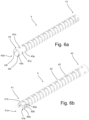
- Each intermediate segment 42 is cylindrically disc-shaped with an outer circumferentially extending side wall, so that the bending section 4 has a substantially uniform outer diameter.
- the proximal end 4a of the proximal end segment 43 has a slightly larger outer diameter.
- a sleeve or an external sheath may generally be provided to enclose the intermediate segments 42.
- the sleeve or external sheath provides the bending section 4 with a smooth outer surface without gaps which is suitable for insertion into a body cavity. However, the sleeve is omitted here for illustration purposes.
- the through holes 91a, 91b are instead depressions formed in the inner surface of the circumferentially extending side wall 43b of the proximal end segment 43.
- the adhesive 8 is injected in the small gap between the inner surface of the side wall 43b of the proximal end segment 43 and the outer surface 7c of the side wall 7a of the flexible tube 7.
- the tip part 5 comprises a bending section 4, a cap 6, and a flexible tube 7.
- the bending section 4 comprises a plurality of hingedly interconnected segments including a distal end segment 41, a proximal end segment 43, and a number of intermediate segments 42 positioned between the proximal end segment 43 and the distal end segment 41.
- the number of intermediate segments 42 is 18, but may in principle be less or even greater.
- the bending section 4 is formed in one piece of polyoxymethylene (POM).
- POM polyoxymethylene
Landscapes
- Health & Medical Sciences (AREA)
- Life Sciences & Earth Sciences (AREA)
- Surgery (AREA)
- Engineering & Computer Science (AREA)
- Heart & Thoracic Surgery (AREA)
- Biophysics (AREA)
- Veterinary Medicine (AREA)
- Public Health (AREA)
- General Health & Medical Sciences (AREA)
- Animal Behavior & Ethology (AREA)
- Biomedical Technology (AREA)
- Medical Informatics (AREA)
- Physics & Mathematics (AREA)
- Molecular Biology (AREA)
- Radiology & Medical Imaging (AREA)
- Pathology (AREA)
- Optics & Photonics (AREA)
- Nuclear Medicine, Radiotherapy & Molecular Imaging (AREA)
- Manufacturing & Machinery (AREA)
- Pulmonology (AREA)
- Anesthesiology (AREA)
- Hematology (AREA)
- Rehabilitation Therapy (AREA)
- Endoscopes (AREA)
Claims (15)
- Partie de tête articulée flexible (5) pour un endoscope, la partie de tête articulée flexible (5) comprenant :une section de flexion (4) comportant un certain nombre de segments reliés par charnières, dont un segment d'extrémité proximale (43), un segment d'extrémité distale (41) et une pluralité de segments intermédiaires (42) positionnés entre le segment d'extrémité proximale et le segment d'extrémité distale, etun tube flexible (7) ayant une extrémité proximale et une extrémité distale, le segment d'extrémité proximale de la section de flexion comprenant un certain nombre d'au moins un creux ou trou traversant (91) ménagés dans une paroi latérale extérieure s'étendant de manière circonférentielle du segment d'extrémité proximale, la paroi latérale enfermant un espace du segment d'extrémité proximale, un adhésif durci adhérant au moins à une surface extérieure du tube flexible et s'étendant dans l'au moins un creux ou trou traversant, de telle sorte l'adhésif durci dans l'au moins un creux ou trou traversant forme un cran afin de fixer le segment d'extrémité proximal au tube flexible, caractérisé en ce que le segment d'extrémité proximale a au moins trois nervures de centrage (43f) sur une surface intérieure de la paroi latérale extérieure du segment d'extrémité proximale, les nervures centrales étant positionnées de façon à buter contre une surface extérieure de l'extrémité distale du tube flexible afin de centrer le tube flexible dans l'espace du segment d'extrémité proximale.
- Partie de tête articulée flexible selon la revendication 1, dans laquelle le segment d'extrémité proximale comprend un premier ensemble de connexion incluant un certain nombre de creux ou trous traversants, le premier ensemble de connexion étant ménagé dans une paroi latérale extérieure s'étendant de manière circonférentielle du segment d'extrémité proximale, un adhésif durci adhérant au moins à une surface du tube flexible de la partie de tête et s'étendant dans le premier ensemble de connexion, de telle sorte l'adhésif durci dans le premier ensemble de connexion forme un cran afin de fixer le segment d'extrémité proximal au tube flexible.
- Partie de tête articulée flexible selon la revendication 1 ou 2, comprenant en outre un capot, dans laquelle le segment d'extrémité distale comprend un deuxième ensemble de connexion incluant un certain nombre de creux ou trous traversants, le deuxième ensemble de connexion étant ménagé dans une paroi latérale extérieure s'étendant de manière circonférentielle du segment d'extrémité distale, un adhésif durci adhérant au moins à une surface du capot de la partie de tête et s'étendant dans le deuxième ensemble de connexion, de telle sorte l'adhésif durci dans le deuxième ensemble de connexion forme un cran afin de fixer le segment d'extrémité distale au capot.
- Partie de tête articulée flexible selon l'une quelconque des revendications précédentes, dans laquelle l'adhésif durci dans l'ensemble de connexion forme un engagement positif ou une connexion positive pour fixer le segment d'extrémité proximale au tube flexible, en empêchant éventuellement un mouvement axial entre le tube flexible et le segment d'extrémité proximale.
- Partie de tête articulée flexible selon l'une quelconque des revendications précédentes, dans laquelle le tube flexible et le segment d'extrémité proximale sont positionnés à côté l'un de l'autre.
- Partie de tête articulée flexible selon l'une quelconque des revendications précédentes, dans laquelle le tube flexible et le segment d'extrémité proximale sont positionnés en chevauchement, et l'ensemble de connexion est en communication, éventuellement en communication directe, avec le chevauchement ou est positionné à côté du chevauchement.
- Partie de tête articulée flexible selon la revendication 2, dans laquelle l'ensemble de connexion comprend au moins un groupe d'au moins deux creux ou trous traversants qui sont interconnectés par un évidement ménagé dans la paroi latérale extérieure s'étendant de manière circonférentielle du segment d'extrémité proximale, l'adhésif durci adhérant au moins à la surface du tube flexible et s'étendant de la surface jusque dans chaque groupe respectif de creux ou trous traversants de l'ensemble de connexion et dans l'évidement interconnectant le groupe respectif, pour ainsi un ancrage afin de fixer le segment d'extrémité proximale au tube flexible.
- Partie de tête articulée flexible selon l'une quelconque des revendications précédentes, dans laquelle le nombre de segments intermédiaires est d'au moins 8, 9, 10, 11, 12, 13, 14, 15, 16, 17, 18, 19, 20, 21, 22, 23, 24, 25, 26, 27, 28, 29 ou 30.
- Partie de tête articulée flexible selon l'une quelconque des revendications précédentes, dans laquelle le segment d'extrémité proximale enferme ou entoure le tube flexible.
- Partie de tête articulée flexible selon l'une quelconque des revendications précédentes, dans laquelle la section de flexion comprend les éléments suivants, ou en est essentiellement constituée : polypropylene (PP), polyethylene (PE) ou polyoxymethylene (POM).
- Partie de tête articulée flexible selon l'une quelconque des revendications précédentes, dans laquelle le segment d'extrémité proximale a quatre nervures de centrage sur la surface intérieure de la paroi latérale extérieure du segment d'extrémité proximale, les nervures de centrage étant positionnées de façon à buter sur une surface extérieure de l'extrémité distale du tube flexible afin de centrer le tube flexible dans l'espace du segment d'extrémité proximale.
- Partie de tête articulée flexible selon l'une quelconque des revendications précédentes, dans laquelle au moins l'un, éventuellement la totalité, du nombre de creux ou trous traversants de l'ensemble de connexion a un bord non tranchant, de préférence un bord arrondi, un bord biseauté ou un bord chanfreiné.
- Endoscope comprenant une partie de tête articulée flexible selon l'une quelconque des revendications précédentes.
- Système permettant l'inspection visuelle d'endroits inaccessibles tels que des cavités corporelles humaines, le système comprenant :
un endoscope selon la revendication 13 et un écran, l'endoscope pouvant être connecté à l'écran, et l'écran permettant à un opérateur de voir une image capturée par l'ensemble de caméra de l'endoscope. - Procédé de fixation d'une section de flexion à un tube flexible pour au moins partiellement assembler une partie de tête articulée flexible selon l'une quelconque des revendications 1 à 12, le procédé comprenant les étapes consistant à :a. fournir une section de flexion comportant un certain nombre de segments reliés par charnières, dont un segment d'extrémité proximale, un segment d'extrémité distale et une pluralité de segments intermédiaires positionnés entre le segment d'extrémité proximale et le segment d'extrémité distale, le segment d'extrémité proximale comprenant un certain nombre d'au moins un creux ou trou traversant ménagés dans une paroi latérale extérieure s'étendant de manière circonférentielle du segment d'extrémité proximale, la paroi latérale enfermant un espace du segment d'extrémité proximale, le segment d'extrémité proximale ayant au moins trois nervures de centrage sur une surface intérieure de la paroi latérale extérieure du segment d'extrémité proximale ;b. fournir un tube flexible ayant une extrémité proximale et une extrémité distale ;b1. insérer l'extrémité distale du tube flexible dans le segment d'extrémité proximale, les nervures de centrage étant positionnées de façon à buter contre une surface extérieure de l'extrémité distale du tube flexible afin de centrer le tube flexible dans l'espace du segment d'extrémité proximale ;c. injecter un adhésif dans l'au moins un creux ou trou traversant et en contact avec une surface du tube flexible ; etd. permettre ou provoquer le durcissement de l'adhésif, de façon que l'adhésif durci forme un cran adhérant au moins au tube flexible afin de fixer le segment d'extrémité proximale au tube flexible.
Priority Applications (4)
| Application Number | Priority Date | Filing Date | Title |
|---|---|---|---|
| EP18215278.5A EP3669744B1 (fr) | 2018-12-21 | 2018-12-21 | Partie de pointe articulée pour un endoscope |
| CN201910987848.0A CN111345769A (zh) | 2018-12-21 | 2019-10-17 | 用于内窥镜的铰接式尖端部分 |
| US16/718,335 US11992181B2 (en) | 2018-12-21 | 2019-12-18 | Articulated tip part for an endoscope |
| US16/874,628 US12349869B2 (en) | 2018-12-21 | 2020-05-14 | Articulated tip part for an endoscope |
Applications Claiming Priority (1)
| Application Number | Priority Date | Filing Date | Title |
|---|---|---|---|
| EP18215278.5A EP3669744B1 (fr) | 2018-12-21 | 2018-12-21 | Partie de pointe articulée pour un endoscope |
Publications (2)
| Publication Number | Publication Date |
|---|---|
| EP3669744A1 EP3669744A1 (fr) | 2020-06-24 |
| EP3669744B1 true EP3669744B1 (fr) | 2025-07-09 |
Family
ID=65023648
Family Applications (1)
| Application Number | Title | Priority Date | Filing Date |
|---|---|---|---|
| EP18215278.5A Active EP3669744B1 (fr) | 2018-12-21 | 2018-12-21 | Partie de pointe articulée pour un endoscope |
Country Status (3)
| Country | Link |
|---|---|
| US (1) | US11992181B2 (fr) |
| EP (1) | EP3669744B1 (fr) |
| CN (1) | CN111345769A (fr) |
Families Citing this family (9)
| Publication number | Priority date | Publication date | Assignee | Title |
|---|---|---|---|---|
| WO2019002186A1 (fr) | 2017-06-26 | 2019-01-03 | Ambu A/S | Section de courbure destinée à un endoscope |
| US12349869B2 (en) | 2018-12-21 | 2025-07-08 | Ambu A/S | Articulated tip part for an endoscope |
| EP4035584B1 (fr) * | 2021-01-28 | 2023-10-18 | Ambu A/S | Endoscope comprenant un corps de section de flexion articulé |
| EP4162860A1 (fr) | 2021-10-08 | 2023-04-12 | Ambu A/S | Endoscope |
| EP4190224A1 (fr) | 2021-12-01 | 2023-06-07 | Ambu A/S | Poignée d'endoscope dotée d'un cadre |
| CN217040070U (zh) * | 2021-12-07 | 2022-07-26 | 广州瑞派医疗器械有限责任公司 | 先端头蛇骨连接结构及内窥镜 |
| CN217040075U (zh) * | 2021-12-07 | 2022-07-26 | 广州瑞派医疗器械有限责任公司 | 蛇骨插入管连接结构及内窥镜 |
| EP4233679A1 (fr) | 2022-02-23 | 2023-08-30 | Ambu A/S | Endoscope comprenant une section de flexion ayant des lumens de fil de guidage déplacés |
| DE102022107674A1 (de) * | 2022-03-30 | 2023-10-05 | Olympus Winter & Ibe Gmbh | Endoskop und verfahren zur herstellung einer abgedichteten einheit eines endoskops |
Family Cites Families (126)
| Publication number | Priority date | Publication date | Assignee | Title |
|---|---|---|---|---|
| US4778247A (en) | 1984-05-04 | 1988-10-18 | Warner Lambert Technologies, Inc. | Molded objective head for fiberscopes with integral lenses |
| US4651718A (en) | 1984-06-29 | 1987-03-24 | Warner-Lambert Technologies Inc. | Vertebra for articulatable shaft |
| US4580551A (en) | 1984-11-02 | 1986-04-08 | Warner-Lambert Technologies, Inc. | Flexible plastic tube for endoscopes and the like |
| JPH0434499Y2 (fr) | 1985-08-26 | 1992-08-17 | ||
| JPS6365840A (ja) | 1986-04-04 | 1988-03-24 | オリンパス光学工業株式会社 | 内視鏡 |
| US4832003A (en) | 1986-09-12 | 1989-05-23 | Olympus Optical Co., Ltd. | Electronic endoscope tip |
| US4856495A (en) | 1986-09-25 | 1989-08-15 | Olympus Optical Co., Ltd. | Endoscope apparatus |
| US4841952A (en) | 1986-11-06 | 1989-06-27 | Olympus Optical Co., Ltd. | Endoscope with an optical system |
| US4918521A (en) | 1987-01-20 | 1990-04-17 | Olympus Optical Co., Ltd. | Solid state imaging apparatus |
| JPH069540B2 (ja) | 1987-04-03 | 1994-02-09 | オリンパス光学工業株式会社 | 内視鏡 |
| US4860732A (en) | 1987-11-25 | 1989-08-29 | Olympus Optical Co., Ltd. | Endoscope apparatus provided with endoscope insertion aid |
| US4911148A (en) | 1989-03-14 | 1990-03-27 | Intramed Laboratories, Inc. | Deflectable-end endoscope with detachable flexible shaft assembly |
| JPH03128028A (ja) | 1989-10-13 | 1991-05-31 | Machida Seisakusho:Kk | 湾曲操作装置用アングル |
| US5089895A (en) | 1990-05-07 | 1992-02-18 | Cues, Inc. | Encapsulated television camera and method and apparatus for fabricating same |
| US5418566A (en) | 1990-09-10 | 1995-05-23 | Kabushiki Kaisha Toshiba | Compact imaging apparatus for electronic endoscope with improved optical characteristics |
| US5251611A (en) | 1991-05-07 | 1993-10-12 | Zehel Wendell E | Method and apparatus for conducting exploratory procedures |
| DE4129961C2 (de) | 1991-09-10 | 1996-02-15 | Wolf Gmbh Richard | Videoendoskop mit Festkörperbildaufnahmevorrichtung |
| JP3181331B2 (ja) | 1991-10-04 | 2001-07-03 | 株式会社町田製作所 | 内視鏡 |
| US5380301A (en) | 1992-07-10 | 1995-01-10 | Sherwood Medical Company | Catheter/hub strain relief and method of manufacture thereof |
| US5379756A (en) | 1992-09-11 | 1995-01-10 | Welch Allyn, Inc. | Replaceable lens assembly for video laparoscope |
| US5879288A (en) | 1992-11-25 | 1999-03-09 | Olympus Optical Co., Ltd. | Endoscope system including both reusable-type and cover-type endoscopes |
| JPH06189898A (ja) | 1992-12-25 | 1994-07-12 | Olympus Optical Co Ltd | 内視鏡用チャンネルチューブ |
| JP3372980B2 (ja) | 1993-01-22 | 2003-02-04 | オリンパス光学工業株式会社 | 内視鏡 |
| US5438975A (en) | 1993-03-24 | 1995-08-08 | Machida Endoscope Co., Ltd. | Distal tip of endoscope having spirally coiled control wires |
| JP2948722B2 (ja) * | 1993-09-17 | 1999-09-13 | 富士写真光機株式会社 | 内視鏡先端部接続構造 |
| US6184923B1 (en) | 1994-11-25 | 2001-02-06 | Olympus Optical Co., Ltd. | Endoscope with an interchangeable distal end optical adapter |
| JP3500219B2 (ja) | 1995-03-03 | 2004-02-23 | オリンパス株式会社 | 内視鏡 |
| US6004263A (en) | 1996-03-13 | 1999-12-21 | Hihon Kohden Corporation | Endoscope with detachable operation unit and insertion unit |
| US6078830A (en) | 1997-10-01 | 2000-06-20 | Ep Technologies, Inc. | Molded catheter distal end assembly and process for the manufacture thereof |
| US20040044350A1 (en) | 1999-04-09 | 2004-03-04 | Evalve, Inc. | Steerable access sheath and methods of use |
| DE19924440A1 (de) | 1999-05-28 | 2000-12-07 | Storz Karl Gmbh & Co Kg | Schaft für ein flexibles Endoskop |
| US6302616B1 (en) | 1999-09-01 | 2001-10-16 | Olympus Optical Co., Ltd. | Rotation mechanism including rotation shaft and fixed member with welding structure, and producing method of the same |
| DE10102433B4 (de) | 2000-01-21 | 2008-07-10 | Pentax Corp. | Flexibles Rohr für ein Endoskop |
| JP3736269B2 (ja) | 2000-03-23 | 2006-01-18 | フジノン株式会社 | 内視鏡の軟性部−アングル部連結構造 |
| US6468203B2 (en) | 2000-04-03 | 2002-10-22 | Neoguide Systems, Inc. | Steerable endoscope and improved method of insertion |
| JP3602803B2 (ja) | 2001-01-30 | 2004-12-15 | オリンパス株式会社 | 内視鏡湾曲管部の外皮の製造方法 |
| US20060178556A1 (en) | 2001-06-29 | 2006-08-10 | Intuitive Surgical, Inc. | Articulate and swapable endoscope for a surgical robot |
| JP2003107370A (ja) | 2001-09-27 | 2003-04-09 | Fuji Photo Optical Co Ltd | 内視鏡の先端光学部品の製造方法 |
| US20050226682A1 (en) | 2001-10-09 | 2005-10-13 | David Chersky | Method and apparatus for improved stiffness in the linkage assembly of a flexible arm |
| US6991603B2 (en) | 2002-05-17 | 2006-01-31 | Optim, Inc. | Insertion tube device |
| US6821284B2 (en) | 2003-01-22 | 2004-11-23 | Novare Surgical Systems, Inc. | Surgical clamp inserts with micro-tractive surfaces |
| US20050154262A1 (en) | 2003-04-01 | 2005-07-14 | Banik Michael S. | Imaging system for video endoscope |
| US8118732B2 (en) | 2003-04-01 | 2012-02-21 | Boston Scientific Scimed, Inc. | Force feedback control system for video endoscope |
| US7591783B2 (en) | 2003-04-01 | 2009-09-22 | Boston Scientific Scimed, Inc. | Articulation joint for video endoscope |
| US20040199052A1 (en) | 2003-04-01 | 2004-10-07 | Scimed Life Systems, Inc. | Endoscopic imaging system |
| US20070225555A1 (en) | 2003-05-16 | 2007-09-27 | David Stefanchik | Method for deploying a medical device |
| US7410483B2 (en) * | 2003-05-23 | 2008-08-12 | Novare Surgical Systems, Inc. | Hand-actuated device for remote manipulation of a grasping tool |
| JP2005013708A (ja) | 2003-05-30 | 2005-01-20 | Olympus Corp | 内視鏡及びその組立方法 |
| EP1661505B1 (fr) * | 2003-09-05 | 2014-12-31 | Olympus Corporation | Endoscope |
| US7645229B2 (en) | 2003-09-26 | 2010-01-12 | Armstrong David N | Instrument and method for endoscopic visualization and treatment of anorectal fistula |
| JP4409258B2 (ja) | 2003-11-20 | 2010-02-03 | オリンパス株式会社 | カプセル型内視鏡およびその製造方法 |
| EP1694489B1 (fr) | 2003-12-10 | 2016-06-22 | William A. Cook Australia Pty. Ltd. | Moulage par injection de cavités fonctionnelles |
| JP2005177025A (ja) | 2003-12-17 | 2005-07-07 | Olympus Corp | 内視鏡 |
| US7708688B2 (en) | 2004-03-15 | 2010-05-04 | Paradigm Optics, Incorporated | Polymer endoscopic shaft |
| US20050234499A1 (en) | 2004-04-19 | 2005-10-20 | Scimed Life Systems, Inc. | Multi-lumen balloon catheter including manifold |
| US9089258B2 (en) | 2004-04-21 | 2015-07-28 | Acclarent, Inc. | Endoscopic methods and devices for transnasal procedures |
| US7678117B2 (en) | 2004-06-07 | 2010-03-16 | Novare Surgical Systems, Inc. | Articulating mechanism with flex-hinged links |
| JPWO2006013860A1 (ja) | 2004-08-03 | 2008-05-01 | オリンパス株式会社 | 医療機器封止用樹脂組成物及びそれにより封止された内視鏡用医療機器 |
| US8182422B2 (en) | 2005-12-13 | 2012-05-22 | Avantis Medical Systems, Inc. | Endoscope having detachable imaging device and method of using |
| WO2006086106A2 (fr) | 2005-01-10 | 2006-08-17 | Perceptron, Inc. | Multicable optique |
| JP2006218102A (ja) * | 2005-02-10 | 2006-08-24 | Olympus Corp | 内視鏡装置 |
| JP4477519B2 (ja) | 2005-02-14 | 2010-06-09 | オリンパス株式会社 | 内視鏡 |
| US20060235458A1 (en) | 2005-04-15 | 2006-10-19 | Amir Belson | Instruments having an external working channel |
| KR100596457B1 (ko) | 2005-06-27 | 2006-07-04 | 이성용 | 내시경을 포함하는 카메라 영상장치 |
| KR100761387B1 (ko) | 2005-07-13 | 2007-09-27 | 서울반도체 주식회사 | 몰딩부재를 형성하기 위한 몰드 및 그것을 사용한 몰딩부재형성방법 |
| JP2007054125A (ja) | 2005-08-22 | 2007-03-08 | Olympus Medical Systems Corp | 内視鏡 |
| US8052597B2 (en) | 2005-08-30 | 2011-11-08 | Boston Scientific Scimed, Inc. | Method for forming an endoscope articulation joint |
| EP1927312A1 (fr) | 2005-09-22 | 2008-06-04 | Olympus Corporation | Partie d'insertion d'endoscope |
| US8500628B2 (en) | 2006-02-28 | 2013-08-06 | Olympus Endo Technology America, Inc. | Rotate-to-advance catheterization system |
| US7955255B2 (en) * | 2006-04-20 | 2011-06-07 | Boston Scientific Scimed, Inc. | Imaging assembly with transparent distal cap |
| JP4728162B2 (ja) | 2006-04-21 | 2011-07-20 | オリンパスメディカルシステムズ株式会社 | 内視鏡システム |
| JP4731606B2 (ja) | 2006-06-08 | 2011-07-27 | サージカル・ソルーシヨンズ・エルエルシー | 関節連結シャフトを有する医療デバイス |
| JP2008110071A (ja) | 2006-10-30 | 2008-05-15 | Olympus Corp | 内視鏡の湾曲部構造 |
| US9326665B2 (en) | 2007-01-09 | 2016-05-03 | Medtronic Xomed, Inc. | Surgical instrument, system, and method for biofilm removal |
| JP2008259634A (ja) * | 2007-04-11 | 2008-10-30 | Olympus Corp | 内視鏡用可撓管と環状連結部材との連結構造 |
| US8657805B2 (en) | 2007-05-08 | 2014-02-25 | Intuitive Surgical Operations, Inc. | Complex shape steerable tissue visualization and manipulation catheter |
| WO2008144401A1 (fr) | 2007-05-18 | 2008-11-27 | Boston Scientific Scimed, Inc. | Dispositif creux articulé pouvant être tordu |
| US8864675B2 (en) | 2007-06-28 | 2014-10-21 | W. L. Gore & Associates, Inc. | Catheter |
| US20090054728A1 (en) | 2007-08-21 | 2009-02-26 | Trusty Robert M | Manipulatable guide system and methods for natural orifice translumenal endoscopic surgery |
| CN101815476A (zh) | 2007-08-27 | 2010-08-25 | 脊柱诊察公司 | 用于进入和察看脊柱的囊袋套管系统及相关方法 |
| JP2009119064A (ja) | 2007-11-15 | 2009-06-04 | Olympus Corp | カバー式内視鏡、カバー用内視鏡および内視鏡カバー |
| JP2009125389A (ja) | 2007-11-26 | 2009-06-11 | Olympus Corp | 内視鏡 |
| GB2456165A (en) | 2008-01-04 | 2009-07-08 | Gyrus Medical Ltd | Slotted, flexible shaft for an endoscopic instrument |
| EP2249690B1 (fr) | 2008-02-06 | 2021-09-29 | Intuitive Surgical Operations, Inc. | Instrument segmenté ayant des capacités de freinage |
| JP4584357B2 (ja) | 2008-12-09 | 2010-11-17 | オリンパスメディカルシステムズ株式会社 | カプセル型医療装置およびその製造方法 |
| RU2510234C2 (ru) | 2008-12-10 | 2014-03-27 | Амбу А/С | Эндоскоп, имеющий корпус камеры, и способ изготовления корпуса камеры |
| JP2012511355A (ja) | 2008-12-10 | 2012-05-24 | アンブ・エ/エス | 使い捨て部分を有するイメージングシステム |
| JP2012512670A (ja) | 2008-12-10 | 2012-06-07 | アンブ・エ/エス | 屈曲部分を有する内視鏡 |
| WO2010066789A1 (fr) | 2008-12-10 | 2010-06-17 | Ambu A/S | Mécanisme de commande de section de courbure d'endoscope |
| US20110034771A1 (en) | 2009-08-07 | 2011-02-10 | Gyrus Acmi, Inc. | Endoscope resilient deflection section frame |
| JP4813627B2 (ja) | 2009-10-14 | 2011-11-09 | オリンパスメディカルシステムズ株式会社 | 医療用可撓管と医療機器の挿入部 |
| US8747303B2 (en) | 2009-11-02 | 2014-06-10 | Hoya Corporation | Method for affixing endoscope curved section protective sheath |
| US9795765B2 (en) | 2010-04-09 | 2017-10-24 | St. Jude Medical International Holding S.À R.L. | Variable stiffness steering mechanism for catheters |
| KR20120002117A (ko) | 2010-06-30 | 2012-01-05 | 삼성전자주식회사 | 관리 서버 및 그 관리 방법 |
| DK201001052A (en) | 2010-11-19 | 2011-11-10 | Ambu As | A tracheal intubation guide |
| KR101180820B1 (ko) | 2010-11-25 | 2012-09-07 | 한국과학기술원 | 플렉시블 튜브의 형상 잠금장치 |
| TWM421800U (en) | 2011-08-05 | 2012-02-01 | Limit Optics Co Ltd | Endoscope device having flexible printed circuit board |
| US9622649B2 (en) | 2011-08-05 | 2017-04-18 | Ambu A/S | Endoscope with a T-shaped flexible circuit board |
| EP2809219B1 (fr) * | 2012-01-31 | 2020-01-22 | Boston Scientific Scimed, Inc. | Systèmes de fixation de sections de dispositif médical |
| JP5490838B2 (ja) * | 2012-03-14 | 2014-05-14 | 富士フイルム株式会社 | 内視鏡挿入部及びその接合方法 |
| WO2013183353A1 (fr) * | 2012-06-06 | 2013-12-12 | オリンパスメディカルシステムズ株式会社 | Endoscope |
| US10039440B2 (en) * | 2012-06-11 | 2018-08-07 | Intuitive Surgical Operations, Inc. | Systems and methods for cleaning a minimally invasive instrument |
| WO2014106510A1 (fr) | 2013-01-07 | 2014-07-10 | Ambu A/S | Boîtier de caméra d'endoscope comprenant un évidemment de guidage |
| US10321804B2 (en) * | 2013-01-07 | 2019-06-18 | Ambu A/S | Articulated tip part for an endoscope |
| EP2958480A1 (fr) | 2013-02-22 | 2015-12-30 | Ambu A/S | Moyen pour maintenir un fil de traction tendu dans un endoscope |
| US9144370B2 (en) | 2013-02-28 | 2015-09-29 | Canon Usa Inc. | Mechanical structure of articulated sheath |
| EP2837324B1 (fr) | 2013-03-05 | 2017-03-15 | Olympus Corporation | Endoscope |
| US10149955B2 (en) | 2013-06-20 | 2018-12-11 | Ambu A/S | Laryngeal mask |
| US9730755B2 (en) | 2014-01-31 | 2017-08-15 | Medtronic Cryocath Lp | Medical device with adjustable flexibility |
| JP5945633B2 (ja) * | 2014-02-13 | 2016-07-05 | オリンパス株式会社 | 挿入機器 |
| JP5901859B1 (ja) * | 2014-04-15 | 2016-04-13 | オリンパス株式会社 | 内視鏡用湾曲管、内視鏡および内視鏡用湾曲管の製造方法 |
| JP6238836B2 (ja) * | 2014-05-29 | 2017-11-29 | オリンパス株式会社 | 光ファイバスキャナ、照明装置および観察装置 |
| JP5945650B1 (ja) | 2014-09-11 | 2016-07-05 | オリンパス株式会社 | インサート成形品、該インサート成形品を用いた機器及びインサート成形品の製造方法 |
| US9459442B2 (en) | 2014-09-23 | 2016-10-04 | Scott Miller | Optical coupler for optical imaging visualization device |
| CN107735009B (zh) | 2015-05-27 | 2019-09-03 | 安布股份有限公司 | 内窥镜 |
| WO2016188538A1 (fr) | 2015-05-27 | 2016-12-01 | Ambu A/S | Endoscope comprenant un châssis à structure de coque |
| CN107809941B (zh) | 2015-05-27 | 2020-05-12 | 安布股份有限公司 | 内窥镜 |
| WO2016188539A1 (fr) | 2015-05-27 | 2016-12-01 | Ambu A/S | Endoscope |
| WO2016188537A1 (fr) | 2015-05-27 | 2016-12-01 | Ambu A/S | Endoscope |
| CN107809939B (zh) | 2015-05-27 | 2020-09-08 | 安布股份有限公司 | 具有工具的内窥镜 |
| WO2017122330A1 (fr) | 2016-01-14 | 2017-07-20 | オリンパス株式会社 | Dispositif de mesure de forme souple tubulaire |
| WO2018059642A2 (fr) | 2016-09-28 | 2018-04-05 | Ambu A/S | Endoscope conçu pour faciliter des procédures bal |
| EP3613330B1 (fr) * | 2017-04-19 | 2024-02-28 | Hoya Corporation | Dispositif de fixation pour partie d'extrémité d'endoscope |
| WO2019002186A1 (fr) | 2017-06-26 | 2019-01-03 | Ambu A/S | Section de courbure destinée à un endoscope |
| EP3628205A1 (fr) | 2018-09-28 | 2020-04-01 | Ambu A/S | Procédé de fabrication d'une partie de pointe et partie de pointe pour un endoscope |
| EP3705019A1 (fr) | 2019-03-04 | 2020-09-09 | Ambu A/S | Partie de pointe pour endoscope |
-
2018
- 2018-12-21 EP EP18215278.5A patent/EP3669744B1/fr active Active
-
2019
- 2019-10-17 CN CN201910987848.0A patent/CN111345769A/zh active Pending
- 2019-12-18 US US16/718,335 patent/US11992181B2/en active Active
Also Published As
| Publication number | Publication date |
|---|---|
| CN111345769A (zh) | 2020-06-30 |
| US11992181B2 (en) | 2024-05-28 |
| EP3669744A1 (fr) | 2020-06-24 |
| US20200196835A1 (en) | 2020-06-25 |
Similar Documents
| Publication | Publication Date | Title |
|---|---|---|
| EP3669744B1 (fr) | Partie de pointe articulée pour un endoscope | |
| US11622674B2 (en) | Articulated tip part for an endoscope | |
| US12349869B2 (en) | Articulated tip part for an endoscope | |
| US11794389B2 (en) | Tip part assembly for an endoscope | |
| US12185922B2 (en) | Tip part for a videoscope and a videoscope including said tip part | |
| EP2596738B1 (fr) | Endoscope | |
| EP3628205A1 (fr) | Procédé de fabrication d'une partie de pointe et partie de pointe pour un endoscope | |
| US20070244354A1 (en) | Vibratory Device, Endoscope Having Such A Device, Method For Configuring An Endoscope, And Method Of Reducing Looping Of An Endoscope. | |
| EP3628206B1 (fr) | Procédé de fabrication d'une partie de pointe et partie de pointe pour endoscope | |
| US11471031B2 (en) | Articulated tip part for an endoscope | |
| JP2013526323A (ja) | 喉頭鏡、喉頭鏡アーム、およびそれらの製造方法 | |
| EP4132341B1 (fr) | Embouts distaux pour dispositifs médicaux | |
| JP6811720B2 (ja) | 内視鏡、内視鏡用キャップ及び内視鏡用キャップ形成方法 | |
| CN118019481A (zh) | 内窥镜 | |
| EP3669746A1 (fr) | Partie de pointe articulée pour un endoscope | |
| US20220296077A1 (en) | Insertion apparatus and endoscope | |
| CN112450853A (zh) | 用于内窥镜的端头部组件 | |
| EP3788939B1 (fr) | Ensemble de partie de pointe pour endoscope et un procede de fabrication d'un ensemble de partie de pointe pour endoscope | |
| JP4652843B2 (ja) | 内視鏡 | |
| JP6850694B2 (ja) | 内視鏡及び内視鏡の製造方法 | |
| JP6219011B1 (ja) | 内視鏡 | |
| JP4564531B2 (ja) | 回転自走式内視鏡装置 | |
| EP4179951A1 (fr) | Bouton de commutation pour endoscope | |
| JP3188382U (ja) | 内視鏡 | |
| HK1183221A (en) | Laryngoscopes, laryngoscope arms and methods of manufacture |
Legal Events
| Date | Code | Title | Description |
|---|---|---|---|
| PUAI | Public reference made under article 153(3) epc to a published international application that has entered the european phase |
Free format text: ORIGINAL CODE: 0009012 |
|
| STAA | Information on the status of an ep patent application or granted ep patent |
Free format text: STATUS: THE APPLICATION HAS BEEN PUBLISHED |
|
| AK | Designated contracting states |
Kind code of ref document: A1 Designated state(s): AL AT BE BG CH CY CZ DE DK EE ES FI FR GB GR HR HU IE IS IT LI LT LU LV MC MK MT NL NO PL PT RO RS SE SI SK SM TR |
|
| AX | Request for extension of the european patent |
Extension state: BA ME |
|
| STAA | Information on the status of an ep patent application or granted ep patent |
Free format text: STATUS: REQUEST FOR EXAMINATION WAS MADE |
|
| 17P | Request for examination filed |
Effective date: 20201209 |
|
| RBV | Designated contracting states (corrected) |
Designated state(s): AL AT BE BG CH CY CZ DE DK EE ES FI FR GB GR HR HU IE IS IT LI LT LU LV MC MK MT NL NO PL PT RO RS SE SI SK SM TR |
|
| STAA | Information on the status of an ep patent application or granted ep patent |
Free format text: STATUS: EXAMINATION IS IN PROGRESS |
|
| 17Q | First examination report despatched |
Effective date: 20221128 |
|
| GRAP | Despatch of communication of intention to grant a patent |
Free format text: ORIGINAL CODE: EPIDOSNIGR1 |
|
| STAA | Information on the status of an ep patent application or granted ep patent |
Free format text: STATUS: GRANT OF PATENT IS INTENDED |
|
| INTG | Intention to grant announced |
Effective date: 20250210 |
|
| GRAS | Grant fee paid |
Free format text: ORIGINAL CODE: EPIDOSNIGR3 |
|
| GRAA | (expected) grant |
Free format text: ORIGINAL CODE: 0009210 |
|
| STAA | Information on the status of an ep patent application or granted ep patent |
Free format text: STATUS: THE PATENT HAS BEEN GRANTED |
|
| AK | Designated contracting states |
Kind code of ref document: B1 Designated state(s): AL AT BE BG CH CY CZ DE DK EE ES FI FR GB GR HR HU IE IS IT LI LT LU LV MC MK MT NL NO PL PT RO RS SE SI SK SM TR |
|
| REG | Reference to a national code |
Ref country code: GB Ref legal event code: FG4D |
|
| REG | Reference to a national code |
Ref country code: CH Ref legal event code: EP |
|
| REG | Reference to a national code |
Ref country code: IE Ref legal event code: FG4D |
|
| REG | Reference to a national code |
Ref country code: DE Ref legal event code: R096 Ref document number: 602018083376 Country of ref document: DE |
|
| REG | Reference to a national code |
Ref country code: NL Ref legal event code: MP Effective date: 20250709 |
|
| PG25 | Lapsed in a contracting state [announced via postgrant information from national office to epo] |
Ref country code: PT Free format text: LAPSE BECAUSE OF FAILURE TO SUBMIT A TRANSLATION OF THE DESCRIPTION OR TO PAY THE FEE WITHIN THE PRESCRIBED TIME-LIMIT Effective date: 20251110 |
|
| PG25 | Lapsed in a contracting state [announced via postgrant information from national office to epo] |
Ref country code: NL Free format text: LAPSE BECAUSE OF FAILURE TO SUBMIT A TRANSLATION OF THE DESCRIPTION OR TO PAY THE FEE WITHIN THE PRESCRIBED TIME-LIMIT Effective date: 20250709 |
|
| REG | Reference to a national code |
Ref country code: AT Ref legal event code: MK05 Ref document number: 1811004 Country of ref document: AT Kind code of ref document: T Effective date: 20250709 |