EP3658564B1 - Complexes métalliques - Google Patents
Complexes métalliques Download PDFInfo
- Publication number
- EP3658564B1 EP3658564B1 EP18740862.0A EP18740862A EP3658564B1 EP 3658564 B1 EP3658564 B1 EP 3658564B1 EP 18740862 A EP18740862 A EP 18740862A EP 3658564 B1 EP3658564 B1 EP 3658564B1
- Authority
- EP
- European Patent Office
- Prior art keywords
- formula
- group
- groups
- carbon atoms
- cyc
- Prior art date
- Legal status (The legal status is an assumption and is not a legal conclusion. Google has not performed a legal analysis and makes no representation as to the accuracy of the status listed.)
- Active
Links
- 229910052751 metal Inorganic materials 0.000 title claims description 43
- 239000002184 metal Substances 0.000 title claims description 43
- 125000004432 carbon atom Chemical group C* 0.000 claims description 131
- 239000003446 ligand Substances 0.000 claims description 125
- 125000003118 aryl group Chemical group 0.000 claims description 103
- 150000001875 compounds Chemical class 0.000 claims description 67
- -1 iridium alkoxides Chemical class 0.000 claims description 65
- 229910052799 carbon Inorganic materials 0.000 claims description 49
- 229910052757 nitrogen Inorganic materials 0.000 claims description 45
- 229910052741 iridium Inorganic materials 0.000 claims description 44
- 239000011159 matrix material Substances 0.000 claims description 44
- 229910052739 hydrogen Inorganic materials 0.000 claims description 42
- 239000000203 mixture Substances 0.000 claims description 42
- 125000000217 alkyl group Chemical group 0.000 claims description 38
- 125000001072 heteroaryl group Chemical group 0.000 claims description 37
- 125000004122 cyclic group Chemical group 0.000 claims description 36
- 229910052805 deuterium Inorganic materials 0.000 claims description 35
- GKOZUEZYRPOHIO-UHFFFAOYSA-N iridium atom Chemical compound [Ir] GKOZUEZYRPOHIO-UHFFFAOYSA-N 0.000 claims description 35
- 229910052760 oxygen Inorganic materials 0.000 claims description 27
- 229910052731 fluorine Inorganic materials 0.000 claims description 26
- 125000001424 substituent group Chemical group 0.000 claims description 25
- 125000006165 cyclic alkyl group Chemical group 0.000 claims description 24
- 125000004433 nitrogen atom Chemical group N* 0.000 claims description 23
- 229910052717 sulfur Inorganic materials 0.000 claims description 22
- 239000002904 solvent Substances 0.000 claims description 20
- 125000001931 aliphatic group Chemical group 0.000 claims description 15
- 125000003342 alkenyl group Chemical group 0.000 claims description 14
- 125000004435 hydrogen atom Chemical group [H]* 0.000 claims description 11
- 125000000304 alkynyl group Chemical group 0.000 claims description 9
- 229910052794 bromium Inorganic materials 0.000 claims description 9
- 229910052740 iodine Inorganic materials 0.000 claims description 9
- 125000004429 atom Chemical group 0.000 claims description 8
- 229910052801 chlorine Inorganic materials 0.000 claims description 8
- 238000009472 formulation Methods 0.000 claims description 6
- QVGXLLKOCUKJST-UHFFFAOYSA-N atomic oxygen Chemical compound [O] QVGXLLKOCUKJST-UHFFFAOYSA-N 0.000 claims description 5
- 238000004519 manufacturing process Methods 0.000 claims description 5
- 239000001301 oxygen Substances 0.000 claims description 5
- XSXHWVKGUXMUQE-UHFFFAOYSA-N osmium dioxide Inorganic materials O=[Os]=O XSXHWVKGUXMUQE-UHFFFAOYSA-N 0.000 claims description 4
- 239000011941 photocatalyst Substances 0.000 claims description 4
- 125000000520 N-substituted aminocarbonyl group Chemical group [*]NC(=O)* 0.000 claims description 3
- 125000003178 carboxy group Chemical group [H]OC(*)=O 0.000 claims description 3
- 230000005669 field effect Effects 0.000 claims description 2
- 150000004677 hydrates Chemical class 0.000 claims description 2
- 230000003287 optical effect Effects 0.000 claims description 2
- 108091008695 photoreceptors Proteins 0.000 claims description 2
- 238000010791 quenching Methods 0.000 claims description 2
- 239000000376 reactant Substances 0.000 claims description 2
- 239000010409 thin film Substances 0.000 claims description 2
- 150000003254 radicals Chemical class 0.000 description 109
- 239000010410 layer Substances 0.000 description 90
- 239000000463 material Substances 0.000 description 47
- 0 **c1nc(*=*)c(*)c(*)n1 Chemical compound **c1nc(*=*)c(*)c(*)n1 0.000 description 42
- YXFVVABEGXRONW-UHFFFAOYSA-N Toluene Chemical compound CC1=CC=CC=C1 YXFVVABEGXRONW-UHFFFAOYSA-N 0.000 description 42
- 208000027386 essential tremor 1 Diseases 0.000 description 32
- XEKOWRVHYACXOJ-UHFFFAOYSA-N Ethyl acetate Chemical compound CCOC(C)=O XEKOWRVHYACXOJ-UHFFFAOYSA-N 0.000 description 24
- YMWUJEATGCHHMB-UHFFFAOYSA-N Dichloromethane Chemical compound ClCCl YMWUJEATGCHHMB-UHFFFAOYSA-N 0.000 description 23
- LFQSCWFLJHTTHZ-UHFFFAOYSA-N Ethanol Chemical compound CCO LFQSCWFLJHTTHZ-UHFFFAOYSA-N 0.000 description 21
- 239000000243 solution Substances 0.000 description 21
- 238000000034 method Methods 0.000 description 20
- XLYOFNOQVPJJNP-UHFFFAOYSA-N water Substances O XLYOFNOQVPJJNP-UHFFFAOYSA-N 0.000 description 17
- NXFFJDQHYLNEJK-UHFFFAOYSA-N 2-[4-[(4-chlorophenyl)methyl]-7-fluoro-5-methylsulfonyl-2,3-dihydro-1h-cyclopenta[b]indol-3-yl]acetic acid Chemical compound C1=2C(S(=O)(=O)C)=CC(F)=CC=2C=2CCC(CC(O)=O)C=2N1CC1=CC=C(Cl)C=C1 NXFFJDQHYLNEJK-UHFFFAOYSA-N 0.000 description 16
- 208000027385 essential tremor 2 Diseases 0.000 description 16
- 208000031534 hereditary essential 2 tremor Diseases 0.000 description 16
- 238000000859 sublimation Methods 0.000 description 16
- 230000008022 sublimation Effects 0.000 description 16
- OKKJLVBELUTLKV-UHFFFAOYSA-N Methanol Chemical compound OC OKKJLVBELUTLKV-UHFFFAOYSA-N 0.000 description 15
- LZSYGJNFCREHMD-UHFFFAOYSA-N 1-bromo-2-(bromomethyl)benzene Chemical compound BrCC1=CC=CC=C1Br LZSYGJNFCREHMD-UHFFFAOYSA-N 0.000 description 14
- JUJWROOIHBZHMG-UHFFFAOYSA-N Pyridine Chemical compound C1=CC=NC=C1 JUJWROOIHBZHMG-UHFFFAOYSA-N 0.000 description 14
- 230000000903 blocking effect Effects 0.000 description 13
- WEVYAHXRMPXWCK-UHFFFAOYSA-N Acetonitrile Chemical compound CC#N WEVYAHXRMPXWCK-UHFFFAOYSA-N 0.000 description 12
- UHOVQNZJYSORNB-UHFFFAOYSA-N Benzene Chemical compound C1=CC=CC=C1 UHOVQNZJYSORNB-UHFFFAOYSA-N 0.000 description 12
- 125000005842 heteroatom Chemical group 0.000 description 12
- QIGBRXMKCJKVMJ-UHFFFAOYSA-N Hydroquinone Chemical compound OC1=CC=C(O)C=C1 QIGBRXMKCJKVMJ-UHFFFAOYSA-N 0.000 description 11
- 230000005525 hole transport Effects 0.000 description 11
- 238000002347 injection Methods 0.000 description 11
- 239000007924 injection Substances 0.000 description 11
- 230000008569 process Effects 0.000 description 11
- 238000005160 1H NMR spectroscopy Methods 0.000 description 10
- XKRFYHLGVUSROY-UHFFFAOYSA-N Argon Chemical compound [Ar] XKRFYHLGVUSROY-UHFFFAOYSA-N 0.000 description 10
- LTEQMZWBSYACLV-UHFFFAOYSA-N Hexylbenzene Chemical compound CCCCCCC1=CC=CC=C1 LTEQMZWBSYACLV-UHFFFAOYSA-N 0.000 description 10
- CSNNHWWHGAXBCP-UHFFFAOYSA-L Magnesium sulfate Chemical compound [Mg+2].[O-][S+2]([O-])([O-])[O-] CSNNHWWHGAXBCP-UHFFFAOYSA-L 0.000 description 10
- 230000015572 biosynthetic process Effects 0.000 description 10
- 238000007363 ring formation reaction Methods 0.000 description 10
- LYCAIKOWRPUZTN-UHFFFAOYSA-N Ethylene glycol Chemical compound OCCO LYCAIKOWRPUZTN-UHFFFAOYSA-N 0.000 description 9
- 150000002503 iridium Chemical class 0.000 description 9
- 125000003367 polycyclic group Chemical group 0.000 description 9
- 238000003786 synthesis reaction Methods 0.000 description 9
- UFWIBTONFRDIAS-UHFFFAOYSA-N Naphthalene Chemical compound C1=CC=CC2=CC=CC=C21 UFWIBTONFRDIAS-UHFFFAOYSA-N 0.000 description 8
- 238000001816 cooling Methods 0.000 description 8
- 230000002378 acidificating effect Effects 0.000 description 7
- 150000002739 metals Chemical class 0.000 description 7
- 125000002950 monocyclic group Chemical group 0.000 description 7
- 230000007935 neutral effect Effects 0.000 description 7
- 239000012074 organic phase Substances 0.000 description 7
- IMNFDUFMRHMDMM-UHFFFAOYSA-N N-Heptane Chemical compound CCCCCCC IMNFDUFMRHMDMM-UHFFFAOYSA-N 0.000 description 6
- SMWDFEZZVXVKRB-UHFFFAOYSA-N Quinoline Chemical compound N1=CC=CC2=CC=CC=C21 SMWDFEZZVXVKRB-UHFFFAOYSA-N 0.000 description 6
- VYPSYNLAJGMNEJ-UHFFFAOYSA-N Silicium dioxide Chemical compound O=[Si]=O VYPSYNLAJGMNEJ-UHFFFAOYSA-N 0.000 description 6
- CDBYLPFSWZWCQE-UHFFFAOYSA-L Sodium Carbonate Chemical compound [Na+].[Na+].[O-]C([O-])=O CDBYLPFSWZWCQE-UHFFFAOYSA-L 0.000 description 6
- FAPWRFPIFSIZLT-UHFFFAOYSA-M Sodium chloride Chemical class [Na+].[Cl-] FAPWRFPIFSIZLT-UHFFFAOYSA-M 0.000 description 6
- WYURNTSHIVDZCO-UHFFFAOYSA-N Tetrahydrofuran Chemical compound C1CCOC1 WYURNTSHIVDZCO-UHFFFAOYSA-N 0.000 description 6
- YTPLMLYBLZKORZ-UHFFFAOYSA-N Thiophene Chemical compound C=1C=CSC=1 YTPLMLYBLZKORZ-UHFFFAOYSA-N 0.000 description 6
- 125000001743 benzylic group Chemical group 0.000 description 6
- 150000001716 carbazoles Chemical class 0.000 description 6
- MVPPADPHJFYWMZ-UHFFFAOYSA-N chlorobenzene Chemical compound ClC1=CC=CC=C1 MVPPADPHJFYWMZ-UHFFFAOYSA-N 0.000 description 6
- 150000004696 coordination complex Chemical class 0.000 description 6
- ZUOUZKKEUPVFJK-UHFFFAOYSA-N diphenyl Chemical compound C1=CC=CC=C1C1=CC=CC=C1 ZUOUZKKEUPVFJK-UHFFFAOYSA-N 0.000 description 6
- 239000002019 doping agent Substances 0.000 description 6
- 239000001257 hydrogen Substances 0.000 description 6
- RAXXELZNTBOGNW-UHFFFAOYSA-N imidazole Natural products C1=CNC=N1 RAXXELZNTBOGNW-UHFFFAOYSA-N 0.000 description 6
- AWJUIBRHMBBTKR-UHFFFAOYSA-N isoquinoline Chemical compound C1=NC=CC2=CC=CC=C21 AWJUIBRHMBBTKR-UHFFFAOYSA-N 0.000 description 6
- 238000007639 printing Methods 0.000 description 6
- 238000012545 processing Methods 0.000 description 6
- UMJSCPRVCHMLSP-UHFFFAOYSA-N pyridine Natural products COC1=CC=CN=C1 UMJSCPRVCHMLSP-UHFFFAOYSA-N 0.000 description 6
- 239000007787 solid Substances 0.000 description 6
- 239000000758 substrate Substances 0.000 description 6
- HBAQYPYDRFILMT-UHFFFAOYSA-N 8-[3-(1-cyclopropylpyrazol-4-yl)-1H-pyrazolo[4,3-d]pyrimidin-5-yl]-3-methyl-3,8-diazabicyclo[3.2.1]octan-2-one Chemical class C1(CC1)N1N=CC(=C1)C1=NNC2=C1N=C(N=C2)N1C2C(N(CC1CC2)C)=O HBAQYPYDRFILMT-UHFFFAOYSA-N 0.000 description 5
- UFHFLCQGNIYNRP-UHFFFAOYSA-N Hydrogen Chemical compound [H][H] UFHFLCQGNIYNRP-UHFFFAOYSA-N 0.000 description 5
- CTQNGGLPUBDAKN-UHFFFAOYSA-N O-Xylene Chemical compound CC1=CC=CC=C1C CTQNGGLPUBDAKN-UHFFFAOYSA-N 0.000 description 5
- 150000001412 amines Chemical class 0.000 description 5
- 229910052786 argon Inorganic materials 0.000 description 5
- 125000000732 arylene group Chemical group 0.000 description 5
- 238000000605 extraction Methods 0.000 description 5
- 125000005549 heteroarylene group Chemical group 0.000 description 5
- 229910052943 magnesium sulfate Inorganic materials 0.000 description 5
- 235000019341 magnesium sulphate Nutrition 0.000 description 5
- 239000011541 reaction mixture Substances 0.000 description 5
- 238000003756 stirring Methods 0.000 description 5
- YJTKZCDBKVTVBY-UHFFFAOYSA-N 1,3-Diphenylbenzene Chemical group C1=CC=CC=C1C1=CC=CC(C=2C=CC=CC=2)=C1 YJTKZCDBKVTVBY-UHFFFAOYSA-N 0.000 description 4
- QPUYECUOLPXSFR-UHFFFAOYSA-N 1-methylnaphthalene Chemical compound C1=CC=C2C(C)=CC=CC2=C1 QPUYECUOLPXSFR-UHFFFAOYSA-N 0.000 description 4
- OISVCGZHLKNMSJ-UHFFFAOYSA-N 2,6-dimethylpyridine Chemical compound CC1=CC=CC(C)=N1 OISVCGZHLKNMSJ-UHFFFAOYSA-N 0.000 description 4
- YNQLUTRBYVCPMQ-UHFFFAOYSA-N Ethylbenzene Chemical compound CCC1=CC=CC=C1 YNQLUTRBYVCPMQ-UHFFFAOYSA-N 0.000 description 4
- YLQBMQCUIZJEEH-UHFFFAOYSA-N Furan Chemical compound C=1C=COC=1 YLQBMQCUIZJEEH-UHFFFAOYSA-N 0.000 description 4
- KYQCOXFCLRTKLS-UHFFFAOYSA-N Pyrazine Chemical compound C1=CN=CC=N1 KYQCOXFCLRTKLS-UHFFFAOYSA-N 0.000 description 4
- 125000003545 alkoxy group Chemical group 0.000 description 4
- 229910052782 aluminium Inorganic materials 0.000 description 4
- MWPLVEDNUUSJAV-UHFFFAOYSA-N anthracene Chemical compound C1=CC=CC2=CC3=CC=CC=C3C=C21 MWPLVEDNUUSJAV-UHFFFAOYSA-N 0.000 description 4
- IOJUPLGTWVMSFF-UHFFFAOYSA-N benzothiazole Chemical compound C1=CC=C2SC=NC2=C1 IOJUPLGTWVMSFF-UHFFFAOYSA-N 0.000 description 4
- 238000004587 chromatography analysis Methods 0.000 description 4
- TXCDCPKCNAJMEE-UHFFFAOYSA-N dibenzofuran Chemical compound C1=CC=C2C3=CC=CC=C3OC2=C1 TXCDCPKCNAJMEE-UHFFFAOYSA-N 0.000 description 4
- IYYZUPMFVPLQIF-UHFFFAOYSA-N dibenzothiophene Chemical compound C1=CC=C2C3=CC=CC=C3SC2=C1 IYYZUPMFVPLQIF-UHFFFAOYSA-N 0.000 description 4
- MTHSVFCYNBDYFN-UHFFFAOYSA-N diethylene glycol Chemical compound OCCOCCO MTHSVFCYNBDYFN-UHFFFAOYSA-N 0.000 description 4
- 238000001640 fractional crystallisation Methods 0.000 description 4
- 239000011521 glass Substances 0.000 description 4
- 238000004128 high performance liquid chromatography Methods 0.000 description 4
- 239000005457 ice water Substances 0.000 description 4
- 239000011229 interlayer Substances 0.000 description 4
- 125000002496 methyl group Chemical group [H]C([H])([H])* 0.000 description 4
- YNPNZTXNASCQKK-UHFFFAOYSA-N phenanthrene Chemical compound C1=CC=C2C3=CC=CC=C3C=CC2=C1 YNPNZTXNASCQKK-UHFFFAOYSA-N 0.000 description 4
- 229920000642 polymer Polymers 0.000 description 4
- 238000000746 purification Methods 0.000 description 4
- 238000010992 reflux Methods 0.000 description 4
- 239000000741 silica gel Substances 0.000 description 4
- 229910002027 silica gel Inorganic materials 0.000 description 4
- 238000004528 spin coating Methods 0.000 description 4
- 238000006467 substitution reaction Methods 0.000 description 4
- 150000003918 triazines Chemical class 0.000 description 4
- POILWHVDKZOXJZ-ARJAWSKDSA-M (z)-4-oxopent-2-en-2-olate Chemical compound C\C([O-])=C\C(C)=O POILWHVDKZOXJZ-ARJAWSKDSA-M 0.000 description 3
- HYZJCKYKOHLVJF-UHFFFAOYSA-N 1H-benzimidazole Chemical compound C1=CC=C2NC=NC2=C1 HYZJCKYKOHLVJF-UHFFFAOYSA-N 0.000 description 3
- TVYVQNHYIHAJTD-UHFFFAOYSA-N 2-propan-2-ylnaphthalene Chemical compound C1=CC=CC2=CC(C(C)C)=CC=C21 TVYVQNHYIHAJTD-UHFFFAOYSA-N 0.000 description 3
- QTBSBXVTEAMEQO-UHFFFAOYSA-N Acetic acid Chemical compound CC(O)=O QTBSBXVTEAMEQO-UHFFFAOYSA-N 0.000 description 3
- YZCKVEUIGOORGS-OUBTZVSYSA-N Deuterium Chemical compound [2H] YZCKVEUIGOORGS-OUBTZVSYSA-N 0.000 description 3
- SECXISVLQFMRJM-UHFFFAOYSA-N NMP Substances CN1CCCC1=O SECXISVLQFMRJM-UHFFFAOYSA-N 0.000 description 3
- CBENFWSGALASAD-UHFFFAOYSA-N Ozone Chemical compound [O-][O+]=O CBENFWSGALASAD-UHFFFAOYSA-N 0.000 description 3
- PCNDJXKNXGMECE-UHFFFAOYSA-N Phenazine Natural products C1=CC=CC2=NC3=CC=CC=C3N=C21 PCNDJXKNXGMECE-UHFFFAOYSA-N 0.000 description 3
- CZPWVGJYEJSRLH-UHFFFAOYSA-N Pyrimidine Chemical compound C1=CN=CN=C1 CZPWVGJYEJSRLH-UHFFFAOYSA-N 0.000 description 3
- ZMANZCXQSJIPKH-UHFFFAOYSA-N Triethylamine Chemical compound CCN(CC)CC ZMANZCXQSJIPKH-UHFFFAOYSA-N 0.000 description 3
- 150000001340 alkali metals Chemical class 0.000 description 3
- 229910052784 alkaline earth metal Inorganic materials 0.000 description 3
- XAGFODPZIPBFFR-UHFFFAOYSA-N aluminium Chemical compound [Al] XAGFODPZIPBFFR-UHFFFAOYSA-N 0.000 description 3
- 239000008346 aqueous phase Substances 0.000 description 3
- 239000002585 base Substances 0.000 description 3
- 125000002619 bicyclic group Chemical group 0.000 description 3
- 235000010290 biphenyl Nutrition 0.000 description 3
- 239000004305 biphenyl Substances 0.000 description 3
- 125000002915 carbonyl group Chemical group [*:2]C([*:1])=O 0.000 description 3
- 238000010668 complexation reaction Methods 0.000 description 3
- 238000002425 crystallisation Methods 0.000 description 3
- 230000008025 crystallization Effects 0.000 description 3
- 230000007717 exclusion Effects 0.000 description 3
- GVEPBJHOBDJJJI-UHFFFAOYSA-N fluoranthrene Natural products C1=CC(C2=CC=CC=C22)=C3C2=CC=CC3=C1 GVEPBJHOBDJJJI-UHFFFAOYSA-N 0.000 description 3
- NIHNNTQXNPWCJQ-UHFFFAOYSA-N fluorene Chemical compound C1=CC=C2CC3=CC=CC=C3C2=C1 NIHNNTQXNPWCJQ-UHFFFAOYSA-N 0.000 description 3
- AMGQUBHHOARCQH-UHFFFAOYSA-N indium;oxotin Chemical compound [In].[Sn]=O AMGQUBHHOARCQH-UHFFFAOYSA-N 0.000 description 3
- 150000002504 iridium compounds Chemical class 0.000 description 3
- HLYTZTFNIRBLNA-LNTINUHCSA-K iridium(3+);(z)-4-oxopent-2-en-2-olate Chemical compound [Ir+3].C\C([O-])=C\C(C)=O.C\C([O-])=C\C(C)=O.C\C([O-])=C\C(C)=O HLYTZTFNIRBLNA-LNTINUHCSA-K 0.000 description 3
- 150000003951 lactams Chemical class 0.000 description 3
- 238000002844 melting Methods 0.000 description 3
- 230000008018 melting Effects 0.000 description 3
- 229910044991 metal oxide Inorganic materials 0.000 description 3
- 150000004706 metal oxides Chemical class 0.000 description 3
- 239000011368 organic material Substances 0.000 description 3
- MPQXHAGKBWFSNV-UHFFFAOYSA-N oxidophosphanium Chemical class [PH3]=O MPQXHAGKBWFSNV-UHFFFAOYSA-N 0.000 description 3
- 125000004430 oxygen atom Chemical group O* 0.000 description 3
- LXNAVEXFUKBNMK-UHFFFAOYSA-N palladium(II) acetate Substances [Pd].CC(O)=O.CC(O)=O LXNAVEXFUKBNMK-UHFFFAOYSA-N 0.000 description 3
- YJVFFLUZDVXJQI-UHFFFAOYSA-L palladium(ii) acetate Chemical compound [Pd+2].CC([O-])=O.CC([O-])=O YJVFFLUZDVXJQI-UHFFFAOYSA-L 0.000 description 3
- 150000003839 salts Chemical class 0.000 description 3
- 238000000926 separation method Methods 0.000 description 3
- 229910052709 silver Inorganic materials 0.000 description 3
- 229910000029 sodium carbonate Inorganic materials 0.000 description 3
- 125000003003 spiro group Chemical group 0.000 description 3
- CXWXQJXEFPUFDZ-UHFFFAOYSA-N tetralin Chemical compound C1=CC=C2CCCCC2=C1 CXWXQJXEFPUFDZ-UHFFFAOYSA-N 0.000 description 3
- 229930192474 thiophene Natural products 0.000 description 3
- 125000005259 triarylamine group Chemical group 0.000 description 3
- WJKHJLXJJJATHN-UHFFFAOYSA-N triflic anhydride Chemical compound FC(F)(F)S(=O)(=O)OS(=O)(=O)C(F)(F)F WJKHJLXJJJATHN-UHFFFAOYSA-N 0.000 description 3
- 238000007740 vapor deposition Methods 0.000 description 3
- 239000008096 xylene Substances 0.000 description 3
- HQDYNFWTFJFEPR-UHFFFAOYSA-N 1,2,3,3a-tetrahydropyrene Chemical compound C1=C2CCCC(C=C3)C2=C2C3=CC=CC2=C1 HQDYNFWTFJFEPR-UHFFFAOYSA-N 0.000 description 2
- BFIMMTCNYPIMRN-UHFFFAOYSA-N 1,2,3,5-tetramethylbenzene Chemical compound CC1=CC(C)=C(C)C(C)=C1 BFIMMTCNYPIMRN-UHFFFAOYSA-N 0.000 description 2
- JYEUMXHLPRZUAT-UHFFFAOYSA-N 1,2,3-triazine Chemical compound C1=CN=NN=C1 JYEUMXHLPRZUAT-UHFFFAOYSA-N 0.000 description 2
- RYHBNJHYFVUHQT-UHFFFAOYSA-N 1,4-Dioxane Chemical compound C1COCCO1 RYHBNJHYFVUHQT-UHFFFAOYSA-N 0.000 description 2
- CHLICZRVGGXEOD-UHFFFAOYSA-N 1-Methoxy-4-methylbenzene Chemical compound COC1=CC=C(C)C=C1 CHLICZRVGGXEOD-UHFFFAOYSA-N 0.000 description 2
- KTSVVTQTKRGWGU-UHFFFAOYSA-N 1-[2-[2-(2-butoxyethoxy)ethoxy]ethoxy]butane Chemical compound CCCCOCCOCCOCCOCCCC KTSVVTQTKRGWGU-UHFFFAOYSA-N 0.000 description 2
- FCEHBMOGCRZNNI-UHFFFAOYSA-N 1-benzothiophene Chemical compound C1=CC=C2SC=CC2=C1 FCEHBMOGCRZNNI-UHFFFAOYSA-N 0.000 description 2
- LQDMFODPXOGOIZ-UHFFFAOYSA-N 1-bromo-2-(bromomethyl)-4,5-dimethylbenzene Chemical compound CC1=CC(Br)=C(CBr)C=C1C LQDMFODPXOGOIZ-UHFFFAOYSA-N 0.000 description 2
- NPDIDUXTRAITDE-UHFFFAOYSA-N 1-methyl-3-phenylbenzene Chemical group CC1=CC=CC(C=2C=CC=CC=2)=C1 NPDIDUXTRAITDE-UHFFFAOYSA-N 0.000 description 2
- WJFKNYWRSNBZNX-UHFFFAOYSA-N 10H-phenothiazine Chemical compound C1=CC=C2NC3=CC=CC=C3SC2=C1 WJFKNYWRSNBZNX-UHFFFAOYSA-N 0.000 description 2
- TZMSYXZUNZXBOL-UHFFFAOYSA-N 10H-phenoxazine Chemical compound C1=CC=C2NC3=CC=CC=C3OC2=C1 TZMSYXZUNZXBOL-UHFFFAOYSA-N 0.000 description 2
- GEONBEFVLDNCSM-UHFFFAOYSA-N 2-(3-chloro-5-methoxyphenyl)-4,4,5,5-tetramethyl-1,3,2-dioxaborolane Chemical compound COC1=CC(Cl)=CC(B2OC(C)(C)C(C)(C)O2)=C1 GEONBEFVLDNCSM-UHFFFAOYSA-N 0.000 description 2
- LYTMVABTDYMBQK-UHFFFAOYSA-N 2-benzothiophene Chemical compound C1=CC=CC2=CSC=C21 LYTMVABTDYMBQK-UHFFFAOYSA-N 0.000 description 2
- ZNQVEEAIQZEUHB-UHFFFAOYSA-N 2-ethoxyethanol Chemical compound CCOCCO ZNQVEEAIQZEUHB-UHFFFAOYSA-N 0.000 description 2
- DXYYSGDWQCSKKO-UHFFFAOYSA-N 2-methylbenzothiazole Chemical compound C1=CC=C2SC(C)=NC2=C1 DXYYSGDWQCSKKO-UHFFFAOYSA-N 0.000 description 2
- VQGHOUODWALEFC-UHFFFAOYSA-N 2-phenylpyridine Chemical compound C1=CC=CC=C1C1=CC=CC=N1 VQGHOUODWALEFC-UHFFFAOYSA-N 0.000 description 2
- FSEXLNMNADBYJU-UHFFFAOYSA-N 2-phenylquinoline Chemical compound C1=CC=CC=C1C1=CC=C(C=CC=C2)C2=N1 FSEXLNMNADBYJU-UHFFFAOYSA-N 0.000 description 2
- KDCGOANMDULRCW-UHFFFAOYSA-N 7H-purine Chemical compound N1=CNC2=NC=NC2=C1 KDCGOANMDULRCW-UHFFFAOYSA-N 0.000 description 2
- UJOBWOGCFQCDNV-UHFFFAOYSA-N 9H-carbazole Chemical compound C1=CC=C2C3=CC=CC=C3NC2=C1 UJOBWOGCFQCDNV-UHFFFAOYSA-N 0.000 description 2
- KWOLFJPFCHCOCG-UHFFFAOYSA-N Acetophenone Chemical compound CC(=O)C1=CC=CC=C1 KWOLFJPFCHCOCG-UHFFFAOYSA-N 0.000 description 2
- WUUZXHMGROXUAU-UHFFFAOYSA-N CC1(C)OB(OC1(C)C)C1=CC(=CC(=C1)C1=C(C=CC=C1)C1=CC=C(C=C1)C1=NC=CC=C1)C1=C(C=CC=C1)C1=CC=C(C=C1)C1=NC=CC=C1 Chemical compound CC1(C)OB(OC1(C)C)C1=CC(=CC(=C1)C1=C(C=CC=C1)C1=CC=C(C=C1)C1=NC=CC=C1)C1=C(C=CC=C1)C1=CC=C(C=C1)C1=NC=CC=C1 WUUZXHMGROXUAU-UHFFFAOYSA-N 0.000 description 2
- PEDCQBHIVMGVHV-UHFFFAOYSA-N Glycerine Chemical compound OCC(O)CO PEDCQBHIVMGVHV-UHFFFAOYSA-N 0.000 description 2
- KFZMGEQAYNKOFK-UHFFFAOYSA-N Isopropanol Chemical compound CC(C)O KFZMGEQAYNKOFK-UHFFFAOYSA-N 0.000 description 2
- ZCQWOFVYLHDMMC-UHFFFAOYSA-N Oxazole Chemical compound C1=COC=N1 ZCQWOFVYLHDMMC-UHFFFAOYSA-N 0.000 description 2
- URLKBWYHVLBVBO-UHFFFAOYSA-N Para-Xylene Chemical group CC1=CC=C(C)C=C1 URLKBWYHVLBVBO-UHFFFAOYSA-N 0.000 description 2
- ISWSIDIOOBJBQZ-UHFFFAOYSA-N Phenol Chemical compound OC1=CC=CC=C1 ISWSIDIOOBJBQZ-UHFFFAOYSA-N 0.000 description 2
- 229920001609 Poly(3,4-ethylenedioxythiophene) Polymers 0.000 description 2
- WTKZEGDFNFYCGP-UHFFFAOYSA-N Pyrazole Chemical compound C=1C=NNC=1 WTKZEGDFNFYCGP-UHFFFAOYSA-N 0.000 description 2
- KAESVJOAVNADME-UHFFFAOYSA-N Pyrrole Chemical compound C=1C=CNC=1 KAESVJOAVNADME-UHFFFAOYSA-N 0.000 description 2
- DKGAVHZHDRPRBM-UHFFFAOYSA-N Tert-Butanol Chemical compound CC(C)(C)O DKGAVHZHDRPRBM-UHFFFAOYSA-N 0.000 description 2
- FZWLAAWBMGSTSO-UHFFFAOYSA-N Thiazole Chemical compound C1=CSC=N1 FZWLAAWBMGSTSO-UHFFFAOYSA-N 0.000 description 2
- CUJRVFIICFDLGR-UHFFFAOYSA-N acetylacetonate Chemical compound CC(=O)[CH-]C(C)=O CUJRVFIICFDLGR-UHFFFAOYSA-N 0.000 description 2
- DZBUGLKDJFMEHC-UHFFFAOYSA-N acridine Chemical compound C1=CC=CC2=CC3=CC=CC=C3N=C21 DZBUGLKDJFMEHC-UHFFFAOYSA-N 0.000 description 2
- 150000001338 aliphatic hydrocarbons Chemical class 0.000 description 2
- 229910052783 alkali metal Inorganic materials 0.000 description 2
- 150000001342 alkaline earth metals Chemical class 0.000 description 2
- RDOXTESZEPMUJZ-UHFFFAOYSA-N anisole Chemical compound COC1=CC=CC=C1 RDOXTESZEPMUJZ-UHFFFAOYSA-N 0.000 description 2
- 125000003710 aryl alkyl group Chemical group 0.000 description 2
- 239000012298 atmosphere Substances 0.000 description 2
- 229910052788 barium Inorganic materials 0.000 description 2
- WZJYKHNJTSNBHV-UHFFFAOYSA-N benzo[h]quinoline Chemical compound C1=CN=C2C3=CC=CC=C3C=CC2=C1 WZJYKHNJTSNBHV-UHFFFAOYSA-N 0.000 description 2
- XSIFPSYPOVKYCO-UHFFFAOYSA-N butyl benzoate Chemical compound CCCCOC(=O)C1=CC=CC=C1 XSIFPSYPOVKYCO-UHFFFAOYSA-N 0.000 description 2
- 238000006243 chemical reaction Methods 0.000 description 2
- WDECIBYCCFPHNR-UHFFFAOYSA-N chrysene Chemical compound C1=CC=CC2=CC=C3C4=CC=CC=C4C=CC3=C21 WDECIBYCCFPHNR-UHFFFAOYSA-N 0.000 description 2
- RWGFKTVRMDUZSP-UHFFFAOYSA-N cumene Chemical compound CC(C)C1=CC=CC=C1 RWGFKTVRMDUZSP-UHFFFAOYSA-N 0.000 description 2
- JHIVVAPYMSGYDF-UHFFFAOYSA-N cyclohexanone Chemical compound O=C1CCCCC1 JHIVVAPYMSGYDF-UHFFFAOYSA-N 0.000 description 2
- NNBZCPXTIHJBJL-UHFFFAOYSA-N decalin Chemical compound C1CCCC2CCCCC21 NNBZCPXTIHJBJL-UHFFFAOYSA-N 0.000 description 2
- 125000004663 dialkyl amino group Chemical group 0.000 description 2
- HPYNZHMRTTWQTB-UHFFFAOYSA-N dimethylpyridine Natural products CC1=CC=CN=C1C HPYNZHMRTTWQTB-UHFFFAOYSA-N 0.000 description 2
- USIUVYZYUHIAEV-UHFFFAOYSA-N diphenyl ether Chemical compound C=1C=CC=CC=1OC1=CC=CC=C1 USIUVYZYUHIAEV-UHFFFAOYSA-N 0.000 description 2
- SQNZJJAZBFDUTD-UHFFFAOYSA-N durene Chemical compound CC1=CC(C)=C(C)C=C1C SQNZJJAZBFDUTD-UHFFFAOYSA-N 0.000 description 2
- 238000001194 electroluminescence spectrum Methods 0.000 description 2
- 238000000295 emission spectrum Methods 0.000 description 2
- MTZQAGJQAFMTAQ-UHFFFAOYSA-N ethyl benzoate Chemical compound CCOC(=O)C1=CC=CC=C1 MTZQAGJQAFMTAQ-UHFFFAOYSA-N 0.000 description 2
- 125000001495 ethyl group Chemical group [H]C([H])([H])C([H])([H])* 0.000 description 2
- YYZUSRORWSJGET-UHFFFAOYSA-N ethyl octanoate Chemical compound CCCCCCCC(=O)OCC YYZUSRORWSJGET-UHFFFAOYSA-N 0.000 description 2
- 238000010438 heat treatment Methods 0.000 description 2
- 125000004475 heteroaralkyl group Chemical group 0.000 description 2
- 150000002390 heteroarenes Chemical class 0.000 description 2
- DCAYPVUWAIABOU-UHFFFAOYSA-N hexadecane Chemical compound CCCCCCCCCCCCCCCC DCAYPVUWAIABOU-UHFFFAOYSA-N 0.000 description 2
- 238000004770 highest occupied molecular orbital Methods 0.000 description 2
- 230000003301 hydrolyzing effect Effects 0.000 description 2
- 230000006872 improvement Effects 0.000 description 2
- PQNFLJBBNBOBRQ-UHFFFAOYSA-N indane Chemical compound C1=CC=C2CCCC2=C1 PQNFLJBBNBOBRQ-UHFFFAOYSA-N 0.000 description 2
- WUNJCKOTXFSWBK-UHFFFAOYSA-N indeno[2,1-a]carbazole Chemical class C1=CC=C2C=C3C4=NC5=CC=CC=C5C4=CC=C3C2=C1 WUNJCKOTXFSWBK-UHFFFAOYSA-N 0.000 description 2
- 238000007641 inkjet printing Methods 0.000 description 2
- 229910010272 inorganic material Inorganic materials 0.000 description 2
- 125000000959 isobutyl group Chemical group [H]C([H])([H])C([H])(C([H])([H])[H])C([H])([H])* 0.000 description 2
- 150000002576 ketones Chemical class 0.000 description 2
- 238000004020 luminiscence type Methods 0.000 description 2
- IVSZLXZYQVIEFR-UHFFFAOYSA-N m-xylene Chemical compound CC1=CC=CC(C)=C1 IVSZLXZYQVIEFR-UHFFFAOYSA-N 0.000 description 2
- 239000011777 magnesium Substances 0.000 description 2
- AUHZEENZYGFFBQ-UHFFFAOYSA-N mesitylene Substances CC1=CC(C)=CC(C)=C1 AUHZEENZYGFFBQ-UHFFFAOYSA-N 0.000 description 2
- 125000001827 mesitylenyl group Chemical group [H]C1=C(C(*)=C(C([H])=C1C([H])([H])[H])C([H])([H])[H])C([H])([H])[H] 0.000 description 2
- QPJVMBTYPHYUOC-UHFFFAOYSA-N methyl benzoate Chemical compound COC(=O)C1=CC=CC=C1 QPJVMBTYPHYUOC-UHFFFAOYSA-N 0.000 description 2
- VLKZOEOYAKHREP-UHFFFAOYSA-N n-Hexane Chemical compound CCCCCC VLKZOEOYAKHREP-UHFFFAOYSA-N 0.000 description 2
- 125000001971 neopentyl group Chemical group [H]C([*])([H])C(C([H])([H])[H])(C([H])([H])[H])C([H])([H])[H] 0.000 description 2
- 150000002894 organic compounds Chemical class 0.000 description 2
- HFPZCAJZSCWRBC-UHFFFAOYSA-N p-cymene Chemical compound CC(C)C1=CC=C(C)C=C1 HFPZCAJZSCWRBC-UHFFFAOYSA-N 0.000 description 2
- RDOWQLZANAYVLL-UHFFFAOYSA-N phenanthridine Chemical compound C1=CC=C2C3=CC=CC=C3C=NC2=C1 RDOWQLZANAYVLL-UHFFFAOYSA-N 0.000 description 2
- 229950000688 phenothiazine Drugs 0.000 description 2
- 125000001997 phenyl group Chemical group [H]C1=C([H])C([H])=C(*)C([H])=C1[H] 0.000 description 2
- BBEAQIROQSPTKN-UHFFFAOYSA-N pyrene Chemical compound C1=CC=C2C=CC3=CC=CC4=CC=C1C2=C43 BBEAQIROQSPTKN-UHFFFAOYSA-N 0.000 description 2
- PBMFSQRYOILNGV-UHFFFAOYSA-N pyridazine Chemical compound C1=CC=NN=C1 PBMFSQRYOILNGV-UHFFFAOYSA-N 0.000 description 2
- AOJFQRQNPXYVLM-UHFFFAOYSA-N pyridin-1-ium;chloride Chemical compound [Cl-].C1=CC=[NH+]C=C1 AOJFQRQNPXYVLM-UHFFFAOYSA-N 0.000 description 2
- 125000000714 pyrimidinyl group Chemical group 0.000 description 2
- XSCHRSMBECNVNS-UHFFFAOYSA-N quinoxaline Chemical compound N1=CC=NC2=CC=CC=C21 XSCHRSMBECNVNS-UHFFFAOYSA-N 0.000 description 2
- 230000005855 radiation Effects 0.000 description 2
- 239000004332 silver Substances 0.000 description 2
- VNFWTIYUKDMAOP-UHFFFAOYSA-N sphos Chemical compound COC1=CC=CC(OC)=C1C1=CC=CC=C1P(C1CCCCC1)C1CCCCC1 VNFWTIYUKDMAOP-UHFFFAOYSA-N 0.000 description 2
- 239000000126 substance Substances 0.000 description 2
- 150000003457 sulfones Chemical class 0.000 description 2
- HHVIBTZHLRERCL-UHFFFAOYSA-N sulfonyldimethane Chemical compound CS(C)(=O)=O HHVIBTZHLRERCL-UHFFFAOYSA-N 0.000 description 2
- 150000003462 sulfoxides Chemical class 0.000 description 2
- 239000000725 suspension Substances 0.000 description 2
- 125000000999 tert-butyl group Chemical group [H]C([H])([H])C(*)(C([H])([H])[H])C([H])([H])[H] 0.000 description 2
- ZUHZGEOKBKGPSW-UHFFFAOYSA-N tetraglyme Chemical compound COCCOCCOCCOCCOC ZUHZGEOKBKGPSW-UHFFFAOYSA-N 0.000 description 2
- 238000004809 thin layer chromatography Methods 0.000 description 2
- IIYFAKIEWZDVMP-UHFFFAOYSA-N tridecane Chemical compound CCCCCCCCCCCCC IIYFAKIEWZDVMP-UHFFFAOYSA-N 0.000 description 2
- YFNKIDBQEZZDLK-UHFFFAOYSA-N triglyme Chemical compound COCCOCCOCCOC YFNKIDBQEZZDLK-UHFFFAOYSA-N 0.000 description 2
- SLGBZMMZGDRARJ-UHFFFAOYSA-N triphenylene Chemical compound C1=CC=C2C3=CC=CC=C3C3=CC=CC=C3C2=C1 SLGBZMMZGDRARJ-UHFFFAOYSA-N 0.000 description 2
- RIOQSEWOXXDEQQ-UHFFFAOYSA-N triphenylphosphine Chemical compound C1=CC=CC=C1P(C=1C=CC=CC=1)C1=CC=CC=C1 RIOQSEWOXXDEQQ-UHFFFAOYSA-N 0.000 description 2
- ABDKAPXRBAPSQN-UHFFFAOYSA-N veratrole Chemical compound COC1=CC=CC=C1OC ABDKAPXRBAPSQN-UHFFFAOYSA-N 0.000 description 2
- LHXDLQBQYFFVNW-OIBJUYFYSA-N (-)-Fenchone Chemical compound C1C[C@@]2(C)C(=O)C(C)(C)[C@@H]1C2 LHXDLQBQYFFVNW-OIBJUYFYSA-N 0.000 description 1
- 229930006729 (1R,4S)-fenchone Natural products 0.000 description 1
- NWZSZGALRFJKBT-KNIFDHDWSA-N (2s)-2,6-diaminohexanoic acid;(2s)-2-hydroxybutanedioic acid Chemical compound OC(=O)[C@@H](O)CC(O)=O.NCCCC[C@H](N)C(O)=O NWZSZGALRFJKBT-KNIFDHDWSA-N 0.000 description 1
- DNIAPMSPPWPWGF-GSVOUGTGSA-N (R)-(-)-Propylene glycol Chemical compound C[C@@H](O)CO DNIAPMSPPWPWGF-GSVOUGTGSA-N 0.000 description 1
- WUOACPNHFRMFPN-SECBINFHSA-N (S)-(-)-alpha-terpineol Chemical compound CC1=CC[C@@H](C(C)(C)O)CC1 WUOACPNHFRMFPN-SECBINFHSA-N 0.000 description 1
- ICPSWZFVWAPUKF-UHFFFAOYSA-N 1,1'-spirobi[fluorene] Chemical compound C1=CC=C2C=C3C4(C=5C(C6=CC=CC=C6C=5)=CC=C4)C=CC=C3C2=C1 ICPSWZFVWAPUKF-UHFFFAOYSA-N 0.000 description 1
- ZFXBERJDEUDDMX-UHFFFAOYSA-N 1,2,3,5-tetrazine Chemical compound C1=NC=NN=N1 ZFXBERJDEUDDMX-UHFFFAOYSA-N 0.000 description 1
- FNQJDLTXOVEEFB-UHFFFAOYSA-N 1,2,3-benzothiadiazole Chemical compound C1=CC=C2SN=NC2=C1 FNQJDLTXOVEEFB-UHFFFAOYSA-N 0.000 description 1
- UGUHFDPGDQDVGX-UHFFFAOYSA-N 1,2,3-thiadiazole Chemical compound C1=CSN=N1 UGUHFDPGDQDVGX-UHFFFAOYSA-N 0.000 description 1
- HTJMXYRLEDBSLT-UHFFFAOYSA-N 1,2,4,5-tetrazine Chemical compound C1=NN=CN=N1 HTJMXYRLEDBSLT-UHFFFAOYSA-N 0.000 description 1
- BBVIDBNAYOIXOE-UHFFFAOYSA-N 1,2,4-oxadiazole Chemical compound C=1N=CON=1 BBVIDBNAYOIXOE-UHFFFAOYSA-N 0.000 description 1
- YGTAZGSLCXNBQL-UHFFFAOYSA-N 1,2,4-thiadiazole Chemical compound C=1N=CSN=1 YGTAZGSLCXNBQL-UHFFFAOYSA-N 0.000 description 1
- FYADHXFMURLYQI-UHFFFAOYSA-N 1,2,4-triazine Chemical compound C1=CN=NC=N1 FYADHXFMURLYQI-UHFFFAOYSA-N 0.000 description 1
- UDGKZGLPXCRRAM-UHFFFAOYSA-N 1,2,5-thiadiazole Chemical compound C=1C=NSN=1 UDGKZGLPXCRRAM-UHFFFAOYSA-N 0.000 description 1
- DXBHBZVCASKNBY-UHFFFAOYSA-N 1,2-Benz(a)anthracene Chemical compound C1=CC=C2C3=CC4=CC=CC=C4C=C3C=CC2=C1 DXBHBZVCASKNBY-UHFFFAOYSA-N 0.000 description 1
- UXJHQQLYKUVLIE-UHFFFAOYSA-N 1,2-dihydroacridine Chemical class C1=CC=C2N=C(C=CCC3)C3=CC2=C1 UXJHQQLYKUVLIE-UHFFFAOYSA-N 0.000 description 1
- 125000002030 1,2-phenylene group Chemical group [H]C1=C([H])C([*:1])=C([*:2])C([H])=C1[H] 0.000 description 1
- FKASFBLJDCHBNZ-UHFFFAOYSA-N 1,3,4-oxadiazole Chemical compound C1=NN=CO1 FKASFBLJDCHBNZ-UHFFFAOYSA-N 0.000 description 1
- MBIZXFATKUQOOA-UHFFFAOYSA-N 1,3,4-thiadiazole Chemical compound C1=NN=CS1 MBIZXFATKUQOOA-UHFFFAOYSA-N 0.000 description 1
- JIHQDMXYYFUGFV-UHFFFAOYSA-N 1,3,5-triazine Chemical compound C1=NC=NC=N1 JIHQDMXYYFUGFV-UHFFFAOYSA-N 0.000 description 1
- QBPPRVHXOZRESW-UHFFFAOYSA-N 1,4,7,10-tetraazacyclododecane Chemical compound C1CNCCNCCNCCN1 QBPPRVHXOZRESW-UHFFFAOYSA-N 0.000 description 1
- UVGPELGZPWDPFP-UHFFFAOYSA-N 1,4-diphenoxybenzene Chemical compound C=1C=C(OC=2C=CC=CC=2)C=CC=1OC1=CC=CC=C1 UVGPELGZPWDPFP-UHFFFAOYSA-N 0.000 description 1
- FLBAYUMRQUHISI-UHFFFAOYSA-N 1,8-naphthyridine Chemical compound N1=CC=CC2=CC=CN=C21 FLBAYUMRQUHISI-UHFFFAOYSA-N 0.000 description 1
- OSIGJGFTADMDOB-UHFFFAOYSA-N 1-Methoxy-3-methylbenzene Chemical compound COC1=CC=CC(C)=C1 OSIGJGFTADMDOB-UHFFFAOYSA-N 0.000 description 1
- LBNXAWYDQUGHGX-UHFFFAOYSA-N 1-Phenylheptane Chemical compound CCCCCCCC1=CC=CC=C1 LBNXAWYDQUGHGX-UHFFFAOYSA-N 0.000 description 1
- HYLLZXPMJRMUHH-UHFFFAOYSA-N 1-[2-(2-methoxyethoxy)ethoxy]butane Chemical compound CCCCOCCOCCOC HYLLZXPMJRMUHH-UHFFFAOYSA-N 0.000 description 1
- SNAQINZKMQFYFV-UHFFFAOYSA-N 1-[2-[2-(2-methoxyethoxy)ethoxy]ethoxy]butane Chemical compound CCCCOCCOCCOCCOC SNAQINZKMQFYFV-UHFFFAOYSA-N 0.000 description 1
- ZMXIYERNXPIYFR-UHFFFAOYSA-N 1-ethylnaphthalene Chemical compound C1=CC=C2C(CC)=CC=CC2=C1 ZMXIYERNXPIYFR-UHFFFAOYSA-N 0.000 description 1
- RERATEUBWLKDFE-UHFFFAOYSA-N 1-methoxy-2-[2-(2-methoxypropoxy)propoxy]propane Chemical compound COCC(C)OCC(C)OCC(C)OC RERATEUBWLKDFE-UHFFFAOYSA-N 0.000 description 1
- JCHJBEZBHANKGA-UHFFFAOYSA-N 1-methoxy-3,5-dimethylbenzene Chemical compound COC1=CC(C)=CC(C)=C1 JCHJBEZBHANKGA-UHFFFAOYSA-N 0.000 description 1
- WCOYPFBMFKXWBM-UHFFFAOYSA-N 1-methyl-2-phenoxybenzene Chemical compound CC1=CC=CC=C1OC1=CC=CC=C1 WCOYPFBMFKXWBM-UHFFFAOYSA-N 0.000 description 1
- ALLIZEAXNXSFGD-UHFFFAOYSA-N 1-methyl-2-phenylbenzene Chemical group CC1=CC=CC=C1C1=CC=CC=C1 ALLIZEAXNXSFGD-UHFFFAOYSA-N 0.000 description 1
- UDONPJKEOAWFGI-UHFFFAOYSA-N 1-methyl-3-phenoxybenzene Chemical compound CC1=CC=CC(OC=2C=CC=CC=2)=C1 UDONPJKEOAWFGI-UHFFFAOYSA-N 0.000 description 1
- LPCWDYWZIWDTCV-UHFFFAOYSA-N 1-phenylisoquinoline Chemical compound C1=CC=CC=C1C1=NC=CC2=CC=CC=C12 LPCWDYWZIWDTCV-UHFFFAOYSA-N 0.000 description 1
- PMPBFICDXLLSRM-UHFFFAOYSA-N 1-propan-2-ylnaphthalene Chemical compound C1=CC=C2C(C(C)C)=CC=CC2=C1 PMPBFICDXLLSRM-UHFFFAOYSA-N 0.000 description 1
- XEZNGIUYQVAUSS-UHFFFAOYSA-N 18-crown-6 Chemical compound C1COCCOCCOCCOCCOCCO1 XEZNGIUYQVAUSS-UHFFFAOYSA-N 0.000 description 1
- QWENRTYMTSOGBR-UHFFFAOYSA-N 1H-1,2,3-Triazole Chemical compound C=1C=NNN=1 QWENRTYMTSOGBR-UHFFFAOYSA-N 0.000 description 1
- AGSGBXQHMGBCBO-UHFFFAOYSA-N 1H-diazasilole Chemical class N1C=C[SiH]=N1 AGSGBXQHMGBCBO-UHFFFAOYSA-N 0.000 description 1
- BAXOFTOLAUCFNW-UHFFFAOYSA-N 1H-indazole Chemical compound C1=CC=C2C=NNC2=C1 BAXOFTOLAUCFNW-UHFFFAOYSA-N 0.000 description 1
- LPHIYKWSEYTCLW-UHFFFAOYSA-N 1h-azaborole Chemical class N1B=CC=C1 LPHIYKWSEYTCLW-UHFFFAOYSA-N 0.000 description 1
- USYCQABRSUEURP-UHFFFAOYSA-N 1h-benzo[f]benzimidazole Chemical compound C1=CC=C2C=C(NC=N3)C3=CC2=C1 USYCQABRSUEURP-UHFFFAOYSA-N 0.000 description 1
- JUUZQMUWOVDZSD-UHFFFAOYSA-N 1h-imidazole;pyrazine Chemical compound C1=CNC=N1.C1=CN=CC=N1 JUUZQMUWOVDZSD-UHFFFAOYSA-N 0.000 description 1
- IGHOZKDBCCFNNC-UHFFFAOYSA-N 1h-imidazole;quinoxaline Chemical compound C1=CNC=N1.N1=CC=NC2=CC=CC=C21 IGHOZKDBCCFNNC-UHFFFAOYSA-N 0.000 description 1
- 125000004206 2,2,2-trifluoroethyl group Chemical group [H]C([H])(*)C(F)(F)F 0.000 description 1
- GKNMBVVJQTWDRT-UHFFFAOYSA-N 2,2,6,6-tetramethylheptane Chemical compound CC(C)(C)CCCC(C)(C)C GKNMBVVJQTWDRT-UHFFFAOYSA-N 0.000 description 1
- PFRPMHBYYJIARU-UHFFFAOYSA-N 2,3-diazatetracyclo[6.6.2.04,16.011,15]hexadeca-1(14),2,4,6,8(16),9,11(15),12-octaene Chemical compound C1=CC=C2N=NC3=CC=CC4=CC=C1C2=C43 PFRPMHBYYJIARU-UHFFFAOYSA-N 0.000 description 1
- VEPOHXYIFQMVHW-XOZOLZJESA-N 2,3-dihydroxybutanedioic acid (2S,3S)-3,4-dimethyl-2-phenylmorpholine Chemical compound OC(C(O)C(O)=O)C(O)=O.C[C@H]1[C@@H](OCCN1C)c1ccccc1 VEPOHXYIFQMVHW-XOZOLZJESA-N 0.000 description 1
- RICKKZXCGCSLIU-UHFFFAOYSA-N 2-[2-[carboxymethyl-[[3-hydroxy-5-(hydroxymethyl)-2-methylpyridin-4-yl]methyl]amino]ethyl-[[3-hydroxy-5-(hydroxymethyl)-2-methylpyridin-4-yl]methyl]amino]acetic acid Chemical compound CC1=NC=C(CO)C(CN(CCN(CC(O)=O)CC=2C(=C(C)N=CC=2CO)O)CC(O)=O)=C1O RICKKZXCGCSLIU-UHFFFAOYSA-N 0.000 description 1
- JXHCMQJKAKHGNR-UHFFFAOYSA-N 2-[4-(2-bromophenyl)phenyl]pyridine Chemical compound BrC1=C(C=CC=C1)C1=CC=C(C=C1)C1=NC=CC=C1 JXHCMQJKAKHGNR-UHFFFAOYSA-N 0.000 description 1
- ZNOVTXRBGFNYRX-UHFFFAOYSA-N 2-[[4-[(2-amino-5-methyl-4-oxo-1,6,7,8-tetrahydropteridin-6-yl)methylamino]benzoyl]amino]pentanedioic acid Chemical compound C1NC=2NC(N)=NC(=O)C=2N(C)C1CNC1=CC=C(C(=O)NC(CCC(O)=O)C(O)=O)C=C1 ZNOVTXRBGFNYRX-UHFFFAOYSA-N 0.000 description 1
- UXGVMFHEKMGWMA-UHFFFAOYSA-N 2-benzofuran Chemical compound C1=CC=CC2=COC=C21 UXGVMFHEKMGWMA-UHFFFAOYSA-N 0.000 description 1
- 229940093475 2-ethoxyethanol Drugs 0.000 description 1
- CRWNQZTZTZWPOF-UHFFFAOYSA-N 2-methyl-4-phenylpyridine Chemical compound C1=NC(C)=CC(C=2C=CC=CC=2)=C1 CRWNQZTZTZWPOF-UHFFFAOYSA-N 0.000 description 1
- 125000004493 2-methylbut-1-yl group Chemical group CC(C*)CC 0.000 description 1
- 125000005916 2-methylpentyl group Chemical group 0.000 description 1
- QCDWFXQBSFUVSP-UHFFFAOYSA-N 2-phenoxyethanol Chemical compound OCCOC1=CC=CC=C1 QCDWFXQBSFUVSP-UHFFFAOYSA-N 0.000 description 1
- DMEVMYSQZPJFOK-UHFFFAOYSA-N 3,4,5,6,9,10-hexazatetracyclo[12.4.0.02,7.08,13]octadeca-1(18),2(7),3,5,8(13),9,11,14,16-nonaene Chemical group N1=NN=C2C3=CC=CC=C3C3=CC=NN=C3C2=N1 DMEVMYSQZPJFOK-UHFFFAOYSA-N 0.000 description 1
- YFCSASDLEBELEU-UHFFFAOYSA-N 3,4,5,6,9,10-hexazatetracyclo[12.4.0.02,7.08,13]octadeca-1(18),2(7),3,5,8(13),9,11,14,16-nonaene-11,12,15,16,17,18-hexacarbonitrile Chemical group N#CC1=C(C#N)C(C#N)=C2C3=C(C#N)C(C#N)=NN=C3C3=NN=NN=C3C2=C1C#N YFCSASDLEBELEU-UHFFFAOYSA-N 0.000 description 1
- RPBPHGSYVPJXKT-UHFFFAOYSA-N 3-bromo-2-phenylmethoxypyridine Chemical compound BrC1=CC=CN=C1OCC1=CC=CC=C1 RPBPHGSYVPJXKT-UHFFFAOYSA-N 0.000 description 1
- RBJOTRVJJWIIER-UHFFFAOYSA-N 3-phenylisoquinoline Chemical compound C1=CC=CC=C1C1=CC2=CC=CC=C2C=N1 RBJOTRVJJWIIER-UHFFFAOYSA-N 0.000 description 1
- LZPWAYBEOJRFAX-UHFFFAOYSA-N 4,4,5,5-tetramethyl-1,3,2$l^{2}-dioxaborolane Chemical compound CC1(C)O[B]OC1(C)C LZPWAYBEOJRFAX-UHFFFAOYSA-N 0.000 description 1
- CPDDXQJCPYHULE-UHFFFAOYSA-N 4,5,14,16-tetrazapentacyclo[9.7.1.12,6.015,19.010,20]icosa-1(18),2,4,6,8,10(20),11(19),12,14,16-decaene Chemical group C1=CC(C2=CC=CC=3C2=C2C=NN=3)=C3C2=CC=NC3=N1 CPDDXQJCPYHULE-UHFFFAOYSA-N 0.000 description 1
- LVUBSVWMOWKPDJ-UHFFFAOYSA-N 4-methoxy-1,2-dimethylbenzene Chemical compound COC1=CC=C(C)C(C)=C1 LVUBSVWMOWKPDJ-UHFFFAOYSA-N 0.000 description 1
- 229940077398 4-methyl anisole Drugs 0.000 description 1
- UQRONKZLYKUEMO-UHFFFAOYSA-N 4-methyl-1-(2,4,6-trimethylphenyl)pent-4-en-2-one Chemical group CC(=C)CC(=O)Cc1c(C)cc(C)cc1C UQRONKZLYKUEMO-UHFFFAOYSA-N 0.000 description 1
- NSPMIYGKQJPBQR-UHFFFAOYSA-N 4H-1,2,4-triazole Chemical compound C=1N=CNN=1 NSPMIYGKQJPBQR-UHFFFAOYSA-N 0.000 description 1
- IUKNPBPXZUWMNO-UHFFFAOYSA-N 5,12-diazatetracyclo[6.6.2.04,16.011,15]hexadeca-1(15),2,4,6,8(16),9,11,13-octaene Chemical compound N1=CC=C2C=CC3=NC=CC4=CC=C1C2=C43 IUKNPBPXZUWMNO-UHFFFAOYSA-N 0.000 description 1
- NHWJSCHQRMCCAD-UHFFFAOYSA-N 5,14-diazatetracyclo[6.6.2.04,16.011,15]hexadeca-1(14),2,4,6,8(16),9,11(15),12-octaene Chemical compound C1=CN=C2C=CC3=NC=CC4=CC=C1C2=C43 NHWJSCHQRMCCAD-UHFFFAOYSA-N 0.000 description 1
- PODJSIAAYWCBDV-UHFFFAOYSA-N 5,6-diazatetracyclo[6.6.2.04,16.011,15]hexadeca-1(14),2,4(16),5,7,9,11(15),12-octaene Chemical compound C1=NN=C2C=CC3=CC=CC4=CC=C1C2=C43 PODJSIAAYWCBDV-UHFFFAOYSA-N 0.000 description 1
- GMOZJEAITRMCHF-UHFFFAOYSA-N 5-(2-bromophenyl)-2-phenylpyridine Chemical compound BrC1=C(C=CC=C1)C1=CN=C(C=C1)C1=CC=CC=C1 GMOZJEAITRMCHF-UHFFFAOYSA-N 0.000 description 1
- SNFCXVRWFNAHQX-UHFFFAOYSA-N 9,9'-spirobi[fluorene] Chemical compound C12=CC=CC=C2C2=CC=CC=C2C21C1=CC=CC=C1C1=CC=CC=C21 SNFCXVRWFNAHQX-UHFFFAOYSA-N 0.000 description 1
- BPMFPOGUJAAYHL-UHFFFAOYSA-N 9H-Pyrido[2,3-b]indole Chemical compound C1=CC=C2C3=CC=CC=C3NC2=N1 BPMFPOGUJAAYHL-UHFFFAOYSA-N 0.000 description 1
- 239000005964 Acibenzolar-S-methyl Substances 0.000 description 1
- 229910001316 Ag alloy Inorganic materials 0.000 description 1
- CIWBSHSKHKDKBQ-JLAZNSOCSA-N Ascorbic acid Natural products OC[C@H](O)[C@H]1OC(=O)C(O)=C1O CIWBSHSKHKDKBQ-JLAZNSOCSA-N 0.000 description 1
- 229910016036 BaF 2 Inorganic materials 0.000 description 1
- FMMWHPNWAFZXNH-UHFFFAOYSA-N Benz[a]pyrene Chemical compound C1=C2C3=CC=CC=C3C=C(C=C3)C2=C2C3=CC=CC2=C1 FMMWHPNWAFZXNH-UHFFFAOYSA-N 0.000 description 1
- KHNYNFUTFKJLDD-UHFFFAOYSA-N Benzo[j]fluoranthene Chemical compound C1=CC(C=2C3=CC=CC=C3C=CC=22)=C3C2=CC=CC3=C1 KHNYNFUTFKJLDD-UHFFFAOYSA-N 0.000 description 1
- ROFVEXUMMXZLPA-UHFFFAOYSA-N Bipyridyl Chemical compound N1=CC=CC=C1C1=CC=CC=N1 ROFVEXUMMXZLPA-UHFFFAOYSA-N 0.000 description 1
- DKPFZGUDAPQIHT-UHFFFAOYSA-N Butyl acetate Natural products CCCCOC(C)=O DKPFZGUDAPQIHT-UHFFFAOYSA-N 0.000 description 1
- GODFYRLYJQMVAD-UHFFFAOYSA-N C1=CC=CC=C1C1=CC=CN=C1[Ir](C=1C(=CC=CN=1)C=1C=CC=CC=1)C1=NC=CC=C1C1=CC=CC=C1 Chemical compound C1=CC=CC=C1C1=CC=CN=C1[Ir](C=1C(=CC=CN=1)C=1C=CC=CC=1)C1=NC=CC=C1C1=CC=CC=C1 GODFYRLYJQMVAD-UHFFFAOYSA-N 0.000 description 1
- ZPIPUFJBRZFYKJ-UHFFFAOYSA-N C1=NC=C2C=CC3=CN=CC4=CC=C1C2=C34 Chemical compound C1=NC=C2C=CC3=CN=CC4=CC=C1C2=C34 ZPIPUFJBRZFYKJ-UHFFFAOYSA-N 0.000 description 1
- PAWGWFYTRODPLK-UHFFFAOYSA-N CC(C)(C)c1cc(-c(cc2)ccc2-c2c(C)c(C)c(C)c(C)c2-c2cc(-c(cccc3)c3-c(cc3)cnc3-c3cccc4c3[o]c3nc(C)ccc43)cc(-c3c(CCC(c(cccc4)c4O)=O)cccc3)c2)ncc1 Chemical compound CC(C)(C)c1cc(-c(cc2)ccc2-c2c(C)c(C)c(C)c(C)c2-c2cc(-c(cccc3)c3-c(cc3)cnc3-c3cccc4c3[o]c3nc(C)ccc43)cc(-c3c(CCC(c(cccc4)c4O)=O)cccc3)c2)ncc1 PAWGWFYTRODPLK-UHFFFAOYSA-N 0.000 description 1
- WASCWONODBJGMN-UHFFFAOYSA-N CC(C)(C)c1cc(-c(cc2)ccc2-c2c(C)c(C)c(C)c(C)c2-c2cc(-c3ccccc3-c3ccc(-c4c5[o]c(nc(C)cc6)c6c5ccc4)nc3)cc(OC)c2)ncc1 Chemical compound CC(C)(C)c1cc(-c(cc2)ccc2-c2c(C)c(C)c(C)c(C)c2-c2cc(-c3ccccc3-c3ccc(-c4c5[o]c(nc(C)cc6)c6c5ccc4)nc3)cc(OC)c2)ncc1 WASCWONODBJGMN-UHFFFAOYSA-N 0.000 description 1
- GBMSZXWHMSSBGP-UHFFFAOYSA-N CC(C)C(C)CN Chemical compound CC(C)C(C)CN GBMSZXWHMSSBGP-UHFFFAOYSA-N 0.000 description 1
- SBSDQJIHCJRRLI-UHFFFAOYSA-N CC(CC(Cc(cccc1)c1Br)=O)=O Chemical compound CC(CC(Cc(cccc1)c1Br)=O)=O SBSDQJIHCJRRLI-UHFFFAOYSA-N 0.000 description 1
- JQNHHSMDQASDGY-UHFFFAOYSA-N CC1(C)OB(OC1(C)C)C1=CC(=CC(=C1)C1=C(C=CC=C1)C1=CN=C(C=C1)C1=CC=CC=C1)C1=C(C=CC=C1)C1=CN=C(C=C1)C1=CC=CC=C1 Chemical compound CC1(C)OB(OC1(C)C)C1=CC(=CC(=C1)C1=C(C=CC=C1)C1=CN=C(C=C1)C1=CC=CC=C1)C1=C(C=CC=C1)C1=CN=C(C=C1)C1=CC=CC=C1 JQNHHSMDQASDGY-UHFFFAOYSA-N 0.000 description 1
- TZNOFIFKGBHEBF-UHFFFAOYSA-N CC1(C)OB(c2cc(-c3ccccc3-c(cc3)ccc3-c3nc4ccccc4cc3)cc(-c3ccccc3-c3ccc(-c4c5[o]c6nc(C)ccc6c5ccc4)nc3)c2)OC1(C)C Chemical compound CC1(C)OB(c2cc(-c3ccccc3-c(cc3)ccc3-c3nc4ccccc4cc3)cc(-c3ccccc3-c3ccc(-c4c5[o]c6nc(C)ccc6c5ccc4)nc3)c2)OC1(C)C TZNOFIFKGBHEBF-UHFFFAOYSA-N 0.000 description 1
- HYKAJFUPPJGVRJ-UHFFFAOYSA-N CC1=C(C)OC(N)(N)O1 Chemical compound CC1=C(C)OC(N)(N)O1 HYKAJFUPPJGVRJ-UHFFFAOYSA-N 0.000 description 1
- RVHYDPHZQKGQJD-UHFFFAOYSA-N CC1=C(C)OC2(CCCC2)O1 Chemical compound CC1=C(C)OC2(CCCC2)O1 RVHYDPHZQKGQJD-UHFFFAOYSA-N 0.000 description 1
- DUYVZCLOHAAKCD-UHFFFAOYSA-N CC1=C(C)OC2(CCCCC2)O1 Chemical compound CC1=C(C)OC2(CCCCC2)O1 DUYVZCLOHAAKCD-UHFFFAOYSA-N 0.000 description 1
- CHKHIEPPCLQDFG-UHFFFAOYSA-N CC1=C(C)OC2(c(cccc3)c3Oc3c2cccc3)O1 Chemical compound CC1=C(C)OC2(c(cccc3)c3Oc3c2cccc3)O1 CHKHIEPPCLQDFG-UHFFFAOYSA-N 0.000 description 1
- LDLWWTFCFDPNOJ-UHFFFAOYSA-N CC1=C(C)OC2(c3ccccc3-c3ccccc23)O1 Chemical compound CC1=C(C)OC2(c3ccccc3-c3ccccc23)O1 LDLWWTFCFDPNOJ-UHFFFAOYSA-N 0.000 description 1
- CPNFIYXPGNTNMS-UHFFFAOYSA-N CCCC(C(CCC1)=C1OC)=O Chemical compound CCCC(C(CCC1)=C1OC)=O CPNFIYXPGNTNMS-UHFFFAOYSA-N 0.000 description 1
- YJZNBZCQPSHVOG-UHFFFAOYSA-M CCCC(C(CCCC1)=C1[O-])=O Chemical compound CCCC(C(CCCC1)=C1[O-])=O YJZNBZCQPSHVOG-UHFFFAOYSA-M 0.000 description 1
- ATWBVMUSCIXALZ-GUBZILKMSA-N CCC[C@@H]1OCC[C@H](C)[C@@H]1C Chemical compound CCC[C@@H]1OCC[C@H](C)[C@@H]1C ATWBVMUSCIXALZ-GUBZILKMSA-N 0.000 description 1
- NTOYRGWWZZQRAC-RXMQYKEDSA-N C[C@H]1NCC=C1 Chemical compound C[C@H]1NCC=C1 NTOYRGWWZZQRAC-RXMQYKEDSA-N 0.000 description 1
- 239000004215 Carbon black (E152) Substances 0.000 description 1
- JNNROCKOOVFDDU-UHFFFAOYSA-N Cc(cccc1)c1-c1nc(-c2ccccc2C)nc(-c2ccccc2C)n1 Chemical compound Cc(cccc1)c1-c1nc(-c2ccccc2C)nc(-c2ccccc2C)n1 JNNROCKOOVFDDU-UHFFFAOYSA-N 0.000 description 1
- ONKUXPIBXRRIDU-UHFFFAOYSA-N Diethyl decanedioate Chemical compound CCOC(=O)CCCCCCCCC(=O)OCC ONKUXPIBXRRIDU-UHFFFAOYSA-N 0.000 description 1
- MYMOFIZGZYHOMD-UHFFFAOYSA-N Dioxygen Chemical compound O=O MYMOFIZGZYHOMD-UHFFFAOYSA-N 0.000 description 1
- 101000801643 Homo sapiens Retinal-specific phospholipid-transporting ATPase ABCA4 Proteins 0.000 description 1
- 229910021638 Iridium(III) chloride Inorganic materials 0.000 description 1
- VYQSSWZYPCCBRN-UHFFFAOYSA-N Isovaleriansaeure-menthylester Natural products CC(C)CC(=O)OC1CC(C)CCC1C(C)C VYQSSWZYPCCBRN-UHFFFAOYSA-N 0.000 description 1
- 239000002841 Lewis acid Substances 0.000 description 1
- 229910018068 Li 2 O Inorganic materials 0.000 description 1
- 229910000861 Mg alloy Inorganic materials 0.000 description 1
- AHVYPIQETPWLSZ-UHFFFAOYSA-N N-methyl-pyrrolidine Natural products CN1CC=CC1 AHVYPIQETPWLSZ-UHFFFAOYSA-N 0.000 description 1
- MHABMANUFPZXEB-UHFFFAOYSA-N O-demethyl-aloesaponarin I Natural products O=C1C2=CC=CC(O)=C2C(=O)C2=C1C=C(O)C(C(O)=O)=C2C MHABMANUFPZXEB-UHFFFAOYSA-N 0.000 description 1
- DJNTZVRUYMHBTD-UHFFFAOYSA-N Octyl octanoate Chemical compound CCCCCCCCOC(=O)CCCCCCC DJNTZVRUYMHBTD-UHFFFAOYSA-N 0.000 description 1
- 229920000144 PEDOT:PSS Polymers 0.000 description 1
- 239000002202 Polyethylene glycol Substances 0.000 description 1
- 102100033617 Retinal-specific phospholipid-transporting ATPase ABCA4 Human genes 0.000 description 1
- 229910052772 Samarium Inorganic materials 0.000 description 1
- BQCADISMDOOEFD-UHFFFAOYSA-N Silver Chemical compound [Ag] BQCADISMDOOEFD-UHFFFAOYSA-N 0.000 description 1
- PMZURENOXWZQFD-UHFFFAOYSA-L Sodium Sulfate Chemical compound [Na+].[Na+].[O-]S([O-])(=O)=O PMZURENOXWZQFD-UHFFFAOYSA-L 0.000 description 1
- PJANXHGTPQOBST-VAWYXSNFSA-N Stilbene Natural products C=1C=CC=CC=1/C=C/C1=CC=CC=C1 PJANXHGTPQOBST-VAWYXSNFSA-N 0.000 description 1
- DHXVGJBLRPWPCS-UHFFFAOYSA-N Tetrahydropyran Chemical compound C1CCOCC1 DHXVGJBLRPWPCS-UHFFFAOYSA-N 0.000 description 1
- DPOPAJRDYZGTIR-UHFFFAOYSA-N Tetrazine Chemical compound C1=CN=NN=N1 DPOPAJRDYZGTIR-UHFFFAOYSA-N 0.000 description 1
- 239000007983 Tris buffer Substances 0.000 description 1
- HCHKCACWOHOZIP-UHFFFAOYSA-N Zinc Chemical compound [Zn] HCHKCACWOHOZIP-UHFFFAOYSA-N 0.000 description 1
- DGEZNRSVGBDHLK-UHFFFAOYSA-N [1,10]phenanthroline Chemical compound C1=CN=C2C3=NC=CC=C3C=CC2=C1 DGEZNRSVGBDHLK-UHFFFAOYSA-N 0.000 description 1
- 125000005595 acetylacetonate group Chemical group 0.000 description 1
- 125000005073 adamantyl group Chemical group C12(CC3CC(CC(C1)C3)C2)* 0.000 description 1
- 239000003513 alkali Substances 0.000 description 1
- 229910001515 alkali metal fluoride Inorganic materials 0.000 description 1
- 229910001618 alkaline earth metal fluoride Inorganic materials 0.000 description 1
- 125000002947 alkylene group Chemical group 0.000 description 1
- 229910045601 alloy Inorganic materials 0.000 description 1
- 239000000956 alloy Substances 0.000 description 1
- OVKDFILSBMEKLT-UHFFFAOYSA-N alpha-Terpineol Natural products CC(=C)C1(O)CCC(C)=CC1 OVKDFILSBMEKLT-UHFFFAOYSA-N 0.000 description 1
- HSFWRNGVRCDJHI-UHFFFAOYSA-N alpha-acetylene Natural products C#C HSFWRNGVRCDJHI-UHFFFAOYSA-N 0.000 description 1
- LHXDLQBQYFFVNW-UHFFFAOYSA-N alpha-fenchone Natural products C1CC2(C)C(=O)C(C)(C)C1C2 LHXDLQBQYFFVNW-UHFFFAOYSA-N 0.000 description 1
- 229940088601 alpha-terpineol Drugs 0.000 description 1
- 150000001408 amides Chemical class 0.000 description 1
- 150000001450 anions Chemical class 0.000 description 1
- 239000010405 anode material Substances 0.000 description 1
- 239000000010 aprotic solvent Substances 0.000 description 1
- 239000007864 aqueous solution Substances 0.000 description 1
- 150000008365 aromatic ketones Chemical class 0.000 description 1
- 125000004104 aryloxy group Chemical group 0.000 description 1
- 235000010323 ascorbic acid Nutrition 0.000 description 1
- 229960005070 ascorbic acid Drugs 0.000 description 1
- 239000011668 ascorbic acid Substances 0.000 description 1
- RFRXIWQYSOIBDI-UHFFFAOYSA-N benzarone Chemical compound CCC=1OC2=CC=CC=C2C=1C(=O)C1=CC=C(O)C=C1 RFRXIWQYSOIBDI-UHFFFAOYSA-N 0.000 description 1
- WMUIZUWOEIQJEH-UHFFFAOYSA-N benzo[e][1,3]benzoxazole Chemical compound C1=CC=C2C(N=CO3)=C3C=CC2=C1 WMUIZUWOEIQJEH-UHFFFAOYSA-N 0.000 description 1
- QRUDEWIWKLJBPS-UHFFFAOYSA-N benzotriazole Chemical compound C1=CC=C2N[N][N]C2=C1 QRUDEWIWKLJBPS-UHFFFAOYSA-N 0.000 description 1
- 239000012964 benzotriazole Substances 0.000 description 1
- 125000002529 biphenylenyl group Chemical group C1(=CC=CC=2C3=CC=CC=C3C12)* 0.000 description 1
- UORVGPXVDQYIDP-UHFFFAOYSA-N borane Chemical class B UORVGPXVDQYIDP-UHFFFAOYSA-N 0.000 description 1
- 229910000085 borane Inorganic materials 0.000 description 1
- 125000004369 butenyl group Chemical group C(=CCC)* 0.000 description 1
- 125000000480 butynyl group Chemical group [*]C#CC([H])([H])C([H])([H])[H] 0.000 description 1
- 229910052791 calcium Inorganic materials 0.000 description 1
- 150000004649 carbonic acid derivatives Chemical class 0.000 description 1
- 150000007942 carboxylates Chemical class 0.000 description 1
- 239000012159 carrier gas Substances 0.000 description 1
- 125000002091 cationic group Chemical group 0.000 description 1
- 239000001913 cellulose Substances 0.000 description 1
- 229920002678 cellulose Polymers 0.000 description 1
- 239000003153 chemical reaction reagent Substances 0.000 description 1
- 239000003638 chemical reducing agent Substances 0.000 description 1
- WCZVZNOTHYJIEI-UHFFFAOYSA-N cinnoline Chemical compound N1=NC=CC2=CC=CC=C21 WCZVZNOTHYJIEI-UHFFFAOYSA-N 0.000 description 1
- 238000004140 cleaning Methods 0.000 description 1
- 238000010549 co-Evaporation Methods 0.000 description 1
- 239000003086 colorant Substances 0.000 description 1
- 125000001995 cyclobutyl group Chemical group [H]C1([H])C([H])([H])C([H])(*)C1([H])[H] 0.000 description 1
- 125000001162 cycloheptenyl group Chemical group C1(=CCCCCC1)* 0.000 description 1
- 125000000582 cycloheptyl group Chemical group [H]C1([H])C([H])([H])C([H])([H])C([H])([H])C([H])(*)C([H])([H])C1([H])[H] 0.000 description 1
- HPXRVTGHNJAIIH-UHFFFAOYSA-N cyclohexanol Chemical compound OC1CCCCC1 HPXRVTGHNJAIIH-UHFFFAOYSA-N 0.000 description 1
- 125000000596 cyclohexenyl group Chemical group C1(=CCCCC1)* 0.000 description 1
- 125000000113 cyclohexyl group Chemical group [H]C1([H])C([H])([H])C([H])([H])C([H])(*)C([H])([H])C1([H])[H] 0.000 description 1
- DTNOERNOMHQUCN-UHFFFAOYSA-N cyclohexyl hexanoate Chemical compound CCCCCC(=O)OC1CCCCC1 DTNOERNOMHQUCN-UHFFFAOYSA-N 0.000 description 1
- HHNHBFLGXIUXCM-GFCCVEGCSA-N cyclohexylbenzene Chemical compound [CH]1CCCC[C@@H]1C1=CC=CC=C1 HHNHBFLGXIUXCM-GFCCVEGCSA-N 0.000 description 1
- 125000000522 cyclooctenyl group Chemical group C1(=CCCCCCC1)* 0.000 description 1
- 125000000640 cyclooctyl group Chemical group [H]C1([H])C([H])([H])C([H])([H])C([H])([H])C([H])(*)C([H])([H])C([H])([H])C1([H])[H] 0.000 description 1
- 125000002433 cyclopentenyl group Chemical group C1(=CCCC1)* 0.000 description 1
- 125000001511 cyclopentyl group Chemical group [H]C1([H])C([H])([H])C([H])([H])C([H])(*)C1([H])[H] 0.000 description 1
- 125000001559 cyclopropyl group Chemical group [H]C1([H])C([H])([H])C1([H])* 0.000 description 1
- 229940043397 deconex Drugs 0.000 description 1
- 239000000412 dendrimer Substances 0.000 description 1
- 229920000736 dendritic polymer Polymers 0.000 description 1
- 238000000151 deposition Methods 0.000 description 1
- 230000008021 deposition Effects 0.000 description 1
- 239000002274 desiccant Substances 0.000 description 1
- 239000003599 detergent Substances 0.000 description 1
- 230000006866 deterioration Effects 0.000 description 1
- 150000001987 diarylethers Chemical class 0.000 description 1
- 150000007858 diazaphosphole derivatives Chemical class 0.000 description 1
- 150000004826 dibenzofurans Chemical class 0.000 description 1
- 229940028356 diethylene glycol monobutyl ether Drugs 0.000 description 1
- IJKVHSBPTUYDLN-UHFFFAOYSA-N dihydroxy(oxo)silane Chemical compound O[Si](O)=O IJKVHSBPTUYDLN-UHFFFAOYSA-N 0.000 description 1
- 238000010790 dilution Methods 0.000 description 1
- 239000012895 dilution Substances 0.000 description 1
- XHHVVCGGIPSCSN-UHFFFAOYSA-N diphenylphosphane;palladium Chemical compound [Pd].C=1C=CC=CC=1PC1=CC=CC=C1.C=1C=CC=CC=1PC1=CC=CC=C1 XHHVVCGGIPSCSN-UHFFFAOYSA-N 0.000 description 1
- DKHNGUNXLDCATP-UHFFFAOYSA-N dipyrazino[2,3-f:2',3'-h]quinoxaline-2,3,6,7,10,11-hexacarbonitrile Chemical compound C12=NC(C#N)=C(C#N)N=C2C2=NC(C#N)=C(C#N)N=C2C2=C1N=C(C#N)C(C#N)=N2 DKHNGUNXLDCATP-UHFFFAOYSA-N 0.000 description 1
- 239000006185 dispersion Substances 0.000 description 1
- KWKXNDCHNDYVRT-UHFFFAOYSA-N dodecylbenzene Chemical compound CCCCCCCCCCCCC1=CC=CC=C1 KWKXNDCHNDYVRT-UHFFFAOYSA-N 0.000 description 1
- 238000011143 downstream manufacturing Methods 0.000 description 1
- 238000001035 drying Methods 0.000 description 1
- 230000000694 effects Effects 0.000 description 1
- 230000008030 elimination Effects 0.000 description 1
- 238000003379 elimination reaction Methods 0.000 description 1
- 239000003480 eluent Substances 0.000 description 1
- 239000000839 emulsion Substances 0.000 description 1
- 238000005516 engineering process Methods 0.000 description 1
- 150000002148 esters Chemical class 0.000 description 1
- 150000002170 ethers Chemical class 0.000 description 1
- 125000002534 ethynyl group Chemical group [H]C#C* 0.000 description 1
- 239000011888 foil Substances 0.000 description 1
- JKFAIQOWCVVSKC-UHFFFAOYSA-N furazan Chemical compound C=1C=NON=1 JKFAIQOWCVVSKC-UHFFFAOYSA-N 0.000 description 1
- JVZRCNQLWOELDU-UHFFFAOYSA-N gamma-Phenylpyridine Natural products C1=CC=CC=C1C1=CC=NC=C1 JVZRCNQLWOELDU-UHFFFAOYSA-N 0.000 description 1
- JLYXXMFPNIAWKQ-GNIYUCBRSA-N gamma-hexachlorocyclohexane Chemical compound Cl[C@H]1[C@H](Cl)[C@@H](Cl)[C@@H](Cl)[C@H](Cl)[C@H]1Cl JLYXXMFPNIAWKQ-GNIYUCBRSA-N 0.000 description 1
- JLYXXMFPNIAWKQ-UHFFFAOYSA-N gamma-hexachlorocyclohexane Natural products ClC1C(Cl)C(Cl)C(Cl)C(Cl)C1Cl JLYXXMFPNIAWKQ-UHFFFAOYSA-N 0.000 description 1
- 239000007789 gas Substances 0.000 description 1
- 238000007429 general method Methods 0.000 description 1
- 235000011187 glycerol Nutrition 0.000 description 1
- 229910052737 gold Inorganic materials 0.000 description 1
- 150000004820 halides Chemical class 0.000 description 1
- 125000005553 heteroaryloxy group Chemical group 0.000 description 1
- FUZZWVXGSFPDMH-UHFFFAOYSA-M hexanoate Chemical compound CCCCCC([O-])=O FUZZWVXGSFPDMH-UHFFFAOYSA-M 0.000 description 1
- 125000006038 hexenyl group Chemical group 0.000 description 1
- 125000005980 hexynyl group Chemical group 0.000 description 1
- IKDUDTNKRLTJSI-UHFFFAOYSA-N hydrazine monohydrate Substances O.NN IKDUDTNKRLTJSI-UHFFFAOYSA-N 0.000 description 1
- 229930195733 hydrocarbon Natural products 0.000 description 1
- 125000002887 hydroxy group Chemical group [H]O* 0.000 description 1
- 229910052738 indium Inorganic materials 0.000 description 1
- HOBCFUWDNJPFHB-UHFFFAOYSA-N indolizine Chemical compound C1=CC=CN2C=CC=C21 HOBCFUWDNJPFHB-UHFFFAOYSA-N 0.000 description 1
- VVVPGLRKXQSQSZ-UHFFFAOYSA-N indolo[3,2-c]carbazole Chemical class C1=CC=CC2=NC3=C4C5=CC=CC=C5N=C4C=CC3=C21 VVVPGLRKXQSQSZ-UHFFFAOYSA-N 0.000 description 1
- 239000011261 inert gas Substances 0.000 description 1
- 150000002484 inorganic compounds Chemical class 0.000 description 1
- 239000011147 inorganic material Substances 0.000 description 1
- 238000009413 insulation Methods 0.000 description 1
- 229960004592 isopropanol Drugs 0.000 description 1
- 125000001449 isopropyl group Chemical group [H]C([H])([H])C([H])(*)C([H])([H])[H] 0.000 description 1
- ZLTPDFXIESTBQG-UHFFFAOYSA-N isothiazole Chemical compound C=1C=NSC=1 ZLTPDFXIESTBQG-UHFFFAOYSA-N 0.000 description 1
- CTAPFRYPJLPFDF-UHFFFAOYSA-N isoxazole Chemical compound C=1C=NOC=1 CTAPFRYPJLPFDF-UHFFFAOYSA-N 0.000 description 1
- TYQCGQRIZGCHNB-JLAZNSOCSA-N l-ascorbic acid Chemical compound OC[C@H](O)[C@H]1OC(O)=C(O)C1=O TYQCGQRIZGCHNB-JLAZNSOCSA-N 0.000 description 1
- 229910052747 lanthanoid Inorganic materials 0.000 description 1
- 150000002602 lanthanoids Chemical class 0.000 description 1
- 150000007517 lewis acids Chemical class 0.000 description 1
- 229960002809 lindane Drugs 0.000 description 1
- 239000007791 liquid phase Substances 0.000 description 1
- DLEDOFVPSDKWEF-UHFFFAOYSA-N lithium butane Chemical compound [Li+].CCC[CH2-] DLEDOFVPSDKWEF-UHFFFAOYSA-N 0.000 description 1
- IMKMFBIYHXBKRX-UHFFFAOYSA-M lithium;quinoline-2-carboxylate Chemical compound [Li+].C1=CC=CC2=NC(C(=O)[O-])=CC=C21 IMKMFBIYHXBKRX-UHFFFAOYSA-M 0.000 description 1
- 229910052749 magnesium Inorganic materials 0.000 description 1
- 239000008204 material by function Substances 0.000 description 1
- 239000000155 melt Substances 0.000 description 1
- 229910001092 metal group alloy Inorganic materials 0.000 description 1
- UZKWTJUDCOPSNM-UHFFFAOYSA-N methoxybenzene Substances CCCCOC=C UZKWTJUDCOPSNM-UHFFFAOYSA-N 0.000 description 1
- 229940095102 methyl benzoate Drugs 0.000 description 1
- 229910003455 mixed metal oxide Inorganic materials 0.000 description 1
- DNIAPMSPPWPWGF-UHFFFAOYSA-N monopropylene glycol Natural products CC(O)CO DNIAPMSPPWPWGF-UHFFFAOYSA-N 0.000 description 1
- 239000012452 mother liquor Substances 0.000 description 1
- MZRVEZGGRBJDDB-UHFFFAOYSA-N n-Butyllithium Substances [Li]CCCC MZRVEZGGRBJDDB-UHFFFAOYSA-N 0.000 description 1
- SYSQUGFVNFXIIT-UHFFFAOYSA-N n-[4-(1,3-benzoxazol-2-yl)phenyl]-4-nitrobenzenesulfonamide Chemical class C1=CC([N+](=O)[O-])=CC=C1S(=O)(=O)NC1=CC=C(C=2OC3=CC=CC=C3N=2)C=C1 SYSQUGFVNFXIIT-UHFFFAOYSA-N 0.000 description 1
- 125000004108 n-butyl group Chemical group [H]C([H])([H])C([H])([H])C([H])([H])C([H])([H])* 0.000 description 1
- 125000003136 n-heptyl group Chemical group [H]C([H])([H])C([H])([H])C([H])([H])C([H])([H])C([H])([H])C([H])([H])C([H])([H])* 0.000 description 1
- 125000000740 n-pentyl group Chemical group [H]C([H])([H])C([H])([H])C([H])([H])C([H])([H])C([H])([H])* 0.000 description 1
- 125000004123 n-propyl group Chemical group [H]C([H])([H])C([H])([H])C([H])([H])* 0.000 description 1
- 125000005244 neohexyl group Chemical group [H]C([H])([H])C(C([H])([H])[H])(C([H])([H])[H])C([H])([H])C([H])([H])* 0.000 description 1
- 125000004365 octenyl group Chemical group C(=CCCCCCC)* 0.000 description 1
- 125000005069 octynyl group Chemical group [H]C([H])([H])C([H])([H])C([H])([H])C([H])([H])C([H])([H])C([H])([H])C#C* 0.000 description 1
- 238000007645 offset printing Methods 0.000 description 1
- 239000003960 organic solvent Substances 0.000 description 1
- 150000002902 organometallic compounds Chemical group 0.000 description 1
- WCPAKWJPBJAGKN-UHFFFAOYSA-N oxadiazole Chemical compound C1=CON=N1 WCPAKWJPBJAGKN-UHFFFAOYSA-N 0.000 description 1
- JCGNDDUYTRNOFT-UHFFFAOYSA-N oxolane-2,4-dione Chemical compound O=C1COC(=O)C1 JCGNDDUYTRNOFT-UHFFFAOYSA-N 0.000 description 1
- SLIUAWYAILUBJU-UHFFFAOYSA-N pentacene Chemical compound C1=CC=CC2=CC3=CC4=CC5=CC=CC=C5C=C4C=C3C=C21 SLIUAWYAILUBJU-UHFFFAOYSA-N 0.000 description 1
- 125000006340 pentafluoro ethyl group Chemical group FC(F)(F)C(F)(F)* 0.000 description 1
- 125000002255 pentenyl group Chemical group C(=CCCC)* 0.000 description 1
- 125000005981 pentynyl group Chemical group 0.000 description 1
- 150000002978 peroxides Chemical class 0.000 description 1
- 125000002080 perylenyl group Chemical group C1(=CC=C2C=CC=C3C4=CC=CC5=CC=CC(C1=C23)=C45)* 0.000 description 1
- CSHWQDPOILHKBI-UHFFFAOYSA-N peryrene Natural products C1=CC(C2=CC=CC=3C2=C2C=CC=3)=C3C2=CC=CC3=C1 CSHWQDPOILHKBI-UHFFFAOYSA-N 0.000 description 1
- DLRJIFUOBPOJNS-UHFFFAOYSA-N phenetole Chemical compound CCOC1=CC=CC=C1 DLRJIFUOBPOJNS-UHFFFAOYSA-N 0.000 description 1
- 229960005323 phenoxyethanol Drugs 0.000 description 1
- YJLSVCJDMFHEHC-UHFFFAOYSA-N phenylmethylene Chemical class [CH]C1=CC=CC=C1 YJLSVCJDMFHEHC-UHFFFAOYSA-N 0.000 description 1
- 230000001699 photocatalysis Effects 0.000 description 1
- 238000007146 photocatalysis Methods 0.000 description 1
- 238000009832 plasma treatment Methods 0.000 description 1
- 229910052697 platinum Inorganic materials 0.000 description 1
- 229920001467 poly(styrenesulfonates) Polymers 0.000 description 1
- 229920000767 polyaniline Polymers 0.000 description 1
- 229920001223 polyethylene glycol Polymers 0.000 description 1
- 239000010970 precious metal Substances 0.000 description 1
- 238000002360 preparation method Methods 0.000 description 1
- 125000004368 propenyl group Chemical group C(=CC)* 0.000 description 1
- 235000013772 propylene glycol Nutrition 0.000 description 1
- 125000002568 propynyl group Chemical group [*]C#CC([H])([H])[H] 0.000 description 1
- 230000001681 protective effect Effects 0.000 description 1
- 239000003586 protic polar solvent Substances 0.000 description 1
- CPNGPNLZQNNVQM-UHFFFAOYSA-N pteridine Chemical compound N1=CN=CC2=NC=CN=C21 CPNGPNLZQNNVQM-UHFFFAOYSA-N 0.000 description 1
- GDISDVBCNPLSDU-UHFFFAOYSA-N pyrido[2,3-g]quinoline Chemical compound C1=CC=NC2=CC3=CC=CN=C3C=C21 GDISDVBCNPLSDU-UHFFFAOYSA-N 0.000 description 1
- 150000003230 pyrimidines Chemical class 0.000 description 1
- HNJBEVLQSNELDL-UHFFFAOYSA-N pyrrolidin-2-one Chemical compound O=C1CCCN1 HNJBEVLQSNELDL-UHFFFAOYSA-N 0.000 description 1
- JWVCLYRUEFBMGU-UHFFFAOYSA-N quinazoline Chemical compound N1=CN=CC2=CC=CC=C21 JWVCLYRUEFBMGU-UHFFFAOYSA-N 0.000 description 1
- 230000035484 reaction time Effects 0.000 description 1
- 238000001953 recrystallisation Methods 0.000 description 1
- 125000006413 ring segment Chemical group 0.000 description 1
- 238000007650 screen-printing Methods 0.000 description 1
- 125000002914 sec-butyl group Chemical group [H]C([H])([H])C([H])([H])C([H])(*)C([H])([H])[H] 0.000 description 1
- 239000004065 semiconductor Substances 0.000 description 1
- 150000004756 silanes Chemical class 0.000 description 1
- 125000003808 silyl group Chemical group [H][Si]([H])([H])[*] 0.000 description 1
- 239000005361 soda-lime glass Substances 0.000 description 1
- 239000011734 sodium Substances 0.000 description 1
- 229910052938 sodium sulfate Inorganic materials 0.000 description 1
- 235000011152 sodium sulphate Nutrition 0.000 description 1
- 239000007858 starting material Substances 0.000 description 1
- PJANXHGTPQOBST-UHFFFAOYSA-N stilbene Chemical compound C=1C=CC=CC=1C=CC1=CC=CC=C1 PJANXHGTPQOBST-UHFFFAOYSA-N 0.000 description 1
- 235000021286 stilbenes Nutrition 0.000 description 1
- 238000005092 sublimation method Methods 0.000 description 1
- 125000003107 substituted aryl group Chemical group 0.000 description 1
- 150000005846 sugar alcohols Polymers 0.000 description 1
- HXJUTPCZVOIRIF-UHFFFAOYSA-N sulfolane Chemical compound O=S1(=O)CCCC1 HXJUTPCZVOIRIF-UHFFFAOYSA-N 0.000 description 1
- 125000006836 terphenylene group Chemical group 0.000 description 1
- 125000001973 tert-pentyl group Chemical group [H]C([H])([H])C([H])([H])C(*)(C([H])([H])[H])C([H])([H])[H] 0.000 description 1
- IFLREYGFSNHWGE-UHFFFAOYSA-N tetracene Chemical compound C1=CC=CC2=CC3=CC4=CC=CC=C4C=C3C=C21 IFLREYGFSNHWGE-UHFFFAOYSA-N 0.000 description 1
- 150000003536 tetrazoles Chemical class 0.000 description 1
- 238000001931 thermography Methods 0.000 description 1
- 125000005309 thioalkoxy group Chemical group 0.000 description 1
- 238000010023 transfer printing Methods 0.000 description 1
- 229910052723 transition metal Inorganic materials 0.000 description 1
- 150000003624 transition metals Chemical class 0.000 description 1
- DANYXEHCMQHDNX-UHFFFAOYSA-K trichloroiridium Chemical compound Cl[Ir](Cl)Cl DANYXEHCMQHDNX-UHFFFAOYSA-K 0.000 description 1
- ZIBGPFATKBEMQZ-UHFFFAOYSA-N triethylene glycol Chemical compound OCCOCCOCCO ZIBGPFATKBEMQZ-UHFFFAOYSA-N 0.000 description 1
- 125000002023 trifluoromethyl group Chemical group FC(F)(F)* 0.000 description 1
- 125000005580 triphenylene group Chemical group 0.000 description 1
- FIQMHBFVRAXMOP-UHFFFAOYSA-N triphenylphosphane oxide Chemical compound C=1C=CC=CC=1P(C=1C=CC=CC=1)(=O)C1=CC=CC=C1 FIQMHBFVRAXMOP-UHFFFAOYSA-N 0.000 description 1
- YGPLLMPPZRUGTJ-UHFFFAOYSA-N truxene Chemical compound C1C2=CC=CC=C2C(C2=C3C4=CC=CC=C4C2)=C1C1=C3CC2=CC=CC=C21 YGPLLMPPZRUGTJ-UHFFFAOYSA-N 0.000 description 1
- 238000001771 vacuum deposition Methods 0.000 description 1
- 238000002061 vacuum sublimation Methods 0.000 description 1
- 238000001947 vapour-phase growth Methods 0.000 description 1
- PXXNTAGJWPJAGM-UHFFFAOYSA-N vertaline Natural products C1C2C=3C=C(OC)C(OC)=CC=3OC(C=C3)=CC=C3CCC(=O)OC1CC1N2CCCC1 PXXNTAGJWPJAGM-UHFFFAOYSA-N 0.000 description 1
- 125000000391 vinyl group Chemical group [H]C([*])=C([H])[H] 0.000 description 1
- 238000005406 washing Methods 0.000 description 1
- 238000004804 winding Methods 0.000 description 1
- 125000005023 xylyl group Chemical group 0.000 description 1
- 150000003751 zinc Chemical class 0.000 description 1
- 229910052725 zinc Inorganic materials 0.000 description 1
- 239000011701 zinc Substances 0.000 description 1
- YVTHLONGBIQYBO-UHFFFAOYSA-N zinc indium(3+) oxygen(2-) Chemical compound [O--].[Zn++].[In+3] YVTHLONGBIQYBO-UHFFFAOYSA-N 0.000 description 1
Classifications
-
- C—CHEMISTRY; METALLURGY
- C07—ORGANIC CHEMISTRY
- C07F—ACYCLIC, CARBOCYCLIC OR HETEROCYCLIC COMPOUNDS CONTAINING ELEMENTS OTHER THAN CARBON, HYDROGEN, HALOGEN, OXYGEN, NITROGEN, SULFUR, SELENIUM OR TELLURIUM
- C07F15/00—Compounds containing elements of Groups 8, 9, 10 or 18 of the Periodic System
- C07F15/0006—Compounds containing elements of Groups 8, 9, 10 or 18 of the Periodic System compounds of the platinum group
- C07F15/0033—Iridium compounds
-
- C—CHEMISTRY; METALLURGY
- C07—ORGANIC CHEMISTRY
- C07D—HETEROCYCLIC COMPOUNDS
- C07D493/00—Heterocyclic compounds containing oxygen atoms as the only ring hetero atoms in the condensed system
-
- C—CHEMISTRY; METALLURGY
- C07—ORGANIC CHEMISTRY
- C07F—ACYCLIC, CARBOCYCLIC OR HETEROCYCLIC COMPOUNDS CONTAINING ELEMENTS OTHER THAN CARBON, HYDROGEN, HALOGEN, OXYGEN, NITROGEN, SULFUR, SELENIUM OR TELLURIUM
- C07F5/00—Compounds containing elements of Groups 3 or 13 of the Periodic System
- C07F5/02—Boron compounds
- C07F5/025—Boronic and borinic acid compounds
-
- H—ELECTRICITY
- H10—SEMICONDUCTOR DEVICES; ELECTRIC SOLID-STATE DEVICES NOT OTHERWISE PROVIDED FOR
- H10K—ORGANIC ELECTRIC SOLID-STATE DEVICES
- H10K50/00—Organic light-emitting devices
- H10K50/10—OLEDs or polymer light-emitting diodes [PLED]
- H10K50/11—OLEDs or polymer light-emitting diodes [PLED] characterised by the electroluminescent [EL] layers
-
- H—ELECTRICITY
- H10—SEMICONDUCTOR DEVICES; ELECTRIC SOLID-STATE DEVICES NOT OTHERWISE PROVIDED FOR
- H10K—ORGANIC ELECTRIC SOLID-STATE DEVICES
- H10K85/00—Organic materials used in the body or electrodes of devices covered by this subclass
- H10K85/30—Coordination compounds
- H10K85/341—Transition metal complexes, e.g. Ru(II)polypyridine complexes
- H10K85/342—Transition metal complexes, e.g. Ru(II)polypyridine complexes comprising iridium
-
- H—ELECTRICITY
- H10—SEMICONDUCTOR DEVICES; ELECTRIC SOLID-STATE DEVICES NOT OTHERWISE PROVIDED FOR
- H10K—ORGANIC ELECTRIC SOLID-STATE DEVICES
- H10K85/00—Organic materials used in the body or electrodes of devices covered by this subclass
- H10K85/60—Organic compounds having low molecular weight
- H10K85/649—Aromatic compounds comprising a hetero atom
- H10K85/654—Aromatic compounds comprising a hetero atom comprising only nitrogen as heteroatom
-
- H—ELECTRICITY
- H10—SEMICONDUCTOR DEVICES; ELECTRIC SOLID-STATE DEVICES NOT OTHERWISE PROVIDED FOR
- H10K—ORGANIC ELECTRIC SOLID-STATE DEVICES
- H10K85/00—Organic materials used in the body or electrodes of devices covered by this subclass
- H10K85/60—Organic compounds having low molecular weight
- H10K85/649—Aromatic compounds comprising a hetero atom
- H10K85/657—Polycyclic condensed heteroaromatic hydrocarbons
- H10K85/6572—Polycyclic condensed heteroaromatic hydrocarbons comprising only nitrogen in the heteroaromatic polycondensed ring system, e.g. phenanthroline or carbazole
-
- H—ELECTRICITY
- H10—SEMICONDUCTOR DEVICES; ELECTRIC SOLID-STATE DEVICES NOT OTHERWISE PROVIDED FOR
- H10K—ORGANIC ELECTRIC SOLID-STATE DEVICES
- H10K2101/00—Properties of the organic materials covered by group H10K85/00
- H10K2101/10—Triplet emission
-
- Y—GENERAL TAGGING OF NEW TECHNOLOGICAL DEVELOPMENTS; GENERAL TAGGING OF CROSS-SECTIONAL TECHNOLOGIES SPANNING OVER SEVERAL SECTIONS OF THE IPC; TECHNICAL SUBJECTS COVERED BY FORMER USPC CROSS-REFERENCE ART COLLECTIONS [XRACs] AND DIGESTS
- Y02—TECHNOLOGIES OR APPLICATIONS FOR MITIGATION OR ADAPTATION AGAINST CLIMATE CHANGE
- Y02E—REDUCTION OF GREENHOUSE GAS [GHG] EMISSIONS, RELATED TO ENERGY GENERATION, TRANSMISSION OR DISTRIBUTION
- Y02E10/00—Energy generation through renewable energy sources
- Y02E10/50—Photovoltaic [PV] energy
- Y02E10/549—Organic PV cells
Definitions
- the object of the present invention is therefore to provide new and, in particular, improved metal complexes which are suitable as emitters for use in OLEDs.
- metal complexes with a hexadentate tripodal ligand which has the structure described below, solve this problem and are very suitable for use in an organic electroluminescent device.
- These metal complexes and organic electroluminescent devices which contain these complexes are therefore the subject of the present invention.
- the ligand is thus a hexadentate, tripodal ligand with three bidentate sub-ligands L 1 , L 2 and L 3 .
- Bidentate means that the respective partial ligand in the complex coordinates or binds to the iridium via two coordination points.
- Tripodal means that the ligand has three partial ligands which are bound to the bridge V or the bridge of the formula (3). Since the ligand has three bidentate partial ligands, the overall result is a hexadentate ligand, i.e. a ligand that coordinates or binds to the iridium via six coordination points.
- the term “bidentate partial ligand” means that L 1 , L 2 and L 3 would each be a bidentate ligand if the bridge V or the bridge of the formula (3) were not present. Due to the formal abstraction of a hydrogen atom from this bidentate ligand and the connection to the bridge of the formula (3), however, this is no longer a separate ligand, but part of the hexadentate ligand so that the term "partial ligand” is used for this.
- the ligand of the compound according to the invention thus has the following structure (LIG):
- the binding of the ligand to the iridium can be both a coordination bond and a covalent bond or the covalent portion on the bond can vary depending on the ligand. If in the present application it is said that the ligand or the partial ligand coordinates or binds to the iridium, this denotes in the context of the present application any type of binding of the ligand or partial ligand to the iridium, regardless of the covalent portion the bond.
- radicals R or R 1 form a ring system with one another, this can be mono- or polycyclic, aliphatic, heteroaliphatic, aromatic or heteroaromatic. These radicals, which form a ring system with one another, can be adjacent, ie these radicals are bonded to the same carbon atom or to carbon atoms that are directly bonded to one another, or they can be further apart. For example, ring formation of a radical R bonded to group X 2 with a radical R bonded to group X 1 is also possible.
- this ring formation is preferably carried out by a group with three bridging atoms, preferably with three carbon atoms and particularly preferably by a group - (CR 2 ) 3 -.
- this ring formation can take place on radicals which are bonded to carbon atoms directly bonded to one another, or to radicals which are bonded to carbon atoms which are further away. Such a ring formation is preferred in the case of radicals which are bonded to carbon atoms bonded directly to one another.
- a C, N or O atom or a carbonyl group can be interrupted.
- systems such as 9,9'-spirobifluorene, 9,9-diarylfluorene, triarylamine, diaryl ether, stilbene, etc. are also intended as aromatic ring systems for the purposes of this invention are understood, and also systems in which two or more aryl groups are interrupted, for example, by a linear or cyclic alkyl group or by a silyl group.
- systems in which two or more aryl or heteroaryl groups are bonded directly to one another, such as.
- biphenyl, terphenyl, quaterphenyl or bipyridine can also be understood as an aromatic or heteroaromatic ring system.
- a C 1 - to C 20 -alkyl group in which individual H atoms or CH 2 groups can also be substituted by the groups mentioned above, for example the radicals methyl, ethyl, n-propyl, i -Propyl, cyclopropyl, n-butyl, i-butyl, s-butyl, t-butyl, cyclobutyl, 2-methylbutyl, n-pentyl, s-pentyl, t-pentyl, 2-pentyl, neo-pentyl, cyclopentyl, n -Hexyl, s-hexyl, t-hexyl, 2-hexyl, 3-hexyl, neo-hexyl, cyclohexyl, 1-methylcyclopentyl, 2-methylpentyl, n-heptyl, 2-heptyl, 3-
- alkenyl group is understood to mean, for example, ethenyl, propenyl, butenyl, pentenyl, cyclopentenyl, hexenyl, cyclohexenyl, heptenyl, cycloheptenyl, octenyl, cyclooctenyl or cyclooctadienyl.
- An alkynyl group is understood to mean, for example, ethynyl, propynyl, butynyl, pentynyl, hexynyl, heptynyl or octynyl.
- Suitable embodiments of the group of the formula (3) are the structures of the following formulas (4) to (7), where the symbols used have the meanings given above.
- either all of the groups X 1 in the group of the formula (3) are CR, so that the central trivalent cycle of the formula (3) is a benzene.
- All groups X 1 in the formulas (4), (6) and (7) are particularly preferably CH.
- all groups X 1 represent a nitrogen atom, so that the central trivalent cycle of the formula (3) represents a triazine.
- Preferred embodiments of the formula (3) are thus the structures of the formulas (4) and (5).
- the group of the formula (4) is particularly preferably a structure of the following formula (4 '), where the symbols used have the meanings given above.
- Preferred divalent arylene or heteroarylene units are described below, as occur in the group of formulas (3) to (7). As can be seen from the structures of formulas (3) to (7), included these structures have three ortho-linked bivalent arylene or heteroarylene units.
- the group of the formula (8) can represent a heteroaromatic five-membered ring or an aromatic or heteroaromatic six-membered ring.
- the group of the formula (8) contains a maximum of two heteroatoms in the aryl or heteroaryl group, particularly preferably a maximum of one heteroatom. This does not rule out that substituents which are optionally bound to this group can also contain heteroatoms. Furthermore, this definition does not exclude the formation of condensed aromatic or heteroaromatic structures, such as, for example, naphthalene, benzimidazole, etc., as a result of the ring formation of substituents.
- the group of the formula (8) is preferred selected from benzene, pyridine, pyrimidine, pyrazine, pyridazine, pyrrole, furan, thiophene, pyrazole, imidazole, oxazole and thiazole.
- adjacent substituents can also form a ring system with one another, so that condensed structures, including condensed aryl and heteroaryl groups, such as naphthalene, quinoline, benzimidazole, carbazole, dibenzofuran or dibenzothiophene, can arise.
- condensed structures including condensed aryl and heteroaryl groups, such as naphthalene, quinoline, benzimidazole, carbazole, dibenzofuran or dibenzothiophene
- the three groups of the formula (8) which are present in the group of the formulas (3) to (7) or formula (3 ') can be identical or different. In a preferred embodiment of the invention, all three groups of the formula (8) are identical and are also equally substituted.
- a preferred embodiment of the formula (4b) is the structure of the following formula (4b '), where the symbols used have the meanings given above.
- R in formulas (3) to (7) are particularly preferably each occurrence, identically or differently, H, D or an alkyl group having 1 to 4 carbon atoms.
- R H is very particularly preferred.
- the structures of the following formulas (4c) and (5c) are therefore very particularly preferred, where the symbols used have the meanings given above.
- the bidentate sub-ligands L 1 are described below. As described above, the sub-ligand L 1 has a structure of the formula (2).
- At least one group Z is O. Both groups Z are particularly preferably O.
- L 1 is therefore preferably a partial ligand of the following formula (2a), where the symbols used have the meanings given above.
- two radicals R form a ring with one another. This is particularly preferred when the two radicals R bond to the same carbon atom, that is to say in a group CR 2 , or between two radicals R which are directly adjacent within the acetylacetonate group.
- the ring is preferably an aliphatic cycle with 5 or 6 ring atoms or an aromatic cycle. Examples of suitable ring formation between the substituents show the following structures (L 1 -A) to (L 1 -F), where these structures can also be substituted by one or more radicals R 1 , but are preferably unsubstituted.
- L 1 is particularly preferably a partial ligand of the following formula (2b), where the symbols used have the meanings given above.
- L 1 is very particularly preferably a partial ligand of the following formula (2c), where the symbols used have the meanings given above.
- R in formula (2), (2a), (2b) and (2c), identically or differently on each occurrence is preferably selected from the group consisting of H, D, OR 1 , a straight-chain alkyl group with 1 to 10 carbon atoms or a branched or cyclic alkyl group with 3 to 10 carbon atoms, which can in each case be substituted by one or more radicals R 1 , but is preferably unsubstituted, or an aromatic or heteroaromatic ring system with 5 to 24 aromatic ring atoms, each by one or several radicals R 1 can be substituted; several R radicals can also form a ring system with one another.
- radicals R are selected identically or differently on each occurrence from the group consisting of H, D, a straight-chain alkyl group with 1 to 4 carbon atoms or a branched or cyclic alkyl group with 3 to 6 carbon atoms, each with one or several radicals R 1 can be substituted, but is preferably unsubstituted, or an aromatic ring system with 6 to 12 aromatic ring atoms, which can in each case be substituted by one or more radicals R 1; several R radicals can also form a ring system with one another.
- Particularly preferred alkyl groups are methyl, ethyl, iso-propyl, iso-butyl, tert-butyl and neo-pentyl, in particular methyl.
- L 2 and L 3 are described below.
- L 2 coordinates to the iridium via a carbon atom and a nitrogen atom or via two carbon atoms.
- L 3 is identical or different L 1 or L 2 , thus represents a partial ligand of the formula (2) or is a partial ligand which coordinates to the iridium via a carbon atom and a nitrogen atom or via two carbon atoms.
- L 2 and L 3 are both partial ligands which each coordinate to the iridium via a carbon atom and a nitrogen atom or via two carbon atoms.
- the two sub-ligands L 2 and L 3 can be identical or different.
- At least one of the partial ligands L 2 and L 3 preferably has a carbon atom and a nitrogen atom as coordinating atoms. Both partial ligands L 2 and L 3 very particularly preferably have a carbon atom and a nitrogen atom as coordinating atoms.
- the metallacycle which is spanned from the iridium and the partial ligand L 2 or L 3 , is a five-membered ring. This is shown schematically below: where N represents a coordinating nitrogen atom and C represents a coordinating carbon atom and the carbon atoms shown represent atoms of the partial ligand L 2 and L 3, respectively.
- Both partial ligands L 2 and L 3 can have a structure of the formula (L-1), or both partial ligands L 2 and L 3 can have a structure of the formula (L-2), or one of the partial ligands L 2 and L 3 has one structure of the formula (L-1), and the other of the partial ligands has a structure of the formula (L-2).
- one of the partial ligands L 2 and L 3 has a structure of the formula (L-1)
- the other of the partial ligands L 2 and L 3 has a structure of the formula (L-2).
- a total of a maximum of two symbols X in CyC is preferably N, particularly preferably a maximum of one symbol X in CyC is N, very particularly preferably all symbols X are CR, with the proviso that when the bridge of the formula (3) to CyC is bonded, a symbol X stands for C and the bridge of the formula (3) is bonded to this carbon atom.
- Preferred groups among the groups (CyC-1) to (CyC-19) are the groups (CyC-1), (CyC-3), (CyC-8), (CyC-10), (CyC-12), ( CyC-13) and (CyC-16), and particularly preferred are the groups (CyC-1a), (CyC-3a), (CyC-8a), (CyC-10a), (CyC-12a), (CyC- 13a) and (CyC-16a).
- CyD is a heteroaryl group with 5 to 13 aromatic ring atoms, particularly preferably with 6 to 10 aromatic ring atoms, which coordinates to the metal via a neutral nitrogen atom or a carbene carbon atom and which is substituted with one or more radicals R. can be and which is connected to CyC via a covalent bond.
- Preferred embodiments of the group CyD are the structures of the following formulas (CyD-1) to (CyD-12), where the group CyD in each case binds to CyC at the position marked by # and coordinates to the iridium at the position marked by *, where X, W and R have the meanings given above, with the proviso that when the bridge of the formula (3) is bonded to CyD, a symbol X stands for C and the bridge of the formula (3) is bonded to this carbon atom .
- the bond is preferably effected via the position marked with "o” in the formulas shown above, so that the symbol X marked with "o” then preferably stands for C.
- the structures shown above which do not contain a symbol X marked with “o” are preferably not bound directly to the bridge of the formula (3), since such a binding to the bridge is not advantageous for steric reasons.
- the groups (CyD-1) to (CyD-4) and (CyD-7) to (CyD-12) coordinate to the via a neutral nitrogen atom and (CyD-5) and (CyD-6) via a carbene carbon atom Metal.
- a maximum of two symbols X in CyD preferably stand for N, particularly preferably a maximum of one symbol X in CyD stands for N, particularly preferably all symbols X stand for CR, with the proviso that, when the bridge of the formula (3) is bonded to CyD, a symbol X stands for C and the bridge of the formula (3) is bonded to this carbon atom.
- Preferred groups among the groups (CyD-1) to (CyD-12) are the groups (CyD-1), (CyD-2), (CyD-3), (CyD-4), (CyD-5) and ( CyD-6), in particular (CyD-1), (CyD-2) and (CyD-3), and the groups (CyD-1a), (CyD-2a), (CyD-3a), (CyD -4a), (CyD-5a) and (CyD-6a), in particular (CyD-1a), (CyD-2a) and (CyD-3a).
- CyC is an aryl or heteroaryl group with 6 to 13 aromatic ring atoms, and at the same time CyD is a heteroaryl group with 5 to 13 aromatic ring atoms.
- CyC is particularly preferably an aryl or heteroaryl group with 6 to 10 aromatic ring atoms, and at the same time CyD is a heteroaryl group with 5 to 10 aromatic ring atoms.
- CyC is very particularly preferably an aryl or heteroaryl group with 6 aromatic ring atoms and CyD is a heteroaryl group with 6 to 10 aromatic ring atoms. CyC and CyD can be substituted by one or more R radicals.
- Preferred partial ligands (L-1) are the structures of the formulas (L-1-1) and (L-1-2), and preferred partial ligands (L-2) are the structures of the formulas (L-2-1) to ( L-2-4), where the symbols used have the meanings given above and "o" represents the position of the bond to the bridge of the formula (3).
- Particularly preferred partial ligands (L-1) are the structures of the formulas (L-1-1a) and (L-1-2b), and particularly preferred partial ligands (L-2) are the structures of the formulas (L-2-1a) to (L-2-4a), where the symbols used have the meanings given above and "o" represents the position of the bond to the bridge of the formula (3).
- the group of the formula (40) is particularly preferred if this results in the formation of a six-membered ring, as shown, for example, below by the formulas (L-21) and (L-22).
- Preferred ligands which are formed by ring formation of two radicals R on the different cycles are the structures of the formulas (L-3) to (L-30) listed below, where the symbols used have the meanings given above and "o" indicates the position at which this partial ligand is linked to the group of the formula (3).
- This substituent R is preferably a group selected from CF 3 , OCF 3 , alkyl groups with 1 to 10 carbon atoms, in particular branched or cyclic alkyl groups with 3 to 10 carbon atoms, OR 1 , where R 1 is an alkyl group with 1 up to 10 carbon atoms, in particular a branched or cyclic alkyl group with 3 to 10 carbon atoms, a dialkylamino group with 2 to 10 carbon atoms, aromatic or heteroaromatic ring systems or aralkyl or heteroaralkyl groups. These groups are sterically demanding groups.
- This radical R can furthermore preferably also form a cycle with an adjacent radical R.
- partial ligands In a preferred embodiment of the partial ligand (L-31) or (L-32), a maximum of one group of the formula (44) is present. They are therefore preferably partial ligands of the following formulas (L-33) to (L-38), where X stands identically or differently on each occurrence for CR or N, but the radicals R do not form an aromatic or heteroaromatic ring system with one another and the other symbols have the meanings given above.
- one of the atoms X or, if present, Y is N, if a group R which is not hydrogen or deuterium is bonded as a substituent adjacent to this nitrogen atom.
- Benzylic protons are understood to mean protons that bind to a carbon atom which is bound directly to the ligand. This can be achieved in that the carbon atoms of the aliphatic ring system which bond directly to an aryl or heteroaryl group are completely substituted and do not contain any bonded hydrogen atoms.
- the absence of acidic benzylic protons in formulas (45) to (47) is achieved in that A 1 and A 3 , when they stand for C (R 3 ) 2, are defined such that R 3 is not hydrogen.
- R 3 is not equal to H.
- a maximum of one of the groups A 1 , A 2 and A 3 is a heteroatom, in particular O or NR 3
- the other groups are C (R 3 ) 2 or C (R 1 ) 2 or A 1 and A 3 , identically or differently on each occurrence, represent O or NR 3 and A 2 represents C (R 1 ) 2 .
- a 1 and A 3 identically or differently on each occurrence, are C (R 3 ) 2 and A 2 is C (R 1 ) 2 and particularly preferably C (R 3 ) 2 or CH 2 .
- the radicals R 1 which are bonded to the bridgehead represent H, D, F or CH 3 .
- a 2 also preferably stands for C (R 1 ) 2 or O, and particularly preferably for C (R 3 ) 2 .
- Preferred embodiments of the formula (48) are thus a structure of the formula (48-A) and (48-B), and a particularly preferred embodiment of the formula (48-A) is a structure of the formula (48-C), where the symbols used have the meanings given above.
- the group G is also preferably in the formulas (48), (48-A), (48-B), (48-C), (49), (49-A), (50), (50-A) , (51) and (51-A) for a 1,2-ethylene group which can be substituted by one or more radicals R 2 , where R 2 preferably identically or differently on each occurrence for H or an alkyl group with 1 to 4 C Atoms, or an ortho-arylene group with 6 to 10 carbon atoms, which can be substituted by one or more radicals R 2 , but is preferably unsubstituted, in particular an ortho-phenylene group, which can be substituted by one or more radicals R 2 can, but is preferably unsubstituted.
- radicals R are particularly preferably selected identically or differently on each occurrence from the group consisting of H, D, F, N (R 1 ) 2 , a straight-chain alkyl group with 1 to 6 carbon atoms or a branched or cyclic alkyl group with 3 to 10 carbon atoms, where one or more H atoms can be replaced by D or F, or an aromatic or heteroaromatic ring system with 5 to 24 aromatic ring atoms, each of which can be substituted by one or more radicals R 1; two adjacent radicals R or R with R 1 can also form a mono- or polycyclic, aliphatic or aromatic ring system with one another.
- Preferred radicals R 1 which are bonded to R are, identically or differently, H, D, F, N (R 2 ) 2 , CN, a straight-chain alkyl group with 1 to 10 carbon atoms or an alkenyl group with 2 to 10 on each occurrence C atoms or a branched or cyclic alkyl group with 3 to 10 C atoms, where the alkyl group can in each case be substituted by one or more radicals R 2 , or an aromatic or heteroaromatic ring system with 5 to 24 aromatic ring atoms, each by one or several radicals R 2 can be substituted; two or more adjacent radicals R 1 here can form a mono- or polycyclic, aliphatic ring system with one another.
- radicals R 1 which are bonded to R are each occurrence, identically or differently, H, F, CN, a straight-chain alkyl group with 1 to 5 carbon atoms or a branched or cyclic alkyl group with 3 to 5 carbon atoms, the can be substituted in each case by one or more radicals R 2 , or an aromatic or heteroaromatic ring system with 5 to 13 aromatic ring atoms, each by one or more radicals R 2 may be substituted; two or more adjacent radicals R 1 here can form a mono- or polycyclic, aliphatic ring system with one another.
- Preferred radicals R 2 are each occurrence, identically or differently, H, F or an aliphatic hydrocarbon radical with 1 to 5 carbon atoms or an aromatic hydrocarbon radical with 6 to 12 carbon atoms; two or more substituents R 2 here can also form a mono- or polycyclic, aliphatic ring system with one another.
- Examples of suitable structures according to the invention are the compounds shown below. 1 2 3 4th 5 6th 7th 8th 9 10 11 12th 13th 14th 15th 16 17th 18th 19th 20th 21 22nd 23 24 25th 26th 27 28 29 30th 31 32 33 34 35 36 37 38 39 40 41 42 43 44 45 46 47 48 49 50 51 52 53 54 55 56 57 58 59 60 61 62 63 64 65 66 67 68 69 70 71 72 73 74 75 76 77 78
- the iridium complexes according to the invention are chiral structures. If, in addition, the tripodal ligand of the complexes is chiral, the formation of diastereomers and several pairs of enantiomers is possible.
- the complexes according to the invention then include both the mixtures of the various diastereomers or the corresponding racemates and the individual isolated diastereomers or enantiomers.
- Analogous processes can also be carried out with complexes of C 1 - or C s -symmetrical ligands.
- R preferably stands for an alkyl group having 1 to 4 carbon atoms.
- iridium compounds which carry alcoholate and / or halide and / or hydroxy as well as ketoketonate radicals. These connections can also be loaded.
- Corresponding iridium compounds, which are particularly suitable as starting materials, are in WO 2004/085449 disclosed.
- the synthesis of the complexes is preferably carried out as in WO 2002/060910 and in WO 2004/085449 described.
- the synthesis can also be activated thermally, photochemically and / or by microwave radiation, for example.
- the synthesis can also be carried out in an autoclave at elevated pressure and / or elevated temperature.
- solvents or melting aids can also be added.
- Suitable solvents are protic or aprotic solvents, such as aliphatic and / or aromatic alcohols (methanol, ethanol, iso-propanol, t-butanol, etc.), oligo- and polyalcohols (ethylene glycol, 1,2-propanediol, glycerine, etc.) , Alcohol ethers (ethoxyethanol, diethylene glycol, triethylene glycol, polyethylene glycol, etc.), ethers (di- and triethylene glycol dimethyl ether, diphenyl ether, etc.), aromatic, heteroaromatic and / or aliphatic hydrocarbons (toluene, xylene, mesitylene, chlorobenzene, pyridine, lutidine, quinobenzene, pyridine,
- the compounds according to the invention of the formula (1) can be obtained in high purity, preferably more than 99% (determined by means of 1 H-NMR and / or HPLC).
- the compounds according to the invention can also be made soluble by suitable substitution, for example by longer alkyl groups (approx. 4 to 20 carbon atoms), in particular branched alkyl groups, or optionally substituted aryl groups, for example xylyl, mesityl or branched terphenyl or quaterphenyl groups.
- suitable substitution for example by longer alkyl groups (approx. 4 to 20 carbon atoms), in particular branched alkyl groups, or optionally substituted aryl groups, for example xylyl, mesityl or branched terphenyl or quaterphenyl groups.
- fused aliphatic groups as represented, for example, by the formulas (45) to (51) disclosed above, leads to a significant improvement in the solubility of the metal complexes.
- Such compounds are then soluble in common organic solvents such as toluene or xylene at room temperature in sufficient concentration to be able to process the complexes from solution. These soluble compounds
- Suitable and preferred solvents are, for example, toluene, anisole, o-, m- or p-xylene, methyl benzoate, mesitylene, tetralin, veratrole, THF, methyl THF, THP, chlorobenzene, dioxane, phenoxytoluene, especially 3-phenoxytoluene, (-) -Fenchone, 1,2,3,5-tetramethylbenzene, 1,2,4,5-tetramethylbenzene, 1-methylnaphthalene, 2-methylbenzothiazole, 2-phenoxyethanol, 2-pyrrolidinone, 3-methylanisole, 4-methylanisole, 3,4 -Dimethyl anisole, 3,5-dimethyl anisole, acetophenone, ⁇ -terpineol, benzothiazole, butyl benzoate, cumene, cyclohexanol, cyclohexanone, cyclohexylbenzene, decalin,
- the present invention therefore also provides a formulation containing at least one compound according to the invention and at least one further compound.
- the further compound can be, for example, a solvent, in particular one of the solvents mentioned above or a mixture of these solvents.
- the further compound can, however, also be a further organic or inorganic compound which is also used in the electronic device, for example a matrix material. This further compound can also be polymeric.
- the compound according to the invention can be used in the electronic device as active component, preferably as emitter in the emissive layer or as hole or electron transport material in a hole or electron transport layer, or as oxygen sensitizers or as photoinitiator or photocatalyst.
- the present invention thus also relates to the use of a compound according to the invention in an electronic device or as an oxygen sensitizer or as a photoinitiator or photocatalyst.
- Enantiomerically pure iridium complexes according to the invention are suitable as photocatalysts for chiral photoinduced syntheses.
- Yet another subject matter of the present invention is an electronic device containing at least one compound according to the invention.
- An electronic device is understood to mean a device which contains anode, cathode and at least one layer, this layer containing at least one organic or organometallic compound.
- the electronic device according to the invention thus contains anode, cathode and at least one layer which contains at least one iridium complex according to the invention.
- Preferred electronic devices are selected from the group consisting of organic Electroluminescent devices (OLEDs, PLEDs), organic integrated circuits (O-ICs), organic field-effect transistors (O-FETs), organic thin-film transistors (O-TFTs), organic light-emitting transistors (O-LETs), organic solar cells (O- SCs), which includes both purely organic solar cells and dye-sensitized solar cells, organic optical detectors, organic photoreceptors, organic field quench devices (O-FQDs), light-emitting electrochemical cells (LECs), oxygen sensors or organic laser diodes (O Laser), containing at least one compound according to the invention in at least one layer.
- OLEDs organic Electroluminescent devices
- O-ICs organic integrated circuits
- O-FETs organic field-effect transistors
- OF-TFTs organic thin-film transistors
- O-LETs organic light-emitting transistors
- O- SCs organic solar cells
- Organic infrared electroluminescent devices are particularly preferred.
- Active components are generally the organic or inorganic materials which are introduced between anode and cathode, for example charge injection, charge transport or charge blocking materials, but in particular emission materials and matrix materials.
- the compounds according to the invention show particularly good properties as emission material in organic electroluminescent devices.
- Organic electroluminescent devices are therefore a preferred embodiment of the invention.
- the compounds according to the invention can be used for generating singlet oxygen or in photocatalysis.
- the organic electroluminescent device contains a cathode, anode and at least one emitting layer. In addition to these layers, it can also contain further layers, for example one or more hole injection layers, hole transport layers, hole blocking layers, electron transport layers, electron injection layers, exciton blocking layers, electron blocking layers, charge generation layers and / or organic or inorganic p / n junctions. It is possible that one or more hole transport layers are p-doped, for example with metal oxides such as MoO 3 or WO 3 , or with (per) fluorinated electron-poor aromatics or with electron-poor cyano-substituted heteroaromatics (e.g.
- the organic electroluminescent device can contain an emitting layer, or it can contain a plurality of emitting layers. If several emission layers are present, these preferably have a total of several emission maxima between 380 nm and 750 nm, so that overall white emission results, ie different emitting compounds that can fluoresce or phosphoresce are used in the emitting layers. Three-layer systems are particularly preferred, the three layers showing blue, green and orange or red emission (for the basic structure, see e.g. WO 2005/011013 ) or systems that have more than three emitting layers. It can also be a hybrid system in which one or more layers fluoresce and one or more other layers phosphoresce. A preferred embodiment are tandem OLEDs. White-emitting organic electroluminescent devices can be used for lighting applications or, with a color filter, also for full-color displays.
- the organic electroluminescent device contains the iridium complex according to the invention as an emitting compound in one or more emitting layers.
- the iridium complex according to the invention is used as an emitting compound in an emitting layer, it is preferably used in combination with one or more matrix materials.
- the mixture of the iridium complex according to the invention and the matrix material contains between 0.1 and 99% by volume, preferably between 1 and 90% by volume, particularly preferably between 3 and 40% by volume, in particular between 5 and 15% by volume of the Iridium complex according to the invention based on the total mixture of emitter and matrix material. Accordingly, the mixture contains between 99.9 and 1% by volume, preferably between 99 and 10% by volume, particularly preferably between 97 and 60% by volume, in particular between 95 and 85% by volume of the matrix material based on the total mixture Emitter and matrix material.
- the triplet level of the matrix material is preferably higher than the triplet level of the emitter.
- Suitable matrix materials for the compounds according to the invention are ketones, phosphine oxides, sulfoxides and sulfones, e.g. B. according to WO 2004/013080 , WO 2004/093207 , WO 2006/005627 or WO 2010/006680 , Triarylamines, carbazole derivatives, e.g. B.
- CBP N, N-bis-carbazolylbiphenyl
- m-CBP or the in WO 2005/039246 , US 2005/0069729 , JP 2004/288381 , EP 1205527 , WO 2008/086851 or US 2009/0134784 disclosed carbazole derivatives, biscarbazole derivatives, indolocarbazole derivatives, e.g. B. according to WO 2007/063754 or WO 2008/056746 , Indenocarbazole derivatives, e.g. B. according to WO 2010/136109 or WO 2011/000455 , Azacarbazoles, e.g. B.
- Zinc complexes e.g. B. according to EP 652273 or WO 2009/062578 , Dibenzofuran derivatives, e.g. B. according to WO 2009/148015 or WO 2015/169412 , or bridged carbazole derivatives, e.g. B. according to US 2009/0136779 , WO 2010/050778 , WO 2011/042107 or WO 2011/088877 .
- polymers are also suitable as matrix materials, e.g. B. according to WO 2012/008550 or WO 2012/048778 , Oligomers or dendrimers, e.g. B. according to Journal of Luminescence 183 (2017), 150-158 .
- a preferred combination is, for example, the use of an aromatic ketone, a triazine derivative or a phosphine oxide derivative with a triarylamine derivative or a carbazole derivative as a mixed matrix for the metal complex according to the invention.
- a mixture of a charge-transporting matrix material and an electrically inert matrix material which is not or not to a significant extent involved in charge transport, such as, for. B. in WO 2010/108579 or WO 2016/184540 described.
- two electron-transporting matrix materials for example triazine derivatives and lactam derivatives, such as. B. in WO 2014/094964 described.
- triazines and pyrimidines that can be used as electron-transporting matrix materials are the following structures:
- lactams that can be used as electron-transporting matrix materials are the following structures:
- ketone derivatives that can be used as electron-transporting matrix materials are the following structures:
- metal complexes that can be used as electron-transporting matrix materials are the following structures:
- indolo and indenocarbazole derivatives in the broadest sense which, depending on the substitution pattern, can be used as hole- or electron-transporting matrix materials, are the following structures:
- carbazole derivatives which, depending on the substitution pattern, can be used as hole or electron transporting matrix materials are the following structures:
- bridged carbazole derivatives that can be used as hole-transporting matrix materials:
- the triplet emitter with the shorter-wave emission spectrum serves as a co-matrix for the triplet emitter with the longer-wave emission spectrum.
- the metal complexes according to the invention can be combined as a co-matrix with a shorter-wave, e.g. blue, green or yellow-emitting metal complex.
- metal complexes according to the invention can also be used as a co-matrix for triplet emitters emitting longer wavelengths, for example for red-emitting triplet emitters.
- both the shorter-wave and the longer-wave emitting metal complex is a compound according to the invention.
- a preferred embodiment when using a mixture of three triplet emitters is when two are used as co-host and one as emitting material. These triplet emitters preferably have the emission colors green, yellow and red or blue, green and orange.
- a preferred mixture in the emitting layer contains an electron-transporting host material, a so-called "wide bandgap" host material, which, due to its electronic properties, is not or not to a significant extent involved in charge transport in the layer, a co-dopant which is a triplet emitter, which emits at a shorter wavelength than the compound of the invention, as well as a compound of the invention.
- an electron-transporting host material a so-called "wide bandgap" host material, which, due to its electronic properties, is not or not to a significant extent involved in charge transport in the layer
- a co-dopant which is a triplet emitter, which emits at a shorter wavelength than the compound of the invention, as well as a compound of the invention.
- Another preferred mixture in the emitting layer contains an electron-transporting host material, a so-called “wide band gap” host material, which, due to its electronic properties, is not or not to a significant extent involved in charge transport in the layer, a hole-transporting host material, a co-dopant , which is a triplet emitter which emits at a shorter wavelength than the compound of the invention, and a compound of the invention.
- the compounds according to the invention can also be used in other functions in the electronic device, for example as hole transport material in a hole injection or hole transport layer, as charge generation material, as electron blocking material, as hole blocking material or as electron transport material, for example in an electron transport layer.
- the compounds according to the invention can also be used as matrix material for other phosphorescent metal complexes in an emitting layer.
- metal alloys or multilayer structures made of different metals are preferred as cathodes, such as alkaline earth metals, alkali metals, main group metals or lanthanoids (e.g. Ca, Ba, Mg, Al, In, Mg, Yb, Sm, etc.) .
- alloys of an alkali or alkaline earth metal and silver for example an alloy of magnesium and silver, are suitable.
- other metals can also be used in addition to the metals mentioned, which have a relatively high work function, such as.
- B. Ag in which case combinations of the metals such as Mg / Ag, Ca / Ag or Ba / Ag are then usually used.
- a thin intermediate layer of a material with a high dielectric constant between a metallic cathode and the organic semiconductor can also be preferred.
- a material with a high dielectric constant between a metallic cathode and the organic semiconductor for example, alkali metal or alkaline earth metal fluorides, but also the corresponding oxides or carbonates (e.g. LiF, Li 2 O, BaF 2 , MgO, NaF, CsF, CS 2 CO 3 , etc.) are suitable.
- Organic alkali metal complexes are also suitable for this purpose, e.g. B. Liq (lithium quinolinate).
- the layer thickness of this layer is preferably between 0.5 and 5 nm.
- the anode preferably has a work function greater than 4.5 eV vs. vacuum.
- metals with a high redox potential are suitable for this, such as Ag, Pt or Au.
- metal / metal oxide electrodes for example Al / Ni / NiO x , Al / PtO x
- at least one of the electrodes must be transparent or partially transparent in order to enable either the irradiation of the organic material (O-SC) or the extraction of light (OLED / PLED, O-LASER).
- Preferred anode materials here are conductive mixed metal oxides.
- ITO Indium tin oxide
- IZO indium zinc oxide
- conductive, doped organic materials in particular conductive doped polymers, e.g. B. PEDOT, PANI or derivatives of these polymers.
- a p-doped hole transport material is applied as a hole injection layer to the anode, metal oxides, for example MoO 3 or WO 3 , or (per) fluorinated electron-poor aromatics being suitable as p-dopants.
- metal oxides for example MoO 3 or WO 3
- fluorinated electron-poor aromatics being suitable as p-dopants.
- HAT-CN hexacyano-hexaazatriphenylene
- NPD9 compound NPD9 from Novaled.
- Suitable charge transport materials such as those that can be used in the hole injection or hole transport layer or electron blocking layer or in the electron transport layer of the organic electroluminescent device according to the invention are, for example, those in Y. Shirota et al., Chem. Rev. 2007, 107 (4), 953-1010 disclosed compounds or other materials as used in these layers according to the prior art.
- Preferred hole transport materials that can be used in a hole transport, hole injection or electron blocking layer in the electroluminescent device according to the invention are indenofluorenamine derivatives (e.g. according to WO 06/122630 or WO 06/100896 ), in the EP 1661888 disclosed amine derivatives, hexaazatriphenylene derivatives (e.g.
- the device is structured accordingly (depending on the application), contacted and finally hermetically sealed, since the service life of such devices is drastically shortened in the presence of water and / or air.
- An organic electroluminescent device is also preferred, characterized in that one or more layers are coated with a sublimation process.
- the materials are vapor-deposited in vacuum sublimation systems at an initial pressure of usually less than 10 -5 mbar, preferably less than 10 -6 mbar. It is also possible for the initial pressure to be even lower or even higher, for example less than 10 -7 mbar.
- An organic electroluminescent device is likewise preferred, characterized in that one or more layers are coated with the OVPD (Organic Vapor Phase Deposition) process or with the aid of a carrier gas sublimation.
- the materials are applied at a pressure between 10 -5 mbar and 1 bar.
- OVJP Organic Vapor Jet Printing
- the materials are applied directly through a nozzle and structured in this way (e.g. MS Arnold et al., Appl. Phys. Lett. 2008, 92, 053301 ).
- an organic electroluminescent device characterized in that one or more layers of solution, such as, for. B. by spin coating, or with any printing process, such as. B. screen printing, flexographic printing, offset printing or nozzle printing, but particularly preferably LITI (Light Induced Thermal Imaging, thermal transfer printing) or ink-jet printing (inkjet printing) can be produced.
- LITI Light Induced Thermal Imaging, thermal transfer printing
- ink-jet printing inkjet printing
- the organic electroluminescent device can also be produced as a hybrid system in that one or more layers are applied from solution and one or more other layers are vapor-deposited.
- the following syntheses are carried out under a protective gas atmosphere in dried solvents.
- the metal complexes are also handled with exclusion of light or under yellow light.
- the solvents and reagents can e.g. B. from Sigma-ALDRICH or ABCR.
- the particulars given in square brackets or the numbers given for individual compounds relate to the CAS numbers of the compounds known from the literature. In the case of compounds that can have several tautomeric forms, one tautomeric form is shown as a representative.
- Educts product yield S101 68% [1989597-32-1] S50 S102 70% [2088182-35-6] S51 S103 74% [1989597-42-3] S52 S104 69% [1989597-32-1] S53 S105 75% [1989597-32-1] S54 S106 73% [1989597-42-3] S55 S107 67% [1989597-42-3] S56 S108 70% [1989597-32-1] S56
- Example S200 A mixture of 55.6 g (100 mmol) of S100 and 115.6 g (1 mol) of pyridinium hydrochloride [628-13-7] is heated to 200 ° C. for 3 h on a water separator, the distillate being drained off from time to time. After cooling, 1000 ml of ice water are added to the reaction mixture, the product crystallizing. It is left to stand in the refrigerator overnight, filtered off with suction, washed with a little ice water and dried in vacuo. Yield: 55.0 g (87 mmol), 87%; Purity: approx. 97% according to 1 H-NMR.
- a mixture of 7.25 g (10 mmol) of the ligand L1, 4.90 g (10 mmol) of tris-acetylacetonato-iridium (III) [15635-87-7] and 120 g of hydroquinone [123-31-9] are in a 1000 mL Two-necked round-bottomed flask with a glass-coated magnetic core.
- the flask is equipped with a water separator (for media with a lower density than water) and an air cooler with an argon blanket.
- the flask is in a metal heating bowl placed.
- the apparatus is flushed with argon from above over the argon blanket for 15 minutes, the argon being allowed to flow out of the side neck of the two-necked flask.
- a glass-coated Pt-100 thermocouple is inserted into the flask via the side neck of the two-necked flask and the end is placed just above the magnetic stir bar.
- the apparatus is then thermally insulated with several loose windings of household aluminum foil, the insulation being carried to the middle of the riser pipe of the water separator.
- the apparatus is then quickly heated to 250-255 ° C. using a laboratory stirrer, measured on the Pt-100 thermocouple, which is immersed in the melted, stirred reaction mixture.
- the reaction mixture is kept at 250-255 ° C., a little condensate distilling off and collecting in the water separator.
- the mixture is allowed to cool to 190 ° C., the heating dish is removed and 100 ml of ethylene glycol are then added dropwise. After cooling to 100 ° C., 400 ml of methanol are slowly added dropwise.
- the beige suspension obtained in this way is filtered through a reverse frit, the beige solid is washed three times with 50 ml of methanol and then dried in vacuo. Crude yield: quantitative.
- the solid obtained in this way is dissolved in 200 ml of dichloromethane and filtered through approx.
- the loss in the mother liquor can be adjusted via the ratio of dichloromethane (low boiler and good solvent): acetonitrile (high boiler and poor solvent). Typically it should be 3-6% by weight of the amount used.
- Other solvents such as toluene, xylene, ethyl acetate, butyl acetate, etc. can also be used for the hot extraction.
- the product is sublimed at 390 ° C. in a high vacuum. Yield: 5.95 g (6.1 mmol), 61%; Purity:> 99.9% according to HPLC.
- the derived metal complexes are obtained as a mixture of diastereomers, the separation of which by fractional crystallization or chromatography leads to pure enantiomers.
- the separated diastereomers or enantiomers can, as described above, for. B. be further purified by hot extraction.
- diastereomer 1 that diastereomer is referred to as diastereomer 1, which is present on thin-layer chromatography plates (TLC silica gel 60 F 254 from Merck) shows the higher Rf value with the eluent ethyl acetate; the diastereomer which shows the smaller Rf value is referred to as diastereomer2.
- the emission layer always consists of at least one matrix material (host material, host material) and an emitting dopant (dopant, emitter), which is mixed into the matrix material or matrix materials in a certain volume proportion by co-evaporation.
- a specification like M1: M2: Ir (L2) (55%: 35%: 10%) means that the material M1 in a volume fraction of 55%, M2 in a volume fraction of 35% and Ir (L1) in a volume fraction of 10% is present in the layer.
- the electron transport layer can also consist of a mixture of two materials.
- Table 2 The exact structure of the OLEDs is shown in Table 2.
- the materials used to produce the OLEDs are shown in Table 4.
- the compounds according to the invention can also be processed from solution, where they lead to OLEDs which are considerably simpler in terms of process technology compared to vacuum-processed OLEDs with nevertheless good properties.
- the production of such components is based on the production of polymer light-emitting diodes (PLEDs), which has already been described many times in the literature (e.g. in WO 2004/037887 ).
- the structure consists of substrate / ITO / hole injection layer (60 nm) / interlayer (20 nm) / emission layer (60 nm) / hole blocking layer (10 nm) / electron transport layer (40 nm) / cathode.
- substrates from Technoprint are used, on which the ITO structure (Indium tin oxide, a transparent, conductive anode) is applied.
- the substrates are cleaned in the clean room with DI water and a detergent (Deconex 15 PF) and then activated by a UV / ozone plasma treatment.
- a 20 nm hole injection layer is applied by spin coating.
- the required spin rate depends on the degree of dilution and the specific spin coater geometry.
- the substrates are baked for 30 minutes at 200 ° C. on a hot plate.
- the interlayer used is used for hole transport, in this case HL-X092 from Merck is used.
- the solution-processed devices of type 1 contain an emission layer made of M3: M4: IrL (20%: 60%: 20%), those of type 2 contain an emission layer made of M3: M4: IrLa: IrLb (30%: 34%: 30%: 6 %), ie they contain two different iridium complexes.
- the emission layer is spun on in an inert gas atmosphere, in the present case argon, and baked at 160 ° C. for 10 minutes.
- the hole blocking layer (10 nm ETM1) and the electron transport layer (40 nm ETM1 (50%) / ETM2 (50%)) are vapor deposited over this (vapor deposition systems from Lesker oa, typical vapor deposition pressure 5 ⁇ 10 -6 mbar).
Claims (15)
- Composé de formule (1),
 L1 est un ligand partiel de formule (2), qui coordine à l'iridium par l'intermédiaire des deux groupes Z et qui est lié à V par l'intermédiaire de la liaison en pointillés,
 A, identique ou différent en chaque occurrence, est CR2, O, S ou NR, dans lequel au moins un groupe A représente CR2 ;Z, identique ou différent en chaque occurrence, est O, S ou NR ;L2 est un ligand partiel bidentate, monoanionique qui coordine à l'iridium par l'intermédiaire d'un atome de carbone et d'un atome d'azote ou par l'intermédiaire de deux atomes de carbone ;L3 est un ligand partiel bidentate, monoanionique qui coordine à l'iridium par l'intermédiaire d'un atome de carbone et d'un atome d'azote ou par l'intermédiaire de deux atomes de carbone, ou est un ligand partiel de formule (2), qui peut être identique ou différent de L1 ;V est un groupe de formule (3), les liaisons en pointillés représentant à chaque fois le lien des ligands partiels L1, L2 et L3,
 X1, identique ou différent en chaque occurrence, est CR ou N ;X2, identique ou différent en chaque occurrence, est CR ou N, ou deux groupes X2 voisins représentent ensemble NR, O ou S, de sorte qu'un cycle à 5 chaînons est généré ; ou deux groupes X2 voisins représentent ensemble CR ou N, lorsque l'un des groupes X3 dans le cycle représente N, de sorte qu'un cycle à 5 chaînons est généré ; à la condition qu'au maximum deux groupes X2 voisins dans chaque cycle représentent N ;X3 est, en chaque occurrence dans un cycle, C ou un groupe X3 représente N et l'autre groupe X3 dans le même cycle représente C, les groupes X3 dans les trois cycles pouvant être choisis indépendamment les uns des autres ; à la condition que deux groupes voisins X2 représentent ensemble CR ou N, lorsque, dans le cycle, l'un des groupes X3 représente N ;R, identique ou différent en chaque occurrence, est H, D, F, Cl, Br, I, N(R1)2, OR1, SR1, CN, NO2, COOH, C(=O)N(R1)2, Si (R1)3, B(OR1)2, C(=O)R1, P(=O) (R1)2, S(=O)R1, S(=O)2R1, OSO2R1, un groupe alkyle à chaîne linéaire possédant 1 à 20 atomes de C ou un groupe alcényle ou alcynyle comportant 2 à 20 atomes de C ou un groupe alkyle ramifié ou cyclique comportant 3 à 20 atomes de C, le groupe alkyle, alcényle ou alcynyle pouvant être à chaque fois substitué par un ou plusieurs radicaux R1 et un ou plusieurs groupes non adjacents CH2 pouvant être remplacés par Si (R1)2, C=O, NR1, O, S ou CONR1, ou un système cyclique aromatique ou hétéroaromatique comportant 5 à 40 atomes de cycle aromatiques, qui peut être à chaque fois substitué par un ou plusieurs radicaux R1 ; à cet égard, deux radicaux R peuvent aussi former ensemble un système cyclique ;R1, identique ou différent en chaque occurrence, est H, D, F, Cl, Br, I, N(R2)2, OR2, SR2, CN, NO2, Si (R2)3, B(OR2)2, C(=O)R2, P(=O) (R2)2, S(=O)R2, S(=O)2R2, OSO2R2, un groupe alkyle à chaîne linéaire possédant 1 à 20 atomes de C ou un groupe alcényle ou alcynyle comportant 2 à 20 atomes de C ou un groupe alkyle ramifié ou cyclique comportant 3 à 20 atomes de C, le groupe alkyle, alcényle ou alcynyle pouvant être à chaque fois substitué par un ou plusieurs radicaux R2 et un ou plusieurs groupes non adjacents CH2 pouvant être remplacés par Si(R2)2, C=O, NR2, O, S ou CONR2, ou un système cyclique aromatique ou hétéroaromatique comportant 5 à 40 atomes de cycle aromatiques, qui peut être à chaque fois substitué par un ou plusieurs radicaux R2 ; à cet égard, deux radicaux R1 ou plus peuvent former ensemble un système cyclique ;R2, identique ou différent en chaque occurrence, est H, D, F ou un radical organique aliphatique, aromatique et/ou hétéroaromatique, en particulier un radical hydrocarboné, comportant 1 à 20 atomes de C, dans lequel également un ou plusieurs atomes de H peuvent être remplacés par F ;à cet égard, les trois ligands bidentates L1, L2 et L3 peuvent être fermés, non seulement par le pont V, mais aussi par un pont supplémentaire pour donner un cryptate.
 - Composé selon la revendication 1, caractérisé en ce que V est choisi parmi les formules (4a) à (7a),


- Composé selon la revendication 1 ou 2, caractérisé en ce que V présente une structure de formule (4b'), (4c) ou (5c),

- Composé selon l'une ou plusieurs des revendications 1 à 3, caractérisé en ce que les deux groupes A dans le ligand partiel L1 représentent CR2.
- Composé selon l'une ou plusieurs des revendications 1 à 4, caractérisé en ce que les deux groupes Z dans le ligand partiel L1 représentent O.
- Composé selon l'une ou plusieurs des revendications 1 à 5, caractérisé en ce que L1 présente une structure de formule (2c),

- Composé selon l'une ou plusieurs des revendications 1 à 6, caractérisé en ce que les deux ligands partiels L2 et L3 présentent à chaque fois un atome de carbone et un atome d'azote en tant qu'atomes coordinants.
- Composé selon l'une ou plusieurs des revendications 1 à 7, caractérisé en ce que les ligands partiels L2 et L3, identiques ou différents en chaque occurrence, représentent une structure selon la formule (L-1) ou (L-2),
 CyC, identique ou différent en chaque occurrence, est un groupe aryle ou hétéroaryle substitué ou non substitué comportant 5 à 14 atomes de cycle aromatiques, qui coordine à chaque fois au métal par l'intermédiaire d'un atome de carbone et qui est relié à CyD par l'intermédiaire d'une liaison covalente ;CyD, identique ou différent en chaque occurrence, est un groupe hétéroaryle substitué ou non substitué comportant 5 à 14 atomes de cycle aromatiques, qui coordine au métal par l'intermédiaire d'un atome d'azote ou par l'intermédiaire d'un atome de carbone de carbène et qui est relié à CyC par l'intermédiaire d'une liaison covalente ;à cet égard, plusieurs des substituants éventuels peuvent former l'un avec l'autre un système cyclique.
 - Composé selon la revendication 8, caractérisé en ce que l'un des ligands partiels L2 et L3 présente une structure de formule (L-1) et l'autre des ligands partiels L2 et L3 présente une structure de formule (L-2) .
- Composé selon la revendication 8 ou 9, caractérisé en ce que CyC est choisi parmi les structures des formules (CyC-1) à (CyC-19), le groupe CyC étant à chaque fois lié à CyD au niveau de la position marquée par # et coordinant à l'iridium au niveau de la position marquée par *, et en ce que le groupe CyD est choisi parmi les structures des formules (CyD-1) à (CyD-12), le groupe CyD étant à chaque fois lié à CyC au niveau de la position marquée par # et coordinant à l'iridium au niveau de la position marquée par *,


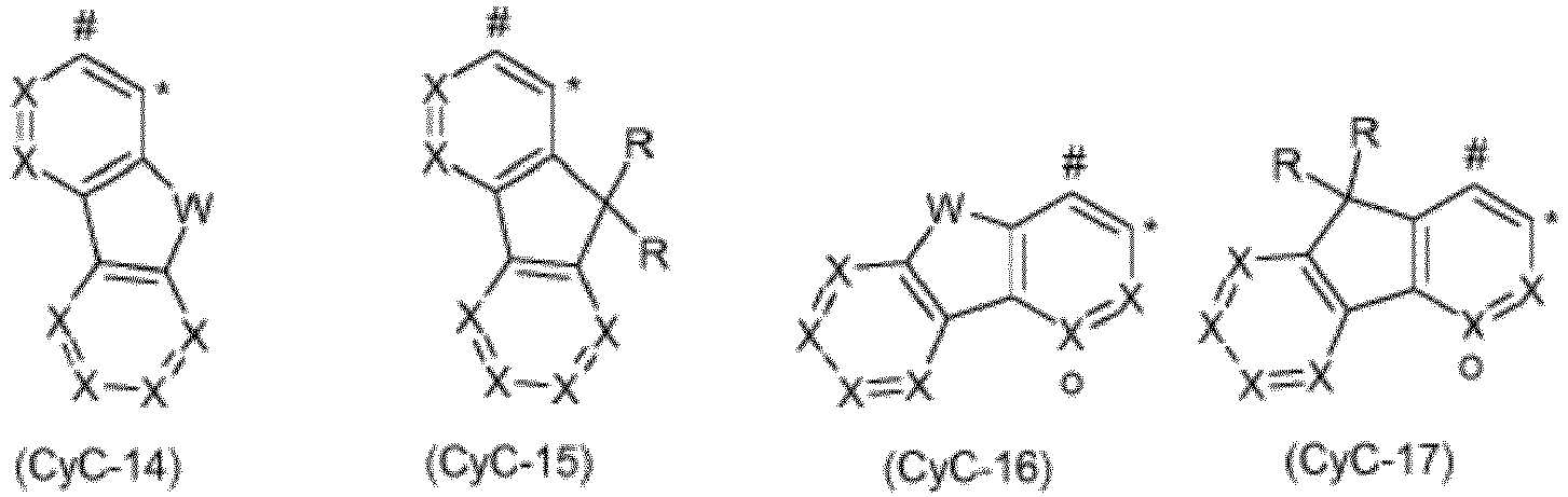


 X, identique ou différent en chaque occurrence, est CR ou N à la condition qu'au maximum deux symboles X par cycle représentent N ;W, identique ou différent en chaque occurrence, est NR, O ou S ;à la condition que lorsque le pont V est lié à CyC, un symbole X dans le groupe correspondant CyC représente C et le pont V est lié au niveau de cet atome de carbone, et lorsque le pont V est lié à CyD, un symbole X dans le groupe correspondant CyD représente C et le pont V est lié au niveau de cet atome de carbone ; la liaison au pont V est alors réalisée par l'intermédiaire d'une position qui est marquée par « o ».
 - Procédé pour la préparation d'un composé selon l'une ou plusieurs des revendications 1 à 10 par la transformation du ligand libre avec des alcoolates d'iridium de formule (52), avec des cétocétonates d'iridium de formule (53), avec des halogénures d'iridium de formule (54) ou avec des carboxylates d'iridium de formule (55),

- Formulation, contenant au moins un composé selon l'une ou plusieurs des revendications 1 à 10 et au moins un composé supplémentaire, le composé supplémentaire étant préférablement choisi parmi un matériau de matrice et/ou un solvant.
- Utilisation d'un composé selon l'une ou plusieurs des revendications 1 à 10 dans un dispositif électronique ou en tant que sensibilisateur à l'oxygène ou en tant que photoinitiateur ou en tant que photocatalyseur.
- Dispositif électronique contenant au moins un composé selon l'une ou plusieurs des revendications 1 à 10, le dispositif électronique étant préférablement choisi dans le groupe constitué par des dispositifs organiques d'électroluminescence, des circuits intégrés organiques, des transistors organiques à effet de champ, des transistors organiques en film mince, des transistors organiques luminescents, des cellules solaires organiques, des détecteurs optiques organiques, des photorécepteurs organiques, des dispositifs organiques d'extinction de champ, des cellules électrochimiques luminescentes, des capteurs infrarouges, des capteurs d'oxygène et des diodes laser organiques.
- Dispositif électronique selon la revendication 14, qui est un dispositif organique d'électroluminescence, caractérisé en ce que le composé selon l'une ou plusieurs des revendications 1 à 10 est utilisé dans une ou plusieurs couches émettrices.
Applications Claiming Priority (2)
| Application Number | Priority Date | Filing Date | Title |
|---|---|---|---|
| EP17182995 | 2017-07-25 | ||
| PCT/EP2018/069854 WO2019020538A1 (fr) | 2017-07-25 | 2018-07-23 | Complexes métalliques |
Publications (2)
| Publication Number | Publication Date |
|---|---|
| EP3658564A1 EP3658564A1 (fr) | 2020-06-03 |
| EP3658564B1 true EP3658564B1 (fr) | 2021-05-19 |
Family
ID=59399323
Family Applications (1)
| Application Number | Title | Priority Date | Filing Date |
|---|---|---|---|
| EP18740862.0A Active EP3658564B1 (fr) | 2017-07-25 | 2018-07-23 | Complexes métalliques |
Country Status (6)
| Country | Link |
|---|---|
| US (1) | US11535640B2 (fr) |
| EP (1) | EP3658564B1 (fr) |
| JP (1) | JP7175959B2 (fr) |
| CN (1) | CN110959010B (fr) |
| TW (1) | TWI776926B (fr) |
| WO (1) | WO2019020538A1 (fr) |
Cited By (1)
| Publication number | Priority date | Publication date | Assignee | Title |
|---|---|---|---|---|
| US11535640B2 (en) | 2017-07-25 | 2022-12-27 | Merck Patent Gmbh | Metal complexes |
Families Citing this family (65)
| Publication number | Priority date | Publication date | Assignee | Title |
|---|---|---|---|---|
| WO2020011686A1 (fr) | 2018-07-09 | 2020-01-16 | Merck Patent Gmbh | Matériaux pour dispositifs électroluminescents organiques |
| US20220020934A1 (en) | 2018-11-06 | 2022-01-20 | Merck Patent Gmbh | 5,6-diphenyl-5,6-dihydro-dibenz[c,e][1,2]azaphosphorin and 6-phenyl-6h-dibenzo[c,e][1,2]thiazin-5,5-dioxide derivatives and similar compounds as organic electroluminescent materials for oleds |
| TW202035345A (zh) | 2019-01-17 | 2020-10-01 | 德商麥克專利有限公司 | 用於有機電致發光裝置之材料 |
| EP3938367A1 (fr) | 2019-03-12 | 2022-01-19 | Merck Patent GmbH | Matériaux pour dispositifs électroluminescents organiques |
| EP3941920B1 (fr) | 2019-03-20 | 2024-03-20 | Merck Patent GmbH | Matériaux pour dispositifs électroluminescents organiques |
| US20220216424A1 (en) | 2019-03-25 | 2022-07-07 | Merck Patent Gmbh | Materials for organic electroluminescent devices |
| WO2021013775A1 (fr) | 2019-07-22 | 2021-01-28 | Merck Patent Gmbh | Procédé de production de composés métalliques ortho-metallés |
| CN114222738A (zh) | 2019-08-26 | 2022-03-22 | 默克专利有限公司 | 用于有机电致发光器件的材料 |
| US20220310932A1 (en) | 2019-09-02 | 2022-09-29 | Merck Patent Gmbh | Materials for organic electroluminescent devices |
| KR20220066324A (ko) | 2019-09-20 | 2022-05-24 | 메르크 파텐트 게엠베하 | 전자 디바이스용 재료 |
| EP4049325A1 (fr) | 2019-10-22 | 2022-08-31 | Merck Patent GmbH | Matériaux pour dispositifs électroluminescents organiques |
| WO2021078831A1 (fr) | 2019-10-25 | 2021-04-29 | Merck Patent Gmbh | Composés pouvant être utilisés dans un dispositif électronique organique |
| TW202136471A (zh) | 2019-12-17 | 2021-10-01 | 德商麥克專利有限公司 | 有機電致發光裝置用的材料 |
| WO2021122538A1 (fr) | 2019-12-18 | 2021-06-24 | Merck Patent Gmbh | Composés aromatiques pour dispositifs électroluminescents organiques |
| JP2023506570A (ja) | 2019-12-19 | 2023-02-16 | メルク パテント ゲゼルシャフト ミット ベシュレンクテル ハフツング | 有機エレクトロルミネッセンス素子のための多環式化合物 |
| EP4110884A1 (fr) | 2020-02-25 | 2023-01-04 | Merck Patent GmbH | Utilisation de composés hétérocycliques dans un dispositif électronique organique |
| WO2021175706A1 (fr) | 2020-03-02 | 2021-09-10 | Merck Patent Gmbh | Utilisation de composés sulfone dans un dispositif électronique organique |
| US20230147279A1 (en) | 2020-03-17 | 2023-05-11 | Merck Patent Gmbh | Heterocyclic compounds for organic electroluminescent devices |
| CN115298187A (zh) | 2020-03-17 | 2022-11-04 | 默克专利有限公司 | 用于有机电致发光器件的杂芳族化合物 |
| EP4126868A1 (fr) | 2020-03-24 | 2023-02-08 | Merck Patent GmbH | Matériaux pour dispositifs électroniques |
| KR20220158771A (ko) | 2020-03-26 | 2022-12-01 | 메르크 파텐트 게엠베하 | 유기 전계 발광 디바이스용 환형 화합물 |
| EP4126870A1 (fr) | 2020-04-02 | 2023-02-08 | Merck Patent GmbH | Matériaux pour dispositifs électroluminescents organiques |
| JP2023520710A (ja) | 2020-04-06 | 2023-05-18 | メルク パテント ゲゼルシャフト ミット ベシュレンクテル ハフツング | 有機エレクトロルミネッセンス素子のための多環式化合物 |
| KR20230017816A (ko) | 2020-05-29 | 2023-02-06 | 메르크 파텐트 게엠베하 | 유기 전계 발광 장치 |
| CN115867426A (zh) | 2020-06-23 | 2023-03-28 | 默克专利有限公司 | 生产混合物的方法 |
| CN115916795A (zh) | 2020-06-29 | 2023-04-04 | 默克专利有限公司 | 用于有机电致发光器件的杂芳族化合物 |
| WO2022002771A1 (fr) | 2020-06-29 | 2022-01-06 | Merck Patent Gmbh | Composés hétérocycliques pour dispositifs électroluminescents organiques |
| CN116157402A (zh) | 2020-08-06 | 2023-05-23 | 默克专利有限公司 | 用于有机电致发光器件的材料 |
| WO2022034046A1 (fr) | 2020-08-13 | 2022-02-17 | Merck Patent Gmbh | Complexes métalliques |
| CN115956074A (zh) | 2020-08-18 | 2023-04-11 | 默克专利有限公司 | 用于有机电致发光器件的材料 |
| TW202223066A (zh) | 2020-08-19 | 2022-06-16 | 德商麥克專利有限公司 | 用於有機電致發光裝置之材料 |
| TW202229215A (zh) | 2020-09-30 | 2022-08-01 | 德商麥克專利有限公司 | 用於有機電致發光裝置功能層之結構化的化合物 |
| TW202222748A (zh) | 2020-09-30 | 2022-06-16 | 德商麥克專利有限公司 | 用於結構化有機電致發光裝置的功能層之化合物 |
| KR20230088748A (ko) | 2020-10-16 | 2023-06-20 | 메르크 파텐트 게엠베하 | 유기 전계 발광 디바이스용 헤테로원자를 포함하는 화합물 |
| EP4229064A1 (fr) | 2020-10-16 | 2023-08-23 | Merck Patent GmbH | Composés hétérocycliques pour dispositifs électroluminescents organiques |
| WO2022122682A2 (fr) | 2020-12-10 | 2022-06-16 | Merck Patent Gmbh | Matériaux pour dispositifs électroluminescents organiques |
| US20240101560A1 (en) | 2020-12-18 | 2024-03-28 | Merck Patent Gmbh | Nitrogenous heteroaromatic compounds for organic electroluminescent devices |
| EP4263543A1 (fr) | 2020-12-18 | 2023-10-25 | Merck Patent GmbH | Composés azotés pour dispositifs électroluminescents organiques |
| KR20230122094A (ko) | 2020-12-18 | 2023-08-22 | 메르크 파텐트 게엠베하 | Oled에 사용하기 위한 청색 형광 방출체로서의 인돌로[3.2.1-jk]카르바졸-6-카르보니트릴유도체 |
| US20240083891A1 (en) | 2021-01-05 | 2024-03-14 | Merck Patent Gmbh | Materials for organic electroluminescent devices |
| KR20240005806A (ko) | 2021-04-29 | 2024-01-12 | 메르크 파텐트 게엠베하 | 유기 전계발광 디바이스용 재료 |
| CN117203191A (zh) | 2021-04-29 | 2023-12-08 | 默克专利有限公司 | 用于有机电致发光器件的材料 |
| CN117425655A (zh) | 2021-04-30 | 2024-01-19 | 默克专利有限公司 | 用于有机电致发光器件的含氮杂环化合物 |
| CN117355364A (zh) | 2021-05-21 | 2024-01-05 | 默克专利有限公司 | 用于连续纯化至少一种功能材料的方法和用于连续纯化至少一种功能材料的装置 |
| WO2022200638A1 (fr) | 2021-07-06 | 2022-09-29 | Merck Patent Gmbh | Matériaux pour dispositifs électroluminescents organiques |
| WO2023036976A1 (fr) | 2021-09-13 | 2023-03-16 | Merck Patent Gmbh | Matériaux pour dispositifs électroluminescents organiques |
| WO2023041454A1 (fr) | 2021-09-14 | 2023-03-23 | Merck Patent Gmbh | Composés hétérocycliques contenant du bore pour dispositifs électroluminescents organiques |
| WO2023052275A1 (fr) | 2021-09-28 | 2023-04-06 | Merck Patent Gmbh | Matériaux pour dispositifs électroniques |
| WO2023052272A1 (fr) | 2021-09-28 | 2023-04-06 | Merck Patent Gmbh | Matériaux pour dispositifs électroniques |
| WO2023052313A1 (fr) | 2021-09-28 | 2023-04-06 | Merck Patent Gmbh | Matériaux pour dispositifs électroniques |
| WO2023052314A1 (fr) | 2021-09-28 | 2023-04-06 | Merck Patent Gmbh | Matériaux pour dispositifs électroniques |
| WO2023072799A1 (fr) | 2021-10-27 | 2023-05-04 | Merck Patent Gmbh | Composés hétérocycliques contenant du bore et de l'azote pour dispositifs électroluminescents organiques |
| WO2023094412A1 (fr) | 2021-11-25 | 2023-06-01 | Merck Patent Gmbh | Matériaux pour dispositifs électroniques |
| WO2023110742A1 (fr) | 2021-12-13 | 2023-06-22 | Merck Patent Gmbh | Matériaux pour dispositifs électroluminescents organiques |
| CN114262292A (zh) * | 2021-12-20 | 2022-04-01 | 上海工程技术大学 | 吡啶类衍生物及其制备方法和用途 |
| WO2023117837A1 (fr) | 2021-12-21 | 2023-06-29 | Merck Patent Gmbh | Procédé de préparation de composés organiques deutériés |
| WO2023152063A1 (fr) | 2022-02-09 | 2023-08-17 | Merck Patent Gmbh | Matériaux pour dispositifs électroluminescents organiques |
| WO2023152346A1 (fr) | 2022-02-14 | 2023-08-17 | Merck Patent Gmbh | Matériaux pour dispositifs électroniques |
| WO2023161167A1 (fr) | 2022-02-23 | 2023-08-31 | Merck Patent Gmbh | Hétérocycles azotés pour dispositifs électroluminescents organiques |
| WO2023161168A1 (fr) | 2022-02-23 | 2023-08-31 | Merck Patent Gmbh | Hétérocycles aromatiques pour dispositifs électroluminescents organiques |
| WO2023222559A1 (fr) | 2022-05-18 | 2023-11-23 | Merck Patent Gmbh | Procédé de préparation de composés organiques deutérés |
| WO2023247662A1 (fr) | 2022-06-24 | 2023-12-28 | Merck Patent Gmbh | Composition pour dispositifs électroniques organiques |
| WO2023247663A1 (fr) | 2022-06-24 | 2023-12-28 | Merck Patent Gmbh | Composition pour dispositifs électroniques organiques |
| WO2024013004A1 (fr) | 2022-07-11 | 2024-01-18 | Merck Patent Gmbh | Matériaux pour dispositifs électroniques |
| WO2024033282A1 (fr) | 2022-08-09 | 2024-02-15 | Merck Patent Gmbh | Matériaux pour dispositifs électroluminescents organiques |
Family Cites Families (83)
| Publication number | Priority date | Publication date | Assignee | Title |
|---|---|---|---|---|
| US5061569A (en) | 1990-07-26 | 1991-10-29 | Eastman Kodak Company | Electroluminescent device with organic electroluminescent medium |
| DE69432054T2 (de) | 1993-09-29 | 2003-10-09 | Idemitsu Kosan Co | Organische elektrolumineszenzelemente und arylendiaminderivate |
| JPH07133483A (ja) | 1993-11-09 | 1995-05-23 | Shinko Electric Ind Co Ltd | El素子用有機発光材料及びel素子 |
| KR100377321B1 (ko) | 1999-12-31 | 2003-03-26 | 주식회사 엘지화학 | 피-형 반도체 성질을 갖는 유기 화합물을 포함하는 전기소자 |
| TW532048B (en) | 2000-03-27 | 2003-05-11 | Idemitsu Kosan Co | Organic electroluminescence element |
| DE10058578C2 (de) | 2000-11-20 | 2002-11-28 | Univ Dresden Tech | Lichtemittierendes Bauelement mit organischen Schichten |
| WO2002051850A1 (fr) | 2000-12-22 | 2002-07-04 | Covion Organic Semiconductors Gmbh | Composes spiro a base de bore et d'aluminium et leur utilisation dans l'industrie electronique |
| DE10104426A1 (de) | 2001-02-01 | 2002-08-08 | Covion Organic Semiconductors | Verfahren zur Herstellung von hochreinen, tris-ortho-metallierten Organo-Iridium-Verbindungen |
| US6597012B2 (en) | 2001-05-02 | 2003-07-22 | Junji Kido | Organic electroluminescent device |
| ITRM20020411A1 (it) | 2002-08-01 | 2004-02-02 | Univ Roma La Sapienza | Derivati dello spirobifluorene, loro preparazione e loro uso. |
| DE10249723A1 (de) | 2002-10-25 | 2004-05-06 | Covion Organic Semiconductors Gmbh | Arylamin-Einheiten enthaltende konjugierte Polymere, deren Darstellung und Verwendung |
| WO2004058911A2 (fr) | 2002-12-23 | 2004-07-15 | Covion Organic Semiconductors Gmbh | Element electroluminescent organique |
| JP4411851B2 (ja) | 2003-03-19 | 2010-02-10 | コニカミノルタホールディングス株式会社 | 有機エレクトロルミネッセンス素子 |
| DE10314102A1 (de) | 2003-03-27 | 2004-10-14 | Covion Organic Semiconductors Gmbh | Verfahren zur Herstellung von hochreinen Organo-Iridium-Verbindungen |
| EP2281861A3 (fr) | 2003-04-15 | 2012-03-28 | Merck Patent GmbH | Mélanges de semi-conducteurs organiques destinés à l'émission et matériaux de matrice, leur utilisation et composants électroniques pourvus de ces mélanges |
| EP2236579B1 (fr) | 2003-04-23 | 2014-04-09 | Konica Minolta Holdings, Inc. | Dispositif organique éléctroluminescent et dispositif d'affichage |
| DE10333232A1 (de) | 2003-07-21 | 2007-10-11 | Merck Patent Gmbh | Organisches Elektrolumineszenzelement |
| US7795801B2 (en) | 2003-09-30 | 2010-09-14 | Konica Minolta Holdings, Inc. | Organic electroluminescent element, illuminator, display and compound |
| US7790890B2 (en) | 2004-03-31 | 2010-09-07 | Konica Minolta Holdings, Inc. | Organic electroluminescence element material, organic electroluminescence element, display device and illumination device |
| KR100787425B1 (ko) | 2004-11-29 | 2007-12-26 | 삼성에스디아이 주식회사 | 페닐카바졸계 화합물 및 이를 이용한 유기 전계 발광 소자 |
| DE102004023277A1 (de) | 2004-05-11 | 2005-12-01 | Covion Organic Semiconductors Gmbh | Neue Materialmischungen für die Elektrolumineszenz |
| JP4862248B2 (ja) | 2004-06-04 | 2012-01-25 | コニカミノルタホールディングス株式会社 | 有機エレクトロルミネッセンス素子、照明装置及び表示装置 |
| ITRM20040352A1 (it) | 2004-07-15 | 2004-10-15 | Univ Roma La Sapienza | Derivati oligomerici dello spirobifluorene, loro preparazione e loro uso. |
| KR101249172B1 (ko) | 2004-07-30 | 2013-03-29 | 산요덴키가부시키가이샤 | 유기 일렉트로루미네센스 소자 |
| JP2006135145A (ja) | 2004-11-08 | 2006-05-25 | Sony Corp | 表示素子用有機材料および表示素子 |
| JP4747558B2 (ja) | 2004-11-08 | 2011-08-17 | ソニー株式会社 | 表示素子用有機材料および表示素子 |
| US20090066225A1 (en) | 2005-03-18 | 2009-03-12 | Idemitsu Kosan Co., Ltd. | Aromatic amine derivative and organic electroluminescence device utilizing the same |
| JP5242380B2 (ja) | 2005-05-03 | 2013-07-24 | メルク パテント ゲーエムベーハー | 有機エレクトロルミネッセンス素子 |
| DE102005023437A1 (de) | 2005-05-20 | 2006-11-30 | Merck Patent Gmbh | Verbindungen für organische elektronische Vorrichtungen |
| JP4593631B2 (ja) | 2005-12-01 | 2010-12-08 | 新日鐵化学株式会社 | 有機電界発光素子用化合物及び有機電界発光素子 |
| DE102006025777A1 (de) | 2006-05-31 | 2007-12-06 | Merck Patent Gmbh | Neue Materialien für organische Elektrolumineszenzvorrichtungen |
| DE102006025846A1 (de) | 2006-06-02 | 2007-12-06 | Merck Patent Gmbh | Neue Materialien für organische Elektrolumineszenzvorrichtungen |
| DE102006031990A1 (de) | 2006-07-11 | 2008-01-17 | Merck Patent Gmbh | Neue Materialien für organische Elektrolumineszenzvorrichtungen |
| WO2008056746A1 (fr) | 2006-11-09 | 2008-05-15 | Nippon Steel Chemical Co., Ltd. | Composé pour un dispositif électroluminescent organique et dispositif électroluminescent organique |
| DE102007002714A1 (de) | 2007-01-18 | 2008-07-31 | Merck Patent Gmbh | Neue Materialien für organische Elektrolumineszenzvorrichtungen |
| DE102007053771A1 (de) | 2007-11-12 | 2009-05-14 | Merck Patent Gmbh | Organische Elektrolumineszenzvorrichtungen |
| US7862908B2 (en) | 2007-11-26 | 2011-01-04 | National Tsing Hua University | Conjugated compounds containing hydroindoloacridine structural elements, and their use |
| US8221905B2 (en) | 2007-12-28 | 2012-07-17 | Universal Display Corporation | Carbazole-containing materials in phosphorescent light emitting diodes |
| JP5357150B2 (ja) | 2008-06-05 | 2013-12-04 | 出光興産株式会社 | ハロゲン化合物、多環系化合物及びそれを用いた有機エレクトロルミネッセンス素子 |
| DE102008033943A1 (de) | 2008-07-18 | 2010-01-21 | Merck Patent Gmbh | Neue Materialien für organische Elektrolumineszenzvorrichtungen |
| DE102008036247A1 (de) * | 2008-08-04 | 2010-02-11 | Merck Patent Gmbh | Elektronische Vorrichtungen enthaltend Metallkomplexe |
| DE102008036982A1 (de) | 2008-08-08 | 2010-02-11 | Merck Patent Gmbh | Organische Elektrolumineszenzvorrichtung |
| KR101506919B1 (ko) | 2008-10-31 | 2015-03-30 | 롬엔드하스전자재료코리아유한회사 | 신규한 유기 전자재료용 화합물 및 이를 포함하는 유기 전자 소자 |
| CN102076813B (zh) | 2008-11-11 | 2016-05-18 | 默克专利有限公司 | 有机电致发光器件 |
| DE102008056688A1 (de) | 2008-11-11 | 2010-05-12 | Merck Patent Gmbh | Materialien für organische Elektrolumineszenzvorrichtungen |
| DE102009014513A1 (de) | 2009-03-23 | 2010-09-30 | Merck Patent Gmbh | Organische Elektrolumineszenzvorrichtung |
| DE102009023155A1 (de) | 2009-05-29 | 2010-12-02 | Merck Patent Gmbh | Materialien für organische Elektrolumineszenzvorrichtungen |
| DE102009031021A1 (de) | 2009-06-30 | 2011-01-05 | Merck Patent Gmbh | Materialien für organische Elektrolumineszenzvorrichtungen |
| DE102009048791A1 (de) | 2009-10-08 | 2011-04-14 | Merck Patent Gmbh | Materialien für organische Elektrolumineszenzvorrichtungen |
| DE102010005697A1 (de) | 2010-01-25 | 2011-07-28 | Merck Patent GmbH, 64293 | Verbindungen für elektronische Vorrichtungen |
| WO2012008550A1 (fr) | 2010-07-16 | 2012-01-19 | 住友化学株式会社 | Composé polymère, composition contenant le composé polymère, composition liquide, élément et film minces, et source lumineuse de surface et dispositif d'affichage utilisant l'élément |
| DE102010045405A1 (de) | 2010-09-15 | 2012-03-15 | Merck Patent Gmbh | Materialien für organische Elektrolumineszenzvorrichtungen |
| DE102010048498A1 (de) | 2010-10-14 | 2012-04-19 | Merck Patent Gmbh | Materialien für organische Elektrolumineszenzvorrichtungen |
| JP5677036B2 (ja) * | 2010-11-08 | 2015-02-25 | キヤノン株式会社 | 有機発光素子 |
| JP6022478B2 (ja) | 2011-01-13 | 2016-11-09 | メルク パテント ゲーエムベーハー | 有機エレクトロルミネッセンス素子のための材料 |
| CN103503187B (zh) | 2011-05-05 | 2016-11-02 | 默克专利有限公司 | 用于电子器件的化合物 |
| KR102115018B1 (ko) | 2011-11-17 | 2020-05-26 | 메르크 파텐트 게엠베하 | 스피로디히드로아크리딘 유도체 및 이의 유기 전계발광 소자용 재료로서의 용도 |
| JP5920013B2 (ja) | 2012-05-21 | 2016-05-18 | コニカミノルタ株式会社 | 有機エレクトロルミネッセンス素子、有機エレクトロルミネッセンス素子の製造方法、表示装置および照明装置 |
| CN108054293B (zh) | 2012-07-23 | 2020-05-22 | 默克专利有限公司 | 2-二芳基氨基芴的衍生物和含有所述2-二芳基氨基芴衍生物的有机电子复合体 |
| JP6219388B2 (ja) | 2012-07-23 | 2017-10-25 | メルク パテント ゲーエムベーハー | フルオレンおよびそれらを含む有機電子素子 |
| CN110444694B (zh) | 2012-07-23 | 2023-04-07 | 默克专利有限公司 | 化合物以及有机电致发光器件 |
| EP2907173B1 (fr) | 2012-10-09 | 2018-03-21 | Merck Patent GmbH | Dispositif électronique |
| KR102179608B1 (ko) | 2012-12-18 | 2020-11-17 | 메르크 파텐트 게엠베하 | 유기 전계발광 소자 |
| DE102013215342B4 (de) | 2013-08-05 | 2023-05-04 | Novaled Gmbh | Verfahren zur Herstellung organisch phosphoreszenter Schichten unter Zusatz schwerer Hauptgruppenmetallkomplexe, damit hergestellte Schicht, deren Verwendung und organisches Halbleiterbauelement diese umfassend |
| EP3052505B1 (fr) | 2013-10-02 | 2021-06-23 | Merck Patent GmbH | Composés contenant du bore |
| CN106459018B (zh) | 2014-05-05 | 2022-01-25 | 默克专利有限公司 | 用于有机发光器件的材料 |
| US11024815B2 (en) * | 2015-02-03 | 2021-06-01 | Merck Patent Gmbh | Metal complexes |
| CN107635987B (zh) | 2015-05-18 | 2023-01-03 | 默克专利有限公司 | 用于有机电致发光器件的材料 |
| CN107922451B (zh) | 2015-08-25 | 2023-01-31 | 默克专利有限公司 | 金属络合物 |
| US11713332B2 (en) | 2016-07-14 | 2023-08-01 | Merck Patent Gmbh | Metal complexes |
| JP7030780B2 (ja) | 2016-07-25 | 2022-03-07 | メルク パテント ゲゼルシャフト ミット ベシュレンクテル ハフツング | 三脚型二座副配位子を含む、二核およびオリゴ核の金属錯体、並びにその電子デバイスにおける使用 |
| KR101836041B1 (ko) | 2016-08-30 | 2018-03-07 | 메르크 파텐트 게엠베하 | 금속 착물 |
| KR102464513B1 (ko) | 2016-09-21 | 2022-11-07 | 메르크 파텐트 게엠베하 | 유기 전계발광 소자에서 이미터로서 사용하기 위한 2핵 금속 착물 |
| JP7064487B2 (ja) | 2016-10-12 | 2022-05-10 | メルク パテント ゲゼルシャフト ミット ベシュレンクテル ハフツング | 金属錯体 |
| WO2018069196A1 (fr) | 2016-10-12 | 2018-04-19 | Merck Patent Gmbh | Complexes métalliques binucléaires, ainsi que dispositifs électroniques, en particulier dispositifs électroluminescents organiques, contenant lesdits complexes métalliques |
| JP7023946B2 (ja) | 2016-10-13 | 2022-02-22 | メルク パテント ゲゼルシャフト ミット ベシュレンクテル ハフツング | 金属錯体 |
| US20190280220A1 (en) | 2016-10-25 | 2019-09-12 | Merck Patent Gmbh | Metal complexes |
| CN110461859A (zh) * | 2017-03-29 | 2019-11-15 | 默克专利有限公司 | 金属络合物 |
| EP3601257B1 (fr) | 2017-03-29 | 2021-10-27 | Merck Patent GmbH | Composés aromatiques |
| TWI776926B (zh) | 2017-07-25 | 2022-09-11 | 德商麥克專利有限公司 | 金屬錯合物 |
| EP3724202B1 (fr) * | 2017-12-13 | 2022-08-17 | Merck Patent GmbH | Complexes métalliques |
| TWI820084B (zh) | 2018-02-13 | 2023-11-01 | 愛爾蘭商Udc愛爾蘭責任有限公司 | 金屬錯合物、彼之製備方法、彼之用途、及包含彼之電子裝置 |
| TWI828664B (zh) | 2018-03-19 | 2024-01-11 | 愛爾蘭商Udc愛爾蘭責任有限公司 | 金屬錯合物 |
-
2018
- 2018-07-20 TW TW107125089A patent/TWI776926B/zh active
- 2018-07-23 CN CN201880047777.XA patent/CN110959010B/zh active Active
- 2018-07-23 WO PCT/EP2018/069854 patent/WO2019020538A1/fr unknown
- 2018-07-23 US US16/634,012 patent/US11535640B2/en active Active
- 2018-07-23 EP EP18740862.0A patent/EP3658564B1/fr active Active
- 2018-07-23 JP JP2020503855A patent/JP7175959B2/ja active Active
Cited By (1)
| Publication number | Priority date | Publication date | Assignee | Title |
|---|---|---|---|---|
| US11535640B2 (en) | 2017-07-25 | 2022-12-27 | Merck Patent Gmbh | Metal complexes |
Also Published As
| Publication number | Publication date |
|---|---|
| JP7175959B2 (ja) | 2022-11-21 |
| TWI776926B (zh) | 2022-09-11 |
| WO2019020538A1 (fr) | 2019-01-31 |
| EP3658564A1 (fr) | 2020-06-03 |
| US20200207794A1 (en) | 2020-07-02 |
| CN110959010B (zh) | 2024-01-23 |
| KR20200031148A (ko) | 2020-03-23 |
| JP2020529979A (ja) | 2020-10-15 |
| CN110959010A (zh) | 2020-04-03 |
| US11535640B2 (en) | 2022-12-27 |
| TW201920224A (zh) | 2019-06-01 |
Similar Documents
| Publication | Publication Date | Title |
|---|---|---|
| EP3658564B1 (fr) | Complexes métalliques | |
| EP3768692B1 (fr) | Complexes métalliques | |
| EP3724202B1 (fr) | Complexes métalliques | |
| EP3487864B1 (fr) | Complexes métalliques trouvant application comme émetteurs dans des dispositifs électroluminescents organiques | |
| EP3487865B1 (fr) | Complexes métalliques dinucléaires et oligonucléaires comprenant des sous-unités de ligands tripodes bidentées ainsi que leur utilisation dans des dispositifs électroniques | |
| EP3601304B1 (fr) | Complexes métalliques | |
| EP3526228B1 (fr) | Complexes métalliques | |
| EP3526226B1 (fr) | Complexes métalliques | |
| EP3424936B1 (fr) | Complexe métallique | |
| EP2935293B1 (fr) | Complexes du iridium et leur utilisation dans les dispositifs electroniques en particulier les dispositifs electroluminescentes | |
| WO2019158453A1 (fr) | Complexes métalliques | |
| EP2714704B1 (fr) | Complexes métalliques | |
| EP3515925A1 (fr) | Complexes métalliques trouvant application comme émetteurs dans des dispositifs électroluminescents organiques | |
| WO2018011186A1 (fr) | Complexes métalliques | |
| WO2018069196A1 (fr) | Complexes métalliques binucléaires, ainsi que dispositifs électroniques, en particulier dispositifs électroluminescents organiques, contenant lesdits complexes métalliques | |
| WO2018041769A1 (fr) | Complexes métalliques binucléaires et trinucléaires obtenus à partir de deux ligands hexadentés tripodaux liés entre eux, destinés à être utilisés dans des dispositifs électroluminescents | |
| EP3341385A1 (fr) | Complexes métalliques | |
| EP3016952B1 (fr) | Composés de lactame spirocondensés pour des dispositifs électroluminescents organiques | |
| EP3160976A1 (fr) | Complexes métalliques | |
| EP3708634A1 (fr) | Composés spiraniques hétérocycliques | |
| EP3507294A1 (fr) | Complexes métalliques binucléaires et trinucléaires obtenus à partir de deux ligands hexadentés tripodaux liés entre eux, destinés à être utilisés dans des dispositifs électroluminescents | |
| EP3532480B1 (fr) | Complexes métalliques | |
| WO2018050583A1 (fr) | Composés à structures carbazole | |
| EP4031549A1 (fr) | Composés hétérocycliques péri-condensés en tant que matériaux destinés à des dispositifs électroniques |
Legal Events
| Date | Code | Title | Description |
|---|---|---|---|
| STAA | Information on the status of an ep patent application or granted ep patent |
Free format text: STATUS: UNKNOWN |
|
| STAA | Information on the status of an ep patent application or granted ep patent |
Free format text: STATUS: THE INTERNATIONAL PUBLICATION HAS BEEN MADE |
|
| PUAI | Public reference made under article 153(3) epc to a published international application that has entered the european phase |
Free format text: ORIGINAL CODE: 0009012 |
|
| STAA | Information on the status of an ep patent application or granted ep patent |
Free format text: STATUS: REQUEST FOR EXAMINATION WAS MADE |
|
| 17P | Request for examination filed |
Effective date: 20200122 |
|
| AK | Designated contracting states |
Kind code of ref document: A1 Designated state(s): AL AT BE BG CH CY CZ DE DK EE ES FI FR GB GR HR HU IE IS IT LI LT LU LV MC MK MT NL NO PL PT RO RS SE SI SK SM TR |
|
| AX | Request for extension of the european patent |
Extension state: BA ME |
|
| DAV | Request for validation of the european patent (deleted) | ||
| DAX | Request for extension of the european patent (deleted) | ||
| GRAP | Despatch of communication of intention to grant a patent |
Free format text: ORIGINAL CODE: EPIDOSNIGR1 |
|
| STAA | Information on the status of an ep patent application or granted ep patent |
Free format text: STATUS: GRANT OF PATENT IS INTENDED |
|
| INTG | Intention to grant announced |
Effective date: 20210122 |
|
| GRAS | Grant fee paid |
Free format text: ORIGINAL CODE: EPIDOSNIGR3 |
|
| GRAA | (expected) grant |
Free format text: ORIGINAL CODE: 0009210 |
|
| STAA | Information on the status of an ep patent application or granted ep patent |
Free format text: STATUS: THE PATENT HAS BEEN GRANTED |
|
| AK | Designated contracting states |
Kind code of ref document: B1 Designated state(s): AL AT BE BG CH CY CZ DE DK EE ES FI FR GB GR HR HU IE IS IT LI LT LU LV MC MK MT NL NO PL PT RO RS SE SI SK SM TR |
|
| REG | Reference to a national code |
Ref country code: GB Ref legal event code: FG4D Free format text: NOT ENGLISH |
|
| REG | Reference to a national code |
Ref country code: CH Ref legal event code: EP |
|
| REG | Reference to a national code |
Ref country code: DE Ref legal event code: R096 Ref document number: 502018005347 Country of ref document: DE |
|
| REG | Reference to a national code |
Ref country code: AT Ref legal event code: REF Ref document number: 1393870 Country of ref document: AT Kind code of ref document: T Effective date: 20210615 |
|
| REG | Reference to a national code |
Ref country code: IE Ref legal event code: FG4D Free format text: LANGUAGE OF EP DOCUMENT: GERMAN |
|
| REG | Reference to a national code |
Ref country code: LT Ref legal event code: MG9D |
|
| REG | Reference to a national code |
Ref country code: NL Ref legal event code: MP Effective date: 20210519 |
|
| PG25 | Lapsed in a contracting state [announced via postgrant information from national office to epo] |
Ref country code: LT Free format text: LAPSE BECAUSE OF FAILURE TO SUBMIT A TRANSLATION OF THE DESCRIPTION OR TO PAY THE FEE WITHIN THE PRESCRIBED TIME-LIMIT Effective date: 20210519 Ref country code: HR Free format text: LAPSE BECAUSE OF FAILURE TO SUBMIT A TRANSLATION OF THE DESCRIPTION OR TO PAY THE FEE WITHIN THE PRESCRIBED TIME-LIMIT Effective date: 20210519 Ref country code: FI Free format text: LAPSE BECAUSE OF FAILURE TO SUBMIT A TRANSLATION OF THE DESCRIPTION OR TO PAY THE FEE WITHIN THE PRESCRIBED TIME-LIMIT Effective date: 20210519 Ref country code: BG Free format text: LAPSE BECAUSE OF FAILURE TO SUBMIT A TRANSLATION OF THE DESCRIPTION OR TO PAY THE FEE WITHIN THE PRESCRIBED TIME-LIMIT Effective date: 20210819 |
|
| PG25 | Lapsed in a contracting state [announced via postgrant information from national office to epo] |
Ref country code: LV Free format text: LAPSE BECAUSE OF FAILURE TO SUBMIT A TRANSLATION OF THE DESCRIPTION OR TO PAY THE FEE WITHIN THE PRESCRIBED TIME-LIMIT Effective date: 20210519 Ref country code: NO Free format text: LAPSE BECAUSE OF FAILURE TO SUBMIT A TRANSLATION OF THE DESCRIPTION OR TO PAY THE FEE WITHIN THE PRESCRIBED TIME-LIMIT Effective date: 20210819 Ref country code: PL Free format text: LAPSE BECAUSE OF FAILURE TO SUBMIT A TRANSLATION OF THE DESCRIPTION OR TO PAY THE FEE WITHIN THE PRESCRIBED TIME-LIMIT Effective date: 20210519 Ref country code: PT Free format text: LAPSE BECAUSE OF FAILURE TO SUBMIT A TRANSLATION OF THE DESCRIPTION OR TO PAY THE FEE WITHIN THE PRESCRIBED TIME-LIMIT Effective date: 20210920 Ref country code: RS Free format text: LAPSE BECAUSE OF FAILURE TO SUBMIT A TRANSLATION OF THE DESCRIPTION OR TO PAY THE FEE WITHIN THE PRESCRIBED TIME-LIMIT Effective date: 20210519 Ref country code: SE Free format text: LAPSE BECAUSE OF FAILURE TO SUBMIT A TRANSLATION OF THE DESCRIPTION OR TO PAY THE FEE WITHIN THE PRESCRIBED TIME-LIMIT Effective date: 20210519 Ref country code: GR Free format text: LAPSE BECAUSE OF FAILURE TO SUBMIT A TRANSLATION OF THE DESCRIPTION OR TO PAY THE FEE WITHIN THE PRESCRIBED TIME-LIMIT Effective date: 20210820 Ref country code: IS Free format text: LAPSE BECAUSE OF FAILURE TO SUBMIT A TRANSLATION OF THE DESCRIPTION OR TO PAY THE FEE WITHIN THE PRESCRIBED TIME-LIMIT Effective date: 20210919 |
|
| PG25 | Lapsed in a contracting state [announced via postgrant information from national office to epo] |
Ref country code: NL Free format text: LAPSE BECAUSE OF FAILURE TO SUBMIT A TRANSLATION OF THE DESCRIPTION OR TO PAY THE FEE WITHIN THE PRESCRIBED TIME-LIMIT Effective date: 20210519 |
|
| PG25 | Lapsed in a contracting state [announced via postgrant information from national office to epo] |
Ref country code: EE Free format text: LAPSE BECAUSE OF FAILURE TO SUBMIT A TRANSLATION OF THE DESCRIPTION OR TO PAY THE FEE WITHIN THE PRESCRIBED TIME-LIMIT Effective date: 20210519 Ref country code: ES Free format text: LAPSE BECAUSE OF FAILURE TO SUBMIT A TRANSLATION OF THE DESCRIPTION OR TO PAY THE FEE WITHIN THE PRESCRIBED TIME-LIMIT Effective date: 20210519 Ref country code: SK Free format text: LAPSE BECAUSE OF FAILURE TO SUBMIT A TRANSLATION OF THE DESCRIPTION OR TO PAY THE FEE WITHIN THE PRESCRIBED TIME-LIMIT Effective date: 20210519 Ref country code: DK Free format text: LAPSE BECAUSE OF FAILURE TO SUBMIT A TRANSLATION OF THE DESCRIPTION OR TO PAY THE FEE WITHIN THE PRESCRIBED TIME-LIMIT Effective date: 20210519 Ref country code: CZ Free format text: LAPSE BECAUSE OF FAILURE TO SUBMIT A TRANSLATION OF THE DESCRIPTION OR TO PAY THE FEE WITHIN THE PRESCRIBED TIME-LIMIT Effective date: 20210519 Ref country code: SM Free format text: LAPSE BECAUSE OF FAILURE TO SUBMIT A TRANSLATION OF THE DESCRIPTION OR TO PAY THE FEE WITHIN THE PRESCRIBED TIME-LIMIT Effective date: 20210519 Ref country code: RO Free format text: LAPSE BECAUSE OF FAILURE TO SUBMIT A TRANSLATION OF THE DESCRIPTION OR TO PAY THE FEE WITHIN THE PRESCRIBED TIME-LIMIT Effective date: 20210519 |
|
| REG | Reference to a national code |
Ref country code: DE Ref legal event code: R097 Ref document number: 502018005347 Country of ref document: DE |
|
| REG | Reference to a national code |
Ref country code: CH Ref legal event code: PL |
|
| PLBE | No opposition filed within time limit |
Free format text: ORIGINAL CODE: 0009261 |
|
| STAA | Information on the status of an ep patent application or granted ep patent |
Free format text: STATUS: NO OPPOSITION FILED WITHIN TIME LIMIT |
|
| PG25 | Lapsed in a contracting state [announced via postgrant information from national office to epo] |
Ref country code: MC Free format text: LAPSE BECAUSE OF FAILURE TO SUBMIT A TRANSLATION OF THE DESCRIPTION OR TO PAY THE FEE WITHIN THE PRESCRIBED TIME-LIMIT Effective date: 20210519 |
|
| REG | Reference to a national code |
Ref country code: BE Ref legal event code: MM Effective date: 20210731 |
|
| 26N | No opposition filed |
Effective date: 20220222 |
|
| PG25 | Lapsed in a contracting state [announced via postgrant information from national office to epo] |
Ref country code: LI Free format text: LAPSE BECAUSE OF NON-PAYMENT OF DUE FEES Effective date: 20210731 Ref country code: CH Free format text: LAPSE BECAUSE OF NON-PAYMENT OF DUE FEES Effective date: 20210731 |
|
| PG25 | Lapsed in a contracting state [announced via postgrant information from national office to epo] |
Ref country code: IS Free format text: LAPSE BECAUSE OF FAILURE TO SUBMIT A TRANSLATION OF THE DESCRIPTION OR TO PAY THE FEE WITHIN THE PRESCRIBED TIME-LIMIT Effective date: 20210919 Ref country code: LU Free format text: LAPSE BECAUSE OF NON-PAYMENT OF DUE FEES Effective date: 20210723 Ref country code: FR Free format text: LAPSE BECAUSE OF NON-PAYMENT OF DUE FEES Effective date: 20210731 Ref country code: AL Free format text: LAPSE BECAUSE OF FAILURE TO SUBMIT A TRANSLATION OF THE DESCRIPTION OR TO PAY THE FEE WITHIN THE PRESCRIBED TIME-LIMIT Effective date: 20210519 |
|
| PG25 | Lapsed in a contracting state [announced via postgrant information from national office to epo] |
Ref country code: IT Free format text: LAPSE BECAUSE OF FAILURE TO SUBMIT A TRANSLATION OF THE DESCRIPTION OR TO PAY THE FEE WITHIN THE PRESCRIBED TIME-LIMIT Effective date: 20210519 Ref country code: IE Free format text: LAPSE BECAUSE OF NON-PAYMENT OF DUE FEES Effective date: 20210723 Ref country code: BE Free format text: LAPSE BECAUSE OF NON-PAYMENT OF DUE FEES Effective date: 20210731 |
|
| GBPC | Gb: european patent ceased through non-payment of renewal fee |
Effective date: 20220723 |
|
| PG25 | Lapsed in a contracting state [announced via postgrant information from national office to epo] |
Ref country code: GB Free format text: LAPSE BECAUSE OF NON-PAYMENT OF DUE FEES Effective date: 20220723 |
|
| P01 | Opt-out of the competence of the unified patent court (upc) registered |
Effective date: 20230519 |
|
| PG25 | Lapsed in a contracting state [announced via postgrant information from national office to epo] |
Ref country code: CY Free format text: LAPSE BECAUSE OF FAILURE TO SUBMIT A TRANSLATION OF THE DESCRIPTION OR TO PAY THE FEE WITHIN THE PRESCRIBED TIME-LIMIT Effective date: 20210519 |
|
| PG25 | Lapsed in a contracting state [announced via postgrant information from national office to epo] |
Ref country code: HU Free format text: LAPSE BECAUSE OF FAILURE TO SUBMIT A TRANSLATION OF THE DESCRIPTION OR TO PAY THE FEE WITHIN THE PRESCRIBED TIME-LIMIT; INVALID AB INITIO Effective date: 20180723 |
|
| REG | Reference to a national code |
Ref country code: DE Ref legal event code: R081 Ref document number: 502018005347 Country of ref document: DE Owner name: UDC IRELAND LTD., IE Free format text: FORMER OWNER: MERCK PATENT GMBH, 64293 DARMSTADT, DE |
|
| P03 | Opt-out of the competence of the unified patent court (upc) deleted | ||
| PGFP | Annual fee paid to national office [announced via postgrant information from national office to epo] |
Ref country code: DE Payment date: 20230607 Year of fee payment: 6 |
|
| P01 | Opt-out of the competence of the unified patent court (upc) registered |
Effective date: 20240207 |