EP3724202B1 - Complexes métalliques - Google Patents
Complexes métalliques Download PDFInfo
- Publication number
- EP3724202B1 EP3724202B1 EP18811859.0A EP18811859A EP3724202B1 EP 3724202 B1 EP3724202 B1 EP 3724202B1 EP 18811859 A EP18811859 A EP 18811859A EP 3724202 B1 EP3724202 B1 EP 3724202B1
- Authority
- EP
- European Patent Office
- Prior art keywords
- group
- carbon atoms
- radicals
- ligand
- formula
- Prior art date
- Legal status (The legal status is an assumption and is not a legal conclusion. Google has not performed a legal analysis and makes no representation as to the accuracy of the status listed.)
- Active
Links
- 229910052751 metal Inorganic materials 0.000 title claims description 40
- 239000002184 metal Substances 0.000 title claims description 40
- 125000004432 carbon atom Chemical group C* 0.000 claims description 151
- 239000003446 ligand Substances 0.000 claims description 146
- 125000003118 aryl group Chemical group 0.000 claims description 108
- 150000001875 compounds Chemical class 0.000 claims description 59
- 125000000217 alkyl group Chemical group 0.000 claims description 54
- 229910052741 iridium Inorganic materials 0.000 claims description 53
- 125000004122 cyclic group Chemical group 0.000 claims description 49
- 229910052739 hydrogen Inorganic materials 0.000 claims description 46
- 229910052799 carbon Inorganic materials 0.000 claims description 44
- 239000011159 matrix material Substances 0.000 claims description 43
- 229910052757 nitrogen Inorganic materials 0.000 claims description 41
- 229910052805 deuterium Inorganic materials 0.000 claims description 40
- 125000001072 heteroaryl group Chemical group 0.000 claims description 38
- 125000001424 substituent group Chemical group 0.000 claims description 37
- GKOZUEZYRPOHIO-UHFFFAOYSA-N iridium atom Chemical compound [Ir] GKOZUEZYRPOHIO-UHFFFAOYSA-N 0.000 claims description 35
- 239000000203 mixture Substances 0.000 claims description 31
- 229910052731 fluorine Inorganic materials 0.000 claims description 29
- 125000004433 nitrogen atom Chemical group N* 0.000 claims description 28
- 125000006165 cyclic alkyl group Chemical group 0.000 claims description 27
- 229910052760 oxygen Inorganic materials 0.000 claims description 20
- 125000003342 alkenyl group Chemical group 0.000 claims description 18
- 125000004435 hydrogen atom Chemical group [H]* 0.000 claims description 18
- 239000002904 solvent Substances 0.000 claims description 15
- 229910052717 sulfur Inorganic materials 0.000 claims description 14
- 125000001931 aliphatic group Chemical group 0.000 claims description 13
- 125000001997 phenyl group Chemical group [H]C1=C([H])C([H])=C(*)C([H])=C1[H] 0.000 claims description 11
- ZOXJGFHDIHLPTG-UHFFFAOYSA-N Boron Chemical group [B] ZOXJGFHDIHLPTG-UHFFFAOYSA-N 0.000 claims description 10
- 229910052796 boron Inorganic materials 0.000 claims description 10
- TXCDCPKCNAJMEE-UHFFFAOYSA-N dibenzofuran Chemical compound C1=CC=C2C3=CC=CC=C3OC2=C1 TXCDCPKCNAJMEE-UHFFFAOYSA-N 0.000 claims description 10
- 150000002503 iridium Chemical class 0.000 claims description 10
- 125000000304 alkynyl group Chemical group 0.000 claims description 9
- 229910052794 bromium Inorganic materials 0.000 claims description 9
- 125000002496 methyl group Chemical group [H]C([H])([H])* 0.000 claims description 9
- IYYZUPMFVPLQIF-UHFFFAOYSA-N dibenzothiophene Chemical compound C1=CC=C2C3=CC=CC=C3SC2=C1 IYYZUPMFVPLQIF-UHFFFAOYSA-N 0.000 claims description 8
- 229910052740 iodine Inorganic materials 0.000 claims description 8
- 239000002243 precursor Substances 0.000 claims description 8
- 229910052801 chlorine Inorganic materials 0.000 claims description 7
- 238000004519 manufacturing process Methods 0.000 claims description 7
- 125000004429 atom Chemical group 0.000 claims description 6
- 125000001495 ethyl group Chemical group [H]C([H])([H])C([H])([H])* 0.000 claims description 5
- 238000009472 formulation Methods 0.000 claims description 5
- QVGXLLKOCUKJST-UHFFFAOYSA-N atomic oxygen Chemical compound [O] QVGXLLKOCUKJST-UHFFFAOYSA-N 0.000 claims description 4
- XSXHWVKGUXMUQE-UHFFFAOYSA-N osmium dioxide Inorganic materials O=[Os]=O XSXHWVKGUXMUQE-UHFFFAOYSA-N 0.000 claims description 4
- 239000001301 oxygen Substances 0.000 claims description 4
- 239000011941 photocatalyst Substances 0.000 claims description 4
- 125000000520 N-substituted aminocarbonyl group Chemical group [*]NC(=O)* 0.000 claims description 3
- 125000003178 carboxy group Chemical group [H]OC(*)=O 0.000 claims description 3
- 229910010272 inorganic material Inorganic materials 0.000 claims description 3
- 150000002894 organic compounds Chemical class 0.000 claims description 3
- 125000003226 pyrazolyl group Chemical group 0.000 claims description 3
- 229910052736 halogen Inorganic materials 0.000 claims description 2
- 150000002367 halogens Chemical class 0.000 claims description 2
- 150000002484 inorganic compounds Chemical class 0.000 claims description 2
- 239000002516 radical scavenger Substances 0.000 claims description 2
- 125000001425 triazolyl group Chemical group 0.000 claims description 2
- 150000003254 radicals Chemical class 0.000 description 103
- 239000010410 layer Substances 0.000 description 87
- -1 hydrocarbon radical Chemical class 0.000 description 58
- YXFVVABEGXRONW-UHFFFAOYSA-N Toluene Chemical compound CC1=CC=CC=C1 YXFVVABEGXRONW-UHFFFAOYSA-N 0.000 description 42
- 239000000463 material Substances 0.000 description 40
- YMWUJEATGCHHMB-UHFFFAOYSA-N Dichloromethane Chemical compound ClCCl YMWUJEATGCHHMB-UHFFFAOYSA-N 0.000 description 30
- WEVYAHXRMPXWCK-UHFFFAOYSA-N acetonitrile Substances CC#N WEVYAHXRMPXWCK-UHFFFAOYSA-N 0.000 description 28
- OKKJLVBELUTLKV-UHFFFAOYSA-N Methanol Chemical compound OC OKKJLVBELUTLKV-UHFFFAOYSA-N 0.000 description 27
- 239000000243 solution Substances 0.000 description 19
- 238000000034 method Methods 0.000 description 15
- JFDZBHWFFUWGJE-UHFFFAOYSA-N benzonitrile Substances N#CC1=CC=CC=C1 JFDZBHWFFUWGJE-UHFFFAOYSA-N 0.000 description 13
- 208000027386 essential tremor 1 Diseases 0.000 description 13
- XLYOFNOQVPJJNP-UHFFFAOYSA-N water Substances O XLYOFNOQVPJJNP-UHFFFAOYSA-N 0.000 description 13
- XEKOWRVHYACXOJ-UHFFFAOYSA-N Ethyl acetate Chemical compound CCOC(C)=O XEKOWRVHYACXOJ-UHFFFAOYSA-N 0.000 description 9
- 125000005842 heteroatom Chemical group 0.000 description 9
- 238000002347 injection Methods 0.000 description 9
- 239000007924 injection Substances 0.000 description 9
- 125000003367 polycyclic group Chemical group 0.000 description 9
- 239000000047 product Substances 0.000 description 9
- CSNNHWWHGAXBCP-UHFFFAOYSA-L Magnesium sulfate Chemical compound [Mg+2].[O-][S+2]([O-])([O-])[O-] CSNNHWWHGAXBCP-UHFFFAOYSA-L 0.000 description 8
- CDBYLPFSWZWCQE-UHFFFAOYSA-L Sodium Carbonate Chemical compound [Na+].[Na+].[O-]C([O-])=O CDBYLPFSWZWCQE-UHFFFAOYSA-L 0.000 description 8
- 230000000903 blocking effect Effects 0.000 description 8
- 230000003301 hydrolyzing effect Effects 0.000 description 8
- 230000007935 neutral effect Effects 0.000 description 8
- 238000003786 synthesis reaction Methods 0.000 description 8
- JUJWROOIHBZHMG-UHFFFAOYSA-N Pyridine Chemical compound C1=CC=NC=C1 JUJWROOIHBZHMG-UHFFFAOYSA-N 0.000 description 7
- 230000002378 acidificating effect Effects 0.000 description 7
- 208000027385 essential tremor 2 Diseases 0.000 description 7
- 208000031534 hereditary essential 2 tremor Diseases 0.000 description 7
- 230000005525 hole transport Effects 0.000 description 7
- 150000002739 metals Chemical class 0.000 description 7
- 125000002950 monocyclic group Chemical group 0.000 description 7
- 230000008569 process Effects 0.000 description 7
- 238000007363 ring formation reaction Methods 0.000 description 7
- 238000005160 1H NMR spectroscopy Methods 0.000 description 6
- BYSUYBCCLCSGPR-UHFFFAOYSA-N 1h-pyrazol-5-yloxyboronic acid Chemical compound OB(O)OC1=CC=NN1 BYSUYBCCLCSGPR-UHFFFAOYSA-N 0.000 description 6
- UHOVQNZJYSORNB-UHFFFAOYSA-N Benzene Chemical compound C1=CC=CC=C1 UHOVQNZJYSORNB-UHFFFAOYSA-N 0.000 description 6
- LFQSCWFLJHTTHZ-UHFFFAOYSA-N Ethanol Chemical compound CCO LFQSCWFLJHTTHZ-UHFFFAOYSA-N 0.000 description 6
- UFWIBTONFRDIAS-UHFFFAOYSA-N Naphthalene Chemical compound C1=CC=CC2=CC=CC=C21 UFWIBTONFRDIAS-UHFFFAOYSA-N 0.000 description 6
- SMWDFEZZVXVKRB-UHFFFAOYSA-N Quinoline Chemical compound N1=CC=CC2=CC=CC=C21 SMWDFEZZVXVKRB-UHFFFAOYSA-N 0.000 description 6
- VYPSYNLAJGMNEJ-UHFFFAOYSA-N Silicium dioxide Chemical compound O=[Si]=O VYPSYNLAJGMNEJ-UHFFFAOYSA-N 0.000 description 6
- WYURNTSHIVDZCO-UHFFFAOYSA-N Tetrahydrofuran Chemical compound C1CCOC1 WYURNTSHIVDZCO-UHFFFAOYSA-N 0.000 description 6
- 125000001743 benzylic group Chemical group 0.000 description 6
- 230000015572 biosynthetic process Effects 0.000 description 6
- 150000001716 carbazoles Chemical class 0.000 description 6
- 239000012043 crude product Substances 0.000 description 6
- 230000007062 hydrolysis Effects 0.000 description 6
- 238000006460 hydrolysis reaction Methods 0.000 description 6
- 238000007639 printing Methods 0.000 description 6
- 238000012545 processing Methods 0.000 description 6
- 239000000758 substrate Substances 0.000 description 6
- 150000001412 amines Chemical class 0.000 description 5
- 238000001816 cooling Methods 0.000 description 5
- 239000002019 doping agent Substances 0.000 description 5
- 238000005401 electroluminescence Methods 0.000 description 5
- 239000011521 glass Substances 0.000 description 5
- 239000001257 hydrogen Substances 0.000 description 5
- QPUYECUOLPXSFR-UHFFFAOYSA-N 1-methylnaphthalene Chemical compound C1=CC=C2C(C)=CC=CC2=C1 QPUYECUOLPXSFR-UHFFFAOYSA-N 0.000 description 4
- VQGHOUODWALEFC-UHFFFAOYSA-N 2-phenylpyridine Chemical group C1=CC=CC=C1C1=CC=CC=N1 VQGHOUODWALEFC-UHFFFAOYSA-N 0.000 description 4
- UJOBWOGCFQCDNV-UHFFFAOYSA-N 9H-carbazole Chemical compound C1=CC=C2C3=CC=CC=C3NC2=C1 UJOBWOGCFQCDNV-UHFFFAOYSA-N 0.000 description 4
- IAZDPXIOMUYVGZ-WFGJKAKNSA-N Dimethyl sulfoxide Chemical compound [2H]C([2H])([2H])S(=O)C([2H])([2H])[2H] IAZDPXIOMUYVGZ-WFGJKAKNSA-N 0.000 description 4
- UFHFLCQGNIYNRP-UHFFFAOYSA-N Hydrogen Chemical compound [H][H] UFHFLCQGNIYNRP-UHFFFAOYSA-N 0.000 description 4
- CTQNGGLPUBDAKN-UHFFFAOYSA-N O-Xylene Chemical compound CC1=CC=CC=C1C CTQNGGLPUBDAKN-UHFFFAOYSA-N 0.000 description 4
- YTPLMLYBLZKORZ-UHFFFAOYSA-N Thiophene Chemical compound C=1C=CSC=1 YTPLMLYBLZKORZ-UHFFFAOYSA-N 0.000 description 4
- 150000001340 alkali metals Chemical class 0.000 description 4
- 125000003545 alkoxy group Chemical group 0.000 description 4
- MWPLVEDNUUSJAV-UHFFFAOYSA-N anthracene Chemical compound C1=CC=CC2=CC3=CC=CC=C3C=C21 MWPLVEDNUUSJAV-UHFFFAOYSA-N 0.000 description 4
- 230000008901 benefit Effects 0.000 description 4
- IOJUPLGTWVMSFF-UHFFFAOYSA-N benzothiazole Chemical compound C1=CC=C2SC=NC2=C1 IOJUPLGTWVMSFF-UHFFFAOYSA-N 0.000 description 4
- MVPPADPHJFYWMZ-UHFFFAOYSA-N chlorobenzene Chemical compound ClC1=CC=CC=C1 MVPPADPHJFYWMZ-UHFFFAOYSA-N 0.000 description 4
- 150000004696 coordination complex Chemical class 0.000 description 4
- ZUOUZKKEUPVFJK-UHFFFAOYSA-N diphenyl Chemical compound C1=CC=CC=C1C1=CC=CC=C1 ZUOUZKKEUPVFJK-UHFFFAOYSA-N 0.000 description 4
- 238000000605 extraction Methods 0.000 description 4
- 239000011229 interlayer Substances 0.000 description 4
- AWJUIBRHMBBTKR-UHFFFAOYSA-N isoquinoline Chemical compound C1=NC=CC2=CC=CC=C21 AWJUIBRHMBBTKR-UHFFFAOYSA-N 0.000 description 4
- 229910052943 magnesium sulfate Inorganic materials 0.000 description 4
- 235000019341 magnesium sulphate Nutrition 0.000 description 4
- LXNAVEXFUKBNMK-UHFFFAOYSA-N palladium(II) acetate Substances [Pd].CC(O)=O.CC(O)=O LXNAVEXFUKBNMK-UHFFFAOYSA-N 0.000 description 4
- YJVFFLUZDVXJQI-UHFFFAOYSA-L palladium(ii) acetate Chemical compound [Pd+2].CC([O-])=O.CC([O-])=O YJVFFLUZDVXJQI-UHFFFAOYSA-L 0.000 description 4
- YNPNZTXNASCQKK-UHFFFAOYSA-N phenanthrene Chemical compound C1=CC=C2C3=CC=CC=C3C=CC2=C1 YNPNZTXNASCQKK-UHFFFAOYSA-N 0.000 description 4
- 229920000642 polymer Polymers 0.000 description 4
- 229910052709 silver Inorganic materials 0.000 description 4
- 229910000029 sodium carbonate Inorganic materials 0.000 description 4
- 238000004528 spin coating Methods 0.000 description 4
- 239000012258 stirred mixture Substances 0.000 description 4
- 238000006467 substitution reaction Methods 0.000 description 4
- YJTKZCDBKVTVBY-UHFFFAOYSA-N 1,3-Diphenylbenzene Chemical group C1=CC=CC=C1C1=CC=CC(C=2C=CC=CC=2)=C1 YJTKZCDBKVTVBY-UHFFFAOYSA-N 0.000 description 3
- RYHBNJHYFVUHQT-UHFFFAOYSA-N 1,4-Dioxane Chemical compound C1COCCO1 RYHBNJHYFVUHQT-UHFFFAOYSA-N 0.000 description 3
- YZCKVEUIGOORGS-OUBTZVSYSA-N Deuterium Chemical compound [2H] YZCKVEUIGOORGS-OUBTZVSYSA-N 0.000 description 3
- CBENFWSGALASAD-UHFFFAOYSA-N Ozone Chemical compound [O-][O+]=O CBENFWSGALASAD-UHFFFAOYSA-N 0.000 description 3
- FAPWRFPIFSIZLT-UHFFFAOYSA-M Sodium chloride Chemical compound [Na+].[Cl-] FAPWRFPIFSIZLT-UHFFFAOYSA-M 0.000 description 3
- 239000007983 Tris buffer Substances 0.000 description 3
- 229910052783 alkali metal Inorganic materials 0.000 description 3
- 229910052782 aluminium Inorganic materials 0.000 description 3
- 125000000732 arylene group Chemical group 0.000 description 3
- 239000002585 base Substances 0.000 description 3
- 239000011324 bead Substances 0.000 description 3
- 125000002619 bicyclic group Chemical group 0.000 description 3
- 125000002915 carbonyl group Chemical group [*:2]C([*:1])=O 0.000 description 3
- 238000006243 chemical reaction Methods 0.000 description 3
- 238000002425 crystallisation Methods 0.000 description 3
- 230000008025 crystallization Effects 0.000 description 3
- 238000000354 decomposition reaction Methods 0.000 description 3
- 239000002274 desiccant Substances 0.000 description 3
- 238000001704 evaporation Methods 0.000 description 3
- 230000007717 exclusion Effects 0.000 description 3
- GVEPBJHOBDJJJI-UHFFFAOYSA-N fluoranthrene Natural products C1=CC(C2=CC=CC=C22)=C3C2=CC=CC3=C1 GVEPBJHOBDJJJI-UHFFFAOYSA-N 0.000 description 3
- 238000004128 high performance liquid chromatography Methods 0.000 description 3
- RAXXELZNTBOGNW-UHFFFAOYSA-N imidazole Natural products C1=CNC=N1 RAXXELZNTBOGNW-UHFFFAOYSA-N 0.000 description 3
- 230000006872 improvement Effects 0.000 description 3
- WUNJCKOTXFSWBK-UHFFFAOYSA-N indeno[2,1-a]carbazole Chemical compound C1=CC=C2C=C3C4=NC5=CC=CC=C5C4=CC=C3C2=C1 WUNJCKOTXFSWBK-UHFFFAOYSA-N 0.000 description 3
- AMGQUBHHOARCQH-UHFFFAOYSA-N indium;oxotin Chemical compound [In].[Sn]=O AMGQUBHHOARCQH-UHFFFAOYSA-N 0.000 description 3
- 229910044991 metal oxide Inorganic materials 0.000 description 3
- 150000004706 metal oxides Chemical class 0.000 description 3
- 125000004123 n-propyl group Chemical group [H]C([H])([H])C([H])([H])C([H])([H])* 0.000 description 3
- 239000011368 organic material Substances 0.000 description 3
- 125000004430 oxygen atom Chemical group O* 0.000 description 3
- 239000012071 phase Substances 0.000 description 3
- 239000011541 reaction mixture Substances 0.000 description 3
- 238000010992 reflux Methods 0.000 description 3
- 150000003839 salts Chemical class 0.000 description 3
- 125000003003 spiro group Chemical group 0.000 description 3
- CXWXQJXEFPUFDZ-UHFFFAOYSA-N tetralin Chemical compound C1=CC=C2CCCCC2=C1 CXWXQJXEFPUFDZ-UHFFFAOYSA-N 0.000 description 3
- 125000005259 triarylamine group Chemical group 0.000 description 3
- 150000003918 triazines Chemical class 0.000 description 3
- BFIMMTCNYPIMRN-UHFFFAOYSA-N 1,2,3,5-tetramethylbenzene Chemical compound CC1=CC(C)=C(C)C(C)=C1 BFIMMTCNYPIMRN-UHFFFAOYSA-N 0.000 description 2
- FYADHXFMURLYQI-UHFFFAOYSA-N 1,2,4-triazine Chemical compound C1=CN=NC=N1 FYADHXFMURLYQI-UHFFFAOYSA-N 0.000 description 2
- IVSZLXZYQVIEFR-UHFFFAOYSA-N 1,3-Dimethylbenzene Natural products CC1=CC=CC(C)=C1 IVSZLXZYQVIEFR-UHFFFAOYSA-N 0.000 description 2
- ZXSQEZNORDWBGZ-UHFFFAOYSA-N 1,3-dihydropyrrolo[2,3-b]pyridin-2-one Chemical compound C1=CN=C2NC(=O)CC2=C1 ZXSQEZNORDWBGZ-UHFFFAOYSA-N 0.000 description 2
- CHLICZRVGGXEOD-UHFFFAOYSA-N 1-Methoxy-4-methylbenzene Chemical compound COC1=CC=C(C)C=C1 CHLICZRVGGXEOD-UHFFFAOYSA-N 0.000 description 2
- LBNXAWYDQUGHGX-UHFFFAOYSA-N 1-Phenylheptane Chemical compound CCCCCCCC1=CC=CC=C1 LBNXAWYDQUGHGX-UHFFFAOYSA-N 0.000 description 2
- FCEHBMOGCRZNNI-UHFFFAOYSA-N 1-benzothiophene Chemical compound C1=CC=C2SC=CC2=C1 FCEHBMOGCRZNNI-UHFFFAOYSA-N 0.000 description 2
- OIRHKGBNGGSCGS-UHFFFAOYSA-N 1-bromo-2-iodobenzene Chemical compound BrC1=CC=CC=C1I OIRHKGBNGGSCGS-UHFFFAOYSA-N 0.000 description 2
- NPDIDUXTRAITDE-UHFFFAOYSA-N 1-methyl-3-phenylbenzene Chemical group CC1=CC=CC(C=2C=CC=CC=2)=C1 NPDIDUXTRAITDE-UHFFFAOYSA-N 0.000 description 2
- WJFKNYWRSNBZNX-UHFFFAOYSA-N 10H-phenothiazine Chemical compound C1=CC=C2NC3=CC=CC=C3SC2=C1 WJFKNYWRSNBZNX-UHFFFAOYSA-N 0.000 description 2
- TZMSYXZUNZXBOL-UHFFFAOYSA-N 10H-phenoxazine Chemical compound C1=CC=C2NC3=CC=CC=C3OC2=C1 TZMSYXZUNZXBOL-UHFFFAOYSA-N 0.000 description 2
- HYZJCKYKOHLVJF-UHFFFAOYSA-N 1H-benzimidazole Chemical compound C1=CC=C2NC=NC2=C1 HYZJCKYKOHLVJF-UHFFFAOYSA-N 0.000 description 2
- KEZNMOUMHOZFRA-UHFFFAOYSA-N 1h-pyrazol-4-ylboronic acid Chemical compound OB(O)C=1C=NNC=1 KEZNMOUMHOZFRA-UHFFFAOYSA-N 0.000 description 2
- YWNJQQNBJQUKME-FIBGUPNXSA-N 2-bromo-5-(trideuteriomethyl)pyridine Chemical compound [2H]C([2H])([2H])C1=CC=C(Br)N=C1 YWNJQQNBJQUKME-FIBGUPNXSA-N 0.000 description 2
- YWNJQQNBJQUKME-UHFFFAOYSA-N 2-bromo-5-methylpyridine Chemical compound CC1=CC=C(Br)N=C1 YWNJQQNBJQUKME-UHFFFAOYSA-N 0.000 description 2
- DXYYSGDWQCSKKO-UHFFFAOYSA-N 2-methylbenzothiazole Chemical compound C1=CC=C2SC(C)=NC2=C1 DXYYSGDWQCSKKO-UHFFFAOYSA-N 0.000 description 2
- FSEXLNMNADBYJU-UHFFFAOYSA-N 2-phenylquinoline Chemical compound C1=CC=CC=C1C1=CC=C(C=CC=C2)C2=N1 FSEXLNMNADBYJU-UHFFFAOYSA-N 0.000 description 2
- KDCGOANMDULRCW-UHFFFAOYSA-N 7H-purine Chemical compound N1=CNC2=NC=NC2=C1 KDCGOANMDULRCW-UHFFFAOYSA-N 0.000 description 2
- HBAQYPYDRFILMT-UHFFFAOYSA-N 8-[3-(1-cyclopropylpyrazol-4-yl)-1H-pyrazolo[4,3-d]pyrimidin-5-yl]-3-methyl-3,8-diazabicyclo[3.2.1]octan-2-one Chemical class C1(CC1)N1N=CC(=C1)C1=NNC2=C1N=C(N=C2)N1C2C(N(CC1CC2)C)=O HBAQYPYDRFILMT-UHFFFAOYSA-N 0.000 description 2
- KWOLFJPFCHCOCG-UHFFFAOYSA-N Acetophenone Chemical compound CC(=O)C1=CC=CC=C1 KWOLFJPFCHCOCG-UHFFFAOYSA-N 0.000 description 2
- XKRFYHLGVUSROY-UHFFFAOYSA-N Argon Chemical compound [Ar] XKRFYHLGVUSROY-UHFFFAOYSA-N 0.000 description 2
- ROSDSFDQCJNGOL-UHFFFAOYSA-N Dimethylamine Chemical compound CNC ROSDSFDQCJNGOL-UHFFFAOYSA-N 0.000 description 2
- YLQBMQCUIZJEEH-UHFFFAOYSA-N Furan Chemical compound C=1C=COC=1 YLQBMQCUIZJEEH-UHFFFAOYSA-N 0.000 description 2
- LTEQMZWBSYACLV-UHFFFAOYSA-N Hexylbenzene Chemical compound CCCCCCC1=CC=CC=C1 LTEQMZWBSYACLV-UHFFFAOYSA-N 0.000 description 2
- SIKJAQJRHWYJAI-UHFFFAOYSA-N Indole Chemical compound C1=CC=C2NC=CC2=C1 SIKJAQJRHWYJAI-UHFFFAOYSA-N 0.000 description 2
- SECXISVLQFMRJM-UHFFFAOYSA-N N-Methylpyrrolidone Chemical compound CN1CCCC1=O SECXISVLQFMRJM-UHFFFAOYSA-N 0.000 description 2
- URLKBWYHVLBVBO-UHFFFAOYSA-N Para-Xylene Chemical group CC1=CC=C(C)C=C1 URLKBWYHVLBVBO-UHFFFAOYSA-N 0.000 description 2
- PWATWSYOIIXYMA-UHFFFAOYSA-N Pentylbenzene Chemical compound CCCCCC1=CC=CC=C1 PWATWSYOIIXYMA-UHFFFAOYSA-N 0.000 description 2
- PCNDJXKNXGMECE-UHFFFAOYSA-N Phenazine Natural products C1=CC=CC2=NC3=CC=CC=C3N=C21 PCNDJXKNXGMECE-UHFFFAOYSA-N 0.000 description 2
- 229920001609 Poly(3,4-ethylenedioxythiophene) Polymers 0.000 description 2
- KYQCOXFCLRTKLS-UHFFFAOYSA-N Pyrazine Chemical compound C1=CN=CC=N1 KYQCOXFCLRTKLS-UHFFFAOYSA-N 0.000 description 2
- CZPWVGJYEJSRLH-UHFFFAOYSA-N Pyrimidine Chemical compound C1=CN=CN=C1 CZPWVGJYEJSRLH-UHFFFAOYSA-N 0.000 description 2
- KAESVJOAVNADME-UHFFFAOYSA-N Pyrrole Chemical compound C=1C=CNC=1 KAESVJOAVNADME-UHFFFAOYSA-N 0.000 description 2
- CUJRVFIICFDLGR-UHFFFAOYSA-N acetylacetonate Chemical compound CC(=O)[CH-]C(C)=O CUJRVFIICFDLGR-UHFFFAOYSA-N 0.000 description 2
- DZBUGLKDJFMEHC-UHFFFAOYSA-N acridine Chemical compound C1=CC=CC2=CC3=CC=CC=C3N=C21 DZBUGLKDJFMEHC-UHFFFAOYSA-N 0.000 description 2
- 229910052784 alkaline earth metal Inorganic materials 0.000 description 2
- 150000001342 alkaline earth metals Chemical class 0.000 description 2
- XAGFODPZIPBFFR-UHFFFAOYSA-N aluminium Chemical compound [Al] XAGFODPZIPBFFR-UHFFFAOYSA-N 0.000 description 2
- RDOXTESZEPMUJZ-UHFFFAOYSA-N anisole Chemical compound COC1=CC=CC=C1 RDOXTESZEPMUJZ-UHFFFAOYSA-N 0.000 description 2
- 125000003710 aryl alkyl group Chemical group 0.000 description 2
- 239000012298 atmosphere Substances 0.000 description 2
- 229910052788 barium Inorganic materials 0.000 description 2
- WZJYKHNJTSNBHV-UHFFFAOYSA-N benzo[h]quinoline Chemical compound C1=CN=C2C3=CC=CC=C3C=CC2=C1 WZJYKHNJTSNBHV-UHFFFAOYSA-N 0.000 description 2
- 235000010290 biphenyl Nutrition 0.000 description 2
- 239000004305 biphenyl Substances 0.000 description 2
- IPWKHHSGDUIRAH-UHFFFAOYSA-N bis(pinacolato)diboron Chemical compound O1C(C)(C)C(C)(C)OB1B1OC(C)(C)C(C)(C)O1 IPWKHHSGDUIRAH-UHFFFAOYSA-N 0.000 description 2
- UORVGPXVDQYIDP-UHFFFAOYSA-N borane Chemical class B UORVGPXVDQYIDP-UHFFFAOYSA-N 0.000 description 2
- 229910000085 borane Inorganic materials 0.000 description 2
- XSIFPSYPOVKYCO-UHFFFAOYSA-N butyl benzoate Chemical compound CCCCOC(=O)C1=CC=CC=C1 XSIFPSYPOVKYCO-UHFFFAOYSA-N 0.000 description 2
- 238000004587 chromatography analysis Methods 0.000 description 2
- WDECIBYCCFPHNR-UHFFFAOYSA-N chrysene Chemical compound C1=CC=CC2=CC=C3C4=CC=CC=C4C=CC3=C21 WDECIBYCCFPHNR-UHFFFAOYSA-N 0.000 description 2
- 239000003086 colorant Substances 0.000 description 2
- 238000010668 complexation reaction Methods 0.000 description 2
- RWGFKTVRMDUZSP-UHFFFAOYSA-N cumene Chemical compound CC(C)C1=CC=CC=C1 RWGFKTVRMDUZSP-UHFFFAOYSA-N 0.000 description 2
- JHIVVAPYMSGYDF-UHFFFAOYSA-N cyclohexanone Chemical compound O=C1CCCCC1 JHIVVAPYMSGYDF-UHFFFAOYSA-N 0.000 description 2
- NNBZCPXTIHJBJL-UHFFFAOYSA-N decalin Chemical compound C1CCCC2CCCCC21 NNBZCPXTIHJBJL-UHFFFAOYSA-N 0.000 description 2
- 238000000151 deposition Methods 0.000 description 2
- 125000004663 dialkyl amino group Chemical group 0.000 description 2
- MHDVGSVTJDSBDK-UHFFFAOYSA-N dibenzyl ether Chemical compound C=1C=CC=CC=1COCC1=CC=CC=C1 MHDVGSVTJDSBDK-UHFFFAOYSA-N 0.000 description 2
- KQTXIZHBFFWWFW-UHFFFAOYSA-L disilver;carbonate Chemical compound [Ag]OC(=O)O[Ag] KQTXIZHBFFWWFW-UHFFFAOYSA-L 0.000 description 2
- SQNZJJAZBFDUTD-UHFFFAOYSA-N durene Chemical compound CC1=CC(C)=C(C)C=C1C SQNZJJAZBFDUTD-UHFFFAOYSA-N 0.000 description 2
- 230000000694 effects Effects 0.000 description 2
- 238000001194 electroluminescence spectrum Methods 0.000 description 2
- 238000000295 emission spectrum Methods 0.000 description 2
- MTZQAGJQAFMTAQ-UHFFFAOYSA-N ethyl benzoate Chemical compound CCOC(=O)C1=CC=CC=C1 MTZQAGJQAFMTAQ-UHFFFAOYSA-N 0.000 description 2
- YYZUSRORWSJGET-UHFFFAOYSA-N ethyl octanoate Chemical compound CCCCCCCC(=O)OCC YYZUSRORWSJGET-UHFFFAOYSA-N 0.000 description 2
- 230000008020 evaporation Effects 0.000 description 2
- 239000000706 filtrate Substances 0.000 description 2
- 238000001640 fractional crystallisation Methods 0.000 description 2
- JVZRCNQLWOELDU-UHFFFAOYSA-N gamma-Phenylpyridine Natural products C1=CC=CC=C1C1=CC=NC=C1 JVZRCNQLWOELDU-UHFFFAOYSA-N 0.000 description 2
- 125000004475 heteroaralkyl group Chemical group 0.000 description 2
- 238000004770 highest occupied molecular orbital Methods 0.000 description 2
- PQNFLJBBNBOBRQ-UHFFFAOYSA-N indane Chemical compound C1=CC=C2CCCC2=C1 PQNFLJBBNBOBRQ-UHFFFAOYSA-N 0.000 description 2
- VVVPGLRKXQSQSZ-UHFFFAOYSA-N indolo[3,2-c]carbazole Chemical compound C1=CC=CC2=NC3=C4C5=CC=CC=C5N=C4C=CC3=C21 VVVPGLRKXQSQSZ-UHFFFAOYSA-N 0.000 description 2
- 238000007641 inkjet printing Methods 0.000 description 2
- 150000002504 iridium compounds Chemical class 0.000 description 2
- 125000000959 isobutyl group Chemical group [H]C([H])([H])C([H])(C([H])([H])[H])C([H])([H])* 0.000 description 2
- 125000001449 isopropyl group Chemical group [H]C([H])([H])C([H])(*)C([H])([H])[H] 0.000 description 2
- 150000003951 lactams Chemical class 0.000 description 2
- 238000004020 luminiscence type Methods 0.000 description 2
- 239000011777 magnesium Substances 0.000 description 2
- QPJVMBTYPHYUOC-UHFFFAOYSA-N methyl benzoate Chemical compound COC(=O)C1=CC=CC=C1 QPJVMBTYPHYUOC-UHFFFAOYSA-N 0.000 description 2
- 125000004108 n-butyl group Chemical group [H]C([H])([H])C([H])([H])C([H])([H])C([H])([H])* 0.000 description 2
- 125000001971 neopentyl group Chemical group [H]C([*])([H])C(C([H])([H])[H])(C([H])([H])[H])C([H])([H])[H] 0.000 description 2
- 125000002347 octyl group Chemical group [H]C([*])([H])C([H])([H])C([H])([H])C([H])([H])C([H])([H])C([H])([H])C([H])([H])C([H])([H])[H] 0.000 description 2
- MPQXHAGKBWFSNV-UHFFFAOYSA-N oxidophosphanium Chemical class [PH3]=O MPQXHAGKBWFSNV-UHFFFAOYSA-N 0.000 description 2
- HFPZCAJZSCWRBC-UHFFFAOYSA-N p-cymene Chemical compound CC(C)C1=CC=C(C)C=C1 HFPZCAJZSCWRBC-UHFFFAOYSA-N 0.000 description 2
- RDOWQLZANAYVLL-UHFFFAOYSA-N phenanthridine Chemical compound C1=CC=C2C3=CC=CC=C3C=NC2=C1 RDOWQLZANAYVLL-UHFFFAOYSA-N 0.000 description 2
- 229950000688 phenothiazine Drugs 0.000 description 2
- 238000000425 proton nuclear magnetic resonance spectrum Methods 0.000 description 2
- BBEAQIROQSPTKN-UHFFFAOYSA-N pyrene Chemical compound C1=CC=C2C=CC3=CC=CC4=CC=C1C2=C43 BBEAQIROQSPTKN-UHFFFAOYSA-N 0.000 description 2
- UMJSCPRVCHMLSP-UHFFFAOYSA-N pyridine Natural products COC1=CC=CN=C1 UMJSCPRVCHMLSP-UHFFFAOYSA-N 0.000 description 2
- 125000000714 pyrimidinyl group Chemical group 0.000 description 2
- XSCHRSMBECNVNS-UHFFFAOYSA-N quinoxaline Chemical compound N1=CC=NC2=CC=CC=C21 XSCHRSMBECNVNS-UHFFFAOYSA-N 0.000 description 2
- 238000000926 separation method Methods 0.000 description 2
- 239000000741 silica gel Substances 0.000 description 2
- 229910002027 silica gel Inorganic materials 0.000 description 2
- 239000004332 silver Substances 0.000 description 2
- 229910001958 silver carbonate Inorganic materials 0.000 description 2
- LKZMBDSASOBTPN-UHFFFAOYSA-L silver carbonate Substances [Ag].[O-]C([O-])=O LKZMBDSASOBTPN-UHFFFAOYSA-L 0.000 description 2
- 239000011734 sodium Substances 0.000 description 2
- 239000011780 sodium chloride Substances 0.000 description 2
- 239000007858 starting material Substances 0.000 description 2
- 238000000859 sublimation Methods 0.000 description 2
- 230000008022 sublimation Effects 0.000 description 2
- 239000000126 substance Substances 0.000 description 2
- 125000000999 tert-butyl group Chemical group [H]C([H])([H])C(*)(C([H])([H])[H])C([H])([H])[H] 0.000 description 2
- ZUHZGEOKBKGPSW-UHFFFAOYSA-N tetraglyme Chemical compound COCCOCCOCCOCCOC ZUHZGEOKBKGPSW-UHFFFAOYSA-N 0.000 description 2
- 229930192474 thiophene Natural products 0.000 description 2
- DANYXEHCMQHDNX-UHFFFAOYSA-K trichloroiridium Chemical compound Cl[Ir](Cl)Cl DANYXEHCMQHDNX-UHFFFAOYSA-K 0.000 description 2
- RIOQSEWOXXDEQQ-UHFFFAOYSA-N triphenylphosphine Chemical compound C1=CC=CC=C1P(C=1C=CC=CC=1)C1=CC=CC=C1 RIOQSEWOXXDEQQ-UHFFFAOYSA-N 0.000 description 2
- 239000008096 xylene Substances 0.000 description 2
- LHXDLQBQYFFVNW-OIBJUYFYSA-N (-)-Fenchone Chemical compound C1C[C@@]2(C)C(=O)C(C)(C)[C@@H]1C2 LHXDLQBQYFFVNW-OIBJUYFYSA-N 0.000 description 1
- 229930006729 (1R,4S)-fenchone Natural products 0.000 description 1
- NWZSZGALRFJKBT-KNIFDHDWSA-N (2s)-2,6-diaminohexanoic acid;(2s)-2-hydroxybutanedioic acid Chemical compound OC(=O)[C@@H](O)CC(O)=O.NCCCC[C@H](N)C(O)=O NWZSZGALRFJKBT-KNIFDHDWSA-N 0.000 description 1
- WUOACPNHFRMFPN-SECBINFHSA-N (S)-(-)-alpha-terpineol Chemical compound CC1=CC[C@@H](C(C)(C)O)CC1 WUOACPNHFRMFPN-SECBINFHSA-N 0.000 description 1
- POILWHVDKZOXJZ-ARJAWSKDSA-M (z)-4-oxopent-2-en-2-olate Chemical class C\C([O-])=C\C(C)=O POILWHVDKZOXJZ-ARJAWSKDSA-M 0.000 description 1
- ICPSWZFVWAPUKF-UHFFFAOYSA-N 1,1'-spirobi[fluorene] Chemical compound C1=CC=C2C=C3C4(C=5C(C6=CC=CC=C6C=5)=CC=C4)C=CC=C3C2=C1 ICPSWZFVWAPUKF-UHFFFAOYSA-N 0.000 description 1
- HQDYNFWTFJFEPR-UHFFFAOYSA-N 1,2,3,3a-tetrahydropyrene Chemical compound C1=C2CCCC(C=C3)C2=C2C3=CC=CC2=C1 HQDYNFWTFJFEPR-UHFFFAOYSA-N 0.000 description 1
- ZFXBERJDEUDDMX-UHFFFAOYSA-N 1,2,3,5-tetrazine Chemical compound C1=NC=NN=N1 ZFXBERJDEUDDMX-UHFFFAOYSA-N 0.000 description 1
- FNQJDLTXOVEEFB-UHFFFAOYSA-N 1,2,3-benzothiadiazole Chemical compound C1=CC=C2SN=NC2=C1 FNQJDLTXOVEEFB-UHFFFAOYSA-N 0.000 description 1
- UGUHFDPGDQDVGX-UHFFFAOYSA-N 1,2,3-thiadiazole Chemical compound C1=CSN=N1 UGUHFDPGDQDVGX-UHFFFAOYSA-N 0.000 description 1
- JYEUMXHLPRZUAT-UHFFFAOYSA-N 1,2,3-triazine Chemical compound C1=CN=NN=C1 JYEUMXHLPRZUAT-UHFFFAOYSA-N 0.000 description 1
- HTJMXYRLEDBSLT-UHFFFAOYSA-N 1,2,4,5-tetrazine Chemical compound C1=NN=CN=N1 HTJMXYRLEDBSLT-UHFFFAOYSA-N 0.000 description 1
- BBVIDBNAYOIXOE-UHFFFAOYSA-N 1,2,4-oxadiazole Chemical compound C=1N=CON=1 BBVIDBNAYOIXOE-UHFFFAOYSA-N 0.000 description 1
- YGTAZGSLCXNBQL-UHFFFAOYSA-N 1,2,4-thiadiazole Chemical compound C=1N=CSN=1 YGTAZGSLCXNBQL-UHFFFAOYSA-N 0.000 description 1
- UDGKZGLPXCRRAM-UHFFFAOYSA-N 1,2,5-thiadiazole Chemical compound C=1C=NSN=1 UDGKZGLPXCRRAM-UHFFFAOYSA-N 0.000 description 1
- DXBHBZVCASKNBY-UHFFFAOYSA-N 1,2-Benz(a)anthracene Chemical compound C1=CC=C2C3=CC4=CC=CC=C4C=C3C=CC2=C1 DXBHBZVCASKNBY-UHFFFAOYSA-N 0.000 description 1
- UXJHQQLYKUVLIE-UHFFFAOYSA-N 1,2-dihydroacridine Chemical class C1=CC=C2N=C(C=CCC3)C3=CC2=C1 UXJHQQLYKUVLIE-UHFFFAOYSA-N 0.000 description 1
- UUSUFQUCLACDTA-UHFFFAOYSA-N 1,2-dihydropyrene Chemical compound C1=CC=C2C=CC3=CCCC4=CC=C1C2=C43 UUSUFQUCLACDTA-UHFFFAOYSA-N 0.000 description 1
- 125000002030 1,2-phenylene group Chemical group [H]C1=C([H])C([*:1])=C([*:2])C([H])=C1[H] 0.000 description 1
- FKASFBLJDCHBNZ-UHFFFAOYSA-N 1,3,4-oxadiazole Chemical compound C1=NN=CO1 FKASFBLJDCHBNZ-UHFFFAOYSA-N 0.000 description 1
- MBIZXFATKUQOOA-UHFFFAOYSA-N 1,3,4-thiadiazole Chemical compound C1=NN=CS1 MBIZXFATKUQOOA-UHFFFAOYSA-N 0.000 description 1
- JIHQDMXYYFUGFV-UHFFFAOYSA-N 1,3,5-triazine Chemical compound C1=NC=NC=N1 JIHQDMXYYFUGFV-UHFFFAOYSA-N 0.000 description 1
- BCMCBBGGLRIHSE-UHFFFAOYSA-N 1,3-benzoxazole Chemical compound C1=CC=C2OC=NC2=C1 BCMCBBGGLRIHSE-UHFFFAOYSA-N 0.000 description 1
- SPPWGCYEYAMHDT-UHFFFAOYSA-N 1,4-di(propan-2-yl)benzene Chemical compound CC(C)C1=CC=C(C(C)C)C=C1 SPPWGCYEYAMHDT-UHFFFAOYSA-N 0.000 description 1
- FLBAYUMRQUHISI-UHFFFAOYSA-N 1,8-naphthyridine Chemical compound N1=CC=CC2=CC=CN=C21 FLBAYUMRQUHISI-UHFFFAOYSA-N 0.000 description 1
- OSIGJGFTADMDOB-UHFFFAOYSA-N 1-Methoxy-3-methylbenzene Chemical compound COC1=CC=CC(C)=C1 OSIGJGFTADMDOB-UHFFFAOYSA-N 0.000 description 1
- HYLLZXPMJRMUHH-UHFFFAOYSA-N 1-[2-(2-methoxyethoxy)ethoxy]butane Chemical compound CCCCOCCOCCOC HYLLZXPMJRMUHH-UHFFFAOYSA-N 0.000 description 1
- SNAQINZKMQFYFV-UHFFFAOYSA-N 1-[2-[2-(2-methoxyethoxy)ethoxy]ethoxy]butane Chemical compound CCCCOCCOCCOCCOC SNAQINZKMQFYFV-UHFFFAOYSA-N 0.000 description 1
- ZMXIYERNXPIYFR-UHFFFAOYSA-N 1-ethylnaphthalene Chemical compound C1=CC=C2C(CC)=CC=CC2=C1 ZMXIYERNXPIYFR-UHFFFAOYSA-N 0.000 description 1
- RERATEUBWLKDFE-UHFFFAOYSA-N 1-methoxy-2-[2-(2-methoxypropoxy)propoxy]propane Chemical compound COCC(C)OCC(C)OCC(C)OC RERATEUBWLKDFE-UHFFFAOYSA-N 0.000 description 1
- JCHJBEZBHANKGA-UHFFFAOYSA-N 1-methoxy-3,5-dimethylbenzene Chemical compound COC1=CC(C)=CC(C)=C1 JCHJBEZBHANKGA-UHFFFAOYSA-N 0.000 description 1
- WCOYPFBMFKXWBM-UHFFFAOYSA-N 1-methyl-2-phenoxybenzene Chemical compound CC1=CC=CC=C1OC1=CC=CC=C1 WCOYPFBMFKXWBM-UHFFFAOYSA-N 0.000 description 1
- ALLIZEAXNXSFGD-UHFFFAOYSA-N 1-methyl-2-phenylbenzene Chemical group CC1=CC=CC=C1C1=CC=CC=C1 ALLIZEAXNXSFGD-UHFFFAOYSA-N 0.000 description 1
- UDONPJKEOAWFGI-UHFFFAOYSA-N 1-methyl-3-phenoxybenzene Chemical compound CC1=CC=CC(OC=2C=CC=CC=2)=C1 UDONPJKEOAWFGI-UHFFFAOYSA-N 0.000 description 1
- LPCWDYWZIWDTCV-UHFFFAOYSA-N 1-phenylisoquinoline Chemical compound C1=CC=CC=C1C1=NC=CC2=CC=CC=C12 LPCWDYWZIWDTCV-UHFFFAOYSA-N 0.000 description 1
- QWENRTYMTSOGBR-UHFFFAOYSA-N 1H-1,2,3-Triazole Chemical compound C=1C=NNN=1 QWENRTYMTSOGBR-UHFFFAOYSA-N 0.000 description 1
- AGSGBXQHMGBCBO-UHFFFAOYSA-N 1H-diazasilole Chemical class N1C=C[SiH]=N1 AGSGBXQHMGBCBO-UHFFFAOYSA-N 0.000 description 1
- BAXOFTOLAUCFNW-UHFFFAOYSA-N 1H-indazole Chemical compound C1=CC=C2C=NNC2=C1 BAXOFTOLAUCFNW-UHFFFAOYSA-N 0.000 description 1
- LPHIYKWSEYTCLW-UHFFFAOYSA-N 1h-azaborole Chemical class N1B=CC=C1 LPHIYKWSEYTCLW-UHFFFAOYSA-N 0.000 description 1
- USYCQABRSUEURP-UHFFFAOYSA-N 1h-benzo[f]benzimidazole Chemical compound C1=CC=C2C=C(NC=N3)C3=CC2=C1 USYCQABRSUEURP-UHFFFAOYSA-N 0.000 description 1
- 125000004206 2,2,2-trifluoroethyl group Chemical group [H]C([H])(*)C(F)(F)F 0.000 description 1
- GKNMBVVJQTWDRT-UHFFFAOYSA-N 2,2,6,6-tetramethylheptane Chemical compound CC(C)(C)CCCC(C)(C)C GKNMBVVJQTWDRT-UHFFFAOYSA-N 0.000 description 1
- PFRPMHBYYJIARU-UHFFFAOYSA-N 2,3-diazatetracyclo[6.6.2.04,16.011,15]hexadeca-1(14),2,4,6,8(16),9,11(15),12-octaene Chemical compound C1=CC=C2N=NC3=CC=CC4=CC=C1C2=C43 PFRPMHBYYJIARU-UHFFFAOYSA-N 0.000 description 1
- VEPOHXYIFQMVHW-XOZOLZJESA-N 2,3-dihydroxybutanedioic acid (2S,3S)-3,4-dimethyl-2-phenylmorpholine Chemical compound OC(C(O)C(O)=O)C(O)=O.C[C@H]1[C@@H](OCCN1C)c1ccccc1 VEPOHXYIFQMVHW-XOZOLZJESA-N 0.000 description 1
- RICKKZXCGCSLIU-UHFFFAOYSA-N 2-[2-[carboxymethyl-[[3-hydroxy-5-(hydroxymethyl)-2-methylpyridin-4-yl]methyl]amino]ethyl-[[3-hydroxy-5-(hydroxymethyl)-2-methylpyridin-4-yl]methyl]amino]acetic acid Chemical compound CC1=NC=C(CO)C(CN(CCN(CC(O)=O)CC=2C(=C(C)N=CC=2CO)O)CC(O)=O)=C1O RICKKZXCGCSLIU-UHFFFAOYSA-N 0.000 description 1
- JXHCMQJKAKHGNR-UHFFFAOYSA-N 2-[4-(2-bromophenyl)phenyl]pyridine Chemical compound BrC1=C(C=CC=C1)C1=CC=C(C=C1)C1=NC=CC=C1 JXHCMQJKAKHGNR-UHFFFAOYSA-N 0.000 description 1
- ZNOVTXRBGFNYRX-UHFFFAOYSA-N 2-[[4-[(2-amino-5-methyl-4-oxo-1,6,7,8-tetrahydropteridin-6-yl)methylamino]benzoyl]amino]pentanedioic acid Chemical compound C1NC=2NC(N)=NC(=O)C=2N(C)C1CNC1=CC=C(C(=O)NC(CCC(O)=O)C(O)=O)C=C1 ZNOVTXRBGFNYRX-UHFFFAOYSA-N 0.000 description 1
- UXGVMFHEKMGWMA-UHFFFAOYSA-N 2-benzofuran Chemical compound C1=CC=CC2=COC=C21 UXGVMFHEKMGWMA-UHFFFAOYSA-N 0.000 description 1
- LYTMVABTDYMBQK-UHFFFAOYSA-N 2-benzothiophene Chemical compound C1=CC=CC2=CSC=C21 LYTMVABTDYMBQK-UHFFFAOYSA-N 0.000 description 1
- CRWNQZTZTZWPOF-UHFFFAOYSA-N 2-methyl-4-phenylpyridine Chemical compound C1=NC(C)=CC(C=2C=CC=CC=2)=C1 CRWNQZTZTZWPOF-UHFFFAOYSA-N 0.000 description 1
- 125000004493 2-methylbut-1-yl group Chemical group CC(C*)CC 0.000 description 1
- 125000005916 2-methylpentyl group Chemical group 0.000 description 1
- QCDWFXQBSFUVSP-UHFFFAOYSA-N 2-phenoxyethanol Chemical compound OCCOC1=CC=CC=C1 QCDWFXQBSFUVSP-UHFFFAOYSA-N 0.000 description 1
- TVYVQNHYIHAJTD-UHFFFAOYSA-N 2-propan-2-ylnaphthalene Chemical compound C1=CC=CC2=CC(C(C)C)=CC=C21 TVYVQNHYIHAJTD-UHFFFAOYSA-N 0.000 description 1
- VHMICKWLTGFITH-UHFFFAOYSA-N 2H-isoindole Chemical compound C1=CC=CC2=CNC=C21 VHMICKWLTGFITH-UHFFFAOYSA-N 0.000 description 1
- DMEVMYSQZPJFOK-UHFFFAOYSA-N 3,4,5,6,9,10-hexazatetracyclo[12.4.0.02,7.08,13]octadeca-1(18),2(7),3,5,8(13),9,11,14,16-nonaene Chemical group N1=NN=C2C3=CC=CC=C3C3=CC=NN=C3C2=N1 DMEVMYSQZPJFOK-UHFFFAOYSA-N 0.000 description 1
- YFCSASDLEBELEU-UHFFFAOYSA-N 3,4,5,6,9,10-hexazatetracyclo[12.4.0.02,7.08,13]octadeca-1(18),2(7),3,5,8(13),9,11,14,16-nonaene-11,12,15,16,17,18-hexacarbonitrile Chemical group N#CC1=C(C#N)C(C#N)=C2C3=C(C#N)C(C#N)=NN=C3C3=NN=NN=C3C2=C1C#N YFCSASDLEBELEU-UHFFFAOYSA-N 0.000 description 1
- RPBPHGSYVPJXKT-UHFFFAOYSA-N 3-bromo-2-phenylmethoxypyridine Chemical compound BrC1=CC=CN=C1OCC1=CC=CC=C1 RPBPHGSYVPJXKT-UHFFFAOYSA-N 0.000 description 1
- RBJOTRVJJWIIER-UHFFFAOYSA-N 3-phenylisoquinoline Chemical compound C1=CC=CC=C1C1=CC2=CC=CC=C2C=N1 RBJOTRVJJWIIER-UHFFFAOYSA-N 0.000 description 1
- UCFSYHMCKWNKAH-UHFFFAOYSA-N 4,4,5,5-tetramethyl-1,3,2-dioxaborolane Chemical compound CC1(C)OBOC1(C)C UCFSYHMCKWNKAH-UHFFFAOYSA-N 0.000 description 1
- CPDDXQJCPYHULE-UHFFFAOYSA-N 4,5,14,16-tetrazapentacyclo[9.7.1.12,6.015,19.010,20]icosa-1(18),2,4,6,8,10(20),11(19),12,14,16-decaene Chemical group C1=CC(C2=CC=CC=3C2=C2C=NN=3)=C3C2=CC=NC3=N1 CPDDXQJCPYHULE-UHFFFAOYSA-N 0.000 description 1
- NCSVCMFDHINRJE-UHFFFAOYSA-N 4-[1-(3,4-dimethylphenyl)ethyl]-1,2-dimethylbenzene Chemical compound C=1C=C(C)C(C)=CC=1C(C)C1=CC=C(C)C(C)=C1 NCSVCMFDHINRJE-UHFFFAOYSA-N 0.000 description 1
- LVUBSVWMOWKPDJ-UHFFFAOYSA-N 4-methoxy-1,2-dimethylbenzene Chemical compound COC1=CC=C(C)C(C)=C1 LVUBSVWMOWKPDJ-UHFFFAOYSA-N 0.000 description 1
- 229940077398 4-methyl anisole Drugs 0.000 description 1
- UQRONKZLYKUEMO-UHFFFAOYSA-N 4-methyl-1-(2,4,6-trimethylphenyl)pent-4-en-2-one Chemical group CC(=C)CC(=O)Cc1c(C)cc(C)cc1C UQRONKZLYKUEMO-UHFFFAOYSA-N 0.000 description 1
- NSPMIYGKQJPBQR-UHFFFAOYSA-N 4H-1,2,4-triazole Chemical compound C=1N=CNN=1 NSPMIYGKQJPBQR-UHFFFAOYSA-N 0.000 description 1
- IUKNPBPXZUWMNO-UHFFFAOYSA-N 5,12-diazatetracyclo[6.6.2.04,16.011,15]hexadeca-1(15),2,4,6,8(16),9,11,13-octaene Chemical compound N1=CC=C2C=CC3=NC=CC4=CC=C1C2=C43 IUKNPBPXZUWMNO-UHFFFAOYSA-N 0.000 description 1
- NHWJSCHQRMCCAD-UHFFFAOYSA-N 5,14-diazatetracyclo[6.6.2.04,16.011,15]hexadeca-1(14),2,4,6,8(16),9,11(15),12-octaene Chemical compound C1=CN=C2C=CC3=NC=CC4=CC=C1C2=C43 NHWJSCHQRMCCAD-UHFFFAOYSA-N 0.000 description 1
- PODJSIAAYWCBDV-UHFFFAOYSA-N 5,6-diazatetracyclo[6.6.2.04,16.011,15]hexadeca-1(14),2,4(16),5,7,9,11(15),12-octaene Chemical compound C1=NN=C2C=CC3=CC=CC4=CC=C1C2=C43 PODJSIAAYWCBDV-UHFFFAOYSA-N 0.000 description 1
- SNFCXVRWFNAHQX-UHFFFAOYSA-N 9,9'-spirobi[fluorene] Chemical compound C12=CC=CC=C2C2=CC=CC=C2C21C1=CC=CC=C1C1=CC=CC=C21 SNFCXVRWFNAHQX-UHFFFAOYSA-N 0.000 description 1
- BPMFPOGUJAAYHL-UHFFFAOYSA-N 9H-Pyrido[2,3-b]indole Chemical compound C1=CC=C2C3=CC=CC=C3NC2=N1 BPMFPOGUJAAYHL-UHFFFAOYSA-N 0.000 description 1
- CYSPWCARDHRYJX-UHFFFAOYSA-N 9h-fluoren-1-amine Chemical class C12=CC=CC=C2CC2=C1C=CC=C2N CYSPWCARDHRYJX-UHFFFAOYSA-N 0.000 description 1
- 239000005964 Acibenzolar-S-methyl Substances 0.000 description 1
- 229910001316 Ag alloy Inorganic materials 0.000 description 1
- 101710134784 Agnoprotein Proteins 0.000 description 1
- CIWBSHSKHKDKBQ-JLAZNSOCSA-N Ascorbic acid Natural products OC[C@H](O)[C@H]1OC(=O)C(O)=C1O CIWBSHSKHKDKBQ-JLAZNSOCSA-N 0.000 description 1
- 229910016036 BaF 2 Inorganic materials 0.000 description 1
- FMMWHPNWAFZXNH-UHFFFAOYSA-N Benz[a]pyrene Chemical compound C1=C2C3=CC=CC=C3C=C(C=C3)C2=C2C3=CC=CC2=C1 FMMWHPNWAFZXNH-UHFFFAOYSA-N 0.000 description 1
- KHNYNFUTFKJLDD-UHFFFAOYSA-N Benzo[j]fluoranthene Chemical compound C1=CC(C=2C3=CC=CC=C3C=CC=22)=C3C2=CC=CC3=C1 KHNYNFUTFKJLDD-UHFFFAOYSA-N 0.000 description 1
- ROFVEXUMMXZLPA-UHFFFAOYSA-N Bipyridyl Chemical compound N1=CC=CC=C1C1=CC=CC=N1 ROFVEXUMMXZLPA-UHFFFAOYSA-N 0.000 description 1
- BTBUEUYNUDRHOZ-UHFFFAOYSA-N Borate Chemical compound [O-]B([O-])[O-] BTBUEUYNUDRHOZ-UHFFFAOYSA-N 0.000 description 1
- DKPFZGUDAPQIHT-UHFFFAOYSA-N Butyl acetate Natural products CCCCOC(C)=O DKPFZGUDAPQIHT-UHFFFAOYSA-N 0.000 description 1
- GODFYRLYJQMVAD-UHFFFAOYSA-N C1=CC=CC=C1C1=CC=CN=C1[Ir](C=1C(=CC=CN=1)C=1C=CC=CC=1)C1=NC=CC=C1C1=CC=CC=C1 Chemical compound C1=CC=CC=C1C1=CC=CN=C1[Ir](C=1C(=CC=CN=1)C=1C=CC=CC=1)C1=NC=CC=C1C1=CC=CC=C1 GODFYRLYJQMVAD-UHFFFAOYSA-N 0.000 description 1
- ZPIPUFJBRZFYKJ-UHFFFAOYSA-N C1=NC=C2C=CC3=CN=CC4=CC=C1C2=C34 Chemical compound C1=NC=C2C=CC3=CN=CC4=CC=C1C2=C34 ZPIPUFJBRZFYKJ-UHFFFAOYSA-N 0.000 description 1
- 239000004215 Carbon black (E152) Substances 0.000 description 1
- MYMOFIZGZYHOMD-UHFFFAOYSA-N Dioxygen Chemical compound O=O MYMOFIZGZYHOMD-UHFFFAOYSA-N 0.000 description 1
- 101000801643 Homo sapiens Retinal-specific phospholipid-transporting ATPase ABCA4 Proteins 0.000 description 1
- DGAQECJNVWCQMB-PUAWFVPOSA-M Ilexoside XXIX Chemical compound C[C@@H]1CC[C@@]2(CC[C@@]3(C(=CC[C@H]4[C@]3(CC[C@@H]5[C@@]4(CC[C@@H](C5(C)C)OS(=O)(=O)[O-])C)C)[C@@H]2[C@]1(C)O)C)C(=O)O[C@H]6[C@@H]([C@H]([C@@H]([C@H](O6)CO)O)O)O.[Na+] DGAQECJNVWCQMB-PUAWFVPOSA-M 0.000 description 1
- KFZMGEQAYNKOFK-UHFFFAOYSA-N Isopropanol Chemical compound CC(C)O KFZMGEQAYNKOFK-UHFFFAOYSA-N 0.000 description 1
- VYQSSWZYPCCBRN-UHFFFAOYSA-N Isovaleriansaeure-menthylester Natural products CC(C)CC(=O)OC1CC(C)CCC1C(C)C VYQSSWZYPCCBRN-UHFFFAOYSA-N 0.000 description 1
- 239000002841 Lewis acid Substances 0.000 description 1
- 229910018068 Li 2 O Inorganic materials 0.000 description 1
- 229910000861 Mg alloy Inorganic materials 0.000 description 1
- AHVYPIQETPWLSZ-UHFFFAOYSA-N N-methyl-pyrrolidine Natural products CN1CC=CC1 AHVYPIQETPWLSZ-UHFFFAOYSA-N 0.000 description 1
- DJNTZVRUYMHBTD-UHFFFAOYSA-N Octyl octanoate Chemical compound CCCCCCCCOC(=O)CCCCCCC DJNTZVRUYMHBTD-UHFFFAOYSA-N 0.000 description 1
- ZCQWOFVYLHDMMC-UHFFFAOYSA-N Oxazole Chemical compound C1=COC=N1 ZCQWOFVYLHDMMC-UHFFFAOYSA-N 0.000 description 1
- 229920000144 PEDOT:PSS Polymers 0.000 description 1
- WTKZEGDFNFYCGP-UHFFFAOYSA-N Pyrazole Chemical compound C=1C=NNC=1 WTKZEGDFNFYCGP-UHFFFAOYSA-N 0.000 description 1
- 102100033617 Retinal-specific phospholipid-transporting ATPase ABCA4 Human genes 0.000 description 1
- 229910052772 Samarium Inorganic materials 0.000 description 1
- BQCADISMDOOEFD-UHFFFAOYSA-N Silver Chemical compound [Ag] BQCADISMDOOEFD-UHFFFAOYSA-N 0.000 description 1
- VMHLLURERBWHNL-UHFFFAOYSA-M Sodium acetate Chemical compound [Na+].CC([O-])=O VMHLLURERBWHNL-UHFFFAOYSA-M 0.000 description 1
- PJANXHGTPQOBST-VAWYXSNFSA-N Stilbene Natural products C=1C=CC=CC=1/C=C/C1=CC=CC=C1 PJANXHGTPQOBST-VAWYXSNFSA-N 0.000 description 1
- DHXVGJBLRPWPCS-UHFFFAOYSA-N Tetrahydropyran Chemical compound C1CCOCC1 DHXVGJBLRPWPCS-UHFFFAOYSA-N 0.000 description 1
- DPOPAJRDYZGTIR-UHFFFAOYSA-N Tetrazine Chemical compound C1=CN=NN=N1 DPOPAJRDYZGTIR-UHFFFAOYSA-N 0.000 description 1
- FZWLAAWBMGSTSO-UHFFFAOYSA-N Thiazole Chemical compound C1=CSC=N1 FZWLAAWBMGSTSO-UHFFFAOYSA-N 0.000 description 1
- HCHKCACWOHOZIP-UHFFFAOYSA-N Zinc Chemical compound [Zn] HCHKCACWOHOZIP-UHFFFAOYSA-N 0.000 description 1
- DGEZNRSVGBDHLK-UHFFFAOYSA-N [1,10]phenanthroline Chemical compound C1=CN=C2C3=NC=CC=C3C=CC2=C1 DGEZNRSVGBDHLK-UHFFFAOYSA-N 0.000 description 1
- VGRJHHLDEYYRNF-UHFFFAOYSA-N ac1lasce Chemical compound C1C2=CC=CC=C2C(C=2C3=CC=CC=C3CC=22)=C1C1=C2CC2=CC=CC=C21 VGRJHHLDEYYRNF-UHFFFAOYSA-N 0.000 description 1
- 239000002253 acid Substances 0.000 description 1
- 150000007513 acids Chemical class 0.000 description 1
- 125000005073 adamantyl group Chemical group C12(CC3CC(CC(C1)C3)C2)* 0.000 description 1
- 239000000654 additive Substances 0.000 description 1
- 150000001338 aliphatic hydrocarbons Chemical class 0.000 description 1
- 229910001515 alkali metal fluoride Inorganic materials 0.000 description 1
- 229910001618 alkaline earth metal fluoride Inorganic materials 0.000 description 1
- 150000004703 alkoxides Chemical class 0.000 description 1
- 125000002947 alkylene group Chemical group 0.000 description 1
- 229910045601 alloy Inorganic materials 0.000 description 1
- 239000000956 alloy Substances 0.000 description 1
- OVKDFILSBMEKLT-UHFFFAOYSA-N alpha-Terpineol Natural products CC(=C)C1(O)CCC(C)=CC1 OVKDFILSBMEKLT-UHFFFAOYSA-N 0.000 description 1
- HSFWRNGVRCDJHI-UHFFFAOYSA-N alpha-acetylene Natural products C#C HSFWRNGVRCDJHI-UHFFFAOYSA-N 0.000 description 1
- LHXDLQBQYFFVNW-UHFFFAOYSA-N alpha-fenchone Natural products C1CC2(C)C(=O)C(C)(C)C1C2 LHXDLQBQYFFVNW-UHFFFAOYSA-N 0.000 description 1
- 229940088601 alpha-terpineol Drugs 0.000 description 1
- 125000000129 anionic group Chemical group 0.000 description 1
- 150000001450 anions Chemical class 0.000 description 1
- 239000010405 anode material Substances 0.000 description 1
- 239000007864 aqueous solution Substances 0.000 description 1
- 229910052786 argon Inorganic materials 0.000 description 1
- 150000008365 aromatic ketones Chemical class 0.000 description 1
- 125000004104 aryloxy group Chemical group 0.000 description 1
- 235000010323 ascorbic acid Nutrition 0.000 description 1
- 229960005070 ascorbic acid Drugs 0.000 description 1
- 239000011668 ascorbic acid Substances 0.000 description 1
- RFRXIWQYSOIBDI-UHFFFAOYSA-N benzarone Chemical compound CCC=1OC2=CC=CC=C2C=1C(=O)C1=CC=C(O)C=C1 RFRXIWQYSOIBDI-UHFFFAOYSA-N 0.000 description 1
- WMUIZUWOEIQJEH-UHFFFAOYSA-N benzo[e][1,3]benzoxazole Chemical compound C1=CC=C2C(N=CO3)=C3C=CC2=C1 WMUIZUWOEIQJEH-UHFFFAOYSA-N 0.000 description 1
- QRUDEWIWKLJBPS-UHFFFAOYSA-N benzotriazole Chemical compound C1=CC=C2N[N][N]C2=C1 QRUDEWIWKLJBPS-UHFFFAOYSA-N 0.000 description 1
- 239000012964 benzotriazole Substances 0.000 description 1
- 125000002529 biphenylenyl group Chemical group C1(=CC=CC=2C3=CC=CC=C3C12)* 0.000 description 1
- 150000001638 boron Chemical class 0.000 description 1
- 239000012267 brine Substances 0.000 description 1
- 125000004369 butenyl group Chemical group C(=CCC)* 0.000 description 1
- 125000000480 butynyl group Chemical group [*]C#CC([H])([H])C([H])([H])[H] 0.000 description 1
- 229910052791 calcium Inorganic materials 0.000 description 1
- 150000004649 carbonic acid derivatives Chemical class 0.000 description 1
- 150000007942 carboxylates Chemical class 0.000 description 1
- 239000012159 carrier gas Substances 0.000 description 1
- 125000002091 cationic group Chemical group 0.000 description 1
- 239000001913 cellulose Substances 0.000 description 1
- 229920002678 cellulose Polymers 0.000 description 1
- 239000003153 chemical reaction reagent Substances 0.000 description 1
- 239000003638 chemical reducing agent Substances 0.000 description 1
- WCZVZNOTHYJIEI-UHFFFAOYSA-N cinnoline Chemical compound N1=NC=CC2=CC=CC=C21 WCZVZNOTHYJIEI-UHFFFAOYSA-N 0.000 description 1
- 238000004140 cleaning Methods 0.000 description 1
- 238000010549 co-Evaporation Methods 0.000 description 1
- 230000000536 complexating effect Effects 0.000 description 1
- 125000001995 cyclobutyl group Chemical group [H]C1([H])C([H])([H])C([H])(*)C1([H])[H] 0.000 description 1
- 125000001162 cycloheptenyl group Chemical group C1(=CCCCCC1)* 0.000 description 1
- 125000000582 cycloheptyl group Chemical group [H]C1([H])C([H])([H])C([H])([H])C([H])([H])C([H])(*)C([H])([H])C1([H])[H] 0.000 description 1
- HPXRVTGHNJAIIH-UHFFFAOYSA-N cyclohexanol Chemical compound OC1CCCCC1 HPXRVTGHNJAIIH-UHFFFAOYSA-N 0.000 description 1
- 125000000596 cyclohexenyl group Chemical group C1(=CCCCC1)* 0.000 description 1
- 125000000113 cyclohexyl group Chemical group [H]C1([H])C([H])([H])C([H])([H])C([H])(*)C([H])([H])C1([H])[H] 0.000 description 1
- DTNOERNOMHQUCN-UHFFFAOYSA-N cyclohexyl hexanoate Chemical compound CCCCCC(=O)OC1CCCCC1 DTNOERNOMHQUCN-UHFFFAOYSA-N 0.000 description 1
- HHNHBFLGXIUXCM-GFCCVEGCSA-N cyclohexylbenzene Chemical compound [CH]1CCCC[C@@H]1C1=CC=CC=C1 HHNHBFLGXIUXCM-GFCCVEGCSA-N 0.000 description 1
- 125000000522 cyclooctenyl group Chemical group C1(=CCCCCCC1)* 0.000 description 1
- 125000000640 cyclooctyl group Chemical group [H]C1([H])C([H])([H])C([H])([H])C([H])([H])C([H])(*)C([H])([H])C([H])([H])C1([H])[H] 0.000 description 1
- USVZFSNDGFNNJT-UHFFFAOYSA-N cyclopenta-1,4-dien-1-yl(diphenyl)phosphane (2,3-dichlorocyclopenta-1,4-dien-1-yl)-diphenylphosphane iron(2+) Chemical compound [Fe++].c1cc[c-](c1)P(c1ccccc1)c1ccccc1.Clc1c(cc[c-]1Cl)P(c1ccccc1)c1ccccc1 USVZFSNDGFNNJT-UHFFFAOYSA-N 0.000 description 1
- 125000002433 cyclopentenyl group Chemical group C1(=CCCC1)* 0.000 description 1
- 125000001511 cyclopentyl group Chemical group [H]C1([H])C([H])([H])C([H])([H])C([H])(*)C1([H])[H] 0.000 description 1
- 125000001559 cyclopropyl group Chemical group [H]C1([H])C([H])([H])C1([H])* 0.000 description 1
- 229940043397 deconex Drugs 0.000 description 1
- 230000002950 deficient Effects 0.000 description 1
- 239000000412 dendrimer Substances 0.000 description 1
- 229920000736 dendritic polymer Polymers 0.000 description 1
- 230000008021 deposition Effects 0.000 description 1
- 239000003599 detergent Substances 0.000 description 1
- 230000006866 deterioration Effects 0.000 description 1
- 150000001987 diarylethers Chemical class 0.000 description 1
- 150000007858 diazaphosphole derivatives Chemical class 0.000 description 1
- 150000004826 dibenzofurans Chemical class 0.000 description 1
- 229940028356 diethylene glycol monobutyl ether Drugs 0.000 description 1
- XXPBFNVKTVJZKF-UHFFFAOYSA-N dihydrophenanthrene Natural products C1=CC=C2CCC3=CC=CC=C3C2=C1 XXPBFNVKTVJZKF-UHFFFAOYSA-N 0.000 description 1
- 238000010790 dilution Methods 0.000 description 1
- 239000012895 dilution Substances 0.000 description 1
- 239000000539 dimer Substances 0.000 description 1
- DKHNGUNXLDCATP-UHFFFAOYSA-N dipyrazino[2,3-f:2',3'-h]quinoxaline-2,3,6,7,10,11-hexacarbonitrile Chemical compound C12=NC(C#N)=C(C#N)N=C2C2=NC(C#N)=C(C#N)N=C2C2=C1N=C(C#N)C(C#N)=N2 DKHNGUNXLDCATP-UHFFFAOYSA-N 0.000 description 1
- 239000006185 dispersion Substances 0.000 description 1
- KWKXNDCHNDYVRT-UHFFFAOYSA-N dodecylbenzene Chemical compound CCCCCCCCCCCCC1=CC=CC=C1 KWKXNDCHNDYVRT-UHFFFAOYSA-N 0.000 description 1
- 238000001035 drying Methods 0.000 description 1
- 239000000839 emulsion Substances 0.000 description 1
- 238000005516 engineering process Methods 0.000 description 1
- 125000002534 ethynyl group Chemical group [H]C#C* 0.000 description 1
- 230000005669 field effect Effects 0.000 description 1
- 238000003818 flash chromatography Methods 0.000 description 1
- RMBPEFMHABBEKP-UHFFFAOYSA-N fluorene Chemical compound C1=CC=C2C3=C[CH]C=CC3=CC2=C1 RMBPEFMHABBEKP-UHFFFAOYSA-N 0.000 description 1
- 125000003983 fluorenyl group Chemical group C1(=CC=CC=2C3=CC=CC=C3CC12)* 0.000 description 1
- JKFAIQOWCVVSKC-UHFFFAOYSA-N furazan Chemical compound C=1C=NON=1 JKFAIQOWCVVSKC-UHFFFAOYSA-N 0.000 description 1
- JLYXXMFPNIAWKQ-GNIYUCBRSA-N gamma-hexachlorocyclohexane Chemical compound Cl[C@H]1[C@H](Cl)[C@@H](Cl)[C@@H](Cl)[C@H](Cl)[C@H]1Cl JLYXXMFPNIAWKQ-GNIYUCBRSA-N 0.000 description 1
- JLYXXMFPNIAWKQ-UHFFFAOYSA-N gamma-hexachlorocyclohexane Natural products ClC1C(Cl)C(Cl)C(Cl)C(Cl)C1Cl JLYXXMFPNIAWKQ-UHFFFAOYSA-N 0.000 description 1
- 239000007789 gas Substances 0.000 description 1
- 238000007429 general method Methods 0.000 description 1
- 229910052737 gold Inorganic materials 0.000 description 1
- 150000004820 halides Chemical class 0.000 description 1
- 150000002390 heteroarenes Chemical class 0.000 description 1
- 125000005549 heteroarylene group Chemical group 0.000 description 1
- 125000005553 heteroaryloxy group Chemical group 0.000 description 1
- FUZZWVXGSFPDMH-UHFFFAOYSA-M hexanoate Chemical compound CCCCCC([O-])=O FUZZWVXGSFPDMH-UHFFFAOYSA-M 0.000 description 1
- 125000006038 hexenyl group Chemical group 0.000 description 1
- 125000005980 hexynyl group Chemical group 0.000 description 1
- 150000004677 hydrates Chemical class 0.000 description 1
- IKDUDTNKRLTJSI-UHFFFAOYSA-N hydrazine monohydrate Substances O.NN IKDUDTNKRLTJSI-UHFFFAOYSA-N 0.000 description 1
- 229930195733 hydrocarbon Natural products 0.000 description 1
- 125000002887 hydroxy group Chemical group [H]O* 0.000 description 1
- PJULCNAVAGQLAT-UHFFFAOYSA-N indeno[2,1-a]fluorene Chemical compound C1=CC=C2C=C3C4=CC5=CC=CC=C5C4=CC=C3C2=C1 PJULCNAVAGQLAT-UHFFFAOYSA-N 0.000 description 1
- 229910052738 indium Inorganic materials 0.000 description 1
- PZOUSPYUWWUPPK-UHFFFAOYSA-N indole Natural products CC1=CC=CC2=C1C=CN2 PZOUSPYUWWUPPK-UHFFFAOYSA-N 0.000 description 1
- RKJUIXBNRJVNHR-UHFFFAOYSA-N indolenine Natural products C1=CC=C2CC=NC2=C1 RKJUIXBNRJVNHR-UHFFFAOYSA-N 0.000 description 1
- HOBCFUWDNJPFHB-UHFFFAOYSA-N indolizine Chemical compound C1=CC=CN2C=CC=C21 HOBCFUWDNJPFHB-UHFFFAOYSA-N 0.000 description 1
- 229960005544 indolocarbazole Drugs 0.000 description 1
- 239000011261 inert gas Substances 0.000 description 1
- 239000011147 inorganic material Substances 0.000 description 1
- MILUBEOXRNEUHS-UHFFFAOYSA-N iridium(3+) Chemical class [Ir+3] MILUBEOXRNEUHS-UHFFFAOYSA-N 0.000 description 1
- HLYTZTFNIRBLNA-LNTINUHCSA-K iridium(3+);(z)-4-oxopent-2-en-2-olate Chemical compound [Ir+3].C\C([O-])=C\C(C)=O.C\C([O-])=C\C(C)=O.C\C([O-])=C\C(C)=O HLYTZTFNIRBLNA-LNTINUHCSA-K 0.000 description 1
- ZLTPDFXIESTBQG-UHFFFAOYSA-N isothiazole Chemical compound C=1C=NSC=1 ZLTPDFXIESTBQG-UHFFFAOYSA-N 0.000 description 1
- CTAPFRYPJLPFDF-UHFFFAOYSA-N isoxazole Chemical compound C=1C=NOC=1 CTAPFRYPJLPFDF-UHFFFAOYSA-N 0.000 description 1
- 150000002576 ketones Chemical class 0.000 description 1
- TYQCGQRIZGCHNB-JLAZNSOCSA-N l-ascorbic acid Chemical compound OC[C@H](O)[C@H]1OC(O)=C(O)C1=O TYQCGQRIZGCHNB-JLAZNSOCSA-N 0.000 description 1
- 229910052747 lanthanoid Inorganic materials 0.000 description 1
- 150000002602 lanthanoids Chemical class 0.000 description 1
- 150000007517 lewis acids Chemical class 0.000 description 1
- 229960002809 lindane Drugs 0.000 description 1
- 239000007791 liquid phase Substances 0.000 description 1
- IMKMFBIYHXBKRX-UHFFFAOYSA-M lithium;quinoline-2-carboxylate Chemical compound [Li+].C1=CC=CC2=NC(C(=O)[O-])=CC=C21 IMKMFBIYHXBKRX-UHFFFAOYSA-M 0.000 description 1
- 229910052749 magnesium Inorganic materials 0.000 description 1
- 239000008204 material by function Substances 0.000 description 1
- AUHZEENZYGFFBQ-UHFFFAOYSA-N mesitylene Substances CC1=CC(C)=CC(C)=C1 AUHZEENZYGFFBQ-UHFFFAOYSA-N 0.000 description 1
- 125000001827 mesitylenyl group Chemical group [H]C1=C(C(*)=C(C([H])=C1C([H])([H])[H])C([H])([H])[H])C([H])([H])[H] 0.000 description 1
- 229910001092 metal group alloy Inorganic materials 0.000 description 1
- 238000006263 metalation reaction Methods 0.000 description 1
- UZKWTJUDCOPSNM-UHFFFAOYSA-N methoxybenzene Substances CCCCOC=C UZKWTJUDCOPSNM-UHFFFAOYSA-N 0.000 description 1
- 229940095102 methyl benzoate Drugs 0.000 description 1
- 229910003455 mixed metal oxide Inorganic materials 0.000 description 1
- 239000012452 mother liquor Substances 0.000 description 1
- 125000003136 n-heptyl group Chemical group [H]C([H])([H])C([H])([H])C([H])([H])C([H])([H])C([H])([H])C([H])([H])C([H])([H])* 0.000 description 1
- 125000001280 n-hexyl group Chemical group C(CCCCC)* 0.000 description 1
- 125000000740 n-pentyl group Chemical group [H]C([H])([H])C([H])([H])C([H])([H])C([H])([H])C([H])([H])* 0.000 description 1
- 125000005244 neohexyl group Chemical group [H]C([H])([H])C(C([H])([H])[H])(C([H])([H])[H])C([H])([H])C([H])([H])* 0.000 description 1
- NIHNNTQXNPWCJQ-UHFFFAOYSA-N o-biphenylenemethane Natural products C1=CC=C2CC3=CC=CC=C3C2=C1 NIHNNTQXNPWCJQ-UHFFFAOYSA-N 0.000 description 1
- KSCKTBJJRVPGKM-UHFFFAOYSA-N octan-1-olate;titanium(4+) Chemical compound [Ti+4].CCCCCCCC[O-].CCCCCCCC[O-].CCCCCCCC[O-].CCCCCCCC[O-] KSCKTBJJRVPGKM-UHFFFAOYSA-N 0.000 description 1
- 125000004365 octenyl group Chemical group C(=CCCCCCC)* 0.000 description 1
- VXNSQGRKHCZUSU-UHFFFAOYSA-N octylbenzene Chemical compound [CH2]CCCCCCCC1=CC=CC=C1 VXNSQGRKHCZUSU-UHFFFAOYSA-N 0.000 description 1
- 125000005069 octynyl group Chemical group [H]C([H])([H])C([H])([H])C([H])([H])C([H])([H])C([H])([H])C([H])([H])C#C* 0.000 description 1
- 238000007645 offset printing Methods 0.000 description 1
- 230000003287 optical effect Effects 0.000 description 1
- 239000012074 organic phase Substances 0.000 description 1
- 239000003960 organic solvent Substances 0.000 description 1
- 150000002902 organometallic compounds Chemical group 0.000 description 1
- WCPAKWJPBJAGKN-UHFFFAOYSA-N oxadiazole Chemical compound C1=CON=N1 WCPAKWJPBJAGKN-UHFFFAOYSA-N 0.000 description 1
- JCGNDDUYTRNOFT-UHFFFAOYSA-N oxolane-2,4-dione Chemical compound O=C1COC(=O)C1 JCGNDDUYTRNOFT-UHFFFAOYSA-N 0.000 description 1
- MUJIDPITZJWBSW-UHFFFAOYSA-N palladium(2+) Chemical compound [Pd+2] MUJIDPITZJWBSW-UHFFFAOYSA-N 0.000 description 1
- SLIUAWYAILUBJU-UHFFFAOYSA-N pentacene Chemical compound C1=CC=CC2=CC3=CC4=CC5=CC=CC=C5C=C4C=C3C=C21 SLIUAWYAILUBJU-UHFFFAOYSA-N 0.000 description 1
- 125000006340 pentafluoro ethyl group Chemical group FC(F)(F)C(F)(F)* 0.000 description 1
- 125000002255 pentenyl group Chemical group C(=CCCC)* 0.000 description 1
- 125000005981 pentynyl group Chemical group 0.000 description 1
- 150000002978 peroxides Chemical class 0.000 description 1
- 125000002080 perylenyl group Chemical group C1(=CC=C2C=CC=C3C4=CC=CC5=CC=CC(C1=C23)=C45)* 0.000 description 1
- CSHWQDPOILHKBI-UHFFFAOYSA-N peryrene Natural products C1=CC(C2=CC=CC=3C2=C2C=CC=3)=C3C2=CC=CC3=C1 CSHWQDPOILHKBI-UHFFFAOYSA-N 0.000 description 1
- DLRJIFUOBPOJNS-UHFFFAOYSA-N phenetole Chemical compound CCOC1=CC=CC=C1 DLRJIFUOBPOJNS-UHFFFAOYSA-N 0.000 description 1
- 229960005323 phenoxyethanol Drugs 0.000 description 1
- YJLSVCJDMFHEHC-UHFFFAOYSA-N phenylmethylene Chemical class [CH]C1=CC=CC=C1 YJLSVCJDMFHEHC-UHFFFAOYSA-N 0.000 description 1
- 230000001699 photocatalysis Effects 0.000 description 1
- 238000007146 photocatalysis Methods 0.000 description 1
- 108091008695 photoreceptors Proteins 0.000 description 1
- 238000009832 plasma treatment Methods 0.000 description 1
- 229910052697 platinum Inorganic materials 0.000 description 1
- 229920001467 poly(styrenesulfonates) Polymers 0.000 description 1
- 229920000767 polyaniline Polymers 0.000 description 1
- 239000010970 precious metal Substances 0.000 description 1
- 125000004368 propenyl group Chemical group C(=CC)* 0.000 description 1
- 125000002568 propynyl group Chemical group [*]C#CC([H])([H])[H] 0.000 description 1
- 230000001681 protective effect Effects 0.000 description 1
- CPNGPNLZQNNVQM-UHFFFAOYSA-N pteridine Chemical compound N1=CN=CC2=NC=CN=C21 CPNGPNLZQNNVQM-UHFFFAOYSA-N 0.000 description 1
- 238000000746 purification Methods 0.000 description 1
- PBMFSQRYOILNGV-UHFFFAOYSA-N pyridazine Chemical compound C1=CC=NN=C1 PBMFSQRYOILNGV-UHFFFAOYSA-N 0.000 description 1
- GDISDVBCNPLSDU-UHFFFAOYSA-N pyrido[2,3-g]quinoline Chemical compound C1=CC=NC2=CC3=CC=CN=C3C=C21 GDISDVBCNPLSDU-UHFFFAOYSA-N 0.000 description 1
- 150000003230 pyrimidines Chemical class 0.000 description 1
- HNJBEVLQSNELDL-UHFFFAOYSA-N pyrrolidin-2-one Chemical compound O=C1CCCN1 HNJBEVLQSNELDL-UHFFFAOYSA-N 0.000 description 1
- 238000010791 quenching Methods 0.000 description 1
- JWVCLYRUEFBMGU-UHFFFAOYSA-N quinazoline Chemical compound N1=CN=CC2=CC=CC=C21 JWVCLYRUEFBMGU-UHFFFAOYSA-N 0.000 description 1
- 230000005855 radiation Effects 0.000 description 1
- 238000001953 recrystallisation Methods 0.000 description 1
- 238000007650 screen-printing Methods 0.000 description 1
- 125000002914 sec-butyl group Chemical group [H]C([H])([H])C([H])([H])C([H])(*)C([H])([H])[H] 0.000 description 1
- 239000004065 semiconductor Substances 0.000 description 1
- 150000004756 silanes Chemical class 0.000 description 1
- QRUBYZBWAOOHSV-UHFFFAOYSA-M silver trifluoromethanesulfonate Chemical compound [Ag+].[O-]S(=O)(=O)C(F)(F)F QRUBYZBWAOOHSV-UHFFFAOYSA-M 0.000 description 1
- 125000003808 silyl group Chemical group [H][Si]([H])([H])[*] 0.000 description 1
- 239000005361 soda-lime glass Substances 0.000 description 1
- 229910052708 sodium Inorganic materials 0.000 description 1
- 239000001632 sodium acetate Substances 0.000 description 1
- 235000017281 sodium acetate Nutrition 0.000 description 1
- GGCZERPQGJTIQP-UHFFFAOYSA-N sodium;9,10-dioxoanthracene-2-sulfonic acid Chemical compound [Na+].C1=CC=C2C(=O)C3=CC(S(=O)(=O)O)=CC=C3C(=O)C2=C1 GGCZERPQGJTIQP-UHFFFAOYSA-N 0.000 description 1
- HPALAKNZSZLMCH-UHFFFAOYSA-M sodium;chloride;hydrate Chemical compound O.[Na+].[Cl-] HPALAKNZSZLMCH-UHFFFAOYSA-M 0.000 description 1
- 239000007787 solid Substances 0.000 description 1
- 239000011877 solvent mixture Substances 0.000 description 1
- VNFWTIYUKDMAOP-UHFFFAOYSA-N sphos Chemical compound COC1=CC=CC(OC)=C1C1=CC=CC=C1P(C1CCCCC1)C1CCCCC1 VNFWTIYUKDMAOP-UHFFFAOYSA-N 0.000 description 1
- PJANXHGTPQOBST-UHFFFAOYSA-N stilbene Chemical compound C=1C=CC=CC=1C=CC1=CC=CC=C1 PJANXHGTPQOBST-UHFFFAOYSA-N 0.000 description 1
- 235000021286 stilbenes Nutrition 0.000 description 1
- 238000005092 sublimation method Methods 0.000 description 1
- 125000003107 substituted aryl group Chemical group 0.000 description 1
- 150000003457 sulfones Chemical class 0.000 description 1
- 150000003462 sulfoxides Chemical class 0.000 description 1
- 125000006836 terphenylene group Chemical group 0.000 description 1
- 125000001973 tert-pentyl group Chemical group [H]C([H])([H])C([H])([H])C(*)(C([H])([H])[H])C([H])([H])[H] 0.000 description 1
- IFLREYGFSNHWGE-UHFFFAOYSA-N tetracene Chemical compound C1=CC=CC2=CC3=CC4=CC=CC=C4C=C3C=C21 IFLREYGFSNHWGE-UHFFFAOYSA-N 0.000 description 1
- 150000003536 tetrazoles Chemical class 0.000 description 1
- 238000001931 thermography Methods 0.000 description 1
- 239000010409 thin film Substances 0.000 description 1
- 125000005309 thioalkoxy group Chemical group 0.000 description 1
- 238000010023 transfer printing Methods 0.000 description 1
- 229910052723 transition metal Inorganic materials 0.000 description 1
- 150000003624 transition metals Chemical class 0.000 description 1
- 125000002023 trifluoromethyl group Chemical group FC(F)(F)* 0.000 description 1
- YFNKIDBQEZZDLK-UHFFFAOYSA-N triglyme Chemical compound COCCOCCOCCOC YFNKIDBQEZZDLK-UHFFFAOYSA-N 0.000 description 1
- SLGBZMMZGDRARJ-UHFFFAOYSA-N triphenylene Chemical compound C1=CC=C2C3=CC=CC=C3C3=CC=CC=C3C2=C1 SLGBZMMZGDRARJ-UHFFFAOYSA-N 0.000 description 1
- YGPLLMPPZRUGTJ-UHFFFAOYSA-N truxene Chemical compound C1C2=CC=CC=C2C(C2=C3C4=CC=CC=C4C2)=C1C1=C3CC2=CC=CC=C21 YGPLLMPPZRUGTJ-UHFFFAOYSA-N 0.000 description 1
- 238000007738 vacuum evaporation Methods 0.000 description 1
- 238000002061 vacuum sublimation Methods 0.000 description 1
- 229910052720 vanadium Inorganic materials 0.000 description 1
- 238000001947 vapour-phase growth Methods 0.000 description 1
- ABDKAPXRBAPSQN-UHFFFAOYSA-N veratrole Chemical compound COC1=CC=CC=C1OC ABDKAPXRBAPSQN-UHFFFAOYSA-N 0.000 description 1
- PXXNTAGJWPJAGM-UHFFFAOYSA-N vertaline Natural products C1C2C=3C=C(OC)C(OC)=CC=3OC(C=C3)=CC=C3CCC(=O)OC1CC1N2CCCC1 PXXNTAGJWPJAGM-UHFFFAOYSA-N 0.000 description 1
- 125000000391 vinyl group Chemical group [H]C([*])=C([H])[H] 0.000 description 1
- 238000005406 washing Methods 0.000 description 1
- 125000005023 xylyl group Chemical group 0.000 description 1
- 150000003751 zinc Chemical class 0.000 description 1
- 229910052725 zinc Inorganic materials 0.000 description 1
- 239000011701 zinc Substances 0.000 description 1
- YVTHLONGBIQYBO-UHFFFAOYSA-N zinc indium(3+) oxygen(2-) Chemical compound [O--].[Zn++].[In+3] YVTHLONGBIQYBO-UHFFFAOYSA-N 0.000 description 1
Classifications
-
- C—CHEMISTRY; METALLURGY
- C07—ORGANIC CHEMISTRY
- C07F—ACYCLIC, CARBOCYCLIC OR HETEROCYCLIC COMPOUNDS CONTAINING ELEMENTS OTHER THAN CARBON, HYDROGEN, HALOGEN, OXYGEN, NITROGEN, SULFUR, SELENIUM OR TELLURIUM
- C07F15/00—Compounds containing elements of Groups 8, 9, 10 or 18 of the Periodic System
- C07F15/0006—Compounds containing elements of Groups 8, 9, 10 or 18 of the Periodic System compounds of the platinum group
- C07F15/0033—Iridium compounds
-
- C—CHEMISTRY; METALLURGY
- C09—DYES; PAINTS; POLISHES; NATURAL RESINS; ADHESIVES; COMPOSITIONS NOT OTHERWISE PROVIDED FOR; APPLICATIONS OF MATERIALS NOT OTHERWISE PROVIDED FOR
- C09K—MATERIALS FOR MISCELLANEOUS APPLICATIONS, NOT PROVIDED FOR ELSEWHERE
- C09K11/00—Luminescent, e.g. electroluminescent, chemiluminescent materials
- C09K11/06—Luminescent, e.g. electroluminescent, chemiluminescent materials containing organic luminescent materials
-
- H—ELECTRICITY
- H10—SEMICONDUCTOR DEVICES; ELECTRIC SOLID-STATE DEVICES NOT OTHERWISE PROVIDED FOR
- H10K—ORGANIC ELECTRIC SOLID-STATE DEVICES
- H10K50/00—Organic light-emitting devices
-
- H—ELECTRICITY
- H10—SEMICONDUCTOR DEVICES; ELECTRIC SOLID-STATE DEVICES NOT OTHERWISE PROVIDED FOR
- H10K—ORGANIC ELECTRIC SOLID-STATE DEVICES
- H10K50/00—Organic light-emitting devices
- H10K50/10—OLEDs or polymer light-emitting diodes [PLED]
- H10K50/11—OLEDs or polymer light-emitting diodes [PLED] characterised by the electroluminescent [EL] layers
-
- H—ELECTRICITY
- H10—SEMICONDUCTOR DEVICES; ELECTRIC SOLID-STATE DEVICES NOT OTHERWISE PROVIDED FOR
- H10K—ORGANIC ELECTRIC SOLID-STATE DEVICES
- H10K71/00—Manufacture or treatment specially adapted for the organic devices covered by this subclass
- H10K71/10—Deposition of organic active material
- H10K71/12—Deposition of organic active material using liquid deposition, e.g. spin coating
-
- H—ELECTRICITY
- H10—SEMICONDUCTOR DEVICES; ELECTRIC SOLID-STATE DEVICES NOT OTHERWISE PROVIDED FOR
- H10K—ORGANIC ELECTRIC SOLID-STATE DEVICES
- H10K85/00—Organic materials used in the body or electrodes of devices covered by this subclass
- H10K85/30—Coordination compounds
- H10K85/341—Transition metal complexes, e.g. Ru(II)polypyridine complexes
- H10K85/342—Transition metal complexes, e.g. Ru(II)polypyridine complexes comprising iridium
-
- C—CHEMISTRY; METALLURGY
- C09—DYES; PAINTS; POLISHES; NATURAL RESINS; ADHESIVES; COMPOSITIONS NOT OTHERWISE PROVIDED FOR; APPLICATIONS OF MATERIALS NOT OTHERWISE PROVIDED FOR
- C09K—MATERIALS FOR MISCELLANEOUS APPLICATIONS, NOT PROVIDED FOR ELSEWHERE
- C09K2211/00—Chemical nature of organic luminescent or tenebrescent compounds
- C09K2211/10—Non-macromolecular compounds
- C09K2211/1003—Carbocyclic compounds
- C09K2211/1007—Non-condensed systems
-
- C—CHEMISTRY; METALLURGY
- C09—DYES; PAINTS; POLISHES; NATURAL RESINS; ADHESIVES; COMPOSITIONS NOT OTHERWISE PROVIDED FOR; APPLICATIONS OF MATERIALS NOT OTHERWISE PROVIDED FOR
- C09K—MATERIALS FOR MISCELLANEOUS APPLICATIONS, NOT PROVIDED FOR ELSEWHERE
- C09K2211/00—Chemical nature of organic luminescent or tenebrescent compounds
- C09K2211/10—Non-macromolecular compounds
- C09K2211/1018—Heterocyclic compounds
- C09K2211/1025—Heterocyclic compounds characterised by ligands
- C09K2211/1029—Heterocyclic compounds characterised by ligands containing one nitrogen atom as the heteroatom
-
- C—CHEMISTRY; METALLURGY
- C09—DYES; PAINTS; POLISHES; NATURAL RESINS; ADHESIVES; COMPOSITIONS NOT OTHERWISE PROVIDED FOR; APPLICATIONS OF MATERIALS NOT OTHERWISE PROVIDED FOR
- C09K—MATERIALS FOR MISCELLANEOUS APPLICATIONS, NOT PROVIDED FOR ELSEWHERE
- C09K2211/00—Chemical nature of organic luminescent or tenebrescent compounds
- C09K2211/10—Non-macromolecular compounds
- C09K2211/1018—Heterocyclic compounds
- C09K2211/1025—Heterocyclic compounds characterised by ligands
- C09K2211/1044—Heterocyclic compounds characterised by ligands containing two nitrogen atoms as heteroatoms
-
- C—CHEMISTRY; METALLURGY
- C09—DYES; PAINTS; POLISHES; NATURAL RESINS; ADHESIVES; COMPOSITIONS NOT OTHERWISE PROVIDED FOR; APPLICATIONS OF MATERIALS NOT OTHERWISE PROVIDED FOR
- C09K—MATERIALS FOR MISCELLANEOUS APPLICATIONS, NOT PROVIDED FOR ELSEWHERE
- C09K2211/00—Chemical nature of organic luminescent or tenebrescent compounds
- C09K2211/18—Metal complexes
- C09K2211/185—Metal complexes of the platinum group, i.e. Os, Ir, Pt, Ru, Rh or Pd
-
- H—ELECTRICITY
- H10—SEMICONDUCTOR DEVICES; ELECTRIC SOLID-STATE DEVICES NOT OTHERWISE PROVIDED FOR
- H10K—ORGANIC ELECTRIC SOLID-STATE DEVICES
- H10K2101/00—Properties of the organic materials covered by group H10K85/00
- H10K2101/10—Triplet emission
Definitions
- the present invention relates to iridium complexes which are suitable for use in organic electroluminescent devices, in particular as emitters.
- iridium complexes in particular are used as triplet emitters in phosphorescent organic electroluminescent devices (OLEDs), in particular bis- and tris-orthometalated complexes with aromatic ligands, the ligands having a negatively charged carbon atom and a neutral nitrogen atom or a negatively charged carbon atom and attach a neutral carbene carbon atom to the metal.
- OLEDs organic electroluminescent devices
- examples of such complexes are tris(phenylpyridyl)iridium(III) and derivatives thereof, as well as a large number of related complexes, for example with 1- or 3-phenylisoquinoline ligands, with 2-phenylquinoline ligands or with phenylcarbene ligands.
- iridium complexes with three bidentate ligands one of which is a pyrazolyl borate ligand.
- These have the difficulty that the pyrazolylborate ligand tends to undergo hydrolytic decomposition during synthesis ( J.Li et al., Polyhedron 2004, 23, 419-428 ), so that the standard synthetic route via direct reaction of the chloro-bridged dimer with a pyrazolylborate ligand cannot be used here.
- Such complexes also show a tendency to hydrolysis in solution. Further improvements are desirable here.
- WO 2014/033044 A1 discloses an iridium complex having a tetradentate ligand and a bispyrazolylborate ligand for use in organic electroluminescent devices. Complexes with hexadentate ligands are not disclosed.
- the object of the present invention is to provide new and in particular improved metal complexes which are suitable as emitters for use in OLEDs.
- metal complexes with a hexadentate tripodal ligand which has the structure described below and contains one or two pyrazolylborate ligands solve this problem and are very suitable for use in an organic electroluminescence device.
- These metal complexes and organic electroluminescent devices containing these complexes are therefore the subject of the present invention.
- the ligand is therefore a hexadentate, tripodal ligand with three bidentate partial ligands L 1 , L 2 and L 3 .
- bidentate means that the respective partial ligand in the complex coordinates or binds to the iridium via two coordination sites.
- Tripodal means that the ligand has three partial ligands which are bonded to the group V or the group of the formula (4b), (5b), (6b) or (7b). Since the ligand has three bidentate partial ligands, the result is a hexadentate ligand overall, ie a ligand that coordinates or binds to the iridium via six coordination sites.
- the term “bidentate partial ligand” means that L 1 , L 2 and L 3 would each be a bidentate ligand if the group V or the group of the formula (3) were not present. However, due to the formal abstraction of a hydrogen atom from this bidentate ligand and the attachment to the group of formula (3), this is no longer a separate ligand, but part of the one thus formed hexadentate ligands, so that the term "partial ligand” is used for this.
- the ligand of the compound according to the invention thus has the following structure (LIG): where X 1 is the same or different on each occurrence for CR or N and X 2 and X 3 are CR.
- the binding of the ligand to the iridium can be both a coordination bond and a covalent bond, or the covalent portion of the bond can vary depending on the partial ligand. If in the present application it is mentioned that the ligand or the partial ligand coordinates or binds to the iridium, this refers to any type of binding of the ligand or partial ligand to the iridium for the purposes of the present application, regardless of the covalent portion the binding.
- radicals R or R 1 together form a ring system, this can be mono- or polycyclic, aliphatic, heteroaliphatic, aromatic or heteroaromatic. These radicals, which form a ring system with one another, can be adjacent, ie these radicals are attached to the same carbon atom or to carbon atoms which are bonded directly to one another, or they can be further apart.
- the ring formation of a radical R the is attached to the group X 2 with a radical R attached to the group X 1 possible.
- the above formulation should also be understood to mean that if one of the two radicals is hydrogen, the second radical binds to the position to which the hydrogen atom was bonded, forming a ring. This should be illustrated by the following scheme:
- this ring formation can occur at groups attached to carbon atoms directly bonded to one another or at groups attached to more distant carbon atoms. Ring formation of this kind is preferred for radicals which are bonded to carbon atoms which are bonded directly to one another.
- An aryl group within the meaning of this invention contains 6 to 40 carbon atoms; a heteroaryl group within the meaning of this invention contains 2 to 40 carbon atoms and at least one heteroatom, with the proviso that the sum of carbon atoms and heteroatoms is at least 5.
- the heteroatoms are preferably selected from N, O and/or S.
- the heteroaryl group preferably contains a maximum of three heteroatoms.
- aryl group or heteroaryl group either a simple aromatic Cyclus, ie benzene, or a simple heteroaromatic cycle, for example pyridine, pyrimidine, thiophene, etc., or a fused aryl or heteroaryl group, for example naphthalene, anthracene, phenanthrene, quinoline, isoquinoline, etc., understood.
- An aromatic ring system within the meaning of this invention contains 6 to 40 carbon atoms in the ring system.
- a heteroaromatic ring system within the meaning of this invention contains 1 to 40 carbon atoms and at least one heteroatom in the ring system, with the proviso that the sum of carbon atoms and heteroatoms is at least 5.
- the heteroatoms are preferably selected from N, O and / or S.
- An aromatic or heteroaromatic ring system in the context of this invention is to be understood as a system which does not necessarily only contain aryl or heteroaryl groups, but also in which several aryl or heteroaryl groups a non-aromatic moiety (preferably less than 10% of the non-H atoms), such as e.g. B.
- a C, N or O atom or a carbonyl group can be interrupted.
- systems such as 9,9'-spirobifluorene, 9,9-diarylfluorene, triarylamine, diaryl ether, stilbene, etc. are to be understood as aromatic ring systems in the context of this invention, and also systems in which two or more aryl groups are replaced, for example by one linear or cyclic alkyl group or interrupted by a silyl group.
- systems in which two or more aryl or heteroaryl groups are bonded directly to each other, such as.
- biphenyl, terphenyl, quaterphenyl or bipyridine also be understood as an aromatic or heteroaromatic ring system.
- a cyclic alkyl, alkoxy or thioalkoxy group in the context of this invention is understood as meaning a monocyclic, a bicyclic or a polycyclic group.
- a C 1 - to C 20 -alkyl group in which individual H atoms or CH 2 groups can also be substituted by the groups mentioned above, for example the radicals methyl, ethyl, n-propyl, i -propyl, cyclopropyl, n-butyl, i-butyl, s-butyl, t-butyl, cyclobutyl, 2-methylbutyl, n-pentyl, s-pentyl, t-pentyl, 2-pentyl, neo-pentyl, cyclopentyl, n-hexyl, s-hexyl, t-hexyl, 2-hexyl, 3-hexyl, neo-hexyl, cyclohexyl, 1-methylcyclopentyl, 2-methylpentyl, n-heptyl, 2-heptyl, 3- h
- alkenyl group is understood to mean, for example, ethenyl, propenyl, butenyl, pentenyl, cyclopentenyl, hexenyl, cyclohexenyl, heptenyl, cycloheptenyl, octenyl, cyclooctenyl or cyclooctadienyl.
- An alkynyl group is understood to mean, for example, ethynyl, propynyl, butynyl, pentynyl, hexynyl, heptynyl or octynyl.
- a group OR 1 is understood as meaning, for example, methoxy, trifluoromethoxy, ethoxy, n-propoxy, i-propoxy, n-butoxy, i-butoxy, s-butoxy, t-butoxy or 2-methylbutoxy.
- An aromatic or heteroaromatic ring system with 5-40 aromatic ring atoms, which can be substituted with the abovementioned radicals and which can be linked via any position on the aromatic or heteroaromatic is understood to mean, for example, groups derived from benzene, naphthalene , anthracene, benzanthracene, phenanthrene, benzophenanthrene, pyrene, chrysene, perylene, fluoranthene, benzofluoranthene, naphthacene, pentacene, benzopyrene, biphenyl, biphenylene, terphenyl, terphenylene, fluorene, spirobifluorene, dihydrophenanthrene, dihydropyrene, tetrahydropyrene, cis or trans indenofluorene, cis or trans monobenzoindenofluorene, cis or trans dibenzoindenofluor
- adjacent substituents can also form a ring system with one another, so that fused structures, including fused aryl and heteroaryl groups, such as naphthalene, quinoline, benzimidazole, carbazole, dibenzofuran or dibenzothiophene , can arise.
- fused structures including fused aryl and heteroaryl groups, such as naphthalene, quinoline, benzimidazole, carbazole, dibenzofuran or dibenzothiophene
- a preferred embodiment of formula (4b) is the structure of the following formula (4b'), where the symbols used have the meanings given above.
- the structures of the following formulas (4c) or (5c) are therefore particularly preferred where the symbols used have the meanings given above.
- the bidentate partial ligands L 1 are described below.
- the partial ligand L 1 is a monoanionic structure. This is indicated in formula (2) by a negative charge on the boron atom.
- the partial ligand L 1 is therefore preferably a structure of the following formula (2a), where the symbols used have the meanings given above.
- the substituents R which are adjacent to the coordinating N atom, which is marked with *, are preferably selected from the group consisting of H, D, F, methyl, ethyl and phenyl, particularly preferably H or D and very particularly preferably H.
- the partial ligand L 1 particularly preferably has a structure of the following formula (2b), where the symbols used have the meanings given above.
- radicals R in the structures of the formulas (2), (2a) and (2b) are particularly preferably selected from the group consisting of H, D, F, a straight-chain alkyl group having 1 to 5 carbon atoms or a branched or cyclic one Alkyl group with 3 to 6 carbon atoms, where the alkyl group can be substituted with one or more radicals R 1 , but is preferably unsubstituted, or an aromatic or heteroaromatic ring system with 6 to 13 aromatic ring atoms, each of which is substituted by one or more radicals R 1 may be substituted; two adjacent radicals R can also form a ring system with one another.
- Partial ligand L 1 very particularly preferably has a structure of the following formula (2c), where the symbols used have the meanings given above.
- R B on the boron atom in formula (2), (2a), (2b) or (2c) are preferably selected identically or differently on each occurrence from the group consisting of OR 1 , where R 1 is an alkyl group with 1 to 5 carbon atoms, a straight-chain alkyl group having 1 to 5 carbon atoms, a branched or cyclic alkyl group having 3 to 6 carbon atoms, an aryl group having 6 to 10 carbon atoms, preferably with one or more non-aromatic radicals R 1 can be substituted, or a heteroaryl group with 5 to 10 aromatic ring atoms, which can be substituted with one or more preferably non-aromatic radicals R 1 .
- the two radicals R B can also form a ring system with one another.
- the substituents R B on the boron atom in formula (2), (2a), (2b) or (2c) are particularly preferably selected identically or differently on each occurrence from the group consisting of OR 1 , where R 1 is methyl, ethyl, n-propyl or iso-propyl, an alkyl group selected from methyl, ethyl, n-propyl, iso-propyl, n-butyl, iso-butyl, tert-butyl and neo-pentyl, especially methyl, a phenyl group substituted with a or more alkyl groups having 1 to 5 carbon atoms, but is preferably unsubstituted, or a heteroaryl group having 5 or 6 aromatic ring atoms which is substituted with one or more alkyl groups having 1 to 5 carbon atoms may be substituted, but is preferably unsubstituted.
- the two radicals R B can also form a ring system with one another.
- the two substituents R B are the same.
- R B is a group of the formula OR 1 , it is preferred if both substituents R B are OR 1 , where R 1 is an alkyl group having 1 to 5 carbon atoms and the two R 1 together form a ring system .
- R B is a heteroaryl group, it is preferably a pyrazolyl group which is bonded to the boron atom via an N atom.
- L 3 represents a partial ligand of formula (2), where the partial ligands L 1 and L 3 can be the same or different.
- L 3 is a partial ligand of formula (2)
- preferred embodiments for L 3 are the above preferred embodiments for L 1 .
- L 3 represents a partial ligand of formula (2)
- the compound of formula (1) is therefore preferably a compound of the following formula (1a), where the symbols used have the meanings given above.
- the bidentate partial ligand L 2 is described below, which coordinates to the iridium via a carbon atom and a nitrogen atom or via two carbon atoms. If L 3 is a bidentate partial ligand which coordinates to the iridium via one carbon atom and one nitrogen atom or via two carbon atoms, then preferred embodiments for this partial ligand L 3 correspond to the preferred embodiments for L 2 set out below. In this case it is particularly preferred if L 2 and L 3 are the same and are also substituted in the same way.
- L 2 preferably has a carbon atom and a nitrogen atom as coordinating atoms.
- the metallacycle which is spanned from the iridium and the partial ligand L 2 , is a five-membered ring. This is shown schematically below for C and N as coordinating atoms: where N represents a coordinating nitrogen atom and C represents a coordinating carbon atom and the carbon atoms shown represent atoms of the partial ligand L 2 .
- CyD preferably coordinates via a neutral nitrogen atom or via a carbene carbon atom. Furthermore, CyC coordinates via an anionic carbon atom.
- substituents in particular several R radicals, form a ring system with one another, it is possible to form a ring system from substituents which are bonded to directly adjacent carbon atoms. Furthermore, it is also possible for the substituents on CyC and CyD to form a ring with one another, as a result of which CyC and CyD can also together form a single fused heteroaryl group as bidentate ligands.
- both partial ligands L 2 and L 3 are partial ligands that coordinate to the iridium via a carbon atom and a nitrogen atom or via two carbon atoms
- both partial ligands L 2 and L 3 have a structure of the formula (L-1)
- both partial ligands L 2 and L 3 have a structure of formula (L-2)
- one of partial ligands L 2 and L 3 has a structure of formula (L-1) and the other of the partial ligands has a structure of formula (L-2) up.
- either both partial ligands L 2 and L 3 have a structure of the formula (L-1)
- both partial ligands L 2 and L 3 have a structure of the formula (L-2).
- CyC is an aryl or heteroaryl group having 6 to 13 aromatic ring atoms, more preferably having 6 to 10 aromatic ring atoms, most preferably having 6 aromatic ring atoms, which coordinates to the metal via a carbon atom, which with a or more radicals R and which is connected to CyD via a covalent bond.
- a maximum of two symbols X in CyC stand for N, particularly preferably a maximum of one symbol X in CyC stands for N, very particularly preferably all symbols X stand for CR, with the proviso that if the group of the formula (4b), ( 5b), (6b) or (7b) is attached to CyC, a symbol X represents C and the group of formula (4b), (5b), (6b) or (7b) is attached to this carbon atom.
- CyC groups are the groups of the following formulas (CyC-1a) to (CyC-20a), where the symbols used have the meanings given above and, if the group of the formula (4b), (5b), (6b) or (7b) is bonded to CyC, a radical R is not present and the group of the formula (4b ), (5b), (6b) or (7b) is bonded to the corresponding carbon atom. If the CyC group is bound to the group of the formula (4b), (5b), (6b) or (7b), the binding preferably takes place via the position marked with "o" in the formulas shown above, so that then preferably in this position the radical R is not present.
- the structures depicted above which do not contain a carbon atom marked "o" are preferably not directly attached to the group of formula (4b), (5b), (6b) or (7b).
- Preferred groups among groups (CyC-1) to (CyC-19) are groups (CyC-1), (CyC-3), (CyC-8), (CyC-10), (CyC-12), ( CyC-13) and (CyC-16), and particularly preferred are the groups (CyC-1a), (CyC-3a), (CyC-8a), (CyC-10a), (CyC-12a), (CyC- 13a) and (CyC-16a).
- CyD is a heteroaryl group with 5 to 13 aromatic ring atoms, particularly preferably with 6 to 10 aromatic ring atoms, which coordinates to the metal via a neutral nitrogen atom or via a carbene carbon atom and which is substituted with one or more R radicals and which is connected to CyC via a covalent bond.
- Preferred embodiments of the CyD group are the structures of the following formulas (CyD-1) to (CyD-12), where the CyD group binds to CyC at the position marked by # and coordinates to the iridium at the position marked by *, wherein X, W and R have the meanings given above, with the proviso that when the group of formula (4b), (5b), (6b) or (7b) respectively is attached to CyD, a symbol X represents C and the group of formula (4b), (5b), (6b) or (7b) is attached to said carbon atom.
- the binding preferably takes place via the position marked with "o” in the formulas shown above, so that then preferably the symbol X marked with "o” stands for C.
- the structures depicted above which do not contain a symbol X marked with "o” are preferably not directly bonded to the group of formula (4b), (5b), (6b) or (7b), since such a bond is to the bridge is not advantageous for steric reasons.
- the groups (CyD-1) to (CyD-4) and (CyD-7) to (CyD-12) coordinate to the via a neutral nitrogen atom and (CyD-5) and (CyD-6) via a carbene carbon atom Metal.
- a maximum of two symbols X in CyD preferably stand for N, particularly preferably a maximum of one symbol X in CyD stands for N, in particular preferably all the symbols X are CR, with the proviso that when the group of formula (4b), (5b), (6b) or (7b) is attached to CyD, a symbol X is C and the group of Formula (4b), (5b), (6b) or (7b) is bonded to this carbon atom.
- CyD groups are the groups of the following formulas (CyD-1a) to (CyD-12b), where the symbols used have the meanings given above and, if the group of the formula (4b), (5b), (6b) or (7b) is bonded to CyD, a radical R is not present and the group of the formula (4b ), (5b), (6b) or (7b) is bonded to the corresponding carbon atom. If the CyD group is bound to the group of the formula (4b), (5b), (6b) or (7b), the binding preferably takes place via the position marked with "o" in the formulas shown above, so that then preferably in this position the radical R is not present.
- the structures shown above, which do not contain a carbon atom marked "o" are preferably not directly attached to the group of the formula (4b), (5b), (6b) or (7b).
- Preferred groups among groups (CyD-1) to (CyD-12) are groups (CyD-1), (CyD-2), (CyD-3), (CyD-4), (CyD-5) and ( CyD-6), in particular (CyD-1), (CyD-2) and (CyD-3), and particularly preferred are the groups (CyD-1a), (CyD-2a), (CyD-3a), (CyD -4a), (CyD-5a) and (CyD-6a), in particular (CyD-1a), (CyD-2a) and (CyD-3a).
- CyC is an aryl or heteroaryl group having 6 to 13 aromatic ring atoms and at the same time CyD is a heteroaryl group having 5 to 13 aromatic ring atoms.
- CyC is particularly preferably an aryl or heteroaryl group having 6 to 10 aromatic ring atoms and at the same time CyD is a heteroaryl group having 5 to 10 aromatic ring atoms.
- CyC is very particularly preferably an aryl or heteroaryl group having 6 aromatic ring atoms and CyD is a heteroaryl group having 6 to 10 aromatic ring atoms.
- CyC and CyD can be substituted with one or more R radicals.
- Preferred partial ligands (L-1) are the structures of formulas (L-1-1) and (L-1-2), and preferred partial ligands (L-2) are the structures of formulas (L-2-1) to ( L-2-4), where the symbols used have the meanings given above and "o" represents the position of the bond to the group of formula (4b), (5b), (6b) or (7b).
- Particularly preferred partial ligands (L-1) are the structures of formulas (L-1-1a) and (L-1-2b), and particularly preferred partial ligands (L-2) are the structures of formulas (L-2-1a) to (L-2-4a), where the symbols used have the meanings given above and "o" represents the position of the bond to the group of formula (4b), (5b), (6b) or (7b).
- the unsymmetrical groups mentioned above can be installed in either of two ways, for example in the group of formula (43) the oxygen atom can bind to the group CyC and the carbonyl group to the group CyD, or the oxygen atom can bind to the group CyD and bind the carbonyl group to the CyC group.
- the groups of the formulas (34) and (36) are particularly preferred. Furthermore, the group of the formula (40) is particularly preferred when it results in ring formation into a six-membered ring, for example as represented by the formulas (L-21) and (L-22) below.
- Preferred ligands which are formed by ring formation of two radicals R on the different cycles, are the structures of the formulas (L-3) to (L-30) listed below, where the symbols used have the meanings given above and "o" indicates the position at which this part-ligand is linked to the group of the formula (4b), (5b), (6b) or (7b).
- a symbol X represents N and the other symbols X represent CR, or all the symbols X represent CR.
- This substituent R is preferably a group selected from CF 3 , OCF 3 , alkyl groups having 1 to 10 carbon atoms, in particular branched or cyclic alkyl groups having 3 to 10 carbon atoms, OR 1 , where R 1 is an alkyl group having 1 up to 10 carbon atoms, in particular a branched or cyclic alkyl group having 3 to 10 carbon atoms, a dialkylamino group having 2 to 10 carbon atoms, aromatic or heteroaromatic ring systems or aralkyl or heteroaralkyl groups. These groups are sterically demanding groups. With further preference, this radical R can also form a cycle with an adjacent radical R.
- partial ligand (L-31) or (L-32) a maximum of one group of the formula (44) is present. It is therefore preferably partial ligands of the following formulas (L-33) to (L-38), where X is the same or different on each occurrence and is CR or N, but the R radicals do not form an aromatic or heteroaromatic ring system with one another and the other symbols have the meanings given above.
- the partial ligand of the formula (L-31) to (L-38) contains a total of 0, 1 or 2 of the symbols X and, if present, Y represents N.
- a total of 0 or 1 of the symbols X is particularly preferred and, if present, Y for N.
- Preferred embodiments of formulas (L-33) to (L-38) are the structures of the following formulas (L-33a) to (L-38f), where the symbols used have the meanings given above and "o" indicates the position of the linkage to the group of formula (4b), (5b), (6b) or (7b).
- the group X which is ortho to the coordination to the metal is CR.
- this radical R, which is bonded to the metal in the ortho-position to the coordination is preferably selected from the group consisting of H, D, F and methyl.
- one of the atoms X or, if present, Y is N, if a group R which is not hydrogen or deuterium is attached as a substituent adjacent to this nitrogen atom.
- This substituent R is preferably a group selected from CF 3 , OCF 3 , alkyl groups having 1 to 10 carbon atoms, in particular branched or cyclic alkyl groups having 3 to 10 carbon atoms, OR 1 , where R 1 is an alkyl group having 1 up to 10 carbon atoms, in particular a branched or cyclic alkyl group having 3 to 10 carbon atoms, a dialkylamino group having 2 to 10 carbon atoms, aromatic or heteroaromatic ring systems or aralkyl or heteroaralkyl groups. These groups are sterically demanding groups. With further preference, this radical R can also form a cycle with an adjacent radical R.
- Preferred substituents are described below, such as can be present on the partial ligands L 1 , L 2 and L 3 described above, but also on the divalent arylene group in the structure of the formulas (4b) to (7b).
- benzylic protons are meant protons that bond to a carbon atom that is bonded directly to the ligand. This can be achieved if the carbon atoms of the aliphatic ring system which bond directly to an aryl or heteroaryl group are fully substituted and contain no hydrogen atoms attached.
- the absence of acidic benzylic protons in the formulas (45) to (47) is achieved in that A 1 and A 3 , if they are C(R 3 ) 2 , are defined such that R 3 is not hydrogen.
- the carbon atoms of the aliphatic ring system which bond directly to an aryl or heteroaryl group are the bridgeheads of a bi- or polycyclic structure. Due to the spatial structure of the bi- or polycycle, the protons bonded to bridgehead carbon atoms are significantly less acidic than benzylic protons on carbon atoms which are not in a bi- or polycyclic Structure are bound, and are considered non-acidic protons for the purposes of the present invention.
- R 3 is not H.
- At most one of the groups A 1 , A 2 and A 3 represents a heteroatom, in particular O or NR 3 , and the other groups represent C(R 3 ) 2 or C(R 1 ) 2 or A 1 and A 3 are identical or different on each occurrence for O or NR 3 and A 2 is C(R 1 ) 2 .
- a 1 and A 3 are identical or different on each occurrence for C(R 3 ) 2 and A 2 is C(R 1 ) 2 and particularly preferably C(R 3 ) 2 or CH 2 .
- Preferred embodiments of formula (45) are thus the structures of formula (45-A), (45-B), (45-C) and (45-D), and a particularly preferred embodiment of formula (45-A) is the structures of formula (45-E) and (45-F), where R 1 and R 3 have the meanings given above and A 1 , A 2 and A 3 are identical or different on each occurrence and are O or NR 3 .
- Preferred embodiments of formula (46) are the structures of the following formulas (46-A) to (46-F), where R 1 and R 3 have the meanings given above and A 1 , A 2 and A 3 are identical or different on each occurrence and are O or NR 3 .
- Preferred embodiments of formula (47) are the structures of the following formulas (47-A) to (47-E), where R 1 and R 3 have the meanings given above and A 1 , A 2 and A 3 are identical or different on each occurrence and are O or NR 3 .
- the radicals R 1 which are bonded to the bridgehead are H, D, F or CH 3 .
- a 2 is furthermore preferably C(R 1 ) 2 or O, and particularly preferably C(R 3 ) 2 .
- Preferred embodiments of formula (48) are thus a structure of formula (48-A) and (48-B), and a particularly preferred embodiment of formula (48-A) is a structure of formula (48-C), where the symbols used have the meanings given above.
- the radicals R 1 which are bonded to the bridgehead are H, D, F or CH 3 .
- a 2 is furthermore preferably C(R 1 ) 2 .
- Preferred embodiments of formula (49), (50) and (51) are thus the structures of formulas (49-A), (50-A) and (51-A), where the symbols used have the meanings given above.
- the group G in the formulas (48), (48-A), (48-B), (48-C), (49), (49-A), (50), (50-A) is also preferably , (51) and (51-A) for a 1,2-ethylene group which may be substituted with one or more radicals R 2 , where R 2 is preferably the same or different on each occurrence for H or an alkyl group with 1 to 4 C -Atoms stands, or one ortho-arylene group having 6 to 10 carbon atoms, which can be substituted by one or more radicals R 2 , but is preferably unsubstituted, in particular an ortho-phenylene group, which can be substituted by one or more radicals R 2 , but is preferably unsubstituted .
- R 3 in the groups of the formulas (45) to (51) and in the preferred embodiments, is identical or different on each occurrence for F, a straight-chain alkyl group having 1 to 3 carbon atoms, in particular methyl, or an aromatic or heteroaromatic ring system having 5 to 12 aromatic ring atoms, each of which may be substituted by one or more R 2 radicals, but is preferably unsubstituted; in this case, two radicals R 3 which are bonded to the same carbon atom can form an aliphatic or aromatic ring system with one another and thus create a spiro system; furthermore, R 3 can form an aliphatic ring system with an adjacent radical R or R 1 .
- the partial ligand L 2 has a substituent of the formula (52) or (53) and L 3 also represents a partial ligand which coordinates to the iridium via a carbon atom and a nitrogen atom or two carbon atoms
- this partial ligand L 3 either has no aromatic or heteroaromatic substituents or has only aryl or heteroaryl groups as substituents which contain not more than 6 aromatic ring atoms and which can only be substituted by non-aromatic substituents.
- the groups of the formulas (52) and (53) differ only in that the group of the formula (52) is linked to the partial ligand L 2 in the para position and the group of the formula (53) is linked to the partial ligand L 2 in the meta position.
- n 0, 1 or 2, preferably 0 or 1 and very particularly preferably 0.
- both substituents R′ which are bonded in the ortho positions to the carbon atom with which the group of the formula (52) or (53) is bonded to the phenylpyridine ligand, are identical or different H or D
- Preferred embodiments of the structure of formula (52) are the structures of formulas (52a) to (52n), and preferred embodiments of the structure of formula (53) are the structures of formulas (53a) to (53n), where the symbols used have the meanings given above and where the fluorene group in the 9-position can also be substituted with one or two alkyl groups each having 1 to 6 carbon atoms, preferably with 1 to 4 carbon atoms, particularly preferably with two methyl groups.
- Preferred substituents R' on the groups of the formula (52) or (53) or the preferred embodiments are selected from the group consisting of H, D, CN and an alkyl group with 1 to 4 carbon atoms, particularly preferably H, D or methyl.
- the substituents of the formulas (52) and (53) are preferably used in complexes in which the partial ligand L 3 is identical to or different from the partial ligand L 1 , ie in complexes which have two partial ligands of the formula (2).
- radicals R are particularly preferably selected identically or differently on each occurrence from the group consisting of H, D, F, N(R 1 ) 2 , a straight-chain alkyl group having 1 to 6 carbon atoms or a branched or cyclic alkyl group having 3 to 10 C atoms, where one or more H atoms can be replaced by D or F, or an aromatic or heteroaromatic ring system with 5 to 24 aromatic ring atoms, in particular with 6 to 13 aromatic ring atoms, each of which is replaced by one or more radicals R 1 may be substituted; two adjacent radicals R or R with R 1 can also form a mono- or polycyclic, aliphatic or aromatic ring system with one another.
- Preferred radicals R 1 are identical or different on each occurrence, H, D, F, N(R 2 ) 2 , CN, a straight-chain alkyl group having 1 to 10 carbon atoms or an alkenyl group having 2 to 10 carbon atoms or a branched or cyclic alkyl group having 3 to 10 carbon atoms, where each alkyl group may be substituted by one or more R 2 radicals, or an aromatic or heteroaromatic ring system having 5 to 24 aromatic ring atoms, each of which may be substituted by one or more R 2 radicals ; two or more adjacent radicals R 1 can form a mono- or polycyclic, aliphatic ring system with one another.
- Particularly preferred radicals R 1 which are bonded to R are, on each occurrence, identical or different, H, F, CN, a straight-chain alkyl group having 1 to 5 carbon atoms or a branched or cyclic alkyl group having 3 to 5 carbon atoms, the each may be substituted by one or more R 2 radicals, or an aromatic or heteroaromatic ring system having 5 to 13 aromatic ring atoms, each of which may be substituted by one or more R 2 radicals; two or more adjacent radicals R 1 can form a mono- or polycyclic, aliphatic ring system with one another.
- Preferred radicals R 2 are identical or different on each occurrence, H, F or an aliphatic hydrocarbon radical having 1 to 5 carbon atoms or an aromatic hydrocarbon radical having 6 to 12 carbon atoms; two or more substituents R 2 can also form a mono- or polycyclic, aliphatic ring system with one another.
- the preferred embodiments mentioned above can be combined with one another as desired. In a particularly preferred embodiment of the invention, the preferred embodiments mentioned above apply simultaneously. It is particularly preferred if the preferred embodiments of the group V are combined with the preferred embodiments of the partial ligands L 1 , L 2 and L 3 and the preferred embodiments of the substituents.
- Examples of suitable structures according to the invention are the compounds shown below. 1 2 3 4 5 6 7 8th 9 10 11 12 13 14 15 16 17 18 19 20 21 22 23 24 25 26 27 28 29 30 31 32 33 34 35 36 37 38 39 40 41 42 43 44 45 46 47 48 49 50 51 52 53 54 55 56 57 R8 59 60 61 62 63 64 65 66 67 68 69 70 71 72 73 74 75 76 77 78 79 80 81 82 83 84 85 86 87 88 89 90 91 92 93 94 95 96 97 98 99 100 101 102 103 104 105 106 107 108 109 110 111 112 113 114 115 116 117 118 119 120 121 122 123 124 125 126 127 128 129 130 131 132 133 134 135 136 138 139 140 141 142 143 144 145 146 147 149 150 151 152 153 154 155 156 157
- the iridium complexes according to the invention are chiral structures.
- the tripodal ligand of the complexes is also chiral, the formation of diastereomers and multiple pairs of enantiomers is possible.
- the complexes according to the invention then include both the mixtures of the various diastereomers or the corresponding racemates and the individual isolated diastereomers or enantiomers.
- C s -symmetric ligand precursors with two identical precursors for partial ligands L 1 or two identical partial ligands L 2 are used in the complexation reaction, a racemic mixture of the C 1 -symmetric complexes, ie the ⁇ - and the ⁇ -enantiomer, is usually obtained. These can be separated by common methods (chromatography on chiral materials/columns or racemate separation by crystallization). This is shown in the following scheme using the example of a C s -symmetric ligand precursor that carries two identical phenylpyridine partial ligands, and it also applies in an analogous form to all other C s -symmetric ligand precursors.
- the separation of the racemates via fractional crystallization of diastereomeric salt pairs can be carried out using customary methods. To this end, it is advisable to oxidize the neutral Ir(III) complexes (e.g. with peroxides, H 2 O 2 or electrochemically), and the cationic Ir(IV) complexes produced in this way with the salt of an enantiomerically pure, monoanionic base (chiral base), to separate the diastereomeric salts thus produced by fractional crystallization and then using a reducing agent (e.g. zinc, hydrazine hydrate, ascorbic acid, etc.) to reduce the enantiomerically pure neutral complex, as shown schematically below shown.
- a reducing agent e.g. zinc, hydrazine hydrate, ascorbic acid, etc.
- an enantiomerically pure or enantiomerically enriching synthesis is possible by complexing in a chiral medium (e.g. R- or S-1,1-binaphthol).
- a chiral medium e.g. R- or S-1,1-binaphthol
- the compounds according to the invention can be prepared by various processes.
- this is an iridium salt with a corresponding ligand precursor in the presence of a halogen scavenger, such as. B. a silver salt (AgNO 3 , Ag 2 O, Ag 2 CO 3 , AgOTf etc.), and in the presence of the desired pyrazolyl borate synthon.
- a halogen scavenger such as. B. a silver salt (AgNO 3 , Ag 2 O, Ag 2 CO 3 , AgOTf etc.)
- Suitable pyrazolyl borate synthons can be neutral or anionic.
- a coordination reaction and the template-controlled assembly of the bis-pyrazolylborato partial ligands take place.
- R is preferably an alkyl group having 1 to 4 carbon atoms.
- iridium compounds which carry both alkoxide and/or halide and/or hydroxy and ketoketonate residues. These connections can also be charged.
- Corresponding iridium compounds, which are particularly suitable as starting materials, are in WO 2004/085449 disclosed.
- [IrCl 2 (acac) 2 ] - for example Na[IrCl 2 (acac) 2 ], metal complexes with acetylacetonate derivatives as a ligand, for example Ir(acac) 3 or tris(2,2,6,6-tetramethylheptane) are particularly suitable -3,5-dionato)iridium, and IrCl 3 .xH 2 O, where x is usually a number between 2 and 4.
- the compounds according to the invention of the formula (1) can be obtained in high purity, preferably more than 99% (determined by means of 1 H-NMR and/or HPLC).
- the compounds according to the invention can be made soluble by suitable substitution, for example by longer alkyl groups (about 4 to 20 carbon atoms), in particular branched alkyl groups, or optionally substituted aryl groups, for example xylyl, mesityl or branched terphenyl or quaterphenyl groups.
- suitable substitution for example by longer alkyl groups (about 4 to 20 carbon atoms), in particular branched alkyl groups, or optionally substituted aryl groups, for example xylyl, mesityl or branched terphenyl or quaterphenyl groups.
- fused aliphatic groups as represented, for example, by the formulas (45) to (51) disclosed above are, leads to a significant improvement in the solubility of the metal complexes.
- Such compounds are then soluble in common organic solvents such as toluene or xylene at room temperature in a sufficient concentration to be able to process the complexes from solution. These soluble compounds lend themselves
- Formulations of the iridium complexes according to the invention are required for the processing of the iridium complexes according to the invention from the liquid phase, for example by spin coating or by printing processes.
- These formulations can be, for example, solutions, dispersions or emulsions. It may be preferable to use mixtures of two or more solvents for this.
- Suitable and preferred solvents are, for example, toluene, anisole, o-, m- or p-xylene, methyl benzoate, mesitylene, tetralin, veratrol, THF, methyl-THF, THP, chlorobenzene, dioxane, phenoxytoluene, in particular 3-phenoxytoluene, (-) -fenchone, 1,2,3,5-tetramethylbenzene, 1,2,4,5-tetramethylbenzene, 1-methylnaphthalene, 2-methylbenzothiazole, 2-phenoxyethanol, 2-pyrrolidinone, 3-methylanisole, 4-methylanisole, 3,4 -dimethylanisole, 3,5-dimethylanisole, acetophenone, ⁇ -terpineol, benzothiazole, butyl benzoate, cumene, cyclohexanol, cyclohexanone, cyclohexylbenzene, decalin
- a further object of the present invention is therefore a formulation containing at least one compound according to the invention and at least one further compound.
- the further connection can be, for example, a solvent, in particular one of those mentioned above Solvent or a mixture of these solvents.
- the further compound can also be a further organic or inorganic compound which is also used in the electronic device, for example a matrix material.
- This further connection can also be polymeric.
- the compound according to the invention can be used in the electronic device as an active component, preferably as an emitter in the emissive layer or as a hole or electron transport material in a hole or electron transport layer, or as an oxygen sensitizer or as a photoinitiator or photocatalyst.
- a further object of the present invention is thus the use of a compound according to the invention in an electronic device or as an oxygen sensitizer or as a photoinitiator or photocatalyst.
- Enantiomerically pure iridium complexes according to the invention are suitable as photocatalysts for chiral photoinduced syntheses.
- Yet another subject matter of the present invention is an electronic device containing at least one compound according to the invention.
- An electronic device is understood as meaning a device which contains an anode, cathode and at least one layer, this layer containing at least one organic or organometallic compound.
- the electronic device according to the invention thus contains anode, cathode and at least one layer which contains at least one iridium complex according to the invention.
- Preferred electronic devices are selected from the group consisting of organic electroluminescent devices (OLEDs, PLEDs), organic integrated circuits (O-ICs), organic field-effect transistors (O-FETs), organic thin-film transistors (O-TFTs), organic light-emitting Transistors (O-LETs), organic solar cells (O-SCs), including both purely organic solar cells and dye-sensitized solar cells, organic optical detectors, organic photoreceptors, organic field quench devices (O-FQDs), light-emitting electrochemical cells (LECs), Oxygen sensors or organic laser diodes (O lasers) containing at least one compound according to the invention in at least one layer.
- OLEDs organic electroluminescent devices
- O-ICs organic integrated circuits
- O-FETs organic field-effect transistors
- OF-TFTs organic thin-film transistors
- O-LETs organic light-emitting Transistors
- O-SCs organic solar cells
- O-SCs organic solar cells
- Organic electroluminescent devices are particularly preferred.
- Active components are generally the organic or inorganic materials which are introduced between the anode and the cathode, for example charge-injecting, charge-transporting or charge-blocking materials, but in particular emission materials and matrix materials.
- the compounds according to the invention show particularly good properties as emission material in organic electroluminescent devices.
- a preferred embodiment of the invention is therefore organic electroluminescent devices.
- the compounds according to the invention can be used to generate singlet oxygen or in photocatalysis.
- the organic electroluminescent device contains cathode, anode and at least one emitting layer. In addition to these layers, it can also contain other layers, for example one or more hole injection layers, hole transport layers, hole blocking layers, electron transport layers, electron injection layers, exciton blocking layers, electron blocking layers, charge generation layers and/or organic or inorganic p/n junctions. It is possible for one or more hole transport layers to be p-doped, for example with metal oxides such as MoO 3 or WO 3 , or with (per)fluorinated electron-poor aromatics or with electron-poor cyano-substituted heteroaromatics (e.g.
- interlayers can be introduced between two emitting layers, which, for example, have an exciton-blocking function have and/or control the charge balance in the electroluminescent device and/or generate charges (charge generation layer, eg in layer systems with a plurality of emitting layers, eg in white-emitting OLED components).
- charge generation layer eg in layer systems with a plurality of emitting layers, eg in white-emitting OLED components.
- the organic electroluminescence device can contain an emitting layer, or it can contain a plurality of emitting layers. If a plurality of emission layers are present, these preferably have a total of a plurality of emission maxima between 380 nm and 750 nm, resulting in white emission overall, ie different emitting compounds which can fluoresce or phosphorescence are used in the emitting layers. Three-layer systems are particularly preferred, with the three layers showing blue, green and orange or red emission (for the basic structure, see e.g. WO 2005/011013 ) or systems that have more than three emitting layers. It can also be a hybrid system, with one or more layers being fluorescent and one or more other layers being phosphorescent. A preferred embodiment are tandem OLEDs. White emitting organic electroluminescent devices can be used for lighting applications or with color filters also for full color displays.
- the organic electroluminescence device contains the iridium complex according to the invention as the emitting compound in one or more emitting layers.
- the iridium complex according to the invention is used as an emitting compound in an emitting layer, it is preferably used in combination with one or more matrix materials.
- the mixture of the iridium complex according to the invention and the matrix material contains between 0.1 and 99% by volume, preferably between 1 and 90% by volume, in particular preferably between 3 and 40% by volume, in particular between 5 and 15% by volume, of the iridium complex according to the invention, based on the total mixture of emitter and matrix material.
- the mixture contains between 99.9 and 1% by volume, preferably between 99 and 10% by volume, particularly preferably between 97 and 60% by volume, in particular between 95 and 85% by volume, of the matrix material, based on the total mixture emitter and matrix material.
- the mixture of the iridium complex according to the invention and the matrix material contains between 0.1 and 99% by weight, preferably between 1 and 90% by weight, particularly preferably between 3 and 30% by weight, in particular between 3 and 20% by weight of the iridium complex according to the invention, based on the total mixture of emitter and matrix material. Accordingly, the mixture contains between 99.9 and 1% by weight, preferably between 99 and 10% by weight, particularly preferably between 97 and 70% by volume, in particular between 97 and 80% by weight, of the matrix material, based on the mixture as a whole emitter and matrix material.
- the triplet level of the matrix material is preferably higher than the triplet level of the emitter.
- Suitable matrix materials for the compounds of the invention are ketones, phosphine oxides, sulfoxides and sulfones, e.g. B. according to WO 2004/013080 , WO 2004/093207 , WO 2006/005627 or WO 2010/006680 , triarylamines, carbazole derivatives, e.g. B.
- CBP N,N-bis-carbazolylbiphenyl
- m-CBP or in WO 2005/039246 , US2005/0069729 , JP 2004/288381 , EP1205527 , WO 2008/086851 or US2009/0134784 disclosed carbazole derivatives, biscarbazole derivatives, indolocarbazole derivatives, e.g. B. according to WO 2007/063754 or WO 2008/056746 , indenocarbazole derivatives, e.g. B. according to WO 2010/136109 or WO 2011/000455 , azacarbazoles, e.g. B.
- WO 2010/015306 WO 2007/063754 or WO 2008/056746
- zinc complexes e.g. B. according to EP652273 or WO 2009/062578
- dibenzofuran derivatives e.g. B. according to WO 2009/148015 or WO 2015/169412
- bridged carbazole derivatives e.g. B. according to US2009/0136779 , WO 2010/050778 , WO 2011/042107 or WO 2011/088877 .
- Polymers are also suitable as matrix materials for solution-processed OLEDs, e.g. B. according to WO 2012/008550 or WO 2012/048778 , oligomers or dendrimers, e.g. B. according to Journal of Luminescence 183 (2017), 150-158 .
- a preferred combination is, for example, the use of an aromatic ketone, a triazine derivative or a phosphine oxide derivative with a triarylamine derivative or a carbazole derivative as the mixed matrix for the metal complex according to the invention.
- a mixture of a charge-transporting matrix material and an electrically inert matrix material is not or not significantly involved in the charge transport, such as. Am WO 2010/108579 or WO 2016/184540 described.
- two electron-transporting matrix materials such as triazine derivatives and lactam derivatives, such as. Am WO 2014/094964 described.
- triazines and pyrimidines that can be used as electron-transporting matrix materials are the following structures:
- lactams that can be used as electron-transporting matrix materials are the following structures:
- indolo- and indenocarbazole derivatives in the broadest sense which can be used as hole- or electron-transporting matrix materials depending on the substitution pattern, are the following structures:
- carbazole derivatives which can be used as hole- or electron-transporting matrix materials, depending on the substitution pattern, are the following structures:
- bridged carbazole derivatives that can be used as hole-transporting matrix materials are the following structures:
- biscarbazole derivatives that can be used as hole-transporting matrix materials are the following structures:
- amines that can be used as hole-transporting matrix materials are the following structures:
- Examples of materials that can be used as wide bandgap matrix materials are the following structures:
- a mixture of two or more triplet emitters in particular two or three triplet emitters, is used together with one or more matrix materials.
- the triplet emitter with the shorter-wavelength emission spectrum serves as a co-matrix for the triplet emitter with the longer-wavelength emission spectrum.
- these triplet emitters preferably have the emission colors green and orange or red or alternatively blue and green.
- the metal complexes according to the invention can be combined with a shorter-wavelength emitting metal complex as a co-matrix.
- metal complexes according to the invention can also be used as co-matrix for triplet emitters emitting longer wavelengths.
- both the shorter-wavelength and the longer-wavelength emitting metal complex is a compound according to the invention.
- a preferred embodiment when using a mixture of three triplet emitters is when two are used as co-host and one as emitting material. In this case, these triplet emitters preferably have the emission colors green, yellow and red or alternatively blue, green and orange.
- a further preferred mixture contains in the emitting layer a charge-transporting host material, in particular an electron-transporting host material, and a so-called "wide bandgap" host material which, due to its electronic properties, is not or not to any significant extent involved in the charge transport in the layer, and a Co - a dopant which is a triplet emitter which emits at a shorter wavelength than the compound according to the invention, and a compound according to the invention.
- the compounds of the invention can also be used in other functions in the electronic device, for example as a hole transport material in a hole injecting or transport layer, as a charge generation material, as an electron blocking material, as a hole blocking material or as an electron transport material, for example in an electron transport layer.
- the compounds according to the invention can also be used as matrix material for other phosphorescent metal complexes in an emitting layer.
- metal alloys or multilayer structures made of different metals are preferred as cathodes, such as alkaline earth metals, alkali metals, main group metals or lanthanides (e.g. Ca, Ba, Mg, Al, In, Mg, Yb, Sm, etc.) .
- alloys of an alkali metal or alkaline earth metal and silver for example an alloy of magnesium and silver.
- other metals can also be used which have a relatively high work function, such as e.g. B. Ag, in which case combinations of the metals, such as Mg/Ag, Ca/Ag or Ba/Ag, are then generally used.
- a thin intermediate layer of a material with a high dielectric constant between a metallic cathode and the organic semiconductor may also be preferred.
- Alkali metal or alkaline earth metal fluorides for example, but also the corresponding oxides or carbonates (eg LiF, Li 2 O, BaF 2 , MgO, NaF, CsF, Cs 2 CO 3 , etc.) are suitable for this purpose.
- Organic alkali metal complexes are also suitable for this purpose, e.g. B. Liq (lithium quinolinate).
- the layer thickness of this layer is preferably between 0.5 and 5 nm.
- the anode preferably has a work function of greater than 4.5 eV vs. vacuum.
- metals with a high redox potential such as Ag, Pt or Au, are suitable for this.
- metal/metal oxide electrodes eg Al/Ni/NiO x , Al/PtO x
- at least one of the electrodes must be transparent or partially transparent to allow either the irradiation of the organic material (0-SC) or the extraction of light (OLED/PLED, O-LASER).
- Preferred anode materials here are conductive mixed metal oxides.
- ITO Indium tin oxide
- IZO indium zinc oxide
- conductive, doped organic materials Preference is also given to conductive, doped organic materials, in particular conductive, doped polymers, e.g. B. PEDOT, PANI or derivatives of these polymers.
- a p-doped hole-transport material is applied to the anode as a hole-injection layer, metal oxides, for example MoO 3 or WO 3 , or (per)fluorinated electron-deficient aromatics being suitable as p-dopants.
- metal oxides for example MoO 3 or WO 3
- p-dopants Other suitable p-dopants are HAT-CN (hexacyanohexaazatriphenylene) or the compound NPD9 from Novaled.
- HAT-CN hexacyanohexaazatriphenylene
- Suitable charge transport materials are, for example, those in Y. Shirota et al., Chem. Rev. 2007, 107(4), 953-1010 disclosed compounds or other materials as are used in these layers according to the prior art.
- Indenofluorenamine derivatives e.g. according to WO 06/122630 or WO 06/100896
- in the EP1661888 disclosed amine derivatives, hexaazatriphenylene derivatives (e.g. according to WO 01/049806 ), amine derivatives with condensed aromatics (e.g. according to U.S.
- the device is structured accordingly (depending on the application), contacted and finally hermetically sealed, since the service life of such devices is drastically reduced in the presence of water and/or air.
- an organic electroluminescence device characterized in that one or more layers are coated using a sublimation process.
- the materials are vapour-deposited in vacuum sublimation systems at an initial pressure of usually less than 10 -5 mbar, preferably less than 10 -6 mbar. It is also possible for the initial pressure to be even lower or even higher, for example less than 10 -7 mbar.
- An organic electroluminescent device is also preferred, characterized in that one or more layers are coated using the OVPD (organic vapor phase deposition) method or with the aid of carrier gas sublimation.
- the materials are applied at a pressure between 10 -5 mbar and 1 bar.
- OVJP Organic Vapor Jet Printing
- the materials are applied directly through a nozzle and structured in this way (e.g. MS Arnold et al., Appl. physics Lithuania 2008, 92, 053301 ).
- an organic electroluminescent device characterized in that one or more layers of solution, such as. B. by spin coating, or with any printing method, such as. B. screen printing, flexographic printing, offset printing or nozzle printing, but particularly preferably LITI (light induced thermal imaging, thermal transfer printing) or ink-jet printing (ink jet printing).
- LITI light induced thermal imaging, thermal transfer printing
- ink-jet printing ink jet printing
- the organic electroluminescent device can also be manufactured as a hybrid system by depositing one or more layers from solution and evaporating one or more other layers. It is thus possible, for example, to apply an emitting layer containing a metal complex according to the invention and a matrix material from solution and to vapor-deposit a hole-blocking layer and/or an electron-transport layer thereon in a vacuum.
- the following syntheses are carried out under a protective gas atmosphere in dried solvents.
- the metal complexes are also handled with the exclusion of light or under yellow light.
- the solvents and reagents can e.g. B. from Sigma-ALDRICH or ABCR.
- the respective information in square brackets or the numbers given for individual compounds relate to the CAS numbers of the compounds known from the literature. In the case of compounds which can have several tautomeric forms, one tautomeric form is represented as a representative.
- the desiccant is filtered through a silica gel bed pre-slurried with dioxane, the filtrate is concentrated in vacuo and the residue is subjected to flash chromatography (torrent column automat from A. Semrau). Yield: 12.0 g (54 mmol), 54%. Purity approx. 95% according to 1 H-NMR.
- the toluene phase is separated off and washed once with 300 ml of water and once with 300 ml of sat. Saline and then dry over magnesium sulfate. It is filtered through a Celite bed pre-slurried with toluene, the toluene is removed in vacuo and the residue is recrystallized from acetonitrile/methanol. Yield: 12.7 g (32 mmol), 64%. Purity: approx. 95% after 1 H-NMR.
- the crude product obtained in this way is dissolved in 200 ml of dichloromethane and filtered through about 1 kg of silica gel preslurried with dichloromethane (column diameter about 18 cm) with exclusion of air and light, with dark portions remaining at the start.
- the core fraction is cut out and concentrated on a rotary evaporator, MeOH being continuously added dropwise at the same time until crystallization occurs. After siphoning off, washing with a little MeOH and drying in vacuo, the orange-colored product is further cleaned by five continuous hot extractions with dichloromethane/acetonitrile 1:1 (vv) (original quantity approx.
- extraction thimble standard Soxhlett thimbles made of cellulose from Whatman ) under careful exclusion of air and light.
- the loss in the mother liquor can be adjusted via the ratio of dichloromethane (low boilers and good solvents):acetonitrile (high boilers and poor solvents). Typically it should be 3-6% by weight of the amount used.
- Other solvents or solvent mixtures such as toluene, xylene, ethyl acetate, butyl acetate, i-PrOH, etc. can also be used for hot extraction.
- the product is fractionally sublimated in a high vacuum at 380-440 °C. Yield: 3.82 g (3.6 mmol), 36%. Purity: > 99.9% according to HPLC.
- the complexes For processing from solution (see example: production of OLEDs, solution-processed devices), the complexes must have very good hydrolytic stability, since otherwise hydrolytic decomposition can occur due to the residual water present in the solvent. Even a small amount of hydrolytic decomposition can affect the properties of the component of OLED devices in terms of efficiency and, above all, service life.
- 15 mg of the complex are dissolved in 0.75 ml DMSO-d6, mixed with 50 ⁇ l H 2 O and stored at 60° C. for 8 hours.
- a 1H NMR spectrum (1024 scans) is then measured and compared with the 1H NMR spectrum of the complex in dry DMSO-d6, the solution also having been stored at 60° C. for 8 hours.
- OLEDs according to the invention and OLEDs according to the prior art is carried out according to a general method WO 2004/058911 , which is adapted to the conditions described here (layer thickness variation, materials used).
- the results of various OLEDs are presented in the following examples.
- Cleaned glass plates (cleaning in a Miele laboratory dishwasher, Merck Extran cleaner), which are coated with structured ITO (indium tin oxide) with a thickness of 50 nm, are pretreated with UV ozone for 25 minutes (UV ozone generator PR-100, UVP company) and coated with 20 nm PEDOT:PSS (poly(3,4-ethylenedioxythiophene)poly(styrenesulfonate), obtained as CLEVIOS TM P VP Al 4083 from Heraeus Precious Metals GmbH Germany, from an aqueous solution) and then spun on within 30 minutes for improved processing baked at 180 °C for 10 minutes. These coated glass flakes form the substrates on which the OLEDs are applied.
- structured ITO indium tin oxide
- UVP company UV ozone generator PR-100, UVP company
- PEDOT:PSS poly(3,4-ethylenedioxythiophene)poly(styrenesulfonate
- OLEDs have following layer structure: substrate / hole injection layer 1 (HIL1) consisting of HTM doped with 5% NDP-9 (commercially available from Novaled), 20 nm / hole transport layer 1 (HTL1) consisting of HTM, 160 nm for blue devices, 220 nm for green/yellow devices / electron blocking layer (EBL) / emission layer (EML) / hole blocking layer (HBL) / electron transport layer (ETL) / optional electron injection layer (EIL) and finally a cathode.
- the cathode is formed by a 100 nm thick aluminum layer.
- the emission layer always consists of at least one matrix material (host material, host material) and an emitting dopant (dopant, emitter), which is added to the matrix material or matrix materials by co-evaporation in a certain proportion by volume.
- a specification such as M1:M2:Ir(L2) (55%:35%:10%) means that the material M1 has a volume proportion of 55%, M2 has a volume proportion of 35% and Ir(L1) has a volume proportion of 10% is present in the layer.
- the electron transport layer can also consist of a mixture of two materials. The precise structure of the OLEDs can be found in Table 2. The materials used to fabricate the OLEDs are shown in Table 5.
- the OLEDs are characterized by default.
- the electroluminescence spectra, the current efficiency (measured in cd/A), the power efficiency (measured in lm/W) and the external quantum efficiency (EQE, measured in percent) as a function of the luminance, calculated from current-voltage-luminance curves ( IUL characteristics) assuming a Lambertian radiation characteristic and the service life.
- the electroluminescence spectra are determined at a luminance of 1000 cd/m 2 and the CIE 1931 x and y color coordinates are calculated therefrom.
- the service life LD80 is defined as the time after which the luminance falls to 80% of the starting luminance when operated with a constant current of 40 mA/cm 2 .
- the compounds according to the invention can be used, inter alia, as phosphorescent emitter materials in the emission layer in OLEDs.
- the results of the OLEDs are summarized in Table 3. ⁇ b>Table 2: Structure of the OLEDs ⁇ /b> E.g.
- the iridium complexes according to the invention can also be processed from solution, where they lead to OLEDs that are significantly simpler in terms of process technology compared to the vacuum-processed OLEDs nevertheless good qualities.
- the production of such components is based on the production of polymer light-emitting diodes (PLEDs), which has already been widely described in the literature (e.g. in WO 2004/037887 ).
- the structure consists of substrate / ITO / hole injection layer (60 nm) / interlayer (20 nm) / emission layer (60 nm) / hole blocking layer (10 nm) / electron transport layer (40 nm) / cathode.
- substrates from Technoprint are used, onto which the ITO structure (indium tin oxide, a transparent, conductive anode) is applied.
- the substrates are cleaned in the clean room with DI water and a detergent (Deconex 15 PF) and then activated by a UV/ozone plasma treatment.
- a 20 nm hole injection layer is then applied by spin coating, also in the clean room.
- the required spin rate depends on the degree of dilution and the specific spin coater geometry.
- the substrates are heated on a hot plate at 200° C. for 30 minutes.
- the interlayer used is used for hole transport. In the present case, a Merck HL-X is used.
- the interlayer can also be replaced by one or more layers that only have to meet the condition of not being detached again by the subsequent processing step of EML deposition from solution.
- the triplet emitters according to the invention are dissolved in toluene or chlorobenzene together with the matrix materials.
- the typical solids content of such solutions is between 16 and 25 g/L if, as here, the typical layer thickness of 60 nm for a device is to be achieved by means of spin coating.
- Type 1 solution-processed devices contain an emission layer made of M3:M4:IrL (20%:60%:20%)
- type 2 devices contain an emission layer made of M3:M4:IrLa:IrLb (30%:34%:30%:6 %), ie they contain two different Ir complexes.
- the emission layer is spun on in an inert gas atmosphere, in the present case argon, and baked at 160° C. for 10 minutes.
- the hole-blocking layer (10 nm ETM1) and the electron transport layer (40 nm ETM1 (50%)/ETM2 (50%)) are vapour-deposited over this (evaporation systems from Lesker or similar, typical evaporation pressure 5 ⁇ 10 -6 mbar).
Claims (15)
- Composé de formule (1),
 L1 est un ligand partiel de formule (2) qui est coordonné à l'iridium par l'intermédiaire des deux atomes d'azote marqués par * et qui est lié à V par la liaison en tireté,
 A est, le même ou différent à chaque occurrence, CR ou N, au maximum un groupe A par cycle représentant N ;RB est, le même ou différent à chaque occurrence, F, OR1, un groupe alkyle à chaîne droite ayant de 1 à 10 atomes de carbone ou un groupe alkyle ramifié ou cyclique ayant de 3 à 10 atomes de carbone, le groupe alkyle pouvant dans chaque cas être substitué par un ou plusieurs radicaux R1, ou un système cyclique aromatique ou hétéroaromatique ayant de 5 à 24 atomes formant le cycle aromatique, qui peut dans chaque cas être substitué par un ou plusieurs radicaux R1 ; en outre les deux radicaux RB peuvent également former l'un avec l'autre un système cyclique ;L2 est un ligand partiel bidenté, monoanionique, qui est coordonné à l'iridium par l'intermédiaire d'un atome de carbone et d'un atome d'azote ou par l'intermédiaire de deux atomes de carbone ;L3 est un ligand partiel bidenté, monoanionique, qui est coordonné à l'iridium par l'intermédiaire d'un atome de carbone et d'un atome d'azote ou par l'intermédiaire de deux atomes de carbone, ou est un ligand partiel de formule (2) qui peut être identique à ou différent de L1 ;V est un groupe conforme à l'une des formules (4b), (5b), (6b) ou (7b), où les liaisons en tireté représentant respectivement les liaisons aux ligands L1, L2 et L3,
 R est, le même ou différent à chaque occurrence, H, D, F, Cl, Br, I, N(R1)2, OR1, SR1, CN, NO2, COOH, C(=O)N(R1)2, Si(R1)3, B(OR1)2, C(=O)R1, P(=O)(R1)2, S(=O)R1, S(=O)2R1, OSO2R1, un groupe alkyle à chaîne droite ayant de 1 à 20 atomes de carbone ou un groupe alcényle ou alcynyle ayant de 2 à 20 atomes de carbone ou un groupe alkyle ramifié ou cyclique ayant de 3 à 20 atomes de carbone, le groupe alkyle, alcényle ou alcynyle pouvant dans chaque cas être substitué par un ou plusieurs radicaux R1 et un ou plusieurs groupes CH2 non contigus pouvant être remplacés par Si(R1)2, C=O, NR1, O, S ou CONR1, ou un système cyclique aromatique ou hétéroaromatique ayant de 5 à 40 atomes formant le cycle aromatique, qui peut dans chaque cas être substitué par un ou plusieurs radicaux R1 ; deux radicaux R pouvant en outre également former l'un avec l'autre un système cyclique ;R1 est, le même ou différent à chaque occurrence, H, D, F, Cl, Br, I, N(R2)2, OR2, SR1, CN, NO2, Si(R2)3, B(OR2)2, C(=O)R2, P(=O)(R2)2, S(=O)R2, S(=O)2R2, OSO2R2, un groupe alkyle à chaîne droite ayant de 1 à 20 atomes de carbone ou un groupe alcényle ou alcynyle ayant de 2 à 20 atomes de carbone ou un groupe alkyle ramifié ou cyclique ayant de 3 à 20 atomes de carbone, le groupe alkyle, alcényle ou alcynyle pouvant dans chaque cas être substitué par un ou plusieurs radicaux R2 et un ou plusieurs groupes CH2 non contigus pouvant être remplacés par Si(R2)2, C=O, NR2, O, S ou CONR2, ou un système cyclique aromatique ou hétéroaromatique ayant de 5 à 40 atomes formant le cycle aromatique, qui peut dans chaque cas être substitué par un ou plusieurs radicaux R2 ; deux ou plus de deux radicaux R1 pouvant en outre former l'un avec l'autre/les uns avec les autres un système cyclique ;R2 est, le même ou différent à chaque occurrence, H, D, F ou un radical organique aliphatique, aromatique et/ou hétéroaromatique, ayant de 1 à 20 atomes de carbone, dans lequel un ou plusieurs atomes d'hydrogène peuvent également être remplacés par F ;en outre les trois ligands bidentés L1, L2 et L3 peuvent être fermés en un cryptate, outre par le groupe V, également encore par un autre pont.
 - Composé selon la revendication 1, caractérisé en ce que le groupe V est choisi parmi les structures de formules (4c) et (5c),

- Composé selon la revendication 1 ou 2, caractérisé en ce que le ligand partiel L1 présente une structure de formule (2a)
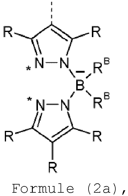
- Composé selon une ou plusieurs des revendications 1 à 3, caractérisé en ce que le ligand partiel L1 présente une structure de formule (2c)
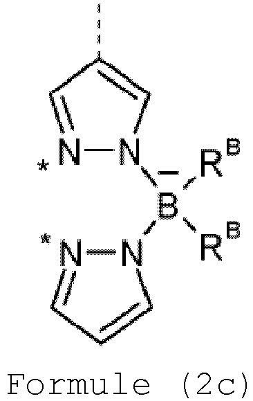
- Composé selon une ou plusieurs des revendications 1 à 4, caractérisé en ce que les substituants RB sont choisis, identiques ou différents à chaque occurrence, dans le groupe constitué par OR1, R1 représentant un groupe alkyle ayant de 1 à 5 atomes de carbone, un groupe alkyle à chaîne droite ayant de 1 à 5 atomes de carbone, un groupe alkyle ramifié ou cyclique ayant de 3 à 6 atomes de carbone, un groupe aryle ayant de 6 à 10 atomes de carbone, qui peut être substitué par un ou plusieurs radicaux R1 de préférence non aromatiques, ou un groupe hétéroaryle ayant de 5 à 10 atomes formant le cycle aromatique, qui peut être substitué par un ou plusieurs radicaux R1 de préférence non aromatiques, les deux radicaux RB pouvant également former l'un avec l'autre un système cyclique ; ou en ce que les deux radicaux RB représentent ensemble aves l'atome de bore, auquel ils sont liés, un groupe conforme à l'une des formules (B-1) à (B-8) suivantes,


- Composé selon une ou plusieurs des revendications 1 à 5, caractérisé en ce que L3 représente un ligand partiel de formule (2), les ligands partiels L1 et L3 pouvant être identiques ou différents.
- Composé selon une ou plusieurs des revendications 1 à 6, caractérisé en ce que L2 comporte un atome de carbone et un atome d'azote en tant qu'atomes coordonnants.
- Composé selon une ou plusieurs des revendications 1 à 7, caractérisé en ce que le ligand partiel L2 représente une structure conforme à l'une des formules (L-1) et (L-2) et en ce que le ligand partiel L3, lorsqu'il est coordonne à l'iridium par l'intermédiaire d'un atome de carbone ou d'un atome d'azote ou par l'intermédiaire de deux atomes de carbone, représente une structure conforme à l'une des formules (L-1) et (L-2),
 CyC est, le même ou différent à chaque occurrence, un groupe aryle ou hétéroaryle substitué ou non substitué ayant de 5 à 14 atomes formant le cycle aromatique, qui est coordonné au métal dans chaque cas par l'intermédiaire d'un atome de carbone et qui est lié à CyD par une liaison covalente ;CyD est, le même ou différent à chaque occurrence, un groupe hétéroaryle substitué ou non substitué ayant de 5 à 14 atomes formant le cycle aromatique, qui est coordonné au métal par l'intermédiaire d'un atome d'azote ou par l'intermédiaire d'un atome de carbone en fonction carbène et qui est lié à CyC par une liaison covalente ;en outre plusieurs substituants peuvent former les uns avec les autres un système cyclique.
 - Composé selon la revendication 8, caractérisé en ce que CyC représente un groupe aryle ou hétéroaryle ayant de 6 à 13 atomes formant le cycle aromatique, qui est coordonné au métal par l'intermédiaire d'un atome de carbone, qui peut être substitué par un ou plusieurs radicaux R et qui est lié à CyD par une liaison covalente, et en ce que CyD représente un groupe hétéroaryle ayant de 5 à 13 atomes formant le cycle aromatique, qui est coordonné au métal par l'intermédiaire d'un atome d'azote neutre ou par l'intermédiaire d'un atome de carbone en fonction carbène et qui peut être substitué par un ou plusieurs radicaux R et qui est lié à CyC par une liaison covalente.
- Composé selon une ou plusieurs des revendications 1 à 9, caractérisé en ce que le ligand partiel L2 est substitué par un substituant de formule (52) ou (53),

 R' est choisi, le même ou différent à chaque occurrence, dans le groupe constitué par H, D, F, CN, un groupe alkyle à chaîne droite ayant de 1 à 10 atomes de carbone, dans lequel également un ou plusieurs atomes d'hydrogène peuvent être remplacés par D ou F, ou un groupe alkyle ramifié ou cyclique ayant de 3 à 10 atomes de carbone, dans lequel également un ou plusieurs atomes d'hydrogène peuvent être remplacés par D ou F, ou un groupe alcényle ayant de 2 à 10 atomes de carbone, dans lequel également un ou plusieurs atomes d'hydrogène peuvent être remplacés par D ou F ; en outre deux radicaux R' contigus ou deux radicaux R' sur des groupes phényle contigus peuvent également former l'un avec l'autre un système cyclique ; ou deux radicaux R' sur des groupes phényle contigus représentent ensemble un groupe choisi parmi O et S, de sorte que les deux cycles phényle forment ensemble avec le groupe pontant un dibenzofurane ou dibenzothiophène, et les autres radicaux R' sont tels que définis précédemment ;n est 0, 1, 2, 3, 4 ou 5.
 - Procédé destiné à la préparation d'un composé selon une ou plusieurs des revendications 1 à 10, caractérisé en ce qu'on fait réagir un sel d'iridium avec un précurseur de ligand en présence d'un synthon borate de triazolyle et en présence d'un capteur d'halogène.
- Formulation contenant au moins un composé selon une ou plusieurs des revendications 1 à 10 et au moins un solvant et/ou au moins un autre composé organique ou inorganique.
- Utilisation d'un composé selon une ou plusieurs des revendications 1 à 10 dans un dispositif électronique ou en tant que sensibilisateur à l'oxygène ou en tant que photoamorceur ou photocatalyseur.
- Dispositif électronique contenant au moins un composé selon une ou plusieurs des revendications 1 à 10.
- Dispositif électronique selon la revendication 14, caractérisé en ce qu'il s'agit d'un dispositif d'électroluminescence organique et le composé selon une ou plusieurs des revendications 1 à 10 est présent conjointement avec un matériau de matrice dans une ou plusieurs couches émettrices.
Applications Claiming Priority (2)
| Application Number | Priority Date | Filing Date | Title |
|---|---|---|---|
| EP17206950 | 2017-12-13 | ||
| PCT/EP2018/084094 WO2019115423A1 (fr) | 2017-12-13 | 2018-12-10 | Complexes métalliques |
Publications (2)
| Publication Number | Publication Date |
|---|---|
| EP3724202A1 EP3724202A1 (fr) | 2020-10-21 |
| EP3724202B1 true EP3724202B1 (fr) | 2022-08-17 |
Family
ID=60673348
Family Applications (1)
| Application Number | Title | Priority Date | Filing Date |
|---|---|---|---|
| EP18811859.0A Active EP3724202B1 (fr) | 2017-12-13 | 2018-12-10 | Complexes métalliques |
Country Status (7)
| Country | Link |
|---|---|
| US (2) | US11659763B2 (fr) |
| EP (1) | EP3724202B1 (fr) |
| JP (1) | JP7293228B2 (fr) |
| KR (1) | KR20200098574A (fr) |
| CN (1) | CN111406062B (fr) |
| TW (1) | TWI791701B (fr) |
| WO (1) | WO2019115423A1 (fr) |
Families Citing this family (59)
| Publication number | Priority date | Publication date | Assignee | Title |
|---|---|---|---|---|
| TWI776926B (zh) * | 2017-07-25 | 2022-09-11 | 德商麥克專利有限公司 | 金屬錯合物 |
| KR20210089205A (ko) | 2018-11-06 | 2021-07-15 | 메르크 파텐트 게엠베하 | Oled 용 유기 전계 발광 재료로서 5,6-디페닐-5,6-디히드로디벤즈[c,e][1,2]아자포스포린 및 6-페닐-6h-디벤조[c,e][1,2]티아진-5,5-디옥사이드 유도체 및 유사한 화합물 |
| TW202035345A (zh) | 2019-01-17 | 2020-10-01 | 德商麥克專利有限公司 | 用於有機電致發光裝置之材料 |
| WO2021013775A1 (fr) | 2019-07-22 | 2021-01-28 | Merck Patent Gmbh | Procédé de production de composés métalliques ortho-metallés |
| EP4021903A1 (fr) | 2019-08-26 | 2022-07-06 | Merck Patent GmbH | Matériaux pour dispositifs électroluminescents organiques |
| WO2021043703A1 (fr) | 2019-09-02 | 2021-03-11 | Merck Patent Gmbh | Matériaux pour dispositifs électroluminescents organiques |
| WO2021078710A1 (fr) | 2019-10-22 | 2021-04-29 | Merck Patent Gmbh | Matériaux pour dispositifs électroluminescents organiques |
| EP4048675A1 (fr) | 2019-10-25 | 2022-08-31 | Merck Patent GmbH | Composés pouvant être utilisés dans un dispositif électronique organique |
| TW202136471A (zh) | 2019-12-17 | 2021-10-01 | 德商麥克專利有限公司 | 有機電致發光裝置用的材料 |
| CN114787169A (zh) | 2019-12-18 | 2022-07-22 | 默克专利有限公司 | 用于有机电致发光器件的芳族化合物 |
| JP2023506570A (ja) | 2019-12-19 | 2023-02-16 | メルク パテント ゲゼルシャフト ミット ベシュレンクテル ハフツング | 有機エレクトロルミネッセンス素子のための多環式化合物 |
| EP4110884A1 (fr) | 2020-02-25 | 2023-01-04 | Merck Patent GmbH | Utilisation de composés hétérocycliques dans un dispositif électronique organique |
| CN115244728A (zh) | 2020-03-02 | 2022-10-25 | 默克专利有限公司 | 砜化合物在有机电子器件中的用途 |
| CN115298187A (zh) | 2020-03-17 | 2022-11-04 | 默克专利有限公司 | 用于有机电致发光器件的杂芳族化合物 |
| CN115298847A (zh) | 2020-03-17 | 2022-11-04 | 默克专利有限公司 | 用于有机电致发光器件的杂环化合物 |
| EP4126880A1 (fr) | 2020-03-26 | 2023-02-08 | Merck Patent GmbH | Composés cycliques pour dispositifs électroluminescents organiques |
| KR20220162156A (ko) | 2020-04-02 | 2022-12-07 | 메르크 파텐트 게엠베하 | 유기 전계 발광 디바이스용 재료 |
| US20230183269A1 (en) | 2020-04-06 | 2023-06-15 | Merck Patent Gmbh | Polycyclic compounds for organic electroluminescent devices |
| TW202210606A (zh) | 2020-05-29 | 2022-03-16 | 德商麥克專利有限公司 | 有機電致發光裝置 |
| EP4169082A1 (fr) | 2020-06-23 | 2023-04-26 | Merck Patent GmbH | Procédé de production d'un mélange |
| EP4172164A1 (fr) | 2020-06-29 | 2023-05-03 | Merck Patent GmbH | Composés hétéroaromatiques pour dispositifs électroluminescents organiques |
| CN115916794A (zh) | 2020-06-29 | 2023-04-04 | 默克专利有限公司 | 用于有机电致发光器件的杂环化合物 |
| CN116157402A (zh) | 2020-08-06 | 2023-05-23 | 默克专利有限公司 | 用于有机电致发光器件的材料 |
| CN116134113A (zh) | 2020-08-13 | 2023-05-16 | 默克专利有限公司 | 金属络合物 |
| KR20230053629A (ko) | 2020-08-18 | 2023-04-21 | 메르크 파텐트 게엠베하 | 유기 전계 발광 디바이스용 재료 |
| JP2023539825A (ja) | 2020-08-19 | 2023-09-20 | メルク パテント ゲーエムベーハー | 有機エレクトロルミネッセントデバイスのための材料 |
| TW202222748A (zh) | 2020-09-30 | 2022-06-16 | 德商麥克專利有限公司 | 用於結構化有機電致發光裝置的功能層之化合物 |
| TW202229215A (zh) | 2020-09-30 | 2022-08-01 | 德商麥克專利有限公司 | 用於有機電致發光裝置功能層之結構化的化合物 |
| KR20230088748A (ko) | 2020-10-16 | 2023-06-20 | 메르크 파텐트 게엠베하 | 유기 전계 발광 디바이스용 헤테로원자를 포함하는 화합물 |
| KR20230088415A (ko) | 2020-10-16 | 2023-06-19 | 메르크 파텐트 게엠베하 | 유기 전계 발광 디바이스용 복소환 화합물 |
| WO2022122682A2 (fr) | 2020-12-10 | 2022-06-16 | Merck Patent Gmbh | Matériaux pour dispositifs électroluminescents organiques |
| TW202241900A (zh) | 2020-12-18 | 2022-11-01 | 德商麥克專利有限公司 | 用於有機電致發光裝置之含氮雜芳烴 |
| KR20230122094A (ko) | 2020-12-18 | 2023-08-22 | 메르크 파텐트 게엠베하 | Oled에 사용하기 위한 청색 형광 방출체로서의 인돌로[3.2.1-jk]카르바졸-6-카르보니트릴유도체 |
| EP4263543A1 (fr) | 2020-12-18 | 2023-10-25 | Merck Patent GmbH | Composés azotés pour dispositifs électroluminescents organiques |
| KR20230129470A (ko) | 2021-01-05 | 2023-09-08 | 메르크 파텐트 게엠베하 | 유기 전계발광 디바이스용 재료 |
| CN117203191A (zh) | 2021-04-29 | 2023-12-08 | 默克专利有限公司 | 用于有机电致发光器件的材料 |
| KR20240005806A (ko) | 2021-04-29 | 2024-01-12 | 메르크 파텐트 게엠베하 | 유기 전계발광 디바이스용 재료 |
| KR20240005791A (ko) | 2021-04-30 | 2024-01-12 | 메르크 파텐트 게엠베하 | 유기 전계 발광 디바이스용 질소 함유 복소환 화합물 |
| CN117355364A (zh) | 2021-05-21 | 2024-01-05 | 默克专利有限公司 | 用于连续纯化至少一种功能材料的方法和用于连续纯化至少一种功能材料的装置 |
| WO2022200638A1 (fr) | 2021-07-06 | 2022-09-29 | Merck Patent Gmbh | Matériaux pour dispositifs électroluminescents organiques |
| CN117917983A (zh) | 2021-09-13 | 2024-04-23 | 默克专利有限公司 | 有机电致发光器件的材料 |
| WO2023041454A1 (fr) | 2021-09-14 | 2023-03-23 | Merck Patent Gmbh | Composés hétérocycliques contenant du bore pour dispositifs électroluminescents organiques |
| WO2023052314A1 (fr) | 2021-09-28 | 2023-04-06 | Merck Patent Gmbh | Matériaux pour dispositifs électroniques |
| WO2023052313A1 (fr) | 2021-09-28 | 2023-04-06 | Merck Patent Gmbh | Matériaux pour dispositifs électroniques |
| WO2023052275A1 (fr) | 2021-09-28 | 2023-04-06 | Merck Patent Gmbh | Matériaux pour dispositifs électroniques |
| WO2023052272A1 (fr) | 2021-09-28 | 2023-04-06 | Merck Patent Gmbh | Matériaux pour dispositifs électroniques |
| WO2023072799A1 (fr) | 2021-10-27 | 2023-05-04 | Merck Patent Gmbh | Composés hétérocycliques contenant du bore et de l'azote pour dispositifs électroluminescents organiques |
| WO2023094412A1 (fr) | 2021-11-25 | 2023-06-01 | Merck Patent Gmbh | Matériaux pour dispositifs électroniques |
| WO2023110742A1 (fr) | 2021-12-13 | 2023-06-22 | Merck Patent Gmbh | Matériaux pour dispositifs électroluminescents organiques |
| WO2023117837A1 (fr) | 2021-12-21 | 2023-06-29 | Merck Patent Gmbh | Procédé de préparation de composés organiques deutériés |
| WO2023152063A1 (fr) | 2022-02-09 | 2023-08-17 | Merck Patent Gmbh | Matériaux pour dispositifs électroluminescents organiques |
| WO2023152346A1 (fr) | 2022-02-14 | 2023-08-17 | Merck Patent Gmbh | Matériaux pour dispositifs électroniques |
| WO2023161168A1 (fr) | 2022-02-23 | 2023-08-31 | Merck Patent Gmbh | Hétérocycles aromatiques pour dispositifs électroluminescents organiques |
| WO2023161167A1 (fr) | 2022-02-23 | 2023-08-31 | Merck Patent Gmbh | Hétérocycles azotés pour dispositifs électroluminescents organiques |
| WO2023222559A1 (fr) | 2022-05-18 | 2023-11-23 | Merck Patent Gmbh | Procédé de préparation de composés organiques deutérés |
| WO2023247662A1 (fr) | 2022-06-24 | 2023-12-28 | Merck Patent Gmbh | Composition pour dispositifs électroniques organiques |
| WO2023247663A1 (fr) | 2022-06-24 | 2023-12-28 | Merck Patent Gmbh | Composition pour dispositifs électroniques organiques |
| WO2024013004A1 (fr) | 2022-07-11 | 2024-01-18 | Merck Patent Gmbh | Matériaux pour dispositifs électroniques |
| WO2024033282A1 (fr) | 2022-08-09 | 2024-02-15 | Merck Patent Gmbh | Matériaux pour dispositifs électroluminescents organiques |
Family Cites Families (69)
| Publication number | Priority date | Publication date | Assignee | Title |
|---|---|---|---|---|
| US5061569A (en) | 1990-07-26 | 1991-10-29 | Eastman Kodak Company | Electroluminescent device with organic electroluminescent medium |
| JP3295088B2 (ja) | 1993-09-29 | 2002-06-24 | 出光興産株式会社 | 有機エレクトロルミネッセンス素子 |
| JPH07133483A (ja) | 1993-11-09 | 1995-05-23 | Shinko Electric Ind Co Ltd | El素子用有機発光材料及びel素子 |
| KR100377321B1 (ko) | 1999-12-31 | 2003-03-26 | 주식회사 엘지화학 | 피-형 반도체 성질을 갖는 유기 화합물을 포함하는 전기소자 |
| US6660410B2 (en) | 2000-03-27 | 2003-12-09 | Idemitsu Kosan Co., Ltd. | Organic electroluminescence element |
| DE10058578C2 (de) | 2000-11-20 | 2002-11-28 | Univ Dresden Tech | Lichtemittierendes Bauelement mit organischen Schichten |
| WO2002051850A1 (fr) | 2000-12-22 | 2002-07-04 | Covion Organic Semiconductors Gmbh | Composes spiro a base de bore et d'aluminium et leur utilisation dans l'industrie electronique |
| US6597012B2 (en) | 2001-05-02 | 2003-07-22 | Junji Kido | Organic electroluminescent device |
| ITRM20020411A1 (it) | 2002-08-01 | 2004-02-02 | Univ Roma La Sapienza | Derivati dello spirobifluorene, loro preparazione e loro uso. |
| DE10249723A1 (de) | 2002-10-25 | 2004-05-06 | Covion Organic Semiconductors Gmbh | Arylamin-Einheiten enthaltende konjugierte Polymere, deren Darstellung und Verwendung |
| KR101030158B1 (ko) | 2002-12-23 | 2011-04-18 | 메르크 파텐트 게엠베하 | 유기 전자발광 부품 |
| JP4411851B2 (ja) | 2003-03-19 | 2010-02-10 | コニカミノルタホールディングス株式会社 | 有機エレクトロルミネッセンス素子 |
| DE10314102A1 (de) | 2003-03-27 | 2004-10-14 | Covion Organic Semiconductors Gmbh | Verfahren zur Herstellung von hochreinen Organo-Iridium-Verbindungen |
| EP1618170A2 (fr) | 2003-04-15 | 2006-01-25 | Covion Organic Semiconductors GmbH | Melanges de semi-conducteurs organiques aptes a l'emission et de matieres matricielles, leur utilisation et composants electroniques contenant ces melanges |
| EP1617711B1 (fr) | 2003-04-23 | 2016-08-17 | Konica Minolta Holdings, Inc. | Dispositif organique électroluminescent et affichage |
| DE10333232A1 (de) | 2003-07-21 | 2007-10-11 | Merck Patent Gmbh | Organisches Elektrolumineszenzelement |
| US7795801B2 (en) | 2003-09-30 | 2010-09-14 | Konica Minolta Holdings, Inc. | Organic electroluminescent element, illuminator, display and compound |
| US7790890B2 (en) | 2004-03-31 | 2010-09-07 | Konica Minolta Holdings, Inc. | Organic electroluminescence element material, organic electroluminescence element, display device and illumination device |
| KR100787425B1 (ko) | 2004-11-29 | 2007-12-26 | 삼성에스디아이 주식회사 | 페닐카바졸계 화합물 및 이를 이용한 유기 전계 발광 소자 |
| DE102004023277A1 (de) | 2004-05-11 | 2005-12-01 | Covion Organic Semiconductors Gmbh | Neue Materialmischungen für die Elektrolumineszenz |
| JP4862248B2 (ja) | 2004-06-04 | 2012-01-25 | コニカミノルタホールディングス株式会社 | 有機エレクトロルミネッセンス素子、照明装置及び表示装置 |
| ITRM20040352A1 (it) | 2004-07-15 | 2004-10-15 | Univ Roma La Sapienza | Derivati oligomerici dello spirobifluorene, loro preparazione e loro uso. |
| KR101249172B1 (ko) | 2004-07-30 | 2013-03-29 | 산요덴키가부시키가이샤 | 유기 일렉트로루미네센스 소자 |
| JP2006135145A (ja) | 2004-11-08 | 2006-05-25 | Sony Corp | 表示素子用有機材料および表示素子 |
| JP4747558B2 (ja) | 2004-11-08 | 2011-08-17 | ソニー株式会社 | 表示素子用有機材料および表示素子 |
| JP4358884B2 (ja) | 2005-03-18 | 2009-11-04 | 出光興産株式会社 | 芳香族アミン誘導体及びそれを用いた有機エレクトロルミネッセンス素子 |
| US8674141B2 (en) | 2005-05-03 | 2014-03-18 | Merck Patent Gmbh | Organic electroluminescent device and boric acid and borinic acid derivatives used therein |
| DE102005023437A1 (de) | 2005-05-20 | 2006-11-30 | Merck Patent Gmbh | Verbindungen für organische elektronische Vorrichtungen |
| JP4593631B2 (ja) | 2005-12-01 | 2010-12-08 | 新日鐵化学株式会社 | 有機電界発光素子用化合物及び有機電界発光素子 |
| DE102006025777A1 (de) | 2006-05-31 | 2007-12-06 | Merck Patent Gmbh | Neue Materialien für organische Elektrolumineszenzvorrichtungen |
| DE102006025846A1 (de) | 2006-06-02 | 2007-12-06 | Merck Patent Gmbh | Neue Materialien für organische Elektrolumineszenzvorrichtungen |
| DE102006031990A1 (de) | 2006-07-11 | 2008-01-17 | Merck Patent Gmbh | Neue Materialien für organische Elektrolumineszenzvorrichtungen |
| CN101511834B (zh) | 2006-11-09 | 2013-03-27 | 新日铁化学株式会社 | 有机场致发光元件用化合物及有机场致发光元件 |
| DE102007002714A1 (de) | 2007-01-18 | 2008-07-31 | Merck Patent Gmbh | Neue Materialien für organische Elektrolumineszenzvorrichtungen |
| DE102007053771A1 (de) | 2007-11-12 | 2009-05-14 | Merck Patent Gmbh | Organische Elektrolumineszenzvorrichtungen |
| US7862908B2 (en) | 2007-11-26 | 2011-01-04 | National Tsing Hua University | Conjugated compounds containing hydroindoloacridine structural elements, and their use |
| US8221905B2 (en) | 2007-12-28 | 2012-07-17 | Universal Display Corporation | Carbazole-containing materials in phosphorescent light emitting diodes |
| WO2009148015A1 (fr) | 2008-06-05 | 2009-12-10 | 出光興産株式会社 | Composé halogéné, composé polycyclique, et élément électroluminescent organique comprenant le composé polycyclique |
| DE102008033943A1 (de) | 2008-07-18 | 2010-01-21 | Merck Patent Gmbh | Neue Materialien für organische Elektrolumineszenzvorrichtungen |
| DE102008036982A1 (de) | 2008-08-08 | 2010-02-11 | Merck Patent Gmbh | Organische Elektrolumineszenzvorrichtung |
| KR101506919B1 (ko) | 2008-10-31 | 2015-03-30 | 롬엔드하스전자재료코리아유한회사 | 신규한 유기 전자재료용 화합물 및 이를 포함하는 유기 전자 소자 |
| US8865321B2 (en) | 2008-11-11 | 2014-10-21 | Merck Patent Gmbh | Organic electroluminescent devices |
| DE102008056688A1 (de) | 2008-11-11 | 2010-05-12 | Merck Patent Gmbh | Materialien für organische Elektrolumineszenzvorrichtungen |
| DE102009014513A1 (de) | 2009-03-23 | 2010-09-30 | Merck Patent Gmbh | Organische Elektrolumineszenzvorrichtung |
| DE102009023155A1 (de) | 2009-05-29 | 2010-12-02 | Merck Patent Gmbh | Materialien für organische Elektrolumineszenzvorrichtungen |
| DE102009031021A1 (de) | 2009-06-30 | 2011-01-05 | Merck Patent Gmbh | Materialien für organische Elektrolumineszenzvorrichtungen |
| DE102009048791A1 (de) | 2009-10-08 | 2011-04-14 | Merck Patent Gmbh | Materialien für organische Elektrolumineszenzvorrichtungen |
| DE102010005697A1 (de) | 2010-01-25 | 2011-07-28 | Merck Patent GmbH, 64293 | Verbindungen für elektronische Vorrichtungen |
| WO2012008550A1 (fr) | 2010-07-16 | 2012-01-19 | 住友化学株式会社 | Composé polymère, composition contenant le composé polymère, composition liquide, élément et film minces, et source lumineuse de surface et dispositif d'affichage utilisant l'élément |
| DE102010045405A1 (de) | 2010-09-15 | 2012-03-15 | Merck Patent Gmbh | Materialien für organische Elektrolumineszenzvorrichtungen |
| DE102010048498A1 (de) | 2010-10-14 | 2012-04-19 | Merck Patent Gmbh | Materialien für organische Elektrolumineszenzvorrichtungen |
| US9627626B2 (en) | 2011-01-13 | 2017-04-18 | Merck Patent Gmbh | Compounds for organic electroluminescent devices |
| US10056549B2 (en) | 2011-05-05 | 2018-08-21 | Merck Patent Gmbh | Compounds for electronic devices |
| JP6081473B2 (ja) | 2011-11-17 | 2017-02-15 | メルク パテント ゲーエムベーハー | スピロジヒドロアクリジンおよび有機エレクトロルミネッセンス素子のための材料としてのそれの使用 |
| JP5920013B2 (ja) | 2012-05-21 | 2016-05-18 | コニカミノルタ株式会社 | 有機エレクトロルミネッセンス素子、有機エレクトロルミネッセンス素子の製造方法、表示装置および照明装置 |
| KR20210097213A (ko) | 2012-07-23 | 2021-08-06 | 메르크 파텐트 게엠베하 | 2-디아릴아미노플루오렌의 유도체 및 이를 함유하는 유기 전자 화합물 |
| KR102006621B1 (ko) | 2012-07-23 | 2019-08-02 | 메르크 파텐트 게엠베하 | 화합물 및 유기 전계 발광 디바이스 |
| KR102155492B1 (ko) | 2012-07-23 | 2020-09-14 | 메르크 파텐트 게엠베하 | 플루오렌 및 이를 함유하는 전자 소자 |
| US20150243910A1 (en) * | 2012-08-31 | 2015-08-27 | Solvay Sa | Transition metal complexes comprising asymmetric tetradentate ligands |
| WO2014033044A1 (fr) * | 2012-08-31 | 2014-03-06 | Solvay Sa | Complexes de métal de transition comprenant des ligands tétradentates symétriques |
| JP6449162B2 (ja) | 2012-10-09 | 2019-01-09 | メルク パテント ゲーエムベーハー | 電子素子 |
| KR102179608B1 (ko) | 2012-12-18 | 2020-11-17 | 메르크 파텐트 게엠베하 | 유기 전계발광 소자 |
| DE102013215342B4 (de) | 2013-08-05 | 2023-05-04 | Novaled Gmbh | Verfahren zur Herstellung organisch phosphoreszenter Schichten unter Zusatz schwerer Hauptgruppenmetallkomplexe, damit hergestellte Schicht, deren Verwendung und organisches Halbleiterbauelement diese umfassend |
| WO2015049030A2 (fr) | 2013-10-02 | 2015-04-09 | Merck Patent Gmbh | Composés contenant du bore |
| WO2015169412A1 (fr) | 2014-05-05 | 2015-11-12 | Merck Patent Gmbh | Matières pour des dispositifs organiques électroluminescents |
| JP6772188B2 (ja) * | 2015-02-03 | 2020-10-21 | メルク、パテント、ゲゼルシャフト、ミット、ベシュレンクテル、ハフツングMerck Patent GmbH | 金属錯体 |
| US10629817B2 (en) | 2015-05-18 | 2020-04-21 | Merck Patent Gmbh | Materials for organic electroluminescent devices |
| KR20180044361A (ko) | 2015-08-25 | 2018-05-02 | 메르크 파텐트 게엠베하 | 금속 착물 |
| CN108137633A (zh) | 2015-12-04 | 2018-06-08 | 广州华睿光电材料有限公司 | 金属有机配合物、高聚物、混合物、组合物以及有机电子器件 |
-
2018
- 2018-12-10 JP JP2020531578A patent/JP7293228B2/ja active Active
- 2018-12-10 TW TW107144283A patent/TWI791701B/zh active
- 2018-12-10 CN CN201880076935.4A patent/CN111406062B/zh active Active
- 2018-12-10 US US16/771,537 patent/US11659763B2/en active Active
- 2018-12-10 KR KR1020207019441A patent/KR20200098574A/ko not_active Application Discontinuation
- 2018-12-10 EP EP18811859.0A patent/EP3724202B1/fr active Active
- 2018-12-10 WO PCT/EP2018/084094 patent/WO2019115423A1/fr unknown
-
2023
- 2023-05-19 US US18/320,715 patent/US20230320191A1/en active Pending
Also Published As
| Publication number | Publication date |
|---|---|
| JP2021506759A (ja) | 2021-02-22 |
| US20210175441A1 (en) | 2021-06-10 |
| WO2019115423A1 (fr) | 2019-06-20 |
| JP7293228B2 (ja) | 2023-06-19 |
| US11659763B2 (en) | 2023-05-23 |
| KR20200098574A (ko) | 2020-08-20 |
| US20230320191A1 (en) | 2023-10-05 |
| TW201936621A (zh) | 2019-09-16 |
| CN111406062B (zh) | 2024-01-19 |
| EP3724202A1 (fr) | 2020-10-21 |
| TWI791701B (zh) | 2023-02-11 |
| CN111406062A (zh) | 2020-07-10 |
Similar Documents
| Publication | Publication Date | Title |
|---|---|---|
| EP3724202B1 (fr) | Complexes métalliques | |
| EP3768692B1 (fr) | Complexes métalliques | |
| EP3658564B1 (fr) | Complexes métalliques | |
| EP3487865B1 (fr) | Complexes métalliques dinucléaires et oligonucléaires comprenant des sous-unités de ligands tripodes bidentées ainsi que leur utilisation dans des dispositifs électroniques | |
| EP3180411B1 (fr) | Matériaux pour dispositifs électroluminescents organiques | |
| EP3140302B1 (fr) | Matières pour des dispositifs organiques électroluminescents | |
| EP2714704B1 (fr) | Complexes métalliques | |
| EP2883422B1 (fr) | Matériaux pour dispositifs organiques à électroluminescence | |
| EP3027708B1 (fr) | Matériaux pour dispositifs électroniques | |
| EP2935293B1 (fr) | Complexes du iridium et leur utilisation dans les dispositifs electroniques en particulier les dispositifs electroluminescentes | |
| EP2663567B1 (fr) | Composés pour des dispositifs électroluminescents organiques | |
| EP2344609B1 (fr) | Matières pour des dispositifs électroluminescents organiques | |
| EP3752512A1 (fr) | Complexes métalliques | |
| WO2018069197A1 (fr) | Complexes métalliques | |
| EP3515925A1 (fr) | Complexes métalliques trouvant application comme émetteurs dans des dispositifs électroluminescents organiques | |
| WO2017148565A1 (fr) | Matériaux pour dispositifs électroluminescents organiques | |
| EP3478698A1 (fr) | Procédé pour séparer des mélanges d'énantiomères de complexes métalliques | |
| EP3548467B1 (fr) | Composés à structures valérolactame | |
| EP3371274B1 (fr) | Matériaux pour dispositifs électroluminescents organiques | |
| EP3016952B1 (fr) | Composés de lactame spirocondensés pour des dispositifs électroluminescents organiques | |
| DE102009053645A1 (de) | Materialien für organische Elektrolumineszenzvorrichtung | |
| WO2017025164A1 (fr) | Matériaux pour dispositifs électroluminescents organiques | |
| EP3596065A1 (fr) | Composés ayant de structures arylamine | |
| EP2906567A1 (fr) | Composés complexés azabicycliques aromatiques comportant les éléments cu, ag, au, zn, al conçus pour être utilisés dans des dispositifs électroluminescents | |
| WO2018050583A1 (fr) | Composés à structures carbazole |
Legal Events
| Date | Code | Title | Description |
|---|---|---|---|
| STAA | Information on the status of an ep patent application or granted ep patent |
Free format text: STATUS: UNKNOWN |
|
| STAA | Information on the status of an ep patent application or granted ep patent |
Free format text: STATUS: THE INTERNATIONAL PUBLICATION HAS BEEN MADE |
|
| PUAI | Public reference made under article 153(3) epc to a published international application that has entered the european phase |
Free format text: ORIGINAL CODE: 0009012 |
|
| STAA | Information on the status of an ep patent application or granted ep patent |
Free format text: STATUS: REQUEST FOR EXAMINATION WAS MADE |
|
| 17P | Request for examination filed |
Effective date: 20200610 |
|
| AK | Designated contracting states |
Kind code of ref document: A1 Designated state(s): AL AT BE BG CH CY CZ DE DK EE ES FI FR GB GR HR HU IE IS IT LI LT LU LV MC MK MT NL NO PL PT RO RS SE SI SK SM TR |
|
| AX | Request for extension of the european patent |
Extension state: BA ME |
|
| DAV | Request for validation of the european patent (deleted) | ||
| DAX | Request for extension of the european patent (deleted) | ||
| STAA | Information on the status of an ep patent application or granted ep patent |
Free format text: STATUS: EXAMINATION IS IN PROGRESS |
|
| 17Q | First examination report despatched |
Effective date: 20210406 |
|
| GRAP | Despatch of communication of intention to grant a patent |
Free format text: ORIGINAL CODE: EPIDOSNIGR1 |
|
| STAA | Information on the status of an ep patent application or granted ep patent |
Free format text: STATUS: GRANT OF PATENT IS INTENDED |
|
| RIC1 | Information provided on ipc code assigned before grant |
Ipc: H01L 51/00 20060101ALI20220225BHEP Ipc: H01L 51/50 20060101ALI20220225BHEP Ipc: C07F 15/00 20060101AFI20220225BHEP |
|
| INTG | Intention to grant announced |
Effective date: 20220405 |
|
| GRAS | Grant fee paid |
Free format text: ORIGINAL CODE: EPIDOSNIGR3 |
|
| GRAA | (expected) grant |
Free format text: ORIGINAL CODE: 0009210 |
|
| STAA | Information on the status of an ep patent application or granted ep patent |
Free format text: STATUS: THE PATENT HAS BEEN GRANTED |
|
| AK | Designated contracting states |
Kind code of ref document: B1 Designated state(s): AL AT BE BG CH CY CZ DE DK EE ES FI FR GB GR HR HU IE IS IT LI LT LU LV MC MK MT NL NO PL PT RO RS SE SI SK SM TR |
|
| REG | Reference to a national code |
Ref country code: CH Ref legal event code: EP |
|
| REG | Reference to a national code |
Ref country code: DE Ref legal event code: R096 Ref document number: 502018010441 Country of ref document: DE |
|
| REG | Reference to a national code |
Ref country code: IE Ref legal event code: FG4D Free format text: LANGUAGE OF EP DOCUMENT: GERMAN |
|
| REG | Reference to a national code |
Ref country code: AT Ref legal event code: REF Ref document number: 1512110 Country of ref document: AT Kind code of ref document: T Effective date: 20220915 |
|
| REG | Reference to a national code |
Ref country code: NL Ref legal event code: MP Effective date: 20220817 |
|
| REG | Reference to a national code |
Ref country code: LT Ref legal event code: MG9D |
|
| PG25 | Lapsed in a contracting state [announced via postgrant information from national office to epo] |
Ref country code: SE Free format text: LAPSE BECAUSE OF FAILURE TO SUBMIT A TRANSLATION OF THE DESCRIPTION OR TO PAY THE FEE WITHIN THE PRESCRIBED TIME-LIMIT Effective date: 20220817 Ref country code: RS Free format text: LAPSE BECAUSE OF FAILURE TO SUBMIT A TRANSLATION OF THE DESCRIPTION OR TO PAY THE FEE WITHIN THE PRESCRIBED TIME-LIMIT Effective date: 20220817 Ref country code: PT Free format text: LAPSE BECAUSE OF FAILURE TO SUBMIT A TRANSLATION OF THE DESCRIPTION OR TO PAY THE FEE WITHIN THE PRESCRIBED TIME-LIMIT Effective date: 20221219 Ref country code: NO Free format text: LAPSE BECAUSE OF FAILURE TO SUBMIT A TRANSLATION OF THE DESCRIPTION OR TO PAY THE FEE WITHIN THE PRESCRIBED TIME-LIMIT Effective date: 20221117 Ref country code: NL Free format text: LAPSE BECAUSE OF FAILURE TO SUBMIT A TRANSLATION OF THE DESCRIPTION OR TO PAY THE FEE WITHIN THE PRESCRIBED TIME-LIMIT Effective date: 20220817 Ref country code: LV Free format text: LAPSE BECAUSE OF FAILURE TO SUBMIT A TRANSLATION OF THE DESCRIPTION OR TO PAY THE FEE WITHIN THE PRESCRIBED TIME-LIMIT Effective date: 20220817 Ref country code: LT Free format text: LAPSE BECAUSE OF FAILURE TO SUBMIT A TRANSLATION OF THE DESCRIPTION OR TO PAY THE FEE WITHIN THE PRESCRIBED TIME-LIMIT Effective date: 20220817 Ref country code: FI Free format text: LAPSE BECAUSE OF FAILURE TO SUBMIT A TRANSLATION OF THE DESCRIPTION OR TO PAY THE FEE WITHIN THE PRESCRIBED TIME-LIMIT Effective date: 20220817 |
|
| PG25 | Lapsed in a contracting state [announced via postgrant information from national office to epo] |
Ref country code: PL Free format text: LAPSE BECAUSE OF FAILURE TO SUBMIT A TRANSLATION OF THE DESCRIPTION OR TO PAY THE FEE WITHIN THE PRESCRIBED TIME-LIMIT Effective date: 20220817 Ref country code: IS Free format text: LAPSE BECAUSE OF FAILURE TO SUBMIT A TRANSLATION OF THE DESCRIPTION OR TO PAY THE FEE WITHIN THE PRESCRIBED TIME-LIMIT Effective date: 20221217 Ref country code: HR Free format text: LAPSE BECAUSE OF FAILURE TO SUBMIT A TRANSLATION OF THE DESCRIPTION OR TO PAY THE FEE WITHIN THE PRESCRIBED TIME-LIMIT Effective date: 20220817 Ref country code: GR Free format text: LAPSE BECAUSE OF FAILURE TO SUBMIT A TRANSLATION OF THE DESCRIPTION OR TO PAY THE FEE WITHIN THE PRESCRIBED TIME-LIMIT Effective date: 20221118 |
|
| PG25 | Lapsed in a contracting state [announced via postgrant information from national office to epo] |
Ref country code: SM Free format text: LAPSE BECAUSE OF FAILURE TO SUBMIT A TRANSLATION OF THE DESCRIPTION OR TO PAY THE FEE WITHIN THE PRESCRIBED TIME-LIMIT Effective date: 20220817 Ref country code: RO Free format text: LAPSE BECAUSE OF FAILURE TO SUBMIT A TRANSLATION OF THE DESCRIPTION OR TO PAY THE FEE WITHIN THE PRESCRIBED TIME-LIMIT Effective date: 20220817 Ref country code: ES Free format text: LAPSE BECAUSE OF FAILURE TO SUBMIT A TRANSLATION OF THE DESCRIPTION OR TO PAY THE FEE WITHIN THE PRESCRIBED TIME-LIMIT Effective date: 20220817 Ref country code: DK Free format text: LAPSE BECAUSE OF FAILURE TO SUBMIT A TRANSLATION OF THE DESCRIPTION OR TO PAY THE FEE WITHIN THE PRESCRIBED TIME-LIMIT Effective date: 20220817 Ref country code: CZ Free format text: LAPSE BECAUSE OF FAILURE TO SUBMIT A TRANSLATION OF THE DESCRIPTION OR TO PAY THE FEE WITHIN THE PRESCRIBED TIME-LIMIT Effective date: 20220817 |
|
| REG | Reference to a national code |
Ref country code: DE Ref legal event code: R097 Ref document number: 502018010441 Country of ref document: DE |
|
| PG25 | Lapsed in a contracting state [announced via postgrant information from national office to epo] |
Ref country code: SK Free format text: LAPSE BECAUSE OF FAILURE TO SUBMIT A TRANSLATION OF THE DESCRIPTION OR TO PAY THE FEE WITHIN THE PRESCRIBED TIME-LIMIT Effective date: 20220817 Ref country code: EE Free format text: LAPSE BECAUSE OF FAILURE TO SUBMIT A TRANSLATION OF THE DESCRIPTION OR TO PAY THE FEE WITHIN THE PRESCRIBED TIME-LIMIT Effective date: 20220817 |
|
| PLBE | No opposition filed within time limit |
Free format text: ORIGINAL CODE: 0009261 |
|
| STAA | Information on the status of an ep patent application or granted ep patent |
Free format text: STATUS: NO OPPOSITION FILED WITHIN TIME LIMIT |
|
| P01 | Opt-out of the competence of the unified patent court (upc) registered |
Effective date: 20230519 |
|
| PG25 | Lapsed in a contracting state [announced via postgrant information from national office to epo] |
Ref country code: AL Free format text: LAPSE BECAUSE OF FAILURE TO SUBMIT A TRANSLATION OF THE DESCRIPTION OR TO PAY THE FEE WITHIN THE PRESCRIBED TIME-LIMIT Effective date: 20220817 |
|
| 26N | No opposition filed |
Effective date: 20230519 |
|
| REG | Reference to a national code |
Ref country code: CH Ref legal event code: PL |
|
| GBPC | Gb: european patent ceased through non-payment of renewal fee |
Effective date: 20221210 |
|
| REG | Reference to a national code |
Ref country code: BE Ref legal event code: MM Effective date: 20221231 |
|
| PG25 | Lapsed in a contracting state [announced via postgrant information from national office to epo] |
Ref country code: SI Free format text: LAPSE BECAUSE OF FAILURE TO SUBMIT A TRANSLATION OF THE DESCRIPTION OR TO PAY THE FEE WITHIN THE PRESCRIBED TIME-LIMIT Effective date: 20220817 Ref country code: LU Free format text: LAPSE BECAUSE OF NON-PAYMENT OF DUE FEES Effective date: 20221210 |
|
| REG | Reference to a national code |
Ref country code: DE Ref legal event code: R081 Ref document number: 502018010441 Country of ref document: DE Owner name: UDC IRELAND LTD., IE Free format text: FORMER OWNER: MERCK PATENT GESELLSCHAFT MIT BESCHRAENKTER HAFTUNG, 64293 DARMSTADT, DE |
|
| P03 | Opt-out of the competence of the unified patent court (upc) deleted | ||
| PG25 | Lapsed in a contracting state [announced via postgrant information from national office to epo] |
Ref country code: LI Free format text: LAPSE BECAUSE OF NON-PAYMENT OF DUE FEES Effective date: 20221231 Ref country code: IE Free format text: LAPSE BECAUSE OF NON-PAYMENT OF DUE FEES Effective date: 20221210 Ref country code: GB Free format text: LAPSE BECAUSE OF NON-PAYMENT OF DUE FEES Effective date: 20221210 Ref country code: CH Free format text: LAPSE BECAUSE OF NON-PAYMENT OF DUE FEES Effective date: 20221231 |
|
| PG25 | Lapsed in a contracting state [announced via postgrant information from national office to epo] |
Ref country code: FR Free format text: LAPSE BECAUSE OF NON-PAYMENT OF DUE FEES Effective date: 20221231 Ref country code: BE Free format text: LAPSE BECAUSE OF NON-PAYMENT OF DUE FEES Effective date: 20221231 |
|
| PGFP | Annual fee paid to national office [announced via postgrant information from national office to epo] |
Ref country code: DE Payment date: 20231017 Year of fee payment: 6 |
|
| P01 | Opt-out of the competence of the unified patent court (upc) registered |
Effective date: 20240207 |