EP3609049B1 - Drahtlose ladevorrichtung und drahtloses ladeverfahren - Google Patents
Drahtlose ladevorrichtung und drahtloses ladeverfahren Download PDFInfo
- Publication number
- EP3609049B1 EP3609049B1 EP18780781.3A EP18780781A EP3609049B1 EP 3609049 B1 EP3609049 B1 EP 3609049B1 EP 18780781 A EP18780781 A EP 18780781A EP 3609049 B1 EP3609049 B1 EP 3609049B1
- Authority
- EP
- European Patent Office
- Prior art keywords
- power supply
- charging
- wireless charging
- supply device
- wireless
- Prior art date
- Legal status (The legal status is an assumption and is not a legal conclusion. Google has not performed a legal analysis and makes no representation as to the accuracy of the status listed.)
- Active
Links
- 238000007600 charging Methods 0.000 title claims description 535
- 238000000034 method Methods 0.000 title claims description 39
- 230000006854 communication Effects 0.000 claims description 62
- 238000004891 communication Methods 0.000 claims description 62
- 238000006243 chemical reaction Methods 0.000 claims description 29
- 230000008569 process Effects 0.000 claims description 17
- 230000007175 bidirectional communication Effects 0.000 claims description 2
- 238000010277 constant-current charging Methods 0.000 description 21
- 230000006870 function Effects 0.000 description 15
- 238000010280 constant potential charging Methods 0.000 description 14
- 230000005540 biological transmission Effects 0.000 description 10
- 238000010586 diagram Methods 0.000 description 7
- 230000008878 coupling Effects 0.000 description 5
- 238000010168 coupling process Methods 0.000 description 5
- 238000005859 coupling reaction Methods 0.000 description 5
- 238000005516 engineering process Methods 0.000 description 5
- 230000004044 response Effects 0.000 description 3
- WHXSMMKQMYFTQS-UHFFFAOYSA-N Lithium Chemical compound [Li] WHXSMMKQMYFTQS-UHFFFAOYSA-N 0.000 description 2
- 230000008859 change Effects 0.000 description 2
- 230000002708 enhancing effect Effects 0.000 description 2
- 229910052744 lithium Inorganic materials 0.000 description 2
- 238000007726 management method Methods 0.000 description 2
- 238000012545 processing Methods 0.000 description 2
- 230000005856 abnormality Effects 0.000 description 1
- 230000001413 cellular effect Effects 0.000 description 1
- 230000003247 decreasing effect Effects 0.000 description 1
- 230000001419 dependent effect Effects 0.000 description 1
- 238000013461 design Methods 0.000 description 1
- 238000001514 detection method Methods 0.000 description 1
- 230000005674 electromagnetic induction Effects 0.000 description 1
- 238000001914 filtration Methods 0.000 description 1
- 238000012986 modification Methods 0.000 description 1
- 230000004048 modification Effects 0.000 description 1
- 238000012806 monitoring device Methods 0.000 description 1
- 238000002360 preparation method Methods 0.000 description 1
- 230000002618 waking effect Effects 0.000 description 1
- 239000002699 waste material Substances 0.000 description 1
Images


Classifications
-
- H—ELECTRICITY
- H02—GENERATION; CONVERSION OR DISTRIBUTION OF ELECTRIC POWER
- H02J—CIRCUIT ARRANGEMENTS OR SYSTEMS FOR SUPPLYING OR DISTRIBUTING ELECTRIC POWER; SYSTEMS FOR STORING ELECTRIC ENERGY
- H02J50/00—Circuit arrangements or systems for wireless supply or distribution of electric power
- H02J50/80—Circuit arrangements or systems for wireless supply or distribution of electric power involving the exchange of data, concerning supply or distribution of electric power, between transmitting devices and receiving devices
-
- H—ELECTRICITY
- H02—GENERATION; CONVERSION OR DISTRIBUTION OF ELECTRIC POWER
- H02J—CIRCUIT ARRANGEMENTS OR SYSTEMS FOR SUPPLYING OR DISTRIBUTING ELECTRIC POWER; SYSTEMS FOR STORING ELECTRIC ENERGY
- H02J50/00—Circuit arrangements or systems for wireless supply or distribution of electric power
- H02J50/10—Circuit arrangements or systems for wireless supply or distribution of electric power using inductive coupling
- H02J50/12—Circuit arrangements or systems for wireless supply or distribution of electric power using inductive coupling of the resonant type
-
- H—ELECTRICITY
- H02—GENERATION; CONVERSION OR DISTRIBUTION OF ELECTRIC POWER
- H02J—CIRCUIT ARRANGEMENTS OR SYSTEMS FOR SUPPLYING OR DISTRIBUTING ELECTRIC POWER; SYSTEMS FOR STORING ELECTRIC ENERGY
- H02J50/00—Circuit arrangements or systems for wireless supply or distribution of electric power
- H02J50/90—Circuit arrangements or systems for wireless supply or distribution of electric power involving detection or optimisation of position, e.g. alignment
-
- H—ELECTRICITY
- H02—GENERATION; CONVERSION OR DISTRIBUTION OF ELECTRIC POWER
- H02J—CIRCUIT ARRANGEMENTS OR SYSTEMS FOR SUPPLYING OR DISTRIBUTING ELECTRIC POWER; SYSTEMS FOR STORING ELECTRIC ENERGY
- H02J7/00—Circuit arrangements for charging or depolarising batteries or for supplying loads from batteries
- H02J7/00032—Circuit arrangements for charging or depolarising batteries or for supplying loads from batteries characterised by data exchange
- H02J7/00034—Charger exchanging data with an electronic device, i.e. telephone, whose internal battery is under charge
-
- H—ELECTRICITY
- H02—GENERATION; CONVERSION OR DISTRIBUTION OF ELECTRIC POWER
- H02J—CIRCUIT ARRANGEMENTS OR SYSTEMS FOR SUPPLYING OR DISTRIBUTING ELECTRIC POWER; SYSTEMS FOR STORING ELECTRIC ENERGY
- H02J7/00—Circuit arrangements for charging or depolarising batteries or for supplying loads from batteries
- H02J7/00032—Circuit arrangements for charging or depolarising batteries or for supplying loads from batteries characterised by data exchange
- H02J7/00038—Circuit arrangements for charging or depolarising batteries or for supplying loads from batteries characterised by data exchange using passive battery identification means, e.g. resistors or capacitors
- H02J7/00041—Circuit arrangements for charging or depolarising batteries or for supplying loads from batteries characterised by data exchange using passive battery identification means, e.g. resistors or capacitors in response to measured battery parameters, e.g. voltage, current or temperature profile
-
- H—ELECTRICITY
- H02—GENERATION; CONVERSION OR DISTRIBUTION OF ELECTRIC POWER
- H02J—CIRCUIT ARRANGEMENTS OR SYSTEMS FOR SUPPLYING OR DISTRIBUTING ELECTRIC POWER; SYSTEMS FOR STORING ELECTRIC ENERGY
- H02J7/00—Circuit arrangements for charging or depolarising batteries or for supplying loads from batteries
- H02J7/00032—Circuit arrangements for charging or depolarising batteries or for supplying loads from batteries characterised by data exchange
- H02J7/00045—Authentication, i.e. circuits for checking compatibility between one component, e.g. a battery or a battery charger, and another component, e.g. a power source
-
- H—ELECTRICITY
- H02—GENERATION; CONVERSION OR DISTRIBUTION OF ELECTRIC POWER
- H02J—CIRCUIT ARRANGEMENTS OR SYSTEMS FOR SUPPLYING OR DISTRIBUTING ELECTRIC POWER; SYSTEMS FOR STORING ELECTRIC ENERGY
- H02J7/00—Circuit arrangements for charging or depolarising batteries or for supplying loads from batteries
- H02J7/0029—Circuit arrangements for charging or depolarising batteries or for supplying loads from batteries with safety or protection devices or circuits
- H02J7/00309—Overheat or overtemperature protection
-
- H—ELECTRICITY
- H02—GENERATION; CONVERSION OR DISTRIBUTION OF ELECTRIC POWER
- H02J—CIRCUIT ARRANGEMENTS OR SYSTEMS FOR SUPPLYING OR DISTRIBUTING ELECTRIC POWER; SYSTEMS FOR STORING ELECTRIC ENERGY
- H02J7/00—Circuit arrangements for charging or depolarising batteries or for supplying loads from batteries
- H02J7/0042—Circuit arrangements for charging or depolarising batteries or for supplying loads from batteries characterised by the mechanical construction
- H02J7/0044—Circuit arrangements for charging or depolarising batteries or for supplying loads from batteries characterised by the mechanical construction specially adapted for holding portable devices containing batteries
-
- H—ELECTRICITY
- H02—GENERATION; CONVERSION OR DISTRIBUTION OF ELECTRIC POWER
- H02J—CIRCUIT ARRANGEMENTS OR SYSTEMS FOR SUPPLYING OR DISTRIBUTING ELECTRIC POWER; SYSTEMS FOR STORING ELECTRIC ENERGY
- H02J7/00—Circuit arrangements for charging or depolarising batteries or for supplying loads from batteries
- H02J7/007—Regulation of charging or discharging current or voltage
- H02J7/00712—Regulation of charging or discharging current or voltage the cycle being controlled or terminated in response to electric parameters
- H02J7/00714—Regulation of charging or discharging current or voltage the cycle being controlled or terminated in response to electric parameters in response to battery charging or discharging current
-
- H—ELECTRICITY
- H02—GENERATION; CONVERSION OR DISTRIBUTION OF ELECTRIC POWER
- H02J—CIRCUIT ARRANGEMENTS OR SYSTEMS FOR SUPPLYING OR DISTRIBUTING ELECTRIC POWER; SYSTEMS FOR STORING ELECTRIC ENERGY
- H02J7/00—Circuit arrangements for charging or depolarising batteries or for supplying loads from batteries
- H02J7/007—Regulation of charging or discharging current or voltage
- H02J7/007188—Regulation of charging or discharging current or voltage the charge cycle being controlled or terminated in response to non-electric parameters
- H02J7/007192—Regulation of charging or discharging current or voltage the charge cycle being controlled or terminated in response to non-electric parameters in response to temperature
- H02J7/007194—Regulation of charging or discharging current or voltage the charge cycle being controlled or terminated in response to non-electric parameters in response to temperature of the battery
-
- H—ELECTRICITY
- H02—GENERATION; CONVERSION OR DISTRIBUTION OF ELECTRIC POWER
- H02M—APPARATUS FOR CONVERSION BETWEEN AC AND AC, BETWEEN AC AND DC, OR BETWEEN DC AND DC, AND FOR USE WITH MAINS OR SIMILAR POWER SUPPLY SYSTEMS; CONVERSION OF DC OR AC INPUT POWER INTO SURGE OUTPUT POWER; CONTROL OR REGULATION THEREOF
- H02M3/00—Conversion of dc power input into dc power output
- H02M3/02—Conversion of dc power input into dc power output without intermediate conversion into ac
- H02M3/04—Conversion of dc power input into dc power output without intermediate conversion into ac by static converters
- H02M3/06—Conversion of dc power input into dc power output without intermediate conversion into ac by static converters using resistors or capacitors, e.g. potential divider
- H02M3/07—Conversion of dc power input into dc power output without intermediate conversion into ac by static converters using resistors or capacitors, e.g. potential divider using capacitors charged and discharged alternately by semiconductor devices with control electrode, e.g. charge pumps
-
- H—ELECTRICITY
- H04—ELECTRIC COMMUNICATION TECHNIQUE
- H04B—TRANSMISSION
- H04B5/00—Near-field transmission systems, e.g. inductive or capacitive transmission systems
- H04B5/20—Near-field transmission systems, e.g. inductive or capacitive transmission systems characterised by the transmission technique; characterised by the transmission medium
- H04B5/24—Inductive coupling
-
- H—ELECTRICITY
- H04—ELECTRIC COMMUNICATION TECHNIQUE
- H04B—TRANSMISSION
- H04B5/00—Near-field transmission systems, e.g. inductive or capacitive transmission systems
- H04B5/70—Near-field transmission systems, e.g. inductive or capacitive transmission systems specially adapted for specific purposes
- H04B5/79—Near-field transmission systems, e.g. inductive or capacitive transmission systems specially adapted for specific purposes for data transfer in combination with power transfer
-
- H—ELECTRICITY
- H02—GENERATION; CONVERSION OR DISTRIBUTION OF ELECTRIC POWER
- H02J—CIRCUIT ARRANGEMENTS OR SYSTEMS FOR SUPPLYING OR DISTRIBUTING ELECTRIC POWER; SYSTEMS FOR STORING ELECTRIC ENERGY
- H02J2207/00—Indexing scheme relating to details of circuit arrangements for charging or depolarising batteries or for supplying loads from batteries
- H02J2207/20—Charging or discharging characterised by the power electronics converter
-
- H—ELECTRICITY
- H02—GENERATION; CONVERSION OR DISTRIBUTION OF ELECTRIC POWER
- H02J—CIRCUIT ARRANGEMENTS OR SYSTEMS FOR SUPPLYING OR DISTRIBUTING ELECTRIC POWER; SYSTEMS FOR STORING ELECTRIC ENERGY
- H02J2207/00—Indexing scheme relating to details of circuit arrangements for charging or depolarising batteries or for supplying loads from batteries
- H02J2207/30—Charge provided using DC bus or data bus of a computer
-
- H—ELECTRICITY
- H02—GENERATION; CONVERSION OR DISTRIBUTION OF ELECTRIC POWER
- H02J—CIRCUIT ARRANGEMENTS OR SYSTEMS FOR SUPPLYING OR DISTRIBUTING ELECTRIC POWER; SYSTEMS FOR STORING ELECTRIC ENERGY
- H02J50/00—Circuit arrangements or systems for wireless supply or distribution of electric power
- H02J50/10—Circuit arrangements or systems for wireless supply or distribution of electric power using inductive coupling
-
- Y—GENERAL TAGGING OF NEW TECHNOLOGICAL DEVELOPMENTS; GENERAL TAGGING OF CROSS-SECTIONAL TECHNOLOGIES SPANNING OVER SEVERAL SECTIONS OF THE IPC; TECHNICAL SUBJECTS COVERED BY FORMER USPC CROSS-REFERENCE ART COLLECTIONS [XRACs] AND DIGESTS
- Y02—TECHNOLOGIES OR APPLICATIONS FOR MITIGATION OR ADAPTATION AGAINST CLIMATE CHANGE
- Y02B—CLIMATE CHANGE MITIGATION TECHNOLOGIES RELATED TO BUILDINGS, e.g. HOUSING, HOUSE APPLIANCES OR RELATED END-USER APPLICATIONS
- Y02B40/00—Technologies aiming at improving the efficiency of home appliances, e.g. induction cooking or efficient technologies for refrigerators, freezers or dish washers
-
- Y—GENERAL TAGGING OF NEW TECHNOLOGICAL DEVELOPMENTS; GENERAL TAGGING OF CROSS-SECTIONAL TECHNOLOGIES SPANNING OVER SEVERAL SECTIONS OF THE IPC; TECHNICAL SUBJECTS COVERED BY FORMER USPC CROSS-REFERENCE ART COLLECTIONS [XRACs] AND DIGESTS
- Y02—TECHNOLOGIES OR APPLICATIONS FOR MITIGATION OR ADAPTATION AGAINST CLIMATE CHANGE
- Y02E—REDUCTION OF GREENHOUSE GAS [GHG] EMISSIONS, RELATED TO ENERGY GENERATION, TRANSMISSION OR DISTRIBUTION
- Y02E60/00—Enabling technologies; Technologies with a potential or indirect contribution to GHG emissions mitigation
- Y02E60/10—Energy storage using batteries
Definitions
- the present disclosure relates to a field of wireless charging technology, and more particularly, to a wireless charging device and a wireless charging method.
- a device to be charged is typically charged in a wired charging mode.
- the mobile phone when there is a need to charge the mobile phone, the mobile phone may be coupled with a power supply device via a charging cable (for example, a USB (universal serial bus) cable), and an output power of the power supply device may be transmitted to the mobile phone via the charging cable, to charge a battery in the mobile phone.
- a charging cable for example, a USB (universal serial bus) cable
- Charging cables are required for charging the device to be charged in the wired charging mode, which results in cumbersome operations in a charging preparation stage.
- a wireless charging mode has been favored more and more by people.
- the existing wireless charging device cannot identify a fast charging adapter, such that the existing wireless charging mode is limited to the standard charging mode, and the device to be charged having a fast charging function can only be charged in the standard charging mode, charging time of which is long, resulting in poor user experience.
- Document EP 3 068 017 A2 relates to an electronic device and a method thereof, which supports fast wireless charging.
- the electronic device includes a wireless power circuit, and one or more processors which are functionally connected with the wireless power circuit, wherein the one or more processors are configured to execute detecting an external electronic device through the wireless power circuit, determining wireless power information corresponding to the external electronic device, determining whether the external electronic device supports a first charging power or a second charging power, at least partially based on the wireless power information, providing the first charging power to the external electronic device through the wireless power circuit, at least partially based on the determination that the external electronic device supports the first charging power, and providing the second charging power to the external electronic device through the wireless power circuit, at least partially based on the determination that the external electronic device supports the second charging power.
- Document KR 2014 0065585 A relates to a wireless power transmission system with a wake up means included in the wireless power transmission system in the wireless power transmitter or the wireless power receiver.
- Document US 2016/181 856 A1 relates to charging voltage configuring method for wireless charging to control a charging voltage of a wireless receiving unit.
- Document US 2014/247 141 A1 relates to a communication system for a monitoring device.
- Document US 2009/177 906 A1 relates to a legacy adapter to be used for devices to be powered by a power adapter.
- the present disclosure provides a wireless charging device and a wireless charging method, which may identify whether a power supply device is of a fast charging type.
- the present invention is defined by the appended independent claims. Advantageous embodiments are described in the appended dependent claims.
- a power supply device such as an adapter
- a wireless charging device such as a wireless charging base
- the wireless charging device charges the device to be charged wirelessly by transmitting the output power of the power supply device to the device to be charged in a wireless manner (e.g., by electromagnetic signals or electromagnetic wave).
- the wireless charging mode may be subdivided into magnetic coupling (or electromagnetic induction), magnetic resonance, and radio waves.
- the mainstream wireless charging standards include a QI standard, a PMA (power matters alliance) standard, and an A4WP (alliance for wireless power) standard.
- the QI standard and the PMA standard perform wireless charging by magnetic coupling.
- the A4WP standard perform wireless charging by magnetic resonance.
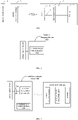
- the conventional wireless charging method is described below with reference to FIG. 1 .
- the wireless charging system includes a power supply device 110, a wireless charging device 120, and a device to be charged 130.
- the wireless charging device 120 may be, for example, a wireless charging base.
- the device to be charged 130 may be, for example, a terminal.
- the wireless charging device 120 may convert the output current of the power supply device 110 into electromagnetic signals (or electromagnetic wave) by the internal wireless transmitter circuit 121.
- the wireless transmitter circuit 121 may convert the output current of the power supply device 110 into alternating current, and convert the alternating current into electromagnetic signals through a transmitting coil or a transmitting antenna (not shown).
- the device to be charged 130 may receive the electromagnetic signals transmitted by the wireless transmitter circuit 121 through the wireless receiver circuit 131 and convert the electromagnetic signals into the output current of the wireless receiver circuit 131.
- the wireless receiver circuit 131 may convert electromagnetic signals transmitted by the wireless transmitter circuit 121 into alternating current through a receiving coil or a receiving antenna (not shown), and perform rectification and/or filtering operations on the alternating current to convert the alternating current into an output voltage and an output current of the wireless receiver circuit 131.
- the wireless charging device 120 and the device to be charged 130 pre-negotiate the transmitting power of the wireless transmitter circuit 121 before wireless charging.
- the output voltage and output current of the wireless receiver circuit 131 are generally 5 V and 1 A.
- the output voltage and output current of the wireless receiver circuit 131 are generally 9 V and 1.2 A.
- the output voltage of the wireless receiver circuit 131 is not suitable for being directly applied to both ends of the battery 133, but needs to be converted by a conversion circuit 132 in the device to be charged 130 to obtain the charging voltage and/or charging current expected by the battery 133 in the device to be charged 130.
- the conversion circuit 132 may be configure to convert the output voltage of the wireless receiver circuit 131, to meet requirements of the charging voltage and/or charging current expected by the battery 133.
- the conversion circuit 132 may refer to a charging management module, for example a charging integrated circuit (IC).
- the conversion circuit 132 is configured to manage the charging voltage and/or charging current of the battery 133 during charging of the battery 133.
- the conversion circuit 132 may have a voltage feedback function, and/or a current feedback function to enable management of the charging voltage and/or charging current of the battery 133.
- the charging process of the battery may include one or more of a trickle charging stage, a constant current charging stage, and a constant voltage charging stage.
- the conversion circuit 132 may utilize the current feedback function to ensure that a current flowing into the battery 133 in the trickle charging stage meets the charging current (such as a first charging current) expected by the battery 133.
- the conversion circuit 132 may utilize a current feedback loop to ensure that the current flowing into the battery 133 in the constant current charging stage meets the charging current (such as a second charging current, which may be greater than the first charging current) expected by the battery 133.
- the conversion circuit 132 may utilize a voltage feedback loop to ensure that a voltage applied to both ends of the battery 133 in the constant voltage charging stage meets the charging voltage expected by the battery 133.
- the conversion circuit 132 may be configured to perform a step-down process on the output voltage of the wireless receiver circuit 131, to enable the charging voltage obtained after the step-down conversion satisfies the requirements of the charging voltage expected by the battery 133.
- the conversion circuit 132 may be configured to perform a boost process on the output voltage of the wireless receiver circuit 131, to enable the charging voltage obtained after the boost conversion satisfies the requirements of the charging voltage expected by the battery 133.
- the wireless receiver circuit 131 outputs a constant voltage of 5V
- the conversion circuit 132 for example, a buck circuit
- the conversion circuit 132 may perform a buck conversion on the output voltage of the wireless receiver circuit 131, such that the charging voltage obtained after the buck conversion meets a requirement of the charging voltage expected by the battery 133.
- the wireless receiver circuit 131 outputs a constant voltage of 5V
- the conversion circuit 132 may perform a boost conversion on the output voltage of the wireless receiver circuit 131, such that the charging voltage obtained after the boost conversion meets a requirement of the charging voltage expected by the battery 133.
- the conventional wireless charging technology is limited to the standard wireless charging mode.
- the wireless charging device is only suitable for the standard power supply device, and only can provide standard wireless charging voltage and current (for example, 5W charging mode in the QI standard) for the device to be charged, making the charging device too long.
- the power supply device has the fast charging function, for example, when the power supply device is a fast charging adapter, since the device to be charged cannot identify the fast charging function, the power supply device still only can provide the standard wireless charging mode for the device to be charged, which cannot fully utilize the fast charging function for wireless charging, resulting in poor user experience.
- embodiments of the present disclosure provide a wireless charging device.
- the wireless charging device When the wireless charging device is not coupled to the device to be charged, the wireless charging device also identifies the type of the power supply device, for example, whether the power supply device is a fast charging power supply device. In this way, when the wireless charging device identifies the power supply device having the fast charging function, the wireless charging device may adopt the fast charging mode to charge the device to be charged.
- FIG. 2 is a block diagram of a wireless charging device 200 according to an embodiment of the present disclosure.
- the wireless charging device 200 includes a communication control module 210.
- the wireless charging device 200 may be coupled to the power supply device, for example, may be coupled to the power supply device via a charging interface.
- the communication control module 210 is configured to control the power supply device to enter a wakeup state when the power supply device is in a sleep state, and to communicate with the power supply device in the wakeup state to determine the type of the power supply device.
- the type of the power supply device includes a fast charging type and a non-fast charging type, a maximum output power of the power supply device of the fast charging type is greater than or equal to a preset value, and a maximum output power of the power supply device of the non-fast charging type is less than the preset value.
- the wireless charging device 200 may be coupled to the power supply device via the charging interface.
- the wireless charging device 200 When the wireless charging device 200 is supplied with power, that is, when there is current flowing in the wireless charging device 200, it may be determined that the charging interface is coupled with the power supply device.
- an output current of the power supply device is relatively small, i.e., less than a present value, i.e., the power supply device is in the sleep state.
- the preset value may be set according to practical use. For example, when the power supply device does not have the load, the output current is typically less than 100mA. Since the current is not stable, and considering fluctuation and error factors, generally, the preset value may be set to be greater than 100mA, for example, may be set to be 300mA.
- the wireless charging device 200 controls the power supply device to quit the sleep state and enter the wakeup state through the communication control module 210, such that the communication control module 210 determines the type of the power supply device, i.e., determines whether the power supply device is a fast charging power supply device or a non-fast charging power supply device.
- the communication control module 210 enables the output current of the power supply device to be greater than or equal to the preset value by increasing the load current, so as to enable the power supply device in the sleep state to enter the wakeup state.
- the wireless charging device 200 may include a load circuit, and the communication control module 210 s coupled to the load circuit.
- the communication control module 210 controls the load circuit to switch off, i.e., controls the power supply device to be not coupled wit the load circuit, the power supply device is in the sleep state.
- the communication control module 210 controls the load circuit to switch on, i.e., controls the power supply device to be coupled with the load circuit, to enable the output current of the power supply device to be greater than or equal to the preset value, the power supply device enters the wakeup state from the sleep state.
- the load circuit may include a resistor, and may further include a switch.
- the communication control module 210 switches on or off connection between the load circuit and the power supply device by controlling the switch.
- a resistance value of the resistor may be set according to practical use, for example, may be 12 ⁇ .
- the communication control module 210 determines the type of the power supply device after waking up the power supply device in the sleep state.
- a communication mode between the wireless charging device and the power supply device is not limited.
- the wireless charging device may be coupled to the power supply device via a communication interface other than the charging interface, and may perform communication with the power supply device via the communication interface.
- the wireless charging device may perform near field communication (NFC) with the power supply device in a wireless manner.
- NFC near field communication
- the wireless charging device may perform communication with the power supply device via the charging interface without setting an additional communication interface.
- the charging interface 210 may be a USB interface or a lightning interface. Assume that the charging interface 210 is the USB interface, the wireless charging device 200 communicate with the power supply device via data wires of the USB cable.
- the communication control module 210 of the wireless charging device 200 queries whether the type of the power supply device is the fast charging power supply device through data wires (D+ and/D- wires) of the USB cable. When receiving a correct response of the power supply device, the communication control module 210 determines that the power supply device is the fast charging power supply device. When receiving an error response or receiving no response, the communication control module 210 determines that the power supply device is the non-fast charging power supply device. In detail, the wireless charging device 200 may send a query message to the power supply device. When the wireless charging device receives a correct reply message sent by the power supply device, the reply message indicates that the power supply device is of the fast charging type.
- D+ and/D- wires data wires
- the correct rely message may be set as "01", and when the reply message of "01" is received, it indicates that the type of the power supply device is the fast charging type. Otherwise, when the wireless charging device does not receive the reply message sent by the power supply device or receives a wrong reply message, the reply message indicates that the power supply device is of the non-fast charging type.
- the correct rely message may be set as "01”, and when the reply message received is not "01", it indicates that the type of the power supply device is the non-fast charging type.
- the charging interface may be a USB interface (such as a USB TYPE-C interface) that supports a power delivery (PD) communication protocol, and the wireless charging device may perform communication with the power supply device based on the PD communication protocol.
- PD power delivery
- the type of the power supply device is not specifically limited in the embodiments of the present disclosure.
- the power supply device may be an adapter, a power bank, a car charger, or a computer.
- the types of the power supply devices includes two classifications, one is the fast charging type corresponding to the first wireless charging mode, in which the maximum output power of the power supply device of the fast charging type is greater than or equal to a preset value, and the other is the non-fast charging type corresponding to the second wireless charging mode in which the maximum output power of the power supply device of the non-fast charging type is less than the preset value.
- the type of the power supply device corresponding to the first wireless charging mode may be a fast charging adapter, which supports the fast charging function
- the type of the power supply device corresponding to the second wireless charging mode may be a standard adapter or a USB interface of the computer, which does not support the fast charging function.
- the output current of the power supply device may be constant direct current, pulsating direct current or alternating current, which is not specifically limited in the embodiments of the present disclosure.
- the wireless charging device 200 controls the output current of the power supply device to be less than the preset value, such that the power supply device quits the wakeup state and re-enters the sleep state, thereby reducing power consumption.
- the wireless charging device 200 may switch off the load circuit, such that the output current of the power supply device reduces to less than the preset value and the power supply device enters the sleep state.
- FIG. 3 illustrates another block diagram of a wireless charging device according to an embodiment of the present disclosure.
- the wireless charging device 200 may further include a charging interface 220, and may further include a wireless transmitter circuit 230.
- the wireless transmitter circuit 230 is configured to, when the power supply device is the fast charging power supply device, transmit an electromagnetic signal in a first wireless charging mode to charge a battery of the device to be charged, or, when the power supply device is the non-fast charging power supply device, transmit an electromagnetic signal in a second wireless charging mode to charge the battery.
- a charging speed of the wireless transmitter circuit charging the battery in the first wireless charging mode is greater than a charging speed of the wireless transmitter circuit charging the battery in the second wireless charging mode.
- the wireless charging device 200 may further provide the type of the power supply device to the device to be charged, such that the device to be charged may enter the corresponding wireless charging mode according to the type of the power supply device. For example, when the power supply device is the fast charging power supply device, the device to be charged enters the first wireless charging mode, and when the power supply device is the normal power supply device, the device to be charges enters the second wireless charging mode.
- both the wireless charging device 200 and the device to be charged may support the first wireless charging mode and the second wireless charging mode, in which the charging speed of the wireless charging device 200 charging the device to be charged in the first wireless charging mode is greater than the charging speed of the wireless charging device charging the device to be charged in the second wireless charging mode.
- the wireless charging device working in the second wireless charging mode it takes less time for the wireless charging device working in the first wireless charging mode to charge the battery with the same capacity in the device to be charged.
- the corresponding second wireless charging mode may be referred to as the normal wireless charging mode.
- the power supply device is the fast charging power supply device, i.e., when the maximum output power of the fast charging power supply device is greater than or equal to the preset value
- the corresponding first wireless charging mode may be referred to as the fast wireless charging mode.
- the wireless charging device 200 further includes a voltage conversion circuit 240.
- the voltage conversion circuit 240 is configured to perform voltage conversion on the current provided to the wireless transmitter circuit 230 when the voltage value of the current provided to the wireless transmitter circuit 230 does not meet a preset condition.
- the current provided to the wireless transmitter circuit 230 may be provided by the power supply device.
- the voltage conversion circuit 240 may be omitted, to simplify the implementation of the wireless charging device.
- the voltage requirement of the wireless transmitter circuit 230 for the input voltage may be set according to practical use, for example, may be set to 10V.
- the voltage value of the current provided to the wireless transmitter circuit 230 not meeting the preset condition may mean that, the voltage value is less than the required voltage the wireless transmitter circuit 230, or the voltage value is greater than the required voltage of the wireless transmitter circuit 230.
- the wireless charging device 200 when the wireless charging device 200 identifies the type of the power supply device as the non-fast charging type, if the wireless charging device 200 still performs the wireless charging in the first charging mode, in which charging mode, the requirement for the input voltage of the wireless transmitter circuit 230 is higher (for example, the required voltage is 10V or 20V), i.e., if the voltage provided to the wireless transmitter circuit 230 cannot reach the voltage requirement of the wireless transmitter circuit 230, i.e., cannot reach the voltage requirement of the device to be charged, the voltage conversion circuit 240 may perform boost process on the input voltage, to enable the boosted voltage to reach the voltage requirement of the wireless transmitter circuit 230.
- the wireless charging device 200 when the wireless charging device 200 identifies the type of the power supply device as the fast charging type, if the wireless charging device 200 still performs wireless charging in the second charging mode, i.e., if the output voltage of the power supply device exceeds the voltage requirement of the wireless transmitter circuit, the voltage conversion circuit 240 may perform step-down process on the input voltage, to enable the stepped-down voltage to reach the voltage requirement of the wireless transmitter circuit 230.
- charging the device to be charged in the first charging mode may still be achieve; or, with the voltage conversion circuit 240, when the power supply device is the fast charging power supply device, charging the device to be charged in the second charging mode may still be achieved, which can improve the charging speed, and achieve the compatibility of the wireless charging device 200.
- the normal wireless charging mode may refer to a wireless charging mode in which the transmitting power (or output power) of the wireless charging device is relatively small and the output power is fixed (usually less than 15 W, and the commonly used transmitting power is 5 W or 10 W), and correspondingly, the maximum output power of the power supply device of the non-fast charging type may be set as the fixed power, or the transmitting power of the power supply device of the non-fast charging type may be set as the fixed power, for example, set to less than 15W, and generally, set as 5W or 10W. In the normal wireless charging mode, it may take several hours to fully charge a larger capacity battery (such as a battery with 3000 mAh).
- a larger capacity battery such as a battery with 3000 mAh
- the fast wireless charging mode may refer to a wireless charging mode in which the transmitting power (or output power) of the wireless charging device is relatively higher and the output power is adjustable (usually greater than 15 W), and correspondingly, the maximum output power of the power supply device of the fast charging type may be set as the higher power value, for example, set to greater than 15W, for example, set as 20W.
- the transmitting power of the power supply device of the fast charging type may be set as adjustable power, or the transmitting power of the power supply device of the fast charging type may be set as fixed power.
- the charging speed of the wireless charging device in the fast wireless charging mode is faster, and the charging time required for fully charging a battery with a same capacity in the fast wireless charging mode may be significantly shortened.
- the fixed output power does not necessarily mean that the output power remains completely unchanged, instead, the fixed output power may vary within a certain range, for example, the output power fluctuates by 0.5 W either way of 10 W
- the wireless charging device 200 in embodiments of the present disclosure may perform wireless communication with the device to be charged. Specifically, after the power supply device is coupled to the wireless charging device 200 of embodiments of the present disclosure, the wireless charging device 200 may identify the type of the power supply device, and the wireless charging device 200 may charge the device to be charged in a corresponding wireless charging mode according to the identified type of the power supply device. For example, when the identified power supply device is the fast charging power supply device, the wireless charging device 200 may charge the device to be charged in the first wireless charging mode; and when the identified power supply device is the normal power supply device, the wireless charging device 200 may charge the device to be charged in the second wireless charging mode.
- the power of the electromagnetic signal transmitted by the wireless charging device 200 through the wireless transmitter circuit 230 matches the charging voltage and/or the charging current present required by the battery in the device to be charged.
- the manner of adjusting the transmitting power of the wireless transmitter circuit 230 is not specifically limited in embodiments of the present disclosure.
- the wireless charging device 200 may communicate with the power supply device, to adjust the output voltage and/or output current of the power supply device, thereby adjusting the transmitting power of the wireless transmitter circuit 230. Adjusting the transmitting power of the wireless transmitter circuit 230 is controlled by the power supply device, which adjusts the transmitting power of the wireless transmitter circuit 230 by changing the output voltage and/or the output current. This way of adjusting the transmitting power is advantageous in that, the power supply device may provide as much power as the wireless charging device needs, thus avoiding waste of power.
- the wireless charging device 200 may actively determine whether there is a need to adjust the output voltage and/or output current of the power supply device. Or, the wireless charging device 200 may act as a bridge of communication between the power supply device and the device to be charged, which is mainly responsible for forwarding messages between the two.
- the communication control module 210 communicates with the device to be charged, to determine whether there is a need to adjust the output voltage and/or output current of the power supply device. When there is a need to adjust the output voltage and/or output current of the power supply device, the communication control module 210 communicates with the power supply device, to instruct the power supply device to adjust the output voltage and/or output current of the power supply device.
- the communication control module 210 in the wireless charging device 200 performs wireless communication with the device to be charged, to obtain adjustment information, in which the adjustment information is configured to instruct adjusting the output voltage and/or output current of the power supply device.
- the communication control module 210 communicates with the power supply device, to send the adjustment information to the power supply device, such that the power supply device adjusts the output voltage and/or output current of the power supply device according to the adjustment information.
- the adjustment information may instruct the power supply device to increase the transmitting power of the wireless transmitter circuit.
- the adjustment information may instruct the power supply device to decrease the transmitting power of the wireless transmitter circuit.
- the power supply device may set a plurality of levels for the transmitting power of the wireless transmitter circuit. Every time when the power supply device receives the adjustment information, it adjusts the transmitting power by one level until the output voltage and/or the output current of the wireless receiver circuit in the device to be charged match the charging stage where the battery presently is.
- the wireless charging device 200 may adjust a power quantity drawn by the wireless transmitter circuit 230 from the maximum output power provided by the power supply device, thereby adjusting the transmitting power of the wireless transmitter circuit 230.
- adjusting the transmitting power of the wireless transmitter circuit 230 is controlled by the wireless charging device 200, and the wireless charging device 200 adjusts the transmitting power of the wireless transmitter circuit 230 immediately once receiving the adjustment information of the device to be charged, which has the advantages of fast adjustment speed and high efficiency.
- the wireless charging device 200 may further perform wireless communication with the device to be charged to adjust the transmitting power of the wireless transmitter circuit 230 according to the requirement of the battery to be charged.
- the output power of the power supply device is fixed, and the transmitting power of the wireless charging device 200 may be adjusted based on adjustment information fed back by the device to be charged.
- the device to be charged may send adjustment information to the wireless charging device 200, to instruct the wireless charging device 200 to adjust the transmitting power of the wireless transmitter circuit.
- the adjustment information may instruct the wireless charging device 200 to increase the transmitting power of the wireless transmitter circuit.
- the adjustment information may instruct the wireless charging device 200 to decrease the transmitting power of the wireless transmitter circuit.
- the wireless charging device 200 may set a plurality of levels for the transmitting power of the wireless transmitter circuit 230. Every time when the wireless charging device 200 receives the adjustment information, it adjusts the transmitting power of the wireless transmitter circuit 230 by one level until the output voltage and/or the output current of the wireless receiver circuit in the device to be charged match the charging stage where the battery presently is.
- the power supply device may be the normal power supply device with the fixed output power
- the wireless charging device 200 does not adjust the power outputted by the power supply device
- the device to be charged is charged with the fixed transmitting power.
- other communication information may be communicated between the wireless charging device 200 and the device to be charged.
- information used for safety protection, abnormality detection or failure processing for example, temperature information of the battery 232, information indicating entering overvoltage protection or overcurrent protection, and power transmission efficiency information (the power transmission efficiency information may be configured to indicate a power transmission efficiency between the wireless transmitter circuit and the wireless receiver circuit), may be communicated between the wireless charging device and the device to be charged.
- the wireless charging device and/or the device to be charged may control the charging loop to enter a protection state, for example, control the charging loop to stop wireless charging.
- the wireless charging device may reduce the transmitting power or stop working.
- the wireless charging device receives the power transmission efficiency information sent by the device to be charged, if the power transmission efficiency is less than a preset threshold, the wireless charging device is controlled to stop working, and the user is informed of the event by, for example, displaying information indicating that the power transmission efficiency is too low through the display, or indicating that the power transmission efficiency is too low through the indicator light, such that the user may adjust the wireless charging environment.
- the wireless communication mode between the wireless charging device 200 and the device to be charged is not limited.
- the wireless charging device and the device to be charged may perform the wireless communication based on Bluetooth, Wi-Fi (wireless fidelity) or backscatter modulation (or power load modulation).
- the charging process of the battery may include at least one of a trickle charging stage, a constant current charging stage, and a constant voltage charging stage.
- the power of the electromagnetic signals transmitted by the wireless charging device matches the charging current corresponding to the trickle charging stage.
- the wireless charging device adjusts the transmitting power of the wireless transmitter circuit, such that the output current of the wireless receiver circuit matches the charging current corresponding to the trickle charging stage (or, such that the output current of the wireless receiver circuit satisfies a requirement of the charging current of the battery during the trickle charging stage).
- the device to be charged may detect the output current of the wireless receiver circuit in real time.
- the device to be charged may communicate with the wireless charging device, such that the wireless charging device adjusts the transmitting power of the wireless transmitter circuit, to enable the output current of the wireless receiver circuit to return back to 1A.
- the power of the electromagnetic signal transmitted by the wireless charging device matches the charging voltage corresponding to the constant voltage charging stage.
- the wireless charging device adjusts the transmitting power of the wireless transmitter circuit, such that the output voltage of the wireless receiver circuit matches the charging voltage corresponding to the constant voltage charging stage (or, such that the output voltage of the wireless receiver circuit satisfies the requirement of the charging voltage of the battery during the constant voltage charging stage).
- the device to be charged may detect the output voltage of the wireless receiver circuit in real time.
- the device to be charged may perform wireless communication with the wireless charging device, so that the wireless charging device adjusts the transmitting power of the wireless transmitter circuit, to make the output voltage of the wireless receiver circuit return to 5V.
- the power of the electromagnetic signal transmitted by the wireless charging device matches the charging current corresponding to the constant current charging stage.
- the wireless charging device adjusts the transmitting power of the wireless transmitter circuit, such that the output current of the wireless receiver circuit matches the charging current corresponding to the constant current charging stage (or, such that the output current of the wireless receiver circuit satisfies the requirement of the charging current of the battery during the constant current charging stage).
- the device to be charged may detect the output current of the wireless receiver circuit in real time.
- the device to be charged may perform wireless communication with the wireless charging device, so that the wireless charging device adjusts the transmitting power of the wireless transmitter circuit, to make the output current of the wireless receiver circuit return to 2A.
- the multi-stage constant current charging may include N constant current stages, where N is an integer no less than 2.
- the first charging stage of the multi-stage constant current charging starts with a predetermined charging current.
- N constant current stages in the multi-stage constant current charging are performed in sequence from the first charging stage to the N th charging stage.
- the peak value or mean value of the current with the pulsating waveform may be decreased.
- the constant current charging is switched from the present constant current stage to the next constant current stage.
- the current change between two adjacent constant current stages may be gradual, or may be in a stepped skip manner.
- the “terminal” may include, but is not limited to a device configured to receive/transmit communication signals via a wired connection (for example, public switched telephone network (PSTN), digital subscriber line (DSL) connection, digital cable connection, direct cable connection and/or another data connection/network) and/or via a wireless interface (for example, cellular network, wireless local area network (WLAN), digital TV network such as digital video broadcasting handheld (DVB-H) network, satellite network, an amplitude modulation-frequency modulation (AM-FM) broadcasting transmitter, and/or a wireless interface of another communication terminal).
- a wired connection for example, public switched telephone network (PSTN), digital subscriber line (DSL) connection, digital cable connection, direct cable connection and/or another data connection/network
- a wireless interface for example, cellular network, wireless local area network (WLAN), digital TV network such as digital video broadcasting handheld (DVB-H) network, satellite network, an amplitude modulation-frequency modulation (AM-FM) broadcasting transmitter, and/or
- the communication terminal configured to communicate via the wireless interface may be referred to as "wireless communication terminal", “wireless terminal” and/or “mobile terminal”.
- a mobile terminal include, but are not limited to a satellite phone or a cell phone, a terminal combining a cell radio phone and a personal communication system (PCS) having capability of data process, fax, and data communication, a personal digital assistant (PDA) including a radio phone, a pager, Internet/Intranet access, a web browser, a note pad & address book, a calendar and/or a global positioning system (GPS) receiver, and a common laptop and/or handheld receiver, or other electronic devices including a radio phone transceiver.
- the device to be charged or terminal used in embodiments of the present disclosure may further include a power bank.
- the power bank may receive charging from the adapter, and store the energy, for providing power for other electronic devices.
- the wireless charging device of embodiments of the present disclosure wakes up the coupled power supply device (the power supply device enters the wakeup state from the sleep state) before charging the device to be charged, so as to communicate with the power supply device to determine whether the type of the coupled power supply device is of the fast charging type.
- the wireless charging device may perform fast charging on the device to be charged, enhancing the charging speed and improving user experience.
- FIG.5 illustrates a schematic flowchart of a wireless charging method 300 according to an embodiment of the present disclosure.
- the method 300 may be executed by the wireless charging device as illustrated in FIGs. 2-4 .
- the method 300 includes followings.
- a wireless charging device controls the power supply device to enter a wakeup state.
- the wireless charging device communicates with the power supply device in the wakeup state, to determine a type of the power supply device.
- the type of the power supply device includes a fast charging type and a non-fast charging type, a maximum output power of the power supply device of the fast charging type is greater than or equal to a preset value, and a maximum output power of the power supply device of the non-fast charging type is less than the preset value.
- the wireless charging device controlling the power supply device to enter the wakeup state includes: when the power supply device is in the sleep state, the wireless charging device controlling an output current of the power supply device to be greater than or equal to a preset value, to enable the power supply device to enter the wakeup state.
- the wireless charging device controlling the output current of the power supply device to be greater than or equal to the preset value includes: when the power supply device is in the sleep state, the wireless charging device controlling the output current of the power supply device to be greater than or equal to the preset value by switching on a load circuit.
- communication between the communication control module and the power supply device is bidirectional communication.
- a charging interface is a universal serial bus USB interface or a lightning interface.
- the charging interface is the USB interface
- the communication control module communicates with the power supply device based on data wires of the USB interface.
- the method further includes: when the power supply device is of the fast charging type, the wireless charging device charging a battery of a device to be charged in a first wireless charging mode; when the power supply device is of the non-fast charging type, the wireless charging device charging the battery of the device to be charged in a second wireless charging mode, wherein a charging speed of the wireless charging device charging the battery in the first wireless charging mode is greater than a charging speed of the wireless charging device charging the battery in the second wireless charging mode.
- the method further includes: when the power supply device is of the non-fast charging type, performing boost process on an output voltage of the wireless charging device, to enable the wireless charging device to transmit an electromagnetic signal in a first wireless charging mode to charge a battery of a device to be charged; or when the power supply device is of the fast charging type, perform step-down process on an output voltage of the wireless charging device, to enable the wireless charging device to transmit an electromagnetic signal in a second wireless charging mode to charge the battery, wherein a charging speed of the wireless charging device charging the battery in the first wireless charging mode is greater than a charging speed of the wireless charging device charging the battery in the second wireless charging mode.
- the first wireless charging mode is a wireless charging mode in which an output power of the wireless transmitter circuit is variable
- the second wireless charging mode is a wireless charging mode in which the output power of the wireless transmitter circuit is fixed.
- a power of the electromagnetic signal transmitted by the wireless charging device matches a charging voltage and/or a charging current present required by the battery.
- the wireless charging device charging the battery of the device to be charged in the first wireless charging mode includes: the wireless charging device performing wireless communication with the device to be charged to determine the charging voltage and/or the charging current presently required by the battery; and the wireless charging device adjusting a transmitting power, such that the power of the electromagnetic signal transmitted by the wireless transmitter circuit matches the charging voltage and/or the charging current presently required by the battery.
- a charging process of the battery includes at least one of a trickle charging state, a constant current charging stage and a constant voltage charging stage.
- a power of the electromagnetic signal transmitted by the wireless charging device matches the charging current corresponding to the constant current charging stage.
- the power of the electromagnetic signal transmitted by the wireless charging device matches the charging voltage corresponding to the constant voltage charging stage.
- the wireless charging device includes the power supply device.
- the power supply device is an adapter, a power bank or a computer.
- the wireless charging device wakes up the coupled power supply device (the power supply device enters the wakeup state from the sleep state) before charging the device to be charged, so as to communicate with the power supply device to determine whether the type of the coupled power supply device is of the fast charging type.
- the wireless charging device may perform fast charging on the device to be charged, enhancing the charging speed and improving user experience.
- sequence number of above processes does not imply execution order of the processes, and the execution order of the processes should be determined according to their functions and internal logic.
- the sequence number should not construct any limitation to the implementation of embodiments of the present disclosure.
- association relation that describes association objects, which means that there may be three kinds of relationships, for example, A and/or B may mean that, A exists separately, A and B exists simultaneously, and B exists separately.
- character "/” herein generally means that the object before the character "/” and the object after the character "/” are associated with an "or” relationship.
- Embodiments of the present disclosure also provide a wireless charging system.
- the wireless charging system 400 may include a wireless charging device 410, a device to be charged 420, and a power supply device 430.
- the wireless charging device 410 may correspond to the wireless charging device 200 in embodiments of the present disclosure.
- the device to be charged 420 and the power supply device 430 may correspond to the device to be charged and the power supply device in the wireless charging method 300 of embodiments of the present disclosure.
- the device to be charged 420 and the power supply device 430 may also correspond to the device to be charged and the power supply device as illustrated in FIGs. 2-4 in embodiment of the present disclosure.
- the system, devices and method disclosed in several embodiments provided by the present disclosure may be realized in any other manner.
- the device embodiments described above may be merely exemplary, for example, the units are just divided according to logic functions. In practical implementation, the units may be divided in other manners, for example, multiple units or components may be combined or integrated into another system, or some features may be omitted or not executed.
- the mutual coupling or direct coupling or communication connection described or discussed may be implemented via some interfaces, and indirect coupling or communication connection between devices or units may be electrical, mechanical or of other forms.
- the units illustrated as separate components may be or not be separated physically, and components described as units may be or not be physical units, i.e., may be located at one place, or may be distributed onto multiple network units. It is possible to select some or all of the units according to actual needs, for realizing the objective of embodiments of the present disclosure
- respective functional units in respective embodiments of the present disclosure may be integrated into one processing unit, or may be present as separate physical entities. It is also possible that two or more than two units are integrated into one unit.
- the functions are realized in form of functional software units and are sold or used as separate products, they may be stored in a computer readable storage medium.
- the parts of the technical solutions or the essential parts of the technical solutions may be embodied in form of software product, which is stored in a storage medium, and includes several instruction used for causing a computer device (for example, a personal computer, a server or a network device) to execute all or part of steps in the methods described in respective embodiments of the present disclosure.
- the above storage medium may be any medium capable of storing program codes, including a USB flash disk, a mobile hard disk, a Read-Only Memory (ROM), a Random Access Memory (RAM), a disc, or a light disk.
Landscapes
- Engineering & Computer Science (AREA)
- Power Engineering (AREA)
- Computer Networks & Wireless Communication (AREA)
- Signal Processing (AREA)
- Charge And Discharge Circuits For Batteries Or The Like (AREA)
- Secondary Cells (AREA)
- Protection Of Static Devices (AREA)
Claims (12)
- Drahtlose Ladevorrichtung (200), umfassend:ein Kommunikationsteuermodul (210), das dafür konfiguriert ist, wenn die drahtlose Ladevorrichtung (200) nicht mit einer zu ladenden Vorrichtung gekoppelt ist, eine Energieversorgungsvorrichtung dazu zu steuern, in einen Aufwachzustand einzutreten, wenn sich die Energieversorgungsvorrichtung in einem Ruhezustand befindet, bevor die zu ladende Vorrichtung geladen wird, um mit der Energieversorgungsvorrichtung in dem Aufwachzustand zu kommunizieren, um einen Typ der Energieversorgungsvorrichtung zu bestimmen,wobei der Typ der Energieversorgungsvorrichtung einen Schnellladetyp und einen Nicht-Schnellladetyp umfasst, eine maximale Ausgangsleistung der Energieversorgungsvorrichtung des Schnellladetyps größer als oder gleich einem voreingestellten Wert ist und eine maximale Ausgangsleistung der Energieversorgungsvorrichtung des Nicht-Schnellladetyps kleiner als der voreingestellte Wert ist,wobei das Kommunikationsteuermodul (210) dafür konfiguriert ist, die Energieversorgungsvorrichtung dazu zu steuern, in den Aufwachzustand einzutreten, wenn sich die Energieversorgungsvorrichtung in dem Ruhezustand befindet, durch:wenn sich die Energieversorgungsvorrichtung in dem Ruhezustand befindet, Steuern eines Ausgangsstroms der Energieversorgungsvorrichtung durch das Kommunikationsteuermodul derart, dass dieser größer als oder gleich einem voreingestellten Wert ist, um die Energieversorgungsvorrichtung in die Lage zu versetzen, in den Aufwachzustand einzutreten,wobei, nachdem die drahtlose Ladevorrichtung (200) den Typ der Energieversorgungsvorrichtung durch das Kommunikationsteuermodul (210) bezieht, da die drahtlose Ladevorrichtung (200) nicht mit der zu ladenden Vorrichtung gekoppelt ist, die drahtlose Ladevorrichtung dafür konfiguriert ist, den Ausgangsstrom der Energieversorgungsvorrichtung so zu steuern, dass er kleiner als der voreingestellte Wert ist, sodass die Energieversorgungsvorrichtung den Aufwachzustand verlässt und wieder in den Ruhezustand eintritt,wobei die drahtlose Ladevorrichtung (200) dafür konfiguriert ist, über eine Ladeschnittstelle mit der Energieversorgungsvorrichtung gekoppelt zu sein,wobei die drahtlose Ladevorrichtung (200) ferner umfasst:einen drahtlosen Übertragungsstromkreis (230), der dafür konfiguriert ist, nachdem die drahtlose Ladevorrichtung (200) den Typ der Energieversorgungsvorrichtung bezieht und wenn die drahtlose Ladevorrichtung (200) mit der zu ladenden Vorrichtung gekoppelt ist, wenn die Energieversorgungsvorrichtung vom Schnellladetyp ist, ein elektromagnetisches Signal in einem ersten drahtlosen Lademodus zu übertragen, um eine Batterie der zu ladenden Vorrichtung zu laden, oder, wenn die Energieversorgungsvorrichtung vom Nicht-Schnellladetyp ist, ein elektromagnetisches Signal in einem zweiten drahtlosen Lademodus zu übertragen, um die Batterie zu laden,wobei eine Ladegeschwindigkeit des drahtlosen Übertragungsstromkreises (230), der die Batterie in dem ersten drahtlosen Lademodus lädt, größer ist als eine Ladegeschwindigkeit des drahtlosen Übertragungsstromkreises (230), der die Batterie in dem zweiten drahtlosen Lademodus lädt.
- Drahtlose Ladevorrichtung (200) nach Anspruch 1, wobei die drahtlose Ladevorrichtung (200) ferner einen Laststromkreis umfasst,
das Kommunikationsteuermodul (210) spezifisch für Folgendes konfiguriert ist:
wenn sich die Energieversorgungsvorrichtung in dem Ruhezustand befindet, Steuern des Ausgangsstroms der Energieversorgungsvorrichtung derart, dass er größer als oder gleich dem voreingestellten Wert ist, durch Anschalten des Laststromkreises. - Drahtlose Ladevorrichtung (200) nach einem der Ansprüche 1 und 2, wobei die Kommunikation zwischen dem Kommunikationsteuermodul (210) und der Energieversorgungsvorrichtung eine bidirektionale Kommunikation ist.
- Drahtlose Ladevorrichtung (200) nach einem der Ansprüche 1 bis 3, wobei die Ladeschnittstelle (220) eine Universal-Serial-Bus-, USB-, Schnittstelle ist.
- Drahtlose Ladevorrichtung (200) nach Anspruch 4, wobei das Kommunikationsteuermodul (210) dafür konfiguriert ist, mit der Energieversorgungsvorrichtung basierend auf Datenleitungen der USB-Schnittstelle zu kommunizieren.
- Drahtlose Ladevorrichtung (200) nach einem der Ansprüche 1 bis 5, wobei die drahtlose Ladevorrichtung (200) ferner einen Spannungswandlungsstromkreis (240) umfasst,
wobei der Spannungswandlungsstromkreis (240) für Folgendes konfiguriert ist:wenn die Energieversorgungsvorrichtung vom Nicht-Schnellladetyp ist, Durchführen eines Erhöhungsprozesses an einer Ausgangsspannung des drahtlosen Übertragungsstromkreises (230), um den drahtlosen Übertragungsstromkreis (230) in die Lage zu versetzen, ein elektromagnetisches Signal in einem ersten drahtlosen Lademodus zu senden, um eine Batterie einer zu ladenden Vorrichtung zu laden, oderwenn die Energieversorgungsvorrichtung vom Schnellladetyp ist, Durchführen eines Abspannprozesses an einer Ausgangsspannung des drahtlosen Übertragungsstromkreises (230), um den drahtlosen Übertragungsstromkreis (230) in die Lage zu versetzen, ein elektromagnetisches Signal in einem zweiten drahtlosen Lademodus zu senden, um die Batterie zu laden. - Drahtlose Ladevorrichtung (200) nach Anspruch 1, wobei der erste drahtlose Lademodus ein drahtloser Lademodus ist, in dem eine Ausgangsleistung des drahtlosen Übertragungsstromkreises (230) variabel ist, und der zweite drahtlose Lademodus ein drahtloser Lademodus ist, in dem die Ausgangsleistung des drahtlosen Übertragungsstromkreises (230) unveränderlich ist.
- Drahtlose Ladevorrichtung (200) nach einem der Ansprüche 1, wobei in dem ersten drahtlosen Lademodus eine Leistung des elektromagnetischen Signals, das von dem drahtlosen Übertragungsstromkreis (230) übertragen wird, einer Ladespannung und/oder einem Ladestrom entspricht, die/der gegenwärtig von der Batterie benötigt wird.
- Drahtlose Ladevorrichtung (200) nach Anspruch 8, das Kommunikationsteuermodul (210) in dem ersten drahtlosen Lademodus spezifisch für Folgendes konfiguriert ist:Durchführen von drahtloser Kommunikation mit der zu ladenden Vorrichtung, um die Ladespannung und/oder den Ladestrom zu bestimmen, die/der gegenwärtig von der Batterie benötigt wird, undJustieren der Übertragungsleistung des drahtlosen Übertragungsstromkreises (230), sodass die Leistung des elektromagnetischen Signals, das von dem drahtlosen Übertragungsstromkreises (230) übertragen wird, der Ladespannung und/oder dem Ladestrom entspricht, die/der gegenwärtig von der Batterie benötigt wird.
- Drahtlose Ladevorrichtung (200) nach einem der Ansprüche 1 bis 9, wobei die drahtlose Ladevorrichtung (200) die Energieversorgungsvorrichtung umfasst.
- Drahtlose Ladevorrichtung (200) nach einem der Ansprüche 1 bis 9, wobei die Energieversorgungsvorrichtung ein Adapter, eine Powerbank oder ein Computer ist.
- Drahtloses Ladeverfahren, umfassend:wenn eine drahtlose Ladevorrichtung (200) nicht mit einer zu ladenden Vorrichtung gekoppelt ist,Steuern einer Energieversorgungsvorrichtung durch die drahtlose Ladevorrichtung (200), wenn sich die Energieversorgungsvorrichtung in einem Ruhemodus befindet, dazu, in einen Aufwach-Zustand einzutreten, bevor die zu ladende Vorrichtung geladen wird, sodasssie in dem Aufwachzustand mit der Energieversorgungsvorrichtung kommuniziert, um einen Typ der Energieversorgungsvorrichtung zu bestimmen, wobei der Typ der Energieversorgungsvorrichtung einen Schnellladetyp und einen Nicht-Schnellladetyp umfasst, eine maximale Ausgangsleistung der Energieversorgungsvorrichtung des Schnellladetyps größer als oder gleich einem voreingestellten Wert ist und eine maximale Ausgangsleistung der Energieversorgungsvorrichtung des Nicht-Schnellladetyps kleiner als der voreingestellte Wert ist,wobei, wenn sich die Energieversorgungsvorrichtung in dem Ruhezustand befindet, das Steuern der Energieversorgungsvorrichtung durch die drahtlose Ladevorrichtung (200) dazu, in den Aufwachzustand einzutreten, Folgendes umfasst:wenn sich die Energieversorgungsvorrichtung in dem Ruhezustand befindet, Steuern eines Ausgangsstroms der Energieversorgungsvorrichtung durch die drahtlose Ladevorrichtung (200) so, dass dieser größer als oder gleich einem voreingestellten Wert ist, um die Energieversorgungsvorrichtung in die Lage zu versetzen, in den Aufwachzustand einzutreten,wobei, nachdem die drahtlose Ladevorrichtung (200) den Typ der Energieversorgungsvorrichtung über das Kommunikationsteuermodul (210) bezieht, da die drahtlose Ladevorrichtung (200) nicht mit der zu ladenden Vorrichtung gekoppelt ist, die drahtlose Ladevorrichtung den Ausgangsstrom der Energieversorgungsvorrichtung so steuert, dass er kleiner als der voreingestellte Wert ist, sodass die Energieversorgungsvorrichtung den Aufwachzustand verlässt und wieder in den Ruhezustand eintritt,wobei die drahtlose Ladevorrichtung (200) über eine Ladeschnittstelle mit der Energieversorgungsvorrichtung gekoppelt ist,wobei das drahtlose Ladeverfahren ferner umfasst:nachdem die drahtlose Ladevorrichtung (200) den Typ der Energieversorgungsvorrichtung bezieht und wenn die drahtlose Ladevorrichtung (200) mit der zu ladenden Vorrichtung gekoppelt ist,wenn die Energieversorgungsvorrichtung vom Schnellladetyp ist, Laden einer Batterie einer zu ladenden Vorrichtung in einem ersten drahtlosen Lademodus durch die drahtlose Ladevorrichtung,wenn die Energieversorgungsvorrichtung vom Nicht-Schnellladetyp ist, Laden der Batterie der zu ladenden Vorrichtung in einem zweiten drahtlosen Lademodus durch die drahtlose Ladevorrichtung,wobei eine Ladegeschwindigkeit der drahtlosen Ladevorrichtung, die die Batterie in dem ersten drahtlosen Lademodus lädt, größer ist als eine Ladegeschwindigkeit der drahtlosen Ladevorrichtung, die die Batterie in dem zweiten drahtlosen Lademodus lädt.
Applications Claiming Priority (2)
| Application Number | Priority Date | Filing Date | Title |
|---|---|---|---|
| PCT/CN2017/079784 WO2018184230A1 (zh) | 2017-04-07 | 2017-04-07 | 无线充电系统、装置、方法及待充电设备 |
| PCT/CN2018/081971 WO2018184577A1 (zh) | 2017-04-07 | 2018-04-04 | 无线充电装置和无线充电方法 |
Publications (3)
| Publication Number | Publication Date |
|---|---|
| EP3609049A1 EP3609049A1 (de) | 2020-02-12 |
| EP3609049A4 EP3609049A4 (de) | 2020-04-08 |
| EP3609049B1 true EP3609049B1 (de) | 2022-12-28 |
Family
ID=63711967
Family Applications (8)
| Application Number | Title | Priority Date | Filing Date |
|---|---|---|---|
| EP17904556.2A Withdrawn EP3462564A4 (de) | 2017-04-07 | 2017-04-07 | Drahtloses ladesystem, vorrichtung und verfahren sowie aufzuladende vorrichtung |
| EP18781141.9A Active EP3609039B1 (de) | 2017-04-07 | 2018-02-13 | Vorrichtung und verfahren zum drahtlosen aufladen |
| EP18781580.8A Active EP3595125B1 (de) | 2017-04-07 | 2018-02-13 | System und verfahren zum drahtlosen laden sowie aufzuladende vorrichtung |
| EP18781860.4A Active EP3609045B1 (de) | 2017-04-07 | 2018-02-13 | System und verfahren zum drahtlosen laden und aufzuladende vorrichtung |
| EP18781325.8A Active EP3609041B1 (de) | 2017-04-07 | 2018-04-04 | Drahtloses ladeverfahren, vorrichtung und system |
| EP18780574.2A Active EP3609037B1 (de) | 2017-04-07 | 2018-04-04 | Vorrichtung unter ladung, drahtlose ladevorrichtung und steuerungsverfahren dafür |
| EP18781530.3A Active EP3609043B1 (de) | 2017-04-07 | 2018-04-04 | Drahtloses ladeverfahren, vorrichtung, system und aufzuladende vorrichtung |
| EP18780781.3A Active EP3609049B1 (de) | 2017-04-07 | 2018-04-04 | Drahtlose ladevorrichtung und drahtloses ladeverfahren |
Family Applications Before (7)
| Application Number | Title | Priority Date | Filing Date |
|---|---|---|---|
| EP17904556.2A Withdrawn EP3462564A4 (de) | 2017-04-07 | 2017-04-07 | Drahtloses ladesystem, vorrichtung und verfahren sowie aufzuladende vorrichtung |
| EP18781141.9A Active EP3609039B1 (de) | 2017-04-07 | 2018-02-13 | Vorrichtung und verfahren zum drahtlosen aufladen |
| EP18781580.8A Active EP3595125B1 (de) | 2017-04-07 | 2018-02-13 | System und verfahren zum drahtlosen laden sowie aufzuladende vorrichtung |
| EP18781860.4A Active EP3609045B1 (de) | 2017-04-07 | 2018-02-13 | System und verfahren zum drahtlosen laden und aufzuladende vorrichtung |
| EP18781325.8A Active EP3609041B1 (de) | 2017-04-07 | 2018-04-04 | Drahtloses ladeverfahren, vorrichtung und system |
| EP18780574.2A Active EP3609037B1 (de) | 2017-04-07 | 2018-04-04 | Vorrichtung unter ladung, drahtlose ladevorrichtung und steuerungsverfahren dafür |
| EP18781530.3A Active EP3609043B1 (de) | 2017-04-07 | 2018-04-04 | Drahtloses ladeverfahren, vorrichtung, system und aufzuladende vorrichtung |
Country Status (6)
| Country | Link |
|---|---|
| US (8) | US10998751B2 (de) |
| EP (8) | EP3462564A4 (de) |
| JP (5) | JP6812537B2 (de) |
| KR (5) | KR102328496B1 (de) |
| CN (9) | CN109314396B (de) |
| WO (8) | WO2018184230A1 (de) |
Families Citing this family (59)
| Publication number | Priority date | Publication date | Assignee | Title |
|---|---|---|---|---|
| KR102222153B1 (ko) | 2017-04-07 | 2021-03-03 | 광동 오포 모바일 텔레커뮤니케이션즈 코포레이션 리미티드 | 무선 충전 장치, 무선 충전 방법, 및 충전 대기 설비 |
| WO2018184230A1 (zh) * | 2017-04-07 | 2018-10-11 | Oppo广东移动通信有限公司 | 无线充电系统、装置、方法及待充电设备 |
| BR112019018588B1 (pt) * | 2017-04-07 | 2023-12-26 | Guangdong Oppo Mobile Telecommunications Corp., Ltd | Dispositivo a ser carregado, sistema de carregamento sem fio e método de carregamento sem fio |
| CN108539832A (zh) * | 2018-03-16 | 2018-09-14 | 维沃移动通信有限公司 | 无线充电接收端设备、无线充电方法、系统及终端设备 |
| AR114789A1 (es) * | 2018-04-18 | 2020-10-14 | Hoffmann La Roche | Anticuerpos anti-hla-g y uso de los mismos |
| CN111095720B (zh) * | 2018-05-31 | 2023-06-20 | Oppo广东移动通信有限公司 | 充电方法和充电装置 |
| WO2020124582A1 (zh) * | 2018-12-21 | 2020-06-25 | Oppo广东移动通信有限公司 | 接收装置和无线充电方法 |
| WO2020124571A1 (zh) | 2018-12-21 | 2020-06-25 | Oppo广东移动通信有限公司 | 充电装置、待充电设备、充电方法及计算机存储介质 |
| WO2020133081A1 (zh) * | 2018-12-27 | 2020-07-02 | Oppo广东移动通信有限公司 | 充电方法和装置、待充电设备、存储介质及芯片系统 |
| CN113412567B (zh) | 2019-01-18 | 2024-08-23 | Oppo广东移动通信有限公司 | 无线充电控制方法和充电控制装置 |
| US11532950B2 (en) * | 2019-05-08 | 2022-12-20 | Western Digital Technologies, Inc. | Systems and methods for wireless charging and wireless data transfer for multiple devices |
| US11581759B2 (en) * | 2019-05-14 | 2023-02-14 | Canon Kabushiki Kaisha | Power reception apparatus, control method, and storage medium |
| CN112186820A (zh) * | 2019-07-02 | 2021-01-05 | 台达电子工业股份有限公司 | 充电器及充电方法 |
| CN112242725B (zh) * | 2019-07-19 | 2022-06-24 | Oppo广东移动通信有限公司 | 无线充电装置、方法及系统 |
| CN112311024A (zh) * | 2019-07-25 | 2021-02-02 | Oppo广东移动通信有限公司 | 待充电设备、无线充电方法及系统 |
| CN112332501B (zh) * | 2019-07-30 | 2022-11-15 | Oppo广东移动通信有限公司 | 无线充电方法和待充电设备 |
| CN110402002B (zh) | 2019-07-31 | 2024-06-04 | 北京小米移动软件有限公司 | 一种开关设备 |
| CN114072980A (zh) * | 2019-08-05 | 2022-02-18 | Oppo广东移动通信有限公司 | 待充电设备 |
| CN111049208A (zh) * | 2019-09-03 | 2020-04-21 | 华乙半导体(深圳)有限公司 | 一种充电方法及电源适配器 |
| JP7321850B2 (ja) * | 2019-09-09 | 2023-08-07 | 株式会社マキタ | 充電器および充電システム |
| CN110635546B (zh) * | 2019-09-18 | 2021-11-30 | 华为数字能源技术有限公司 | 一种无线充电的电子设备、方法及系统 |
| CN110571950A (zh) * | 2019-09-29 | 2019-12-13 | 江西联智集成电路有限公司 | 无线充电设备接收器及无线充电设备检测系统 |
| CN112671052A (zh) * | 2019-10-16 | 2021-04-16 | Oppo广东移动通信有限公司 | 待充电设备及充电方法 |
| CN110649688B (zh) * | 2019-10-21 | 2023-03-14 | 广西电网有限责任公司电力科学研究院 | 一种基于电池温度检测的无线充电控制系统及方法 |
| CN112803610B (zh) * | 2019-11-14 | 2024-07-09 | Oppo广东移动通信有限公司 | 待充电设备、系统以及无线充电方法、存储介质 |
| EP4060852A4 (de) * | 2019-11-14 | 2022-12-21 | Guangdong Oppo Mobile Telecommunications Corp., Ltd. | Elektronische vorrichtung und drahtloses ladegerät, system und verfahren |
| EP4024663A4 (de) * | 2019-11-14 | 2022-11-09 | Guangdong Oppo Mobile Telecommunications Corp., Ltd. | Drahtloses ladegerät, zu ladende vorrichtung, ladesystem und -verfahren und speichermedium |
| CN111049371A (zh) * | 2019-12-16 | 2020-04-21 | 上海南芯半导体科技有限公司 | 一种中等功率低成本的电荷泵充电方法 |
| US11923715B2 (en) * | 2019-12-20 | 2024-03-05 | Qualcomm Incorporated | Adaptive multi-mode charging |
| CN111130183A (zh) * | 2020-01-14 | 2020-05-08 | 北京小米移动软件有限公司 | 无线充电方法和装置、无线充电设备、电子设备 |
| FR3107791B1 (fr) | 2020-03-02 | 2023-03-24 | Radiall Sa | Ensemble de transfert d’énergie électrique sans fil et sans contact comprenant un système amélioré de régulation de l’énergie transférée. |
| US11631999B2 (en) * | 2020-03-06 | 2023-04-18 | Witricity Corporation | Active rectification in wireless power systems |
| JP7437631B2 (ja) * | 2020-03-31 | 2024-02-26 | パナソニックIpマネジメント株式会社 | 通信制御装置、通信制御システム、および、通信制御方法 |
| US11145908B1 (en) | 2020-04-01 | 2021-10-12 | Sensata Technologies, Inc. | Listening only wireless network controller in a wireless battery management system |
| CN111439141A (zh) * | 2020-04-09 | 2020-07-24 | 西交利物浦大学 | 无线充电控制系统及装置 |
| US11588334B2 (en) | 2020-06-02 | 2023-02-21 | Inventus Power, Inc. | Broadcast of discharge current based on state-of-health imbalance between battery packs |
| US11509144B2 (en) | 2020-06-02 | 2022-11-22 | Inventus Power, Inc. | Large-format battery management system with in-rush current protection for master-slave battery packs |
| US11594892B2 (en) | 2020-06-02 | 2023-02-28 | Inventus Power, Inc. | Battery pack with series or parallel identification signal |
| US11489343B2 (en) | 2020-06-02 | 2022-11-01 | Inventus Power, Inc. | Hardware short circuit protection in a large battery pack |
| US11476677B2 (en) | 2020-06-02 | 2022-10-18 | Inventus Power, Inc. | Battery pack charge cell balancing |
| US11552479B2 (en) | 2020-06-02 | 2023-01-10 | Inventus Power, Inc. | Battery charge balancing circuit for series connections |
| US11245268B1 (en) | 2020-07-24 | 2022-02-08 | Inventus Power, Inc. | Mode-based disabling of communiction bus of a battery management system |
| EP4158718A4 (de) | 2020-06-02 | 2024-03-13 | Inventus Power, Inc. | Grossformatiges batterieverwaltungssystem |
| CN111711254B (zh) * | 2020-08-06 | 2020-11-24 | 苏州明纬科技有限公司 | 通用型充电装置及其充电方法 |
| KR102418987B1 (ko) * | 2020-08-11 | 2022-07-11 | (주)화인파워엑스 | 무선 충전 디바이스 |
| CN112117833A (zh) * | 2020-09-01 | 2020-12-22 | 珠海格力电器股份有限公司 | 温控器充电装置和温控器设备 |
| CN112290611A (zh) * | 2020-09-17 | 2021-01-29 | 安克创新科技股份有限公司 | 用于无线充电的系统 |
| CN112701802A (zh) * | 2020-11-19 | 2021-04-23 | 国网浙江省电力有限公司宁波供电公司 | 一种用于机器人的无线充电系统与方法 |
| JP7394888B2 (ja) * | 2021-01-28 | 2023-12-08 | 寧徳時代新能源科技股▲分▼有限公司 | 充電方法及び電力変換装置 |
| TWI783372B (zh) * | 2021-02-08 | 2022-11-11 | 鄭佳吟 | 具有鑲崁功能的無線充電裝置 |
| CN115117946A (zh) | 2021-03-19 | 2022-09-27 | 北京小米移动软件有限公司 | 充电控制方法、充电控制装置、电子设备及存储介质 |
| CN113098143A (zh) * | 2021-03-30 | 2021-07-09 | 北京小米移动软件有限公司 | 电子设备的充电系统、无线充电端、终端及充电方法 |
| CN115347624A (zh) * | 2021-05-13 | 2022-11-15 | 北京小米移动软件有限公司 | Tws耳机充电方法及装置、tws耳机及充电盒、存储介质 |
| CN114024375B (zh) * | 2021-11-25 | 2024-02-13 | 桔充充(杭州)新能源有限公司 | 一种二轮电动车的无线充电系统的故障自保护电路及方法 |
| CN114204630A (zh) * | 2021-11-30 | 2022-03-18 | 联想(北京)有限公司 | 控制方法、电子设备及书写交互装置 |
| DE102022207058A1 (de) * | 2022-07-11 | 2024-01-11 | Robert Bosch Gesellschaft mit beschränkter Haftung | Schnittstellenmodul zum Laden und Entladen eines elektrochemischen Energiespeichers |
| CN117526471A (zh) * | 2022-07-28 | 2024-02-06 | 北京小米移动软件有限公司 | 应用于穿戴设备的无线充电电路及穿戴设备 |
| CN116707154A (zh) * | 2022-09-29 | 2023-09-05 | 荣耀终端有限公司 | 无线电能接收电路及电子设备 |
| TWI846562B (zh) * | 2023-08-11 | 2024-06-21 | 台達電子工業股份有限公司 | 無線充電控制方法及其適用的無線充電系統 |
Family Cites Families (315)
| Publication number | Priority date | Publication date | Assignee | Title |
|---|---|---|---|---|
| US3694668A (en) * | 1970-01-02 | 1972-09-26 | Bunker Ramo | Track and hold system |
| US4641089A (en) * | 1983-04-27 | 1987-02-03 | Hal A. Huggins | Ammeter apparatus and method for capturing current readings |
| US5187615A (en) * | 1988-03-30 | 1993-02-16 | Hitachi, Ltd. | Data separator and signal processing circuit |
| US5057793A (en) * | 1989-11-13 | 1991-10-15 | Cowley Nicholas P | Frequency synthesizer PLL having digital and analog phase detectors |
| JPH03189569A (ja) * | 1989-12-20 | 1991-08-19 | Toshiba Corp | 電圧測定装置 |
| EP0840457A3 (de) * | 1990-10-22 | 1999-08-25 | NEC Corporation | Frequenzsynthetisierer mit PLL, der einen Frequenzwechsel des Ausgangs mit hoher Geschwindigkeit ermöglicht |
| JP3620118B2 (ja) * | 1995-10-24 | 2005-02-16 | 松下電器産業株式会社 | 定電流・定電圧充電装置 |
| JP3439013B2 (ja) | 1996-02-29 | 2003-08-25 | 三洋電機株式会社 | 二次電池のパルス充電方法 |
| JP3595646B2 (ja) * | 1997-03-19 | 2004-12-02 | 株式会社カージオペーシングリサーチ・ラボラトリー | 生体植え込み装置 |
| US6208115B1 (en) | 1997-06-16 | 2001-03-27 | Yehuda Binder | Battery substitute pack |
| JP2000333377A (ja) | 1999-05-21 | 2000-11-30 | Sony Computer Entertainment Inc | エンタテインメントシステムおよび充電システム |
| CN2464002Y (zh) | 2000-12-16 | 2001-12-05 | 蒋冠珞 | 自生反向脉冲的快速充电机 |
| US20120181973A1 (en) * | 2003-08-29 | 2012-07-19 | Robert Lyden | Solar array resembling natural foliage including means for wireless transmission of electric power |
| US20060103355A1 (en) * | 2004-11-16 | 2006-05-18 | Joseph Patino | Method and system for selectively charging a battery |
| US9167471B2 (en) * | 2009-05-07 | 2015-10-20 | Jasper Technologies, Inc. | System and method for responding to aggressive behavior associated with wireless devices |
| KR100853889B1 (ko) * | 2005-07-29 | 2008-08-25 | 엘에스전선 주식회사 | 무 접점 충전 배터리 및 충전기, 이들을 포함하는 배터리충전 세트, 및 충전제어 방법 |
| WO2007013726A1 (en) * | 2005-07-29 | 2007-02-01 | Ls Cable Ltd. | Contact-less chargeable battery and charging device, battery charging set, and charging control method thereof |
| KR100792311B1 (ko) * | 2005-07-30 | 2008-01-07 | 엘에스전선 주식회사 | 충전전력 공급장치, 충전 장치, 배터리 장치, 무접점 충전 시스템 및 무접점 충전 방법 |
| EP1749607B1 (de) * | 2005-08-01 | 2012-03-14 | Agie Charmilles SA | Verfahren und Generator für Funkenerosionsbearbeitung |
| JP4890837B2 (ja) * | 2005-11-07 | 2012-03-07 | ローム株式会社 | 電源装置 |
| EP1960048B1 (de) * | 2005-12-07 | 2010-08-04 | Boston Scientific Neuromodulation Corporation | Batterieschutz- und null-volt-batterie-wiederaufladungssystem für eine implantierbare medizinische vorrichtung |
| CA2632385C (en) * | 2005-12-20 | 2015-02-24 | Tir Technology Lp | Method and apparatus for controlling current supplied to electronic devices |
| JP5020530B2 (ja) * | 2006-04-14 | 2012-09-05 | パナソニック株式会社 | 充電方法ならびに電池パックおよびその充電器 |
| US8296587B2 (en) * | 2006-08-30 | 2012-10-23 | Green Plug, Inc. | Powering an electrical device through a legacy adapter capable of digital communication |
| JP4311687B2 (ja) * | 2006-10-06 | 2009-08-12 | 日本テキサス・インスツルメンツ株式会社 | 電源回路およびバッテリ装置 |
| KR100896104B1 (ko) * | 2007-04-25 | 2009-05-07 | 엘에스전선 주식회사 | 부하변조 기능을 갖는 무접점 충전 배터리 및 이를 구비한배터리 충전 세트 |
| CN101330229A (zh) * | 2007-06-21 | 2008-12-24 | 北京市北邮信息科技发展有限责任公司 | 一种非接触式电能传输装置 |
| GB2451470B (en) * | 2007-07-31 | 2011-11-23 | Wolfson Microelectronics Plc | DC-TO-DC converter |
| US8461817B2 (en) * | 2007-09-11 | 2013-06-11 | Powercast Corporation | Method and apparatus for providing wireless power to a load device |
| US8245067B2 (en) * | 2007-11-30 | 2012-08-14 | Agere Systems Inc. | Power sharing among portable electronic devices |
| WO2009069844A1 (en) * | 2007-11-30 | 2009-06-04 | Chun-Kil Jung | Multiple non-contact charging system of wireless power transmision and control method thereof |
| CN101232196B (zh) * | 2008-02-02 | 2011-04-06 | 中兴通讯股份有限公司 | 一种usb充电座中充电模式的控制电路及其方法 |
| KR100976161B1 (ko) * | 2008-02-20 | 2010-08-16 | 정춘길 | 무접점충전시스템 및 그의 충전제어방법 |
| US20090237029A1 (en) * | 2008-03-24 | 2009-09-24 | Spx Corporation | Inductive battery charger for service equipment |
| JP4987775B2 (ja) * | 2008-03-27 | 2012-07-25 | 株式会社東芝 | 無線被給電端末、システムおよび方法 |
| JP2009273327A (ja) * | 2008-05-10 | 2009-11-19 | Sanyo Electric Co Ltd | 電池内蔵機器と充電台 |
| US8527688B2 (en) * | 2008-09-26 | 2013-09-03 | Palm, Inc. | Extending device functionality amongst inductively linked devices |
| US8234509B2 (en) * | 2008-09-26 | 2012-07-31 | Hewlett-Packard Development Company, L.P. | Portable power supply device for mobile computing devices |
| JP5316541B2 (ja) | 2008-09-26 | 2013-10-16 | 株式会社村田製作所 | 無接点充電システム |
| US8947042B2 (en) | 2008-11-13 | 2015-02-03 | Qualcomm Incorporated | Wireless power and data transfer for electronic devices |
| US8497658B2 (en) * | 2009-01-22 | 2013-07-30 | Qualcomm Incorporated | Adaptive power control for wireless charging of devices |
| EP2416470B1 (de) * | 2009-03-30 | 2019-11-13 | Fujitsu Limited | Drahtloses stromversorgungssystem, drahtlose stromübertragungseinrichtung und drahtlose stromempfangseinrichtung |
| JP2011034306A (ja) * | 2009-07-31 | 2011-02-17 | Toshiba Corp | 情報処理装置及び給電制御方法 |
| US8120412B2 (en) * | 2009-08-07 | 2012-02-21 | Freescale Semiconductor, Inc. | Voltage boosting system with slew rate control and method thereof |
| US8928284B2 (en) * | 2009-09-10 | 2015-01-06 | Qualcomm Incorporated | Variable wireless power transmission |
| US8390249B2 (en) | 2009-11-30 | 2013-03-05 | Broadcom Corporation | Battery with integrated wireless power receiver and/or RFID |
| US9094054B2 (en) * | 2009-11-30 | 2015-07-28 | Broadcom Corporation | IC controlled wireless power operation and applications thereof including control channel communication configuration |
| JP5550097B2 (ja) | 2009-12-02 | 2014-07-16 | Necカシオモバイルコミュニケーションズ株式会社 | 無接点充電装置及び電子機器並びにプログラム |
| KR101097262B1 (ko) | 2009-12-28 | 2011-12-21 | 삼성에스디아이 주식회사 | 배터리 팩, 이의 충전방법 |
| WO2011084942A2 (en) | 2010-01-05 | 2011-07-14 | Access Business Group International Llc | Integrated wireless power system |
| WO2011086899A1 (ja) * | 2010-01-13 | 2011-07-21 | パナソニック株式会社 | 電力供給装置および車両充電システム |
| JP2011151891A (ja) * | 2010-01-19 | 2011-08-04 | Sony Corp | 二次電池の充電方法および充電装置 |
| JP2011152018A (ja) * | 2010-01-25 | 2011-08-04 | Sony Corp | ワイヤレス蓄電システムおよびワイヤレス給電システム |
| JP5198489B2 (ja) * | 2010-01-28 | 2013-05-15 | 株式会社エヌ・ティ・ティ・ドコモ | 充電回路、移動機及び充電方法 |
| US9561730B2 (en) * | 2010-04-08 | 2017-02-07 | Qualcomm Incorporated | Wireless power transmission in electric vehicles |
| TWI406471B (zh) * | 2010-05-14 | 2013-08-21 | 崇越科技股份有限公司 | 充電系統及其充電方法 |
| US8890470B2 (en) * | 2010-06-11 | 2014-11-18 | Mojo Mobility, Inc. | System for wireless power transfer that supports interoperability, and multi-pole magnets for use therewith |
| KR101682386B1 (ko) * | 2010-06-29 | 2016-12-12 | 삼성전자 주식회사 | 휴대용 충전 장치 및 그의 충전 방법 및 충전 시스템 |
| JP2012016125A (ja) * | 2010-06-30 | 2012-01-19 | Panasonic Electric Works Co Ltd | 非接触給電システム及び非接触給電システムの金属異物検出装置 |
| SG189531A1 (en) | 2010-11-03 | 2013-05-31 | Xped Holdings Pty Ltd | Wireless device detection and communication apparatus and system |
| CN102013717B (zh) * | 2010-12-03 | 2013-01-16 | 清华大学 | 植入式医疗仪器用具有对位自动提示功能的无线充电方法 |
| KR20120068566A (ko) * | 2010-12-17 | 2012-06-27 | 콘티넨탈 오토모티브 시스템 주식회사 | 무선 충전 방법 및 시스템 |
| US9178369B2 (en) * | 2011-01-18 | 2015-11-03 | Mojo Mobility, Inc. | Systems and methods for providing positioning freedom, and support of different voltages, protocols, and power levels in a wireless power system |
| US20130285605A1 (en) * | 2011-01-18 | 2013-10-31 | Mojo Mobility, Inc. | Systems and methods for wireless power transfer |
| US10141770B2 (en) * | 2011-01-18 | 2018-11-27 | Mojo Mobility, Inc. | Powering and/or charging with a plurality of protocols |
| US9356659B2 (en) * | 2011-01-18 | 2016-05-31 | Mojo Mobility, Inc. | Chargers and methods for wireless power transfer |
| US9496732B2 (en) * | 2011-01-18 | 2016-11-15 | Mojo Mobility, Inc. | Systems and methods for wireless power transfer |
| US20120194124A1 (en) | 2011-01-31 | 2012-08-02 | Nokia Corporation | Wireless Battery Charging System |
| JP5713714B2 (ja) * | 2011-02-10 | 2015-05-07 | キヤノン株式会社 | 給電装置及び制御方法 |
| US20120223590A1 (en) * | 2011-03-02 | 2012-09-06 | Qualcommm Incorporated | Reducing heat dissipation in a wireless power receiver |
| KR101267076B1 (ko) * | 2011-03-24 | 2013-05-24 | 주식회사 한림포스텍 | 무선 전력 전송 어셈블리에서의 전력 제어 방법 및 무선 전력 전송 어셈블리 |
| US9444247B2 (en) * | 2011-05-17 | 2016-09-13 | Samsung Electronics Co., Ltd. | Apparatus and method of protecting power receiver of wireless power transmission system |
| US9735623B2 (en) * | 2011-05-17 | 2017-08-15 | Samsung Electronics Co., Ltd. | Power transmitting method and power transmitter for communication with power receiver |
| JP2012239814A (ja) | 2011-05-24 | 2012-12-10 | Fujifilm Corp | 放射線撮影装置 |
| JP2012249410A (ja) * | 2011-05-27 | 2012-12-13 | Sharp Corp | 電気自動車充電用の充電器及び充電装置 |
| KR102012684B1 (ko) | 2011-05-31 | 2019-08-26 | 삼성전자주식회사 | 무선 전력을 이용한 통신 장치 및 방법 |
| JP5767873B2 (ja) | 2011-06-28 | 2015-08-26 | 株式会社東芝 | 蓄電装置および蓄電システム |
| JP5505375B2 (ja) | 2011-06-29 | 2014-05-28 | 株式会社豊田自動織機 | セルバランス制御装置及びセルバランス制御方法 |
| US9379571B2 (en) * | 2011-07-11 | 2016-06-28 | Delphi Technologies, Inc. | Electrical charging system having energy coupling arrangement for wireless energy transmission therebetween |
| US20130026981A1 (en) * | 2011-07-28 | 2013-01-31 | Broadcom Corporation | Dual mode wireless power |
| JP5893285B2 (ja) | 2011-08-04 | 2016-03-23 | キヤノン株式会社 | 給電装置及びプログラム |
| KR101580342B1 (ko) * | 2011-08-29 | 2015-12-24 | 삼성전기주식회사 | 무선 전력 전송 시스템 및 그의 제어방법 |
| EP2579522B1 (de) * | 2011-10-05 | 2018-05-30 | BlackBerry Limited | Drahtloses Stromversorgung Aufladen und Kommunizieren mit drahtlosen Kommunikationsvorrichtungen in einem Kommunikationssystem |
| US10285241B2 (en) * | 2011-10-06 | 2019-05-07 | A9.Com, Inc. | Wireless lighting device with charging port |
| JP2013085386A (ja) * | 2011-10-11 | 2013-05-09 | Panasonic Corp | 蓄電池制御装置、蓄電池制御方法、電力貯蔵システム及び電気自動車の駆動システム |
| KR101818773B1 (ko) | 2011-10-24 | 2018-02-22 | 삼성전자주식회사 | 공진 방식 무선 충전 시스템용 수신 전력 변환 장치 |
| KR101338732B1 (ko) | 2011-11-10 | 2013-12-06 | 엘지이노텍 주식회사 | 무선전력 송신장치, 무선전력 수신장치, 무선전력 전송 방법, 무선전력 수신 방법, 정보 전송 방법 및 정보 수신 방법 |
| JP2013115859A (ja) * | 2011-11-25 | 2013-06-10 | Hitachi Maxell Ltd | ワイヤレス電力伝送装置 |
| JP6045141B2 (ja) * | 2011-12-05 | 2016-12-14 | キヤノン株式会社 | 電子機器及びプログラム |
| US8928182B2 (en) * | 2011-12-16 | 2015-01-06 | Tdk Corporation | Wireless power feeder and wireless power transmission system |
| CN102522799A (zh) | 2011-12-30 | 2012-06-27 | 成都林海电子有限责任公司 | 一种移动终端电源 |
| JP2015510749A (ja) * | 2012-01-23 | 2015-04-09 | ユタ ステート ユニバーシティ | 無線電力伝送用デュアルサイド制御 |
| US9362774B2 (en) * | 2012-01-27 | 2016-06-07 | Medtronic, Inc. | Battery charging top-off |
| WO2013111469A1 (ja) * | 2012-01-27 | 2013-08-01 | ソニー株式会社 | 電子機器および給電システム |
| JP5880122B2 (ja) * | 2012-02-21 | 2016-03-08 | 株式会社豊田自動織機 | 非接触電力伝送装置 |
| KR101882800B1 (ko) * | 2012-02-28 | 2018-08-01 | 삼성전자주식회사 | 무선 전력 수신기 및 그 제어 방법 |
| JP2013183496A (ja) * | 2012-02-29 | 2013-09-12 | Equos Research Co Ltd | 電力伝送システム |
| JP2013191913A (ja) * | 2012-03-12 | 2013-09-26 | Renesas Electronics Corp | ワイヤレス充電回路、ワイヤレス充電システム及び半導体装置 |
| US9407106B2 (en) * | 2012-04-03 | 2016-08-02 | Qualcomm Incorporated | System and method for wireless power control communication using bluetooth low energy |
| JP5872373B2 (ja) * | 2012-04-25 | 2016-03-01 | 三洋電機株式会社 | 無接点給電方法 |
| KR101438884B1 (ko) * | 2012-05-07 | 2014-09-05 | 엘지이노텍 주식회사 | 무선전력 송신장치 및 그의 무선전력 전송 방법 |
| JP2013243890A (ja) * | 2012-05-22 | 2013-12-05 | Heads Corp | 非接触給電装置 |
| CA2875179C (en) | 2012-05-29 | 2019-07-02 | Humavox Ltd. | Wireless charging device |
| KR101920236B1 (ko) * | 2012-06-19 | 2018-11-20 | 삼성전자주식회사 | 배터리를 충전하기 위한 방법 및 그 전자 장치 |
| CN102735906B (zh) * | 2012-07-05 | 2014-11-05 | 矽力杰半导体技术(杭州)有限公司 | 一种电感电流检测电路以及应用其的led驱动电路 |
| US9973021B2 (en) * | 2012-07-06 | 2018-05-15 | Energous Corporation | Receivers for wireless power transmission |
| KR102158288B1 (ko) * | 2012-07-09 | 2020-09-21 | 삼성전자주식회사 | 배터리를 충전하기 위한 방법 및 그 전자 장치 |
| KR101848303B1 (ko) * | 2012-07-10 | 2018-04-13 | 삼성전자주식회사 | 전력 전송을 제어하기 위한 방법 및 이를 위한 전력 송신기 |
| US9142999B2 (en) * | 2012-07-13 | 2015-09-22 | Qualcomm Incorporated | Systems, methods, and apparatus for small device wireless charging modes |
| JP2014023348A (ja) * | 2012-07-20 | 2014-02-03 | Nikon Corp | 携帯端末の充電装置 |
| KR101270675B1 (ko) | 2012-08-28 | 2013-06-03 | 한국과학기술원 | 급전장치 |
| KR101947980B1 (ko) * | 2012-09-12 | 2019-02-14 | 삼성전자주식회사 | 무선 전력 전송 장치 및 방법, 무선 전력 수신 장치 |
| US20140091623A1 (en) * | 2012-09-28 | 2014-04-03 | Keith Shippy | Power share controller |
| CN202998182U (zh) * | 2012-10-17 | 2013-06-12 | 广东欧珀移动通信有限公司 | 可与手机通信的多功能保护套 |
| CN102969801B (zh) * | 2012-11-01 | 2014-08-06 | 重庆大学 | 电流型无线供电系统负载识别方法 |
| KR101455695B1 (ko) * | 2012-11-16 | 2014-11-04 | 한국전기연구원 | 무선전력전송시스템을 위한 시스템 웨이크 업 방법 |
| KR102052590B1 (ko) * | 2012-11-22 | 2019-12-05 | 삼성에스디아이 주식회사 | 배터리 관리 시스템 및 그 구동 방법 |
| US9431848B2 (en) * | 2012-12-06 | 2016-08-30 | Samsung Electronics Co., Ltd | Method and apparatus for protecting wireless power receiver from excessive charging temperature |
| CN103036283B (zh) * | 2012-12-06 | 2015-02-11 | 捷普科技(上海)有限公司 | 一种间歇无线充电通信装置及方法 |
| CN103036282A (zh) | 2012-12-06 | 2013-04-10 | 捷普科技(上海)有限公司 | 一种电压自适应无线充电装置及方法 |
| JP5976516B2 (ja) * | 2012-12-12 | 2016-08-23 | 三洋電機株式会社 | 無接点充電方法 |
| US20140191568A1 (en) * | 2013-01-04 | 2014-07-10 | Mojo Mobility, Inc. | System and method for powering or charging multiple receivers wirelessly with a power transmitter |
| JP5880455B2 (ja) * | 2013-01-16 | 2016-03-09 | ソニー株式会社 | 受電装置、非接触電力伝送システム及び受電電圧制御方法 |
| JP6236636B2 (ja) | 2013-01-24 | 2017-11-29 | パナソニックIpマネジメント株式会社 | 蓄電池装置 |
| CN103078381B (zh) * | 2013-01-27 | 2015-06-17 | 中国科学院电工研究所 | 一种电动汽车无线充电装置及其输出控制方法 |
| CN103138342B (zh) * | 2013-01-29 | 2014-12-17 | 深圳市中远航科技有限公司 | 一种无线充电的移动电源 |
| EP2953235B1 (de) * | 2013-01-29 | 2018-09-12 | Fujitsu Limited | Drahtloses stromübertragungssystem, stromempfänger und drahtloses stromübertragungsverfahren |
| CN203135541U (zh) * | 2013-02-01 | 2013-08-14 | 深圳市京泉华科技股份有限公司 | 一种具有无线移动充电功能的装置 |
| JP6100011B2 (ja) * | 2013-02-06 | 2017-03-22 | キヤノン株式会社 | 給電装置、給電方法及びプログラム |
| EP2765701B1 (de) * | 2013-02-08 | 2020-01-01 | Markus Rehm | Drahtlose resonanzgekoppelte elektrische energieübertragung |
| JP2014168365A (ja) * | 2013-02-28 | 2014-09-11 | Renesas Electronics Corp | ワイヤレス給電システム |
| JP6188351B2 (ja) * | 2013-03-01 | 2017-08-30 | キヤノン株式会社 | 給電装置、給電装置の制御方法、プログラム |
| US20140247141A1 (en) * | 2013-03-04 | 2014-09-04 | Hello Inc. | Monitoring device with wireless communication over non-contiguous channels |
| US9998180B2 (en) * | 2013-03-13 | 2018-06-12 | Integrated Device Technology, Inc. | Apparatuses and related methods for modulating power of a wireless power receiver |
| CN103208848B (zh) * | 2013-03-14 | 2015-12-23 | 深圳市中远航科技有限公司 | 一种无线充电电源 |
| US9318915B2 (en) | 2013-03-20 | 2016-04-19 | Halo2Cloud Llc | Portable power charger with wireless and direct charging connectivity |
| CN103269092B (zh) * | 2013-03-28 | 2016-04-13 | 小米科技有限责任公司 | 一种应用无线充电器进行充电的方法和无线充电器 |
| EP2985853B1 (de) * | 2013-03-29 | 2017-07-12 | Nissan Motor Co., Ltd | Kontaktloses stromversorgungssystem |
| TWI482391B (zh) | 2013-04-02 | 2015-04-21 | Wistron Corp | 用於一電子裝置之充電電路及其相關充電方法 |
| CN104124775B (zh) * | 2013-04-28 | 2018-09-21 | 海尔集团技术研发中心 | 无线电能传输系统及其智能控制方法、智能控制系统 |
| KR102047963B1 (ko) | 2013-05-02 | 2019-11-25 | 한국전자통신연구원 | 무선 충전 장치 및 방법 |
| WO2014179818A1 (en) | 2013-05-03 | 2014-11-06 | CommSense LLC | Antenna environment sensing device |
| KR101787796B1 (ko) * | 2013-05-03 | 2017-10-18 | 삼성전자주식회사 | 무선 전력 송신기, 무선 전력 수신기 및 각각의 제어 방법 |
| US9178441B2 (en) * | 2013-05-17 | 2015-11-03 | Analog Devices, Inc. | Power converter control to avoid imbalance and transformer saturation |
| US9155900B2 (en) | 2013-06-20 | 2015-10-13 | Cochlear Limited | Medical device battery charging system and methods |
| JP2015006068A (ja) * | 2013-06-21 | 2015-01-08 | 三洋電機株式会社 | 無接点給電方法 |
| US9847885B2 (en) * | 2013-07-19 | 2017-12-19 | Philips Lighting Holding B.V. | Power negotiation in daisy-chained systems |
| KR20160010601A (ko) | 2013-07-19 | 2016-01-27 | 인텔 코포레이션 | 무선 전력 전송 장치, 시스템 및 방법 |
| KR102039376B1 (ko) * | 2013-07-19 | 2019-11-04 | 삼성전자주식회사 | 무선 충전을 위한 충전 전압 설정 방법 |
| TWI552483B (zh) | 2013-07-22 | 2016-10-01 | 光寶電子(廣州)有限公司 | 電池模組、電池模組供電管理方法及其裝置 |
| KR102126713B1 (ko) * | 2013-08-13 | 2020-06-25 | 삼성전자주식회사 | 무선 전력 전송 시스템에서 무선 충전 제어 방법 및 장치 |
| JP6165009B2 (ja) * | 2013-09-27 | 2017-07-19 | エスアイアイ・セミコンダクタ株式会社 | 給電システム、給電装置、及び給電方法 |
| CN103457332B (zh) * | 2013-10-08 | 2015-08-12 | 平湖凌云信息科技有限公司 | 无线充电器设备和无线充电方法 |
| CN104578209A (zh) * | 2013-10-22 | 2015-04-29 | 中兴通讯股份有限公司 | 一种无线充电终端及用户终端、无线充电方法 |
| KR102147243B1 (ko) * | 2013-11-04 | 2020-08-24 | 삼성전자 주식회사 | 전자장치의 충전 장치 및 방법 |
| CN103607007B (zh) * | 2013-11-18 | 2015-12-02 | 奇瑞汽车股份有限公司 | 一种无线充电发射电路 |
| CN104659925A (zh) * | 2013-11-20 | 2015-05-27 | 中兴通讯股份有限公司 | 无线电能收发方法和装置 |
| KR101987315B1 (ko) | 2013-12-24 | 2019-09-30 | 삼성전자주식회사 | 무선 전력 전송 장치 및 에너지 충전 장치 |
| EP2944010B1 (de) * | 2013-12-26 | 2019-04-17 | MediaTek Inc. | Mehrweg-ladevorrichtung und ladeverfahren dafür |
| US10277072B2 (en) * | 2014-01-08 | 2019-04-30 | Mediatek Singapore Pte. Ltd. | Wireless power receiver with programmable power path |
| CN104796011A (zh) * | 2014-01-21 | 2015-07-22 | 中兴通讯股份有限公司 | 一种充电方法、交流电适配器、充电管理装置及终端 |
| US20150214748A1 (en) | 2014-01-24 | 2015-07-30 | Mediatek Inc. | Wireless power supply scheme capable of dynamically adjusting output power of wireless power transmitter according to voltage/current/power information of portable electronic device to be charged |
| CN106329688B (zh) * | 2014-01-28 | 2019-09-27 | Oppo广东移动通信有限公司 | 电子设备及其电源适配器 |
| JP6329386B2 (ja) * | 2014-02-21 | 2018-05-23 | ルネサスエレクトロニクス株式会社 | 非接触給電方法及び非接触給電システム |
| AU2015218706B2 (en) * | 2014-02-23 | 2018-01-04 | Apple Inc. | Impedance matching for inductive power transfer systems |
| WO2015125655A1 (ja) * | 2014-02-24 | 2015-08-27 | ソニー株式会社 | 受電装置、給電制御方法、および給電システム |
| MX349021B (es) | 2014-02-25 | 2017-07-07 | Nissan Motor | Sistema de suministro de energia inalambrico y dispositivo de transmision de energia. |
| MY162439A (en) * | 2014-02-25 | 2017-06-15 | Nissan Motor | Wireless power supply system and power transmission device |
| TW201533561A (zh) | 2014-02-25 | 2015-09-01 | Novatek Microelectronics Corp | 可攜式電腦及無線鍵盤與平板電腦 |
| CN103944243B (zh) * | 2014-02-27 | 2016-05-11 | 北京航空航天大学 | 一种电动汽车用带有精确对中功能的感应式非接触充电装置 |
| KR102181156B1 (ko) * | 2014-03-07 | 2020-11-20 | 삼성전자주식회사 | 무선 충전을 위한 커버 부재와 전자 장치 및 방법 |
| US10298048B1 (en) * | 2014-04-15 | 2019-05-21 | Mediatek Inc. | Wireless charging system and charging control method for dynamically adjusting output power |
| CN104113104B (zh) | 2014-05-22 | 2017-01-04 | 深圳天珑无线科技有限公司 | 一种充电方法及系统 |
| CN104124483B (zh) * | 2014-05-23 | 2016-05-04 | 东莞市钜大电子有限公司 | 一种移动电源快速充电方法及系统 |
| JP6201896B2 (ja) * | 2014-05-30 | 2017-09-27 | 株式会社Ihi | 送電装置及び非接触給電システム |
| WO2015182335A1 (ja) * | 2014-05-30 | 2015-12-03 | 株式会社Ihi | 非接触給電システム、受電装置及び送電装置 |
| US9666915B2 (en) * | 2014-06-11 | 2017-05-30 | Enovate Medical, Llc | Transfer priority for a wireless transfer station |
| US10574079B1 (en) * | 2014-06-20 | 2020-02-25 | Qnovo Inc. | Wireless charging techniques and circuitry for a battery |
| CN104065147B (zh) * | 2014-06-27 | 2017-06-06 | 宇龙计算机通信科技(深圳)有限公司 | 一种充电适配器、终端、充电控制方法 |
| JP2016015862A (ja) * | 2014-07-03 | 2016-01-28 | 株式会社Ihi | 受電装置 |
| CN106464018A (zh) * | 2014-07-03 | 2017-02-22 | 株式会社Ihi | 受电装置、非接触供电系统以及送电装置 |
| US10148096B2 (en) | 2014-07-07 | 2018-12-04 | Mediatek Singapore Pte. Ltd. | Wireless or wired power delivery using a controllable power adapter |
| CN104037918A (zh) * | 2014-07-08 | 2014-09-10 | 江苏天行健汽车科技有限公司 | 一种磁共振式车载移动终端无线充电系统及方法 |
| US10355527B2 (en) | 2014-07-16 | 2019-07-16 | Taiwan Semiconductor Manufacturing Company Limited | Wireless charging receiver with variable resonant frequency |
| JP6446194B2 (ja) * | 2014-07-17 | 2018-12-26 | ローム株式会社 | ワイヤレス受電装置、そのレシーバ回路およびワイヤレス受電装置の制御方法 |
| US9680531B2 (en) * | 2014-08-01 | 2017-06-13 | Qualcomm Incorporated | System and method for detecting inadequate wireless coupling and improving in-band signaling in wireless power transfer systems |
| CN104158269B (zh) * | 2014-08-11 | 2016-03-16 | 长城信息产业股份有限公司 | 一种无线充电发射器、接收器、充电装置及无线充电方法 |
| CN204190475U (zh) * | 2014-08-11 | 2015-03-04 | 长城信息产业股份有限公司 | 一种无线充电发射器及无线充电装置 |
| KR102320853B1 (ko) * | 2014-09-02 | 2021-11-02 | 삼성전자 주식회사 | 전자 장치, 전자 장치의 충전 제어 방법, 전원 공급 장치, 및 전원 공급 장치의 전력 공급 방법 |
| KR20160028537A (ko) | 2014-09-03 | 2016-03-14 | 주식회사 케이더파워 | 휴대용 충전기 |
| KR102025890B1 (ko) * | 2014-09-11 | 2019-09-26 | 주식회사 위츠 | 비접촉 방식 충전 장치 |
| US9973017B2 (en) * | 2014-09-19 | 2018-05-15 | Samsung Electronics Co., Ltd. | Charger circuit including a plurality of charging paths |
| JP2016063726A (ja) * | 2014-09-22 | 2016-04-25 | 株式会社豊田自動織機 | 受電機器及び非接触電力伝送装置 |
| JP2016063725A (ja) * | 2014-09-22 | 2016-04-25 | 株式会社豊田自動織機 | 受電機器及び非接触電力伝送装置 |
| CN105515210A (zh) * | 2014-09-26 | 2016-04-20 | 国家电网公司 | 非接触充电桩、车载充电装置和充电系统 |
| KR102332172B1 (ko) * | 2014-09-26 | 2021-11-29 | 삼성전자주식회사 | 무선 전력 송신기 및 무선 전력 수신기 |
| US20160094080A1 (en) * | 2014-09-29 | 2016-03-31 | Chervon Intellectual Property Limited | Charging system and charging method thereof and battery pack |
| CN105529802B (zh) * | 2014-09-29 | 2019-01-04 | 南京德朔实业有限公司 | 一种充电系统 |
| CN104283293B (zh) * | 2014-09-29 | 2016-06-29 | 深圳市泰金田科技有限公司 | 谐振-移频实现汽车无线充电的方法及系统 |
| TWI640145B (zh) * | 2014-10-13 | 2018-11-01 | 力智電子股份有限公司 | 轉接器、可攜式電子裝置與其充電控制方法 |
| JP6049669B2 (ja) * | 2014-10-23 | 2016-12-21 | 株式会社ダイヘン | 直流電力供給装置および直流電力供給方法 |
| JP2016092959A (ja) * | 2014-11-04 | 2016-05-23 | 株式会社豊田自動織機 | 送電機器及び非接触電力伝送装置 |
| JP2016092986A (ja) * | 2014-11-05 | 2016-05-23 | 株式会社豊田自動織機 | 非接触電力伝送装置及び受電機器 |
| CN204290441U (zh) * | 2014-11-10 | 2015-04-22 | 深圳市兴吉胜电子有限公司 | 无线充电器 |
| CN104467130A (zh) * | 2014-11-10 | 2015-03-25 | 深圳市兴吉胜电子有限公司 | 无线充电器 |
| US20170244265A1 (en) * | 2014-11-11 | 2017-08-24 | Guangdong Oppo Mobile Telecommunications Corp., Ltd. | Communication method, power adaptor and terminal |
| BR112016028206B1 (pt) * | 2014-11-11 | 2022-03-29 | Guangdong Oppo Mobile Telecommunications Corp., Ltd | Terminal, e, adaptador de energia |
| JP6013442B2 (ja) * | 2014-12-24 | 2016-10-25 | 株式会社ダイヘン | 非接触給電システム、送電装置、および、異物検出方法 |
| CN104539033B (zh) * | 2015-01-15 | 2016-08-24 | 东北大学 | 一种电动汽车自调整无线充电系统及方法 |
| CN104617632B (zh) * | 2015-02-16 | 2017-01-04 | 荆涛 | 可适配不同电子设备的充电装置及其充电方法、电子设备 |
| JP2016152722A (ja) * | 2015-02-18 | 2016-08-22 | 株式会社東芝 | 半導体装置及びワイヤレス給電システム |
| KR102381085B1 (ko) * | 2015-02-27 | 2022-04-01 | 삼성전자주식회사 | 전압 컨버터, 그것을 갖는 충전 집적회로 및 전자 장치, 및 그것의 배터리 충전 방법 |
| CN104701955B (zh) * | 2015-03-03 | 2017-03-22 | 惠州Tcl移动通信有限公司 | 一种无线充电装置 |
| KR102335018B1 (ko) * | 2015-03-05 | 2021-12-02 | 삼성에스디아이 주식회사 | 충전 전압 제어 장치 |
| KR102154779B1 (ko) * | 2015-03-10 | 2020-09-10 | 삼성전자주식회사 | 무선 충전 방법 및 장치 |
| ES2923391T3 (es) * | 2015-03-10 | 2022-09-27 | Samsung Electronics Co Ltd | Procedimiento y aparato para la carga inalámbrica |
| CN104701583B (zh) * | 2015-04-09 | 2017-01-25 | 福州瑞芯微电子股份有限公司 | 基于usb接口的电池充电方法、适配器、用电设备和系统 |
| US20160301238A1 (en) | 2015-04-10 | 2016-10-13 | Intel Corporation | Managing presence and long beacon extension pulses |
| CN104752046B (zh) | 2015-04-21 | 2017-03-01 | 浙江东尼电子股份有限公司 | 一种无线充电器用接收线圈 |
| CN106208172B (zh) * | 2015-04-30 | 2020-06-16 | 微软技术许可有限责任公司 | 移动客户端设备无线充电、通信及认证技术 |
| JP6701623B2 (ja) * | 2015-05-13 | 2020-05-27 | セイコーエプソン株式会社 | 制御装置、電子機器及び無接点電力伝送システム |
| CN106063073B (zh) * | 2015-05-13 | 2018-09-28 | 广东欧珀移动通信有限公司 | 快速充电方法、电源适配器和移动终端 |
| JP6547402B2 (ja) * | 2015-05-13 | 2019-07-24 | セイコーエプソン株式会社 | 制御装置、電子機器及び無接点電力伝送システム |
| JP6651711B2 (ja) * | 2015-05-13 | 2020-02-19 | セイコーエプソン株式会社 | 制御装置、電子機器及び無接点電力伝送システム |
| ES2721053T3 (es) * | 2015-05-13 | 2019-07-26 | Guangdong Oppo Mobile Telecommunications Corp Ltd | Método de carga rápida, adaptador de alimentación y terminal móvil |
| JP2017529043A (ja) * | 2015-06-01 | 2017-09-28 | グァンドン オッポ モバイル テレコミュニケーションズ コーポレーション リミテッド | 充電回路及び移動端末 |
| US20160373166A1 (en) * | 2015-06-17 | 2016-12-22 | Intel Corporation | Proximity sensor for deep sleep wakeup of wireless charger |
| US20160380467A1 (en) * | 2015-06-26 | 2016-12-29 | Lei Shao | Managing the output power of a wireless charger |
| JP6525775B2 (ja) * | 2015-07-07 | 2019-06-05 | キヤノン株式会社 | 送電装置及びその制御方法 |
| WO2017018800A1 (en) * | 2015-07-27 | 2017-02-02 | Samsung Electronics Co., Ltd. | Method for transmitting wireless power in wireless charging system including a wireless power transmitting unit and wireless power receiving unit |
| CN105148402B (zh) * | 2015-08-03 | 2018-03-20 | 北京品驰医疗设备有限公司 | 具有保护和限制功能的充电式植入医疗装置 |
| CN105140985B (zh) * | 2015-08-05 | 2017-08-25 | 青岛海信移动通信技术股份有限公司 | 移动终端、可直充电源适配器及充电方法 |
| CN105098900B (zh) * | 2015-08-05 | 2018-05-29 | 青岛海信移动通信技术股份有限公司 | 移动终端、可直充电源适配器及充电方法 |
| CN104967200B (zh) * | 2015-08-05 | 2018-04-27 | 青岛海信移动通信技术股份有限公司 | 一种快速充电方法及移动终端 |
| KR102184527B1 (ko) * | 2015-08-19 | 2020-11-30 | 삼성전자주식회사 | 전자 장치 및 전자 장치에서 유무선 충전 방법 |
| KR101764974B1 (ko) * | 2015-08-24 | 2017-08-03 | 엘지이노텍 주식회사 | 무전전력전송 시스템 및 이의 구동 방법. |
| JP6278012B2 (ja) * | 2015-08-28 | 2018-02-14 | トヨタ自動車株式会社 | 非接触電力伝送システム及び送電装置 |
| JP2017060328A (ja) * | 2015-09-17 | 2017-03-23 | トヨタ自動車株式会社 | 非接触受電装置及び電力伝送システム |
| US10498220B2 (en) * | 2015-09-17 | 2019-12-03 | Ihi Corporation | Power transmitter and wireless power transfer system |
| CN204992704U (zh) * | 2015-09-23 | 2016-01-20 | 南京熊猫电子制造有限公司 | 一种双通道无线充电发射器 |
| KR20170043393A (ko) * | 2015-10-13 | 2017-04-21 | 엘지이노텍 주식회사 | 코일 장치와 코일 장치의 제조 방법 및 코일 장치를 포함하는 무선전력전송장치 그리고 무선전력수신장치 |
| CN105226779B (zh) | 2015-10-19 | 2017-06-20 | 广东欧珀移动通信有限公司 | 无线充电设备及其控制方法和控制装置 |
| CN105978049A (zh) | 2015-10-26 | 2016-09-28 | 乐视移动智能信息技术(北京)有限公司 | 电池倍压充电电路和移动终端 |
| CN105226762A (zh) * | 2015-10-29 | 2016-01-06 | 宁波力芯科信息科技有限公司 | 一种无线充电器设备和无线充电方法 |
| US9871386B2 (en) * | 2015-10-30 | 2018-01-16 | Avago Technologies General Ip (Singapore) Pte. Ltd | Wireless communication device and power receiving unit with switching prediction and methods for use therewith |
| CN105656115B (zh) * | 2015-11-30 | 2019-05-14 | 东莞酷派软件技术有限公司 | 一种双通道充电方法、系统和终端 |
| CN105471029B (zh) * | 2015-12-18 | 2018-06-19 | 潘子恒 | 无线充电系统及其无线充电装置 |
| EP3285364B1 (de) * | 2016-02-05 | 2020-02-26 | Guangdong Oppo Mobile Telecommunications Corp., Ltd. | Adapter und ladesteuerungsverfahren |
| KR101906977B1 (ko) * | 2016-02-05 | 2018-10-11 | 광동 오포 모바일 텔레커뮤니케이션즈 코포레이션 리미티드 | 충전 방법, 어댑터 및 이동 단말기 |
| JP6645241B2 (ja) * | 2016-02-16 | 2020-02-14 | 株式会社Ihi | 送電装置 |
| CN205544421U (zh) * | 2016-02-17 | 2016-08-31 | 深圳市坤兴科技有限公司 | 具有高兼容性的快充充电电路及电源适配器 |
| CN205355893U (zh) * | 2016-02-25 | 2016-06-29 | 深圳天珑无线科技有限公司 | 移动终端与充电器 |
| CN105656213A (zh) * | 2016-02-25 | 2016-06-08 | 苏州立感电子科技有限公司 | 无线充电电路、无线充电装置和无线充电方法 |
| US20170256956A1 (en) * | 2016-03-04 | 2017-09-07 | Qualcomm Incorporated | Multi-impedance rectification for wireless power transfer |
| WO2017163625A1 (ja) * | 2016-03-25 | 2017-09-28 | シャープ株式会社 | 発電システム、パワーコンディショナ、電力制御装置、電力制御方法及び電力制御プログラム |
| CN205544455U (zh) * | 2016-03-25 | 2016-08-31 | 武汉大学 | 一种具有异物检测功能的电动汽车快速无线充电系统 |
| CN105680524A (zh) * | 2016-04-01 | 2016-06-15 | 小天才科技有限公司 | 一种非接触式充电设备 |
| CN105720645A (zh) * | 2016-04-11 | 2016-06-29 | 浙江德景电子科技有限公司 | 一种充电方法、装置和充电器 |
| KR102629141B1 (ko) * | 2016-04-25 | 2024-01-26 | 삼성전자주식회사 | 배터리의 충전을 제어하기 위한 방법 및 그 전자 장치 |
| CN105826066B (zh) | 2016-05-16 | 2019-02-22 | 上海墨百意信息科技有限公司 | 一种应用于无线充电系统的线圈及电感调节方法 |
| CN105896670A (zh) * | 2016-05-25 | 2016-08-24 | 乐视控股(北京)有限公司 | 一种充电装置及移动终端 |
| CN106026231B (zh) * | 2016-05-30 | 2019-12-10 | Oppo广东移动通信有限公司 | 一种无线充电方法及装置 |
| CN106026237A (zh) | 2016-06-06 | 2016-10-12 | 薛寿贞 | 无线充电器及无线充电系统 |
| US10086709B2 (en) * | 2016-06-14 | 2018-10-02 | Ford Global Technologies, Llc | Variable wakeup of a high-voltage charger based on low-voltage system parameters |
| US10599232B2 (en) * | 2016-06-15 | 2020-03-24 | Dexin Electronic Ltd. | Wireless charging mouse, wireless charging mouse device and charging method thereof |
| CN205945131U (zh) * | 2016-07-29 | 2017-02-08 | 武汉大学 | 近场谐振与感应耦合协同式生物遥测装置无线充电系统 |
| KR102602243B1 (ko) | 2016-07-29 | 2023-11-16 | 삼성전자주식회사 | 무선 전력 수신 장치 및 그 제어 방법 |
| CN106230049B (zh) * | 2016-08-01 | 2020-02-14 | 安克创新科技股份有限公司 | 无线充电装置与方法 |
| US11101674B2 (en) * | 2016-08-05 | 2021-08-24 | Avago Technologies International Sales Pte. Limited | Battery charging architectures |
| US10286799B2 (en) * | 2016-08-23 | 2019-05-14 | GM Global Technology Operations LLC | Hands-free conductive battery charger for an electric vehicle |
| CN205986343U (zh) * | 2016-08-26 | 2017-02-22 | 武汉大学 | 基于uswpt的可隔金属介质的无线充电装置 |
| TWI646799B (zh) * | 2016-08-29 | 2019-01-01 | 物聯智慧科技(深圳)有限公司 | 遠端喚醒方法、連線伺服器及具有休眠模式的連網裝置 |
| JP6658403B2 (ja) | 2016-08-29 | 2020-03-04 | 株式会社Ihi | 送電装置 |
| CN106169798A (zh) | 2016-09-28 | 2016-11-30 | 北京小米移动软件有限公司 | 高压充电系统、高压充电电池及终端设备 |
| CN106169799A (zh) | 2016-09-29 | 2016-11-30 | 昆山工研院新型平板显示技术中心有限公司 | 无线充电装置、无线充电设备及利用该无线充电设备进行充电的方法 |
| US10541542B2 (en) * | 2016-09-30 | 2020-01-21 | O2Micro Inc. | System and method for charging a battery pack |
| JP6765923B2 (ja) * | 2016-10-05 | 2020-10-07 | 東芝テック株式会社 | 受電装置及び充電制御プログラム |
| CN106385070B (zh) * | 2016-10-09 | 2019-02-12 | 北京新能源汽车股份有限公司 | 一种识别充电桩类型的方法及装置 |
| WO2018068243A1 (zh) * | 2016-10-12 | 2018-04-19 | 广东欧珀移动通信有限公司 | 移动终端 |
| CN106537720B (zh) | 2016-10-21 | 2020-06-19 | 北京小米移动软件有限公司 | 充电方法及电子设备 |
| CN106374579B (zh) * | 2016-10-28 | 2019-02-22 | 北京航空航天大学 | 无线充电系统及其功率传输控制方法 |
| CN106506634A (zh) * | 2016-11-04 | 2017-03-15 | 河北云景信息科技有限公司 | 一种摄像机智能供电系统及快充方法 |
| CN106505751B (zh) * | 2016-11-29 | 2020-03-27 | 努比亚技术有限公司 | 基于WiFi通信的无线充电方法及装置 |
| US11418049B2 (en) * | 2016-12-07 | 2022-08-16 | Huawei Technologies Co., Ltd. | Wireless charging/discharging method and wireless charging and discharging device |
| CN106451684B (zh) * | 2016-12-08 | 2019-08-16 | 华为技术有限公司 | 一种智能控制无线充电的方法、设备及其系统 |
| CN106451705B (zh) * | 2016-12-20 | 2019-02-12 | 北京小米移动软件有限公司 | 电子设备、无线充电系统、设备、方法和装置 |
| CN106532989A (zh) * | 2016-12-26 | 2017-03-22 | 宇龙计算机通信科技(深圳)有限公司 | 无线充电控制电路、无线充电控制方法及电子装置 |
| US10483802B2 (en) * | 2017-03-14 | 2019-11-19 | Texas Instruments Incorporated | Peak voltage detection in a differentially driven wireless resonant transmitter |
| BR112019018588B1 (pt) * | 2017-04-07 | 2023-12-26 | Guangdong Oppo Mobile Telecommunications Corp., Ltd | Dispositivo a ser carregado, sistema de carregamento sem fio e método de carregamento sem fio |
| KR102222153B1 (ko) * | 2017-04-07 | 2021-03-03 | 광동 오포 모바일 텔레커뮤니케이션즈 코포레이션 리미티드 | 무선 충전 장치, 무선 충전 방법, 및 충전 대기 설비 |
| WO2018184230A1 (zh) * | 2017-04-07 | 2018-10-11 | Oppo广东移动通信有限公司 | 无线充电系统、装置、方法及待充电设备 |
| CN110089040B (zh) * | 2017-04-07 | 2022-04-15 | Oppo广东移动通信有限公司 | 数据传输的方法和发送端设备 |
| US9941795B1 (en) * | 2017-04-19 | 2018-04-10 | Dialog Semiconductor (Uk) Limited | Circuits and method for extracting average load current in DC-DC switching converters |
| US11101695B2 (en) * | 2017-04-28 | 2021-08-24 | Samsung Electronics Co., Ltd. | Electronic device for wirelessly receiving power and method for operating the same |
| ES2826861T3 (es) * | 2017-07-17 | 2021-05-19 | Jiangsu Midea Cleaning Appliances Co Ltd | Cargador para aspirador y procedimiento de control de carga rápida del mismo |
| US10620679B2 (en) * | 2017-09-01 | 2020-04-14 | Dell Products L.P. | Prioritizing supplying electrical power by a power storage adapter to connected devices |
| KR102584438B1 (ko) * | 2017-11-13 | 2023-10-05 | 삼성전자주식회사 | 전력의 경로를 조정하는 장치 및 그 동작 방법 |
| KR102540749B1 (ko) * | 2018-03-23 | 2023-06-08 | 삼성전자주식회사 | 전자 장치의 외부에서 공급되는 전력의 속성 및 전자 장치의 상태에 적어도 기반하여 전력 전송 경로를 결정하는 전자 장치 및 제어 방법 |
| WO2019205004A1 (zh) * | 2018-04-25 | 2019-10-31 | Oppo广东移动通信有限公司 | 终端设备和充电控制方法 |
| JP7204766B2 (ja) * | 2018-05-15 | 2023-01-16 | オッポ広東移動通信有限公司 | 被充電機器及び充電制御方法 |
| KR102411250B1 (ko) * | 2018-05-15 | 2022-06-22 | 광동 오포 모바일 텔레커뮤니케이션즈 코포레이션 리미티드 | 충전대상 기기, 무선 충전 방법 및 시스템 |
| CN111566894B (zh) * | 2018-05-25 | 2023-06-02 | Oppo广东移动通信有限公司 | 无线充电接收装置及移动终端 |
| WO2019223004A1 (zh) * | 2018-05-25 | 2019-11-28 | Oppo广东移动通信有限公司 | 无线充电接收装置及移动终端 |
| CN117293983A (zh) * | 2018-06-08 | 2023-12-26 | 华为技术有限公司 | 一种无线充电装置以及使用所述装置的终端 |
| WO2019237848A1 (zh) * | 2018-06-11 | 2019-12-19 | Oppo广东移动通信有限公司 | 无线充电线圈、无线充电组件及电子设备 |
| TWI665842B (zh) * | 2018-06-13 | 2019-07-11 | 金碳洁股份有限公司 | 無線充電的電源管理系統及其方法 |
| KR102522526B1 (ko) * | 2018-06-22 | 2023-04-18 | 광동 오포 모바일 텔레커뮤니케이션즈 코포레이션 리미티드 | 충전 장치, 단말기 및 충전 제어 방법 |
| US20200036218A1 (en) * | 2018-07-25 | 2020-01-30 | Qualcomm Incorporated | Wireless Power Transfer Circuitry with a Multi-Path Architecture |
| KR102624380B1 (ko) * | 2018-09-18 | 2024-01-15 | 삼성전자주식회사 | 무선 전력 전송과 관련된 송신 효율을 확인하기 위한 전력량 정보를 송수신하기 위한 장치 및 그 제어 방법 |
| EP3890142A4 (de) * | 2018-12-21 | 2021-12-29 | Guangdong Oppo Mobile Telecommunications Corp., Ltd. | Ladesteuerungsverfahren, aufzuladende vorrichtung, drahtlose aufladevorrichtung und speichermedium |
| WO2020124573A1 (zh) * | 2018-12-21 | 2020-06-25 | Oppo广东移动通信有限公司 | 发射装置、接收装置、电源提供设备及无线充电方法 |
| CN109672254B (zh) * | 2019-02-22 | 2021-01-29 | 维沃移动通信有限公司 | 一种充电控制电路、终端设备及控制方法 |
| CN111886775B (zh) * | 2019-02-28 | 2021-06-15 | Oppo广东移动通信有限公司 | 充电方法和充电装置 |
| KR20210031270A (ko) * | 2019-09-11 | 2021-03-19 | 삼성전자주식회사 | 스위칭 충전 및 직접 충전 방식에 기반하여 배터리를 충전하는 충전 관리 칩 및 그 동작방법 |
| US11532951B2 (en) * | 2019-10-17 | 2022-12-20 | Samsung Electronics Co., Ltd | Electronic device including resonant charging circuit |
-
2017
- 2017-04-07 WO PCT/CN2017/079784 patent/WO2018184230A1/zh unknown
- 2017-04-07 KR KR1020197007549A patent/KR102328496B1/ko active IP Right Grant
- 2017-04-07 JP JP2019514267A patent/JP6812537B2/ja active Active
- 2017-04-07 CN CN201780017139.9A patent/CN109314396B/zh active Active
- 2017-04-07 EP EP17904556.2A patent/EP3462564A4/de not_active Withdrawn
-
2018
- 2018-02-13 EP EP18781141.9A patent/EP3609039B1/de active Active
- 2018-02-13 CN CN201880005710.XA patent/CN110121824B/zh active Active
- 2018-02-13 JP JP2019549385A patent/JP6972159B2/ja active Active
- 2018-02-13 WO PCT/CN2018/076700 patent/WO2018184428A1/zh active Application Filing
- 2018-02-13 WO PCT/CN2018/076713 patent/WO2018184429A1/zh unknown
- 2018-02-13 JP JP2019553921A patent/JP6929959B2/ja active Active
- 2018-02-13 EP EP18781580.8A patent/EP3595125B1/de active Active
- 2018-02-13 WO PCT/CN2018/076722 patent/WO2018184430A1/zh active Application Filing
- 2018-02-13 KR KR1020197028902A patent/KR102445168B1/ko active IP Right Grant
- 2018-02-13 JP JP2019543900A patent/JP6907327B2/ja active Active
- 2018-02-13 KR KR1020197030041A patent/KR102264015B1/ko active IP Right Grant
- 2018-02-13 CN CN201880005304.3A patent/CN110100369B/zh active Active
- 2018-02-13 CN CN201820258613.9U patent/CN209472406U/zh active Active
- 2018-02-13 KR KR1020197027786A patent/KR102424046B1/ko active IP Right Grant
- 2018-02-13 CN CN201880005720.3A patent/CN110168845B/zh active Active
- 2018-02-13 EP EP18781860.4A patent/EP3609045B1/de active Active
- 2018-04-04 JP JP2019553928A patent/JP6987148B2/ja active Active
- 2018-04-04 CN CN201880006342.0A patent/CN110168848B/zh active Active
- 2018-04-04 WO PCT/CN2018/081971 patent/WO2018184577A1/zh unknown
- 2018-04-04 EP EP18781325.8A patent/EP3609041B1/de active Active
- 2018-04-04 CN CN201880005253.4A patent/CN110121823B/zh active Active
- 2018-04-04 CN CN201880006387.8A patent/CN110168849B/zh active Active
- 2018-04-04 WO PCT/CN2018/081925 patent/WO2018184569A1/zh unknown
- 2018-04-04 EP EP18780574.2A patent/EP3609037B1/de active Active
- 2018-04-04 EP EP18781530.3A patent/EP3609043B1/de active Active
- 2018-04-04 CN CN201880006272.9A patent/CN110168855B/zh active Active
- 2018-04-04 EP EP18780781.3A patent/EP3609049B1/de active Active
- 2018-04-04 KR KR1020197030861A patent/KR102269323B1/ko active IP Right Grant
- 2018-04-04 WO PCT/CN2018/081963 patent/WO2018184574A1/zh unknown
- 2018-04-04 WO PCT/CN2018/081909 patent/WO2018184564A1/zh unknown
-
2019
- 2019-01-07 US US16/240,862 patent/US10998751B2/en active Active
- 2019-07-31 US US16/528,056 patent/US11437865B2/en active Active
- 2019-07-31 US US16/528,063 patent/US11201509B2/en active Active
- 2019-08-27 US US16/553,136 patent/US11515736B2/en active Active
- 2019-09-18 US US16/575,100 patent/US11349349B2/en active Active
- 2019-09-23 US US16/579,602 patent/US11349350B2/en active Active
- 2019-09-26 US US16/584,247 patent/US11196305B2/en active Active
- 2019-09-30 US US16/589,074 patent/US11196306B2/en active Active
Also Published As
Similar Documents
| Publication | Publication Date | Title |
|---|---|---|
| EP3609049B1 (de) | Drahtlose ladevorrichtung und drahtloses ladeverfahren | |
| CN110739739B (zh) | 充电控制方法、充电控制设备和电子设备 | |
| AU2018424953B2 (en) | Wireless charging receiving device and mobile terminal | |
| CN111886775B (zh) | 充电方法和充电装置 | |
| US20210242706A1 (en) | Charging Method and Charging Device | |
| AU2018424390B2 (en) | Wireless charging receiving device and mobile terminal | |
| CN110741503B (zh) | 一种充电控制方法、装置及计算机存储介质 | |
| CN112889199A (zh) | 充电方法和装置、待充电设备、存储介质及芯片系统 | |
| US11502557B2 (en) | Wireless charging control method and charging control device | |
| CN112332501A (zh) | 无线充电方法和待充电设备 | |
| EP3155707A1 (de) | Usb-energiegewinnung | |
| CN112542860A (zh) | 充电方法、充电设备和电子设备 |
Legal Events
| Date | Code | Title | Description |
|---|---|---|---|
| STAA | Information on the status of an ep patent application or granted ep patent |
Free format text: STATUS: THE INTERNATIONAL PUBLICATION HAS BEEN MADE |
|
| PUAI | Public reference made under article 153(3) epc to a published international application that has entered the european phase |
Free format text: ORIGINAL CODE: 0009012 |
|
| STAA | Information on the status of an ep patent application or granted ep patent |
Free format text: STATUS: REQUEST FOR EXAMINATION WAS MADE |
|
| 17P | Request for examination filed |
Effective date: 20191104 |
|
| AK | Designated contracting states |
Kind code of ref document: A1 Designated state(s): AL AT BE BG CH CY CZ DE DK EE ES FI FR GB GR HR HU IE IS IT LI LT LU LV MC MK MT NL NO PL PT RO RS SE SI SK SM TR |
|
| AX | Request for extension of the european patent |
Extension state: BA ME |
|
| A4 | Supplementary search report drawn up and despatched |
Effective date: 20200311 |
|
| RIC1 | Information provided on ipc code assigned before grant |
Ipc: H02J 50/80 20160101ALI20200305BHEP Ipc: H02J 50/10 20160101AFI20200305BHEP Ipc: H02J 7/00 20060101ALI20200305BHEP |
|
| DAV | Request for validation of the european patent (deleted) | ||
| DAX | Request for extension of the european patent (deleted) | ||
| STAA | Information on the status of an ep patent application or granted ep patent |
Free format text: STATUS: EXAMINATION IS IN PROGRESS |
|
| STAA | Information on the status of an ep patent application or granted ep patent |
Free format text: STATUS: EXAMINATION IS IN PROGRESS |
|
| 17Q | First examination report despatched |
Effective date: 20201016 |
|
| GRAP | Despatch of communication of intention to grant a patent |
Free format text: ORIGINAL CODE: EPIDOSNIGR1 |
|
| STAA | Information on the status of an ep patent application or granted ep patent |
Free format text: STATUS: GRANT OF PATENT IS INTENDED |
|
| GRAS | Grant fee paid |
Free format text: ORIGINAL CODE: EPIDOSNIGR3 |
|
| INTG | Intention to grant announced |
Effective date: 20221025 |
|
| GRAA | (expected) grant |
Free format text: ORIGINAL CODE: 0009210 |
|
| STAA | Information on the status of an ep patent application or granted ep patent |
Free format text: STATUS: THE PATENT HAS BEEN GRANTED |
|
| AK | Designated contracting states |
Kind code of ref document: B1 Designated state(s): AL AT BE BG CH CY CZ DE DK EE ES FI FR GB GR HR HU IE IS IT LI LT LU LV MC MK MT NL NO PL PT RO RS SE SI SK SM TR |
|
| REG | Reference to a national code |
Ref country code: GB Ref legal event code: FG4D |
|
| REG | Reference to a national code |
Ref country code: CH Ref legal event code: EP |
|
| REG | Reference to a national code |
Ref country code: DE Ref legal event code: R096 Ref document number: 602018044781 Country of ref document: DE |
|
| REG | Reference to a national code |
Ref country code: AT Ref legal event code: REF Ref document number: 1541073 Country of ref document: AT Kind code of ref document: T Effective date: 20230115 |
|
| REG | Reference to a national code |
Ref country code: IE Ref legal event code: FG4D |
|
| REG | Reference to a national code |
Ref country code: LT Ref legal event code: MG9D |
|
| PG25 | Lapsed in a contracting state [announced via postgrant information from national office to epo] |
Ref country code: SE Free format text: LAPSE BECAUSE OF FAILURE TO SUBMIT A TRANSLATION OF THE DESCRIPTION OR TO PAY THE FEE WITHIN THE PRESCRIBED TIME-LIMIT Effective date: 20221228 Ref country code: NO Free format text: LAPSE BECAUSE OF FAILURE TO SUBMIT A TRANSLATION OF THE DESCRIPTION OR TO PAY THE FEE WITHIN THE PRESCRIBED TIME-LIMIT Effective date: 20230328 Ref country code: LT Free format text: LAPSE BECAUSE OF FAILURE TO SUBMIT A TRANSLATION OF THE DESCRIPTION OR TO PAY THE FEE WITHIN THE PRESCRIBED TIME-LIMIT Effective date: 20221228 Ref country code: FI Free format text: LAPSE BECAUSE OF FAILURE TO SUBMIT A TRANSLATION OF THE DESCRIPTION OR TO PAY THE FEE WITHIN THE PRESCRIBED TIME-LIMIT Effective date: 20221228 |
|
| REG | Reference to a national code |
Ref country code: NL Ref legal event code: MP Effective date: 20221228 |
|
| REG | Reference to a national code |
Ref country code: AT Ref legal event code: MK05 Ref document number: 1541073 Country of ref document: AT Kind code of ref document: T Effective date: 20221228 |
|
| PG25 | Lapsed in a contracting state [announced via postgrant information from national office to epo] |
Ref country code: RS Free format text: LAPSE BECAUSE OF FAILURE TO SUBMIT A TRANSLATION OF THE DESCRIPTION OR TO PAY THE FEE WITHIN THE PRESCRIBED TIME-LIMIT Effective date: 20221228 Ref country code: LV Free format text: LAPSE BECAUSE OF FAILURE TO SUBMIT A TRANSLATION OF THE DESCRIPTION OR TO PAY THE FEE WITHIN THE PRESCRIBED TIME-LIMIT Effective date: 20221228 Ref country code: HR Free format text: LAPSE BECAUSE OF FAILURE TO SUBMIT A TRANSLATION OF THE DESCRIPTION OR TO PAY THE FEE WITHIN THE PRESCRIBED TIME-LIMIT Effective date: 20221228 Ref country code: GR Free format text: LAPSE BECAUSE OF FAILURE TO SUBMIT A TRANSLATION OF THE DESCRIPTION OR TO PAY THE FEE WITHIN THE PRESCRIBED TIME-LIMIT Effective date: 20230329 |
|
| P01 | Opt-out of the competence of the unified patent court (upc) registered |
Effective date: 20230412 |
|
| PG25 | Lapsed in a contracting state [announced via postgrant information from national office to epo] |
Ref country code: NL Free format text: LAPSE BECAUSE OF FAILURE TO SUBMIT A TRANSLATION OF THE DESCRIPTION OR TO PAY THE FEE WITHIN THE PRESCRIBED TIME-LIMIT Effective date: 20221228 |
|
| PG25 | Lapsed in a contracting state [announced via postgrant information from national office to epo] |
Ref country code: SM Free format text: LAPSE BECAUSE OF FAILURE TO SUBMIT A TRANSLATION OF THE DESCRIPTION OR TO PAY THE FEE WITHIN THE PRESCRIBED TIME-LIMIT Effective date: 20221228 Ref country code: RO Free format text: LAPSE BECAUSE OF FAILURE TO SUBMIT A TRANSLATION OF THE DESCRIPTION OR TO PAY THE FEE WITHIN THE PRESCRIBED TIME-LIMIT Effective date: 20221228 Ref country code: PT Free format text: LAPSE BECAUSE OF FAILURE TO SUBMIT A TRANSLATION OF THE DESCRIPTION OR TO PAY THE FEE WITHIN THE PRESCRIBED TIME-LIMIT Effective date: 20230428 Ref country code: ES Free format text: LAPSE BECAUSE OF FAILURE TO SUBMIT A TRANSLATION OF THE DESCRIPTION OR TO PAY THE FEE WITHIN THE PRESCRIBED TIME-LIMIT Effective date: 20221228 Ref country code: EE Free format text: LAPSE BECAUSE OF FAILURE TO SUBMIT A TRANSLATION OF THE DESCRIPTION OR TO PAY THE FEE WITHIN THE PRESCRIBED TIME-LIMIT Effective date: 20221228 Ref country code: CZ Free format text: LAPSE BECAUSE OF FAILURE TO SUBMIT A TRANSLATION OF THE DESCRIPTION OR TO PAY THE FEE WITHIN THE PRESCRIBED TIME-LIMIT Effective date: 20221228 Ref country code: AT Free format text: LAPSE BECAUSE OF FAILURE TO SUBMIT A TRANSLATION OF THE DESCRIPTION OR TO PAY THE FEE WITHIN THE PRESCRIBED TIME-LIMIT Effective date: 20221228 |
|
| PG25 | Lapsed in a contracting state [announced via postgrant information from national office to epo] |
Ref country code: SK Free format text: LAPSE BECAUSE OF FAILURE TO SUBMIT A TRANSLATION OF THE DESCRIPTION OR TO PAY THE FEE WITHIN THE PRESCRIBED TIME-LIMIT Effective date: 20221228 Ref country code: PL Free format text: LAPSE BECAUSE OF FAILURE TO SUBMIT A TRANSLATION OF THE DESCRIPTION OR TO PAY THE FEE WITHIN THE PRESCRIBED TIME-LIMIT Effective date: 20221228 Ref country code: IS Free format text: LAPSE BECAUSE OF FAILURE TO SUBMIT A TRANSLATION OF THE DESCRIPTION OR TO PAY THE FEE WITHIN THE PRESCRIBED TIME-LIMIT Effective date: 20230428 Ref country code: AL Free format text: LAPSE BECAUSE OF FAILURE TO SUBMIT A TRANSLATION OF THE DESCRIPTION OR TO PAY THE FEE WITHIN THE PRESCRIBED TIME-LIMIT Effective date: 20221228 |
|
| REG | Reference to a national code |
Ref country code: DE Ref legal event code: R097 Ref document number: 602018044781 Country of ref document: DE |
|
| PG25 | Lapsed in a contracting state [announced via postgrant information from national office to epo] |
Ref country code: DK Free format text: LAPSE BECAUSE OF FAILURE TO SUBMIT A TRANSLATION OF THE DESCRIPTION OR TO PAY THE FEE WITHIN THE PRESCRIBED TIME-LIMIT Effective date: 20221228 |
|
| PLBE | No opposition filed within time limit |
Free format text: ORIGINAL CODE: 0009261 |
|
| STAA | Information on the status of an ep patent application or granted ep patent |
Free format text: STATUS: NO OPPOSITION FILED WITHIN TIME LIMIT |
|
| REG | Reference to a national code |
Ref country code: CH Ref legal event code: PL |
|
| 26N | No opposition filed |
Effective date: 20230929 |
|
| PG25 | Lapsed in a contracting state [announced via postgrant information from national office to epo] |
Ref country code: LU Free format text: LAPSE BECAUSE OF NON-PAYMENT OF DUE FEES Effective date: 20230404 |
|
| REG | Reference to a national code |
Ref country code: BE Ref legal event code: MM Effective date: 20230430 |
|
| PG25 | Lapsed in a contracting state [announced via postgrant information from national office to epo] |
Ref country code: MC Free format text: LAPSE BECAUSE OF FAILURE TO SUBMIT A TRANSLATION OF THE DESCRIPTION OR TO PAY THE FEE WITHIN THE PRESCRIBED TIME-LIMIT Effective date: 20221228 |
|
| PG25 | Lapsed in a contracting state [announced via postgrant information from national office to epo] |
Ref country code: SI Free format text: LAPSE BECAUSE OF FAILURE TO SUBMIT A TRANSLATION OF THE DESCRIPTION OR TO PAY THE FEE WITHIN THE PRESCRIBED TIME-LIMIT Effective date: 20221228 Ref country code: MC Free format text: LAPSE BECAUSE OF FAILURE TO SUBMIT A TRANSLATION OF THE DESCRIPTION OR TO PAY THE FEE WITHIN THE PRESCRIBED TIME-LIMIT Effective date: 20221228 Ref country code: LI Free format text: LAPSE BECAUSE OF NON-PAYMENT OF DUE FEES Effective date: 20230430 Ref country code: FR Free format text: LAPSE BECAUSE OF NON-PAYMENT OF DUE FEES Effective date: 20230430 Ref country code: CH Free format text: LAPSE BECAUSE OF NON-PAYMENT OF DUE FEES Effective date: 20230430 |
|
| REG | Reference to a national code |
Ref country code: IE Ref legal event code: MM4A |
|
| PG25 | Lapsed in a contracting state [announced via postgrant information from national office to epo] |
Ref country code: BE Free format text: LAPSE BECAUSE OF NON-PAYMENT OF DUE FEES Effective date: 20230430 |
|
| PG25 | Lapsed in a contracting state [announced via postgrant information from national office to epo] |
Ref country code: IE Free format text: LAPSE BECAUSE OF NON-PAYMENT OF DUE FEES Effective date: 20230404 |
|
| PG25 | Lapsed in a contracting state [announced via postgrant information from national office to epo] |
Ref country code: IE Free format text: LAPSE BECAUSE OF NON-PAYMENT OF DUE FEES Effective date: 20230404 |
|
| PG25 | Lapsed in a contracting state [announced via postgrant information from national office to epo] |
Ref country code: IT Free format text: LAPSE BECAUSE OF FAILURE TO SUBMIT A TRANSLATION OF THE DESCRIPTION OR TO PAY THE FEE WITHIN THE PRESCRIBED TIME-LIMIT Effective date: 20221228 |
|
| PGFP | Annual fee paid to national office [announced via postgrant information from national office to epo] |
Ref country code: GB Payment date: 20240423 Year of fee payment: 7 |
|
| PGFP | Annual fee paid to national office [announced via postgrant information from national office to epo] |
Ref country code: DE Payment date: 20240425 Year of fee payment: 7 |