EP3572897B1 - Nutzfahrzeug - Google Patents
Nutzfahrzeug Download PDFInfo
- Publication number
- EP3572897B1 EP3572897B1 EP17893066.5A EP17893066A EP3572897B1 EP 3572897 B1 EP3572897 B1 EP 3572897B1 EP 17893066 A EP17893066 A EP 17893066A EP 3572897 B1 EP3572897 B1 EP 3572897B1
- Authority
- EP
- European Patent Office
- Prior art keywords
- obstacle
- vehicle body
- travel
- control unit
- vehicle
- Prior art date
- Legal status (The legal status is an assumption and is not a legal conclusion. Google has not performed a legal analysis and makes no representation as to the accuracy of the status listed.)
- Active
Links
Images


Classifications
-
- B—PERFORMING OPERATIONS; TRANSPORTING
- B60—VEHICLES IN GENERAL
- B60W—CONJOINT CONTROL OF VEHICLE SUB-UNITS OF DIFFERENT TYPE OR DIFFERENT FUNCTION; CONTROL SYSTEMS SPECIALLY ADAPTED FOR HYBRID VEHICLES; ROAD VEHICLE DRIVE CONTROL SYSTEMS FOR PURPOSES NOT RELATED TO THE CONTROL OF A PARTICULAR SUB-UNIT
- B60W30/00—Purposes of road vehicle drive control systems not related to the control of a particular sub-unit, e.g. of systems using conjoint control of vehicle sub-units
- B60W30/08—Active safety systems predicting or avoiding probable or impending collision or attempting to minimise its consequences
- B60W30/09—Taking automatic action to avoid collision, e.g. braking and steering
-
- A—HUMAN NECESSITIES
- A01—AGRICULTURE; FORESTRY; ANIMAL HUSBANDRY; HUNTING; TRAPPING; FISHING
- A01B—SOIL WORKING IN AGRICULTURE OR FORESTRY; PARTS, DETAILS, OR ACCESSORIES OF AGRICULTURAL MACHINES OR IMPLEMENTS, IN GENERAL
- A01B69/00—Steering of agricultural machines or implements; Guiding agricultural machines or implements on a desired track
- A01B69/001—Steering by means of optical assistance, e.g. television cameras
-
- A—HUMAN NECESSITIES
- A01—AGRICULTURE; FORESTRY; ANIMAL HUSBANDRY; HUNTING; TRAPPING; FISHING
- A01B—SOIL WORKING IN AGRICULTURE OR FORESTRY; PARTS, DETAILS, OR ACCESSORIES OF AGRICULTURAL MACHINES OR IMPLEMENTS, IN GENERAL
- A01B69/00—Steering of agricultural machines or implements; Guiding agricultural machines or implements on a desired track
- A01B69/007—Steering or guiding of agricultural vehicles, e.g. steering of the tractor to keep the plough in the furrow
- A01B69/008—Steering or guiding of agricultural vehicles, e.g. steering of the tractor to keep the plough in the furrow automatic
-
- B—PERFORMING OPERATIONS; TRANSPORTING
- B60—VEHICLES IN GENERAL
- B60R—VEHICLES, VEHICLE FITTINGS, OR VEHICLE PARTS, NOT OTHERWISE PROVIDED FOR
- B60R21/00—Arrangements or fittings on vehicles for protecting or preventing injuries to occupants or pedestrians in case of accidents or other traffic risks
-
- G—PHYSICS
- G01—MEASURING; TESTING
- G01S—RADIO DIRECTION-FINDING; RADIO NAVIGATION; DETERMINING DISTANCE OR VELOCITY BY USE OF RADIO WAVES; LOCATING OR PRESENCE-DETECTING BY USE OF THE REFLECTION OR RERADIATION OF RADIO WAVES; ANALOGOUS ARRANGEMENTS USING OTHER WAVES
- G01S15/00—Systems using the reflection or reradiation of acoustic waves, e.g. sonar systems
- G01S15/88—Sonar systems specially adapted for specific applications
- G01S15/93—Sonar systems specially adapted for specific applications for anti-collision purposes
- G01S15/931—Sonar systems specially adapted for specific applications for anti-collision purposes of land vehicles
-
- G—PHYSICS
- G01—MEASURING; TESTING
- G01S—RADIO DIRECTION-FINDING; RADIO NAVIGATION; DETERMINING DISTANCE OR VELOCITY BY USE OF RADIO WAVES; LOCATING OR PRESENCE-DETECTING BY USE OF THE REFLECTION OR RERADIATION OF RADIO WAVES; ANALOGOUS ARRANGEMENTS USING OTHER WAVES
- G01S17/00—Systems using the reflection or reradiation of electromagnetic waves other than radio waves, e.g. lidar systems
- G01S17/02—Systems using the reflection of electromagnetic waves other than radio waves
- G01S17/06—Systems determining position data of a target
- G01S17/42—Simultaneous measurement of distance and other co-ordinates
-
- G—PHYSICS
- G01—MEASURING; TESTING
- G01S—RADIO DIRECTION-FINDING; RADIO NAVIGATION; DETERMINING DISTANCE OR VELOCITY BY USE OF RADIO WAVES; LOCATING OR PRESENCE-DETECTING BY USE OF THE REFLECTION OR RERADIATION OF RADIO WAVES; ANALOGOUS ARRANGEMENTS USING OTHER WAVES
- G01S17/00—Systems using the reflection or reradiation of electromagnetic waves other than radio waves, e.g. lidar systems
- G01S17/88—Lidar systems specially adapted for specific applications
- G01S17/93—Lidar systems specially adapted for specific applications for anti-collision purposes
- G01S17/931—Lidar systems specially adapted for specific applications for anti-collision purposes of land vehicles
-
- G—PHYSICS
- G01—MEASURING; TESTING
- G01S—RADIO DIRECTION-FINDING; RADIO NAVIGATION; DETERMINING DISTANCE OR VELOCITY BY USE OF RADIO WAVES; LOCATING OR PRESENCE-DETECTING BY USE OF THE REFLECTION OR RERADIATION OF RADIO WAVES; ANALOGOUS ARRANGEMENTS USING OTHER WAVES
- G01S7/00—Details of systems according to groups G01S13/00, G01S15/00, G01S17/00
- G01S7/48—Details of systems according to groups G01S13/00, G01S15/00, G01S17/00 of systems according to group G01S17/00
- G01S7/481—Constructional features, e.g. arrangements of optical elements
- G01S7/4811—Constructional features, e.g. arrangements of optical elements common to transmitter and receiver
- G01S7/4813—Housing arrangements
-
- G—PHYSICS
- G01—MEASURING; TESTING
- G01S—RADIO DIRECTION-FINDING; RADIO NAVIGATION; DETERMINING DISTANCE OR VELOCITY BY USE OF RADIO WAVES; LOCATING OR PRESENCE-DETECTING BY USE OF THE REFLECTION OR RERADIATION OF RADIO WAVES; ANALOGOUS ARRANGEMENTS USING OTHER WAVES
- G01S7/00—Details of systems according to groups G01S13/00, G01S15/00, G01S17/00
- G01S7/52—Details of systems according to groups G01S13/00, G01S15/00, G01S17/00 of systems according to group G01S15/00
- G01S7/52004—Means for monitoring or calibrating
-
- G—PHYSICS
- G01—MEASURING; TESTING
- G01S—RADIO DIRECTION-FINDING; RADIO NAVIGATION; DETERMINING DISTANCE OR VELOCITY BY USE OF RADIO WAVES; LOCATING OR PRESENCE-DETECTING BY USE OF THE REFLECTION OR RERADIATION OF RADIO WAVES; ANALOGOUS ARRANGEMENTS USING OTHER WAVES
- G01S7/00—Details of systems according to groups G01S13/00, G01S15/00, G01S17/00
- G01S7/52—Details of systems according to groups G01S13/00, G01S15/00, G01S17/00 of systems according to group G01S15/00
- G01S7/521—Constructional features
-
- G—PHYSICS
- G01—MEASURING; TESTING
- G01S—RADIO DIRECTION-FINDING; RADIO NAVIGATION; DETERMINING DISTANCE OR VELOCITY BY USE OF RADIO WAVES; LOCATING OR PRESENCE-DETECTING BY USE OF THE REFLECTION OR RERADIATION OF RADIO WAVES; ANALOGOUS ARRANGEMENTS USING OTHER WAVES
- G01S7/00—Details of systems according to groups G01S13/00, G01S15/00, G01S17/00
- G01S7/52—Details of systems according to groups G01S13/00, G01S15/00, G01S17/00 of systems according to group G01S15/00
- G01S7/523—Details of pulse systems
- G01S7/526—Receivers
- G01S7/527—Extracting wanted echo signals
-
- G—PHYSICS
- G05—CONTROLLING; REGULATING
- G05D—SYSTEMS FOR CONTROLLING OR REGULATING NON-ELECTRIC VARIABLES
- G05D1/00—Control of position, course, altitude or attitude of land, water, air or space vehicles, e.g. using automatic pilots
- G05D1/02—Control of position or course in two dimensions
-
- G—PHYSICS
- G05—CONTROLLING; REGULATING
- G05D—SYSTEMS FOR CONTROLLING OR REGULATING NON-ELECTRIC VARIABLES
- G05D1/00—Control of position, course, altitude or attitude of land, water, air or space vehicles, e.g. using automatic pilots
- G05D1/02—Control of position or course in two dimensions
- G05D1/021—Control of position or course in two dimensions specially adapted to land vehicles
- G05D1/0255—Control of position or course in two dimensions specially adapted to land vehicles using acoustic signals, e.g. ultra-sonic singals
-
- G—PHYSICS
- G05—CONTROLLING; REGULATING
- G05D—SYSTEMS FOR CONTROLLING OR REGULATING NON-ELECTRIC VARIABLES
- G05D1/00—Control of position, course, altitude or attitude of land, water, air or space vehicles, e.g. using automatic pilots
- G05D1/20—Control system inputs
- G05D1/24—Arrangements for determining position or orientation
- G05D1/247—Arrangements for determining position or orientation using signals provided by artificial sources external to the vehicle, e.g. navigation beacons
-
- A—HUMAN NECESSITIES
- A01—AGRICULTURE; FORESTRY; ANIMAL HUSBANDRY; HUNTING; TRAPPING; FISHING
- A01D—HARVESTING; MOWING
- A01D41/00—Combines, i.e. harvesters or mowers combined with threshing devices
- A01D41/12—Details of combines
- A01D41/127—Control or measuring arrangements specially adapted for combines
- A01D41/1278—Control or measuring arrangements specially adapted for combines for automatic steering
-
- B—PERFORMING OPERATIONS; TRANSPORTING
- B60—VEHICLES IN GENERAL
- B60W—CONJOINT CONTROL OF VEHICLE SUB-UNITS OF DIFFERENT TYPE OR DIFFERENT FUNCTION; CONTROL SYSTEMS SPECIALLY ADAPTED FOR HYBRID VEHICLES; ROAD VEHICLE DRIVE CONTROL SYSTEMS FOR PURPOSES NOT RELATED TO THE CONTROL OF A PARTICULAR SUB-UNIT
- B60W2300/00—Indexing codes relating to the type of vehicle
- B60W2300/15—Agricultural vehicles
- B60W2300/152—Tractors
-
- B—PERFORMING OPERATIONS; TRANSPORTING
- B60—VEHICLES IN GENERAL
- B60W—CONJOINT CONTROL OF VEHICLE SUB-UNITS OF DIFFERENT TYPE OR DIFFERENT FUNCTION; CONTROL SYSTEMS SPECIALLY ADAPTED FOR HYBRID VEHICLES; ROAD VEHICLE DRIVE CONTROL SYSTEMS FOR PURPOSES NOT RELATED TO THE CONTROL OF A PARTICULAR SUB-UNIT
- B60W2420/00—Indexing codes relating to the type of sensors based on the principle of their operation
- B60W2420/54—Audio sensitive means, e.g. ultrasound
-
- G—PHYSICS
- G01—MEASURING; TESTING
- G01S—RADIO DIRECTION-FINDING; RADIO NAVIGATION; DETERMINING DISTANCE OR VELOCITY BY USE OF RADIO WAVES; LOCATING OR PRESENCE-DETECTING BY USE OF THE REFLECTION OR RERADIATION OF RADIO WAVES; ANALOGOUS ARRANGEMENTS USING OTHER WAVES
- G01S15/00—Systems using the reflection or reradiation of acoustic waves, e.g. sonar systems
- G01S15/87—Combinations of sonar systems
-
- G—PHYSICS
- G01—MEASURING; TESTING
- G01S—RADIO DIRECTION-FINDING; RADIO NAVIGATION; DETERMINING DISTANCE OR VELOCITY BY USE OF RADIO WAVES; LOCATING OR PRESENCE-DETECTING BY USE OF THE REFLECTION OR RERADIATION OF RADIO WAVES; ANALOGOUS ARRANGEMENTS USING OTHER WAVES
- G01S17/00—Systems using the reflection or reradiation of electromagnetic waves other than radio waves, e.g. lidar systems
- G01S17/87—Combinations of systems using electromagnetic waves other than radio waves
Definitions
- the present invention relates to a work vehicle.
- a work vehicle as mentioned above is a work vehicle that includes, in a front portion of the vehicle body, an obstacle detection means for detecting the presence or absence of an obstacle in front of the vehicle body (see e.g. JP 2008-092818 A .
- an obstacle detection means for detecting the presence or absence of an obstacle in front of the vehicle body.
- JP 2008-092818 A e.g. JP 2008-092818 A .
- the vehicle body travels, with automated driving, in a straight line toward an end of a farm field until the obstacle detection means detects a ridge as an obstacle, and upon the obstacle detection means detecting a ridge as an obstacle, the automated driving of the vehicle body is stopped so that the vehicle body is automatically stopped at the end of the farm field.
- a work vehicle as mentioned above is a work vehicle that includes, in a front portion of the vehicle body, an obstacle detection means for detecting the presence or absence of an obstacle in front of the vehicle body (see JP 2008-092818 A , for example).
- an obstacle detection means for detecting the presence or absence of an obstacle in front of the vehicle body.
- automated driving autonomous travel of the vehicle body is stopped, thereby preventing an issue such as the vehicle body coming into contact with the obstacle located in front of the vehicle body and being damaged.
- the vehicle body travels, with automated driving, in a straight line toward an end of a farm field until the obstacle detection means detects a ridge as an obstacle, and upon the obstacle detection means detecting a ridge as an obstacle, the automated driving of the vehicle body is stopped so that the vehicle body is automatically stopped at the end of the farm field.
- JP 2008-092818 A One example of the above-described work vehicle is disclosed in JP 2008-092818 A .
- the work vehicle described in this document is provided with, in a front portion of the vehicle body, an obstacle detection means capable of detecting an obstacle that is present in front of the vehicle body.
- automated driving (autonomous travel) of the vehicle body is stopped upon detection of an obstacle by the obstacle detection means, thereby keeping the vehicle body from coming into contact with the obstacle that is present in front of the vehicle body.
- examples of the work vehicle provided with the electronic control system for automated driving include a work vehicle that includes an obstacle detector (obstacle detection unit) such as a laser scanner for detecting an obstacle in the surroundings of the vehicle body, so that it is possible to avoid the risk of the work vehicle coming into contact with an obstacle during automated driving in a farm field (see e.g. JP 2016-168883 A ).
- an obstacle detector obstacle detection unit
- a laser scanner for detecting an obstacle in the surroundings of the vehicle body
- a method for responding to the detection of an obstacle in the path of a mobile machine as the mobile machine traverses the path at a work site.
- the method includes the steps of scanning a field of interest, detecting the presence of an obstacle, and determining a set of parameters as a function of the mobile machine, the obstacle, and the work site.
- the method also includes the steps of determining a level of predictability of motion of the obstacle, defining ranges of a plurality of zones as a function of the level of predictability and the parameters, and initiating an action in response to the obstacle being in one of the zones.
- Document EP 2 888 930 A1 refers to a non-transitory computer-readable medium that may store computer executable code.
- the computer executable code may include instructions to identify a turn to be taken by an agricultural vehicle and to receive a first set of data from at least one of a spatial locating system, one or more speed sensors, and one or more measurement devices.
- the computer executable code may also include instructions to calculate a second set of data based upon the first set of data.
- the computer executable code may include instructions to select a vehicle action in anticipation of the turn, based on the first and second sets of data and to control a plurality of actuators to perform the vehicle action.
- Document US 2016 1 146 941 A1 discloses a driver assistance system of a vehicle including a laser scanner with a phase-controlled laser, a sensor unit and an evaluation unit.
- the phase-controlled laser is configured to produce a controllable laser beam by beam forming and to direct the laser beam into an environment outside of the vehicle.
- the sensor unit is configured to detect a retroreflection caused by the laser beam.
- the evaluation unit produces driver assistance data by evaluating the detected retroreflection.
- the work vehicle disclosed in JP 2008-092818 A is merely provided with the obstacle detection means for detecting the presence or absence of an obstacle in front of the vehicle body. Accordingly, when, for example, the work vehicle is traveling while turning at an end of a farm field (referred to as "ridge edge turn") during automated driving, if the vehicle body makes a large turn due to a malfunction of a steering mechanism, a slip of a travel apparatus, or the like, and a lateral side portion of the work vehicle unexpectedly approaches an obstacle such as a ridge, the obstacle detection means cannot detect presence of this obstacle. Accordingly, the work vehicle cannot appropriately deal with the above-described unexpected approach, which may cause an issue of the lateral side portion of the work vehicle coming into contact with the obstacle.
- the work vehicle described in JP 2008-092818 A is merely provided with the obstacle detection means for detecting the presence or absence of an obstacle in front of the vehicle body. Accordingly, for example, when the work vehicle is traveling backward during automated driving, if, a rear portion of the work vehicle approaches an obstacle such as a ridge, the obstacle detection means cannot detect presence of the obstacle. Accordingly, the work vehicle cannot appropriately deal with the case where the rear portion of the work vehicle has approached the obstacle, which may cause an issue of the rear portion of the work vehicle coming into contact with the obstacle.
- the obstacle detection means can only detect an obstacle that is present in front of the vehicle body, and cannot detect an obstacle that is present behind the vehicle body, and thus there is a chance that an obstacle will come into contact with a work implement apparatus or the like that is located in a rear portion of the vehicle body.
- the obstacle detection means can only detect an obstacle that is present in front of the vehicle body, and cannot detect an obstacle that is present lateral to the vehicle body, and thus there is a chance that an obstacle will come into contact with the vehicle body from the side when the vehicle body turns.
- the obstacle detector is provided at a predetermined height position of the work vehicle at a predetermined mounting angle, by being mounted on a support member fixed to a predetermined position of the work vehicle.
- a work vehicle comprising:
- the obstacle detection module detects the obstacle based on search information from any of the obstacle searchers. Also, based on the detection, the contact avoidance control unit performs contact avoidance control, and thereby it is possible to keep the front portion, or right or left lateral side portion of the vehicle body from coming into contact with the obstacle during automated driving.
- a work implement apparatus is attached to the rear portion of the vehicle body so as to be able to move up and down. Since no obstacle searcher is provided in the rear end portion of the vehicle body, if, for example, a work implement apparatus is attached to the rear portion of the vehicle body so as to be able to move up and down, it is possible to keep the obstacle detection module from misdetecting this work implement apparatus as an obstacle. Also, it is possible to avoid a reduction in work efficiency that may occur resulting from the contact avoidance control unit performing contact avoidance control based on the misdetection.
- the search-target area on the front side of the vehicle body can be increased in the right-left direction.
- the obstacle detection module it is possible to thoroughly detect presence or absence of an obstacle on the front side of the vehicle body using the obstacle detection module.
- the right and left lateral sides in the front portion of the vehicle body, in which the hood and the like are arranged are the search-target areas of the right and left second range sensors; the right and left lateral sides of the front/rear intermediate direction of the vehicle body, in which the right and left front pillars and the like are arranged, are the search-target areas of the right and left third range sensors; and the right and left lateral sides of the rear portion of the vehicle body, in which the right and left rear fenders and the like are arranged, are the search-target areas of the right and left fourth range sensors.
- a work vehicle comprising:
- the approach of the obstacle to the vehicle body will be detected by the obstacle detector located on the front side of the vehicle body. Also, if an obstacle approaches the vehicle body from the rear side, the approach of the obstacle to the vehicle body will be detected by the obstacle detector located on the rear side of the vehicle body. Also, as a result of the contact avoidance control unit performing contact avoidance control based on this detection, it is possible to avoid the risk that, during automated driving, the front portion or the rear portion of the vehicle body will come into contact with an obstacle.
- the work vehicle further comprises: a prime mover part that is located in the front portion of the vehicle body; and a cabin that is located in the rear portion of the vehicle body; wherein the front obstacle detector is located at a right / left center position of an upper portion of the prime mover part, and the rear obstacle detector is located at a right / left center position of an upper rear end of the cabin.
- the front obstacle detector can also serve as a sighting device that is used for the driver to determine the travel direction of the vehicle body.
- the front obstacle detector can also serve as a sighting device that is used for the driver to determine the travel direction of the vehicle body.
- the rear obstacle detector can be arranged at a higher position on the upper side of the vehicle body above the work implement apparatus located in the rear portion of the vehicle body. Accordingly, the rear obstacle detector can favorably detect that an obstacle has approached and entered a short range of the work implement apparatus located in the rear portion of the vehicle body, without interference from the work implement apparatus. As a result, it is possible to avoid the risk that the work implement apparatus located in the rear portion of the vehicle body during automated driving will come into contact with an obstacle.
- the prime mover part includes:
- the prime mover part includes:
- the supporting structure and vibration-proof structure that are required to attach the front obstacle detector can be simplified. Also, during automated driving, while achieving simplification of the supporting structure and vibration-proof structure, the detection unit of the obstacle detector, which is exposed to the upper side of the hood from the opening formed in the hood at the closed position, can detect an obstacle that is approaching the vehicle body in the front portion.
- the work vehicle further comprises: a dustproof member provided between the support frame and the hood at the closed position, the dustproof member being configured to prevent dust from entering the hood through the opening.
- each of the obstacle detectors is attached to the vehicle body via vibration-proof rubber element.
- a work vehicle comprising:
- the pair of right and left first obstacle searchers can detect an obstacle that is present in the vicinity of the rear end portion of the main part of the vehicle body.
- travel of the vehicle body is prevented. Therefore, for example, when an obstacle is located between the work implement apparatus located in the rear end portion of the vehicle body, and the main part of the vehicle body, the vehicle body can be prevented from shifting from the stopped state to the travel state.
- each of the first obstacle searchers is attached to a rear portion of a rear fender associated therewith.
- the first obstacle searchers can accurately detect an obstacle that is present in the vicinity of a rear end portion of the rear wheels located below the rear fenders.
- the obstacle searchers include a pair of right and left second obstacle searchers, each of the second obstacle searchers having the search-target area thereof on a right / left lateral side of a front/rear center portion of the vehicle body.
- the second obstacle searchers can accurately detect an obstacle that is present in the vicinity of a lateral side in the front/rear center portion of the vehicle body.
- each of the second obstacle searchers is attached to a front portion of a rear fender associated therewith.
- the second obstacle searchers can accurately detect an obstacle that is present in the vicinity of a front end portion of the rear wheels located below the rear fenders.
- each of the obstacle searchers comprises an ultrasonic sonar device.
- a work vehicle comprising:
- the obstacle detectors for detecting an obstacle that is present in the front and lateral sides of the main part of the vehicle body can accurately detect the obstacle, and based on the detection result, travel of the vehicle body is appropriately suppressed. Accordingly, for example, the vehicle body is unlikely to come into contact with an obstacle when making a turn, thus increasing reliability in automated driving.
- the obstacle detector is located between an outer end of a hood, and an outermost position of the main part of the vehicle body associated therewith.
- the obstacle detectors while appropriately setting the detection range, it is possible to arrange the obstacle detectors in a small range so that they are not located outward from the main part of the vehicle body.
- the obstacle detector is located at a front/rear intermediate portion of the main part of the vehicle body.
- the obstacle detector in an up-down direction, is located between an upper end portion of a hood, and an upper end portion of a front wheel.
- the obstacle detectors With the above-described configuration, it is possible to set the obstacle detectors reasonably so that their detection-target areas can be set such that the constituent components of the main part are not detected but an obstacle other than the main part can be suitably detected, in contrast to cases where, for example, obstacle detectors are arranged at positions higher than the hood, or positions lower than the upper end portion of the front wheels.
- positions "between an upper end portion, in an up-down direction, of the hood, and an upper end portion of a front wheel" include positions at the same height as the upper end portion of the hood, and the positions at the same height of the upper end portions of the front wheels.
- the obstacle detector is attached to a support frame that extends in an up-down direction.
- the height at which the obstacle detector is attached can be appropriately adjusted along the direction in which the support frame extends.
- the support frame comprises a front pillar provided in a cabin.
- the front pillars which are reinforcement members of the cabin, can also be used as the support members for the obstacle detectors, and thus no dedicated support member for attaching the obstacle detectors is required.
- the obstacle detector is attached to a ROPS (Roll Over Protective Structure) frame for turnover protection of the work vehicle.
- ROPS Roll Over Protective Structure
- an ROPS frame for turnover protection can also be used as the mounting member for mounting the obstacle detectors.
- a right-left pair of the obstacle detectors are provided.
- the right or left obstacle detector can suitably detect the obstacle.
- the detection-target area of the obstacle detector is set to extend over an upper front side of a front wheel.
- the obstacle detector can accurately detect an obstacle on the front side of the front wheels.
- the detection-target areas of the obstacle detectors are oriented horizontally, only an obstacle that is present right beside the obstacle detector can be detected, with the detection-target areas of the obstacle detectors that are inclined frontward, rearward, leftward, and rightward, with respect to a horizontal plane, it is possible to appropriately detect an obstacle that is present at a height different from the positions at which the obstacle detectors are placed.
- a work vehicle comprising:
- the adjustment mechanism facilitates adjustment of the mounting angle of the obstacle detector to an appropriate mounting angle, thereby avoiding the risk that the detection-target area of the obstacle detector will shift.
- the vehicle body rolls or pitches due to unevenness of a farm field, or if a wheel or the like of the work vehicle is stuck in the ground of the farm field, it is possible to prevent an issue such as the ground of the farm field or the like entering the detection-target area of the obstacle detector, and the obstacle detector detecting the ground of the farm field as an obstacle.
- the mounting unit includes:
- the pivot shaft of the one support member is inserted into the circular hole of the fixing member, and the circular hole of the remaining one support member, and the screw shafts of the one support member are inserted into the elongate holes of the fixing member and the elongate holes of the remaining support member.
- the nuts are screwed to the screw shafts, and the fixing member is interposed between the one support member and the remaining support member, and thereby the support members are each fixed to the fixing member at a suitable mounting angle. Accordingly, it is possible to individually adjust the mounting angles of the obstacle detectors to the respective appropriate mounting angles.
- the adjustment mechanism while simply configuring the adjustment mechanism with: a single pivot shaft and a pair of screw shafts that are provided on one support member; and circular holes formed in the remaining support member and the fixing member, and a pair of elongate holes; and a pair of nuts, it is possible to individually adjust the mounting angles of the obstacle detectors to the respective appropriate mounting angles, and avoid the risk that a shift will occur in the detection-target areas of the obstacle detectors.
- the mounting unit includes a cover that covers and hides the adjustment mechanism.
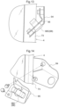
- an arrow with a reference mark F in Fig. 1 indicates the front side of the tractor
- an arrow with a reference mark U indicates the upper side of the tractor.
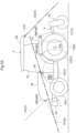
- an arrow with a reference mark F in Fig. 2 indicates the front side of the tractor
- an arrow with a reference mark R indicates the right side of the tractor.
- the tractor illustrated as an example of the present embodiment include: a vehicle body frame 1 that spans between the front and rear ends of the vehicle body; travel apparatuses 2; a prime mover part 3, a cabin 4; and a three-point linkage mechanism 5 that is used to couple a work implement apparatus thereto.
- the travel apparatuses 2 are respectively provided on the right and left of the vehicle body frame 1.
- the prime mover part 3 is located at a front portion of the vehicle body frame 1.
- the cabin 4 is located at a rear portion of the vehicle body frame 1.
- the three-point linkage mechanism 5 is attached to a rear end portion of the vehicle body frame 1 to be moved up and down .
- the vehicle body frame 1 includes a front frame 7, a case unit 8 that also serves as a rear frame, and the like.
- the front frame 7 extends from a position below an engine 6 located in the prime mover part 3, to the front side of the vehicle body.
- the case unit 8 extends from a position below the rear end of the engine 6 to the rear side of the vehicle body.
- the case unit 8 houses: a pedal-operation type main clutch; a speed change power transmission unit; and a pair of right and left side brakes.
- the main clutch connects or disconnects power from the engine 6.
- the speed change power transmission unit splits power transmitted via the main clutch into travel power and work power, and performs speed change.
- the side brakes act on the right and left travel apparatuses 2.
- the right and left travel apparatuses 2 include right and left front wheels 9 that function as drivable and steering wheels, and right and left rear wheels 10 that function as driving wheels.
- the right and left front wheels 9 are supported at the right and left ends of a wheel support member 11 that is rollingly supported by the front frame 7, so as to be drivable in a steerable state.
- the wheel support member 11 is a front wheel shaft case that houses, for example, a power transmission shaft 11A for driving the front wheels.
- the right and left rear wheels 10 are drivably supported by the case unit 8, and upper portions of the rear wheels 10 are covered by right and left rear fenders 12 located in the rear portion of the vehicle body.
- the prime mover part 3 includes: the engine 6 of a water-cooled type; a cooling fan 13; a radiator 14; a battery 15; an exhaust processing apparatus (not shown); an air cleaner (not shown); and a hood 16 that is pivotally opened and closed.
- the engine 6 is located in a rear portion of the prime mover part 3 relative to the vehicle body, which is a downstream side in a cooling direction of the prime mover part 3.
- the cooling fan 13 is located in a front portion of the vehicle body, which is the upstream side relative to the engine 6 in the cooling direction.
- the radiator 14 is located forward of the cooling fan 13 in the vehicle body.
- the battery 15 is located forward of the radiator 14 in the vehicle body.
- the exhaust processing apparatus is located above a rear portion of the engine 6.
- the air cleaner is located above a front portion of the engine 6.
- the hood 16 is configured to be pivotally opened and closed, and covers the engine 6, the radiator 14, etc. from above.
- An electronic control type diesel engine that is provided with a common rail system is employed as the engine 6.
- a DOC Diesel Oxidation Catalyst
- DPF Diesel Particulate Filter
- the cabin 4 includes a driver part 17 and a boarding space in a rear portion of the vehicle body.
- the driver part 17 includes: a clutch pedal 18; a pair of right and left brake pedals 49; a steering wheel 19 for manual steering; a shuttle lever 20 for switching to forward travel and rearward travel; a driver's seat 22; and a display unit 23.
- the clutch pedal 18 enables operation of the main clutch.
- the brake pedals 49 enable operation of the right and left side brakes.
- the steering wheel 19 enables manual steering of the right and left front wheels 9.
- the driver's seat 22 has an armrest 21 for the right arm.
- the display unit 23 includes, for example, a liquid crystal panel 23A that accepts touch operations.
- the steering wheel 19 is linked to the right and left front wheels 9 via a steering mechanism 25, and the steering mechanism 25 includes a full hydraulic type power steering unit 24.
- the armrest 21 is provided with a main shift lever 26 (see Fig. 7 ), an up/down lever 27 (see Fig. 7 ) for setting the height position of a work implement apparatus W (see Figs. 23 and 24 ), and an up/down switch 28 (see Fig. 7 ) for making an instruction to move the work implement apparatus W up and down.
- the three-point linkage mechanism 5 is driven to be moved up and down under an action made by an electronic hydraulic control type up/down driving unit 29 provided in the vehicle body.
- a work implement apparatus W such as a rotary cultivating apparatus, a plow, a disc harrow, a cultivator, a subsoiler, a sowing apparatus, and a spraying apparatus can be coupled to the three-point linkage mechanism 5. If the work implement apparatus W coupled to the three-point linkage mechanism 5 is a rotary cultivating apparatus or the like that is driven by power from the vehicle body, work power taken from the speed change unit is transmitted thereto via an external power transmission shaft.
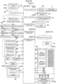
- the main ECU 30 is connected to the above-described electronic hydraulic control type up/down driving unit 29, an engine ECU 31, which is an electronic control unit for the engine, an electronic control type main transmission apparatus 32, a forward/rearward travel switching apparatus 33, a PTO clutch 34, an electronic hydraulic type brake operation unit 35, an in-vehicle information acquisition unit 36, and so on, so as to be able to communicate with them via an in-vehicle LAN such as a CAN (Controller Area Network) or a communication line.
- the main transmission apparatus 32, the forward/rearward travel switching apparatus 33, and the PTO clutch 34 are provided in the speed change power transmission unit.
- the brake operation unit 35 enables automatic operation of the right and left side brakes.
- the in-vehicle information acquisition unit 36 acquires in-vehicle information including the vehicle speed.
- the main ECU 30 and the engine ECU 31 include a microprocessor that includes a CPU, an EEPROM, and the like.
- the travel control unit 30A includes, for example, various control programs that realize control regarding the travel of the vehicle body.
- the work control unit 30B includes, for example, various control programs that realizes control regarding the work implement apparatus W.
- a hydrostatic continuously variable transmission apparatus that performs stepless transmission of travel power is employed as the main transmission apparatus 32.
- the forward/rearward travel switching apparatus 33 also serves as a travel clutch that connects or disconnects travel power.
- the speed change power transmission unit includes, in addition to the main transmission apparatus 32 and the like, an auxiliary transmission apparatus that performs stepwise transmission of travel power, a PTO transmission apparatus that performs stepwise transmission of work power, and so on.
- the in-vehicle information acquisition unit 36 includes various sensors such as a rotation sensor 37, a vehicle speed sensor 38, a first lever sensor 39, a second lever sensor 41, a third lever sensor 42, and a fourth lever sensor 43. Also, the in-vehicle information acquisition unit 36 includes various switches such as the above-described up/down switch 28, a turn lifting switch 44, a rearward travel lifting switch 45, a PTO switch 46, a height sensor 47, and a steering angle sensor 48.
- the rotation sensor 37 detects the output speed of the engine 6.
- the vehicle speed sensor 38 detects the output speed of the auxiliary transmission apparatus as the vehicle speed.
- the first lever sensor 39 detects the operation position of the main shift lever 26.
- the second lever sensor 41 detects the operation position of an auxiliary shift lever 40 that is provided in the driver part 17.
- the third lever sensor 42 detects the operation position of the shuttle lever 20.
- the fourth lever sensor 43 detects the operation position of the up/down lever 27.
- the turn lifting switch 44, the rearward travel lifting switch 45, and the PTO switch 46 are included in the driver part 17.
- the height sensor 47 detects the angle of up/down swing of right and left lift arms (not shown) of the up/down driving unit 29 as the height position of the work implement apparatus W.
- the steering angle sensor 48 detects a steering angle of the front wheels 9.
- the travel control unit 30A performs vehicle speed control to operate a trunnion shaft (not shown) of the main transmission apparatus 32 based on the output from the rotation sensor 37, the output from the vehicle speed sensor 38, the output from the first lever sensor 39, and the output from the second lever sensor 41, such that the vehicle speed reaches a control target vehicle speed obtained based on the engine speed, the operation position of the main shift lever 26, and operation position of the auxiliary shift lever 40.
- the driver can change the vehicle speed to any vehicle speed by operating the main shift lever 26 to a certain operation position.
- the travel control unit 30A performs forward/rearward travel switching control to switch the forward/rearward travel switching apparatus 33 to the power transmission state that corresponds to the operation position of the shuttle lever 20, based on the output from the third lever sensor 42.
- the driver can set the travel direction of the vehicle body to the forward direction by operating the shuttle lever 20 to a forward travel position.
- the driver can set the travel direction of the vehicle body to the rearward direction by operating the shuttle lever 20 to a rearward travel position.
- the work control unit 30B performs position control to control the action of the up/down driving unit 29 based on the output from the fourth lever sensor 43 and the output from the height sensor 47, such that the work implement apparatus W is located at the height position that corresponds to the operation position of the up/down lever 27.
- the driver can change the height position of the work implement apparatus W to any height position, by operate the up/down lever 27 to a certain operation position.
- the work control unit 30B Upon the up/down switch 28 being switched to a lifting instruction state in response to the up/down switch 28 being manually operated, the work control unit 30B performs lifting control to control the action of the up/down driving unit 29 based on a lifting instruction from the up/down switch 28 and the output from the height sensor 47, such that the work implement apparatus W is lifted to an upper limit position that has been determined in advance.
- the driver can make the work implement apparatus W be automatically lifted to the upper limit position by switching the up/down switch 28 to the lifting instruction state.
- the work control unit 30B Upon the up/down switch 28 being switched to a lowering instruction state in response to the up/down switch 28 being manually operated, the work control unit 30B performs lowering control to control the action of the up/down driving unit 29 based on a lowering instruction from the up/down switch 28, the output from the fourth lever sensor 43, and the output from the height sensor 47, such that the work implement apparatus W is lowered to a work height position that has been set using the up/down lever 27.
- the driver can make the work implement apparatus W be automatically lowered to the work height position by switching the up/down switch 28 to the lowering instruction state.
- the work control unit 30B When execution of turn-conjunctive lifting control is selected in response to the turn lifting switch 44 being manually operated, the work control unit 30B automatically performs the above-described lifting control upon detecting that the steering angle of the front wheels 9 has reached a set angle for ridge edge turn based on the output from the steering angle sensor 48 that detects the steering angle of the front wheels 9.
- the driver can make the work implement apparatus W be automatically lifted to the upper limit position in conjunction with the start of a ridge edge turn.
- the work control unit 30B When execution of rearward travel-conjunctive lifting control is selected in response to the rearward travel lifting switch 45 being manually operated, the work control unit 30B automatically performs the above-described lifting control upon detecting that the shuttle lever 20 has been manually operated to the rearward travel position based on the output from the third lever sensor 42.
- the driver can make the work implement apparatus W be automatically lifted to the upper limit position in conjunction with switching to rearward travel.
- the work control unit 30B Upon the PTO switch 46 being manually operated and the operation position of the PTO switch 46 being switched to an ON position, the work control unit 30B performs clutch ON control to switch the PTO clutch 34 to an ON state based on the switching of the PTO switch 46 to the ON position so that work power is transmitted to the work implement apparatus W.
- the driver can activate the work implement apparatus W by operating the PTO switch 46 to the ON position.
- the work control unit 30B Upon the PTO switch 46 being manually operated and the operation position of the PTO switch 46 being switched to an OFF position, the work control unit 30B performs clutch OFF control to switch the PTO clutch 34 to an OFF state based on the switching of the PTO switch 46 to the OFF position, so that work power is not transmitted to the work implement apparatus W.
- the driver can stop the work implement apparatus W by operating the PTO switch 46 to the OFF position.
- the work control unit 30B automatically performs the above-described clutch OFF control in conjunction with execution of the above-described lifting control, and automatically performs the above-described clutch ON control in conjunction with execution of the above-described lowering control.
- the driver can stop the work implement apparatus W in conjunction with the automatic lifting of the work implement apparatus W to the upper limit position, or activate the work implement apparatus W in conjunction with the automatic lowering of the work implement apparatus W to the work height position.
- a selection switch 50, and an electronic control system 51 for automated driving are provided in the tractor.
- the selection switch 50 enables the driver to select a manual driving mode, an automated driving mode, and the like, as a driving mode.
- the electronic control system 51 automatically drives the vehicle body when the automated driving mode is selected.
- the electronic control system 51 includes the above-described main ECU 30, an automatic steering unit 52, a positioning unit 53, a monitoring unit 54, and so on.
- the automatic steering unit 52 realizes automatic steering of the right and left front wheels 9.
- the positioning unit 53 measures the position and orientation of the vehicle body.
- the monitoring unit 54 monitors the surroundings of the vehicle body.
- the automatic steering unit 52 is constituted by the above-described power steering unit 24.
- the power steering unit 24 steers the right and left front wheels 9 based on an operation to rotate the steering wheel 19.
- the power steering unit 24 steers the right and left front wheels 9 based on a control instruction from the main ECU 30.
- the positioning unit 53 includes a satellite navigation apparatus 60 that measures the position and orientation of the vehicle body using a well-known GPS (Global Positioning System), which is an example of a GNSS (Global Navigation Satellite System).
- GPS Global Positioning System
- GNSS Global Navigation Satellite System
- Positioning methods using a GPS include a DGPS (Differential GPS) method and an RTK-GPS (Real Time Kinematic GPS) method, for example.
- DGPS Downifferential GPS
- RTK-GPS Real Time Kinematic GPS
- the satellite navigation apparatus 60 includes a satellite navigation antenna unit 61 that receives radio waves transmitted from a GPS satellite (not shown) and positioning data transmitted from a reference station (not shown) located at a known position.
- the reference station transmits positioning data obtained by receiving radio waves from the GPS satellite, to the satellite navigation apparatus 60.
- the satellite navigation apparatus 60 obtains the position and orientation of the vehicle body based on positioning data obtained by receiving radio waves from the GPS satellite, and positioning data from the reference station.
- the antenna unit 61 is attached to a roof 62 of the cabin 4, which is located at the top of the vehicle body, so as to increase sensitivity when receiving radio waves from a GPS satellite. Therefore, the position and orientation of the vehicle body measured using the GPS include positioning errors due to displacement of the antenna unit 61 resulting from yawing, pitching, or rolling of the vehicle body.
- the vehicle body is provided with an IMU 63 (Inertial Measurement Unit) that includes a three-axis gyroscope (not shown) and a three-direction acceleration sensor (not shown), and measures the yaw angle, the pitch angle, and the roll angle of the vehicle body, and the like, so that correction can be performed to remove the above-described positioning errors.
- the IMU 63 is provided inside the antenna unit 61 so that the amount of displacement of the above-described antenna unit 61 can be easily obtained.
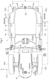
- the antenna unit 61 is attached to a right / left intermediate portion of the upper surface of a front portion of the roof 62 of the cabin 4 such that the antenna unit 61 is located at a central portion of a tread T and a central portion of a wheelbase L of the vehicle body in a plan view (see Fig. 2 ).
- the position at which the IMU 63 is attached is close to the position of the center of gravity of the vehicle body.
- the IMU 63 can promptly and accurately measure the yaw angle and the like of the vehicle body.
- the satellite navigation apparatus 60 measures the position and orientation of the vehicle body, if the antenna unit 61 is displaced due to yawing, pitching, or rolling of the vehicle body, it is possible to promptly and accurately obtain the amount of displacement of the antenna unit 61 in this case, based on, for example, the yaw angle, pitch angle, and roll angle of the vehicle body measured by the IMU 63. Then, even if positioning errors resulting from displacement of the antenna unit 61 are included in the position and orientation of the vehicle body measured by the satellite navigation apparatus 60, it is possible to promptly and accurately obtain the positioning errors based on the amount of displacement of the antenna unit 61 that can be obtained from the result of measurement performed by the IMU 63. Thus, it is possible to promptly and appropriately perform correction to remove the positioning errors from the result of measurement performed by the satellite navigation apparatus 60.
- the main ECU 30 includes an automated driving control unit 30C that includes, for example, various control programs that realize automated driving of the vehicle body.
- the automated driving control unit 30C transmits various control instructions to the travel control unit 30A, the work control unit 30B, and the like at appropriate points in time so that the vehicle body automatically travels along a preset target travel path on a farm field at a set speed while appropriately performing work, based on, for example, the target travel path and the result of positioning performed by the positioning unit 53.
- the travel control unit 30A controls the operations of the main transmission apparatus 32, the forward/rearward travel switching apparatus 33, and so on by transmitting various control instructions to the main transmission apparatus 32, the forward/rearward travel switching apparatus 33, and so on at appropriate points in time, based on various control instructions from the automated driving control unit 30C, various types of information acquired by the in-vehicle information acquisition unit 36, and so on.
- the work control unit 30B controls the operations of the up/down driving unit 29, the PTO clutch 34, and so on by transmitting various control instructions to the up/down driving unit 29, the PTO clutch 34, and so on at appropriate points in time, based on various control instructions from the automated driving control unit 30C, various types of information acquired by the in-vehicle information acquisition unit 36, and so on.
- the target travel path may be obtained by converting, into data, a travel path along which the vehicle travelled during work travel while being manually driven in a farm field, the start point of a ridge edge turn, and so on, based on the result of positioning performed by the positioning unit 53, for example.
- the target travel path may be obtained by converting, into data, a travel path along which the vehicle travelled during teaching travel while being manually driven in a farm field, the start point of a ridge edge turn, and so on, based on the result of positioning performed by the positioning unit 53, for example.
- the monitoring unit 54 includes: an obstacle detection module 64 that detects the presence or absence of an obstacle within an immediate range (e.g. within 1m) of the vehicle body; front and rear obstacle detectors 65 that detect an approaching obstacle within a short range (e.g. within 10m) of the vehicle body; a contact avoidance control unit 30D that performs contact avoidance control to avoid coming into contact with an obstacle; six monitoring cameras 66 that capture images of the surroundings of the vehicle body; an image processing apparatus 67 that processes images captured by the monitoring cameras 66; and the like.
- an obstacle detection module 64 that detects the presence or absence of an obstacle within an immediate range (e.g. within 1m) of the vehicle body
- front and rear obstacle detectors 65 that detect an approaching obstacle within a short range (e.g. within 10m) of the vehicle body
- a contact avoidance control unit 30D that performs contact avoidance control to avoid coming into contact with an obstacle
- six monitoring cameras 66 that capture images of the surroundings of the vehicle body
- an image processing apparatus 67 that processes images captured by
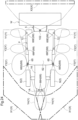
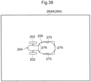
- the obstacle detection module 64 includes: eight obstacle searchers 68 that each search for an obstacle within the immediate range of the vehicle body; and two search information processing apparatuses 69 that perform processing for determining whether or not an obstacle has approached and entered the immediate range of the vehicle body, based on search information acquired from the obstacle searchers 68.
- Each obstacle searcher 68 employs, as an example of a range sensor, a sonar device that uses ultrasonic waves to measure a distance.
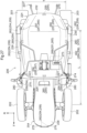
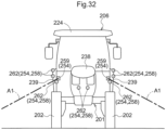
- the eight obstacle searchers 68 are distributed on the front end portion and the right and left end portions of the vehicle body such that the front side and the right and left sides of the vehicle body are search-target areas.
- Each obstacle searcher 68 transmits search information obtained by performing a search to the corresponding search information processing apparatus 69.
- Each search information processing apparatus 69 performs determination processing to determine whether or not an obstacle has approached and entered the immediate range of the vehicle body, based on the period of time from transmission to reception of an ultrasonic wave from the corresponding obstacle searcher 68, and outputs the result of determination to the contact avoidance control unit 30D.
- the obstacle detection module 64 detects the approaching obstacle. Also, no obstacle searcher 68 is provided in a rear end portion of the vehicle body, and thus the obstacle detection module 64 is prevented from misdetecting the work implement apparatus W (see Figs. 23 and 24 ) attached to the rear portion of the vehicle body so as to be able to move up and down, as an obstacle.
- the obstacle detection module 64 detects the ridge as an obstacle. Also, if a moving object has unexpectedly approached and entered the immediate range of the vehicle body, the obstacle detection module 64 detects the moving object as an obstacle.
- Each obstacle detector 65 employs a laser scanner that has a detection angle of about 270 degrees.
- Each obstacle detector 65 includes a detection unit 65A that performs detection of an obstacle, and a processing unit 65B that processes detection information from the detection unit 65A.
- the detection unit 65A irradiates a detection-target area with a laser beam and receives the reflected light.
- the processing unit 65B determines, for example, whether or not an obstacle has approached and entered a short range of the vehicle body, based on the period of time from irradiation to reception of the laser beam, and outputs the result of determination to the contact avoidance control unit 30D.
- An area on the front side of the vehicle body is set to the detection-target area of the front-side obstacle detector 65.
- An area on the rear side of the vehicle body is set to the detection-target area of the rear-side obstacle detector 65.
- the contact avoidance control unit 30D includes, for example, a control program that realizes execution of contact avoidance control, and is provided in the main ECU 30. Upon detecting that an obstacle has approached and entered the short range of the vehicle body based on the result of determination performed by each obstacle detector 65, the contact avoidance control unit 30D starts contact avoidance control in preference to automated driving that is based on control operations performed by the automated driving control unit 30C. Thereafter, the contact avoidance control unit 30D performs the contact avoidance control based on the result of determination performed by each obstacle detector 65 and each search information processing apparatus 69.
- the contact avoidance control unit 30D outputs a deceleration instruction to the travel control unit 30A upon contact avoidance control starting. Accordingly, the contact avoidance control unit 30D causes the main transmission apparatus 32 to perform a deceleration operation through a control operation performed by the travel control unit 30A, thereby reducing the vehicle speed from a set speed for normal travel to a set speed for contact avoidance. In this low-speed travel state, if the contact avoidance control unit 30D confirms that an obstacle has approached and entered the immediate range of the vehicle body based on the result of determination performed by any of the search information processing apparatuses 69, the contact avoidance control unit 30D outputs an emergency stop instruction to the travel control unit 30A and the work control unit 30B.
- the contact avoidance control unit 30D switches the forward/rearward travel switching apparatus 33 to the neutral state through a control operation performed by the travel control unit 30A, and causes the brake operation unit 35 to activate the right and left brakes, thereby braking the right and left front wheels 9 and the right and left rear wheels 10.
- the contact avoidance control unit 30D causes the work control unit 30B to switch the PTO clutch 34 to an OFF state, and stop the action of the work implement apparatus W.
- the contact avoidance control unit 30D In this low-speed travel state, if the contact avoidance control unit 30D confirms that there is no obstacle within the short range of the vehicle body based on the result of determination performed by each obstacle detector 65, the contact avoidance control unit 30D outputs an acceleration instruction to the travel control unit 30A, and then ends the contact avoidance control.
- the contact avoidance control unit 30D causes the transmission apparatus 32 to perform an acceleration operation through a control operation performed by the travel control unit 30A so that the vehicle speed is increased from the set speed for contact avoidance to the set speed for normal travel, and thereafter restarts automated driving that is based on a control operation performed by the automated driving control unit 30C.
- a wide-angle CCD camera for visible light is employed in each monitoring camera 66.
- One of the six monitoring cameras 66 is for capturing an image of objects on the front side of the vehicle body.
- This monitoring camera 66 is provided at a right / left intermediate portion in a front upper end region of the cabin 4, in an inclined orientation so as to capture forward and downward thereof.
- Two of the six monitoring cameras 66 are for capturing an image of objects located to the right of the vehicle body.
- These monitoring cameras 66 are provided at the right upper end portion of the cabin 4 with a predetermined front/rear interval, in an inclined orientation so as to capture an image downward and rightward thereof.
- Two of the six monitoring cameras 66 are for capturing an image of objects located to the left of the vehicle body. These monitoring cameras 66 are provided at the left upper end portion of the cabin 4 with a predetermined front/rear interval, in an inclined orientation so as to capture an image downward and leftward thereof. One of the six monitoring cameras 66 is for capturing an image of objects located to the rear of the vehicle body. This monitoring camera 66 is provided at a right / left intermediate portion in a rear upper end region of the cabin 4 in rear upper end region of the cabin 4, in an inclined orientation so as to capture rearward and downward thereof. As a result, it is possible to capture images of the entire surroundings of the vehicle body.
- only one right-side monitoring camera 66 and only one left-side monitoring camera 66 may be provided at appropriate positions on the right and left end of the upper end portion of the cabin 4.
- the image processing apparatus 67 processes video signals from the monitoring cameras 66, generates an image of objects on the front side of the vehicle body, an image of objects on the right side of the vehicle body, an image of objects on the left side of the vehicle body, an image of objects on the rear side of the vehicle body, a bird's eye image seen from right above the vehicle body, and so on, and transmits the images to the display unit 23 and the like.
- the display unit 23 includes, for example, a control unit 23B that changes an image displayed on the liquid crystal panel 23A, based on, for example, a manual operation made with various operation switches (not shown) displayed on the liquid crystal panel 23A.
- displaying images from the image processing apparatus 67 on the liquid crystal panel 23A makes it easier for the driver to visually check the state of the surroundings of the vehicle body and the state of work during operation.
- the driver can easily drive the vehicle body in a preferable manner according to the type of work, and so on.
- displaying images from the image processing apparatus 67 on the liquid crystal panel 23A makes it easier for the administrator to visually check the state of the surroundings of the vehicle body and the state of work during automated driving. If the administrator visually recognizes an abnormality in the surroundings of the vehicle body, the state of work, or the like during automated driving, the administrator can promptly and appropriately address the abnormality according to the type of abnormality, the degree of the abnormality, and so on.
- the electronic control system 51 includes a cooperation control unit 70.
- the cooperation control unit 70 When a cooperative driving mode is selected by manually operating the selection switch 50, the cooperation control unit 70 causes the vehicle body to automatically travel in cooperation with another vehicle that has the same specifications.
- the cooperation control unit 70 includes a communication module 71 that wirelessly communicates with another vehicle to exchange information regarding cooperative travel with the other vehicle, including information regarding the positions of the vehicle bodies, with each other, and a cooperative driving control unit 30E that performs cooperative driving control based on information from the other vehicle.
- the cooperative driving control unit 30E includes, for example, a control program that realizes execution of cooperative driving control, and is provided in the main ECU 30.
- the automated driving control unit 30C transmits various control instructions to the travel control unit 30A, the work control unit 30B, and so on at appropriate points in time so that the vehicle body automatically travels along a preset target travel path for side-by-side travel at a set speed while appropriately performing work, based on, for example, the target travel path for side-by-side travel and the result of positioning performed by the positioning unit 53.
- the cooperative driving control unit 30E determines whether or not the distance between the vehicle and another preceding vehicle in the forward travel direction, the distance between the vehicle and the other preceding vehicle in the side-by-side direction, and the like are appropriate, based on the target travel path for side-by-side travel of the vehicle, the result of positioning performed by the positioning unit 53, the target travel path for side-by-side travel of the other vehicle, position information regarding the other vehicle, and so on. If any of the distances between the vehicles is inappropriate, the cooperative driving control unit 30E starts cooperative driving control in preference to automated driving that is based on the control operation made by the automated driving control unit 30C, so that the distance of the vehicles is appropriate.
- the cooperative driving control unit 30E In cooperative driving control, if the distance between the vehicles in the forward travel direction is shorter than an appropriate distance, the cooperative driving control unit 30E outputs a deceleration instruction to the travel control unit 30A. Thus, the cooperative driving control unit 30E causes the main transmission apparatus 32 to perform a deceleration operation through a control operation performed by the travel control unit 30A, thereby returning the distance between the vehicles in the forward travel direction to the appropriate distance. Upon the distance between the vehicles in the forward travel direction returning to the appropriate distance, the cooperative driving control unit 30E restarts automated driving that is based on a control operation performed by the automated driving control unit 30C, thereby increasing the vehicle speed to the set speed for normal travel and keeping the distance between the vehicles in the forward travel direction at the appropriate distance.
- the cooperative driving control unit 30E If the distance between the vehicles in the forward travel direction is longer than the appropriate distance, the cooperative driving control unit 30E outputs an acceleration instruction to the travel control unit 30A. Thus, the cooperative driving control unit 30E causes the main transmission apparatus 32 to perform an acceleration operation through a control operation performed by the travel control unit 30A, thereby returning the distance between the vehicles in the forward travel direction to the appropriate distance. Upon the distance between the vehicles in the forward travel direction returning to the appropriate distance, the cooperative driving control unit 30E restarts automated driving that is based on a control operation performed by the automated driving control unit 30C, thereby decreasing the vehicle speed to the set speed for normal travel and keeping the distance between the vehicles in the forward travel direction at the appropriate distance.
- the cooperative driving control unit 30E If the distance between the vehicles in the side-by-side direction is longer than the appropriate distance, the cooperative driving control unit 30E outputs a steering instruction to the travel control unit 30A to travel toward the other vehicle. Thus, the cooperative driving control unit 30E causes the right and left front wheels 9 to steer toward the other vehicle through a control operation performed by the travel control unit 30A, thereby returning the distance between the vehicles in the side-by-side direction to the appropriate distance.
- the cooperative driving control unit 30E Upon the distance between the vehicles in the side-by-side direction returning to the appropriate distance, the cooperative driving control unit 30E restarts automatic driving that is based on a control operation performed by the automated driving control unit 30C, thereby returning the travel direction of the vehicle body to the travel direction for normal travel and keeping the distance between the vehicles in the side-by-side direction at the appropriate distance.
- the cooperative driving control unit 30E If the distance between the vehicles in the side-by-side direction is shorter than the appropriate distance, the cooperative driving control unit 30E outputs a steering instruction to the travel control unit 30A to travel away from the other vehicle. Thus, the cooperative driving control unit 30E causes the right and left front wheels 9 to steer away from the other vehicle through a control operation performed by the travel control unit 30A, thereby returning the distance between the vehicles in the side-by-side direction to the appropriate distance.
- the cooperative driving control unit 30E Upon the distance between the vehicles in the side-by-side direction returning to the appropriate distance, the cooperative driving control unit 30E restarts automatic driving that is based on a control operation performed by the automated driving control unit 30C, thereby returning the travel direction of the vehicle body to the travel direction for normal travel and keeping the distance between the vehicles in the side-by-side direction at the appropriate distance.
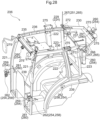
- the cabin 4 includes: a roof frame 72 that supports the roof 62 and the like; right and left front pillars 73 that support a front end portion of the roof frame 72; right and left center pillars 74 that support front/rear intermediate portions of the roof frame 72; right and left rear pillars 75 that support a rear portion of the roof frame 72; a front panel 76 that forms the front face of the cabin 4; right and left door panels 77 that are supported by the right and left center pillars 74 so as to be able to be pivotally opened and closed; right and left side panels 78 that form the rear side faces of the cabin 4; a rear panel 79 that is supported by the roof frame 72 so as to be able to be pivotally opened and closed; and the like.
- the roof frame 72 is substantially rectangular when viewed in a plan view, and includes: a front beam 98 that spans the right and left front pillars 73; right and left side beams 99 that respectively span the right and left front pillars 73 and the right and left rear pillars 75; and a rear beam 100 that spans the right and left rear pillars 75; and the like.
- the right and left front pillars 73 are provided on the front side of the vehicle body relative to a center of the wheelbase L of the vehicle body.
- the right and left front pillars 73 are provided such that the upper half portion thereof is inclined to the right / left center of the vehicle body, approaching the upper side, when viewed from the front, and the upper half portion thereof is curved to the center in the front-rear direction of the vehicle body, approaching the upper side, when viewed from the side.
- the right and left center pillars 74 and the right and left rear pillars 75 are arranged between the respective right and left rear fenders 12 located on the right and left of the driver's seat 22 and the roof frame 72.
- the right and left center pillars 74 are provided such that they are curved to the center in the right-left direction of the vehicle body, approaching the upper side, when viewed from the front, and they are curved to the center in the front-rear direction of the vehicle body, approaching the upper side, when viewed from the side.
- the right and left rear pillars 75 are provided such that they are curved to the center in the right-left direction of the vehicle body toward the upper portion side, when viewed from the front, and they are substantially perpendicular, when viewed from the side.
- the panels 76 to 79 are curved panels that are curved along the corresponding pillars 73 to 75, and the like, and are made of glass or a transparent acrylic resin, for example.
- the cabin 4 includes an auxiliary frame 90 that extends rearward from the upper end portions of the right and left rear pillars 75.
- the auxiliary frame 90 supports the rear-side obstacle detector 65, the monitoring camera 66 for image capturing of the rear side, and the like.
- the obstacle searchers 68 are set at positions at least above the right and left front wheels 9 of the vehicle body.
- the distances between the obstacle searchers 68 and the ground in such a case can be kept larger than the search distance of the obstacle searchers 68.
- the obstacle searchers 68 are arranged at appropriate height positions at which it is possible to avoid, even if, during work travel, the vehicle body has rolled or pitched due to unevenness of the farm field or the like, the risk of the ground of the farm field entering the search distance of the obstacle searchers 68.
- the obstacle searchers 68 it is possible to prevent the obstacle searchers 68 from misdetecting the ground of a farm field as an obstacle due to rolling or pitching of the vehicle body during work travel.
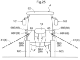
- two first obstacle searchers 68A are attached to up/down intermediate portions of the front end portion of the hood 16, with a predetermined distance from each other in the right-left direction.
- the search-target area on the front side of the vehicle body can be increased in the right-left direction.
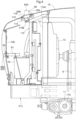
- two second obstacle searchers 68B are attached to positions on the right and left side portions of the hood 16, the positions being located above the right and left front wheels 9.
- Two third obstacle searchers 68C are attached to the right and left front pillars 73 of the cabin 4 that are located at front/rear intermediate portions of the vehicle body.
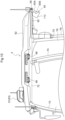
- Two fourth obstacle searchers 68D are attached to positions on the right and left rear fenders 12, the positions being located above the right and left rear wheels 10.
- the right and left lateral sides of the front portion of the vehicle body, in which the hood 16 and the like are arranged, are search-target areas of the right and left second obstacle searchers 68B;
- the right and left lateral sides of the front/rear intermediate portions of the vehicle body, in which the right and left front pillars 73 and the like are arranged, are search-target areas of the right and left third obstacle searchers 68C;
- the right and left lateral sides of the rear portion of the vehicle body, in which the right and left rear fenders 12 and the like are arranged, are search-target areas of the right and left fourth obstacle searchers 68D.
- each obstacle searcher 68 it is possible to more reliably avoid the risk that the vehicle body will come into contact with an obstacle during automated driving, based on a search performed by each obstacle searcher 68.
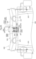
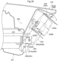
- the right and left first obstacle searchers 68A are attached to a first support member 91 via respective first resonance prevention member 92 made of resin, wherein the first support member 91 is formed of a steel plate and is arranged at an up/down intermediate portion in a front end region of the hood 16.
- the right and left second obstacle searchers 68B are attached to second support members 93 via another first resonance prevention member 92 made of resin, respectively, wherein each of the second support member 93 is formed of a steel plate and arranged at right / left front end portion of the hood 16.
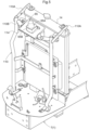
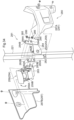
- the right and left third obstacle searchers 68C are attached to third support members 94 via second resonance prevention member 95 made of resin, respectively, wherein each of the third support member 94 is formed of a steel plate and arranged at up/down intermediate portion of the right / left front pillar 73.
- the right and left fourth obstacle searchers 68D are attached to fourth support members 96 via third resonance prevention members 97 made of resin, respectively, wherein each of the fourth support members 96 is formed of a steel plate and protrudes laterally outward of the vehicle body from an upper end portions of the right / left rear fender 12.
- the obstacle searchers 68 which each include an oscillator (not shown) are directly attached to the support members 91, 93, 94, and 96 that are made of steel plates. Furthermore, because the first resonance prevention members 92 of the same type are used for attaching the first obstacle searchers 68A and the second obstacle searchers 68B to the hood 16, use of the members of the same type makes it possible to realize a reduction in cost.
- the first support member 91 is attached to a reinforcement frame 106 provided in the front end portion of the hood 16.
- the reinforcement frame 106 also serves as a support frame for supporting headlights 107 arranged in the upper portion of the front end of the hood 16, and the like.
- the right and left third obstacle searchers 68C are located between the right and left front wheels 9 and the right and left rear wheels 10, as a result of being attached to the right and left front pillars 73. Accordingly, the search-target areas of the right and left third obstacle searchers 68C can include the area between the right and left front wheels 9 and the right and left rear wheels 10, and the right and left third obstacle searchers 68C can detect presence or absence of an obstacle between the right and left front wheels 9 and the right and left rear wheels 10.
- the right and left fourth obstacle searchers 68D are located higher than the lateral outer ends of the right and left rear wheels 10, as a result of being attached to the right and left rear fenders 12 via the right and left fourth support members 96. Accordingly, the right and left fourth obstacle searchers 68D can favorably search for an obstacle, without interference from the right and left rear wheels 10.
- the attachment orientation of the right-side first obstacle searcher 68A is set to a forward right orientation in which its transmission/reception surface is directed forward and right.
- the attachment orientation of the left-side first obstacle searcher 68A is set to a forward left orientation in which its transmission/reception surface is directed forward and left.
- the attachment orientation of the right-side second obstacle searcher 68B is set to a rightward orientation in which its transmission/reception surface is directed laterally right.
- the attachment orientation of the left-side second obstacle searcher 68B is set to a leftward orientation in which its transmission/reception surface is directed laterally left.
- the orientations of attaching the right-side third obstacle searcher 68C and fourth obstacle searcher 68D are set to a downward right orientation in which their transmission/reception surfaces are directed downward and right.
- the orientations of attaching the left-side third obstacle searcher 68C and fourth obstacle searcher 68D are set to a downward left orientation in which their transmission/reception surfaces are directed downward and left.
- the front-side obstacle detector 65 is located at a right / left intermediate portion of the front upper portion of the prime mover part 3.
- the rear-side obstacle detector 65 is located at a right / left intermediate portion of the rear upper portion of the cabin 4.
- the front-side obstacle detector 65 can also serve as a sighting device that is used by a driver to determine the direction in which the vehicle body travels. As a result, it is possible to keep the vehicle body from coming into contact with an obstacle that is present in front of the vehicle body, during automated driving, while realizing a reduction in cost due to the obstacle detector also serving as a sighting device.
- the rear-side obstacle detector 65 may be arranged in the upper portion of the vehicle body at a position higher than the work implement apparatus W (see Figs. 23 and 24 ) that is mounted to the rear portion of the vehicle body so as to be able to move up and down. Accordingly, the rear-side obstacle detector 65 can favorably detect an obstacle that has approached and entered the short range of the work implement apparatus W mounted in the rear portion of the vehicle body, without interference from the work implement apparatus W. As a result, it is possible to avoid the risk that the work implement apparatus W mounted in the rear portion of the vehicle body will come into contact with an obstacle during automated driving.
- the front-side and rear-side obstacle detectors 65 are located at positions higher than the upper portion of the prime mover part 3 of the vehicle body, even if, during work travel for example, any obstacle detector 65 approaches the ground of a farm field due to rolling or pitching of the vehicle body resulting from unevenness of the farm field, or the like, the obstacle detectors 65 are set at height positions at which the distances between the obstacle detectors 65 and the ground at that time can be easily kept larger than the detection distance of the obstacle detectors 65.
- the obstacle detectors 65 are arranged at appropriate height positions at which, if, during work travel, the vehicle body rolls or pitches due to unevenness of a farm field, or the like, the ground of the farm field is unlikely to enter the detection distance ranges of the obstacle detectors 65.
- the obstacle detectors 65 it is possible to prevent the obstacle detectors 65 from misdetecting the ground of a farm field as an obstacle due to rolling or pitching of the vehicle body during work travel.
- the front-side obstacle detector 65 is located on the upstream side, in the cooling direction, relative to the radiator 14, which is located on the upstream side in the cooling direction of the prime mover part 3. Accordingly, it is possible to avoid heat damage that may be caused by heated cooling air used to cool, thus heated by the engine 6, the radiator 14, and the like reaching the front-side obstacle detector 65.
- the prime mover part 3 is provided with a support frame 110 that is attached to the front frame 7 in an upright orientation.
- the support frame 110 includes, on the upper portion thereof, right and left arm portions 110A that support the right and left end portions of the radiator 14, and a supporting portion 110B that supports the front-side obstacle detector 65.
- the front-side obstacle detector 65 is coupled, using bolts, to the supporting portion 110B via a supporting plate 111 and right and left vibration-proof rubber elements 112.
- the hood 16 has an opening 16A through which the detection unit 65A of the front-side obstacle detector 65 is exposed to the upper side from the hood 16 at the closed position.
- a U-shaped support member 113 for supporting the rear-side obstacle detector 65 is attached to the rear end of the auxiliary frame 90 of the cabin 4.
- the rear-side obstacle detector 65 is coupled, using bolts, to the support member 113 via the supporting plate 111 and the right and left vibration-proof rubber elements 112.
- the supporting structure and vibration-proof structure that are required to attach the front-side obstacle detector 65 can be simplified.
- the detection unit 65A of the obstacle detector 65 which is exposed to the upper side of the hood 16 from the opening 16A formed in the hood 16 at the closed position, can detect an obstacle that has approached and entered the short range of the front portion of the vehicle body during automated driving, while realizing simplification of the supporting structure and vibration-proof structure in this manner.
- the supporting portion 110B of the support frame 110 includes an outer enclosing member 114 that encloses the detection unit 65A of the front-side obstacle detector 65.
- the outer enclosing member 114 includes a ring-shaped dustproof member 115 that is made of a sponge, the dustproof member 115 being located between the upper surface of the outer enclosing member 114 and the hood 16 at the closed position, and preventing dust from entering the hood 16 via the opening 16A of the hood 16.
- a rubber trim 116 is attached to and covers the circumferential edge of the opening 16A of the hood 16. Accordingly, it is possible to avoid the risk that, when an operation for opening/closing the hood 16 is performed, the front-side obstacle detector 65 will come into contact with the edge of the opening of the hood 16 and may be damaged.
- the present invention is not limited to the configurations exemplified in the above-described first embodiment.
- other representative configurations of the present invention will be given as examples.
- the work vehicle may have a semi-crawler type configuration in which it is provided with right and left crawlers instead of the right and left rear wheels 10.
- the work vehicle may have a full-crawler type configuration in which it is provided with right and left crawlers instead of the right and left front wheels 9 and the right and left rear wheels 10.
- the work vehicle may be of a two-wheel drive type in which either the right and left front wheels 9 or the right and left rear wheels 10 are driven.
- the work vehicle may have an electric type configuration in which it is provided with an electric motor instead of the engine 6.
- the work vehicle may have a hybrid type configuration in which it is provided with the engine 6 and an electric motor.
- the work vehicle may be provided with a protection frame instead of the cabin 4.
- obstacle searchers 68 may be provided, and if the work vehicle is short in length, six or less obstacle searchers 68 may be provided.
- an obstacle searcher 68 may be attached to the protection frame.
- each obstacle searcher 68 An infrared range sensor or the like may be employed as each obstacle searcher 68.
- the right and left first obstacle searchers 68A may be located at positions higher than the headlights 107 provided in the front end portion of the hood 16.
- the contact avoidance control unit 30D may be configured to output an emergency stop instruction to the travel control unit 30A and the work control unit 30B upon confirming that an obstacle has approached and entered the immediate range of the vehicle body, based on the result of determination performed by one of the obstacle detection module 64 and the front-side and rear-side obstacle detectors 65, or the result of determination performed by the obstacle detection module 64 and one of the front-side and rear-side obstacle detectors 65.
- the front-side and rear-side obstacle detectors 65 may each serve also as the obstacle detection module 64.
- an obstacle detector 65 may be located at a right / left intermediate portion of the upper portion of the protection frame.
- two obstacle detectors 65 may be provided on either front or rear side, at positions away from the right / left intermediate portion of the vehicle body in a right / left symmetrical manner.
- a tractor (which is an example of a "work vehicle”) includes: a vehicle body frame 1 that spans between the front and rear ends of the vehicle body; right and left travel apparatuses 2 arranged to the right and left of the vehicle body frame 1; a prime mover part 3 that is located in a front portion of the vehicle body frame 1; a cabin 4 that is located in a rear portion of the vehicle body frame 1; and a three-point linkage mechanism 5 that is used to couple a work implement apparatus W (see Figs. 23 and 24 ) attached to a rear end portion of the vehicle body frame 1 to be moved up and down.
- a weight 1A is attached to a front end portion of the vehicle body frame 1.
- the vehicle body frame 1 includes a front frame 7 that extends from a position below an engine 6 located in the prime mover part 3 to the front side of the vehicle body, a case unit 8 that extends from a position below the rear end of the engine 6 to the rear side of the vehicle body and serves also as a rear frame, and the like.
- the configurations of the front frame 7, the case unit 8, and the like are the same as those of the above-described first embodiment.
- the right and left travel apparatuses 2 include right and left front wheels 9 that function as drivable and steering wheels, and right and left rear wheels 10 that function as driving wheels.
- the configurations of the front wheels 9, the rear wheels 10, a wheel support member 11, and the like are the same as those of the above-described first embodiment.
- the three-point linkage mechanism 5 that is shown in Figs. 19 to 21 , etc. is driven to be moved up and down under an action made by an electronic hydraulic control type up/down driving unit 29 provided in the vehicle body.
- any of various work implement apparatuses W such as a rotary cultivating apparatus, a plow, a disc harrow, a cultivator, a subsoiler, a sowing apparatus, and a spraying apparatus can be coupled to the three-point linkage mechanism 5. If the work implement apparatus W coupled to the three-point linkage mechanism 5 is a rotary cultivating apparatus or the like that is driven by power from the vehicle body, work power taken from the speed change unit is transmitted to the work implement apparatus W via an external power transmission shaft.
- the main ECU 30 includes a travel control unit 30A that performs control regarding travel of the vehicle body, a work control unit 30B that performs control regarding the work implement apparatus, and the like, and the configuration of the main ECU 30 is as described above in the first embodiment. Furthermore, the configuration of the engine ECU 31 is the same as that of the above-described first embodiment.
- the configurations of an electronic control type main transmission apparatus 32 and a forward/rearward travel switching apparatus 33 that are provided in the speed change power transmission unit are the same as those of the above-described first embodiment. Furthermore, the configuration of the speed change power transmission unit is the same as that of the above-described first embodiment.
- an in-vehicle information acquisition unit 36 includes various sensors and switches, such as: a rotation sensor 37 that detects the output speed of the engine 6; a vehicle speed sensor 38 that detects the output speed of an auxiliary transmission apparatus as the vehicle speed; a first lever sensor 39 that detects the operation position of the main shift lever 26; a second lever sensor 41 that detects the operation position of an auxiliary shift lever 40 that is provided in the driver part 17; a third lever sensor 42 that detects the operation position of the shuttle lever 20; a fourth lever sensor 43 that detects the operation position of the up/down lever 27; an up/down switch 28 as described above; a turn lifting switch 44, a rearward travel lifting switch 45 and a PTO switch 46 that are provided in the driver part 17; a height sensor 47 that detects the angle of an up/down swing of right and left lift arms (not shown) of the up/down driving unit 29 as the height position of the work implement apparatus W; and a steering angle sensor 48 that detects a steering angle of the
- the travel control unit 30A includes, for example, various control programs that realize control regarding travel of the vehicle body.
- the work control unit 30B includes, for example, various control programs that realize control regarding the work implement apparatus W.
- the configuration, functions, and effects of the travel control unit 30A are as described in the first embodiment. Furthermore, the configuration, functions, and effects of the work control unit 30B are as described in the first embodiment.
- a selection switch 50 that enables the driver to select, as a driving mode thereof, one of a manual driving mode, an automated driving mode and the like; and an electronic control system 51 for automated driving that automatically drives the vehicle body when the automated driving mode is selected are provided in the tractor.
- the electronic control system 51 includes: the above-described main ECU 30; an automatic steering unit 52 that realizes automatic steering of the right and left front wheels 9; a positioning unit 53 that measures the position and orientation of the vehicle body; a monitoring unit 54 that monitors the surroundings of the vehicle body, and the like.
- the configurations of the automatic steering unit 52 and the positioning unit 53 are as described in the first embodiment.
- the main ECU 30 includes an automated driving control unit 30C that includes, for example, various control programs that realize automated driving of the vehicle body.
- the configuration, functions and effects of the automated driving control unit 30C are as described in the first embodiment.
- the monitoring unit 54 includes: an obstacle detection module 64 that detects the presence or absence of an obstacle; a travel regulation control unit 30F that performs, upon the obstacle detection module 64 detecting an obstacle, travel regulation control (contact avoidance control to avoid coming into contact with an obstacle) to prevent the vehicle body from traveling; four monitoring cameras 66 that capture images of the surroundings of the vehicle body; an image processing apparatus 67 that processes images captured by the monitoring cameras 66, and the like.
- Figs. 23 to 25 schematically show the detection-target areas X of the obstacle detectors 65 and the search-target areas Y of the obstacle searchers 68.
- the search-target areas Y of the obstacle searchers 68 include an area that is located below the detection-target areas X of the obstacle detectors 65. Note that, in Figs. 23 to 25 , some portions of the detection-target areas X and the search-target areas Y are omitted for convenience of illustration.
- each obstacle searcher 68 An ultrasonic sonar device that uses ultrasonic waves to measure distance is employed in each obstacle searcher 68, the ultrasonic sonar device serving as an example of a range sensor.
- Eight obstacle searchers 68 are distributed on the front end portion and the right and left end portions of the vehicle body such that the front side and the right and left sides of the vehicle body are search-target areas Y.
- Each obstacle searcher 68 has a substantially conical search-target area Y.
- Each obstacle searcher 68 transmits search information obtained by performing a search to the corresponding search information processing apparatus 69.
- the obstacle detection module 64 detects the approaching obstacle.
- the obstacle detection module 64 detects the ridge as an obstacle. Also, if a moving object has unexpectedly approached and entered the immediate range of the vehicle body, the obstacle detection module 64 detects the moving object as an obstacle.
- Each obstacle detector 65 employs a laser scanner that has a planar detection-target area X and a detection angle of up to about 270 degrees.
- Each obstacle detector 65 includes a detection unit that performs detection of an obstacle, and a processing unit that processes detection information from the detection unit.
- the detection unit irradiates a detection-target area X with a laser beam and receives the reflected light.
- the processing unit determines, for example, whether or not an obstacle has approached and entered a short range of the vehicle body, based on the period of time from irradiation to reception of the laser beam, and outputs the result of determination to the travel regulation control unit 30F.
- An area on the front side of the vehicle body is set as the detection-target area X of a front-side obstacle detector 65.
- a pair of right and left obstacle detectors 65 are provided that have first detection-target areas X1 on the front side and the lateral sides of the vehicle body, and detect an obstacle that is present in the first detection-target areas X1.
- an area on the rear side of the work implement apparatus W of the vehicle body is set as a second detection-target area X2, and a rear-side obstacle detector 102 is provided that detects an obstacle that is present in the second detection-target area X2.
- the first detection-target areas X1 and the second detection-target area X2 are set as areas in which the ground of the farm field is not detected.
- each obstacle detector 65 is attached to a support frame that extends in the up-down direction.
- the support frames are front pillars 73 included in the cabin 4.
- each obstacle detector 65 is located between an outer end, in the right-left direction, of the hood 16 and an outermost position M of the main part of the vehicle body. Furthermore, each obstacle detector 65 is located between an upper end portion of the hood 16 and the upper end portion of the front wheels 9, with respect to the up-down direction. Furthermore, each obstacle detector 65 is located in a front/rear intermediate portion of the main part of the vehicle body.
- the front/rear intermediate portion of the main part of the vehicle body means an area that is broad to some extent including areas extending forward and rearward from the front/rear center of the main part of the vehicle body.
- each obstacle detector 65 is located between a front wheel shaft 9A of the front wheels 9 and a rear wheel shaft 10A of the rear wheels 10 in the front-rear direction of the vehicle. Accordingly, it is possible to set the first detection-target areas X1 so that an obstacle can be favorably detected even when the vehicle body is inclined due to an irregular landform.
- the first detection-target area X1 of each obstacle detector 65 is set to be inclined forward, rearward, leftward, and rightward with respect to the horizontal plane. More specifically, as shown in Fig. 23 , the detection-target area X of each obstacle detector 65 is inclined forward and downward, as well as rearward and upward. Furthermore, the first detection-target areas X1 of the obstacle detectors 65 are set so as to extend over the upper front side of the front wheels 9. Furthermore, the first detection-target areas X1 of the obstacle detectors 65 are set so as to extend over the upper front side of the weight 1A. Also, as shown in Fig. 25 , the first detection-target areas X1 of the obstacle detectors 65 are inclined downward from the laterally inner side of the body toward the laterally outer side of the body.
- an area on the rear side of the vehicle body relative to the work implement apparatus W is set as the second detection-target area X2 of the rear-side obstacle detector 102.
- the second detection-target area X2 of the rear-side obstacle detector 102 is set to have a rearward and downward inclination angle.
- the second detection-target area X2 is set to be larger in width in the right-left direction than the lateral width of the work implement apparatus W.
- the travel regulation control unit 30F shown in Fig. 22 includes, for example, a control program that realizes execution of travel regulation control.
- the travel regulation control unit 30F Upon detecting that an obstacle has approached and entered the short range of the vehicle body based on the result of determination performed by each obstacle detector 65 and the rear-side obstacle detector 102, the travel regulation control unit 30F starts travel regulation control in preference to automated driving that is based on control operation performed by the automated driving control unit 30C. Thereafter, the travel regulation control unit 30F performs the travel regulation control based on the result of determination performed by each obstacle detector 65, the rear-side obstacle detector 102, and each search information processing apparatus 69.
- the travel regulation control unit 30F outputs a deceleration instruction to the travel control unit 30A upon travel regulation control starting. Accordingly, the travel regulation control unit 30F causes the main transmission apparatus 32 to perform a deceleration operation through a control operation performed by the travel control unit 30A, thereby reducing the vehicle speed from a set speed for normal travel to a set speed for contact avoidance. In this low-speed travel state, if the travel regulation control unit 30F confirms that an obstacle has approached and entered the immediate range of the vehicle body based on the result of determination performed by any of the search information processing apparatuses 69, the travel regulation control unit 30F outputs an emergency stop instruction to the travel control unit 30A and the work control unit 30B.
- the travel regulation control unit 30F switches the forward/rearward travel switching apparatus 33 to the neutral state through a control operation performed by the travel control unit 30A, and causes the brake operation unit 35 to activate the right and left brakes, thereby braking the right and left front wheels 9 and the right and left rear wheels 10.
- the travel regulation control unit 30F causes the work control unit 30B to switch the PTO clutch 34 to an OFF state, and stop the action of the work implement apparatus W.
- the travel regulation control unit 30F In this low-speed travel state, if the travel regulation control unit 30F confirms that there is no obstacle within the short range of the vehicle body based on the result of determination performed by each obstacle detector 65, the travel regulation control unit 30F outputs an acceleration instruction to the travel control unit 30A, and then ends the travel regulation control.
- the travel regulation control unit 30F causes the transmission apparatus 32 to perform an acceleration operation through a control operation performed by the travel control unit 30A so that the vehicle speed is increased from the set speed for contact avoidance to the set speed for normal travel, and thereafter restarts automated driving that is based on a control operation performed by the automated driving control unit 30C.
- a wide-angle CD camera for visible light is employed in each monitoring camera 66 shown in Figs. 19 to 22 , etc.
- One of the four monitoring cameras 66 is for capturing an image of objects on the front side of the vehicle body.
- This monitoring camera 66 is provided at a right / left center portion in a front upper end region of the cabin 4 in an inclined orientation so as to capture images forward and downward thereof.
- One of the four monitoring cameras 66 is for capturing an image of objects located to the right of the vehicle body.
- This monitoring camera 66 is provided in a right upper end portion of the cabin 4 in an inclined orientation so as to capture an image downward and rightward thereof.
- One of the four monitoring cameras 66 is for capturing an image of objects located to the left of the vehicle body.
- This monitoring camera 66 is provided in a left upper end portion of the cabin 4 in an inclined orientation so as to capture an image downward and leftward thereof.
- One of the four monitoring cameras 66 is for capturing an image of objects on the rear side of the vehicle body.
- This monitoring camera 66 is provided at a right / left center portion in a rear upper end region of the cabin 4, in an inclined orientation so as to capture images rearward and downward thereof. As a result, it is possible to capture images of the entire surroundings of the vehicle body.
- the image processing apparatus 67 shown in Fig. 22 processes video signals from the monitoring cameras 66, generates an image of objects on the front side of the vehicle body, an image of objects on the right side of the vehicle body, an image of objects on the left side of the vehicle body, an image of objects on the rear side of the vehicle body, a bird's eye image seen from right above the vehicle body, and so on; and transmits the images to the display unit 23 and the like.
- the configuration, functions, and effects of the display unit 23 are as described above in the first embodiment.
- the electronic control system 51 includes a cooperation control unit 70.
- the cooperation control unit 70 When a cooperative driving mode is selected by manually operating the selection switch 50, the cooperation control unit 70 causes the vehicle body to automatically travel in cooperation with another vehicle that has the same specifications.
- the cooperation control unit 70 includes a communication module 71 that wirelessly communicates with another vehicle to exchange information regarding cooperative travel with the other vehicle, including information regarding the positions of the vehicle bodies, with each other, and a cooperative driving control unit 30E that performs cooperative driving control based on information from the other vehicle.
- the cooperative driving control unit 30E includes, for example, a control program that realizes execution of cooperative driving control, and is provided in the main ECU 30. The configuration, functions, and effects of the cooperative driving control unit 30E are as described above in the first embodiment.
- the cabin 4 includes, for example, a roof frame 72, front pillars 73, center pillars 74, rear pillars 75, a front panel 76, door panels 77, side panels 78, and a rear panel 79.
- the right and left front pillars 73 are provided on the front side of the vehicle body relative to a center of the wheelbase L of the vehicle body.
- the right and left front pillars 73 are provided such that, when viewed from the front side, an upper half portion thereof is curved toward the right / left center of the vehicle body as it approaches the upper side of the upper half portion; and such that, when viewed from the side, the upper half portion thereof is curved toward the front-rear center of the vehicle body as it approaches the upper side of the upper half portion.
- a direction indicator 108 (blinker) is supported on each of the right and left front pillars 73.
- a rearview mirror 101 is supported at a position above the direction indicator 108 of each of the right and left front pillars 73.
- the rearview mirror 101 is rotatable about a vertical shaft and adjustable, the mirror being adjustable forward, rearward, leftward, and rightward.
- the cabin 4 includes an auxiliary frame 90 that extends rearward from the upper end portions of the right and left rear pillars 75.
- the auxiliary frame 90 supports the rear-side obstacle detector 102, the monitoring camera 66 for capturing images on the rear side, and the like.
- the obstacle searchers 68 are set at positions at least above the right and left front wheels 9 of the vehicle body.
- the distances between the obstacle searchers 68 and the ground in such a case can be kept larger than the search distance of the obstacle searchers 68.
- the obstacle searchers 68 are located at appropriate height positions at which it is possible to avoid, even if, during work travel, the vehicle body rolls or pitches due to unevenness of the farm field or the like, the risk of the ground of the farm field entering the search distance of the obstacle searchers 68.
- the obstacle searchers 68 it is possible to prevent the obstacle searchers 68 from misdetecting the ground of a farm field as an obstacle due to rolling or pitching of the vehicle body during work travel.
- the obstacle searchers 68 include: a pair of right and left first obstacle searchers 68E set for the first search-target areas Y1 on the lateral sides of the rear end portion of the main part of the vehicle body; a pair of right and left second obstacle searchers 68F set for the second search-target areas Y2 on the lateral sides of the front/rear intermediate portions of the vehicle body; a pair of right and left third obstacle searchers 68G set for the third search-target areas Y3 located on the lateral sides of the front/rear intermediate portions of the vehicle body and forwardly of the second obstacle searchers 68F; and a pair of right and left fourth obstacle searchers 68H set for the fourth search-target areas Y4 on the front side of the vehicle body.
- the two first obstacle searchers 68E are attached to rear portions of the rear fenders 12. More specifically, the first obstacle searchers 68E are attached to the right and left rear fenders 12 at positions on the rear side of the rear wheel shaft 10A of the right and left rear wheels 10.
- the first obstacle searchers 68E can each detect an obstacle that is present in the corresponding first search-target area Y1.
- the first search-target areas Y1 are set to extend laterally outward and downward from the first obstacle searchers 68E.
- the two second obstacle searchers 68F are attached to front portions of the rear fenders 12.
- the second obstacle searchers 68F can each detect an obstacle that is present in the corresponding second search-target area Y2.
- the second search-target areas Y2 are set to extend laterally outward and downward from the second obstacle searchers 68F.
- the two third obstacle searchers 68G are attached to the right and left front pillars 73 of the cabin 4 that are located at front/rear intermediate portions of the vehicle body.
- the third obstacle searchers 68G can each detect an obstacle that is present in the corresponding third search-target area Y3.
- the third search-target areas Y3 are set to extend laterally outward and downward from the third obstacle searchers 68G.
- the pair of right and left fourth obstacle searchers 68H are attached to the up/down intermediate portions of the front end portion of the hood 16, with a predetermined distance between each other in the right-left direction.
- the fourth obstacle searchers 68H can each detect an obstacle that is present in the corresponding fourth search-target area Y4.
- the search-target areas Y on the front side of the vehicle body can be increased in the right-left direction.
- the fourth search-target areas Y4 are set to extend laterally outward and downward from the fourth obstacle searchers 68H.
- the third obstacle searchers 68G and the obstacle detectors 65 are arranged below the rearview mirrors 101.
- the first search-target areas Y1 of the first obstacle searchers 68E shown in Figs. 23 and 24 , and the second detection-target areas X2 of the rear-side obstacle detectors 102 are each appropriately adjustable according to the type or the width in the right-left direction of the work implement apparatus W.
- the detection-target areas X have limits that are set at the outer edges of the areas, so that detection of the ground, instead of an obstacle, can be prevented. Note that, in Fig. 24 , the ends in the right-left direction of the first detection-target areas X1 are straight, which are schematically shown for convenience of illustration.
- the right and left lateral sides of the rear portion of the main part of the vehicle body, in which the right and left rear fenders 12 and the like are arranged are the first search-target areas Y1 of the right and left first obstacle searchers 68E; the front side of the rear wheels 10 of the main part of the vehicle body, in which the right and left rear fenders 12 and the like are arranged, are the second search-target areas Y2 of the right and left second obstacle searchers 68F; and the right and left lateral sides of the front/rear intermediate portions of the vehicle body, in which the right and left front pillars 73 and the like are arranged, are the third search-target areas Y3 of the right and left third obstacle searchers 68G.
- each obstacle searcher 68 it is possible to more reliably keep, based on a search performed by each obstacle searcher 68, the vehicle body from shifting to a travel state when a moving obstacle (such as an animal or an object rolling with wind) has approached the stopped vehicle body, and keep the vehicle body during automated driving from coming into contact with the obstacle.
- a moving obstacle such as an animal or an object rolling with wind
- the right and left first obstacle searchers 68E are attached to the right and left rear fenders 12 via right and left support members.
- the right and left first obstacle searchers 68E are respectively located above the lateral outer ends of the right and left rear wheels 10. Accordingly, the right and left first obstacle searchers 68E can favorably search for an obstacle without interference from the right and left rear wheels 10.
- the right and left third obstacle searchers 68G are attached to the right and left front pillars 73.
- the right and left third obstacle searchers 68G are respectively located between the right and left front wheels 9 and the right and left rear wheels 10.
- the search-target areas Y of the right and left third obstacle searchers 68G can include the areas between the right and left front wheels 9 and the right and left rear wheels 10, and thus the right and left third obstacle searchers 68G can detect presence or absence of an obstacle between the right and left front wheels 9 and the right and left rear wheels 10.
- the attachment orientation of the left-side first obstacle searcher 68E is set to a downward left orientation in which its transmission/reception surface is directed downward and left.
- the attachment orientation of the right-side first obstacle searcher 68E is set to a downward right orientation in which its transmission/reception surface is directed downward and right.
- the attachment orientation of the left-side second obstacle searcher 68F is set to a leftward orientation in which its transmission/reception surface is directed laterally left.
- the attachment orientation of the right-side second obstacle searcher 68F is directed to rightward orientation in which its transmission/reception surface is directed laterally right.
- the attachment orientation of the left-side third obstacle searcher 68G is set to a downward left orientation in which the transmission/reception surface is directed downward and left.
- the attachment orientation of the right-side third obstacle searcher 68G is set to a downward right orientation in which its transmission/reception surface is directed downward and right.
- the orientations of attaching the right and left fourth obstacle searchers 68H are set to forward orientations in which their transmission/reception surfaces are directed forward.
- the areas indicated by bold long dash-dotted lines in Fig. 24 are areas in which an obstacle that is present at a position lower than a predetermined height can be detected by the obstacle detectors 65. Furthermore, the areas indicated by thin long dash-dotted lines in Fig. 24 are areas in which an obstacle that is present at a position lower than the predetermined height cannot be detected by the obstacle detectors 65.
- the first search-target areas Y1 of the first obstacle searchers 68E, the second search-target areas Y2 of the second obstacle searchers 68F, and the third search-target areas Y3 of the third obstacle searchers 68G cover the areas on the lateral sides of the vehicle body (blind areas of the obstacle detectors 65) that are not included in the detection-target areas X of the obstacle detectors 65, and an obstacle can be detected in these areas.
- blind areas in which an obstacle cannot be detected can be reduced in the surroundings of the vehicle body. Accordingly, it is possible to accurately detect an obstacle present in the surroundings of the vehicle body in a traveling state, and stop traveling of the vehicle body before coming into contact with the obstacle. Also, if a moving obstacle (such as an animal or an object rolling in the wind) has moved and approached the vicinity of the vehicle body in a stopped state, it is possible to accurately detect this obstacle and prevent the vehicle body from shifting from the stopped state to the travel state, thereby avoiding an issue such as the travel apparatuses 2 or the work implement apparatus W running over the obstacle.
- a moving obstacle such as an animal or an object rolling in the wind
- the work vehicle does not need to include a pair of right and left obstacle detectors 65.
- the first detection-target area X1 of the left obstacle detector 65 and the first detection-target area X1 of the right obstacle detector 65 may be arranged in a right / left asymmetrical shape. Also, only one obstacle detector 65 may be provided on the right or left side.
- the obstacle detectors 65 do not need to be attached to the front pillars 73.
- the obstacle detectors 65 may be attached to the rearview mirrors 101.
- the obstacle detectors 65 may also be attached to frames located in the vicinity of the direction indicators 108. By arranging the obstacle detectors 65 in the vicinity of the direction indicators 108, wiring can be realized such that a harness for the obstacle detectors 65 and a harness for the direction indicators 108 can be joined together.
- a gate-shaped ROPS (Roll Over Protective Structure) frame may be provided that is located behind the driver's seat 22, and includes a beam portion that couples a pair of right and left column portions and upper end portions of the right and left column portions.
- the obstacle detectors 65 may be attached to the ROPS frame.
- the obstacle detectors 65 may be attached to the column portions of the ROPS frame, or the beam portion of the ROPS frame.
- the driver part 17 may be provided with a protruding frame that spans between the leading end of the foot place where the foot of an onboard person is located, and the hood 16.
- the obstacle detectors 65 may be attached to the protruding frame.
- the first obstacle searchers 68E and the second obstacle searchers 68F may be attached to members other than the rear fenders 12.
- the obstacle detectors 65 may be apparatuses other than laser scanners.
- the obstacle detectors 65 may be arranged at positions that are deviated from respective spaces between the outer ends, in the right-left direction, of the hood 16, and the outermost positions M of the main part of the vehicle body.
- the obstacle detectors 65 may be arranged at positions other than front/rear intermediate portions of the main part of the vehicle body.
- the first detection-target areas X1 of the obstacle detectors 65 may be set to be inclined only in the front-rear direction with respect to a horizontal plane, or may be set to be inclined only in the right-left direction with respect to the horizontal plane.
- the right and left first obstacle searchers 68E are arranged at positions higher than headlights 107 provided in the front end portion of the hood 16.
- Ten or more obstacle searchers 68 may be provided, or if the work vehicle is short in length, six or less obstacle searchers 68 may be provided.
- the work vehicle may have a semi-crawler type configuration in which it is provided with right and left crawlers, instead of the right and left rear wheels 10.
- the work vehicle may have a full-crawler type configuration in which it is provided with right and left crawlers instead of the right and left front wheels 9 and the right and left rear wheels 10.
- the work vehicle may be of a two-wheel drive type in which either the right and left front wheels 9 or the right and left rear wheels 10 are driven.
- the work vehicle may have an electric type configuration in which it is provided with an electric motor instead of the engine 6.
- the work vehicle may have a hybrid type configuration in which it is provided with the engine 6 and an electric motor.
- an arrow with a reference mark F in Fig. 26 indicates the front side of the tractor, and an arrow with a reference mark U indicates the upper side of the tractor.
- an arrow with a reference mark F in Fig. 27 indicates the front side of the tractor
- an arrow with a reference mark R indicates the right side of the tractor.
- the tractor illustrated as an example of the third embodiment include: a vehicle body frame 201 that spans between the front and rear ends of the vehicle body; right and left front wheels 202 that function as drivable and steering wheels; right and left rear wheels 203 that function as driving wheels; a prime mover part 204 that is located in a front portion of the vehicle body frame 201; a cabin 206 that includes a boarding space and a driver part 205 in a rear portion of the vehicle body frame 201; a three-point linkage mechanism 207 that is attached to a rear end portion of the vehicle body frame 201 to be moved up and down , and is used to couple a work implement apparatus thereto; and the like.
- the tractor includes: an engine 208 that is located in the prime mover part 204; a pedal-operation type main clutch 209 that connects or disconnects power from the engine 208; a speed change power transmission unit (not shown) that splits power transmitted via the main clutch 209 into travel power and work power, and performs speed change; right and left side brakes (not shown) that act on the right and left rear wheels 203; and the like.
- An electronic control type diesel engine that is provided with a common rail system is employed as the engine 208.
- the three-point linkage mechanism 207 is driven to be moved up/down under an action made by an electronic hydraulic control type up/down driving unit 210 provided in the vehicle body.
- a work implement apparatus 219 such as a rotary cultivating apparatus, a plow, a disc harrow, a cultivator, a subsoiler, a sowing apparatus, and a spraying apparatus is coupled to the three-point linkage mechanism 207. If the work implement apparatus 219 coupled to the three-point linkage mechanism 207 is of a driving type such as a rotary cultivating apparatus, work power taken from the rear portion of the vehicle body is transmitted to the work implement apparatus 219 via an external power transmission shaft or the like.
- the driver part 205 includes, for example, various manual operation devices, such as a steering wheel 211 for manual steering that enables manual steering of the right and left front wheels 202; a main shift lever 212; an auxiliary shift lever 213; a shuttle lever 214 for switching to forward travel and rearward travel; an up/down lever 215 for setting the height position of a work implement apparatus 219; an up/down switch for making an instruction to move the work implement apparatus 219 up and down; a turn lifting switch, a rearward travel lifting switch, a PTO switch, a clutch pedal 216 that enables operation of the main clutch 209; and right and left brake pedals (corresponding to the brake pedals 49 in Fig. 6 ) that enable operation of the right and left side brakes, as well as the driver's seat 217.
- the steering wheel 211 is coupled to the right and left front wheels 202 via a full hydraulic type power steering unit 218, and the like.
- the roof 224 includes: a roof frame 229 that is coupled to the pillars 221 to 223; a rear frame 230 that protrudes rearward from the roof frame 229; an inner roof (not shown) that is made of resin, and covers the roof frame 229 and the like from below; a rear cover 231 that covers the rear frame 230 and the like from below; an outer roof 232 that is made of resin, and covers the roof frame 229, the rear frame 230, and the like from above; and the like.
- the roof 224 has an inner space between the rear cover 231 and the inner roof, and the outer roof 232.
- the inner space houses an air conditioning unit (not shown) that enables air conditioning of the boarding space, a radio (not shown), and the like.
- the roof frame 229 includes a front beam 235 that spans the right and left front pillars 221; right and left side beams 236 that respectively span the right and left front pillars 221, and the right and left rear pillars 223, a rear beam 237 that spans the right and left rear pillars 223, and the like.
- the roof frame 229 is substantially rectangular when viewed in a plan view.
- a main ECU 240 which is a main electronic control unit, is mounted on the vehicle body, and the main ECU 240 includes a travel control unit 240A that performs control regarding travel of the vehicle body, a work control unit 240B that performs control regarding the work implement apparatus 219, and the like.
- the main ECU 240 is connected to the above-described components, such as the electronic hydraulic control type up/down driving unit 210, an electronic control unit for the engine (corresponding to the engine ECU 31 shown in Fig.
- an electronic control type main transmission apparatus 241 an electronic control type forward/rearward travel switching apparatus 242, an electronic control type PTO clutch 243, an electronic hydraulic type brake operation unit 244 that enables automatic operation of the right and left side brakes, and an in-vehicle information acquisition unit 245 that acquires in-vehicle information including the vehicle speed, so as to be able to communicate with them via an in-vehicle LAN such as a CAN or a communication line.
- An electronic control unit such as the main ECU 240 includes a microprocessor that includes a CPU, an EEPROM, and the like.
- the travel control unit 240A includes, for example, various control programs that realize control regarding the travel of the vehicle body.
- the work control unit 240B includes, for example, various control programs that realizes control regarding the work implement apparatus 219.
- the main transmission apparatus 241, the forward/rearward travel switching apparatus 242, and the PTO clutch 243 are provided in the speed change power transmission unit, together with an auxiliary transmission apparatus (not shown) that performs stepwise transmission of travel power, a PTO transmission apparatus (not shown) that performs stepwise transmission of work power, and so on.
- a hydrostatic continuously variable transmission apparatus that performs stepless transmission of travel power is employed as the main transmission apparatus 241.
- the forward/rearward travel switching apparatus 242 also serves as a travel clutch that connects or disconnects travel power.
- the in-vehicle information acquisition unit 245 includes various switches, such as the above-described up/down switch, a turn lifting switch, a rearward travel lifting switch, and a PTO switch, as well as various sensors, such as a rotation sensor that detects the output speed of the engine 208, a vehicle speed sensor that detects the output speed of the auxiliary transmission apparatus as the vehicle speed, a main shift sensor that detects the operation position of the main shift lever 212, an auxiliary shift sensor that detects the operation position of the auxiliary shift lever 213, a shuttle sensor that detects the operation position of the shuttle lever 214, an up/down sensor that detects the operation position of the up/down lever 215, a height sensor that detects the angle of up/down swing of the right and left lift arm (not shown) of the up/down driving unit 210 as the height position of the work implement apparatus 219, and a steering angle sensor that detects the steering angle of the front wheels 202.
- various sensors such as a rotation sensor that detects the output speed of the engine
- the travel control unit 240A performs forward/rearward travel switching control to switch the forward/rearward travel switching apparatus 242 to the power transmission state that corresponds to the operation position of the shuttle lever 214, based on the output from the shuttle sensor.
- the driver can set the travel direction of the vehicle body to the forward direction by operating the shuttle lever 214 to a forward travel position.
- the driver can set the travel direction of the vehicle body to the rearward direction by operating the shuttle lever 214 to a rearward travel position.
- the work control unit 240B performs position control to control the action of the up/down driving unit 210 based on the output from the up/down sensor and the output from the height sensor, such that the work implement apparatus 219 is located at the height position that corresponds to the operation position of the up/down lever 215.
- the driver can change the height position of the work implement apparatus 219 to any height position, by operating the up/down lever 215 to a certain operation position.
- the work control unit 240B Upon the up/down switch being switched to a lifting instruction state in response to the up/down switch being manually operated, the work control unit 240B performs lifting control to control the action of the up/down driving unit 210 based on a lifting instruction from the up/down switch and the output from the height sensor, such that the work implement apparatus 219 is lifted to an upper limit position that has been determined in advance.
- the driver can make the work implement apparatus 219 be automatically lifted to the upper limit position by switching the up/down switch to the lifting instruction state.
- the work control unit 240B When execution of turn-conjunctive lifting control is selected in response to the turn lifting switch being manually operated, the work control unit 240B automatically performs the above-described lifting control upon detecting that the steering angle of the front wheels 202 has reached a set angle for ridge edge turn based on the output from the steering angle sensor that detects the steering angle of the front wheels 202.
- the driver can make the work implement apparatus 219 be automatically lifted to the upper limit position in conjunction with the start of a ridge edge turn.
- the work control unit 240B When execution of rearward travel-conjunctive lifting control is selected in response to the rearward travel lifting switch being manually operated, the work control unit 240B automatically performs the above-described lifting control upon detecting that the shuttle lever 214 has been manually operated to the rearward travel position based on the output from the shuttle sensor. Thus, by selecting execution of rearward travel-conjunctive lifting control in advance, the driver can make the work implement apparatus 219 be automatically lifted to the upper limit position in conjunction with switching to rearward travel.
- the work control unit 240B Upon the PTO switch being manually operated and the operation position of the PTO switch being switched to an ON position, the work control unit 240B performs clutch ON control to switch the PTO clutch 243 to an ON state based on the switching to the ON position, so that work power is transmitted to the work implement apparatus 219.
- the driver can activate the work implement apparatus 219 by operating the PTO switch to the ON position.
- the work control unit 240B Upon the PTO switch being manually operated and the operation position of the PTO switch being switched to an OFF position, the work control unit 240B performs clutch OFF control to switch the PTO clutch 243 to an OFF state based on the switching to the OFF position, so that work power is not transmitted to the work implement apparatus 219.
- the driver can stop the work implement apparatus 219 by operating the PTO switch to the OFF position.
- the work control unit 240B automatically performs the above-described clutch OFF control in conjunction with execution of the above-described lifting control, and automatically performs the above-described clutch ON control in conjunction with execution of the above-described lowering control.
- the driver can stop the work implement apparatus 219 in conjunction with the automatic lifting of the work implement apparatus 219 to the upper limit position, or can activate the work implement apparatus 219 in conjunction with the automatic lowering of the work implement apparatus 219 to the work height position.
- the automatic steering unit 252 is configured by the above-described power steering unit 218.
- the power steering unit 218 steers the right and left front wheels 202 based on an operation to rotate the steering wheels 211.
- the power steering unit 218 steers the right and left front wheels 202 based on a control instruction from the main ECU 240.
- the positioning unit 253 includes a satellite navigation apparatus 255 that measures the position and orientation of the vehicle body using a well-known GPS.
- a satellite navigation apparatus 255 that measures the position and orientation of the vehicle body using a well-known GPS.
- an RTK-GPS is employed as the positioning method using the GPS.
- the satellite navigation apparatus 255 includes a satellite navigation antenna unit 256 that receives radio waves transmitted from a GPS satellite (not shown) and positioning data transmitted from a reference station (not shown) located at a known position.
- the reference station transmits positioning data obtained by receiving radio waves from the GPS satellite, to the satellite navigation apparatus 255.
- the satellite navigation apparatus 255 obtains the position and orientation of the vehicle body based on positioning data obtained by receiving radio waves from the GPS satellite, and positioning data from the reference station.
- the antenna unit 256 is attached to the roof 224 of the cabin 206, which is located at the top of the vehicle body, so as to increase sensitivity when receiving radio waves from a GPS satellite. Therefore, the position and orientation of the vehicle body measured using the GPS include positioning errors due to displacement of the antenna unit 256 resulting from yawing, pitching, or rolling of the vehicle body. Accordingly, the antenna unit 256 houses an IMU 257 (Inertial Measurement Unit) that includes a three-axis gyroscope (not shown) and a three-direction acceleration sensor (not shown), and measures, for example, the yaw angle, the pitch angle, and the roll angle of the vehicle body, so that correction can be performed to remove the above-described positioning errors.
- IMU 257 Inertial Measurement Unit
- the IMU 257 is attached to a right / left intermediate portion of the upper surface of a front portion of the roof 224 of the cabin 206, together with the antenna unit 256, so as to be located at a central portion of a tread T and a central portion of a wheelbase L of the vehicle body in a plan view, so that the amount of displacement/offset of the above-described antenna unit 256 can be easily obtained (see Fig. 27 ).
- the main ECU 240 includes an automated driving control unit 240C that includes, for example, various control programs that realize automated driving of the vehicle body.
- the automated driving control unit 240C performs automated driving control to automatically drive the vehicle body when the automated driving mode or the cooperative driving mode is selected through a manual operation made to the selection switch 250.
- the automated driving control unit 240C transmits various control instructions to the travel control unit 240A, the work control unit 240B, and the like at appropriate points in time so that, during the automated driving control in the automated driving mode, the vehicle body automatically travels along a preset target travel path on a farm field at a set speed while appropriately performing work, based on, the target travel path and the result of positioning performed by the positioning unit 253.
- the travel control unit 240A controls the operations of the main transmission apparatus 241, the forward/rearward travel switching apparatus 242, and so on by transmitting various control instructions to the main transmission apparatus 241, the forward/rearward travel switching apparatus 242, and so on at appropriate points in time, based on various control instructions from the automated driving control unit 240C, various types of information acquired by the in-vehicle information acquisition unit 245, and so on.
- the work control unit 240B controls the operations of the up/down driving unit 210, the PTO clutch 243, and so on by transmitting various control instructions to the up/down driving unit 210, the PTO clutch 243, and so on at appropriate points in time, based on various control instructions from the automated driving control unit 240C, various types of information acquired by the in-vehicle information acquisition unit 245, and so on.
- the target travel path may be obtained by converting, into data, a travel path along which the vehicle travelled during work travel while being manually driven in a farm field, the start point of a ridge edge turn, and so on, based on the result of positioning performed by the positioning unit 253.
- the target travel path may be obtained by converting, into data, a travel path along which the vehicle travelled during teaching travel while being manually driven in a farm field, the start point of a ridge edge turn, and so on, based on the result of positioning performed by the positioning unit 253, for example.
- the monitoring unit 254 includes: an obstacle detection module 258 that detects an obstacle that has approached and entered an immediate range (e.g. within 1m) of the vehicle body; three front and rear laser scanners 259 (examples of obstacle detectors) that detect an approaching obstacle within a short range (e.g. within 10m) of the vehicle body; a contact avoidance control unit 240D that performs contact avoidance control to avoid coming into contact with an obstacle; four monitoring cameras 260 that capture images of the surroundings of the vehicle body; an image processing apparatus 261 that processes images captured by the monitoring cameras 260; and the like.
- an obstacle detection module 258 that detects an obstacle that has approached and entered an immediate range (e.g. within 1m) of the vehicle body
- three front and rear laser scanners 259 examples of obstacle detectors
- a short range e.g. within 10m
- a contact avoidance control unit 240D that performs contact avoidance control to avoid coming into contact with an obstacle
- four monitoring cameras 260 that capture images of the surroundings of the vehicle
- each laser scanner 259 includes: a detection unit 259A that has a detection angle of up to about 270 degrees, and performs detection of an obstacle; a processing unit 259B that processes detection information from the detection unit 259A; and the like.
- Each detection unit 259A irradiates predetermined detection-target areas A1 to A2 (see Figs. 30 to 32 ) with a laser beam and receives the reflected light.
- the processing unit 259B determines, for example, whether or not an obstacle has approached and entered a short range of the vehicle body, based on the period of time from irradiation to reception of the laser beam, and outputs the result of determination to the contact avoidance control unit 240D.
- Areas on the right and left lateral sides of the vehicle body, including the front side of the vehicle body, are set to the detection-target areas A1 of the right and left laser scanners 259 located on the front side.
- An area on the rear side of the work implement apparatus 219 and the like is set to the detection-target area A2 of the single laser scanner 259 located on the rear side.
- the obstacle detection module 258 includes eight sonar devices 262 (examples of obstacle detectors) that detect an obstacle within an immediate range of the vehicle body, and two search information processing apparatuses 263 that perform determination processing to determine whether or not an obstacle has approached and entered the immediate range of the vehicle body based on search information from the sonar devices 262.
- the eight sonar devices 262 are distributed on the front end portion and the right and left end portions of the vehicle body such that the front side and the right and left sides of the vehicle body are the predetermined detection-target areas A3 to A6 (see Figs. 30 to 31 ).
- Each sonar device 262 transmits search information obtained by performing a search to the corresponding search information processing apparatus 263.
- Each search information processing apparatus 263 performs determination processing to determine whether or not an obstacle has approached and entered the immediate range of the vehicle body based on the period of time from transmission to reception of an ultrasonic wave from the corresponding sonar device 262, and outputs the result of determination to the contact avoidance control unit 240D.
- the obstacle detection module 258 detects the approaching obstacle. Also, no sonar device 262 is provided in a rear end portion of the vehicle body, and thus the obstacle detection module 258 is prevented from misdetecting the work implement apparatus 219 attached to the rear portion of the vehicle body so as to be able to move up and down, as an obstacle.
- the obstacle detection module 258 detects the ridge as an obstacle. Also, if a moving object has unexpectedly approached and entered the immediate range of the vehicle body, the obstacle detection module 258 detects the moving object as an obstacle.
- the contact avoidance control unit 240D includes, for example, a control program that realizes execution of contact avoidance control, and is provided in the main ECU 240. Upon detecting by the contact avoidance control unit 240D that an obstacle has approached and entered the short range of the vehicle body based on the result of determination performed by each laser scanner 259 and each search information processing apparatus 263, the contact avoidance control unit 240D performs the above-described contact avoidance control in preference to a control operation performed by the automated driving control unit 240C.
- the contact avoidance control unit 240D outputs a deceleration instruction to the travel control unit 240A upon contact avoidance control starting. Accordingly, the contact avoidance control unit 240D causes the main transmission apparatus 241 to perform a deceleration operation through a control operation performed by the travel control unit 240A, thereby reducing the vehicle speed from a set speed for normal travel to a set speed for contact avoidance.
- the contact avoidance control unit 240D In this low-speed travel state, if the contact avoidance control unit 240D detects that an obstacle has approached and entered the immediate range of the vehicle body based on the result of determination performed by each laser scanner 259 and each search information processing apparatus 263, the contact avoidance control unit 240D outputs an emergency stop instruction to the travel control unit 240A and the work control unit 240B. As a result, the contact avoidance control unit 240D switches the forward/rearward travel switching apparatus 242 to the neutral state through a control operation performed by the travel control unit 240A, and causes the brake operation unit 244 to activate the right and left brakes, thereby braking the right and left front wheels 202 and the right and left rear wheels 203.
- the contact avoidance control unit 240D causes the work control unit 240B to switch the PTO clutch 243 to an OFF state, and stop the action of the work implement apparatus 219.
- the contact avoidance control unit 240D causes the work control unit 240B to switch the PTO clutch 243 to an OFF state, and stop the action of the work implement apparatus 219.
- a stop state in which the vehicle body is stopped including an emergency stop state
- the contact avoidance control unit 240D detects that there is no obstacle within the short range of the vehicle body based on the result of determination performed by each laser scanner 259 and each search information processing apparatus 263, the vehicle body is allowed to shift from the stop state to the above-described low-speed travel state in accordance with a driving start instruction.
- a wide-angle CCD camera for visible light is employed in each monitoring camera 260.
- the monitoring cameras 260 are distributed at the front, rear, left, and right end positions of the roof 224 of the cabin 206 to capture images of the entire surroundings of the vehicle body.
- the image processing apparatus 261 processes video signals from the monitoring cameras 260, generates an image of objects on the front side of the vehicle body, an image of objects on the right side of the vehicle body, an image of objects on the left side of the vehicle body, an image of objects on the rear side of the vehicle body, a bird's eye image seen from right above the vehicle body, and so on, and transmits the images to the display unit 264 in the boarding space, and the like.
- the display unit 264 includes, for example, a control unit 264B that changes an image displayed on a liquid crystal panel 264A, based on, for example, a manual operation made with various operation switches (not shown) displayed on the liquid crystal panel 264A.
- displaying images from the image processing apparatus 261 on the liquid crystal panel 264A makes it easier for the driver to visually check the state of the surroundings of the vehicle body and the state of work during operation.
- the driver can easily drive the vehicle body in a preferable manner according to the type of work, and so on.
- displaying images from the image processing apparatus 261 on the liquid crystal panel 264A makes it easier for the administrator to visually check the state of the surroundings of the vehicle body and the state of work during automated driving or cooperative driving. If the administrator visually recognizes an abnormality in the surroundings of the vehicle body, the state of work, or the like during automated driving or cooperative driving, the administrator can promptly and appropriately address the abnormality according to the type of abnormality, the degree of abnormality, and so on.
- the electronic control system 251 includes a communication module 265 that wirelessly communicates with another vehicle or the like to exchange various pieces of information, and a cooperative driving control unit 240E that performs cooperative driving control based on information from the other vehicle, or the like.
- the cooperative driving control unit 240E includes, for example, a control program that realizes execution of cooperative driving control, and is provided in the main ECU 240.
- the automated driving control unit 240C transmits various control instructions to the travel control unit 240A, the work control unit 240B, and so on at appropriate points in time so that the vehicle body automatically travels along a preset target travel path for side-by-side travel at a set speed while appropriately performing work, based on, for example, the target travel path for side-by-side travel and the result of positioning performed by the positioning unit 253.
- the cooperative driving control unit 240E performs, during the cooperative driving control, inter-vehicle distance determination processing and inter-vehicle distance optimization processing.
- the cooperative driving control unit 240E determines whether or not the distance between the vehicle and another preceding vehicle in the forward travel direction, the distance between the vehicle and the other preceding vehicle in the side-by-side direction, and the like are appropriate, based on the target travel path for side-by-side travel of the vehicle, the result of positioning performed by the positioning unit 253, the target travel path for side-by-side travel of the other vehicle, position information regarding the other vehicle, and so on. If any of the distances between the vehicles is inappropriate, the cooperative driving control unit 240E performs the inter-vehicle distance optimization processing in preference to a control operation performed by the automated driving control unit 240C, so that the distance between the vehicles is appropriate.
- the cooperative driving control unit 240E outputs a deceleration instruction to the travel control unit 240A.
- the cooperative driving control unit 240E causes the main transmission apparatus 241 to perform a deceleration operation through a control operation performed by the travel control unit 240A, thereby returning the distance between the vehicles in the forward travel direction to the appropriate distance.
- the cooperative driving control unit 240E Upon the distance between the vehicles in the forward travel direction returning to the appropriate distance, the cooperative driving control unit 240E restarts automated driving that is based on a control operation performed by the automated driving control unit 240C, thereby increasing the vehicle speed to the set speed for normal travel and keeping the distance between the vehicles in the forward travel direction at the appropriate distance.
- the cooperative driving control unit 240E If the distance between the vehicles in the forward travel direction is longer than the appropriate distance, the cooperative driving control unit 240E outputs an acceleration instruction to the travel control unit 240A.
- the cooperative driving control unit 240E causes the main transmission apparatus 241 to perform an acceleration operation through a control operation performed by the travel control unit 240A, thereby returning the distance between the vehicles in the forward travel direction to the appropriate distance.
- the cooperative driving control unit 240E restarts automated driving that is based on a control operation performed by the automated driving control unit 240C, thereby decreasing the vehicle speed to the set speed for normal travel and keeping the distance between the vehicles in the forward travel direction at the appropriate distance.
- the cooperative driving control unit 240E outputs a steering instruction to the travel control unit 240A to travel toward the other vehicle.
- the cooperative driving control unit 240E causes the right and left front wheels 202 to steer toward the other vehicle through a control operation performed by the travel control unit 240A, thereby returning the distance between the vehicles in the side-by-side direction to the appropriate distance.
- the cooperative driving control unit 240E Upon the distance between the vehicles in the side-by-side direction returning to the appropriate distance, the cooperative driving control unit 240E restarts automatic driving that is based on a control operation performed by the automated driving control unit 240C, thereby returning the travel direction of the vehicle body to the travel direction for normal travel and keeping the distance between the vehicles in the side-by-side direction at the appropriate distance.
- the cooperative driving control unit 240E If the distance between the vehicles in the side-by-side direction is shorter than the appropriate distance, the cooperative driving control unit 240E outputs a steering instruction to the travel control unit 240A to travel away from the other vehicle. Thus, the cooperative driving control unit 240E causes the right and left front wheels 202 to steer away from the other vehicle through a control operation performed by the travel control unit 240A, thereby returning the distance between the vehicles in the side-by-side direction to the appropriate distance.
- the cooperative driving control unit 240E Upon the distance between the vehicles in the side-by-side direction returning to the appropriate distance, the cooperative driving control unit 240E restarts automatic driving that is based on a control operation performed by the automated driving control unit 240C, thereby returning the travel direction of the vehicle body to the travel direction for normal travel and keeping the distance between the vehicles in the side-by-side direction at the appropriate distance.
- the communication module 265 includes three communication antennas 266 to 268 with different frequencies, and a communication information processing apparatus 269.
- Each of the communication antennas 266 to 268 is located at an upper end of the cabin 206, so as to increase sensitivity in communication.
- the communication information processing apparatus 269 is located in an inner space of the roof 224 so as to improve waterproof and dustproof properties.
- a first communication antenna 266 with the highest frequency band wirelessly communicates with, for example, the communication module 265 of another vehicle to exchange image information, which has a large amount of information, with each other.
- a second communication antenna 267 with the next highest frequency band wirelessly communicates with, for example, the communication module 265 of another vehicle to exchange in-vehicle information, such as the vehicle speed, other than the image information with each other.
- a third communication antenna 268 with the lowest frequency band wirelessly communicates with a remote controller 270 to exchange various types of information such as a driving start instruction and a driving stop instruction from the remote controller 270.
- the first communication antenna 266 is attached to a front left end portion of the rear frame 230 of the roof 224 via a first supporter 271.
- the second communication antenna 267 is attached to a front right end portion of the rear frame 230 via a second supporter 272.
- the third communication antenna 268 is attached to a front left portion of the upper surface of the roof 224 via a third supporter 273.
- a radio receiving antenna 274 is attached to the upper end portion of the left-side front pillar 221 of the cabin 206.
- the in-vehicle information acquisition unit 245, the laser scanners 259, the image processing apparatus 261, the search information processing apparatuses 263, and the like are communicably connected to the communication information processing apparatus 269 via the main ECU 240.
- in-vehicle information such as the vehicle speed
- monitoring information from each laser scanner 259 and each search information processing apparatus 263, and monitoring image information from the image processing apparatus 261, and the like can be appropriately communicated with another vehicle or the like via the respective dedicated communication antennas 266 to 268, and can be shared by the other vehicle performing cooperative travel.
- the shared in-vehicle information, monitoring information, and monitoring image information it is easier to perform vehicle speed adjustment in association with the other vehicle performing cooperative travel, obstacle contact avoidance in association with the other vehicle performing cooperative travel, and the like. As a result, it is possible to more reliably avoid coming into contact with another vehicle that performs cooperative travel.
- the remote controller 270 includes: a start switch 270A that outputs a driving start instruction upon being manually operated; a stop switch 270B that outputs a driving stop instruction upon being manually operated; an information processing unit 270C that processes various types of information such as a driving start instruction and a driving stop instruction, a communication antenna 270D that wirelessly communicates with the third communication antenna 268; and the like.
- the right and left laser scanners 259 located in a front portion of the vehicle body are respectively attached to the right and left front pillars 221 via first mounting units 280 so that areas on the right and left lateral sides of the vehicle body, including the front side of the vehicle body, are the detection-target areas A1.
- the laser scanners 259 located on the front side are set in a laterally outward and forward inclination orientation such that the attachment orientation is inclined laterally outward of the vehicle body when viewed from the front, and is inclined forward when viewed from the side.
- the laser scanners 259 located on the front side have, as the detection-target areas A1 thereof, an inclination area such that it is inclined forward and downward to the ground, approaching the front side of the vehicle body, and it is inclined laterally outward and downward to the ground, approaching the laterally outside of the vehicle body.
- the detection-target area A1 is schematically indicated by a straight line.
- the laser scanner 259 located in a rear portion of the vehicle body is attached to a right / left intermediate portion of the rear frame 230 of the roof 224 via a second mounting unit 290, so that the rear portion of the work implement apparatus 219 is the main detection-target area A2.
- the rear-side laser scanner 259 is set to the rearward inclination orientation such that the attachment orientation is inclined to the rear side of the vehicle body when viewed from the side.
- the rear-side laser scanner 259 has, as the detection-target area A2 thereof, a trapezoidal (flared) inclination area such that it is inclined rearward and downward to the ground, approaching the rear side of the vehicle body, and it becomes large in width, in the right-left direction, toward the ground. Note that, in Fig. 30 , for convenience, the detection-target area A2 is schematically indicated by a straight line.
- the areas indicated by bold long dash-dotted lines are areas in which it is possible to detect an obstacle that is present in a height area lower than a predetermined height (see Fig. 31 ). Also, the areas indicated by fine long dash-dotted lines are areas in which it is impossible to detect an obstacle that is present in a height area lower than the predetermined height (see Fig. 31 ).
- two sonar devices 262 located in the front end portion of the vehicle body are attached to up/down intermediate portions of the front end portion of the hood 238, with a predetermined interval in the right-left direction.
- the sonar devices 262 located in the front end portion of the vehicle body are set, such that the detection-target areas A3 thereof are located above the detection-target areas A1 of the laser scanners 259 in the front portion of the hood 238 (see Fig. 30 ).
- the two sonar devices 262 located in a rear portion of the vehicle body are attached to positions on the front side of the upper portions of the right and left rear fenders 239.
- the sonar devices 262 located in the rear portion of the vehicle body are set, such that the detection-target areas A5 thereof are located below the detection-target areas A1 of the laser scanners 259 located laterally outward on the front side of the rear wheels 203 (see Fig. 30 ).
- the two sonar devices 262 located in the rear portion of the vehicle body are respectively attached to positions at the rear ends of the upper portions of the right and left rear fenders 239.
- the sonar devices 262 located in the rear portion of the vehicle body are set, such that the detection-target areas A6 thereof are located laterally outward on the rear side of the rear wheels 203, while being located below the detection-target areas A1 of the laser scanners 259 located on the front side of the work implement apparatus 219 (see Fig. 30 ).
- the detection-target areas A1 to A6 of the laser scanners 259 and the sonar devices 262 are appropriately set so that, even if, during work travel, the vehicle body has rolled or pitched due to unevenness of a farm field or the like, the ground of the farm field is prevented from entering the detection-target areas A1 to A6 of the laser scanners 259 and the sonar devices 262. Accordingly, it is possible to keep the laser scanners 259 and the sonar devices 262 from misdetecting the ground of the farm field as an obstacle, due to rolling or pitching of the vehicle body during work travel.
- the detection-target areas A1 to A6 of the laser scanners 259 and the sonar devices 262 are controlled and set such that, in view of the relationship with the braking distance, the higher the vehicle speed, the larger the areas are in the direction away from the vehicle body.
- the settings of the detection-target area A2 of the laser scanner 259 located in the rear portion of the vehicle body, and the detection-target areas A5 to A6 of the sonar devices 262 that are located in the rear portion of the vehicle body and are attached to the right and left rear fenders 239 can be changed depending on, for example, the type of work implement apparatus 219 or the width in the right-left direction.
- the right and left first mounting units 280 each include a first adjustment mechanism 281 that adjusts the mounting angle, relative to the vehicle body, of each of the laser scanners 259 and the sonar devices 262 that are located in the front portion of the vehicle body.
- the second mounting unit 290 includes a second adjustment mechanism 291 that adjusts the mounting angle, relative to the vehicle body, of the laser scanner 259 that is located in the rear portion of the vehicle body.
- Each of the right and left first mounting units 280 includes a fixing member 282 that is fixed to the right / left front pillar 221 associated therewith, a first support member 283 that supports the laser scanner 259 for performing detection in the detection-target area A1, and a second support member 284 that supports the sonar device 262 for performing detection in the detection-target area A4. Since the first support member 283 and the second support member 284 are mounted on the fixing member 282 such that the mounting angles thereof can be adjusted independently of each other, the first adjustment mechanism 281 enables individual adjustment of the mounting angles of the laser scanner 259 and the sonar device 262.
- the second mounting unit 290 includes right and left fixing members 292 that are fixed to right / left intermediate portions of the rear frame 230, and an inverted U-shaped support member 293 that supports the laser scanner 259 for performing detection in the detection-target area A2. Since the support member 293 is mounted on the fixing members 292 such that the mounting angle thereof can be adjusted, the second adjustment mechanism 291 enables adjustment of the mounting angle of the laser scanner 259.
- the first adjustment mechanism 281 or the second adjustment mechanism 291 easily adjusts the mounting angle of the laser scanner 259 or the sonar device 262 to an appropriate mounting angle. Accordingly, it is possible to avoid the risk that any one of the detection-target areas A1, A2 and A4 of the laser scanners 259 and the sonar devices 262 will shift.
- each of the right and left first mounting units 280 the laser scanner 259 and the sonar device 262 are attached to a single fixing member 282, and thus, it is possible to realize simplification of the configuration by reducing the number of fixing members 282, compared with a case where, for example, the laser scanner 259 and the sonar device 262 are respectively attached to dedicated fixing members 282.
- each first support member 283 includes: a single lateral pivot shaft 283A; and a pair of screw shafts 283B that are located parallel to the pivot shaft 283A, the pair of screw shafts 283B being located at positions facing each other in the up-down direction with the pivot shafts 283A interposed therebetween.
- Each of the second support member 284 and the fixing member 282 includes a single circular hole 284A, 282A through which the pivot shaft 283A is inserted, and a pair of elongate holes 284B, 282B through which the pair of screw shafts 283B are inserted.
- Each first adjustment mechanism 281 is configured such that the laser scanner 259 and the sonar device 262 are attached to the fixing member 282 so that the angles can be individually adjusted around the pivot shaft, using the above-described pivot shaft 283A, the pair of screw shafts 283B, the circular hole 284A, 282A, the pair of elongate holes 284B, 282B, a pair of washers 285 that are externally fitted to the pair of screw shafts 283B, and a pair of nuts 286 that are screwed to the pair of screw shafts 283B.
- the pivot shaft 283A of the first support member 283 is inserted into the circular hole 282A of the fixing member 282 and the circular hole 284A of the second support member 284 from the inner side of the fixing member 282 with respect to the vehicle body, and the screw shafts 283B of the first support members 283 are inserted into the elongate holes 282B of the fixing member 282 and the elongate holes 284B of the second support member 284.
- the right and left first mounting units 280 are configured so that the angle of each of the support members 283 and 284 can be adjusted individually around the pivot shaft within a range of the elongate holes 282B, 284B with respect to the fixing member 282. Also, after the adjustment of the angles of the support members 283 and 284, the nuts 286 are screwed to the screw shafts 283B, and the fixing member 282 is interposed between the first support member 283 and the second support member 284, and thus the support members 283 and 284 are each fixed to the fixing member 282 at a suitable mounting angle. Accordingly, it is possible to individually adjust the mounting angles of the laser scanner 259 and the sonar device 262 in a front portion of the vehicle body to the respective appropriate mounting angles.
- each of the right and left first adjustment mechanisms 281 with: a single pivot shaft 283A and a pair of screw shafts 283B that are provided on a first support member 283; circular holes 284A and 282A formed in a second support member 284 and a fixing member 282, and a pair of elongate holes 284B and 282B; a pair of washers 285; and a pair of nuts 286, it is possible to individually adjust the mounting angles of the laser scanner 259 and the sonar device 262 located in a front portion of the vehicle body to the respective appropriate mounting angles, and avoid the risk that a shift will occur in the detection-target area A1 or A4 of the laser scanner 259 and the sonar device 262 that are located in the front portion of the vehicle body.
- the right and left fixing members 292 have a pivot shaft 292A that extends in the right-left direction, and each have an elongate hole 292B located rearward of the pivot shaft 292A.
- the support member 293 includes right and left engaging parts 293A that engage with the pivot shaft 292A to be pivotally moved up and down, and right and left female screw parts 293B into which right and left bolts 294 inserted into the elongate holes 292B are screwed.
- the second mounting unit 290 has a configuration in which, as a result of the engaging parts 293A of the support member 293 engaging with the pivot shaft 292A of the fixing members 292, and the bolts 294 inserted into the elongate holes 292B of the fixing members 292 being screwed into the female screw parts 293B of the support members 293, the support members 293 can realize angle adjustment of the right and left fixing members 292 in the up-down direction in a range of the elongate holes 292B. Also, after the angle adjustment of the support members 293, the bolts 294 are further screwed into the female screw parts 293B, thereby fixing the support members 293 at any mounting angle to the right and left fixing members 282. Accordingly, it is possible to adjust the mounting angle of the laser scanner 259 on the rear side of the vehicle body to an appropriate mounting angle.
- the second adjustment mechanism 291 while simply configuring the second adjustment mechanism 291 with: the pivot shaft 292A provided on the right and left fixing member 292; the elongate holes 292B; the right and left engaging parts 293A and the right and left female screw parts 293B provided on the support members 293; and the right and left bolts 294, it is possible to adjust the mounting angle of the laser scanner 259 on the rear side of the vehicle body to an appropriate mounting angle, and avoid the risk that a shift will occur in the detection-target area A2 of the laser scanner 259 located on the rear side of the vehicle body.
- the first mounting unit 280 includes a first cover 287 that covers and hides the first adjustment mechanism 281.
- the second mounting unit 290 includes a second cover 295 that covers and hides the second adjustment mechanism 291. Accordingly, it is possible to suppress the risk of the first adjustment mechanism 281 or the second adjustment mechanism 291 being unintentionally operated by a user, and the mounting angle of the laser scanners 259 or the sonar devices 262 in a front portion of the vehicle body being inappropriately changed.
- the first cover 287 includes an outer cover part 287A that is made of resin and is attached to the center pillar 222 and the fixing member 282 of the first adjustment mechanism 281, and an inner cover part 287B that is made of resin and is attached to the laser scanner 259, and the first cover 287 is configured so as to be dividable in the right-left direction.
- the second cover 295 is constituted by a first recessed portion 231A that is formed at a right / left intermediate portion of the rear end portion of the rear cover 231 of the roof 224, and a second recessed portion 232A that is formed at a right / left intermediate portion of the rear end portion of the outer roof 232 of the roof 224.
- the rear end portion of the rear cover 231 and the rear end portion of the outer roof 232 are also used as constituent components of the second cover 295.
- the monitoring unit 254 includes six lights 275 that each have multiple LEDs and illuminate the image capture target position of the corresponding monitoring camera 260. Accordingly, even during night work, each monitoring camera 260 can favorably capture an image of the surroundings of the vehicle body. Also, effectively using the images of the surroundings by sharing them with another vehicle that performs cooperative travel makes it easier to perform, even during night work in which visibility deteriorates, vehicle speed adjustment with the other vehicle that is performing cooperative travel, contact avoidance to avoid coming into contact with an obstacle in association with the other vehicle that performs cooperative travel, and the like.
- Fig. 36 shows a situation in which, in a total light-off state in which all of the lights 275 are turned off at night, a bird's eye image obtained by processing video signals from the monitoring cameras 260 is displayed on the liquid crystal panel 264A of the display unit 264. In this total light-off state, it is, of course, not possible to visually recognize an obstacle from the bird's eye image displayed on the liquid crystal panel 264A.
- Fig. 37 shows a situation in which, in a forward illumination state in which only two front-side lights 275 are turned on at night, a bird's eye image obtained by processing video signals from the monitoring cameras 260 is displayed on the liquid crystal panel 264A of the display unit 264.
- a predetermined area on the front side of the vehicle body extending from the front end portion of the cabin 206 in which the two front-side lights 275 are arranged can be favorably illuminated, and thus it is possible to visually recognize an obstacle that is present in the predetermined area on the front side of the vehicle body, from the bird's eye image displayed on the liquid crystal panel 264A.
- Fig. 38 shows a situation in which, in an all light-on state in which all of the lights 275 are turned on at night, a bird's eye image obtained by processing video signals from the monitoring cameras 260 is displayed on the liquid crystal panel 264A of the display unit 264.
- a predetermined area in the surroundings of the vehicle body from the front, rear, left, and right sides of the cabin 206 at which the lights 275 are arranged can be favorably illuminated, and thus it is possible to visually recognize an obstacle that is present in the predetermined area in the surroundings of the vehicle body from the bird's eye image displayed on the liquid crystal panel 264A.
- right and left headlights 276 are provided at upper portions of the front end of the hood 238. Accordingly, during night travel, by turning on the right and left headlights 276, it is possible to favorably illuminate the front side of the vehicle body, thus making it easier to perform night travel.
- the present invention is not limited to the configurations exemplified in the above-described third embodiment.
- other representative configurations of the present invention will be given as examples.
- the work vehicle may have a semi-crawler type configuration in which it is provided with right and left crawlers instead of the right and left rear wheels 203.
- the work vehicle may be of a two-wheel drive type in which either the right and left front wheels 202 or the right and left rear wheels 203 are driven.
- the work vehicle may have an electric type configuration in which it is provided with an electric motor instead of the engine 208.
- the work vehicle may have a hybrid type configuration in which it is provided with the engine 208 and an electric motor.
- the work vehicle only needs to have, as a driving mode, at least one of a manual driving mode, an automated driving mode, and a cooperative driving mode.
- the work vehicle may include a protection frame instead of the cabin 206.
- the work vehicle may include only either the obstacle detectors (laser scanners 259) or the obstacle detectors (sonar devices 262).
- an obstacle detector (laser scanner 259) may be located at a right / left intermediate portion of the upper portion of the protection frame.
- the work vehicle may include one obstacle detector on the front side of the vehicle body (laser scanner 259), and the one obstacle detector may be located at a right / left intermediate portion of the upper portion of the prime mover part 204, or at a right / left intermediate portion of the front end portion of the roof 224 of the cabin 206.
- laser scanner 259 the one obstacle detector may be located at a right / left intermediate portion of the upper portion of the prime mover part 204, or at a right / left intermediate portion of the front end portion of the roof 224 of the cabin 206.
- the work vehicle may include a pair of right and left obstacle detectors on the rear side of the vehicle body (laser scanners 259), and the pair of right and left obstacle detectors may be located at positions offset from a right / left intermediate portion of the rear end portion of the roof 224 of the cabin 206 in a right / left symmetrical manner.
- ten or more obstacle detectors may be provided, and if the work vehicle is short in length, six or less obstacle detectors (sonar devices 262) may be provided.
- an obstacle detector may be attached to the protection frame.
- An infrared range sensor or the like may be employed as each obstacle detector (sonar device 262).
- any or all of the two sonar devices 262 provided in the front end portion of the vehicle body, any or all of the two sonar devices 262 provided in the lateral rear portions of the vehicle body, and any or all of the two sonar devices 262 provided in the rear portion of the vehicle body may be attached to the vehicle body via the mounting units 280, 290 provided with the adjustment mechanisms 281, 291, so that the mounting angle thereof can be adjusted.
- the first mounting unit 280 may have a configuration in which only the obstacle detectors (laser scanners 259) are mounted to the vehicle body so that the mounting angle can be adjusted.
- the first mounting unit 280 may have a configuration in which only the obstacle detectors (sonar device 262) are mounted to the vehicle body so that the mounting angle can be adjusted.
- the first mounting unit 280 may have a configuration in which three or more obstacle detectors (a laser scanner 259 and sonar devices 262) are mounted to the vehicle body so that the mounting angle can be individually adjusted.
- three or more obstacle detectors a laser scanner 259 and sonar devices 262
- the second support member 284 may have a single lateral pivot shaft, and a pair of screw shafts that are located in parallel to the pivot shaft, the pair of screw shafts being located at positions facing each other in the up-down direction, with the pivot shaft interposed therebetween, and the first support member 283 and the fixing member 282 may each have a single circular hole through which the pivot shaft is inserted, and a pair of elongate holes through which the pair of screw shafts are inserted.
- the fixing member 282 may have a single lateral pivot shaft, and a pair of screw shafts that are located in parallel to the pivot shaft, the pair of screw shafts being located at positions facing each other in the up-down direction, with the pivot shaft interposed therebetween, and the first support member 283 and the second support member 284 may each have a single circular hole through which the pivot shaft is inserted, and a pair of elongate holes through which the pair of screw shafts are inserted.
- the first cover 287 may be configured so as to be dividable in the up-down direction.
- the second cover 295 may be constituted by a dedicated member that covers and hides the second adjustment mechanism 291.
- the present invention is applicable to a tractor that includes an electronic control system for automated driving that automatically drives the vehicle body, or a tractor that includes an obstacle detector that detects an obstacle in the surroundings of the vehicle body, and a mounting unit with which the obstacle detector is mounted to the vehicle body. Furthermore, the present invention is also applicable to, in addition to the tractor, a work vehicle such as a passenger mower, a combine, a passenger rice planter, or a wheel loader.
- a work vehicle such as a passenger mower, a combine, a passenger rice planter, or a wheel loader.
Landscapes
- Engineering & Computer Science (AREA)
- Physics & Mathematics (AREA)
- Radar, Positioning & Navigation (AREA)
- Remote Sensing (AREA)
- General Physics & Mathematics (AREA)
- Computer Networks & Wireless Communication (AREA)
- Life Sciences & Earth Sciences (AREA)
- Mechanical Engineering (AREA)
- Automation & Control Theory (AREA)
- Acoustics & Sound (AREA)
- Aviation & Aerospace Engineering (AREA)
- Soil Sciences (AREA)
- Environmental Sciences (AREA)
- Electromagnetism (AREA)
- Transportation (AREA)
- Guiding Agricultural Machines (AREA)
- Traffic Control Systems (AREA)
Claims (7)
- Nutzfahrzeug umfassend:- eine Fahrzeugkarosserie;- Vorderräder (9) mit einer Vorderradwelle (9A);- Hinterräder (10) mit einer Hinterradwelle (10A);- ein Hinderniserkennungsmodul (64), das eingerichtet ist, das Vorhandensein oder Fehlen eines Hindernisses zu erkennen;- eine Fahrregelungssteuereinheit (30F), die eingerichtet ist, das Fahren der Fahrzeugkarosserie zu steuern, nachdem das Hinderniserkennungsmodul (64) ein Hindernis erkennt; und- ein elektronisches Steuersystem (51), das das Hinderniserkennungsmodul (64) und die Fahrregelungssteuereinheit (30F) umfasst und zum automatisierten Fahren eingerichtet ist, das die Fahrzeugkarosserie automatisch antreibt,wobei das Hinderniserkennungsmodul (64) einen Hindernisdetektor (65) einschließt, der eingerichtet ist, ein Hindernis zu erkennen, das in einem ebenen Erkennungszielbereich (X) vorhanden ist, der sich auf einer vorderen Seite und einer seitlichen Seite eines Hauptteils der Fahrzeugkarosserie befindet; undwobei sich der Hindernisdetektor (65)- in mindestens einer einer Rechtsrichtung und einer Linksrichtung zwischen einem äußeren Ende einer Motorhaube (16) und einer äußersten Position (M) eines Rückspiegels (101), und- in einer Vorwärts-Rückwärts-Richtung des Nutzfahrzeugs zwischen der Vorderradwelle (9A) der Vorderräder (9) und der Hinterradwelle (10A) der Hinterräder (10)befindet;
dadurch gekennzeichnet, dass sich der Hindernisdetektor (65) in einer Oben-Unten-Richtung zwischen einem oberen Endabschnitt der Motorhaube (16) und einem oberen Endabschnitt des Vorderrads (9) befindet und der ebene Erkennungszielbereich (X) nach unten zu der Vorderseite der Fahrzeugkarosserie hin und nach unten von einer seitlich inneren Seite der Fahrzeugkarosserie zu einer seitlich äußeren Seite der Fahrzeugkarosserie hin geneigt ist. - Nutzfahrzeug nach Anspruch 1, wobei der Hindernisdetektor (65) an einem Stützrahmen (110) angebracht ist, der sich in der Oben-Unten-Richtung erstreckt.
- Nutzfahrzeug nach Anspruch 2, wobei der Stützrahmen (110) eine vordere Säule (73) umfasst, die in einer Kabine (4) bereitgestellt ist.
- Nutzfahrzeug nach Anspruch 1, wobei der Hindernisdetektor (65) an einem Überschlagschutzstrukturrahmen (ROPS-Rahmen) zum Überschlagschutz des Nutzfahrzeugs angebracht ist.
- Nutzfahrzeug nach einem der Ansprüche 1 bis 4, wobei sowohl auf der rechten als auch der linken Seite des Hauptteils die jeweiligen Hindernisdetektoren (65) bereitgestellt sind.
- Nutzfahrzeug nach einem der Ansprüche 1 bis 5, wobei der Erkennungszielbereich (X, Y) des Hindernisdetektors (65) so festgelegt ist, dass er sich über eine obere Vorderseite eines Vorderrads (9) erstreckt.
- Nutzfahrzeug nach einem der Ansprüche 1 bis 6, wobei- der Hindernisdetektor (65) einen Laserscanner umfasst, und- der Erkennungszielbereich (X, Y) des Hindernisdetektors (65) so festgelegt ist, dass er vorne und hinten und rechts und links bezüglich der horizontalen Ebene geneigt ist.
Applications Claiming Priority (6)
| Application Number | Priority Date | Filing Date | Title |
|---|---|---|---|
| JP2017008348A JP6781056B2 (ja) | 2017-01-20 | 2017-01-20 | 作業車 |
| JP2017008346A JP6781055B2 (ja) | 2017-01-20 | 2017-01-20 | 作業車 |
| JP2017084413A JP6837902B2 (ja) | 2017-04-21 | 2017-04-21 | 作業車 |
| JP2017084414A JP6837903B2 (ja) | 2017-04-21 | 2017-04-21 | 作業車 |
| JP2017087498A JP6804380B2 (ja) | 2017-04-26 | 2017-04-26 | 作業車 |
| PCT/JP2017/046691 WO2018135256A1 (ja) | 2017-01-20 | 2017-12-26 | 作業車 |
Publications (3)
| Publication Number | Publication Date |
|---|---|
| EP3572897A1 EP3572897A1 (de) | 2019-11-27 |
| EP3572897A4 EP3572897A4 (de) | 2020-11-04 |
| EP3572897B1 true EP3572897B1 (de) | 2025-01-29 |
Family
ID=62909078
Family Applications (1)
| Application Number | Title | Priority Date | Filing Date |
|---|---|---|---|
| EP17893066.5A Active EP3572897B1 (de) | 2017-01-20 | 2017-12-26 | Nutzfahrzeug |
Country Status (5)
| Country | Link |
|---|---|
| US (2) | US11383703B2 (de) |
| EP (1) | EP3572897B1 (de) |
| KR (1) | KR102493698B1 (de) |
| CN (1) | CN110352391B (de) |
| WO (1) | WO2018135256A1 (de) |
Families Citing this family (45)
| Publication number | Priority date | Publication date | Assignee | Title |
|---|---|---|---|---|
| JP6565769B2 (ja) * | 2016-04-03 | 2019-08-28 | 株式会社デンソー | 車載カメラの取付角度検出装置、取付角度較正装置、取付角度検出方法、取付角度較正方法、およびコンピュータープログラム |
| EP3572285B1 (de) * | 2017-01-20 | 2022-12-21 | Kubota Corporation | Nutzfahrzeug |
| EP3572897B1 (de) | 2017-01-20 | 2025-01-29 | Kubota Corporation | Nutzfahrzeug |
| CN112020597A (zh) * | 2018-04-20 | 2020-12-01 | 山特维克矿山工程机械有限公司 | 控制移动采矿机移动的系统和方法 |
| JP7034866B2 (ja) * | 2018-08-20 | 2022-03-14 | 株式会社クボタ | 収穫機 |
| JP6863358B2 (ja) * | 2018-10-26 | 2021-04-21 | 井関農機株式会社 | 作業車両 |
| JP6881417B2 (ja) * | 2018-10-26 | 2021-06-02 | 井関農機株式会社 | 作業車両 |
| JP2020103181A (ja) * | 2018-12-27 | 2020-07-09 | 井関農機株式会社 | 作業車両 |
| JP7014149B2 (ja) * | 2018-12-27 | 2022-02-01 | 井関農機株式会社 | 作業車両 |
| JP7199984B2 (ja) * | 2019-02-01 | 2023-01-06 | 株式会社小松製作所 | 作業車両の制御システム及び作業車両の制御方法 |
| DE102019000792A1 (de) * | 2019-02-05 | 2020-08-06 | Horsch Leeb Application Systems Gmbh | Vorrichtung und Verfahren zum sicheren Betreiben einer autonom betreibbaren landwirtschaftlichen Maschine |
| JP7233950B2 (ja) * | 2019-02-14 | 2023-03-07 | 株式会社クボタ | 農業機械 |
| JP7179638B2 (ja) * | 2019-02-14 | 2022-11-29 | 株式会社クボタ | 農業機械 |
| US12290959B2 (en) | 2019-03-12 | 2025-05-06 | Oshkosh Corporation | Concrete mixer vehicle |
| US11187138B2 (en) * | 2019-03-12 | 2021-11-30 | Oshkosh Corporation | Concrete mixer vehicle |
| JP7374602B2 (ja) * | 2019-03-29 | 2023-11-07 | 日立建機株式会社 | 作業車両 |
| CN110100508A (zh) * | 2019-04-23 | 2019-08-09 | 丰疆智能科技股份有限公司 | 耕地设备及其犁具保护系统和保护方法 |
| US11457563B2 (en) * | 2019-06-27 | 2022-10-04 | Deere & Company | Harvester stability monitoring and control |
| AU2020324976B2 (en) * | 2019-08-06 | 2024-08-08 | The Toro Company | Vehicle with detection system for detecting ground surface and sub-surface objects, and method for controlling vehicle |
| JP6766240B1 (ja) * | 2019-09-06 | 2020-10-07 | 株式会社クボタ | 作業車両 |
| JP7225069B2 (ja) * | 2019-09-18 | 2023-02-20 | 株式会社クボタ | 農業機械 |
| JP7657542B2 (ja) * | 2019-10-18 | 2025-04-07 | ヤンマーパワーテクノロジー株式会社 | 障害物検知システム |
| DE102019216618A1 (de) * | 2019-10-29 | 2021-04-29 | Deere & Company | Verfahren zur Klassifizierung eines Untergrunds |
| CN111060071B (zh) * | 2019-12-16 | 2022-07-08 | 中公高科养护科技股份有限公司 | 一种道路坡度的测量方法及系统 |
| JP7258737B2 (ja) * | 2019-12-18 | 2023-04-17 | 株式会社クボタ | 作業車両 |
| JP7301737B2 (ja) | 2019-12-27 | 2023-07-03 | 株式会社クボタ | 作業車両 |
| CN111089594B (zh) * | 2019-12-30 | 2021-09-07 | 浙江大学 | 一种适用于多场景的自主泊车轨迹规划方法 |
| CN111152730A (zh) * | 2020-01-18 | 2020-05-15 | 南京熙赢测控技术有限公司 | 一种道路检测车防撞预警系统 |
| US11531338B2 (en) | 2020-03-06 | 2022-12-20 | Caterpillar Paving Products Inc. | Automatic control mode system for heavy machinery |
| WO2021200568A1 (ja) | 2020-03-31 | 2021-10-07 | 株式会社クボタ | 農業機械 |
| US11543522B2 (en) * | 2020-04-10 | 2023-01-03 | Caterpillar Paving Products Inc. | Ultrasonic sensors for work machine obstacle detection |
| DE102020207777A1 (de) | 2020-06-23 | 2021-12-23 | Deere & Company | Landwirtschaftlicher Traktor mit einem System zur Erkennung nachfolgender Verkehrsteilnehmer |
| CN112498340A (zh) * | 2020-09-29 | 2021-03-16 | 广州巨时信息科技股份有限公司 | 一种无人驾驶汽车及其行驶速度控制方法 |
| CN113184757A (zh) * | 2021-04-29 | 2021-07-30 | 安徽宇锋智能科技有限公司 | 一种可快速更换的叉车顶棚换装操作结构 |
| MX2022008716A (es) * | 2021-07-20 | 2023-01-23 | Polaris Inc | Control de vehiculo automatico. |
| GB2610184B (en) * | 2021-08-23 | 2024-01-17 | S&A Group Holdings Ltd | A mobile autonomous agricultural system and method |
| US11414142B1 (en) * | 2021-08-24 | 2022-08-16 | George James Stathakis, Jr. | Battery-operated electric hydrostatic utility tractor |
| AU2022335121B2 (en) * | 2021-08-27 | 2025-04-17 | Kubota Corporation | Work machine |
| JP7658858B2 (ja) * | 2021-08-31 | 2025-04-08 | ヤンマーホールディングス株式会社 | 作業車両 |
| US12276985B2 (en) * | 2021-09-30 | 2025-04-15 | Zimeno Inc. | Obstruction avoidance |
| CN121220277A (zh) * | 2021-11-01 | 2025-12-30 | 苏州宝时得电动工具有限公司 | 自动割草机 |
| EP4445708A4 (de) * | 2021-12-24 | 2025-03-26 | Kubota Corporation | Hinderniserkennungssystem, landwirtschaftliche maschine und hinderniserkennungsverfahren |
| CN114859897B (zh) * | 2022-04-08 | 2025-04-11 | 惠州学院 | 一种基于人工智能的自动避障装置 |
| US20250136013A1 (en) * | 2023-10-26 | 2025-05-01 | Caterpillar Global Mining Equipment Llc | Autonomous Sensor Mounting Structure For A Work Machine |
| DE102023130882A1 (de) * | 2023-11-08 | 2025-05-08 | Claas Kommanditgesellschaft auf Aktien mbH | Landwirtschaftliche Arbeitsmaschine |
Citations (1)
| Publication number | Priority date | Publication date | Assignee | Title |
|---|---|---|---|---|
| US20160146941A1 (en) * | 2014-11-24 | 2016-05-26 | Conti Temic Microelectronic Gmbh | Vehicle Environment Scanning by a Phase-Controlled Laser |
Family Cites Families (49)
| Publication number | Priority date | Publication date | Assignee | Title |
|---|---|---|---|---|
| JPS6265110A (ja) | 1985-09-17 | 1987-03-24 | Toyoda Autom Loom Works Ltd | 無人車の障害物検出方法 |
| DE3730105A1 (de) * | 1987-09-08 | 1989-03-16 | Pietzsch Ibp Gmbh | Verfahren und einrichtung zum sichern eines im raum beweglichen fahrzeugs oder geraets |
| SE500346C2 (sv) | 1989-10-16 | 1994-06-06 | Tetra Laval Holdings & Finance | Förpackningslaminat innefattande ett syrgasbarriärskikt och ett smakbarriärskikt, båda bestående av en blandning av eten- vinylalkohol-sampolymer och polyeten |
| JP3144828B2 (ja) | 1991-06-26 | 2001-03-12 | 株式会社日立製作所 | 固体撮像素子の製造方法 |
| JP2522474Y2 (ja) | 1991-06-28 | 1997-01-16 | 酒井重工業株式会社 | 路面掻きほぐし装置 |
| JP2543926Y2 (ja) * | 1991-10-11 | 1997-08-13 | トヨタ自動車株式会社 | 車間距離検出装置 |
| JPH0735846A (ja) * | 1993-07-21 | 1995-02-07 | Matsushita Electric Works Ltd | 車輌用超音波センサー |
| JP3533575B2 (ja) * | 1993-09-24 | 2004-05-31 | ヤンマー農機株式会社 | 作業車 |
| JPH0994006A (ja) | 1995-09-29 | 1997-04-08 | Matsushita Electric Ind Co Ltd | 無人農作業装置 |
| JPH09300252A (ja) * | 1996-05-15 | 1997-11-25 | Denso Corp | 移動ロボット |
| JPH106979A (ja) | 1996-06-25 | 1998-01-13 | Bridgestone Corp | 無人搬送車 |
| JP3034007U (ja) * | 1996-07-26 | 1997-02-14 | 株式会社石原出版社 | 視野外障害物感知センサー取付け具 |
| US6173215B1 (en) * | 1997-12-19 | 2001-01-09 | Caterpillar Inc. | Method for determining a desired response to detection of an obstacle |
| JP3356275B2 (ja) | 1999-01-21 | 2002-12-16 | シャープ株式会社 | 自律走行ロボット及び距離測定装置 |
| JP2000276232A (ja) * | 1999-03-25 | 2000-10-06 | Fuji Heavy Ind Ltd | 自律走行作業車の障害物回避制御装置 |
| JP2001341672A (ja) | 2000-05-31 | 2001-12-11 | Iseki & Co Ltd | 作業車両の設定器取付構造 |
| JP4002777B2 (ja) | 2002-04-02 | 2007-11-07 | セイレイ工業株式会社 | 作業車 |
| JP4243594B2 (ja) | 2005-01-31 | 2009-03-25 | パナソニック電工株式会社 | 清掃ロボット |
| JP2007131092A (ja) | 2005-11-09 | 2007-05-31 | Toyota Motor Corp | 障害物検出装置及びこれを含む車両制動システム |
| CN2881746Y (zh) * | 2006-01-10 | 2007-03-21 | 雅一国际有限公司 | 具有检测障碍功能的自走装置 |
| EP3404505B1 (de) * | 2006-03-17 | 2023-12-06 | iRobot Corporation | Rasenpflegeroboter |
| JP2008092818A (ja) | 2006-10-06 | 2008-04-24 | Yanmar Co Ltd | 農用作業車 |
| JP2008242795A (ja) * | 2007-03-27 | 2008-10-09 | Honda Motor Co Ltd | 障害物検知装置 |
| CN101578214B (zh) | 2007-07-19 | 2014-07-09 | 三菱重工业株式会社 | 轨道型交通系统 |
| US9279882B2 (en) * | 2008-09-19 | 2016-03-08 | Caterpillar Inc. | Machine sensor calibration system |
| JP2010202005A (ja) | 2009-03-02 | 2010-09-16 | Yanmar Co Ltd | 作業車両 |
| JP5037549B2 (ja) * | 2009-03-10 | 2012-09-26 | 東芝テック株式会社 | 自律移動装置 |
| JP2011062115A (ja) | 2009-09-16 | 2011-03-31 | Iseki & Co Ltd | 作業車両 |
| CN103609101A (zh) * | 2011-06-16 | 2014-02-26 | 爱信精机株式会社 | 车辆周边监视装置 |
| JP2014068569A (ja) * | 2012-09-27 | 2014-04-21 | Kubota Corp | トウモロコシ収穫機 |
| JP6011489B2 (ja) * | 2013-08-26 | 2016-10-19 | トヨタ自動車株式会社 | 車載制御装置 |
| KR101551667B1 (ko) * | 2013-11-27 | 2015-09-09 | 현대모비스(주) | 라이다 센서 시스템 |
| BR102014027008B1 (pt) | 2013-12-11 | 2020-07-21 | Cnh Industrial America Llc. | veículo agrícola e método relacionado |
| WO2015147082A1 (ja) * | 2014-03-26 | 2015-10-01 | ヤンマー株式会社 | 自律走行作業車両 |
| CN106164801B (zh) | 2014-03-28 | 2019-06-11 | 洋马株式会社 | 自主行驶作业车辆 |
| JP2015191608A (ja) | 2014-03-28 | 2015-11-02 | ヤンマー株式会社 | 作業情報管理システム |
| JP6266407B2 (ja) | 2014-03-28 | 2018-01-24 | ヤンマー株式会社 | 自律走行作業車両 |
| CN105083141A (zh) * | 2014-05-23 | 2015-11-25 | 袁金浩 | 在车头前端设置探测器的汽车 |
| JP6404023B2 (ja) | 2014-07-25 | 2018-10-10 | 三菱マヒンドラ農機株式会社 | 作業車輌 |
| WO2016143174A1 (ja) | 2015-03-11 | 2016-09-15 | 株式会社クボタ | 作業車両および作業車両を自動走行させる走行制御装置 |
| JP2016168883A (ja) | 2015-03-11 | 2016-09-23 | 株式会社クボタ | 作業車両 |
| JP6499909B2 (ja) * | 2015-04-24 | 2019-04-10 | 株式会社Ihiエアロスペース | 障害物検出装置と方法 |
| WO2016178294A1 (ja) | 2015-05-07 | 2016-11-10 | ヤンマー株式会社 | 自律走行車の誘導制御システム |
| CN108603758A (zh) * | 2015-11-30 | 2018-09-28 | 卢米诺技术公司 | 具有分布式激光器和多个传感器头的激光雷达系统和激光雷达系统的脉冲激光器 |
| US10152891B2 (en) * | 2016-05-02 | 2018-12-11 | Cnh Industrial America Llc | System for avoiding collisions between autonomous vehicles conducting agricultural operations |
| US10699305B2 (en) * | 2016-11-21 | 2020-06-30 | Nio Usa, Inc. | Smart refill assistant for electric vehicles |
| JP6794801B2 (ja) * | 2016-11-29 | 2020-12-02 | 井関農機株式会社 | 農用作業機 |
| EP3572897B1 (de) | 2017-01-20 | 2025-01-29 | Kubota Corporation | Nutzfahrzeug |
| JP6781055B2 (ja) | 2017-01-20 | 2020-11-04 | 株式会社クボタ | 作業車 |
-
2017
- 2017-12-26 EP EP17893066.5A patent/EP3572897B1/de active Active
- 2017-12-26 WO PCT/JP2017/046691 patent/WO2018135256A1/ja not_active Ceased
- 2017-12-26 CN CN201780087616.9A patent/CN110352391B/zh active Active
- 2017-12-26 KR KR1020197023907A patent/KR102493698B1/ko active Active
- 2017-12-26 US US16/479,437 patent/US11383703B2/en active Active
-
2022
- 2022-06-07 US US17/834,430 patent/US11904851B2/en active Active
Patent Citations (1)
| Publication number | Priority date | Publication date | Assignee | Title |
|---|---|---|---|---|
| US20160146941A1 (en) * | 2014-11-24 | 2016-05-26 | Conti Temic Microelectronic Gmbh | Vehicle Environment Scanning by a Phase-Controlled Laser |
Also Published As
| Publication number | Publication date |
|---|---|
| KR102493698B1 (ko) | 2023-02-01 |
| CN110352391A (zh) | 2019-10-18 |
| US20220297686A1 (en) | 2022-09-22 |
| US11904851B2 (en) | 2024-02-20 |
| KR20190107703A (ko) | 2019-09-20 |
| EP3572897A4 (de) | 2020-11-04 |
| WO2018135256A1 (ja) | 2018-07-26 |
| CN110352391B (zh) | 2024-01-16 |
| US11383703B2 (en) | 2022-07-12 |
| EP3572897A1 (de) | 2019-11-27 |
| US20190382005A1 (en) | 2019-12-19 |
Similar Documents
| Publication | Publication Date | Title |
|---|---|---|
| US11904851B2 (en) | Work vehicle | |
| US11221630B2 (en) | Work vehicle | |
| US11556132B2 (en) | Work vehicle | |
| JP6680701B2 (ja) | 作業車 | |
| JP6804380B2 (ja) | 作業車 | |
| JP6669678B2 (ja) | 作業車 | |
| JP6837902B2 (ja) | 作業車 | |
| JP6781055B2 (ja) | 作業車 | |
| EP3572302B1 (de) | Nutzfahrzeug | |
| JP6837903B2 (ja) | 作業車 | |
| JP6781056B2 (ja) | 作業車 | |
| JP7475295B2 (ja) | 作業車 | |
| JP2020114731A (ja) | 作業車 | |
| JP7509850B2 (ja) | 作業車 | |
| JP7094337B2 (ja) | 作業車 | |
| JP6832716B2 (ja) | 作業車 | |
| JP2020093785A (ja) | 作業車 | |
| JP2021013382A (ja) | 作業車 |
Legal Events
| Date | Code | Title | Description |
|---|---|---|---|
| STAA | Information on the status of an ep patent application or granted ep patent |
Free format text: STATUS: THE INTERNATIONAL PUBLICATION HAS BEEN MADE |
|
| PUAI | Public reference made under article 153(3) epc to a published international application that has entered the european phase |
Free format text: ORIGINAL CODE: 0009012 |
|
| STAA | Information on the status of an ep patent application or granted ep patent |
Free format text: STATUS: REQUEST FOR EXAMINATION WAS MADE |
|
| 17P | Request for examination filed |
Effective date: 20190820 |
|
| AK | Designated contracting states |
Kind code of ref document: A1 Designated state(s): AL AT BE BG CH CY CZ DE DK EE ES FI FR GB GR HR HU IE IS IT LI LT LU LV MC MK MT NL NO PL PT RO RS SE SI SK SM TR |
|
| AX | Request for extension of the european patent |
Extension state: BA ME |
|
| DAV | Request for validation of the european patent (deleted) | ||
| DAX | Request for extension of the european patent (deleted) | ||
| A4 | Supplementary search report drawn up and despatched |
Effective date: 20201007 |
|
| RIC1 | Information provided on ipc code assigned before grant |
Ipc: B60R 21/00 20060101ALI20201001BHEP Ipc: A01B 69/00 20060101ALI20201001BHEP Ipc: G05D 1/02 20200101AFI20201001BHEP |
|
| STAA | Information on the status of an ep patent application or granted ep patent |
Free format text: STATUS: EXAMINATION IS IN PROGRESS |
|
| 17Q | First examination report despatched |
Effective date: 20220511 |
|
| REG | Reference to a national code |
Ref country code: DE Ref legal event code: R079 Free format text: PREVIOUS MAIN CLASS: G05D0001020000 Ipc: G05D0001000000 Ref country code: DE Ref legal event code: R079 Ref document number: 602017087600 Country of ref document: DE Free format text: PREVIOUS MAIN CLASS: G05D0001020000 Ipc: G05D0001000000 |
|
| GRAP | Despatch of communication of intention to grant a patent |
Free format text: ORIGINAL CODE: EPIDOSNIGR1 |
|
| STAA | Information on the status of an ep patent application or granted ep patent |
Free format text: STATUS: GRANT OF PATENT IS INTENDED |
|
| RIC1 | Information provided on ipc code assigned before grant |
Ipc: G05D 1/00 20060101AFI20240725BHEP |
|
| INTG | Intention to grant announced |
Effective date: 20240823 |
|
| GRAS | Grant fee paid |
Free format text: ORIGINAL CODE: EPIDOSNIGR3 |
|
| GRAA | (expected) grant |
Free format text: ORIGINAL CODE: 0009210 |
|
| STAA | Information on the status of an ep patent application or granted ep patent |
Free format text: STATUS: THE PATENT HAS BEEN GRANTED |
|
| AK | Designated contracting states |
Kind code of ref document: B1 Designated state(s): AL AT BE BG CH CY CZ DE DK EE ES FI FR GB GR HR HU IE IS IT LI LT LU LV MC MK MT NL NO PL PT RO RS SE SI SK SM TR |
|
| REG | Reference to a national code |
Ref country code: GB Ref legal event code: FG4D |
|
| REG | Reference to a national code |
Ref country code: CH Ref legal event code: EP |
|
| REG | Reference to a national code |
Ref country code: DE Ref legal event code: R096 Ref document number: 602017087600 Country of ref document: DE |
|
| REG | Reference to a national code |
Ref country code: IE Ref legal event code: FG4D |
|
| REG | Reference to a national code |
Ref country code: NL Ref legal event code: MP Effective date: 20250129 |
|
| PG25 | Lapsed in a contracting state [announced via postgrant information from national office to epo] |
Ref country code: NL Free format text: LAPSE BECAUSE OF FAILURE TO SUBMIT A TRANSLATION OF THE DESCRIPTION OR TO PAY THE FEE WITHIN THE PRESCRIBED TIME-LIMIT Effective date: 20250129 |
|
| PG25 | Lapsed in a contracting state [announced via postgrant information from national office to epo] |
Ref country code: RS Free format text: LAPSE BECAUSE OF FAILURE TO SUBMIT A TRANSLATION OF THE DESCRIPTION OR TO PAY THE FEE WITHIN THE PRESCRIBED TIME-LIMIT Effective date: 20250429 |
|
| PG25 | Lapsed in a contracting state [announced via postgrant information from national office to epo] |
Ref country code: FI Free format text: LAPSE BECAUSE OF FAILURE TO SUBMIT A TRANSLATION OF THE DESCRIPTION OR TO PAY THE FEE WITHIN THE PRESCRIBED TIME-LIMIT Effective date: 20250129 |
|
| PG25 | Lapsed in a contracting state [announced via postgrant information from national office to epo] |
Ref country code: PL Free format text: LAPSE BECAUSE OF FAILURE TO SUBMIT A TRANSLATION OF THE DESCRIPTION OR TO PAY THE FEE WITHIN THE PRESCRIBED TIME-LIMIT Effective date: 20250129 |
|
| PG25 | Lapsed in a contracting state [announced via postgrant information from national office to epo] |
Ref country code: ES Free format text: LAPSE BECAUSE OF FAILURE TO SUBMIT A TRANSLATION OF THE DESCRIPTION OR TO PAY THE FEE WITHIN THE PRESCRIBED TIME-LIMIT Effective date: 20250129 |
|
| REG | Reference to a national code |
Ref country code: LT Ref legal event code: MG9D |
|
| PG25 | Lapsed in a contracting state [announced via postgrant information from national office to epo] |
Ref country code: NO Free format text: LAPSE BECAUSE OF FAILURE TO SUBMIT A TRANSLATION OF THE DESCRIPTION OR TO PAY THE FEE WITHIN THE PRESCRIBED TIME-LIMIT Effective date: 20250429 Ref country code: IS Free format text: LAPSE BECAUSE OF FAILURE TO SUBMIT A TRANSLATION OF THE DESCRIPTION OR TO PAY THE FEE WITHIN THE PRESCRIBED TIME-LIMIT Effective date: 20250529 |
|
| REG | Reference to a national code |
Ref country code: AT Ref legal event code: MK05 Ref document number: 1764065 Country of ref document: AT Kind code of ref document: T Effective date: 20250129 |
|
| PG25 | Lapsed in a contracting state [announced via postgrant information from national office to epo] |
Ref country code: HR Free format text: LAPSE BECAUSE OF FAILURE TO SUBMIT A TRANSLATION OF THE DESCRIPTION OR TO PAY THE FEE WITHIN THE PRESCRIBED TIME-LIMIT Effective date: 20250129 |
|
| PG25 | Lapsed in a contracting state [announced via postgrant information from national office to epo] |
Ref country code: LV Free format text: LAPSE BECAUSE OF FAILURE TO SUBMIT A TRANSLATION OF THE DESCRIPTION OR TO PAY THE FEE WITHIN THE PRESCRIBED TIME-LIMIT Effective date: 20250129 Ref country code: PT Free format text: LAPSE BECAUSE OF FAILURE TO SUBMIT A TRANSLATION OF THE DESCRIPTION OR TO PAY THE FEE WITHIN THE PRESCRIBED TIME-LIMIT Effective date: 20250529 |
|
| PG25 | Lapsed in a contracting state [announced via postgrant information from national office to epo] |
Ref country code: BG Free format text: LAPSE BECAUSE OF FAILURE TO SUBMIT A TRANSLATION OF THE DESCRIPTION OR TO PAY THE FEE WITHIN THE PRESCRIBED TIME-LIMIT Effective date: 20250129 Ref country code: GR Free format text: LAPSE BECAUSE OF FAILURE TO SUBMIT A TRANSLATION OF THE DESCRIPTION OR TO PAY THE FEE WITHIN THE PRESCRIBED TIME-LIMIT Effective date: 20250430 |
|
| PG25 | Lapsed in a contracting state [announced via postgrant information from national office to epo] |
Ref country code: AT Free format text: LAPSE BECAUSE OF FAILURE TO SUBMIT A TRANSLATION OF THE DESCRIPTION OR TO PAY THE FEE WITHIN THE PRESCRIBED TIME-LIMIT Effective date: 20250129 |
|
| PG25 | Lapsed in a contracting state [announced via postgrant information from national office to epo] |
Ref country code: SE Free format text: LAPSE BECAUSE OF FAILURE TO SUBMIT A TRANSLATION OF THE DESCRIPTION OR TO PAY THE FEE WITHIN THE PRESCRIBED TIME-LIMIT Effective date: 20250129 |
|
| PG25 | Lapsed in a contracting state [announced via postgrant information from national office to epo] |
Ref country code: SM Free format text: LAPSE BECAUSE OF FAILURE TO SUBMIT A TRANSLATION OF THE DESCRIPTION OR TO PAY THE FEE WITHIN THE PRESCRIBED TIME-LIMIT Effective date: 20250129 |
|
| PG25 | Lapsed in a contracting state [announced via postgrant information from national office to epo] |
Ref country code: DK Free format text: LAPSE BECAUSE OF FAILURE TO SUBMIT A TRANSLATION OF THE DESCRIPTION OR TO PAY THE FEE WITHIN THE PRESCRIBED TIME-LIMIT Effective date: 20250129 |
|
| PG25 | Lapsed in a contracting state [announced via postgrant information from national office to epo] |
Ref country code: IT Free format text: LAPSE BECAUSE OF FAILURE TO SUBMIT A TRANSLATION OF THE DESCRIPTION OR TO PAY THE FEE WITHIN THE PRESCRIBED TIME-LIMIT Effective date: 20250129 |
|
| PG25 | Lapsed in a contracting state [announced via postgrant information from national office to epo] |
Ref country code: CZ Free format text: LAPSE BECAUSE OF FAILURE TO SUBMIT A TRANSLATION OF THE DESCRIPTION OR TO PAY THE FEE WITHIN THE PRESCRIBED TIME-LIMIT Effective date: 20250129 Ref country code: EE Free format text: LAPSE BECAUSE OF FAILURE TO SUBMIT A TRANSLATION OF THE DESCRIPTION OR TO PAY THE FEE WITHIN THE PRESCRIBED TIME-LIMIT Effective date: 20250129 |
|
| PG25 | Lapsed in a contracting state [announced via postgrant information from national office to epo] |
Ref country code: RO Free format text: LAPSE BECAUSE OF FAILURE TO SUBMIT A TRANSLATION OF THE DESCRIPTION OR TO PAY THE FEE WITHIN THE PRESCRIBED TIME-LIMIT Effective date: 20250129 |
|
| PG25 | Lapsed in a contracting state [announced via postgrant information from national office to epo] |
Ref country code: SK Free format text: LAPSE BECAUSE OF FAILURE TO SUBMIT A TRANSLATION OF THE DESCRIPTION OR TO PAY THE FEE WITHIN THE PRESCRIBED TIME-LIMIT Effective date: 20250129 |
|
| REG | Reference to a national code |
Ref country code: DE Ref legal event code: R097 Ref document number: 602017087600 Country of ref document: DE |
|
| PLBE | No opposition filed within time limit |
Free format text: ORIGINAL CODE: 0009261 |
|
| STAA | Information on the status of an ep patent application or granted ep patent |
Free format text: STATUS: NO OPPOSITION FILED WITHIN TIME LIMIT |
|
| 26N | No opposition filed |
Effective date: 20251030 |
|
| PGFP | Annual fee paid to national office [announced via postgrant information from national office to epo] |
Ref country code: DE Payment date: 20251028 Year of fee payment: 9 |
|
| PGFP | Annual fee paid to national office [announced via postgrant information from national office to epo] |
Ref country code: FR Payment date: 20251110 Year of fee payment: 9 |