EP3535798B1 - Wiederverwendbarer indikator für batterie mit schloss- und schlüsselmechanismus - Google Patents
Wiederverwendbarer indikator für batterie mit schloss- und schlüsselmechanismus Download PDFInfo
- Publication number
- EP3535798B1 EP3535798B1 EP17804720.5A EP17804720A EP3535798B1 EP 3535798 B1 EP3535798 B1 EP 3535798B1 EP 17804720 A EP17804720 A EP 17804720A EP 3535798 B1 EP3535798 B1 EP 3535798B1
- Authority
- EP
- European Patent Office
- Prior art keywords
- battery
- connector
- combination
- mechanical lock
- reusable
- Prior art date
- Legal status (The legal status is an assumption and is not a legal conclusion. Google has not performed a legal analysis and makes no representation as to the accuracy of the status listed.)
- Active
Links
Images



Classifications
-
- H—ELECTRICITY
- H01—ELECTRIC ELEMENTS
- H01M—PROCESSES OR MEANS, e.g. BATTERIES, FOR THE DIRECT CONVERSION OF CHEMICAL ENERGY INTO ELECTRICAL ENERGY
- H01M10/00—Secondary cells; Manufacture thereof
- H01M10/42—Methods or arrangements for servicing or maintenance of secondary cells or secondary half-cells
- H01M10/425—Structural combination with electronic components, e.g. electronic circuits integrated to the outside of the casing
-
- G—PHYSICS
- G01—MEASURING; TESTING
- G01R—MEASURING ELECTRIC VARIABLES; MEASURING MAGNETIC VARIABLES
- G01R31/00—Arrangements for testing electric properties; Arrangements for locating electric faults; Arrangements for electrical testing characterised by what is being tested not provided for elsewhere
- G01R31/36—Arrangements for testing, measuring or monitoring the electrical condition of accumulators or electric batteries, e.g. capacity or state of charge [SoC]
- G01R31/371—Arrangements for testing, measuring or monitoring the electrical condition of accumulators or electric batteries, e.g. capacity or state of charge [SoC] with remote indication, e.g. on external chargers
-
- G—PHYSICS
- G01—MEASURING; TESTING
- G01R—MEASURING ELECTRIC VARIABLES; MEASURING MAGNETIC VARIABLES
- G01R31/00—Arrangements for testing electric properties; Arrangements for locating electric faults; Arrangements for electrical testing characterised by what is being tested not provided for elsewhere
- G01R31/36—Arrangements for testing, measuring or monitoring the electrical condition of accumulators or electric batteries, e.g. capacity or state of charge [SoC]
- G01R31/382—Arrangements for monitoring battery or accumulator variables, e.g. SoC
- G01R31/3835—Arrangements for monitoring battery or accumulator variables, e.g. SoC involving only voltage measurements
-
- H—ELECTRICITY
- H01—ELECTRIC ELEMENTS
- H01M—PROCESSES OR MEANS, e.g. BATTERIES, FOR THE DIRECT CONVERSION OF CHEMICAL ENERGY INTO ELECTRICAL ENERGY
- H01M10/00—Secondary cells; Manufacture thereof
- H01M10/42—Methods or arrangements for servicing or maintenance of secondary cells or secondary half-cells
- H01M10/4285—Testing apparatus
-
- H—ELECTRICITY
- H01—ELECTRIC ELEMENTS
- H01M—PROCESSES OR MEANS, e.g. BATTERIES, FOR THE DIRECT CONVERSION OF CHEMICAL ENERGY INTO ELECTRICAL ENERGY
- H01M10/00—Secondary cells; Manufacture thereof
- H01M10/42—Methods or arrangements for servicing or maintenance of secondary cells or secondary half-cells
- H01M10/48—Accumulators combined with arrangements for measuring, testing or indicating the condition of cells, e.g. the level or density of the electrolyte
-
- H—ELECTRICITY
- H01—ELECTRIC ELEMENTS
- H01M—PROCESSES OR MEANS, e.g. BATTERIES, FOR THE DIRECT CONVERSION OF CHEMICAL ENERGY INTO ELECTRICAL ENERGY
- H01M50/00—Constructional details or processes of manufacture of the non-active parts of electrochemical cells other than fuel cells, e.g. hybrid cells
- H01M50/50—Current conducting connections for cells or batteries
- H01M50/543—Terminals
- H01M50/552—Terminals characterised by their shape
- H01M50/559—Terminals adapted for cells having curved cross-section, e.g. round, elliptic or button cells
-
- H—ELECTRICITY
- H01—ELECTRIC ELEMENTS
- H01M—PROCESSES OR MEANS, e.g. BATTERIES, FOR THE DIRECT CONVERSION OF CHEMICAL ENERGY INTO ELECTRICAL ENERGY
- H01M10/00—Secondary cells; Manufacture thereof
- H01M10/42—Methods or arrangements for servicing or maintenance of secondary cells or secondary half-cells
- H01M10/425—Structural combination with electronic components, e.g. electronic circuits integrated to the outside of the casing
- H01M2010/4278—Systems for data transfer from batteries, e.g. transfer of battery parameters to a controller, data transferred between battery controller and main controller
-
- H—ELECTRICITY
- H01—ELECTRIC ELEMENTS
- H01M—PROCESSES OR MEANS, e.g. BATTERIES, FOR THE DIRECT CONVERSION OF CHEMICAL ENERGY INTO ELECTRICAL ENERGY
- H01M50/00—Constructional details or processes of manufacture of the non-active parts of electrochemical cells other than fuel cells, e.g. hybrid cells
- H01M50/50—Current conducting connections for cells or batteries
- H01M50/543—Terminals
- H01M50/547—Terminals characterised by the disposition of the terminals on the cells
- H01M50/548—Terminals characterised by the disposition of the terminals on the cells on opposite sides of the cell
-
- Y—GENERAL TAGGING OF NEW TECHNOLOGICAL DEVELOPMENTS; GENERAL TAGGING OF CROSS-SECTIONAL TECHNOLOGIES SPANNING OVER SEVERAL SECTIONS OF THE IPC; TECHNICAL SUBJECTS COVERED BY FORMER USPC CROSS-REFERENCE ART COLLECTIONS [XRACs] AND DIGESTS
- Y02—TECHNOLOGIES OR APPLICATIONS FOR MITIGATION OR ADAPTATION AGAINST CLIMATE CHANGE
- Y02E—REDUCTION OF GREENHOUSE GAS [GHG] EMISSIONS, RELATED TO ENERGY GENERATION, TRANSMISSION OR DISTRIBUTION
- Y02E60/00—Enabling technologies; Technologies with a potential or indirect contribution to GHG emissions mitigation
- Y02E60/10—Energy storage using batteries
Definitions
- the disclosure relates generally to battery indicators and, more specifically, relates to a reusable battery characteristic indicator with a mechanical lock and key mechanism.
- Electrochemical cells, or batteries, are commonly used as electrical energy sources.
- a battery contains a negative electrode, typically called the anode, and a positive electrode, typically called the cathode.
- the anode contains an electrochemically active anode material that can be oxidized.
- the cathode contains an electrochemically active cathode material that can be reduced.
- the electrochemically active anode material is capable of reducing the electrochemically active cathode material.
- a separator is disposed between the anode and the cathode.
- the battery components are disposed in a can, or housing, that is typically made from metal.
- a battery When a battery is used as an electrical energy source in an electronic device, electrical contact is made to the anode and the cathode, thereby completing a circuit that allows electrons to flow through the device, and which results in respective oxidation and reduction reactions that produce electrical power to the electronic device.
- An electrolyte is in contact with the anode, the cathode, and the separator. The electrolyte contains ions that flow through the separator between the anode and cathode to maintain charge balance throughout the battery during discharge.
- on-cell battery charge indicators to help a consumer determine when a battery is nearly depleted and in need of replacement.
- these current on-cell battery charge indicators are single use (i.e., attached to a single battery cell) and cumbersome (because typically two contact buttons must be simultaneously depressed to activate the indicator). Additionally, these on-cell battery indicators require removal of the battery from an electronic device (or package) in order to use the indicator.
- US 2015/349391 A1 discloses an indicator circuit that is attached to both ends of a battery.
- the battery includes a positive terminal and a negative terminal.
- An integrated circuit is electrically coupled to the positive terminal and to the negative terminal, which are at opposite ends of the battery.
- EP 1 450 174 A1 discloses a state of charge indicator that is plugged into a socket of a battery to determine battery capacity.
- the state of charge indicator includes an interlocking device that secures the state of charge indicator to the battery.
- the present invention relates to a reusable battery indicator comprising the features of claim 1.
- the present invention also relates to an electrical device comprising the features of claim 13.
- the present invention also relates to a remote battery indication system comprising the features of claim 14.
- any one or more of the foregoing aspects of a reusable battery indicator or a remote battery indication system may further include any one or more of the following optional forms.
- a voltage booster may be electrically connected to or incorporated in the voltage sensor.
- the first connector has a first mechanical lock and key assembly and the second connector has a second mechanical lock and key assembly.
- the first connector includes a male connection of the mechanical lock and key assembly and the first battery terminal includes a female connection of the mechanical lock and key assembly.
- the male connection is a triangular key.
- the female connection is a triangular recess.
- At least one of the first connector and the second connector comprises at least one of a magnet, a cup, a sleeve, a tab, a socket, a pin, a washer, a spring connector, or any combination thereof.
- At least one of the first connector and the second connector comprises at least one metal and at least one insulator.
- At least one of the first connector and the second connector comprises at least one of a metal, a metal alloy, cold-rolled steel, carbon, or any combination thereof.
- the communication circuit may comprise at least one of radio-frequency identification circuitry, Bluetooth® circuitry, Bluetooth® low energy circuitry, Wi-Fi circuitry, Zigbee® circuitry, LORA circuitry, and Z-wave circuitry.
- the voltage sensor is capable of reading an open circuit voltage of less than 1.8 Volts.
- the voltage sensor and the communication circuit are formed on a printed circuit board that is adapted to be inserted between the first connector and the second connector.
- first connector and the second connector may comprise flexible wires with conductive magnets.
- the voltage sensor and the communication circuit are mounted within a housing, and the housing is sized and shaped to fit between two cylindrical batteries that are arranged longitudinally side-by-side.
- the housing has a cross-section that is in the shape of a triangular prism.
- the housing has one side that is concave or two sides that are concave.
- the voltage sensor is disc-shaped and the voltage sensor is arranged to fit one end of a cylindrical battery cell.
- the voltage sensor is one of a thin disc BLE, UHF, or RF module.
- a housing of the reusable battery indicator is mounted within a battery receptacle of an electronic device.
- a computing device is communicatively connected to the communication circuit, and the computing device receives information from the communication circuit through the antenna.
- the computing device includes a processor and a memory, the memory storing a software routine that causes the processor to detect a wireless communication signal from the reusable battery indicator, to remotely control battery circuitry through the reusable battery indicator to determine battery characteristic data; and to send the battery characteristic data to a user interface.
- the battery characteristic data comprises at least one of an electrical capacity, a voltage, an impedance, a temperature, a current, an age, a charge/discharge cycle count, and a coulomb count.
- the software routine when executed by the processor, causes the processor to determine at least one of a battery type, a physical location of the battery, and an electrical device that the battery is powering.
- Electrochemical cells, or batteries may be primary or secondary.
- Primary batteries are meant to be discharged, e.g., to exhaustion, only once and then discarded.
- Primary batteries or disposable batteries
- Secondary batteries or rechargeable batteries
- Secondary batteries are intended to be recharged and used over and over again.
- Secondary batteries may be discharged and recharged many times, e.g ., more than fifty times, a hundred times, or more.
- Secondary batteries are described, for example, in David Linden, Handbook of Batteries (4th ed. 2011 ). Accordingly, batteries may include various electrochemical couples and electrolyte combinations.
- the description and examples provided herein are generally directed towards primary alkaline electrochemical cells, or batteries, it should be appreciated that the invention applies to both primary and secondary batteries of aqueous, nonaqueous, ionic liquid, and solid state systems.
- the battery in addition to being a primary battery such as a primary alkaline battery, the battery may be a primary lithium-ion battery.
- the battery can be a secondary battery, for example, a secondary battery such as a nickel metal hydride (NiMH) battery, a nickel cadmium (NiCad) battery, a silver/zinc battery, a nickel/zinc battery, or a lithium solid state rechargeable battery.
- NiMH nickel metal hydride
- NiCad nickel cadmium
- silver/zinc battery a nickel/zinc battery
- a nickel/zinc battery or a lithium solid state rechargeable battery.
- Primary and secondary batteries of the aforementioned systems are thus within the scope of this application and the invention is not limited to any particular embodiment.
- a primary alkaline electrochemical cell, or battery cell 10 that includes a cathode 12, an anode 14, and a housing 18.
- the battery cell 10 also includes an end cap 24.
- the end cap 24 serves as a negative terminal of the battery cell 10.
- a positive pip 26 is located at the opposite end of the battery cell 10 from the end cap 24.
- the positive pip 26 serves as a positive terminal of the battery cell 10.
- An electrolytic solution is dispersed throughout the battery cell 10.
- the battery cell 10 can be, for example, a AA, AAA, AAAA, C, or D alkaline battery. Additionally, in other embodiments, the battery cell 10 can be a 9V battery, a camera battery, a watch battery, or any other type of primary or secondary battery.
- the housing 18 can be made of any suitable type of housing base material, for example cold-rolled steel or nickel-plated cold-rolled steel.
- the housing 18 may have a cylindrical shape.
- the housing 18 may have any other suitable, non-cylindrical shape.
- the housing 18, for example, may have a shape comprising at least two parallel plates, such as a rectangular, square, or prismatic shape.
- the housing 18 may be, for example, deep-drawn from a sheet of the base material, such as cold-rolled steel or nickel-plated steel.
- the housing 18 may be, for example, drawn into a cylindrical shape.
- the housing 18 may have a sidewall.
- the interior surface of the sidewall of the housing 18 may be treated with a material that provides a low electrical-contact resistance between the interior surface of the sidewall of the housing 18 and an electrode, such as the cathode 12.
- the interior surface of the sidewall of the housing 18 may be plated, e.g., with nickel, cobalt, and/or painted with a carbon-loaded paint to decrease contact resistance between, for example, the internal surface of the sidewall of the housing 18 and the cathode 12.
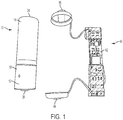
- the reusable battery indicator 40 includes an integrated circuit, which may be incorporated into a printed circuit board (PCB) 42, a first connector 44 that is electrically connected to the PCB 42, and a second connector 46 that is electrically connected to the PCB 42.
- the first connector 44 may be removably and electrically connected to the positive pip 26 to form a positive electrical connection and the second connector 46 may be removably and electrically connected to the end cap 24 to form a negative electrical connection, as illustrated in FIG. 2 .
- the first connector 44 and the second connector 46 may take virtually any physical form that allows the first connector 44 and the second connector 46 to form electrical connections with the battery cell 10 and the PCB 42.
- the first connector 44 and the second connector 46 may take any one or more of the following forms, a magnet, a cup, a sleeve, a tab, a socket, a pin, a washer, a spring connector, a wire loop, or any combination thereof.
- the first connector 44 and the second connector 46 may be formed from virtually any material that transmits analog information, such as electrical information, from the battery cell to the PCB 42.
- the first connector 44 and the second connector 46 may be formed from one or more of the following materials, a metal, a metal alloy, cold-rolled steel, hard drawn ferrous and non-ferrous alloys, high and low carbon steel alloys, post or pre-plated ferrous and non-ferrous alloys, or any combination thereof.
- at least one of the first connector 44 and the second connector 46 may comprise a metal and an insulator.
- the inner surface of the first connector 44 and/or of the second connector 46 may include a non-conductive coating (such as a polymer layer, epoxy or passivate) or an additional insulator ring (paper, phenolic or polymer) to guard against shorting to the battery housing or crimp.
- the integrated circuit receives electrical information, such as amperes or volts from the first connector 44 and from the second connector 46, and the electrical information is used by the integrated circuit to calculate battery characteristic information, such as power or charge level, and the integrated circuit then transmits the battery characteristic information to a receiver, such as a computer, a smart phone, or a personal digital assistant, for use by the consumer.
- a receiver such as a computer, a smart phone, or a personal digital assistant
- the reusable battery indicator 40 allows a consumer to acquire the battery characteristic information without removing the battery cell from an electronic device (or from a package).
- the first connector 44 and the second connector 46 deliver the electrical information to the integrated circuit without interfering with electrical contacts between the battery cell and the electronic device.
- the reusable battery indicator 40 is movable from one battery cell to another battery cell so as to be reused over and over again, thereby reducing the overall cost to a consumer.
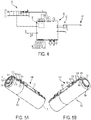
- an integrated circuit 48 that includes an embedded voltage sensor 50 within the integrated circuit 48 that is communicatively connected to the first connector 44 and to the second connector 46.
- the embedded voltage sensor 50 senses analog characteristics of the battery cell, such as amperes and voltage and converts the sensed analog characteristics to digital information.
- the PCB 42 also includes a communication circuit 52.
- An antenna 54 is operatively coupled to the communication circuit 52.
- the communication circuit 52 may comprise one or more of a radio-frequency identification circuit, a Bluetooth® circuit, a Bluetooth® low energy circuit, a Wi-Fi circuit, a Zigbee® circuit, a LORA circuit, and a Z-wave circuit.
- an integrated circuit such as a wireless Bluetooth Low-Energy voltage sensor, may incorporate the analog to digital converter, a microcontroller, a Bluetooth radio, a memory device, and a DC/DC voltage converter.
- a voltage booster 56 is electrically connected to the integrated circuit 48 and the embedded voltage sensor 50.
- the embedded voltage sensor 50 and the voltage booster 56 are capable of reading the open circuit voltage of the battery that may be, for example, less than 1.8 volts.
- the communication circuit 52 may comprise one or more of a thin disc BLE module, a UHF module, or a RF module.
- the integrated circuit 48, the voltage sensor 50, and the communication circuit 52 are all formed on the PCB 42, which is connected to the first connector 44 and the second connector 46.
- the integrated circuit 48, the voltage sensor 50, and the communication circuit 52 may be formed as separate components that are communicatively and operatively connected to one another.
- FIGS. 5A and 5B similar elements are numbered exactly 100 greater than elements numbered in FIGS. 1-4 .
- the battery cell is numbered 10 in FIGS. 1-4 and the battery cell is numbered 110 in FIGS. 5A and 5B .
- any element from any illustrated embodiment may be incorporated into any other illustrated embodiment.
- FIGS. 5A and 5B a second embodiment of the reusable battery indicator 140 is attached to a battery cell 110.
- the reusable battery indicator 140 includes a PCB 142, a first connector 144, and a second connector 146. While the battery cell 110 in FIGS. 5A and 5B is illustrated as a AA size battery, the illustration is not intended to limit the reusable battery indicator 140 to the illustrated battery cell 110. Rather, the reusable battery indicator 140 may be sized and shaped to fit virtually any battery cell, especially those battery cell sizes listed elsewhere in the specification.
- the first connector 144 and the second connector 146 comprise flexible wires 160, 162, respectively.
- the flexible wires 160, 162 may be formed as spring wires (from hard drawn ferrous and non-ferrous spring alloys) that capture the positive battery terminal 126 and the negative battery terminal 124, respectively, to transmit electrical characteristics, such as voltage and amperes, to the integrated circuit formed on the PCB 142.
- the spring wires may be formed of ASTM A228 music wire with re or post nickel plating to enhance conductivity, to reduce contact resistance, and to provide corrosion resistance.
- the flexible wire 160 includes a first end 166, which is connected to a positive terminal 168 on the PCB 142 and a second end 170, which is also connected to the positive terminal 168 on the PCB 142.
- Other embodiments may include single ended wires.
- the flexible wire 160 includes a first leg 172, extending from the first end 166 and a second leg 174 extending from the second end 170.
- the first leg 172 and the second leg 174 are oriented substantially parallel to a longitudinal axis A of the battery cell 110.
- the first leg 172 and the second leg 174 are connected to one another at an end loop 176.
- the end loop 176 lies in a plane that is substantially perpendicular to the longitudinal axis of the battery cell 110.
- the end loop 176 is sized and shaped to fit around the positive terminal 126 of the battery cell 110.
- the flexible wire 160 forms a positive electrical pathway from the positive battery terminal 126 to the positive terminal 168 on the PCB 142.
- the flexible wire 160 may be formed to produce a spring force that biases the flexible wire 160 into the attached position illustrated in FIGS. 5A and 5B , while allowing the flexible wire 160 to be temporarily deformed by a user to remove the reusable battery indicator 140 from the battery cell 110 when desired.
- the flexible wire 162 includes a first end 178, which is connected to a negative terminal 180 on the PCB 142 and a second end 182, which is also connected to the negative terminal 180 on the PCB 142.
- the flexible wire 162 includes a first leg 184, extending from the first end 178 and a second leg 186 extending from the second end 182.
- the first leg 184 and the second leg 186 are oriented substantially parallel to the longitudinal axis A of the battery cell 110.
- the first leg 184 and the second leg 186 are connected to one another at an end loop 188.
- the end loop 188 lies in a plane that is substantially perpendicular to the longitudinal axis of the battery cell 110.
- the end loop 186 is sized and shaped to fit around the negative terminal 124 of the battery cell 110.
- the flexible wire 162 forms a negative electrical pathway from the negative battery terminal 124 to the negative terminal 180 on the PCB 142.
- the flexible wire 162 may be formed to produce a spring force that biases the flexible wire 162 into the attached position illustrated in FIGS. 5A and 5B , while allowing the flexible wire 162 to be temporarily deformed by a user to remove the reusable battery indicator 140 from the battery cell 110 when desired.
- the approximately 90° bends (which may be greater than 90° in other embodiments to mate with a tapered positive terminal) between the first and second legs 172, 174 of the first flexible wire 160 and the end loop 176 and between the first and second legs 184, 186 of the second flexible wire 162 and the end loop 188, create an axial force, which maintains the reusable battery indicator 140 in electrical connection with the battery cell 110.
- one or more of the first flexible wire 160 and the second flexible wire 162 may include a conductive magnet, or the one or more of the first flexible wire 160 and the second flexible wire 162 may be formed from conductive magnetic material, to provide additional retention force between the first flexible wire 160 and the positive terminal 126 and between the second flexible wire 162 and the negative terminal 124.
- first flexible wire 160 and the second flexible wire 162 may be formed as a Kelvin connection, including separate power and sensing terminals, to measure impedance. Additionally, in alternate embodiments, the first flexible wire 160 and the second flexible wire 162 need not be formed as a single continuous wire, but may be formed as multiple wire pieces, for example, two wire pieces that are separated by a small distance in the end loop.
- FIGS. 6A and 6B a third embodiment of a reusable battery indicator 240 is illustrated that includes a mechanical lock and key assembly 290. Unless stated otherwise, any element from any illustrated embodiment may be incorporated into any other illustrated embodiment.
- the reusable battery indicator 240 of FIGS. 6A and 6B includes a PCB 242, a first connector (not illustrated in FIGS. 6A and 6B ), and a second connector 246. While the battery cell 210 in FIGS. 6A and 6B is illustrated as a AA size battery, the illustration is not intended to limit the reusable battery indicator 240 to the illustrated battery cell 210. Rather, the reusable battery indicator 240 may be sized and shaped to fit virtually any battery cell, especially those battery cell sizes listed elsewhere in the specification.
- the first connector and the second connector 246 comprise flexible wires, such as flexible wire 262.
- the flexible wire 262 may be formed as a spring wire that captures the negative battery terminal 224 to transmit electrical characteristics, such as voltage and amperes, to the integrated circuit formed on the PCB 242.
- the flexible wire forming the first connector may be formed as a spring wire that captures the positive terminal to transmit electrical characteristics to the integrated circuit.
- the flexible wire 262 includes a first end 278, which is connected to a negative terminal 280 on the PCB 242 and a second end 282, which is also connected to a negative terminal 280 on the PCB 242.
- the flexible wire 262 includes a first leg 284, extending from the first end 278 and a second leg 286 extending from the second end 282.
- the first leg 284 and the second leg 286 are oriented substantially parallel to the longitudinal axis of the battery cell 210.
- the first leg 284 and the second leg 286 are connected to one another at an end loop 288.
- the end loop 288 lies in a plane that is substantially perpendicular to the longitudinal axis of the battery cell 210.
- the end loop 288 is sized and shaped to fit around the negative battery terminal 224.
- the flexible wire 262 forms a negative electrical pathway from the negative battery terminal 224 to the negative terminal 280 on the PCB 242.
- the flexible wire forming the first connector may include similar or identical features.
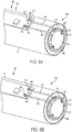
- the mechanical lock and key assembly 290 includes the end loop 288; a lock feature, such as a depression 292 on the negative terminal 224; a key feature, such as a protrusion 294 on the end loop 288; and one or more locking channels 296 formed in the PCB 242.
- the lock feature is a triangular-shaped depression 292 and the key feature is a triangular-shaped protrusion 294.
- the lock feature and the key feature may have other complementary-shapes.
- the male-female relationship may be reversed.
- the first and second ends 278, 282 of the flexible wire 262 are slidable within the locking channels 296. In the unlocked position, which is illustrated in FIG. 6A , the first and second ends 278, 282 are positioned away from the negative terminal 280. As a result, the flexible wire 262 is extended away from the PCB 242. More specifically, the end loop 288 is extended away from the PCB 242, which extends the overall length of the reuslable battery indicator 240 to facilitate attachment of the reusuable battery indicator 240 to the battery cell 210.
- the end loop 288 is pushed towards the PCB 242, which seats the key feature 294 within the lock feature 292, and which moves the first and second ends 278, 282 of the flexible wire 262 into contact with the negative terminal 280, as illustrated in FIG. 6B .
- the mechanical lock and key assembly 290 thus mechanically secures the reusable battery indicator 240 to the battery cell 210 at one end (i.e., at the negative battery terminal 224) while completing a negative electrical circuit between the negative terminal 280 of the PCB and the negative battery terminal 224 through the flexible wire 262.
- the mechanical lock and key assembly 290 prevents the reusable battery indicator 240 from being used on an incorrect battery type (i.e., one that lacks the mechanical lock feature on the negative terminal).
- mechanical lock and key assembly 290 has been described herein as being located on the negative side of the reusable battery indicator 240, the mechanical lock and key assembly 290 could also be located on the positive side of the reusable battery indicator 240 or both the positive and negative sides of the reusable battery indicator 240 could include mechanical lock and key assemblies 290 in other embodiments.
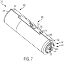
- FIG. 7 a fourth embodiment of a reusable battery indicator 240 is illustrated that includes a mechanical lock and key assembly 290. Unless stated otherwise, any element from any illustrated embodiment may be incorporated into any other illustrated embodiment. In the embodiment of FIG. 7 , like elements have the same reference numerals as the embodiment of FIGS. 6A and 6B for ease of reference, there being only small differences between the two embodiments.
- the reusable battery indicator 240 of FIG. 7 includes a PCB 242, a first connector 244, and a second connector 246. While the battery cell 210 in FIG. 7 is illustrated as a AA size battery, the illustration is not intended to limit the reusable battery indicator 240 to the illustrated battery cell 210. Rather, the reusable battery indicator 240 may be sized and shaped to fit virtually any battery cell, especially those battery cell sizes listed elsewhere in the specification.
- the first connector 244 and the second connector 246 comprise flexible wires, such as flexible wires 260 and 262, respectively .
- the flexible wires 260, 262 may be formed as a spring wires that capture the positive battery terminal 226 and the negative battery terminal 224, respectively, to transmit electrical characteristics, such as voltage and amperes, to the integrated circuit formed on the PCB 242.
- FIG. 7 Further description of the embodiment illustrated in FIG. 7 will be directed to the negative terminal 224 and to the second connector 246. However, the structural features described with respect to the negative terminal 224 and with respect to the second connector 246 apply equally to the positive terminal 226 and to the first connector 244. However, further discussion of such structural features on the positive terminal 226 and on the first connector 244 is omitted in the interest of brevity.
- the flexible wire 262 includes a first end 278, which is connected to a negative terminal 280 on the PCB 242.
- the flexible wire 262 includes a single leg 284, extending from the first end 278.
- the single leg 284 is oriented substantially parallel to the longitudinal axis of the battery cell 210.
- the single leg 284 forms an end loop 288 opposite the first end 278.
- the end loop 288 lies in a plane that is substantially perpendicular to the longitudinal axis of the battery cell 210.
- the end loop 288 is sized and shaped to fit within a recess in the negative battery terminal 224.
- the flexible wire 262 forms a negative electrical pathway from the negative battery terminal 224 to the negative terminal 280 on the PCB 242.
- the flexible wire forming the first connector may include similar or identical features.
- a mechanical lock and key assembly 290 includes the end loop 288, which forms a key feature; and a lock feature, such as the recess 292 on the negative terminal 224.
- the lock feature is the circular-shaped recess 292 and the key feature is the circular-shaped end loop 288.
- the lock feature and the key feature may have other complementary-shapes.
- the male-female relationship may be reversed.
- the mechanical lock and key assembly 290 thus mechanically secures the reusable battery indicator 240 to the battery cell 210 at one end (i.e., at the negative battery terminal 224) while completing a negative electrical circuit between the negative terminal 280 of the PCB and the negative battery terminal 224 through the flexible wire 262 at the other end.
- the mechanical lock and key assembly 290 prevents the reusable battery indicator 240 from being used on an incorrect battery type (i.e., one that lacks the mechanical lock feature on the negative terminal).
- mechanical lock and key assembly 290 has been described herein as being located on the negative side of the reusable battery indicator 240, the mechanical lock and key assembly 290 could also be located on the positive side of the reusable battery indicator 240 or both the positive and negative sides of the reusable battery indicator 240 could include mechanical lock and key assemblies 290 in other embodiments.
- the mechanical lock and key assemblies described herein advantageously stabilize the reusable battery indicator when installed on a battery. More specifically, the mechanical lock and key assemblies prevent the reusable battery indicator from shifting during device use, thereby maintaining positive electrical contact and preventing accidental dislodgement of the reusable battery indicator from the battery.
- FIG. 8 a fifth embodiment of a reusable battery indicator 540 is illustrated and located between two battery cells 510.
- the reusable battery indicator 540 includes a housing 598 that has only a single concave side.
- FIG. 9 illustrates an alternative housing shape.
- the housing 698 is arranged to fit in the void formed by two cylindrical battery cells 610 that are arranged side by side and oriented such that the respective longitudinal axes of the battery cells 610 are parallel to one another.
- a housing having a cross-sectional shape defined by the preceding equation maximizes the usable space between the battery cells.
- a housing having the cross-sectional shape defined above would result in the following housing volumes for the given battery sizes (assuming that the housing length was equal to the battery cell length).
- the housing would have a volume of 526 mm 3 ; and for a AA battery, the housing would have a volume of 1140 mm 3 .
- the housing may have another cross-sectional shapes (e.g., rectangular, trapezoidal, elliptical, semi-circular, and variable prisms that fit into the area between the battery cells as described above).
- a computing device 800 is communicatively connected to the communication circuit in the reusable battery indicator 740.
- the computing device receives information from the communication circuit through wireless signals sent by the antenna in the reusable battery indicator 740.
- the wireless signal may be one or more of a wifi signal, a Bluetooth® signal, a RFID signal, or any other wireless signal.
- the computing device 800 and the reusable battery indicator 740 may communicatively connected by a wired connection.
- the computing device 800 includes a processor 802 and a memory 804.
- the memory 804 may store processor executable instructions that, when executed by the processor 802, cause the processor 802 to detect a wireless communication signal from the reusable battery indicator 740.
- the memory 804 may comprise a non-transitory computer readable medium with the processor executable instructions embedded thereon as an article of manufacture.
- the processor executable instructions may also cause the processor 802 to send wireless signals back to the reusable battery indicator 740 to remotely control battery circuitry through the reusable battery indicator 740. In this manner, the processor 802 may cause the reusable battery indicator 740 to determine battery characteristic data; and to send the battery characteristic data to a user interface, such as a display 806 on the computing device 800.
- the battery characteristic data may comprise at least one of an electrical capacity; a voltage; an impedance, a temperature, a current; an age, a charge/discharge cycle count, and a coulomb count.
- the processor executable instructions when executed by the processor 802, causes the processor 802 to determine at least one of a battery type, a physical location of the battery, and an electrical device that the battery is powering by communicating with the reusuable battery indicator 740.
Landscapes
- Engineering & Computer Science (AREA)
- General Chemical & Material Sciences (AREA)
- Chemical & Material Sciences (AREA)
- Chemical Kinetics & Catalysis (AREA)
- Electrochemistry (AREA)
- Manufacturing & Machinery (AREA)
- Physics & Mathematics (AREA)
- General Physics & Mathematics (AREA)
- Microelectronics & Electronic Packaging (AREA)
- Battery Mounting, Suspending (AREA)
- Secondary Cells (AREA)
- Tests Of Electric Status Of Batteries (AREA)
- Charge And Discharge Circuits For Batteries Or The Like (AREA)
- Primary Cells (AREA)
Claims (15)
- Kombination einer wiederverwendbaren Batterieanzeige (240) und einer Batteriezelle (210), umfassend:eine wiederverwendbare Batterieanzeige (240) umfassend einen Spannungssensor (50), der ausgebildet ist, gemessene analoge Eigenschaften einer Batterie in digitale Informationen zu konvertieren, einen Kommunikationsschaltkreis (52), der mit dem Spannungssensor (50) in Kommunikationsverbindung steht, eine Antenne (54), die mit dem Kommunikationsschaltkreis (52) in Wirkverbindung steht, und einen Verbindungsmechanismus, der einen ersten Verbinder (144) und einen zweiten Verbinder (146) aufweist, die elektrisch mit dem Spannungssensor (50) verbunden sind, wobei der erste Verbinder (144) und der zweite Verbinder (146) dazu ausgebildet sind, lösbar mit einer ersten Batterieklemme bzw. mit einer zweiten Batterieklemme verbunden zu werden, und dadurch eine elektrische Verbindung zwischen dem Spannungssensor (50) und den ersten und zweiten Batterieklemmen bereitzustellen, wobei mindestens einer des ersten Verbinders (144) und des zweiten Verbinders (146) einen Teil einer mechanischen Schloss- und Schlüssel-Baugruppe (290) mit mindestens einer der ersten Batterieklemme und der zweiten Batterieklemme umfasst, undeine Batteriezelle (210), die einen anderen Teil einer mechanischen Schloss- und Schlüssel-Baugruppe (290) umfasst, die auf einer Außenfläche davon angeordnet ist,wobei der Teil der mechanischen Schloss- und Schlüssel-Baugruppe (290) auf der Batteriezelle eines von einer Aussparung und einem Vorsprung umfasst, und der Teil der mechanischen Schloss- und Schlüssel-Baugruppe (290) auf dem mindestens einen des ersten Verbinders (144) und des zweiten Verbinders (146) den anderen der Aussparung und des Vorsprungs umfasst.
- Kombination nach Anspruch 1, wobei der erste Verbinder (144) eine erste mechanische Schloss- und Schlüssel-Baugruppe (290) und der zweite Verbinder (146) eine zweite mechanische Schloss- und Schlüssel-Baugruppe (290) aufweist.
- Kombination nach Anspruch 2, wobei der erste Verbinder (144) eine männliche Verbindung (294) der mechanischen Schloss- und Schlüssel-Baugruppe (290) umfasst und die erste Batterieklemme (224) eine weibliche Verbindung (292) der mechanischen Schloss- und Schlüssel-Baugruppe (290) umfasst.
- Kombination nach Anspruch 3, wobei die männliche Verbindung (294) ein Dreikantschlüssel ist.
- Kombination nach Anspruch 3, wobei die weibliche Verbindung (292) eine dreieckige Aussparung ist.
- Kombination nach Anspruch 1, wobei der Spannungssensor (50) und der Kommunikationsschaltkreis (52) auf einer zweiseitigen Leiterplatte (42) gebildet sind, die ausgebildet ist, zwischen dem ersten Verbinder (144) und dem zweiten Verbinder (146) eingesetzt zu werden.
- Kombination nach Anspruch 1, weiter umfassend ein Gehäuse, wobei der Spannungssensor (50) und der Kommunikationsschaltkreis (52) innerhalb des Gehäuses fixiert sind, wobei das Gehäuse derart dimensioniert und geformt ist, um zwischen zwei zylindrischen Batterien zu passen, die nebeneinander angeordnet sind.
- Kombination nach Anspruch 1, wobei die mechanische Schloss- und Schlüssel-Baugruppe (290) der wiederverwendbaren Batterieanzeige (240) ferner einen gebogenen Kanal (296) mit einem elektrischen Kontakt umfasst, der an einem Ende des gebogenen Kanals (296) gebildet ist.
- Kombination nach Anspruch 1, wobei der Teil der mechanischen Schloss- und Schlüssel-Baugruppe (290) auf der Batterie eine Aussparung (294) umfasst und der Teil der mechanischen Schloss- und Schlüssel-Baugruppe (290) auf der wiederverwendbaren Batterieanzeige einen Vorsprung (292) umfasst.
- Kombination nach Anspruch 1, wobei sich die Aussparung (294) und der Vorsprung (292) in ihrer Form und Größe ergänzen.
- Kombination nach Anspruch 9, wobei die Aussparung (294) entweder dreiecksförmig oder ringförmig ausgebildet ist bzw. der Vorsprung (292) entweder dreiecksförmig oder ringförmig ausgebildet ist.
- Kombination nach Anspruch 9, wobei die Aussparung (294) in einer Batterieklemme angeordnet ist.
- Elektronisches Gerät, umfassend die Kombination nach Anspruch 1, wobei die wiederverwendbare Batterieanzeige (240) innerhalb eines Batteriebehälters des elektronischen Geräts fixiert ist.
- Batteriefernanzeigesystem, wobei das System umfasst:ein Rechengerät (800), unddie Kombination einer wiederverwendbaren Batterieanzeige (240) und einer Batteriezelle (210) nach Anspruch 1.
- System nach Anspruch 14, wobei das Rechengerät (800) einen Prozessor (802) und einen Speicher (804) umfasst, wobei der Speicher (804) eine Softwareroutine speichert, die den Prozessor (802) veranlasst, ein drahtloses Kommunikationssignal von der wiederverwendbaren Batterieanzeige (240) zu detektieren, um Batterieschaltungen über die wiederverwendbare Batterieanzeige (240) fernzusteuern, um charakteristische Daten der Batterie zu bestimmen, und, um die charakteristischen Daten der Batterie zu einer Benutzeroberfläche zu senden.
Applications Claiming Priority (2)
| Application Number | Priority Date | Filing Date | Title |
|---|---|---|---|
| US15/340,773 US11024891B2 (en) | 2016-11-01 | 2016-11-01 | Reusable battery indicator with lock and key mechanism |
| PCT/US2017/059469 WO2018085347A1 (en) | 2016-11-01 | 2017-11-01 | Reusable battery indicator with lock and key mechanism |
Publications (2)
| Publication Number | Publication Date |
|---|---|
| EP3535798A1 EP3535798A1 (de) | 2019-09-11 |
| EP3535798B1 true EP3535798B1 (de) | 2020-09-02 |
Family
ID=60473625
Family Applications (1)
| Application Number | Title | Priority Date | Filing Date |
|---|---|---|---|
| EP17804720.5A Active EP3535798B1 (de) | 2016-11-01 | 2017-11-01 | Wiederverwendbarer indikator für batterie mit schloss- und schlüsselmechanismus |
Country Status (6)
| Country | Link |
|---|---|
| US (1) | US11024891B2 (de) |
| EP (1) | EP3535798B1 (de) |
| JP (1) | JP7326153B2 (de) |
| CN (1) | CN109923728B (de) |
| AU (1) | AU2017355390B2 (de) |
| WO (1) | WO2018085347A1 (de) |
Families Citing this family (17)
| Publication number | Priority date | Publication date | Assignee | Title |
|---|---|---|---|---|
| US9551758B2 (en) | 2012-12-27 | 2017-01-24 | Duracell U.S. Operations, Inc. | Remote sensing of remaining battery capacity using on-battery circuitry |
| US9478850B2 (en) | 2013-05-23 | 2016-10-25 | Duracell U.S. Operations, Inc. | Omni-directional antenna for a cylindrical body |
| US9726763B2 (en) | 2013-06-21 | 2017-08-08 | Duracell U.S. Operations, Inc. | Systems and methods for remotely determining a battery characteristic |
| US9882250B2 (en) | 2014-05-30 | 2018-01-30 | Duracell U.S. Operations, Inc. | Indicator circuit decoupled from a ground plane |
| US10297875B2 (en) | 2015-09-01 | 2019-05-21 | Duracell U.S. Operations, Inc. | Battery including an on-cell indicator |
| US10608293B2 (en) | 2016-11-01 | 2020-03-31 | Duracell U.S. Operations, Inc. | Dual sided reusable battery indicator |
| US10151802B2 (en) | 2016-11-01 | 2018-12-11 | Duracell U.S. Operations, Inc. | Reusable battery indicator with electrical lock and key |
| US10483634B2 (en) | 2016-11-01 | 2019-11-19 | Duracell U.S. Operations, Inc. | Positive battery terminal antenna ground plane |
| US10818979B2 (en) | 2016-11-01 | 2020-10-27 | Duracell U.S. Operations, Inc. | Single sided reusable battery indicator |
| CN109164350A (zh) * | 2018-08-31 | 2019-01-08 | 深圳市亿兆互联技术有限公司 | 一种基于LoRa防偷防落地的电缆监控系统 |
| USD921576S1 (en) * | 2018-12-14 | 2021-06-08 | Duracell U.S. Operations, Inc. | Battery |
| US11265828B2 (en) * | 2019-08-21 | 2022-03-01 | Qualcomm Incorporated | Power allocation for sidelink feedback transmission |
| DE102020108363A1 (de) * | 2020-03-26 | 2021-09-30 | Bayerische Motoren Werke Aktiengesellschaft | Ladeadapter zum Laden einer Fahrzeugbatterie |
| US11837754B2 (en) | 2020-12-30 | 2023-12-05 | Duracell U.S. Operations, Inc. | Magnetic battery cell connection mechanism |
| DE102021115451A1 (de) * | 2021-06-15 | 2022-12-15 | Bayerische Motoren Werke Aktiengesellschaft | Vorrichtung zum Komprimieren zumindest eines Abschnitts einer Energiespeicherzelle sowie System und Verfahren zur elektrischen Sicherheitsprüfung |
| EP4266451A1 (de) * | 2022-04-22 | 2023-10-25 | Dukosi Limited | Verbesserte elektrische batterieanordnung |
| CN219959357U (zh) * | 2023-07-07 | 2023-11-03 | 宁德时代新能源科技股份有限公司 | 电池单体、电池及用电设备 |
Family Cites Families (353)
| Publication number | Priority date | Publication date | Assignee | Title |
|---|---|---|---|---|
| US3354565A (en) | 1966-02-01 | 1967-11-28 | Texas Instruments Inc | Passive information displays |
| CH662773A4 (de) | 1973-05-10 | 1976-02-27 | ||
| FR2290047A1 (fr) | 1974-10-31 | 1976-05-28 | Accumulateurs Fixes | Pile electrique comportant un indicateur visuel de son etat de charge |
| JPS5190035U (de) * | 1975-01-17 | 1976-07-19 | ||
| JPS525581A (en) | 1975-07-02 | 1977-01-17 | Hitachi Ltd | Voltage detector circuit |
| JPS5911911B2 (ja) | 1975-12-01 | 1984-03-19 | シチズン時計株式会社 | デンシコウガクテキヒヨウジタイノクドウホウホウ |
| JPS59107B2 (ja) | 1976-02-09 | 1984-01-05 | シチズン時計株式会社 | エレクトロクロミズム表示装置を備えた携帯用電子装置 |
| JPS5324798A (en) | 1976-08-20 | 1978-03-07 | Sharp Corp | Driving circuit of electrochromic display device |
| US4238554A (en) | 1979-09-04 | 1980-12-09 | Duracell International Inc. | Abuse resistant active metal anode/fluid cathode depolarized cells |
| US4460870A (en) | 1981-07-23 | 1984-07-17 | Curtis Instruments, Inc. | Quiescent voltage sampling battery state of charge meter |
| US4482615A (en) | 1982-09-30 | 1984-11-13 | Power Conversion, Inc. | Lithium anode comprising copper strip in contact with lithium body and lithium-sulfur dioxide battery utilizing same |
| JPS60121931A (ja) | 1983-12-06 | 1985-06-29 | 富士写真フイルム株式会社 | 直流電源装置 |
| US4808497A (en) | 1983-12-28 | 1989-02-28 | Eveready Battery Company | Organic electrolyte for nonaqueous cells |
| US4654280A (en) | 1984-12-27 | 1987-03-31 | Eveready Battery Company | Nonaqueous cell employing a cathode-electrolyte solution containing a boron-containing additive |
| JPS61169781A (ja) | 1985-01-23 | 1986-07-31 | Canon Inc | 画像形成装置 |
| US4759765A (en) | 1986-03-17 | 1988-07-26 | Minnesota Mining And Manufacturing Company | Tissue augmentation device |
| US4860185A (en) | 1987-08-21 | 1989-08-22 | Electronic Research Group, Inc. | Integrated uninterruptible power supply for personal computers |
| JPH02142324A (ja) | 1988-11-19 | 1990-05-31 | Fukuda Denshi Co Ltd | 電池残量表示装置 |
| US5015544A (en) | 1989-02-08 | 1991-05-14 | Strategic Energy Ltd. | Battery with strength indicator |
| US4952330A (en) | 1989-05-25 | 1990-08-28 | Eveready Battery Company, Inc. | Nonaqueous electrolyte |
| JP2667993B2 (ja) | 1989-10-17 | 1997-10-27 | セイコープレシジョン株式会社 | 電池電圧検出装置 |
| US5032825A (en) | 1990-03-02 | 1991-07-16 | Motorola, Inc. | Battery capacity indicator |
| US5219683A (en) | 1990-08-02 | 1993-06-15 | Eveready Battery Company, Inc. | Diol diesters and alkoxyalkylesters as solvents for nonaqueous battery electrolytes |
| CA2054008A1 (en) | 1991-01-31 | 1992-08-01 | Harry R. Huhndorff | Tester for end of cell |
| CA2056139C (en) | 1991-01-31 | 2000-08-01 | Eveready Battery Company, Inc. | Electrochromic thin film state-of-charge detector for on-the-cell application |
| US5654640A (en) | 1991-01-31 | 1997-08-05 | Eveready Battery Company | Cell tester device employing a printed transparent electrically conductive electrode |
| US5737114A (en) | 1991-01-31 | 1998-04-07 | Eveready Battery Company, Inc. | Label having an incorporated electrochromic state-of-charge indicator for an electrochemical cell |
| JPH04334874A (ja) | 1991-05-13 | 1992-11-20 | Sony Corp | 電池式受信機 |
| US5188231A (en) | 1991-05-31 | 1993-02-23 | Duracell Inc. | Battery package with removable voltage indicator means |
| SG66286A1 (en) | 1991-07-16 | 1999-07-20 | Duracell Inc | Battery with integral condition tester |
| CA2072488C (en) | 1991-08-13 | 2002-10-01 | Andrew Webber | Nonaqueous electrolytes |
| US5250905A (en) | 1991-09-24 | 1993-10-05 | Duracell Inc. | Battery with electrochemical tester |
| US5355089A (en) | 1992-07-22 | 1994-10-11 | Duracell Inc. | Moisture barrier for battery with electrochemical tester |
| US5200686A (en) | 1991-10-10 | 1993-04-06 | Motorola, Inc. | Method and apparatus for determining battery type |
| US5290414A (en) | 1992-05-15 | 1994-03-01 | Eveready Battery Company, Inc. | Separator/electrolyte combination for a nonaqueous cell |
| AU662822B2 (en) | 1992-06-01 | 1995-09-14 | Kuraray Co., Ltd. | Separator for alkaline batteries |
| US5231356A (en) * | 1992-06-16 | 1993-07-27 | Robert Parker | Flexible battery tester with a variable length resistive heater |
| JP2727149B2 (ja) | 1992-09-14 | 1998-03-11 | エムアンドシー 株式会社 | バッテリー検査方法 |
| US5434396A (en) | 1992-11-10 | 1995-07-18 | Xicor Inc. | Wireless powering and communication system for communicating data between a host system and a stand-alone device |
| US5438607A (en) | 1992-11-25 | 1995-08-01 | U.S. Monitors, Ltd. | Programmable monitoring system and method |
| DE4241975C1 (de) | 1992-12-12 | 1994-04-21 | Braun Ag | Schaltungsanordnung zur Anzeige des Ladezustands einer Batterie |
| JPH06284170A (ja) | 1993-03-30 | 1994-10-07 | Fujitsu Ten Ltd | 相手先電源の監視機能付き通信装置、および相手先装置 |
| US5389458A (en) | 1993-05-03 | 1995-02-14 | Eveready Battery Company, Inc. | Battery with tester label and method for producing it |
| US5389470A (en) | 1993-05-07 | 1995-02-14 | Parker; Robert | Temperature responsive battery tester |
| AU7398594A (en) | 1993-06-28 | 1995-01-17 | Philip R. Troyk | Remote identification system for containers |
| US5418086A (en) | 1993-08-09 | 1995-05-23 | Eveready Battery Company, Inc. | Battery with coulometric state of charge indicator |
| CA2131358A1 (en) | 1993-09-02 | 1995-03-03 | Jack S. Treger | Battery tester adhesive and system |
| US5514491A (en) | 1993-12-02 | 1996-05-07 | Eveready Battery Company, Inc. | Nonaqueous cell having a lithium iodide-ether electrolyte |
| US5458997A (en) | 1994-08-19 | 1995-10-17 | Medtronic, Inc. | Rebalancing of lithium/silver vandium oxide (Li/SVO) cells for improved performance |
| US5491038A (en) | 1994-08-24 | 1996-02-13 | Duracell Inc. | Contact ring for on-cell battery tester |
| US5578390A (en) | 1994-09-29 | 1996-11-26 | Duracell Inc. | Electrochemical cell label with integrated tester |
| CN1163020A (zh) | 1994-10-04 | 1997-10-22 | 杜拉塞奥公司 | 用于向外部设备报告电池参数的智能电池算法 |
| US5569556A (en) | 1994-12-30 | 1996-10-29 | Display Matrix Corporation | Battery charge indicator |
| US5593794A (en) | 1995-01-23 | 1997-01-14 | Duracell Inc. | Moisture barrier composite film of silicon nitride and fluorocarbon polymer and its use with an on-cell tester for an electrochemical cell |
| US5627472A (en) | 1995-01-26 | 1997-05-06 | Duracell Inc. | Condition tester for a battery |
| US5691083A (en) | 1995-06-07 | 1997-11-25 | Eveready Battery Company, Inc. | Potassium ion additives for voltage control and performance improvement in nonaqueous cells |
| FR2735870B1 (fr) | 1995-06-21 | 1997-09-05 | Sgs Thomson Microelectronics | Mesure numerique relative de haute precision d'une tension |
| JP3384653B2 (ja) * | 1995-07-28 | 2003-03-10 | 三洋電機株式会社 | パック電池 |
| US5640150A (en) | 1995-08-17 | 1997-06-17 | The United States Of America As Represented By The Secretary Of The Army | Resettable state-of-charge indicator for rechargeable batteries |
| US5596278A (en) | 1995-09-08 | 1997-01-21 | Duracell Inc. | Condition tester for a battery |
| US6774685B2 (en) | 1996-05-13 | 2004-08-10 | Micron Technology, Inc. | Radio frequency data communications device |
| JP3351682B2 (ja) | 1996-06-17 | 2002-12-03 | 日野自動車株式会社 | 車載電池の情報伝達装置 |
| US5786106A (en) | 1996-06-24 | 1998-07-28 | Armani; Shane | Battery pack with interchangeable tag-along supplemental feature cartridge particularly for cellular telephones |
| US5959568A (en) | 1996-06-26 | 1999-09-28 | Par Goverment Systems Corporation | Measuring distance |
| US6208235B1 (en) | 1997-03-24 | 2001-03-27 | Checkpoint Systems, Inc. | Apparatus for magnetically decoupling an RFID tag |
| KR100281538B1 (ko) | 1997-12-26 | 2001-02-15 | 윤종용 | 밧데리 사용가능시간 표시기능을 갖는 컴퓨터 |
| US5962158A (en) | 1997-07-21 | 1999-10-05 | Duracell Inc. | End cap assembly for electrochemical cell |
| US6156450A (en) | 1997-07-24 | 2000-12-05 | Eveready Battery Company, Inc. | Battery tester having printed electronic components |
| US6169397B1 (en) | 1997-08-13 | 2001-01-02 | University Technology Corp. | Damped superconducting coil system having a multiturn, planar geometry superconducting coil and shunt resistors electrically connecting successive coil turns |
| US7012504B2 (en) | 2002-04-01 | 2006-03-14 | Micron Technology, Inc. | Wireless identification device, RFID device with push-on/push off switch, and method of manufacturing wireless identification device |
| US6171729B1 (en) | 1998-01-02 | 2001-01-09 | Wilson Greatbatch Ltd | Control of swelling in alkali metal electrochemical cells |
| US6127062A (en) | 1998-03-24 | 2000-10-03 | Duracell Inc | End cap seal assembly for an electrochemical cell |
| US6835491B2 (en) | 1998-04-02 | 2004-12-28 | The Board Of Trustees Of The University Of Illinois | Battery having a built-in controller |
| US6084523A (en) | 1998-07-13 | 2000-07-04 | The United States Of America As Represented By The Secretary Of The Army | Non-intrusive battery status indicator and inventory system |
| US5963012A (en) | 1998-07-13 | 1999-10-05 | Motorola, Inc. | Wireless battery charging system having adaptive parameter sensing |
| US6300004B1 (en) | 1998-08-21 | 2001-10-09 | Eveready Battery Company, Inc. | Battery constructions having reduced collector assembly volume |
| US6265101B1 (en) | 1998-08-21 | 2001-07-24 | Eveready Battery Company, Inc. | Battery constructions having increased internal volume for active components |
| USRE38518E1 (en) | 1998-08-21 | 2004-05-18 | Eveready Battery Company, Inc. | Battery constructions having increased internal volume for active components |
| US6469471B1 (en) | 1998-08-28 | 2002-10-22 | Invensys Energy Systems (Nz) Limited | Battery charge measurement and discharge reserve time prediction technique and apparatus |
| JP2000077928A (ja) | 1998-09-03 | 2000-03-14 | Lintec Corp | ループアンテナ及びデータキャリア |
| GB9820132D0 (en) | 1998-09-16 | 1998-11-11 | Raychem Ltd | Battery over-discharge protection |
| GB9820271D0 (en) | 1998-09-17 | 1998-11-11 | Simoco Int Ltd | A method of and apparatus for monitoring the condition of batteries used by a mobile radio telecommunications fleet |
| DE19944517A1 (de) | 1998-09-18 | 2000-05-25 | C K Electronics Sdn Bhd | Verfahren und Vorrichtung für die Zustandsbestimmung von Automobilbatterien |
| US6014014A (en) | 1998-10-28 | 2000-01-11 | Hewlett-Packard Company | State-of-charge-measurable batteries |
| JP3607105B2 (ja) | 1999-01-26 | 2005-01-05 | 本田技研工業株式会社 | バッテリ残容量検出装置 |
| US6483275B1 (en) | 1999-04-23 | 2002-11-19 | The Board Of Trustees Of The Univesity Of Illinois | Consumer battery having a built-in indicator |
| US6979502B1 (en) | 1999-06-21 | 2005-12-27 | Board Of Trustees Of The University Of Illinois | Battery having a housing for electronic circuitry |
| JP2001022905A (ja) | 1999-07-08 | 2001-01-26 | Hitachi Maxell Ltd | Icカード装置 |
| US6208114B1 (en) | 1999-07-22 | 2001-03-27 | Dallas Semiconductor Corporation | Battery monitoring system with integrated battery holder |
| JP2001093510A (ja) * | 1999-09-28 | 2001-04-06 | Yazaki Corp | バッテリの電源線接続構造 |
| JP2004085580A (ja) | 1999-11-24 | 2004-03-18 | Seiko Epson Corp | 電圧検出装置 |
| GB2359203B (en) | 2000-02-09 | 2004-09-01 | Mitel Semiconductor Ab | CMOS Low battery voltage detector |
| US6775562B1 (en) | 2000-04-17 | 2004-08-10 | Sbc Properties, Lp | Remote battery replacement notification system and method |
| GB2363899A (en) | 2000-06-19 | 2002-01-09 | Ever Ready Ltd | Alkaline electrochemical cells |
| US6627353B1 (en) | 2000-11-08 | 2003-09-30 | Lithium Power Technologies, Inc. | Disposable lithium batteries |
| US7045250B2 (en) | 2000-11-13 | 2006-05-16 | Sanyo Electric Co., Ltd. | Non-aqueous electrolyte battery |
| US6407534B1 (en) | 2001-02-06 | 2002-06-18 | Quallion Llc | Detecting a microcurrent and a microcurrent detecting circuit |
| DE60214833T2 (de) | 2001-03-07 | 2007-09-06 | Acreo Ab | Elektrochromische einrichtung |
| EP1693808A1 (de) | 2001-03-19 | 2006-08-23 | Escort Memory Systems | Verfahren und System zur RFID-Verfolgung |
| EP1377945A4 (de) | 2001-03-19 | 2005-10-26 | Escort Memory Systems | Rfid-verfolgungsverfahren und -system |
| DE10118027B4 (de) | 2001-04-11 | 2005-11-10 | Daimlerchrysler Ag | Batteriemessklemme mit Fremdstartstützpunkt und integrierter Meßsensorik |
| DE10118051B4 (de) | 2001-04-11 | 2005-09-29 | Daimlerchrysler Ag | Batterienmessklemme mit Fremdstartstützpunkt |
| US6730136B2 (en) | 2001-10-01 | 2004-05-04 | Eveready Battery Company, Inc. | Direct addition of beta-aminoenones in organic electrolytes of nonaqueous cells employing solid cathodes |
| US6617072B2 (en) | 2001-11-27 | 2003-09-09 | Ovonic Battery Company, Inc. | Positive active electrode composition with graphite additive |
| WO2003047064A2 (en) | 2001-11-27 | 2003-06-05 | Xsilogy, Inc. | Remote battery monitoring systems and sensors |
| US20050112462A1 (en) | 2003-11-21 | 2005-05-26 | Marple Jack W. | High discharge capacity lithium battery |
| JP2003264009A (ja) * | 2001-12-19 | 2003-09-19 | Midtronics Inc | バッテリテストモジュール |
| US6690171B2 (en) | 2002-03-05 | 2004-02-10 | Chicony Electronics Co., Ltd. | Battery capacity detection device and method |
| FR2837985B1 (fr) | 2002-04-02 | 2004-05-21 | Commissariat Energie Atomique | Antenne receptrice morcelee |
| US6849360B2 (en) | 2002-06-05 | 2005-02-01 | Eveready Battery Company, Inc. | Nonaqueous electrochemical cell with improved energy density |
| US20040048512A1 (en) | 2002-09-11 | 2004-03-11 | Carl Chen | Quick coupler for cylindrical battery terminal |
| AU2003274571A1 (en) | 2002-11-15 | 2004-06-15 | Koninklijke Philips Electronics N.V. | Wireless battery management system |
| US20040189256A1 (en) * | 2003-02-14 | 2004-09-30 | Alcatel | Reusable state of charge indicator |
| JP2004253858A (ja) | 2003-02-18 | 2004-09-09 | Minerva:Kk | Icタグ用のブースタアンテナ装置 |
| US8310201B1 (en) | 2003-05-06 | 2012-11-13 | Cypress Semiconductor Corporation | Battery with electronic compartment |
| US7388350B1 (en) | 2003-05-06 | 2008-06-17 | Cypress Semiconductor Corporation | Battery with electronic compartment |
| EP1629443A4 (de) | 2003-05-23 | 2009-04-01 | Symbol Technologies Inc | Rfid-relaiseinrichtung und verfahren zum weiterleiten eines rfid-signals |
| JP2006528837A (ja) | 2003-07-23 | 2006-12-21 | コーニンクレッカ フィリップス エレクトロニクス エヌ ヴィ | 最小のパターン密度要件を有する半導体技術向けの誘導性および容量性素子 |
| US7067882B2 (en) | 2003-08-28 | 2006-06-27 | Lsi Logic Corporation | High quality factor spiral inductor that utilizes active negative capacitance |
| CN1529182A (zh) | 2003-10-01 | 2004-09-15 | 复旦大学 | 有源射频识别标签卡电池的电量识别与充电方法 |
| WO2005034604A2 (en) | 2003-10-03 | 2005-04-21 | Black & Decker, Inc. | Methods of discharge control for a battery pack of a cordless power tool system, a cordless power tool system and battery pack adapted to provide over-discharge protection and discharge control |
| US6990171B2 (en) | 2003-10-27 | 2006-01-24 | General Electric Company | System and method of determining a user-defined region-of-interest of an imaging subject for x-ray flux management control |
| JP2005141998A (ja) | 2003-11-05 | 2005-06-02 | Sony Corp | リチウム/二硫化鉄一次電池 |
| US8283071B2 (en) | 2003-11-21 | 2012-10-09 | Eveready Battery Company, Inc. | High discharge capacity lithium battery |
| US20050233214A1 (en) | 2003-11-21 | 2005-10-20 | Marple Jack W | High discharge capacity lithium battery |
| US8124274B2 (en) | 2003-11-21 | 2012-02-28 | Eveready Battery Company, Inc. | High discharge capacity lithium battery |
| JP2005158582A (ja) * | 2003-11-27 | 2005-06-16 | Sanyo Electric Co Ltd | 電池ホルダ |
| US7612472B2 (en) | 2004-01-23 | 2009-11-03 | American Power Conversion Corporation | Method and apparatus for monitoring energy storage devices |
| JP4206348B2 (ja) * | 2004-01-27 | 2009-01-07 | 株式会社マキタ | 電池パック及び電動工具 |
| WO2005078673A1 (en) | 2004-02-03 | 2005-08-25 | Sys Technologies, Inc. | Remote battery monitoring system having embedded telesensors |
| US7417599B2 (en) | 2004-02-20 | 2008-08-26 | 3M Innovative Properties Company | Multi-loop antenna for radio frequency identification (RFID) communication |
| US7928059B2 (en) | 2004-02-24 | 2011-04-19 | Wisconsin Alumni Research Foundation | Use of neuropeptides for traumatic cartilage injury |
| US8427109B2 (en) | 2004-04-06 | 2013-04-23 | Chevron Technology Ventures Llc | Battery state of charge reset |
| JP3851639B2 (ja) | 2004-05-14 | 2006-11-29 | 東芝テック株式会社 | 無線タグ読取装置 |
| US7199555B2 (en) | 2004-05-19 | 2007-04-03 | Chien Hung Taiwan Ltd. | Portable emergency vehicle battery charger with microprocessor |
| KR100599795B1 (ko) | 2004-06-29 | 2006-07-12 | 삼성에스디아이 주식회사 | 이차 전지 |
| US7079079B2 (en) | 2004-06-30 | 2006-07-18 | Skycross, Inc. | Low profile compact multi-band meanderline loaded antenna |
| US7772850B2 (en) | 2004-07-12 | 2010-08-10 | Midtronics, Inc. | Wireless battery tester with information encryption means |
| US7521896B2 (en) | 2004-07-20 | 2009-04-21 | Panasonic Ev Energy Co., Ltd. | Abnormal voltage detector apparatus for detecting voltage abnormality in assembled battery |
| US7746242B2 (en) | 2004-07-21 | 2010-06-29 | Honeywell International Inc. | Low battery indicator |
| US8344685B2 (en) | 2004-08-20 | 2013-01-01 | Midtronics, Inc. | System for automatically gathering battery information |
| US20060046153A1 (en) | 2004-08-27 | 2006-03-02 | Andrew Webber | Low temperature Li/FeS2 battery |
| US20060046154A1 (en) | 2004-08-27 | 2006-03-02 | Eveready Battery Company, Inc. | Low temperature Li/FeS2 battery |
| US7510808B2 (en) | 2004-08-27 | 2009-03-31 | Eveready Battery Company, Inc. | Low temperature Li/FeS2 battery |
| US20060047576A1 (en) | 2004-08-30 | 2006-03-02 | Nokia Corporation | Automated memory and accessory purchasing agent for use in a mobile terminal |
| US20060043933A1 (en) | 2004-08-31 | 2006-03-02 | Latinis Gary R | Battery voltage monitor |
| EP1828794B1 (de) | 2004-11-08 | 2018-08-22 | Koninklijke Philips N.V. | Drahtlose batteriestatusverwaltung bei medizinischen geräten |
| JP2006139544A (ja) | 2004-11-12 | 2006-06-01 | Seiko Epson Corp | アクティブrfid−tag |
| US7576517B1 (en) | 2004-11-29 | 2009-08-18 | Data Power Monitoring Corporation | System and method for remote monitoring of battery condition |
| CN100521362C (zh) | 2004-11-30 | 2009-07-29 | 新神户电机株式会社 | 蓄电池单元 |
| US7554294B2 (en) | 2005-01-28 | 2009-06-30 | The Johns Hopkins University | Battery health monitor |
| US20070063895A1 (en) | 2005-02-14 | 2007-03-22 | Visible Assets, Inc. | Low frequency tag and system |
| US20060208898A1 (en) | 2005-03-04 | 2006-09-21 | Intelleflex Corporation | Compact omnidirectional RF system |
| JP3838258B2 (ja) | 2005-03-10 | 2006-10-25 | ソニー株式会社 | バッテリー残量表示方法 |
| US7598880B2 (en) | 2005-03-14 | 2009-10-06 | Liebert Corporation | Wireless battery monitoring system and method |
| JP2006284431A (ja) | 2005-04-01 | 2006-10-19 | Nissan Motor Co Ltd | 二次電池の充電率推定装置 |
| DE102005017682A1 (de) | 2005-04-08 | 2006-10-12 | Varta Microbattery Gmbh | Galvanisches Element |
| JP2006324074A (ja) | 2005-05-18 | 2006-11-30 | Matsushita Electric Ind Co Ltd | 電池に対する情報記録方法及びその装置 |
| US7386404B2 (en) | 2005-05-27 | 2008-06-10 | Savi Technology, Inc. | Method and apparatus for monitoring battery discharge state |
| US7911182B2 (en) | 2005-05-27 | 2011-03-22 | Savi Technology, Inc. | Method and apparatus for detecting a battery voltage |
| US7944368B2 (en) | 2005-08-25 | 2011-05-17 | Gatekeeper Systems, Inc. | Systems and methods for locating and controlling powered vehicles |
| US20090098462A1 (en) | 2005-08-26 | 2009-04-16 | Michiko Fujiwara | Alkaline dry battery |
| FR2891091B1 (fr) | 2005-09-22 | 2008-01-11 | Commissariat Energie Atomique | Antenne plane omnidirectionnelle et procede de fabrication |
| CN2828963Y (zh) | 2005-09-22 | 2006-10-18 | 中达电通股份有限公司 | 无线式电池监控系统 |
| US20070080804A1 (en) | 2005-10-07 | 2007-04-12 | Edwin Hirahara | Systems and methods for enhanced RFID tag performance |
| US7715884B2 (en) | 2005-10-14 | 2010-05-11 | Research In Motion Limited | Mobile device with a smart battery having a battery information profile corresponding to a communication standard |
| US7531989B2 (en) | 2005-11-02 | 2009-05-12 | 02Micro International Ltd. | Battery fuel gauge circuit |
| JP5039980B2 (ja) | 2005-11-14 | 2012-10-03 | 日立ビークルエナジー株式会社 | 二次電池モジュール |
| JP2007171045A (ja) | 2005-12-22 | 2007-07-05 | Panasonic Ev Energy Co Ltd | 電池用制御装置及び二次電池の分極電圧推定方法 |
| JP4892962B2 (ja) | 2005-12-22 | 2012-03-07 | オムロン株式会社 | Rfid用の交信中継装置および交信処理装置 |
| US20070182576A1 (en) | 2006-02-09 | 2007-08-09 | 1673892 Ontario, Inc. | Remote battery monitoring |
| US8026698B2 (en) | 2006-02-09 | 2011-09-27 | Scheucher Karl F | Scalable intelligent power supply system and method |
| CN101948025B (zh) | 2006-02-22 | 2012-05-30 | 东洋制罐株式会社 | 带rfid标签的金属盖及使用其的金属物品 |
| US7331708B2 (en) | 2006-02-23 | 2008-02-19 | National Semiconductor Corporation | Frequency ratio digitizing temperature sensor with linearity correction |
| US20070210924A1 (en) | 2006-03-10 | 2007-09-13 | Wavezero, Inc. | RFID Smart Label with Reduced Layers and Method of Production |
| US7606530B1 (en) | 2006-03-11 | 2009-10-20 | Rockwell Collins, Inc. | RFID system for allowing access to remotely positioned RFID tags |
| US7561050B2 (en) | 2006-06-28 | 2009-07-14 | International Business Machines Corporation | System and method to automate placement of RFID repeaters |
| US20080076029A1 (en) | 2006-07-27 | 2008-03-27 | Bowden William L | Battery |
| US7768236B2 (en) | 2006-07-28 | 2010-08-03 | Panasonic Corporation | Electrical device and battery pack for preventing polarity reversal of battery |
| JP4890993B2 (ja) | 2006-08-02 | 2012-03-07 | 株式会社東海理化電機製作所 | 電動車両の蓄電池装置 |
| CN101126795A (zh) | 2006-08-14 | 2008-02-20 | 英业达股份有限公司 | 电池性能测试系统 |
| ATE429727T1 (de) | 2006-09-29 | 2009-05-15 | W & H Dentalwerk Buermoos Gmbh | Vorrichtung zum laden von akkumulatoren |
| US8162230B2 (en) | 2006-10-17 | 2012-04-24 | Powerid Ltd. | Method and circuit for providing RF isolation of a power source from an antenna and an RFID device employing such a circuit |
| KR101033200B1 (ko) | 2006-10-20 | 2011-05-06 | 주식회사 케이티 | Rfid와 통신망을 이용한 이동체 위치 확인 서비스시스템 및 그 방법 |
| EP1921496A1 (de) | 2006-11-08 | 2008-05-14 | Acreo AB | Elektrochrome Vorrichtung |
| GB0623108D0 (en) | 2006-11-20 | 2006-12-27 | Sericol Ltd | A printable composition |
| US20100030592A1 (en) | 2006-11-30 | 2010-02-04 | Mobilocity Solutions LLC | Transmitting information from a mobile device to a point of sale or point of use |
| JP5164491B2 (ja) | 2006-12-29 | 2013-03-21 | 三洋電機株式会社 | 筒形電池 |
| US20080160392A1 (en) | 2006-12-29 | 2008-07-03 | Shoichi Toya | Cylindrical battery |
| US7741970B2 (en) | 2006-12-31 | 2010-06-22 | At&T Intellectual Property Ii, L.P. | Method and apparatus for a radio frequency identification repeater |
| US8941496B2 (en) | 2007-01-03 | 2015-01-27 | Intelleflex Corporation | Long range RFID device for battery monitoring and systems implementing same |
| US8054160B2 (en) | 2007-03-09 | 2011-11-08 | Innovation Law Group, Ltd. | RFID tag power conservation system and method |
| US8493187B2 (en) | 2007-03-15 | 2013-07-23 | Endotronix, Inc. | Wireless sensor reader |
| US8031054B2 (en) | 2007-03-27 | 2011-10-04 | Round Rock Research, Llc | Multi-antenna element systems and related methods |
| JP4839257B2 (ja) | 2007-04-11 | 2011-12-21 | 株式会社日立製作所 | Rfidタグ |
| DE112008001413T5 (de) | 2007-06-04 | 2010-04-29 | Lear Corp., Southfield | Batteriepol-Anschluss |
| US20080312782A1 (en) | 2007-06-15 | 2008-12-18 | Gene Berdichevsky | Electric vehicle communication interface |
| US20080311795A1 (en) * | 2007-06-15 | 2008-12-18 | Brotto Daniele C | Adapter for cordless power tools |
| US20090009177A1 (en) | 2007-07-02 | 2009-01-08 | Nesscap Co., Ltd. | Voltage monitoring method and circuit for electrical energy storage device |
| US9076331B2 (en) | 2007-07-16 | 2015-07-07 | Crucs Holdings, Llc | System and method to monitor vehicles on a roadway and to control driving restrictions of vehicle drivers |
| JP2009037374A (ja) | 2007-08-01 | 2009-02-19 | Nec Personal Products Co Ltd | 電子タグを備えた電子機器 |
| US8900731B2 (en) | 2007-08-24 | 2014-12-02 | Motorola Solutions, Inc. | Charger system for communication devices using a charger circuit to communicate a charge status to a portable host device |
| US20110023130A1 (en) | 2007-11-26 | 2011-01-27 | Judson Mannon Gudgel | Smart Battery System and Methods of Use |
| JP5179851B2 (ja) | 2007-11-30 | 2013-04-10 | オーツー マイクロ, インコーポレーテッド | 埋め込まれたセルモニタを備えるバッテリパック、電子システム、およびバッテリパックを監視するための方法 |
| BRPI0821073A2 (pt) | 2007-11-30 | 2017-05-23 | Btech Inc | monitores de bateria em rede |
| US8617743B2 (en) | 2007-12-05 | 2013-12-31 | The Gillette Company | Anode balanced lithium-iron disulfide primary cell |
| CA2646925A1 (en) | 2007-12-12 | 2009-06-12 | Westward Industries Ltd. | Battery management system |
| JP2009151953A (ja) | 2007-12-18 | 2009-07-09 | Mitsumi Electric Co Ltd | 電池パック及び電子機器 |
| CN201142022Y (zh) | 2007-12-18 | 2008-10-29 | 瑞德电能股份有限公司 | 电动车辆的电池模块的远程控制系统 |
| TW200933180A (en) | 2008-01-16 | 2009-08-01 | Dhc Specialty Corp | Detachable battery status alarm and its miniature battery status detector |
| US20090214950A1 (en) | 2008-02-22 | 2009-08-27 | Bowden William L | Lithium cell |
| US8164528B2 (en) | 2008-03-26 | 2012-04-24 | Dockon Ag | Self-contained counterpoise compound loop antenna |
| CN201233435Y (zh) | 2008-03-27 | 2009-05-06 | 兰州太格维尔电子有限公司 | 蓄电池剩余容量测试仪 |
| US8076028B2 (en) | 2008-04-16 | 2011-12-13 | The Gillette Company | Lithium cell with cathode including iron disulfide and iron sulfide |
| US7456606B1 (en) | 2008-04-23 | 2008-11-25 | International Business Machines Corporation | Battery label with wireless battery charging circuit |
| US8400297B2 (en) | 2008-05-05 | 2013-03-19 | Round Rock Research, Llc | Power conserving active RFID label |
| US7642942B2 (en) | 2008-05-21 | 2010-01-05 | Honeywell International Inc. | Systems and methods for synthesis of a signal |
| US20090297949A1 (en) | 2008-05-29 | 2009-12-03 | Berkowitz Fred J | Lithium Primary Cells |
| JP5549121B2 (ja) * | 2008-06-17 | 2014-07-16 | 三洋電機株式会社 | 組電池の電圧検出装置及びこれを具えたバッテリシステム |
| US8305034B2 (en) | 2008-07-23 | 2012-11-06 | Lear Corporation | Battery monitoring system |
| JP2010081716A (ja) | 2008-09-25 | 2010-04-08 | Toshiba Corp | 電池情報取得装置 |
| US8529345B2 (en) | 2008-10-02 | 2013-09-10 | Igt | Gaming system including a gaming table with mobile user input devices |
| CN101714647B (zh) | 2008-10-08 | 2012-11-28 | 株式会社牧田 | 电动工具用蓄电池匣以及电动工具 |
| JP5195263B2 (ja) | 2008-10-14 | 2013-05-08 | 凸版印刷株式会社 | 情報伝達媒体管理システム |
| DE102008060668A1 (de) | 2008-12-08 | 2010-06-10 | Auto-Kabel Managementgesellschaft Mbh | Batteriemessklemme |
| KR101009526B1 (ko) | 2008-12-10 | 2011-01-18 | 삼성에스디아이 주식회사 | 배터리 팩 |
| US8417472B2 (en) | 2008-12-19 | 2013-04-09 | 02Micro Inc. | Synchronized data sampling systems and methods |
| JP2010154012A (ja) | 2008-12-24 | 2010-07-08 | Nec Corp | Rfidタグ用識別システム |
| US9086460B2 (en) | 2009-02-05 | 2015-07-21 | Methode Electronics, Inc. | Apparatus and method for monitoring the state of charge of a battery cell |
| KR101023884B1 (ko) | 2009-02-18 | 2011-03-22 | 삼성에스디아이 주식회사 | 배터리팩 |
| PT104482A (pt) | 2009-04-01 | 2010-10-01 | Univ Nova De Lisboa | Método de fabrico e criação de transístores de filme fino electrocrómicos de estrutura lateral ou vertical utilizando substratos vitrocerâmicos, poliméricos, metálicos ou de papel celulósico natural, sintético ou misto funcionalizados ou não funciona |
| KR100928563B1 (ko) * | 2009-04-08 | 2009-11-25 | 태성전장주식회사 | 자동차용 배터리 전류 검출장치 |
| US8852784B2 (en) * | 2009-04-13 | 2014-10-07 | Schneider Electric It Corporation | Self-alignment and shock impact relief battery connector |
| US9076092B2 (en) | 2009-05-08 | 2015-07-07 | Confidex Ltd. | RFID transponder and a method for fabricating the same |
| EP2285068B1 (de) | 2009-08-07 | 2014-06-25 | BlackBerry Limited | Verfahren, mobiles Gerät und computerlesbares Medium für eine mobile Telepräsenz |
| KR20110018488A (ko) | 2009-08-18 | 2011-02-24 | 김창식 | Rfid를 이용한 차량용 배터리 이력관리 시스템 및 그 방법 |
| US8374507B2 (en) | 2009-09-18 | 2013-02-12 | Fluke Corporation | Digital multimeter having remote display with automatic communication binding |
| CN101702792B (zh) | 2009-10-27 | 2011-01-19 | 北京交通大学 | 纯电动公交车电池参数传输装置 |
| US20110104520A1 (en) | 2009-11-02 | 2011-05-05 | Changbum Ahn | Secondary battery and battery pack using the same |
| US20130183568A1 (en) | 2009-11-18 | 2013-07-18 | Susan J. Babinec | Composite separator for electrochemical cell and method for its manufacture |
| US8119286B2 (en) | 2009-11-24 | 2012-02-21 | The Gillette Company | Electrochemical cells with improved separator and electrolyte |
| CN102074722A (zh) | 2009-11-24 | 2011-05-25 | 中兴通讯股份有限公司 | 手持设备电池及手持设备 |
| JP2011113759A (ja) | 2009-11-25 | 2011-06-09 | Diamond Electric Mfg Co Ltd | バッテリー管理装置とバッテリー管理方法 |
| EP2328173B1 (de) | 2009-11-26 | 2016-03-30 | Nxp B.V. | Integrierte Batterie und IC |
| US8390249B2 (en) | 2009-11-30 | 2013-03-05 | Broadcom Corporation | Battery with integrated wireless power receiver and/or RFID |
| US8575939B2 (en) | 2010-01-07 | 2013-11-05 | Paul JANOUSEK | Apparatuses and methods for determining potential energy stored in an electrochemical cell |
| JP5448865B2 (ja) | 2010-01-18 | 2014-03-19 | 三菱重工業株式会社 | 電池システム |
| EP2532040A4 (de) | 2010-02-05 | 2014-10-01 | Alelion Batteries Ab | Batterieanordnung |
| US9425487B2 (en) | 2010-03-03 | 2016-08-23 | Midtronics, Inc. | Monitor for front terminal batteries |
| JP2011203595A (ja) | 2010-03-26 | 2011-10-13 | Fujifilm Corp | 無線通信型カセッテのバッテリ管理装置およびシステム、並びに方法 |
| JP5303528B2 (ja) | 2010-09-16 | 2013-10-02 | カルソニックカンセイ株式会社 | フィルタによるパラメータ推定装置 |
| US20120121943A1 (en) | 2010-09-20 | 2012-05-17 | Fariborz Frankie Roohparvar | Structure and Method for Extending Battery Life |
| US20120086615A1 (en) | 2010-10-12 | 2012-04-12 | John Peter Norair | Method and Apparatus for an Integrated Antenna |
| JP4929389B2 (ja) | 2010-10-14 | 2012-05-09 | 三菱重工業株式会社 | 電池システム |
| US20120183862A1 (en) | 2010-10-21 | 2012-07-19 | Eastman Chemical Company | Battery separator |
| CN103270666B (zh) | 2010-11-02 | 2018-01-30 | 纳维达斯解决方案有限公司 | 用于智能电池管理的无线电池区域网络 |
| JP2012129183A (ja) | 2010-11-26 | 2012-07-05 | Sony Corp | 二次電池セル、電池パック及び電力消費機器 |
| JP5796289B2 (ja) | 2010-11-26 | 2015-10-21 | ソニー株式会社 | 二次電池セル、電池パック及び電力消費機器 |
| CN201927640U (zh) | 2010-12-22 | 2011-08-10 | 中兴通讯股份有限公司 | 一种集成天线的电池和移动终端 |
| CN102097844B (zh) | 2011-01-17 | 2015-08-19 | 余维 | 一种智能电池管理系统 |
| FR2970832B1 (fr) | 2011-01-21 | 2013-08-23 | St Microelectronics Rousset | Indicateur de niveau de batterie par telephone portable |
| US8648752B2 (en) | 2011-02-11 | 2014-02-11 | Pulse Finland Oy | Chassis-excited antenna apparatus and methods |
| JP5633745B2 (ja) | 2011-02-15 | 2014-12-03 | ソニー株式会社 | 電池、電池パック、充電器、および充電システム |
| US9178570B2 (en) | 2011-02-28 | 2015-11-03 | Blackberry Limited | NFC system providing battery power level measurement features and related methods |
| CN102142186B (zh) | 2011-03-01 | 2013-01-09 | 合肥国轩高科动力能源有限公司 | 锂电池组远程监控系统 |
| CN103392133A (zh) | 2011-03-07 | 2013-11-13 | 株式会社日立制作所 | 电池状态推定方法和电池管理系统 |
| US8917214B2 (en) | 2011-03-16 | 2014-12-23 | Avery Dennison Corporation | Dual band RFID device and method of formulation |
| US8761885B2 (en) | 2011-04-29 | 2014-06-24 | Cyberonics, Inc. | Battery life estimation based on voltage depletion rate |
| US9037426B2 (en) | 2011-05-13 | 2015-05-19 | GM Global Technology Operations LLC | Systems and methods for determining cell capacity values in a multi-cell battery |
| CA2837320C (en) | 2011-05-24 | 2020-09-15 | Spireon, Inc. | Battery monitoring system |
| JP5739244B2 (ja) | 2011-06-14 | 2015-06-24 | 矢崎総業株式会社 | 電池状態通知ユニット、バスバモジュール、組電池、及び、電池状態監視システム |
| US9167317B2 (en) | 2011-06-23 | 2015-10-20 | Edward DeMar | Battery monitoring system |
| US20130164567A1 (en) | 2011-06-24 | 2013-06-27 | Seektech, Inc. | Modular battery pack apparatus, systems, and methods |
| US20130069768A1 (en) * | 2011-07-20 | 2013-03-21 | Maitreya Visweswara Madhyastha | Systems, devices, methods and computer-readable storage media that facilitate control of battery-powered devices |
| US9146595B2 (en) | 2011-08-05 | 2015-09-29 | Qualcomm Incorporated | Systems and methods for remotely monitoring or controlling a battery |
| JP5798407B2 (ja) | 2011-08-09 | 2015-10-21 | Fdk株式会社 | 非接触充電対応型二次電池 |
| JP2013038961A (ja) | 2011-08-09 | 2013-02-21 | Panasonic Corp | 電子機器、バッテリおよびバッテリ特定方法 |
| US20140306793A1 (en) | 2011-08-17 | 2014-10-16 | King Abdullah University Of Science And Technology | High Q, Miniaturized LCP-Based Passive Components |
| JP5641006B2 (ja) | 2011-08-31 | 2014-12-17 | ソニー株式会社 | 蓄電装置 |
| US9015513B2 (en) | 2011-11-03 | 2015-04-21 | Vocollect, Inc. | Receiving application specific individual battery adjusted battery use profile data upon loading of work application for managing remaining power of a mobile device |
| CN202308203U (zh) | 2011-11-04 | 2012-07-04 | 广州明美电子有限公司 | 一种轻型电动车的串联锂电池组 |
| JP5403191B2 (ja) | 2011-11-08 | 2014-01-29 | 新神戸電機株式会社 | 蓄電池状態監視システム |
| US20130127611A1 (en) | 2011-11-20 | 2013-05-23 | Battery Marvel, Llc. | Battery marvel 1.0 |
| JP5247874B2 (ja) | 2011-12-06 | 2013-07-24 | パナソニック株式会社 | 蓄電池移転支援装置および蓄電池移転支援方法 |
| CN102544709B (zh) | 2011-12-21 | 2014-07-30 | 上海坤锐电子科技有限公司 | 一种移动支付转接桥的通信距离均衡的转接桥天线 |
| US20130162404A1 (en) | 2011-12-27 | 2013-06-27 | Grant Edward Striemer | Apparatus and Method for Providing Product Information |
| CN102709494A (zh) | 2012-01-04 | 2012-10-03 | 瑞声声学科技(深圳)有限公司 | 电池组件 |
| US20150022148A1 (en) * | 2012-01-23 | 2015-01-22 | Avery Dennison Corporation | Electrochemical cell labels and accessories |
| US9869726B2 (en) | 2012-05-22 | 2018-01-16 | Lawrence Livermore National Security, Llc | Wireless battery management control and monitoring system |
| US9331378B2 (en) | 2012-05-29 | 2016-05-03 | Nxp B.V. | Active load modulation antenna |
| US8905317B1 (en) | 2012-06-07 | 2014-12-09 | Amazon Technologies, Inc. | Co-located passive UHF RFID tag and NFC antenna in compact electronic devices |
| CN202720320U (zh) | 2012-06-08 | 2013-02-06 | 低碳动能开发股份有限公司 | 二次电池主动式监控装置 |
| US20140107853A1 (en) | 2012-06-26 | 2014-04-17 | Black & Decker Inc. | System for enhancing power tools |
| US9619612B2 (en) | 2012-10-15 | 2017-04-11 | Battery Technology Holdings, Llc | Tester for equipment, apparatus, or component with distributed processing function |
| TWI580153B (zh) | 2012-11-13 | 2017-04-21 | 電池監控系統 | |
| US9793616B2 (en) | 2012-11-19 | 2017-10-17 | Apple Inc. | Shared antenna structures for near-field communications and non-near-field communications circuitry |
| US9551758B2 (en) | 2012-12-27 | 2017-01-24 | Duracell U.S. Operations, Inc. | Remote sensing of remaining battery capacity using on-battery circuitry |
| WO2014109272A1 (en) * | 2013-01-11 | 2014-07-17 | Semiconductor Energy Laboratory Co., Ltd. | Electronic device charging method |
| US10870360B2 (en) | 2013-02-12 | 2020-12-22 | Cps Technology Holdings Llc | Battery monitoring network |
| US9013323B2 (en) | 2013-03-15 | 2015-04-21 | Crown Equipment Corporation | Pairing of a battery monitor to a communication device |
| JP2014197805A (ja) | 2013-03-29 | 2014-10-16 | 日立オートモティブシステムズ株式会社 | 電池システム |
| US9083063B2 (en) | 2013-04-03 | 2015-07-14 | The Gillette Company | Electrochemical cell including an integrated circuit |
| US20140302348A1 (en) | 2013-04-03 | 2014-10-09 | The Gillette Company | Electrochemical cell including an integrated circuit |
| KR101450219B1 (ko) * | 2013-04-17 | 2014-10-15 | 주식회사 아이티엠반도체 | 배터리 보호회로 모듈 패키지 |
| US9312575B2 (en) | 2013-05-16 | 2016-04-12 | Midtronics, Inc. | Battery testing system and method |
| US20140342193A1 (en) | 2013-05-17 | 2014-11-20 | Tenergy Corporation | Smart battery system |
| US9673621B2 (en) | 2013-05-23 | 2017-06-06 | Powerful Battery Solutions LLC | Enhanced battery system and method |
| US9478850B2 (en) | 2013-05-23 | 2016-10-25 | Duracell U.S. Operations, Inc. | Omni-directional antenna for a cylindrical body |
| US9726763B2 (en) | 2013-06-21 | 2017-08-08 | Duracell U.S. Operations, Inc. | Systems and methods for remotely determining a battery characteristic |
| US9285430B2 (en) | 2013-08-29 | 2016-03-15 | Ford Global Technologies, Llc | Monitor system and method for stored battery |
| KR101720614B1 (ko) | 2013-08-30 | 2017-03-28 | 삼성에스디아이 주식회사 | 배터리 팩 |
| CN104427037A (zh) * | 2013-09-06 | 2015-03-18 | 中兴通讯股份有限公司 | 一种终端 |
| KR102105170B1 (ko) | 2013-10-24 | 2020-04-24 | 삼성전자주식회사 | 전자장치, 입력장치 및 그 배터리 잔량 결정방법 |
| CN103682482A (zh) | 2013-11-22 | 2014-03-26 | 超威电源有限公司 | 一种无线智能电池 |
| US9543623B2 (en) * | 2013-12-11 | 2017-01-10 | Duracell U.S. Operations, Inc. | Battery condition indicator |
| US9235044B2 (en) | 2014-01-29 | 2016-01-12 | The Gillette Company | Light activated power indicator |
| TWM510009U (zh) | 2014-03-14 | 2015-10-01 | zhi-hong Wu | 無線電池管理系統 |
| KR101493829B1 (ko) * | 2014-03-27 | 2015-02-16 | 삼성에스디아이 주식회사 | 전지 팩 |
| KR102006529B1 (ko) | 2014-04-01 | 2019-08-01 | 센젠 즈룬 드라이빙 테크놀러지 포 일렉트릭 비이클 컴퍼니 리미티드 | 동력배터리 및 셀상태수집장치 |
| US9882250B2 (en) | 2014-05-30 | 2018-01-30 | Duracell U.S. Operations, Inc. | Indicator circuit decoupled from a ground plane |
| US20160277879A1 (en) | 2014-06-10 | 2016-09-22 | Pb Inc | Battery beacon systems and methods of use |
| US9568556B2 (en) | 2014-07-25 | 2017-02-14 | Duracell U.S. Operations, Inc. | Battery state of charge indicator with an auxiliary cell |
| US9823310B2 (en) | 2014-07-25 | 2017-11-21 | Duracell U.S. Operations, Inc. | Battery state of charge indicator with an indicator circuit |
| KR101679913B1 (ko) | 2014-08-12 | 2016-11-25 | 현대자동차주식회사 | 배터리 모듈 |
| US9893390B2 (en) | 2014-08-27 | 2018-02-13 | Duracell U.S. Operations, Inc. | Battery pack including an indicator circuit |
| US9746524B2 (en) | 2014-09-12 | 2017-08-29 | Measurement Ltd. | System and method for monitoring battery status |
| US10102507B2 (en) | 2014-09-25 | 2018-10-16 | Google Llc | Systems and methods to faciliate replacement of depleted batteries |
| KR102229824B1 (ko) | 2014-11-19 | 2021-03-22 | 현대모비스 주식회사 | Ibs 장치 |
| KR20160065613A (ko) | 2014-12-01 | 2016-06-09 | 삼성전자주식회사 | 전압 측정 장치 및 전압 센서 |
| WO2016096011A1 (en) | 2014-12-18 | 2016-06-23 | Widex A/S | System and method for managing replacement parts for a hearing aid |
| US9843220B2 (en) | 2015-01-28 | 2017-12-12 | Motorola Solutions, Inc. | Method and apparatus for operating an internal charger system of a portable electronic device |
| JP6444223B2 (ja) | 2015-03-04 | 2018-12-26 | ルネサスエレクトロニクス株式会社 | 無線送信装置及び無線受信装置 |
| CN104635169A (zh) | 2015-03-04 | 2015-05-20 | 姚锋 | 一种采用蓝牙技术联接智能手机的蓄电池能量监测装置 |
| CN106033803B (zh) | 2015-03-18 | 2019-06-14 | 阿里巴巴集团控股有限公司 | 电池套筒、待寻找设备定位方法及装置 |
| WO2016166735A1 (en) | 2015-04-17 | 2016-10-20 | Gp Batteries International Limited | Smart batteries |
| WO2016172542A1 (en) | 2015-04-24 | 2016-10-27 | Prong, Inc. | Electronic charging system |
| US10297875B2 (en) * | 2015-09-01 | 2019-05-21 | Duracell U.S. Operations, Inc. | Battery including an on-cell indicator |
| US20170062841A1 (en) * | 2015-09-01 | 2017-03-02 | Duracell U.S. Operations, Inc. | Battery including an on-cell indicator |
| US20170092994A1 (en) | 2015-09-25 | 2017-03-30 | Intel Corporation | Smart battery with integrated sensing and electronics |
| CN205160145U (zh) | 2015-11-28 | 2016-04-13 | 惠州市蓝微新源技术有限公司 | 一种基于移动终端监控电池包的系统 |
| CN105337367A (zh) | 2015-11-28 | 2016-02-17 | 惠州市蓝微新源技术有限公司 | 一种基于移动终端监控电池包的系统 |
| US20170176539A1 (en) | 2015-12-16 | 2017-06-22 | Centurylink Intellectual Property Llc | Wireless Capable Battery |
| US10411306B2 (en) | 2016-04-19 | 2019-09-10 | GM Global Technology Operations LLC | Battery module with integrated RF communication and cell sensing board |
| US20170315183A1 (en) | 2016-04-29 | 2017-11-02 | Global Technology Systems, Inc. | Battery pack tester and connected app for bluetooth connected smart device |
| WO2017197383A1 (en) | 2016-05-13 | 2017-11-16 | Schumacher Electric Corporation | Battery state detection system and method |
| CN106405241A (zh) | 2016-08-31 | 2017-02-15 | 天津市畅和科技有限公司 | 一种蓄电池内阻远程检测app监测系统 |
| US10608293B2 (en) | 2016-11-01 | 2020-03-31 | Duracell U.S. Operations, Inc. | Dual sided reusable battery indicator |
| US10483634B2 (en) | 2016-11-01 | 2019-11-19 | Duracell U.S. Operations, Inc. | Positive battery terminal antenna ground plane |
| US10151802B2 (en) * | 2016-11-01 | 2018-12-11 | Duracell U.S. Operations, Inc. | Reusable battery indicator with electrical lock and key |
| US10818979B2 (en) | 2016-11-01 | 2020-10-27 | Duracell U.S. Operations, Inc. | Single sided reusable battery indicator |
| CN106848448A (zh) | 2017-01-12 | 2017-06-13 | 深圳市信宇人科技有限公司 | 基于无线传输方式的锂离子动力电池在线监测方法及其动力电池 |
| CN206804833U (zh) | 2017-04-18 | 2017-12-26 | 巫协森 | 智能电池管理装置 |
| CN107284272A (zh) | 2017-07-10 | 2017-10-24 | 刘玲玲 | 一种动力电池监测装置及方法 |
-
2016
- 2016-11-01 US US15/340,773 patent/US11024891B2/en active Active
-
2017
- 2017-11-01 EP EP17804720.5A patent/EP3535798B1/de active Active
- 2017-11-01 WO PCT/US2017/059469 patent/WO2018085347A1/en not_active Ceased
- 2017-11-01 AU AU2017355390A patent/AU2017355390B2/en active Active
- 2017-11-01 JP JP2019522275A patent/JP7326153B2/ja active Active
- 2017-11-01 CN CN201780067907.1A patent/CN109923728B/zh active Active
Non-Patent Citations (1)
| Title |
|---|
| None * |
Also Published As
| Publication number | Publication date |
|---|---|
| US11024891B2 (en) | 2021-06-01 |
| CN109923728B (zh) | 2023-07-25 |
| AU2017355390B2 (en) | 2023-02-23 |
| JP2019536205A (ja) | 2019-12-12 |
| WO2018085347A1 (en) | 2018-05-11 |
| US20180123176A1 (en) | 2018-05-03 |
| JP7326153B2 (ja) | 2023-08-15 |
| AU2017355390A1 (en) | 2019-05-23 |
| CN109923728A (zh) | 2019-06-21 |
| EP3535798A1 (de) | 2019-09-11 |
Similar Documents
| Publication | Publication Date | Title |
|---|---|---|
| EP3535798B1 (de) | Wiederverwendbarer indikator für batterie mit schloss- und schlüsselmechanismus | |
| US11664539B2 (en) | Dual sided reusable battery indicator | |
| EP3535799B1 (de) | Einseitiger wiederverwendbarer batterieindikator | |
| EP3535800B1 (de) | Wiederverwendbarer indikator für batterie mit elektrischem schloss und schlüssel | |
| US11837754B2 (en) | Magnetic battery cell connection mechanism |
Legal Events
| Date | Code | Title | Description |
|---|---|---|---|
| STAA | Information on the status of an ep patent application or granted ep patent |
Free format text: STATUS: UNKNOWN |
|
| STAA | Information on the status of an ep patent application or granted ep patent |
Free format text: STATUS: THE INTERNATIONAL PUBLICATION HAS BEEN MADE |
|
| PUAI | Public reference made under article 153(3) epc to a published international application that has entered the european phase |
Free format text: ORIGINAL CODE: 0009012 |
|
| STAA | Information on the status of an ep patent application or granted ep patent |
Free format text: STATUS: REQUEST FOR EXAMINATION WAS MADE |
|
| 17P | Request for examination filed |
Effective date: 20190528 |
|
| AK | Designated contracting states |
Kind code of ref document: A1 Designated state(s): AL AT BE BG CH CY CZ DE DK EE ES FI FR GB GR HR HU IE IS IT LI LT LU LV MC MK MT NL NO PL PT RO RS SE SI SK SM TR |
|
| AX | Request for extension of the european patent |
Extension state: BA ME |
|
| DAV | Request for validation of the european patent (deleted) | ||
| DAX | Request for extension of the european patent (deleted) | ||
| GRAP | Despatch of communication of intention to grant a patent |
Free format text: ORIGINAL CODE: EPIDOSNIGR1 |
|
| STAA | Information on the status of an ep patent application or granted ep patent |
Free format text: STATUS: GRANT OF PATENT IS INTENDED |
|
| INTG | Intention to grant announced |
Effective date: 20200320 |
|
| GRAS | Grant fee paid |
Free format text: ORIGINAL CODE: EPIDOSNIGR3 |
|
| GRAA | (expected) grant |
Free format text: ORIGINAL CODE: 0009210 |
|
| STAA | Information on the status of an ep patent application or granted ep patent |
Free format text: STATUS: THE PATENT HAS BEEN GRANTED |
|
| AK | Designated contracting states |
Kind code of ref document: B1 Designated state(s): AL AT BE BG CH CY CZ DE DK EE ES FI FR GB GR HR HU IE IS IT LI LT LU LV MC MK MT NL NO PL PT RO RS SE SI SK SM TR |
|
| REG | Reference to a national code |
Ref country code: GB Ref legal event code: FG4D |
|
| REG | Reference to a national code |
Ref country code: AT Ref legal event code: REF Ref document number: 1309865 Country of ref document: AT Kind code of ref document: T Effective date: 20200915 Ref country code: CH Ref legal event code: EP |
|
| REG | Reference to a national code |
Ref country code: DE Ref legal event code: R096 Ref document number: 602017022978 Country of ref document: DE |
|
| REG | Reference to a national code |
Ref country code: IE Ref legal event code: FG4D |
|
| REG | Reference to a national code |
Ref country code: LT Ref legal event code: MG4D |
|
| PG25 | Lapsed in a contracting state [announced via postgrant information from national office to epo] |
Ref country code: FI Free format text: LAPSE BECAUSE OF FAILURE TO SUBMIT A TRANSLATION OF THE DESCRIPTION OR TO PAY THE FEE WITHIN THE PRESCRIBED TIME-LIMIT Effective date: 20200902 Ref country code: NO Free format text: LAPSE BECAUSE OF FAILURE TO SUBMIT A TRANSLATION OF THE DESCRIPTION OR TO PAY THE FEE WITHIN THE PRESCRIBED TIME-LIMIT Effective date: 20201202 Ref country code: GR Free format text: LAPSE BECAUSE OF FAILURE TO SUBMIT A TRANSLATION OF THE DESCRIPTION OR TO PAY THE FEE WITHIN THE PRESCRIBED TIME-LIMIT Effective date: 20201203 Ref country code: BG Free format text: LAPSE BECAUSE OF FAILURE TO SUBMIT A TRANSLATION OF THE DESCRIPTION OR TO PAY THE FEE WITHIN THE PRESCRIBED TIME-LIMIT Effective date: 20201202 Ref country code: SE Free format text: LAPSE BECAUSE OF FAILURE TO SUBMIT A TRANSLATION OF THE DESCRIPTION OR TO PAY THE FEE WITHIN THE PRESCRIBED TIME-LIMIT Effective date: 20200902 Ref country code: LT Free format text: LAPSE BECAUSE OF FAILURE TO SUBMIT A TRANSLATION OF THE DESCRIPTION OR TO PAY THE FEE WITHIN THE PRESCRIBED TIME-LIMIT Effective date: 20200902 Ref country code: HR Free format text: LAPSE BECAUSE OF FAILURE TO SUBMIT A TRANSLATION OF THE DESCRIPTION OR TO PAY THE FEE WITHIN THE PRESCRIBED TIME-LIMIT Effective date: 20200902 |
|
| REG | Reference to a national code |
Ref country code: NL Ref legal event code: MP Effective date: 20200902 |
|
| REG | Reference to a national code |
Ref country code: AT Ref legal event code: MK05 Ref document number: 1309865 Country of ref document: AT Kind code of ref document: T Effective date: 20200902 |
|
| PG25 | Lapsed in a contracting state [announced via postgrant information from national office to epo] |
Ref country code: PL Free format text: LAPSE BECAUSE OF FAILURE TO SUBMIT A TRANSLATION OF THE DESCRIPTION OR TO PAY THE FEE WITHIN THE PRESCRIBED TIME-LIMIT Effective date: 20200902 Ref country code: RS Free format text: LAPSE BECAUSE OF FAILURE TO SUBMIT A TRANSLATION OF THE DESCRIPTION OR TO PAY THE FEE WITHIN THE PRESCRIBED TIME-LIMIT Effective date: 20200902 Ref country code: LV Free format text: LAPSE BECAUSE OF FAILURE TO SUBMIT A TRANSLATION OF THE DESCRIPTION OR TO PAY THE FEE WITHIN THE PRESCRIBED TIME-LIMIT Effective date: 20200902 |
|
| PG25 | Lapsed in a contracting state [announced via postgrant information from national office to epo] |
Ref country code: SM Free format text: LAPSE BECAUSE OF FAILURE TO SUBMIT A TRANSLATION OF THE DESCRIPTION OR TO PAY THE FEE WITHIN THE PRESCRIBED TIME-LIMIT Effective date: 20200902 Ref country code: CZ Free format text: LAPSE BECAUSE OF FAILURE TO SUBMIT A TRANSLATION OF THE DESCRIPTION OR TO PAY THE FEE WITHIN THE PRESCRIBED TIME-LIMIT Effective date: 20200902 Ref country code: PT Free format text: LAPSE BECAUSE OF FAILURE TO SUBMIT A TRANSLATION OF THE DESCRIPTION OR TO PAY THE FEE WITHIN THE PRESCRIBED TIME-LIMIT Effective date: 20210104 Ref country code: RO Free format text: LAPSE BECAUSE OF FAILURE TO SUBMIT A TRANSLATION OF THE DESCRIPTION OR TO PAY THE FEE WITHIN THE PRESCRIBED TIME-LIMIT Effective date: 20200902 Ref country code: EE Free format text: LAPSE BECAUSE OF FAILURE TO SUBMIT A TRANSLATION OF THE DESCRIPTION OR TO PAY THE FEE WITHIN THE PRESCRIBED TIME-LIMIT Effective date: 20200902 |
|
| PG25 | Lapsed in a contracting state [announced via postgrant information from national office to epo] |
Ref country code: IS Free format text: LAPSE BECAUSE OF FAILURE TO SUBMIT A TRANSLATION OF THE DESCRIPTION OR TO PAY THE FEE WITHIN THE PRESCRIBED TIME-LIMIT Effective date: 20210102 Ref country code: ES Free format text: LAPSE BECAUSE OF FAILURE TO SUBMIT A TRANSLATION OF THE DESCRIPTION OR TO PAY THE FEE WITHIN THE PRESCRIBED TIME-LIMIT Effective date: 20200902 Ref country code: AL Free format text: LAPSE BECAUSE OF FAILURE TO SUBMIT A TRANSLATION OF THE DESCRIPTION OR TO PAY THE FEE WITHIN THE PRESCRIBED TIME-LIMIT Effective date: 20200902 Ref country code: AT Free format text: LAPSE BECAUSE OF FAILURE TO SUBMIT A TRANSLATION OF THE DESCRIPTION OR TO PAY THE FEE WITHIN THE PRESCRIBED TIME-LIMIT Effective date: 20200902 |
|
| REG | Reference to a national code |
Ref country code: DE Ref legal event code: R097 Ref document number: 602017022978 Country of ref document: DE |
|
| PG25 | Lapsed in a contracting state [announced via postgrant information from national office to epo] |
Ref country code: MC Free format text: LAPSE BECAUSE OF FAILURE TO SUBMIT A TRANSLATION OF THE DESCRIPTION OR TO PAY THE FEE WITHIN THE PRESCRIBED TIME-LIMIT Effective date: 20200902 Ref country code: SK Free format text: LAPSE BECAUSE OF FAILURE TO SUBMIT A TRANSLATION OF THE DESCRIPTION OR TO PAY THE FEE WITHIN THE PRESCRIBED TIME-LIMIT Effective date: 20200902 |
|
| REG | Reference to a national code |
Ref country code: CH Ref legal event code: PL |
|
| PLBE | No opposition filed within time limit |
Free format text: ORIGINAL CODE: 0009261 |
|
| STAA | Information on the status of an ep patent application or granted ep patent |
Free format text: STATUS: NO OPPOSITION FILED WITHIN TIME LIMIT |
|
| PG25 | Lapsed in a contracting state [announced via postgrant information from national office to epo] |
Ref country code: LU Free format text: LAPSE BECAUSE OF NON-PAYMENT OF DUE FEES Effective date: 20201101 |
|
| 26N | No opposition filed |
Effective date: 20210603 |
|
| PG25 | Lapsed in a contracting state [announced via postgrant information from national office to epo] |
Ref country code: SI Free format text: LAPSE BECAUSE OF FAILURE TO SUBMIT A TRANSLATION OF THE DESCRIPTION OR TO PAY THE FEE WITHIN THE PRESCRIBED TIME-LIMIT Effective date: 20200902 Ref country code: DK Free format text: LAPSE BECAUSE OF FAILURE TO SUBMIT A TRANSLATION OF THE DESCRIPTION OR TO PAY THE FEE WITHIN THE PRESCRIBED TIME-LIMIT Effective date: 20200902 Ref country code: LI Free format text: LAPSE BECAUSE OF NON-PAYMENT OF DUE FEES Effective date: 20201130 Ref country code: CH Free format text: LAPSE BECAUSE OF NON-PAYMENT OF DUE FEES Effective date: 20201130 |
|
| PG25 | Lapsed in a contracting state [announced via postgrant information from national office to epo] |
Ref country code: IT Free format text: LAPSE BECAUSE OF FAILURE TO SUBMIT A TRANSLATION OF THE DESCRIPTION OR TO PAY THE FEE WITHIN THE PRESCRIBED TIME-LIMIT Effective date: 20200902 Ref country code: IE Free format text: LAPSE BECAUSE OF NON-PAYMENT OF DUE FEES Effective date: 20201101 |
|
| PG25 | Lapsed in a contracting state [announced via postgrant information from national office to epo] |
Ref country code: TR Free format text: LAPSE BECAUSE OF FAILURE TO SUBMIT A TRANSLATION OF THE DESCRIPTION OR TO PAY THE FEE WITHIN THE PRESCRIBED TIME-LIMIT Effective date: 20200902 Ref country code: MT Free format text: LAPSE BECAUSE OF FAILURE TO SUBMIT A TRANSLATION OF THE DESCRIPTION OR TO PAY THE FEE WITHIN THE PRESCRIBED TIME-LIMIT Effective date: 20200902 Ref country code: CY Free format text: LAPSE BECAUSE OF FAILURE TO SUBMIT A TRANSLATION OF THE DESCRIPTION OR TO PAY THE FEE WITHIN THE PRESCRIBED TIME-LIMIT Effective date: 20200902 |
|
| PG25 | Lapsed in a contracting state [announced via postgrant information from national office to epo] |
Ref country code: MK Free format text: LAPSE BECAUSE OF FAILURE TO SUBMIT A TRANSLATION OF THE DESCRIPTION OR TO PAY THE FEE WITHIN THE PRESCRIBED TIME-LIMIT Effective date: 20200902 |
|
| P01 | Opt-out of the competence of the unified patent court (upc) registered |
Effective date: 20230524 |
|
| PG25 | Lapsed in a contracting state [announced via postgrant information from national office to epo] |
Ref country code: NL Free format text: LAPSE BECAUSE OF NON-PAYMENT OF DUE FEES Effective date: 20200923 |
|
| REG | Reference to a national code |
Ref country code: DE Ref legal event code: R082 Ref document number: 602017022978 Country of ref document: DE Representative=s name: EISENFUEHR SPEISER PATENTANWAELTE RECHTSANWAEL, DE |
|
| PGFP | Annual fee paid to national office [announced via postgrant information from national office to epo] |
Ref country code: BE Payment date: 20250917 Year of fee payment: 9 Ref country code: GB Payment date: 20250911 Year of fee payment: 9 |
|
| PGFP | Annual fee paid to national office [announced via postgrant information from national office to epo] |
Ref country code: FR Payment date: 20250908 Year of fee payment: 9 |
|
| PGFP | Annual fee paid to national office [announced via postgrant information from national office to epo] |
Ref country code: DE Payment date: 20250910 Year of fee payment: 9 |