EP3325078B1 - Sondes urétérales et vésicales - Google Patents
Sondes urétérales et vésicales Download PDFInfo
- Publication number
- EP3325078B1 EP3325078B1 EP16828458.6A EP16828458A EP3325078B1 EP 3325078 B1 EP3325078 B1 EP 3325078B1 EP 16828458 A EP16828458 A EP 16828458A EP 3325078 B1 EP3325078 B1 EP 3325078B1
- Authority
- EP
- European Patent Office
- Prior art keywords
- catheter
- bladder
- kidney
- coil
- drainage lumen
- Prior art date
- Legal status (The legal status is an assumption and is not a legal conclusion. Google has not performed a legal analysis and makes no representation as to the accuracy of the status listed.)
- Active
Links
- 210000003734 kidney Anatomy 0.000 claims description 167
- 230000014759 maintenance of location Effects 0.000 claims description 127
- 239000012530 fluid Substances 0.000 claims description 109
- 210000000626 ureter Anatomy 0.000 claims description 92
- 210000003708 urethra Anatomy 0.000 claims description 26
- 210000001635 urinary tract Anatomy 0.000 claims description 17
- 238000003780 insertion Methods 0.000 claims description 15
- 230000037431 insertion Effects 0.000 claims description 15
- 210000003932 urinary bladder Anatomy 0.000 description 190
- 210000002700 urine Anatomy 0.000 description 179
- DDRJAANPRJIHGJ-UHFFFAOYSA-N creatinine Chemical compound CN1CC(=O)NC1=N DDRJAANPRJIHGJ-UHFFFAOYSA-N 0.000 description 58
- 210000000244 kidney pelvis Anatomy 0.000 description 55
- 229940109239 creatinine Drugs 0.000 description 29
- 210000005239 tubule Anatomy 0.000 description 29
- 241001465754 Metazoa Species 0.000 description 25
- 238000000034 method Methods 0.000 description 25
- 206010020565 Hyperaemia Diseases 0.000 description 20
- DGAQECJNVWCQMB-PUAWFVPOSA-M Ilexoside XXIX Chemical compound C[C@@H]1CC[C@@]2(CC[C@@]3(C(=CC[C@H]4[C@]3(CC[C@@H]5[C@@]4(CC[C@@H](C5(C)C)OS(=O)(=O)[O-])C)C)[C@@H]2[C@]1(C)O)C)C(=O)O[C@H]6[C@@H]([C@H]([C@@H]([C@H](O6)CO)O)O)O.[Na+] DGAQECJNVWCQMB-PUAWFVPOSA-M 0.000 description 20
- 238000004891 communication Methods 0.000 description 20
- 230000009467 reduction Effects 0.000 description 20
- 239000011734 sodium Substances 0.000 description 20
- 229910052708 sodium Inorganic materials 0.000 description 20
- 238000011282 treatment Methods 0.000 description 20
- 230000009724 venous congestion Effects 0.000 description 20
- 241000282898 Sus scrofa Species 0.000 description 18
- 230000005484 gravity Effects 0.000 description 17
- 210000001631 vena cava inferior Anatomy 0.000 description 17
- 208000009304 Acute Kidney Injury Diseases 0.000 description 16
- 208000033626 Renal failure acute Diseases 0.000 description 16
- 201000011040 acute kidney failure Diseases 0.000 description 16
- 210000002966 serum Anatomy 0.000 description 16
- 238000002560 therapeutic procedure Methods 0.000 description 15
- 210000001519 tissue Anatomy 0.000 description 15
- 210000004369 blood Anatomy 0.000 description 14
- 239000008280 blood Substances 0.000 description 14
- 238000001914 filtration Methods 0.000 description 14
- 230000001965 increasing effect Effects 0.000 description 14
- 230000000638 stimulation Effects 0.000 description 14
- XLYOFNOQVPJJNP-UHFFFAOYSA-N water Substances O XLYOFNOQVPJJNP-UHFFFAOYSA-N 0.000 description 14
- 230000006378 damage Effects 0.000 description 13
- 210000000885 nephron Anatomy 0.000 description 13
- 230000001939 inductive effect Effects 0.000 description 12
- 239000000463 material Substances 0.000 description 12
- 210000001736 capillary Anatomy 0.000 description 11
- 230000007423 decrease Effects 0.000 description 11
- 210000004276 hyalin Anatomy 0.000 description 10
- 206010019280 Heart failures Diseases 0.000 description 9
- 102000013519 Lipocalin-2 Human genes 0.000 description 9
- 108010051335 Lipocalin-2 Proteins 0.000 description 9
- 230000002706 hydrostatic effect Effects 0.000 description 9
- 238000005259 measurement Methods 0.000 description 9
- 210000000056 organ Anatomy 0.000 description 9
- 102100034459 Hepatitis A virus cellular receptor 1 Human genes 0.000 description 8
- 101710185991 Hepatitis A virus cellular receptor 1 homolog Proteins 0.000 description 8
- 230000000694 effects Effects 0.000 description 8
- 208000014674 injury Diseases 0.000 description 8
- 206010021143 Hypoxia Diseases 0.000 description 7
- 208000027418 Wounds and injury Diseases 0.000 description 7
- 238000010521 absorption reaction Methods 0.000 description 7
- 210000002565 arteriole Anatomy 0.000 description 7
- 230000007850 degeneration Effects 0.000 description 7
- 238000011156 evaluation Methods 0.000 description 7
- 238000002474 experimental method Methods 0.000 description 7
- FAPWRFPIFSIZLT-UHFFFAOYSA-M Sodium chloride Chemical compound [Na+].[Cl-] FAPWRFPIFSIZLT-UHFFFAOYSA-M 0.000 description 6
- 238000000576 coating method Methods 0.000 description 6
- 230000003907 kidney function Effects 0.000 description 6
- 238000004519 manufacturing process Methods 0.000 description 6
- 210000005036 nerve Anatomy 0.000 description 6
- 230000010412 perfusion Effects 0.000 description 6
- 230000001225 therapeutic effect Effects 0.000 description 6
- 230000002485 urinary effect Effects 0.000 description 6
- 206010016803 Fluid overload Diseases 0.000 description 5
- XUIMIQQOPSSXEZ-UHFFFAOYSA-N Silicon Chemical compound [Si] XUIMIQQOPSSXEZ-UHFFFAOYSA-N 0.000 description 5
- 230000005779 cell damage Effects 0.000 description 5
- 230000003247 decreasing effect Effects 0.000 description 5
- 230000006870 function Effects 0.000 description 5
- 230000000004 hemodynamic effect Effects 0.000 description 5
- 230000007954 hypoxia Effects 0.000 description 5
- 210000003205 muscle Anatomy 0.000 description 5
- 210000005084 renal tissue Anatomy 0.000 description 5
- 229910052710 silicon Inorganic materials 0.000 description 5
- 239000010703 silicon Substances 0.000 description 5
- 230000007704 transition Effects 0.000 description 5
- 239000002699 waste material Substances 0.000 description 5
- 206010016807 Fluid retention Diseases 0.000 description 4
- 230000009056 active transport Effects 0.000 description 4
- 238000004458 analytical method Methods 0.000 description 4
- 210000003484 anatomy Anatomy 0.000 description 4
- 230000003466 anti-cipated effect Effects 0.000 description 4
- 230000008901 benefit Effects 0.000 description 4
- 230000017531 blood circulation Effects 0.000 description 4
- 239000011248 coating agent Substances 0.000 description 4
- 201000010099 disease Diseases 0.000 description 4
- 208000037265 diseases, disorders, signs and symptoms Diseases 0.000 description 4
- 210000003743 erythrocyte Anatomy 0.000 description 4
- 239000000706 filtrate Substances 0.000 description 4
- 238000010562 histological examination Methods 0.000 description 4
- 230000003902 lesion Effects 0.000 description 4
- 210000000210 loop of henle Anatomy 0.000 description 4
- HLXZNVUGXRDIFK-UHFFFAOYSA-N nickel titanium Chemical compound [Ti].[Ti].[Ti].[Ti].[Ti].[Ti].[Ti].[Ti].[Ti].[Ti].[Ti].[Ni].[Ni].[Ni].[Ni].[Ni].[Ni].[Ni].[Ni].[Ni].[Ni].[Ni].[Ni].[Ni].[Ni] HLXZNVUGXRDIFK-UHFFFAOYSA-N 0.000 description 4
- 229910001000 nickel titanium Inorganic materials 0.000 description 4
- 230000036961 partial effect Effects 0.000 description 4
- SONNWYBIRXJNDC-VIFPVBQESA-N phenylephrine Chemical compound CNC[C@H](O)C1=CC=CC(O)=C1 SONNWYBIRXJNDC-VIFPVBQESA-N 0.000 description 4
- 229960001802 phenylephrine Drugs 0.000 description 4
- 229920001343 polytetrafluoroethylene Polymers 0.000 description 4
- 239000004810 polytetrafluoroethylene Substances 0.000 description 4
- 239000011148 porous material Substances 0.000 description 4
- 230000008569 process Effects 0.000 description 4
- 102000004169 proteins and genes Human genes 0.000 description 4
- 108090000623 proteins and genes Proteins 0.000 description 4
- 230000002829 reductive effect Effects 0.000 description 4
- 210000002796 renal vein Anatomy 0.000 description 4
- 239000012781 shape memory material Substances 0.000 description 4
- 238000012800 visualization Methods 0.000 description 4
- 206010007556 Cardiac failure acute Diseases 0.000 description 3
- 208000004990 Cardiorenal syndrome Diseases 0.000 description 3
- 238000000429 assembly Methods 0.000 description 3
- 230000000712 assembly Effects 0.000 description 3
- 230000008859 change Effects 0.000 description 3
- 201000000523 end stage renal failure Diseases 0.000 description 3
- 210000002216 heart Anatomy 0.000 description 3
- 230000005764 inhibitory process Effects 0.000 description 3
- 230000000670 limiting effect Effects 0.000 description 3
- 230000033001 locomotion Effects 0.000 description 3
- 230000001926 lymphatic effect Effects 0.000 description 3
- 230000003204 osmotic effect Effects 0.000 description 3
- 230000002572 peristaltic effect Effects 0.000 description 3
- 238000012552 review Methods 0.000 description 3
- 239000011780 sodium chloride Substances 0.000 description 3
- 238000012360 testing method Methods 0.000 description 3
- 230000000007 visual effect Effects 0.000 description 3
- 230000002407 ATP formation Effects 0.000 description 2
- RTZKZFJDLAIYFH-UHFFFAOYSA-N Diethyl ether Chemical compound CCOCC RTZKZFJDLAIYFH-UHFFFAOYSA-N 0.000 description 2
- WSFSSNUMVMOOMR-UHFFFAOYSA-N Formaldehyde Chemical compound O=C WSFSSNUMVMOOMR-UHFFFAOYSA-N 0.000 description 2
- 206010020772 Hypertension Diseases 0.000 description 2
- 208000004880 Polyuria Diseases 0.000 description 2
- 206010040047 Sepsis Diseases 0.000 description 2
- 229920006362 Teflon® Polymers 0.000 description 2
- 210000000683 abdominal cavity Anatomy 0.000 description 2
- 230000004913 activation Effects 0.000 description 2
- 239000000654 additive Substances 0.000 description 2
- 238000004873 anchoring Methods 0.000 description 2
- 238000005452 bending Methods 0.000 description 2
- 229920000249 biocompatible polymer Polymers 0.000 description 2
- 230000005540 biological transmission Effects 0.000 description 2
- 239000000090 biomarker Substances 0.000 description 2
- 230000036772 blood pressure Effects 0.000 description 2
- 210000004204 blood vessel Anatomy 0.000 description 2
- 210000002665 bowman capsule Anatomy 0.000 description 2
- 230000000747 cardiac effect Effects 0.000 description 2
- 208000020832 chronic kidney disease Diseases 0.000 description 2
- 230000008602 contraction Effects 0.000 description 2
- 230000035619 diuresis Effects 0.000 description 2
- 230000029142 excretion Effects 0.000 description 2
- 210000003722 extracellular fluid Anatomy 0.000 description 2
- 210000003414 extremity Anatomy 0.000 description 2
- 208000018875 hypoxemia Diseases 0.000 description 2
- 230000006872 improvement Effects 0.000 description 2
- 238000005304 joining Methods 0.000 description 2
- 239000004816 latex Substances 0.000 description 2
- 229920000126 latex Polymers 0.000 description 2
- 238000013507 mapping Methods 0.000 description 2
- 230000001404 mediated effect Effects 0.000 description 2
- 239000000203 mixture Substances 0.000 description 2
- 238000012544 monitoring process Methods 0.000 description 2
- 230000008855 peristalsis Effects 0.000 description 2
- 229920001296 polysiloxane Polymers 0.000 description 2
- -1 polytetrafluoroethylene Polymers 0.000 description 2
- 229920002635 polyurethane Polymers 0.000 description 2
- 239000004814 polyurethane Substances 0.000 description 2
- 229920000915 polyvinyl chloride Polymers 0.000 description 2
- 239000004800 polyvinyl chloride Substances 0.000 description 2
- 238000012545 processing Methods 0.000 description 2
- 210000001147 pulmonary artery Anatomy 0.000 description 2
- 230000028327 secretion Effects 0.000 description 2
- 230000004936 stimulating effect Effects 0.000 description 2
- 239000013589 supplement Substances 0.000 description 2
- 230000010024 tubular injury Effects 0.000 description 2
- 208000037978 tubular injury Diseases 0.000 description 2
- 206010058808 Abdominal compartment syndrome Diseases 0.000 description 1
- 102000009027 Albumins Human genes 0.000 description 1
- 108010088751 Albumins Proteins 0.000 description 1
- 206010002091 Anaesthesia Diseases 0.000 description 1
- 102000008873 Angiotensin II receptor Human genes 0.000 description 1
- 108050000824 Angiotensin II receptor Proteins 0.000 description 1
- OYPRJOBELJOOCE-UHFFFAOYSA-N Calcium Chemical compound [Ca] OYPRJOBELJOOCE-UHFFFAOYSA-N 0.000 description 1
- 206010007559 Cardiac failure congestive Diseases 0.000 description 1
- 229920000742 Cotton Polymers 0.000 description 1
- 208000028399 Critical Illness Diseases 0.000 description 1
- 208000000059 Dyspnea Diseases 0.000 description 1
- 206010013975 Dyspnoeas Diseases 0.000 description 1
- 206010016654 Fibrosis Diseases 0.000 description 1
- WQZGKKKJIJFFOK-GASJEMHNSA-N Glucose Natural products OC[C@H]1OC(O)[C@H](O)[C@@H](O)[C@@H]1O WQZGKKKJIJFFOK-GASJEMHNSA-N 0.000 description 1
- 206010018691 Granuloma Diseases 0.000 description 1
- 241000282412 Homo Species 0.000 description 1
- 206010021137 Hypovolaemia Diseases 0.000 description 1
- 208000002623 Intra-Abdominal Hypertension Diseases 0.000 description 1
- 206010033645 Pancreatitis Diseases 0.000 description 1
- 229920005830 Polyurethane Foam Polymers 0.000 description 1
- 239000004372 Polyvinyl alcohol Substances 0.000 description 1
- ZLMJMSJWJFRBEC-UHFFFAOYSA-N Potassium Chemical compound [K] ZLMJMSJWJFRBEC-UHFFFAOYSA-N 0.000 description 1
- 206010037423 Pulmonary oedema Diseases 0.000 description 1
- 206010062237 Renal impairment Diseases 0.000 description 1
- 206010041277 Sodium retention Diseases 0.000 description 1
- 208000001871 Tachycardia Diseases 0.000 description 1
- 239000004433 Thermoplastic polyurethane Substances 0.000 description 1
- XSQUKJJJFZCRTK-UHFFFAOYSA-N Urea Chemical compound NC(N)=O XSQUKJJJFZCRTK-UHFFFAOYSA-N 0.000 description 1
- 230000009102 absorption Effects 0.000 description 1
- NIXOWILDQLNWCW-UHFFFAOYSA-N acrylic acid group Chemical group C(C=C)(=O)O NIXOWILDQLNWCW-UHFFFAOYSA-N 0.000 description 1
- 230000009471 action Effects 0.000 description 1
- 208000012998 acute renal failure Diseases 0.000 description 1
- 230000004075 alteration Effects 0.000 description 1
- 230000001668 ameliorated effect Effects 0.000 description 1
- 150000001413 amino acids Chemical class 0.000 description 1
- 230000037005 anaesthesia Effects 0.000 description 1
- 230000000845 anti-microbial effect Effects 0.000 description 1
- 230000004872 arterial blood pressure Effects 0.000 description 1
- 230000001174 ascending effect Effects 0.000 description 1
- 230000004888 barrier function Effects 0.000 description 1
- 210000002469 basement membrane Anatomy 0.000 description 1
- WQZGKKKJIJFFOK-VFUOTHLCSA-N beta-D-glucose Chemical compound OC[C@H]1O[C@@H](O)[C@H](O)[C@@H](O)[C@@H]1O WQZGKKKJIJFFOK-VFUOTHLCSA-N 0.000 description 1
- 238000012742 biochemical analysis Methods 0.000 description 1
- 239000000560 biocompatible material Substances 0.000 description 1
- 230000033228 biological regulation Effects 0.000 description 1
- 238000004159 blood analysis Methods 0.000 description 1
- 230000036760 body temperature Effects 0.000 description 1
- 230000004097 bone metabolism Effects 0.000 description 1
- 238000013276 bronchoscopy Methods 0.000 description 1
- 239000011575 calcium Substances 0.000 description 1
- 229910052791 calcium Inorganic materials 0.000 description 1
- 238000004364 calculation method Methods 0.000 description 1
- 239000004202 carbamide Substances 0.000 description 1
- 206010007625 cardiogenic shock Diseases 0.000 description 1
- 238000013130 cardiovascular surgery Methods 0.000 description 1
- 230000001413 cellular effect Effects 0.000 description 1
- 238000006243 chemical reaction Methods 0.000 description 1
- 230000004087 circulation Effects 0.000 description 1
- 230000007882 cirrhosis Effects 0.000 description 1
- 208000019425 cirrhosis of liver Diseases 0.000 description 1
- 150000001875 compounds Chemical class 0.000 description 1
- 239000012141 concentrate Substances 0.000 description 1
- 238000011109 contamination Methods 0.000 description 1
- 238000013480 data collection Methods 0.000 description 1
- 238000003745 diagnosis Methods 0.000 description 1
- 230000005750 disease progression Effects 0.000 description 1
- 230000009977 dual effect Effects 0.000 description 1
- 239000013013 elastic material Substances 0.000 description 1
- 239000003792 electrolyte Substances 0.000 description 1
- 238000013156 embolectomy Methods 0.000 description 1
- 238000005538 encapsulation Methods 0.000 description 1
- 210000003989 endothelium vascular Anatomy 0.000 description 1
- 230000005713 exacerbation Effects 0.000 description 1
- 238000002637 fluid replacement therapy Methods 0.000 description 1
- 238000002594 fluoroscopy Methods 0.000 description 1
- 230000037406 food intake Effects 0.000 description 1
- 238000002682 general surgery Methods 0.000 description 1
- 210000005086 glomerual capillary Anatomy 0.000 description 1
- 230000001434 glomerular Effects 0.000 description 1
- 210000000585 glomerular basement membrane Anatomy 0.000 description 1
- 230000024924 glomerular filtration Effects 0.000 description 1
- 210000001282 glomerular podocyte Anatomy 0.000 description 1
- 239000008103 glucose Substances 0.000 description 1
- 230000036541 health Effects 0.000 description 1
- 230000002008 hemorrhagic effect Effects 0.000 description 1
- 230000023597 hemostasis Effects 0.000 description 1
- 230000002962 histologic effect Effects 0.000 description 1
- 239000000416 hydrocolloid Substances 0.000 description 1
- 239000000017 hydrogel Substances 0.000 description 1
- 230000002209 hydrophobic effect Effects 0.000 description 1
- 230000001976 improved effect Effects 0.000 description 1
- 239000004615 ingredient Substances 0.000 description 1
- 230000002401 inhibitory effect Effects 0.000 description 1
- 238000001990 intravenous administration Methods 0.000 description 1
- 230000001788 irregular Effects 0.000 description 1
- 230000007794 irritation Effects 0.000 description 1
- 208000017169 kidney disease Diseases 0.000 description 1
- 230000007774 longterm Effects 0.000 description 1
- 238000012423 maintenance Methods 0.000 description 1
- 230000007246 mechanism Effects 0.000 description 1
- 239000002207 metabolite Substances 0.000 description 1
- 230000003278 mimic effect Effects 0.000 description 1
- 230000004048 modification Effects 0.000 description 1
- 238000012986 modification Methods 0.000 description 1
- 238000012806 monitoring device Methods 0.000 description 1
- 210000004400 mucous membrane Anatomy 0.000 description 1
- 210000001087 myotubule Anatomy 0.000 description 1
- 230000007935 neutral effect Effects 0.000 description 1
- 238000010606 normalization Methods 0.000 description 1
- 230000010627 oxidative phosphorylation Effects 0.000 description 1
- 230000009057 passive transport Effects 0.000 description 1
- 210000003899 penis Anatomy 0.000 description 1
- 230000004962 physiological condition Effects 0.000 description 1
- 230000035479 physiological effects, processes and functions Effects 0.000 description 1
- 210000000557 podocyte Anatomy 0.000 description 1
- 229920000867 polyelectrolyte Polymers 0.000 description 1
- 229920000728 polyester Polymers 0.000 description 1
- 229920000642 polymer Polymers 0.000 description 1
- 239000011496 polyurethane foam Substances 0.000 description 1
- 229920002451 polyvinyl alcohol Polymers 0.000 description 1
- 238000011176 pooling Methods 0.000 description 1
- 231100000857 poor renal function Toxicity 0.000 description 1
- 230000012495 positive regulation of renal sodium excretion Effects 0.000 description 1
- 239000011591 potassium Substances 0.000 description 1
- 229910052700 potassium Inorganic materials 0.000 description 1
- 230000001376 precipitating effect Effects 0.000 description 1
- 230000002028 premature Effects 0.000 description 1
- 210000000512 proximal kidney tubule Anatomy 0.000 description 1
- 208000005333 pulmonary edema Diseases 0.000 description 1
- 230000009103 reabsorption Effects 0.000 description 1
- 239000003087 receptor blocking agent Substances 0.000 description 1
- 238000012959 renal replacement therapy Methods 0.000 description 1
- 230000008663 renal system process Effects 0.000 description 1
- 230000029058 respiratory gaseous exchange Effects 0.000 description 1
- 230000035945 sensitivity Effects 0.000 description 1
- 230000035939 shock Effects 0.000 description 1
- 229910052709 silver Inorganic materials 0.000 description 1
- 239000004332 silver Substances 0.000 description 1
- 210000005070 sphincter Anatomy 0.000 description 1
- 238000009987 spinning Methods 0.000 description 1
- 238000003860 storage Methods 0.000 description 1
- 238000013517 stratification Methods 0.000 description 1
- 230000009885 systemic effect Effects 0.000 description 1
- 230000006794 tachycardia Effects 0.000 description 1
- 229920002803 thermoplastic polyurethane Polymers 0.000 description 1
- 238000012546 transfer Methods 0.000 description 1
- 230000008733 trauma Effects 0.000 description 1
- 238000000108 ultra-filtration Methods 0.000 description 1
- 238000004148 unit process Methods 0.000 description 1
- 238000005353 urine analysis Methods 0.000 description 1
- 210000003462 vein Anatomy 0.000 description 1
Images


Classifications
-
- A—HUMAN NECESSITIES
- A61—MEDICAL OR VETERINARY SCIENCE; HYGIENE
- A61M—DEVICES FOR INTRODUCING MEDIA INTO, OR ONTO, THE BODY; DEVICES FOR TRANSDUCING BODY MEDIA OR FOR TAKING MEDIA FROM THE BODY; DEVICES FOR PRODUCING OR ENDING SLEEP OR STUPOR
- A61M1/00—Suction or pumping devices for medical purposes; Devices for carrying-off, for treatment of, or for carrying-over, body-liquids; Drainage systems
- A61M1/70—Gravity drainage systems
-
- A—HUMAN NECESSITIES
- A61—MEDICAL OR VETERINARY SCIENCE; HYGIENE
- A61M—DEVICES FOR INTRODUCING MEDIA INTO, OR ONTO, THE BODY; DEVICES FOR TRANSDUCING BODY MEDIA OR FOR TAKING MEDIA FROM THE BODY; DEVICES FOR PRODUCING OR ENDING SLEEP OR STUPOR
- A61M1/00—Suction or pumping devices for medical purposes; Devices for carrying-off, for treatment of, or for carrying-over, body-liquids; Drainage systems
- A61M1/71—Suction drainage systems
- A61M1/73—Suction drainage systems comprising sensors or indicators for physical values
-
- A—HUMAN NECESSITIES
- A61—MEDICAL OR VETERINARY SCIENCE; HYGIENE
- A61M—DEVICES FOR INTRODUCING MEDIA INTO, OR ONTO, THE BODY; DEVICES FOR TRANSDUCING BODY MEDIA OR FOR TAKING MEDIA FROM THE BODY; DEVICES FOR PRODUCING OR ENDING SLEEP OR STUPOR
- A61M1/00—Suction or pumping devices for medical purposes; Devices for carrying-off, for treatment of, or for carrying-over, body-liquids; Drainage systems
- A61M1/71—Suction drainage systems
- A61M1/74—Suction control
- A61M1/743—Suction control by changing the cross-section of the line, e.g. flow regulating valves
-
- A—HUMAN NECESSITIES
- A61—MEDICAL OR VETERINARY SCIENCE; HYGIENE
- A61M—DEVICES FOR INTRODUCING MEDIA INTO, OR ONTO, THE BODY; DEVICES FOR TRANSDUCING BODY MEDIA OR FOR TAKING MEDIA FROM THE BODY; DEVICES FOR PRODUCING OR ENDING SLEEP OR STUPOR
- A61M1/00—Suction or pumping devices for medical purposes; Devices for carrying-off, for treatment of, or for carrying-over, body-liquids; Drainage systems
- A61M1/80—Suction pumps
-
- A—HUMAN NECESSITIES
- A61—MEDICAL OR VETERINARY SCIENCE; HYGIENE
- A61M—DEVICES FOR INTRODUCING MEDIA INTO, OR ONTO, THE BODY; DEVICES FOR TRANSDUCING BODY MEDIA OR FOR TAKING MEDIA FROM THE BODY; DEVICES FOR PRODUCING OR ENDING SLEEP OR STUPOR
- A61M1/00—Suction or pumping devices for medical purposes; Devices for carrying-off, for treatment of, or for carrying-over, body-liquids; Drainage systems
- A61M1/84—Drainage tubes; Aspiration tips
-
- A—HUMAN NECESSITIES
- A61—MEDICAL OR VETERINARY SCIENCE; HYGIENE
- A61M—DEVICES FOR INTRODUCING MEDIA INTO, OR ONTO, THE BODY; DEVICES FOR TRANSDUCING BODY MEDIA OR FOR TAKING MEDIA FROM THE BODY; DEVICES FOR PRODUCING OR ENDING SLEEP OR STUPOR
- A61M25/00—Catheters; Hollow probes
- A61M25/0017—Catheters; Hollow probes specially adapted for long-term hygiene care, e.g. urethral or indwelling catheters to prevent infections
-
- A—HUMAN NECESSITIES
- A61—MEDICAL OR VETERINARY SCIENCE; HYGIENE
- A61M—DEVICES FOR INTRODUCING MEDIA INTO, OR ONTO, THE BODY; DEVICES FOR TRANSDUCING BODY MEDIA OR FOR TAKING MEDIA FROM THE BODY; DEVICES FOR PRODUCING OR ENDING SLEEP OR STUPOR
- A61M25/00—Catheters; Hollow probes
- A61M25/0021—Catheters; Hollow probes characterised by the form of the tubing
- A61M25/0023—Catheters; Hollow probes characterised by the form of the tubing by the form of the lumen, e.g. cross-section, variable diameter
- A61M25/0026—Multi-lumen catheters with stationary elements
-
- A—HUMAN NECESSITIES
- A61—MEDICAL OR VETERINARY SCIENCE; HYGIENE
- A61M—DEVICES FOR INTRODUCING MEDIA INTO, OR ONTO, THE BODY; DEVICES FOR TRANSDUCING BODY MEDIA OR FOR TAKING MEDIA FROM THE BODY; DEVICES FOR PRODUCING OR ENDING SLEEP OR STUPOR
- A61M25/00—Catheters; Hollow probes
- A61M25/01—Introducing, guiding, advancing, emplacing or holding catheters
- A61M25/02—Holding devices, e.g. on the body
- A61M25/04—Holding devices, e.g. on the body in the body, e.g. expansible
-
- A—HUMAN NECESSITIES
- A61—MEDICAL OR VETERINARY SCIENCE; HYGIENE
- A61M—DEVICES FOR INTRODUCING MEDIA INTO, OR ONTO, THE BODY; DEVICES FOR TRANSDUCING BODY MEDIA OR FOR TAKING MEDIA FROM THE BODY; DEVICES FOR PRODUCING OR ENDING SLEEP OR STUPOR
- A61M25/00—Catheters; Hollow probes
- A61M25/10—Balloon catheters
- A61M25/1025—Connections between catheter tubes and inflation tubes
-
- A—HUMAN NECESSITIES
- A61—MEDICAL OR VETERINARY SCIENCE; HYGIENE
- A61M—DEVICES FOR INTRODUCING MEDIA INTO, OR ONTO, THE BODY; DEVICES FOR TRANSDUCING BODY MEDIA OR FOR TAKING MEDIA FROM THE BODY; DEVICES FOR PRODUCING OR ENDING SLEEP OR STUPOR
- A61M27/00—Drainage appliance for wounds or the like, i.e. wound drains, implanted drains
- A61M27/002—Implant devices for drainage of body fluids from one part of the body to another
- A61M27/008—Implant devices for drainage of body fluids from one part of the body to another pre-shaped, for use in the urethral or ureteral tract
-
- A—HUMAN NECESSITIES
- A61—MEDICAL OR VETERINARY SCIENCE; HYGIENE
- A61M—DEVICES FOR INTRODUCING MEDIA INTO, OR ONTO, THE BODY; DEVICES FOR TRANSDUCING BODY MEDIA OR FOR TAKING MEDIA FROM THE BODY; DEVICES FOR PRODUCING OR ENDING SLEEP OR STUPOR
- A61M39/00—Tubes, tube connectors, tube couplings, valves, access sites or the like, specially adapted for medical use
- A61M39/10—Tube connectors; Tube couplings
- A61M39/12—Tube connectors; Tube couplings for joining a flexible tube to a rigid attachment
-
- A—HUMAN NECESSITIES
- A61—MEDICAL OR VETERINARY SCIENCE; HYGIENE
- A61F—FILTERS IMPLANTABLE INTO BLOOD VESSELS; PROSTHESES; DEVICES PROVIDING PATENCY TO, OR PREVENTING COLLAPSING OF, TUBULAR STRUCTURES OF THE BODY, e.g. STENTS; ORTHOPAEDIC, NURSING OR CONTRACEPTIVE DEVICES; FOMENTATION; TREATMENT OR PROTECTION OF EYES OR EARS; BANDAGES, DRESSINGS OR ABSORBENT PADS; FIRST-AID KITS
- A61F13/00—Bandages or dressings; Absorbent pads
- A61F13/15—Absorbent pads, e.g. sanitary towels, swabs or tampons for external or internal application to the body; Supporting or fastening means therefor; Tampon applicators
- A61F13/20—Tampons, e.g. catamenial tampons; Accessories therefor
- A61F13/2002—Tampons, e.g. catamenial tampons; Accessories therefor characterised by the use
-
- A—HUMAN NECESSITIES
- A61—MEDICAL OR VETERINARY SCIENCE; HYGIENE
- A61F—FILTERS IMPLANTABLE INTO BLOOD VESSELS; PROSTHESES; DEVICES PROVIDING PATENCY TO, OR PREVENTING COLLAPSING OF, TUBULAR STRUCTURES OF THE BODY, e.g. STENTS; ORTHOPAEDIC, NURSING OR CONTRACEPTIVE DEVICES; FOMENTATION; TREATMENT OR PROTECTION OF EYES OR EARS; BANDAGES, DRESSINGS OR ABSORBENT PADS; FIRST-AID KITS
- A61F13/00—Bandages or dressings; Absorbent pads
- A61F13/15—Absorbent pads, e.g. sanitary towels, swabs or tampons for external or internal application to the body; Supporting or fastening means therefor; Tampon applicators
- A61F2013/15008—Absorbent pads, e.g. sanitary towels, swabs or tampons for external or internal application to the body; Supporting or fastening means therefor; Tampon applicators characterized by the use
- A61F2013/15146—Absorbent pads, e.g. sanitary towels, swabs or tampons for external or internal application to the body; Supporting or fastening means therefor; Tampon applicators characterized by the use for urine collection
-
- A—HUMAN NECESSITIES
- A61—MEDICAL OR VETERINARY SCIENCE; HYGIENE
- A61M—DEVICES FOR INTRODUCING MEDIA INTO, OR ONTO, THE BODY; DEVICES FOR TRANSDUCING BODY MEDIA OR FOR TAKING MEDIA FROM THE BODY; DEVICES FOR PRODUCING OR ENDING SLEEP OR STUPOR
- A61M25/00—Catheters; Hollow probes
- A61M25/01—Introducing, guiding, advancing, emplacing or holding catheters
- A61M25/02—Holding devices, e.g. on the body
- A61M2025/0213—Holding devices, e.g. on the body where the catheter is attached by means specifically adapted to a part of the human body
-
- A—HUMAN NECESSITIES
- A61—MEDICAL OR VETERINARY SCIENCE; HYGIENE
- A61M—DEVICES FOR INTRODUCING MEDIA INTO, OR ONTO, THE BODY; DEVICES FOR TRANSDUCING BODY MEDIA OR FOR TAKING MEDIA FROM THE BODY; DEVICES FOR PRODUCING OR ENDING SLEEP OR STUPOR
- A61M2202/00—Special media to be introduced, removed or treated
- A61M2202/04—Liquids
- A61M2202/0496—Urine
-
- A—HUMAN NECESSITIES
- A61—MEDICAL OR VETERINARY SCIENCE; HYGIENE
- A61M—DEVICES FOR INTRODUCING MEDIA INTO, OR ONTO, THE BODY; DEVICES FOR TRANSDUCING BODY MEDIA OR FOR TAKING MEDIA FROM THE BODY; DEVICES FOR PRODUCING OR ENDING SLEEP OR STUPOR
- A61M2205/00—General characteristics of the apparatus
- A61M2205/02—General characteristics of the apparatus characterised by a particular materials
- A61M2205/0266—Shape memory materials
-
- A—HUMAN NECESSITIES
- A61—MEDICAL OR VETERINARY SCIENCE; HYGIENE
- A61M—DEVICES FOR INTRODUCING MEDIA INTO, OR ONTO, THE BODY; DEVICES FOR TRANSDUCING BODY MEDIA OR FOR TAKING MEDIA FROM THE BODY; DEVICES FOR PRODUCING OR ENDING SLEEP OR STUPOR
- A61M2205/00—General characteristics of the apparatus
- A61M2205/33—Controlling, regulating or measuring
- A61M2205/3303—Using a biosensor
-
- A—HUMAN NECESSITIES
- A61—MEDICAL OR VETERINARY SCIENCE; HYGIENE
- A61M—DEVICES FOR INTRODUCING MEDIA INTO, OR ONTO, THE BODY; DEVICES FOR TRANSDUCING BODY MEDIA OR FOR TAKING MEDIA FROM THE BODY; DEVICES FOR PRODUCING OR ENDING SLEEP OR STUPOR
- A61M2205/00—General characteristics of the apparatus
- A61M2205/33—Controlling, regulating or measuring
- A61M2205/3368—Temperature
-
- A—HUMAN NECESSITIES
- A61—MEDICAL OR VETERINARY SCIENCE; HYGIENE
- A61M—DEVICES FOR INTRODUCING MEDIA INTO, OR ONTO, THE BODY; DEVICES FOR TRANSDUCING BODY MEDIA OR FOR TAKING MEDIA FROM THE BODY; DEVICES FOR PRODUCING OR ENDING SLEEP OR STUPOR
- A61M2205/00—General characteristics of the apparatus
- A61M2205/50—General characteristics of the apparatus with microprocessors or computers
- A61M2205/52—General characteristics of the apparatus with microprocessors or computers with memories providing a history of measured variating parameters of apparatus or patient
-
- A—HUMAN NECESSITIES
- A61—MEDICAL OR VETERINARY SCIENCE; HYGIENE
- A61M—DEVICES FOR INTRODUCING MEDIA INTO, OR ONTO, THE BODY; DEVICES FOR TRANSDUCING BODY MEDIA OR FOR TAKING MEDIA FROM THE BODY; DEVICES FOR PRODUCING OR ENDING SLEEP OR STUPOR
- A61M2205/00—General characteristics of the apparatus
- A61M2205/75—General characteristics of the apparatus with filters
-
- A—HUMAN NECESSITIES
- A61—MEDICAL OR VETERINARY SCIENCE; HYGIENE
- A61M—DEVICES FOR INTRODUCING MEDIA INTO, OR ONTO, THE BODY; DEVICES FOR TRANSDUCING BODY MEDIA OR FOR TAKING MEDIA FROM THE BODY; DEVICES FOR PRODUCING OR ENDING SLEEP OR STUPOR
- A61M2210/00—Anatomical parts of the body
- A61M2210/10—Trunk
- A61M2210/1078—Urinary tract
- A61M2210/1085—Bladder
-
- A—HUMAN NECESSITIES
- A61—MEDICAL OR VETERINARY SCIENCE; HYGIENE
- A61M—DEVICES FOR INTRODUCING MEDIA INTO, OR ONTO, THE BODY; DEVICES FOR TRANSDUCING BODY MEDIA OR FOR TAKING MEDIA FROM THE BODY; DEVICES FOR PRODUCING OR ENDING SLEEP OR STUPOR
- A61M2210/00—Anatomical parts of the body
- A61M2210/10—Trunk
- A61M2210/1078—Urinary tract
- A61M2210/1089—Urethra
- A61M2210/1092—Female
-
- A—HUMAN NECESSITIES
- A61—MEDICAL OR VETERINARY SCIENCE; HYGIENE
- A61M—DEVICES FOR INTRODUCING MEDIA INTO, OR ONTO, THE BODY; DEVICES FOR TRANSDUCING BODY MEDIA OR FOR TAKING MEDIA FROM THE BODY; DEVICES FOR PRODUCING OR ENDING SLEEP OR STUPOR
- A61M2210/00—Anatomical parts of the body
- A61M2210/10—Trunk
- A61M2210/1078—Urinary tract
- A61M2210/1089—Urethra
- A61M2210/1096—Male
-
- A—HUMAN NECESSITIES
- A61—MEDICAL OR VETERINARY SCIENCE; HYGIENE
- A61M—DEVICES FOR INTRODUCING MEDIA INTO, OR ONTO, THE BODY; DEVICES FOR TRANSDUCING BODY MEDIA OR FOR TAKING MEDIA FROM THE BODY; DEVICES FOR PRODUCING OR ENDING SLEEP OR STUPOR
- A61M2230/00—Measuring parameters of the user
- A61M2230/20—Blood composition characteristics
-
- A—HUMAN NECESSITIES
- A61—MEDICAL OR VETERINARY SCIENCE; HYGIENE
- A61M—DEVICES FOR INTRODUCING MEDIA INTO, OR ONTO, THE BODY; DEVICES FOR TRANSDUCING BODY MEDIA OR FOR TAKING MEDIA FROM THE BODY; DEVICES FOR PRODUCING OR ENDING SLEEP OR STUPOR
- A61M2230/00—Measuring parameters of the user
- A61M2230/50—Temperature
-
- A—HUMAN NECESSITIES
- A61—MEDICAL OR VETERINARY SCIENCE; HYGIENE
- A61M—DEVICES FOR INTRODUCING MEDIA INTO, OR ONTO, THE BODY; DEVICES FOR TRANSDUCING BODY MEDIA OR FOR TAKING MEDIA FROM THE BODY; DEVICES FOR PRODUCING OR ENDING SLEEP OR STUPOR
- A61M2230/00—Measuring parameters of the user
- A61M2230/65—Impedance, e.g. conductivity, capacity
-
- A—HUMAN NECESSITIES
- A61—MEDICAL OR VETERINARY SCIENCE; HYGIENE
- A61M—DEVICES FOR INTRODUCING MEDIA INTO, OR ONTO, THE BODY; DEVICES FOR TRANSDUCING BODY MEDIA OR FOR TAKING MEDIA FROM THE BODY; DEVICES FOR PRODUCING OR ENDING SLEEP OR STUPOR
- A61M25/00—Catheters; Hollow probes
- A61M25/0067—Catheters; Hollow probes characterised by the distal end, e.g. tips
- A61M25/0068—Static characteristics of the catheter tip, e.g. shape, atraumatic tip, curved tip or tip structure
-
- A—HUMAN NECESSITIES
- A61—MEDICAL OR VETERINARY SCIENCE; HYGIENE
- A61M—DEVICES FOR INTRODUCING MEDIA INTO, OR ONTO, THE BODY; DEVICES FOR TRANSDUCING BODY MEDIA OR FOR TAKING MEDIA FROM THE BODY; DEVICES FOR PRODUCING OR ENDING SLEEP OR STUPOR
- A61M25/00—Catheters; Hollow probes
- A61M25/0067—Catheters; Hollow probes characterised by the distal end, e.g. tips
- A61M25/0074—Dynamic characteristics of the catheter tip, e.g. openable, closable, expandable or deformable
Definitions
- the present disclosure relates to devices for treating impaired renal function across a variety of disease states and, in particular, to catheter devices for collection of urine and/or inducement of negative pressure in the ureters and/or kidneys.
- the renal or urinary system includes a pair of kidneys, each kidney being connected by a ureter to the bladder, and a urethra for draining urine produced by the kidneys from the bladder.
- the kidneys perform several vital functions for the human body including, for example, filtering the blood to eliminate waste in the form of urine.
- the kidneys also regulate electrolytes (e.g., sodium, potassium and calcium) and metabolites, blood volume, blood pressure, blood pH, fluid volume, production of red blood cells, and bone metabolism. Adequate understanding of the anatomy and physiology of the kidneys is useful for understanding the impact that altered hemodynamics other fluid overload conditions have on their function.
- the two kidneys are located retroperitoneally in the abdominal cavity.
- the kidneys are bean-shaped encapsulated organs.
- Urine is formed by nephrons, the functional unit of the kidney, and then flows through a system of converging tubules called collecting ducts.
- the collecting ducts join together to form minor calyces, then major calyces, which ultimately join near the concave portion of the kidney (renal pelvis).
- a major function of the renal pelvis is to direct urine flow to the ureter.
- Urine flows from the renal pelvis into the ureter, a tube-like structure that carries the urine from the kidneys into the bladder.
- the outer layer of the kidney is called the cortex, and is a rigid fibrous encapsulation.
- the interior of the kidney is called the medulla.
- the medulla structures are arranged in pyramids.
- Each kidney is made up of approximately one million nephrons.
- Each nephron includes the glomerulus, Bowman's capsule, and tubules.
- the tubules include the proximal convoluted tubule, the loop of Henle, the distal convoluted tubule, and the collecting duct.
- the nephrons contained in the cortex layer of the kidney are distinct from the anatomy of those contained in the medulla. The principal difference is the length of the loop of Henle. Medullary nephrons contain a longer loop of Henle, which, under normal circumstances, allows greater regulation of water and sodium reabsorption than in the cortex nephrons.
- the glomerulus is the beginning of the nephron, and is responsible for the initial filtration of blood.
- Afferent arterioles pass blood into the glomerular capillaries, where hydrostatic pressure pushes water and solutes into Bowman's capsule.
- Net filtration pressure is expressed as the hydrostatic pressure in the afferent arteriole minus the hydrostatic pressure in Bowman's space minus the osmotic pressure in the efferent arteriole.
- Net Filtration Pressure Hydrostatic Pressure Afferent Arteriole ⁇ Hydrostatic Pressure Bowman ' s Space ⁇ Osmotic Pressure Efferent Arteriole
- Equation 1 The magnitude of this net filtration pressure defined by Equation 1 determines how much ultra-filtrate is formed in Bowman's space and delivered to the tubules. The remaining blood exits the glomerulus via the efferent arteriole. Normal glomerular filtration, or delivery of ultra-filtrate into the tubules, is about 90 ml/min/1.73m 2 .
- the glomerulus has a three-layer filtration structure, which includes the vascular endothelium, a glomerular basement membrane, and podocytes. Normally, large proteins such as albumin and red blood cells, are not filtered into Bowman's space. However, elevated glomerular pressures and mesangial expansion create surface area changes on the basement membrane and larger fenestrations between the podocytes allowing larger proteins to pass into Bowman's space.
- Ultra-filtrate collected in Bowman's space is delivered first to the proximal convoluted tubule. Re-absorption and secretion of water and solutes in the tubules is performed by a mix of active transport channels and passive pressure gradients.
- the proximal convoluted tubules normally reabsorb a majority of the sodium chloride and water, and nearly all glucose and amino acids that were filtered by the glomerulus.
- the loop of Henle has two components that are designed to concentrate wastes in the urine.
- the descending limb is highly water permeable and reabsorbs most of the remaining water.
- the ascending limb reabsorbs 25% of the remaining sodium chloride, creating a concentrated urine, for example, in terms of urea and creatinine.
- the distal convoluted tubule normally reabsorbs a small proportion of sodium chloride, and the osmotic gradient creates conditions for the water to follow.
- Jessup M. The cardiorenal syndrome: Do we need a change of strategy or a change of tactics?, JACC 53(7):597-600, 2009 (hereinafter "Jessup").
- the second filtration stage occurs at the proximal tubules. Most of the secretion and absorption from urine occurs in tubules in the medullary nephrons. Active transport of sodium from the tubule into the interstitial space initiates this process. However, the hydrostatic forces dominate the net exchange of solutes and water.
- Prerenal AKI is due to a loss of perfusion (or loss of blood flow) through the kidney.
- Many clinicians focus on the lack of flow into the kidney due to shock.
- a lack of blood flow out of the organ due to venous congestion can be a clinically important sustaining injury. See Damman K, Importance of venous congestion for worsening renal function in advanced decompensated heart failure, JACC 17:589-96, 2009 (hereinafter "Damman").
- Prerenal AKI occurs across a wide variety of diagnoses requiring critical care admissions.
- the most prominent admissions are for sepsis and Acute Decompensated Heart Failure (ADHF).
- Additional admissions include cardiovascular surgery, general surgery, cirrhosis, trauma, burns, and pancreatitis.
- a common denominator is an elevated central venous pressure.
- ADHF Acute Decompensated Heart Failure
- the elevated central venous pressure caused by heart failure leads to pulmonary edema, and, subsequently, dyspnea in turn precipitating the admission.
- the elevated central venous pressure is largely a result of aggressive fluid resuscitation. Whether the primary insult was low perfusion due to hypovolemia or sodium and fluid retention, the sustaining injury is the venous congestion resulting in inadequate perfusion.
- Hypertension is another widely recognized state that creates perturbations within the active and passive transport systems of the kidney(s). Hypertension directly impacts afferent arteriole pressure and results in a proportional increase in net filtration pressure within the glomerulus. The increased filtration fraction also elevates the peritubular capillary pressure, which stimulates sodium and water re-absorption. See Verbrugge.
- the kidney is an encapsulated organ, it is sensitive to pressure changes in the medullary pyramids.
- the elevated renal venous pressure creates congestion that leads to a rise in the interstitial pressures.
- the elevated interstitial pressures exert forces upon both the glomerulus and tubules. See Verburgge. In the glomerulus, the elevated interstitial pressures directly oppose filtration. The increased pressures increase the interstitial fluid, thereby increasing the hydrostatic pressures in the interstitial fluid and peritubular capillaries in the medulla of the kidney. In both instances, hypoxia can ensue leading to cellular injury and further loss of perfusion. The net result is a further exacerbation of the sodium and water re-absorption creating a negative feedback.
- ureteral catheters comprising: a drainage lumen comprising a proximal portion configured to be positioned in at least a portion of a patient's urethra and a distal portion configured to be positioned in a patient's ureter and/or kidney, the distal portion comprising a coiled retention portion, wherein the retention portion comprises at least a first coil having a first diameter and a second coil having a second diameter, the first diameter being less than the second diameter.
- a urine collection assembly comprising: at least one ureteral catheter comprising: a drainage lumen comprising a proximal portion configured to be positioned in at least a portion of a patient's urethra and a distal portion configured to be positioned in a patient's ureter and/or kidney, the distal portion comprising a coiled retention portion, wherein the retention portion comprises at least a first coil having a first diameter and a second coil having a second diameter, the first diameter being less than the second diameter; and a bladder catheter for deployment within the patient's bladder, the bladder catheter comprising: a drainage lumen portion defining a drainage lumen and comprising a proximal end, a distal end configured to be positioned in the patient's bladder, and a sidewall extending therebetween; and a deployable anchor portion comprising a seal configured to contact a proximal portion of the bladder wall to essentially or fully seal the urethral opening of the bladder, wherein the drainage
- a ureteral catheter comprising: a drainage lumen portion comprising a proximal end, a distal end configured to be positioned in a patient's ureter and/or kidney, and a sidewall extending therebetween; and a retention portion extending radially outwardly from a portion of the distal end of the drainage lumen portion, the retention portion comprising a proximal end having a first diameter, a distal end having a second diameter, and a wall and/or surface extending therebetween, the retention portion being configured to be extended into a deployed position in which the second diameter is greater than the first diameter.
- a urine collection assembly comprising: at least one ureteral catheter comprising: a drainage lumen portion comprising a proximal end, a distal end configured to be positioned in a patient's ureter and/or kidney, and a sidewall extending therebetween; and a retention portion extending radially outwardly from a portion of the distal end of the drainage lumen portion, the retention portion comprising a proximal end having a first diameter, a distal end having a second diameter, and a wall and/or surface extending therebetween, the retention portion being configured to be extended into a deployed position in which the second diameter is greater than the first diameter; and a bladder catheter for deployment within the patient's bladder, the bladder catheter comprising: a drainage lumen portion defining a drainage lumen and comprising a proximal end, a distal end configured to be positioned in the patient's bladder, and a sidewall extending therebetween; and a deployable anchor portion comprising a seal configured
- a ureteral catheter comprising: a drainage lumen portion comprising a proximal end, a distal end configured to be positioned in a patient's ureter and/or kidney, and a sidewall extending therebetween, the drainage lumen portion defining a drainage lumen; and a retention portion which, in a deployed position, extends radially outwardly from a portion of the distal end of the drainage lumen portion, the retention portion comprising a plurality of tubes extending between a proximal end of the retention portion and a distal end of the retention portion, wherein each tube defines a lumen in fluid communication with the drainage lumen defined by the drainage lumen portion and wherein each tube comprises a plurality of drainage ports for allowing fluid to enter the lumen.
- a urine collection assembly comprising: at least one ureteral catheter comprising: a drainage lumen portion comprising a proximal end, a distal end configured to be positioned in a patient's ureter and/or kidney, and a sidewall extending therebetween, the drainage lumen portion defining a drainage lumen; and a retention portion which, in a deployed position, extends radially outward from a portion of the distal end of the drainage lumen portion, the retention portion comprising a plurality of tubes extending between a proximal end of the retention portion and a distal end of the retention portion, wherein each tube defines a lumen in fluid communication with the drainage lumen defined by the drainage lumen portion and wherein each tube comprises a plurality of drainage ports for allowing fluid to enter the lumen; and a bladder catheter for deployment within the patient's bladder, the bladder catheter comprising: a drainage lumen portion defining a drainage lumen and comprising a proximal end, a distal
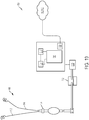
- a connector for connecting ureteral catheters configured to be positioned at a patient's ureter and/or kidney to a vacuum source for inducing negative pressure in the ureter and/or kidney and for connecting a bladder catheter to a fluid collection container for fluid collection of urine from the bladder by gravity drainage
- the connector comprising: a connector body; first and second ureteral catheter inflow ports extending from the connector body, the inflow ports each being configured to be connected to a ureteral catheter positioned in a patient's ureter and/or kidney; a ureteral catheter outflow port in fluid communication with each inflow port and being configured to be connected to a pump for inducing negative pressure in the respective ureteral catheters; a gravity drainage inflow port configured to be connected to a bladder catheter; and a gravity drainage outflow port in fluid communication with the bladder catheter inflow port and being configured to be connected to a fluid collection container.
- a urine collection assembly comprising: a first ureteral catheter configured to be positioned in a patient's ureter and/or kidney and a second ureteral catheter configured to be positioned in the patient's other ureter and/or kidney, the ureteral catheters each comprising: a drainage lumen portion defining a drainage lumen and comprising a proximal end, a distal end configured to be positioned in a patient's ureter and/or kidney, and a sidewall extending therebetween; and a retention portion extending radially outward from a portion of the distal end of the drainage lumen portion, and being configured to be extended into a deployed position in which a diameter of the retention portion is greater than a diameter of the drainage lumen portion, wherein at least one of the drainage lumen portion or the retention portion comprises at least one drainage port to permit fluid flow into the drainage lumen; and a bladder catheter for deployment within the patient's bladder, the bladder catheter comprising: a drainage lumen portion
- a bladder catheter for deployment within the patient's bladder for collecting excess urine not collected by deployed ureteral catheters positioned in the patient's ureter and/or kidney, the bladder catheter comprising: a drainage lumen portion defining a drainage lumen and comprising a proximal end portion, a distal end portion configured to be positioned in the patient's bladder, and a sidewall extending therebetween; and a deployable anchor portion configured to contact a proximal portion of the bladder wall to seal the urethral opening, wherein at least one of the drainage lumen portion or the anchor portion comprises at least one drainage port for permitting fluid flow into the drainage lumen for expelling urine from the bladder.
- a system for inducing negative pressure in a portion of a urinary tract of a patient, the system comprising: a ureteral catheter comprising: a drainage lumen portion comprising a proximal end, a distal end configured to be positioned in a patient's ureter and/or kidney, and a sidewall extending therebetween; and a retention portion extending radially outward from a portion of the distal end of the drainage lumen portion, and being configured to be extended into a deployed position in which a diameter of the retention portion is greater than a diameter of the drainage lumen portion, wherein at least one of the drainage lumen portion or the retention portion comprises at least one drainage port to permit fluid flow into the drainage lumen; and a pump in fluid communication with a drainage lumen defined by the drainage lumen portion of the ureteral catheter, the pump being configured for inducing a negative pressure in a portion of the urinary tract of the patient to draw fluid through the drainage lumen of the ureteral catheter.
- a method for extracting urine from a ureter and/or kidney of a patient for effecting interstitial pressure in the kidney comprising: positioning a distal end of a catheter at a fluid collection position within a patient's ureter and/or kidney, the catheter comprising a tube defining a drainage lumen and comprising a helical retention portion and a plurality of drainage ports; inducing a negative pressure within a drainage lumen of the catheter; and extracting urine by drawing urine through the drainage ports into the drainage lumen, thereby altering interstitial pressure within the patient's kidney.
- a method for inhibiting kidney damage by application of negative pressure to decrease interstitial pressure within tubules of the medullar region to facilitate urine output and to prevent venous congestion-induced nephron hypoxia in the medulla of the kidney comprising: deploying a ureteral catheter in the ureter and/or kidney of a patient such that flow of urine from the ureter and/or kidney is not prevented by occlusion of the ureter and/or kidney by the deployed catheter; and applying negative pressure to the ureter and/or kidney through the catheter for a predetermined period of time to facilitate urine output from the kidney.
- a method for treatment of acute kidney injury due to venous congestion comprising: deploying a ureteral catheter at a fluid collection position in the ureter and/or kidney of a patient such that the ureter and/or kidney is not occluded by the deployed catheter; and applying negative pressure to the ureter and/or kidney through the catheter for a predetermined period of time, thereby reducing venous congestion in the kidney to treat acute kidney injury.
- NYHA New York Heart Association
- proximal refers to the portion of the catheter device that is manipulated or contacted by a user and/or to a portion of an indwelling catheter nearest to the urinary tract access site.
- distal refers to the opposite end of the catheter device that is configured to be inserted into a patient and/or to the portion of the device that is inserted farthest into the patient's urinary tract.
- any numerical range recited herein is intended to include all sub-ranges subsumed therein.
- a range of "1 to 10" is intended to include any and all sub-ranges between and including the recited minimum value of 1 and the recited maximum value of 10, that is, all subranges beginning with a minimum value equal to or greater than 1 and ending with a maximum value equal to or less than 10, and all subranges in between, e.g., 1 to 6.3, or 5.5 to 10, or 2.7 to 6.1.
- the terms "communication” and "communicate” refer to the receipt or transfer of one or more signals, messages, commands, or other type of data.
- one unit or component to be in communication with another unit or component means that the one unit or component is able to directly or indirectly receive data from and/or transmit data to the other unit or component. This can refer to a direct or indirect connection that can be wired and/or wireless in nature.
- two units or components can be in communication with each other even though the data transmitted can be modified, processed, routed, and the like, between the first and second unit or component.
- a first unit can be in communication with a second unit even though the first unit passively receives data, and does not actively transmit data to the second unit.
- a first unit can be in communication with a second unit if an intermediary unit processes data from one unit and transmits processed data to the second unit. It will be appreciated that numerous other arrangements are possible.
- the present invention is generally directed to devices and methods for facilitating drainage of urine or waste from the bladder, ureter, and/or kidney(s) of a patient. In some examples, the present invention is generally directed to devices and methods for inducing a negative pressure in the bladder, ureter, and/or kidney(s) of a patient.
- Fluid retention and venous congestion are also central problems in the progression of prerenal Acute Kidney Injury (AKI).
- AKI can be related to loss of perfusion or blood flow through the kidney(s).
- the present invention facilitates improved renal hemodynamics and increases urine output for the purpose of relieving or reducing venous congestion.
- treatment and/or inhibition of AKI positively impacts and/or reduces the occurrence of other conditions, for example, reduction or inhibition of worsening renal function in patients with NYHA Class III and/or Class IV heart failure.
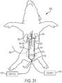
- the urinary tract comprises a patient's right kidney 2 and left kidney 4.
- the kidneys 2, 4 are responsible for blood filtration and clearance of waste compounds from the body through urine.
- Urine produced by the right kidney 2 and the left kidney 4 is drained into a patient's bladder 10 through tubules, namely a right ureter 6 and a left ureter 8.
- urine may be conducted through the ureters 6, 8 by peristalsis of the ureter walls, as well as by gravity.
- the ureters 6, 8 enter the bladder 10 through a ureter orifice or opening 16.
- the bladder 10 is a flexible and substantially hollow structure adapted to collect urine until the urine is excreted from the body.
- the bladder 10 is transitionable from an empty position (signified by reference line E) to a full position (signified by reference line F). Normally, when the bladder 10 reaches a substantially full state, urine is permitted to drain from the bladder 10 to a urethra 12 through a urethral sphincter or opening 18 located at a lower portion of the bladder 10. Contraction of the bladder 10 can be responsive to stresses and pressure exerted on a trigone region 14 of the bladder 10, which is the triangular region extending between the ureteral openings 16 and the urethral opening 18.
- the trigone region 14 is sensitive to stress and pressure, such that as the bladder 10 begins to fill, pressure on the trigone region 14 increases. When a threshold pressure on the trigone region 14 is exceeded, the bladder 10 begins to contract to expel collected urine through the urethra 12.
- a urine collection assembly 100 including ureteral catheters 112, 114 configured to be positioned within the urinary tract of a patient is illustrated.
- distal ends 120, 121 of the ureteral catheters 112, 114 can be configured to be deployed in the patient's ureters 2, 4 and, in particular, in a renal pelvis 20, 21 area of the kidneys 6, 8.
- the urine collection assembly 100 can comprise two separate ureteral catheters, such as a first catheter 112 disposed in or adjacent to the renal pelvis 20 of the right kidney 2 and a second catheter 114 disposed in or adjacent to the renal pelvis 21 of the left kidney 4.
- the catheters 112, 114 can be separate for their entire lengths, or can be held in proximity to one another by a clip, ring, clamp, or other type of connection mechanism (e.g., connector 150) to facilitate placement or removal of the catheters 112, 114.
- catheters 112, 114 can merge or be connected together to form a single drainage lumen.
- the catheters 112, 114 can be inserted through or enclosed within another catheter, tube, or sheath along portions or segments thereof to facilitate insertion and retraction of the catheters 112, 114 from the body.
- a bladder catheter 116 can be inserted over and/or along the same guidewire as the ureteral catheters 112, 114, thereby causing the ureteral catheters 112, 114 to extend from the distal end of the bladder catheter 116.
- an exemplary ureteral catheter 112 can comprise at least one elongated body or tube 122, the interior of which defines or comprises one or more drainage channel(s) or lumen(s), such as drainage lumen 124.
- the tube 122 size can range from about 1 Fr to about 9 Fr (French catheter scale).
- the tube 122 can have an external diameter ranging from about 0.33 to about 3 mm, and an internal diameter ranging from about 0.165 to about 2.39 mm.
- the tube 122 is 6 Fr and has an outer diameter of 2.0 ⁇ 0.1 mm.
- the length of the tube 122 can range from about 30 cm to about 120 cm depending on the age (e.g., pediatric or adult) and gender of the patient.
- the tube 122 can be formed from a flexible and/or deformable material to facilitate advancing and/or positioning the tube 122 in the bladder 10 and ureters 6, 8 (shown in FIG. 1 ).
- the catheter material should be flexible and soft enough to avoid or reduce irritation of the renal pelvis and ureter, but should be rigid enough that the tube 122 does not collapse when the renal pelvis or other portions of the urinary tract exert pressure on the exterior of the tube 122, or when the renal pelvis and/or ureter are drawn against the tube 122 during inducement of negative pressure.
- the tube 122 can be formed from materials including biocompatible polymers, polyvinyl chloride, polytetrafluoroethylene (PTFE) such as Teflon®, silicon coated latex, or silicon.
- PTFE polytetrafluoroethylene
- the tube 122 is formed from a thermoplastic polyurethane. At least a portion or all of the catheter 112, such as the tube 122, can be coated with a hydrophilic coating to facilitate insertion and/or removal, and/or to enhance comfort. In some examples, the coating is a hydrophobic and/or lubricious coating.
- suitable coatings can comprise ComfortCoat® hydrophilic coating which is available from Koninklijke DSM N.V. or hydrophilic coatings comprising polyelectrolyte(s) such as are disclosed in United States Patent No. 8,512,795 .
- the tube 122 can comprise: a distal portion 118 (e.g., a portion of the tube 122 configured to be positioned in the ureter 6, 8 and renal pelvis 20, 21); a middle portion 126 (e.g., a portion of the tube 122 configured to extend from the distal portion through the ureteral openings 16 into the patient's bladder 10 and urethra 12); and a proximal portion 128 (e.g., a portion of the tube 122 extending from the urethra 12 to an external fluid collection container and/or pump assembly).
- the combined length of the proximal portion 128 and the middle portion 126 of the tube 122 is about 54 ⁇ 2 cm.
- the tube 122 terminates in another indwelling catheter and/or drainage lumen, such as in a drainage lumen of the bladder catheter 116. In that case, fluid drains from the proximal end of the ureteral catheter 112, 114 and is directed from the body through the additional indwelling catheter and/or drainage lumen.
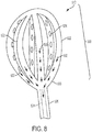
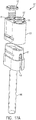
- the distal portion 118 of the ureteral catheter 112 comprises a retention portion 130 for maintaining the distal end 120 of the catheter 112 at a desired fluid collection position proximate to or within the renal pelvis 20, 21 of the kidney 2, 4.
- the retention portion 130 is configured to be flexible and bendable to permit positioning of the retention portion 130 in the ureter and/or renal pelvis.
- the retention portion 130 is desirably sufficiently bendable to absorb forces exerted on the catheter 112 and to prevent such forces from being translated to the ureters. For example, if the retention portion 130 is pulled in the proximal direction P (shown in FIG.
- the retention portion 130 can be sufficiently flexible to begin to unwind or be straightened so that it can be drawn through the ureter. Similarly, when the retention portion 130 can be reinserted into the renal pelvis or other suitable region within the ureter, it can be biased to return to its deployed configuration.
- the retention portion 130 is integral with the tube 122.
- the retention portion 130 can be formed by imparting a bend or curl to the catheter body 122 that is sized and shaped to retain the catheter at a desired fluid collection location.
- Suitable bends or coils can include a pigtail coil, corkscrew coil, and/or helical coil.
- the retention portion 130 can comprise one or more radially and longitudinally extending helical coils configured to contact and passively retain the catheter 112 within the ureter 6, 8 proximate to or within the renal pelvis 20, 21.
- the retention portion 130 is formed from a radially flared or tapered portion of the catheter body 122.
- the retention portion 130 can further comprise a fluid collecting portion, as shown in FIGS. 4A and 4B , such as a tapered or funnel-shaped inner surface 186.
- the retention portion 130 can comprise a separate element connected to and extending from the catheter body or tube 122.
- the retention portion 130 can further comprise one or more perforated sections, such as drainage holes or ports 132 (shown in FIGS. 3A-3E ).
- a drainage port can be located, for example, at the open distal end 120, 121 of the tube 122.
- perforated sections and/or drainage ports 132 are disposed along the sidewall of the distal portion 118 of the catheter tube 122.
- the drainage ports or holes can be used for assisting in fluid collection.
- the retention portion 130 is solely a retention structure and fluid collection and/or imparting negative pressure is provided by structures at other locations on the catheter tube 122.
- exemplary retention portions 130 comprising a plurality of helical coils, such as one or more full coils 184 and one or more half or partial coils 183, are illustrated.
- the retention portion 130 is capable of moving between a contracted position and the deployed position with the plurality of helical coils.
- a substantially straight guidewire can be inserted through the retention portion 130 to maintain the retention portion 130 in a substantially straight contracted position.
- the retention portion 130 can transition to its coiled configuration.
- the coils 183, 184 extend radially and longitudinally from the distal portion 118 of the tube 122.
- the retention portion 130 comprises two full coils 184 and one half coil 183.
- the outer diameter of the full coils 184, shown by line D1 can be about 18 ⁇ 2 mm.
- the half coil 183 diameter D2 can be about 14 mm.
- the coiled retention portion 130 has a height H of about 16 ⁇ 2 mm.
- the retention portion 130 can further comprise the one or more drainage holes 132 (shown in FIGS. 3A-3E ) configured to draw fluid into an interior of the catheter tube 122.
- the retention portion 130 can comprise six drainage holes, plus an additional hole at the distal tip 120 of the retention portion. The diameter of each of the drainage holes 132 (shown in FIGS.
- 3A-3E can range from about 0.7 mm to 0.9 mm and, preferably, is about 0.83 ⁇ 0.01 mm.
- the distance between adjacent drainage holes 132 specifically the linear distance between drainage holes 132 when the coils are straightened, can be about 22.5 ⁇ 2.5 mm.
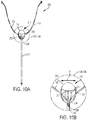
- the distal portion 118 of the drainage lumen proximal to the retention portion 130 defines a straight or curvilinear central axis L.
- at least a half or first coil 183 and a full or second coil 184 of the retention portion 130 extend about an axis A of the retention portion 130.
- the first coil 183 initiates or begins at a point where the tube 122 is bent at an angle ⁇ ranging from about 15 degrees to about 75 degrees from the central axis L, as indicated by angle ⁇ , and preferably about 45 degrees.
- angle ⁇ ranging from about 15 degrees to about 75 degrees from the central axis L, as indicated by angle ⁇ , and preferably about 45 degrees.
- the axis A prior to insertion in the body, can be coextensive with the longitudinal central axis L. In other examples, as shown in FIGS. 3C-3E , prior to insertion in the body, the axis A extends from and is curved or angled, for example at angle ⁇ , relative to the central longitudinal axis L.
- multiple coils 184 can have the same inner and/or outer diameter D and height H2.
- the outer diameter D1 of the coils 184 may range between 10 mm and 30 mm.
- the height H2 between coils 184 may be about 3 mm to 10 mm.
- the retention portion 130 is configured to be inserted in the tapered portion of the renal pelvis.
- the outer diameter D1 of the coils 184 can increase toward the distal end 120 of the tube 122, resulting in a helical structure having a tapered or partially tapered configuration.
- the distal or maximum outer diameter D1 of the tapered helical portion ranges from about 10 mm to about 30 mm, which corresponds to the dimensions of the renal pelvis.
- the height H2 of the retention portion 130 ranges from about 10 mm to about 30 mm.
- the outer diameter D1 and/or height H2 of the coils 184 can vary in a regular or irregular fashion.
- the outer diameter D1 of coils or height H2 between coils can increase or decrease by a regular amount (e.g., about 10% to about 25% between adjacent coils 184).
- a regular amount e.g., about 10% to about 25% between adjacent coils 184.
- an outer diameter D3 of a proximal-most coil or first coil 183 can be about 6 mm to 18 mm
- an outer diameter D2 of a middle coil or second coil 185 can be about 8 mm to about 24 mm
- an outer diameter D1 of a distal-most or third coil 187 can be between about 10 mm and about 30 mm.
- the retention portion 130 can further comprise the drainage ports 132 or holes disposed on or through the sidewall of the catheter tube 122 on or adjacent to the retention portion 130 to permit urine waste to flow from the outside of the catheter tube 122 to the inside of the catheter tube 122.
- the position and size of the drainage ports 132 can vary depending upon the desired flow rate and configuration of the retention portion.
- the diameter of the drainage ports 132 can range from about 0.005 mm to about 1.0 mm.
- the spacing between the drainage ports 132 can range from about 1.5 mm to about 5 mm.
- the drainage ports 132 can be spaced in any arrangement, for example, linear or offset. In some examples, the drainage ports 132 can be non-circular, and can have a surface area of about .00002 to 0.79 mm 2 .
- the drainage ports 132 are located around the entire periphery of the sidewall of the catheter tube 122 to increase an amount of fluid that can be drawn into the drainage lumen 124 (shown in FIGS. 1 , 2A, and 2B ).
- the drainage ports 132 can be disposed essentially only or only on the radially inwardly facing side of the coils 184 to prevent occlusion or blockage of the drainage ports 132, and the outwardly facing side of the coils may be essentially free of drainage ports 132 or free of drainage ports 132.
- mucosal tissue of the ureter and/or kidney may be drawn against the retention portion 130 and may occlude some drainage ports 132 on the outer periphery of the retention portion 130. Drainage ports 132 located on the radially inward side of the retention structure would not be appreciably occluded when such tissues contact the outer periphery of the retention portion 130. Further, risk of injury to the tissues from pinching or contact with the drainage ports 132 can be reduced or ameliorated.
- the retention portion 130 comprises three coils 184 extending about the axis A.
- the axis A is a curved arc extending from the central longitudinal axis L of the portion of the drainage lumen 181 proximal to the retention portion 130.
- the curvature imparted to the retention portion 130 can be selected to correspond to the curvature of the renal pelvis, which comprises a cornucopia-shaped cavity.
- the retention portion 130 can comprise two coils 184 extending about an angled axis A.
- the angled axis A extends at an angle from a central longitudinal axis L, and is angled, as shown by angle ⁇ , relative to an axis generally perpendicular to the central axis L of the portion of the drainage lumen.
- the angle ⁇ can range from about 15 to about 75 degrees (e.g., about 105 to about 165 degrees relative to the central longitudinal axis L of the drainage lumen portion of the catheter 112).
- FIG. 3E shows another example of a ureteral catheter 112.
- the retention portion comprises three helical coils 184 extending about an axis A.
- the axis A is angled, as shown by angle ⁇ , relative to the horizontal.
- the angle ⁇ can range from about 15 to about 75 degrees (e.g., about 105 to about 165 degrees relative to the central longitudinal axis L of the drainage lumen portion of the catheter 112).
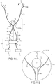
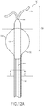
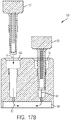
- a retention portion 130 of a ureteral catheter 112 comprises a catheter tube 122 having a widened and/or tapered distal end portion which, in some examples, is configured to be positioned in the patient's renal pelvis and/or kidney.
- the retention portion 130 can be a funnel-shaped structure comprising an outer surface 185 configured to be positioned against the ureter and/or kidney wall and comprising an inner surface 186 configured to direct fluid toward a drainage lumen 124 of the catheter 112.
- the retention portion 130 can comprise a proximal end 188 adjacent to the distal end of the drainage lumen 124 and having a first diameter D1 and a distal end 190 having a second diameter D2 that is greater than the first diameter D1 when the retention portion 130 is in its deployed position.
- the retention portion 130 is transitionable from a collapsed or compressed position to the deployed position.
- the retention portion 130 can be biased radially outward such that when the retention portion 130 is advanced to its fluid collecting position, the retention portion 130 (e.g., the funnel portion) expands radially outward to the deployed state.
- the retention portion 130 of the ureteral catheter 112 can be made from a variety of suitable materials that are capable of transitioning from the collapsed state to the deployed state.
- the retention portion 130 comprises a framework of tines or elongated members formed from a temperature sensitive shape memory material, such as nitinol.
- the nitinol frame can be covered with a suitable waterproof material such as silicon to form a tapered portion or funnel. In that case, fluid is permitted to flow down the inner surface 186 of the retention portion 130 and into the drainage lumen 124.
- the retention portion 130 is formed from various rigid or partially rigid sheets or materials bended or molded to form a funnel-shaped retention portion as illustrated in FIGS. 4A and 4B .
- the retention portion of the ureteral catheter 112 can include one or more mechanical stimulation devices 191 for providing stimulation to nerves and muscle fibers in adjacent tissues of the ureter(s) and renal pelvis.
- the mechanical stimulation devices 191 can include linear or annular actuators embedded in or mounted adjacent to portions of the sidewall of the catheter tube 122 and configured to emit low levels of vibration.
- mechanical stimulation can be provided to portions of the ureters and/or renal pelvis to supplement or modify therapeutic effects obtained by application of negative pressure. While not intending to be bound by theory, it is believed that such stimulation affects adjacent tissues by, for example, stimulating nerves and/or actuating peristaltic muscles associated with the ureter(s) and/or renal pelvis. Stimulation of nerves and activation of muscles may produce changes in pressure gradients or pressure levels in surrounding tissues and organs which may contribute to or, in some cases, enhance therapeutic benefits of negative pressure therapy.
- a retention portion 330 of a ureteral catheter 312 comprises a catheter tube 322 having a distal portion 318 formed in a helical structure 332 and an inflatable element or balloon 350 positioned proximal to the helical structure 332 to provide an additional degree of retention in the renal pelvis and/or fluid collection location.
- a balloon 350 can be inflated to pressure sufficient to retain the balloon in the renal pelvis or ureter, but low enough to avoid distending or damaging these structures. Suitable inflation pressures are known to those skilled in the art and are readily discernible by trial and error.
- the helical structure 332 can be imparted by bending the catheter tube 322 to form one or more coils 334.
- the coils 334 can have a constant or variable diameter and height as described above.
- the catheter tube 322 further comprises a plurality of drainage ports 336 disposed on the sidewall of the catheter tube 322 to allow urine to be drawn into the drainage lumen 324 of the catheter tube 322 and to be directed from the body through the drainage lumen 324, for example on the inwardly facing and/or outwardly facing sides of the coil 334.
- the inflatable element or balloon 350 can comprise an annular balloon-like structure having, for example, a generally heart-shaped cross section and comprising a surface or cover 352 defining a cavity 353.
- the cavity 353 is in fluid communication with an inflation lumen 354 extending parallel to the drainage lumen 324 defined by the catheter tube 322.
- the balloon 350 can be configured to be inserted in the tapered portion of the renal pelvis and inflated such that an outer surface 356 thereof contacts and rests against an inner surface of the ureter and/or renal pelvis.
- the inflatable element or balloon 350 can comprise a tapered inner surface 358 extending longitudinally and radially inward towards the catheter tube 322.
- the inner surface 358 can be configured to direct urine toward the catheter tube 322 to be drawn into the drainage lumen 324.
- the inner surface 358 can also be positioned to prevent fluid from pooling in the ureter, such as around the periphery of the inflatable element or balloon 350.
- the inflatable retention portion or balloon 350 is desirably sized to fit within the renal pelvis and can have a diameter ranging from about 10 mm to about 30 mm.
- an assembly 400 including a ureteral catheter 412 comprising a retention portion 410 is illustrated.
- the retention portion 410 is formed from a porous and/or sponge-like material that is attached to a distal end 421 of a catheter tube 422.
- the porous material can be configured to channel and/or absorb urine and direct the urine toward a drainage lumen 424 of the catheter tube 422.
- the retention portion 410 can be a porous wedge shaped-structure configured for insertion and retention in the patient's renal pelvis.
- the porous material comprises a plurality of holes and/or channels. Fluid can be drawn through the channels and holes, for example, by gravity or upon inducement of negative pressure through the catheter 412.
- fluid can enter the wedge-shaped retention portion 410 through the holes and/or channels and is drawn toward a distal opening 420 of the drainage lumen 424, for example, by capillary action, peristalsis, or as a result of the inducement of negative pressure in the holes and/or channels.
- the retention portion 410 comprises a hollow, funnel structure formed from the porous sponge-like material. As shown by arrow A, fluid is directed down an inner surface 426 of the funnel structure into the drainage lumen 424 defined by the catheter tube 422. Also, fluid can enter the funnel structure of the retention portion 410 through holes and channels in the porous sponge-like material of a sidewall 428.
- suitable porous materials can include open-celled polyurethane foams, such as polyurethane ether.
- Suitable porous materials can also include laminates of woven or non-woven layers comprising, for example, polyurethane, silicone, polyvinyl alcohol, cotton, or polyester, with or without antimicrobial additives such as silver, and with or without additives for modifying material properties such as hydrogels, hydrocolloids, acrylic, or silicone.
- a retention portion 500 of a ureteral catheter 512 comprises an expandable cage 530.
- the expandable cage 530 comprises one or more longitudinally and radially extending hollow tubes 522.
- the tubes 522 can be formed from an elastic, shape memory material such as nitinol.
- the cage 530 is configured to transition from a contracted state, for insertion through the patient's urinary tract, to a deployed state for positioning in the patient's ureters and/or kidney.
- the hollow tubes 522 comprise a plurality of drainage ports 534 which can be positioned on the tubes, for example, on radially inward facing sides thereof.
- the ports 534 are configured to permit fluid to flow or be drawn through the ports 534 and into the respective tubes 522.
- the fluid drains through the hollow tubes 522 into a drainage lumen 524 defined by a catheter body 526 of the ureteral catheter 512.
- fluid can flow along the path indicated by the arrows 532 in FIG. 8 .
- portions of the ureter wall and/or renal pelvis may be drawn against the outward facing surfaces of the hollow tubes 522.
- the drainage ports 534 are positioned and configured so as not to be appreciably occluded by ureteral structures upon application of negative pressure to the ureters and/or kidney.
- Exemplary urine collection assembly is
- the urine collection assembly 100 further comprises a bladder catheter 116.
- the distal ends 120, 121 of the ureteral catheters 112, 114 can be connected to the bladder catheter 116 to provide a single drainage lumen for urine, or the ureteral catheter(s) can drain via separate tube(s) from the bladder catheter 116.
- the bladder catheter 116 comprises a deployable seal and/or anchor 136 for anchoring, retaining, and/or providing passive fixation for indwelling portions of the urine collection assembly 100 and, in some examples, to prevent premature and/or untended removal of assembly components during use.
- the anchor 136 is configured to be located adjacent to the lower wall of the patient's bladder 10 (shown in FIG. 1 ) to prevent patient motion and/or forces applied to indwelling catheters 112, 114, 116 from translating to the ureters.
- the bladder catheter 116 comprises an interior of which defines a drainage lumen 140 configured to conduct urine from the bladder 10 to an external urine collection container 712 (shown in FIG. 19 ). In some examples, the bladder catheter 116 size can range from about 8 Fr to about 24 Fr.
- the bladder catheter 116 can have an external diameter ranging from about 2.7 to about 8 mm. In some examples, the bladder catheter 116 can have an internal diameter ranging from about 2.16 to about 6.2 mm.
- the bladder catheter 116 can be available in different lengths to accommodate anatomical differences for gender and/or patient size. For example, the average female urethra length is only a few inches, so the length of a tube 138 can be rather short. The average urethra length for males is longer due to the penis and can be variable. It is possible that woman can use bladder catheters 116 with longer length tubes 138 provided that the excess tubing does not increase difficulty in manipulating and/or preventing contamination of sterile portions of the catheter 116.
- a sterile and indwelling portion of the bladder catheter 116 can range from about 1 inch to 3 inches (for women) to about 20 inches for men.
- the total length of the bladder catheter 116 including sterile and non-sterile portions can be from one to several feet.
- the catheter tube 138 can comprise one or more drainage ports 142 configured to be positioned in the bladder 10 for drawing urine into the drainage lumen 140. For example, excess urine left in the patient's bladder 10 during placement of the ureteral catheters 112, 114 is expelled from the bladder 10 through the ports 142 and drainage lumen 140. In addition, any urine that is not collected by the ureteral catheters 112, 114 accumulates in the bladder 10, and can be conducted from the urinary tract through the drainage lumen 140.
- the drainage lumen 140 may be pressurized to a negative pressure to assist in fluid collection or may be maintained at atmospheric pressure such that fluid is collected by gravity and/or as a result of partial contraction of the bladder 10.
- the ureteral catheters 112, 114 may extend from the drainage lumen 140 of the bladder catheter 116 to facilitate and/or simplify insertion and placement of the ureteral catheters 112, 114.
- the deployable seal and/or anchor 136 is disposed at or adjacent to a distal end 148 of the bladder catheter 116.
- the deployable anchor 136 is configured to transition between a contracted state for insertion into the bladder 10 through the urethra 12 and urethral opening 18 and a deployed state.
- the anchor 136 is configured to be deployed in and seated adjacent to a lower portion of the bladder 10 and/or against the urethral opening 18.
- the anchor 136 can be positioned adjacent to the urethral opening 18 to enhance suction of a negative pressure applied to the bladder 10 or, in the absence of negative pressure, to partially, substantially, or entirely seal the bladder 10 to ensure that urine in the bladder 10 is directed through the drainage lumen 140 and to prevent leakage to the urethra 12.
- the anchor 136 can be about 12 Fr to 32 Fr (e.g., having a diameter of about 4 mm to about 10.7 mm) in the deployed state, and preferably between about 24 Fr and 30 Fr.
- a 24 Fr anchor has a diameter of about 8 mm.
- a 24 Fr anchor 136 would be a single size suitable for all or most patients.
- a suitable length of the anchor 136 is between about 1.0 cm and 2.3 cm, and preferably about 1.9 cm (about 0.75 in).
- an exemplary bladder anchor 136 in the form of an expandable balloon 144 is illustrated.
- the expandable (e.g., inflatable) balloon 144 can be, for example, a spherical balloon of a Foley catheter.
- the balloon 144 can be about 1.0 cm to 2.3 cm in diameter, and preferably about 1.9 cm (0.75 in) in diameter.
- the balloon 144 is preferably formed from a flexible material including, for example, biocompatible polymers, polyvinyl chloride, polytetrafluoroethylene (PTFE) such as Teflon®, silicon coated latex, or silicon.
- PTFE polytetrafluoroethylene
- the balloon 144 is in fluid connection with an inflation lumen 146, and is inflated by introducing fluid into the balloon 144.
- the balloon 144 can be a substantially spherical structure mounted to and extending radially outward from the catheter tube 138 of the bladder catheter 116 and comprising a central cavity or channel for the catheter tube 138 to pass through.
- the catheter tube 138 extends through the cavity defined by the balloon 144, such that the open distal end 148 of the catheter tube 138 extends distally beyond the balloon 144 and toward the center of the bladder 10 (shown in FIG. 1 ). Excess urine collected in the bladder 10 can be drawn into the drainage lumen 140 through the distal open end 148 thereof.
- the ureteral catheters 112, 114 extend from the open distal end 148 of the drainage lumen 140.
- the ureteral catheters 112, 114 extend through ports 172 or openings disposed on a sidewall of the catheter tube 138 at a position distal to the balloon 144.
- the ports 172 can be circular or oval shaped.
- the ports 172 are sized to receive the ureteral catheters 112, 114 and, accordingly, can have a diameter ranging from about 0.33 mm to about 3 mm. As shown in FIG.
- the bladder catheter 116 is positioned next to the balloon 144, rather than extending through a central cavity defined by the balloon 144.
- the ureteral catheters 112, 114 extend through ports 172 in the sidewall of the bladder catheter 116 and into the bladder 10.
- the bladder catheter 116 comprises a dual lumen catheter with the drainage lumen 140 at a central region thereof and a smaller inflation lumen 146 extending along the periphery of the catheter tube 138.
- the ureteral catheters 112, 114 are inserted or enclosed in the central drainage lumen 140.
- the ureteral catheters 112, 114 are single-lumen catheters having a sufficiently narrow cross section to fit within the drainage lumen 140. In some examples, as discussed above, the ureteral catheters 112, 114 extend through the entire bladder catheter 116.
- a bladder catheter 116a is a multi-lumen catheter that defines at least four lumens, namely a first lumen 112a for conducting fluid from the first ureteral catheter 112 (shown in FIG. 1 ), a second lumen 114a for conducting fluid from the second ureteral catheter 114 (shown in FIG. 1 ), a third lumen 140a for drainage of urine from the bladder 10 (shown in FIG. 1 ), and the inflation lumen 146a for conducting fluid to and from the balloon 144 (shown in FIG. 12A ) for inflation and retraction thereof.
- FIG. 15 another example of a catheter balloon 144 for use with a urine collection assembly 100 is illustrated.
- the balloon 144 is configured to be positioned partially within the patient's bladder 10 and partially within the urethra 12 to provide an enhanced bladder seal.
- a central portion 145 of the balloon 144 is configured to be radially contracted by the urethral opening 18, thereby defining a bulbous upper volume configured to be positioned in the lower portion of the bladder 10 and a bulbous lower volume configured to be position at the distal portion of the urethra 12.
- the bladder catheter 116 extends through a central cavity defined by the balloon 144 and toward a central portion of the bladder 10 and includes drainage ports 142 for conducting urine from the bladder 10 through a drainage lumen 140 of the catheter 116.
- the drainage ports 142 can be generally circular or oval shaped and can have a diameter of about 0.005 mm to about 0.5 mm.
- the bladder anchor device 134 comprises a bladder catheter 116 defining a drainage lumen 140, an inflation lumen 146, and an anchor 136, namely, another example of an expandable balloon 144, configured to be seated in a lower portion of the bladder 10.
- the ports 142 configured to receive the ureteral catheters 112, 114 are disposed proximal to and/or below the balloon 144.
- the ureteral catheters 112, 114 extend from the ports 142 and, as in previously-described examples, extend through the ureteral orifices or openings of the bladder and into the ureters.
- the ports 142 are disposed in a lower portion of the bladder adjacent to the urethral opening.
- the ureteral catheters 112, 114 extend from the ports 172 and between a lower portion of the balloon 144 and the bladder wall.
- the catheters 112, 114 may be positioned to prevent the balloon 144 and/or bladder wall from occluding the ports 142 so that excess urine collected in the bladder can be drawn into the ports 142 to be removed from the body.
- an expandable cage 210 anchors the assembly 200 in the bladder.
- the expandable cage 210 comprises a plurality of flexible members 212 or tines extending longitudinally and radially outward from a catheter body 238 of a bladder catheter 216 which, in some examples, can be similar to those discussed above with respect to the retention portion of the ureteral catheter of FIG. 8 .
- the members 212 can be formed from a suitable elastic and shape memory material such as nitinol. In a deployed position, the members 212 or tines are imparted with a sufficient curvature to define a spherical or ellipsoid central cavity 242.
- the cage 210 is attached to an open distal open end 248 of the catheter tube or body 238, to allow access to a drainage lumen 240 defined by the tube or body 238.
- the cage 210 is sized for positioning within the lower portion of the bladder and can define a diameter and length ranging from 1.0 cm to 2.3 cm, and preferably about 1.9 cm (0.75 in).
- the cage 210 further comprises a shield or cover 214 over distal portions of the cage 210 to prevent or reduce the likelihood that tissue, namely, the distal wall of the bladder, will be caught or pinched as a result of contact with the cage 210 or member 212. More specifically, as the bladder contracts, the inner distal wall of the bladder comes into contact with the distal side of the cage 210.
- the cover 214 prevents the tissue from being pinched or caught, may reduce patient discomfort, and protect the device during use.
- the cover 214 can be formed at least in part from a porous and/or permeable biocompatible material, such as a woven polymer mesh. In some examples, the cover 214 encloses all or substantially all of the cavity 242.
- the cover 214 defines openings suitable for receiving the ureteral catheters 112, 114. In some examples, the cover 214 covers only about the distal 2/3, about the distal half, or about the distal third portion or any amount, of the cage 210. In that case, the ureteral catheters 112, 114 pass through the uncovered portion of the cage 210.
- the cage 210 and cover 214 are transitionable from a contracted position, in which the members 212 are contracted tightly together around a central portion and/or around the bladder catheter 116 to permit insertion through a catheter or sheath to the deployed position.
- the cage 210 can be configured to transition to the deployed position when it is warmed to a sufficient temperature, such as body temperature (e.g., 37°C).
- body temperature e.g. 37°C
- the cage 210 has a diameter D that is preferably wider than the urethral opening, such that the cage 210 provides support for the ureteral catheters 112, 114 and prevents patient motion from translating through the ureteral catheters 112, 114 to the ureters.
- the ureteral catheter(s) 112, 114 extend from the open distal end 248 of the bladder catheter 216, past the longitudinally extending members 212 of the cage 210, and into the bladder.
- the open (e.g., low profile) arrangement of the members 212 or tines facilitates manipulation of the ureteral catheters 112, 114 from the bladder catheter 116 and through the bladder.
- the open arrangement of the members 212 or tines does not obstruct or occlude the distal opening 248 and/or drainage ports of the bladder catheter 216, making manipulation of the catheters 112, 114 easier to perform.
- the urine collection assembly 100b comprises a first ureteral catheter 112b and a second ureteral catheter 114b.
- the assembly 100b does not comprise a separate bladder drainage catheter as is provided in the previously-described examples.
- one of the ureteral catheters 112b comprises a helical portion 127b formed in the middle portion of the catheter 112b (e.g., the portion of the catheter configured to be positioned in a lower portion of the patient's bladder).
- the helical portion 127b comprises at least one and preferably two or more coils 176b.
- the coils 176b can be formed by bending a catheter tube 138b to impart a desired coil configuration.
- a lower coil 178b of the helical portion 127b is configured to be seated against and/or adjacent to the urethral opening.
- the helical portion 127b has a diameter D that is larger than the urethral opening to prevent the helical portion 127b from being drawn into the urethra.
- a port 142b or opening is disposed in the sidewall of the catheter tube 138b for connecting the first ureteral catheter 112b to the second ureteral catheter 114b.
- the second catheter 114b can be inserted in the port 142b to form a fluid connection between the first ureteral catheter 112b and the second ureteral catheter 114b.
- the second catheter 114b terminates at a position just inside a drainage lumen 140b of the first catheter 112b.
- the second ureteral catheter 114b is threaded through and/or extends along the length of the drainage lumen 140b of the first catheter 112b, but is not in fluid communication with the drainage lumen 140b.
- the assembly 100 includes ureteral catheters 112, 114 and a separate bladder catheter 116. More specifically, as in previously-described examples, the assembly 100 includes the ureteral catheters 112, 114, each of which comprise a distal portion 118 positioned in or adjacent to the right kidney and the left kidney, respectively.
- the ureteral catheters 112, 114 comprise indwelling portions 118, 126, 128 extending through the ureters, bladder, and urethra.
- the ureteral catheters 112, 114 further comprise an external portion 170 extending from the patient's urethra 12 to a pump assembly for imparting negative pressure to the renal pelvis and/or kidneys.
- the assembly 100 also includes a bladder anchor device 134 comprising a bladder catheter 116 and an anchor 136 (e.g., a Foley catheter) deployed in the bladder to prevent or reduce effects of patient motion from being translated to the ureteral catheters 112, 114 and/or ureters.
- the bladder catheter 116 extends from the bladder 10, through the urethra, and to a fluid collection container for fluid collection by gravity or negative pressure drainage.
- an external portion of the tubing extending between a collection vessel 712 and a pump 710 can comprise one or more filters for preventing urine and/or particulates from entering the pump.
- the bladder catheter 116 is provided to drain excess urine left in the patient's bladder during catheter placement.
- the assembly 100 further comprises a manifold or connector 150 for joining the two or more of the catheters 112, 114, 116 at a position outside the patient's body.
- the connector 150 can be a clamp, manifold, valve, fastener, or other element of a fluid path set, as is known in the art, for joining a catheter to external flexible tubing.
- the manifold or connector 150 comprises a two-piece body comprising an inner portion 151 mounted inside an outer housing 153.
- the inner portion 151 defines channels for conducting fluid between inflow ports 154, 155 and an outflow port 158.
- the inflow port(s) 154, 155 can comprise threaded sockets 157 configured to receive proximal portions of the catheters 112, 114.
- the sockets 157 are a suitable size to securely receive and hold flexible tubing sized between 1 Fr and 9 Fr.
- a user cinches the sockets 157 around the respective catheter tubes 122 by spinning the socket 157 into the ports 154, 155 in the direction of arrow A1 (shown in FIG. 17B ).
- the vacuum outflow port 158 can be connected to the fluid collection container 712 and/or pump assembly 710 (shown in FIG. 19 ) by, for example, flexible tubing 166 defining a fluid flow path.
- another exemplary connector 150 can be configured to connect three or more catheters 112, 114, 116 to outflow ports 158, 162.
- the connector 150 can comprise a structure or body having a distal side 152 comprising two or more vacuum inflow ports 154, 155 configured to be connected to proximal ends of the ureteral catheters 112, 114, and a separate gravity drainage port 156 configured to connect to the proximal end of the bladder catheter 116.
- the vacuum ports 154, 155 and/or proximal ends of the ureteral catheters 112, 114 can comprise a specific configuration to ensure that the ureteral catheters 112, 114 are connected to the vacuum source and not to some other fluid collection assembly.
- the gravity drainage port 156 and/or proximal end of the bladder catheter 116 can comprise another connector configuration to ensure that the bladder catheter 116 and not one of the ureteral catheters 112, 114 is permitted to drain by gravity drainage.
- the ports 154, 155, 156 and/or proximal ends of the catheters 112, 114, 116 can include visual indicia to assist in correctly setting up the fluid collection system.
- urine received in the vacuum ports 154, 155 can be directed through a Y-shaped conduit to a single vacuum outflow port 158 located on a proximal side 160 of the connector 150.
- the vacuum outflow port 158 can be connected to the fluid collection container 712 and/or pump 710 by suitable flexible tubing or other conduits for drawing urine from the body and for inducing negative pressure in the ureters and/or kidneys.
- the outflow port 156 and/or connector 150 can be configured to attach only to vacuum sources or pumps operating within a predetermined pressure range or power level to prevent exposing the ureteral catheters 112, 114 to elevated levels or intensity of negative pressure.
- the proximal side 160 of the connector 150 can also comprise a gravity outflow port 162 in fluid communication with the inflow port 156.
- the gravity outflow port 162 can be configured to be connected directly to the urine collection container 712 for urine collection by gravity drainage.
- the vacuum outflow port 158 and the gravity outflow port 162 are disposed in close proximity so that a single socket 164, bracket, or connector can be coupled to the connector 150 to establish fluid communication with each port 158, 162.
- the single socket or connector can be coupled to a multi-conduit hose or tube (e.g., flexible tubing 166) having a first conduit in fluid communication with the pump 710 and a second conduit in fluid communication with the collection container 712.
- a user can easily set up the external fluid collection system by inserting the single socket 164 in the connector 150 and connecting the respective conduits to one of the fluid collection container 712 and pump 710 (shown in FIG. 19 ).
- a length of flexible tubing 166 is connected between the urine collection container 712 and the gravity outflow port 162, and a separate length of flexible tubing is connected between the pump 710 and the vacuum outflow port 158.
- the assembly 100 further comprises sensors 174 for monitoring fluid characteristics of urine being collected from the ureters 6, 8 and/or bladder 10.
- information obtained from the sensors 174 can be transmitted to a central data collection module or processor and used, for example, to control operation of an external device, such as the pump 710 (shown in FIG. 19 ).
- the sensors 174 can be integrally formed with one or more of the catheters 112, 114, 116 such as, for example, embedded in a wall of the catheter body or tube and in fluid communication with drainage lumens 124, 140.
- one or more of the sensors 174 can be positioned in a fluid collection container 712 (shown in FIG. 19 ) or in internal circuitry of an external device, such as the pump 710.
- Exemplary sensors 174 that can be used with the urine collection assembly 100 can comprise one or more of the following sensor types.
- the catheter assembly 100 can comprise a conductance sensor or electrode that samples conductivity of urine.
- the normal conductance of human urine is about 5-10 mS/m. Urine having a conductance outside of the expected range can indicate that the patient is experiencing a physiological problem, which requires further treatment or analysis.
- the catheter assembly 100 can also comprise a flow meter for measuring a flow rate of urine through the catheter(s) 112, 114, 116. Flow rate can be used to determine a total volume of fluid excreted from the body.
- the catheter(s) 112, 114, 116 can also comprise a thermometer for measuring urine temperature. Urine temperature can be used to collaborate the conductance sensor. Urine temperature can also be used for monitoring purposes, as urine temperature outside of a physiologically normal range can be indicative of certain physiological conditions.
- the urine collection assembly 100 including the ureteral catheter retention portions and bladder anchor device (e.g., a standard or modified Foley-type catheter), methods for insertion and deployment of the assemblies will now be discussed in detail.
- bladder anchor device e.g., a standard or modified Foley-type catheter
- steps for positioning a fluid collection assembly in a patient's body and, optionally, for inducing negative pressure in a patient's ureter and/or kidneys are illustrated.
- a medical professional or caregiver inserts a flexible or rigid cystoscope through the patient's urethra and into the bladder to obtain visualization of the ureteral orifices or openings.
- a guidewire is advanced through the urethra, bladder, ureteral opening, ureter, and to a desired fluid collection position, such as the renal pelvis of the kidney.
- a ureteral catheter of the present invention (examples of which are discussed in detail above) is inserted over the guidewire to the fluid collection position, as shown at box 614.
- the location of the ureteral catheter can be confirmed by fluoroscopy, as shown at box 616.
- the retention portion of the ureteral catheter can be deployed.
- the guidewire can be removed from the catheter, thereby allowing the distal end and/or retention portion to transition to a deployed position.
- the deployed distal end portion of the catheter does not entirely occlude the ureter and/or renal pelvis, such that urine is permitted to pass outside the catheter and through the ureters into the bladder. Since moving the catheter can exert forces against urinary tract tissues, avoiding complete blockage of the ureters avoids application of force to the ureter sidewalls, which may cause injury.
- the same guidewire can be used to position a second ureteral catheter in the other ureter and/or kidney using the same insertion and positioning methods described herein.
- the cystoscope can be used to obtain visualization of the other ureteral opening in the bladder, and the guidewire can be advanced through the visualized ureteral opening to a fluid collection position in the other ureter.
- a catheter can be drawn alongside the guidewire and deployed in the manner described herein.
- the cystoscope and guidewire can be removed from the body. The cystoscope can be reinserted into the bladder over the first ureteral catheter.
- the cystoscope is used, in the manner described above, to obtain visualization of the ureteral opening and to assist in advancing a second guidewire to the second ureter and/or kidney for positioning of the second ureteral catheter.
- the guidewire and cystoscope are removed.
- the cystoscope and/or guidewire can remain in the bladder to assist with placement of the bladder catheter.
- a bladder catheter can also be used.
- the medical professional or caregiver can insert a distal end of a bladder catheter in a collapsed or contracted state through the urethra of the patient and into the bladder.
- the bladder catheter can be a conventional Foley bladder catheter or a bladder catheter of the present invention as discussed in detail above.
- an anchor connected to and/or associated with the bladder catheter is expanded to a deployed position. For example, when an expandable or inflatable catheter is used, fluid may be directed through an inflation lumen of the bladder catheter to expand a balloon structure located in the patient's bladder.
- the bladder catheter is inserted through the urethra and into the bladder without using a guidewire and/or cystoscope. In other examples, the bladder catheter is inserted over the same guidewire used to position the ureteral catheters. Accordingly, when inserted in this manner, the ureteral catheters can be arranged to extend from the distal end of the bladder catheter and, optionally, proximal ends of the ureteral catheters can be arranged to terminate in a drainage lumen of the bladder catheter.
- the urine is permitted to drain by gravity from the urethra.
- a negative pressure is induced in the ureteral catheter and/or bladder catheter to facilitate drainage of the urine.
- steps for using the urine collection assembly for inducement of negative pressure in the ureter(s) and/or kidney(s) are illustrated.
- the external proximal ends of the catheter(s) are connected to fluid collection or pump assemblies.
- the ureteral catheter(s) can be connected to a pump for inducing negative pressure at the patient's renal pelvis and/or kidney.
- the bladder catheter can be connected directly to a urine collection container for gravity drainage of urine from the bladder or connected to a pump for inducing negative pressure at the bladder.
- negative pressure is applied to the renal pelvis and/or kidney and/or bladder through the drainage lumens of the ureteral catheters and/or bladder catheter, as shown at box 626.
- the negative pressure is intended to counter congestion mediated interstitial hydrostatic pressures due to elevated intra-abdominal pressure and consequential or elevated renal venous pressure or renal lymphatic pressure.
- the applied negative pressure is therefore capable of increasing flow of filtrate through the medullary tubules and of decreasing water and sodium re-absorption.
- mechanical stimulation can be provided to portions of the ureters and/or renal pelvis to supplement or modify therapeutic affects obtained by application of negative pressure.
- mechanical stimulation devices such as linear actuators and other known devices for providing, for example, vibration waves, disposed in distal portions of the ureteral catheter(s) can be actuated. While not intending to be bound by theory, it is believed that such stimulation effects adjacent tissues by, for example, stimulating nerves and/or actuating peristaltic muscles associated with the ureter(s) and/or renal pelvis. Stimulation of nerves and activation of muscles may produce changes in pressure gradients or pressure levels in surrounding tissues and organs which may contribute to or, in some cases, enhance therapeutic benefits of negative pressure therapy.
- the mechanical stimulation can comprise pulsating stimulation.
- low levels of mechanical stimulation can be provided continuously as negative pressure is being provided through the ureteral catheter(s).
- inflatable portions of the ureteral catheter could be inflated and deflated in a pulsating manner to stimulate adjacent nerve and muscle tissue, in a similar manner to actuation of the mechanical stimulation devices described herein.
- urine is drawn into the catheter at the plurality of drainage ports at the distal end thereof, through the drainage lumen of the catheter, and to a fluid collection container for disposal.
- sensors disposed in the fluid collection system provide a number of measurements about the urine that can be used to assess the volume of urine collected, as well as information about the physical condition of the patient and composition of the urine produced.
- the information obtained by the sensors is processed, as shown at box 632, by a processor associated with the pump and/or with another patient monitoring device and, at box 634, is displayed to the user via a visual display of an associated feedback device.
- the system 700 can comprise the ureteral catheter(s), bladder catheter or the urine collection assembly 100 described hereinabove. As shown in FIG. 19 , ureteral catheters 112, 114 and/or the bladder catheter 116 of the assembly 100 are connected to one or more fluid collection containers 712 for collecting urine drawn from the renal pelvis and/or bladder. In some examples, the bladder catheter 116 and the ureteral catheters 112, 114 are connected to different fluid collection containers 712.
- the fluid collection container 712 connected to the ureteral catheter(s) 112, 114 can be in fluid communication with an external fluid pump 710 for generating negative pressure in the ureter(s) and kidney(s) through the ureteral catheter(s) 112, 114.
- negative pressure can be provided for overcoming interstitial pressure and forming urine in the kidney or nephron.
- a connection between the fluid collection container 712 and pump 710 can comprise a fluid lock or fluid barrier to prevent air from entering the renal pelvis or kidney in case of incidental therapeutic or non-therapeutic pressure changes.
- inflow and outflow ports of the fluid container can be positioned below a fluid level in the container.
- external portions of the tubing extending between the fluid collection container 712 and the pump 710 can include one or more filters to prevent urine and/or particulates from entering the pump 710.
- the system 700 further comprises a controller 714, such as a microprocessor, electronically coupled to the pump 710 and having or associated with computer readable memory 716.
- the memory 716 comprises instructions that, when executed, cause the controller 714 to receive information from sensors 174 located on or associated with portions of the assembly 100. Information about a condition of the patient can be determined based on information from the sensors 174. Information from the sensors 174 can also be used to determine and implement operating parameters for the pump 710.
- the controller 714 is incorporated in a separate and remote electronic device in communication with the pump 710, such as a dedicated electronic device, computer, tablet PC, or smart phone.
- the controller 714 can be included in the pump 710 and, for example, can control both a user interface for manually operating the pump 710, as well as system functions such as receiving and processing information from the sensors 174.
- the controller 714 is configured to receive information from the one or more sensors 174 and to store the information in the associated computer-readable memory 716.
- the controller 714 can be configured to receive information from the sensor 174 at a predetermined rate, such as once every second, and to determine a conductance based on the received information.
- the algorithm for calculating conductance can also include other sensor measurements, such as urine temperature, to obtain a more robust determination of conductance.
- the controller 714 can also be configured to calculate patient physical statistics or diagnostic indicators that illustrate changes in the patient's condition over time.
- the system 700 can be configured to identify an amount of total sodium excreted.
- the total sodium excreted may be based, for example, on a combination of flow rate and conductance over a period of time.
- the system 700 can further comprise a feedback device 720, such as a visual display or audio system, for providing information to the user.
- the feedback device 720 can be integrally formed with the pump 710.
- the feedback device 720 can be a separate dedicated or a multipurpose electronic device, such as a computer, laptop computer, tablet PC, smart phone, or other handheld electronic devices.
- the feedback device 720 is configured to receive the calculated or determined measurements from the controller 714 and to present the received information to a user via the feedback device 720.
- the feedback device 720 may be configured to display current negative pressure (in mmHg) being applied to the urinary tract.
- the feedback device 720 is configured to display current flow rate of urine, temperature, current conductance in mS/m of urine, total urine produced during the session, total sodium excreted during the session, other physical parameters, or any combination thereof.
- the feedback device 720 further comprises a user interface module or component that allows the user to control operation of the pump 710. For example, the user can engage or turn off the pump 710 via the user interface. The user can also adjust pressure applied by the pump 710 to achieve a greater magnitude or rate of sodium excretion and fluid removal.
- the feedback device 720 and/or pump 710 further comprise a data transmitter 722 for sending information from the device 720 and/or pump 710 to other electronic devices or computer networks.
- the data transmitter 722 can utilize a short-range or long-range data communications protocol.
- An example of a short-range data transmission protocol is Bluetooth®.
- Long-range data transmission networks include, for example, Wi-Fi or cellular networks.
- the data transmitter 722 can send information to a patient's physician or caregiver to inform the physician or caregiver about the patient's current condition. Alternatively, or in addition, information can be sent from the data transmitter 722 to existing databases or information storage locations, such as, for example, to include the recorded information in a patient's electronic health record (EHR).
- EHR electronic health record
- the pump 710 is a micro-pump configured to draw fluid from the catheter(s) 112, 114 (shown, for example, in FIG. 1 ) and having a sensitivity or accuracy of about 10 mmHg or less.
- the pump 710 is capable of providing a range of flow of urine between 0.05 ml/min and 3 ml/min for extended periods of time, for example, for about 8 hours to about 24 hours per day, for one (1) to about 30 days or longer. At 0.2 ml/min, it is anticipated that about 300 mL of urine per day is collected by the system 700.
- the pump 710 can be configured to provide a negative pressure to the bladder of the patient, the negative pressure ranging between about 0.1 mmHg and 50 mmHg or about 5 mmHg to about 20 mmHg (gauge pressure at the pump 710).
- a micro-pump manufactured by Langer Inc. Model BT100-2J
- Diaphragm aspirator pumps, as well as other types of commercially available pumps, can also be used for this purpose.
- Peristaltic pumps can also be used with the system 700.
- a piston pump, vacuum bottle, or manual vacuum source can be used for providing negative pressure.
- the system can be connected to a wall suction source, as is available in a hospital, through a vacuum regulator for reducing negative pressure to therapeutically appropriate levels.
- the pump 710 is configured for extended use and, thus, is capable of maintaining precise suction for extended periods of time, for example, for about 8 hours to about 24 hours per day, for 1 to about 30 days or longer. Further, in some examples, the pump 710 is configured to be manually operated and, in that case, includes a control panel 718 that allows a user to set a desired suction value.
- the pump 710 can also include a controller or processor, which can be the same controller that operates the system 700 or can be a separate processor dedicated for operation of the pump 710. In either case, the processor is configured for both receiving instructions for manual operation of the pump and for automatically operating the pump 710 according to predetermined operating parameters. Alternatively, or in addition, operation of the pump 710 can be controlled by the processor based on feedback received from the plurality of sensors associated with the catheter.
- the processor is configured to cause the pump 710 to operate intermittently.
- the pump 710 may be configured to emit pulses of negative pressure followed by periods in which no negative pressure is provided.
- the pump 710 can be configured to alternate between providing negative pressure and positive pressure to produce an alternating flush and pump effect.
- a positive pressure of about 0.1 mmHg to 20 mmHg, and preferably about 5 mmHg to 20 mmHg can be provided followed by a negative pressure ranging from about 0.1 mmHg to 50 mmHg.
- Example 1 Inducement of negative pressure within the renal pelvis of farm swine was performed for the purpose of evaluating effects of negative pressure therapy on renal congestion in the kidney. An objective of these studies was to demonstrate whether a negative pressure delivered into the renal pelvis significantly increases urine output in a swine model of renal congestion.
- Example 1 a pediatric Fogarty catheter, normally used in embolectomy or bronchoscopy applications, was used in the swine model solely for proof of principle for inducement of negative pressure in the renal pelvis. It is not suggested that a Fogarty catheter be used in humans in clinical settings to avoid injury of urinary tract tissues.
- Example 2 the ureteral catheter 112 shown in FIGS. 2A and 2B , and including a helical retention portion for mounting or maintaining a distal portion of the catheter in the renal pelvis or kidney, was used.
- FIG. 21 Four farm swine 800 were used for purposes of evaluating effects of negative pressure therapy on renal congestion in the kidney.
- pediatric Fogarty catheters 812, 814 were inserted to the renal pelvis region 820, 821 of each kidney 802, 804 of the four swine 800.
- the catheters 812, 814 were deployed within the renal pelvis region by inflating an expandable balloon to a size sufficient to seal the renal pelvis and to maintain the position of the balloon within the renal pelvis.
- the catheters 812, 814 extend from the renal pelvis 802, 804, through a bladder 810 and urethra 816, and to fluid collection containers external to the swine.
- Urine output of two animals was collected for a 15 minute period to establish a baseline for urine output volume and rate.
- Urine output of the right kidney 802 and the left kidney 804 were measured individually and found to vary considerably. Creatinine clearance values were also determined.
- Renal congestion (e.g., congestion or reduced blood flow in the veins of the kidney) was induced in the right kidney 802 and the left kidney 804 of the animal 800 by partially occluding the inferior vena cava (IVC) with an inflatable balloon catheter 850 just above to the renal vein outflow.
- IVC pressure Normal IVC pressures were 1-4 mmHg.
- the IVC pressures were elevated to between 15-25 mmHg.
- Inflation of the balloon to approximately three quarters of IVC diameter resulted in a 50-85% reduction in urine output.
- Full occlusion generated IVC pressures above 28 mmHg and was associated with at least a 95% reduction in urine output.
- One kidney of each animal 800 was not treated and served as a control ("the control kidney 802").
- the ureteral catheter 812 extending from the control kidney was connected to a fluid collection container 819 for determining fluid levels.
- One kidney (“the treated kidney 804") of each animal was treated with negative pressure from a negative pressure source (e.g., a therapy pump 818 in combination with a regulator designed to more accurately control the low magnitude of negative pressures) connected to the ureteral catheter 814.
- the pump 818 was an Air Cadet Vacuum Pump from Cole-Parmer Instrument Company (Model No. EW-07530-85).
- the pump 818 was connected in series to the regulator.
- the regulator was an V-800 Series Miniature Precision Vacuum Regulator - 1/8 NPT Ports (Model No. V-800-10-W/K), manufactured by Airtrol Components Inc.
- the pump 818 was actuated to induce negative pressure within the renal pelvis 820, 821 of the treated kidney according to the following protocol.
- Four different pressure levels (-2, -10, -15, and -20 mmHg) were applied for 15 minutes each and the rate of urine produced and creatinine clearance were determined. Pressure levels were controlled and determined at the regulator.
- the IVC balloon was inflated to increase the pressure by 15-20 mmHg.
- the same four negative pressure levels were applied.
- Urine output rate and creatinine clearance rate for the congested control kidney 802 and treated kidney 804 were obtained.
- the animals 800 were subject to congestion by partial occlusion of the IVC for 90 minutes. Treatment was provided for 60 minutes of the 90 minute congestion period.
- kidneys from one animal were subjected to gross examination then fixed in a 10% neutral buffered formalin. Following gross examination, histological sections were obtained, examined, and magnified images of the sections were captured. The sections were examined using an upright Olympus BX41 light microscope and images were captured using an Olympus DP25 digital camera. Specifically, photomicrograph images of the sampled tissues were obtained at low magnification (20x original magnification) and high magnification (100x original magnification). The obtained images were subjected to histological evaluation. The purpose of the evaluation was to examine the tissue histologically and to qualitatively characterize congestion and tubular degeneration for the obtained samples.
- Urine output rates were highly variable. Three sources of variation in urine output rate were observed during the study. The inter-individual and hemodynamic variability were anticipated sources of variability known in the art. A third source of variation in urine output, upon information and belief believed to be previously unknown, was identified in the experiments discussed herein, namely, contralateral intra-individual variability in urine output.
- Baseline urine output rates were 0.79 ml/min for one kidney and 1.07 ml/min for the other kidney (e.g., a 26% difference).
- the urine output rate is a mean rate calculated from urine output rates for each animal.
- Creatinine clearance measurements for baseline, congested, and treated portions for one of the animals are shown in FIG. 22 .
- control kidney right kidney
- treated kidney left kidney
- Qualitative evaluation of the magnified section images also noted increased congestion in the control kidney compared to the treated kidney.
- the treated kidney exhibited lower levels of congestion and tubular degeneration compared to the control kidney.
- the following qualitative scale was used for evaluation of the obtained slides.
- FIGS. 23A and 23B are low and high magnification photomicrographs of the left kidney (treated with negative pressure) of the animal. Based on the histological review, mild congestion in the blood vessels at the corticomedullary junction was identified, as indicated by the arrows. As shown in FIG. 23B , a single tubule with a hyaline cast (as identified by the asterisk) was identified.
- FIGS. 23C and 23D are low and high resolution photomicrographs of the control kidney (right kidney). Based on the histological review, moderate congestion in the blood vessel at the corticomedullary junction was identified, as shown by the arrows in FIG. 23C . As shown in FIG. 23D , several tubules with hyaline casts were present in the tissue sample (as identified by asterisks in the image). Presence of a substantial number of hyaline casts is evidence of hypoxia.
- the treated kidney was determined to have 1.5 times greater fluid volume in Bowman's space and 2 times greater fluid volume in tubule lumen. Increased fluid volume in Bowman's space and the tubule lumen corresponds to increased urine output. In addition, the treated kidney was determined to have 5 times less blood volume in capillaries compared to the control kidney. The increased volume in the treated kidney appears to be a result of (1) a decrease in individual capillary size compared to the control and (2) an increase in the number of capillaries without visible red blood cells in the treated kidney compared to the control kidney, an indicator of less congestion in the treated organ.
- hypoxemia of the organ follows. Hypoxemia interferes with oxidative phosphorylation within the organ (e.g., ATP production). Loss of ATP and/or a decrease in ATP production inhibits the active transport of proteins causing intraluminal protein content to increase, which manifests as hyaline casts.
- the number of renal tubules with intraluminal hyaline casts correlates with the degree of loss of renal function. Accordingly, the reduced number of tubules in the treated left kidney is believed to be physiologically significant. While not intending to be bound by theory, it is believed that these results show that damage to the kidney can be prevented or inhibited by applying negative pressure to a catheter inserted into the renal pelvis to facilitate urine output.
- the retention portion included two full coils and one proximal half coil.
- the outer diameter of the full coils shown by line D1 in FIGS. 2A and 2B , was 18 ⁇ 2 mm.
- the half coil diameter D2 was about 14 mm.
- the retention portion of the deployed ureteral catheters included six drainage holes, plus an additional hole at the distal end of the catheter tube. The diameter of each of the drainage holes was 0.83 ⁇ 0.01 mm.
- the distance between adjacent drainage holes 132 specifically the linear distance between drainage holes when the coils were straightened, was 22.5 ⁇ 2.5 mm.
- the ureteral catheters were positioned to extend from the renal pelvis of the swine, through the bladder, and urethra, and to fluid collection containers external to each swine. Following placement of the ureteral catheters, pressure sensors for measuring IVC pressure were placed in the IVC at a position distal to the renal veins.
- An inflatable balloon catheter specifically a PTS® percutaneous balloon catheter (30 mm diameter by 5 cm length), manufactured by NuMED Inc. of Hopkinton, NY, was expanded in the IVC at a position proximal to the renal veins.
- a thermodilution catheter specifically a Swan-Ganz thermodilution pulmonary artery catheter manufactured by Edwards Lifesciences Corp. of Irvine, CA, was then placed in the pulmonary artery for the purpose of measuring cardiac output.
- baseline urine output was measured for 30 minutes, and blood and urine samples were collected for biochemical analysis.
- the balloon catheter was inflated to increase IVC pressure from a baseline pressure of 1-4 mmHg to an elevated congested pressure of about 20 mmHg (+/- 5 mmHg).
- a congestion baseline was then collected for 30 minutes with corresponding blood and urine analysis.
- the elevated congested IVC pressure was maintained and negative pressure diuresis treatment was provided for swine A and swine C.
- the swine (A, C) were treated by applying a negative pressure of -25 mmHg through the ureteral catheters with a pump.
- the pump was an Air Cadet Vacuum Pump from Cole-Parmer Instrument Company (Model No. EW-07530-85).
- the pump was connected in series to a regulator.
- the regulator was a V-800 Series Miniature Precision Vacuum Regulator - 1/8 NPT Ports (Model No. V-800-10-W/K), manufactured by Airtrol Components Inc.
- the swine were observed for 120 minutes, as treatment was provided. Blood and urine collection were performed every 30 minutes, during the treatment period. Two of the swine (B, D) were treated as congested controls (e.g., negative pressure was not applied to the renal pelvis through the ureteral catheters), meaning that the two swine (B, D) did not receive negative pressure diuresis therapy.
- Animal A The animal weighed 50.6 kg and had a baseline urine output rate of 3.01 ml/min, a baseline serum creatinine of 0.8 mg/dl, and a measured CrCl of 261 ml/min. It is noted that these measurements, aside from serum creatinine, were uncharacteristically high relative to other animals studied. Congestion was associated with a 98% reduction in urine output rate (0.06 ml/min) and a >99% reduction in CrCl (1.0 ml/min). Treatment with negative pressure applied through the ureteral catheters was associated with urine output and CrCl of 17% and 12%, respectively, of baseline values, and 9x and >10x, respectively, of congestion values.
- Levels of NGAL changed throughout the experiment, ranging from 68% of baseline during congestion to 258% of baseline after 90 minutes of therapy. The final value was 130% of baseline.
- Levels of KIM-1 were 6 times and 4 times of baseline for the first two 30-minute windows after baseline assessment, before increasing to 68x, 52x, and 63x of baseline values, respectively, for the last three collection periods.
- the 2-hour serum creatinine was 1.3 mg/dl. Histological examination revealed an overall congestion level, measured by blood volume in capillary space, of 2.4%. Histological examination also noted several tubules with intraluminal hyaline casts and some degree of tubular epithelial degeneration, a finding consistent with cellular damage.
- Animal B The animal weighed 50.2 kg and had a baseline urine output rate of 2.62 ml/min and a measured CrCl of 172 ml/min (also higher than anticipated). Congestion was associated with an 80% reduction in urine output rate (0.5 ml/min) and an 83% reduction in CrCl (30 ml/min). At 50 minutes into the congestion (20 minutes after the congestion baseline period), the animal experienced an abrupt drop in mean arterial pressure and respiration rate, followed by tachycardia. The anesthesiologist administered a dose of phenylephrine (75 mg) to avert cardiogenic shock. Phenylephrine is indicated for intravenous administration when blood pressure drops below safe levels during anesthesia. However, since the experiment was testing the impact of congestion on renal physiology, administration of phenylephrine confounded the remainder of the experiment.
- Animal C The animal weighed 39.8 kg and had a baseline urine output rate of 0.47 ml/min, a baseline serum creatinine of 3.2 mg/dl, and a measured CrCl of 5.4 ml/min. Congestion was associated with a 75% reduction in urine output (0.12 ml/min) and a 79% reduction in CrCl (1.6 ml/min). It was determined that baseline NGAL levels were >5x the upper limit of normal (ULN). Treatment with negative pressure applied to the renal pelvis through the ureteral catheters was associated with a normalization of urine output (101% of baseline) and a 341% improvement in CrCl (18.2 ml/min).
- Levels of NGAL changed throughout the experiment, ranging from 84% of baseline during congestion to 47% to 84% of baseline between 30 and 90 minutes. The final value was 115% of baseline.
- Levels of KIM-1 decreased 40% from baseline within the first 30 minutes of congestion, before increasing to 8.7x, 6.7x, 6.6x, and 8x of baseline values, respectively, for the remaining 30-minute windows.
- Serum creatinine level at 2 hours was 3.1 mg/dl. Histological examination revealed an overall congestion level, measured by blood volume in capillary space, of 0.9%. The tubules were noted to be histologically normal.
- Animal D The animal weighed 38.2 kg and had a baseline urine output of 0.98 ml/min, a baseline serum creatinine of 1.0 mg/dl, and a measured CrCl of 46.8 ml/min. Congestion was associated with a 75% reduction in urine output rate (0.24 ml/min) and a 65% reduction in Cr Cl (16.2 ml/min). Continued congestion was associated with a 66% to 91% reduction of urine output and 89% to 71% reduction in CrCl. Levels of NGAL changed throughout the experiment, ranging from 127% of baseline during congestion to a final value of 209% of baseline.
- Levels of KIM-1 remained between 1x and 2x of baseline for the first two 30-minute windows after baseline assessment, before increasing to 190x, 219x, and 201x of baseline values for the last three 30-minute periods.
- the 2-hour serum creatinine level was 1.7 mg/dl.
- Histological examination revealed an overall congestion level 2.44x greater than that observed in tissue samples for the treated animals (A, C) with an average capillary size 2.33 times greater than that observed in either of the treated animals.
- the histological evaluation also noted several tubules with intraluminal hyaline casts as well as tubular epithelial degeneration, indicating substantial cellular damage.
- the data also appears to support the hypothesis that venous congestion decreases the filtration gradients in the medullary nephrons by altering the interstitial pressures.
- the change appears to directly contribute to the hypoxia and cellular injury within medullary nephrons. While this model does not mimic the clinical condition of AKI, it does provide insight into the mechanical sustaining injury.
Landscapes
- Health & Medical Sciences (AREA)
- Heart & Thoracic Surgery (AREA)
- Life Sciences & Earth Sciences (AREA)
- General Health & Medical Sciences (AREA)
- Public Health (AREA)
- Engineering & Computer Science (AREA)
- Anesthesiology (AREA)
- Biomedical Technology (AREA)
- Hematology (AREA)
- Animal Behavior & Ethology (AREA)
- Veterinary Medicine (AREA)
- Pulmonology (AREA)
- Biophysics (AREA)
- Vascular Medicine (AREA)
- Urology & Nephrology (AREA)
- Child & Adolescent Psychology (AREA)
- Ophthalmology & Optometry (AREA)
- Otolaryngology (AREA)
- Surgery (AREA)
- Epidemiology (AREA)
- External Artificial Organs (AREA)
- Prostheses (AREA)
- Media Introduction/Drainage Providing Device (AREA)
- Pharmaceuticals Containing Other Organic And Inorganic Compounds (AREA)
Claims (15)
- Sonde urétérale (112), comprenant :
une lumière de drainage comprenant une partie proximale et une partie distale conçues pour être positionnées dans l'uretère et/ou le rein d'un patient, la partie distale comprenant une partie de retenue spiralée (130) comprenant un tube (122), la partie de retenue spiralée (130) comprenant:au moins un premier enroulement (184) possédant un premier diamètre;au moins un deuxième enroulement (184) possédant un second diamètre, le premier diamètre étant inférieur au second diamètre; le deuxième enroulement (184) étant plus près d'une extrémité distale (120) de la partie distale (118) de la lumière de drainage que le premier enroulement (183) etune ou plusieurs perforations (132) sur une paroi latérale du tube (122) pour permettre un écoulement de fluide dans la lumière de drainage,dans laquelle la paroi latérale comprend un côté tourné radialement vers l'intérieur et un côté tourné radialement vers l'extérieur, et dans laquelle une surface totale pour des perforations (132) sur le côté tourné radialement vers l'intérieur est supérieure à une surface totale de perforations (132) sur le côté tourné radialement vers l'extérieur. - Sonde urétérale selon la revendication 1, dans laquelle le diamètre externe des enroulements augmente vers l'extrémité distale du tube, ce qui donne une structure hélicoïdale ayant une configuration conique ou partiellement conique.
- Sonde urétérale (112) selon la revendication 1, dans laquelle, avant l'introduction dans le conduit urinaire du patient, une partie de la lumière de drainage qui est proche de la partie de retenue (130) définit un axe central rectiligne ou curviligne, et dans laquelle le premier enroulement (184) et le deuxième enroulement (184) de la partie de retenue s'étendent autour d'un axe qui est au moins partiellement coextensif à l'axe central rectiligne ou curviligne de la partie de la lumière de drainage.
- Sonde urétérale (112) selon la revendication 3, dans laquelle l'axe de la partie de retenue (130) est courbé par rapport à l'axe central de la lumière de drainage.
- Sonde urétérale (112) selon l'une quelconque des revendications 1 à 4, la sonde pouvant passer d'une configuration contractée pour une introduction dans l'uretère du patient à une configuration déployée pour un déploiement à l'intérieur de l'uretère et/ou du rein.
- Sonde urétérale (112) selon l'une quelconque des revendications 3 à 5, dans laquelle la partie de retenue (130) comprend en outre un troisième enroulement (184) s'étendant autour de l'axe de la partie de retenue, le troisième enroulement (184) possédant un diamètre supérieur ou égal soit au premier diamètre, soit au second diamètre.
- Sonde urétérale (112) selon l'une quelconque des revendications 1 à 6, dans laquelle la partie proximale de la lumière de drainage est conçue pour être positionnée dans au moins une partie de l'urètre du patient.
- Sonde urétérale (112) selon l'une quelconque des revendications 1 à 7, dans laquelle le côté tourné radialement vers l'extérieur du tube est essentiellement dépourvu de perforations (132), de préférence dépourvu de perforations (132).
- Sonde urétérale (112) selon l'une quelconque des revendications 1 à 8, dans laquelle la ou chacune des perforations (132) a un diamètre d'environ 0,7 à environ 0,9 mm.
- Sonde urétérale (112) selon l'une quelconque des revendications 1 à 9, dans laquelle la partie de retenue (130) de la lumière de drainage comprend en outre une extrémité distale ouverte pour permettre un écoulement de fluide dans la lumière de drainage.
- Sonde urétérale (112) selon l'une quelconque des revendications 1 à 10, dans laquelle le premier diamètre du premier enroulement (184) est d'environ 8 mm à 10 mm et le second diamètre du deuxième enroulement (184) est d'environ 16 mm à 20 mm.
- Sonde urétérale (112) selon l'une quelconque des revendications 1 à 11, dans laquelle le premier enroulement (184) comprend une paroi latérale comprenant un côté tourné radialement vers l'intérieur et un côté tourné radialement vers l'extérieur, le côté tourné radialement vers l'intérieur du premier enroulement (184) comprenant une ou plusieurs perforations (132) pour permettre un écoulement de fluide dans la lumière de drainage.
- Sonde urétérale (112) selon l'une quelconque des revendications 1 à 12, dans laquelle le premier enroulement (184) comprend une paroi latérale comprenant un côté tourné radialement vers l'intérieur et un côté tourné radialement vers l'extérieur, le côté tourné radialement vers l'intérieur du premier enroulement comprenant au moins deux perforations (132) pour permettre un écoulement de fluide dans la lumière de drainage.
- Sonde urétérale (112) selon l'une quelconque des revendications 1 à 13, dans laquelle le premier enroulement (184) comprend une paroi latérale comprenant un côté tourné radialement vers l'intérieur et un côté tourné radialement vers l'extérieur, le côté tourné radialement vers l'extérieur du premier enroulement étant essentiellement dépourvu de ou dépourvu d'une ou de plusieurs perforations (132).
- Sonde urétérale (112) selon l'une quelconque des revendications 1 à 13, dans laquelle le premier enroulement (184) comprend une paroi latérale comprenant un côté tourné radialement vers l'intérieur et un côté tourné radialement vers l'extérieur, le côté tourné radialement vers l'intérieur du premier enroulement (184) comprenant une ou plusieurs perforations (132) pour permettre un écoulement de fluide dans la lumière de drainage et le côté tourné radialement vers l'extérieur étant essentiellement dépourvu de ou dépourvu d'une ou de plusieurs perforations (132).
Priority Applications (5)
| Application Number | Priority Date | Filing Date | Title |
|---|---|---|---|
| EP21177624.0A EP3922295A1 (fr) | 2015-07-20 | 2016-07-20 | Cathéters urétéraux et vésicaux pour induire une pression négative afin d'augmenter la perfusion rénale |
| EP21170520.7A EP3912669A1 (fr) | 2015-07-20 | 2016-07-20 | Cathéters urétéraux et vésicaux et procédés pour induire une pression négative afin d'augmenter la perfusion rénale |
| EP19176565.0A EP3636311B1 (fr) | 2015-07-20 | 2016-07-20 | Cathéters urétéraux et vésicaux pour induire une pression négative afin d'augmenter la perfusion rénale |
| EP18179384.5A EP3479867A3 (fr) | 2015-07-20 | 2016-07-20 | Cathéters urétéraux et vésicaux et procédés pour induire une pression négative afin d'augmenter la perfusion rénale |
| PL16828458T PL3325078T3 (pl) | 2015-07-20 | 2016-07-20 | Cewnik moczowodowy i cewnik do pęcherza moczowego |
Applications Claiming Priority (5)
| Application Number | Priority Date | Filing Date | Title |
|---|---|---|---|
| US201562194585P | 2015-07-20 | 2015-07-20 | |
| US201562260966P | 2015-11-30 | 2015-11-30 | |
| US201662278721P | 2016-01-14 | 2016-01-14 | |
| US201662300025P | 2016-02-25 | 2016-02-25 | |
| PCT/US2016/043110 WO2017015351A2 (fr) | 2015-07-20 | 2016-07-20 | Sondes urétérales et vésicales, et procédés d'induction d'une pression négative pour augmenter la perfusion rénale |
Related Child Applications (6)
| Application Number | Title | Priority Date | Filing Date |
|---|---|---|---|
| EP21177624.0A Division EP3922295A1 (fr) | 2015-07-20 | 2016-07-20 | Cathéters urétéraux et vésicaux pour induire une pression négative afin d'augmenter la perfusion rénale |
| EP21170520.7A Division EP3912669A1 (fr) | 2015-07-20 | 2016-07-20 | Cathéters urétéraux et vésicaux et procédés pour induire une pression négative afin d'augmenter la perfusion rénale |
| EP18179384.5A Division-Into EP3479867A3 (fr) | 2015-07-20 | 2016-07-20 | Cathéters urétéraux et vésicaux et procédés pour induire une pression négative afin d'augmenter la perfusion rénale |
| EP18179384.5A Division EP3479867A3 (fr) | 2015-07-20 | 2016-07-20 | Cathéters urétéraux et vésicaux et procédés pour induire une pression négative afin d'augmenter la perfusion rénale |
| EP19176565.0A Division EP3636311B1 (fr) | 2015-07-20 | 2016-07-20 | Cathéters urétéraux et vésicaux pour induire une pression négative afin d'augmenter la perfusion rénale |
| EP19176565.0A Division-Into EP3636311B1 (fr) | 2015-07-20 | 2016-07-20 | Cathéters urétéraux et vésicaux pour induire une pression négative afin d'augmenter la perfusion rénale |
Publications (3)
| Publication Number | Publication Date |
|---|---|
| EP3325078A2 EP3325078A2 (fr) | 2018-05-30 |
| EP3325078A4 EP3325078A4 (fr) | 2018-08-08 |
| EP3325078B1 true EP3325078B1 (fr) | 2020-02-12 |
Family
ID=57834600
Family Applications (5)
| Application Number | Title | Priority Date | Filing Date |
|---|---|---|---|
| EP21170520.7A Pending EP3912669A1 (fr) | 2015-07-20 | 2016-07-20 | Cathéters urétéraux et vésicaux et procédés pour induire une pression négative afin d'augmenter la perfusion rénale |
| EP16828458.6A Active EP3325078B1 (fr) | 2015-07-20 | 2016-07-20 | Sondes urétérales et vésicales |
| EP19176565.0A Active EP3636311B1 (fr) | 2015-07-20 | 2016-07-20 | Cathéters urétéraux et vésicaux pour induire une pression négative afin d'augmenter la perfusion rénale |
| EP21177624.0A Pending EP3922295A1 (fr) | 2015-07-20 | 2016-07-20 | Cathéters urétéraux et vésicaux pour induire une pression négative afin d'augmenter la perfusion rénale |
| EP18179384.5A Pending EP3479867A3 (fr) | 2015-07-20 | 2016-07-20 | Cathéters urétéraux et vésicaux et procédés pour induire une pression négative afin d'augmenter la perfusion rénale |
Family Applications Before (1)
| Application Number | Title | Priority Date | Filing Date |
|---|---|---|---|
| EP21170520.7A Pending EP3912669A1 (fr) | 2015-07-20 | 2016-07-20 | Cathéters urétéraux et vésicaux et procédés pour induire une pression négative afin d'augmenter la perfusion rénale |
Family Applications After (3)
| Application Number | Title | Priority Date | Filing Date |
|---|---|---|---|
| EP19176565.0A Active EP3636311B1 (fr) | 2015-07-20 | 2016-07-20 | Cathéters urétéraux et vésicaux pour induire une pression négative afin d'augmenter la perfusion rénale |
| EP21177624.0A Pending EP3922295A1 (fr) | 2015-07-20 | 2016-07-20 | Cathéters urétéraux et vésicaux pour induire une pression négative afin d'augmenter la perfusion rénale |
| EP18179384.5A Pending EP3479867A3 (fr) | 2015-07-20 | 2016-07-20 | Cathéters urétéraux et vésicaux et procédés pour induire une pression négative afin d'augmenter la perfusion rénale |
Country Status (18)
| Country | Link |
|---|---|
| US (10) | US9744331B2 (fr) |
| EP (5) | EP3912669A1 (fr) |
| JP (7) | JP6450886B2 (fr) |
| CN (3) | CN113350654B (fr) |
| AU (5) | AU2016296866B2 (fr) |
| BR (2) | BR122021007973B1 (fr) |
| CA (4) | CA3152431A1 (fr) |
| CL (2) | CL2018000153A1 (fr) |
| CO (1) | CO2018000580A2 (fr) |
| DK (1) | DK3325078T3 (fr) |
| ES (1) | ES2784704T3 (fr) |
| HK (1) | HK1248612A1 (fr) |
| HU (1) | HUE049050T2 (fr) |
| MA (2) | MA42500A (fr) |
| MX (1) | MX2018000823A (fr) |
| PL (1) | PL3325078T3 (fr) |
| RU (2) | RU2720403C2 (fr) |
| WO (1) | WO2017015351A2 (fr) |
Families Citing this family (62)
| Publication number | Priority date | Publication date | Assignee | Title |
|---|---|---|---|---|
| NZ718101A (en) | 2008-05-01 | 2017-07-28 | Convatec Technologies Inc | Rectal drain appliance |
| JP6224460B2 (ja) | 2011-03-17 | 2017-11-01 | コンバテック・テクノロジーズ・インコーポレイテッドConvatec Technologies Inc | 高バリアエラストマーの糞便カテーテルまたはオストミーパウチ |
| CN114288545A (zh) | 2013-08-01 | 2022-04-08 | 康沃特克科技公司 | 自闭合的袋连接器 |
| CA2949755C (fr) | 2014-06-15 | 2022-08-02 | Paragate Medical Ltd. | Dialyse peritoneale implantable continue |
| US11510765B2 (en) | 2015-01-23 | 2022-11-29 | Spinal Singularity, Inc. | Extended-use catheters |
| US9775698B2 (en) | 2015-01-23 | 2017-10-03 | Spinal Singularity, Inc. | Urinary prosthesis systems |
| US11065093B2 (en) | 2015-01-23 | 2021-07-20 | Spinal Singularity, Inc. | Catheter mating devices |
| US11040172B2 (en) | 2015-07-20 | 2021-06-22 | Strataca Systems Limited | Ureteral and bladder catheters and methods of inducing negative pressure to increase renal perfusion |
| US10765834B2 (en) | 2015-07-20 | 2020-09-08 | Strataca Systems Limited | Ureteral and bladder catheters and methods of inducing negative pressure to increase renal perfusion |
| US10493232B2 (en) | 2015-07-20 | 2019-12-03 | Strataca Systems Limited | Ureteral catheters, bladder catheters, systems, kits and methods for inducing negative pressure to increase renal function |
| US10512713B2 (en) | 2015-07-20 | 2019-12-24 | Strataca Systems Limited | Method of removing excess fluid from a patient with hemodilution |
| US11541205B2 (en) | 2015-07-20 | 2023-01-03 | Roivios Limited | Coated urinary catheter or ureteral stent and method |
| RU2720403C2 (ru) | 2015-07-20 | 2020-04-29 | Стратака Системз Лимитед, Мт | Мочеточниковый катетер и мочепузырный катетер и способы создания отрицательного давления для увеличения почечной перфузии |
| US11040180B2 (en) | 2015-07-20 | 2021-06-22 | Strataca Systems Limited | Systems, kits and methods for inducing negative pressure to increase renal function |
| US10926062B2 (en) | 2015-07-20 | 2021-02-23 | Strataca Systems Limited | Ureteral and bladder catheters and methods of inducing negative pressure to increase renal perfusion |
| US10918827B2 (en) | 2015-07-20 | 2021-02-16 | Strataca Systems Limited | Catheter device and method for inducing negative pressure in a patient's bladder |
| US11229771B2 (en) | 2015-07-20 | 2022-01-25 | Roivios Limited | Percutaneous ureteral catheter |
| WO2018045301A1 (fr) * | 2016-09-02 | 2018-03-08 | Regents Of The University Of California | Endoprothèse urétérale et procédés associés |
| US11439797B2 (en) * | 2017-02-10 | 2022-09-13 | Medtronic Advanced Energy Llc. | Surgical drain system and container |
| WO2018148646A1 (fr) * | 2017-02-13 | 2018-08-16 | University Of Pittsburgh - Of The Commonwealth System Of Higher Education | Canule percutanée extensible |
| WO2018200052A1 (fr) * | 2017-04-25 | 2018-11-01 | Strataca Systems Limited | Sondes urétérales et vésicales et procédés d'induction d'une pression négative pour accroître la perfusion rénale |
| EP3634516A1 (fr) | 2017-05-14 | 2020-04-15 | Paragate Medical Ltd. | Système implantable d'extraction de fluide |
| CN107174677A (zh) * | 2017-06-28 | 2017-09-19 | 九铭瑞华(北京)生物医学科技有限公司 | 一种导尿装置 |
| CN109200347A (zh) * | 2017-06-29 | 2019-01-15 | 上海氪励铵勤科技发展有限公司 | 引流装置 |
| US9987464B1 (en) | 2017-07-20 | 2018-06-05 | Donaco Medical Design, LLC | Urinary catheter insertion device and kit |
| US10881842B2 (en) * | 2017-07-28 | 2021-01-05 | Gyrus Acmi, Inc. | Ureteral stent |
| CN111278479B (zh) * | 2017-08-25 | 2023-11-21 | 罗维奥斯有限公司 | 输尿管和膀胱导管以及引入负压以增加肾灌注的方法 |
| CN111263653B (zh) * | 2017-08-25 | 2022-06-03 | 罗维奥斯有限公司 | 促进从尿道除尿的排尿泵 |
| AU2018342615A1 (en) * | 2017-09-29 | 2020-04-09 | Spinal Singularity, Inc. | Indwelling catheter, catheter introducer mating device and system comprising both |
| US10933227B2 (en) * | 2017-12-01 | 2021-03-02 | Gyrus Acmi, Inc. | Ureteral stent |
| GB201721955D0 (en) | 2017-12-27 | 2018-02-07 | Convatec Ltd | Catheter wetting devices |
| GB201721956D0 (en) | 2017-12-27 | 2018-02-07 | Convatec Ltd | Female catheter locator tip |
| CA3098570C (fr) | 2018-05-01 | 2023-09-26 | Purewick Corporation | Dispositifs de collecte de fluide, systemes associes et procedes associes |
| CN109172896A (zh) * | 2018-10-26 | 2019-01-11 | 大连科万维医疗科技有限公司 | 一种防堵塞心房引流管 |
| US10983032B2 (en) | 2018-11-13 | 2021-04-20 | International Business Machines Corporation | Automatic control of the separation and collection of fluid |
| US10704994B2 (en) | 2018-11-13 | 2020-07-07 | International Business Machines Corporation | Apparatus for automatic separation and collection of fluid |
| TW202034864A (zh) | 2018-11-30 | 2020-10-01 | 馬爾他商史翠塔卡系統有限公司 | 經皮導尿管 |
| TW202034863A (zh) | 2018-11-30 | 2020-10-01 | 馬爾他商史翠塔卡系統有限公司 | 用於誘發負壓以增加腎功能的輸尿管導管、膀胱導管、系統、套件、及方法 |
| CN113382756A (zh) * | 2018-11-30 | 2021-09-10 | 斯特拉塔卡系统有限公司 | 涂覆和/或浸渍输尿管导管或支架及其制造方法 |
| EP3920771A4 (fr) * | 2019-02-07 | 2022-11-02 | Solace Therapeutics, Inc. | Dispositif d'atténuation de pression |
| CN109953776B (zh) * | 2019-04-09 | 2023-11-17 | 江南大学 | 肾盂尿液微生态采集仪 |
| CA3138967A1 (fr) * | 2019-04-23 | 2020-10-29 | Roivios Limited | Ensemble pompe et systeme pour induire une pression negative dans une partie des voies urinaires d'un patient |
| US11628271B2 (en) | 2019-06-10 | 2023-04-18 | Spinal Singularity, Inc. | Urinary catheter |
| AU2020290905A1 (en) | 2019-06-11 | 2021-11-18 | Convatec Technologies Inc. | Urine collection bags for use with catheter products, kits incorporating the same, and methods therefor |
| US11083830B2 (en) * | 2019-10-14 | 2021-08-10 | Fresenius Medical Care Holdings, Inc. | Implantable fluid conduit |
| CN110743090A (zh) * | 2019-12-05 | 2020-02-04 | 南京市儿童医院 | 一种医用输尿管支架及其使用方法 |
| US20210177355A1 (en) * | 2019-12-11 | 2021-06-17 | Biosense Webster (Israel) Ltd. | Balloon Catheter with Position Sensors |
| WO2021126698A1 (fr) * | 2019-12-18 | 2021-06-24 | Potrero Medical, Inc. | Systèmes, dispositifs et procédés de drainage et d'analyse de fluides corporels et d'évaluation de la santé |
| US11717642B2 (en) | 2020-04-24 | 2023-08-08 | Covidien Lp | Catheter including one or more sensors |
| US20210370019A1 (en) | 2020-05-28 | 2021-12-02 | Strataca Systems Limited | Method of Treatment Using Negative Pressure Renal Therapy and Medicament(s) |
| GB2611491A (en) * | 2020-06-24 | 2023-04-05 | Winston Weisse Charles | Ureteral bypass devices and procedures |
| US11744498B2 (en) | 2020-07-17 | 2023-09-05 | Covidien Lp | Catheter system |
| CN112401833B (zh) * | 2020-10-12 | 2022-12-06 | 温州医科大学附属第二医院、温州医科大学附属育英儿童医院 | 带测压肾盂导管 |
| CN112295087B (zh) * | 2020-10-29 | 2023-06-06 | 合肥达米医疗科技有限公司 | 连续缓释给药镇痛引流管 |
| CN112295088B (zh) * | 2020-10-29 | 2023-06-06 | 合肥达米医疗科技有限公司 | 具有控制器的连续缓释给药镇痛引流管 |
| US20220142843A1 (en) * | 2020-11-11 | 2022-05-12 | Purewick Corporation | Urine collection system including a flow meter and related methods |
| IL308762A (en) * | 2021-05-25 | 2024-01-01 | Asic Medical Buha Ltd | System and method for self-catheterization and voiding of urine |
| CN113633250A (zh) * | 2021-06-22 | 2021-11-12 | 桐乡市第一人民医院 | 一种术中肠镜肠壁固定装置 |
| US20230060814A1 (en) | 2021-08-13 | 2023-03-02 | 3Ive Labs, Llc | Negative Pressure Therapy System and Methods |
| US20230068431A1 (en) | 2021-08-13 | 2023-03-02 | 3Ive Labs, Llc | Negative Pressure Therapy System and Methods |
| WO2024059244A1 (fr) | 2022-09-15 | 2024-03-21 | 3Ive Labs, Llc | Dispositifs, systèmes et méthodes de traitement par pression négative avec des cathéters urinaires à demeure |
| CN116942988A (zh) * | 2023-09-21 | 2023-10-27 | 中国人民解放军总医院第三医学中心 | 一种泌尿科用排尿装置 |
Family Cites Families (455)
| Publication number | Priority date | Publication date | Assignee | Title |
|---|---|---|---|---|
| US1870942A (en) | 1928-05-26 | 1932-08-09 | Gynex Corp | Syringe |
| US2285980A (en) | 1939-07-25 | 1942-06-09 | American Cystoscope Makers Inc | Ureteral catheter |
| US2649092A (en) | 1949-10-26 | 1953-08-18 | American Cystoscope Makers Inc | Catheter |
| US3108595A (en) | 1960-08-08 | 1963-10-29 | Alfred P Overment | Retention catheter |
| US3397699A (en) | 1966-05-05 | 1968-08-20 | Gerald C. Kohl | Retaining catheter having resiliently biased wing flanges |
| US3561431A (en) | 1968-06-10 | 1971-02-09 | Sorenson Research Corp | Central venous pressure monitor system and manometer scale therefor |
| US3707967A (en) | 1970-10-01 | 1973-01-02 | Tecna Corp | Steady flow regenerative peritoneal dialysis system and method |
| US3875941A (en) | 1974-04-03 | 1975-04-08 | Medical Dynamics Inc | System for evacuating fluids from the body |
| US3938529A (en) | 1974-07-22 | 1976-02-17 | Gibbons Robert P | Indwelling ureteral catheter |
| US3943929A (en) * | 1974-11-15 | 1976-03-16 | The Kendall Company | Multi-chamber container and method |
| US3938530A (en) | 1974-11-15 | 1976-02-17 | Santomieri Louis | Catheter |
| FR2366023A1 (fr) | 1976-07-30 | 1978-04-28 | Inst Nat Sante Rech Med | Procede et appareil de reglage des conditions d'hemodialyse |
| US4306557A (en) | 1978-08-29 | 1981-12-22 | North Daniel A | Vacuum urological surgical irrigating solution collecting system |
| US4265243A (en) * | 1979-04-04 | 1981-05-05 | The Kendall Company | Collection container with siphon assembly |
| US4349029A (en) * | 1980-06-16 | 1982-09-14 | Mott Patricia A | Drainage balloon catheter system |
| US4437856A (en) | 1981-02-09 | 1984-03-20 | Alberto Valli | Peritoneal catheter device for dialysis |
| US4425124A (en) * | 1981-04-06 | 1984-01-10 | Womack Charles E | Catheter assembly |
| SE433445B (sv) | 1981-04-16 | 1984-05-28 | Erik Gustav Percy Nordqvist | Urinkateter |
| US4531933A (en) * | 1982-12-07 | 1985-07-30 | C. R. Bard, Inc. | Helical ureteral stent |
| US4568338A (en) * | 1983-09-22 | 1986-02-04 | C. R. Bard, Inc. | Preformed catheter |
| US4710169A (en) | 1983-12-16 | 1987-12-01 | Christopher T Graham | Urinary catheter with collapsible urethral tube |
| US4571241A (en) | 1983-12-16 | 1986-02-18 | Christopher T Graham | Urinary catheter with collapsible urethral tube |
| US4671795A (en) | 1984-11-19 | 1987-06-09 | Mulchin William L | Permanent/retrievable ureteral catheter |
| US4629015A (en) | 1984-11-28 | 1986-12-16 | Cobe Asdt, Inc. | Weight monitoring system |
| US4681564A (en) * | 1985-10-21 | 1987-07-21 | Landreneau Michael D | Catheter assembly having balloon extended flow path |
| US4738667A (en) | 1986-11-04 | 1988-04-19 | Galloway Niall T M | Preformed catheter assembly |
| US4834724A (en) * | 1987-04-06 | 1989-05-30 | Geiss Alan C | Device for aspirating fluids from a body cavity or hollow organ |
| DE8705894U1 (fr) | 1987-04-23 | 1987-06-19 | Fresenius Ag, 6380 Bad Homburg, De | |
| US4813935A (en) | 1987-07-27 | 1989-03-21 | Habley Medical Technology Corporation | Urinary catheter |
| JPS6480367A (en) * | 1987-09-21 | 1989-03-27 | Terumo Corp | Member for correcting ureter |
| US4957479A (en) | 1988-10-17 | 1990-09-18 | Vance Products Incorporated | Indwelling ureteral stent placement apparatus |
| US5011488A (en) | 1988-12-07 | 1991-04-30 | Robert Ginsburg | Thrombus extraction system |
| US4935004A (en) | 1988-12-20 | 1990-06-19 | Henry Ford Health System | Peritoneal dialysis catheter |
| US5116309A (en) * | 1989-01-25 | 1992-05-26 | Coll Milton E | Ureteral stent-catheter system having varying diameter stent |
| FR2644212B1 (fr) | 1989-03-13 | 1991-11-15 | Malbec Edouard | Cassette pour pompe peristaltique a tube deformable, et pompe peristaltique equipee d'une telle cassette |
| US4945895A (en) | 1989-03-20 | 1990-08-07 | Vance Products Incorporated | Remote fiber optic medical procedure and device |
| US4932938A (en) | 1989-05-05 | 1990-06-12 | Medical Engineering Corporation | Urethral indwelling catheter with incontinence control |
| US5059169A (en) | 1989-07-07 | 1991-10-22 | C. R. Bard, Inc. | High-friction prostatic stent |
| US4950228A (en) * | 1990-01-10 | 1990-08-21 | Knapp Jr Peter M | Ureteral stent |
| US5041093A (en) | 1990-01-31 | 1991-08-20 | Boston Scientific Corp. | Catheter with foraminous anchor |
| JPH042361A (ja) * | 1990-04-19 | 1992-01-07 | Olympus Optical Co Ltd | 溶解治療装置用カテーテル |
| US5193533A (en) * | 1990-07-09 | 1993-03-16 | Brigham And Women's Hospital | High-pressure jet ventilation catheter |
| US5098440A (en) | 1990-08-14 | 1992-03-24 | Cordis Corporation | Object retrieval method and apparatus |
| US6461346B1 (en) | 1990-08-29 | 2002-10-08 | Applied Medical Resources Corp. | Sealing occlusion catheter and method of using same |
| US5451215A (en) | 1990-09-17 | 1995-09-19 | Wolter; Dietmar | Suction drain for the aspiration of discharges |
| DE4104702C2 (de) | 1991-02-15 | 1996-01-18 | Malte Neuss | Implantate für Organwege in Wendelform |
| US5141502A (en) * | 1991-08-28 | 1992-08-25 | Macaluso Jr Joseph N | Ureteral stent |
| US5662713A (en) | 1991-10-09 | 1997-09-02 | Boston Scientific Corporation | Medical stents for body lumens exhibiting peristaltic motion |
| US5256146A (en) | 1991-10-11 | 1993-10-26 | W. D. Ensminger | Vascular catheterization system with catheter anchoring feature |
| US6471872B2 (en) | 1991-10-11 | 2002-10-29 | Children's Hospital Medical Center | Hemofiltration system and method based on monitored patient parameters |
| US5370690A (en) | 1992-02-28 | 1994-12-06 | Mayo Foundation For Medical Education And Research | Artificial bladder |
| US5769821A (en) | 1992-03-02 | 1998-06-23 | Quinton Instrument Company | Catheter tip retainer |
| US5514112A (en) | 1992-10-02 | 1996-05-07 | Boston Scientific Corporation | Drainage catheter and method of use |
| US5599291A (en) | 1993-01-04 | 1997-02-04 | Menlo Care, Inc. | Softening expanding ureteral stent |
| RU2113245C1 (ru) * | 1993-01-18 | 1998-06-20 | Магомед-Салах Алхазурович Газимиев | Устройство для длительного пассажа мочи |
| US5523092A (en) * | 1993-04-14 | 1996-06-04 | Emory University | Device for local drug delivery and methods for using the same |
| US5401257A (en) | 1993-04-27 | 1995-03-28 | Boston Scientific Corporation | Ureteral stents, drainage tubes and the like |
| US5451218A (en) | 1993-09-15 | 1995-09-19 | Moore; Patrick S. | Urinary drainage device |
| US5505717A (en) | 1993-09-15 | 1996-04-09 | Moore; Patrick S. | Urinary drainage device |
| CN2175619Y (zh) | 1993-10-16 | 1994-08-31 | 吴志坚 | 变径尿道支架引流管 |
| US5554145A (en) | 1994-02-28 | 1996-09-10 | The Procter & Gamble Company | Absorbent article with multiple zone structural elastic-like film web extensible waist feature |
| US5762599A (en) | 1994-05-02 | 1998-06-09 | Influence Medical Technologies, Ltd. | Magnetically-coupled implantable medical devices |
| US5540701A (en) * | 1994-05-20 | 1996-07-30 | Hugh Sharkey | Passive fixation anastomosis method and device |
| US5554114A (en) * | 1994-10-20 | 1996-09-10 | Micro Therapeutics, Inc. | Infusion device with preformed shape |
| US5562622A (en) | 1995-03-20 | 1996-10-08 | Contimed, Inc. | Self-cleansing bladder drainage device |
| US6364868B1 (en) | 1995-08-02 | 2002-04-02 | The Trustees Of Columbia University In The City Of New York | Ureteral catheter and tissue expander and method of megaureter creation |
| NL1001564C2 (nl) | 1995-11-02 | 1997-05-13 | Timotheus Theodorus Cornelis O | Systeem van apparaten voor het behandelen van de ureter en/of de pyelo-ureterovergang. |
| US6676623B2 (en) | 2001-05-04 | 2004-01-13 | Scimed Life Systems, Inc. | Drainage devices and methods |
| US5895398A (en) | 1996-02-02 | 1999-04-20 | The Regents Of The University Of California | Method of using a clot capture coil |
| US6402736B1 (en) * | 1996-02-16 | 2002-06-11 | Joe E. Brown | Apparatus and method for filtering intravascular fluids and for delivering diagnostic and therapeutic agents |
| US5785641A (en) * | 1996-05-08 | 1998-07-28 | Urocath Corporation | Male indwelling urethral catheter sizing system and insertion method |
| US5647843A (en) | 1996-05-24 | 1997-07-15 | Vance Products Incorporated | Anti-reflux ureteral stent |
| US5727555A (en) * | 1996-06-18 | 1998-03-17 | Cook Incorporated | Indwelling catheter |
| US5972019A (en) | 1996-07-25 | 1999-10-26 | Target Therapeutics, Inc. | Mechanical clot treatment device |
| US5902336A (en) | 1996-10-15 | 1999-05-11 | Mirimedical, Inc. | Implantable device and method for removing fluids from the blood of a patient method for implanting such a device and method for treating a patient experiencing renal failure |
| US5865764A (en) | 1996-12-30 | 1999-02-02 | Armoor Opthalmics, Inc. | Device and method for noninvasive measurement of internal pressure within body cavities |
| US5957861A (en) | 1997-01-31 | 1999-09-28 | Medtronic, Inc. | Impedance monitor for discerning edema through evaluation of respiratory rate |
| US5873865A (en) | 1997-02-07 | 1999-02-23 | Eclipse Surgical Technologies, Inc. | Spiral catheter with multiple guide holes |
| US6582472B2 (en) | 1997-02-26 | 2003-06-24 | Applied Medical Resources Corporation | Kinetic stent |
| US5795319A (en) | 1997-03-07 | 1998-08-18 | Circon Corporation | Easily removable ureteral stent |
| US6500158B1 (en) | 1997-03-26 | 2002-12-31 | The Trustees Of Columbia University In The City Of New York | Method of inducing negative pressure in the urinary collecting system and apparatus therefor |
| US6111520A (en) | 1997-04-18 | 2000-08-29 | Georgia Tech Research Corp. | System and method for the wireless sensing of physical properties |
| US5865815A (en) | 1997-04-25 | 1999-02-02 | Contimed, Inc. | Prostatic obstruction relief catheter |
| US5980481A (en) | 1997-05-08 | 1999-11-09 | Transvivo, Inc. | Method and apparatus for continuous peritoneal cascade dialysis and hemofiltration (CPCD/H) |
| US6090069A (en) | 1997-08-05 | 2000-07-18 | Walker; Frank J. | Irrigation and drainage urinary catheter |
| US6283940B1 (en) | 1997-08-29 | 2001-09-04 | S. Grant Mulholland | Catheter |
| US5957867A (en) | 1997-10-28 | 1999-09-28 | Alere Incorporated | Method and device for detecting edema |
| US5915386A (en) | 1997-10-28 | 1999-06-29 | Alere Medical Incorporated | Method and device for detecting edema |
| US5989207A (en) | 1997-11-03 | 1999-11-23 | Hughes; Boyd R. | Double swirl stent |
| WO1999039648A1 (fr) | 1998-02-10 | 1999-08-12 | Dubrul William R | Appareil de capture et procede d'utilisation |
| WO1999051293A1 (fr) | 1998-04-05 | 1999-10-14 | Johannes Dohmen | Catheter a demeure pour col de vessie avec dispositif d'ouverture et de fermeture pouvant etre commande sans contact pour evacuer l'urine |
| US6837868B1 (en) * | 1998-12-03 | 2005-01-04 | Aleksander Fajnsztajn | Indwelling urinary catheter with base drainage port |
| US20030018291A1 (en) | 1999-12-08 | 2003-01-23 | Hill Frank C. | Ear tube and method of insertion |
| US6332892B1 (en) | 1999-03-02 | 2001-12-25 | Scimed Life Systems, Inc. | Medical device with one or more helical coils |
| US6293923B1 (en) | 1999-03-15 | 2001-09-25 | Innoventions, Inc. | Intravesicular balloon |
| US6709465B2 (en) | 1999-03-18 | 2004-03-23 | Fossa Medical, Inc. | Radially expanding ureteral device |
| US6214037B1 (en) | 1999-03-18 | 2001-04-10 | Fossa Industries, Llc | Radially expanding stent |
| DE60025716T2 (de) | 1999-04-30 | 2006-10-19 | Children's Hospital Medical Center, Cincinnati | Hämofiltrationssystem |
| US20040167634A1 (en) | 1999-05-26 | 2004-08-26 | Anthony Atala | Prosthetic kidney and its use for treating kidney disease |
| US6478778B1 (en) * | 1999-05-28 | 2002-11-12 | Precision Vascular Systems, Inc. | Apparatus for delivering fluids to blood vessels, body cavities, and the like |
| US7004923B2 (en) | 1999-07-19 | 2006-02-28 | I-Flow Corporation | Catheter for uniform delivery of medication |
| US6350253B1 (en) | 1999-07-19 | 2002-02-26 | I-Flow Corporation | Catheter for uniform delivery of medication |
| US7510550B2 (en) | 1999-07-19 | 2009-03-31 | I-Flow Corporation | Catheter for uniform delivery of medication |
| US6442415B1 (en) | 1999-08-12 | 2002-08-27 | Magnetic Moments, L.L.C. | Contrast-enhanced coronary artery and coronary artery bypass graft imaging using an aortic root catheter injection with either magnetic resonance angiography or computed tomographic angiography |
| US20050187564A1 (en) * | 1999-12-23 | 2005-08-25 | Swaminathan Jayaraman | Occlusive coil manufacturing and delivery |
| US6702834B1 (en) | 1999-12-30 | 2004-03-09 | Advanced Cardiovascular Systems, Inc. | Embolic protection devices |
| JP2001231850A (ja) | 2000-02-21 | 2001-08-28 | Matsuda Ika Kk | 毛細管現象を利用した医療用吸引管 |
| DE60142558D1 (de) * | 2000-04-11 | 2010-08-26 | Boston Scient Ltd | Verstärkte haltestruktur |
| US6890315B1 (en) | 2000-05-23 | 2005-05-10 | Chf Solutions, Inc. | Method and apparatus for vein fluid removal in heart failure |
| US6764519B2 (en) | 2000-05-26 | 2004-07-20 | Scimed Life Systems, Inc. | Ureteral stent |
| JP3722472B2 (ja) | 2000-06-02 | 2005-11-30 | シェブロンテキサコジャパン株式会社 | 潤滑油組成物 |
| US6589208B2 (en) | 2000-06-20 | 2003-07-08 | Applied Medical Resources Corporation | Self-deploying catheter assembly |
| US6558350B1 (en) | 2000-06-20 | 2003-05-06 | Applied Medical Resources Corp. | Drainage catheter |
| US6482222B1 (en) | 2000-07-11 | 2002-11-19 | Rafael Medical Technologies Inc. | Intravascular filter |
| AU2001288317A1 (en) | 2000-08-30 | 2002-03-13 | Agion Technologies, Llc | Bi-laminar, hyaluronan coatings with silver-based anti-microbial properties |
| US6648863B2 (en) | 2000-09-20 | 2003-11-18 | Scimed Life Systems, Inc. | Apparatus and methods for treating the urinary bladder |
| US7041090B2 (en) | 2000-11-01 | 2006-05-09 | Prostalund Operations Ab | Method and apparatus for self-draining of urine |
| EP2311410B1 (fr) | 2000-12-11 | 2016-06-08 | OrbusNeich Medical, Inc. | Stent à éléments en hélice |
| US6706007B2 (en) | 2000-12-29 | 2004-03-16 | Chf Solutions, Inc. | Feedback control of ultrafiltration to prevent hypotension |
| DE60226719D1 (de) | 2001-04-02 | 2008-07-03 | Bladder Man Systems Llc | Anpassbarer ballonloser katheder |
| US6719804B2 (en) | 2001-04-02 | 2004-04-13 | Scimed Life Systems, Inc. | Medical stent and related methods |
| JP2002291879A (ja) * | 2001-04-02 | 2002-10-08 | Kurokawa Kiyoshi | 在宅治療管理システム |
| US6969373B2 (en) | 2001-04-13 | 2005-11-29 | Tricardia, Llc | Syringe system |
| US6533724B2 (en) | 2001-04-26 | 2003-03-18 | Abiomed, Inc. | Decision analysis system and method for evaluating patient candidacy for a therapeutic procedure |
| US6981964B2 (en) | 2001-05-22 | 2006-01-03 | Boston Scientific Scimed, Inc. | Draining bodily fluids with a stent |
| US6887215B2 (en) * | 2001-06-01 | 2005-05-03 | Boston Scientific Scimed, Inc. | Compressible ureteral stent for comfort |
| US6524268B2 (en) * | 2001-06-12 | 2003-02-25 | George M. Hayner | Combination ureteral infusion catheter/drainage stent |
| US7682353B2 (en) | 2001-06-29 | 2010-03-23 | Coloplast A/S | Catheter device |
| US6749580B2 (en) | 2001-10-05 | 2004-06-15 | Medical Components, Inc. | Catheter |
| US6911014B2 (en) * | 2001-10-05 | 2005-06-28 | Medical Components, Inc. | Continuous flow peritoneal dialysis catheter |
| US8308710B2 (en) * | 2001-10-12 | 2012-11-13 | Applied Medical Resources Corporation | High flow-low pressure irrigation system |
| US6620202B2 (en) * | 2001-10-16 | 2003-09-16 | Scimed Life Systems, Inc. | Medical stent with variable coil and related methods |
| DE10155767B4 (de) * | 2001-11-14 | 2004-07-15 | Walter, Thomas, Dr. | Ureterschiene |
| US7041139B2 (en) * | 2001-12-11 | 2006-05-09 | Boston Scientific Scimed, Inc. | Ureteral stents and related methods |
| US6676624B2 (en) * | 2001-12-20 | 2004-01-13 | Scimed Life Systems, Inc. | Drainage devices and methods |
| US7037288B2 (en) * | 2002-01-14 | 2006-05-02 | Codman & Shurtleff, Inc. | Anti-block catheter |
| US20030135195A1 (en) | 2002-01-16 | 2003-07-17 | Oscar Jimenez | Highly lubricious hydrophilic coating utilizing dendrimers |
| US20050042240A1 (en) | 2002-01-28 | 2005-02-24 | Utterberg David S. | High viscosity antibacterials |
| US7276043B2 (en) * | 2002-01-29 | 2007-10-02 | Scimed Life Systems, Inc. | Occlusion-resistant catheter |
| US8133501B2 (en) | 2002-02-08 | 2012-03-13 | Boston Scientific Scimed, Inc. | Implantable or insertable medical devices for controlled drug delivery |
| US8506647B2 (en) | 2002-02-14 | 2013-08-13 | Boston Scientific Scimed, Inc. | System for maintaining body canal patency |
| US20050124978A1 (en) | 2002-02-21 | 2005-06-09 | Chul-Jun Kim | Indwelling urinary catheter |
| US7311690B2 (en) | 2002-02-25 | 2007-12-25 | Novashunt Ag | Implantable fluid management system for the removal of excess fluid |
| US6913625B2 (en) | 2002-03-07 | 2005-07-05 | Scimed Life Systems, Inc. | Ureteral stent |
| US6685744B2 (en) | 2002-03-18 | 2004-02-03 | Scimed Life Systems, Inc. | Expandable ureteral stent |
| US8328877B2 (en) * | 2002-03-19 | 2012-12-11 | Boston Scientific Scimed, Inc. | Stent retention element and related methods |
| US20030216710A1 (en) | 2002-03-26 | 2003-11-20 | Hurt Robert F. | Catheter |
| US9694166B2 (en) | 2002-03-26 | 2017-07-04 | Medtronics Ps Medical, Inc. | Method of draining cerebrospinal fluid |
| US7048729B2 (en) * | 2002-04-04 | 2006-05-23 | Meglin Allen J | Catheter and method of fluid removal from a body cavity |
| US20030191492A1 (en) * | 2002-04-05 | 2003-10-09 | Scimed Life Systems, Inc. | Radial coil expandable medical wire |
| US6949125B2 (en) * | 2002-04-16 | 2005-09-27 | Boston Scientific Scimed, Inc. | Ureteral stent with end-effector and related methods |
| US6908447B2 (en) * | 2002-04-18 | 2005-06-21 | Scimed Life Systems, Inc. | Anti-reflux ureteral stents and methods |
| US7485150B2 (en) * | 2002-04-23 | 2009-02-03 | Boston Scientific Scimed, Inc. | Drainage devices and methods |
| US20050256447A1 (en) | 2002-06-14 | 2005-11-17 | Richardson Margaret P | Control of liquid flow into or out of a human or animal body |
| CN2562776Y (zh) * | 2002-07-09 | 2003-07-30 | 金震东 | 一种肝胆引流管 |
| JP4028776B2 (ja) | 2002-07-15 | 2007-12-26 | 株式会社ジェイ・エム・エス | 医療データ警告通知システム及び方法 |
| JP2006507032A (ja) | 2002-07-16 | 2006-03-02 | アプライド メディカル リソーシーズ コーポレイション | 排出カテーテル |
| JP4129866B2 (ja) | 2002-07-18 | 2008-08-06 | 日機装株式会社 | 血液処理装置 |
| US20040019358A1 (en) * | 2002-07-25 | 2004-01-29 | Scimed Life Systems, Inc. | Medical device |
| US8303511B2 (en) | 2002-09-26 | 2012-11-06 | Pacesetter, Inc. | Implantable pressure transducer system optimized for reduced thrombosis effect |
| US7103418B2 (en) * | 2002-10-02 | 2006-09-05 | Medtronic, Inc. | Active fluid delivery catheter |
| US7326196B2 (en) | 2002-10-14 | 2008-02-05 | Breg, Inc. | Catheter assemblies for controlled movement of fluid |
| US20040087886A1 (en) | 2002-10-30 | 2004-05-06 | Scimed Life Systems, Inc. | Linearly expandable ureteral stent |
| CN2588940Y (zh) | 2002-10-31 | 2003-12-03 | 上海富士能高内镜有限公司 | 一种扩张吸引器 |
| JP3958733B2 (ja) | 2002-11-14 | 2007-08-15 | 日機装株式会社 | 血液浄化装置 |
| JP4417013B2 (ja) * | 2003-01-10 | 2010-02-17 | コドマン・アンド・シャートレフ・インコーポレイテッド | 閉塞防止カテーテル |
| US7044981B2 (en) | 2003-01-22 | 2006-05-16 | Boston Scientific Scimed, Inc. | Ureteral stent configured for improved patient comfort and aftercare |
| JP2006518758A (ja) | 2003-02-24 | 2006-08-17 | ピーエルシー システムズ インク. | 急性腎不全に適応可能な方法とカテーテルシステム |
| US7300429B2 (en) | 2003-03-18 | 2007-11-27 | Catharos Medical Systems, Inc. | Methods and devices for retrieval of a medical agent from a physiological efferent fluid collection site |
| JP2006526464A (ja) | 2003-06-05 | 2006-11-24 | フローメディカ,インコーポレイテッド | 分枝した身体管腔において両側介入または診断を行うためのシステムおよび方法 |
| US20050049577A1 (en) | 2003-06-20 | 2005-03-03 | Robert Snell | Medical device |
| US20050049575A1 (en) | 2003-06-20 | 2005-03-03 | Robert Snell | Medical device |
| US7245117B1 (en) | 2004-11-01 | 2007-07-17 | Cardiomems, Inc. | Communicating with implanted wireless sensor |
| US7264609B2 (en) | 2003-11-06 | 2007-09-04 | Hakky Said I | Indwelling urinary catheter |
| WO2005049110A2 (fr) | 2003-11-15 | 2005-06-02 | Medrad, Inc. | Catheter pour imagerie diagnostique et procedures therapeutiques |
| US6929664B2 (en) * | 2003-12-05 | 2005-08-16 | Fossa Medical, Inc. | Open lumen stents |
| US20070203445A1 (en) | 2004-02-26 | 2007-08-30 | V-Kardia Pty Ltd | Isolating cardiac circulation |
| US7465286B2 (en) | 2004-03-03 | 2008-12-16 | C. R. Bard, Inc. | Loop-tip catheter |
| CN101426540A (zh) * | 2004-04-02 | 2009-05-06 | 加州大学评议会 | 尿液和其它生物体液的间歇排泄装置和系统 |
| EP1758636A2 (fr) * | 2004-04-02 | 2007-03-07 | The Regents Of The University Of California | Dispositif et systemes pour le drainage intermittent de l'urine et d'autres liquides biologiques |
| SE525445C2 (sv) | 2004-04-06 | 2005-02-22 | Bioresonator Ab | Förfarande och anordning vid mätning av ödem |
| US8425433B2 (en) | 2004-04-16 | 2013-04-23 | University Of Massachusetts | Device and method for quantifying edema |
| US7470247B2 (en) | 2004-04-26 | 2008-12-30 | Gyrus Acmi, Inc. | Ureteral stent |
| US20050256441A1 (en) | 2004-04-26 | 2005-11-17 | Hadasit Medical Research Services And Development; Ltd. | Device for renal protection |
| US20050240141A1 (en) * | 2004-04-26 | 2005-10-27 | Peter Aliski | Stent kidney curl improvements |
| US7507218B2 (en) | 2004-04-26 | 2009-03-24 | Gyrus Acmi, Inc. | Stent with flexible elements |
| US7329226B1 (en) | 2004-07-06 | 2008-02-12 | Cardiac Pacemakers, Inc. | System and method for assessing pulmonary performance through transthoracic impedance monitoring |
| US7972292B2 (en) | 2005-07-06 | 2011-07-05 | Percutaneous Systems, Inc. | Methods and apparatus for deploying ureteral stents |
| ITMO20040191A1 (it) * | 2004-07-23 | 2004-10-23 | Gambro Lundia Ab | Macchina e metodo per il trattamento extracorporeo di sangue. |
| US7789873B2 (en) | 2004-08-02 | 2010-09-07 | Coloplast A/S | Urinary catheter assembly |
| US8202248B2 (en) | 2004-08-18 | 2012-06-19 | Sequana Medical Ag | Dialysis implant and methods of use |
| US8105317B2 (en) | 2004-08-30 | 2012-01-31 | Boston Scientific Scimed, Inc. | Urethral sealing method and device |
| US7758563B2 (en) | 2004-09-09 | 2010-07-20 | Plc Medical Systems, Inc. | Patient hydration monitoring and maintenance system and method for use with administration of a diuretic |
| US7758562B2 (en) | 2004-09-09 | 2010-07-20 | Plc Medical Systems, Inc. | Patient hydration system with a redundant monitoring of hydration fluid infusion |
| US7727222B2 (en) | 2004-09-09 | 2010-06-01 | Plc Medical Systems, Inc. | Patient hydration system with taper down feature |
| US7938817B2 (en) | 2004-09-09 | 2011-05-10 | Plc Medical Systems, Inc. | Patient hydration system and method |
| US7736354B2 (en) | 2004-09-09 | 2010-06-15 | Plc Medical Systems, Inc. | Patient hydration system with hydration state detection |
| US7837667B2 (en) | 2004-09-09 | 2010-11-23 | Plc Medical Systems, Inc. | Patient hydration system with abnormal condition sensing |
| US7850704B2 (en) | 2004-09-27 | 2010-12-14 | Theranova, Llc | Method and apparatus for anchoring implants |
| US20090030435A1 (en) | 2004-09-27 | 2009-01-29 | Theranova, Llc | Method and apparatus for anchoring cardiovascular implants |
| US7976517B2 (en) | 2004-09-30 | 2011-07-12 | Codman & Shurtleff, Inc. | Fluid management flow implants of improved occlusion resistance |
| US20060074409A1 (en) | 2004-10-05 | 2006-04-06 | Scimed Life Systems, Inc. | Detachable shaft medical retrieval device and related methods of use |
| WO2006044621A2 (fr) | 2004-10-15 | 2006-04-27 | The Regents Of The University Of California | Systeme de drainage ameliore |
| US8597260B2 (en) | 2004-12-16 | 2013-12-03 | Smiths Medical Asd, Inc. | Catheter with direction orientation |
| CN2753382Y (zh) * | 2004-12-20 | 2006-01-25 | 乔鹏涛 | 带输尿管导管的气囊导尿管 |
| US8021307B2 (en) | 2005-03-03 | 2011-09-20 | Cardiomems, Inc. | Apparatus and method for sensor deployment and fixation |
| US20060229573A1 (en) | 2005-04-08 | 2006-10-12 | Mckinley Medical L.L.L.P. | Adjustable infusion catheter |
| JP4726045B2 (ja) * | 2005-04-08 | 2011-07-20 | 日機装株式会社 | 血液透析装置 |
| US7682401B2 (en) | 2005-04-11 | 2010-03-23 | Boston Scientific Scimed, Inc. | Ureteral stent |
| US8177741B2 (en) | 2005-04-12 | 2012-05-15 | Cook Medical Technologies Llc | Catheter with superelastic retention device |
| US20060253104A1 (en) | 2005-04-20 | 2006-11-09 | Boston Scientific Scimed, Inc. | Access and drainage devices and methods of use thereof |
| US7603170B2 (en) | 2005-04-26 | 2009-10-13 | Cardiac Pacemakers, Inc. | Calibration of impedance monitoring of respiratory volumes using thoracic D.C. impedance |
| US7396366B2 (en) | 2005-05-11 | 2008-07-08 | Boston Scientific Scimed, Inc. | Ureteral stent with conforming retention structure |
| JP4780107B2 (ja) | 2005-06-14 | 2011-09-28 | 住友金属工業株式会社 | 穿孔機、プラグ及び継目無管の製造方法 |
| EP1906894B1 (fr) | 2005-06-20 | 2012-10-03 | Otomedics Advanced Medical Technologies Ltd. | Tiges |
| EP1898834A4 (fr) | 2005-06-20 | 2010-12-15 | Abbeymoor Medical Inc | Dispositif endo-uretral autoreglable et ses procedes d'utilisation |
| WO2007001992A2 (fr) | 2005-06-21 | 2007-01-04 | Regents Of The University Of Minnesota | Endoprothese uretrale a variabilite axiale et radiale |
| AU2006265810B2 (en) | 2005-07-01 | 2012-02-09 | C.R. Bard, Inc. | Indwelling urinary drainage catheter |
| AU2006265085B2 (en) | 2005-07-05 | 2012-08-02 | C.R. Bard, Inc. | Multi-functional and modular urine collection system |
| US7931630B2 (en) | 2005-07-05 | 2011-04-26 | C. R. Bard, Inc. | Multi-functional and modular urine collection system |
| US20110077605A1 (en) | 2005-07-14 | 2011-03-31 | Boehringer Technologies, L.P. | Pump system for negative pressure wound therapy |
| US8556846B2 (en) | 2005-07-28 | 2013-10-15 | Gambro Uf Solutions, Inc. | Blood volume controller during fluid removal |
| EP1942971B1 (fr) | 2005-08-31 | 2011-06-29 | Cook Medical Technologies LLC | Cathéter pour implantation des Stents |
| US7789915B2 (en) * | 2005-08-31 | 2010-09-07 | Vance Products Incorporated | Stent for implantation |
| US20070197957A1 (en) | 2005-10-03 | 2007-08-23 | Hunter William L | Implantable sensors, implantable pumps and anti-scarring drug combinations |
| US20070088333A1 (en) | 2005-10-13 | 2007-04-19 | G&L Consulting, Llc | Method and system for infusing an osmotic solute into a patient and providing feedback control of the infusing rate |
| RU2300399C1 (ru) * | 2005-11-02 | 2007-06-10 | Государственное образовательное учреждение высшего профессионального образования "Белгородский государственный университет" | Дренаж мочевых путей |
| US7625355B2 (en) | 2005-11-17 | 2009-12-01 | Chun Ho Yu | Easy drainage catheter assembly |
| US8133580B2 (en) | 2005-12-09 | 2012-03-13 | Dsm Ip Assets B.V. | Coating composition for a urinary catheter |
| US20070219488A1 (en) | 2005-12-16 | 2007-09-20 | Darius Francescatti | Active drainage system for use in defined natural or surgically created body cavities or lumina |
| EP1981414A2 (fr) * | 2006-02-08 | 2008-10-22 | VANCE PRODUCTS INCORPORATED d/b/a COOK UROLOGICAL INCORPORATED | Dispositif de prise et de retrait d'irrigation |
| US7758531B2 (en) | 2006-03-02 | 2010-07-20 | Vinod Patel | Method and apparatus for treatment of congestive heart disease |
| US20090171241A1 (en) | 2006-03-03 | 2009-07-02 | Garcia Maurice M | System and method for urinary tract cell collection, diagnosis, and chemotherapy |
| US8715221B2 (en) * | 2006-03-08 | 2014-05-06 | Fresenius Medical Care Holdings, Inc. | Wearable kidney |
| WO2007113755A2 (fr) | 2006-03-31 | 2007-10-11 | Koninklijke Philips Electronics N.V. | Méthode et appareil pour la détermination de niveaux d'hydratation à partir d'une turgescence cutanée |
| US20070255230A1 (en) | 2006-04-27 | 2007-11-01 | Sdgi Holdings, Inc. | Vented directional delivery cannula with openings of different size for use with flowable materials and method for use thereof |
| CN2928043Y (zh) | 2006-07-06 | 2007-08-01 | 武汉大学 | 男性便携式自控排尿装置 |
| US7601158B2 (en) | 2006-07-17 | 2009-10-13 | Colorado Catheter Company, Inc. | Devices for handling catheter assembly |
| US20080243091A1 (en) * | 2006-08-22 | 2008-10-02 | Mitchell R. Humphreys | Process and System For Systematic Oxygenation and Renal Preservation During Retrograde Perfusion of the Ischemic Kidney |
| US20080051691A1 (en) | 2006-08-28 | 2008-02-28 | Wyeth | Implantable shunt or catheter enabling gradual delivery of therapeutic agents |
| US10004388B2 (en) * | 2006-09-01 | 2018-06-26 | Intuitive Surgical Operations, Inc. | Coronary sinus cannulation |
| JP5457182B2 (ja) | 2006-09-14 | 2014-04-02 | サーキュライト・インコーポレーテッド | 血管内血液ポンプおよびカテーテル |
| US8075513B2 (en) | 2006-10-13 | 2011-12-13 | Plc Medical Systems, Inc. | Patient connection system for a balance hydration unit |
| CA2668077C (fr) | 2006-10-31 | 2015-12-29 | Novashunt Ag | Dispositif de gestion de fluide implantable pour retirer un excedent de fluide |
| US8152786B2 (en) | 2006-11-07 | 2012-04-10 | Osprey Medical, Inc. | Collection catheter and kit |
| US20080119907A1 (en) | 2006-11-22 | 2008-05-22 | Cardiac Pacemakers, Inc. | Renal function modulation via application of electrical energy stimulation |
| US20080255550A1 (en) | 2006-11-30 | 2008-10-16 | Minos Medical | Systems and methods for less invasive neutralization by ablation of tissue including the appendix and gall bladder |
| US9555167B2 (en) | 2006-12-11 | 2017-01-31 | 3M Innovative Properties Company | Biocompatible antimicrobial compositions |
| US7879020B1 (en) | 2007-03-19 | 2011-02-01 | The United States Of America As Represented By The Secretary Of The Army | Decision-assist method for resuscitation of patients |
| WO2008121311A1 (fr) | 2007-03-29 | 2008-10-09 | Boston Scientific Scimed, Inc. | Ensemble cathéter comprenant une carcasse interne bobinée |
| JP2010523230A (ja) * | 2007-04-05 | 2010-07-15 | ベロメディックス,インク | 自動治療システム及び方法 |
| US20080288013A1 (en) | 2007-04-11 | 2008-11-20 | Pacesetter, Inc. | Pulmonary pressure monitoring |
| US20080281291A1 (en) | 2007-05-07 | 2008-11-13 | Claude Tihon | Drainage/irrigation urethral catheter |
| US8956419B2 (en) | 2007-05-14 | 2015-02-17 | Boston Scientific Scimed, Inc. | Open lumen stent |
| EP2164554A1 (fr) | 2007-07-13 | 2010-03-24 | Coloplast A/S | Pointe de dispositif d'insertion |
| CN103550853B (zh) | 2007-07-16 | 2015-11-18 | 弗罗森斯有限公司 | 用于移除尿的系统和方法 |
| WO2009023818A1 (fr) | 2007-08-15 | 2009-02-19 | Theranova, Llc | Procédé et appareil pour la stérilisation active et automatique de dispositifs entièrement implantés |
| IL185477A0 (en) | 2007-08-23 | 2008-01-06 | Med I Dynamix Fluid Monitoring | Diagnostic methods and systems based on urine analysis |
| US8382785B2 (en) | 2007-09-27 | 2013-02-26 | Swan Valley Medical Incorporated | Apparatus and method for performing cystotomy procedures |
| US20090105719A1 (en) * | 2007-10-19 | 2009-04-23 | Vance Products Incorporated, D/B/A Cook Urological Incorporated | Precision stent positioner |
| US9308348B2 (en) | 2007-11-21 | 2016-04-12 | Actuated Medical, Inc. | Devices and methods for clearing occlusions and for providing irrigation in in-situ artificial and natural lumens |
| US20090143759A1 (en) | 2007-11-30 | 2009-06-04 | Jacques Van Dam | Methods, Devices, Kits and Systems for Defunctionalizing the Cystic Duct |
| US20130304082A1 (en) | 2007-12-20 | 2013-11-14 | Angiodynamics, Inc. | Systems and methods for removing undesirable material within a circulaton system utilizing a balloon catheter |
| US8048471B2 (en) | 2007-12-21 | 2011-11-01 | Innovatech, Llc | Marked precoated medical device and method of manufacturing same |
| CN100548245C (zh) | 2007-12-21 | 2009-10-14 | 山东大学 | 微创负压膀胱穿刺造瘘留置装置及其工作方法 |
| US10441398B2 (en) | 2008-01-28 | 2019-10-15 | Peter Forsell | Implantable fluid movement device |
| JP5047029B2 (ja) | 2008-03-26 | 2012-10-10 | パナソニック株式会社 | 調光装置 |
| US8709039B2 (en) | 2008-05-12 | 2014-04-29 | Humparkull, Llc | Hemostatic devices and methods for use thereof |
| US8403913B2 (en) * | 2008-06-16 | 2013-03-26 | John Richard Dein | Variable diameter surgical drains and sheaths |
| JP2010005282A (ja) | 2008-06-30 | 2010-01-14 | Sumitomo Bakelite Co Ltd | 医療用ドレーンチューブ |
| US9603558B2 (en) | 2008-08-15 | 2017-03-28 | Theranova, Llc | Methods and devices for the diagnosis and treatment of diabetes |
| US20100057000A1 (en) | 2008-08-27 | 2010-03-04 | Cook Incorporated | Malecot with textile cover |
| GB0816365D0 (en) | 2008-09-08 | 2008-10-15 | Univ Belfast | Polymeric material |
| US9387312B2 (en) | 2008-09-15 | 2016-07-12 | Brightwater Medical, Inc. | Convertible nephroureteral catheter |
| WO2010033592A1 (fr) | 2008-09-16 | 2010-03-25 | C.R. Bard, Inc. | Stent |
| US8501489B2 (en) | 2008-09-26 | 2013-08-06 | University of Pittsburgh—of the Commonwealth System of Higher Education | Urinary biomarkers to predict long-term dialysis |
| EP2177238B1 (fr) | 2008-10-14 | 2016-11-09 | Dentsply IH AB | Dispositif médical doté d'un agent antibactérien dont la libération peut être contrôlée |
| CA2776473C (fr) | 2008-10-10 | 2022-01-04 | Peter Forsell | Dispositif implantable pour controle urinaire interne |
| WO2010048670A1 (fr) | 2008-10-31 | 2010-05-06 | St Vincent's Hospital Sydney Limited | Procédé de pronostic d'une affection rénale chronique |
| JP2012507384A (ja) | 2008-11-06 | 2012-03-29 | クリル メディカル リミテッド | 血液ろ過デバイスおよび方法 |
| US20100121159A1 (en) | 2008-11-07 | 2010-05-13 | Daniel Rogers Burnett | Devices and Methods for Monitoring Core Temperature and an Intraperitoneal Parameter |
| JP2010119737A (ja) | 2008-11-21 | 2010-06-03 | Fujifilm Corp | ドレナージチューブ |
| US8923970B2 (en) * | 2008-12-09 | 2014-12-30 | Nephera Ltd. | Stimulation of the urinary system |
| EP2376189B1 (fr) * | 2008-12-09 | 2018-02-07 | Nephera Ltd. | Stimulation de l'appareil urinaire |
| PT2387383T (pt) | 2009-01-18 | 2017-07-03 | Ocon Medical Ltd | Novo dispositivo intrauterino |
| US9474848B2 (en) | 2009-03-09 | 2016-10-25 | Thermedx, Llc | Fluid management system |
| US20120029937A1 (en) | 2009-03-24 | 2012-02-02 | Debiotech S.A. | Dialysis device |
| JP2010230618A (ja) | 2009-03-30 | 2010-10-14 | Panasonic Corp | 尿中成分1日排泄量の測定方法および測定装置 |
| BE1018521A5 (fr) | 2009-04-29 | 2011-02-01 | Cardio3 Biosciences Sa | Catheter d'injection pour la delivrance d'un agent therapeutique dans un substrat. |
| HUE032005T2 (en) | 2009-05-15 | 2017-08-28 | Interface Biologics Inc | Antithrombotic hollow fiber membranes, embedded resin and blood tube |
| AU2010256778A1 (en) | 2009-06-01 | 2011-12-22 | Theranova, Llc | Continuous blood glucose monitor |
| WO2010141500A1 (fr) | 2009-06-01 | 2010-12-09 | Theranova, Llc | Procédés et appareil pour le traitement d'une cavité ou d'une lumière corporelle |
| SE534493C2 (sv) | 2009-06-23 | 2011-09-06 | Observe Medical Aps | Anordning och metod för mätning av urinproduktionen hos patienter bärande urinkateter |
| US8821455B2 (en) | 2009-07-09 | 2014-09-02 | Becton, Dickinson And Company | Antimicrobial coating for dermally invasive devices |
| WO2011014201A1 (fr) | 2009-07-29 | 2011-02-03 | C. R. Bard, Inc. | Cathéter ayant un drainage amélioré et/ou un manchon rétractable et procédé d'utilisation de celui-ci |
| JP5990460B2 (ja) | 2009-10-26 | 2016-09-14 | ポイエシス メディカル エルエルシー | バルーンに被覆されたカテーテルチップ |
| US20110118537A1 (en) | 2009-11-04 | 2011-05-19 | Richard Wampler | Methods and devices for treating heart failure |
| US9014815B2 (en) | 2009-11-19 | 2015-04-21 | Medtronic, Inc. | Electrode assembly in a medical electrical lead |
| US8753515B2 (en) * | 2009-12-05 | 2014-06-17 | Home Dialysis Plus, Ltd. | Dialysis system with ultrafiltration control |
| EP2525849B1 (fr) | 2010-01-23 | 2019-09-18 | Duke University | Cathéter intraveineux sans jet |
| PL2542293T3 (pl) | 2010-03-04 | 2019-06-28 | Grifols Therapeutics Llc | Układy do dostarczania środków terapeutycznych |
| US20120238802A1 (en) | 2011-03-15 | 2012-09-20 | Joseph Allen Knight | Short-term device for the treatment of urinary incontinence in women |
| US20120042427A1 (en) | 2010-03-22 | 2012-02-23 | Triomed Innovations Corp. | Coatings for Elastomeric Products |
| US9002655B2 (en) | 2010-05-03 | 2015-04-07 | Gambro Lundia Ab | Medical apparatus for extracorporeal blood treatment and method for determining a blood parameter value in a medical apparatus thereof |
| WO2011139498A1 (fr) | 2010-05-03 | 2011-11-10 | Convatec Technologies Inc. | Appareil de drainage pour déchets corporels |
| WO2011140186A1 (fr) * | 2010-05-05 | 2011-11-10 | Cook Medical Technologies Llc | Procédé de distribution de fluide de traitement, et turbulateur pour stimuler l'absorption d'un agent de traitement |
| US20110301553A1 (en) | 2010-06-04 | 2011-12-08 | Smiths Medical Asd, Inc. | Antimicrobial lubricant |
| US9789293B2 (en) | 2010-06-24 | 2017-10-17 | Boston Scientific Scimed, Inc. | Stents with bladder retention members |
| US10188786B2 (en) * | 2010-07-14 | 2019-01-29 | Elmedical Ltd. | Method and system for treating bladder conditions |
| CN201759704U (zh) * | 2010-08-06 | 2011-03-16 | 中国人民解放军第三军医大学第一附属医院 | 一种输尿管内支架管 |
| US8920513B2 (en) * | 2010-08-27 | 2014-12-30 | Thomas W. Rickner | Anti-refluxive and trigone sparing internal ureteral stent |
| WO2012038384A1 (fr) | 2010-09-20 | 2012-03-29 | Gambro Lundia Ab | Obtention de paramètres de contrôle pour une machine de dialyse |
| EP2589405B1 (fr) * | 2010-09-23 | 2017-01-25 | Olympus Corporation | Cathéter fléchissable |
| CN201814968U (zh) | 2010-09-26 | 2011-05-04 | 罗波 | 一种输尿管螺旋头导管 |
| EP2624904A1 (fr) | 2010-10-05 | 2013-08-14 | Cook Medical Technologies LLC | Cathéter de perfusion et procédés |
| WO2012054880A2 (fr) | 2010-10-22 | 2012-04-26 | Meditasks, Llc | Procédé d'évaluation et de modification d'état d'hydratation d'un sujet |
| US20130274783A1 (en) | 2010-11-15 | 2013-10-17 | Jason B. Wynberg | Percutaneous renal access system |
| DE102010052070A1 (de) | 2010-11-17 | 2012-05-24 | B. Braun Avitum Ag | Verfahren und Vorrichtung zur Anpassung des Substitutionsziels bei der Ultrafiltration von Blut |
| CA2819030C (fr) | 2010-11-26 | 2020-02-25 | C.R. Bard, Inc. | Depot d'une couche d'argent sur un substrat non conducteur |
| US9408958B2 (en) | 2010-12-17 | 2016-08-09 | Fresenius Medical Care Holdings, Inc. | User interfaces for dialysis devices |
| EP3834757B1 (fr) | 2011-01-19 | 2022-03-09 | Fractyl Health, Inc. | Dispositifs pour le traitement du intestin grêle |
| EP2670346A2 (fr) * | 2011-02-01 | 2013-12-11 | Georgia Tech Research Corporation | Systèmes d'implantation et d'utilisation d'un conduit dans une paroi tissulaire |
| WO2012112932A1 (fr) | 2011-02-17 | 2012-08-23 | Medtronic, Inc. | Procédé et dispositif de traitement d'une néphropathie |
| WO2012115772A2 (fr) | 2011-02-25 | 2012-08-30 | Medtronic, Inc. | Thérapie pour néphropathie et/ou insuffisance cardiaque |
| US9655555B2 (en) | 2011-03-07 | 2017-05-23 | Potrero Medical, Inc. | Sensing foley catheter |
| US8728169B2 (en) * | 2011-05-11 | 2014-05-20 | Boston Scientific Scimed, Inc. | Medical apparatuses for delivery of urologically beneficial agents |
| CA3192660A1 (fr) | 2011-05-18 | 2012-11-22 | Solo-Dex, Inc. | Appareil, systeme et methode d'anesthesie continue de la conduction nerveuse |
| EP3398539B1 (fr) | 2011-05-23 | 2020-08-26 | Covidien LP | Systèmes de récupération |
| US20130172807A1 (en) | 2011-05-26 | 2013-07-04 | Cosme Cruz | Peritoneal Dialysis Catheter |
| US10219889B2 (en) | 2011-06-10 | 2019-03-05 | Boston Scientific Scimed, Inc. | Balloon expandable ureteral stent |
| CN103889481B (zh) | 2011-08-02 | 2016-03-09 | 美敦力公司 | 带有具有可控的顺应性容积的流动路径的血液透析系统 |
| EP2742965A4 (fr) * | 2011-08-08 | 2015-03-04 | Olympus Medical Systems Corp | Outil de traitement |
| WO2013029622A1 (fr) | 2011-08-29 | 2013-03-07 | Coloplast A/S | Ensemble pour drainage urinaire |
| US20130085468A1 (en) | 2011-10-03 | 2013-04-04 | Yuri Buydenok | Catheter with body wall separator |
| ES2583755T3 (es) | 2011-10-07 | 2016-09-22 | Fresenius Medical Care Deutschland Gmbh | Método y dispositivo para determinar un parámetro de sobrehidratación o un parámetro de la composición corporal |
| US9265459B2 (en) * | 2011-10-07 | 2016-02-23 | Boston Scientific Scimed, Inc. | Methods and systems for detection and thermal treatment of lower urinary tract conditions |
| US9132040B2 (en) | 2011-11-17 | 2015-09-15 | Ethicon, Inc. | Dressing device |
| AU2012377081A1 (en) * | 2011-11-23 | 2014-04-24 | Actuated Medical, Inc. | Devices and methods for clearing occlusions and for providing irrigation in in-situ artificial and natural lumens |
| CN103747744B (zh) | 2011-11-30 | 2016-04-27 | 奥林巴斯株式会社 | 医疗器械 |
| US20130150828A1 (en) | 2011-12-08 | 2013-06-13 | Rochester Medical Corporation | Antifungal catheter |
| US9050106B2 (en) * | 2011-12-29 | 2015-06-09 | Boston Scientific Scimed, Inc. | Off-wall electrode device and methods for nerve modulation |
| US20140378918A1 (en) * | 2011-12-31 | 2014-12-25 | Beijing Winsunny Harmony Science And Technology Co., Ltd. | Urine drainage device, drainage control device, drainage control system and voiding method |
| CN103203062A (zh) | 2012-01-12 | 2013-07-17 | 美昕医疗器械(上海)有限公司 | 超滑抗菌涂层导尿管及其制造方法 |
| US9049995B2 (en) | 2012-01-12 | 2015-06-09 | Pacesetter, Inc. | System and method for detecting pulmonary congestion based on stroke volume using an implantable medical device |
| JP5768979B2 (ja) | 2012-01-19 | 2015-08-26 | 東芝ライテック株式会社 | 調光装置 |
| CN202459720U (zh) * | 2012-02-28 | 2012-10-03 | 谢红英 | 加湿气管切开导管 |
| US20130231752A1 (en) * | 2012-03-02 | 2013-09-05 | Cook Medical Technologies Llc | Endoluminal prosthesis with actuating member |
| CN202526754U (zh) * | 2012-03-31 | 2012-11-14 | 深圳市库珀科技发展有限公司 | 三维立体内侧孔引流管 |
| WO2013151767A1 (fr) | 2012-04-02 | 2013-10-10 | Medtronic, Inc. | Thérapie pour une maladie rénale et/ou une insuffisance cardiaque par perfusion intradermique |
| WO2013154783A1 (fr) * | 2012-04-13 | 2013-10-17 | Medtronic, Inc. | Administration, fondée sur un retour d'informations, de molécules diurétiques ou natriurétiques |
| EP2656785B9 (fr) | 2012-04-26 | 2019-08-28 | Fresenius Medical Care Deutschland GmbH | Électrodes pour dispositif de mesure de bio-impédance et dispositifs utilisés pendant une dialyse |
| WO2013170219A1 (fr) | 2012-05-11 | 2013-11-14 | BioMetric Holdings, Inc. | Systèmes, procédés et appareils pour surveiller une insuffisance rénale terminale |
| US10453573B2 (en) * | 2012-06-05 | 2019-10-22 | Dexcom, Inc. | Dynamic report building |
| US9126008B2 (en) | 2012-06-10 | 2015-09-08 | Sungyul D Kim | Catheter and method for its use |
| DE102012016049A1 (de) | 2012-08-14 | 2014-02-20 | Carsten Engelmann | Verfahren und Spezialkatheter zur Durchführung einer endourethralen Vakuum-, Pharmako-, und / oder Zelltherapie nach Naht oder Verletzung der Harnröhre |
| US9078972B2 (en) * | 2012-08-23 | 2015-07-14 | Anmol Gupta | High flux basket catheter for efficient, continuous flow peritoneal dialysis |
| US9226771B2 (en) | 2012-08-24 | 2016-01-05 | Tycast Technologies, Llc | Medical device for providing port-like access to a mammalian urinary system and methods of inserting an utilizing the same |
| US9339636B1 (en) | 2012-09-06 | 2016-05-17 | Mubashir H Khan | Subcutaneous fluid pump |
| US9597171B2 (en) | 2012-09-11 | 2017-03-21 | Covidien Lp | Retrieval catheter with expandable tip |
| WO2014043650A2 (fr) | 2012-09-17 | 2014-03-20 | Theranova, Llc | Systèmes, dispositifs et procédés pour surveiller l'urine |
| ES2565351T3 (es) | 2012-09-21 | 2016-04-04 | Gambro Lundia Ab | Un aparato de control para tratamiento sanguíneo extracorpóreo |
| CN202802478U (zh) * | 2012-09-27 | 2013-03-20 | 刘坤 | 一种新型负压引流器 |
| US10286114B2 (en) | 2013-03-13 | 2019-05-14 | Focal Therapeutics, Inc. | Device and method for targeted radiation therapy |
| DK2908897T3 (da) | 2012-10-19 | 2023-09-11 | Hollister Inc | Intermitterende urinkatetersamling |
| US10226278B2 (en) | 2012-10-29 | 2019-03-12 | Ablative Solutions, Inc. | Method for painless renal denervation using a peri-vascular tissue ablation catheter with support structures |
| WO2014074105A1 (fr) * | 2012-11-09 | 2014-05-15 | Empire Technology Development, Llc | Détection de fuite anastomotique au moyen d'un cathéter à double action |
| EP2749310A1 (fr) | 2012-12-28 | 2014-07-02 | Cook Medical Technologies LLC | Dispositif endoluminal urétéral |
| EP2749309B1 (fr) | 2012-12-28 | 2016-04-27 | Cook Medical Technologies LLC | Stent urétéral d'échange d'ions |
| JP2014136116A (ja) * | 2013-01-18 | 2014-07-28 | Terumo Corp | 尿管カテーテル |
| US10780243B2 (en) | 2013-01-25 | 2020-09-22 | Javier G. Reyes | Method and apparatus for treatment of human urinary incontinence |
| US20140228801A1 (en) * | 2013-02-12 | 2014-08-14 | Gary Keeling | Body cavity drainage device and methods for using the same |
| US9522253B2 (en) | 2013-03-13 | 2016-12-20 | Vascular Solutions, Inc. | Drainage or feeding catheter assembly |
| US9084620B2 (en) | 2013-03-14 | 2015-07-21 | DePuy Synthes Products, Inc. | Detection and clearing of occlusions in catheters |
| JP2016520804A (ja) | 2013-03-15 | 2016-07-14 | シー・アール・バード・インコーポレーテッドC R Bard Incorporated | 尿監視システムおよび方法 |
| US8715314B1 (en) | 2013-03-15 | 2014-05-06 | Insera Therapeutics, Inc. | Vascular treatment measurement methods |
| US10092723B2 (en) | 2013-05-07 | 2018-10-09 | Lamina Solutions Llc | Retention drainage catheter |
| US10092724B2 (en) | 2013-05-07 | 2018-10-09 | Lamina Solutions Llc | Retention drainage catheter |
| US20140343515A1 (en) | 2013-05-17 | 2014-11-20 | Dornoch Medical Systems, Inc. | User interlock for a medical waste fluid collection and disposal system |
| US9339594B2 (en) | 2013-06-11 | 2016-05-17 | Anthony Solazzo | Bladder evacuation system |
| CA2916939C (fr) | 2013-06-27 | 2023-12-12 | Theranova, Llc | Sonde de foley avec detection |
| CN103357105A (zh) * | 2013-07-24 | 2013-10-23 | 王亮 | 限制接触型侧球囊双孔导尿管 |
| US11013858B2 (en) | 2016-01-12 | 2021-05-25 | David S. Goldsmith | Nonjacketing side-entry connectors and prosthetic disorder response systems |
| US20150065783A1 (en) | 2013-08-30 | 2015-03-05 | Verve Medical, Inc. | Single kidney denervation for reducing and controlling hypertension |
| US9999352B2 (en) | 2013-09-27 | 2018-06-19 | General Electric Company | System and method for determining a hydration level of a tissue region |
| WO2015049588A2 (fr) * | 2013-10-01 | 2015-04-09 | Md Start Sa | Systèmes et procédés de déplacement et de circulation de fluide pour traiter la maladie d'alzheimer |
| US20150100009A1 (en) | 2013-10-09 | 2015-04-09 | Medtronic, Inc. | Surgical and Post Surgical Fluid Management |
| US9242079B2 (en) | 2013-11-12 | 2016-01-26 | Gyrus Acmi, Inc. | Ureteral stents with waveform interlayers and interstitching |
| EP2883557B1 (fr) | 2013-12-10 | 2017-05-24 | Gambro Lundia | Système de traitement sanguin extracorporel pour traitement individualisé |
| AU2015204868B2 (en) | 2014-01-07 | 2019-05-16 | Potrero Medical, Inc. | Systems, devices and methods for draining and analyzing bodily fluids |
| AU2015204618A1 (en) | 2014-01-09 | 2016-07-21 | Steven ARROYO | Telemetry arrangements for implantable devices |
| CN204158869U (zh) * | 2014-01-15 | 2015-02-18 | 江苏省人民医院 | 双螺旋型抗返流输尿管支架管 |
| EP3102160B1 (fr) | 2014-02-07 | 2019-03-20 | Cook Medical Technologies LLC | Stent télescopique |
| US20150273120A1 (en) | 2014-03-26 | 2015-10-01 | Boston Scientific Scimed, Inc. | Medical devices for drainage |
| JP6440729B2 (ja) | 2014-03-28 | 2018-12-19 | スパイレーション インコーポレイテッド ディー ビー エイ オリンパス レスピラトリー アメリカ | エコジェニックな特徴を有するデバイス |
| WO2015149191A1 (fr) * | 2014-04-01 | 2015-10-08 | Berlinger & Co. Ag | Agencement de cathéter ou de canule avec capteur de débit et dispositifs, systèmes, utilisations et procédés associés |
| CN203777060U (zh) * | 2014-04-01 | 2014-08-20 | 朱薇莹 | 脑血管介入穿刺定位装置 |
| WO2015153075A1 (fr) | 2014-04-04 | 2015-10-08 | Gyrus Acmi, Inc., D.B.A. Olympus Surgical Technologies America | Endoprothèse urétérale dotée d'éléments anti-migration |
| US10226606B2 (en) | 2014-04-10 | 2019-03-12 | C.R. Bard, Inc. | Ureteral stents |
| US10143815B2 (en) | 2014-04-14 | 2018-12-04 | Richard Warrington | Portable suction device |
| WO2015160995A1 (fr) | 2014-04-15 | 2015-10-22 | Thoratec Corporation | Dispositifs d'assistance ventriculaire |
| US9675793B2 (en) | 2014-04-23 | 2017-06-13 | Becton, Dickinson And Company | Catheter tubing with extraluminal antimicrobial coating |
| CN203842151U (zh) * | 2014-05-03 | 2014-09-24 | 甄福喜 | 一种胸腔引流管 |
| US20150327980A1 (en) | 2014-05-16 | 2015-11-19 | Terumo Kabushiki Kaisha | Method and apparatus for treating urethral stricture |
| CN204158867U (zh) * | 2014-05-19 | 2015-02-18 | 重庆医科大学附属儿童医院 | 用于肾盂输尿管手术后的引流支撑管 |
| RU149161U1 (ru) * | 2014-05-23 | 2014-12-20 | Игорь Леонидович Бабанин | Мочеточниковый стент |
| EA201692524A1 (ru) | 2014-06-12 | 2017-06-30 | Антонио Самбуссети | Устройство с j-образным концом и надувным баллоном для использования в качестве опоры устройств для восстановления удаленных тканей почечной лоханки и/или места соединения почечной лоханки с мочеточником |
| CA2949755C (fr) | 2014-06-15 | 2022-08-02 | Paragate Medical Ltd. | Dialyse peritoneale implantable continue |
| US10994109B2 (en) | 2014-06-27 | 2021-05-04 | Urogen Pharma Ltd. | Connectable catheter |
| SG11201701818YA (en) | 2014-09-28 | 2017-04-27 | Potrero Medical Inc | Systems, devices and methods for sensing physiologic data and draining and analyzing bodily fluids |
| CN204246651U (zh) | 2014-11-17 | 2015-04-08 | 江苏省人民医院 | 一种易于置换的输尿管支架管 |
| DE102014017873A1 (de) | 2014-12-04 | 2016-06-09 | Creative Balloons Maschinenbau GmbH & Co.KG | Trans-urethrale Ballontamponade für Drainage und Verschluss |
| EP3206582B1 (fr) | 2014-12-22 | 2023-08-02 | Renalsense Ltd. | Appareil, système et procédés pour analyse d'urine |
| CN204446944U (zh) * | 2015-02-10 | 2015-07-08 | 中国人民解放军第四五八医院 | 新型医用输尿导管系统 |
| CN104815385A (zh) | 2015-04-23 | 2015-08-05 | 广州新诚生物科技有限公司 | 多功能负压引流系统 |
| RU2017140233A (ru) | 2015-05-12 | 2019-06-13 | Навикс Интернэшнл Лимитед | Оценка качества контакта посредством анализа диэлектрических свойств |
| CN107847196A (zh) | 2015-05-12 | 2018-03-27 | 因库博实验室有限责任公司 | 用于测量泌尿道压力的装置、系统和方法 |
| US11291824B2 (en) | 2015-05-18 | 2022-04-05 | Magenta Medical Ltd. | Blood pump |
| EP3103500A1 (fr) | 2015-06-11 | 2016-12-14 | Lohmann & Rauscher GmbH | Cathéter à ballonnet ayant un maillage à cellules ouvertes |
| CN205126495U (zh) | 2015-07-14 | 2016-04-06 | 王洛 | 多分支管肠道套接组件 |
| US11541205B2 (en) | 2015-07-20 | 2023-01-03 | Roivios Limited | Coated urinary catheter or ureteral stent and method |
| RU2720403C2 (ru) | 2015-07-20 | 2020-04-29 | Стратака Системз Лимитед, Мт | Мочеточниковый катетер и мочепузырный катетер и способы создания отрицательного давления для увеличения почечной перфузии |
| US11040180B2 (en) | 2015-07-20 | 2021-06-22 | Strataca Systems Limited | Systems, kits and methods for inducing negative pressure to increase renal function |
| US20200094017A1 (en) | 2015-07-20 | 2020-03-26 | Strataca Systems Limited | "Coated and/or Impregnated Ureteral Catheter or Stent and Method" |
| JP2018527974A (ja) | 2015-07-20 | 2018-09-27 | ストラタカ システムズ, エルエルシー | 患者の膀胱において負圧を誘発するためのカテーテルデバイスおよび方法 |
| US11229771B2 (en) | 2015-07-20 | 2022-01-25 | Roivios Limited | Percutaneous ureteral catheter |
| US10926062B2 (en) | 2015-07-20 | 2021-02-23 | Strataca Systems Limited | Ureteral and bladder catheters and methods of inducing negative pressure to increase renal perfusion |
| US10765834B2 (en) | 2015-07-20 | 2020-09-08 | Strataca Systems Limited | Ureteral and bladder catheters and methods of inducing negative pressure to increase renal perfusion |
| US10512713B2 (en) | 2015-07-20 | 2019-12-24 | Strataca Systems Limited | Method of removing excess fluid from a patient with hemodilution |
| WO2017019974A1 (fr) | 2015-07-29 | 2017-02-02 | Renastent Llc | Endoprothèse urétrale transformable |
| US10252025B2 (en) | 2015-10-05 | 2019-04-09 | Justin Garcia | Urinary prostheses |
| US20170095641A1 (en) | 2015-10-06 | 2017-04-06 | Covidien Lp | Catheter with curvilinear polygon cross-sectional shape |
| US10272230B2 (en) | 2015-10-30 | 2019-04-30 | Cerevasc, Llc | Systems and methods for treating hydrocephalus |
| US10391275B2 (en) | 2015-11-17 | 2019-08-27 | Potrero Medical, Inc. | Systems, devices and methods for draining and analyzing bodily fluids |
| US10368884B2 (en) | 2016-01-11 | 2019-08-06 | Boston Scientific Scimed, Inc. | Irrigation devices, methods, and systems |
| CN108697826A (zh) | 2016-02-12 | 2018-10-23 | 医疗部件有限公司 | 导管封管液及导管封管法 |
| US10610669B2 (en) | 2016-03-16 | 2020-04-07 | Krishna Rocha-Singh, M.D. | Apparatus and method for promoting angiogenesis in ischemic tissue |
| CN107261294A (zh) | 2016-04-07 | 2017-10-20 | 上海康德莱企业发展集团股份有限公司 | 一种双层抗菌导尿管 |
| CN106237417A (zh) | 2016-05-19 | 2016-12-21 | 黄健 | 一种多功能灌注吸引平台及使用方法 |
| FR3052671B1 (fr) | 2016-06-15 | 2021-06-04 | Desfemmes Francois Noel | Ensemble pour la realisation d'une sonde ureterale personnalisee |
| EP3263167B1 (fr) | 2016-06-30 | 2023-06-28 | Wellspect AB | Cathéter urinaire avec des propriétés variables |
| US20190201662A1 (en) | 2016-08-10 | 2019-07-04 | Duke University | Occlusion-resistant catheter with occlusion-resistant tip |
| US20180117288A1 (en) | 2016-11-03 | 2018-05-03 | Merit Medical Systems, Inc. | Drainage catheter |
| CN106473847A (zh) | 2016-11-22 | 2017-03-08 | 曹庆杰 | 可降解的膨胀性局部尿路腔内支架系统 |
| TWM540625U (zh) | 2016-12-20 | 2017-05-01 | Bioteque Corp | 非對稱性之引流裝置 |
| KR102595041B1 (ko) | 2017-02-05 | 2023-10-26 | 씨아이씨 펀드 씨큐리티제이션 에스에이 | 연속 관주를 위한 카테터 시스템 |
| CN106693092A (zh) | 2017-02-28 | 2017-05-24 | 九铭瑞华(北京)生物医学科技有限公司 | 一种自主导尿装置与方法 |
| SE540134C2 (en) | 2017-04-04 | 2018-04-10 | Madeleine Ramstedt | Indwelling urethral device |
| WO2018200052A1 (fr) | 2017-04-25 | 2018-11-01 | Strataca Systems Limited | Sondes urétérales et vésicales et procédés d'induction d'une pression négative pour accroître la perfusion rénale |
| US10813589B2 (en) | 2017-06-03 | 2020-10-27 | Sentinel Medical Technologies, LLC | Catheter for monitoring uterine contraction pressure |
| US10307566B2 (en) | 2017-07-05 | 2019-06-04 | Duke University | Drainage or infusion catheter and method of use |
| US10881842B2 (en) | 2017-07-28 | 2021-01-05 | Gyrus Acmi, Inc. | Ureteral stent |
| CN111263653B (zh) | 2017-08-25 | 2022-06-03 | 罗维奥斯有限公司 | 促进从尿道除尿的排尿泵 |
| US10933227B2 (en) | 2017-12-01 | 2021-03-02 | Gyrus Acmi, Inc. | Ureteral stent |
| US20190240448A1 (en) | 2018-02-02 | 2019-08-08 | Jonah Murdock | Drainage and anchoring system for an indwelling urinary catheter |
| US20220142806A1 (en) | 2019-05-17 | 2022-05-12 | Nxt Biomedical, Llc | Urine Collecting System Interventions For Improving Kidney Function |
-
2016
- 2016-07-20 RU RU2018106090A patent/RU2720403C2/ru active
- 2016-07-20 US US15/215,081 patent/US9744331B2/en active Active
- 2016-07-20 AU AU2016296866A patent/AU2016296866B2/en active Active
- 2016-07-20 CN CN202110380343.5A patent/CN113350654B/zh active Active
- 2016-07-20 EP EP21170520.7A patent/EP3912669A1/fr active Pending
- 2016-07-20 WO PCT/US2016/043110 patent/WO2017015351A2/fr active Application Filing
- 2016-07-20 HU HUE16828458A patent/HUE049050T2/hu unknown
- 2016-07-20 CA CA3152431A patent/CA3152431A1/en active Pending
- 2016-07-20 RU RU2019101907A patent/RU2019101907A/ru unknown
- 2016-07-20 MX MX2018000823A patent/MX2018000823A/es unknown
- 2016-07-20 MA MA042500A patent/MA42500A/fr unknown
- 2016-07-20 DK DK16828458.6T patent/DK3325078T3/da active
- 2016-07-20 BR BR122021007973-0A patent/BR122021007973B1/pt active IP Right Grant
- 2016-07-20 EP EP16828458.6A patent/EP3325078B1/fr active Active
- 2016-07-20 ES ES16828458T patent/ES2784704T3/es active Active
- 2016-07-20 EP EP19176565.0A patent/EP3636311B1/fr active Active
- 2016-07-20 JP JP2018503517A patent/JP6450886B2/ja active Active
- 2016-07-20 CA CA2992322A patent/CA2992322C/fr active Active
- 2016-07-20 BR BR112018001110-0A patent/BR112018001110B1/pt active IP Right Grant
- 2016-07-20 MA MA045266A patent/MA45266A/fr unknown
- 2016-07-20 EP EP21177624.0A patent/EP3922295A1/fr active Pending
- 2016-07-20 CA CA3120083A patent/CA3120083C/fr active Active
- 2016-07-20 CA CA3032266A patent/CA3032266C/fr active Active
- 2016-07-20 CN CN202011552114.9A patent/CN112691278B/zh active Active
- 2016-07-20 US US15/214,955 patent/US10307564B2/en active Active
- 2016-07-20 EP EP18179384.5A patent/EP3479867A3/fr active Pending
- 2016-07-20 CN CN201680054596.0A patent/CN108136163B/zh active Active
- 2016-07-20 PL PL16828458T patent/PL3325078T3/pl unknown
-
2017
- 2017-08-10 US US15/673,706 patent/US10610664B2/en active Active
-
2018
- 2018-01-19 CL CL2018000153A patent/CL2018000153A1/es unknown
- 2018-01-22 CO CONC2018/0000580A patent/CO2018000580A2/es unknown
- 2018-03-14 JP JP2018046250A patent/JP7249736B2/ja active Active
- 2018-06-19 US US16/012,233 patent/US10918825B2/en active Active
- 2018-06-21 AU AU2018204502A patent/AU2018204502B2/en active Active
- 2018-06-22 HK HK18108089.5A patent/HK1248612A1/zh unknown
- 2018-07-17 US US16/036,971 patent/US11077284B2/en active Active
- 2018-08-06 JP JP2018147579A patent/JP7115930B2/ja active Active
- 2018-12-10 JP JP2018230660A patent/JP7278066B2/ja active Active
-
2019
- 2019-04-22 US US16/390,154 patent/US11420014B2/en active Active
- 2019-08-20 AU AU2019219742A patent/AU2019219742B2/en active Active
-
2020
- 2020-01-14 CL CL2020000106A patent/CL2020000106A1/es unknown
- 2020-03-17 US US16/820,781 patent/US20200215303A1/en not_active Abandoned
- 2020-06-17 AU AU2020204021A patent/AU2020204021B9/en active Active
- 2020-11-12 JP JP2020188492A patent/JP7165712B2/ja active Active
-
2021
- 2021-01-21 US US17/154,004 patent/US11904121B2/en active Active
- 2021-08-02 US US17/392,165 patent/US20210361908A1/en active Pending
- 2021-10-29 AU AU2021258086A patent/AU2021258086B2/en active Active
- 2021-11-29 JP JP2021192870A patent/JP7301115B2/ja active Active
-
2022
- 2022-05-19 US US17/748,105 patent/US20220273910A1/en active Pending
- 2022-11-25 JP JP2022188105A patent/JP2023018099A/ja active Pending
Non-Patent Citations (1)
| Title |
|---|
| None * |
Also Published As
Similar Documents
| Publication | Publication Date | Title |
|---|---|---|
| US11904121B2 (en) | Negative pressure therapy system | |
| US11471583B2 (en) | Method of removing excess fluid from a patient with hemodilution | |
| EP3570750B1 (fr) | Système d'élimination d'un excès de fluide d'un patient par hémodilution |
Legal Events
| Date | Code | Title | Description |
|---|---|---|---|
| STAA | Information on the status of an ep patent application or granted ep patent |
Free format text: STATUS: THE INTERNATIONAL PUBLICATION HAS BEEN MADE |
|
| PUAI | Public reference made under article 153(3) epc to a published international application that has entered the european phase |
Free format text: ORIGINAL CODE: 0009012 |
|
| STAA | Information on the status of an ep patent application or granted ep patent |
Free format text: STATUS: REQUEST FOR EXAMINATION WAS MADE |
|
| 17P | Request for examination filed |
Effective date: 20180220 |
|
| AK | Designated contracting states |
Kind code of ref document: A2 Designated state(s): AL AT BE BG CH CY CZ DE DK EE ES FI FR GB GR HR HU IE IS IT LI LT LU LV MC MK MT NL NO PL PT RO RS SE SI SK SM TR |
|
| AX | Request for extension of the european patent |
Extension state: BA ME |
|
| RIN1 | Information on inventor provided before grant (corrected) |
Inventor name: FISHER, MICHAEL, ALLEN Inventor name: BLACK, LANCE MICHAEL Inventor name: STRANE, PATRICK, WILLIAM Inventor name: ERBEY, JOHN, R., II Inventor name: UPPERCO, JACOB, L. |
|
| A4 | Supplementary search report drawn up and despatched |
Effective date: 20180705 |
|
| RIC1 | Information provided on ipc code assigned before grant |
Ipc: A61M 27/00 20060101AFI20180629BHEP Ipc: A61M 1/00 20060101ALI20180629BHEP Ipc: A61M 25/00 20060101ALI20180629BHEP Ipc: A61M 25/04 20060101ALI20180629BHEP |
|
| RAP1 | Party data changed (applicant data changed or rights of an application transferred) |
Owner name: STRATACA SYSTEMS LIMITED |
|
| REG | Reference to a national code |
Ref country code: DE Ref legal event code: R079 Ref document number: 602016029788 Country of ref document: DE Free format text: PREVIOUS MAIN CLASS: A61M0027000000 Ipc: A61F0013200000 |
|
| RIC1 | Information provided on ipc code assigned before grant |
Ipc: A61M 27/00 20060101ALI20190507BHEP Ipc: A61M 1/00 20060101ALI20190507BHEP Ipc: A61M 25/10 20130101ALI20190507BHEP Ipc: A61F 13/20 20060101AFI20190507BHEP Ipc: A61F 13/15 20060101ALI20190507BHEP Ipc: A61M 25/04 20060101ALI20190507BHEP |
|
| GRAJ | Information related to disapproval of communication of intention to grant by the applicant or resumption of examination proceedings by the epo deleted |
Free format text: ORIGINAL CODE: EPIDOSDIGR1 |
|
| GRAP | Despatch of communication of intention to grant a patent |
Free format text: ORIGINAL CODE: EPIDOSNIGR1 |
|
| GRAP | Despatch of communication of intention to grant a patent |
Free format text: ORIGINAL CODE: EPIDOSNIGR1 |
|
| STAA | Information on the status of an ep patent application or granted ep patent |
Free format text: STATUS: GRANT OF PATENT IS INTENDED |
|
| INTG | Intention to grant announced |
Effective date: 20190912 |
|
| RIN1 | Information on inventor provided before grant (corrected) |
Inventor name: ERBEY, JOHN, R., II Inventor name: STRANE, PATRICK, WILLIAM Inventor name: BLACK, LANCE MICHAEL Inventor name: FISHER, MICHAEL, ALLEN Inventor name: UPPERCO, JACOB, L. |
|
| GRAS | Grant fee paid |
Free format text: ORIGINAL CODE: EPIDOSNIGR3 |
|
| GRAA | (expected) grant |
Free format text: ORIGINAL CODE: 0009210 |
|
| STAA | Information on the status of an ep patent application or granted ep patent |
Free format text: STATUS: THE PATENT HAS BEEN GRANTED |
|
| AK | Designated contracting states |
Kind code of ref document: B1 Designated state(s): AL AT BE BG CH CY CZ DE DK EE ES FI FR GB GR HR HU IE IS IT LI LT LU LV MC MK MT NL NO PL PT RO RS SE SI SK SM TR |
|
| AX | Request for extension of the european patent |
Extension state: BA ME |
|
| REG | Reference to a national code |
Ref country code: GB Ref legal event code: FG4D |
|
| REG | Reference to a national code |
Ref country code: CH Ref legal event code: EP |
|
| REG | Reference to a national code |
Ref country code: AT Ref legal event code: REF Ref document number: 1231131 Country of ref document: AT Kind code of ref document: T Effective date: 20200215 |
|
| REG | Reference to a national code |
Ref country code: CH Ref legal event code: NV Representative=s name: RENTSCH PARTNER AG, CH |
|
| REG | Reference to a national code |
Ref country code: IE Ref legal event code: FG4D |
|
| REG | Reference to a national code |
Ref country code: DE Ref legal event code: R096 Ref document number: 602016029788 Country of ref document: DE |
|
| REG | Reference to a national code |
Ref country code: DK Ref legal event code: T3 Effective date: 20200320 |
|
| REG | Reference to a national code |
Ref country code: SE Ref legal event code: TRGR |
|
| REG | Reference to a national code |
Ref country code: NL Ref legal event code: FP |
|
| PG25 | Lapsed in a contracting state [announced via postgrant information from national office to epo] |
Ref country code: FI Free format text: LAPSE BECAUSE OF FAILURE TO SUBMIT A TRANSLATION OF THE DESCRIPTION OR TO PAY THE FEE WITHIN THE PRESCRIBED TIME-LIMIT Effective date: 20200212 Ref country code: NO Free format text: LAPSE BECAUSE OF FAILURE TO SUBMIT A TRANSLATION OF THE DESCRIPTION OR TO PAY THE FEE WITHIN THE PRESCRIBED TIME-LIMIT Effective date: 20200512 Ref country code: RS Free format text: LAPSE BECAUSE OF FAILURE TO SUBMIT A TRANSLATION OF THE DESCRIPTION OR TO PAY THE FEE WITHIN THE PRESCRIBED TIME-LIMIT Effective date: 20200212 |
|
| REG | Reference to a national code |
Ref country code: LT Ref legal event code: MG4D |
|
| REG | Reference to a national code |
Ref country code: HU Ref legal event code: AG4A Ref document number: E049050 Country of ref document: HU |
|
| PG25 | Lapsed in a contracting state [announced via postgrant information from national office to epo] |
Ref country code: BG Free format text: LAPSE BECAUSE OF FAILURE TO SUBMIT A TRANSLATION OF THE DESCRIPTION OR TO PAY THE FEE WITHIN THE PRESCRIBED TIME-LIMIT Effective date: 20200512 Ref country code: GR Free format text: LAPSE BECAUSE OF FAILURE TO SUBMIT A TRANSLATION OF THE DESCRIPTION OR TO PAY THE FEE WITHIN THE PRESCRIBED TIME-LIMIT Effective date: 20200513 Ref country code: LV Free format text: LAPSE BECAUSE OF FAILURE TO SUBMIT A TRANSLATION OF THE DESCRIPTION OR TO PAY THE FEE WITHIN THE PRESCRIBED TIME-LIMIT Effective date: 20200212 Ref country code: IS Free format text: LAPSE BECAUSE OF FAILURE TO SUBMIT A TRANSLATION OF THE DESCRIPTION OR TO PAY THE FEE WITHIN THE PRESCRIBED TIME-LIMIT Effective date: 20200612 Ref country code: HR Free format text: LAPSE BECAUSE OF FAILURE TO SUBMIT A TRANSLATION OF THE DESCRIPTION OR TO PAY THE FEE WITHIN THE PRESCRIBED TIME-LIMIT Effective date: 20200212 |
|
| REG | Reference to a national code |
Ref country code: ES Ref legal event code: FG2A Ref document number: 2784704 Country of ref document: ES Kind code of ref document: T3 Effective date: 20200930 |
|
| PG25 | Lapsed in a contracting state [announced via postgrant information from national office to epo] |
Ref country code: PT Free format text: LAPSE BECAUSE OF FAILURE TO SUBMIT A TRANSLATION OF THE DESCRIPTION OR TO PAY THE FEE WITHIN THE PRESCRIBED TIME-LIMIT Effective date: 20200705 Ref country code: LT Free format text: LAPSE BECAUSE OF FAILURE TO SUBMIT A TRANSLATION OF THE DESCRIPTION OR TO PAY THE FEE WITHIN THE PRESCRIBED TIME-LIMIT Effective date: 20200212 Ref country code: SK Free format text: LAPSE BECAUSE OF FAILURE TO SUBMIT A TRANSLATION OF THE DESCRIPTION OR TO PAY THE FEE WITHIN THE PRESCRIBED TIME-LIMIT Effective date: 20200212 Ref country code: RO Free format text: LAPSE BECAUSE OF FAILURE TO SUBMIT A TRANSLATION OF THE DESCRIPTION OR TO PAY THE FEE WITHIN THE PRESCRIBED TIME-LIMIT Effective date: 20200212 Ref country code: SM Free format text: LAPSE BECAUSE OF FAILURE TO SUBMIT A TRANSLATION OF THE DESCRIPTION OR TO PAY THE FEE WITHIN THE PRESCRIBED TIME-LIMIT Effective date: 20200212 Ref country code: EE Free format text: LAPSE BECAUSE OF FAILURE TO SUBMIT A TRANSLATION OF THE DESCRIPTION OR TO PAY THE FEE WITHIN THE PRESCRIBED TIME-LIMIT Effective date: 20200212 |
|
| VS25 | Lapsed in a validation state [announced via postgrant information from nat. office to epo] |
Ref country code: MD Free format text: LAPSE BECAUSE OF FAILURE TO SUBMIT A TRANSLATION OF THE DESCRIPTION OR TO PAY THE FEE WITHIN THE PRESCRIBED TIME-LIMIT Effective date: 20200212 |
|
| REG | Reference to a national code |
Ref country code: DE Ref legal event code: R097 Ref document number: 602016029788 Country of ref document: DE |
|
| REG | Reference to a national code |
Ref country code: AT Ref legal event code: MK05 Ref document number: 1231131 Country of ref document: AT Kind code of ref document: T Effective date: 20200212 |
|
| PLBE | No opposition filed within time limit |
Free format text: ORIGINAL CODE: 0009261 |
|
| STAA | Information on the status of an ep patent application or granted ep patent |
Free format text: STATUS: NO OPPOSITION FILED WITHIN TIME LIMIT |
|
| 26N | No opposition filed |
Effective date: 20201113 |
|
| PG25 | Lapsed in a contracting state [announced via postgrant information from national office to epo] |
Ref country code: AT Free format text: LAPSE BECAUSE OF FAILURE TO SUBMIT A TRANSLATION OF THE DESCRIPTION OR TO PAY THE FEE WITHIN THE PRESCRIBED TIME-LIMIT Effective date: 20200212 |
|
| PG25 | Lapsed in a contracting state [announced via postgrant information from national office to epo] |
Ref country code: SI Free format text: LAPSE BECAUSE OF FAILURE TO SUBMIT A TRANSLATION OF THE DESCRIPTION OR TO PAY THE FEE WITHIN THE PRESCRIBED TIME-LIMIT Effective date: 20200212 Ref country code: MC Free format text: LAPSE BECAUSE OF FAILURE TO SUBMIT A TRANSLATION OF THE DESCRIPTION OR TO PAY THE FEE WITHIN THE PRESCRIBED TIME-LIMIT Effective date: 20200212 |
|
| REG | Reference to a national code |
Ref country code: BE Ref legal event code: MM Effective date: 20200731 |
|
| PG25 | Lapsed in a contracting state [announced via postgrant information from national office to epo] |
Ref country code: LU Free format text: LAPSE BECAUSE OF NON-PAYMENT OF DUE FEES Effective date: 20200720 |
|
| PG25 | Lapsed in a contracting state [announced via postgrant information from national office to epo] |
Ref country code: BE Free format text: LAPSE BECAUSE OF NON-PAYMENT OF DUE FEES Effective date: 20200731 |
|
| VS25 | Lapsed in a validation state [announced via postgrant information from nat. office to epo] |
Ref country code: MA Free format text: LAPSE BECAUSE OF FAILURE TO SUBMIT A TRANSLATION OF THE DESCRIPTION OR TO PAY THE FEE WITHIN THE PRESCRIBED TIME-LIMIT Effective date: 20200212 |
|
| REG | Reference to a national code |
Ref country code: DE Ref legal event code: R081 Ref document number: 602016029788 Country of ref document: DE Owner name: ROIVIOS LTD., BS Free format text: FORMER OWNER: STRATACA SYSTEMS LTD., FLORINA, MT |
|
| REG | Reference to a national code |
Ref country code: GB Ref legal event code: 732E Free format text: REGISTERED BETWEEN 20211118 AND 20211124 |
|
| REG | Reference to a national code |
Ref country code: HU Ref legal event code: GB9C Owner name: ROIVIOS LIMITED, A PRIVATE CORPORATION, BS Free format text: FORMER OWNER(S): STRATACA SYSTEMS LIMITED, MT Ref country code: HU Ref legal event code: FH1C Free format text: FORMER REPRESENTATIVE(S): DANUBIA SZABADALMI ES JOGI IRODA KFT., HU Representative=s name: DANUBIA SZABADALMI ES JOGI IRODA KFT., HU |
|
| REG | Reference to a national code |
Ref country code: NL Ref legal event code: PD Owner name: ROIVIOS LIMITED; BS Free format text: DETAILS ASSIGNMENT: CHANGE OF OWNER(S), ASSIGNMENT; FORMER OWNER NAME: STRATACA SYSTEMS LIMITED Effective date: 20220128 |
|
| REG | Reference to a national code |
Ref country code: ES Ref legal event code: PC2A Owner name: ROIVIOS LIMITED, A PRIVATE CORPORATION Effective date: 20220510 |
|
| PG25 | Lapsed in a contracting state [announced via postgrant information from national office to epo] |
Ref country code: CY Free format text: LAPSE BECAUSE OF FAILURE TO SUBMIT A TRANSLATION OF THE DESCRIPTION OR TO PAY THE FEE WITHIN THE PRESCRIBED TIME-LIMIT Effective date: 20200212 |
|
| PG25 | Lapsed in a contracting state [announced via postgrant information from national office to epo] |
Ref country code: MK Free format text: LAPSE BECAUSE OF FAILURE TO SUBMIT A TRANSLATION OF THE DESCRIPTION OR TO PAY THE FEE WITHIN THE PRESCRIBED TIME-LIMIT Effective date: 20200212 Ref country code: AL Free format text: LAPSE BECAUSE OF FAILURE TO SUBMIT A TRANSLATION OF THE DESCRIPTION OR TO PAY THE FEE WITHIN THE PRESCRIBED TIME-LIMIT Effective date: 20200212 |
|
| P01 | Opt-out of the competence of the unified patent court (upc) registered |
Effective date: 20230512 |
|
| PGFP | Annual fee paid to national office [announced via postgrant information from national office to epo] |
Ref country code: NL Payment date: 20230614 Year of fee payment: 8 Ref country code: IT Payment date: 20230612 Year of fee payment: 8 Ref country code: IE Payment date: 20230510 Year of fee payment: 8 Ref country code: FR Payment date: 20230620 Year of fee payment: 8 Ref country code: DK Payment date: 20230627 Year of fee payment: 8 Ref country code: CZ Payment date: 20230629 Year of fee payment: 8 |
|
| PGFP | Annual fee paid to national office [announced via postgrant information from national office to epo] |
Ref country code: SE Payment date: 20230510 Year of fee payment: 8 Ref country code: PL Payment date: 20230512 Year of fee payment: 8 |
|
| PGFP | Annual fee paid to national office [announced via postgrant information from national office to epo] |
Ref country code: TR Payment date: 20230719 Year of fee payment: 8 Ref country code: GB Payment date: 20230601 Year of fee payment: 8 Ref country code: ES Payment date: 20230809 Year of fee payment: 8 Ref country code: CH Payment date: 20230801 Year of fee payment: 8 |
|
| PGFP | Annual fee paid to national office [announced via postgrant information from national office to epo] |
Ref country code: HU Payment date: 20230626 Year of fee payment: 8 Ref country code: DE Payment date: 20230524 Year of fee payment: 8 |
|
| PGFP | Annual fee paid to national office [announced via postgrant information from national office to epo] |
Ref country code: MT Payment date: 20230714 Year of fee payment: 8 |