EP3256290B1 - Modulare intelligente multifunktionsaufbewahrungsbehälter - Google Patents
Modulare intelligente multifunktionsaufbewahrungsbehälter Download PDFInfo
- Publication number
- EP3256290B1 EP3256290B1 EP16706930.1A EP16706930A EP3256290B1 EP 3256290 B1 EP3256290 B1 EP 3256290B1 EP 16706930 A EP16706930 A EP 16706930A EP 3256290 B1 EP3256290 B1 EP 3256290B1
- Authority
- EP
- European Patent Office
- Prior art keywords
- robot
- base tool
- base
- tool
- examples
- Prior art date
- Legal status (The legal status is an assumption and is not a legal conclusion. Google has not performed a legal analysis and makes no representation as to the accuracy of the status listed.)
- Active
Links
Images








Classifications
-
- B—PERFORMING OPERATIONS; TRANSPORTING
- B65—CONVEYING; PACKING; STORING; HANDLING THIN OR FILAMENTARY MATERIAL
- B65G—TRANSPORT OR STORAGE DEVICES, e.g. CONVEYORS FOR LOADING OR TIPPING, SHOP CONVEYOR SYSTEMS OR PNEUMATIC TUBE CONVEYORS
- B65G1/00—Storing articles, individually or in orderly arrangement, in warehouses or magazines
- B65G1/02—Storage devices
- B65G1/04—Storage devices mechanical
- B65G1/137—Storage devices mechanical with arrangements or automatic control means for selecting which articles are to be removed
-
- B—PERFORMING OPERATIONS; TRANSPORTING
- B65—CONVEYING; PACKING; STORING; HANDLING THIN OR FILAMENTARY MATERIAL
- B65G—TRANSPORT OR STORAGE DEVICES, e.g. CONVEYORS FOR LOADING OR TIPPING, SHOP CONVEYOR SYSTEMS OR PNEUMATIC TUBE CONVEYORS
- B65G1/00—Storing articles, individually or in orderly arrangement, in warehouses or magazines
- B65G1/02—Storage devices
- B65G1/04—Storage devices mechanical
- B65G1/137—Storage devices mechanical with arrangements or automatic control means for selecting which articles are to be removed
- B65G1/1373—Storage devices mechanical with arrangements or automatic control means for selecting which articles are to be removed for fulfilling orders in warehouses
- B65G1/1378—Storage devices mechanical with arrangements or automatic control means for selecting which articles are to be removed for fulfilling orders in warehouses the orders being assembled on fixed commissioning areas remote from the storage areas
-
- B—PERFORMING OPERATIONS; TRANSPORTING
- B25—HAND TOOLS; PORTABLE POWER-DRIVEN TOOLS; MANIPULATORS
- B25J—MANIPULATORS; CHAMBERS PROVIDED WITH MANIPULATION DEVICES
- B25J13/00—Controls for manipulators
- B25J13/006—Controls for manipulators by means of a wireless system for controlling one or several manipulators
-
- B—PERFORMING OPERATIONS; TRANSPORTING
- B25—HAND TOOLS; PORTABLE POWER-DRIVEN TOOLS; MANIPULATORS
- B25J—MANIPULATORS; CHAMBERS PROVIDED WITH MANIPULATION DEVICES
- B25J5/00—Manipulators mounted on wheels or on carriages
- B25J5/007—Manipulators mounted on wheels or on carriages mounted on wheels
-
- B—PERFORMING OPERATIONS; TRANSPORTING
- B25—HAND TOOLS; PORTABLE POWER-DRIVEN TOOLS; MANIPULATORS
- B25J—MANIPULATORS; CHAMBERS PROVIDED WITH MANIPULATION DEVICES
- B25J9/00—Program-controlled manipulators
- B25J9/0009—Constructional details, e.g. manipulator supports, bases
-
- G—PHYSICS
- G06—COMPUTING OR CALCULATING; COUNTING
- G06Q—INFORMATION AND COMMUNICATION TECHNOLOGY [ICT] SPECIALLY ADAPTED FOR ADMINISTRATIVE, COMMERCIAL, FINANCIAL, MANAGERIAL OR SUPERVISORY PURPOSES; SYSTEMS OR METHODS SPECIALLY ADAPTED FOR ADMINISTRATIVE, COMMERCIAL, FINANCIAL, MANAGERIAL OR SUPERVISORY PURPOSES, NOT OTHERWISE PROVIDED FOR
- G06Q10/00—Administration; Management
- G06Q10/08—Logistics, e.g. warehousing, loading or distribution; Inventory or stock management
- G06Q10/087—Inventory or stock management, e.g. order filling, procurement or balancing against orders
-
- B—PERFORMING OPERATIONS; TRANSPORTING
- B65—CONVEYING; PACKING; STORING; HANDLING THIN OR FILAMENTARY MATERIAL
- B65G—TRANSPORT OR STORAGE DEVICES, e.g. CONVEYORS FOR LOADING OR TIPPING, SHOP CONVEYOR SYSTEMS OR PNEUMATIC TUBE CONVEYORS
- B65G1/00—Storing articles, individually or in orderly arrangement, in warehouses or magazines
- B65G1/02—Storage devices
- B65G1/04—Storage devices mechanical
- B65G1/0492—Storage devices mechanical with cars adapted to travel in storage aisles
Definitions
- Modern inventory systems such as those in mail order warehouses, supply chain distribution centers, airport luggage systems, and custom-order manufacturing facilities, include a number of complex systems, including robots, automated shelving systems, radio frequency identification (RFID), and automated scheduling and routing equipment.
- RFID radio frequency identification
- Many systems for example, comprise robots that travel to shelving systems to retrieve items and return them to a central location for additional processing.
- WO 2014/116947 A1 discloses a system according to the preamble of claim 1.
- the invention is defined by the features of claim 1.
- Examples of the present disclosure relate generally to automated warehouses, and specifically to a modular system for increasing the functionality of robots and shelving components in the warehouse.
- the shelving components can comprise bases and shelving units.
- the robots can comprise a plurality of electrical connectors to enable them to connect with complementary connectors on the bases, which may, in turn, connect to the shelving units.
- various electronic components can be installed on the base and/or the shelving unit to provide the base, shelving unit, and/or robot with additional functionality.
- a robot can retrieve a shelving unit comprising one or more inventory items and delivery it to a work station, for example, for fulfillment of an order or restocking.
- the robot can then return the shelving unit, pick up a base tool, such as a robotic arm or camera tool, and perform additional operations without permanent modifications to the robot.
- the base stations and/or shelving units can include additional equipment that can then be used by the robot (or the system) to perform various tasks including, but not limited to, moving items via one or more robotic arms, sensing environmental conditions or characteristics via one or more sensors, adjusting or moving items associated with the bases and/or shelving units via one or more actuators, lighting areas via one or more lights, and photographing areas via one or more cameras. Due to the modularity of the robots, shelving units, and bases, any robot in the system can connect to and carry any shelving unit and any base tool to utilize components mounted thereon.
- the disclosure is described herein by way of systems, apparatuses, and methods for enabling warehouse robots and shelving components to perform additional tasks in a warehouse.
- the system may be described as a system to manage warehouses, for example, it should be understood that the system may just as easily be used for robots used on assembly lines, for delivery, and in many other environments.
- the system is described herein for use with warehouse robots, but could also be applied to other vehicles using different form factors such as railroad repair vehicles and earth moving equipment, for example.
- Fig. 1 illustrates an inventory control system 100.
- the inventory control system 100 can comprise a management module 115, one or more mobile drive units, or robots 120, one or more inventory containers, pods, or bins 130, and one or more inventory work stations 150.
- the robots 120 can transport the bins 130 between points within a warehouse 170 on their own, or in response to commands communicated by the management module 115.
- Each bin 130 can store one or more types of inventory items 140.
- the inventory control system 100 is capable of moving inventory items 140 between locations within a workspace, such as a storage facility or warehouse 170 to facilitate the entry, processing, and/or removal of inventory items 140 from inventory control system 100 and the completion of other tasks involving the inventory items 140.
- the management module 115 can assign tasks to the appropriate components of the inventory control system 100 and coordinate operation of the various components in completing the tasks. These tasks may relate both to the movement and processing of inventory items and the management and maintenance of the components of inventory control system 100.
- the management module 115 may assign portions of the warehouse 170, for example, as parking spaces for the robots 120, the scheduled recharge or replacement of robot 120 batteries, the storage of bins 130 or base tools 405 (discussed below), or any other operations associated with the inventory control system 100 and its various components.
- the management module 115 may select components of the inventory control system 100 to perform these tasks and communicate appropriate commands and/or data to selected components to facilitate completion of these operations. Although shown in Fig. 1 as a single, discrete component, the management module 115 may represent multiple components and may represent, or include, portions of the robots 120, bins 130, or other elements of the inventory control system 100. As a result, any or all of the interaction between a particular robot 120 and the management module 115 that is described below may, for example, represent peer-to-peer communication between that robot 120 and one or more other robots 120, or may comprise internal commands based on memory in the robot 120, for example.
- the robots 120 can be used to move bins 130 between locations within the warehouse 170.
- the robots 120 may represent many types of devices or components appropriate for use in inventory control system 100 based on the characteristics and configuration of bins 130 and/or other elements of inventory control system 100.
- the robots 120 can represent independent, self-powered devices, such as wheeled or tracked robots or robotic carts, for example, configured to freely move about warehouse 170. Examples of such inventory control systems are disclosed in U.S. Patent Publication No. 2012/0143427, published on June 7, 2012 , titled “SYSTEM AND METHOD FOR POSITIONING A MOBILE DRIVE UNIT," and U.S. Patent No. 8,280,547, issued on October 2, 2012 , titled “METHOD AND SYSTEM FOR TRANSPORTING INVENTORY ITEMS.
- the robots 120 can comprise track guided robots configured to move bins 130 along tracks, rails, cables, a crane system, or other guidance or support elements traversing the warehouse 170.
- the robot 120 may receive power, communications, and/or support through a connection to guidance elements such as, for example, a powered rail, slot, or track.
- the robot 120 may be configured to utilize alternative conveyance equipment to move within warehouse 170 and/or between separate portions of warehouse 170.
- the robots 120 may be capable of communicating with the management module 115 to receive tasks, bin 130 assignments, transmit their locations or the locations of other robots 120, or exchange other suitable information to be used by management module 115 or robots 120 during operation.
- the robots 120 may communicate with management module 115 using, for example, wireless, wired, or other connections.
- the robots 120 may communicate with management module 115 and/or each other using, for example, 802.11 specification wireless transmissions (e.g., b/g/n), Bluetooth, radio frequency (RF), Infrared Data Association (IrDA) standards, or other appropriate wireless communication protocols.
- the tracks or other guidance elements along which robot 120 moves may be wired to facilitate communication between robot 120 and other components of inventory control system 100.
- the robot 120 may include components of the management module 115 such as, for example, processors, modules, memory, and transceivers.
- communication between management module 115 and a particular robot 120 may also represent communication between components within a particular robot 120.
- the robots 120 can be powered, propelled, and controlled in many ways based on the configuration and characteristics of a particular inventory control system 100.
- the bins 130 are used to store inventory items and can include additional features as part of the inventory control system 100.
- each of the bins 130 can include multiple dividers to create multiple bays within the storage bin 130.
- each storage bin 130 can store one or more types of inventory items 140 in each bay (e.g., each bin 130 may store the same inventory item 140 in all bays, or different inventory items 140 in each bay, or have no bays and store just one type of item 140). Additionally, in particular examples, inventory items 140 may also hang from hooks or bars within, or on, the bins 130.
- the bins 130 may store inventory items 140 in any appropriate manner within the bins 130 and/or on the external surface of bins 130.
- the bins 130 can be configured to be carried, rolled, and/or otherwise moved by the robots 120. In some examples, the bins 130 may also provide propulsion to supplement that provided by robot 120 when moving multiple bins 130, for example. Additionally, each bin 130 may include a plurality of sides, and each bin may be accessible through one or more sides of the bins 130. For example, in a particular embodiment, the bins 130 include four sides. In such an embodiment, bins 130 located at a corner of two sides may be accessible through either of those two sides, while each of the other bins is accessible through an opening in one of the four sides and a free-standing bin 130 may be accessible via all four sides.
- the robot 120 may be configured to rotate bins 130 at appropriate times to present a particular face and the shelves or dividers associated with that face to an operator or other components of inventory control system 100 to facilitate removal, storage, counting, or other operations with respect to inventory 140.
- the inventory control system 100 may also include one or more inventory work stations 150.
- Inventory work stations 150 represent locations designated for the completion of particular tasks involving inventory items. Such tasks may include the removal of inventory items 140, the addition, or restocking, of inventory items, the counting of inventory items 140, the unpacking of inventory items 140 (e.g. from pallet- or case-sized groups to individual inventory items), the consolidation of inventory items 140 between bins 130, and/or the processing or handling of inventory items 140 in any other suitable manner.
- the work stations 150 may represent both the physical location and also any appropriate equipment for processing or handling inventory items, such as work benches, packing tools and supplies, scanners for monitoring the flow of inventory items in and out of inventory control system 100, communication interfaces for communicating with management module 115, and/or any other suitable components. Inventory work stations 150 may be controlled, entirely or in part, by human operators or may be partially or fully automated.
- the management module 115 selects appropriate components to complete particular tasks and transmits task assignments 118 to the selected components. These tasks may relate to the retrieval, storage, replenishment, and counting of inventory items and/or the management of robot 120, bins 130, inventory work stations 150, and other components of inventory control system 100. Depending on the component and the task to be completed, a particular task assignment 118 may identify locations, components, and/or actions associated with the corresponding task and/or any other appropriate information to be used by the relevant component in completing the assigned task.
- the management module 115 generates task assignments 118 based, in part, on inventory requests that management module 115 receives from other components of inventory control system 100 and/or from external components in communication with management module 115.
- an inventory request may represent a shipping order specifying particular inventory items that have been purchased by a customer and that are to be retrieved from inventory control system 100 for shipment to the customer.
- the management module 115 may also generate task assignments 118 in response to the occurrence of a particular event (e.g., in response to a robot 120 requesting a space to park), according to a predetermined schedule (e.g., as part of a daily start-up or cleaning routine), or at any appropriate time based on the configuration and characteristics of inventory control system 100.
- the management module 115 may also, in particular examples, communicate task assignments 118 to a robot 120 that include one or more destinations for the robot 120.
- the management module 115 may select a robot 120 based on the location or state of the robot 120, an indication that the robot 120 has completed a previously-assigned task, a predetermined schedule, and/or any other suitable consideration.
- the task assignment may define the location of a bin 130 to be retrieved, an inventory work station 150 to be visited, a storage location where the robot 120 should park until receiving another task, or a location associated with any other task appropriate based on the configuration, characteristics, and/or state of inventory control system 100, as a whole, or individual components of inventory control system 100.
- the robots 120 may dock with various bins 130 within the warehouse 170.
- the robots 120 may dock with bins 130 by connecting to, lifting, and/or otherwise interacting with bins 130 such that, when docked, the robots 120 are coupled to the bins 130 and can move bins 130 within the warehouse 170. While the description below focuses on particular examples of robots 120 and bins 130 that are configured to dock in a particular manner, alternative examples of robots 120 and bins 130 may be configured to dock in any manner suitable to allow robots 120 to move bins 130 within warehouse 170.
- Components of inventory control system 100 may provide information to the management module 115 regarding their current state, the state of other components of inventory control system 100 with which they are interacting, and/or other conditions relevant to the operation of inventory control system 100. This may allow management module 115 to utilize feedback from the relevant components to update algorithm parameters, adjust policies, or otherwise modify its decision-making to respond to changes in operating conditions or the occurrence of particular events.
- management module 115 may be configured to manage various aspects of the operation of the components of inventory control system 100, in particular examples, the components themselves may also be responsible for some decision-making relating to certain aspects of their operation, thereby reducing the processing load on management module 115.
- the system 100 can also comprise one or more modular tools 160 for use by the robots 120.
- the tools 160 can comprise, for example, lights, imaging devices (e.g., cameras), robotic arms, sensors, actuators and other tools or combinations of tools mounted on a modular, or universal, base.
- any of the robots 120 can use any of the tools 160 by simply picking them up and coupling with the tool 160 electronically.
- a single robot 120 (or any robot 120) can be used to sweep the floor, then manipulate an object with a robotic arm, then pick up and transport inventory items, for example, simply by utilizing various modular tools.
- the tools 160 can all be parked in designated or known locations in the warehouse 170. This can enable the robots 120 to locate the tools 160 by their locations, similar to how they locate bins 130.
- the tools 160 can include homing signals, markings, visual identifiers, location identifiers, or other means, to enable the robots 120 to locate the tools 160 using, for example, a camera or other sensor.
- the robots 120 can comprise a number of features.
- the robots 120 can comprise, for example, one or more drive units 205 to move the robot 120 in the warehouse 170.
- the drive units 205 can comprise, for example, one or more wheels, balls, tracks, or air cushions.
- the drive units 205 can be sized and shaped to follow a guidance track in the warehouse.
- the guidance track can comprise, for example, a train track, magnetic stripe, painted stripe, or electronic or visual markers.
- the drive units 205 can use optical, magnetic, or other sensors to follow the track.
- the drive units 205 can comprise drive wheels, or other means, and include a pin to follow a slot or electrical pathway in the floor of the warehouse 170.
- the robots 120 can be equipped with a number of sensors.
- the robots 120 can comprise one or more proximity sensors 210.
- the proximity sensors 210 can enable the robot 120 to detect other robots 120, obstructions in the robot's path (e.g., merchandise that has fallen on the warehouse 170 floor and workers in the warehouse 170).
- the robots 120 can also comprise one or more additional sensors, including, but not limited to, an imaging device, camera 225, or laser scanner 215.
- the camera 225 can comprise, for example, a video camera, infrared or infragreen camera, or ultraviolet (UV) camera.
- the robots 120 can also comprise additional equipment such as, for example, global positioning system (GPS) receivers and wireless local area network (WLAN) or cellular transceivers.
- GPS global positioning system
- WLAN wireless local area network
- the robot 120 can also comprise one or more additional input devices 230.
- the input devices 230 can comprise, for example, a camera, laser bar code scanner, RFID reader, or other means to read, for example, tags located on the bottom of the bins 130, or provide additional inputs and data regarding the bins, other robots 120, and/or environmental conditions (e.g., temperature sensors, voltage sensors, battery level indicators, etc.). As discussed in more detail below, this can enable the robot 120 to locate the bins 130 that contain the requested product, request maintenance, and identify problems, among other things.
- the robot 120 can also comprise additional movement sensors such as, for example, a bump or proximity sensor 250 to prevent collisions between the robots 120 and other objects.
- the robots 120 can also comprise a lifting mechanism 235.
- the lifting mechanism 235 can comprise, for example, a screw jack, a hydraulic jack, or an electric jack. In the retracted position ( Fig. 2A ), the robot can move under the base, or bottom shelf of the one of the bins 130. Once under the bin 130, the robot 120 can scan a tag on the bin 130 with the laser bar scanner 230, for example, to ensure it is in the right location. The robot 120 can then activate the lifting mechanism 235, as shown in Fig. 2B , to lift the bin 130 off the floor (e.g., approximately 5 cm).
- the lifting mechanism 235 can also include a latch, slot, magnet, twist-lock, socket, or other means to mechanically engage the bin 130.
- the lifting mechanism 235 can also comprise one or more couplers 240 to provide electrical, optical, or mechanical connections between the robots 120 and the tools 160 to enable the robot 120 to communicate with, power, operate, retain, and or couple to the tools 160.
- the couplers 240 can comprise a latch or electromagnet, for example, to prevent the bin 130, tools 160, or other objects from falling off the robot 120.
- the couplers 240 can comprise electrical, electro-optical, or mechanical connectors to provide power and/or communications between the robots 120 and the tools 160.
- the couplers 240 can provide uni- or bi-directional power and/or communications between the robots 120 and the tools 160 to enable, for example, the robot 120 to control and/or power the tool 160 and vice-versa.
- the robot 120 may control the tool 160, for example, while a power source on the tool 160 charges the robot 120.
- a power source on the tool 160 charges the robot 120.
- the bin 130 can comprise a base 305 and one or more shelving units 310.
- the shelving units 310 can be modular and can be stacked on top of one another to provide adjustable heights.
- the base 305 can include a bar code, RFID tag, or other labeling means to enable the robot 120 to ensure it has located the correct bin 130.
- the robot 120 can be provided with a physical location in the warehouse 170 for the bin 130, go to the bin 130, and then verify it has located the correct bin 130 with the label. This can help quickly identify bins 130 that have been returned to the wrong location or products that have been stored in the wrong bin 130, among other things.
- the bins 130 can be used to store inventory items 140, which can include many items that are typically warehoused including, for example, food, parts, merchandise, and files.
- Examples of the present disclosure can increase the functionality of both the bins 130 and the robots 120 by providing a system 300 for adding additional features to the bins 130.
- the bins 130, or the bases 305 can essentially become modular tools for the robots 120.
- the robots 120 can perform a multitude of additional functions without permanent physical alteration of the robots 120 (e.g., permanent installation of additional components). This can enable the robots 120 to have increased functionality without permanently increasing the weight and/or complexity of the robots 120, for example.
- the shelving units 310 or base 305 can be fitted with one or more cameras, scanners, lights, sensors, actuators or other electronic or electromechanical equipment 315.
- the electronic or electromechanical equipment 315 can comprise one or more imaging devices or cameras 315a that can be turned on when the robot 120 picks up the bin 130, for example, to enable the areas of the warehouse 170 between the bin's 130 original location and the work station 150 to be monitored. This can enable the system 300 to identify merchandise that has fallen onto the floor, for example, or to monitor employee movement on the warehouse 170 floor.
- the cameras 315a can take high resolution pictures of bins 130 in the warehouse 170 as they travel from location to location to enable visual inventory control, including real-time inventory control. In other words, an employee or automated system can review one or more pictures from the cameras 315a to identify and count merchandise on the shelving units 310. In this manner, the system 300 can both increase inventory accuracy and identify mislabeled or misplaced merchandise.
- the electronic or electromechanical equipment 315 can comprise one or more scanners 315b (e.g., laser scanners).
- the laser scanners 315b can enable the system 300 to detect, for example, merchandise 140 that is protruding from the bin 130 or merchandise 140 that has fallen onto the floor of the warehouse.
- the laser scanners 315b can automatically detect when a product has been pulled, or "picked,” from the bin 130 to update the status of a pick in the system 300.
- the electronic or electromechanical equipment 315 can comprise one or more lights 315c.
- the lights 315c can be used to illuminate the area around the bin 130. This can enable the robot 120 to better scan the warehouse, for example, as it travels therethrough.
- the lights 315c can illuminate when receiving a signal from the management module 115 that the bin 130 has been identified for a pick (e.g., the bin 130 contains merchandise 140 that has been ordered from the warehouse).
- the bin 130 can also comprise one or more indicators 320.
- the indicators 320 can comprise, for example, light emitting diodes (LEDs), light bulbs, horns, sirens, or tone generators.
- the indicators 320 can indicate that the bin 130 needs attention from a robot, picker, or maintenance personnel, for example. If the bin 130 has a broken component, for example, is out of one or more inventory items 140, or has been designated for a pick, the indicators 320 can be activated.
- the indicators 320 can comprise multiple lights, for example, and can also provide information related to battery levels, wireless connection strength, or overall weight, among other things (i.e., the more indicators 320 that are lit, the better the battery or connection strength).
- the bin 130 can also comprise one or more switches 330.
- the switches 330 can be used to turn the indicators 320 off and on.
- the switches 330 can comprise a pick switch 330, for example, to deactivate the indicators 320 to indicate that a pick has been completed.
- the switches 330 can be activated by personnel to indicate that a bin 130 needs maintenance, for example, or that a bin 130 is out of an inventory item 140.
- the management module 115 can send a command to the bin 130 to turn on its indicators 320.
- the indicators 320 can provide additional confirmation to the robot 120, for example, that it is lifting and moving the correct bin 130.
- the bin 130 can then be delivered to a work station 150 where a picker can remove the appropriate merchandise 140.
- the system 300 can automatically detect that the pick is complete using, for example, the laser scanner 315b, or the picker can indicate that the pick is complete by activating the pick switch 330 (and deactivating the indicators 320).
- the bin 130 can also comprise an onboard power source 325.
- the power source 325 can comprise, for example, a battery or a capacitor to enable the electronic or electromechanical equipment 315 to be used without power from a robot 120.
- the robot 120 can recharge the power source 325, or vice versa.
- the power source 325 can comprise a backup power source for the bin 130 and/or the robot 120.
- the robots 120 can be the sole power source for the bins. In other words, in this configuration, the bins 130 have no power source 325 and only have electrical power when connected to a robot 120.
- each shelf 310 of the bin 130 can comprise an indicator 320.
- the indicator 320 can signify both the bin 130 and the shelf 310 on which the merchandise is located to be quickly identified.
- the pick switch 330 could be located on the bottom of the base 305, for example, such that when the robot 120 picks up the bin 130 to return it, the pick switch 330 is automatically activated.
- Fig. 3A is merely intended to be illustrative and not limiting.
- the bin 130 can also comprise one or more actuators.
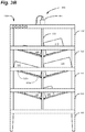
- the shelves 310 can be pivotally coupled to the bin 130 and can be mounted on a tilting mechanism 350.
- the tilting mechanism 350 can comprise, for example, a central shaft 355 pivotally coupled to each shelf 310.
- the central shaft 355 can be moved vertically using an actuator 360 such as, for example, a linear actuator, electric motor, or other means.
- the shelves 310 can have a first position ( Fig. 3A ) and a second position ( Fig. 3B ). As shown in Fig. 3B , in this first position, the inner portion 310a of the shelves 310 can be tilted down (or the outer portion 310b tilted up, depending on the mechanism) such that the merchandise 140, boxes, totes, and other items slide toward the center of the bin 130. This can prevent merchandise 140 from snagging on passing shelves 310 during transportation, for example, and can prevent items from falling off the shelves 310 due to bumps in the warehouse or minor collisions.
- the shelves 310 can be tilted into the second position, with the inner portion 310a of the shelves 310 tilted up in the middle (or, the outer portion 310b tilted down, depending on the mechanism) such that the inventory 140 slides to the outside of the bin 130.
- This can be useful, for example, to enable a picker to retrieve merchandise from the shelves 310, perform inventory counting or checks, and/or restock the shelves 310.
- the shelves 310 may also be placed in this position during warehouse inventory operations to enable passing robots 120 to more easily scan or capture images of merchandise, for example.
- Moving the shelves 310 between the first position and the second position can also assist in straightening, arranging, or securing the merchandise 140 on the shelves 310.
- the merchandise 140 which may be in boxes of varying sizes, slides into the outer 310b or inner 310a portion of the shelf 310, which can comprise a rim or stop, the boxes will tend to align and straighten.
- the shelves 310 can also be tilted at one or more intermediate positions to facilitate any of various operations or interactions with the bin 130.
- a particular intermediate position, for example, in which the shelves 310 are substantially level may be useful, for example, for long-term storage to minimize stresses on the shelves 310 and bins 130.
- each shelf 310, or compartment within a shelf may be controllably tilted independently of any other shelf or compartment via a corresponding tilting mechanism 350.
- one or more of the shelves 310, or compartments within the shelves can also include a pusher 375.
- the pusher 375 can comprise a linear actuator, for example, to move the merchandise within the shelves 310. This may be helpful, for example, to move very heavy boxes, for which the tilting of the shelf does not overcome the friction between the box and the shelf 310.
- the shelves 310 can remain in the first position (or in the intermediate substantially level position), for example, and the pusher 375 can move forward only the merchandise 140 to be picked. In other words, all of the merchandise 140 on the shelves can be in a retracted position, away from the edges of the shelves 310, while the merchandise 140 to be picked can be in the forward position.
- examples of the present disclosure can also comprise a system 400 for providing modular tools for use by any robot 120 in the system 400.
- the system 400 can comprise multiple base tools 405 with one or more components 410 (shown generically in dotted lines) mounted on a base 305.
- any robot 120 in the system 400 can act as a transport mechanism for any base tool 405.
- the bases 305 can be the same bases 305 used to support the shelving units 310. In other examples, the bases 305 can be purpose built for the components 410 mounted thereon.
- a robotic arm base tool 505 may require a structurally rigid base 305 to withstand the torque exerted on the base with the robotic arm 510.
- a floor base tool 805 may require a special shape to fit between or under bins 130.
- some base tools 405 may have special platforms to perform specific tasks, yet maintain the modularity of the interface between the robot 120 and the base tool 405.
- the robot 120 can be in direct control of the base tool 405.
- the sensors 210, 215, 250, additional input devices 230, and camera 225 on the robot 120 can be used in conjunction with a processor on the robot 120 to control the base tool 405 to perform various duties. So, for example, the robot 120 can receive a command from the management module 115 to perform a maintenance item, for example. The robot 120 can then retrieve the appropriate base tool 405, proceed to the location in the request, which can be located with one or more sensors 210, 215, 250, additional input devices 230, or the camera 225, for example, and then perform the requested task with the base tool 405.
- the robot 120 can then return the base tool 405 to a predetermined location (e.g., a storage locker) for later use.
- a predetermined location e.g., a storage locker
- the robot 120 can return the base tool 405 to a different location after use and the location for each base tool 405 can be stored by the management module 115 or the robot 120, for example.
- the robot 120 can use one or more base tools 405 in preprogrammed routines (e.g., to sweep the floor and then mop the floor).
- the robot 120 can simply carry, transport, and/or provide power to the base tool 405, while the management module 115 controls the base tool 405 remotely (e.g., via a transceiver in the base tool 405).
- the robot 120 can essentially act as a relay to enable the management module 115 to control the base tool 405 via a communication link in the robot 120.
- the base tool 405 can be autonomous or semi-autonomous and can comprise memory and a processor for performing certain activities.
- the base tool 405 may require no control (e.g., a sweeper) or power only (e.g., a mopper) and the robot 120 can simply move the base tool 405 in a suitable pattern to achieve the task.
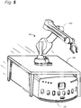
- the base tool 405 can comprise a robotic arm base tool 505 comprising a base 305 with a robotic arm 510. If the robot 120 identifies merchandise 140 on the floor of the warehouse 170 with one or more of its sensors (e.g., the camera 225), for example, the robot 120 can send an appropriate message to the management module 115. The management module 115 can then instruct the robot 120 (or another robot 120) to retrieve the robotic arm base tool 505, return to the location, and retrieve the merchandise 140 from the floor. In some examples, the robot 120 can then return the merchandise 140, for example, to an appropriate bin 130, a work station 150, or a dedicated "lost and found" bin 130.
- the robot 120 can then return the merchandise 140, for example, to an appropriate bin 130, a work station 150, or a dedicated "lost and found" bin 130.
- the robot 120 can be in direct control of the robotic arm 510.
- the sensors 210, 215, 250, additional input devices 230, and camera 225 on the robot 120 can be used in conjunction with a processor on the robot 120 to control the robotic arm base tool 505 to perform various duties. So, for example, the robot 120 can return to the location of the aforementioned merchandise 140 on the floor, locate it with one or more sensors 210, 215, 250, additional input devices 230, or the camera 225, and then pick up the merchandise 140 with the robotic arm 510. In some examples, the robot 120 can return the merchandise 140, for example, to the proper bin 130, a work station 150, or a central lost and found area or location.
- the robot 120 can use the robotic arm base tool 505 in preprogrammed routines (e.g., to sweep the floor).
- the robot 120 can carry the robotic arm base tool 505 and/or provide power, while the management module 115 controls the robotic arm base tool 505 (e.g., via a transceiver in the robotic arm base tool 505) or via a communication link in the robot 120.
- the robotic arm base tool 505 can be autonomous or semi-autonomous and can comprise memory and a processor for performing certain activities.
- the base tool 405 can comprise a camera base tool 605 comprising fixed or adjustable (e.g., telescoping or scissor-type) mount 610 with one or more imaging devices or cameras 615.
- the camera base tool 605 can be used to conduct inventory checks and/or counting in the warehouse 170. This can include checking the location and configuration of the bins 130 themselves and checking and/or counting the merchandise 140 in the bins 130.
- the camera base tool 605 can be used periodically to "patrol" the warehouse 170 to, for example, detect intruders, locate lost merchandise, and monitor operations.
- the camera base tool 605 can comprise one or more RFID scanners 615.
- the robot 120 can scan merchandise proximate the robot 120.
- RFID can be designed to have a relatively limited range (e.g. less than 10 feet)
- the RFID tags can be used to provide accurate inventory data, and can also provide data about the location of inventory.
- the merchandise 140 must be within the range of the RFID scanner 615 to be read, its position is known at least with the range of the RFID system (e.g., 10 feet).
- the scanner 615 can read tags on shelves on the robot 120 and any tags on other shelves within 10 feet.
- the robot 120 When the robot 120 is moving, however, the RFID tags for the merchandise 140 being carried by the robot 120 will stay in range, while tags located on other shelves will come in and out of range. As a result, the robot 120 (or management module 115) can determine what merchandise the robot 120 is carrying because it remains in range as the robot 120 moves. In addition, the management module 115 can also use speed and direction information from the robot 120 to further confirm the location of merchandise 140 as the robot 120 moves through the warehouse. In other words, the merchandise 140 may be located approximately between the position where it first came into range of the scanner 615 and the position where it went out of range of the scanner 615.
- the camera base tool 605 can also comprise infrared cameras 615, for example, to identify abnormal heat sources. This can help identify unwanted chemical reactions between adjacent products, for example, spontaneous combustion, and electrical problems, among other things.
- the cameras 615 can comprise many types of visible and invisible spectrum detectors, sensors, lasers, and other components.
- the base tool 405 can comprise a light tool 705 comprising one or more lights 715, or flashes.
- the lights 715 can enable the robot 120 to provide emergency lighting, for example, in case of a power failure.
- the light tool 705 can also provide illumination for repairs in the warehouse 170, for inventory image capture, or as a guide for an employee to a particular bin 130 (e.g., one that is broken).
- the lights 715 can be supported by a fixed or adjustable (e.g., telescoping) base 710.
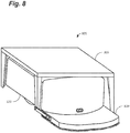
- the base tool 405 can also comprise a floor base tool 805.
- the floor base tool 805 can comprise tools for cleaning, painting, or otherwise maintaining the floors in the warehouse 170.
- the floor base tool 805 can comprise a floor cleaning attachment 810.
- the floor cleaning attachment 810 can comprise, for example, a broom attachment, a mop attachment, a buffer, a vacuum, or a waxer.
- the floor base tool 805 can enable the robots 120 to clean the warehouse floor without requiring a dedicated floor machine (e.g., an automated floor scrubber).
- the floor base tool 805 can comprise a tool for painting, striping, stickering, patching, or otherwise maintaining the floors in the warehouse 170 to allow the robots 120 to identify their locations while moving within the warehouse 170.
- the warehouse 170 floor can include magnetic or high visibility stripes, for example, painted or adhered to the floor for use by the robots 120 for guidance.
- markings can be provided to create exclusion zones to enable workers to walk through the warehouse 170 without interfering with, or being hit by, robots 120.
- the floor base tool 805 can be used to install and/or maintain the necessary markings to reduce maintenance costs and time.
- the base tools 405 can be controlled by the robot 120.
- the robotic arm base tool 505 can essentially provide the robot 120 with an arm for its use and can be controlled by the robot's 120 processor, in conjunction with the robot's sensors, scanners, and other input devices 210, 215, 230, 250 and/or camera 225.
- the robot 120 can include the functionality of a robot 120 with an arm, but without permanently installing a robotic arm 510 on the robot 120.
- each of the robots 120 can be used for multiple purposes, without specializing (e.g., a robot 120 with a permanently installed arm may not be able to pick up bins 130).
- the robot 120 can simply act as transportation, communication conduit, and/or power for the base tools 405 and the base tools 405 can be controlled directly (or via the robot 120) by the management module 115. So, for example, the management module 115 can command a robot 120 to retrieve the floor base tool 805 and then can provide turn-by-turn directions to the robot 120 to sweep or mop the warehouse 170, or a portion of the warehouse 170. In still other embodiments, processing can be shared between the management module 115 and the robot 120. In this configuration, the management module 115 can command the robot 120 to (1) retrieve the floor base tool 805 and (2) sweep or mop the warehouse 170. The robot 120 can then travel through the warehouse 170 using a preset pattern or a random pattern to cover the entire floor. In this manner, some of the management is controlled by the management module 115 (e.g., the timing and location of the cleaning), while the remainder of the management is controlled by the robot 120 (e.g., the pattern to follow, speed, etc.)
- the management module 115 e
- any robot 120 can use the camera base tool 605 for its own purposes (e.g., to provide a higher vantage point than the camera 225 on the robot 120) or can be used to capture images of all or part of the warehouse 170 using the camera base tool 605. As mentioned above, this can be used to conduct inventory checks and/or counting, for example, or for security or patrol purposes.
- the robot 120 can essentially act as a "dumb terminal," and can act based solely on commands from the management module 115. In this configuration, the management module 115 can command the robot 120 to go to the location of the camera base tool 605, pick it up, and then traverse the warehouse 170 in a pattern or route provided by the management module 115.
- the robot 120 can be autonomous or semi-autonomous and the management module 115 can simply send a command to the robot 120 to "conduct inventory check.”
- the robot 120 can then go to a preset location (or look for) the camera base tool 605, pick up the camera base tool 605, and the follow a preset or random pattern designed to cover the entire warehouse 170, or a portion of the warehouse 170.
- control and command can be shared by the robot 120 and the management module 115 with the management module 115 specifying a location to conduct inventory checks (e.g., the northwest quadrant of the warehouse 170) and the robot 120 determining the pattern required for same.
- the base tools 405 can be powered by power sources located on the base 305.
- the base 305 can include, for example, one or more batteries, capacitors, fuel cells, or other power sources to power one or more base tools 405.
- the base tools 405 can be powered by the power source on the robot 120.
- the lifting mechanism 235 and the base 305 can comprise complementary power and/or data communications connections.
- the lifting mechanism 235 can comprise one portion (e.g., male or female) of the connection(s) ( Fig. 9A ), while the other portion of the connections can be located on the base ( Fig. 9B ).
- the connections can comprise, for example, a ball and grid array 905, a three-pronged power socket 910, one or more USB connectors 915, or a round, multi-pin connector 920.
- data communications connections are possible including, but not limited to, isolated optical/fiber optic communications connections, short range RF (e.g., Bluetooth®), near field communications, automotive style connectors, and spring loaded connectors (e.g., "pogo" connectors).
- other types of power connections are possible including, for example, inductive power transfer, contact plates, and other contact and non-contact power transfer connections.
- data communications and/or power transfer can be provided by a ball and grid array 905.
- the ball grid array 905 can comprise a plurality of balls 905a on the lifting mechanism 235 and a plurality of hemispherical sockets 905b on the base 305 (or vice-versa).
- the balls 905a tend to self-align in the sockets 905b, less accuracy is required to make the connection.
- partial misalignment of the ball grid array 905 may be permissible, with the robot 120 identifying and mapping the correct power and communications pathways. In other words, if there are substantially more connections than are required, only partial alignment is necessary and the robot 120 can identify each connection and properly connect them.
- the connection between the base 305 and the robot 120 can include one or more low power connections (e.g., 5V DC for electronics) and one or more high power connections (e.g., 24V DC or 110V AC).
- the connection can also include one or more data communications connections between the base 305 and the robot 120.
- the data communications connections can comprise cable area network (CAN), LAN, and other wired connections.
- the data communications connections can comprise near field wireless connections, WLAN, or other wireless connections.
- all data communications connections can be wireless (e.g., WLAN) and all power connections can be wireless (e.g., inductive power transfer).
- the power and data communications connections can enable the robot 120 to provide power to the base tools 405 and bins 130, and vice-versa.
- these connections can also enable the robot 120 to control the base tools 405.
- the robotic arm base tool 505 can essentially become the "robot's 120 arm” when engaged (e.g., lifted) by the robot 120.
- any of the robots 120 can add the robotic arm base tool 505 when needed for improved functionality, and remove it when not needed to reduce weight and complexity.
- the connections can enable the robot 120 to control the cameras 315a, 615, scanners 315b, lights 315c, 715, sweeper/mopper 810, sensors, actuators and other base tools 405 as needed during use.
- the robot 120 can simply provide power and/or communications between the management module 115 and the base tool 405.
- the management module 115 can communicate directly with a transceiver on the base tool 405 to provide commands.
- the management module 115 can communicate with the base tool 405 via a transceiver on the robot 120, with the communication transmitted from the robot 120 to the base tool 405 via one or more of the connections.
- the base tools 405 and/or bins 130 can be self-contained and/or automated. In this manner, the robot 120 merely provides transportation for the base tool 405 or bin 130.
- the base tool 405 or bin 130 can be (1) powered by on-board power and controlled by the management module 115 or (2) powered by on-board power and act autonomously or semi-autonomously using on-board processors/logic.
- the lifting mechanism 235 can further comprise one or more weight or load sensors 925.
- the load sensors 925 can comprise, for examples, pressure transducers or strain gauges, and can provide information about the total weight of the load and/or the distribution of the load.
- the load sensors 925 can enable the robot 120 to sense when a load is unbalanced, for example, and either not fully pick up the load or pick the load up off center to prevent the load from toppling. In some embodiments, the load sensors 925 can also prevent the robot 120 from picking up a bin 130, for example, that exceeds its carrying capacity. This can reduce the risk of injury in the warehouse (e.g., due to falling loads) and reduce maintenance on the robots 120, among other things.
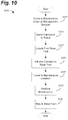
- examples of the present disclosure can also comprise a method 1000 for performing various maintenance operations with a robot and a base tool (or bin).
- the method 1000 can begin with a robot receiving a maintenance order or request from the management module, as shown at 1005.
- the maintenance request can comprise a number of tasks including, but not limited to, scanning the warehouse for obstructions or misplaced merchandise, capturing images or scans for inventory control, cleaning or otherwise maintaining the warehouse, and providing light to other maintenance projects.
- the management module can then send the command to a robot, as shown at 1010.
- the command can be sent to the nearest robot to the base tool, the nearest robot to the management module, or simply a robot that is not currently occupied.
- the instruction can include, for example, the task to be completed, the base tool required for the task, the location of the base tool and the task, and the estimated time of completion. So, for example, the command can instruct the robot to scan the entire warehouse with the camera base tool, that the camera tool is in the northwest corner of the warehouse, and that it will take the robot approximately one hour to travel up and down every aisle imaging every bin.
- the robot can then locate the base tool required for the job, as shown at 1015.
- each base tool can be returned to the same location or a different location after use and the location for each can be stored by the management module or the robot, for example.
- the base tool can comprise, for example, a camera base tool, a light base tool, or a robotic arm base tool.
- the system can also comprise a "Swiss army knife" base tool comprising two or more components on the same base (e.g., lights and cameras).
- the command can instruct the robot to locate a bin that includes additional components.
- the bin is used not to have merchandise picked or stowed, but to utilize the equipment (e.g., cameras and/or lights) installed on the bin.
- the command can comprise both instructions with respect to inventory to be picked from or stowed to the bin, and also instructions with respect to other equipment or components installed on the bin, to be performed either serially or in parallel.
- the robot can then lift and connect with the base tool, as shown at 1020.
- the connection can comprise power and/or data communications connections.
- the base tool is the robotic arm base tool
- the connection can include a power connection for the robot to power the arm and/or data communications connections for the robot (or the management module) to control the arm. This can enable the robot to move about the warehouse and remove obstructions from the floor of the warehouse, for example, or otherwise manipulate objects or items using the robotic arm.
- the robot can travel to the maintenance location, as shown at 1025.
- location information can be provided in the message from the management module.
- location information for certain tasks can be stored on the robot. If the task is to scan the entire warehouse for obstructions or clean the floor in the warehouse with the floor base tool, for example, the robot can follow a predetermined path up and down every aisle, or the robot can determine its path while performing the operations, with or without input/control by the management module.
- the robot can then perform the requested maintenance item, as shown at 1030.
- the robot can be substantially autonomous and can control the base tool (e.g., the robot can control the robotic arm base tool directly), the pattern, and the overall procedure of the maintenance item.
- the management module can control the robot as a tool, with the robot merely providing transportation, power, and/or a data communications link to the base tool.
- the management module can control certain portions of the maintenance item, while the robot can control other portions.
- the robot can return the base tool to its normal location or any other location, for example, as shown at 1035, and then resume other activities.
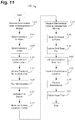
- embodiments of the present disclosure can also comprise a method 1100 of performing multiple tasks with the same robot.
- the method 1100 can begin with the management module receiving a request for product, for example, as shown at 1105.
- the management module can be connected to an e-commerce website, for example, and can receive requests directly.
- orders can be handled by an exterior website, call center, or application, and then sent to the management module.
- the management module can then send a message to a robot in the warehouse, as shown at 1110.
- the message can include the location of the bin containing requested merchandise, for example, the location of the work station where the merchandise will be picked, and details about the bin itself. If the bin contains additional electronics, for example, the message may also instruct the robot to utilize a camera or scanner on the bin once connected. The message may also instruct the robot to take the bin back to its original location, to another location, to maintenance, or to be restocked, for example, after the pick is completed.
- the management module can also send a message to the bin, as shown at 1115.
- the message may instruct the bin to turn on its indicators.
- the message may instruct the bin to activate a beacon to help the robot locate the bin.
- the bin may also include lights, cameras, scanners, sensors, actuators or other equipment that should be activated prior to the arrival of the robot.
- the bin may not have on-board power and the management module may send messages only after the bin is attached to the robot.
- the robot can then locate the bin in the warehouse, as shown at 1120.
- location information can be included in the message to the robot, or can be stored onboard the robot.
- the robot can use GPS, cellular location services, a homing beacon, visual identifiers, location identifiers, tracks and/or slots in the floor, or other suitable means to travel from its current location to the bin.
- the robot can also scan the bin to ensure it has located the correct bin.
- lifting the bin can also establish one or more electrical connections including, for example, power and/or data communications between the bin and the robot. This can enable the robot to transfer power to any onboard power source for the bin, or vice versa.
- the electrical connections can also enable the robot to utilize, transmit, and/or download data from any electrical equipment on the bin. In some examples, the electrical equipment on the bin can only be powered when the robot is connected to the bin. As mentioned above, this can enable the robot to scan or image the warehouse as it travels from the bin location to the work station and back, among other operations or tasks.
- an employee can remove the requested merchandise from the bin, as shown at 1130.
- the picker can then manually activate (or deactivate) the pick switch on the bin, as shown at 1135.
- a laser scanner or camera for example, can detect the pick and activate the pick switch on the bin.
- the pick switch can turn off the indicators on the bin.
- the pick switch can also send a message from the bin and/or the robot to the management module that the pick is complete.
- the pick switch can deactivate the electrical equipment on the bin. The robot can then return the bin to its original location, another location, maintenance, or restocking, as necessary, as shown at 1140.
- the same robot 120 can then receive a request to perform a maintenance task from the management module, as shown at 1145.
- the maintenance request can comprise a number of tasks including, but not limited to, scanning the warehouse for obstructions or misplaced merchandise, capturing images, pictures or scans for inventory control, sensing characteristics of the environment, and providing light to other maintenance projects.
- the management module can then send the command to a robot, as shown at 1150.
- the command can be sent to the robot nearest to the base tool, the robot nearest to the management module, or simply a robot that is not currently occupied.
- the instruction can include, for example, the task to be completed, the base tool required for the task, the location of the base tool and the task, and the estimated time of completion. So, for example, the command can instruct the robot to scan the entire warehouse with the camera base tool, that the camera tool is in the northwest comer of the warehouse, and that it will take the robot approximately one hour to travel up and down every aisle imaging every bin.
- the robot can then locate the base tool required for the job, as shown at 1155.
- each base tool can be returned to the same location or another location after use and the location for each can be stored on the robot, for example.
- the base tool can comprise, for example, a camera base tool, a light base tool, or a robotic arm base tool.
- the system can also comprise a "Swiss army knife" base tool comprising two or more components on the same base (e.g., lights, sensors, actuators, and cameras).
- the command can instruct the robot to locate a bin that includes additional components. In this case, the bin is used not to have merchandise picked, but to utilize the equipment (e.g., cameras, scanners, sensors, actuators and/or lights) installed on the bin.
- connection can comprise power and/or data communications connections.
- the connection can include a power connection for the robot to power the arm and/or data communications connections for the robot (or the management module) to control the arm. This can enable the robot to go into the warehouse and remove obstructions from the floor of the warehouse, for example.
- the robot can travel to the maintenance location, as shown at 1165.
- location information can be provided in the message from the management module.
- location information for certain tasks can be stored on the robot. If the task is to scan the entire warehouse for obstructions or clean the floor in the warehouse with the floor base tool, for example, the robot can follow a predetermined path up and down every aisle.
- the robot can then perform the requested maintenance item, as shown at 1170.
- the robot can be substantially autonomous and can control the base tool (e.g., the robot can control the robotic arm base tool directly), the pattern, and the overall procedure of the maintenance item.
- the management module can control the robot as a tool, with the robot merely providing transportation, power, and/or a data communications link to the base tool.
- the management module can control certain portions of the maintenance item, while the robot can control other portions.
- the robot can return the base tool to its storage location or another location (or to maintenance for upkeep), as shown at 1175, and then move on to the next task (e.g., another pick or another maintenance task).
- the management module can command the robot to "illuminate aisle four," for example, to provide illumination for maintenance workers.
- the robot can then retrieve the light base tool, either from a fixed location or by locating it visually or using a homing beacon, for example, and then travel to aisle four, which may be a location stored in the robot's memory and activate the light base tool.
- the robot can then return the light base tool (or other base tool 405 or bin 130) to its original, or other appropriate, location.
- the base tool 405 or bin 130 can have a fixed "home" location.
- the management module can send a second command for the robot to return the base tool to a particular location.
- any robot can use any base tool, and a single robot can use one base tool, return or disconnect it, and then use another base tool.
- the management module 115 can control the robot 120 and the base tool 405 directly.
- the robot 120 can receive step-by-step instructions from the management module 115 to go to a first location, pick up a base tool 405, and then travel to a second location.
- the management module 115 can then send commands to the base tool 405 (either directly or via the robot 120) to perform one or more operations.
- the management module 115 can then send step-by-step instructions to the robot 120 to return to the first location and return (e.g., put down) the base tool 405.
- other load or control sharing combinations between the robots 120 and the management module 115 could be used.
- examples of the present disclosure are not so limited.
- a system of modular tools for warehouse robots is disclosed, other tools and other robots could be selected without departing from the spirit of the disclosure.
- the location and configuration used for various features of examples of the present disclosure such as, for example, the location and configuration of bins, the types of robots, and the layout of the warehouse can be varied according to a particular warehouse, inventory, or robot that requires a slight variation due to, for example, size or construction covenants, the type of robot required, or weight or power constraints.
Landscapes
- Engineering & Computer Science (AREA)
- Business, Economics & Management (AREA)
- Economics (AREA)
- Mechanical Engineering (AREA)
- Human Resources & Organizations (AREA)
- Quality & Reliability (AREA)
- Finance (AREA)
- Development Economics (AREA)
- Theoretical Computer Science (AREA)
- Entrepreneurship & Innovation (AREA)
- Robotics (AREA)
- Marketing (AREA)
- Operations Research (AREA)
- Accounting & Taxation (AREA)
- Strategic Management (AREA)
- Tourism & Hospitality (AREA)
- Physics & Mathematics (AREA)
- General Business, Economics & Management (AREA)
- General Physics & Mathematics (AREA)
- Computer Networks & Wireless Communication (AREA)
- Warehouses Or Storage Devices (AREA)
- Manipulator (AREA)
Claims (11)
- System, umfassend:
einen Roboter (120), umfassend:ein Antriebssystem, um den Roboter (120) innerhalb einer Umgebung zu bewegen;ein Hebewerk (235), mit einer zurückgezogenen Position und einer ausgefahrenen Position, zur Verbindung mit einer oder mit mehreren Komponenten des Systems innerhalb der Umgebung; undeinen oder mehrere Anschlüsse, zur Stromversorgung oder zum Bereitstellen von Kommunikationen zwischen dem Roboter (120) und der einen oder den mehreren Komponenten des Systems; undein erstes Basiswerkzeug (405, 505, 605, 805), umfassend:
eine Basis (305), welche einen oder mehrere erste komplementäre Anschlüsse zur Stromversorgung oder zum Bereitstellen von Kommunikationen zwischen dem Basiswerkzeug (405, 505, 605, 805) und dem Roboter (120) umfasst; dadurch gekennzeichnet, dass das erste Basiswerkzeug (405, 505, 605, 805) umfasst:
ein Werkzeug, welches auf der Basis (305) angeordnet ist und mit mindestens einem des einen oder der mehreren ersten komplementären Anschlüsse gekoppelt ist; und dass das System ferner umfasst:
ein zweites unterschiedliches Basiswerkzeug, welches eine Regaleinheit (310) umfasst, umfassend:einen oder mehrere zweite komplementäre Anschlüsse, zur Stromversorgung oder um Daten zwischen dem zweiten Basiswerkzeug und dem Roboter (120) zu übertragen;ein oder mehrere Regale, wobei jedes Regal einen inneren Abschnitt (310a) und einen äußeren Abschnitt (310b) zum Aufbewahren von Lagerartikeln (140) umfasst; undeine oder mehrere elektronische Komponenten, welche mit dem einen oder den mehreren zweiten komplementären Anschlüssen verbunden sind, wobei die eine oder die mehreren elektronischen Komponenten umfassen:eine oder mehrere Leuchten zum Anzeigen, dass die Regaleinheit (310) eine ausstehende Entnahme aufweist; undeinen Entnahmeschalter (330), welcher konfiguriert ist, um die eine oder die mehreren Leuchten auszuschalten und ein Signal an ein Verwaltungsmodul (115) zu initiieren, welches die Vervollständigung der Entnahme anzeigt;wobei der eine oder die mehreren Anschlüsse und der eine oder die mehreren ersten komplementären Anschlüsse oder der eine oder die mehreren zweiten komplementären Anschlüsse zwischen dem Roboter (120) und dem ersten Basiswerkzeug (405, 505, 605, 805) oder dem zweiten Basiswerkzeug jeweils in der ausgefahrenen Position verbunden sind;wobei der eine oder die mehreren Anschlüsse und der eine oder die mehreren ersten komplementären Anschlüsse oder der eine oder die mehreren zweiten komplementären Anschlüsse zwischen dem Roboter (120) und dem ersten Basiswerkzeug (405, 505, 605, 805) oder dem zweiten Basiswerkzeug jeweils in der zurückgezogenen Position unterbrochen sind;wobei der Roboter (120) sich mit dem ersten Basiswerkzeug (405, 505, 605, 805) verbindet, um einen ersten Vorgang unter Verwendung des ersten Basiswerkzeugs (405, 505, 605, 805) auszuführen; undwobei der Roboter (120) sich mit dem zweiten Basiswerkzeug verbindet, um einen zweiten unterschiedlichen Vorgang unter Verwendung des zweiten Basiswerkzeugs auszuführen. - System nach Anspruch 1, wobei die Basis (305) eine erste Basis ist, und das Werkzeug ein erstes Werkzeug ist, und ferner umfassend:ein drittes unterschiedliches Basiswerkzeug (405, 505, 605, 805), umfassend:eine dritte Basis, welche einen oder mehrere dritte komplementäre Anschlüsse umfasst, zur Stromversorgung oder zum Bereitstellen von Kommunikationen zwischen dem Basiswerkzeug (405, 505, 605, 805) und dem Roboter (120); undein unterschiedliches Werkzeug, welches auf der dritten Basis (305) angeordnet ist und mit mindestens einem des einen oder der mehreren dritten komplementären Anschlüsse verbunden ist;wobei der Roboter (120) sich mit dem dritten Basiswerkzeug (405, 505, 605, 805) verbindet, um einen dritten unterschiedlichen Vorgang auszuführen.
- System nach Anspruch 1, wobei das erste Basiswerkzeug (405, 505, 605, 805) ein robotisches Armbasiswerkzeug (505) umfasst, welches einen robotischen Arm (510) umfasst, welcher konfiguriert ist, um mindestens eines aus Greifen, Bewegen, Manipulieren oder Heben von Objekten ausführt.
- System nach Anspruch 1, wobei das erste Basiswerkzeug (405, 505, 605, 805) ein Kamerabasiswerkzeug (605) umfasst, welches eine oder mehrere Kameras (615) umfasst, welche konfiguriert sind, um ein oder mehrere Bilder der Umgebung aufzunehmen.
- System nach Anspruch 1, wobei das erste Basiswerkzeug (405, 505, 605, 805) ein Lichtbasiswerkzeug umfasst, welches eine oder mehrere Lichtquellen umfasst, welche konfiguriert sind, um ein in der Nähe des Roboters liegendes Gebiet zu beleuchten.
- System nach Anspruch 1, wobei das erste Basiswerkzeug (405, 505, 605, 805) ein oder mehrere Bodenwerkzeuge (805) umfasst, welche konfiguriert sind, um mindestens einen Abschnitt eines Bodens der Umgebung instand zu halten.
- System nach Anspruch 2,
wobei der eine oder die mehreren Anschlüsse und der eine oder die mehreren ersten komplementären Anschlüsse, der eine oder die mehreren zweiten komplementären Anschlüsse, oder der eine oder die mehreren dritten komplementären Anschlüsse zwischen dem Roboter (120) und dem ersten Basiswerkzeug (405, 505, 605, 805), dem zweiten Basiswerkzeug oder dem dritten Basiswerkzeug jeweils in der ausgefahrenen Position verbunden sind;
wobei der eine oder die mehreren Anschlüsse und der eine oder die mehreren ersten komplementären Anschlüsse, der eine oder die mehreren zweiten komplementären Anschlüsse, oder der eine oder die mehreren dritten komplementären Anschlüsse zwischen dem Roboter (120) und dem ersten Basiswerkzeug (405, 505, 605, 805), dem zweiten Basiswerkzeug oder dem dritten Basiswerkzeug jeweils in der zurückgezogenen Position unterbrochen sind. - System nach Anspruch 1, wobei die Regaleinheit (310) ferner einen oder mehrere Aktuatoren zum Bewegen eines ersten Regals unter dem einen oder den mehreren Regalen zwischen einer ersten Position und einer zweiten Position umfasst; wobei, in der ersten Position, das erste Regal so geneigt ist, dass der innere Abschnitt (310a) des ersten Regals sich unterhalb des äußeren Abschnitts des ersten Regals befindet, um zu veranlassen, dass die Lagerartikel (140) auf dem ersten Regal sich in eine zentrale Position auf der Regaleinheit (310) bewegen, und wobei, in der zweiten Position, das erste Regal so geneigt ist, dass der innere Abschnitt (310a) des ersten Regals sich oberhalb des äußeren Abschnitts (310b) des ersten Regals befindet, um zu veranlassen, dass die Lagerartikel (140) auf dem ersten Regal sich in eine äußere Position auf der Regaleinheit (310) bewegen.
- System nach Anspruch 1, wobei der Entnahmeschalter (330) einen Laser-Scanner (315b) umfasst, um die Entnahme eines oder mehrerer Lagerartikel (140) aus der Regaleinheit (310) zu erfassen, und wobei der Laser-Scanner (315b) ferner das Signal an das Verwaltungsmodul (115) initiiert, welches die Vervollständigung der Entnahme anzeigt.
- System nach Anspruch 1, wobei ein erstes Regal unter dem einen oder die mehreren Regalen einen Stößel (375) umfasst, um Lagerartikel (140) zwischen dem inneren Abschnitt (310a) des ersten Regals und dem äußeren Abschnitt (310b) des ersten Regals zu bewegen.
- System nach Anspruch 1, wobei der Entnahmeschalter (330) einen Funkfrequenzidentifizierungs-(RFID)-Scanner (615) umfasst, um die Entnahme eines oder mehrerer Lagerartikel (140) aus der Regaleinheit (310) zu erfassen, und wobei der RFID-Scanner (615) ferner das Signal an das Verwaltungsmodul (115) initiiert, welches die Vervollständigung der Entnahme anzeigt.
Applications Claiming Priority (2)
| Application Number | Priority Date | Filing Date | Title |
|---|---|---|---|
| US14/622,559 US9656806B2 (en) | 2015-02-13 | 2015-02-13 | Modular, multi-function smart storage containers |
| PCT/US2016/015739 WO2016130338A1 (en) | 2015-02-13 | 2016-01-29 | Modular, multi-function smart storage containers |
Publications (2)
| Publication Number | Publication Date |
|---|---|
| EP3256290A1 EP3256290A1 (de) | 2017-12-20 |
| EP3256290B1 true EP3256290B1 (de) | 2020-04-08 |
Family
ID=55443314
Family Applications (1)
| Application Number | Title | Priority Date | Filing Date |
|---|---|---|---|
| EP16706930.1A Active EP3256290B1 (de) | 2015-02-13 | 2016-01-29 | Modulare intelligente multifunktionsaufbewahrungsbehälter |
Country Status (5)
| Country | Link |
|---|---|
| US (1) | US9656806B2 (de) |
| EP (1) | EP3256290B1 (de) |
| JP (1) | JP6542903B2 (de) |
| CN (1) | CN107250004B (de) |
| WO (1) | WO2016130338A1 (de) |
Cited By (4)
| Publication number | Priority date | Publication date | Assignee | Title |
|---|---|---|---|---|
| IT202200020298A1 (it) | 2022-10-03 | 2024-04-03 | Cmc Spa | Metodo per prelevare articoli in un magazzino e magazzino |
| IT202200020301A1 (it) | 2022-10-03 | 2024-04-03 | Cmc Spa | Unita' di stoccaggio di articoli semovente o trasportabile, magazzino e metodo |
| US12291439B2 (en) | 2019-10-29 | 2025-05-06 | Ims Gear Se & Co. Kgaa | Driverless transport device and driverless transport system for transporting objects, and method for operating a driver-less transport device and a driverless transport system for transporting objects |
| EP4480862B1 (de) * | 2018-06-22 | 2025-10-15 | Daifuku Co., Ltd. | Artikeltransportfahrzeug |
Families Citing this family (191)
| Publication number | Priority date | Publication date | Assignee | Title |
|---|---|---|---|---|
| US9139363B2 (en) | 2013-03-15 | 2015-09-22 | John Lert | Automated system for transporting payloads |
| US10084329B2 (en) * | 2014-02-28 | 2018-09-25 | Nrg Energy, Inc. | Power pack vending apparatus, system, and method of use for charging power packs with biased locking arrangement |
| US9174800B1 (en) * | 2014-03-25 | 2015-11-03 | Amazon Technologies, Inc. | Verifying bin content in a materials handling facility |
| FR3021144B1 (fr) * | 2014-03-26 | 2016-07-15 | Bull Sas | Procede de gestion des equipements d'un centre de donnees |
| US20190325379A1 (en) * | 2014-10-24 | 2019-10-24 | Fellow, Inc. | Intelligent inventory management using cleaning machines |
| US10845822B2 (en) * | 2014-10-31 | 2020-11-24 | Clearpath Robotics Inc. | Systems and methods for utilizing fleets of robots |
| US9606544B2 (en) * | 2014-10-31 | 2017-03-28 | Clearpath Robotics, Inc. | System, computing device and method for unmanned vehicle fleet control |
| US9875503B2 (en) | 2015-03-06 | 2018-01-23 | Wal-Mart Stores, Inc. | Method and apparatus for transporting a plurality of stacked motorized transport units |
| US20180099846A1 (en) | 2015-03-06 | 2018-04-12 | Wal-Mart Stores, Inc. | Method and apparatus for transporting a plurality of stacked motorized transport units |
| WO2016142794A1 (en) | 2015-03-06 | 2016-09-15 | Wal-Mart Stores, Inc | Item monitoring system and method |
| US12366043B2 (en) | 2015-03-06 | 2025-07-22 | Walmart Apollo, Llc | Overriding control of motorized transport unit systems, devices and methods |
| US12084824B2 (en) | 2015-03-06 | 2024-09-10 | Walmart Apollo, Llc | Shopping facility assistance systems, devices and methods |
| CN107683253B (zh) * | 2015-04-09 | 2019-12-10 | 格雷奥朗佩特有限公司 | 升降设备 |
| US11203486B2 (en) | 2015-06-02 | 2021-12-21 | Alert Innovation Inc. | Order fulfillment system |
| CN108290685B (zh) | 2015-06-02 | 2021-03-02 | 阿勒特创新股份有限公司 | 存取系统 |
| US11142398B2 (en) | 2015-06-02 | 2021-10-12 | Alert Innovation Inc. | Order fulfillment system |
| US10118296B1 (en) * | 2015-09-10 | 2018-11-06 | X Development Llc | Tagged robot sensor data |
| CN109414819A (zh) * | 2016-01-08 | 2019-03-01 | 4D空间天才股份有限公司 | 用于自动化图像获取的机器人 |
| EP3192616B1 (de) | 2016-01-14 | 2024-09-25 | Jungheinrich AG | Roboter zum aufnehmen und transportieren von objekten und verfahren zur verwendung solch eines roboters |
| CN105522583B (zh) * | 2016-01-25 | 2017-10-31 | 南京大学 | 一种基于rfid技术的自动式图书智能盘点上架机器人 |
| CA2961938A1 (en) | 2016-04-01 | 2017-10-01 | Wal-Mart Stores, Inc. | Systems and methods for moving pallets via unmanned motorized unit-guided forklifts |
| AT15289U1 (de) * | 2016-06-14 | 2017-05-15 | Knapp Ag | Kommissioniersystem mit einem Transportroboter zum Unterfahren von Einzelregalen |
| KR102565501B1 (ko) * | 2016-08-01 | 2023-08-11 | 삼성전자주식회사 | 로봇 청소기, 냉장고, 용기 이송 시스템 및 로봇 청소기를 이용한 용기의 이송 및 회수 방법 |
| US10317119B2 (en) * | 2016-08-25 | 2019-06-11 | Amazon Technologiess, Inc. | Transportable climate-controlled units for fulfillment of perishable goods |
| US10012992B2 (en) * | 2016-09-15 | 2018-07-03 | Amazon Technologies, Inc. | Integrated obstacle detection and payload centering sensor system |
| US20220132229A1 (en) * | 2016-10-10 | 2022-04-28 | Telescent, Inc. | Incrementally scalable, two-tier system of robotic, fiber optic interconnect units enabling any-to-any connectivity |
| WO2018071341A2 (en) * | 2016-10-10 | 2018-04-19 | Telescent Inc. | System of large scale robotic fiber cross-connects using multi-fiber trunk reservation |
| US10987804B2 (en) * | 2016-10-19 | 2021-04-27 | Fuji Xerox Co., Ltd. | Robot device and non-transitory computer readable medium |
| US10528061B2 (en) * | 2016-10-25 | 2020-01-07 | Amazon Technologies, Inc. | Robotic ad hoc network |
| JP7137562B2 (ja) | 2016-11-17 | 2022-09-14 | アラート イノヴェイション インコーポレイテッド | 自動化サービス小売システム及び方法 |
| CN110100256A (zh) | 2016-11-29 | 2019-08-06 | 阿勒特创新股份有限公司 | 自动化零售供应链和存货管理系统 |
| JP6840530B2 (ja) * | 2016-12-22 | 2021-03-10 | 東芝テック株式会社 | 画像処理装置及び画像処理方法 |
| US10585440B1 (en) | 2017-01-23 | 2020-03-10 | Clearpath Robotics Inc. | Systems and methods for using human-operated material-transport vehicles with fleet-management systems |
| CN108357886A (zh) * | 2017-01-26 | 2018-08-03 | 菜鸟智能物流控股有限公司 | 物品拣选方法及相关设备 |
| US10625941B2 (en) | 2017-01-30 | 2020-04-21 | Walmart Apollo, Llc | Distributed autonomous robot systems and methods |
| CA3050727A1 (en) * | 2017-01-30 | 2018-08-02 | Walmart Apollo, Llc | Distributed autonomous robot systems and methods with rfid tracking |
| WO2018140722A1 (en) | 2017-01-30 | 2018-08-02 | Walmart Apollo, Llc | Distributed autonomous robot interfacing systems and methods |
| GB2573902B (en) | 2017-01-30 | 2021-11-24 | Walmart Apollo Llc | Systems and methods for distributed autonomous robot interfacing using live image feeds |
| EP4044083B1 (de) * | 2017-02-24 | 2023-09-13 | Walmart Apollo, Llc | System und verfahren zur inventarverwaltung |
| CN114873119B (zh) | 2017-03-20 | 2023-10-31 | 伯克希尔格雷营业股份有限公司 | 用于处理包括移动矩阵载体系统的物体的系统和方法 |
| ES2973481T3 (es) | 2017-03-23 | 2024-06-20 | Berkshire Grey Operating Company Inc | Sistema y método para procesar objetos, incluyendo portadores matriciales móviles automatizados |
| CN110662707B (zh) | 2017-03-23 | 2021-12-14 | 伯克希尔格雷股份有限公司 | 用于处理包括自动移动矩阵箱的物体的系统和方法 |
| US10265844B2 (en) * | 2017-03-24 | 2019-04-23 | International Business Machines Corporation | Creating assembly plans based on triggering events |
| US20220012780A1 (en) | 2017-04-05 | 2022-01-13 | State Farm Mutual Automobile Insurance Company | Systems and methods for estimating vehicle value via blockchain |
| US10384541B2 (en) * | 2017-05-19 | 2019-08-20 | UBTECH Robotics Corp. | Laser radar module and robot |
| US10860750B2 (en) * | 2017-06-15 | 2020-12-08 | Sap Se | Model driven layout design for robotics warehouse |
| JP6923383B2 (ja) * | 2017-07-27 | 2021-08-18 | 株式会社日立物流 | ピッキングロボットおよびピッキングシステム |
| CN114789867B (zh) | 2017-10-27 | 2024-05-24 | 伯克希尔格雷营业股份有限公司 | 用于处理物体的包括移动矩阵载体系统的系统和方法 |
| NO344326B1 (en) * | 2017-11-07 | 2019-11-04 | Autostore Tech As | Storage system comprising a charging station Assembly and a method for exchanging a power source of a vehicle operating in a storage system. |
| US11396424B2 (en) | 2017-11-14 | 2022-07-26 | Hai Robotics Co., Ltd. | Handling robot |
| US12006143B2 (en) * | 2017-11-14 | 2024-06-11 | Hai Robotics Co., Ltd. | Handling robot |
| US11465840B2 (en) | 2017-11-14 | 2022-10-11 | Hai Robotics Co., Ltd. | Handling robot |
| US12103771B2 (en) | 2017-11-14 | 2024-10-01 | Hai Robotics Co., Ltd. | Handling robot |
| KR102385397B1 (ko) * | 2017-11-14 | 2022-04-14 | 하이 로보틱스 씨오., 엘티디. | 운반 로봇 및 운반 로봇에 기반한 픽업 방법 |
| US12330870B2 (en) | 2017-11-14 | 2025-06-17 | Hai Robotics Co., Ltd. | Handling robot |
| JP6705793B2 (ja) * | 2017-11-28 | 2020-06-03 | ファナック株式会社 | 加工システム |
| US10514700B2 (en) * | 2017-12-15 | 2019-12-24 | Walmart Apollo, Llc | System and method for managing a vehicle storage area |
| DE102017131294A1 (de) * | 2017-12-23 | 2019-06-27 | Brose Fahrzeugteile Gmbh & Co. Kommanditgesellschaft, Coburg | Materialbereitstellungssystem für eine Fertigungsanlage |
| CN108045754B (zh) * | 2018-01-02 | 2024-01-26 | 上海木爷机器人技术有限公司 | 一种储存柜及可对储存柜进行充电的运输机器人 |
| CN108107862B (zh) * | 2018-01-16 | 2022-04-12 | 北京极智嘉科技股份有限公司 | 集存储拣选于一体的物品运送系统及方法 |
| WO2019140536A1 (en) | 2018-01-22 | 2019-07-25 | Clearpath Robotics Inc. | Systems and methods for measuring fleets of self-driving industrial vehicles |
| US11235778B2 (en) | 2018-01-24 | 2022-02-01 | Clearpath Robotics Inc. | Systems and methods for maintaining vehicle state information |
| WO2019153082A1 (en) | 2018-02-07 | 2019-08-15 | Clearpath Robotics Inc. | Communication systems for self-driving vehicles, and methods of providing thereof |
| WO2019159319A1 (ja) * | 2018-02-16 | 2019-08-22 | 株式会社Fuji | 基板作業システム |
| TR201802463A2 (tr) * | 2018-02-21 | 2018-03-21 | Teknopalas Yueksek Teknoloji Sist San Ve Tic Ltd Sti | Mobi̇l raf denetleme platformu |
| US11173605B2 (en) * | 2018-02-26 | 2021-11-16 | dogugonggan Co., Ltd. | Method of controlling mobile robot, apparatus for supporting the method, and delivery system using mobile robot |
| US10843333B2 (en) | 2018-03-05 | 2020-11-24 | Berkshire Grey, Inc. | Systems and methods for processing objects, including automated re-circulating processing stations |
| AT520958A1 (de) | 2018-03-09 | 2019-09-15 | Tgw Logistics Group Gmbh | Robotersystem mit an Warentypen angepassten Bewegungsabläufen und Betriebsverfahren hierfür |
| AT521112A1 (de) | 2018-03-09 | 2019-10-15 | Tgw Logistics Group Gmbh | Robotersystem zum Greifen einer Ware in einem Lager- und Kommissioniersystem und Betriebsverfahren hierfür |
| AT520945A1 (de) | 2018-03-09 | 2019-09-15 | Tgw Logistics Group Gmbh | Kommissionierstation und Verfahren zum automatischen Kommissionieren von Waren |
| AT520957A1 (de) * | 2018-03-09 | 2019-09-15 | Tgw Logistics Group Gmbh | Robotersystem zur Prüfung eines Laderaums eines Ladehilfsmittels in einem Lager- und Kommissioniersystem und Betriebsverfahren hierfür |
| US11491642B2 (en) * | 2018-03-14 | 2022-11-08 | Fedex Corporate Services, Inc. | Methods of performing a dispatched store-to-consumer logistics operation for an ordered item and using a modular autonomous bot apparatus assembly and a dispatch server |
| TR201803789A2 (tr) * | 2018-03-16 | 2018-05-21 | Huenkar Dirik | Robotlar i̇le markette alişveri̇ş yapmak |
| US10902880B2 (en) * | 2018-03-23 | 2021-01-26 | Amazon Technologies, Inc. | Moveable motor and cover for mobile drive unit turntable |
| WO2019195076A1 (en) * | 2018-04-04 | 2019-10-10 | Walmart Apollo, Llc | Cold-chain compliant item storage cart system |
| US20190320834A1 (en) * | 2018-04-23 | 2019-10-24 | Walmart Apollo, Llc | Modular automated locker systems for storing and dispensing customer orders |
| CN108544534B (zh) * | 2018-04-24 | 2020-10-27 | 泰州市元和达电子科技有限公司 | 一种基于机器人的隐藏式智能物品放置系统 |
| CN108423355A (zh) * | 2018-04-26 | 2018-08-21 | 北京极智嘉科技有限公司 | 搬运系统和搬运方法 |
| EP3786085B1 (de) | 2018-04-26 | 2024-05-01 | Beijing Geekplus Technology Co., Ltd. | Fördersystem und förderverfahren mit einem ersten roboter und einem zweiten roboter |
| AU2018203338B2 (en) * | 2018-05-14 | 2020-06-25 | Deutsche Post Ag | Autonomous robot vehicle |
| US11235818B2 (en) * | 2018-05-31 | 2022-02-01 | A9.com | Universal anchor points for mobile robots |
| US11572231B2 (en) | 2018-06-12 | 2023-02-07 | Autostore Technology AS | Storage system with modular container handling vehicles |
| WO2019238703A1 (en) * | 2018-06-12 | 2019-12-19 | Autostore Technology AS | Storage system with modular container handling vehicles |
| JP7065287B2 (ja) * | 2018-06-22 | 2022-05-12 | パナソニックIpマネジメント株式会社 | 移動装置、搬送装置、移動システム、及び移動方法 |
| JP7199848B2 (ja) * | 2018-06-27 | 2023-01-06 | 株式会社日立インダストリアルプロダクツ | ピッキング支援方法 |
| US10894664B1 (en) * | 2018-06-29 | 2021-01-19 | Amazon Technologies, Inc. | Mobile sortation and delivery of multiple items |
| US11097897B1 (en) * | 2018-07-13 | 2021-08-24 | Vecna Robotics, Inc. | System and method of providing delivery of items from one container to another container via robot movement control to indicate recipient container |
| CN108828572A (zh) * | 2018-08-24 | 2018-11-16 | 杭州物必连科技有限公司 | 一种物联网机器人、仓库货物定位系统及定位方法 |
| DE102019200661A1 (de) | 2018-08-30 | 2020-03-05 | Deckel Maho Pfronten Gmbh | Werkzeugmaschine zum spanenden bearbeiten eines werkstücks |
| JP7028114B2 (ja) * | 2018-09-07 | 2022-03-02 | オムロン株式会社 | 自動搬送システムおよび荷台 |
| CN109271920A (zh) * | 2018-09-12 | 2019-01-25 | 上海了物网络科技有限公司 | 支持物品识别的视觉系统及方法与介质 |
| TWI689877B (zh) | 2018-09-14 | 2020-04-01 | 財團法人工業技術研究院 | 揀貨及補貨方法、揀貨台車以及揀貨及補貨系統 |
| CN109051487A (zh) * | 2018-09-17 | 2018-12-21 | 北海华源电子有限公司 | 电子产品货架智能管理系统 |
| US20200090803A1 (en) * | 2018-09-17 | 2020-03-19 | Supporting Initiatives to Redistribute Unused Medicine (SIRUM) | Chaotic storage of prescription medications |
| US11305936B2 (en) | 2018-09-28 | 2022-04-19 | Autoguide, LLC | Commercial logistic facility, configurable modular robotic autonomous guided vehicle, and method therefor |
| CN110962101B (zh) * | 2018-09-29 | 2021-09-14 | 西门子(中国)有限公司 | 工业机器人搬运装置、系统、方法和机器可读介质 |
| CN109436639A (zh) * | 2018-10-12 | 2019-03-08 | 桐城市立行电子科技有限公司 | 一种搬运用仓储机器人 |
| CN109292334A (zh) * | 2018-10-12 | 2019-02-01 | 桐城市立行电子科技有限公司 | 一种用于快递存储转运的机器人 |
| DE102018217471A1 (de) | 2018-10-12 | 2020-04-16 | Krones Ag | Modulares Robotersystem für eine Behälterverarbeitungsanlage |
| CN109335436A (zh) * | 2018-10-22 | 2019-02-15 | 刘晗 | 智能周转仓储系统及其取放件方法 |
| US11623826B2 (en) * | 2018-11-09 | 2023-04-11 | Walmart Apollo, Llc | System having robotic workstation |
| JP2020082233A (ja) * | 2018-11-19 | 2020-06-04 | 株式会社Ihi | ロボット用架台、搬送システム及び搬送方法 |
| CN109399041B (zh) | 2018-11-19 | 2023-04-21 | 炬星科技(深圳)有限公司 | 基于机器人的随机仓储方法、装置及电子设备与存储介质 |
| US11520337B2 (en) | 2018-12-11 | 2022-12-06 | Autonomous Shelf, Inc. | Mobile inventory transport unit and autonomous operation of mobile inventory transportation unit networks |
| US11383394B1 (en) * | 2018-12-11 | 2022-07-12 | Amazon Technologies, Inc. | Extensible mast for an autonomous mobile device |
| US11226067B1 (en) | 2018-12-11 | 2022-01-18 | Amazon Technologies, Inc. | Mechanism for sequenced deployment of a mast |
| US11396266B1 (en) * | 2018-12-11 | 2022-07-26 | Amazon Technologies, Inc. | Autonomous mobile device with extensible mast |
| JP2020107322A (ja) * | 2018-12-27 | 2020-07-09 | 北京曠視機器人技術有限公司Beijing Kuangshi Robotics Technology Co., Ltd. | 運搬ロボット、商品棚、倉庫保管システム及び商品棚運搬方法 |
| US12287641B2 (en) * | 2019-01-03 | 2025-04-29 | Lucomm Technologies, Inc. | Robotic post |
| US12415268B2 (en) * | 2019-01-03 | 2025-09-16 | Lucomm Technologies, Inc. | Robotic cart |
| US11046518B2 (en) | 2019-01-14 | 2021-06-29 | Mujin, Inc. | Controller and control method for robot system |
| JP6738112B2 (ja) * | 2019-01-14 | 2020-08-12 | 株式会社Mujin | ロボットシステムの制御装置及び制御方法 |
| CN109625745B (zh) * | 2019-01-30 | 2021-07-20 | 宏景科技股份有限公司 | 一种货物仓储系统及方法 |
| JP7014193B2 (ja) * | 2019-02-01 | 2022-02-01 | オムロン株式会社 | 移動ロボット |
| US11597598B2 (en) | 2019-02-01 | 2023-03-07 | Hai Robotics Co., Ltd. | Handling robot |
| US11542135B2 (en) | 2019-02-01 | 2023-01-03 | Hai Robotics Co., Ltd. | Handling robot |
| US20200269437A1 (en) * | 2019-02-21 | 2020-08-27 | Abb Schweiz Ag | Processing module for a robot |
| US11613018B2 (en) * | 2019-03-08 | 2023-03-28 | Abb Schweiz Ag | Robotic manipulation intelligence systems and methods for automatic restocking of items in retail store environments |
| CN109969663B (zh) * | 2019-03-12 | 2021-03-02 | 苏州得尔达国际物流有限公司 | 一种用于监测的攀爬机器人及其配套货架 |
| CN109784821A (zh) * | 2019-04-04 | 2019-05-21 | 白冰 | 一种园区服务车以及园区服务系统 |
| US11293152B2 (en) | 2019-04-09 | 2022-04-05 | Abb Schweiz Ag | Robotic restocking and safety systems for automated retail store environments |
| US11460845B2 (en) * | 2019-04-12 | 2022-10-04 | Teradyne, Inc. | Logistics facility management system |
| TWI680088B (zh) | 2019-04-17 | 2019-12-21 | 財團法人工業技術研究院 | 揀貨料架 |
| CN110040411B (zh) * | 2019-04-23 | 2020-10-23 | 武汉智能装备工业技术研究院有限公司 | 一种智能选箱装箱包装线归集区参数优化方法 |
| WO2020220108A1 (en) * | 2019-04-30 | 2020-11-05 | Atallah Group Inc. | Building-integrated lot management system |
| WO2020227381A1 (en) | 2019-05-07 | 2020-11-12 | Autonomous Shelf, Inc. | Systems, methods, computing platforms, and storage media for directing and controlling an autonomous inventory management system |
| US10586082B1 (en) | 2019-05-29 | 2020-03-10 | Fellow, Inc. | Advanced micro-location of RFID tags in spatial environments |
| WO2020263942A1 (en) | 2019-06-24 | 2020-12-30 | Berkshire Grey, Inc. | Systems and methods for providing shipping of orders in an order fulfillment center |
| US20210362335A1 (en) * | 2019-07-12 | 2021-11-25 | Lg Electronics Inc. | Robot and method for manage item using same |
| JP7358129B2 (ja) * | 2019-09-11 | 2023-10-10 | 株式会社日立インダストリアルプロダクツ | 管理システム及び管理システムの制御方法 |
| US11319152B1 (en) * | 2019-09-25 | 2022-05-03 | Amazon Technologies, Inc. | Logistic management system for sorting packages |
| US11267653B2 (en) * | 2019-10-07 | 2022-03-08 | Google Llc | Modular multifunctional workcells for autonomous guided vehicle applications |
| JP7342610B2 (ja) * | 2019-10-25 | 2023-09-12 | セイコーエプソン株式会社 | ロボットシステム、及び、ロボットシステムの制御方法 |
| AU2020260411B2 (en) * | 2019-10-29 | 2026-02-05 | The Raymond Corporation | Systems and methods for a clamp with power and communication contacts |
| EP3816752B1 (de) * | 2019-10-29 | 2026-01-21 | IMS Gear SE & Co. KGaA | Fahrerloses transportsystem zum transportieren von gegenständen sowie verfahren zum betreiben eines fahrerlosen transportsystems zum transportieren von gegenständen |
| JP7342618B2 (ja) * | 2019-10-30 | 2023-09-12 | セイコーエプソン株式会社 | ロボットシステムおよびロボットシステムの制御方法 |
| WO2022240906A1 (en) * | 2021-05-11 | 2022-11-17 | Strong Force Vcn Portfolio 2019, Llc | Systems, methods, kits, and apparatuses for edge-distributed storage and querying in value chain networks |
| JP7226268B2 (ja) * | 2019-11-25 | 2023-02-21 | トヨタ自動車株式会社 | 搬送システム、搬送方法およびプログラム |
| JP7382597B2 (ja) * | 2019-11-28 | 2023-11-17 | 川崎重工業株式会社 | ロボットシステムおよびロボットセル |
| CN110980081B (zh) * | 2019-12-10 | 2021-05-28 | 上海道简机电科技有限公司 | 一种仓储物流智能搬运机器人及搬运方法和中转系统 |
| KR102906607B1 (ko) * | 2019-12-16 | 2025-12-30 | 삼성전자주식회사 | 열교환 모듈, 이를 포함하는 조립형 열교환기 및 열교환기 조립 시스템 |
| US11520924B2 (en) | 2019-12-30 | 2022-12-06 | Salesforce, Inc. | Identifying that an item of information potentially includes an item of sensitive information |
| US11176601B2 (en) | 2020-01-29 | 2021-11-16 | Salesforce.Com, Inc. | Integration of independent data for search and discovery |
| IT202000002137A1 (it) * | 2020-02-04 | 2021-08-04 | Granitifiandre Spa | Metodo ed apparato per lo stoccaggio di lastre |
| US11932490B2 (en) * | 2020-03-09 | 2024-03-19 | Prime Robotics, Inc. | Autonomous mobile inventory transport unit |
| CN111409985A (zh) * | 2020-03-24 | 2020-07-14 | 安徽宇升智能装备有限公司 | 一种智能仓储的侧向仓储方法及智能仓储 |
| JP7534431B2 (ja) * | 2020-03-31 | 2024-08-14 | ウーワ ブラザーズ カンパニー リミテッド | 配達ロボットの積載ボックス交換システム |
| JP7458263B2 (ja) * | 2020-04-23 | 2024-03-29 | Cyberdyne株式会社 | 自走式ロボット |
| US12014321B2 (en) | 2020-06-02 | 2024-06-18 | Prime Robotics, Inc. | Systems, methods, computing platforms, and storage media for directing and controlling an autonomous inventory management system in a retail control territory |
| US12065310B2 (en) | 2020-06-02 | 2024-08-20 | Prime Robotics Inc. | Systems, methods, computing platforms, and storage media for controlling an autonomous inventory management system |
| CN111674817B (zh) * | 2020-06-12 | 2021-12-17 | 深圳市海柔创新科技有限公司 | 仓储机器人的控制方法、装置、设备及可读存储介质 |
| TR202009486A1 (tr) * | 2020-06-18 | 2021-12-21 | Kaya Yusuf | Ürün depolama alani otomasyon si̇stemi̇ |
| PL3929106T3 (pl) * | 2020-06-24 | 2026-04-27 | Jungheinrich Aktiengesellschaft | Sposób działania układu składowania |
| JP7630511B2 (ja) * | 2020-06-26 | 2025-02-17 | パナソニック インテレクチュアル プロパティ コーポレーション オブ アメリカ | 制御方法、制御装置及びプログラム |
| DE102020117455A1 (de) * | 2020-07-02 | 2022-01-05 | Bayerische Motoren Werke Aktiengesellschaft | Handhabungseinrichtung für eine Herstellungsumgebung |
| KR102385323B1 (ko) * | 2020-07-22 | 2022-04-12 | 주식회사 알지티 | 식당 서비스용 로봇 |
| CN111994547A (zh) * | 2020-08-21 | 2020-11-27 | 温州智点信息科技有限公司 | 一种无人值守数字化仓库 |
| IT202000020770A1 (it) * | 2020-09-01 | 2022-03-01 | Bridgestone Europe Nv Sa | Robot a guida autonoma per il riconoscimento automatico di pneumatici provvisti di transponder e disposti in una pila e sistema di logistica comprendente il robot a guida autonoma |
| JP2022031071A (ja) * | 2020-09-23 | 2022-02-18 | 株式会社東芝 | 搬送棚及び搬送制御システム |
| CN116390836A (zh) * | 2020-10-21 | 2023-07-04 | 发那科株式会社 | 控制装置、控制系统、程序及控制方法 |
| US11774986B1 (en) * | 2020-11-24 | 2023-10-03 | Amazon Technologies, Inc. | Stabilization of autonomous vehicles using electromagnetic force |
| US12393915B2 (en) | 2020-12-18 | 2025-08-19 | Strong Force Vcn Portfolio 2019, Llc | Variable-focus dynamic vision for robotic system |
| US12585231B2 (en) | 2020-12-18 | 2026-03-24 | Strong Force Vcn Portfolio 2019, Llc | Digital-twin-enabled artificial intelligence system for distributed additive manufacturing |
| US20230109096A1 (en) | 2020-12-18 | 2023-04-06 | Strong Force Vcn Portfolio 2019, Llc | Maintenance Prediction and Health Monitoring for Robotic Fleet Management |
| JP7554129B2 (ja) * | 2021-02-04 | 2024-09-19 | 株式会社安川電機 | ロボットシステム、ロボット、運搬装置 |
| JP2022127096A (ja) * | 2021-02-19 | 2022-08-31 | トヨタ自動車株式会社 | 棚在庫管理システム、棚在庫管理方法、及びプログラム |
| US12503305B2 (en) | 2021-03-19 | 2025-12-23 | Berkshire Grey Operating Company, Inc. | Systems and methods for processing objects including payload positionable mobile carriers |
| CN117157233A (zh) * | 2021-03-29 | 2023-12-01 | 芙蓉实业株式会社 | 作业单元更换系统以及作业单元更换站 |
| US20230252501A1 (en) | 2021-04-16 | 2023-08-10 | Strong Force Vcn Portfolio 2019, Llc | Control-Tower-Based Digital Product Network System |
| US11934203B2 (en) | 2021-05-06 | 2024-03-19 | Bear Robotics, Inc. | Method, system, and non-transitory computer-readable recording medium for controlling a robot |
| EP4337467A4 (de) | 2021-05-11 | 2025-05-07 | Strong Force VCN Portfolio 2019, LLC | Systeme, verfahren, kits und vorrichtungen für kantenverteilte speicherung und abfrage in wertkettennetzwerken |
| NL2028263B1 (nl) * | 2021-05-20 | 2022-12-06 | Lanvi Patent B V | Voertuigsysteem voor het verwerken van een product |
| WO2023276214A1 (ja) * | 2021-06-30 | 2023-01-05 | 三菱電機株式会社 | 倉庫管理システム、倉庫管理装置、倉庫管理方法およびプログラム |
| US12456798B1 (en) * | 2021-09-27 | 2025-10-28 | Amazon Technologies, Inc. | Floor-based antennas for wireless communication in robotic environments |
| JP7858396B2 (ja) * | 2022-05-02 | 2026-05-14 | 株式会社東芝 | 情報処理装置、情報処理方法、プログラム及びシステム |
| US12504281B1 (en) * | 2022-06-17 | 2025-12-23 | Amazon Technologies, Inc. | Designing storage pods with layers of bins or slots |
| WO2024006585A1 (en) * | 2022-07-01 | 2024-01-04 | IAM Robotics, LLC | Collaborative order fulfillment systems and methods |
| US20240095669A1 (en) * | 2022-09-15 | 2024-03-21 | Capfora, LLC | Method, system, and computer program product for resupply management |
| CN115366708B (zh) * | 2022-09-26 | 2024-12-20 | 北京融安特智能科技股份有限公司 | 无人档案库房机器人管理方法、装置、电子设备和存储介质 |
| DE112022007974T5 (de) * | 2022-10-31 | 2025-08-07 | Fuji Corporation | Bauteilfördervorrichtung, Wagen und Verfahren zur Kopplung von Wagen und Schleppvorrichtung |
| JP7618369B2 (ja) * | 2023-01-31 | 2025-01-21 | 三菱ロジスネクスト株式会社 | 無人搬送システム |
| JP2024154469A (ja) * | 2023-04-19 | 2024-10-31 | トヨタ自動車株式会社 | 制御システム、制御方法、及びプログラム |
| DK181852B1 (en) * | 2023-04-21 | 2025-02-20 | Nord Modules As | Top module comprising weighing device and method for weighing an object placed on a top module |
| KR20240157142A (ko) * | 2023-04-24 | 2024-11-01 | 엘지전자 주식회사 | 로봇 시스템 |
| JP2024163728A (ja) * | 2023-05-12 | 2024-11-22 | 株式会社日立インダストリアルプロダクツ | 搬送車管理装置および搬送車管理方法 |
| CN116852158A (zh) * | 2023-05-15 | 2023-10-10 | 清华大学 | 移动式变工位加工系统及方法 |
| DE102023122082A1 (de) * | 2023-08-17 | 2025-02-20 | Jungheinrich Aktiengesellschaft | Vorrichtung zur Erfassung und Handhabung unterschiedlicher Typen von Ladungsträgern an einem Unterfahr-Shuttle |
| CN117415838A (zh) * | 2023-12-19 | 2024-01-19 | 江苏环亚医用科技集团股份有限公司 | 一种应用于智慧医院的模块化物质输送机器人 |
| CN117430026B (zh) * | 2023-12-20 | 2024-02-20 | 国网浙江省电力有限公司金华供电公司 | 基于5g技术仓位智能管理的智能行吊控制方法 |
| EP4588622A1 (de) * | 2024-01-22 | 2025-07-23 | Autostore Technology As | Roboterfahrzeug |
| WO2025257765A1 (en) * | 2024-06-11 | 2025-12-18 | Scuola Superiore Sant'anna | Handling device |
Family Cites Families (15)
| Publication number | Priority date | Publication date | Assignee | Title |
|---|---|---|---|---|
| JPS5819987A (ja) * | 1981-07-29 | 1983-02-05 | 株式会社ツガミ | 飲料自動販売機 |
| JPS5982201A (ja) * | 1982-11-01 | 1984-05-12 | Hitachi Ltd | 物品の取扱設備 |
| JPS60242941A (ja) * | 1984-05-15 | 1985-12-02 | Murata Mach Ltd | 可搬ロボツトシステム |
| JP2000263382A (ja) | 1999-03-16 | 2000-09-26 | Denso Corp | 無人搬送車及び物品搬送システム |
| US7826919B2 (en) | 2006-06-09 | 2010-11-02 | Kiva Systems, Inc. | Method and system for transporting inventory items |
| US7912574B2 (en) * | 2006-06-19 | 2011-03-22 | Kiva Systems, Inc. | System and method for transporting inventory items |
| US8220710B2 (en) | 2006-06-19 | 2012-07-17 | Kiva Systems, Inc. | System and method for positioning a mobile drive unit |
| JP2009137748A (ja) * | 2007-12-10 | 2009-06-25 | Jisso Kk | ピッキングシステム |
| JP2011073876A (ja) * | 2009-10-02 | 2011-04-14 | Infowave:Kk | ピッキング動作検出システム及びピッキング動作検出方法並びにピッキング動作検出プログラム |
| CN201900647U (zh) * | 2009-10-09 | 2011-07-20 | Abb技术有限公司 | 机器人系统 |
| EP2422935B1 (de) * | 2010-08-31 | 2015-02-25 | Kabushiki Kaisha Yaskawa Denki | Roboter, Robotersystem, Robotersteuerungsvorrichtung und Statusbestimmungsverfahren |
| US8805574B2 (en) * | 2011-08-24 | 2014-08-12 | Amazon Technologies, Inc. | System and method for configuring workstations |
| CN202542300U (zh) * | 2012-05-07 | 2012-11-21 | 宁夏天人和豆制品有限公司 | 自动化智能仓库系统 |
| EP3223088B1 (de) | 2013-01-28 | 2022-10-19 | Amazon Technologies, Inc. | Inventarisierungssystem mit verbindbaren bestandsträgern |
| JP6521971B2 (ja) * | 2013-11-30 | 2019-05-29 | サウジ アラビアン オイル カンパニー | モジュール式移動検査ビークル |
-
2015
- 2015-02-13 US US14/622,559 patent/US9656806B2/en active Active
-
2016
- 2016-01-29 EP EP16706930.1A patent/EP3256290B1/de active Active
- 2016-01-29 CN CN201680009898.6A patent/CN107250004B/zh active Active
- 2016-01-29 JP JP2017542013A patent/JP6542903B2/ja active Active
- 2016-01-29 WO PCT/US2016/015739 patent/WO2016130338A1/en not_active Ceased
Non-Patent Citations (1)
| Title |
|---|
| None * |
Cited By (6)
| Publication number | Priority date | Publication date | Assignee | Title |
|---|---|---|---|---|
| EP4480862B1 (de) * | 2018-06-22 | 2025-10-15 | Daifuku Co., Ltd. | Artikeltransportfahrzeug |
| EP3812311B1 (de) * | 2018-06-22 | 2026-01-14 | Daifuku Co., Ltd. | Artikeltransportfahrzeug |
| US12291439B2 (en) | 2019-10-29 | 2025-05-06 | Ims Gear Se & Co. Kgaa | Driverless transport device and driverless transport system for transporting objects, and method for operating a driver-less transport device and a driverless transport system for transporting objects |
| IT202200020298A1 (it) | 2022-10-03 | 2024-04-03 | Cmc Spa | Metodo per prelevare articoli in un magazzino e magazzino |
| IT202200020301A1 (it) | 2022-10-03 | 2024-04-03 | Cmc Spa | Unita' di stoccaggio di articoli semovente o trasportabile, magazzino e metodo |
| IT202300012624A1 (it) | 2022-10-03 | 2024-12-20 | Cmc Spa | Unità di stoccaggio di articoli semovente, sistema e metodo |
Also Published As
| Publication number | Publication date |
|---|---|
| WO2016130338A1 (en) | 2016-08-18 |
| US9656806B2 (en) | 2017-05-23 |
| CN107250004A (zh) | 2017-10-13 |
| US20160236867A1 (en) | 2016-08-18 |
| JP2018513817A (ja) | 2018-05-31 |
| JP6542903B2 (ja) | 2019-07-10 |
| CN107250004B (zh) | 2020-03-27 |
| EP3256290A1 (de) | 2017-12-20 |
Similar Documents
| Publication | Publication Date | Title |
|---|---|---|
| US9656806B2 (en) | Modular, multi-function smart storage containers | |
| AU2020201566B2 (en) | Inventory management | |
| EP3491476B1 (de) | Kollaborative inventarüberwachung | |
| US20210206006A1 (en) | Field replaceable battery pack and lift counterbalance for a mobile manipulation robot | |
| US20230219237A1 (en) | Autonomous mobile robotic systems and methods for picking and put-away | |
| US10289111B1 (en) | Systems and methods for removing debris from warehouse floors | |
| US9665095B1 (en) | Systems and methods for removing debris from warehouse floors | |
| US8972045B1 (en) | Inter-facility transport in inventory management and fulfillment systems |
Legal Events
| Date | Code | Title | Description |
|---|---|---|---|
| STAA | Information on the status of an ep patent application or granted ep patent |
Free format text: STATUS: THE INTERNATIONAL PUBLICATION HAS BEEN MADE |
|
| PUAI | Public reference made under article 153(3) epc to a published international application that has entered the european phase |
Free format text: ORIGINAL CODE: 0009012 |
|
| STAA | Information on the status of an ep patent application or granted ep patent |
Free format text: STATUS: REQUEST FOR EXAMINATION WAS MADE |
|
| 17P | Request for examination filed |
Effective date: 20170731 |
|
| AK | Designated contracting states |
Kind code of ref document: A1 Designated state(s): AL AT BE BG CH CY CZ DE DK EE ES FI FR GB GR HR HU IE IS IT LI LT LU LV MC MK MT NL NO PL PT RO RS SE SI SK SM TR |
|
| AX | Request for extension of the european patent |
Extension state: BA ME |
|
| DAV | Request for validation of the european patent (deleted) | ||
| DAX | Request for extension of the european patent (deleted) | ||
| STAA | Information on the status of an ep patent application or granted ep patent |
Free format text: STATUS: EXAMINATION IS IN PROGRESS |
|
| 17Q | First examination report despatched |
Effective date: 20181121 |
|
| GRAP | Despatch of communication of intention to grant a patent |
Free format text: ORIGINAL CODE: EPIDOSNIGR1 |
|
| STAA | Information on the status of an ep patent application or granted ep patent |
Free format text: STATUS: GRANT OF PATENT IS INTENDED |
|
| INTG | Intention to grant announced |
Effective date: 20190919 |
|
| GRAS | Grant fee paid |
Free format text: ORIGINAL CODE: EPIDOSNIGR3 |
|
| GRAJ | Information related to disapproval of communication of intention to grant by the applicant or resumption of examination proceedings by the epo deleted |
Free format text: ORIGINAL CODE: EPIDOSDIGR1 |
|
| GRAL | Information related to payment of fee for publishing/printing deleted |
Free format text: ORIGINAL CODE: EPIDOSDIGR3 |
|
| STAA | Information on the status of an ep patent application or granted ep patent |
Free format text: STATUS: EXAMINATION IS IN PROGRESS |
|
| GRAR | Information related to intention to grant a patent recorded |
Free format text: ORIGINAL CODE: EPIDOSNIGR71 |
|
| STAA | Information on the status of an ep patent application or granted ep patent |
Free format text: STATUS: GRANT OF PATENT IS INTENDED |
|
| INTC | Intention to grant announced (deleted) | ||
| GRAA | (expected) grant |
Free format text: ORIGINAL CODE: 0009210 |
|
| STAA | Information on the status of an ep patent application or granted ep patent |
Free format text: STATUS: THE PATENT HAS BEEN GRANTED |
|
| INTG | Intention to grant announced |
Effective date: 20200226 |
|
| AK | Designated contracting states |
Kind code of ref document: B1 Designated state(s): AL AT BE BG CH CY CZ DE DK EE ES FI FR GB GR HR HU IE IS IT LI LT LU LV MC MK MT NL NO PL PT RO RS SE SI SK SM TR |
|
| REG | Reference to a national code |
Ref country code: AT Ref legal event code: REF Ref document number: 1253741 Country of ref document: AT Kind code of ref document: T Effective date: 20200415 Ref country code: CH Ref legal event code: EP |
|
| REG | Reference to a national code |
Ref country code: DE Ref legal event code: R096 Ref document number: 602016033504 Country of ref document: DE |
|
| REG | Reference to a national code |
Ref country code: IE Ref legal event code: FG4D |
|
| REG | Reference to a national code |
Ref country code: NL Ref legal event code: MP Effective date: 20200408 |
|
| REG | Reference to a national code |
Ref country code: LT Ref legal event code: MG4D |
|
| PG25 | Lapsed in a contracting state [announced via postgrant information from national office to epo] |
Ref country code: FI Free format text: LAPSE BECAUSE OF FAILURE TO SUBMIT A TRANSLATION OF THE DESCRIPTION OR TO PAY THE FEE WITHIN THE PRESCRIBED TIME-LIMIT Effective date: 20200408 Ref country code: PT Free format text: LAPSE BECAUSE OF FAILURE TO SUBMIT A TRANSLATION OF THE DESCRIPTION OR TO PAY THE FEE WITHIN THE PRESCRIBED TIME-LIMIT Effective date: 20200817 Ref country code: IS Free format text: LAPSE BECAUSE OF FAILURE TO SUBMIT A TRANSLATION OF THE DESCRIPTION OR TO PAY THE FEE WITHIN THE PRESCRIBED TIME-LIMIT Effective date: 20200808 Ref country code: GR Free format text: LAPSE BECAUSE OF FAILURE TO SUBMIT A TRANSLATION OF THE DESCRIPTION OR TO PAY THE FEE WITHIN THE PRESCRIBED TIME-LIMIT Effective date: 20200709 Ref country code: NO Free format text: LAPSE BECAUSE OF FAILURE TO SUBMIT A TRANSLATION OF THE DESCRIPTION OR TO PAY THE FEE WITHIN THE PRESCRIBED TIME-LIMIT Effective date: 20200708 Ref country code: LT Free format text: LAPSE BECAUSE OF FAILURE TO SUBMIT A TRANSLATION OF THE DESCRIPTION OR TO PAY THE FEE WITHIN THE PRESCRIBED TIME-LIMIT Effective date: 20200408 Ref country code: SE Free format text: LAPSE BECAUSE OF FAILURE TO SUBMIT A TRANSLATION OF THE DESCRIPTION OR TO PAY THE FEE WITHIN THE PRESCRIBED TIME-LIMIT Effective date: 20200408 Ref country code: NL Free format text: LAPSE BECAUSE OF FAILURE TO SUBMIT A TRANSLATION OF THE DESCRIPTION OR TO PAY THE FEE WITHIN THE PRESCRIBED TIME-LIMIT Effective date: 20200408 |
|
| REG | Reference to a national code |
Ref country code: AT Ref legal event code: MK05 Ref document number: 1253741 Country of ref document: AT Kind code of ref document: T Effective date: 20200408 |
|
| PG25 | Lapsed in a contracting state [announced via postgrant information from national office to epo] |
Ref country code: BG Free format text: LAPSE BECAUSE OF FAILURE TO SUBMIT A TRANSLATION OF THE DESCRIPTION OR TO PAY THE FEE WITHIN THE PRESCRIBED TIME-LIMIT Effective date: 20200708 Ref country code: HR Free format text: LAPSE BECAUSE OF FAILURE TO SUBMIT A TRANSLATION OF THE DESCRIPTION OR TO PAY THE FEE WITHIN THE PRESCRIBED TIME-LIMIT Effective date: 20200408 Ref country code: RS Free format text: LAPSE BECAUSE OF FAILURE TO SUBMIT A TRANSLATION OF THE DESCRIPTION OR TO PAY THE FEE WITHIN THE PRESCRIBED TIME-LIMIT Effective date: 20200408 Ref country code: LV Free format text: LAPSE BECAUSE OF FAILURE TO SUBMIT A TRANSLATION OF THE DESCRIPTION OR TO PAY THE FEE WITHIN THE PRESCRIBED TIME-LIMIT Effective date: 20200408 |
|
| PG25 | Lapsed in a contracting state [announced via postgrant information from national office to epo] |
Ref country code: AL Free format text: LAPSE BECAUSE OF FAILURE TO SUBMIT A TRANSLATION OF THE DESCRIPTION OR TO PAY THE FEE WITHIN THE PRESCRIBED TIME-LIMIT Effective date: 20200408 |
|
| REG | Reference to a national code |
Ref country code: DE Ref legal event code: R097 Ref document number: 602016033504 Country of ref document: DE |
|
| PG25 | Lapsed in a contracting state [announced via postgrant information from national office to epo] |
Ref country code: RO Free format text: LAPSE BECAUSE OF FAILURE TO SUBMIT A TRANSLATION OF THE DESCRIPTION OR TO PAY THE FEE WITHIN THE PRESCRIBED TIME-LIMIT Effective date: 20200408 Ref country code: ES Free format text: LAPSE BECAUSE OF FAILURE TO SUBMIT A TRANSLATION OF THE DESCRIPTION OR TO PAY THE FEE WITHIN THE PRESCRIBED TIME-LIMIT Effective date: 20200408 Ref country code: SM Free format text: LAPSE BECAUSE OF FAILURE TO SUBMIT A TRANSLATION OF THE DESCRIPTION OR TO PAY THE FEE WITHIN THE PRESCRIBED TIME-LIMIT Effective date: 20200408 Ref country code: EE Free format text: LAPSE BECAUSE OF FAILURE TO SUBMIT A TRANSLATION OF THE DESCRIPTION OR TO PAY THE FEE WITHIN THE PRESCRIBED TIME-LIMIT Effective date: 20200408 Ref country code: AT Free format text: LAPSE BECAUSE OF FAILURE TO SUBMIT A TRANSLATION OF THE DESCRIPTION OR TO PAY THE FEE WITHIN THE PRESCRIBED TIME-LIMIT Effective date: 20200408 Ref country code: DK Free format text: LAPSE BECAUSE OF FAILURE TO SUBMIT A TRANSLATION OF THE DESCRIPTION OR TO PAY THE FEE WITHIN THE PRESCRIBED TIME-LIMIT Effective date: 20200408 Ref country code: IT Free format text: LAPSE BECAUSE OF FAILURE TO SUBMIT A TRANSLATION OF THE DESCRIPTION OR TO PAY THE FEE WITHIN THE PRESCRIBED TIME-LIMIT Effective date: 20200408 Ref country code: CZ Free format text: LAPSE BECAUSE OF FAILURE TO SUBMIT A TRANSLATION OF THE DESCRIPTION OR TO PAY THE FEE WITHIN THE PRESCRIBED TIME-LIMIT Effective date: 20200408 |
|
| PLBE | No opposition filed within time limit |
Free format text: ORIGINAL CODE: 0009261 |
|
| STAA | Information on the status of an ep patent application or granted ep patent |
Free format text: STATUS: NO OPPOSITION FILED WITHIN TIME LIMIT |
|
| PG25 | Lapsed in a contracting state [announced via postgrant information from national office to epo] |
Ref country code: PL Free format text: LAPSE BECAUSE OF FAILURE TO SUBMIT A TRANSLATION OF THE DESCRIPTION OR TO PAY THE FEE WITHIN THE PRESCRIBED TIME-LIMIT Effective date: 20200408 Ref country code: SK Free format text: LAPSE BECAUSE OF FAILURE TO SUBMIT A TRANSLATION OF THE DESCRIPTION OR TO PAY THE FEE WITHIN THE PRESCRIBED TIME-LIMIT Effective date: 20200408 |
|
| 26N | No opposition filed |
Effective date: 20210112 |
|
| PG25 | Lapsed in a contracting state [announced via postgrant information from national office to epo] |
Ref country code: SI Free format text: LAPSE BECAUSE OF FAILURE TO SUBMIT A TRANSLATION OF THE DESCRIPTION OR TO PAY THE FEE WITHIN THE PRESCRIBED TIME-LIMIT Effective date: 20200408 |
|
| PG25 | Lapsed in a contracting state [announced via postgrant information from national office to epo] |
Ref country code: MC Free format text: LAPSE BECAUSE OF FAILURE TO SUBMIT A TRANSLATION OF THE DESCRIPTION OR TO PAY THE FEE WITHIN THE PRESCRIBED TIME-LIMIT Effective date: 20200408 |
|
| REG | Reference to a national code |
Ref country code: CH Ref legal event code: PL |
|
| PG25 | Lapsed in a contracting state [announced via postgrant information from national office to epo] |
Ref country code: LU Free format text: LAPSE BECAUSE OF NON-PAYMENT OF DUE FEES Effective date: 20210129 |
|
| REG | Reference to a national code |
Ref country code: BE Ref legal event code: MM Effective date: 20210131 |
|
| PG25 | Lapsed in a contracting state [announced via postgrant information from national office to epo] |
Ref country code: FR Free format text: LAPSE BECAUSE OF NON-PAYMENT OF DUE FEES Effective date: 20210131 |
|
| PG25 | Lapsed in a contracting state [announced via postgrant information from national office to epo] |
Ref country code: LI Free format text: LAPSE BECAUSE OF NON-PAYMENT OF DUE FEES Effective date: 20210131 Ref country code: CH Free format text: LAPSE BECAUSE OF NON-PAYMENT OF DUE FEES Effective date: 20210131 |
|
| PG25 | Lapsed in a contracting state [announced via postgrant information from national office to epo] |
Ref country code: IE Free format text: LAPSE BECAUSE OF NON-PAYMENT OF DUE FEES Effective date: 20210129 |
|
| PG25 | Lapsed in a contracting state [announced via postgrant information from national office to epo] |
Ref country code: BE Free format text: LAPSE BECAUSE OF NON-PAYMENT OF DUE FEES Effective date: 20210131 |
|
| P01 | Opt-out of the competence of the unified patent court (upc) registered |
Effective date: 20230516 |
|
| PG25 | Lapsed in a contracting state [announced via postgrant information from national office to epo] |
Ref country code: CY Free format text: LAPSE BECAUSE OF FAILURE TO SUBMIT A TRANSLATION OF THE DESCRIPTION OR TO PAY THE FEE WITHIN THE PRESCRIBED TIME-LIMIT Effective date: 20200408 |
|
| PG25 | Lapsed in a contracting state [announced via postgrant information from national office to epo] |
Ref country code: HU Free format text: LAPSE BECAUSE OF FAILURE TO SUBMIT A TRANSLATION OF THE DESCRIPTION OR TO PAY THE FEE WITHIN THE PRESCRIBED TIME-LIMIT; INVALID AB INITIO Effective date: 20160129 |
|
| PG25 | Lapsed in a contracting state [announced via postgrant information from national office to epo] |
Ref country code: MK Free format text: LAPSE BECAUSE OF FAILURE TO SUBMIT A TRANSLATION OF THE DESCRIPTION OR TO PAY THE FEE WITHIN THE PRESCRIBED TIME-LIMIT Effective date: 20200408 |
|
| PG25 | Lapsed in a contracting state [announced via postgrant information from national office to epo] |
Ref country code: MT Free format text: LAPSE BECAUSE OF FAILURE TO SUBMIT A TRANSLATION OF THE DESCRIPTION OR TO PAY THE FEE WITHIN THE PRESCRIBED TIME-LIMIT Effective date: 20200408 |
|
| PG25 | Lapsed in a contracting state [announced via postgrant information from national office to epo] |
Ref country code: TR Free format text: LAPSE BECAUSE OF FAILURE TO SUBMIT A TRANSLATION OF THE DESCRIPTION OR TO PAY THE FEE WITHIN THE PRESCRIBED TIME-LIMIT Effective date: 20200408 |
|
| PGFP | Annual fee paid to national office [announced via postgrant information from national office to epo] |
Ref country code: GB Payment date: 20260127 Year of fee payment: 11 |
|
| PGFP | Annual fee paid to national office [announced via postgrant information from national office to epo] |
Ref country code: DE Payment date: 20260128 Year of fee payment: 11 |