EP3105129B1 - Umreifungseinrichtung - Google Patents
Umreifungseinrichtung Download PDFInfo
- Publication number
- EP3105129B1 EP3105129B1 EP15711036.2A EP15711036A EP3105129B1 EP 3105129 B1 EP3105129 B1 EP 3105129B1 EP 15711036 A EP15711036 A EP 15711036A EP 3105129 B1 EP3105129 B1 EP 3105129B1
- Authority
- EP
- European Patent Office
- Prior art keywords
- roller
- strapping
- band
- movement
- rollers
- Prior art date
- Legal status (The legal status is an assumption and is not a legal conclusion. Google has not performed a legal analysis and makes no representation as to the accuracy of the status listed.)
- Active
Links
Images


Classifications
-
- B—PERFORMING OPERATIONS; TRANSPORTING
- B65—CONVEYING; PACKING; STORING; HANDLING THIN OR FILAMENTARY MATERIAL
- B65B—MACHINES, APPARATUS OR DEVICES FOR, OR METHODS OF, PACKAGING ARTICLES OR MATERIALS; UNPACKING
- B65B13/00—Bundling articles
- B65B13/18—Details of, or auxiliary devices used in, bundling machines or bundling tools
- B65B13/22—Means for controlling tension of binding means
-
- B—PERFORMING OPERATIONS; TRANSPORTING
- B65—CONVEYING; PACKING; STORING; HANDLING THIN OR FILAMENTARY MATERIAL
- B65B—MACHINES, APPARATUS OR DEVICES FOR, OR METHODS OF, PACKAGING ARTICLES OR MATERIALS; UNPACKING
- B65B13/00—Bundling articles
- B65B13/02—Applying and securing binding material around articles or groups of articles, e.g. using strings, wires, strips, bands or tapes
- B65B13/04—Applying and securing binding material around articles or groups of articles, e.g. using strings, wires, strips, bands or tapes with means for guiding the binding material around the articles prior to severing from supply
- B65B13/06—Stationary ducts or channels
-
- G—PHYSICS
- G06—COMPUTING OR CALCULATING; COUNTING
- G06F—ELECTRIC DIGITAL DATA PROCESSING
- G06F40/00—Handling natural language data
- G06F40/10—Text processing
- G06F40/166—Editing, e.g. inserting or deleting
- G06F40/186—Templates
-
- G—PHYSICS
- G06—COMPUTING OR CALCULATING; COUNTING
- G06V—IMAGE OR VIDEO RECOGNITION OR UNDERSTANDING
- G06V30/00—Character recognition; Recognising digital ink; Document-oriented image-based pattern recognition
- G06V30/10—Character recognition
- G06V30/14—Image acquisition
- G06V30/142—Image acquisition using hand-held instruments; Constructional details of the instruments
- G06V30/1423—Image acquisition using hand-held instruments; Constructional details of the instruments the instrument generating sequences of position coordinates corresponding to handwriting
-
- G—PHYSICS
- G09—EDUCATION; CRYPTOGRAPHY; DISPLAY; ADVERTISING; SEALS
- G09G—ARRANGEMENTS OR CIRCUITS FOR CONTROL OF INDICATING DEVICES USING STATIC MEANS TO PRESENT VARIABLE INFORMATION
- G09G5/00—Control arrangements or circuits for visual indicators common to cathode-ray tube indicators and other visual indicators
- G09G5/12—Synchronisation between the display unit and other units, e.g. other display units, video-disc players
-
- G—PHYSICS
- G09—EDUCATION; CRYPTOGRAPHY; DISPLAY; ADVERTISING; SEALS
- G09G—ARRANGEMENTS OR CIRCUITS FOR CONTROL OF INDICATING DEVICES USING STATIC MEANS TO PRESENT VARIABLE INFORMATION
- G09G2354/00—Aspects of interface with display user
-
- H—ELECTRICITY
- H04—ELECTRIC COMMUNICATION TECHNIQUE
- H04W—WIRELESS COMMUNICATION NETWORKS
- H04W88/00—Devices specially adapted for wireless communication networks, e.g. terminals, base stations or access point devices
- H04W88/02—Terminal devices
- H04W88/06—Terminal devices adapted for operation in multiple networks or having at least two operational modes, e.g. multi-mode terminals
Definitions
- the invention relates to a strapping head of a strapping device according to the preamble of claim 1.
- a strapping head is used for strapping packaged goods with a strapping band, in particular with a plastic strapping band provided with a feed and tensioning device which is provided with a plurality of wheels for transmitting a feed belt.
- Retraction and clamping movement are provided on the strapping, wherein at least one of these wheels operatively connected to a drive means or operatively connected to enable the at least one wheel of the wheels for the feed, retraction and clamping movement in a rotational movement about a rotation axis.
- Such strapping devices may be formed as a stationary system which is used to provide larger packaged goods or a plurality of packaged individual packaged goods with one or more Bandumreifept.
- the band strapping is usually formed from a strip which is withdrawn from a supply roll and placed as an annular strapping around the packaged.
- the strapping tape is shot with its free end ahead in a channel of the strapping device, which surrounds the packaged with portal-like or annular distance.
- the end of the tape is clamped and the tape is then withdrawn again.
- the loop of the strapping band contracts and the band comes out of the channel in abutment against the packaged goods. Subsequently, the tape is pulled tight and this applied to the tape, a tape tension, the band ring or the belt loop provided with a closure and separated from the supply roll.
- a strapping band both metallic bands and plastic bands are used.
- the strapping devices are usually adapted to the Umreifungsbandtypen to be used with them, in particular with respect to the connecting device, with the two sections superimposed tape layers of the strapping are inextricably linked.
- the strapping device usually has a tape feeding device for advancing the strapping during formation of a belt loop, a belt retraction device for retraction of the strapping after formation of the belt loop to apply the strapping to the packaged goods, and a tensioning device, with the at A strapping tension can be applied to the strapping band lying close to the packaged goods, so that the band is tacked tightly to the packaged goods.
- These three functional components usually require a variety of components and in particular roles to apply the individual movements to the band reliable.
- the strapping device which is usually designed as a strapping head, builds up relatively large and requires a large volume in the strapping device. In addition, this results in a high weight of the strapping device.
- GB 2 041 869 A a feeding and tensioning device for an advanced in a leadership strapping, which is designed with only two roles.
- the two roles can perform by adjustable different rotational and drive directions, by a freewheel and by different rotational speeds, the functions Bandvorschub-, belt retraction and tensioning of the band,
- This solution can be considered disadvantageous that the same wheel for fast belt retraction and the subsequent application of the belt tension is provided. Since the application of the belt tension is made with a high torque, the possibilities are limited. With regard to the corresponding wheel and the drive motor therefore a compromise must be made, neither the maximum achievable belt tension nor the maximum achievable retraction speed are freely selectable here.
- the invention is therefore based on the object to improve a strapping device for strapping of packaged goods with a strapping tape to the effect that the strapping head can be made as compact as possible.
- a strapping head according to claim 1.
- this may be provided in particular that are provided for contact with the strapping in the execution and application of the feed, retraction and clamping movement on the band a total of at most three rollers on the strapping head, which come in connection with these functions in contact with the strapping , And the maximum of three roles here in different combinations with each other in pairs on both sides of the strapping band in abutment against the strap can be brought.
- the invention can thus also be seen in that in a strapping device as given by the preamble of claim 6, for tape handling, so acting on the strapping in the generation of tape movements, a tape feed device, a tape retracting device and a Clamping means of the strapping device are provided, and in this case a roller whose peripheral surface is provided for contact with the strapping, both part of the clamping, as well as the Bandvorschub- and the belt retraction device is.
- one related to the band movement and to contact the preferably only one of the three rollers should be alternately movable in the direction of each one of the other two rollers to abut in ariesendposition together with each a different role against the tape.
- the movable only one roll can thus serve primarily in such embodiments of the invention as a counter-roller for two driven rollers alternately to press the belt against the one driven roller and against the other driven roller to slip between the belt and the driven To reduce or avoid roles.
- the movable roller may be provided for carrying out pivoting movements, in particular driven pivoting movements. Pivoting movements can be generated with particularly little effort to produce the position changes provided according to the invention. Appropriate movement devices and their drive can be realized in a compact design and integrated with little space in a preferred inventive strapping.
- the movement of the movable roller can be designed as a combined stroke-pivoting movement. In contrast to a pure pivotal movement along a radius, this can either result in a stroke movement superimposed on a pivoting movement or a temporally successive lifting and pivoting movement, through which particularly advantageous optimal movement paths and investment positions of the movable roller on the two can realize other roles.
- a first role as tensioning roller of the tensioning device and a second roller is designed as a role of the tape feed and tape retraction device
- the first and the second role with one or more drives for the production of driven Rotational movements of the first and second rollers are operatively connected or operatively connected and the movable position with respect to their third roller between abutment positions on the first and the second roller is arranged to be movable.
- the movable roller is thus advantageously movable between two end positions and can be arranged in these two end positions, in which the movable roller is intended to carry out either a function of the tensioning device or a function of the tape feed and / or belt retraction device.
- the first roller and the second roller can be driven with only one common motor.
- a further preferred embodiment of the invention - which may also be independent of the number of used for applying movements on the belt wheels, rollers and motors as well as the design of the tensioning wheel - may provide an operable means with which at least one wheel of a Pair of wheels of the feed device is switchable to a state in which the strapping, without transfer of a corresponding motor drive movement on the strapping, in a direction opposite to the tape feed movement direction between the pair of wheels is displaceable.
- the clamping effect can already be reduced by reducing a pressure force with which the two wheels are pressed against one another, for example by means of a variably adjustable size of this pressure force. Such a reduction of the clamping effect can already be sufficient for a strapping band to move on its own between the pair of wheels.
- One way to move the strapping between the wheels of the pair of wheels can alternatively be achieved in that an operative connection between a driven wheel and its drive is released, so that both wheels of the pair of wheels free and without holding torque of Drive device are rotatable.
- Such a cancellation of an operative connection can be made for example by means of a switchable clutch in the drive train of the driven wheel. With this switchable coupling, preferably, the operative connection can be restored to subsequently again apply a drive movement of the driven roller on the strapping, in particular a belt retraction movement.
- the strap By a free rotation of the pair of wheels, or at least slip or preferably a sufficiently large gap between the wheels, it is the strap allows excess tape length of the belt loop immediately after or already break down during the emergence of the belt loop between the pair of wheels, creating a wave as possible should be avoided.
- An incipient excess strip length in the strapping channel leads to compressions in the belt loop and thus to pressure and / or bending stresses in the strapping band.
- Conventional strapping tapes have a flexural rigidity which tends to reduce such straps from compressing and flexing stresses by allowing them to become planar and rectilinear. This is advantageously utilized by the invention in that by creating a possibility of movement of the band between the pair of wheels, excess band length can move out of the band channel, in particular alone, between the wheels due to the band self-relaxation.
- a ventilation device may be provided.
- the ventilating device in the case of a strapping device, the ventilating device may be provided for carrying out a ventilating operation between the driven roller and its counter-roller, by which a distance between the driven roller and its counter-roller is produced or enlarged and subsequently reduced again.
- ventilation can be understood as the generation of a distance.
- the venting process between the two roles before the effected by motor drive movement tape retraction canceled and the two roles are brought against each other again in abutment.
- the venting process thus preferably takes place in time between the tape feed and the tape retraction process.
- a temporal overlap between the Bandvorschub- and / or the belt retraction process on the one hand and the airing on the other hand is possible, but not required.
- the non-motor driven counter-roller can be arranged on a rotatable eccentric.
- the ventilation device can act on the eccentric here to produce by rotation of the eccentric eccentricity and a gap between the two rollers, which is greater than the strip thickness.
- the eccentric can be turned back in the opposite direction then, whereby the two rollers again clamp the tape between them and now a tape retraction process can be carried out with the two rollers.
- This preferred Embodiment of the invention has, inter alia, the advantage that by means of an eccentric with comparatively small space required, a rapid movement of the counter-roller for generating a distance to the driven roller and again a delivery to the driven roller is possible.
- the distance between the two rollers for the venting process can of course also be done in other ways, for example by a pivoting movement or a linear movement of at least one of the two rollers.
- a linearly movable driven element such as a reciprocating piston takes place.
- a linearly movable driven element such as a reciprocating piston
- Such lifting elements are available in many ways and with different drive principles. It can be formed with such the drive movement particularly functionally reliable ventilation. In addition, it is possible with such drive elements even with relatively little effort to retrofit existing strapping with a vent.
- a further preferred embodiment of the invention may be characterized by means for resetting the counter-roller in the direction of the drive roller to a position in which the two rollers clamp the strap between them, the return of the counter-roller preferably taking place prior to a belt retraction operation.
- a further preferred embodiment of the invention can provide for the clamping device that in the region of the peripheral surface of the tensioning wheel at least one movable spacer element is provided on the tensioning wheel, which can be arranged in a first position and in a second position differing therefrom, wherein in the first position the spacing element can be arranged at least in sections with a first distance to the axis of rotation of the tensioning wheel and in the second position with an at least sectionwise second distance to the axis of rotation of the tensioning wheel, in which case the first distance differs from the second distance and the spacing element in at least one of the two positions Peripheral surface of the tensioning wheel protrudes.
- Embodiment thus allows that by means of the at least one spacer element, the strapping band can be prevented from coming into abutment against the surface of the tensioning wheel, when the spacer element assumes its position in which it projects at least in sections over the peripheral surface of the tensioning wheel.
- a preferred embodiment of the invention can be provided that with a force applied externally to the spacer of the tensioning wheel, the spacer element at least partially from the position with the greater radial distance from the axis of rotation in the other position with the smaller radial distance from the axis of rotation can be transferred.
- "externally applicable” can be understood in particular to mean that the force is applied by an element which does not belong to the tensioning wheel or the spacing element itself.
- the spacer may be designed as a passive element with respect to its position change or the change of its geometric shape.
- a structurally simple, yet compact embodiment of the invention can provide that the spacer element is rotatably arranged together with the tensioning wheel.
- the at least one spacer element assumes its first position during the belt retraction phase, so that during the belt retraction phase the strapping belt is arranged against the at least one spacer element of the tensioning wheel and thus at a distance from the circumferential surface of the tensioning wheel.
- the band is thus ideally prevented by the spacer element from being in contact with the circumferential surface of the tensioning wheel during the belt retraction phase. If such a contact can not be completely avoided, however, it should be reduced by the spacer at least as far as possible.
- the at least one spacer can be brought with at least one of its sections in its second position in which it at the points of the peripheral surface at which the tensioning wheel is wrapped by the strapping, at most the same height is arranged with the peripheral surface or lower.
- the spacer element releases the peripheral surface for the desired contact with the peripheral surface during the clamping process.
- both passive and active spacer elements may be provided to convert the at least one spacer element in its two positions.
- active elements those may be understood whichsätig make a position and or shape change, for example, those by using hydraulic, pneumatic or using electrical or Magnetic energy make self-generated position and / or shape changes of the spacer.
- passive spacer elements are preferred, ie spacer elements, which from the outside a position and / or shape change is imposed without the spacer itself contributes to this something.
- a position or shape change can be done for example by a counter-roller, which exerts a compressive force in the direction of the tensioning wheel and presses the tape against the spacer element.
- the region of the spacer element can hereby be provided at a smaller distance from the axis of rotation of the tensioning wheel than in the unloaded state.
- the change in distance can be used to ensure that in the area of the counter-roller, the strapping band now bears against the peripheral surface of the tensioning wheel, instead of against the spacer element.
- a particularly preferred embodiment of the invention can provide both a counter-roller pressing in the direction of the tensioning wheel and the use of the belt to produce the change in position. In this way, a particularly functionally reliable achievement of the position and / or shape change of the spacer can be achieved. It may be advantageous if especially at the beginning of the clamping phase, the tape is pressed with a counter-roller or other suitable element against the spacer and thereby the spacer is at least in the area of the counter-roller pushed back so that the tape comes into contact with the peripheral surface , Thus, the band comes into engagement with the tensioning wheel, which can be started to increase the belt tension. As a result, the band begins to apply at least substantially predetermined wrap around the tensioning wheel according to its intended band guide to the spacer.
- the compressive force can then also be increased to a size which is sufficient to push back the spacer element in contact with the belt in such a way that the belt is in contact with its peripheral surface via its wrap angle on the tensioning wheel. It is particularly advantageous in this case if the spacer element is pushed back so far that the spacer element at least over a part of the wrap angle, preferably at least substantially over the entire Wrap angle, does not protrude beyond the contact area of the circumferential surface with the tape.
- the tensioning wheel with its non-smooth peripheral surface can remain in engagement with further increasing belt tension and the belt tension can be increased up to a predetermined value.
- the peripheral surface of the tensioning wheel may be provided with a groove at least over a partial length of the circumference, in which a ring element, which can be arranged at least in sections in different positions, is arranged as part of the spacer element.
- the ring element can be arranged in an advantageous manner in a first position in which it at least partially raised relative to the peripheral surface and in a second position in which the ring element at least partially not projecting with respect to the peripheral surface.
- the spacing element such as the ring element, prevents the strapping band from coming into contact with the deliberately non-smooth surface of the tensioning wheel.
- a particularly advantageous solution can provide that the ring element extends substantially over the entire circumference of the tensioning wheel and is arranged in a groove extending over the circumference of the tensioning wheel.
- the ring element can be pressed in a favorable development of the invention under pressure by the strapping in the groove, so that due to this suppression of the ring member along a wrap angle, the ring element no longer protrudes from the peripheral surface and the strapping against the peripheral surface of the tensioning wheel can come into abutment ,
- the ring element may be designed so that it only in the groove at a certain force acting on the ring element minimum force in the manner described is pushed back. This minimum force can be predetermined in such a way that, although it is not achieved during the tensioning process during the strip withdrawal process.
- the ring element or other embodiments of the spacer element, be resilient, whereby it immediately and automatically resets itself with a corresponding discharge from the tape pressure, after a previous load. Besides a high level of functional reliability, this solution also offers the avoidance of the supply of external energy.
- a further embodiment of the clamping device is preferred in which during the clamping operation, the tensioning wheel rotates and in relation to a fixed polar coordinate system of the tensioning wheel at least substantially always the same peripheral portion of the tensioning wheel, the spacer element is pressed into the groove, while the spacer element on the remaining peripheral portion, against which the strapping is not present, protrudes from the peripheral surface.
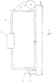
- a strapping device 1 is shown, which is provided with a control 2, a storage device 3 for storing and disposing of a strapping band, as well as with a strapping head 5.
- the strapping head 5 is used inter alia to generate a feed and to generate a return movement of the strapping. He is also provided with a tensioning device, for applying a belt tension on a belt loop, and a closure device for producing a closure on the strapping.
- the strapping device has a tape guide 6, with which the tape can be placed automatically and automatically on a predetermined path around a packaged goods 7.
- a welding and clamping unit 16 is integrated into the strapping head 5. Except for the strapping head 5, these are known components of strapping devices.
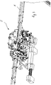
- the arranged together with the tape guide 6 on a frame 8 and in Fig. 2 separately shown strapping head 5 has a belt drive means 15.
- Belt drive devices are generally known, which is why below essentially addresses the differences to previously known belt drive devices.
- the tape drive device according to this embodiment can in particular with one or more pairs of rollers 11, 12; 13 and possibly be provided with further individual pulleys. The latter, however, do not participate in the generation of the band movement and are only intended for the determination of the band progression direction.
- the strapping head 5 has two components, a control component 16 and a band handling component 17.
- the control component 16 has, in addition to the execution of control functions for the components of the strapping device other functions, such as the generation of closures between the two band layers of a strapping as well as the separation of the strapping tape from the tape supply.
- the control component 16 is mounted on a sub-carrier 18 of the strapping head, wherein the sub-carrier 18 is in turn releasably secured to a common main carrier 19 of the strapping head 5.
- the sub-carrier 18 of the control component 16 is pivotable about an axis 23.
- the elements of the band handling component 17 are fastened directly to the main carrier 19 of the strapping head without its own partial carrier.
- the control component 16 is provided essentially for carrying out control and coordination functions of the functions performed with the strapping head.
- the tape handling component 17 and the components attached to it, on the other hand, are intended for direct action on the strapping band.
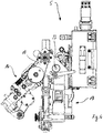
- a belt feed device 20 In the band handling component 17 of the strapping head 5, a belt feed device 20, a belt retraction device 21 and a tensioning device 22 are integrated.
- a belt feed device 20 In the band handling component 17 of the strapping head 5, a belt feed device 20, a belt retraction device 21 and a tensioning device 22 are integrated.
- the two rollers 11, 12 are driven by the same (only one) motor 14, in the embodiment an electric motor.
- a drive train to one of the two rollers 11, 12 may be performed.
- the role 11 is provided both as a drive wheel for the tape feed (Bandvorschubsrad) and as a drive wheel for the tape retraction (Bandrückzugsrad).
- the roller 11 with the same drive motor 14 can be driven in both directions of rotation.
- Fig. 6 is the direction of rotation counterclockwise, the tape feed direction and the direction of rotation in the clockwise direction Bandschreibzugides.
- the motor drive movement is transmitted to both wheels or rollers 11, 12 from the common motor 14 by means of a transmission device.
- the transmission device 14a comprises a toothed belt transmission which transmits the drive movement from the motor shaft to a further shaft running parallel to the motor shaft.
- two gears are arranged, each belonging to a further of two partial transmissions of the transmission device. From one of these two partial transmissions of the transmission device, the motor drive movement is transmitted to the roller or the wheel 11 and from the other partial transmission to the tensioning wheel 12.
- both the tensioning wheel 12 and the wheel 11 in different directions of rotation.
- the roller 11 is disposed above the roller 12.
- the roller 12 is part of the clamping device 22 and has the function of the tensioning wheel. It has a significantly larger diameter than the roller 11.
- the tensioning wheel 12 is due to the rigid connection with the motor 14 and the drive movements performed by the motor in both directions of rotation, also driven in both directions of rotation.
- the tensioning wheel only the drive movement is used in the clamping direction, ie based on the representation of Fig. 6 the direction of rotation in the clockwise direction.
- a subsequent to the clamping operation and the direction of rotation during the clamping process opposite rotational movement of the tensioning wheel take place a relaxation of the Umreifungskopf located and no longer belonging to the band loop band section.
- the drive movements both for the clamping movement and for the relaxation movement come from the same drive motor as for the roller 11.
- a switchable coupling provided with the drive movement either on the roller 11 or Roll 12 can be directed.
- the tensioning wheel can in turn be driven in both directions of rotation, it can also be provided that the tensioning wheel can also be driven only in the direction of rotation provided for the tensioning operation.
- roller 13 adjacent to both the roller 11 and the tensioning wheel 12.
- the roller 13 is rotationally driven and articulated pivotally by means of a pivoting device.
- the pivoting device is operatively connected to a drive, through which the roller can perform (motorized) driven pivoting movements.
- the pivoting movement acting as a counter-roller 13 can be brought either in abutment against the roller 11 or in abutment against the tensioning wheel 12, wherein in the respective end position of the pivotable roller 13, respectively, the strapping between one of the rollers 11, 12 and the roller 13 is located.
- the counter-roller 13 Depending on which of the rollers 11, 12, the counter-roller 13 is applied, the counter-roller 13 then pushes the tape to the corresponding roller 11, 12, so that the corresponding roller 11, 12 their rotation as possible slip-free as feed, retraction or tensioning movement as well as possibly transferred as a relaxation movement on the strapping.
- the counter-roller 13 is thus together with the roller 11 both part of the tape feed as well as part of the tape retracting device. Together with the tensioning wheel 12, the counter-roller 13 is also part of the tensioning device 22.
- the fourth roller which has hitherto been the case in previously known solutions, can be avoided.
- the drive roller and the tensioning wheel are each assigned one of two counter-rollers.
- the preferred 3-roll solution according to the invention can make a significantly more compact design possible.
- the rollers 11, 12, 13 are in Umreifungskopf 5 also part of a tape guide channel 28, through which the course and the forward and sudzugsweg of Bands is predetermined.
- the tape guide channel 28 is again part of the tape guide 6.
- the strapping head 5 on a first interface 29, at which the strapping head 5 connects to the supply roll side of the tape guide.
- the here formed one end of the band guide channel 28 is formed as a quick change interface. This has a by means of a pivotable clamping lever 30 to the strapping head clamped channel piece 31, through which the tape is fed into the strapping head.
- the channel piece 31 terminates immediately in front of the peripheral surface 11a of the roller 11, so that the strapping band can be fed at least approximately tangentially to the circumferential surface 11a of the roller 11. If the roller 13 is in its end position pivoted to the roller 11, then the belt is passed between the rollers 11, 13, the roller 13 pressing the belt against the roller 11.
- the band passes in its further course to the tensioning wheel 12.
- the counter-roller 13 formed by suitable channel forming means over about 180 ° on the circumference of the tensioning wheel 12 extending arcuate channel portion 28a.
- the channel section 28a is significantly wider than the strip thickness.
- the inner boundary of the channel section is formed by the section of the peripheral surface 12a of the tensioning wheel 12 located in the region of the channel section.
- the outer boundary of the channel section 28a in the radial direction has guide plates as well as an outer channel segment, which is pivotable together with the counter-roller 13, with which the outer channel section can be closed, although the pivotable counter-roller 13 is located in the area of the outer channel section. Without the pivotable channel segment 33 or an equivalent other element, at least one of the two pivot end positions of the counter-roller 13 would possibly result in an open position of the channel section, which could possibly have a negative effect with respect to a secure tape guide.
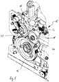
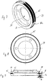
- the tensioning wheel is shown in three illustrations. This has a ring 37 which is provided with a recess 38 which is provided for connecting the tensioning wheel 12 with a shaft of the drive, in particular with a shaft of a transmission of the drive.
- Fig. 2 the tensioning wheel 12 mounted on the shaft is shown.
- Fig. 6 it is circular Tensioning wheel provided with a peripheral surface 12a with at least substantially constant width.
- the tensioning wheel 12 is provided on its circumferential surface 12a with a knurling or toothing 39, by which the engagement conditions of the tensioning wheel 12 are improved on the strapping.
- any other geometrically determined or indefinite roughening of the circumferential surface 12a of the tensioning wheel could be provided, with which a slippage between the tensioning wheel and the strapping band, which is possible during the tensioning process, can at least be largely prevented.
- a groove 40 is introduced at a distance from the lateral edges of the tensioning wheel over the entire circumference of the peripheral surface 12a with a comparatively small width, which is formed significantly deeper than wide.
- the groove 40 are in the embodiment, two rubber-elastic O-rings 43, 44 one above the other, which are arranged in the groove 40 radially one behind the other.
- one of the O-rings 43 is arranged with a smaller and the other O-rings 44 with a greater distance compared to the axis of rotation of the tensioning wheel 12.
- the width of the O-rings 43, 44 is provided such that they correspond approximately to the width of the groove 40.
- the two O-rings 43, 44 are completely within the groove 40. Both O-rings 43, 44 are formed of rubber-elastic material.
- a spacer ring 45 which is designed in the embodiment of a metallic material.
- the ring 45 is elastically deformable in this embodiment.
- the ring could be formed substantially rigid or dimensionally stable.
- the ring 45 could also be formed of one or more materials other than a metallic material, for example of an elastic plastic.
- this metal ring 45 is provided with respect to its cross section with a smaller width B than height H.
- the height of the O-ring is adjusted with respect to the groove depth and the height of the O-rings such that the ring with a height H 1 protrudes from the groove 40.
- the ring 45 is thus in his in Fig. 9 shown unloaded state on the peripheral surface 12a of the clamping ring 12 via, in particular over its entire circumference or over the entire circumference of the clamping ring 12.
- the strapping is pushed at the beginning of the strapping with preferably high speed of the strapping head 5 with its free end of the tape through the tape guide 6.
- the counter-roller 13 is in abutment against one side of the tape.
- the tape is pressed by the counter-roller with its other side against the motor-driven roller 11.
- the rotational drive movement of the roller 11 in the feed direction is thereby transmitted to the strapping, which causes its advancing movement in the feed direction.
- the tape comes behind the outlet region of the tape from the gap between the roller 11 and counter roller 13 in contact with the tensioning wheel 12, but without exerting on the tensioning wheel 12 a significant pressure.
- the control component 16 which is provided for this purpose with a basically known motor-driven camshaft control.
- Fig. 6 the tensioning wheel 12 is shown during the tape retraction process.
- the belt comes into abutment against the tensioning wheel 12 during the belt retraction process.
- the strapping belt lies essentially above the entire arcuate channel section 28a on the belt Tensioning wheel 12 on, similar to the case of the first subsequent clamping operation.
- the tape is withdrawn here, but due to its ability to yield to this movement by moving out of the tape guide as intended, only a comparatively small amount of tape tension is applied to the tape of the tape loop during this phase.
- the tape After the tape is applied to the packaged by the tape retraction, is switched by the control of tape retraction to generate a tape tension, so that the voltage applied to the packaged tape should be pulled tight.
- the counter-roller 13 is pivoted from its contact position against the roller 11 in an abutment position against the tensioning wheel 12.
- the tape On the other hand driven in the embodiment and faster rotating roller 11 is due to the lack of pressure of the counter-roller 13, the tape now, however, no longer in a manner by which the roller 11 could transmit their movement on the tape.
- the band is pulled back by the tensioning wheel 12 at most with a length that is short compared with the band retraction phase. During this tensioning phase, above all a greater tension is applied to the band.
- this thereby optionally deforms elastically and can again emerge from the groove along that peripheral portion, where the strapping band does not bear against the tensioning wheel, in part (with respect to its height).
- the ring 45 can protrude from the peripheral surface to a greater extent than in the unloaded state in which it projects beyond a height H 1 .
- the counter-roller 13 can be pressed with advantage with different pressure forces on the one hand against the roller 11 (feed roller or retraction roller) and on the other hand against the tensioning wheel 12 (in use of the strapping with each intermediate strapping). Compared to the possible Pressure forces against the roller 11 higher pressure forces against the tensioning wheel, can be for a high reliability and the ability to apply high band tensions on the strapping band advantage. The following therefore explains how in a preferred embodiment of the invention, despite the pivotal movement of the counter-roller 13 between two end positions in the end position different pressure forces can be realized.
- the counter-roller 13 is arranged on an eccentric 50, which in turn is arranged on a shaft 51 of a carrier 52.
- the carrier has at a distance from the shaft 52 a receptacle 53 which is provided for arrangement on the bearing 54 of the roller 11 ( Fig. 5 . 6 ).
- the receptacle 53 is in this case about its axis of rotation freely rotatable on the bearing 54 of the roller 11 and thus can perform pivotal movements about its axis of rotation.
- lever 57, 58, 59 In the area of the counter-roller 13 and the roller 11 is a more pivotally hinged together lever 57, 58, 59 exhibiting parallelogram provided.
- the parallelogram 56 has a long vertical lever 57, a horizontal lever 58 and a short vertical lever 59.
- the parallelogram is pivoted on the long vertical lever 57 and on the short vertical lever 59.
- the levers 57 and 59 have for this purpose pivot bearing points 60, 61. Via a bell curve 62, a rotary movement can be transmitted to the long vertical lever 57, which leads to the pivotal movement of the lever 57 about its pivot bearing point 60.
- the pivoting movement of the lever 57 takes place in a clockwise direction.
- the lever 58 thus pulls the latter at the pivot point of the short vertical lever in the direction of the lever 57, whereby the vertical lever 59 in the illustration of Fig. 11, 12th also pivots clockwise about its pivot bearing 62.
- An inclined surface 64 formed on the short vertical lever 59 thereby presses on a bearing 51 disposed on the shaft 51.
- the inclined surface thereby performs a clockwise movement (as shown in FIG Fig. 12 ) and has a tendency to take a horizontal orientation.
- the carrier 52 performs a pivoting movement, whereby the counter-roller 13 is pivoted from its end position against the roller 11 in the direction of the tensioning wheel 12.
- the counter-roller Upon reaching the tensioning wheel, the counter-roller bears against the tensioning wheel and can not perform any further pivoting movement. However, the lever 57 continues to pivot, whereby the bearing 65 of the eccentric 50 is moved counterclockwise in the direction of an L-shaped support 66. After the bearing 65 presses against the L-shaped support 65, stops the movement of the bearing 65 and this is at least approximately with an upper bearing 66, the axis of rotation 67 of the counter-roller 13 and the axis of rotation 68 of the tensioning wheel 12 in a line. A previously the pressure force of the counter-roller 13 generating spring element is thus no longer effective.
- a provision of the parallelogram can be done by a arranged on the pin 72 of the lever 5 further spring 73.
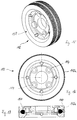
- a further preferred embodiment of a tensioning wheel 112 according to the invention is shown.
- the tensioning wheel 112 may be divided longitudinally with respect to its width, preferably approximately in the middle, wherein the two parts 112b, 112c of the tensioning wheel 112 are detachably connectable to one another by means of suitable fastening elements, for example screws 114.
- suitable fastening elements for example screws 114.
- a circumferential groove 140 is formed in the outer ring 137 of the tensioning wheel 112, which is open towards the peripheral surface 112a of the tensioning wheel 112 and is tapered or reduced in the direction towards it.
- one or more return elements may be arranged.
- resilient ring sections 143 for example a plurality of rubber-elastic O-ring sections 143, are arranged as the return element.
- these ring portions are spaced apart uniformly distributed in the groove 140, as in the embodiment with a total of four ring portions 143 of the case.
- the return elements 143 are located below one or more spacer elements.
- only a trained as a self-contained ring spacer 145 is provided.
- An outer diameter of the ring 145 arranged in the groove is dimensioned such that in the unloaded state of the ring 145 it protrudes with its outer circumferential surface over the peripheral surface 112a of the clamping ring 112.
- the ring 145 With its inner circumferential surface, the ring 145 is in the groove.
- the return elements are attached to the inner peripheral surface of the circular and substantially dimensionally stable ring 145. In other embodiments, a different number of spacers and a different number of return elements may be provided.
- the portion of the ring 145 protruding beyond the groove along this angular range can be pressed into the groove 140, so that in this fixed angular range of the tensioning wheel 112, the strapping band comes into abutment against the peripheral surface 112a of the tensioning wheel 112 and from the peripheral surface 112a the movement of the tensioning wheel 112 can be taken.
- the ring 145 can be pressed into the groove 140 in sections during the tensioning process, during which the strapping band exerts a sufficiently high compressive force on the ring 145 located in the strapping area of the strapping band.
- the compressive force on the portion of the ring 145 currently arranged in the looping area of the band is not sufficiently great to completely push this ring portion into the groove 140.
- the tape thereby rests against the portion of the ring 145 and not against the surface of the tensioning wheel 112.
- the ring 145 holds the strapping band at a distance from the peripheral surface of the tensioning wheel 112.
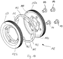
- FIG. 18 . 19 another embodiment of a belt drive device 115 is shown.
- This also has only three rollers 111, 112, 113, which are responsible for the application of the Bandvorschub-, Bandrückzugs- and the tape tension movement on the tape by contact with the belt, wherein the two rollers 111 and 112 by means of a motor, in particular by means of only a common engine, are drivable.
- the relative arrangement of Rotary axes of the three rollers 111, 112, 113 to each other at least approximately corresponds to the arrangement of these axes of rotation in the embodiment of Fig. 5 and 6 ,
- the counter-roller 113 is in turn pivotally formed so that it is provided in a pivot position for pressing the strapping against the roller 111 and in another pivot position for pressing the strapping against the tension roller 112.
- the purpose provided for this pivot mechanism of the counter-roller 113 and its drive can in principle the same manner as in the embodiment of Fig. 1 to 13 be educated.
- the counter-roller 113 is as in the embodiment of Fig. 5 and 6 rotatably supported on an eccentric 150, so that the counter-roller 113 performs a non-circular arc movement during a pivoting movement of one of the rollers 111, 112 to the other roller 111, 112.
- Fig. 5 and 6 rotatably supported on an eccentric 150
- a ventilation device 180 is mounted on the eccentric 150 of the counter-roller 113, wherein the ventilation device 180 is supported by a carrier 181 on the frame of the strapping device 101.
- the bearing point 182 of the ventilation device on the eccentric 150 is itself pivotally mounted on the eccentric and is designed as a C or fork-shaped element 183, thereby forming a receptacle for an end of a piston 184.
- This piston 184 is slidably disposed in the carrier 181 of the ventilation device 180.
- the support point is in the representation of Fig. 18 and 19 directly above the roller 111.
- the carrier 181 of the ventilation device is in this case also pivotally mounted.
- the ventilation device 180 is provided with a ventilating element, which is intended to carry out a controlled movement, with which the counter-roller 113 is acted on to ventilate the counter-roller 113 in its pivotal position on the roller 111 or slightly lift it off.
- the counter-roller 113 should be able to be employed again in its pivotal position in the roller 111 after a ventilation to the roller 111, for example also by means of the ventilation device.
- the ventilation element is designed as a solenoid 186, which is arranged and mounted on the ventilation device 180. The solenoid 186 can perform with its piston 184 a linear lifting movement along the longitudinal axis 184 a of its piston 184. As in Fig.
- the extended longitudinal axis 184a of the piston 184 in this case extends at least approximately through the articulation point of the C-shaped element 183.
- a stroke movement of the piston 184 in the direction of the counter-roller 113 thus leads to a rotational movement of the eccentric about its axis of rotation.
- the rotational movement takes place counterclockwise, as by comparing the two Fig. 18 and 19 can be determined.
- the rotational movement of the eccentric 150 causes the axis of rotation of the counter-roller 113 is moved in parallel and results in a gap or an enlarged gap between the roller 111 and the counter-roller 113.
- the width of the gap should in this case have a size which is greater than the thickness of the strapping band processed in each case.
- a solenoid for example, the product GKb-32.06 of the company Isliker Magnete AG, CH -8450 Andelfingen, are used.
- a mechanical spring element may be arranged, in particular at least one compression spring 188.
- This pressure spring 188 is compressed during the movement of the counter-roller 113 of the tension roller 112 for abutment against the roller 111 and thus stretched resiliently.
- the electrically actuated magnetic reciprocating piston is switched off in this phase and thus has no effect.
- the compression spring 188 is at least partially relaxed and the spring force acts in support of the force exerted by the solenoid, with which the piston 184 for the ventilation of the counter-roller 113 is moved by the roller 111.
- the solenoid or other return element alone provides a sufficiently high force for the ventilation process.
- the belt moves through the tape guide channel 28 in the feed direction.
- the tape strikes a stop or reaching the end of the tape guide channel can be detected in other ways, for example by a light barrier.
- a signal is generated by the control of the strapping device stops the motor drive movement of the roller 111 and - at least substantially simultaneously - triggers the lifting movement of the piston 184 of the solenoid.
- the stop of the drive movement of the roller 111 and the beginning of the ventilation process are offset in time with respect to each other, ie the stop of the drive movement takes place before or after the start of the ventilation process.
- the piston 184 extends in the direction of the C-shaped element 183 and acts with its end on the C or fork-shaped element. Due to its location on the eccentric 150 of the eccentric is rotated during the stroke of the piston.
- the rotational movement of the eccentric by a rotation angle of less than 90 ° takes place in the counterclockwise direction.
- the rotational movement takes place against the spring force of the pressure spring 190, which is thereby compressed and is also articulated on the eccentric 150.
- the counter-roller 113 is lifted from the roller 111, that is raised and the distance between the two rollers 111, 113 increased, so that a gap between the rollers is created, which is greater than the strip thickness.
- the strapping tape shot at high speed through the tape channel of the tape guide 6 has the tendency in generic strapping devices by the sudden and abrupt belt stop to form waves between the rollers 111, 112, 113 and the end of the strapping. In particular in the area of the rollers 111, 112, 113, such waves can lead to malfunctions.
- the belt in which the counter-roller 113 is released, the belt, in particular immediately after the stop of the feed can move as far as necessary and freely against the feed direction towards the supply of tape, so that possibly for the length of the band channel excess and the wave formation causing banding in the band guide channel can move back.
- the control of the strapping device can then turn off the solenoid again.
- the solenoid loses its effect, whereby the pressure spring 190, the eccentric 150 against the direction of rotation can move back again and thus brings the counter-roller 113 again in abutment position against the tape in which the tape between the roller 111 and the counter-roller 113 is clamped.
- the subsequent Bandlessnesszugs- and clamping operation can in the same manner as in the embodiments of the invention according to the Fig. 1 to 13 respectively.
Landscapes
- Engineering & Computer Science (AREA)
- Mechanical Engineering (AREA)
- Theoretical Computer Science (AREA)
- Physics & Mathematics (AREA)
- General Physics & Mathematics (AREA)
- Multimedia (AREA)
- Computer Hardware Design (AREA)
- General Engineering & Computer Science (AREA)
- General Health & Medical Sciences (AREA)
- Computational Linguistics (AREA)
- Audiology, Speech & Language Pathology (AREA)
- Artificial Intelligence (AREA)
- Health & Medical Sciences (AREA)
- Computer Vision & Pattern Recognition (AREA)
- Basic Packing Technique (AREA)
- User Interface Of Digital Computer (AREA)
Priority Applications (1)
| Application Number | Priority Date | Filing Date | Title |
|---|---|---|---|
| PL15711036T PL3105129T3 (pl) | 2014-02-10 | 2015-02-10 | Urządzenie opasujące |
Applications Claiming Priority (4)
| Application Number | Priority Date | Filing Date | Title |
|---|---|---|---|
| CH00181/14A CH709244A2 (de) | 2014-02-10 | 2014-02-10 | Spanneinrichtung einer Umreifungsvorrichtung zur Umreifung von Packgut mit einem Umreifungsband. |
| CH00183/14A CH709246A2 (de) | 2014-02-10 | 2014-02-10 | Umreifungseinrichtung einer Umreifungsvorrichtung zur Umreifung von Packgut mit einem Umreifungsband. |
| CH00182/14A CH709245A2 (de) | 2014-02-10 | 2014-02-10 | Umreifungseinrichtung einer Umreifungsvorrichtung zur Umreifung von Packgut mit einem Umreifungsband. |
| PCT/CH2015/000015 WO2015117256A1 (de) | 2014-02-10 | 2015-02-10 | Umreifungseinrichtung |
Publications (2)
| Publication Number | Publication Date |
|---|---|
| EP3105129A1 EP3105129A1 (de) | 2016-12-21 |
| EP3105129B1 true EP3105129B1 (de) | 2019-01-16 |
Family
ID=52697174
Family Applications (4)
| Application Number | Title | Priority Date | Filing Date |
|---|---|---|---|
| EP15711036.2A Active EP3105129B1 (de) | 2014-02-10 | 2015-02-10 | Umreifungseinrichtung |
| EP15711037.0A Active EP3105128B1 (de) | 2014-02-10 | 2015-02-10 | Umreifungseinrichtung mit einer bandvorschubeinrichtung |
| EP15711034.7A Active EP3105126B1 (de) | 2014-02-10 | 2015-02-10 | Spanneinrichtung für eine umreifungsvorrichtung |
| EP15711035.4A Active EP3105127B1 (de) | 2014-02-10 | 2015-02-10 | Umreifungseinrichtung |
Family Applications After (3)
| Application Number | Title | Priority Date | Filing Date |
|---|---|---|---|
| EP15711037.0A Active EP3105128B1 (de) | 2014-02-10 | 2015-02-10 | Umreifungseinrichtung mit einer bandvorschubeinrichtung |
| EP15711034.7A Active EP3105126B1 (de) | 2014-02-10 | 2015-02-10 | Spanneinrichtung für eine umreifungsvorrichtung |
| EP15711035.4A Active EP3105127B1 (de) | 2014-02-10 | 2015-02-10 | Umreifungseinrichtung |
Country Status (7)
| Country | Link |
|---|---|
| US (4) | US10220971B2 (pl) |
| EP (4) | EP3105129B1 (pl) |
| CH (4) | CH709221A2 (pl) |
| ES (1) | ES2883950T3 (pl) |
| PL (4) | PL3105129T3 (pl) |
| TR (1) | TR201905484T4 (pl) |
| WO (4) | WO2015117255A1 (pl) |
Families Citing this family (8)
| Publication number | Priority date | Publication date | Assignee | Title |
|---|---|---|---|---|
| PL3105129T3 (pl) | 2014-02-10 | 2019-07-31 | Orgapack Gmbh | Urządzenie opasujące |
| US10569914B2 (en) * | 2016-06-01 | 2020-02-25 | Signode Industrial Group Llc | Shock absorbing feed wheel assembly |
| IT201700005654A1 (it) * | 2017-01-19 | 2018-07-19 | Messersi Packaging Srl | Macchina reggiatrice con gruppo perfezionato di movimentazione della reggia |
| ES2870996T3 (es) * | 2018-04-19 | 2021-10-28 | Titan Umreifungstechnik Gmbh & Co Kg | Dispositivo de zunchado |
| MY207036A (en) | 2018-07-05 | 2025-01-26 | Philip Morris Products Sa | Inductively heated aerosol-generating system with ambient temperature sensor |
| EP3960642B1 (en) * | 2020-08-28 | 2024-04-17 | Signode Finland Oy | Automatic-strap-feeding system for feeding strap into a strapping machine |
| US12240645B2 (en) | 2020-11-17 | 2025-03-04 | Signode Industrial Group Llc | Strap-feeding assembly with strap-size-adjustment features |
| CA3205609A1 (en) * | 2020-12-23 | 2022-06-30 | Signode Industrial Group Llc | Strap-tensioning assembly with self-energizing tensioning wheel and strap-size-adjustment features |
Family Cites Families (189)
| Publication number | Priority date | Publication date | Assignee | Title |
|---|---|---|---|---|
| US2194108A (en) | 1935-11-30 | 1940-03-19 | Acme Steel Co | Box strapping machine |
| US2707429A (en) | 1948-09-09 | 1955-05-03 | Signode Steel Strapping Co | Automatic strapping machine |
| US3120171A (en) | 1958-01-28 | 1964-02-04 | Acme Steel Co | Automatic strapping machine |
| US3232217A (en) | 1964-05-04 | 1966-02-01 | Stanley Works | Strapping machine |
| US3367374A (en) | 1965-04-08 | 1968-02-06 | Signode Corp | Gripper plug |
| FR1513685A (fr) | 1966-02-02 | 1968-02-16 | Signode Corp | Appareil perfectionné pour cercler des objets au moyen de bandes de cerclage en matière thermoplastique |
| GB1161827A (en) | 1966-11-29 | 1969-08-20 | Naigai Seikosho Kk | Band Feeding and Tightening Device of Automatic Strapping Machines. |
| US3526187A (en) * | 1968-10-02 | 1970-09-01 | Signode Corp | Toggle controlled strapping apparatus and method |
| US3566778A (en) * | 1969-01-27 | 1971-03-02 | Signode Corp | Strap feeding and tensioning system |
| US3654033A (en) | 1970-04-01 | 1972-04-04 | Signode Corp | Strap tensioning and sealing tool |
| JPS5423999Y2 (pl) | 1975-12-27 | 1979-08-15 | ||
| US4011807A (en) | 1976-01-21 | 1977-03-15 | Signode Corporation | Strap feeding and tensioning machine |
| US4050372A (en) | 1976-01-21 | 1977-09-27 | Signode Corporation | Automatic strapping machine |
| US4015643A (en) | 1976-01-21 | 1977-04-05 | Signode Corporation | Tensioning tool with self-energizing gripper plug |
| JPS5379695A (en) | 1976-12-22 | 1978-07-14 | Naigai Steel Works | Packing machine |
| US4120239A (en) * | 1977-03-10 | 1978-10-17 | Ovalstrapping, Inc. | Strapping machine |
| JPS5953143B2 (ja) | 1977-06-07 | 1984-12-24 | 旭化成株式会社 | 連続鋳造用鋳型 |
| JPS5839790B2 (ja) | 1977-06-21 | 1983-09-01 | 川崎重工業株式会社 | セメントクリンカの焼成装置 |
| DE2858372C2 (pl) * | 1978-04-26 | 1991-10-24 | Ovalstrapping, Inc., Hoquiam, Wash., Us | |
| GB2041869B (en) | 1979-02-23 | 1982-12-08 | Nichiro Kogyo Kk | Band feeding and tightening method and device for strapping machinqe |
| US4240865A (en) | 1979-06-25 | 1980-12-23 | Interlake, Inc. | Apparatus and method for applying plastic strap |
| US4313779A (en) | 1979-07-30 | 1982-02-02 | Signode Corporation | All electric friction fusion strapping tool |
| ZA804443B (en) | 1979-07-30 | 1981-07-29 | Signode Corp | All electric friction fusion strapping tool |
| US4535730A (en) | 1980-12-08 | 1985-08-20 | Allen Dillis V | Rocker engine |
| IT1135722B (it) | 1981-03-24 | 1986-08-27 | Mec Sestese S A S Di Rossi Cri | Dispositivo di avanzamento e tensionamento della reggia in macchine reggiatrici |
| DE3118710A1 (de) | 1981-05-12 | 1982-12-09 | Cyklop International Emil Hoffmann KG, 5000 Köln | Vorrichtung zum spannen, verschliessen und abschneiden von kunststoffbaendern fuer packstueckumreifungen |
| DE3220446A1 (de) * | 1982-05-29 | 1984-01-26 | Hoesch Werke Ag, 4600 Dortmund | Vorschub- und spannvorrichtung fuer ein um ein packstueck zu spannendes umreifungsband |
| KR880002177B1 (ko) | 1982-11-15 | 1988-10-17 | 마쓰소노 히사미 | 산성유(乳) 음료의 제조법 |
| US4502911A (en) | 1983-07-27 | 1985-03-05 | Cyklop International Emil Hoffman, Kg | Strapping machine |
| US4572064A (en) | 1984-05-23 | 1986-02-25 | Burton R Edward | Brush bundling system |
| CH665604A5 (de) | 1985-01-23 | 1988-05-31 | Strapex Ag | Spann- und verschliessgeraet fuer kunststoffband. |
| CH668402A5 (de) * | 1985-03-15 | 1988-12-30 | Konrad Feinmechanik Ag A | Verfahren und maschine zur umreifung eines packgutes mit einem umreifungsband. |
| US4724659A (en) | 1985-12-24 | 1988-02-16 | Nichiro Kogyo Company Ltd. | Band type strapping machine |
| US4776905A (en) | 1986-06-06 | 1988-10-11 | Signode Corporation | Method and apparatus for producing a welded joint in thermoplastic strap |
| US4707390A (en) | 1986-06-06 | 1987-11-17 | Signode Corporation | Thermoplastic strap weld with encapsulated cavities |
| US4912912A (en) | 1987-05-30 | 1990-04-03 | Strapack Corporation | Control apparatus in strapping machine |
| JP2647685B2 (ja) | 1988-04-15 | 1997-08-27 | シグノード株式会社 | 結束ストラップの操作装置 |
| JPH0649485B2 (ja) | 1988-04-15 | 1994-06-29 | シグノード株式会社 | 結束ストラップの送出し、引戻し、引締め操作装置 |
| GB8812292D0 (en) | 1988-05-24 | 1988-06-29 | Black & Decker Inc | Improvements in/relating to power tools |
| RU1772784C (ru) | 1989-11-04 | 1992-10-30 | Опытное Конструкторско-Технологическое Бюро С Опытным Производством Института Металлофизики Ан Усср | Устройство дл автоматического управлени приводом |
| JP2740804B2 (ja) | 1990-02-09 | 1998-04-15 | ストラパック株式会社 | 梱包機における空梱包バンドの除去方法 |
| US5628348A (en) | 1990-04-02 | 1997-05-13 | Edge Technology Corporation | Tensioning apparatus |
| DE4014305C2 (de) * | 1990-05-04 | 1996-07-18 | Rmo Systempack Gmbh | Vorrichtung zum Verbinden von sich überlappenden Abschnitten eines thermoplastischen Bandes |
| DE4014307C2 (de) | 1990-05-04 | 1996-11-07 | Rmo Systempack Gmbh | Packmaschine |
| US5133532A (en) | 1990-10-11 | 1992-07-28 | Illinois Tool Works Inc. | Method and apparatus for controlling tension in a strap loop |
| US5146847A (en) | 1991-04-01 | 1992-09-15 | General Motors Corporation | Variable speed feed control and tensioning of a bander |
| US5165532A (en) | 1991-05-29 | 1992-11-24 | Westinghouse Electric Corp. | Circuit breaker with interlock for welding contacts |
| US5159218A (en) | 1991-07-09 | 1992-10-27 | Allied-Signal Inc. | Motor with integral controller |
| JPH0747284Y2 (ja) | 1991-10-01 | 1995-11-01 | 昌弘機工株式会社 | 自動梱包機 |
| JP2857280B2 (ja) | 1992-06-10 | 1999-02-17 | ストラパック株式会社 | 梱包機におけるバンド供給・引締方法及び装置 |
| JP3044132B2 (ja) | 1992-07-20 | 2000-05-22 | ストラパック株式会社 | 梱包機におけるバンド接着方法及びその装置 |
| IT1256240B (it) | 1992-12-23 | 1995-11-29 | Sestese Off Mec | Dispositivo di controllo del trascinamento della reggia in una macchina reggiatrice |
| GB9320181D0 (en) | 1993-09-30 | 1993-11-17 | Black & Decker Inc | Improvements in and relating to power tools |
| DE9316072U1 (de) | 1993-10-21 | 1994-01-05 | Cyklop GmbH, 50996 Köln | Vorrichtung zum Spannen und Verschließen von Umreifungsbändern |
| US5377477A (en) * | 1993-12-09 | 1995-01-03 | Signode Corporation | Method and apparatus for a power strapping machine |
| JPH07187119A (ja) | 1993-12-28 | 1995-07-25 | Kioritz Corp | 梱包機 |
| US5516022A (en) | 1994-02-28 | 1996-05-14 | Illinois Tool Works, Inc. | Method and apparatus for a two speed strap take up |
| JPH07300108A (ja) | 1994-05-09 | 1995-11-14 | Kioritz Corp | 梱包機 |
| DE69530587T2 (de) | 1994-06-24 | 2004-03-25 | Talon Industries, LLC, Vail | Kabelbindewerkzeug mit antriebsmechanismus |
| TW291470B (pl) | 1995-02-14 | 1996-11-21 | Nichiro Kogyo Kk | |
| JPH08258808A (ja) | 1995-03-24 | 1996-10-08 | Kioritz Corp | 梱包機 |
| CA2176636A1 (en) | 1995-05-26 | 1996-11-27 | Nikolaus Stamm | Tensioning and sealing apparatus for strapping an object with a band |
| ATE195476T1 (de) | 1995-05-26 | 2000-09-15 | Orgapack Gmbh | Spann- und verschliessvorrichtung zum umreifen eines gegenstandes mit einem kunststoffband |
| JP3044132U (ja) | 1995-09-09 | 1997-12-16 | 憲三郎 竹内 | とうふで造ったかりんとう |
| US5778643A (en) * | 1996-03-14 | 1998-07-14 | Officina Meccanica Sestese S.P.A. | Device to control the feeding of the strap in a strapping machine |
| JP3286524B2 (ja) | 1996-04-15 | 2002-05-27 | 三洋電機株式会社 | バッテリパック |
| US5798596A (en) | 1996-07-03 | 1998-08-25 | Pacific Scientific Company | Permanent magnet motor with enhanced inductance |
| JP3227693B2 (ja) | 1996-08-02 | 2001-11-12 | マックス株式会社 | 鉄筋結束機におけるワイヤのねじ切れ防止方法 |
| CN2266566Y (zh) | 1996-09-14 | 1997-11-05 | 泛源股份有限公司 | 手提式捆绑机 |
| US5809873A (en) | 1996-11-18 | 1998-09-22 | Ovalstrapping, Inc. | Strapping machine having primary and secondary tensioning units and a control system therefor |
| RU2161773C2 (ru) | 1996-12-14 | 2001-01-10 | Владимир Федотович Русинов | Устройство для определения угла |
| DE19751861A1 (de) | 1997-06-26 | 1999-01-07 | Dieter Bohlig | Elektrische Antriebseinrichtung zur Steuerung von Bewegungsvorgängen |
| US5853524A (en) | 1997-06-26 | 1998-12-29 | Illinois Tool Works Inc. | Pneumatic circuit for strapping tool having adjustable tension control |
| DE19730449A1 (de) | 1997-07-16 | 1999-01-21 | Mosca G Maschf | Spannvorrichtung für Umreifungsmaschinen |
| US5954899A (en) | 1998-04-03 | 1999-09-21 | Illinois Tool Works Inc. | Strap welding tool with base plate for reducing strap column strength and method therefor |
| US6003578A (en) | 1998-05-04 | 1999-12-21 | Chang; Jeff Chieh Huang | Portable electrical wrapping apparatus |
| ATE252018T1 (de) | 1998-10-29 | 2003-11-15 | Orgapack Gmbh | Umreifungsgerät |
| EP0997377B1 (de) | 1998-10-29 | 2003-09-17 | Orgapack GmbH | Umreifungsgerät |
| DE59905049D1 (de) | 1998-10-29 | 2003-05-22 | Orgapack Gmbh Dietikon | Umreifungsgerät |
| JP3242081B2 (ja) | 1998-12-11 | 2001-12-25 | 鋼鈑工業株式会社 | ストラップ引締溶着工具 |
| US6109325A (en) | 1999-01-12 | 2000-08-29 | Chang; Jeff Chieh Huang | Portable electrical binding apparatus |
| US6073664A (en) | 1999-02-13 | 2000-06-13 | Illinois Tool Works Inc. | Strap tensioning tool |
| DE19909620A1 (de) | 1999-03-05 | 2000-09-07 | Cyklop Gmbh | Vorrichtung zum Spannen und Verschließen von Umreifungsbändern |
| DE29904910U1 (de) | 1999-03-17 | 1999-06-10 | Tekpak Corp., Taichung | Führungsband-Verpackungsmaschine |
| US6079457A (en) | 1999-04-09 | 2000-06-27 | Illinois Tool Works Inc. | Sealless strapping tool and method therefor |
| US6711883B2 (en) | 1999-05-05 | 2004-03-30 | Smb Schwede Maschinenbau Gmbh | Strapping machine for strapping a stack of products |
| DE19937828C1 (de) | 1999-08-11 | 2000-10-05 | Smb Schwede Maschinenbau Gmbh | Schweißkopf für eine Bandumreifungsmaschine |
| IT1313685B1 (it) | 1999-11-25 | 2002-09-09 | Macpro S A S Di Alberto Galli | Testa reggiatrice per macchina da imballaggio. |
| US6415712B1 (en) | 1999-12-02 | 2002-07-09 | Enterprises International, Inc. | Track mechansim for guiding flexible straps around bundles of objects |
| US6584891B1 (en) | 2000-03-15 | 2003-07-01 | Enterprises International, Inc. | Apparatus and methods for wire-tying bundles of objects |
| US6463848B1 (en) | 2000-05-08 | 2002-10-15 | Illinois Tool Works Inc. | Strapper with improved winding and cutting assembly |
| DE10026200A1 (de) | 2000-05-26 | 2001-11-29 | Cyklop Gmbh | Vorrichtung zum Spannen von Umreifungsbändern |
| DE10026198A1 (de) | 2000-05-26 | 2001-11-29 | Cyklop Gmbh | Vorrichtung zum Spannen und Verschließen von Kunststoff-Umreifungsbändern |
| US6533013B1 (en) | 2000-06-02 | 2003-03-18 | Illinois Tool Works Inc. | Electric strapping tool and method therefor |
| WO2001094206A1 (en) | 2000-06-06 | 2001-12-13 | Kim Michael Jensen | A method and an apparatus for twisting and tightening a wire |
| US6367732B1 (en) | 2000-06-19 | 2002-04-09 | Illinois Tool Works Inc. | Strapping machine with twisted belt drive |
| JP2002080010A (ja) | 2000-06-28 | 2002-03-19 | Strapack Corp | 梱包機 |
| US6568158B2 (en) | 2000-07-31 | 2003-05-27 | Strapack Corporation | Band-applying apparatus and method for use in packing system |
| US6405766B1 (en) | 2000-11-29 | 2002-06-18 | Eaton Corporation | Noise dampened float type fuel vapor vent valve |
| DE10065356C1 (de) | 2000-12-27 | 2002-09-12 | Gkn Automotive Gmbh | Elektromechanische Drehmomentregelung - Beschleunigung des Rücklaufs |
| US20020134811A1 (en) | 2001-01-29 | 2002-09-26 | Senco Products, Inc. | Multi-mode power tool utilizing attachment |
| JP3699048B2 (ja) | 2001-02-01 | 2005-09-28 | ハン イル エ ワ カンパニーリミテッド | 物品装着用クリップ |
| ES2211839T3 (es) | 2001-03-22 | 2004-07-16 | Maschinenfabrik Gerd Mosca Ag | Maquina de zunchado con marco de conduccion de fleje divisible. |
| NZ519012A (en) | 2001-05-21 | 2003-10-31 | Orgapack Gmbh | Manually actuated strapping unit for wrapping a steel strap around a packaged item |
| US6629398B2 (en) | 2001-07-12 | 2003-10-07 | Illinois Tool Works, Inc. | Strapping machine with improved refeed |
| US6543341B2 (en) | 2001-07-12 | 2003-04-08 | Illinois Tool Works, Inc. | Strapping machine with strapping head sensor |
| CN2486463Y (zh) | 2001-07-27 | 2002-04-17 | 华展包装机械(昆山)有限公司 | 一种捆包机的控制电路 |
| US6463721B1 (en) | 2001-07-27 | 2002-10-15 | Su Chi-Jan | Strapping machine with a strap tightening unit |
| US6633798B2 (en) | 2001-07-31 | 2003-10-14 | L & P Property Management Company | Control system for baling machine |
| JP2003170906A (ja) | 2001-09-28 | 2003-06-17 | Strapack Corp | 梱包方法および梱包機 |
| WO2003033307A1 (es) | 2001-10-15 | 2003-04-24 | Grupo Antolin-Ingenieria, S.A. | Sistema de fijación de accesorios para el interior de vehículos |
| US6877420B2 (en) | 2003-05-28 | 2005-04-12 | Illinois Tool Works, Inc. | Strapping machine with retained program timers for safety interlocks and method |
| JP2003231291A (ja) | 2002-02-07 | 2003-08-19 | Fujitsu Component Ltd | サーマルプリンタ |
| JP2003246304A (ja) | 2002-02-26 | 2003-09-02 | Nichiro Kogyo Co Ltd | 梱包用バンドの操作シール装置 |
| DE10218135B4 (de) | 2002-04-23 | 2006-07-27 | Titan Umreifungstechnik Gmbh & Co Kg | Vorrichtung zum Umreifen von Warenstücken mit Band |
| JP4345260B2 (ja) | 2002-05-20 | 2009-10-14 | パナソニック株式会社 | 付加機能付電動工具 |
| JP2003348899A (ja) | 2002-05-27 | 2003-12-05 | Matsushita Electric Ind Co Ltd | モ−タの制御方法及び制御装置 |
| US6907717B2 (en) | 2002-06-14 | 2005-06-21 | Illinois Tool Works, Inc. | Dual motor strapper |
| US7312609B2 (en) | 2002-07-26 | 2007-12-25 | Robert Bosch Gmbh | GMR sensor element and its use |
| ES2283737T3 (es) | 2002-10-25 | 2007-11-01 | Orgapack Gmbh | Conjunto flejador. |
| US7121194B2 (en) | 2002-11-27 | 2006-10-17 | Illinois Tool Works, Inc. | Strapping machine having improved winder assembly |
| GB2396596B (en) | 2002-12-23 | 2005-12-07 | Tekpak Corp | Deadlocked strap releasing device for a strapping machine |
| US6732638B1 (en) | 2003-01-15 | 2004-05-11 | Illinois Tool Works, Inc. | Time-out indicator for pneumatic strapper |
| US7082872B2 (en) | 2003-01-21 | 2006-08-01 | Eam-Mosca Corporation | Strap tensioning apparatus |
| JP2004241150A (ja) | 2003-02-03 | 2004-08-26 | Yuasa Corp | 電池 |
| US6911799B2 (en) | 2003-04-25 | 2005-06-28 | Illinois Tool Works, Inc. | Strapping machine weld motor control system |
| US6789469B1 (en) | 2003-04-29 | 2004-09-14 | Illinois Tool Works, Inc. | Bundling assembly for strapping machine |
| US6837156B2 (en) | 2003-06-04 | 2005-01-04 | Ben Clements & Sons, Inc. | Twist tie feed device |
| US6955119B2 (en) | 2003-06-17 | 2005-10-18 | Illinois Tool Works, Inc. | Strapping machine with pivotal work surfaces having integral conveyors |
| US6820402B1 (en) | 2003-06-20 | 2004-11-23 | Illinois Tool Works, Inc. | Strapping machine with pivoting dispenser loading |
| US6857252B2 (en) | 2003-06-20 | 2005-02-22 | Illinois Tool Works, Inc. | Strapping machine with strap path access guide |
| DE20321137U1 (de) | 2003-09-29 | 2006-01-12 | Robert Bosch Gmbh | Akkuschrauber |
| DE10345135A1 (de) | 2003-09-29 | 2005-04-21 | Bosch Gmbh Robert | Akkuschrauber |
| JP2004108593A (ja) | 2003-12-18 | 2004-04-08 | Osaka Kakuta Kogyo Kk | トグルクランプ |
| FR2864762B1 (fr) | 2004-01-06 | 2007-06-01 | Seb Sa | Appareil electromenager de preparation d'aliments prevu pour etre mis en veille et pour etre reactive |
| EP1564146B1 (en) | 2004-02-13 | 2007-07-25 | Thomas & Betts International, Inc. | Cycle counter for cable tie tool |
| JP2006000993A (ja) | 2004-06-21 | 2006-01-05 | Maeda Metal Industries Ltd | 反力受け付き締付機 |
| TWM266243U (en) | 2004-07-20 | 2005-06-01 | Tekpak Corp | Baling machine capable of automatically adjusting the tension of band |
| US6994019B1 (en) | 2004-10-25 | 2006-02-07 | Tepak Corporation | Expand-and-constrict style band guiding device for a strapping machine |
| TWI322783B (en) | 2004-11-04 | 2010-04-01 | Orgapack Gmbh | A friction welding equipment for a packaging machine |
| US20060108180A1 (en) | 2004-11-24 | 2006-05-25 | Lincoln Industrial Corporation | Grease gun |
| US7073431B1 (en) | 2005-05-18 | 2006-07-11 | Yu-Fu Chen | Structure portable strapping machine |
| DE102005049130A1 (de) | 2005-10-14 | 2007-04-19 | Robert Bosch Gmbh | Handwerkzeugmaschine |
| US7270054B2 (en) | 2006-01-18 | 2007-09-18 | Illinois Tool Works, Inc. | Integrated package pacer for strapping machine |
| DE102006007990A1 (de) | 2006-02-21 | 2007-08-30 | Robert Bosch Gmbh | Handwerkzeugmaschine |
| KR200419048Y1 (ko) | 2006-03-17 | 2006-06-16 | 엘에스산전 주식회사 | 배선용 차단기 |
| JP4961808B2 (ja) | 2006-04-05 | 2012-06-27 | マックス株式会社 | 鉄筋結束機 |
| US7240612B1 (en) | 2006-05-03 | 2007-07-10 | Illinois Tool Works Inc. | Strapping machine |
| JP2008055563A (ja) | 2006-08-31 | 2008-03-13 | Matsushita Electric Works Ltd | 電動工具 |
| US7454877B2 (en) | 2006-09-26 | 2008-11-25 | Illinois Tool Works Inc. | Tension control system and method for tensioning a strapping material around a load in a strapping machine |
| US7263928B1 (en) | 2006-10-30 | 2007-09-04 | Illinois Tool Works, Inc. | Automatic chute opening system for strapping machine |
| US7270055B1 (en) | 2006-11-10 | 2007-09-18 | Illnois Tool Works, Inc. | Centrifugal boost wheel for strapping machine |
| US7497068B2 (en) | 2007-07-10 | 2009-03-03 | Illinois Tool Works Inc. | Two-piece strapping tool |
| US7377213B1 (en) * | 2007-09-07 | 2008-05-27 | Illinois Tool Works Inc. | Strapping machine with improved tension, seal and feed arrangement |
| CN101164416B (zh) | 2007-10-15 | 2010-06-02 | 嘉兴市威尔美尼机械制造有限公司 | 高速线扎机 |
| US8356641B2 (en) | 2007-11-02 | 2013-01-22 | Band-It-Idex, Inc. | Stationary band clamping apparatus |
| RU2355821C1 (ru) | 2008-04-11 | 2009-05-20 | Закрытое акционерное общество Фирма "Автоконинвест" | Состав для защиты металлов от коррозии и солеотложений |
| ES2539151T3 (es) | 2008-04-23 | 2015-06-26 | Premark Packaging Llc | Dispositivo de flejado con un dispositivo tensor |
| CN105173166B (zh) | 2008-04-23 | 2019-01-04 | 信诺国际Ip控股有限责任公司 | 移动式捆扎设备 |
| ES2387345T3 (es) | 2008-04-23 | 2012-09-20 | Orgapack Gmbh | Dispositivo de zunchado con un mecanismo de engranaje |
| CN201411059Y (zh) | 2008-04-23 | 2010-02-24 | 奥格派克有限公司 | 带有储能器的捆扎设备 |
| EP4438503A3 (de) | 2008-04-23 | 2025-09-03 | Signode International IP Holdings LLC | Umreifungsvorrichtung mit einem elektrischen antrieb |
| US7861649B2 (en) | 2008-12-19 | 2011-01-04 | Illinois Tool Works Inc. | Self-adjusting stripper pin for strapping machine strap chute |
| CN101486329B (zh) | 2009-02-13 | 2012-02-22 | 浙江双友物流器械股份有限公司 | 捆绑器 |
| CN101585244A (zh) | 2009-03-25 | 2009-11-25 | 张瑞东 | 一种双电机电动打包机 |
| ATE530449T1 (de) | 2009-04-24 | 2011-11-15 | Sund Birsta Ab | Umreifungseinheit und verfahren |
| DE102009047443B4 (de) | 2009-12-03 | 2024-04-11 | Robert Bosch Gmbh | Handwerkzeugmaschine |
| DE102009055313B4 (de) | 2009-12-23 | 2011-09-22 | Smb Schwede Maschinenbau Gmbh | Bandantriebseinrichtung für eine Umreifungsmaschine |
| ES2851174T3 (es) | 2010-04-16 | 2021-09-03 | Ue Systems Inc | Espectro de frecuencias ultrasónicas integrado y generación de imágenes |
| US9296501B2 (en) | 2010-07-22 | 2016-03-29 | Signode Industrial Group Llc | Modular strap feeder with motor for indexing and gripping |
| US8967217B2 (en) | 2011-02-22 | 2015-03-03 | Signode Industrial Group Llc | Hand-held strapper |
| US8522678B2 (en) | 2011-02-24 | 2013-09-03 | Tekpak Corporation | Strapping machine having a movable working assembly |
| DE102011075629B4 (de) | 2011-05-11 | 2016-09-15 | Smb Schwede Maschinenbau Gmbh | Verfahren zur Ansteuerung der Bandantriebseinrichtung einer Umreifungsmaschine sowie entsprechende Umreifungsmaschine |
| CN202100012U (zh) | 2011-05-30 | 2012-01-04 | 袁炽坤 | 多功能钢筋绑扎机 |
| GB2481725B (en) | 2011-07-13 | 2012-10-03 | Chien-Fa Lai | Reverse tension mechanism for a strapping machine |
| GB2481724B (en) | 2011-07-13 | 2012-10-03 | Chien-Fa Lai | Feeding and reversing mechanism for a strapping machine |
| DE202011050797U1 (de) | 2011-07-22 | 2011-11-11 | Pantech International Inc. | Kipphebelanordnung einer Umreifungsmaschine |
| US8683919B2 (en) | 2011-09-15 | 2014-04-01 | Illinois Tool Works Inc. | Modular strap feed head with forming wheels |
| US8689684B2 (en) | 2011-10-19 | 2014-04-08 | Illinois Tool Works Inc. | Automatic strap loading assembly for strapping machine |
| CH705744A2 (de) * | 2011-11-14 | 2013-05-15 | Illinois Tool Works | Umreifungsvorrichtung. |
| CH705745A2 (de) | 2011-11-14 | 2013-05-15 | Illinois Tool Works | Umreifungsvorrichtung. |
| CH705743A2 (de) | 2011-11-14 | 2013-05-15 | Illinois Tool Works | Umreifungsvorrichtung. |
| US9745090B2 (en) | 2012-04-24 | 2017-08-29 | Signode Industrial Group Llc | Modular strapping machine for steel strap |
| US8701555B2 (en) * | 2012-04-25 | 2014-04-22 | Illinois Tool Works Inc. | Tension head for modular steel strapping machine |
| US8720326B2 (en) | 2012-04-25 | 2014-05-13 | Illinois Tool Works Inc. | Sealing head for modular steel strapping machine |
| ES2895662T3 (es) | 2012-09-24 | 2022-02-22 | Signode Int Ip Holdings Llc | Dispositivo de flejado con un balancín pivotante |
| CH708294A2 (de) | 2013-05-05 | 2014-12-15 | Orgapack Gmbh | Umreifungsvorrichtung. |
| US20190046819A2 (en) | 2014-01-23 | 2019-02-14 | Signode Industrial Group Llc | Strapping device having a strip feed device |
| PL3105129T3 (pl) | 2014-02-10 | 2019-07-31 | Orgapack Gmbh | Urządzenie opasujące |
-
2015
- 2015-02-10 PL PL15711036T patent/PL3105129T3/pl unknown
- 2015-02-10 US US15/117,416 patent/US10220971B2/en active Active
- 2015-02-10 PL PL15711034T patent/PL3105126T3/pl unknown
- 2015-02-10 CH CH00171/15A patent/CH709221A2/de unknown
- 2015-02-10 WO PCT/CH2015/000014 patent/WO2015117255A1/de not_active Ceased
- 2015-02-10 WO PCT/CH2015/000013 patent/WO2015117254A1/de not_active Ceased
- 2015-02-10 CH CH00168/15A patent/CH709218A2/de not_active Application Discontinuation
- 2015-02-10 US US15/117,410 patent/US10513358B2/en active Active
- 2015-02-10 WO PCT/CH2015/000016 patent/WO2015117257A1/de not_active Ceased
- 2015-02-10 ES ES15711037T patent/ES2883950T3/es active Active
- 2015-02-10 CH CH00170/15A patent/CH709220A2/de not_active Application Discontinuation
- 2015-02-10 US US15/117,403 patent/US10689140B2/en active Active
- 2015-02-10 EP EP15711036.2A patent/EP3105129B1/de active Active
- 2015-02-10 PL PL15711035T patent/PL3105127T3/pl unknown
- 2015-02-10 EP EP15711037.0A patent/EP3105128B1/de active Active
- 2015-02-10 WO PCT/CH2015/000015 patent/WO2015117256A1/de not_active Ceased
- 2015-02-10 EP EP15711034.7A patent/EP3105126B1/de active Active
- 2015-02-10 CH CH00169/15A patent/CH709219A2/de not_active Application Discontinuation
- 2015-02-10 EP EP15711035.4A patent/EP3105127B1/de active Active
- 2015-02-10 PL PL15711037T patent/PL3105128T3/pl unknown
- 2015-02-10 TR TR2019/05484T patent/TR201905484T4/tr unknown
-
2020
- 2020-05-14 US US15/931,698 patent/US11312519B2/en active Active
Non-Patent Citations (1)
| Title |
|---|
| None * |
Also Published As
| Publication number | Publication date |
|---|---|
| WO2015117255A1 (de) | 2015-08-13 |
| PL3105126T3 (pl) | 2018-11-30 |
| EP3105127B1 (de) | 2019-06-05 |
| US10689140B2 (en) | 2020-06-23 |
| TR201905484T4 (tr) | 2019-05-21 |
| EP3105126A1 (de) | 2016-12-21 |
| WO2015117254A1 (de) | 2015-08-13 |
| US20170015450A1 (en) | 2017-01-19 |
| PL3105128T3 (pl) | 2021-11-22 |
| US20190050663A2 (en) | 2019-02-14 |
| US20160350613A1 (en) | 2016-12-01 |
| PL3105127T3 (pl) | 2019-11-29 |
| EP3105126B1 (de) | 2018-07-11 |
| ES2883950T3 (es) | 2021-12-09 |
| EP3105129A1 (de) | 2016-12-21 |
| US20200270007A1 (en) | 2020-08-27 |
| US11312519B2 (en) | 2022-04-26 |
| CH709221A2 (de) | 2015-08-14 |
| US20170015451A1 (en) | 2017-01-19 |
| CH709219A2 (de) | 2015-08-14 |
| WO2015117257A1 (de) | 2015-08-13 |
| PL3105129T3 (pl) | 2019-07-31 |
| EP3105128B1 (de) | 2021-04-28 |
| CH709220A2 (de) | 2015-08-14 |
| EP3105127A1 (de) | 2016-12-21 |
| EP3105128A1 (de) | 2016-12-21 |
| US10220971B2 (en) | 2019-03-05 |
| CH709218A2 (de) | 2015-08-14 |
| US10513358B2 (en) | 2019-12-24 |
| WO2015117256A1 (de) | 2015-08-13 |
Similar Documents
| Publication | Publication Date | Title |
|---|---|---|
| EP3105129B1 (de) | Umreifungseinrichtung | |
| DE69713440T2 (de) | Vorrichtung zum Umhüllen eines Gegenstandes mit einer Folie | |
| DE2352157C3 (de) | Bindevorrichtung zum Umbinden von Bündeln mit Bindedraht | |
| DE1561728B2 (de) | Bogenfoerdervorrichtung | |
| DE19547282B4 (de) | Pakettiermaschine | |
| EP3812060B1 (de) | Richtapparat zum richten von kabeln | |
| EP0894718B1 (de) | Bandschiebeeinrichtung einer Umreifungsmaschine | |
| DE2151548C3 (de) | Kartentransportvorrichtung | |
| DE2804642C2 (de) | Vorrichtung zur Herstellung und Überführung von Behälterböden in eine Boden-Einbring-Station | |
| EP3556667B1 (de) | Umreifungsvorrichtung | |
| CH709246A2 (de) | Umreifungseinrichtung einer Umreifungsvorrichtung zur Umreifung von Packgut mit einem Umreifungsband. | |
| CH709245A2 (de) | Umreifungseinrichtung einer Umreifungsvorrichtung zur Umreifung von Packgut mit einem Umreifungsband. | |
| CH709244A2 (de) | Spanneinrichtung einer Umreifungsvorrichtung zur Umreifung von Packgut mit einem Umreifungsband. | |
| CH660578A5 (de) | Verfahren und einrichtung zur durchlaufhandhabung von blattfoermigen gegenstaenden. | |
| EP0847922B1 (de) | Vorrichtung zum Umreifen von Packstücken | |
| EP3391733B1 (de) | Ballenpresse | |
| DE102019135610A1 (de) | Vorrichtung und Verfahren zum Verarbeiten eines Polstermaterialstrangs und Polstermaterialwicklung | |
| DE2537443A1 (de) | Verfahren eines integrierten antriebes fuer das eintreiben, zurueckziehen, spannen und verschliessen von bindemittel | |
| DE1586827C (de) | Vorrichtung zum selbsttätigen Span nen des Verpackungsbandes bei Verschnür maschinen | |
| DE29621723U1 (de) | Vorrichtung zum Umreifen von Packstücken | |
| EP0415272A1 (de) | Anordnung an einem Umreifungsgerät zum Spannen einer um einen zu umreifenden Gegenstand gelegten Schlaufe | |
| CH653964A5 (en) | Apparatus for sensing the operations of tightening and tensioning a band in a packing machine | |
| EP1055602A2 (de) | Rückspannvorrichtung für Umreifungsmaschinen | |
| DE2037881A1 (de) | Verpackungsmaschine | |
| CH359658A (de) | Einrichtung zum Verschnüren von Paketen oder dergleichen |
Legal Events
| Date | Code | Title | Description |
|---|---|---|---|
| PUAI | Public reference made under article 153(3) epc to a published international application that has entered the european phase |
Free format text: ORIGINAL CODE: 0009012 |
|
| STAA | Information on the status of an ep patent application or granted ep patent |
Free format text: STATUS: REQUEST FOR EXAMINATION WAS MADE |
|
| 17P | Request for examination filed |
Effective date: 20160911 |
|
| AK | Designated contracting states |
Kind code of ref document: A1 Designated state(s): AL AT BE BG CH CY CZ DE DK EE ES FI FR GB GR HR HU IE IS IT LI LT LU LV MC MK MT NL NO PL PT RO RS SE SI SK SM TR |
|
| AX | Request for extension of the european patent |
Extension state: BA ME |
|
| DAX | Request for extension of the european patent (deleted) | ||
| STAA | Information on the status of an ep patent application or granted ep patent |
Free format text: STATUS: EXAMINATION IS IN PROGRESS |
|
| 17Q | First examination report despatched |
Effective date: 20171009 |
|
| GRAP | Despatch of communication of intention to grant a patent |
Free format text: ORIGINAL CODE: EPIDOSNIGR1 |
|
| STAA | Information on the status of an ep patent application or granted ep patent |
Free format text: STATUS: GRANT OF PATENT IS INTENDED |
|
| RIC1 | Information provided on ipc code assigned before grant |
Ipc: G06F 17/24 20060101ALI20180703BHEP Ipc: G09G 5/12 20060101ALI20180703BHEP Ipc: H04W 88/06 20090101ALI20180703BHEP Ipc: G06K 9/22 20060101ALI20180703BHEP Ipc: B65B 13/22 20060101AFI20180703BHEP Ipc: B65B 13/06 20060101ALI20180703BHEP |
|
| INTG | Intention to grant announced |
Effective date: 20180803 |
|
| GRAS | Grant fee paid |
Free format text: ORIGINAL CODE: EPIDOSNIGR3 |
|
| GRAA | (expected) grant |
Free format text: ORIGINAL CODE: 0009210 |
|
| STAA | Information on the status of an ep patent application or granted ep patent |
Free format text: STATUS: THE PATENT HAS BEEN GRANTED |
|
| AK | Designated contracting states |
Kind code of ref document: B1 Designated state(s): AL AT BE BG CH CY CZ DE DK EE ES FI FR GB GR HR HU IE IS IT LI LT LU LV MC MK MT NL NO PL PT RO RS SE SI SK SM TR |
|
| REG | Reference to a national code |
Ref country code: GB Ref legal event code: FG4D Free format text: NOT ENGLISH |
|
| REG | Reference to a national code |
Ref country code: CH Ref legal event code: EP |
|
| REG | Reference to a national code |
Ref country code: IE Ref legal event code: FG4D Free format text: LANGUAGE OF EP DOCUMENT: GERMAN |
|
| REG | Reference to a national code |
Ref country code: DE Ref legal event code: R096 Ref document number: 502015007710 Country of ref document: DE |
|
| REG | Reference to a national code |
Ref country code: AT Ref legal event code: REF Ref document number: 1089531 Country of ref document: AT Kind code of ref document: T Effective date: 20190215 |
|
| RAP2 | Party data changed (patent owner data changed or rights of a patent transferred) |
Owner name: SIGNODE INTERNATIONAL IP HOLDINGS LLC |
|
| REG | Reference to a national code |
Ref country code: SE Ref legal event code: TRGR |
|
| REG | Reference to a national code |
Ref country code: NL Ref legal event code: MP Effective date: 20190116 |
|
| REG | Reference to a national code |
Ref country code: LT Ref legal event code: MG4D |
|
| PG25 | Lapsed in a contracting state [announced via postgrant information from national office to epo] |
Ref country code: NL Free format text: LAPSE BECAUSE OF FAILURE TO SUBMIT A TRANSLATION OF THE DESCRIPTION OR TO PAY THE FEE WITHIN THE PRESCRIBED TIME-LIMIT Effective date: 20190116 |
|
| PG25 | Lapsed in a contracting state [announced via postgrant information from national office to epo] |
Ref country code: ES Free format text: LAPSE BECAUSE OF FAILURE TO SUBMIT A TRANSLATION OF THE DESCRIPTION OR TO PAY THE FEE WITHIN THE PRESCRIBED TIME-LIMIT Effective date: 20190116 Ref country code: PT Free format text: LAPSE BECAUSE OF FAILURE TO SUBMIT A TRANSLATION OF THE DESCRIPTION OR TO PAY THE FEE WITHIN THE PRESCRIBED TIME-LIMIT Effective date: 20190516 Ref country code: LT Free format text: LAPSE BECAUSE OF FAILURE TO SUBMIT A TRANSLATION OF THE DESCRIPTION OR TO PAY THE FEE WITHIN THE PRESCRIBED TIME-LIMIT Effective date: 20190116 Ref country code: NO Free format text: LAPSE BECAUSE OF FAILURE TO SUBMIT A TRANSLATION OF THE DESCRIPTION OR TO PAY THE FEE WITHIN THE PRESCRIBED TIME-LIMIT Effective date: 20190416 Ref country code: FI Free format text: LAPSE BECAUSE OF FAILURE TO SUBMIT A TRANSLATION OF THE DESCRIPTION OR TO PAY THE FEE WITHIN THE PRESCRIBED TIME-LIMIT Effective date: 20190116 |
|
| PG25 | Lapsed in a contracting state [announced via postgrant information from national office to epo] |
Ref country code: BG Free format text: LAPSE BECAUSE OF FAILURE TO SUBMIT A TRANSLATION OF THE DESCRIPTION OR TO PAY THE FEE WITHIN THE PRESCRIBED TIME-LIMIT Effective date: 20190416 Ref country code: IS Free format text: LAPSE BECAUSE OF FAILURE TO SUBMIT A TRANSLATION OF THE DESCRIPTION OR TO PAY THE FEE WITHIN THE PRESCRIBED TIME-LIMIT Effective date: 20190516 Ref country code: LV Free format text: LAPSE BECAUSE OF FAILURE TO SUBMIT A TRANSLATION OF THE DESCRIPTION OR TO PAY THE FEE WITHIN THE PRESCRIBED TIME-LIMIT Effective date: 20190116 Ref country code: RS Free format text: LAPSE BECAUSE OF FAILURE TO SUBMIT A TRANSLATION OF THE DESCRIPTION OR TO PAY THE FEE WITHIN THE PRESCRIBED TIME-LIMIT Effective date: 20190116 Ref country code: HR Free format text: LAPSE BECAUSE OF FAILURE TO SUBMIT A TRANSLATION OF THE DESCRIPTION OR TO PAY THE FEE WITHIN THE PRESCRIBED TIME-LIMIT Effective date: 20190116 Ref country code: GR Free format text: LAPSE BECAUSE OF FAILURE TO SUBMIT A TRANSLATION OF THE DESCRIPTION OR TO PAY THE FEE WITHIN THE PRESCRIBED TIME-LIMIT Effective date: 20190417 |
|
| REG | Reference to a national code |
Ref country code: DE Ref legal event code: R097 Ref document number: 502015007710 Country of ref document: DE |
|
| PG25 | Lapsed in a contracting state [announced via postgrant information from national office to epo] |
Ref country code: IT Free format text: LAPSE BECAUSE OF FAILURE TO SUBMIT A TRANSLATION OF THE DESCRIPTION OR TO PAY THE FEE WITHIN THE PRESCRIBED TIME-LIMIT Effective date: 20190116 Ref country code: MC Free format text: LAPSE BECAUSE OF FAILURE TO SUBMIT A TRANSLATION OF THE DESCRIPTION OR TO PAY THE FEE WITHIN THE PRESCRIBED TIME-LIMIT Effective date: 20190116 Ref country code: AL Free format text: LAPSE BECAUSE OF FAILURE TO SUBMIT A TRANSLATION OF THE DESCRIPTION OR TO PAY THE FEE WITHIN THE PRESCRIBED TIME-LIMIT Effective date: 20190116 Ref country code: SK Free format text: LAPSE BECAUSE OF FAILURE TO SUBMIT A TRANSLATION OF THE DESCRIPTION OR TO PAY THE FEE WITHIN THE PRESCRIBED TIME-LIMIT Effective date: 20190116 Ref country code: LU Free format text: LAPSE BECAUSE OF NON-PAYMENT OF DUE FEES Effective date: 20190210 Ref country code: DK Free format text: LAPSE BECAUSE OF FAILURE TO SUBMIT A TRANSLATION OF THE DESCRIPTION OR TO PAY THE FEE WITHIN THE PRESCRIBED TIME-LIMIT Effective date: 20190116 Ref country code: EE Free format text: LAPSE BECAUSE OF FAILURE TO SUBMIT A TRANSLATION OF THE DESCRIPTION OR TO PAY THE FEE WITHIN THE PRESCRIBED TIME-LIMIT Effective date: 20190116 Ref country code: RO Free format text: LAPSE BECAUSE OF FAILURE TO SUBMIT A TRANSLATION OF THE DESCRIPTION OR TO PAY THE FEE WITHIN THE PRESCRIBED TIME-LIMIT Effective date: 20190116 Ref country code: CZ Free format text: LAPSE BECAUSE OF FAILURE TO SUBMIT A TRANSLATION OF THE DESCRIPTION OR TO PAY THE FEE WITHIN THE PRESCRIBED TIME-LIMIT Effective date: 20190116 |
|
| REG | Reference to a national code |
Ref country code: BE Ref legal event code: MM Effective date: 20190228 |
|
| PLBE | No opposition filed within time limit |
Free format text: ORIGINAL CODE: 0009261 |
|
| STAA | Information on the status of an ep patent application or granted ep patent |
Free format text: STATUS: NO OPPOSITION FILED WITHIN TIME LIMIT |
|
| REG | Reference to a national code |
Ref country code: IE Ref legal event code: MM4A |
|
| PG25 | Lapsed in a contracting state [announced via postgrant information from national office to epo] |
Ref country code: SM Free format text: LAPSE BECAUSE OF FAILURE TO SUBMIT A TRANSLATION OF THE DESCRIPTION OR TO PAY THE FEE WITHIN THE PRESCRIBED TIME-LIMIT Effective date: 20190116 |
|
| 26N | No opposition filed |
Effective date: 20191017 |
|
| PG25 | Lapsed in a contracting state [announced via postgrant information from national office to epo] |
Ref country code: IE Free format text: LAPSE BECAUSE OF NON-PAYMENT OF DUE FEES Effective date: 20190210 |
|
| PG25 | Lapsed in a contracting state [announced via postgrant information from national office to epo] |
Ref country code: SI Free format text: LAPSE BECAUSE OF FAILURE TO SUBMIT A TRANSLATION OF THE DESCRIPTION OR TO PAY THE FEE WITHIN THE PRESCRIBED TIME-LIMIT Effective date: 20190116 Ref country code: FR Free format text: LAPSE BECAUSE OF NON-PAYMENT OF DUE FEES Effective date: 20190316 Ref country code: BE Free format text: LAPSE BECAUSE OF NON-PAYMENT OF DUE FEES Effective date: 20190228 |
|
| PG25 | Lapsed in a contracting state [announced via postgrant information from national office to epo] |
Ref country code: MT Free format text: LAPSE BECAUSE OF FAILURE TO SUBMIT A TRANSLATION OF THE DESCRIPTION OR TO PAY THE FEE WITHIN THE PRESCRIBED TIME-LIMIT Effective date: 20190116 |
|
| REG | Reference to a national code |
Ref country code: AT Ref legal event code: MM01 Ref document number: 1089531 Country of ref document: AT Kind code of ref document: T Effective date: 20200210 |
|
| PG25 | Lapsed in a contracting state [announced via postgrant information from national office to epo] |
Ref country code: AT Free format text: LAPSE BECAUSE OF NON-PAYMENT OF DUE FEES Effective date: 20200210 Ref country code: CY Free format text: LAPSE BECAUSE OF FAILURE TO SUBMIT A TRANSLATION OF THE DESCRIPTION OR TO PAY THE FEE WITHIN THE PRESCRIBED TIME-LIMIT Effective date: 20190116 |
|
| PG25 | Lapsed in a contracting state [announced via postgrant information from national office to epo] |
Ref country code: HU Free format text: LAPSE BECAUSE OF FAILURE TO SUBMIT A TRANSLATION OF THE DESCRIPTION OR TO PAY THE FEE WITHIN THE PRESCRIBED TIME-LIMIT; INVALID AB INITIO Effective date: 20150210 |
|
| PG25 | Lapsed in a contracting state [announced via postgrant information from national office to epo] |
Ref country code: MK Free format text: LAPSE BECAUSE OF FAILURE TO SUBMIT A TRANSLATION OF THE DESCRIPTION OR TO PAY THE FEE WITHIN THE PRESCRIBED TIME-LIMIT Effective date: 20190116 |
|
| REG | Reference to a national code |
Ref country code: DE Ref legal event code: R081 Ref document number: 502015007710 Country of ref document: DE Owner name: SIGNODE INTERNATIONAL IP HOLDINGS LLC, GLENVIE, US Free format text: FORMER OWNER: ORGAPACK GMBH, DIETIKON, CH |
|
| REG | Reference to a national code |
Ref country code: GB Ref legal event code: 732E Free format text: REGISTERED BETWEEN 20240523 AND 20240529 |
|
| PGFP | Annual fee paid to national office [announced via postgrant information from national office to epo] |
Ref country code: DE Payment date: 20250122 Year of fee payment: 11 |
|
| PGFP | Annual fee paid to national office [announced via postgrant information from national office to epo] |
Ref country code: SE Payment date: 20250121 Year of fee payment: 11 |
|
| PGFP | Annual fee paid to national office [announced via postgrant information from national office to epo] |
Ref country code: CH Payment date: 20250301 Year of fee payment: 11 |
|
| PGFP | Annual fee paid to national office [announced via postgrant information from national office to epo] |
Ref country code: PL Payment date: 20250124 Year of fee payment: 11 |
|
| PGFP | Annual fee paid to national office [announced via postgrant information from national office to epo] |
Ref country code: GB Payment date: 20250123 Year of fee payment: 11 |
|
| PGFP | Annual fee paid to national office [announced via postgrant information from national office to epo] |
Ref country code: TR Payment date: 20250127 Year of fee payment: 11 |